Compressor Starting Problems Nate Course #1063-0001 R50546-0920 © RectorSeal 2020

Welcome message from author
This document is posted to help you gain knowledge. Please leave a comment to let me know what you think about it! Share it to your friends and learn new things together.
Transcript

© RectorSeal 2019
Compressor Starting Problems
Nate Course #1063-0001R50546-0920 © RectorSeal 2020

© RectorSeal 2019
Learning objectives
• Knowledge of the harmful effects of heat oncompressor motor windings.
• Understand benefits of a hard start device.
• Dangers of using the wrong start components.
• How to confirm Run Capacitor functionality.
© RectorSeal 2019
Agenda Overview
Review of conventional 3-wire hard startdevices and components
Review of 2-wire hard start technology
Comparing 3-wire versus 2-wire devices in real-world testing
Competitor technologies
True Run Capacitor test

© RectorSeal 2019
What are hard start kits?
A mechanical Potential Relay connected to a Start Capacitor that is wired into the compressor to aide in compressor starting.

© RectorSeal 2019
Why are hard starts needed?
Low supplyvoltage
Inadequate, or undersized wiring
Pressure differential
at start
Times of Peak energy usage
Poor quality of power supply
Multiple units running at once on
the same grid

© RectorSeal 2019
Understanding counter EMF
Counter (back) EMF or ElectroMotive Force is the voltage generated from the motor field as it operates.
The electric motor generates voltage counter the applied voltage.
An electric motor isa generator.
Image Source: http://wagan.com/blog/back-emf/ “Extending Inverter life – Squashing Back-EMF (Counter EMF)”
© RectorSeal 2019
Agenda Overview
Review of conventional 3-wire hard startdevices and components
Review of 2-wire hard start technology
3-wire and 2-wire devices inreal-world testing
Competitor technologies
True Run Capacitor test

© RectorSeal 2019
Standard wiring
Traditional 3-wire hard start assemblies have been used since the 1930’s.
Use a Potential Relay and Start Capacitor with dedicated wires that can only attach at specific locations.
Every major compressor manufacturer utilizes the 3-wire standard for their factory-installed hard start kits.

© RectorSeal 2019
3-wire design
The Potential Relay is connected between the Common and Start in series with the Run Capacitor.
The “entire series” is in parallel with the Run Capacitor, causing the circuit to be in series with the Start winding.

© RectorSeal 2019
RS C
3-wire hard start schematic
Start winding Run Winding
Potential
Relay
Run Capacitor
Start Capacitor
Common RunStart

© RectorSeal 2019
Traditional way to read counter EMF
Common RunStart
counter EMF
±10’s Volts
S C R

© RectorSeal 2019
RS C
3-wire hard start schematic
Start winding Run Winding
Potential
Relay
Run Capacitor
Start Capacitor
Common RunStart
© RectorSeal 2019
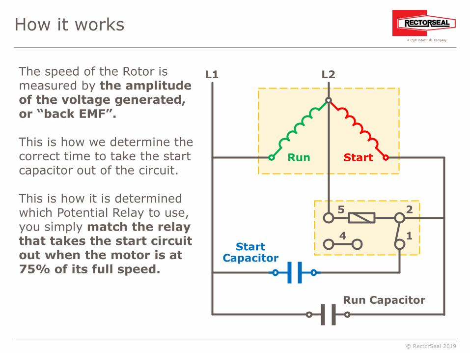
How it works
The speed of the Rotor is measured by the amplitude of the voltage generated, or “back EMF”.
This is how we determine the correct time to take the start capacitor out of the circuit.
This is how it is determined which Potential Relay to use, you simply match the relay that takes the start circuit out when the motor is at 75% of its full speed.
StartCapacitor
StartRun
L1 L2
Run Capacitor
5 2
14

© RectorSeal 2019
Copeland handbook has 64 Potential Relays!
COPELANDPART NO.
PICK UPVOLTS
DROP OUT VOLTS
CONTVOLT
040-000-1-55 190-200 60-121 375040-000-1-56 200-220 40-90 332040-000-1-58 260-280 60-140 395040-000-1-59 210-230 60-150 420040-000-1-60 190-200 55-115 332040-000-1-61 320-340 60-120 420040-000-1-62 150-160 35-77 253040-000-1-63 300-320 50-140 375040-000-1-64 260-280 60-150 420040-000-1-66 300-320 45-115 332040-000-1-68 240-260 60-121 420040-000-1-69 320-340 60-160 502040-000-1-71 280-300 50-110 375040-000-1-75 120-130 15-40 130040-000-1-77 240-260 35-77 253040-000-1-79 170-180 40-96 332040-000-1-80 140-150 20-65 168040-000-1-82 220-240 40-90 332040-000-1-83 260-280 60-140 395040-000-1-84 280-300 75-150 420040-000-1-85 280-300 75-170 495040-000-1-86 220-280 60-135 495040-000-1-87 260-280 60-140 395040-000-7-00 150-160 15-45 130040-000-7-04 340-360 55-125 336040-004-6-00 340-360 55-125 336040-004-6-01 320-340 60-140 395040-004-6-02 320-340 75-160 420040-004-6-05 300-320 45-115 256040-004-6-08 170-180 45-90 256040-004-6-09 150-160 20-55 130040-004-6-10 340-360 45-115 256040-004-6-16 280-300 55-125 336
COPELANDPART NO.
PICK UPVOLTS
DROP OUT VOLTS
CONTVOLT
040-000-1-00 320-340 60-140 395040-000-1-01 150-160 15-55 130040-000-1-03 340-360 45-155 156040-000-1-04 340-360 55-125 336040-000-1-05 280-300 50-125 336040-000-1-08 320-340 60-160 420040-000-1-09 300-320 45-115 256040-000-1-11 170-180 35-90 253040-000-1-12 260-280 60-150 420040-000-1-17 260-280 50-140 375040-000-1-18 300-320 50-140 375040-000-1-19 240-260 60-140 375040-000-1-20 190-200 40-130 375040-000-1-22 120-130 15-50 130040-000-1-24 240-260 35-95 253040-000-1-25 150-160 35-95 253040-000-1-34 240-260 60-150 420040-000-1-35 210-230 60-150 420040-000-1-36 200-220 40-115 332040-000-1-37 170-180 40-115 332040-000-1-38 190-200 55-115 332040-000-1-41 140-150 20-65 168040-000-1-42 260-280 60-140 395040-000-1-43 280-300 75-150 420040-000-1-45 280-300 75-150 495040-000-1-46 220-240 40-115 332040-000-1-47 220-280 60-135 495040-000-1-48 150-160 15-40 130040-000-1-49 340-360 50-100 332040-000-1-50 340-360 55-125 336040-000-1-51 170-180 35-77 253040-000-1-53 260-280 50-110 375040-000-1-54 240-260 60-121 375

© RectorSeal 2019
Capacitor and Potential Relay variations
With 100’s of variations of “back EMF”, there are 100’s of Potential Relay and Start Capacitor combinations.• Relays are calibrated to have different “Pick Up”, “Drop Out”, “Continuous”,
“Impulse”, and “Response Time” voltage.

© RectorSeal 2019
Copeland handbook has 64 Potential Relays!
COPELANDPART NO.
PICK UPVOLTS
DROP OUT VOLTS
CONTVOLT
040-000-1-55 190-200 60-121 375040-000-1-56 200-220 40-90 332040-000-1-58 260-280 60-140 395040-000-1-59 210-230 60-150 420040-000-1-60 190-200 55-115 332040-000-1-61 320-340 60-120 420040-000-1-62 150-160 35-77 253040-000-1-63 300-320 50-140 375040-000-1-64 260-280 60-150 420040-000-1-66 300-320 45-115 332040-000-1-68 240-260 60-121 420040-000-1-69 320-340 60-160 502040-000-1-71 280-300 50-110 375040-000-1-75 120-130 15-40 130040-000-1-77 240-260 35-77 253040-000-1-79 170-180 40-96 332040-000-1-80 140-150 20-65 168040-000-1-82 220-240 40-90 332040-000-1-83 260-280 60-140 395040-000-1-84 280-300 75-150 420040-000-1-85 280-300 75-170 495040-000-1-86 220-280 60-135 495040-000-1-87 260-280 60-140 395040-000-7-00 150-160 15-45 130040-000-7-04 340-360 55-125 336040-004-6-00 340-360 55-125 336040-004-6-01 320-340 60-140 395040-004-6-02 320-340 75-160 420040-004-6-05 300-320 45-115 256040-004-6-08 170-180 45-90 256040-004-6-09 150-160 20-55 130040-004-6-10 340-360 45-115 256040-004-6-16 280-300 55-125 336
COPELANDPART NO.
PICK UPVOLTS
DROP OUT VOLTS
CONTVOLT
040-000-1-00 320-340 60-140 395040-000-1-01 150-160 15-55 130040-000-1-03 340-360 45-155 156040-000-1-04 340-360 55-125 336040-000-1-05 280-300 50-125 336040-000-1-08 320-340 60-160 420040-000-1-09 300-320 45-115 256040-000-1-11 170-180 35-90 253040-000-1-12 260-280 60-150 420040-000-1-17 260-280 50-140 375040-000-1-18 300-320 50-140 375040-000-1-19 240-260 60-140 375040-000-1-20 190-200 40-130 375040-000-1-22 120-130 15-50 130040-000-1-24 240-260 35-95 253040-000-1-25 150-160 35-95 253040-000-1-34 240-260 60-150 420040-000-1-35 210-230 60-150 420040-000-1-36 200-220 40-115 332040-000-1-37 170-180 40-115 332040-000-1-38 190-200 55-115 332040-000-1-41 140-150 20-65 168040-000-1-42 260-280 60-140 395040-000-1-43 280-300 75-150 420040-000-1-45 280-300 75-150 495040-000-1-46 220-240 40-115 332040-000-1-47 220-280 60-135 495040-000-1-48 150-160 15-40 130040-000-1-49 340-360 50-100 332040-000-1-50 340-360 55-125 336040-000-1-51 170-180 35-77 253040-000-1-53 260-280 50-110 375040-000-1-54 240-260 60-121 375

© RectorSeal 2019
Voltage variance specification
Voltage is specified between the Start and Run terminals when a motor is designed, in order to match the Run Capacitor requirements.
Voltage between Start and Common varies by 100’s of volts• whereas voltage between the Start and Run terminals is “consistent”, varyies by only 10’s of volts. • Why, because Start and Run terminal voltage variation is “specified”
by the Engineers in the design process.
www.rectorseal.com

© RectorSeal 2019
Agenda Overview
Review of conventional 3-wire hard startdevices and components
Review of 2-wire hard start technology
3-wire and 2-wire devices inreal-world testing
Competitor technologies
True Run Capacitor test

© RectorSeal 2019
How the 2 Wire System Was Found
We now know that voltage between Start and Common terminals varies and voltage between Start and Run terminals is relatively constant, so what does that mean?
All PSC (Permanent Split Capacitor) motors have essentially the same back EMF between Start and Run terminals.
www.rectorseal.com

© RectorSeal 2019
The First Move
On this diagram we will be taking the wire from theCommon terminal and move it over to the Run terminal.
Start winding Run Winding
Potential
Relay
Run Capacitor
Start Capacitor
RS CCommon RunStart

© RectorSeal 2019
RS C
Updated 3-wire hard start schematic
Start winding Run Winding
Potential
Relay
Run Capacitor
Start Capacitor
Common RunStart
© RectorSeal 2019
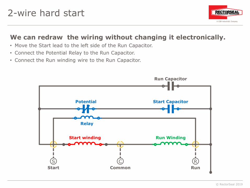
2-wire hard start
RS C
Start winding Run Winding
Potential
Relay
Run Capacitor
Start Capacitor
Common RunStart
We can redraw the wiring without changing it electronically.• Move the Start lead to the left side of the Run Capacitor.• Connect the Potential Relay to the Run Capacitor.• Connect the Run winding wire to the Run Capacitor.

© RectorSeal 2019
2-wire diagram
RS C
Start winding Run Winding
Potential
Relay
Run Capacitor
Start Capacitor
Common RunStart
The diagram is unchanged electronically, but we have moved the wiring into a new schematic.• The Potential Relay and Start Capacitor are inside one box with 2 wires coming out.• Reversing the 2-wire configuration across the Run Capacitor will not change the function
in any way.

© RectorSeal 2019
The Kickstart® Way to Read Counter EMF
• Read the Counter EMF between Start and Run terminals,• use only ONE relay instead of having to pick from 100’s of relays.
• Hard start kit with a single Potential Relay that can be used on all 2-pole PSC motors with two wires that are not dedicated!
R
Start winding Run Winding
Potential
Relay
Run Capacitor
Start Capacitor
Common RunStart
Counter EMF
±10’s VoltsS C
© RectorSeal 2019
Locked Rotor Amps
Locked Rotor Amps (LRA), or Locked Rotor Current, is the amount of energy needed to begin the motion of the rotor within an electric motor.
LRA is much greater that the Full Load Amps (FLA) or Running Load Amps (RLA) because of the power required to operate the equipment attached to the electric motor during start-up as well.
- LRA can be as much as 600 to 800% the normal FLA (depending on the motor)
www.rectorseal.com

© RectorSeal 2019
Compressor with no hard start
-200
-100
0
100
200
300
400
500
0 100 200 300 400 500 600
Time (ms)
Volts (Amps)
3 ton recip. compressor230v @ LRA NO HARD START pressure equalized @ 140 psig
Run Capacitor Voltage – RMSRun Winding Amps

© RectorSeal 2019
As the motor begins to turn, the rotor struggles to get to operating speed
-5
-4
-3
-2
-1
0
1
2
3
4
5
6
0 50 100 150 200 250
RotorRun Winding CurrentRun Capacitor Voltage
Note: IL and Vc NOT TO SCALE Time (ms)
Number of turns
3 ton recip. compressor rotor motionNO Hard Start
Rotation(no. of turns)
Counter EMF
LRA

© RectorSeal 2019
As the motor begins to turn, the rotor struggles to get to operating speed
-5
-4
-3
-2
-1
0
1
2
3
4
5
6
0 50 100 150 200 250
RotorRun Winding CurrentRun Capacitor Voltage
Note: IL and Vc NOT TO SCALE Time (ms)
Number of turns
3 ton recip. compressor rotor motionNO Hard Start
75% of full speed after
2.5 - 3 turns of compressor
motor

© RectorSeal 2019
Agenda Overview
Review of conventional 3-wire hard startdevices and components
Review of 2-wire hard start technology
3-wire and 2-wire devices inreal-world testing
Competitor technologies
True Run Capacitor test

© RectorSeal 2019
Compressor with factory hard start
Time (ms)
Amps
3 ton recip. compressor187v FACTORY HARD START (145 MFD) 90 # S - 280 # D
-150
-100
-50
0
50
100
150
0 100 200 300 400 500 600 700 800
Run Winding CurrentStart winding Current

© RectorSeal 2019
-150
-100
-50
0
50
100
150
0 100 200 300 400 500 600 700 800
Compressor with KickStart TO-5
Time (ms)
Amps
3 ton recip. compressor187v KICKSTART TO-5 (189 MFD) 90 # S - 280 # D
Run Winding CurrentStart winding Current

© RectorSeal 2019
Factory hard start vs KickStart TO-5
WITH KICKSTART TO-5 (189 MFD)
Time (ms)
Amps
-150
-100
-50
0
50
100
150
0 100 200 300 400 500 600 700 800
Time (ms)
Amps
-150
-100
-50
0
50
100
150
0 100 200 300 400 500 600 700 800
Run Winding CurrentStart winding Current
3 ton recip. Compressor 187v FACTORY HARD START (145 MFD) 90 # S - 280 # D

© RectorSeal 2019
Copeland Scroll hard start comparison
WITH KICKSTART KS-1
Copeland Scroll ZR57K3-PFV 197 V NO HARD START DEVICE
Time (ms)
Amps
Time (ms)
Amps
Run Winding CurrentStart winding Current
-300
-200
-100
0
100
200
300
0 100 200 300 400 500 600
-300
-200
-100
0
100
200
300
0 100 200 300 400 500 600
© RectorSeal 2019
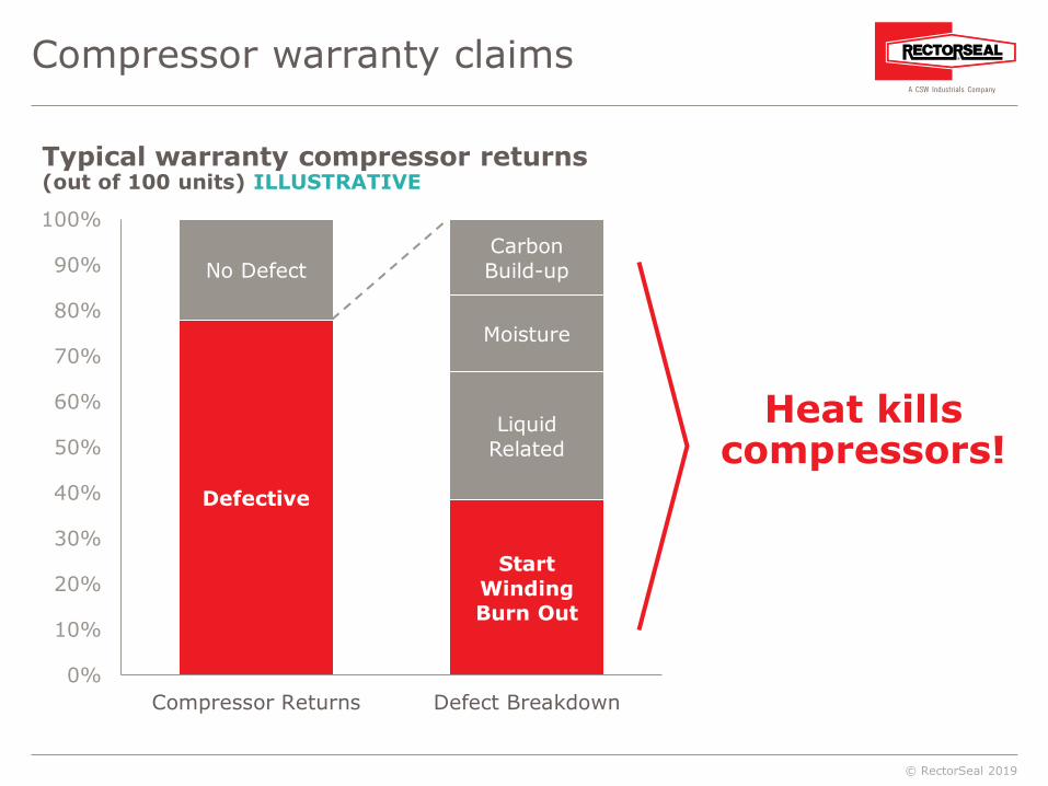
Compressor warranty claims
Defective
No Defect
Start WindingBurn Out
LiquidRelated
Moisture
CarbonBuild-up
0%
10%
20%
30%
40%
50%
60%
70%
80%
90%
100%
Compressor Returns Defect Breakdown
Heat killscompressors!
Typical warranty compressor returns(out of 100 units) ILLUSTRATIVE

© RectorSeal 2019
Agenda Overview
Review of conventional 3-wire hard startdevices and components
Review of 2-wire hard start technology
3-wire and 2-wire devices inreal-world testing
Competitor technologies
True Run Capacitor test

© RectorSeal 2019
PTCRPositive Temperature Coefficient Resistor
20° 248° Temp t°
Time T0.8 sec
Cur
rent
resi
stan
t
(I) R
Current
Resistant
CP (Curie Point):Temp where material can no longer conduct
electricity
PTCR discs
PTCR discs are appealing because they are a cheap technology compared to OEM-approved Potential Relays

© RectorSeal 2019
Timing Device
Set duration could cause start to happen too early or too late.

© RectorSeal 2019
Technology comparison
Run Winding Current Start winding Current
Copeland CRA1 0150-PFV 197 V PTCR WITH CAPACITOR
Time (ms)
Amps
Copeland CRA1 0150-PFV 197 V ELECTRONIC TIMING DEVICE W/ 88-106 START CAPACITOR
Time (ms)
Amps
Copeland CRA1 0150-PFV 197 V KICKSTART TO-5 OR MATCHED FACTORY 3-WIRE KIT
Time (ms)
Amps
-80
-40
0
40
80
0 100 200 300 400 500 600 700 800
-80
-40
0
40
80
0 100 200 300 400 500 600 700 800
-80
-40
0
40
80
0 100 200 300 400 500 600 700 800

© RectorSeal 2019
The so-called “universal” 3-wire kits
It IS impossible tomake a universalhard start kit usingthe standard 3-wire connections.
But some stillsell them.

© RectorSeal 2019
Copeland handbook has 64 Potential Relays
COPELANDPART NO.
PICK UPVOLTS
DROP OUT VOLTS
CONTVOLT
040-000-1-55 190-200 60-121 375040-000-1-56 200-220 40-90 332040-000-1-58 260-280 60-140 395040-000-1-59 210-230 60-150 420040-000-1-60 190-200 55-115 332040-000-1-61 320-340 60-120 420040-000-1-62 150-160 35-77 253040-000-1-63 300-320 50-140 375040-000-1-64 260-280 60-150 420040-000-1-66 300-320 45-115 332040-000-1-68 240-260 60-121 420040-000-1-69 320-340 60-160 502040-000-1-71 280-300 50-110 375040-000-1-75 120-130 15-40 130040-000-1-77 240-260 35-77 253040-000-1-79 170-180 40-96 332040-000-1-80 140-150 20-65 168040-000-1-82 220-240 40-90 332040-000-1-83 260-280 60-140 395040-000-1-84 280-300 75-150 420040-000-1-85 280-300 75-170 495040-000-1-86 220-280 60-135 495040-000-1-87 260-280 60-140 395040-000-7-00 150-160 15-45 130040-000-7-04 340-360 55-125 336040-004-6-00 340-360 55-125 336040-004-6-01 320-340 60-140 395040-004-6-02 320-340 75-160 420040-004-6-05 300-320 45-115 256040-004-6-08 170-180 45-90 256040-004-6-09 150-160 20-55 130040-004-6-10 340-360 45-115 256040-004-6-16 280-300 55-125 336
COPELANDPART NO.
PICK UPVOLTS
DROP OUT VOLTS
CONTVOLT
040-000-1-00 320-340 60-140 395040-000-1-01 150-160 15-55 130040-000-1-03 340-360 45-155 156040-000-1-04 340-360 55-125 336040-000-1-05 280-300 50-125 336040-000-1-08 320-340 60-160 420040-000-1-09 300-320 45-115 256040-000-1-11 170-180 35-90 253040-000-1-12 260-280 60-150 420040-000-1-17 260-280 50-140 375040-000-1-18 300-320 50-140 375040-000-1-19 240-260 60-140 375040-000-1-20 190-200 40-130 375040-000-1-22 120-130 15-50 130040-000-1-24 240-260 35-95 253040-000-1-25 150-160 35-95 253040-000-1-34 240-260 60-150 420040-000-1-35 210-230 60-150 420040-000-1-36 200-220 40-115 332040-000-1-37 170-180 40-115 332040-000-1-38 190-200 55-115 332040-000-1-41 140-150 20-65 168040-000-1-42 260-280 60-140 395040-000-1-43 280-300 75-150 420040-000-1-45 280-300 75-150 495040-000-1-46 220-240 40-115 332040-000-1-47 220-280 60-135 495040-000-1-48 150-160 15-40 130040-000-1-49 340-360 50-100 332040-000-1-50 340-360 55-125 336040-000-1-51 170-180 35-77 253040-000-1-53 260-280 50-110 375040-000-1-54 240-260 60-121 375
One Potential Relay cannot replace all 64 relays in a 3-wire configuration!
© RectorSeal 2019
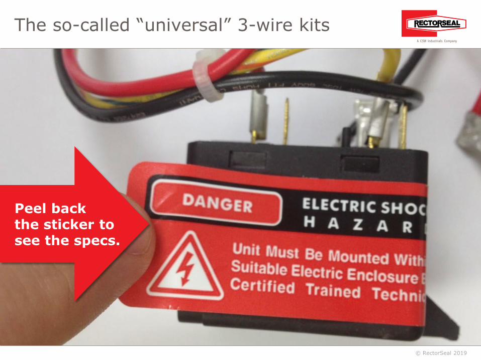
The so-called “universal” 3-wire kits
Peel backthe sticker tosee the specs.
© RectorSeal 2019
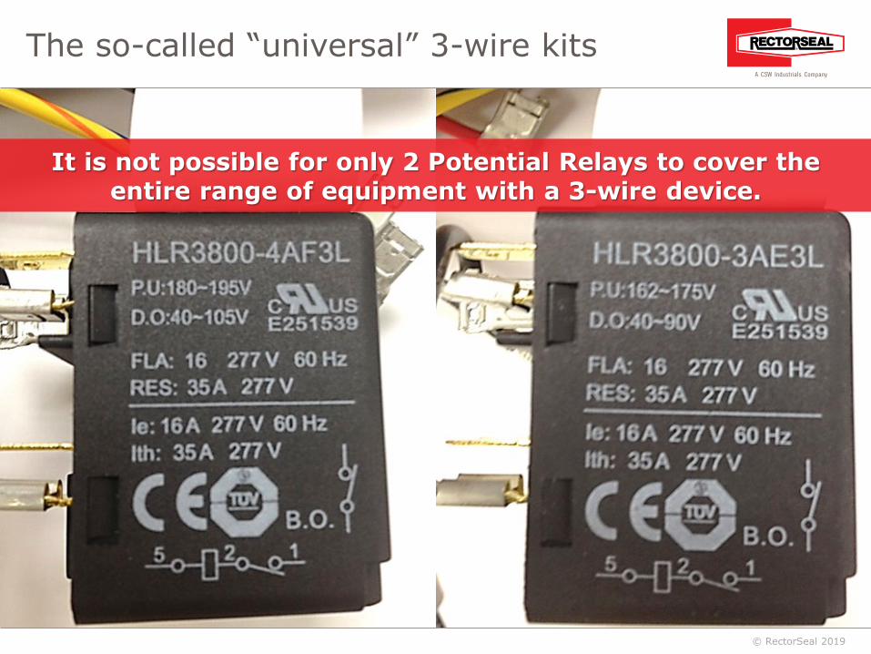
It is not possible for only 2 Potential Relays to cover theentire range of equipment with a 3-wire device.
The so-called “universal” 3-wire kits

© RectorSeal 2019
The so-called “universal” 3-wire kit’s compatibility with Copeland
COPELANDPART NO.
PICK UPVOLTS
DROP OUT VOLTS
CONTVOLT
040-000-1-55 190-200 60-121 375040-000-1-56 200-220 40-90 332040-000-1-58 260-280 60-140 395040-000-1-59 210-230 60-150 420040-000-1-60 190-200 55-115 332040-000-1-61 320-340 60-120 420040-000-1-62 150-160 35-77 253040-000-1-63 300-320 50-140 375040-000-1-64 260-280 60-150 420040-000-1-66 300-320 45-115 332040-000-1-68 240-260 60-121 420040-000-1-69 320-340 60-160 502040-000-1-71 280-300 50-110 375040-000-1-75 120-130 15-40 130040-000-1-77 240-260 35-77 253040-000-1-79 170-180 40-96 332040-000-1-80 140-150 20-65 168040-000-1-82 220-240 40-90 332040-000-1-83 260-280 60-140 395040-000-1-84 280-300 75-150 420040-000-1-85 280-300 75-170 495040-000-1-86 220-280 60-135 495040-000-1-87 260-280 60-140 395040-000-7-00 150-160 15-45 130040-000-7-04 340-360 55-125 336040-004-6-00 340-360 55-125 336040-004-6-01 320-340 60-140 395040-004-6-02 320-340 75-160 420040-004-6-05 300-320 45-115 256040-004-6-08 170-180 45-90 256040-004-6-09 150-160 20-55 130040-004-6-10 340-360 45-115 256040-004-6-16 280-300 55-125 336
COPELANDPART NO.
PICK UPVOLTS
DROP OUT VOLTS
CONTVOLT
040-000-1-00 320-340 60-140 395040-000-1-01 150-160 15-55 130040-000-1-03 340-360 45-155 156040-000-1-04 340-360 55-125 336040-000-1-05 280-300 50-125 336040-000-1-08 320-340 60-160 420040-000-1-09 300-320 45-115 256040-000-1-11 170-180 35-90 253040-000-1-12 260-280 60-150 420040-000-1-17 260-280 50-140 375040-000-1-18 300-320 50-140 375040-000-1-19 240-260 60-140 375040-000-1-20 190-200 40-130 375040-000-1-22 120-130 15-50 130040-000-1-24 240-260 35-95 253040-000-1-25 150-160 35-95 253040-000-1-34 240-260 60-150 420040-000-1-35 210-230 60-150 420040-000-1-36 200-220 40-115 332040-000-1-37 170-180 40-115 332040-000-1-38 190-200 55-115 332040-000-1-41 140-150 20-65 168040-000-1-42 260-280 60-140 395040-000-1-43 280-300 75-150 420040-000-1-45 280-300 75-150 495040-000-1-46 220-240 40-115 332040-000-1-47 220-280 60-135 495040-000-1-48 150-160 15-40 130040-000-1-49 340-360 50-100 332040-000-1-50 340-360 55-125 336040-000-1-51 170-180 35-77 253040-000-1-53 260-280 50-110 375040-000-1-54 240-260 60-121 375
Works for less than 10% of relays on all Copeland compressors!

© RectorSeal 2019
COPELANDPART NO.
PICK UPVOLTS
DROP OUT VOLTS
CONTVOLT
040-000-1-55 190-200 60-121 375040-000-1-56 200-220 40-90 332040-000-1-58 260-280 60-140 395040-000-1-59 210-230 60-150 420040-000-1-60 190-200 55-115 332040-000-1-61 320-340 60-120 420040-000-1-62 150-160 35-77 253040-000-1-63 300-320 50-140 375040-000-1-64 260-280 60-150 420040-000-1-66 300-320 45-115 332040-000-1-68 240-260 60-121 420040-000-1-69 320-340 60-160 502040-000-1-71 280-300 50-110 375040-000-1-75 120-130 15-40 130040-000-1-77 240-260 35-77 253040-000-1-79 170-180 40-96 332040-000-1-80 140-150 20-65 168040-000-1-82 220-240 40-90 332040-000-1-83 260-280 60-140 395040-000-1-84 280-300 75-150 420040-000-1-85 280-300 75-170 495040-000-1-86 220-280 60-135 495040-000-1-87 260-280 60-140 395040-000-7-00 150-160 15-45 130040-000-7-04 340-360 55-125 336040-004-6-00 340-360 55-125 336040-004-6-01 320-340 60-140 395040-004-6-02 320-340 75-160 420040-004-6-05 300-320 45-115 256040-004-6-08 170-180 45-90 256040-004-6-09 150-160 20-55 130040-004-6-10 340-360 45-115 256040-004-6-16 280-300 55-125 336
COPELANDPART NO.
PICK UPVOLTS
DROP OUT VOLTS
CONTVOLT
040-000-1-00 320-340 60-140 395040-000-1-01 150-160 15-55 130040-000-1-03 340-360 45-155 156040-000-1-04 340-360 55-125 336040-000-1-05 280-300 50-125 336040-000-1-08 320-340 60-160 420040-000-1-09 300-320 45-115 256040-000-1-11 170-180 35-90 253040-000-1-12 260-280 60-150 420040-000-1-17 260-280 50-140 375040-000-1-18 300-320 50-140 375040-000-1-19 240-260 60-140 375040-000-1-20 190-200 40-130 375040-000-1-22 120-130 15-50 130040-000-1-24 240-260 35-95 253040-000-1-25 150-160 35-95 253040-000-1-34 240-260 60-150 420040-000-1-35 210-230 60-150 420040-000-1-36 200-220 40-115 332040-000-1-37 170-180 40-115 332040-000-1-38 190-200 55-115 332040-000-1-41 140-150 20-65 168040-000-1-42 260-280 60-140 395040-000-1-43 280-300 75-150 420040-000-1-45 280-300 75-150 495040-000-1-46 220-240 40-115 332040-000-1-47 220-280 60-135 495040-000-1-48 150-160 15-40 130040-000-1-49 340-360 50-100 332040-000-1-50 340-360 55-125 336040-000-1-51 170-180 35-77 253040-000-1-53 260-280 50-110 375040-000-1-54 240-260 60-121 375
Kickstart’s compatibility with Copeland
Tested to perform with each PSC single-phase compressor.

© RectorSeal 2019
-300
-250
-200
-150
-100
-50
0
50
100
150
200
250
300
350
0 100 200 300 400 500 600
Copeland scroll using wrong relay
Time (ms)
Amps
Copeland scroll ZR42K3 – PFVWRONG RELAY
Run Winding AmpsStart winding Amps
Potential Relay picks up too soon
© RectorSeal 2019
-200
-150
-100
-50
0
50
100
150
200
0 100 200 300 400 500 600 700
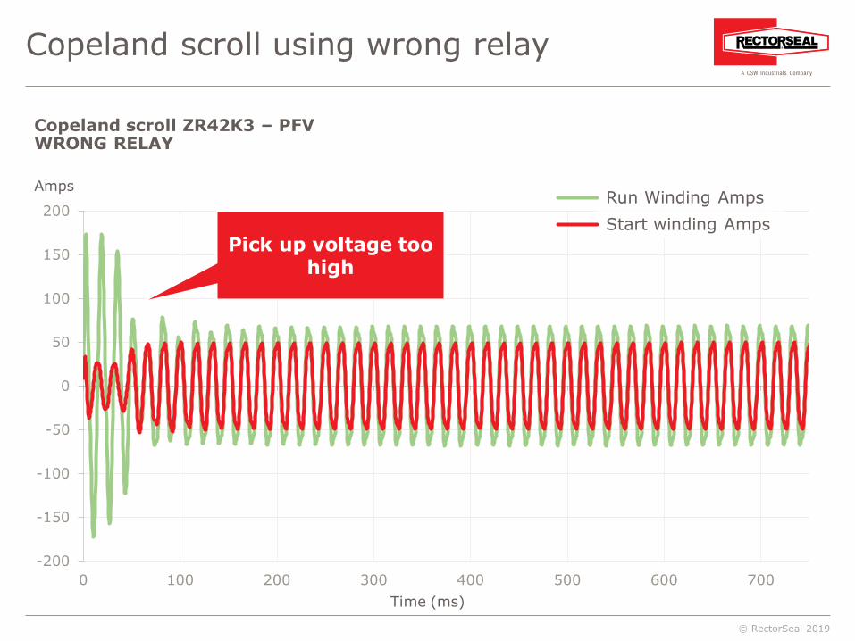
Copeland scroll using wrong relay
Time (ms)
Amps
Copeland scroll ZR42K3 – PFVWRONG RELAY
Run Winding AmpsStart winding Amps
Pick up voltage too high

© RectorSeal 2019
-300
-200
-100
0
100
200
300
0 100 200 300 400 500 600
Correct Potential Relay pick-up
Run Winding CurrentStart winding Current
Copeland scroll ZR57K3-PFV197 V KICKSTART KS1 - GE-3ARR3CT3P5/kit
Time (ms)
Amps
© RectorSeal 2019
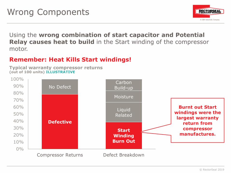
Wrong Components
Defective
No Defect
Start WindingBurn Out
LiquidRelated
Moisture
CarbonBuild-up
0%10%20%30%40%50%60%70%80%90%
100%
Compressor Returns Defect Breakdown
Using the wrong combination of start capacitor and Potential Relay causes heat to build in the Start winding of the compressor motor.
Remember: Heat Kills Start windings!
Burnt out Start windings were the largest warranty
return from compressor
manufactures.
Typical warranty compressor returns(out of 100 units) ILLUSTRATIVE

© RectorSeal 2019
Tested quality and reliability with OEM approval.

© RectorSeal 2019
Agenda Overview
Review of conventional 3-wire hard startdevices and components
Review of 2-wire hard start technology
3-wire and 2-wire devices inreal-world testing
Competitor technologies
True Run Capacitor test

© RectorSeal 2019
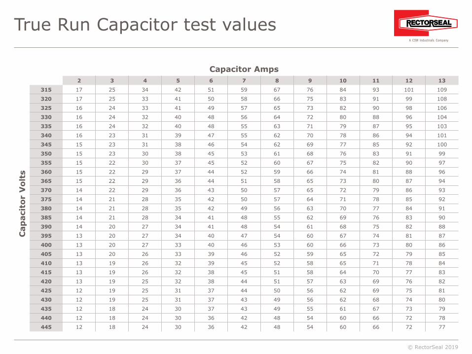
True Run Capacitor test
Run Cap Test: Process of testing the Run Capacitorwhile the system is running, providing an accurate reading.• Start compressor with Run Capacitor connected.• Measure and record the Amp Draw of the capacitor (multiply 2654).• Measure and record the Applied Voltage.
AMP DRAW X 2654
APPLIED VOLTAGEMFD = = 50.2
Example:Capacitor draws 7 amps at 370 volts
Calculated value should be within 10% of value
stamped capacitor.
7X 2654
370MFD = = 50.2
© RectorSeal 2019
True Run Capacitor test values
Capacitor Amps
Cap
acit
or V
olts
2 3 4 5 6 7 8 9 10 11 12 13
315 17 25 34 42 51 59 67 76 84 93 101 109
320 17 25 33 41 50 58 66 75 83 91 99 108
325 16 24 33 41 49 57 65 73 82 90 98 106
330 16 24 32 40 48 56 64 72 80 88 96 104
335 16 24 32 40 48 55 63 71 79 87 95 103
340 16 23 31 39 47 55 62 70 78 86 94 101
345 15 23 31 38 46 54 62 69 77 85 92 100
350 15 23 30 38 45 53 61 68 76 83 91 99
355 15 22 30 37 45 52 60 67 75 82 90 97
360 15 22 29 37 44 52 59 66 74 81 88 96
365 15 22 29 36 44 51 58 65 73 80 87 94
370 14 22 29 36 43 50 57 65 72 79 86 93
375 14 21 28 35 42 50 57 64 71 78 85 92
380 14 21 28 35 42 49 56 63 70 77 84 91
385 14 21 28 34 41 48 55 62 69 76 83 90
390 14 20 27 34 41 48 54 61 68 75 82 88
395 13 20 27 34 40 47 54 60 67 74 81 87
400 13 20 27 33 40 46 53 60 66 73 80 86
405 13 20 26 33 39 46 52 59 65 72 79 85
410 13 19 26 32 39 45 52 58 65 71 78 84
415 13 19 26 32 38 45 51 58 64 70 77 83
420 13 19 25 32 38 44 51 57 63 69 76 82
425 12 19 25 31 37 44 50 56 62 69 75 81
430 12 19 25 31 37 43 49 56 62 68 74 80
435 12 18 24 30 37 43 49 55 61 67 73 79
440 12 18 24 30 36 42 48 54 60 66 72 78
445 12 18 24 30 36 42 48 54 60 66 72 77

© RectorSeal 2019
Kickstart® models
TO-5• Maximum Torque.• For all reciprocating, scroll and
rotary compressors 1 to 3 tons.
KS-1• Maximum Torque.• For all reciprocating, scroll and
rotary compressors 3.5 to 5 tons.

© RectorSeal 2019
Summary
• Heat Kills Start windings!• KickStart does not generate heat build up.• PTCR and Timer devices do not work consistently.• A "universal" 3-wire only meets a subset of applications.
• Correct Potential Relay and Start Capacitors reduces damageto compressors.
• Always test your Run Capacitor.
www.rectorseal.com

© RectorSeal 2019
Related Documents