Compression membrane action in composite slabs Autor(en): Peel Cross, R.J. / Rankin, G.I.B. / Gilbert, S.G. Objekttyp: Article Zeitschrift: IABSE reports = Rapports AIPC = IVBH Berichte Band (Jahr): 999 (1997) Persistenter Link: http://doi.org/10.5169/seals-999 PDF erstellt am: 13.09.2022 Nutzungsbedingungen Die ETH-Bibliothek ist Anbieterin der digitalisierten Zeitschriften. Sie besitzt keine Urheberrechte an den Inhalten der Zeitschriften. Die Rechte liegen in der Regel bei den Herausgebern. Die auf der Plattform e-periodica veröffentlichten Dokumente stehen für nicht-kommerzielle Zwecke in Lehre und Forschung sowie für die private Nutzung frei zur Verfügung. Einzelne Dateien oder Ausdrucke aus diesem Angebot können zusammen mit diesen Nutzungsbedingungen und den korrekten Herkunftsbezeichnungen weitergegeben werden. Das Veröffentlichen von Bildern in Print- und Online-Publikationen ist nur mit vorheriger Genehmigung der Rechteinhaber erlaubt. Die systematische Speicherung von Teilen des elektronischen Angebots auf anderen Servern bedarf ebenfalls des schriftlichen Einverständnisses der Rechteinhaber. Haftungsausschluss Alle Angaben erfolgen ohne Gewähr für Vollständigkeit oder Richtigkeit. Es wird keine Haftung übernommen für Schäden durch die Verwendung von Informationen aus diesem Online-Angebot oder durch das Fehlen von Informationen. Dies gilt auch für Inhalte Dritter, die über dieses Angebot zugänglich sind. Ein Dienst der ETH-Bibliothek ETH Zürich, Rämistrasse 101, 8092 Zürich, Schweiz, www.library.ethz.ch http://www.e-periodica.ch

Welcome message from author
This document is posted to help you gain knowledge. Please leave a comment to let me know what you think about it! Share it to your friends and learn new things together.
Transcript

Compression membrane action in compositeslabs
Autor(en): Peel Cross, R.J. / Rankin, G.I.B. / Gilbert, S.G.
Objekttyp: Article
Zeitschrift: IABSE reports = Rapports AIPC = IVBH Berichte
Band (Jahr): 999 (1997)
Persistenter Link: http://doi.org/10.5169/seals-999
PDF erstellt am: 13.09.2022
NutzungsbedingungenDie ETH-Bibliothek ist Anbieterin der digitalisierten Zeitschriften. Sie besitzt keine Urheberrechte anden Inhalten der Zeitschriften. Die Rechte liegen in der Regel bei den Herausgebern.Die auf der Plattform e-periodica veröffentlichten Dokumente stehen für nicht-kommerzielle Zwecke inLehre und Forschung sowie für die private Nutzung frei zur Verfügung. Einzelne Dateien oderAusdrucke aus diesem Angebot können zusammen mit diesen Nutzungsbedingungen und denkorrekten Herkunftsbezeichnungen weitergegeben werden.Das Veröffentlichen von Bildern in Print- und Online-Publikationen ist nur mit vorheriger Genehmigungder Rechteinhaber erlaubt. Die systematische Speicherung von Teilen des elektronischen Angebotsauf anderen Servern bedarf ebenfalls des schriftlichen Einverständnisses der Rechteinhaber.
HaftungsausschlussAlle Angaben erfolgen ohne Gewähr für Vollständigkeit oder Richtigkeit. Es wird keine Haftungübernommen für Schäden durch die Verwendung von Informationen aus diesem Online-Angebot oderdurch das Fehlen von Informationen. Dies gilt auch für Inhalte Dritter, die über dieses Angebotzugänglich sind.
Ein Dienst der ETH-BibliothekETH Zürich, Rämistrasse 101, 8092 Zürich, Schweiz, www.library.ethz.ch
http://www.e-periodica.ch

385
Compression Membrane Action in Composite Slabs
R.J. PEEL CROSS
Ernest Griffiths and SonLiverpool, UK
G.I.B. RANKINDrQueen's UniversityBelfast, UK
S.G. GILBERTDrQueen's UniversityBelfast, UK
A.E. LONGProfessorQueen's UniversityBelfast, UK
Summary x
This paper discusses the results from a two year research project which studied the effects ofCompressive Membrane Action (CMA) on composite metal decking/concrete slabs before and
after fire. The paper concentrates on work carried out on frill scale slabs in the BRE test buildingat Cardington, but compares these results with those obtained from slab strips tested in the
laboratory. It was found that fire damaged slabs exhibited far greater strengths than previouslysupposed, some held loads higher than those predicted by yield line analysis.
1. Introduction
Compressive Membrane Action is the two way arching effect which occurs when a laterallyrestrained slab is loaded (1). The load is resisted by a compressive force which extends throughthe slab from the load to the supports (see Fig 1). The greater the element depth/length ratio is,the greater is the amount of arching which occurs. CMA is already used to justify a reduction inthe amount of reinforcing steel used in certain beam and slab bridge decks (2), but has not yetbeen applied in practice to other structures (3). The purpose of this research was to find outwhether CMA contributes to the strength of composite metal decking/concrete slabs in buildings,and whether it helps to sustain load in a composite slab which has been badly damaged by fire (4).
Thus, a series of full scale in-situ and laboratory tests was devised to investigate the effects of the
following parameters:
a) slab boundary conditions - interior, edge and corner composite slabs were tested and
b) fire damage - composite slabs were tested before and after fire loading.
2. Tests at BRE Cardington
The full scale in-situ tests were carried out in the Building Research Establishment's 'LargeBuilding Test Facility' (LBTF) at Cardington, UK. The building is eight storeys high and
replicates a typical steel framed, composite slab office block with a design dead load of

386 COMPRESSION MEMBRANE ACTION IN COMPOSITE SLABS
3.65kN/m2 and design imposed load of 3.5kN/m2. It has been built purely for research purposes,in particular to assess the effect of fire on a 'real' building.
The tests were carried out in two phases, the first on undamaged slabs (pre-fire tests) and thesecond on fire damaged slabs (post-fire tests) at the locations indicated in Fig 2. Each set of slabs
underwent two tests, the first being a proof load test and the second an ultimate load test. Loadswere applied along the quarterpoints of the slab in order to simulate the bending moments due toa uniformly distributed load. The load was applied hydraulically using ten 30 tonne jacks (Fig 3),except for the service load on the fire damaged slabs which was applied incrementally with 1.1
tonne sandbags. This was mainly because the panels were so distorted by the fire that it wouldhave been difficult to line up holes for the Macalloy bars over two floors. In addition, it wasknown that the slabs had sustained a superimposed load ofabout 2.4kN/m2 during the fire testand it was decided not to load the slab more than this in case the beam connections failed.
Load
Fig.l Arching action
9m
1
Edge Comer
A
1 Inter'l
-
Inter'l3m Comer Edge
Post-fire tests
on 3rd floorPre-fire tests
on 6 th floor
load spreading
• beams v
Îkent-
IMacalloy bars/ \
5 floorMiu±r -8^ '
kentledge
/ Tvb
[^"8 hydraulic jacks aSn
Fig.2 Cardington testpanels Fig. 3 Hydraulicfloor loading system
2.1 Proof load tests
2.1.1 Pre-fire proof load testsThe slabs were first loaded in 1.2kN/m2 increments up to an applied test load of 5.6kN/m2 (1.25Dead load + 1.25 Imposed load - slab self-weight - weight of test apparatus). Deflections weremeasured at each increment of load with a staff and level. This test was carried out twice and
then the load was allowed to remain on the slab for 24 hours. The deflections were taken beforeand after to ascertain whether any significant creep had occurred. The slabs deflected less than

R.J. PEEL CROSS, G.I.B. RANKIN, S.G. GILBERT, A.E. LONG 387
1/400 of the 3m span under the imposed load, and the 24 hour tests showed that no creepoccurred.
2.1.2 Post-fireproofload testsBefore these tests began, the slabs were subjected to a fire load ofup to 763°C. This procedure is
described in more detail in the BRE's newsletter, LBTF News, Issue 13, Summer 1996. For thistest it was decided to only load the slabs once as the floor was fairly badly damaged, and movingthe sandbags on and off the floor was causing the cracks along the edge of the slab to open upfurther. The load was taken up to a superimposed UDL of 2.4kN/m2. Although this load wasless than half the load for the pre-fire tests, the deflections were fairly similar, indicating that theslab was not maintaining load as well as before the fire. However this was to be expected, as thesteel frame had badly deformed, making the whole structure much less rigid.
Slab location Pre-fire tests: Post-fire tests:Deflection under 5.6kN/m2 Deflection under 2.4kN/m2
imposed load (mm) imposed load (mm)Internal 7 6
Edge 4.5 4
Corner Test not carried out 5
Table 1 Comparison ofslab central deflections before and afterfire
2.2 Ultimate load tests
The test rig set up was slightly different from the proof load tests (Fig 3), because only the slab
was to be loaded to Mure. As it was imperative that the steel frame did not fail, the test rig wasmoved up one floor so that it was immediately under the slab being tested. This created a self-
straining system whereby the load on the slab was resisted by the reactions of the loading rigagainst the steel beams.
2.2.1 Prefire ultimate load testsThe slabs were loaded in 1.2kN/m2 intervals, until they approached failure when the loadingincrements were reduced to 0.6kN/m2. At a load of about 15kN/m2, the decking began to debond
noisily from the concrete. It is likely that this was the point at which the concrete began to crackas well, but this was impossible to see with the decking in place. At this point, the stiffness of theslab reduced by about 60%. At about 2/3 of the ultimate load level, yielding of the decking beganto occur and the rate of deflection progressively increased until failure.
75
Applied 50
Load(kN/m2)
25
°0 20 40 60
Deflection (mm)
Fig.4 Pre-Fire Load/Deflection Resultsfor Internal Panel
failure
^ yielding
/V^debondingS deckine
of

388 COMPRESSION MEMBRANE ACTION IN COMPOSITE SLABS
In ail cases, failure consisted of a sudden, shear failure along one of the edges parallel to thespanning direction of the slab. The failure loads are shown in Table 2. It can be seen that thestrengths of the panels (except the post-fire internal panel) were considerably greater than the
predicted yield line loads, particularly for the pre-fire internal panel.
In general, the Mure load was related to the depth of the slab, which varied across the floor.However, the internal panel sustained a significantly higher load than the edge and corner slabs,
even though it was the least deep. This implies that the internal slab was restrained to a greaterextent by the surrounding slabs and beams indicating that there was a greater contribution ofCMA to the load carrying capacity of the internal slab.
2.2.2 Post-fire ultimate load testsThe fire load caused the slabs to crack along the beam lines. The slabs had deflected with thesteel beams which had deformed greatly due to the fire load. In these tests the decking was notheard to debond - presumably because this had already occurred under the fire load. As Murewas approached, the load was carefully controlled so that the slabs did not M catastrophically.
A summary of the failure loads is given in Table 2. The edge and corner slabs were not as badlydamaged as the internal panel in the fire and their Mure loads were correspondingly higher. Theinternal panel had deflected by nearly half a metre in places and so was much less rigid than in the
pre-fire tests. It is interesting to note that, even after the fire, all the panels withstood at leastthree times the required design ultimate load of 10.7kN/mz.
Slab location Cardington failureload-PcAR (kN/m2)
Yield line load -Pyl (kN/m1)
Pcar/Pyl
Pre-fireInternal 69.9 37.4 1.87
Edge 61.4 39.2 1.57
Corner 62.4 41.9 1.49
Post-fireInternal 38.0 (54%)* 38.9 0.98
Edge 46.4 (75%)* 38.5 1.20
Corner 47.4 (76%)* 37.0 1.28
*% ofpre-fire failure load
Table 2 Cardington Test Results and Theoretical Failure Loads
3. Laboratory Tests at Queen's University, Belfast
Four tests were carried out to assess the effect of fire on a slab. Two of the slabs were simplysupported and two were laterally restrained using a rig that had been built for the purpose. Thespecimens were designed to be similar to the slabs at Cardington, so were made 3000 mm longand 130 mm deep. Comflor CF70 metal decking was used, as at Cardington, and a typicaldecking profile is shown in Fig S. Debonding of the decking due to fire damage was simulated bygreasing the decking with a release agent before casting the slab. The results of the tests areshown in Table 3.

R.J. PEEL CROSS, G.I.B. RANKIN, S.G. GILBERT, A.E. LONG 389
^profiled metaldecking
Fig.5 Cross-section ofcomposite slab strip
The slabs were loaded incrementally to failure using a Dartec electro-hydraulic actuator, and
readings of load and central deflection were taken at each increase in load. For the pre-fire teststhe decking could be heard debonding from the slab at a load of about 14.4kN/m2 which is similar
to the level of load at which this occurred in Cardington. The post-fire simulations showed thatthe slab still had considerable strength, even though the decking was not bonded to the slab. This
agreed with the full panel results from Cardington.
Slab type Failure load(kN/m2)
Pre-fire tests (with decking)Simply supported 34.3
Restrained 65.9
Post-fire tests (debonded decking)Simply supported 27.9Restrained 34.5
Table 3 Laboratory Test Results
4. Comparison of Results
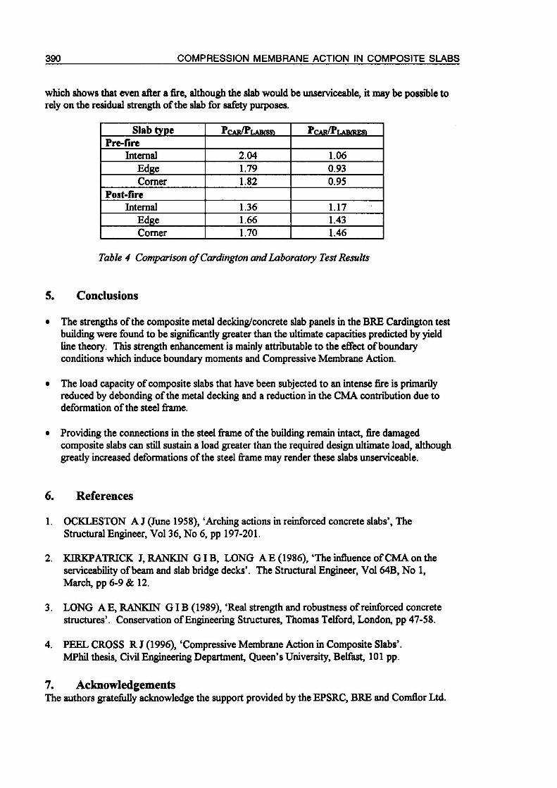
The Cardington test results are compared with the laboratory test results in Table 4. The failureloads for the Cardington slabs are first compared with the failure loads for the simply supportedlaboratory strips. The ratios ofPcar/Plab<ss) show that the strength of real panels tested in-situ
was considerably greater than the conventional simply supported design strength. This strengthenhancement is mainly attributable to the presence of rotational and lateral restraint at the slab
boundaries which gives rise to boundary moments and Compressive Membrane Action. As theinternal panel had the greatest degree of restraint it exhibited the greatest strength enhancement
(except in the post-fire test where the internal panel was the most severely damaged by the fire).
The ratios ofPcar/Plab<res) for the pre-fire tests show that the high degree of restraint used in the
laboratory was close to that of the internal panel at Cardington but was greater than that for theedge and corner panels. The post-fire test results again reflect the more severe damage to theCardington internal panel than the edge and corner panels and also indicate that the edge and
corner panels had greater residual strength than the laboratory results suggested.
All of the slabs exhibited strengths far greater than the ultimate design load of 10.7kN/m2,
390 COMPRESSION MEMBRANE ACTION IN COMPOSITE SLABS
which shows that even after a fire, although the slab would be unserviceable, it may be possible torely on the residual strength of the slab for safety purposes.
Slab type Pcar/Plabts» Pcar/Plakres»Pre-fire
Internal 2.04 1.06
Edge 1.79 0.93Corner 1.82 0.95
Post-fireInternal 1.36 1.17
Edge 1.66 1.43
Corner 1.70 1.46
Table 4 Comparison ofCardington andLaboratory Test Results
5. Conclusions
• The strengths of the composite metal decking/concrete slab panels in the BKE Cardington testbuilding were found to be significantly greater than the ultimate capacities predicted by yieldline theory. This strength enhancement is mainly attributable to the effect ofboundaryconditions which induce boundary moments and Compressive Membrane Action.
• The load capacity of composite slabs that have been subjected to an intense fire is primarilyreduced by debonding of the metal decking and a reduction in the CMA contribution due todeformation of the steel frame.
• Providing the connections in the steel frame of the building remain intact, fire damagedcomposite slabs can still sustain a load greater than the required design ultimate load, althoughgreatly increased deformations of the steel frame may render these slabs unserviceable.
6. References
1. OCKLESTON A J (June 1958), 'Arching actions in reinforced concrete slabs', TheStructural Engineer, Vol 36, No 6, pp 197-201.
2. KIRKPATRICK J, RANKIN GIB, LONG A E (1986), 'The influence ofCMA on the
serviceability ofbeam and slab bridge decks'. The Structural Engineer, Vol 64B, No 1,
March, pp 6-9 & 12.
3. LONG AE, RANKIN GIB (1989),'Real strength and robustness of reinforced concretestructures'. Conservation ofEngineering Structures, Thomas Telford, London, pp 47-58.
4. PEEL CROSS R J (1996),'Compressive Membrane Action in Composite Slabs'.
MPhil thesis, Civil Engineering Department, Queen's University, Belfast, 101 pp.
7. AcknowledgementsThe authors gratefully acknowledge the support provided by the EPSRC, BRE and ComflorLtd.
Related Documents