Page 1865 Compressed Air Vehicle T.Pothuraju M.Tech(T.E) Gokul Group of Institutions, Bobbili. Mr.V.Pradeep Kumar, M.Tech Assistant Professor Gokul Group of Institutions, Bobbili. Abstract: A compressed-air vehicle is powered by an air engine, using compressed air, which is stored in a tank. Instead of mixing fuel with air and burning it in the engine to drive pistons with hot expanding gases, compressed air vehicles (CAV) use the expansion of compressed air to drive their pistons. One manufacturer claims to have designed an engine that is 90 percent efficient. Compressed air propulsion may also be incorporated in hybrid systems, e.g., battery electric propulsion and fuel tanks to recharge the batteries. This kind of system is called hybrid-pneumatic electric propulsion. Additionally, regenerative braking can also be used in conjunction with this system. AIR ENGINE HISTORY Angelo Di Petro’s Rotary Positive Displacement Air Engine:- Everything I've heard about this air engine is positive. Many people have written asking me to report on it, but the show you a picture and a Based on what is said about the engine, I think it sounds like a good idea. It seems like a good approach to simplifying the piston engine while lowering friction and wear. Quoting from the website, "The space between stator and rotor is divided in 6 expansion chambers by pivoting dividers. These dividers follow the motion of the shaft driver as it rolls around the stator wall. The motor shown is effectively a 6 cylinder expansion motor...Variation of performance parameters of the motor is easily achieved by varying the time during which the air is allowed to enter the chamber: A longer air inlet period allows more air to flow into the chamber and therefore results in more torque. A shorter inlet period will limit the air supply and allows the air in the chamber to perform expansion work at a much higher efficiency. In this way compressed air (energy) consumption can be exchanged for higher torque and power output depending on the requirements of the application...Motor speed and torque are simply controlled by throttling the amount or pressure of air into the motor. The Di Pietro motor gives instant torque at zero RPM and can be precisely controlled to give soft start and acceleration control." From what I've read, I think this sounds like what other people have wished they could invent. A lot of people are counting on Mr. Di Pietro to get an air car on the market. Spark Ignition Engine A spark ignition (SI) engine runs on an Otto cycle— most gasoline engines run on a modified Otto cycle. This cycle uses a homogeneous air-fuel mixture which is combined prior to entering the combustion chamber. Once in the combustion chamber, the mixture is compressed, and then ignited using a spark plug (spark ignition). The SI engine is controlled by limiting the

Welcome message from author
This document is posted to help you gain knowledge. Please leave a comment to let me know what you think about it! Share it to your friends and learn new things together.
Transcript
Page 1865
Compressed Air Vehicle
T.Pothuraju
M.Tech(T.E)
Gokul Group of Institutions,
Bobbili.
Mr.V.Pradeep Kumar, M.Tech
Assistant Professor
Gokul Group of Institutions,
Bobbili.
Abstract:
A compressed-air vehicle is powered by an air engine,
using compressed air, which is stored in a tank.
Instead of mixing fuel with air and burning it in the
engine to drive pistons with hot expanding gases,
compressed air vehicles (CAV) use the expansion of
compressed air to drive their pistons. One
manufacturer claims to have designed an engine that
is 90 percent efficient.
Compressed air propulsion may also be incorporated
in hybrid systems, e.g., battery electric propulsion and
fuel tanks to recharge the batteries. This kind of
system is called hybrid-pneumatic electric propulsion.
Additionally, regenerative braking can also be used
in conjunction with this system.
AIR ENGINE HISTORY
Angelo Di Petro’s Rotary Positive Displacement Air
Engine:-
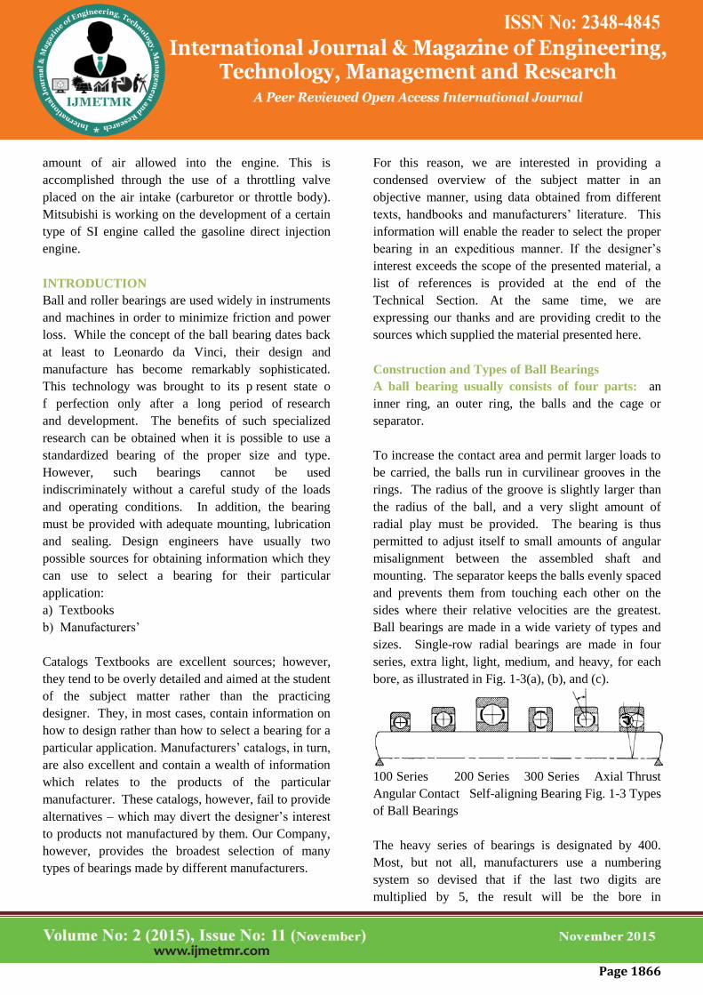
Everything I've heard about this air engine is positive.
Many people have written asking me to report on it,
but the show you a picture and a Based on what is said
about the engine, I think it sounds like a good idea. It
seems like a good approach to simplifying the piston
engine while lowering friction and wear. Quoting
from the website,
"The space between stator and rotor is divided in 6
expansion chambers by pivoting dividers. These
dividers follow the motion of the shaft driver as it rolls
around the stator wall.
The motor shown is effectively a 6 cylinder expansion
motor...Variation of performance parameters of the
motor is easily achieved by varying the time during
which the air is allowed to enter the chamber: A longer
air inlet period allows more air to flow into the
chamber and therefore results in more torque. A
shorter inlet period will limit the air supply and allows
the air in the chamber to perform expansion work at a
much higher efficiency. In this way compressed air
(energy) consumption can be exchanged for higher
torque and power output depending on the
requirements of the application...Motor speed and
torque are simply controlled by throttling the amount
or pressure of air into the motor. The Di Pietro motor
gives instant torque at zero RPM and can be precisely
controlled to give soft start and acceleration control."
From what I've read, I think this sounds like what other
people have wished they could invent. A lot of people
are counting on Mr. Di Pietro to get an air car on the
market.
Spark Ignition Engine
A spark ignition (SI) engine runs on an Otto cycle—
most gasoline engines run on a modified Otto cycle.
This cycle uses a homogeneous air-fuel mixture which
is combined prior to entering the combustion chamber.
Once in the combustion chamber, the mixture is
compressed, and then ignited using a spark plug (spark
ignition). The SI engine is controlled by limiting the
Page 1866
amount of air allowed into the engine. This is
accomplished through the use of a throttling valve
placed on the air intake (carburetor or throttle body).
Mitsubishi is working on the development of a certain
type of SI engine called the gasoline direct injection
engine.
INTRODUCTION
Ball and roller bearings are used widely in instruments
and machines in order to minimize friction and power
loss. While the concept of the ball bearing dates back
at least to Leonardo da Vinci, their design and
manufacture has become remarkably sophisticated.
This technology was brought to its p resent state o
f perfection only after a long period of research
and development. The benefits of such specialized
research can be obtained when it is possible to use a
standardized bearing of the proper size and type.
However, such bearings cannot be used
indiscriminately without a careful study of the loads
and operating conditions. In addition, the bearing
must be provided with adequate mounting, lubrication
and sealing. Design engineers have usually two
possible sources for obtaining information which they
can use to select a bearing for their particular
application:
a) Textbooks
b) Manufacturers’
Catalogs Textbooks are excellent sources; however,
they tend to be overly detailed and aimed at the student
of the subject matter rather than the practicing
designer. They, in most cases, contain information on
how to design rather than how to select a bearing for a
particular application. Manufacturers’ catalogs, in turn,
are also excellent and contain a wealth of information
which relates to the products of the particular
manufacturer. These catalogs, however, fail to provide
alternatives – which may divert the designer’s interest
to products not manufactured by them. Our Company,
however, provides the broadest selection of many
types of bearings made by different manufacturers.
For this reason, we are interested in providing a
condensed overview of the subject matter in an
objective manner, using data obtained from different
texts, handbooks and manufacturers’ literature. This
information will enable the reader to select the proper
bearing in an expeditious manner. If the designer’s
interest exceeds the scope of the presented material, a
list of references is provided at the end of the
Technical Section. At the same time, we are
expressing our thanks and are providing credit to the
sources which supplied the material presented here.
Construction and Types of Ball Bearings
A ball bearing usually consists of four parts: an
inner ring, an outer ring, the balls and the cage or
separator.
To increase the contact area and permit larger loads to
be carried, the balls run in curvilinear grooves in the
rings. The radius of the groove is slightly larger than
the radius of the ball, and a very slight amount of
radial play must be provided. The bearing is thus
permitted to adjust itself to small amounts of angular
misalignment between the assembled shaft and
mounting. The separator keeps the balls evenly spaced
and prevents them from touching each other on the
sides where their relative velocities are the greatest.
Ball bearings are made in a wide variety of types and
sizes. Single-row radial bearings are made in four
series, extra light, light, medium, and heavy, for each
bore, as illustrated in Fig. 1-3(a), (b), and (c).
100 Series 200 Series 300 Series Axial Thrust
Angular Contact Self-aligning Bearing Fig. 1-3 Types
of Ball Bearings
The heavy series of bearings is designated by 400.
Most, but not all, manufacturers use a numbering
system so devised that if the last two digits are
multiplied by 5, the result will be the bore in
Page 1867
millimeters.The digit in the third place from the right
indicates the series number. Thus, bearing 307
signifies a medium-series bearing of 35-mm bore. For
additional digits, which may be present in the catalog
number of a bearing, refer to manufacturer’s details.
Some makers list deep groove bearings and bearings
with two rows of balls. For bearing designations of
Quality Bearings & Components (QBC), see special
pages devoted to this purpose The radial bearing is
able to carry a considerable amount of axial thrust.
However, when the load is directed entirely along the
axis, the thrust type of bearing should be used. The
angular contact bearing will take care of both radial
and axial loads.
The self-aligning ball bearing will take care of
large amounts of angular misalignment. An
increase in radial capacity may be secured by using
rings with deep grooves, or by employing a double-
row radial bearing. Radial bearings are divided into
two general classes, depending on the method of
assembly. These are the Conrad, or non filling-notch
type, and the maximum or filling-notch type. In the
Conrad bearing, the balls are placed between the rings
as shown in Fig. 1-4(a). Then they are evenly spaced
and the separator is riveted in place. In the
maximum-type bearing, the balls are a (a) (b) (c) (d)
(e) (f) 100 Series Extra Light 200 Series Light 300
Series Medium Axial Thrust Bearing Angular Contact
Bearing Self-aligning Bearing Fig. 1-3 Types of Ball
Bearings Fig. 1-4 Methods of Assembly for Ball
Bearings (a) Conrad or non-filling notch type (b)
Maximum or filling notch type
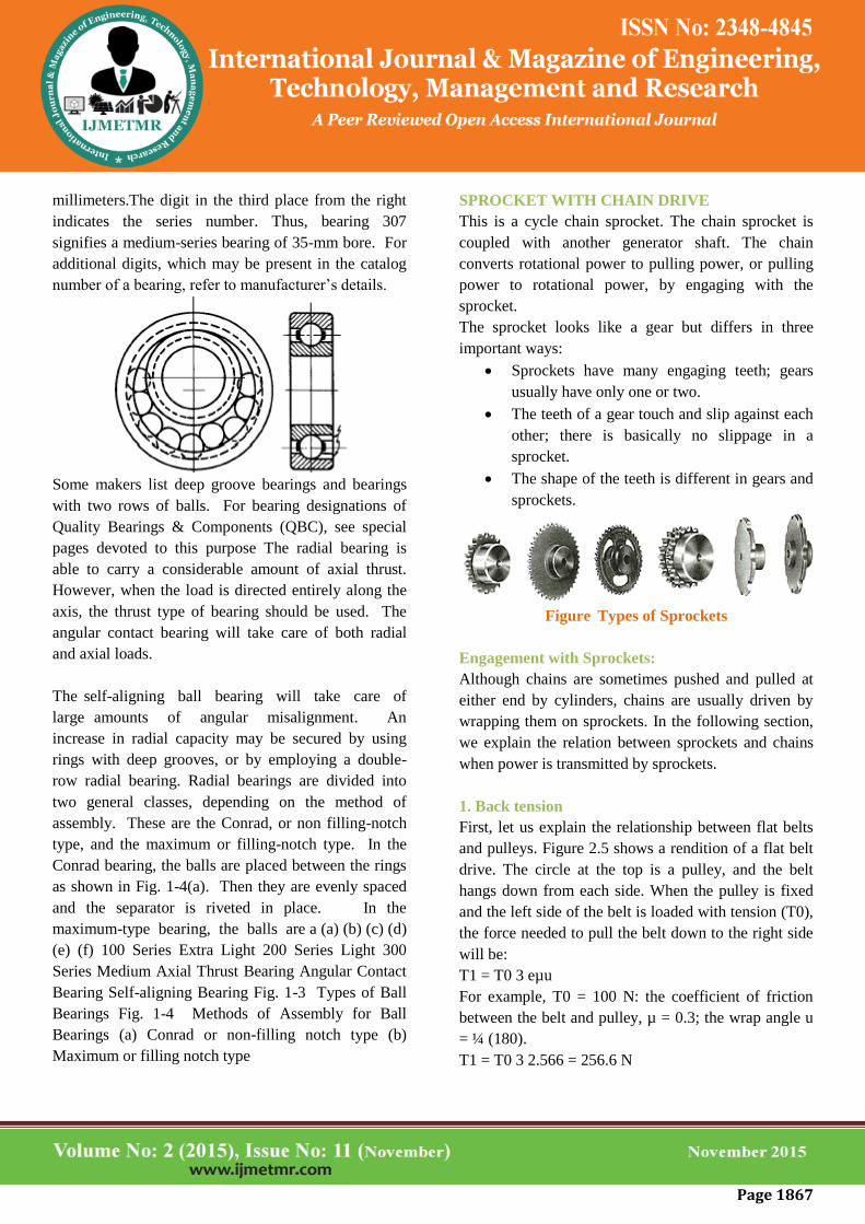
SPROCKET WITH CHAIN DRIVE
This is a cycle chain sprocket. The chain sprocket is
coupled with another generator shaft. The chain
converts rotational power to pulling power, or pulling
power to rotational power, by engaging with the
sprocket.
The sprocket looks like a gear but differs in three
important ways:
Sprockets have many engaging teeth; gears
usually have only one or two.
The teeth of a gear touch and slip against each
other; there is basically no slippage in a
sprocket.
The shape of the teeth is different in gears and
sprockets.
Figure Types of Sprockets
Engagement with Sprockets:
Although chains are sometimes pushed and pulled at
either end by cylinders, chains are usually driven by
wrapping them on sprockets. In the following section,
we explain the relation between sprockets and chains
when power is transmitted by sprockets.
1. Back tension
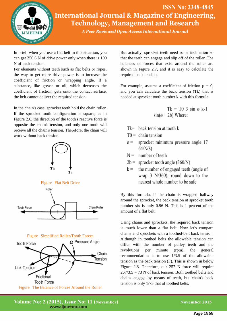
First, let us explain the relationship between flat belts
and pulleys. Figure 2.5 shows a rendition of a flat belt
drive. The circle at the top is a pulley, and the belt
hangs down from each side. When the pulley is fixed
and the left side of the belt is loaded with tension (T0),
the force needed to pull the belt down to the right side
will be:
T1 = T0 3 eµu
For example, T0 = 100 N: the coefficient of friction
between the belt and pulley, µ = 0.3; the wrap angle u
= ¼ (180).
T1 = T0 3 2.566 = 256.6 N
Page 1868
In brief, when you use a flat belt in this situation, you
can get 256.6 N of drive power only when there is 100
N of back tension.
For elements without teeth such as flat belts or ropes,
the way to get more drive power is to increase the
coefficient of friction or wrapping angle. If a
substance, like grease or oil, which decreases the
coefficient of friction, gets onto the contact surface,
the belt cannot deliver the required tension.
In the chain's case, sprocket teeth hold the chain roller.
If the sprocket tooth configuration is square, as in
Figure 2.6, the direction of the tooth's reactive force is
opposite the chain's tension, and only one tooth will
receive all the chain's tension. Therefore, the chain will
work without back tension.
Figure Flat Belt Drive
Figure Simplified Roller/Tooth Forces
Figure The Balance of Forces Around the Roller
But actually, sprocket teeth need some inclination so
that the teeth can engage and slip off of the roller. The
balances of forces that exist around the roller are
shown in Figure 2.7, and it is easy to calculate the
required back tension.
For example, assume a coefficient of friction µ = 0,
and you can calculate the back tension (Tk) that is
needed at sprocket tooth number k with this formula:
By this formula, if the chain is wrapped halfway
around the sprocket, the back tension at sprocket tooth
number six is only 0.96 N. This is 1 percent of the
amount of a flat belt.
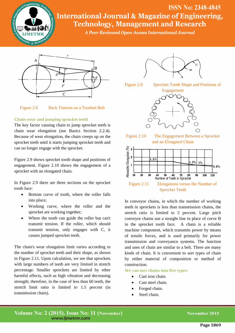
Using chains and sprockets, the required back tension
is much lower than a flat belt. Now let's compare
chains and sprockets with a toothed-belt back tension.
Although in toothed belts the allowable tension can
differ with the number of pulley teeth and the
revolutions per minute (rpm), the general
recommendation is to use 1/3.5 of the allowable
tension as the back tension (F). This is shown in below
Figure 2.8. Therefore, our 257 N force will require
257/3.5 = 73 N of back tension. Both toothed belts and
chains engage by means of teeth, but chain's back
tension is only 1/75 that of toothed belts.
Page 1869
Figure 2.8 Back Tension on a Toothed Belt
Chain wear and jumping sprocket teeth
The key factor causing chain to jump sprocket teeth is
chain wear elongation (see Basics Section 2.2.4).
Because of wear elongation, the chain creeps up on the
sprocket teeth until it starts jumping sprocket teeth and
can no longer engage with the sprocket.
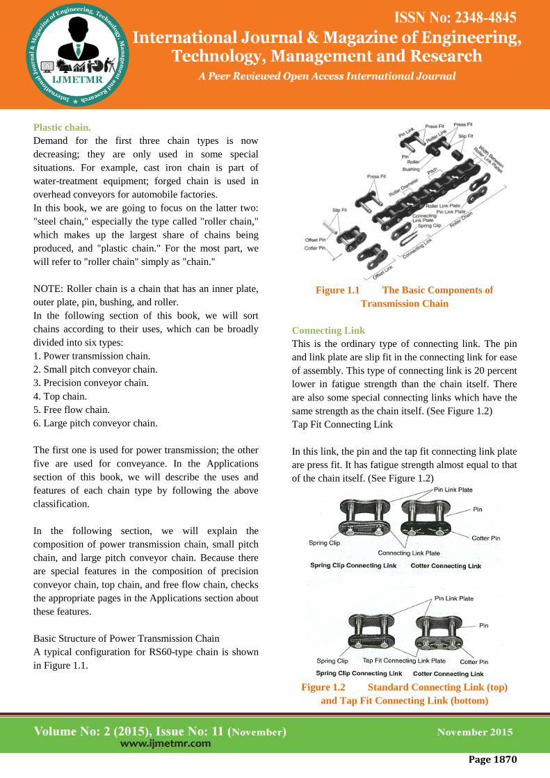
Figure 2.9 shows sprocket tooth shape and positions of
engagement. Figure 2.10 shows the engagement of a
sprocket with an elongated chain.
In Figure 2.9 there are three sections on the sprocket
tooth face:
Bottom curve of tooth, where the roller falls
into place;
Working curve, where the roller and the
sprocket are working together;
Where the tooth can guide the roller but can't
transmit tension. If the roller, which should
transmit tension, only engages with C, it
causes jumped sprocket teeth.
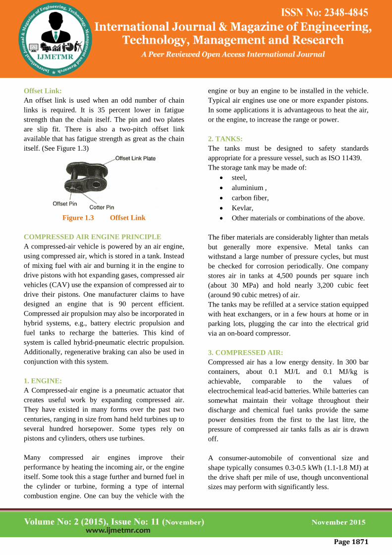
The chain's wear elongation limit varies according to
the number of sprocket teeth and their shape, as shown
in Figure 2.11. Upon calculation, we see that sprockets
with large numbers of teeth are very limited in stretch
percentage. Smaller sprockets are limited by other
harmful effects, such as high vibration and decreasing
strength; therefore, in the case of less than 60 teeth, the
stretch limit ratio is limited to 1.5 percent (in
transmission chain).
Figure 2.9 Sprocket Tooth Shape and Positions of
Engagement
Figure 2.10 The Engagement Between a Sprocket
and an Elongated Chain
Figure 2.11 Elongations versus the Number of
Sprocket Teeth
In conveyor chains, in which the number of working
teeth in sprockets is less than transmission chains, the
stretch ratio is limited to 2 percent. Large pitch
conveyor chains use a straight line in place of curve B
in the sprocket tooth face. A chain is a reliable
machine component, which transmits power by means
of tensile forces, and is used primarily for power
transmission and conveyance systems. The function
and uses of chain are similar to a belt. There are many
kinds of chain. It is convenient to sort types of chain
by either material of composition or method of
construction.
We can sort chains into five types:
Cast iron chain.
Cast steel chain.
Forged chain.
Steel chain.
Page 1870
Plastic chain.
Demand for the first three chain types is now
decreasing; they are only used in some special
situations. For example, cast iron chain is part of
water-treatment equipment; forged chain is used in
overhead conveyors for automobile factories.
In this book, we are going to focus on the latter two:
"steel chain," especially the type called "roller chain,"
which makes up the largest share of chains being
produced, and "plastic chain." For the most part, we
will refer to "roller chain" simply as "chain."
NOTE: Roller chain is a chain that has an inner plate,
outer plate, pin, bushing, and roller.
In the following section of this book, we will sort
chains according to their uses, which can be broadly
divided into six types:
1. Power transmission chain.
2. Small pitch conveyor chain.
3. Precision conveyor chain.
4. Top chain.
5. Free flow chain.
6. Large pitch conveyor chain.
The first one is used for power transmission; the other
five are used for conveyance. In the Applications
section of this book, we will describe the uses and
features of each chain type by following the above
classification.
In the following section, we will explain the
composition of power transmission chain, small pitch
chain, and large pitch conveyor chain. Because there
are special features in the composition of precision
conveyor chain, top chain, and free flow chain, checks
the appropriate pages in the Applications section about
these features.
Basic Structure of Power Transmission Chain
A typical configuration for RS60-type chain is shown
in Figure 1.1.
Figure 1.1 The Basic Components of
Transmission Chain
Connecting Link
This is the ordinary type of connecting link. The pin
and link plate are slip fit in the connecting link for ease
of assembly. This type of connecting link is 20 percent
lower in fatigue strength than the chain itself. There
are also some special connecting links which have the
same strength as the chain itself. (See Figure 1.2)
Tap Fit Connecting Link
In this link, the pin and the tap fit connecting link plate
are press fit. It has fatigue strength almost equal to that
of the chain itself. (See Figure 1.2)
Figure 1.2 Standard Connecting Link (top)
and Tap Fit Connecting Link (bottom)
Page 1871
Offset Link:
An offset link is used when an odd number of chain
links is required. It is 35 percent lower in fatigue
strength than the chain itself. The pin and two plates
are slip fit. There is also a two-pitch offset link
available that has fatigue strength as great as the chain
itself. (See Figure 1.3)
Figure 1.3 Offset Link
COMPRESSED AIR ENGINE PRINCIPLE
A compressed-air vehicle is powered by an air engine,
using compressed air, which is stored in a tank. Instead
of mixing fuel with air and burning it in the engine to
drive pistons with hot expanding gases, compressed air
vehicles (CAV) use the expansion of compressed air to
drive their pistons. One manufacturer claims to have
designed an engine that is 90 percent efficient.
Compressed air propulsion may also be incorporated in
hybrid systems, e.g., battery electric propulsion and
fuel tanks to recharge the batteries. This kind of
system is called hybrid-pneumatic electric propulsion.
Additionally, regenerative braking can also be used in
conjunction with this system.
1. ENGINE:
A Compressed-air engine is a pneumatic actuator that
creates useful work by expanding compressed air.
They have existed in many forms over the past two
centuries, ranging in size from hand held turbines up to
several hundred horsepower. Some types rely on
pistons and cylinders, others use turbines.
Many compressed air engines improve their
performance by heating the incoming air, or the engine
itself. Some took this a stage further and burned fuel in
the cylinder or turbine, forming a type of internal
combustion engine. One can buy the vehicle with the
engine or buy an engine to be installed in the vehicle.
Typical air engines use one or more expander pistons.
In some applications it is advantageous to heat the air,
or the engine, to increase the range or power.
2. TANKS:
The tanks must be designed to safety standards
appropriate for a pressure vessel, such as ISO 11439.
The storage tank may be made of:
steel,
aluminium ,
carbon fiber,
Kevlar,
Other materials or combinations of the above.
The fiber materials are considerably lighter than metals
but generally more expensive. Metal tanks can
withstand a large number of pressure cycles, but must
be checked for corrosion periodically. One company
stores air in tanks at 4,500 pounds per square inch
(about 30 MPa) and hold nearly 3,200 cubic feet
(around 90 cubic metres) of air.
The tanks may be refilled at a service station equipped
with heat exchangers, or in a few hours at home or in
parking lots, plugging the car into the electrical grid
via an on-board compressor.
3. COMPRESSED AIR:
Compressed air has a low energy density. In 300 bar
containers, about 0.1 MJ/L and 0.1 MJ/kg is
achievable, comparable to the values of
electrochemical lead-acid batteries. While batteries can
somewhat maintain their voltage throughout their
discharge and chemical fuel tanks provide the same
power densities from the first to the last litre, the
pressure of compressed air tanks falls as air is drawn
off.
A consumer-automobile of conventional size and
shape typically consumes 0.3-0.5 kWh (1.1-1.8 MJ) at
the drive shaft per mile of use, though unconventional
sizes may perform with significantly less.
Page 1872
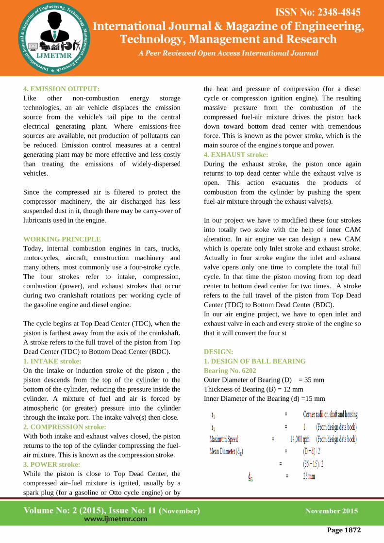
4. EMISSION OUTPUT:
Like other non-combustion energy storage
technologies, an air vehicle displaces the emission
source from the vehicle's tail pipe to the central
electrical generating plant. Where emissions-free
sources are available, net production of pollutants can
be reduced. Emission control measures at a central
generating plant may be more effective and less costly
than treating the emissions of widely-dispersed
vehicles.
Since the compressed air is filtered to protect the
compressor machinery, the air discharged has less
suspended dust in it, though there may be carry-over of
lubricants used in the engine.
WORKING PRINCIPLE
Today, internal combustion engines in cars, trucks,
motorcycles, aircraft, construction machinery and
many others, most commonly use a four-stroke cycle.
The four strokes refer to intake, compression,
combustion (power), and exhaust strokes that occur
during two crankshaft rotations per working cycle of
the gasoline engine and diesel engine.
The cycle begins at Top Dead Center (TDC), when the
piston is farthest away from the axis of the crankshaft.
A stroke refers to the full travel of the piston from Top
Dead Center (TDC) to Bottom Dead Center (BDC).
1. INTAKE stroke:
On the intake or induction stroke of the piston , the
piston descends from the top of the cylinder to the
bottom of the cylinder, reducing the pressure inside the
cylinder. A mixture of fuel and air is forced by
atmospheric (or greater) pressure into the cylinder
through the intake port. The intake valve(s) then close.
2. COMPRESSION stroke:
With both intake and exhaust valves closed, the piston
returns to the top of the cylinder compressing the fuel-
air mixture. This is known as the compression stroke.
3. POWER stroke:
While the piston is close to Top Dead Center, the
compressed air–fuel mixture is ignited, usually by a
spark plug (for a gasoline or Otto cycle engine) or by
the heat and pressure of compression (for a diesel
cycle or compression ignition engine). The resulting
massive pressure from the combustion of the
compressed fuel-air mixture drives the piston back
down toward bottom dead center with tremendous
force. This is known as the power stroke, which is the
main source of the engine's torque and power.
4. EXHAUST stroke:
During the exhaust stroke, the piston once again
returns to top dead center while the exhaust valve is
open. This action evacuates the products of
combustion from the cylinder by pushing the spent
fuel-air mixture through the exhaust valve(s).
In our project we have to modified these four strokes
into totally two stoke with the help of inner CAM
alteration. In air engine we can design a new CAM
which is operate only Inlet stroke and exhaust stroke.
Actually in four stroke engine the inlet and exhaust
valve opens only one time to complete the total full
cycle. In that time the piston moving from top dead
center to bottom dead center for two times. A stroke
refers to the full travel of the piston from Top Dead
Center (TDC) to Bottom Dead Center (BDC).
In our air engine project, we have to open inlet and
exhaust valve in each and every stroke of the engine so
that it will convert the four st
DESIGN:
1. DESIGN OF BALL BEARING
Bearing No. 6202
Outer Diameter of Bearing (D) = 35 mm
Thickness of Bearing (B) = 12 mm
Inner Diameter of the Bearing (d) =15 mm

Page 1873
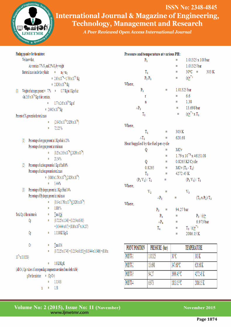
1. ENGINE DESIGN CALCULATIONS:-
DESIGN AND ANYLSIS ON TEMPERATURE
DISTRIBUTION FOR TWO-STROKE ENGINE
COMPONENT USING FINITE ELEMENT
METHOD:
SPECIFICATION OF FOUR STROKE PETROL
ENGINE:
Page 1874

Page 1875
Page 1876
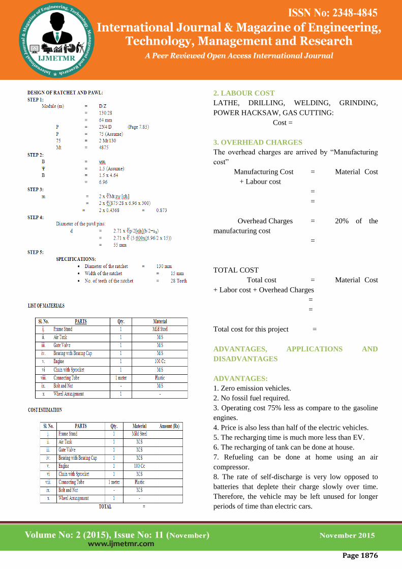
2. LABOUR COST
LATHE, DRILLING, WELDING, GRINDING,
POWER HACKSAW, GAS CUTTING:
Cost =
3. OVERHEAD CHARGES
The overhead charges are arrived by “Manufacturing
cost”
Manufacturing Cost = Material Cost
+ Labour cost
=
=
Overhead Charges = 20% of the
manufacturing cost
=
TOTAL COST
Total cost = Material Cost
+ Labor cost + Overhead Charges
=
=
Total cost for this project =
ADVANTAGES, APPLICATIONS AND
DISADVANTAGES
ADVANTAGES:
1. Zero emission vehicles.
2. No fossil fuel required.
3. Operating cost 75% less as compare to the gasoline
engines.
4. Price is also less than half of the electric vehicles.
5. The recharging time is much more less than EV.
6. The recharging of tank can be done at house.
7. Refueling can be done at home using an air
compressor.
8. The rate of self-discharge is very low opposed to
batteries that deplete their charge slowly over time.
Therefore, the vehicle may be left unused for longer
periods of time than electric cars.
Page 1877
APPLICATIONS
1. Two wheeler Application
2. Four wheeler Applications
DISADVANTAGES
1. It can’t give much higher speed.
2. The recharging stations are not available.
3. Tanks get very hot when filled rapidly. It very
dangers it sometime bloused
CONCLUSION
This project work has provided us an excellent
opportunity and experience, to use our limited
knowledge. We gained a lot of practical knowledge
regarding, planning, purchasing, assembling and
machining while doing this project work. We feel that
the project work is a good solution to bridge the gates
between institution and industries.
We are proud that we have completed the work with
the limited time successfully. The AIR ENGINE is
working with satisfactory conditions. We are able to
understand the difficulties in maintaining the
tolerances and also quality. We have done to our
ability and skill making maximum use of available
facilities.
In conclusion remarks of our project work, let us add a
few more lines about our impression project work.
Thus we have developed an “AIR ENGINE” which
helps to know how to achieve compressed air vehicle.
The application of pneumatics produces smooth
operation. By using more techniques, they can be
modified and developed according to the applications.
BIBLIOGRAPHY
1 AUTOMOBILE ENGG. - N.M AGGARWAL
S.K.KATARIA & SONS
2 ADVANCES IN AUTOMOBILE ENGG. -
S.SUBRAMANIAM ALLIED PUBLISHERS LTD.
3 THEORY & PERFORMANCE OF ELECTRICAL
MACHINES - J.B.GUPTA S.K.KATARIA & SONS
4 PRINCIPLES OF ELECTRICAL ENGINEERING
AND ELECTRONICS - V.K.METHTA
Related Documents