Compound Heat Transfer Enhancement Methods To Increase Heat Exchanger Efficiency David J. Kukulka State University of New York College at Buffalo USA [email protected] Rick Smith Vipertex Division of Rigidized Metals, Inc Buffalo, New York USA

Welcome message from author
This document is posted to help you gain knowledge. Please leave a comment to let me know what you think about it! Share it to your friends and learn new things together.
Transcript

Compound Heat Transfer
Enhancement Methods To
Increase Heat Exchanger
Efficiency David J. Kukulka State University of New York College at Buffalo USA
Rick Smith
Vipertex Division of Rigidized Metals, Inc
Buffalo, New York USA

Problem
This study details the process of evaluating a
compound enhanced heat transfer tube.
Compound enhanced heat transfer tubes utilizes more
than one enhancement method (tubes and twisted
tapes) to change heat transfer
In order to design the compound enhanced heat
transfer tube, a fluid flow model of the tube and
twisted tape was created and studied.
Experimentation on the system validated the design
CAPE 2012 Introduction Procedure Results Conclusion 2

Outline Introduction
Waste Heat
Enhanced heat transfer surface background
Benefits
Design Considerations
Enhancement Techniques
Twisted Tapes
Compound Heat Transfer
Previous Work
Procedure
Results
Conclusions
3 CAPE 2012 Introduction Procedure Results Conclusion

4

Potential of Waste Heat
5
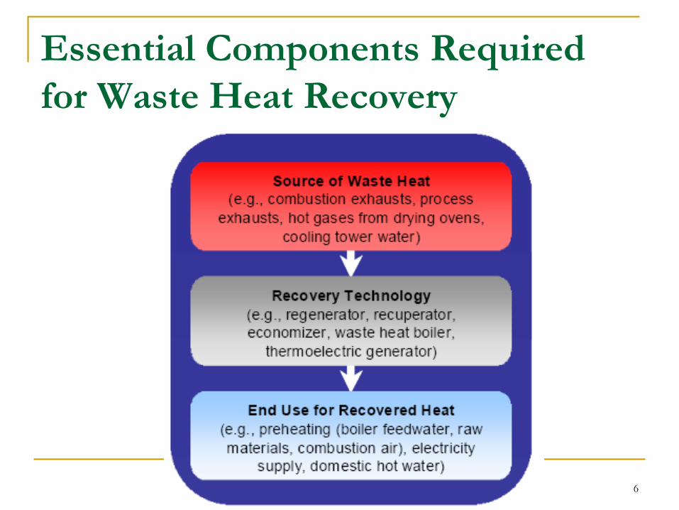
Essential Components Required
for Waste Heat Recovery
6

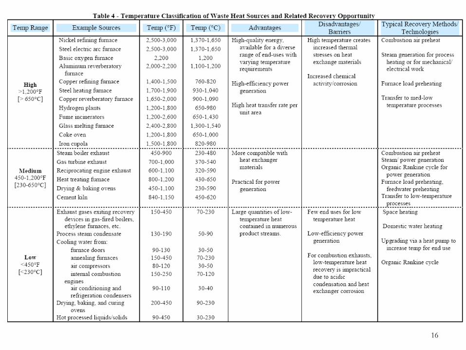
Important Concepts that Determine Waste
Heat Recovery Feasibility
The quantity of waste heat contained in a waste stream is
a function of both the temperature and the mass flow rate
of the stream.
Waste Heat Temperature is a key factor determining
waste heat recovery feasibility and can vary significantly.
Typical Examples of Waste Temperatures:
Cooling Water - Low temperatures around 100 - 200°F [40 - 90°C]
Glass Melting Furnaces - Flue temperatures above 2400°F [1320°C].
7

Sources of Waste Heat Users of Waste Heat
8

Important Parameters that Determine
Materials for Use in Waste Heat Recovery
Temperature of the waste heat source is important for
material selection in heat exchangers or a heat recovery
system
Composition of the stream affects the recovery process
and material selection.
The composition and phase of waste heat streams will impact
heat exchanger effectiveness.
9

Waste Heat Temperature Groups
High : 1200ºF [650°C]
Medium: 450ºF [230°C] to 1200ºF [650°C]
Low: 450ºF [230°C] and lower
10

Waste Heat Potential from Selected Processes
11
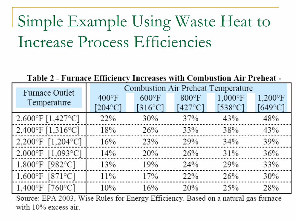
Simple Example Using Waste Heat to
Increase Process Efficiencies
12
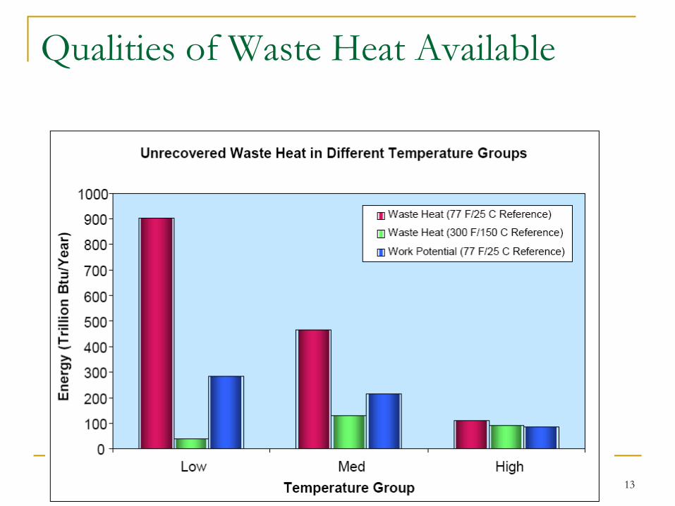
Qualities of Waste Heat Available
13

Waste Heat Content for Selected
Processes
14
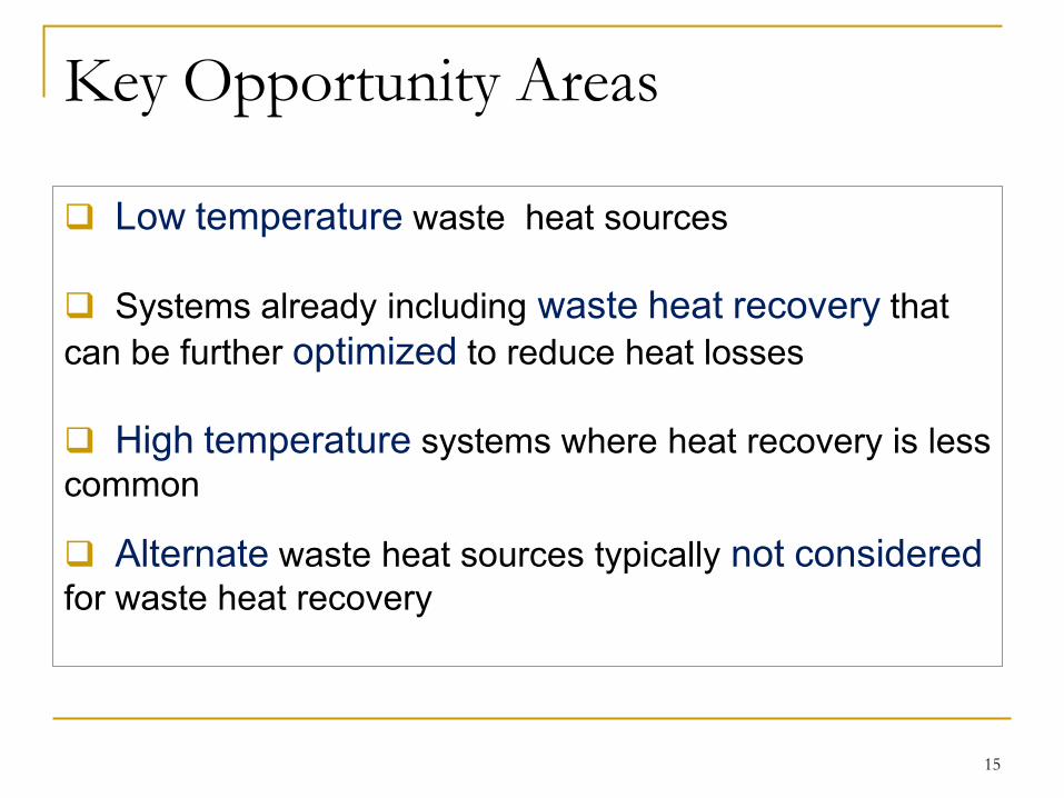
Key Opportunity Areas
Low temperature waste heat sources
Systems already including waste heat recovery that
can be further optimized to reduce heat losses
High temperature systems where heat recovery is less
common
Alternate waste heat sources typically not considered
for waste heat recovery
15
16

Waste Heat Potential as a Function of Furnace Size
17

Waste Heat Loss in the Glass Industry
18

Enhanced Heat Transfer Surfaces
Enhanced Surfaces have developed a great
deal of interest in the design of heat
exchange devices .
Various areas in industry are currently
working aggressively to incorporate enhanced
heat transfer surface technology into their
designs.
Virtually every heat exchange device is a potential
candidate for enhanced heat transfer.
19 CAPE 2012 Introduction Procedure Results Conclusion
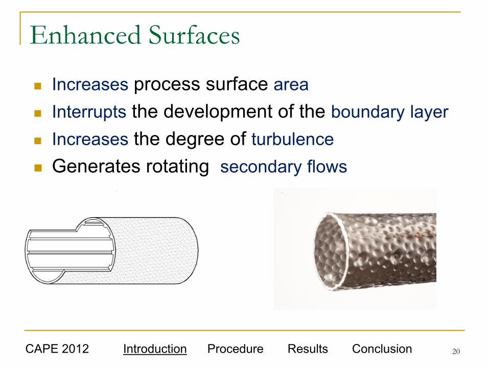
Enhanced Surfaces
Increases process surface area
Interrupts the development of the boundary layer
Increases the degree of turbulence
Generates rotating secondary flows
CAPE 2012 Introduction Procedure Results Conclusion 20

Enhanced Surface Ratio
Ratio of h A of the enhanced surface to that
of a plain surface is the enhancement ratio.
PLAIN
ENHANCED
hA
hAtRatioEnhancemen
)(
)(
CAPE 2012 Introduction Procedure Results Conclusion
Heat
Transfer
Coefficient
Surface
Area
21

Overall Thermal Resistance
222111 Ah
L
Ak
Lt
Ah
L
UA
L
mw
w
Surface efficiency, if extended surfaces are used
•The performance of the heat exchanger will be enhanced if UA/L is increased.
• Enhanced Heat Transfer Surfaces Reduces the thermal resistance per unit length.
• Fouling Resistance may also be added in this calculation.
Subscripts 1 and 2
refer to inside fluid
and outside fluid
CAPE 2012 Introduction Procedure Results Conclusion 22

Parameters to Characterize Surface
Enhancements for this Study
Enhance Heat Transfer • Geometry of the roughness should break the laminar sub layer.
• Minimize disruption to the core in order to keep pressure drop within
range.
Several Enhancement Geometries to Consider: • Rib, Rectangular, Circular, Dimples, Grooves, Wedges, etc.
Surface Enhancement Arrangements to Consider: •Continuous, Staggered, Cavity, Groove, etc
CAPE 2012 Introduction Procedure Results Conclusion 23
Previous Geometry Enhancement
Investigations
• Several investigators have attempted to develop
accurate predictions of heat transfer coefficients and
friction factors for compound heat transfer tubes
• Little has been done in the design of twisted tape
surfaces in combination with enhanced tube
surfaces that are designed to enhance heat transfer
near a enhanced tube wall.
CAPE 2012 Introduction Procedure Results Conclusion 24

Enhanced Heat Transfer Surfaces Can be Used to
Provide Performance Improvements
Size Reduction If the rate of heat exchange (Q) is held constant, the
required length (L) of heat exchange may be reduced.
Increased Heat Transfer Rate If Q and the tube length (L) are held constant, ΔTm may be
reduced and the operating costs are reduced.
For fixed fluid inlet temperatures, L constant, and increase in UA/L will result in an increased heat exchange rate (Q).
Reduced power requirements Result of lower required flow rates.
CAPE 2012 Introduction Procedure Results Conclusion 25

Heat Exchanger Size as a Function of
Enhanced Heat Transfer Coefficient
26

Enhancement Techniques
Surface Enhancement Techniques can be segregated into passive and active categories.
Passive techniques employ techniques such as
special surface geometries, coatings or fluid additives.
Active techniques require external devices to enhance
heat transfer.
The concentration here will be on Passive Enhancement.
CAPE 2012 Introduction Procedure Results Conclusion 27

Passive Techniques
Coated surfaces Non Wetting Coating (Teflon) Applied to Promote
Dropwise Condensation
Fine Scale Porous Coating Applied to the Surface to Nucleate Boiling.
Rough Surfaces May be Integral to the Base Surface
machining
restructuring the surface
Enhancement can also be created by placing a roughness adjacent to the surface.
CAPE 2012 Introduction Procedure Results Conclusion 28

Two Fluid Tubular Enhanced
Heat Transfer Tubes are used in typical Heat Exchange Devices.
Enhancement may be desired on both the inner and outer surfaces.
Surface Enhancement Depends on the Application i.e. two phase flow may occur on one side and convection
cooling on the other side.
A variety of techniques are available to enhance heat transfer.
CAPE 2012 Introduction Procedure Results Conclusion 29

Surface Enhancement
Some Techniques Utilize the removal of
material to create an enhanced surface.
That technique may weaken the wall of the tube.
Material dependent.
The technique used in this study redistributed
the material
CAPE 2012 Introduction Procedure Results Conclusion 30
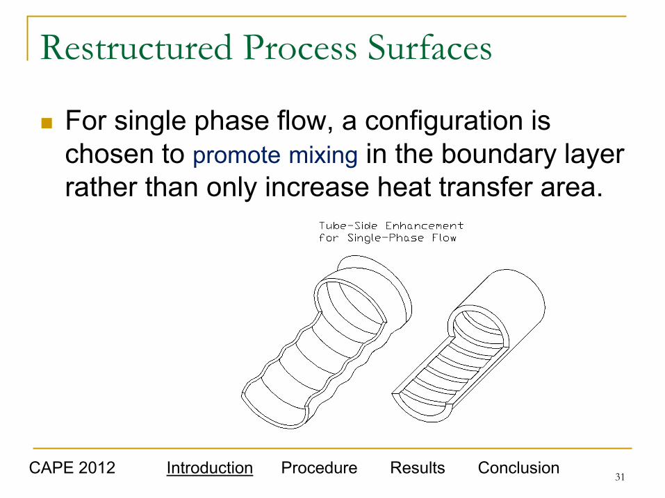
Restructured Process Surfaces
For single phase flow, a configuration is
chosen to promote mixing in the boundary layer
rather than only increase heat transfer area.
CAPE 2012 Introduction Procedure Results Conclusion 31

Tube Side Enhancements
Conventionally Produced Internally Finned
Tubes having high fins are:
quite expensive to produce
difficult to work with
Only select materials
Less Expensive Micro Fin
tubes are only available for
limited materials.
CAPE 2012 Introduction Procedure Results Conclusion 32

Design Variables to Consider
If the process is heating it may have a
different exchange process than if it is a
cooling process.
Laminar, transitional and turbulent flows have
different enhancement requirements.
Single Phase or Two Phase Flow also has
different enhancement requirements.
CAPE 2012 Introduction Procedure Results Conclusion 33

Corrugated Tube Flow
Ravigururajan and Bergles (1986)
summarized work done on various
types of corrugated tubes.
Blumenkrantz and Taborek (1971)
evaluated spirally indented tubes.
Ravigururaian, T. S., and Bergles, A. E., 1986. “An Experimental Verification of General
Correlations for Single-Phase Turbulent Flow in Ribbed Tubes,” in Advances in Heat
Exchanger Design, HTD-Vol. 66, ASME., New York, pp. 1-11.
Blumenkrantz, A., and Taborek, J., 1971. “Heat Transfer and Pressure Drop
Characteristics of Turbotec Spirally Deep Grooved Tubes in the Laminar and Transition
Regime,” Report 2439-300-8, April 1971, Heat Transfer Research, Inc.
CAPE 2012 Introduction Procedure Results Conclusion 34

Enhancement of Laminar Flow in
Roughened Circular Tubes Vicente et al. (2002 a, b) presents laminar flow data
for dimpled tubes.
Enhancement is influenced by several factors
Thermal boundary conditions
Entrance region effects
Natural Convection
Vicente, P. G., García, A., and Viedma, A., 2002. “Experimental Study of Mixed
Convection and Pressure Drop in Helically Dimpled Tubes for Laminar and Transition
Flow,” Int. J. Heat Mass Trans., Vol. 45, pp. 5091-5105.
Vicente, P. G., García, A., and Viedma, A., 2002. “Heat Transfer and Pressure Drop for
Low Reynolds Turbulent Flow in Helically Dimpled Tubes,” Int. J. Heat Mass Trans.,
Vol. 45, pp. 543-553.
CAPE 2012 Introduction Procedure Results Conclusion 35

Dimpled Tubes
Chen et al. (2001) studied inward-facing, raised dimples on the inner tube.
Values of the heat transfer coefficient increased when compared to smooth tubes. Heat transfer enhancement ranged from 25% to 137% at constant
Reynolds number.
Study in the turbulent range
Enhancement increased from 15% to 84% with constant pumping power
Chen, J., Müller-Steinhagen, H., and Duffy, G. G., 2001. “Heat
Transfer Enhancement in Dimpled Tubes,” Applied Thermal Eng. , Vol.
21, pp. 535-547.
CAPE 2012 Introduction Procedure Results Conclusion 36

Enhanced Tubes Evaluated Brahim et al. Numerical Simulation of Fouling, 2003 ECI Conference on Heat Exchanger Fouling
CAPE 2012 Introduction Procedure Results Conclusion 37

CFD
Analysis
of
Various
Surfaces
CAPE 2012 Introduction Procedure Results Conclusion 38

Vipertex EHT Development Included
a Primary Texture Evaluation
In Line Staggered
39 CAPE 2012 Introduction Procedure Results Conclusion

Primary Texture Variation
40 CAPE 2012 Introduction Procedure Results Conclusion
Inside Tube Outside Tube

Secondary Wall Enhancements
41
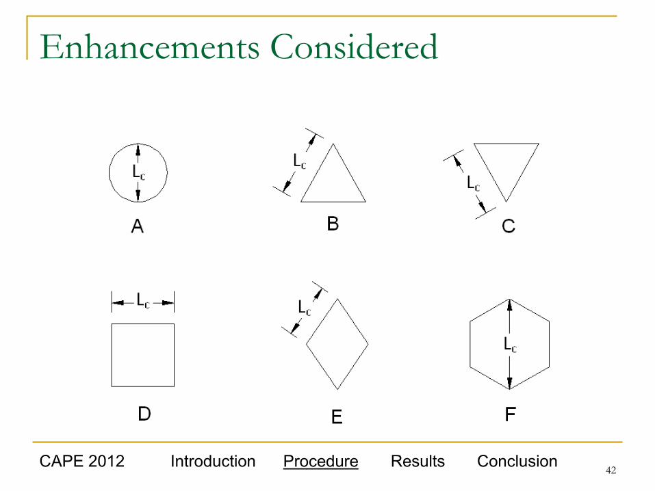
Enhancements Considered
42 CAPE 2012 Introduction Procedure Results Conclusion
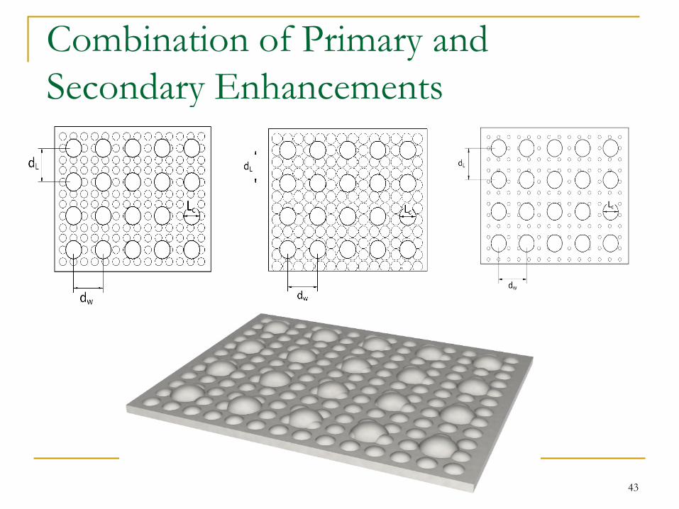
Combination of Primary and
Secondary Enhancements
43

Models of Smooth Tubes current study
CAPE 2012 Introduction Procedure Results Conclusion
Max 0.132
44

Model of a Linear Rib Enhancements
in an Enhanced Tube
CAPE 2012 Introduction Procedure Results Conclusion
Max 0.198
45

Model of Enhanced Structures in Tubes
CAPE 2012 Introduction Procedure Results Conclusion
Max 0.184
46

Typical Enhanced Surface Pattern
Produced for Vipertex 2EHT Tube
48 CAPE 2012 Introduction Procedure Results Conclusion
Outside Inside

Typical Enhanced Tube Produced
CAPE 2012 Introduction Procedure Results Conclusion 49

1EHT Tube Produced
50 CAPE 2012 Introduction Procedure Results Conclusion
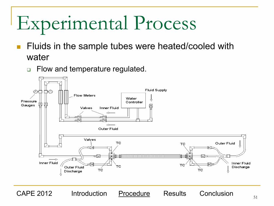
Experimental Process Fluids in the sample tubes were heated/cooled with
water
Flow and temperature regulated.
CAPE 2012 Introduction Procedure Results Conclusion 51

Tube in Tube, Counterflow Test Apparatus
CAPE 2012 Introduction Procedure Results Conclusion 52

Details of Tubes Evaluated
Description Surface Cross Sectional View
(a) Vipertube 2EHT: Type
304 stainless steel
(b) Vipertube 1EHT: Type
304 stainless steel
(c) Stainless steel
smooth tube: Type 304,
type D finish,
CAPE 2012 Introduction Procedure Results Conclusion 53

Tube Enhancement Test Conditions
54

Vipertex 1EHT Enhanced Tubes
55

Vipertex 2EHT Enhanced Tubes
56

Vipertex 1EHT Cooling Enhancement Ratio
57
0.0
1.0
2.0
3.0
4.0
5.0
6.0
7.0
1.00E+01 1.00E+02 1.00E+03 1.00E+04 1.00E+05
Nu
meas / N
up
red
,PT
Re
1EHT - Cooling
Predicted - VDI
Predicted - Ghajar

Vipertex 2EHT Cooling Enhancement Ratio
58
0.0
1.0
2.0
3.0
4.0
5.0
6.0
1.00E+01 1.00E+02 1.00E+03 1.00E+04 1.00E+05
Nu
meas / N
up
red
,PT
Re
2EHT - Cooling
Predicted - VDI
Predicted - Ghajar

Inside Heat Transfer Coefficient Equation for
Enhanced Tubes (1EHT) compared to Smooth Tubes
59
Smooth tube
CAPE 2012 Introduction Procedure Results Conclusion

Friction Factor of Enhanced Tubes (1EHT) Compared to Smooth Tubes
60
Smooth tube
CAPE 2012 Introduction Procedure Results Conclusion

Twisted Tape Inserts
Inserts influence the fluid flow.
Fluid moves with a higher velocity and produces
secondary flows.
Tangential velocity component moves the inner
core fluid closer to the wall for a better exchange
of energy.
Twisted tape inserts force the fluid to follow a
helical path rather than a straight path.
61

Flow Near the Wall
Swirl flow from the twisted tape:
Induces the turbulence near the tube wall
Increases the residence time of the fluid flow in the
tube.
Higher fluid turbulence caused by twisted
tapes close to the tube wall increases
convective heat transfer.
Results in an effective energy enhancing device.
Increases pressure drop (moderate increases)
62
Twisted Tape Advantages
Insertion of twisted tape is one of the most
popular passive heat transfer enhancement
techniques:
Low cost
Ease of installation
Low maintenance
Can be installed on new or existing exchangers
63

Twisted Tapes
Flow enhancements are possible in the laminar
and transitional flow regimes.
The heat transfer and pressure drop
characteristics can be varied somewhat by
changing the twist pitch of the device.
65

Laminar Flow
Laminar Flow is a relatively complex subject
Flow is influenced by :
Thermal boundary conditions
Entrance region effects
Natural convection at low Re
Fluid property variation across the boundary layer
Cross sectional shape
66

Twisted Tape in Smooth Tube with Laminar Flow
for a Twist Ratio of 5 and Various Spacing
67

Shift Region of Maximum Heat Transfer
Through the use of twisted tapes the Reynolds
Number of maximum enhancement can be shifted.
The type of twisted tape has an influence both on the
peak enhancement as well as the magnitude of the
enhancement.
70

Parameters that influence heat transfer
in twisted tapes
Heat Transfer is influence by:
entrance effect
fluid viscosity
ratio (bulk to wall conditions)
Prandtl number
tape twist ratio
swirl flow Reynolds number.
71

Fit of the Twisted Tape also
Influences Enhancement Lopina and Bergles (1969) developed a
practical correlation that includes the influence
of tape width on heat transfer in turbulent
flows.
They reported an increase in the Nusselt number
as much as 20% for the tight-fit tape over that of
the loose-fit tape.
72
Lopina, R. F. and Bergles, A. E. 1969. Heat transfer and
pressure drop in tape generated swirl flow of single-phase
water. J. Heat Transfer, 91, 434-442

Optimum Tape Width
Ayub and AI-Fahed (1993) have conducted
extensive experimental research on the
influence of twisted tape width on the
pressure drop.
Existence of an optimum tape width
Function of both the twist ratio and the Reynolds
numbers.
73
Ayub, Z. H. and AI-Fahed, S. F. 1993. The effect of gap width
between horizontal tube and twisted tape on the pressure drop in
turbulent water flow. Int. J. Heat Fluid Flow, 14, 64-67
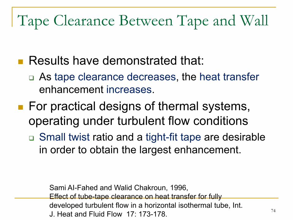
Tape Clearance Between Tape and Wall
Results have demonstrated that:
As tape clearance decreases, the heat transfer
enhancement increases.
For practical designs of thermal systems,
operating under turbulent flow conditions
Small twist ratio and a tight-fit tape are desirable
in order to obtain the largest enhancement.
74
Sami AI-Fahed and Walid Chakroun, 1996,
Effect of tube-tape clearance on heat transfer for fully
developed turbulent flow in a horizontal isothermal tube, Int.
J. Heat and Fluid Flow 17: 173-178.

Dimple Tube with Twisted Tape
For the range of Re between 12000 and 44000,
experimental results reveal that both heat
transfer coefficient and friction factor in the
dimpled tube fitted with the twisted tape, are
higher than those in the dimple tube acting alone
or in a plain tube.
Heat transfer coefficient and friction factor in the
combined devices increase as the pitch ratio (PR)
and twist ratio (y/w) decrease.
75
Chinaruk Thianpong, Petpices Eiamsa-ard, Khwanchit
Wongcharee, Smith Eiamsa-ard, 2009, International
Communications in Heat and Mass Transfer, 36, 698–704
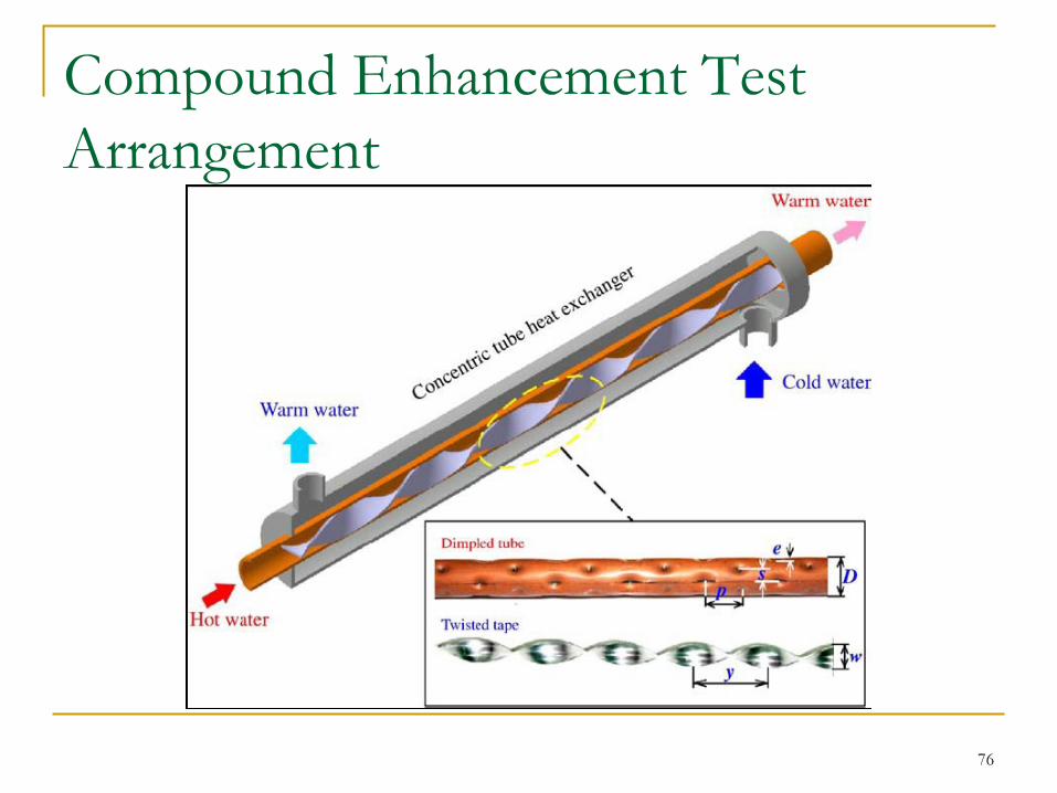
Compound Enhancement Test
Arrangement
76

Compound Enhancements at Low Flows
77
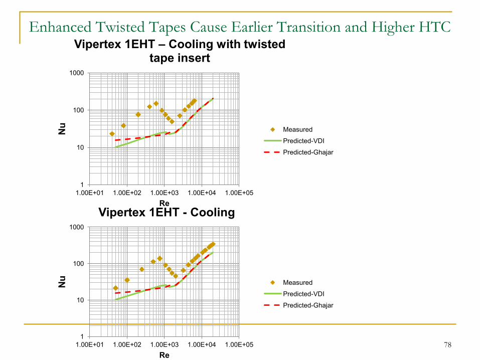
Enhanced Twisted Tapes Cause Earlier Transition and Higher HTC
78 1
10
100
1000
1.00E+01 1.00E+02 1.00E+03 1.00E+04 1.00E+05
Nu
Re
Vipertex 1EHT - Cooling
Measured
Predicted-VDI
Predicted-Ghajar
1
10
100
1000
1.00E+01 1.00E+02 1.00E+03 1.00E+04 1.00E+05
Nu
Re
Vipertex 1EHT – Cooling with twisted tape insert
Measured
Predicted-VDI
Predicted-Ghajar

Need and Justification
There exists a need in industry for high quality, enhanced compound heat transfer tubing that can be used in a variety of industries to meet the needs of heat recovery.
The enhanced products discussed here have been developed for a variety of industries and applications. Waste Heat Recovery
Power plants
Process applications
Energy Conversion
CAPE 2012 Introduction Procedure Results Conclusion 79

Economics is One of the Primary Considerations in
the Development and Evaluation of Process Surfaces
Total Cost Includes:
Initial development costs
Capital costs
Operating costs
Maintenance cost
CAPE 2012 Introduction Procedure Results Conclusion 80

Economic Analysis Parameters
81

Operating Cost Information
82

Economic Analysis
83
1% enhancement
$40045.77
Enhanced - Smooth

Economic Analysis
84
10% enhancement
$594,352
Enhanced - Smooth

Energy Savings with Enhancements
85
10% enhancement
1% enhancement

Summary and Conclusions
An evaluation of the need to enhance heat transfer was performed.
Available Techniques were evaluated.
Criteria Considered for Development
Cost
Material
Performance
Economics
CAPE 2012 Introduction Procedure Results Conclusion 86
Development of Enhanced Heat
Transfer Tubes These compound heat transfer tubes provide heat
transfer rates that are higher than the rates found in
smooth tubes under similar conditions.
This is an important development for the energy
conversion and process industries.
It was demonstrated that more heat transfer and an
earlier transition to high heat transfer can be
accomplished through the use of enhanced twisted
tapes. This was accomplished by: Modeling the surface to evaluate the. enhancement
Lab evaluation of EHT tubes further enhanced with twisted tapes
produced.
CAPE 2012 Introduction Procedure Results Conclusion
87

Summary
Compound Heat Transfer Tubes can be
designed to enhance heat transfer under various
conditions.
Requires different enhanced surfaces and twisted
tapes for different applications.
Tubes have been evaluated and can be designed to
produce more heat transfer than smooth tubes under
fouling conditions. Kukulka et al. (2012)
Kukulka D.J. , Smith R., J. Zaepfel (2012), Development and Evaluation of
Vipertex Enhanced Heat Transfer Tubes for use in Fouling Conditions,
Theoretical Foundations of Chemical Engineering.
.
CAPE 2012 Introduction Procedure Results Conclusion
88

Summary and Conclusions
These enhanced compound heat transfer tubes were tested under some limited operating conditions. Heat Transfer
Enhanced Surface Ratio Values Measured were near 600%
When compared to the results of Thianpong et al. (2009): Magnitude of enhancement is :
Maximum at lower flows;
Thianpong et al. (2009- ) did not evaluate at Re< 12000.
Turbulent Flows Similar magnitude
Surface enhancement configuration Similar
Present study also evaluated enhanced twisted tapes
CAPE 2012 Introduction Procedure Results Conclusion 89

Summary and Conclusions
Future
Additional Testing on Current Designs
Develop Additional Designs
Revised Designs for the Same Applications
New Designs for additional Applications/ Types of Heat
Transfer
Look at two phase flows.
Include Fouling and enhanced twisted tapes
Evaluate a wider range of conditions for the New
Designs.
CAPE 2012 Introduction Procedure Results Conclusion 90

Summary Future studies will examine surface texture
variations in greater detail, coated surfaces and
enhanced surfaces produced from engineered
alloys.
Improvements created through surface texture
enhancements of the heat transfer surface are
clear.
Penalty is the cost to produce the surfaces or twisted tapes.
Total costs over the life of the product will be less than
conventional designs.
Savings produced more than offset the costs.
CAPE 2012 Introduction Procedure Results Conclusion
91

Acknowledgements
Thank you to Rigidized Metals and Vipertex
for their Support in the Development and
Study of Compound Enhanced Heat Transfer
Tubes.
CAPE 2012 Introduction Procedure Results Conclusion 92

Thank You
Questions?
CAPE 2012 Introduction Procedure Results Conclusion 93

94
Related Documents