Ian McEnteggart Composites Testing: Challenges & Solutions JEC Europe - March 2015

Composites Testing: Challenges & Solutions
Jul 18, 2015
Welcome message from author
This document is posted to help you gain knowledge. Please leave a comment to let me know what you think about it! Share it to your friends and learn new things together.
Transcript

Ian McEnteggart
Composites Testing:
Challenges & Solutions
JEC Europe - March 2015

2
Challenges
• Testing Productivity given the large number of
test setups and standards
• Flexible testing equipment
• Easy change over
• Standard test methods
• Achieving and maintaining accurate Alignment
• Need for accurate alignment
• Nadcap alignment criteria
• Measuring Strain
• Standardized testing
• Non-uniform strain fields

3
Composites Require
Various Tests to Characterize
Tension: Fiber-dominant property. Dependant
on the tensile stiffness and strength of the fiber.
Compression: Matrix-dominant property.
Dependant on the stiffness and adhesion
qualities of the resin being able to maintain the
fibers as straight columns and not buckle.
Shear: Matrix-dominant property, transferring
stresses across the composite.
Flexure: Combination of above three: upper
=compression; lower = tension; middle = shear
Also a range of “structural tests” on coupons; e.g. open-hole tension &
compression, bearing load, compression after impact (CAI)
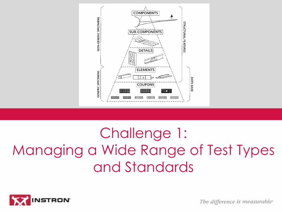
Challenge 1:
Managing a Wide Range of Test Types
and Standards

5
• Unsupported Gauge length (Short)
• ISO 14126
• ASTM D3410 (ITTRI)
• Celanese
• ASTM D6641 (CLC)
• AITM 1-0008 (Hydraulic Grips)
• Supported Gauge Length (Anti-Buckling)
• ISO 14126
• Modified ASTM D695
• ASTM D6484
Compression Testing Configurations
Unsupported Gauge Section
Supported Gauge Section
(Anti-Buckling)
6
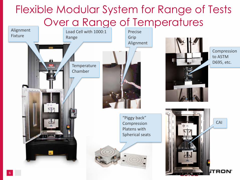
Flexible Modular System for Range of Tests
Over a Range of Temperatures Load Cell with 1000:1 Range
Precise Grip Alignment
Temperature Chamber
CAI
Compression to ASTM D695, etc.
“Piggy back” Compression Platens with Spherical seats
Alignment Fixture
7
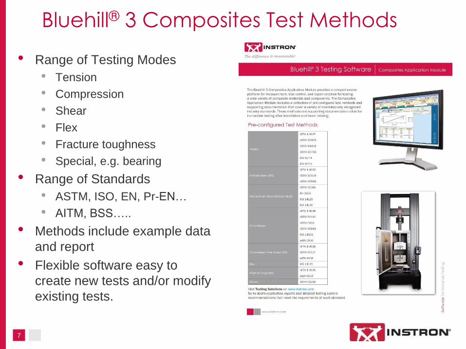
Bluehill® 3 Composites Test Methods
• Range of Testing Modes
• Tension
• Compression
• Shear
• Flex
• Fracture toughness
• Special, e.g. bearing
• Range of Standards
• ASTM, ISO, EN, Pr-EN…
• AITM, BSS…..
• Methods include example data
and report
• Flexible software easy to
create new tests and/or modify
existing tests.

Challenge 2:
Alignment
9
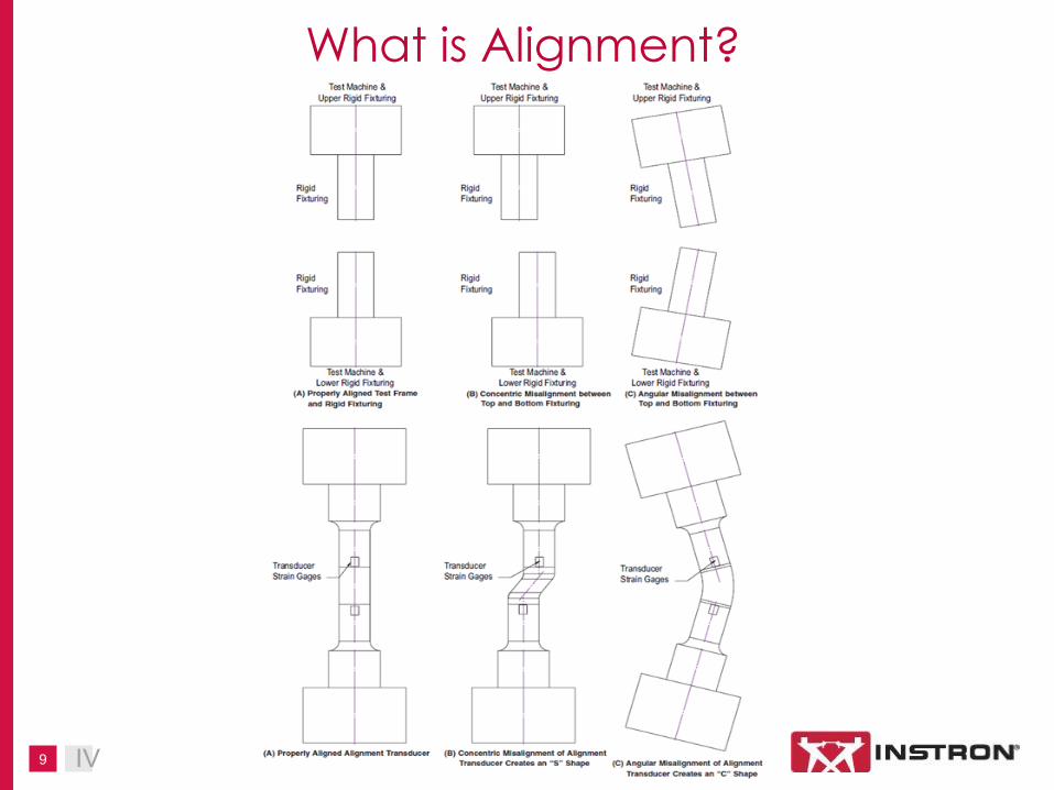
What is Alignment?
IV

10
Why is Alignment so Important for
Composites Testing? Ductile Metal Test
Piece
• Misalignment
introduces uneven
stress distribution
• Metal yields in high
stress region, but
continue to carry load
• Stress redistributes
reducing the effect of
misalignment on test
results
Fiber Composite Test
Piece
• Misalignment
introduces uneven
stress distribution
• Fibers in high-stress
region fail
• Stress in remaining
fibers increases
causing rapid failure
• Misalignment has a
significant effect on
test results
11
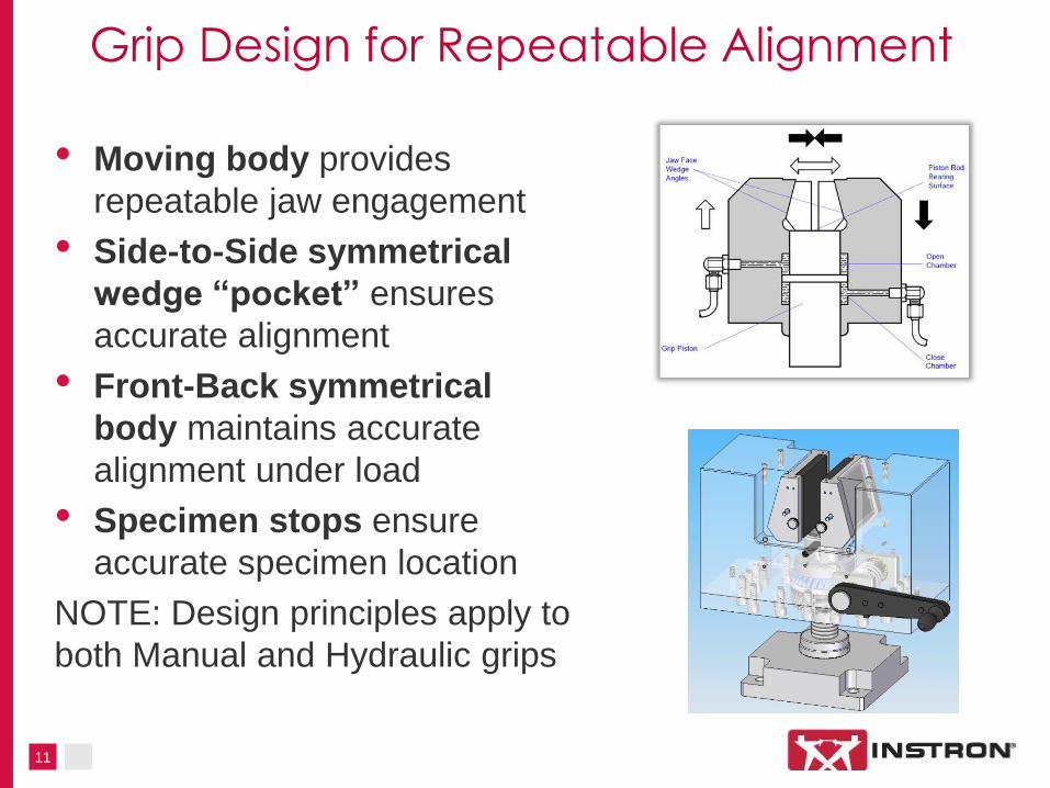
Grip Design for Repeatable Alignment
• Moving body provides
repeatable jaw engagement
• Side-to-Side symmetrical
wedge “pocket” ensures
accurate alignment
• Front-Back symmetrical
body maintains accurate
alignment under load
• Specimen stops ensure
accurate specimen location
NOTE: Design principles apply to
both Manual and Hydraulic grips
12
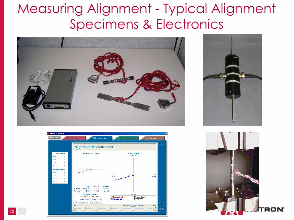
Measuring Alignment - Typical Alignment
Specimens & Electronics
13
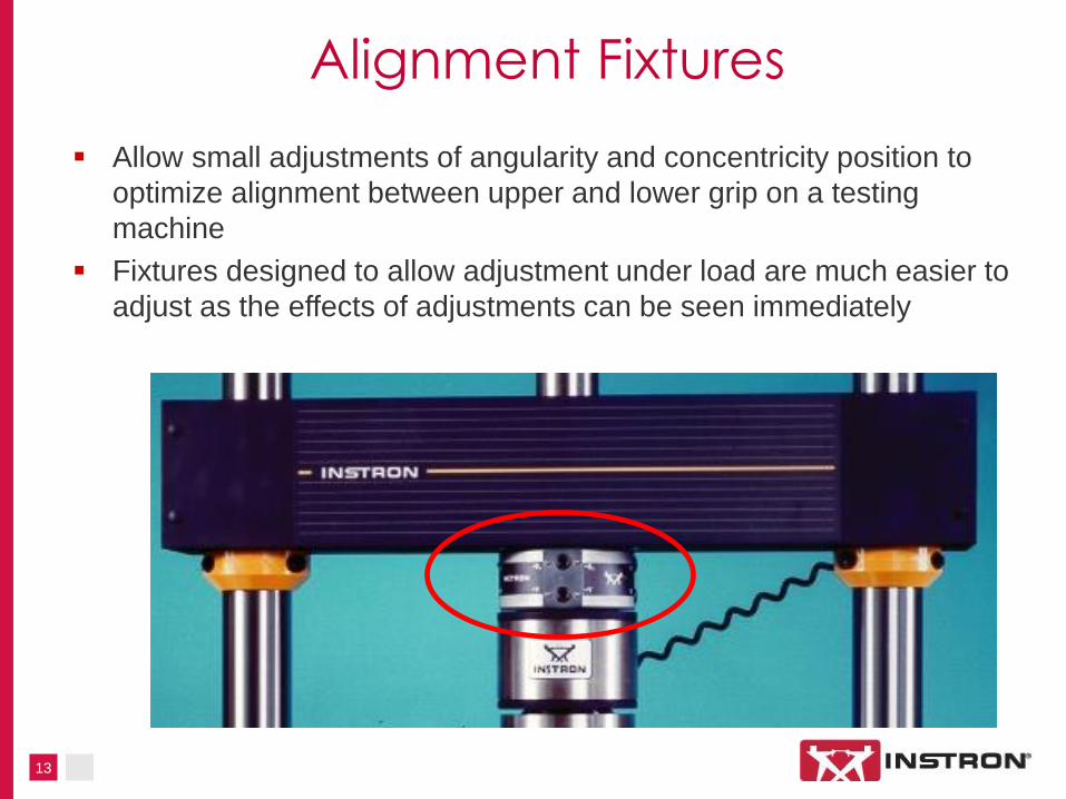
Allow small adjustments of angularity and concentricity position to
optimize alignment between upper and lower grip on a testing
machine
Fixtures designed to allow adjustment under load are much easier to
adjust as the effects of adjustments can be seen immediately
Alignment Fixtures

14
Compression Alignment
• Hydraulic Wedge Grips
• Shear loading
• High lateral stiffness to
maintain alignment under
load
• Spherical Seated
Compression Platens
• Quick and easy mounting on to
fixed grips
• Center of rotation located in the
center of the platen surface
• Lockable
• Meet Nadcap compression
alignment requirements
15
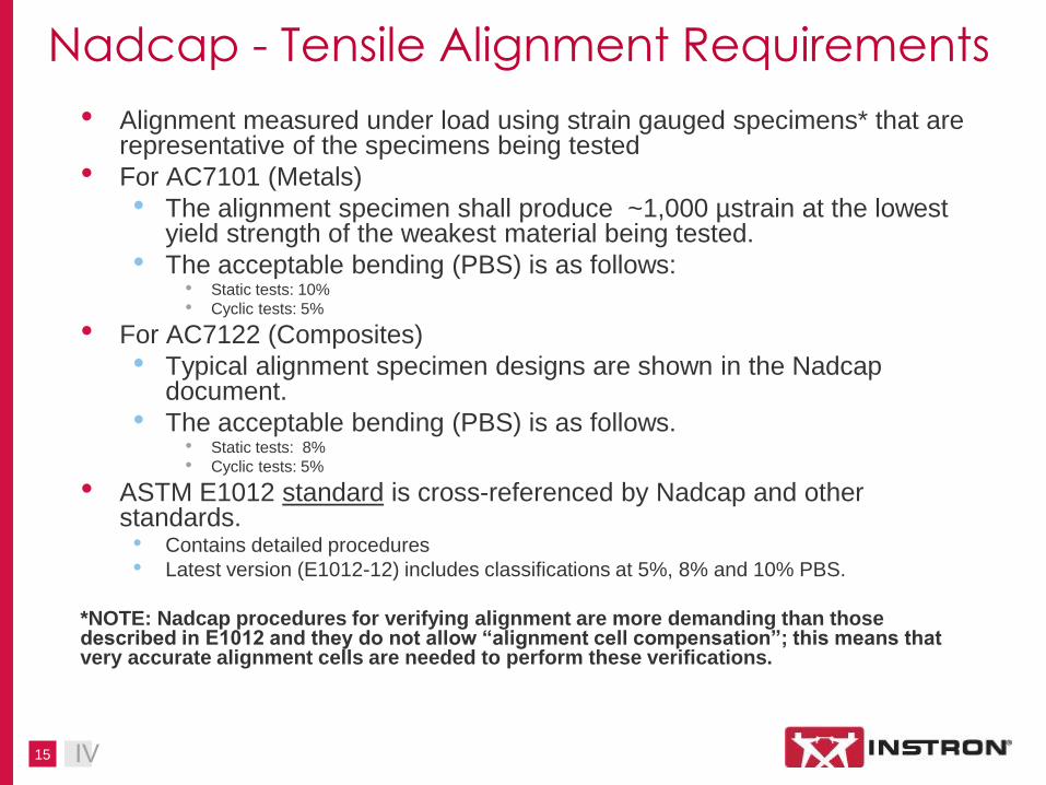
Nadcap - Tensile Alignment Requirements
• Alignment measured under load using strain gauged specimens* that are representative of the specimens being tested
• For AC7101 (Metals)
• The alignment specimen shall produce ~1,000 µstrain at the lowest yield strength of the weakest material being tested.
• The acceptable bending (PBS) is as follows: • Static tests: 10%
• Cyclic tests: 5%
• For AC7122 (Composites)
• Typical alignment specimen designs are shown in the Nadcap document.
• The acceptable bending (PBS) is as follows. • Static tests: 8%
• Cyclic tests: 5%
• ASTM E1012 standard is cross-referenced by Nadcap and other standards. • Contains detailed procedures
• Latest version (E1012-12) includes classifications at 5%, 8% and 10% PBS.
*NOTE: Nadcap procedures for verifying alignment are more demanding than those described in E1012 and they do not allow “alignment cell compensation”; this means that very accurate alignment cells are needed to perform these verifications.
IV

16
… Not Just about Alignment …
• Adherence to Nadcap procedures mean:
• Alignment in accordance with Nadcap
• Alignment specimens are representative of materials being tested
• Calibration frequency is adhered to and calibrated to ISO/ASTM
standards for load cells, extensometers, displacement,
crosshead/speed, etc….
• Preventive maintenance plan is followed
• Training is recorded … operators shall be trained to recognize
proper operation of equipment
• … Services provided by Instron
• Alignment, Gauged Alignment Cells, Calibration, PPM, Training,
Advice
Challenge 3:
Strain Measurement
18
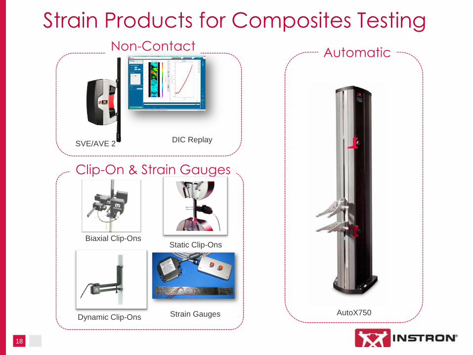
Strain Products for Composites Testing Non-Contact
AutoX750
Automatic
Clip-On & Strain Gauges
Biaxial Clip-Ons Static Clip-Ons
Dynamic Clip-Ons
DIC Replay SVE/AVE 2
Strain Gauges

19
Clip-On Biaxial Extensometer
Main applications in composites
testing
Tensile (including Poisson's ratio)
In Plane Shear (IPS)
Key Features:
Covers a wide range of test
standards
Wide temperature range (-200 to
+200 °C /-328 to +392 °F)
Single-handed attachment
Versions with independent axial
output options (allows
simultaneous monitoring of total
average strain and PBS*)
Compatible with all current
/existing Instron® Systems
*PBS (Percentage Bending Strain)*
𝑃𝐵𝑆 = ∈𝑓−∈𝑏
∈𝑓+∈𝑏 × 100
Where ∈𝑓 and ∈𝑏 are the strains on
either side of the specimen
20
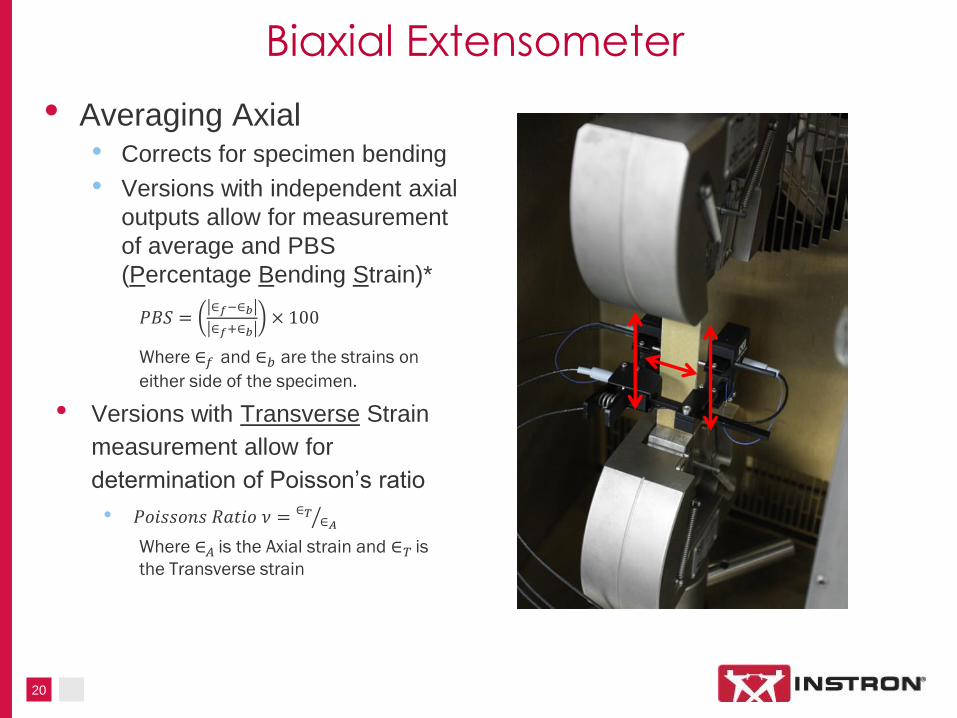
Biaxial Extensometer
• Averaging Axial • Corrects for specimen bending
• Versions with independent axial
outputs allow for measurement
of average and PBS
(Percentage Bending Strain)*
𝑃𝐵𝑆 = ∈𝑓−∈𝑏
∈𝑓+∈𝑏 × 100
Where ∈𝑓 and ∈𝑏 are the strains on
either side of the specimen.
• Versions with Transverse Strain
measurement allow for
determination of Poisson’s ratio
• 𝑃𝑜𝑖𝑠𝑠𝑜𝑛𝑠 𝑅𝑎𝑡𝑖𝑜 𝜈 = ∈𝑇∈𝐴
Where ∈𝐴 is the Axial strain and ∈𝑇 is
the Transverse strain
21
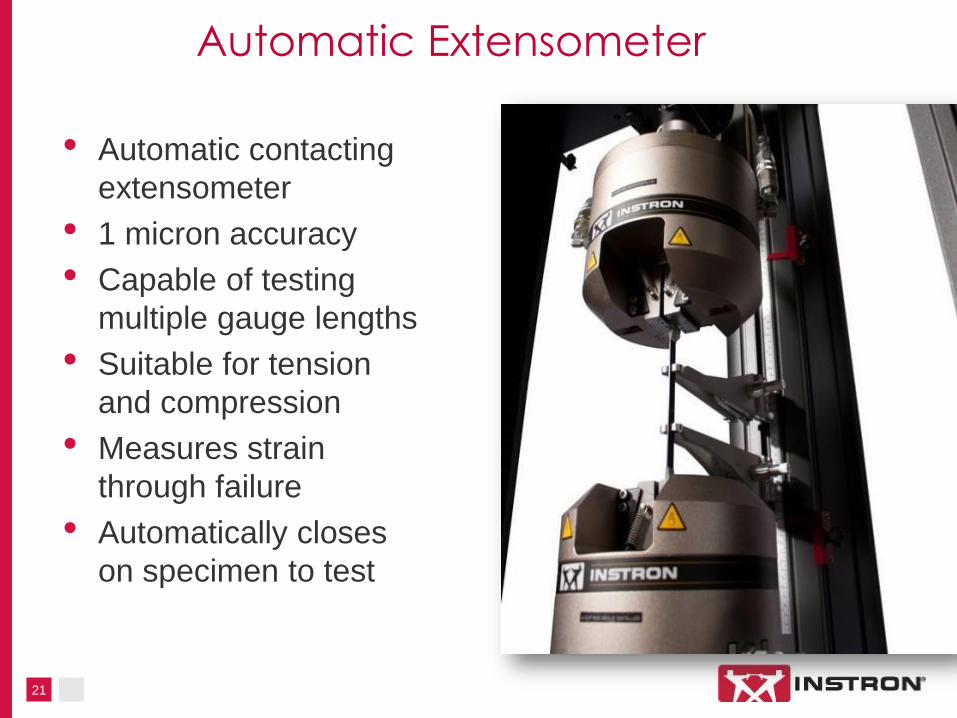
Automatic Extensometer
• Automatic contacting
extensometer
• 1 micron accuracy
• Capable of testing
multiple gauge lengths
• Suitable for tension
and compression
• Measures strain
through failure
• Automatically closes
on specimen to test
22
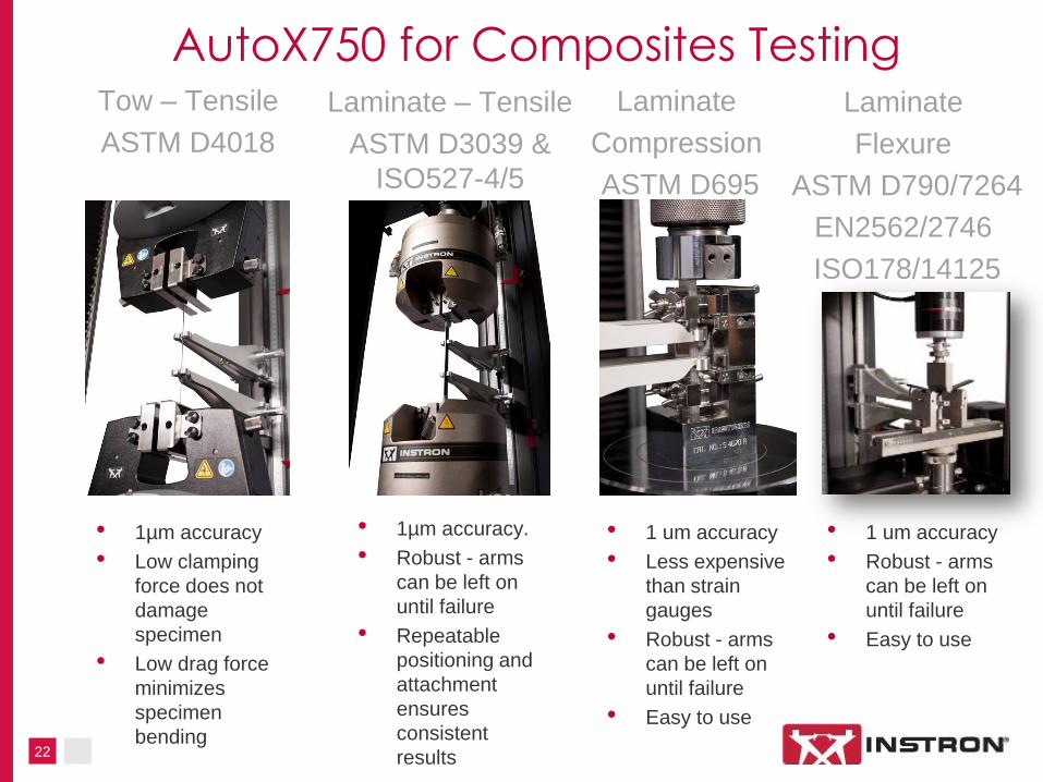
AutoX750 for Composites Testing
• 1µm accuracy.
• Robust - arms
can be left on
until failure
• Repeatable
positioning and
attachment
ensures
consistent
results
• 1µm accuracy
• Low clamping
force does not
damage
specimen
• Low drag force
minimizes
specimen
bending
• 1 um accuracy
• Less expensive
than strain
gauges
• Robust - arms
can be left on
until failure
• Easy to use
Tow – Tensile
ASTM D4018
Laminate – Tensile
ASTM D3039 &
ISO527-4/5
Laminate
Compression
ASTM D695
Laminate
Flexure
ASTM D790/7264
EN2562/2746
ISO178/14125
• 1 um accuracy
• Robust - arms
can be left on
until failure
• Easy to use

Advanced Video Extensometer 2
24
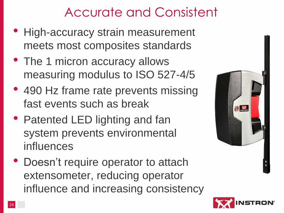
Accurate and Consistent
• High-accuracy strain measurement
meets most composites standards
• The 1 micron accuracy allows
measuring modulus to ISO 527-4/5
• 490 Hz frame rate prevents missing
fast events such as break
• Patented LED lighting and fan
system prevents environmental
influences
• Doesn’t require operator to attach
extensometer, reducing operator
influence and increasing consistency

25
Versatile and Capable
• Can be used to measure both tensile and compressive strain
• Can be used on chambers for cold and hot tensile tests
• Can be used with any testing machine with a +/- 10V input
• Can be used for full field strain measurement using Digital Image Correlation software

26
What is Digital Image Correlation?
Images Displacement Strain
Analysis of image
surface over time Use of cross correlation to
determine displacement
Strain calculated
from displacement
An optical method to measure deformation on an object surface.
27
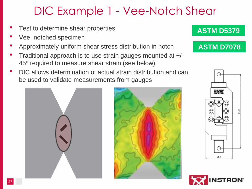
DIC Example 1 - Vee-Notch Shear
• Test to determine shear properties
• Vee–notched specimen
• Approximately uniform shear stress distribution in notch
• Traditional approach is to use strain gauges mounted at +/-
45º required to measure shear strain (see below)
• DIC allows determination of actual strain distribution and can
be used to validate measurements from gauges
ASTM D5379
ASTM D7078

28
DIC Example 2 – Open-Hole Tension
29
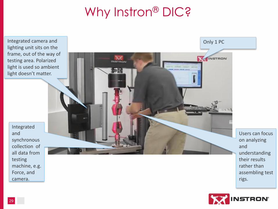
Why Instron® DIC?
Integrated and synchronous collection of all data from testing machine, e.g. Force, and camera.
Only 1 PC Integrated camera and lighting unit sits on the frame, out of the way of testing area. Polarized light is used so ambient light doesn’t matter.
Users can focus on analyzing and understanding their results rather than assembling test rigs.

~Thank you for your attention~
Any Questions?
Related Documents