Compressive characteristics of foam-filled composite egg-box sandwich panels as energy absorbing structures S.H. Yoo a , S.H. Chang a, * , M.P.F. Sutcliffe b a School of Mechanical Engineering, Chung-Ang University, 221, Huksoek-Dong, Dongjak-Gu, Seoul 156-756, Republic of Korea b Department of Engineering, Cambridge University, Trumpington Street, Cambridge CB2 1PZ, UK article info Article history: Received 28 July 2009 Received in revised form 20 October 2009 Accepted 23 November 2009 Keywords: A. Fabrics/textiles A. Foams B. Fracture B. Buckling abstract This paper describes compressive tests on foam-filled composite egg-box panels which were carried out to assess their performance as energy absorbers. Material type, number of plies and stacking angle were varied. Stacking sequences of CFRP [0] nT , CFRP [45] nT (n = 3, 4) and GFRP [0/90] S , [±45] S were used for foam-filled egg-box cores. Fracture modes of representative composite egg-box cores without foam, including crack initiation and propagation, were observed and analysed by multiply-interrupted com- pressive tests using transparent acrylic face plates on both sides of the egg-box core. The concept of pre- mature buckling of the foam-filled egg-box panels is used to explain the small initial stress peak. Finally, the collapse curve of the core was used to estimate energy absorption capacity. It was found that the foam-filled composite egg-box sandwich panels had a good energy absorption capacity with a stable collapse response resembling the ideal energy absorber. Ó 2009 Elsevier Ltd. All rights reserved. 1. Introduction Energy absorbing structures with minimum weight and a com- pact volume for automobile, aeroplane and marine applications are continuously being developed and improved for passenger safety and increased fuel efficiency. Key characteristics in the mechanical performance of energy absorbers are the energy absorption per unit mass or volume and the peak stress during the collapse re- sponse. Since in many applications the role of the absorber is to protect a structure from excessive accelerations during impact, the absorber should not transmit more than a specified force as it collapses. To achieve maximum energy absorption at a given peak stress the panel should exhibit ideally plastic behaviour, undergoing large strains before final failure at the given maximum allowable stress. Polymeric foams and honeycombs have been widely used as cores in sandwich structures in combination with high stiffness face sheets to fulfil this requirement. Such panels can resist high loads while they undergo large strains before completely collaps- ing [1]. Various materials and geometric configurations have been investigated to find more effective lightweight energy absorbing structures. Cartie and Fleck [2] investigated the compressive strength of foam-cored sandwich plates with z-pin reinforcements. The com- pressive strength and energy absorption capacity of the sandwich plates, considering in this case the foam as performing the energy absorbing function, was estimated using an experimental study and buckling analysis. Harte et al. [3] investigated the energy absorption of foam-filled circular composite tubes made of braided glass/epoxy composites and ascertained the effects of tube wall strength and foam density. Hamada et al. [4] carried out compres- sive tests of braided composite rods with a flexible interphase to increase energy absorption of the structure. They found that com- posite rods with a flexible interphase had a 30% higher specific en- ergy absorption capacity than the ordinary braided composite rod. Turning to the role of the absorber geometry, various geometri- cal shapes have been considered for energy absorbing structures such as tubes, frusta, multicorner columns and struts [5]. The appropriate shape for energy absorbing structures will depend on the application field, the type of loading and the constraints. Lam et al. [6] investigated the energy absorption behaviour of a flat- topped grid-domed cellular structure made of different textile composites and they found experimentally the effects of fibre type, fibre volume fraction and fibre architecture on energy absorption. Yu et al. [7] studied the compressive characteristics and energy absorption of grid-domed composites made of knitted fabrics and they compared the energy absorption of these specimens with sev- eral conventional foams. Soutis and Poubady [8] and Velecela et al. [9] examined and analysed energy absorption capacities of flat composite specimens under ‘edgewise compression’ considering the geometry of collapse trigger mechanism and successfully found the most effective condition for inducing progressive failure of specimens. Among many geometric shapes conical frusta have 1359-835X/$ - see front matter Ó 2009 Elsevier Ltd. All rights reserved. doi:10.1016/j.compositesa.2009.11.010 * Corresponding author. Tel.: +82 2 820 5354; fax: +82 2 814 9476. E-mail address: [email protected] (S.H. Chang). Composites: Part A 41 (2010) 427–434 Contents lists available at ScienceDirect Composites: Part A journal homepage: www.elsevier.com/locate/compositesa

Welcome message from author
This document is posted to help you gain knowledge. Please leave a comment to let me know what you think about it! Share it to your friends and learn new things together.
Transcript
Composites: Part A 41 (2010) 427–434
Contents lists available at ScienceDirect
Composites: Part A
journal homepage: www.elsevier .com/locate /composi tesa
Compressive characteristics of foam-filled composite egg-box sandwich panelsas energy absorbing structures
S.H. Yoo a, S.H. Chang a,*, M.P.F. Sutcliffe b
a School of Mechanical Engineering, Chung-Ang University, 221, Huksoek-Dong, Dongjak-Gu, Seoul 156-756, Republic of Koreab Department of Engineering, Cambridge University, Trumpington Street, Cambridge CB2 1PZ, UK
a r t i c l e i n f o
Article history:Received 28 July 2009Received in revised form 20 October 2009Accepted 23 November 2009
Keywords:A. Fabrics/textilesA. FoamsB. FractureB. Buckling
1359-835X/$ - see front matter � 2009 Elsevier Ltd. Adoi:10.1016/j.compositesa.2009.11.010
* Corresponding author. Tel.: +82 2 820 5354; fax:E-mail address: [email protected] (S.H. Chang).
a b s t r a c t
This paper describes compressive tests on foam-filled composite egg-box panels which were carried outto assess their performance as energy absorbers. Material type, number of plies and stacking angle werevaried. Stacking sequences of CFRP [0]nT, CFRP [45]nT (n = 3, 4) and GFRP [0/90]S, [±45]S were used forfoam-filled egg-box cores. Fracture modes of representative composite egg-box cores without foam,including crack initiation and propagation, were observed and analysed by multiply-interrupted com-pressive tests using transparent acrylic face plates on both sides of the egg-box core. The concept of pre-mature buckling of the foam-filled egg-box panels is used to explain the small initial stress peak. Finally,the collapse curve of the core was used to estimate energy absorption capacity. It was found that thefoam-filled composite egg-box sandwich panels had a good energy absorption capacity with a stablecollapse response resembling the ideal energy absorber.
� 2009 Elsevier Ltd. All rights reserved.
1. Introduction
Energy absorbing structures with minimum weight and a com-pact volume for automobile, aeroplane and marine applications arecontinuously being developed and improved for passenger safetyand increased fuel efficiency. Key characteristics in the mechanicalperformance of energy absorbers are the energy absorption perunit mass or volume and the peak stress during the collapse re-sponse. Since in many applications the role of the absorber is toprotect a structure from excessive accelerations during impact,the absorber should not transmit more than a specified force asit collapses. To achieve maximum energy absorption at a givenpeak stress the panel should exhibit ideally plastic behaviour,undergoing large strains before final failure at the given maximumallowable stress.
Polymeric foams and honeycombs have been widely used ascores in sandwich structures in combination with high stiffnessface sheets to fulfil this requirement. Such panels can resist highloads while they undergo large strains before completely collaps-ing [1]. Various materials and geometric configurations have beeninvestigated to find more effective lightweight energy absorbingstructures.
Cartie and Fleck [2] investigated the compressive strength offoam-cored sandwich plates with z-pin reinforcements. The com-pressive strength and energy absorption capacity of the sandwich
ll rights reserved.
+82 2 814 9476.
plates, considering in this case the foam as performing the energyabsorbing function, was estimated using an experimental studyand buckling analysis. Harte et al. [3] investigated the energyabsorption of foam-filled circular composite tubes made of braidedglass/epoxy composites and ascertained the effects of tube wallstrength and foam density. Hamada et al. [4] carried out compres-sive tests of braided composite rods with a flexible interphase toincrease energy absorption of the structure. They found that com-posite rods with a flexible interphase had a 30% higher specific en-ergy absorption capacity than the ordinary braided composite rod.
Turning to the role of the absorber geometry, various geometri-cal shapes have been considered for energy absorbing structuressuch as tubes, frusta, multicorner columns and struts [5]. Theappropriate shape for energy absorbing structures will depend onthe application field, the type of loading and the constraints. Lamet al. [6] investigated the energy absorption behaviour of a flat-topped grid-domed cellular structure made of different textilecomposites and they found experimentally the effects of fibre type,fibre volume fraction and fibre architecture on energy absorption.Yu et al. [7] studied the compressive characteristics and energyabsorption of grid-domed composites made of knitted fabrics andthey compared the energy absorption of these specimens with sev-eral conventional foams. Soutis and Poubady [8] and Velecela et al.[9] examined and analysed energy absorption capacities of flatcomposite specimens under ‘edgewise compression’ consideringthe geometry of collapse trigger mechanism and successfully foundthe most effective condition for inducing progressive failure ofspecimens. Among many geometric shapes conical frusta have

428 S.H. Yoo et al. / Composites: Part A 41 (2010) 427–434
been widely investigated because they have an axisymmetricalshape, which is easy to apply to many structures and they alsohave an effective collapsing mechanism under inversion load[10]. Being effectively a square array of conical frusta, the egg-box shape has also extensively been investigated for potentialuse not only for energy absorbing structures but also for soundand vibration absorption for an automobile chassis [11]. Deshpan-de and Fleck [12] investigated the collapse mechanism of egg-boxshaped structures, constructing collapse maps identifying regionsof elastic buckling, material tearing and travelling plastic hinges,to provide useful tools to select an appropriate egg-box design. Zu-pan et al. [13] carried out compressive tests and finite elementanalysis on aluminium egg-box panels compressed with three dif-ferent boundary conditions; unconstrained, constrained andbonded. They found significant differences depending on theseboundary conditions. Energy absorption per unit mass and unitvolume were measured as a function of a relative density andboundary conditions. Chung et al. [14] investigated the compres-sive characteristics of composite egg-box cores where the corewas not bonded to face sheets, giving an unconstrained boundarycondition. They used specimens with two types of composite andvarious stacking sequences to find the effect of material and plynumber on energy absorption. From this experimental study theyshowed that composite egg-box cores are superior to aluminiumegg-box core as energy absorbers in weight-critical applications.Nevertheless the collapse response of these cores departed fromthe ideal response. Preliminary tests of bonded egg-box coresshowed a high initial peak stress before undergoing a large strainduring the subsequent collapse response. Given the encouragingresults of this preliminary work, this paper describes a follow upstudy, describing a similar series of tests, but with bonded facesheets, giving similar conditions to those studied by Zupan et al.[13], and with the inclusion of foam in the core. Preliminary re-search [15] established a testing methodology and reported preli-minary results for the general collapsing behaviour of bondedegg-box panels. The current paper aims to evaluate the possibleuse of foam-filled composite egg-box panels as a thermal insula-tion component for membrane type liquefied natural gas (LNG)ships, which needs to have not only thermal insulation capacitybut also (hydrostatic and hydrodynamic) load carrying capacity.In order to do this, the collapse mechanism of foam-filled compos-ite egg-box panels is identified and compared with that of the un-filled composite panels. This represents a more in-depthexperimental study of foam-filled composite egg-box panels thanthe preliminary work of Yoo and Chang [15]. The reason of selec-tion of this structure was that the egg-box geometry can be easilystamped in a single operation, reducing the production costs [11]while maintaining an excellent energy absorbing capacity [13].Apart from the usage of the panel in the thermal insulation compo-nent, foam-filled composite egg-box structures have potentialapplications in various protective packaging and crashworthinessstructures for automobiles, ships and aeroplanes.
2. Specimen details and fabrication
For the fabrication of the composite egg-box cores two differentfabric prepregs were used; a carbon/epoxy plain weave fabric pre-preg (EL = ET = 54 GPa, XL = XT = 591 MPa, q = 1480 kg/m3) and aglass/epoxy 4-harness satin weave fabric prepreg (EL = 38 GPa,ET = 16 GPa, XL = 692 MPa, XT = 250 MPa, q = 1830 kg/m3), referredto simply as ‘CFRP’ and ‘GFRP’ in this paper. The moduli and strengthparameters (details in Refs. [14,15]) were measured following ASTMstandards [16,17].
The shape and important geometric terms used to describe thecomposite egg-box core are shown in Fig. 1a and b. The side-wall
connects truncated tops and bottoms and the saddle is located inbetween truncated tops or truncated bottoms. The overall dimen-sions (length �width � height) of the core are 180 mm � 125mm � 20 mm, and it contains 12 truncated tops and six truncatedbottoms. In order to fabricate the composite egg-box cores, siliconerubber moulds were first made using an aluminium egg-box tem-plate which had been used in Refs. [13–15], then prepregs weredraped onto the moulds, vacuum bagged and cured in an autoclaveusing the recommended curing cycle; that is, the curing tempera-ture rises to 80 �C in 30 min and after dwelling for 30 min it risesagain to 125 �C for 15 min and then dwells again for three and halfhours. To construct a sandwich panel, flat composite face sheetsmade of GFRP ([0/90]S) were attached to the top and bottom sur-faces of the egg-boxes using adhesive bonding at the truncatedtops and bottoms of the egg-box core. These face sheets do notaffect the collapse behaviour of the egg-box cores significantlybut they do provide a bonding boundary condition. In addition tothe standard sandwich panels, a new type of composite egg-boxsandwich panel was prepared containing polyurethane (PU) foams(for low density qf = 22 kg/m3 and for high density 53 kg/m3)which completely filled the cavities of the composite egg-box core(see Fig. 1c). This foam (LC-foam, Henkel, Korea) containing LPGand DME (dimethyl ether:CH3OCH3) gases for spraying was of aself-expanding type which could easily be sprayed into the cores,ensuring that cost and manufacturing difficulties were not greatlyincreased by this additional step in the process. During the expan-sion process dummy face sheets were placed on the core to ensurea good fit between the foam and the working face sheets and to al-low an appropriate foam density during curing. The finished coreswere then adhesively bonded to construct the sandwich panel.Epoxy adhesive was applied only to the truncated tops and bot-toms and cured at room temperature for 24 h. The fabricated com-posite egg-box cores include the stacking sequences used of [0]nT
(n = 1–4) and [45]nT (n = 1–4) for CFRP and [0]nT (n = 1–4) and[45]nT (n = 1–4) and [0/90]S, [±45]S for GFRP to investigate the effectof changing the warp and weft directions with these unbalancedlaminates. Because the egg-box geometry was quite complex, rep-resentative stacking angles (0, 90, 45) with the simplest lay-up forthe specimens have been used to find out the effect of stacking se-quence on collapse behaviour and energy absorption capacity.
3. Compressive test methodology
Compressive tests were carried out in a universal testing ma-chine (MTS810, USA). The plate was loaded in between thick alu-minium compression platens which contacted the face sheets ofthe plate and slightly extended beyond the edge of the specimen,so that the plates were compressed in the through-thickness direc-tion (lateral compression, see Figs. 1d and 3c). The compressionspeed was 2 mm/min and the collapse curves were plotted interms of nominal stress (compressive load divided by projectedarea) and nominal strain (out-of-plane displacement divided bythe original height of the specimen). All the compressive tests foreach type of specimen were carried out at least four times and re-sults averaged.
4. Results
4.1. Collapse response
4.1.1. Sandwich panels without foamFig. 2 shows representative collapse curves of composite
egg-box cores for the CFRP and GFRP cores without the foam. Incontrast to the earlier results for egg-box cores which were uncon-strained by the bonded face sheets [14], the new cores showed a

Truncated Top
Truncated Bottom
Side-wallSide-wall
Saddle
Side-wallSide-wall
xy
z
A
A
B
B
125mm
180mm
(a)
Side-wall
Truncated Top
Side-wall
35mm
15mm
Truncated Bottom Truncated Bottom
35mm
20mm
A A
15mm
Truncated Top
Saddle
49.5mmTruncated Top
SaddleSaddle10mm
49.5mm BB
(b)
(c)
Load
Load
(d) Fig. 1. The shape of composite egg-box core and major terminologies: (a) overall shape and dimensions, (b) principal contour geometries, (c) foam-filled egg-box panel foruse as the core of sandwich structure, and (d) loading direction.
S.H. Yoo et al. / Composites: Part A 41 (2010) 427–434 429

Nominal strain[mm/mm]0.0 0.1 0.2 0.3 0.4 0.5 0.6 0.7 0.8 0.9
Nom
inal
str
ess[
MPa
]
0.0
0.2
0.4
0.6
0.8
1.0
1.2
1.4
1.6
1.8
2.0
Unconstrained CFRP[0] 4T
Unconstrained CFRP[45] 4T
Bonded CFRP[0] 4T
Bonded CFRP[45] 4T
(a)
Nominal strain[mm/mm]0.0 0.1 0.2 0.3 0.4 0.5 0.6 0.7 0.8 0.9
Nom
inal
str
ess[
MPa
]
0.0
0.2
0.4
0.6
0.8
1.0
1.2
1.4
1.6
1.8
2.0
Unconstrained GFRP[0]4T
Unconstrained GFRP[45]4T
Bonded GFRP[0]4T
Bonded GFRP[45]4T
Bonded GFRP[0/90]S
Bonded GFRP[ ]S45±
(b)
Fig. 2. Representative collapse responses of bonded composite egg-box cores: (a) CFRP and (b) GFRP.
430 S.H. Yoo et al. / Composites: Part A 41 (2010) 427–434
stress peak at a relatively low strain (e < 0.1). This phenomenonwas caused by the bonding boundary condition preventing theegg-box core from sliding horizontally during compression. Thisincreases the in-plane compressive forces in the material. Fig. 2aand b for the CFRP and GFRP shows that there are no significantdifferences in stress–strain behaviour during the collapse responsebetween the two different stacking sequences ([0]nT and [45]nT) forthe CFRP. However for the GFRP cores the stacking sequence of[45]nT has a slightly higher stress level, which may be caused bythe differences in material properties arising as warp and wefttows travel along different paths over the egg-box geometry. Thiscollapse response for the bonded cores contrasts with resultsshown in Fig. 2 for the unconstrained egg-box cores, where it isseen that, after an initial rise, the collapse response has a more-or less plateau region (with a slight increase in collapse stress inthis region) until final densification at a large strain, when thestress rises abruptly.
The woven GFRP satin weave material contains different proper-ties in the warp and weft directions as mentioned in Section 2. Toinvestigate the effect of changing the warp and weft directions, GFRPegg-box cores were prepared simply-stacked ([0]nT, [45]nT) andsymmetrically-stacked ([0/90]S, [±45]S). Fig. 2b compares the re-sponse for these stacking sequences. The simply-stacked specimenshave a plateau regime (0.15 < e < 0.6) between the stress peak anddensification, due to splitting behaviour along the longitudinal tows.The symmetrically-stacked specimens had almost the same collapseresponse as the CFRP specimens, with no splitting. This may reflectthe fact that, for both the CFRP plain weave and the symmetrically-stacked satin weave GFRP specimens, there is no difference betweenproperties in the longitudinal and transverse directions.
Only the collapse curves for the four-ply egg-box core are in-cluded in Fig. 2. The three-ply egg-box cores had a similar behav-iour to the four-ply cores, while the one and two-ply egg-boxcores showed very low stress levels in the plateau regime, withsimilar results for the different lay-ups used. In comparison withother research results [8,9] the low level of nominal stress wascaused by the large projected area in the calculation of the nominalstress (taking not the force per unit material cross-section but thelateral compressive force per unit face sheet area), which again re-sulted in low energy absorption per unit mass.
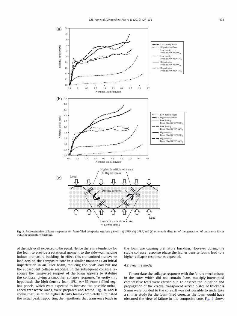
4.1.2. Collapse response for foam-filled panelsFig. 3a and b shows the collapse responses of the CFRP and GFRP
foam-filled egg-box sandwich panels, respectively. These resultscan be compared with corresponding Fig. 2a and b for the unfilledpanels. The low density foam-filled panels show a similar stress le-vel of collapse response as the unfilled panels but with much morestable collapse in the plateau regime. Remarkably they do notshow the high initial stress peak as the unfilled cores. In otherwords they better represent an ideal energy absorber which max-imises absorbed energy at a given stress level. One hypothesis forthis loss of the initial peak is that the transverse stresses transmit-ted through the core from the face sheet cause premature bucklingof the side-walls of the composite core. The composite egg-boxcore intrinsically has a shape which will act as an imperfectionto initiate buckling. Moreover loading from the foam on either sideof the side-walls is expected to be asymmetric, as illustrated inFig. 3c, with greater densification and hence greater stress on theside of the wall closer to a corresponding face sheet. Only in thecentre of the panel are the stresses from the foam on either side
Nominal strain[mm/mm]
Nom
inal
str
ess[
MPa
]
0.0
0.2
0.4
0.6
0.8
1.0
1.2
1.4
1.6
1.8
2.0
Low density FoamHigh density FoamLow densityFoam filled CFRP[0]4T
Low densityFoam filled CFRP[45]4T
High density Foam filled CFRP[0]4T
High densityFoam filled CFRP[45]4T
(a)
Nominal strain[mm/mm]
0.0 0.1 0.2 0.3 0.4 0.5 0.6 0.7 0.8 0.9
0.0 0.1 0.2 0.3 0.4 0.5 0.6 0.7 0.8 0.9
Nom
inal
str
ess[
MPa
]
0.0
0.2
0.4
0.6
0.8
1.0
1.2
1.4
1.6
1.8
2.0
Low density FoamHigh density FoamLow density Foam filled GFRP[0/90]S
Low density Foam filled GFRP[ ]S
High density Foam filled GFRP[0/90]S
High densityFoam filled GFRP[ ]S
45±
45±
(b)
Higher densification strainHigher stress
Lower densification strainLower stress
Load
Load
(c)
Fig. 3. Representative collapse responses for foam-filled composite egg-box panels: (a) CFRP, (b) GFRP, and (c) schematic diagram of the generation of unbalance forcesinducing premature buckling.
S.H. Yoo et al. / Composites: Part A 41 (2010) 427–434 431
of the side-wall expected to be equal. Hence there is a tendency forthe foam to provide a rotational moment to the side-wall helpinginduce premature buckling. In effect this transmitted transverseload acts on the composite core in a similar manner as an initialimperfection in an Euler beam, reducing the peak load but notthe subsequent collapse response. In the subsequent collapse re-sponse the transverse support of the foam appears to stabilisethe collapse, giving a smoother collapse response. To verify thishypothesis the high density foam (PU, qf = 53 kg/m3) filled egg-box panels, which were expected to increase the possible unbal-anced transverse loads, were prepared and tested. Fig. 3a and bshows that use of the higher density foams completely eliminatedthe initial peak, supporting the hypothesis that transverse loads in
the foam are causing premature buckling. However during thestable collapse response phase the higher density foams lead to ahigher collapse response as expected.
4.2. Fracture modes
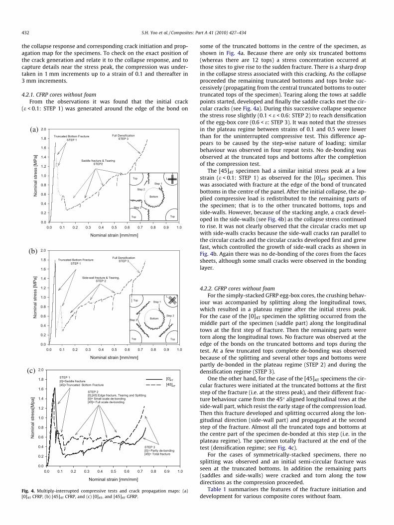
To correlate the collapse response with the failure mechanismsin the cores which did not contain foam, multiply-interruptedcompressive tests were carried out. To observe the initiation andpropagation of the cracks, transparent acrylic plates of thickness5 mm were bonded to the cores. It was not possible to undertakea similar study for the foam-filled cores, as the foam would haveobscured the view of failure in the composite core. Fig. 4 shows
432 S.H. Yoo et al. / Composites: Part A 41 (2010) 427–434
the collapse response and corresponding crack initiation and prop-agation map for the specimens. To check on the exact position ofthe crack generation and relate it to the collapse response, and tocapture details near the stress peak, the compression was under-taken in 1 mm increments up to a strain of 0.1 and thereafter in3 mm increments.
4.2.1. CFRP cores without foamFrom the observations it was found that the initial crack
(e < 0.1: STEP 1) was generated around the edge of the bond on
Nominal strain [mm/mm]
0.0 0.1 0.2 0.3 0.4 0.5 0.6 0.7 0.8 0.9 1.0
Nom
inal
stre
ss [M
Pa]
0.0
0.2
0.4
0.6
0.8
1.0
1.2
1.4
1.6
1.8
2.0
Truncated Bottom Fracture STEP 1
Saddle fracture & TearingSTEP2
Full Densification STEP 3
(a)
Nominal strain [mm/mm]
0.0 0.1 0.2 0.3 0.4 0.5 0.6 0.7 0.8 0.9 1.0
Nom
inal
stre
ss [M
Pa]
0.0
0.2
0.4
0.6
0.8
1.0
1.2
1.4
1.6
1.8
2.0
Truncated Bottom FractureSTEP 1
Side-wall fracture & Tearing, STEP 2
Full Densification STEP 3
(b)
Nominal strain [mm/mm]
0.0 0.1 0.2 0.3 0.4 0.5 0.6 0.7 0.8 0.9 1.0
Nom
inal
stre
ss[M
pa]
0.0
0.2
0.4
0.6
0.8
1.0
1.2
1.4
1.6
1.8
2.0
[0]4T
[45]4T
STEP 1[0]=Saddle fracture[45]=Truncated Bottom Fracture
STEP 2[0],[45] Edge fracture, Tearing and Splitting[0]= Small scale de-bonding[45]= Full scale de-bonding
STEP 3[0]= Partly de-bonding[45]= Total fracture
(c)
Top Top
Top
TopTop
Top
Step 2
Step 1
Step 2
Step 2
Step 1
Step 2
Bottom
Bottom
L
T
L T
Fig. 4. Multiply-interrupted compressive tests and crack propagation maps: (a)[0]4T CFRP, (b) [45]4T CFRP, and (c) [0]4T, and [45]4T GFRP.
some of the truncated bottoms in the centre of the specimen, asshown in Fig. 4a. Because there are only six truncated bottoms(whereas there are 12 tops) a stress concentration occurred atthose sites to give rise to the sudden fracture. There is a sharp dropin the collapse stress associated with this cracking. As the collapseproceeded the remaining truncated bottoms and tops broke suc-cessively (propagating from the central truncated bottoms to outertruncated tops of the specimen). Tearing along the tows at saddlepoints started, developed and finally the saddle cracks met the cir-cular cracks (see Fig. 4a). During this successive collapse sequencethe stress rose slightly (0.1 < e < 0.6: STEP 2) to reach densificationof the egg-box core (0.6 < e: STEP 3). It was noted that the stressesin the plateau regime between strains of 0.1 and 0.5 were lowerthan for the uninterrupted compressive test. This difference ap-pears to be caused by the step-wise nature of loading; similarbehaviour was observed in four repeat tests. No de-bonding wasobserved at the truncated tops and bottoms after the completionof the compression test.
The [45]4T specimen had a similar initial stress peak at a lowstrain (e < 0.1: STEP 1) as observed for the [0]4T specimen. Thiswas associated with fracture at the edge of the bond of truncatedbottoms in the centre of the panel. After the initial collapse, the ap-plied compressive load is redistributed to the remaining parts ofthe specimen; that is to the other truncated bottoms, tops andside-walls. However, because of the stacking angle, a crack devel-oped in the side-walls (see Fig. 4b) as the collapse stress continuedto rise. It was not clearly observed that the circular cracks met upwith side-walls cracks because the side-wall cracks ran parallel tothe circular cracks and the circular cracks developed first and grewfast, which controlled the growth of side-wall cracks as shown inFig. 4b. Again there was no de-bonding of the cores from the facessheets, although some small cracks were observed in the bondinglayer.
4.2.2. GFRP cores without foamFor the simply-stacked GFRP egg-box cores, the crushing behav-
iour was accompanied by splitting along the longitudinal tows,which resulted in a plateau regime after the initial stress peak.For the case of the [0]4T specimen the splitting occurred from themiddle part of the specimen (saddle part) along the longitudinaltows at the first step of fracture. Then the remaining parts weretorn along the longitudinal tows. No fracture was observed at theedge of the bonds on the truncated bottoms and tops during thetest. At a few truncated tops complete de-bonding was observedbecause of the splitting and several other tops and bottoms werepartly de-bonded in the plateau regime (STEP 2) and during thedensification regime (STEP 3).
One the other hand, for the case of the [45]4T specimens the cir-cular fractures were initiated at the truncated bottoms at the firststep of the fracture (i.e. at the stress peak), and their different frac-ture behaviour came from the 45� aligned longitudinal tows at theside-wall part, which resist the early stage of the compression load.Then this fracture developed and splitting occurred along the lon-gitudinal direction (side-wall part) and propagated at the secondstep of the fracture. Almost all the truncated tops and bottoms atthe centre part of the specimen de-bonded at this step (i.e. in theplateau regime). The specimen totally fractured at the end of thetest (densification regime; see Fig. 4c).
For the cases of symmetrically-stacked specimens, there nosplitting was observed and an initial semi-circular fracture wasseen at the truncated bottoms. In addition the remaining parts(saddles and side-walls) were cracked and torn along the towdirections as the compression proceeded.
Table 1 summarises the features of the fracture initiation anddevelopment for various composite cores without foam.

Table 1Summary of the important fracture configurations of composite cores.
Material STEPS
1 2 3
CFRP[0]4T � Truncated bottom fracture at the
centre of the core� Crack propagation (centre to outerparts of core)
� Some combined circular cracks and saddlecracks
� Initial stress peak � Tearing at saddle � No de-bonding� Stress rise � Large scale fracture around truncated tops
and bottoms
[45]4T � Truncated bottom fracture � Side-wall fracture initiation at thecentre of the core
� Some cracks at the bonding layer
� Initial stress peak � Stress rise � Large scale fracture around truncated topsand bottomsGFRP
[0]4T � Splitting at the saddle � Edge fracture (Tearing) � Partly de-bonding due to splitting� Initial stress peak � Partly de-bonding� No fracture at truncated bottoms � Large scale tearing and splitting � Large scale fracture
[45]4T � Truncated bottom fracture � Splitting at side-walls � Full scale fracture� Initial stress peak � Full scale de-bonding � Complete de-bonding
� Edge tearing
[0/90]S � Truncated bottom fracture � Tearing at saddles � Large scale tearing� Initial stress peak � Truncated top fracture � Crack combining between saddles and
truncated tops and bottoms� Full scale de-bonding
[±45]S � Truncated bottom fracture � Tearing at side-walls � Large scale tearing� Initial stress peak � Truncated top fracture � Crack combining between side-walls and
truncated tops and bottoms� Full scale de-bonding
S.H. Yoo et al. / Composites: Part A 41 (2010) 427–434 433
5. Energy absorption capacity
The energy absorption per unit volume (Ev) of the panels wascalculated by integrating the stress–strain curves. To make a com-parison with the energy absorption of aluminium egg-box panels[13] the integration was carried out up to a nominal strain of 0.6.Energy absorption per unit mass (Em) was also calculated by usingthe following formulae:
Em ¼ Ev=qq ðfor composite egg-box coresÞ ð1Þ
Em ¼ Ev=qeq ðfor foam-filled egg-box coresÞ ð2Þ
qeq ¼ qcmc þ qf mf ð3Þ
where q, qeq and q are the mass density of the solid material forcomposite egg-box cores, the equivalent density for foam-filledegg-box cores and the relative density, which is defined as the massof the core divided by the mass of a solid rectangular block of thesame material enclosing the core. Here qc and qf are the densitiesof the composite and foam, respectively, and mc and mf are the vol-ume fractions of the composite and foam, respectively. The massof the face sheets was omitted from the calculation because theyhardly affect the energy absorption during the compression.
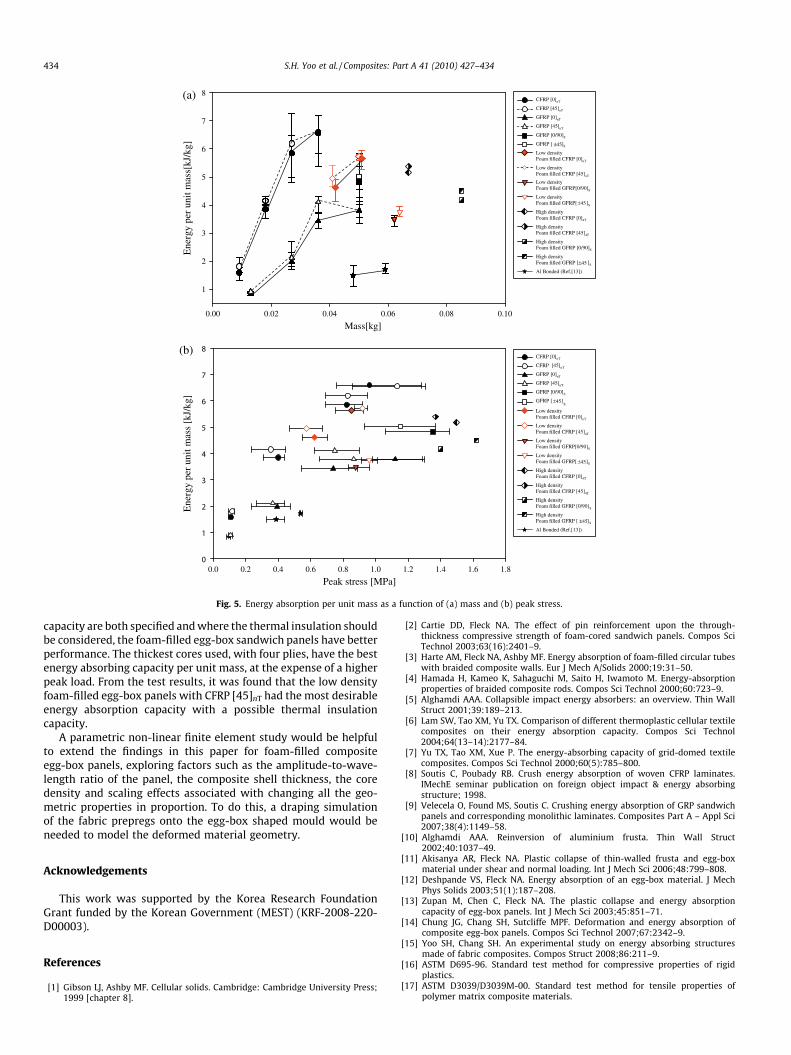
Fig. 5a shows the energy absorption per unit mass of core plot-ted as a function of core mass. The unfilled CFRP cores have thebest energy absorption per unit mass, with the performance ofGFRP about half that of the CFRP. The energy absorption per unitmass improves with increasing mass (i.e. ply number) in the rangeconsidered. Inclusion of foam in the core does not help in this rep-resentation of the energy absorbing behaviour, especially for thethicker egg-box cores, although for the thinnest case ([0]T), foam-filled egg-box cores had almost double the energy absorbancewhen filled with foam. Both materials are significantly better thancorresponding aluminium egg-box cores [13] with the samebonded boundary condition, which are also included on the figure.For comparison with the unconstrained cases, the bonded egg-boxcores have 1.4 times (CFRP) and 1.9 times (GFRP simply-stacked)
higher energy absorption capacities when the cores were stackedby four plies with the same stacking sequence.
Fig. 5b again plots the energy absorption per unit mass, but inthis case as a function of the peak stress (the mean values of theenergy absorption for all the specimens were used for clear repre-sentation). In the case where there is no apparent peak stress, max-imum stress was used in the representation. This measure of plateperformance would be appropriate where not just the amount ofenergy to be absorbed is specified, but also a maximum accelera-tion. Similar conclusions can be drawn from this plot as forFig. 5a about the relative merits of the different materials. Increas-ing ply number corresponds to an increase in both energy absorp-tion per unit mass and peak stress, so that now the selection of theoptimum ply core thickness depends on the trade-off requiredbetween these two design parameters.
6. Concluding discussion
The crushing behaviour and energy absorption of various com-posite egg-box cores have been investigated in this paper. The coreswere fabricated using plain weave CFRP and 4-harness satin weaveGFRP with a range of stacking sequences. In some tests low densityfoam was introduced filling the space in the core. The cores werebonded to face sheets, in contrast to previous work [14] where theface sheets were unbonded. The foam-filled panels did not showan initial peak, but gave a similar plateau response to the uncon-strained panels [14], which it was suggested was due to prematurebuckling of the egg-box core during compression. This suggestedmechanism was supported by the observed differences in collapseresponse seen when changing the density of the foam filler. The en-ergy absorption per unit mass of the cores was calculated and plottedas a function of mass and peak stress. The CFRP panels were found tohave exceptional performance, with GFRP also being good at a lowercost. Modest differences were observed between the different lay-ups. Both materials were significantly better than correspondingaluminium panels. Where the peak load is not critical, the unfilledcores are preferred, while where the peak load and energy absorbing
Ene
rgy
per
unit
mas
s[kJ
/kg]
1
2
3
4
5
6
7
8CFRP [0]nT
CFRP [45]nT
GFRP [0]nT
GFRP [45]nT
GFRP [0/90]S
GFRP [ ]S
Low densityFoam filled CFRP [0]nT
Low densityFoam filled CFRP [45]nT
Low densityFoam filled GFRP[0/90]S
Low densityFoam filled GFRP[ ]S
High densityFoam filled CFRP [0]4T
High densityFoam filled CFRP [45]4T
High densityFoam filled GFRP [0/90]S
High densityFoam filled GFRP [ ]S
Al Bonded (Ref.[13])
45±
45±
45±
Mass[kg]
Peak stress [MPa]
0.00 0.02 0.04 0.06 0.08 0.10
0.0 0.2 0.4 0.6 0.8 1.0 1.2 1.4 1.6 1.8
Ene
rgy
per
unit
mas
s [k
J/kg
]
0
1
2
3
4
5
6
7
8CFRP [0]nT
CFRP [45]nT
GFRP [0]nT
GFRP [45]nT
GFRP [0/90]S
GFRP [ ]sLow densityFoam filled CFRP [0]nT
Low densityFoam filled CFRP [45]nT
Low densityFoam filled GFRP[0/90]S
Low densityFoam filled GFRP[ ]S
High densityFoam filled CFRP [0]4T
High densityFoam filled CFRP [45]4T
High densityFoam filled GFRP [0/90]S
High densityFoam filled GFRP [ ]S
Al Bonded (Ref.[13])
45±
45±
45±
(b)
(a)
Fig. 5. Energy absorption per unit mass as a function of (a) mass and (b) peak stress.
434 S.H. Yoo et al. / Composites: Part A 41 (2010) 427–434
capacity are both specified and where the thermal insulation shouldbe considered, the foam-filled egg-box sandwich panels have betterperformance. The thickest cores used, with four plies, have the bestenergy absorbing capacity per unit mass, at the expense of a higherpeak load. From the test results, it was found that the low densityfoam-filled egg-box panels with CFRP [45]nT had the most desirableenergy absorption capacity with a possible thermal insulationcapacity.
A parametric non-linear finite element study would be helpfulto extend the findings in this paper for foam-filled compositeegg-box panels, exploring factors such as the amplitude-to-wave-length ratio of the panel, the composite shell thickness, the coredensity and scaling effects associated with changing all the geo-metric properties in proportion. To do this, a draping simulationof the fabric prepregs onto the egg-box shaped mould would beneeded to model the deformed material geometry.
Acknowledgements
This work was supported by the Korea Research FoundationGrant funded by the Korean Government (MEST) (KRF-2008-220-D00003).
References
[1] Gibson LJ, Ashby MF. Cellular solids. Cambridge: Cambridge University Press;1999 [chapter 8].
[2] Cartie DD, Fleck NA. The effect of pin reinforcement upon the through-thickness compressive strength of foam-cored sandwich panels. Compos SciTechnol 2003;63(16):2401–9.
[3] Harte AM, Fleck NA, Ashby MF. Energy absorption of foam-filled circular tubeswith braided composite walls. Eur J Mech A/Solids 2000;19:31–50.
[4] Hamada H, Kameo K, Sahaguchi M, Saito H, Iwamoto M. Energy-absorptionproperties of braided composite rods. Compos Sci Technol 2000;60:723–9.
[5] Alghamdi AAA. Collapsible impact energy absorbers: an overview. Thin WallStruct 2001;39:189–213.
[6] Lam SW, Tao XM, Yu TX. Comparison of different thermoplastic cellular textilecomposites on their energy absorption capacity. Compos Sci Technol2004;64(13–14):2177–84.
[7] Yu TX, Tao XM, Xue P. The energy-absorbing capacity of grid-domed textilecomposites. Compos Sci Technol 2000;60(5):785–800.
[8] Soutis C, Poubady RB. Crush energy absorption of woven CFRP laminates.IMechE seminar publication on foreign object impact & energy absorbingstructure; 1998.
[9] Velecela O, Found MS, Soutis C. Crushing energy absorption of GRP sandwichpanels and corresponding monolithic laminates. Composites Part A – Appl Sci2007;38(4):1149–58.
[10] Alghamdi AAA. Reinversion of aluminium frusta. Thin Wall Struct2002;40:1037–49.
[11] Akisanya AR, Fleck NA. Plastic collapse of thin-walled frusta and egg-boxmaterial under shear and normal loading. Int J Mech Sci 2006;48:799–808.
[12] Deshpande VS, Fleck NA. Energy absorption of an egg-box material. J MechPhys Solids 2003;51(1):187–208.
[13] Zupan M, Chen C, Fleck NA. The plastic collapse and energy absorptioncapacity of egg-box panels. Int J Mech Sci 2003;45:851–71.
[14] Chung JG, Chang SH, Sutcliffe MPF. Deformation and energy absorption ofcomposite egg-box panels. Compos Sci Technol 2007;67:2342–9.
[15] Yoo SH, Chang SH. An experimental study on energy absorbing structuresmade of fabric composites. Compos Struct 2008;86:211–9.
[16] ASTM D695-96. Standard test method for compressive properties of rigidplastics.
[17] ASTM D3039/D3039M-00. Standard test method for tensile properties ofpolymer matrix composite materials.
Related Documents