Missouri University of Science and Technology Missouri University of Science and Technology Scholars' Mine Scholars' Mine International Specialty Conference on Cold- Formed Steel Structures (1982) - 6th International Specialty Conference on Cold-Formed Steel Structures Nov 16th, 12:00 AM Composite Steel Deck Diaphragm Slabs -- Design Modes Composite Steel Deck Diaphragm Slabs -- Design Modes Max L. Porter Lowell F. Greimann Follow this and additional works at: https://scholarsmine.mst.edu/isccss Part of the Structural Engineering Commons Recommended Citation Recommended Citation Porter, Max L. and Greimann, Lowell F., "Composite Steel Deck Diaphragm Slabs -- Design Modes" (1982). International Specialty Conference on Cold-Formed Steel Structures. 1. https://scholarsmine.mst.edu/isccss/6iccfss/6iccfss-session9/1 This Article - Conference proceedings is brought to you for free and open access by Scholars' Mine. It has been accepted for inclusion in International Specialty Conference on Cold-Formed Steel Structures by an authorized administrator of Scholars' Mine. This work is protected by U. S. Copyright Law. Unauthorized use including reproduction for redistribution requires the permission of the copyright holder. For more information, please contact [email protected].

Welcome message from author
This document is posted to help you gain knowledge. Please leave a comment to let me know what you think about it! Share it to your friends and learn new things together.
Transcript
Missouri University of Science and Technology Missouri University of Science and Technology
Scholars' Mine Scholars' Mine
International Specialty Conference on Cold-Formed Steel Structures
(1982) - 6th International Specialty Conference on Cold-Formed Steel Structures
Nov 16th, 12:00 AM
Composite Steel Deck Diaphragm Slabs -- Design Modes Composite Steel Deck Diaphragm Slabs -- Design Modes
Max L. Porter
Lowell F. Greimann
Follow this and additional works at: https://scholarsmine.mst.edu/isccss
Part of the Structural Engineering Commons
Recommended Citation Recommended Citation Porter, Max L. and Greimann, Lowell F., "Composite Steel Deck Diaphragm Slabs -- Design Modes" (1982). International Specialty Conference on Cold-Formed Steel Structures. 1. https://scholarsmine.mst.edu/isccss/6iccfss/6iccfss-session9/1
This Article - Conference proceedings is brought to you for free and open access by Scholars' Mine. It has been accepted for inclusion in International Specialty Conference on Cold-Formed Steel Structures by an authorized administrator of Scholars' Mine. This work is protected by U. S. Copyright Law. Unauthorized use including reproduction for redistribution requires the permission of the copyright holder. For more information, please contact [email protected].
COMPOSITE STEEL DECK DIAPHRAGM SLABS--DESIGN MODES
by
Max L. Portera Lowell F. Greimanna
INTRODUCTION
The use of cold-formed steel decking as reinforcement for concrete floor slabs has increased markedly in the past twelve to fifteen years. This kind of composite floor system has two primary advantages: the ability of the steel deck to provide formwork during the casting stages of the concrete and the ability to serve in composite action as tension reinforcement under positive bending. Composite shear transfer devices such as deck embossments or transfer wires provide restraint" for horizontal shear which develops at the deck-to-concrete interface. Many other advantages in addition to those mentioned above are given in Reference 1.
Design recommendations for vertical loads applied to formed metal deck composite slabs have been developed at Iowa State University [2]. The design is controlled primarily by one-way behavior; that is, the relatively large bending stiffness of the slab parallels the longitudinal direction of the deck. Previous research at Iowa State University [1-5] has resulted in design equations [2] for predicting the load capacity of one-way steel-deck-reinforced composite slabs subjected to gravity loads. The predominant mode of failure was found to be shear-bond [3]. The design equation for shear-bond capacity prediction was based on a modification of Equation (11-6) of the American Concrete Institute (ACI) Code [6].
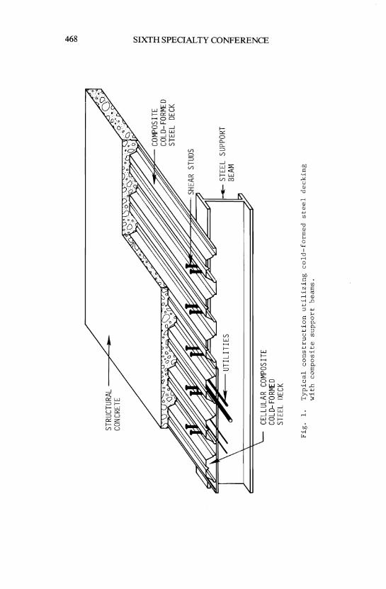
For steel deck floor slabs sUbjected to lateral loads, two types .of composite behavior need to be considered: behavior due to vertical (gravity) loads and behavior due to in-plane loads. A general view of such a floor slab system with both composite deck and studs is shown in Figure 1. Past research on composite steel deck slabs has considered the effect of vertical loads on shear-bond behavior but not the effect of in-plane forces. In addition, the behavior of composite slab-tosupport beam behavior [7,8,9] needs consideration. These concerns led to research at Iowa State University to determine the in-plane shear strength and failure behavior.
aprofessor, Civil Engineering Department, Iowa State University, Ames Iowa.
467
STRU
CTUR
AL
/'
..
CONC
RETE
'~~
COM
POSI
TE
CELL
ULAR
COM
POSI
TE
COLD
-FOR
MED
ST
EEL
flECK
Fig
. 1
. T
yp
ical
co
nstr
ucti
on
u
tili
zin
g
co
ld-f
orm
ed
ste
el
deck
ing
w
ith
co
mp
osi
te
sup
po
rt
beam
s.
COLD
-FOR
MED
ST
EEL
DECK
SUPP
ORT
..,. 0\
00
(Il
S ::t
(Il
dl o ~ ~ 8 ~ g; g
COMPOSITE STEEL DECK DIAPHRAGM SLABS 469
Potential design failure modes are presented in this paper for composite steel-deck-reinforced diaphragm slabs. Whereas previous papers have dealt with steel deck slabs subjected to gravity loads, this paper focuses on such slabs subjected to in-plane shear forces resulting from lateral loads typically produced by wind or earthquakes. All slabs in this investigation were reinforced with cold-formed steel decking. The work described was part of a project sponsored by the National Science Foundation on "Seismic Resistance of Composite Floor Diaphragms" [10].
Previous work on steel deck slabs at Iowa State University sponsored by the American Iron and Steel Institute aided in the formulation of the work in this investigation since certain failure modes observed in gravity-loaded floors are also possible in composite steel deck slabs subjected to diaphragm loading. The objective of this work was to determine the behavioral and strength characteristics of composite steel deck floor systems subjected to in-plane shear. A large test fixture was fabricated on which, to date, nine full-scale composite steel deck slab floors have been tested.
FAILURE MODES
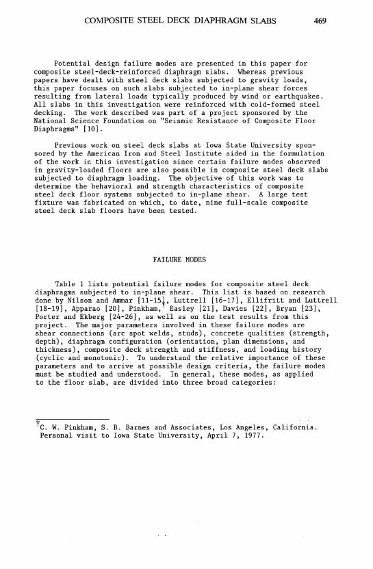
Table 1 lists potential failure modes for composite steel deck diaphragms subjected to in-plane shear. This list is based on research done by Nilson and Ammar [II-1St, Luttrell [16-17], Ellifritt and Luttrell [18-19], Apparao [20], Pinkham, Easley [21], Davies [22], Bryan [23], Porter and Ekberg [24-26], as well as on the test results from this project. The major parameters involved in these failure modes are shear connections (arc spot welds, studs), concrete qualities (strength, depth), diaphragm configuration (orientation, plan dimensions, and thickness), composite deck strength and stiffness, and loading history (cyclic and monotonic). To understand the relative importance of these parameters and to arrive at possible design criteria, the failure modes must be studied and understood. In general, these modes, as applied to the floor slab, are divided into three broad categories:
t C. W. Pinkham, S. B. Barnes and Associates, Los Angeles, California. Personal visit to Iowa State University, April 7, 1977.
470 SIXTH SPECIALTY CONFERENCE
Table 1. Failure modes for composite diaphragms.
l. Composite Diaphragm
a. Shear strength
l. Diagonal tension
2. Parallel to deck corrugations
b. Stability failure
c. Localized failure
2. Deck/Concrete Interface
a. Interfacial shear parallel to the corrugations
b. Interfacial shear perpendicular to the corrugations
1. Pop up (overriding)
2. Deck fold-over
3. Diaphragm/Edge Member Interface
a. Arc spot welds
1. Shearing of weld
2. Tearing and/or buckling of deck around weld
b. Concrete rib
c. Studs (or other shear connectors)
1. Shearing of stud
2. Shear failure of concrete around stud
• overall composite diaphragm action,
• steel deck-to-concrete interface behavior, and
• diaphragm-to-edge member interface failure.
COMPOSITE STEEL DECK DIAPHRAGM SLABS 471
Composite Diaphragm Failures
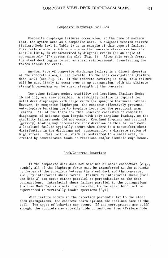
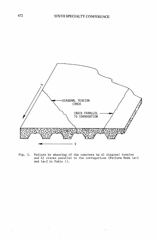
Composite diaphragm failures occur when, at the time of maximum load, the system acts as a composite unit. A diagonal tension failure (Failure Mode la-l in Table 1) is an example of this type of failure. This failure mode, which occurs when the concrete stress reaches its tensile limit, is characterized by diagonal cracks (at an angle of approximately 45°) across the slab (Fig. 2). After this crack forms, the steel deck begins to act as shear reinforcement, transferring the forces across the crack.
Another type of composite diaphragm failure is a direct shearing of the concrete along a line parallel to the deck corrugations (Failure Mode la-2) (see Fig. 2). If the concrete covering is thin, this failure will be most likely to occur over an up corrugation, with the ultimate strength depending on the shear strength of the concrete.
Two other failure modes, stability and localized (Failure Modes Ib and lc), are also possible. A stability failure is typical for metal deck diaphragms with large width-Cor span)-to-thickness ratios. However, in composite diaphragms, the concrete effectively prevents out-of-plane buckling due to in-plane loads for the practical span lengths. All of the tests for this research consisted of composite diaphragms of moderate span lengths with only in-plane loading, so the stability failure mode did not occur. Combined in-plane and vertical (gravity) loading may necessitate consideration of this failure mode. A localized failure typically occurs when there is a nonuniform shear distribution in the diaphragm and, consequently, a discrete region of high stress. This failure, which is restricted to a small area, is created by concentrated loads or reactions and/or flexible edge beams.
Deck/Concrete Interface
If the composite deck does not make use of shear connectors (e.g., studs), all of the diaphragm force must be transferred to the concrete by forces at the interface between the steel deck and the concrete, i.e., by interfacial shear forces. Failure by interfacial shear (Failure Mode 2) can occur either parallel or perpendicular to the deck corrugations. Interfacial shear failure parallel to the corrugations (Failure Mode 2a) is similar in character to the shear-bond failure experienced in vertically loaded specimens [3,5].
When failure occurs in the direction perpendicular to the steel deck corrugations, the concrete bears against the inclined face of the cell. Two types of behavior may occur. If the corrugations are stiff enough, the concrete may actually ride up and over them (Failure Mode
472 SIXTH SPECIALTY CONFERENCE
'-'---DIAGONAL TENSION CRACK
CRACK PARALLEL ------,~ TO CORRUGATION
v
Fig. 2. Failure by shearing of the concrete in a) diagonal tension and b) cracks parallel to the corrugations (Failure Mode la-l and la-2 in Table 1).
COMPOSITE STEEL DECK DIAPHRAGM SLABS 473
2b-1). If they are flexible, the concrete will flatten out the corrugations, a type of behavior comparable to that of a horizontally loaded simple frame (Failure Mode 2b-2). Which mode occurs depends on the stiffness of the deck corrugations and the relative interfacial shear strength in both the transverse and longitudinal directions.
Diaphragm/Edge Member Interface
Edge connections are frequently made with arc spot welds or studs. With the arc spot welds, the load is transferred through the steel deck. Failure at these points would be a direct shearing of the weld (Failure Mode 3a-1), or a buckling and/or tearing of the deck around the weld (Failure Mode 3a-2). With arc spot welds or short studs that do not extend above the up corrugation, a direct shearing of the concrete rib, resembling an unreinforced corbel, could occur (Failure Mode 3b).
With studs that extend above the up corrugation of the steel deck, the shear force is transferred directly onto the concrete above the deck profile. Failure of this form of connection may be a result of stud shear (Failure Mode 3c-1) or concrete failure around the stud (Failure Mode 3c-2). This second form is usually the result of an inadequate amount of concrete in the down corrugation and/or at the edges.
TEST FACILITY
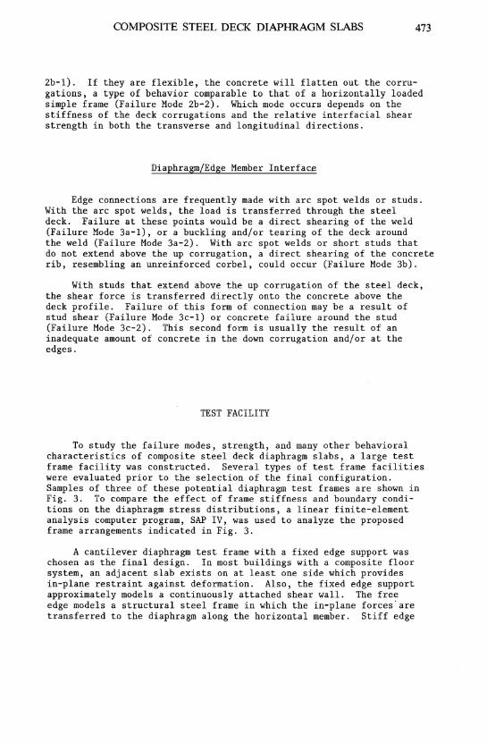
To study the failure modes, strength, and many other behavioral characteristics of composite steel deck diaphragm slabs, a large test frame facility was constructed. Several types of test frame facilities were evaluated prior to the selection of the final configuration. Samples of three of these potential diaphragm test frames are shown in Fig. 3. To compare the effect of frame stiffness and boundary conditions on the diaphragm stress distributions, a linear finite-element analysis computer program, SAP IV, was used to analyze the proposed frame arrangements indicated in Fig. 3.
A cantilever diaphragm test frame with a fixed edge support was chosen as the final design. In most buildings with a composite floor system, an adjacent slab exists on at least one side which provides in-plane restraint against deformation. Also, the fixed edge support approximately models a continuously attached shear wall. The free edge models a structural steel frame in which the in-plane forces' are transferred to the diaphragm along the horizontal member. Stiff edge
474 SIXTH SPECIALTY CONFERENCE
p 2"
(a) Cantilever frame with hinge and roller support pJ2 -2-
pJ2 -2-
(b) Diagonally loaded frame
p
-...J=====n 2"
p 2"
(c) Cantilever frame with a fixed edge support
Fig. 3. Plan view of potential test frames and loading configurations.
COMPOSITE STEEL DECK DIAPHRAGM SLABS 475
beams were used for this test frame because they prod~ce a more uniform shear stress distribution in the test diaphragm than do flexible support beams.
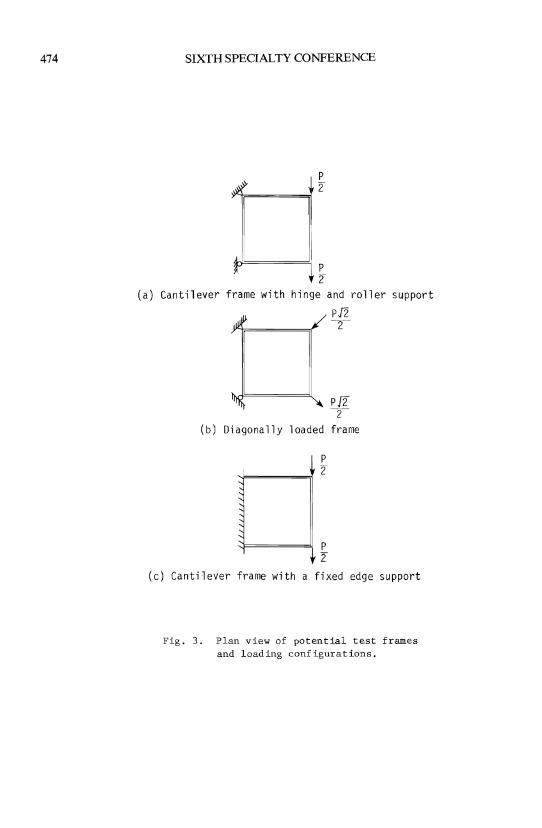
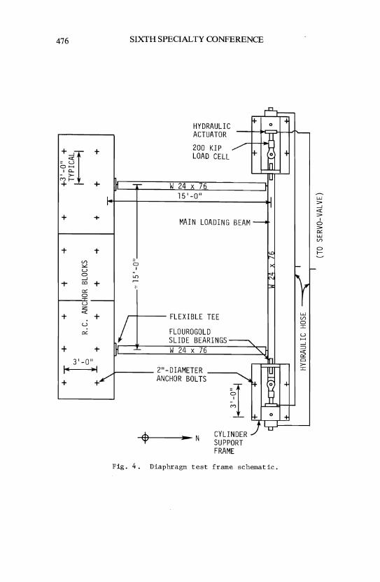
A schematic of the test frame facility appears in Fig. 4. As indicated in the figure, the constructed test frame facility consisted of three large reinforced-concrete reaction blocks (for the fixed edge) and three perimeter-framing beams. The frame was designed for a working load of ±400 kips and a displacement capability of ±6 inches.
The three blocks were used to support one edge of the composite floor diaphragm. An imbedded steel plate, simulating a rigid-beam flange, was used to attach the steel deck of the floor slab to the reaction blocks. The blocks were anchored to ~he laboratory test floor with two-inch diameter high-strength bolts, each post-tensioned to 240 kips. The laboratory test floor was a million pound capacity tie-down floor system.
The edge beams for the test frame were made from wide-flange (W) 24 x 76 steel beams. Web stiffeners were added to prevent rotation of the top flange during large displacements. Friction-type bolted connections were used to join the framing beams together. These bolted connections consisted of flexible "T"-shaped elements instead of pins or hinges. The flexible "T" connections provided a constant frictional restraint during testing.
Two hydraulic double-acting cylinders were used to apply the force to the testing frame. These actuators were front trunnion-mounted and capable of pushing or pulling 200 kips each, giving the test frame a 400-kip capacity. The force was measured by a specially fabricated 200-kip load cell attached in series to the cylinder rod shaft. Pressure gages located at the cylinder ports were used as an indirect measure of the load and served as a visual aid during the testing sequence.
SUMMARY OF TEST SPECIMEN RESULTS
The facilities and instrumentation described in the preceding sections performed very well throughout the test sequence. Nine full-scale composite diaphragm slabs were tested using the cantilevertype test frame. The slabs were 15'4" x 15'4" in out-to-out plan dimensions and ranged in thickness from 3 1/2 inches to 7 1/2 inches (nominally). The first slab specimen tested was used to verify the adequacy of the test frame, controls, instrumentation, and data acquisition systems. No additional supplementary reinforcing was included. All slabs were wet cured for 7-14 days, and then air dried until test time.
476
:51 + 0 ......
, Cl...
- >-CV) f--+ + IH
+ +
+ 1-
Ul :oL U 0 --1
T co + 0:: 0 U-:z: c:c
+ +
,/ u no:
+ + IH 3'-0"
I" .1
+ +/
SIXTH SPECIALTY CONFERENCE
-.-
0 , -lI)
~
1:
....0.....
HYDRAULIC f+- 0
ACTUATOR L..,,u
200 KIP fl-h
LOAD CELL 0 1--
In IU
W 24 x 76 l 15'-0" II
11
MAIN LOADING BEAM~
1\.0 ><
~ :3
FLEXIBLE TEE
FLOUROGOLD SLIDE BEARINGS ~ W 24 x 76
2"-DIAMETER ANCHOR BOLTS
.. N
~
i CYLINDER SUPPORT FRAME
"I In
"lIT ~ ~
w 'n
K- 0
) -u
Fig. 4. Diaphragm test frame schematic.
~ ~
of
-
" r w Ul 0 :r: u ...... --1 ::0 c:c 0:: 0 >-:r:
~
of
r-
w > --1 c:c > , o > 0:: W Ul
o f--
COMPOSITE STEEL DECK DIAPHRAGM SLABS
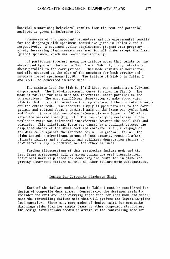
Material summarizing behavioral results from the test and potential analyses is given in Reference 10.
477
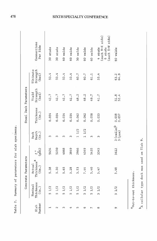
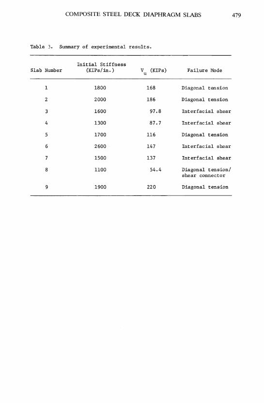
Summaries of the important parameters and the experimental results for the diaphragm slab specimens tested are given in Tables 2 and 3, respectively. A reversed cyclic displacement program with progressively increasing displacements was used for all slabs except the first (pilot) specimen, which was loaded horizontally.
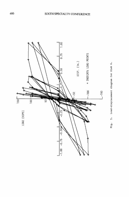
Of particular interest among the failure modes that relate to the shear-bond type of behavior is Mode 2.a in Table 1, i.e., interfacial shear parallel to the corrugations. This mode results in horizontal end slip observed at the edge of the specimen for both gravity and in-plane loaded specimens [3,10]. The failure of Slab 6 in Tables 2 and 3 will be described in more detail.
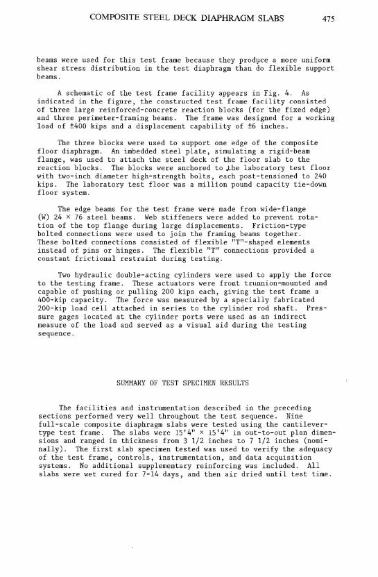
The maximum load for Slab 6, 146.8 kips, was reached at a O.l-inch displacement. The load-displacement curve is shown in Fig. 5. The mode of failure for this slab was interfacial shear parallel to the corrugations. The most significant observation to make about this slab is that no cracks formed on the top surface of the concrete throughout the entire-test. The concrete simply slipped parallel to the corrugations and rotated about a vertical axis as the frame was cycled back and forth. A very high secondary defense plateau formed at 107 kips, after the maximum load (Fig. 5). The load-carrying mechanism in the nonlinear range was frictional interference between the steel deck and concrete. This frictional force was caused by a conflict between the displaced shapes of the steel deck and concrete, i.e., a warpage of the deck cells against the concrete cells. In general, for all the slabs tested, a significant amount of load capacity remained. after ultimate failure and a strength and stiffness degradation similar to that shown in Fig. 5 occurred for the other failures.
Further illustrations of this particular failure mode and the test frame arrangement will be given during the oral presentation. Additional work is planned for combining the tests for in-plane and gravity shear-bond failure as well as other failure mode combinations.
Design for Composite Diaphragm Slabs
Each of the failure modes shown in Table 1 must be considered for design of composite deck slabs. Conceivably, the designer needs to consider and evaluate load carrying capacities for each mode and determine the controlling failure mode that will produce the lowest in-plane load capacity. Since many more modes of design exist for composite diaphragm slabs than for simple beams or other component structures, the design formulations needed to arrive at the controlling mode are
""'"
-...l
Tab
le
2.
Sum
mar
y o
f p
aram
eter
s fo
r sl
ab
sp
ecim
ens.
0
0
Co
ncr
ete
Par
amet
ers
Ste
el
Dec
k P
aram
eter
s
Nom
inal
A
ctu
al
Dec
k Y
ield
U
ltim
ate
S
lah
T
hic
kn
ess
Th
ick
nes
s a f'
Dep
th
Th
ick
nes
s S
tren
gth
S
tren
gth
C
on
nec
tio
ns
Num
ber
(in
. )
(in
. )
(p§
i)
(in
. )
(in
. )
(ksi
) (k
si)
Per
S
ide
1 5
1/2
5
.38
56
34
3 0
.03
4
41
.7
53
.4
30
stu
ds
CJ:l
2 5
1/2
5
.50
52
50
3 0
.03
4
41
.7
53
.4
-30
st
ud
s ~
3 5
1/2
5
.65
40
68
3 0
.03
4
41
.7
53
.4
60
wel
ds
::r: CJ:l
'i:I
4 5
1/2
5
.28
38
49
3 0
.03
4
41
.7
53
.4
60 w
eld
s tI
l (J
-5
5 1
/2
3.5
3
2966
1
1/2
0
.06
2
48
.2
60
.7
30 w
eld
s ~
6 5
1/2
7
.44
45
49
1 1
/2
0.0
62
4
8.2
6
0.7
60
w
eld
s >-<
8 7
5 1
/2
5.4
0
5435
3
0.0
58
4
9.7
6
1.1
60
w
eld
s ~ tI
l 8
5 1
/2
5.4
7
3345
3
0.0
35
4
1.7
5
3.4
4
stu
ds
:;0
tIl
(eac
h N
-S
sid
e)
g 6
stu
ds
(eac
h E
-W
sid
e)
9 5
1/2
5
.48
54
12
3 (c
ell
s)b
0
.05
8
51
.8
63
.2
60 w
eld
s 3
(pan
) 0
.05
7
52
.4
64
.9
aO
ut-
to-o
ut
thic
kn
ess
.
b A c
ell
ula
r ty
pe
dec
k w
as
use
d
on
Sla
b
9.
COMPOSITE STEEL DECK DIAPHRAGM SLABS 479
Table 3. Summary of experimental results.
Initial Stiffness Slab Number (KIPs/in. ) V (KIPs) Failure Mode u
1 1800 168 Diagonal tension
2 2000 186 Diagonal tension
3 1600 97.8 Interfacial shear
4 1300 87.7 Interfacial shear
5 1700 116 Diagonal tension
6 2600 147 Interfacial shear
7 1500 137 Interfacial shear
8 1100 54.4 Diagonal tension/ shear connector
9 1900 220 Diagonal tension
150
LOAD
(K
IPS)
100
DIS
P.
(in
.)
-100
+
IN
DICA
TE L
OAD
POIN
TS
-150
Fig
. 5
. L
oad
-dis
pla
cem
en
t d
iag
ram
fo
r S
lab
6
.
""" 00
o [f
J S ::r: [fJ ril o ~ -< 8 ~ ~ g
COMPOSITE STEEL DECK DIAPHRAGM SLABS 481
more lengthy. The design mode becomes even more complex when the loading consists of gravity combined with in-plane loading. Work is underway at Iowa State University to investigate such analyses further and to design recommendations for composite steel deck diaphragm slabs to supplement those design recommendations in Reference 2 for gravityloaded steel deck slabs.
SUMMARY
The test facility described herein was designed and constructed for testing composite steel deck diaphragms. Nine full-scale (IS-foot square) diaphragms were tested using a cantilever-type test frame. The tests followed a displacement program controlled by an MTS closedloop system.
All slabs were constructed using corrugated, cold-formed steel decking as composite reinforcement for the concrete slabs. The results of the tests will eventually be used to formulate design recommendations for in-plane shear strength for steel deck reinforced slabs. These design recommendations are intended to supplement those proposed in Reference 2 for gravity-loaded steel deck slabs. The results also should aid in establishing test standards for floor slab diaphragm tests and associated instrumentation.
In conclusion, the test frame facility described in this paper performed very well. The failure modes given in Table 1 provide the basis for future design formulations for composite steel deck reinforced floor slabs.

482 SIXTH SPECIALTY CONFERENCE
REFERENCES
1. Porter, M. L. and Ekberg, C. E., Jr., "Compendium of ISU Research Conducted on Cold-Formed Steel-Deck-Reinforced Slab Systems," Bulletin 200, Engineering Research Institute, Iowa State University, December 1978.
2. Porter, M. L. and Ekberg, C. E., Jr., "Design Recommendations for Steel Deck Floor Slabs," Journal of the Structural Division, ASCE, Vol. 102, No. ST11, Proc. Paper 12528, November 1976, pp. 2121-2136.
3. Porter, M. L., Ekberg, C. E., Jr., Greimann, L. F. and Elleby, H. A., "Shear-Bond Analysis of Steel-Deck-Reinforced Slabs," Journal of the Structural Division, ASCE, Vol. 102, No. ST12, Proc. Paper 12611, December 1976, pp. 2255-2268.
4. Porter, M. 1. and Ekberg, C. E., Jr., "Design vs Test Results for Steel Deck Floor Slabs," Proceedings of Third Specialty Conference on Cold-Formed Steel Structures, Department of Civil Engineering, University of Missouri-Rolla, October 1975, pp. 293-812.
5. Porter, M. L. and Ekberg, C. E., Jr., "Behavior of Steel-Deck Reinforced Slabs," Journal of the Structural Division, ASCE, Vol. 103, No. ST3, Proc. Paper 12826, March 1977, pp. 663-677.
6. American Concrete Institute, Building Code Requirements for Reinforced Concrete, ACI Standard 318-77, Detroit, Michigan: American Concrete Institute, 1977.
7. Grant, J. A., Fisher, J. W. and Slutter, R. G., "Composite Beams with Formed Steel Deck," AISC Engineering Journal, American Institute of Steel Construction, First Quarter 1977, pp. 24-43.
8. Ollgaard, J. G., Slutter, R. G. and Fisher, J. W., "Shear Strength of Stud Connectors in Lightweight and Normal-Weight Concrete," AISC Engineering Journal, American Institute of Steel Construction, 8, No.2, April 1971, pp. 55-64.
9. American Institute of Steel Construction, Inc., Specification for the Design, Fabrication and Erection of Structural Steel for Build~, New York: AISC, 1980.
10. Porter, M. L. and Greimann, L. F., "Seismic Resistance of Composite Floor Diaphragms," ISU-ERI-Ames-80133, Iowa State University, Ames, Iowa, Final Report submitted to National Science Foundation, May 1980, 174 pp.
COMPQSITE STEEL DECK DIAPHRAGM SLABS
11. Nilson, A. H., "Shear Diaphragms of Light Gage Steel," Journal of the Structural Division, ASCE 86, No. ST11 (November 1960), 111-140.
483
12. Nilson, A. H., "Diaphragm Action of Light Gage Steel Construction," AISI Regional Technical Paper (1960).
13. Nilson, A. H. and Ammar, A. R., "Finite Analysis of Metal Deck Shear Diaphragms," Journal of the Structural Division, ASCE 100, No. ST4 (April 1974), 711-726.
14. Ammar, A. A. and Nilson, A. H., "Analysis of Light Gage Steel Shear Diaphragms, Part I," Department of Structural Engineering, Research Report 350, Cornell University (August 1972).
15. Ammar, A. A. and Nilson, A. H., "Analysis of Light Gage Steel Shear Diaphragms, Part II," Department of Structural Engineering, Research Report 351, Cornell University (August 1973).
16. Luttrell, L. D., "Strength and Behavior of Light Gage Steel Shear Diaphragms," Department of Structural Engineering, Cornell Engineering Research Bulletin No. 67-1, Cornell University (July 1967).
17. Luttrell, L. D., "Structural Performance of Light Gage Steel Diaphragms," Department of Structural Engineering, Research Report 319, Cornell University (August 1965).
18. Ellifritt, D. S. and Luttrell, L. D., "Strength and Stiffness of Steel Deck Shear Diaphragms," Proceedings of First Specialty Conference on Cold-Formed Steel Structures, Department of Civil Engineering, University of Missouri-Rolla (August 19-20, 1971).
19. Ellifritt, D. S. and Luttrell, 1. D., "Strength and Stiffness of Steel Deck Subjected to In-Plane Loading," West Virginia University Civil Engineering Studies Report 2011, West Virginia University, Morgantown, West Virginia (i968).
20. Apparao, T. V., "Tests on Light Gage Steel Diaphragms," Department of Structural Engineering, Research Report 328, Cornell University, (December 1966).
21. Easley, J. T., "Buckling Formulas for Corrugated Metal Shear Diaphragms," Journal of the Structural Division, ASCE 101, No. ST7, Proc. Paper 11429 (July 1975), 1403-1417.
22. Davies, M. J., "Calculation of Steel Diaphragms Behavior," Journal of the Structural Division, ASCE 102, No. ST7 (July 1976), 1431-1445.
23. Bryan, E. R., The Stressed Skin Design of Steel Buildings. London, England: Crosly Lockwood Staples (1973).
484 SIXTH SPECIALTY CONFERENCE
24. Porter, M. 1. and Ekberg, C. E., Jr., "Investigation of Cold-Formed Steel-Deck-Reinforced Concrete Floor Slabs," Proceedings of First Specialty Conference on Cold-Formed Steel Structures, Department of Civil Engineering, University of Missouri-Rolla (August 19-20, 1971).
25. Porter, M. 1. and Ekberg, C. E., J r., "Summary of Full-Scale Laboratory Tests of Concrete Slabs Reinforced with Cold-Formed Steel Decking," Preliminary Report, International Association for Bridge and Structural Engineering, Ninth Congress, Zurich, Switzerland (May 8-12, 1972).
26. Porter, M. L., Commentary on the Tentative Recommendations for the Design of Composite Steel Deck Slabs. Manual. Washington, D.C.: American Iron and Steel Institute (December 1974).
Related Documents