Composable Process Elements for Developing COTS-Based Applications Barry Boehm, Dan Port, Ye Yang, Jesal Bhuta, Chris Abts* University of Southern California, Texas A&M University* {boehm, dport, yey, jesal}@cse.usc.edu, [email protected] Abstract Data collected from five years of developing e-service applications at USC-CSE reveals that an increasing fraction have been commercial-off-the-shelf (COTS)- Based Application (CBA) projects: from 28% in 1997 to 60% in 2001. Data from both small and large CBA projects show that CBA effort is primarily distributed among the three activities of COTS assessment, COTS tailoring, and glue code development and integration, with wide variations in their distribution across projects. We have developed a set of data-motivated composable process elements, in terms of these three activities, for developing CBA's as well an overall decision framework for applying the process elements. We present data regarding the movement towards CBA's and effort distribution among them; we then proceed to describe the decision framework and to present a real-world example showing how it operates within the WinWin Spiral process model generator to orchestrate, execute, and adapt the process elements to changing project circumstances. 1. Introduction In his ICSE 2002 keynote address [3], Robert Balzer issued a challenge to the software engineering community to provide better methods for dealing with COTS-based software systems, and to present them at subsequent ICSE’s. This paper provides a partial response to this challenge. It presents some data that we have found useful in understanding COTS-based application (CBA) trends and effort distributions. The COTS effort distributions and sequences also suggest a framework for the primary contributions of the paper: a set of composable process elements and a decision framework for using them in the development of CBA’s. Traditional sequential requirements-design-code-test (waterfall) processes do not work for CBA’s [11], simply because the decision to use a COTS product constitutes acceptance of many, if not most, of the requirements that led to the product, and to its design and implementation. In fact, it is most often the case that a COTS product’s capabilities will drive the “required” feature set for the new product rather than the other way around, though the choice of COTS products to be used should be driven by the new project’s initial set of “most significant requirements.” Additionally, the volatility of COTS products [9] introduces a great deal of recursion and concurrency into CBA processes. Some recent CBA process models have partially addressed these issues by adding CBA extensions to a sequential process framework [8]. These work in some situations, but not in others where the requirements, architecture, and COTS choices evolve concurrently; the example in Section 4 illustrates this point. Other process frameworks such as the spiral model [5] and the SEI Evolutionary Process for Integrating COTS- Based Systems (EPIC) process [2] provide suitably flexible and concurrent frameworks for CBA processes. However, they have not, to date, provided a specific decision framework for navigating through the option space in developing CBA’s. They identify key activities (evaluate alternatives; identify and resolve risks; accumulate specific kinds of knowledge; increase stakeholder buy-in; make incremental decisions that shrink the trade space), but leave their sequencing to the individual CBA developer. The decision framework presented here is based on our experience in analyzing large CBA’s in the course of gathering empirical data for the Constructive CBA cost model (COCOTS), a COTS counterpart to COCOMOII [1,6], and our experience developing and analyzing several dozen e-services CBA’s for USC’s Information Services Division and its Center for Scholarly Technology [4]. Section 2 provides relevant definitions and context. Section 3 presents the CBA process decision framework and composable process elements. Section 4 presents an update to the WinWin Spiral Model, and illustrates, via an actual example, how it, the CBA decision framework, and the composable CBA process elements were used to converge on the most appropriate composite CBA process for that example. Section 5 provides conclusions. 2. Definitions and Context 2.1 Definitions We adopt the SEI COTS-Based System Initiative’s definition [7] of a COTS product: A product that is: Sold, leased, or licensed to the general public; Offered by a vendor trying to profit from it; Supported and evolved by the vendor, who retains the intellectual property rights; Available in multiple identical copies; Used without source code modification. We also follow the SEI in defining a COTS-Based System very generally as “any system, which includes one Proceedings of the 2003 International Symposium on Empirical Software Engineering (ISESE’03) 0-7695-2002-2/03 $ 17.00 © 2003 IEEE

Welcome message from author
This document is posted to help you gain knowledge. Please leave a comment to let me know what you think about it! Share it to your friends and learn new things together.
Transcript
Composable Process Elements for Developing COTS-Based Applications Barry Boehm, Dan Port, Ye Yang, Jesal Bhuta, Chris Abts*
University of Southern California, Texas A&M University*
{boehm, dport, yey, jesal}@cse.usc.edu, [email protected]
AbstractData collected from five years of developing e-service
applications at USC-CSE reveals that an increasing
fraction have been commercial-off-the-shelf (COTS)-
Based Application (CBA) projects: from 28% in 1997 to
60% in 2001. Data from both small and large CBA
projects show that CBA effort is primarily distributed
among the three activities of COTS assessment, COTS
tailoring, and glue code development and integration,
with wide variations in their distribution across projects.
We have developed a set of data-motivated composable
process elements, in terms of these three activities, for
developing CBA's as well an overall decision framework
for applying the process elements. We present data
regarding the movement towards CBA's and effort
distribution among them; we then proceed to describe
the decision framework and to present a real-world
example showing how it operates within the WinWin
Spiral process model generator to orchestrate, execute,
and adapt the process elements to changing project
circumstances.
1. Introduction In his ICSE 2002 keynote address [3], Robert Balzer
issued a challenge to the software engineering community
to provide better methods for dealing with COTS-based
software systems, and to present them at subsequent
ICSE’s. This paper provides a partial response to this
challenge. It presents some data that we have found
useful in understanding COTS-based application (CBA)
trends and effort distributions. The COTS effort
distributions and sequences also suggest a framework for
the primary contributions of the paper: a set of
composable process elements and a decision framework
for using them in the development of CBA’s.
Traditional sequential requirements-design-code-test
(waterfall) processes do not work for CBA’s [11], simply
because the decision to use a COTS product constitutes
acceptance of many, if not most, of the requirements that
led to the product, and to its design and implementation.
In fact, it is most often the case that a COTS product’s
capabilities will drive the “required” feature set for the
new product rather than the other way around, though the
choice of COTS products to be used should be driven by
the new project’s initial set of “most significant
requirements.” Additionally, the volatility of COTS
products [9] introduces a great deal of recursion and
concurrency into CBA processes.
Some recent CBA process models have partially
addressed these issues by adding CBA extensions to a
sequential process framework [8]. These work in some
situations, but not in others where the requirements,
architecture, and COTS choices evolve concurrently; the
example in Section 4 illustrates this point.
Other process frameworks such as the spiral model [5]
and the SEI Evolutionary Process for Integrating COTS-
Based Systems (EPIC) process [2] provide suitably
flexible and concurrent frameworks for CBA processes.
However, they have not, to date, provided a specific
decision framework for navigating through the option
space in developing CBA’s. They identify key activities
(evaluate alternatives; identify and resolve risks;
accumulate specific kinds of knowledge; increase
stakeholder buy-in; make incremental decisions that
shrink the trade space), but leave their sequencing to the
individual CBA developer.
The decision framework presented here is based on
our experience in analyzing large CBA’s in the course of
gathering empirical data for the Constructive CBA cost
model (COCOTS), a COTS counterpart to COCOMOII
[1,6], and our experience developing and analyzing
several dozen e-services CBA’s for USC’s Information
Services Division and its Center for Scholarly
Technology [4].
Section 2 provides relevant definitions and context.
Section 3 presents the CBA process decision framework
and composable process elements. Section 4 presents an
update to the WinWin Spiral Model, and illustrates, via
an actual example, how it, the CBA decision framework,
and the composable CBA process elements were used to
converge on the most appropriate composite CBA process
for that example. Section 5 provides conclusions.
2. Definitions and Context 2.1 Definitions
We adopt the SEI COTS-Based System Initiative’s
definition [7] of a COTS product: A product that is:
Sold, leased, or licensed to the general public;
Offered by a vendor trying to profit from it;
Supported and evolved by the vendor, who retains
the intellectual property rights;
Available in multiple identical copies;
Used without source code modification.
We also follow the SEI in defining a COTS-Based
System very generally as “any system, which includes one
Proceedings of the 2003 International Symposium on Empirical Software Engineering (ISESE’03) 0-7695-2002-2/03 $ 17.00 © 2003 IEEE
or more COTS products.” This includes most current
systems, including many which treat a COTS operating
system and other utilities as a relatively stable platform on
which to build applications. Such systems can be
considered “COTS-based systems,” as most of their
executing instructions come from COTS products, but
COTS considerations do not affect the development
process very much.
To provide a focus on the types of applications for
which COTS considerations do affect the development
process, we define a COTS-Based Application as a system
for which at least 30% of the end-user functionality (in
terms of functional elements: inputs, outputs, queries,
external interfaces, internal files) is provided by COTS
products, and at least 10 % of the development effort is
devoted to COTS considerations. The numbers 30% and
10% are not sacred quantities, but approximate behavioral
CBA boundaries observed in the application projects.
There was a significant gap observed in COTS-related
effort reporting. The projects observed either reported
less than 2% or over 10% COTS-related effort, but never
between 2-10%.
In our six years of iteratively defining, developing,
gathering project data for, and calibrating COCOTS cost
estimation model, we identified three primary sources of
project effort due to CBA development considerations.
These are defined in COCOTS as follows:
COTS Assessment is the activity whereby COTS
products are evaluated and selected as viable
components for a user application.
COTS Tailoring is the activity whereby COTS
software products are configured for use in a specific
context. This definition is similar to the SEI
definition of “tailoring” [10].
COTS Glue Code development and integration is the
activity whereby code is designed, developed, and
used to ensure that COTS products satisfactorily
interoperate in support of the user application.
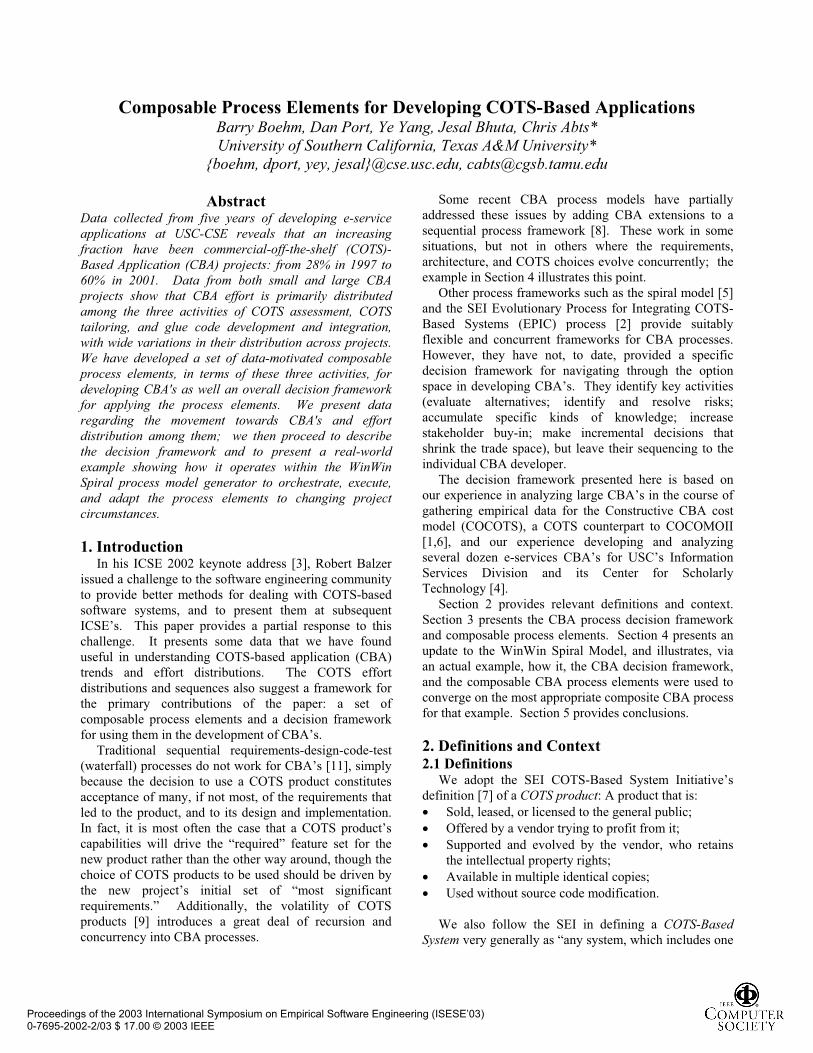
2.2 CBA Growth Trend An increasing fraction of CBA projects have been
observed in over five years’ USC-CSE e-services project
data. As seen in figure 2.1, the CBA fraction has
increased from 28% in 1997 to 60% in 2001.
Major considerations for adopting COTS products in
these projects are: 1) the clients’ request, 2) the schedule
constraint, 3) compliance with organization standards,
and 4) the budget constraint. The primary reason for the
growth in COTS content has, however, been the large
increase in the number of COTS products providing
application functions. In 1997, most of the teams were
programming their own search engines and Web
crawlers, for example; by 2001 these functions were
being accomplished by COTS products.
Some of our USC-CSE affiliates have reported similar
qualitative trends, but this is the first quantitative data
they and we have seen on the rate of increase of CBA
projects under any consistent definition and in any
application sector (e-services applications probably have
higher rates of increase than many other sectors). We
have experienced many notable effects of this increase:
for example, programming skills are necessary but not
sufficient for developing CBA’s (see also 8,9,10,11]).
fraction of projects satisfying (30%, 10%) CBA criteria
0
0.1
0.2
0.3
0.4
0.5
0.6
0.7
1997 1998 1999 2000 2001
Year
Figure 2.1 CBA Growth in Small E-Service Projects
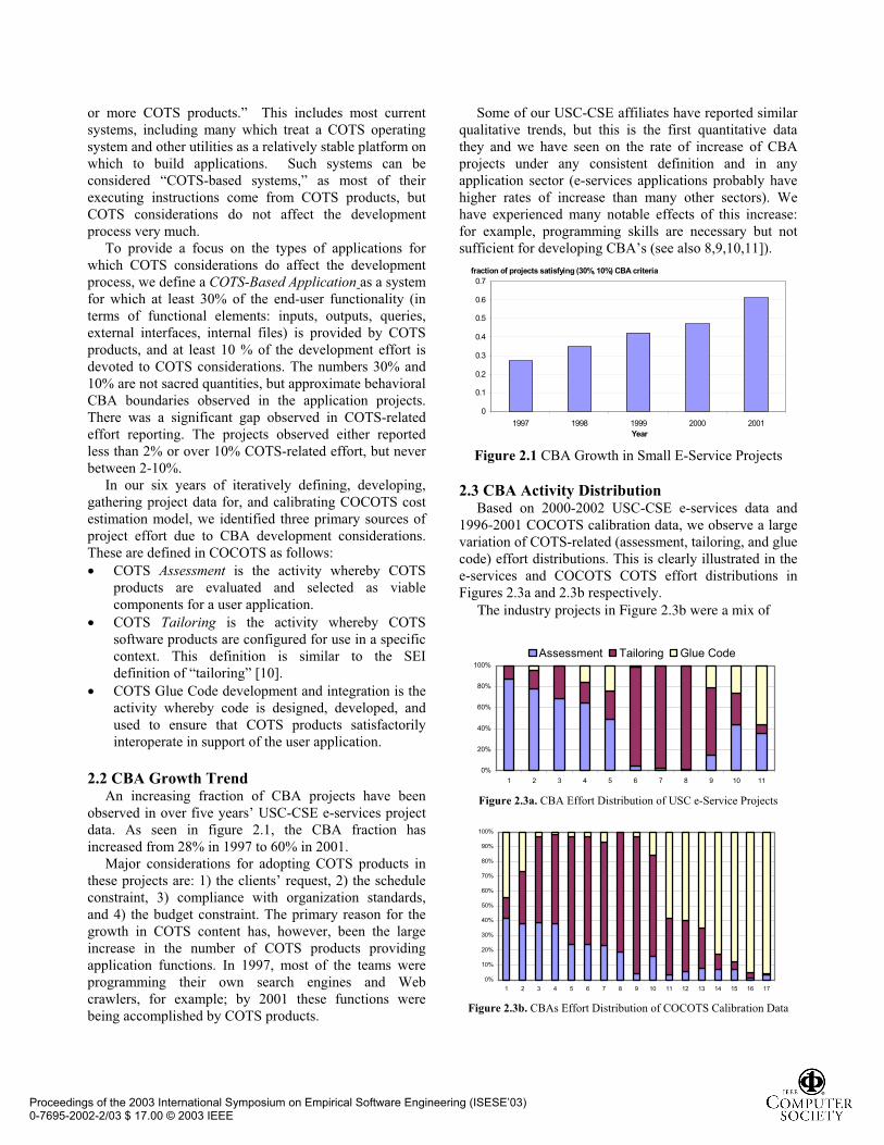
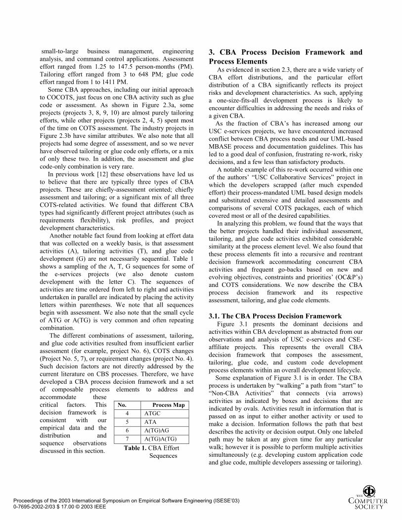
2.3 CBA Activity Distribution Based on 2000-2002 USC-CSE e-services data and
1996-2001 COCOTS calibration data, we observe a large
variation of COTS-related (assessment, tailoring, and glue
code) effort distributions. This is clearly illustrated in the
e-services and COCOTS COTS effort distributions in
Figures 2.3a and 2.3b respectively.
The industry projects in Figure 2.3b were a mix of
0%
20%
40%
60%
80%
100%
1 2 3 4 5 6 7 8 9 10 11
Assessment Tailoring Glue Code
Figure 2.3a. CBA Effort Distribution of USC e-Service Projects
0%
10%
20%
30%
40%
50%
60%
70%
80%
90%
100%
1 2 3 4 5 6 7 8 9 10 11 12 13 14 15 16 17
Figure 2.3b. CBAs Effort Distribution of COCOTS Calibration Data
Proceedings of the 2003 International Symposium on Empirical Software Engineering (ISESE’03) 0-7695-2002-2/03 $ 17.00 © 2003 IEEE
No. Process Map
4 ATGC
5 ATA
6 A(TG)AG
7 A(TG)A(TG)
Table 1. CBA Effort
Sequences
small-to-large business management, engineering
analysis, and command control applications. Assessment
effort ranged from 1.25 to 147.5 person-months (PM).
Tailoring effort ranged from 3 to 648 PM; glue code
effort ranged from 1 to 1411 PM.
Some CBA approaches, including our initial approach
to COCOTS, just focus on one CBA activity such as glue
code or assessment. As shown in Figure 2.3a, some
projects (projects 3, 8, 9, 10) are almost purely tailoring
efforts, while other projects (projects 2, 4, 5) spent most
of the time on COTS assessment. The industry projects in
Figure 2.3b have similar attributes. We also note that all
projects had some degree of assessment, and so we never
have observed tailoring or glue code only efforts, or a mix
of only these two. In addition, the assessment and glue
code-only combination is very rare.
In previous work [12] these observations have led us
to believe that there are typically three types of CBA
projects. These are chiefly-assessment oriented; chiefly
assessment and tailoring; or a significant mix of all three
COTS-related activities. We found that different CBA
types had significantly different project attributes (such as
requirements flexibility), risk profiles, and project
development characteristics.
Another notable fact found from looking at effort data
that was collected on a weekly basis, is that assessment
activities (A), tailoring activities (T), and glue code
development (G) are not necessarily sequential. Table 1
shows a sampling of the A, T, G sequences for some of
the e-services projects (we also denote custom
development with the letter C). The sequences of
activities are time ordered from left to right and activities
undertaken in parallel are indicated by placing the activity
letters within parentheses. We note that all sequences
begin with assessment. We also note that the small cycle
of ATG or A(TG) is very common and often repeating
combination.
The different combinations of assessment, tailoring,
and glue code activities resulted from insufficient earlier
assessment (for example, project No. 6), COTS changes
(Project No. 5, 7), or requirement changes (project No. 4).
Such decision factors are not directly addressed by the
current literature on CBS processes. Therefore, we have
developed a CBA process decision framework and a set
of composable process elements to address and
accommodate these
critical factors. This
decision framework is
consistent with our
empirical data and the
distribution and
sequence observations
discussed in this section.
3. CBA Process Decision Framework and
Process Elements As evidenced in section 2.3, there are a wide variety of
CBA effort distributions, and the particular effort
distribution of a CBA significantly reflects its project
risks and development characteristics. As such, applying
a one-size-fits-all development process is likely to
encounter difficulties in addressing the needs and risks of
a given CBA.
As the fraction of CBA’s has increased among our
USC e-services projects, we have encountered increased
conflict between CBA process needs and our UML-based
MBASE process and documentation guidelines. This has
led to a good deal of confusion, frustrating re-work, risky
decisions, and a few less than satisfactory products.
A notable example of this re-work occurred within one
of the authors’ “USC Collaborative Services” project in
which the developers scrapped (after much expended
effort) their process-mandated UML based design models
and substituted extensive and detailed assessments and
comparisons of several COTS packages, each of which
covered most or all of the desired capabilities.
In analyzing this problem, we found that the ways that
the better projects handled their individual assessment,
tailoring, and glue code activities exhibited considerable
similarity at the process element level. We also found that
these process elements fit into a recursive and reentrant
decision framework accommodating concurrent CBA
activities and frequent go-backs based on new and
evolving objectives, constraints and priorities’ (OC&P’s)
and COTS considerations. We now describe the CBA
process decision framework and its respective
assessment, tailoring, and glue code elements.
3.1. The CBA Process Decision Framework Figure 3.1 presents the dominant decisions and
activities within CBA development as abstracted from our
observations and analysis of USC e-services and CSE-
affiliate projects. This represents the overall CBA
decision framework that composes the assessment,
tailoring, glue code, and custom code development
process elements within an overall development lifecycle.
Some explanation of Figure 3.1 is in order. The CBA
process is undertaken by “walking” a path from “start” to
“Non-CBA Activities” that connects (via arrows)
activities as indicated by boxes and decisions that are
indicated by ovals. Activities result in information that is
passed on as input to either another activity or used to
make a decision. Information follows the path that best
describes the activity or decision output. Only one labeled
path may be taken at any given time for any particular
walk; however it is possible to perform multiple activities
simultaneously (e.g. developing custom application code
and glue code, multiple developers assessing or tailoring).
Proceedings of the 2003 International Symposium on Empirical Software Engineering (ISESE’03) 0-7695-2002-2/03 $ 17.00 © 2003 IEEE
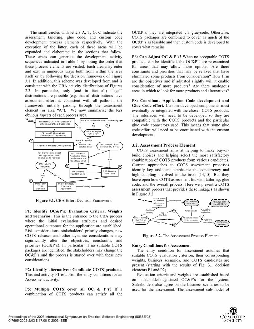
The small circles with letters A, T, G, C indicate the
assessment, tailoring, glue code, and custom code
development process elements respectively. With the
exception of the latter, each of these areas will be
expanded and elaborated in the sections that follow.
These areas can generate the development activity
sequences indicated in Table 1 by noting the order that
these process elements are visited. Each area may enter
and exit in numerous ways both from within the area
itself or by following the decision framework of Figure
3.1. In addition, this scheme was developed from and is
consistent with the CBA activity distributions of Figures
2.3. In particular, only (and in fact all) “legal”
distributions are possible (e.g. that all distributions have
assessment effort is consistent with all paths in the
framework initially passing through the assessment
element (or area “A”). We now summarize the less
obvious aspects of each process area.
P1: Identi fy OC & P's: Eval uat ionCriteria, Weights and Scenarios
P2: Identi fy alt ernatives:Candidate COTS products
P4: Tailoring
Requi red?
P6: Can AdjustOC & P's?
P7: Custom Developm ent
C
A
G
P11: Tailor
CO TSproducts
P12: P roducti ze,
T ransit ionApplication
YesNo
Full COTS solution best
No Appli cat ion Codeor Glue Code Requi red
No
Yes No
None Acceptable
C
T
Part ial CO TSSol ution Best
P5: Mul tiple COTScover all OC & P ’s?
P8: CoordinateApplication Codedevel opment and
Glue Code effort
P10: Devel opGlue Code
P9: DevelopCustom Code
Start
P3: Assess Candidate COT S products
Yes
Dep loy
Dep loy
Figure 3.1. CBA Effort Decision Framework
P1: Identify OC&P’s: Evaluation Criteria, Weights
and Scenarios. This is the entrance to the CBA process
where the initial evaluation attributes and desired
operational outcomes for the application are established.
Risk considerations, stakeholders’ priority changes, new
COTS releases and other dynamic considerations may
significantly alter the objectives, constraints, and
priorities (OC&P’s). In particular, if no suitable COTS
packages are identified, the stakeholders may change the
OC&P’s and the process is started over with these new
considerations.
P2: Identify alternatives: Candidate COTS products.
This and activity P1 establish the entry conditions for an
Assessment activity.
P5: Multiple COTS cover all OC & P’s? If a
combination of COTS products can satisfy all the
OC&P’s, they are integrated via glue-code. Otherwise,
COTS packages are combined to cover as much of the
OC&P’s as feasible and then custom code is developed to
cover what remains.
P6: Can Adjust OC & P's? When no acceptable COTS
products can be identified, the OC&P’s are re-examined
for areas that may allow more options. Are there
constraints and priorities that may be relaxed that have
eliminated some products from consideration? How firm
are the objectives and if adjusted slightly will it enable
consideration of more products? Are there analogous
areas in which to look for more products and alternatives?
P8: Coordinate Application Code development and
Glue Code effort. Custom developed components must
eventually be integrated with the chosen COTS products.
The interfaces will need to be developed so they are
compatible with the COTS products and the particular
glue code connectors used. This means that some glue
code effort will need to be coordinated with the custom
development.
3.2. Assessment Process Element COTS assessment aims at helping to make buy-or-
build choices and helping select the most satisfactory
combination of COTS products from various candidates.
Current approaches to COTS assessment processes
identify key tasks and emphasize the concurrency and
high coupling involved in the tasks [14,15]. But they
leave open how COTS assessment fits with tailoring, glue
code, and the overall process. Here we present a COTS
assessment process that provides these linkages as shown
in Figure 3.2: A1: Init ial Filtering
of Candidates
with respect tocriteri a
Candidates
remaining
Yes, Tail or
Yes,G lue Code
No
None Acceptable
None Acceptable
F ull-COTS
soluti on best
Parti al-CO TS solut ion best
A3: E val uate rem aining
COT S candidates
G
T
A2: Need Tailoring,Glue Code f or
Evaluat ion?
P 6: Can AdjustOC & P's?
P5: Mult iple COT Scover all O C & P ’s?
P4: Tai loring
Required?
Figure 3.2. The Assessment Process Element
Entry Conditions for Assessment
The entry condition for assessment assumes that
suitable COTS evaluation criterion, their corresponding
weights, business scenarios, and COTS candidates are
present (starting with the results of Fig. 3.1 decision
elements P1 and P2).
Evaluation criteria and weights are established based
on stakeholder-negotiated OC&P’s for the system.
Stakeholders also agree on the business scenarios to be
used for the assessment. The assessment sub-model of
Proceedings of the 2003 International Symposium on Empirical Software Engineering (ISESE’03) 0-7695-2002-2/03 $ 17.00 © 2003 IEEE
COCOTS has collected an extensive list of attributes used
in COTS evaluation [1,6].
A1: Initial Filtering. Initial assessment tries to quickly
filter out the unacceptable COTS packages based on the
evaluation criteria. The objective of this activity is to
reduce the number of COTS candidates needing to be
evaluated in detail. If no available COTS products pass
this filtering, this assessment element ends up at the
“none acceptable” exit.
A2: Tailoring or Glue Code Needed for Evaluation.
The remaining COTS candidates from initial filtering will
undergo more detailed assessment. To do so, some COTS
products need to be tailored (e.g., to assess usability), and
some need to be integrated by glue code development
(e.g., to assess interoperability).
A3: Detailed Assessment. The focus of detailed
assessment is to collect data/information about each
COTS candidate against evaluation criteria from pre-
designed business scenarios, analyze the data and make
decision trade-offs. Some useful techniques are listed
here:
1. Use a market watch activity to get the latest COTS
information, and collect COTS information from
its current users to gain first hand COTS
experience from its current user group.
2. Assess vendor supportability to address life cycle
issues such as system refresh and maintenance.
3. Develop, instrument, and evaluate prototypes,
benchmarks, simulations, or analytic models to
analyze key performance parameters and tradeoffs.
A screening matrix or analytic hierarchy process is a
useful and common approach to analyze collected
evaluation data. The evaluation criteria and COTS
candidates work as the columns and rows of the matrix
respectively. The final score for a particular COTS
candidate is the weighted sum of its points across all of
the evaluation criteria. A ranking of all COTS candidates
will be produced to help making the COTS decision.
However, often a more focused analysis such as a gap
analysis [13] or a business case analysis will be needed.
Besides the above major activities taking place during
an assessment process element, there are some other
management activities that are necessary and even critical
to the assessment result. Such management activities are
periodic assessment reviews, including the evaluating
team, senior management, customers and the key users.
The primary tasks for assessment review are to provide
feedback to the evaluation process, to negotiate changes
of requirements, design and COTS candidates, to adjust
and refine the sets of evaluation criteria, weights, and
business scenarios, and make final decisions. The final
decisions establish different directions for exiting the
COTS assessment process. We have identified the
following three exit directions:
1. Full COTS solution is the best, which means
there is a single COTS product or a combination
of COTS products covering desired OC&P’s;
2. A partial COTS solution is the best, which
means that COTS product(s) only cover part of
the OC&P’s, and custom development is needed
to meet the gap between COTS and OC&P’s;
3. No COTS products are acceptable, which means
that pure custom development is the optimal
solution, unless the stakeholders are willing to
adjust unsatisfied OC&P’s.
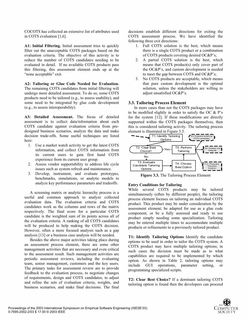
3.3. Tailoring Process Element In more cases than not the COTS packages may have
to be modified slightly in order to satisfy the OC & P’s
for the system [12]. If these modifications are directly
supported within the COTS packages themselves, then
this is considered tailoring activity. The tailoring process
element is illustrated in Figure 3.3. T1: Identify Tailoring
Options
T2: Clear Best
Choice?
T4: Choose
Best Option
T5: Perform
Tailoring
No
Yes
T3: EvaluateCandidate Tailoring
Options
A 3: Evaluate remaini ng
COTS candidates
G4: Develop andIntegrate
P12: Productize,Transit ionSoluti on
Figure 3.3. The Tailoring Process Element
Entry Conditions for Tailoring
While several COTS products may be tailored
simultaneously (often by different people), the tailoring
process element focuses on tailoring an individual COTS
product. This product may be under consideration by the
assessment element; be adapted for use as a glue code
component; or be a fully assessed and ready to use
product simply needing some specialization. Tailoring
may be entered multiple times to accommodate multiple
products or refinements to a previously tailored product.
T1: Identify Tailoring Options Identify the candidate
options to be used in order to tailor the COTS system. A
COTS product may have multiple tailoring options; in
such cases the decision must be made as to what
capabilities are required to be implemented by which
option. As shown in Table 2, tailoring options may
include GUI operations, parameter setting, or
programming specialized scripts.
T2: Clear Best Choice? If a dominant tailoring COTS
tailoring option is found then the developers can proceed
Proceedings of the 2003 International Symposium on Empirical Software Engineering (ISESE’03) 0-7695-2002-2/03 $ 17.00 © 2003 IEEE
to the development of the system. If there are still
multiple tailoring options, the developers need to evaluate
them in order to select the best option.
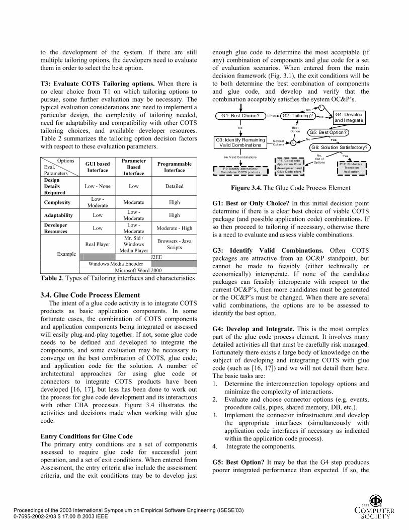
T3: Evaluate COTS Tailoring options. When there is
no clear choice from T1 on which tailoring options to
pursue, some further evaluation may be necessary. The
typical evaluation considerations are: need to implement a
particular design, the complexity of tailoring needed,
need for adaptability and compatibility with other COTS
tailoring choices, and available developer resources.
Table 2 summarizes the tailoring option decision factors
with respect to these evaluation parameters.
Options
Eval.
Parameters
GUI based
Interface
Parameter
Based
Interface
Programmable
Interface
Design
Details
Required
Low - None Low Detailed
Complexity Low -
Moderate Moderate High
Adaptability Low Low -
Moderate High
Developer
ResourcesLow
Low -
Moderate Moderate - High
Real Player
Mr. Sid /
Windows
Media Player
Browsers - Java
Scripts
J2EE
Windows Media Encoder
Example
Microsoft Word 2000
Table 2. Types of Tailoring interfaces and characteristics
3.4. Glue Code Process Element The intent of a glue code activity is to integrate COTS
products as basic application components. In some
fortunate cases, the combination of COTS components
and application components being integrated or assessed
will easily plug-and-play together. If not, some glue code
needs to be defined and developed to integrate the
components, and some evaluation may be necessary to
converge on the best combination of COTS, glue code,
and application code for the solution. A number of
architectural approaches for using glue code or
connectors to integrate COTS products have been
developed [16, 17], but less has been done to work out
the process for glue code development and its interactions
with other CBA processes. Figure 3.4 illustrates the
activities and decisions made when working with glue
code.
Entry Conditions for Glue Code
The primary entry conditions are a set of components
assessed to require glue code for successful joint
operation, and a set of exit conditions. When entered from
Assessment, the entry criteria also include the assessment
criteria, and the exit conditions may be to develop just
enough glue code to determine the most acceptable (if
any) combination of components and glue code for a set
of evaluation scenarios. When entered from the main
decision framework (Fig. 3.1), the exit conditions will be
to both determine the best combination of components
and glue code, and develop and verify that the
combination acceptably satisfies the system OC&P’s.
G1: Best Choice? G4: Develop
and Integrate
AG3: Identify Remaining
Valid Combinat ions
G2: Tailoring?Yes
No
No Val id Com binations
P2: Ident ify alternati ves:Candidates COTS products
T
SeveralOpt ions
BestOpt ion
Yes
No
Yes
G6: Solution Satisfactory?
No,Out of
Opt ionsP8: Coordi nate
Appl icat ion Code
developm ent andG lue Code effort
Yes
P12: Productize,Transit ion
Appl icat ion
No
G5: Best Option?
Figure 3.4. The Glue Code Process Element
G1: Best or Only Choice? In this initial decision point
determine if there is a clear best choice of viable COTS
package (and possible application code) combinations. If
so then proceed to tailoring if necessary, otherwise there
is a need to evaluate and assess viable combinations.
G3: Identify Valid Combinations. Often COTS
packages are attractive from an OC&P standpoint, but
cannot be made to feasibly (either technically or
economically) interoperate. If none of the candidate
packages can feasibly interoperate with respect to the
current OC&P’s, then more candidates must be generated
or the OC&P’s must be changed. When there are several
valid combinations, the options are to be assessed to
identify the best option.
G4: Develop and Integrate. This is the most complex
part of the glue code process element. It involves many
detailed activities all that must be carefully risk managed.
Fortunately there exists a large body of knowledge on the
subject of developing and integrating COTS with glue
code (such as [16, 17]) and we will not detail them here.
The basic tasks are:
1. Determine the interconnection topology options and
minimize the complexity of interactions.
2. Evaluate and choose connector options (e.g. events,
procedure calls, pipes, shared memory, DB, etc.).
3. Implement the connector infrastructure and develop
the appropriate interfaces (simultaneously with
application code interfaces if necessary as indicated
within the application code process).
4. Integrate the components.
G5: Best Option? It may be that the G4 step produces
poorer integrated performance than expected. If so, the
Proceedings of the 2003 International Symposium on Empirical Software Engineering (ISESE’03) 0-7695-2002-2/03 $ 17.00 © 2003 IEEE
G5 step determines whether one of the previously-
rejected combinations may be better.
4. Example WinWin Spiral Approach to
CBA Development
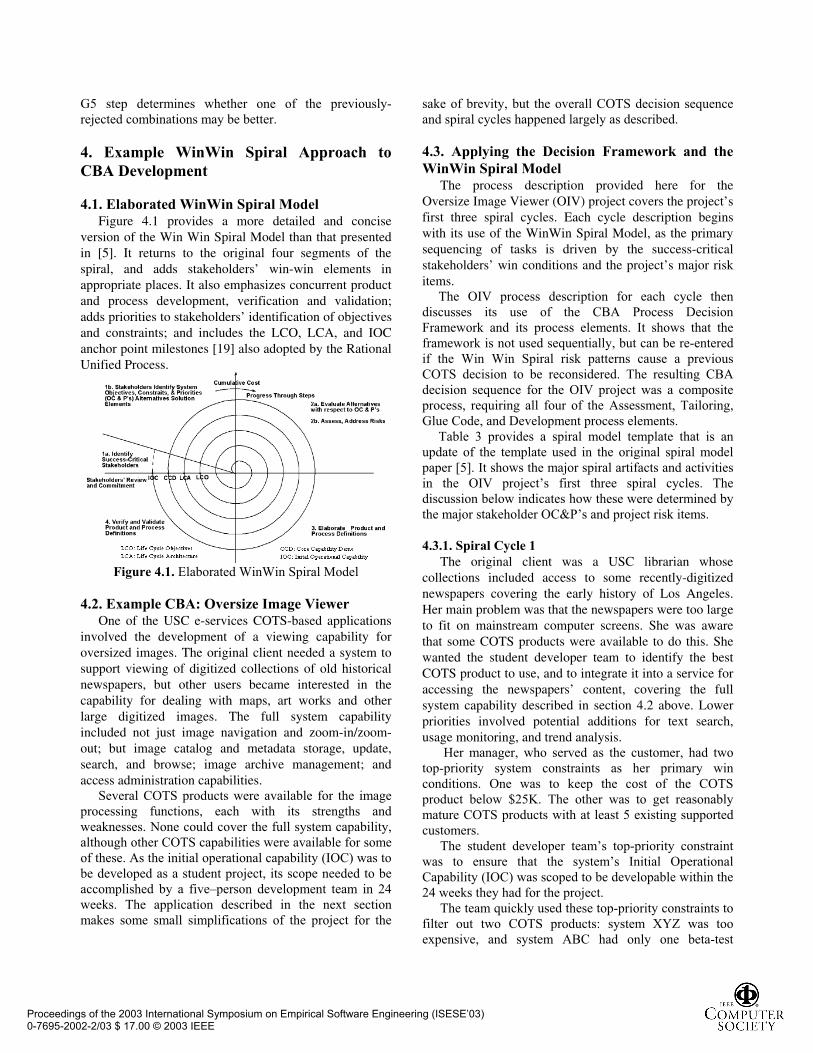
4.1. Elaborated WinWin Spiral Model Figure 4.1 provides a more detailed and concise
version of the Win Win Spiral Model than that presented in [5]. It returns to the original four segments of the spiral, and adds stakeholders’ win-win elements in appropriate places. It also emphasizes concurrent product and process development, verification and validation; adds priorities to stakeholders’ identification of objectives and constraints; and includes the LCO, LCA, and IOC anchor point milestones [19] also adopted by the Rational Unified Process.
Figure 4.1. Elaborated WinWin Spiral Model
4.2. Example CBA: Oversize Image Viewer One of the USC e-services COTS-based applications
involved the development of a viewing capability for oversized images. The original client needed a system to support viewing of digitized collections of old historical newspapers, but other users became interested in the capability for dealing with maps, art works and other large digitized images. The full system capability included not just image navigation and zoom-in/zoom-out; but image catalog and metadata storage, update, search, and browse; image archive management; and access administration capabilities.
Several COTS products were available for the image
processing functions, each with its strengths and
weaknesses. None could cover the full system capability,
although other COTS capabilities were available for some
of these. As the initial operational capability (IOC) was to
be developed as a student project, its scope needed to be
accomplished by a five–person development team in 24
weeks. The application described in the next section
makes some small simplifications of the project for the
sake of brevity, but the overall COTS decision sequence
and spiral cycles happened largely as described.
4.3. Applying the Decision Framework and the
WinWin Spiral Model The process description provided here for the
Oversize Image Viewer (OIV) project covers the project’s first three spiral cycles. Each cycle description begins with its use of the WinWin Spiral Model, as the primary sequencing of tasks is driven by the success-critical stakeholders’ win conditions and the project’s major risk items.
The OIV process description for each cycle then
discusses its use of the CBA Process Decision
Framework and its process elements. It shows that the
framework is not used sequentially, but can be re-entered
if the Win Win Spiral risk patterns cause a previous
COTS decision to be reconsidered. The resulting CBA
decision sequence for the OIV project was a composite
process, requiring all four of the Assessment, Tailoring,
Glue Code, and Development process elements.
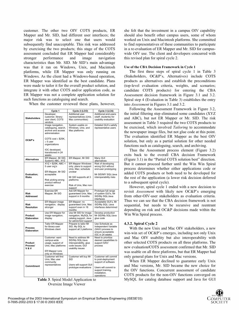
Table 3 provides a spiral model template that is an
update of the template used in the original spiral model
paper [5]. It shows the major spiral artifacts and activities
in the OIV project’s first three spiral cycles. The
discussion below indicates how these were determined by
the major stakeholder OC&P’s and project risk items.
4.3.1. Spiral Cycle 1
The original client was a USC librarian whose collections included access to some recently-digitized newspapers covering the early history of Los Angeles. Her main problem was that the newspapers were too large to fit on mainstream computer screens. She was aware that some COTS products were available to do this. She wanted the student developer team to identify the best COTS product to use, and to integrate it into a service for accessing the newspapers’ content, covering the full system capability described in section 4.2 above. Lower priorities involved potential additions for text search, usage monitoring, and trend analysis.
Her manager, who served as the customer, had two
top-priority system constraints as her primary win
conditions. One was to keep the cost of the COTS
product below $25K. The other was to get reasonably
mature COTS products with at least 5 existing supported
customers.
The student developer team’s top-priority constraint
was to ensure that the system’s Initial Operational
Capability (IOC) was scoped to be developable within the
24 weeks they had for the project.
The team quickly used these top-priority constraints to
filter out two COTS products: system XYZ was too
expensive, and system ABC had only one beta-test
Proceedings of the 2003 International Symposium on Empirical Software Engineering (ISESE’03) 0-7695-2002-2/03 $ 17.00 © 2003 IEEE
customer. The other two OIV COTS products, ER
Mapper and Mr. SID, had different user interfaces; the
major risk was to select one that users would
subsequently find unacceptable. This risk was addressed
by exercising the two products; this stage of the COTS
assessment concluded that ER Mapper had considerably
stronger performance and image navigation
characteristics than Mr. SID. Mr SID’s main advantage
was that it ran on Windows, Unix, and Macintosh
platforms, while ER Mapper was only running on
Windows. As the client had a Windows-based operation,
ER Mapper was identified as the best candidate. Plans
were made to tailor it for the overall product solution, and
integrate it with other COTS and/or application code, as
ER Mapper was not a complete application solution for
such functions as cataloguing and search.
When the customer reviewed these plans, however,
she felt that the investment in a campus OIV capability
should also benefit other campus users, some of whom
worked on Unix and Macintosh platforms. She committed
to find representatives of these communities to participate
in a re-evaluation of ER Mapper and Mr. SID for campus-
wide OIV use. The client and developers concurred with
this revised plan for spiral cycle 2.
Use of the CBA Decision Framework in Cycle 1
The first three steps of spiral cycle 1 in Table 3 (Stakeholders, OC&P’s, Alternatives) include COTS products as alternatives and establish the preconditions (top-level evaluation criteria, weights, and scenarios; candidate COTS products) for entering the CBA Assessment decision framework in Figure 3.1 and 3.2. Spiral step 4 (Evaluation in Table 3) establishes the entry into Assessment in Figures 3.1 and 3.2.
Following the Assessment Framework in Figure 3.2,
the initial filtering step eliminated some candidates (XYZ
and ABC), but not ER Mapper or Mr. SID. The risk
assessment in Table 3 required the two COTS products to
be exercised, which involved Tailoring to accommodate
the newspaper image files, but not glue code at this point.
The evaluation identified ER Mapper as the best OIV
solution, but only as a partial solution for other needed
functions such as cataloguing, search, and archiving.
Thus the Assessment process element (Figure 3.2)
exits back to the overall CBA decision Framework
(Figure 3.1) in the “Partial COTS solution best” direction.
But it cannot proceed further until the Win Win Spiral
process determines whether either applications code or
added COTS products or both need to be developed for
the rest of the application (a lower risk decision deferred
to a subsequent spiral cycle).
However, spiral cycle 1 ended with a new decision to
revisit Assessment with likely new OC&P’s emerging
from other-OIV-user stakeholders as evaluation criteria.
Thus we can see that the CBA decision framework is not
sequential, but needs to be recursive and reentrant
depending on risk and OC&P decisions made within the
Win Win Spiral process.
4.3.2. Spiral Cycle 2
With the new Unix and Mac OIV stakeholders, a new win-win set of OC&P’s emerges, including not only Unix and Mac OIV usability but also interoperability with other selected COTS products on all three platforms. The new evaluation/COTS assessment confirmed that Mr. SID was usable on all three platforms, but that ER Mapper had only general plans for Unix and Mac versions.
When ER Mapper declined to guarantee early Unix
and Mac versions, Mr. SID became the new choice for
the OIV functions. Concurrent assessment of candidate
COTS products for the non-OIV functions converged on
MySQL for catalog database support and Java for GUI
Cycle 1 Cycle 2 (LCO) Cycle 3 (LCA)
Stakeholders
Developer, customer, library-user client, COTS vendors
Additional user representatives (Unix, Mac communities)
Additional end-users (staff, students) for usability evaluation
OC&P’s
Image navigation, cataloguing, search, archive and access administration
COTS cost $25K, 5 user
organizations
IOC developed, transitioned in 24 weeks
System usable on Windows, Unix, and Mac platforms
Detailed GUI’s satisfy representative users
Alternatives ER Mapper, Mr SID, Systems ABC, XYZ
ER Mapper, Mr SID Many GUI alternatives
Evaluation;
Risks
XYZ > $25K; ABC < 5 user org’s
ER Mapper, Mr SID acceptable
Risk picking wrong product without exercise
ER Mapper Windows-only; plans to support Unix, Mac; schedule unclear
Mr SID supports all 3 platforms
Risk of Unix, Mac non-support
Risk of developing wrong GUI without end-user prototyping
Mr SID/MY SQL/Java interoperability risks
Risk
Addressed
Exercise ER Mapper, Mr SID
Ask ER Mapper for guaranteed Unix, Mac support in 9 months
Prototype full range of system GUI’s, Mr SID/My SQL/Java interfaces
Risk
Resolution
ER Mapper image navigation, display stronger
ER Mapper: no guaranteed Unix, Mac support even in 18 months
Acceptable GUI’s, Mr SID/My SQL/.Java interfaces determined
Product
Elaboration
Use ER Mapper for image navigation, display
Use Mr SID for image navigation, MySQL for catalog support, Java for admin/GUI support
Develop production Mr SID/My SQL/Java glue code
Process
Elaboration
Tailor ER Mapper for library-user Windows client
Prepare to tailor Mr SID, My SQL to support all 3 platforms
Use Schedule as Independent Variable (SAIV) process to ensure acceptable IOC in 24 weeks
Product
Process’
V & V
Customer: want campus-wide usage, support of Unix, Mac platforms
ER Mapper runs only on Windows
Need to address Mr SID/My SQL/Java interoperability, glue code issues; GUI usability issues
Need to prioritize desired capabilities to support SAIV process
Commitment
Customer will find Unix, Mac user community representatives
Customer will buy Mr SID
Users will support GUI prototype evaluations
Customer will commit to post-deployment support of software
Users will commit to support training, installation, operations
Table 3. Spiral Model Application to
Oversize Image Viewer
Proceedings of the 2003 International Symposium on Empirical Software Engineering (ISESE’03) 0-7695-2002-2/03 $ 17.00 © 2003 IEEE
support. Although the initial evaluation indicated that
these were interoperable with Mr. SID, a fully
interoperable build-upon (vs. throwaway) prototype was
scheduled to be developed and interoperability-verified in
spiral cycle 3. The other outstanding risk identified was
that the system’s GUI needed prototyping with additional
end-user representatives also planned for spiral cycle 3.
Spiral cycle 2 ended with a WinWin Spiral LCO (Life
Cycle Objectives) milestone review. At the LCO review,
all of the stakeholders agreed to support the commitments
allocated to them in the plans.
Use of the CBA Decision Framework in Cycle 2
The new stakeholders and OC&P’s in cycle 2 required the project to backtrack to the beginning of the Assessment process element in Figure 3.1 and 3.2. For the OIV function, ER Mapper was filtered out without further evaluation when it declined to guarantee early Unix and Mac versions. Some tailoring was required to verify that Mr. SID performed satisfactorily on Unix and Mac platforms.
Concurrently, Assessment filtering and evaluation
tasks were being performed for the cataloguing and GUI
functions.
This concurrency is a necessary attribute of most
current and future CBA processes. Simple deterministic
process representations are simply inadequate to address
the dynamism, time-criticality, and varying
risk/opportunity patterns of such CBA’s. However, the
Win Win spiral process provides a workable framework
for dealing with risk-driven concurrency, and the
composable CBA decision framework and process
elements provide workable approaches for handling the
associated CBA activities. The dynamism and
concurrency makes it clear that the CBA process elements
need to be recursive and reentrant, but they provide a
much-needed structure for managing the associated
complexity.
4.3.2. Spiral Cycle 3
The additional end-user stakeholder communities
increased the risk of developing GUI’s that were fine for
some users and unsatisfactory to others. These risks were
resolved by involving representative end users in
exercising GUI prototypes for various cataloguing,
search, and navigation functions. The major CBA
processes involved the Assessment of detailed
interoperability characteristics of Mr. SID, MySQL, and
the GUI software on the Windows, Unix, and Mac
platforms. This involved invocation of both the Tailoring
and Glue Code process elements.
The other major risk was the fixed 24-week IOC
development schedule. This was handled via the
Schedule as Independent Variable (SAIV) process
described in [18]. The SAIV process requires customers
and users to prioritize their desired capabilities. The
priorities are used to define a core capability clearly
buildable within the fixed schedule, and to architect the
application for ease of adding or dropping borderline-
priority features. This approach was satisfactory to the
stakeholders, and resulted in a successfully transitioned
Initial Operational Capability at the end of the 24 weeks.
Use of the CBA Decision Framework in Cycle 3
The Assessment process for interoperability of Mr
SID, My SQL, and the Java GUI components on the
Windows, Unix, and Mac platforms did not involve a
comparative evaluation of alternative COTS products,
although alternatives would have been necessary in case
one of the COTS products had proved completely
inadequate. The interoperability assessment involved
both tailoring of the COTS products for the three
platforms and some glue code to (successfully) enable
interoperability.
Subsequent spiral cycles to develop the core capability
and the IOC did not involve further Assessment, but
involved concurrent use of the Tailoring, Glue Code, and
custom development processes.
4.4. Summary of CBA Decision Framework Use The use of the CBA decision framework during the
three spiral system definition cycles and the subsequent
development activity can be summarized by the sequence
A, T; (AA); A, (TG); (TGC). The first spiral cycle
involved Assessment supported by Tailoring. The second
cycle involved two concurrent pure Assessments for the
OIV COTS choice and for the other COTS choices. The
third cycle involved an interoperability Assessment
supported by concurrent Tailoring and Glue Code
processes. The final development activity involved
concurrent Tailoring, Glue Code, and custom
development processes.
5. Conclusions The fraction of projects that are COTS-based
applications (CBA’s with over 30% of end-user
functionality provided by COTS and over 10% of
development effort devoted to COTS considerations) is
rapidly increasing in many application sectors. A 5-year
longitudinal analysis of similar small e-services
applications showed a growth from 28% CBA’s in 1997
to 60% in 2001.
For samples of both small and large CBA’s we have
analyzed, most COTS-specific effort was devoted to
COTS Assessment (A), Tailoring (T), or Glue code (G)
activities. There is no one-size-fits-all distribution of A,
T, and G effort, although there are some common patterns
and significant correlations (e.g., a -.92 negative
correlation between amount of Tailoring effort and Glue
code effort).
Proceedings of the 2003 International Symposium on Empirical Software Engineering (ISESE’03) 0-7695-2002-2/03 $ 17.00 © 2003 IEEE
Not only waterfall processes, but also standard object-
oriented, UML-based processes have significant
difficulties in dealing with the uncontrollable COTS
architecture constraints, COTS dynamism, COTS
uncertainty, and concurrency of activities involved in
developing CBA’s.
Our CBA project analysis found that for the most
part, “where the effort happens, there the process
happens.” We also found that the Assessment, Tailoring,
and Glue code activities followed similar processes for
these elements. These A, T, and G process elements, and
a custom application-code construction process element
(C), could be composed into an overall process decision
framework for CBA’s.
However, there was also no one-size-fits-all path
through the decision framework. In fact, most CBA
processes we have analyzed are dynamic and concurrent,
and the process elements need to be reentrant and
recursive.
Using the WinWin Spiral Model’s risk-driven
approach coupled with the CBA decision framework as a
process model generator, however, enabled projects to
generate appropriate combinations of A, T, G, and C
process elements that best fit their project situation and
dynamics. An extensive discussion of its application to an
actual CBA project is provided as an example.
The resulting combinations of A,T,G, and C elements
serve as a sort of genetic code for the projects CBA
process which can be used to identify and compare it with
other projects CBA processes. The analogy can be
stretched too far, but it suggests several attractive
directions for future research, such as determining how
best to represent the concurrency and backtracking
aspects; validating and refining effort distributions based
on process elements; assessing the validity of the process
elements and decision framework in other CBA sectors;
and identifying common process element configurations,
valid and invalid configurations, or large-grain CBA
process patterns.
6. Acknowledgements This research was supported by the National Science
Foundation, by the Federal Aviation Administration, and
by the USC-CSE Affiliates. We obtained particularly
valuable insights from discussions with A. Winsor Brown
(USC-CSE), Betsy Bailey Clark and Bradford Clark
(Software Metrics), Patricia Oberndorf (SEI), Prof. David
Klappholz (Stevens Institute of Technology), and Arthur
Pyster (FAA).
7. References [1] C. Abts, B. Boehm, and E. Bailey Clark, “COCOTS: A
Software COTS-Based System (CBS) Cost Model,”
Proceedings, ESCOM 2001, April 2001, pp. 1-8.
[2] C. Albert and L. Brownsword, “Evolutionary Process for
Integrating COTS-Based Systems (EPIC): An Overview,”
CMU-SEI-2002-TR-009, July 2002.
[3] R. Balzer, “Living with COTS,” Proceedings, ICSE 24, May
2002, p. 5.
[4] B. Boehm, A. Egyed, J. Kwan, D. Port, A. Shah, and R.
Madachy, “Using the WinWin Spiral Model: A Case Study,”
Computer, July 1998, pp. 33-44.
[5] B. Boehm, “A Spiral Model of Software Development and
Enhancement,” Computer, May 1988, pp. 61-72.
[6] B. Boehm, C. Abts, A.W. Brown, S. Chulani, B.K. Clark, E. Horowitz, R. Madachy, D. Reifer, and B. Steece, Software Cost
Estimation with COCOMO II, Prentice Hall, 2000. [7] L. Brownsword, P. Oberndorf, and C. Sledge, “Developing
New Processes for COTS-Based Systems,” Software,
July/August 2000, pp. 48-55.
[8] M. Morisio, C. Seaman, A. Parra, V. Basili, S. Kraft, and S.
Condon, “Investigating and Improving a COTS-Based Software
Development Process,” Proceedings, ICSE 22, June 2000, pp.
32-41.
[9] V. Basili and B. Boehm, “COTS Based System Top 10
List,” Computer, May 2001, pp 91-93.
[10] B. C. Meyers and P. Oberndorf, Managing Software
Acquisition: Open Systems and COTS Products, Addision
Wesley, 2001.
[11] G. Benguria, A. Garcia, D. Sellier, and S. Tay, “European
COTS Working Group: Analysis of the Common Problems and
Current Practices of the European COTS Users,” COTS-Based
Software Systems (Proceedings, ICCBSS 2002), Springer
Verlag, 2002, J. Dean and A. Gravel (eds.), pp. 44-53.
[12] D. Port, J. Bhuta, Y. Yang, B. Boehm, “Not All CBS Are
Created Equally: COTS Intensive Project Types,” Submitted to
ICCBSS 2002.
[13] C. Ncube and J. Dean, “The Limitations of Current
Decision-Making Techniques in the Procurement of COTS
Software Components,” COTS – Based Software Systems J.
Dean and A. Gravel (eds.), Springer Verlag, 2002, RP-176-187.
[14]. N. Maiden, H.Kim, and C. Ncube, “Rethinking Process
Guidance for Selecting Software Components,” COTS-Based
Software Systems, J.Dean and A.Gravel (eds.), Springer Verlag,
2002, pp.151-164.
[15] S.Comella- Dorda, J.Dean, E.Morris, and P.Oberndorf, “A
Process for COTS Software Product Evaluation,” COTS -Based
Software Systems , J.Dean and A.Gravel (eds.), Springer
Verlag,2002, pg. 86-96
[16]. N. Medvidovic, R. Gamble, and D. Rosenblum, “Towards
Software Multioperability: Bridging Heterogeneous Software
Interoperability Platforms,” Proceedings, Fourth International
Software Architecture Workshop, 2000
[17] L.Davis and R. Gamble, “Identifying Evolvability for
Integration,” COTS-Based Software Systems, J.Dean and A.
Gravel (eds.) Springer Verlag, 2002, pp.65-75
[18] B.Boehm, D. Port, L. Huang and W. Brown, “Using the
Spiral Model and MBASE to Generate New Acquisition Process
Models: SAIV, CAIV, and SCQAIV,” Cross Talk, January
2002, pp.20-25 (http://www.stsc.hill.af.mil/crosstalk)
[19] B. Boehm, “Anchoring the Software Process,” Software,
July 1996, pp. 73-82
Proceedings of the 2003 International Symposium on Empirical Software Engineering (ISESE’03) 0-7695-2002-2/03 $ 17.00 © 2003 IEEE
Related Documents