1 Verilog HDL /29 Components of a Verilog Module behavioral modeling

Components of a Verilog Module
Jan 01, 2016
behavioral modeling. Components of a Verilog Module. behavioral modeling. Review. They will produce the same logical model and functionality. behavioral modeling. Always/Initial Blocks. behavioral modeling. Procedural Assignments. Blocking Assignment ( = ) - PowerPoint PPT Presentation
Welcome message from author
This document is posted to help you gain knowledge. Please leave a comment to let me know what you think about it! Share it to your friends and learn new things together.
Transcript

1Verilog HDL /29
Components of a Verilog Modulebehavioral modeling
2Verilog HDL /29
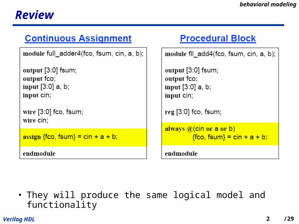
Review
• They will produce the same logical model and functionality
behavioral modeling
3Verilog HDL /29
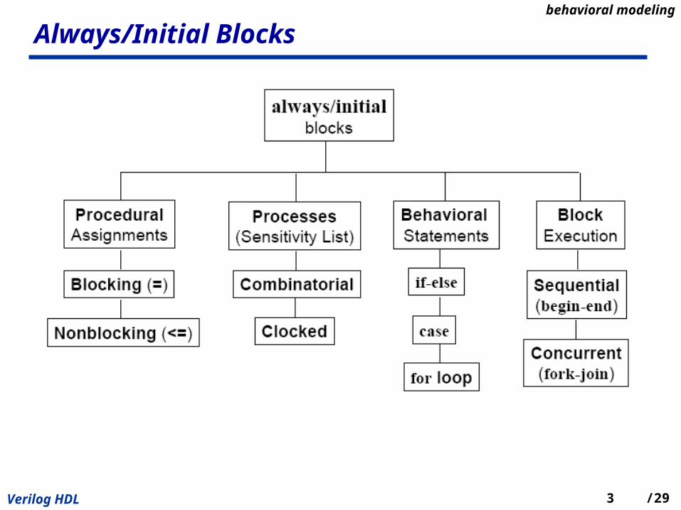
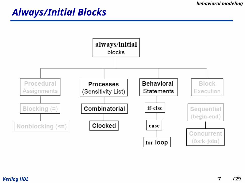
Always/Initial Blocksbehavioral modeling

4Verilog HDL /29
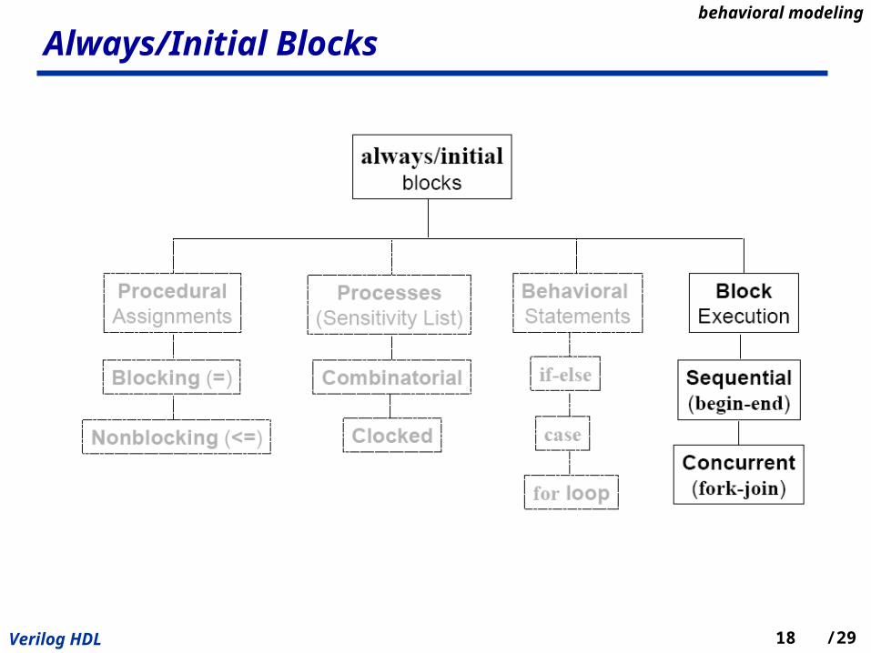
Procedural Assignments
• Blocking Assignment (=)
– Executed in the order they are specified in a sequential block
• Nonblocking Assignment (<=)
– Allow scheduling of assignments without blocking execution of the state
ments that follow in a sequential block
– Recommended: Use Nonblocking assignments for clocked processes w
hen writing synthesizable code.
behavioral modeling
5Verilog HDL /29
Procedural Assignments (2)
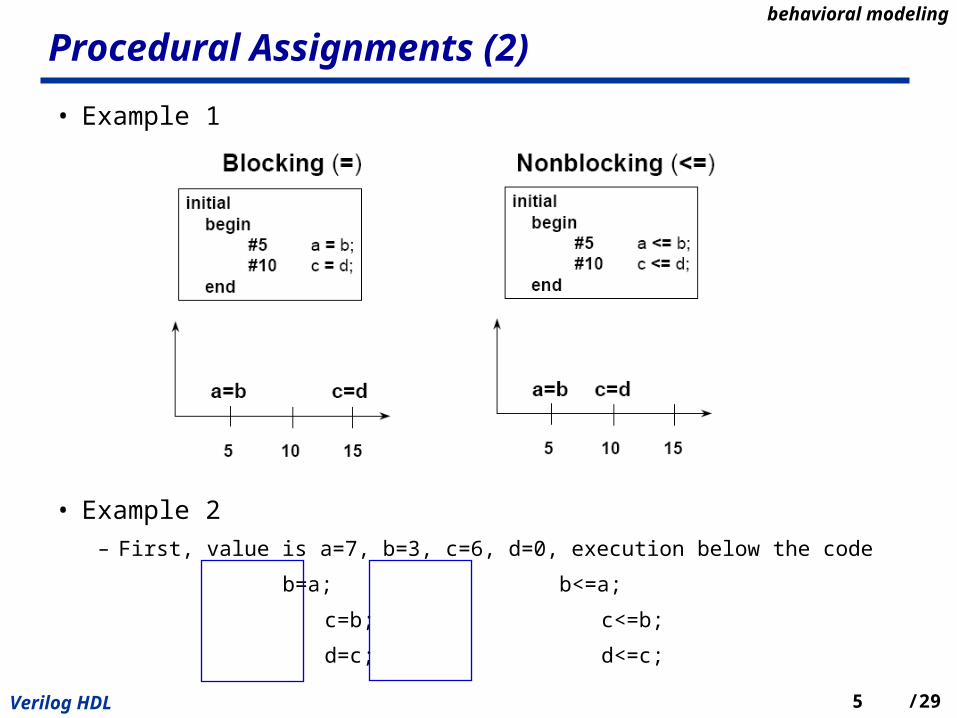
• Example 1
• Example 2
– First, value is a=7, b=3, c=6, d=0, execution below the code
b=a; b<=a;
c=b; c<=b;
d=c; d<=c;
behavioral modeling
6Verilog HDL /29
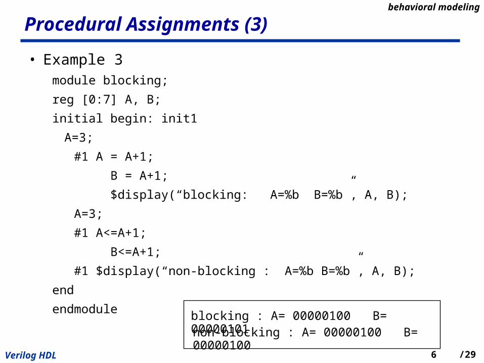
Procedural Assignments (3)
• Example 3module blocking;
reg [0:7] A, B;
initial begin: init1
A=3;
#1 A = A+1;
B = A+1;
$display(“blocking: A=%b B=%b”, A, B);
A=3;
#1 A<=A+1;
B<=A+1;
#1 $display(“non-blocking : A=%b B=%b”, A, B);
end
endmoduleblocking : A= 00000100 B= 00000101non-blocking : A= 00000100 B= 00000100
behavioral modeling
7Verilog HDL /29
Always/Initial Blocksbehavioral modeling

8Verilog HDL /29
Sensitivity List
• Sensitivity List:
– This procedural block (process) executes after a change in any signal in the Sensitivity List
behavioral modeling

9Verilog HDL /29
Two Types of Processes
• Combinatorial process
– Sensitive to all inputs used in the combinatorial logic
– Example
» always @(a or b or sel)
» sensitivity list includes all inputs used in the combinatorial logic
• Clocked process– Sensitive to a clock or/and control signals
– Example
» always @(posedge clk or negedge clr)
» sensitivity list does not include the d input, only the clock or/and control signals
behavioral modeling

10Verilog HDL /29
Behavioral Statements
• Behavioral statements
– IF-ELSE statement
– CASE statement
– Loop statement
• These behavioral statements can also be used in a clocked process
behavioral modeling
11Verilog HDL /29
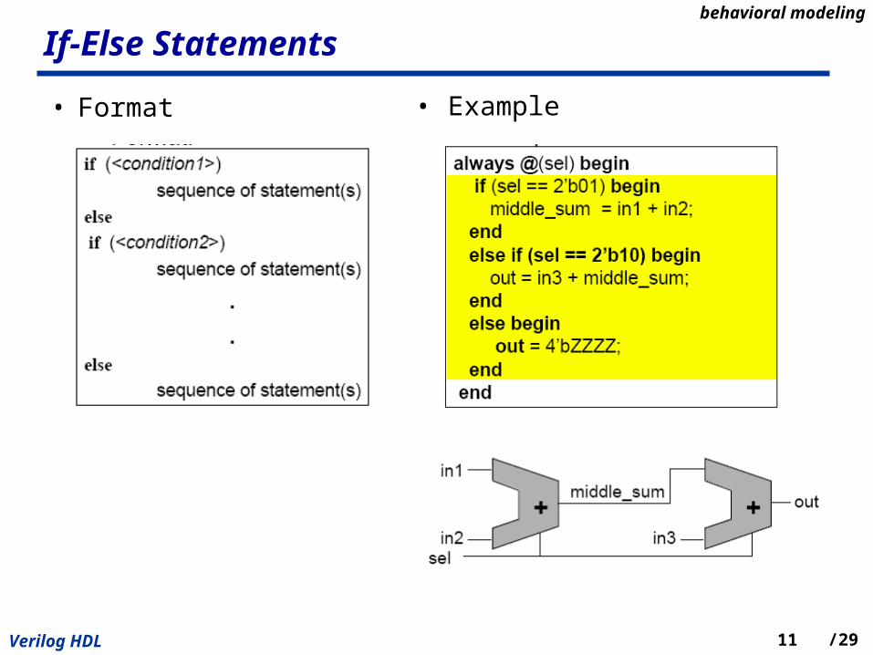
If-Else Statements
• Format • Example
behavioral modeling

12Verilog HDL /29
If-Else Statements (2)
• Conditions are evaluated in order from top to bottom
– Prioritization
• The first condition, that is true, causes the corresponding seque
nce of statements to be executed.
• If all conditions are false, then the sequence of statements asso
ciated with the “else” clause is evaluated.
behavioral modeling
13Verilog HDL /29
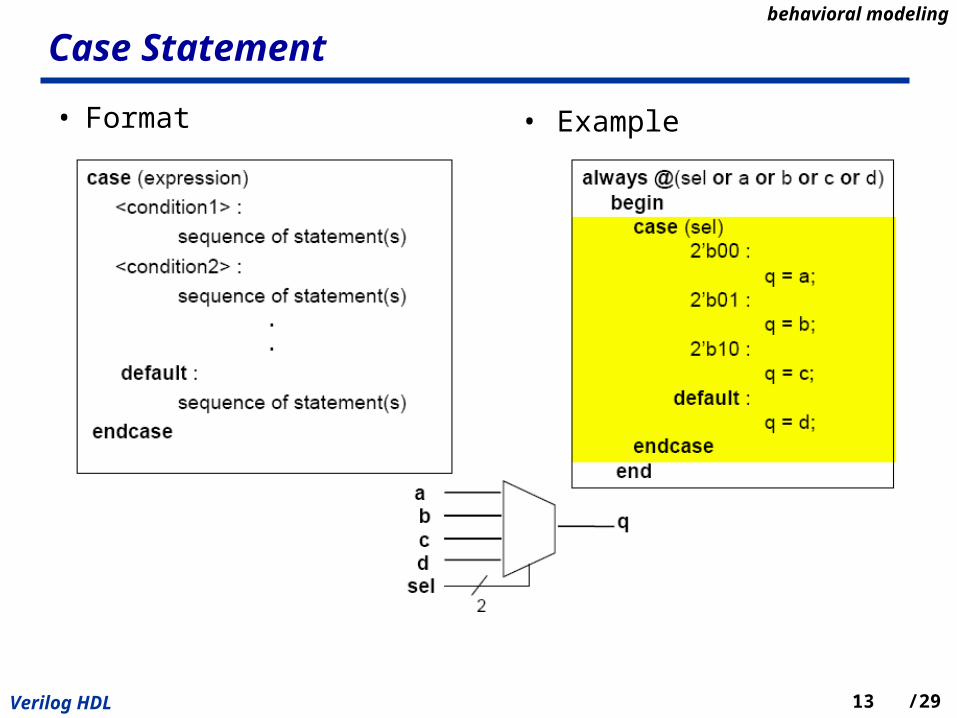
Case Statement
• Format
• Example
behavioral modeling

14Verilog HDL /29
Case Statement (2)
• Conditions are evaluated at once
– No prioritization
• All possible conditions must be considered
• default clause evaluates all other possible conditions that are
not specifically stated
behavioral modeling

15Verilog HDL /29
Loop Statements
• forever loop – executes continually
• repeat loop – executes a fixed number of times
behavioral modeling

16Verilog HDL /29
Loop Statements (2)
• while loop – executes if expression is true
behavioral modeling
17Verilog HDL /29
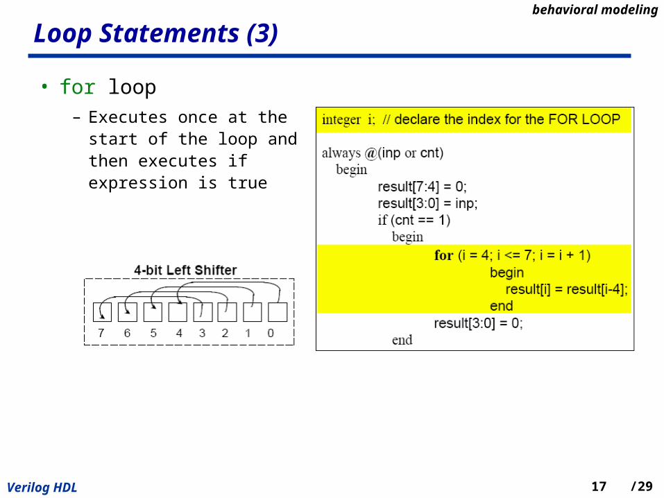
Loop Statements (3)
• for loop– Executes once at the start of
the loop and then executes if expression is true
behavioral modeling
18Verilog HDL /29
Always/Initial Blocksbehavioral modeling

19Verilog HDL /29
Two Types of Block Executions
• Sequential Blocks
– Statements between begin and end execute sequentially
– If there are multiple behavioral statements inside an initial and always block and you want the statements to execute sequentially, the statements must be grouped using the keywords begin and end.
• Parallel Blocks – Statements between fork and join ex
ecute in parallel
– If there are multiple behavioral statements inside an initial and always block and you want the statements to execute in parallel, the statements must be grouped using the keywords fork and join
fork: three begin // code for thread1 end begin // code for thread2 end begin // code for thread3 endjoin // merge the threads to one
behavioral modeling

20Verilog HDL /29
Sequential vs. Parallel Blocks
• Sequential and parallel blocks ca be nested
behavioral modeling

21Verilog HDL /29
Components of a Verilog Modulebehavioral modeling
22Verilog HDL /29
Verilog Functions and Tasks
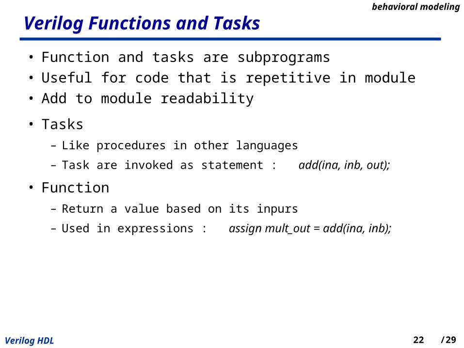
• Function and tasks are subprograms
• Useful for code that is repetitive in module
• Add to module readability
• Tasks– Like procedures in other languages
– Task are invoked as statement : add(ina, inb, out);
• Function– Return a value based on its inpurs
– Used in expressions : assign mult_out = add(ina, inb);
behavioral modeling

23Verilog HDL /29
Differences
• Functions
– Can enable another function but not another task
– Always executes in zero simulation time
– Can not contain any delay, event, or timing control statements
– Must have at least one input argument
– Always return a single value
– Can not have output or inout arguments
• Tasks
– Can enable other tasks and functions
– May execute in non-zero simulation time
– May contain delay(#), event(@), or timing control statements (wait)
– May have zero or more input, output or inout arguments
– Do not return a value
behavioral modeling
24Verilog HDL /29
Task
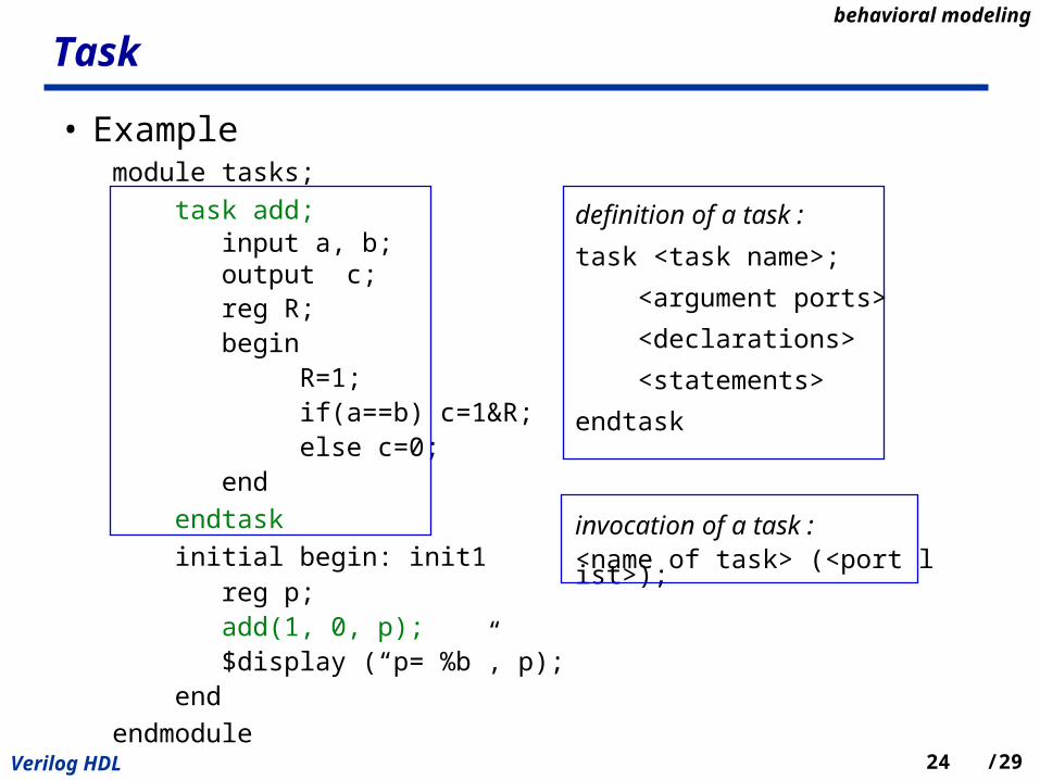
• Examplemodule tasks;
task add; input a, b; output c; reg R; begin R=1; if(a==b) c=1&R; else c=0; end
endtask
initial begin: init1 reg p; add(1, 0, p); $display (“p= %b”, p); end
endmodule
definition of a task :
task <task name>;
<argument ports>
<declarations>
<statements>
endtask
invocation of a task :<name of task> (<port list>);
behavioral modeling

25Verilog HDL /29
Function
• Examplemodule functions;
function [1:1] add2; input a, b;
reg R;
begin
R=1;
if(a==b) c=1&R;
else c=0;
end
endfunction
initial begin: init1
reg p;
p = add2(1,0);
$display (“p= %b”, p);
end
endmodule
definition of a function :
task <range or type><function name>;
<argument ports>
<declarations>
<statements>
endtask
invocation of a function :value = <name of function> (<port list>);
behavioral modeling
26Verilog HDL /29
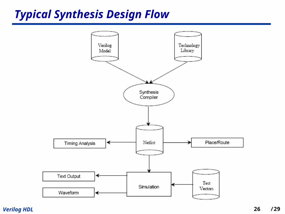
Typical Synthesis Design Flow

27Verilog HDL /29
T Flip-Flop Example

28Verilog HDL /29
T Flip-Flop Example (2)

29Verilog HDL /29
Homework
• 4-bit UP Counter
– Use ISE and ModelSim (refer “ISE Quick Start Tutorial”)
– Design 4-bit up counter
– Create a test bench waveform in HDL bencher
– Simulating with ModelSim
Related Documents


![“A Verilog OverviewA Verilog Overview”hernande/Eng312/TCNJ_Verilog(R)_V...Comparator Verilog Source Code // Eight-bit Comparator module compare (A, B, EQ) input [7:0] A, B; output](https://static.cupdf.com/doc/110x72/5f8b8feb76f68678470c12e5/aoea-verilog-overviewa-verilog-overviewa-hernandeeng312tcnjverilogrv.jpg)
