Component-based application development using a Mixed-Language Programming (MLP) approach By Murali Krishnan Gunasekaran Thesis submitted to the Faculty of the Virginia Polytechnic Institute and State University in partial fulfillment of the requirements for the degree of Master of Science in Computer Science and Applications Dr. Wayne Neu, Co-Chair Dr. Calvin Ribbens, Co-Chair Dr. Alan Brown Dr. Cliff Shaffer December, 2003 Blacksburg, Virginia Keywords: Mixed-language programming, Cross-language programming, Component software, ModelCenter, Analysis Server, ASSET, ship design software

Welcome message from author
This document is posted to help you gain knowledge. Please leave a comment to let me know what you think about it! Share it to your friends and learn new things together.
Transcript
Component-based application development using a Mixed-Language Programming (MLP) approach
By
Murali Krishnan Gunasekaran
Thesis submitted to the Faculty of the
Virginia Polytechnic Institute and State University
in partial fulfillment of the requirements for the degree of
Master of Science
in
Computer Science and Applications
Dr. Wayne Neu, Co-Chair Dr. Calvin Ribbens, Co-Chair
Dr. Alan Brown Dr. Cliff Shaffer
December, 2003 Blacksburg, Virginia
Keywords: Mixed-language programming, Cross-language programming, Component software, ModelCenter, Analysis Server, ASSET, ship design software
Component-based application development using a Mixed-Language Programming (MLP) approach
By
Murali Krishnan Gunasekaran
ABSTRACT
Component-based software construction has gained a large momentum and become a
main focus of software engineering research and computing. Even though there are many
standards available now for developing component-based applications, there are still
applications where a single-language based approach is not suitable. Some of the actions
that a program performs are best expressed in a particular language, and the choice of a
programming language is strongly dictated by the programmer’s preference. This thesis
investigates how a Mixed-Language Programming (MLP) approach can be used to build
component-based software systems, with a specific emphasis on a ship design problem.
This approach is also compared with a newer tool-based integration methodology of
modeling and building component-based software applications, using tools such as
Phoenix Integration Inc.’s ModelCenter and Analysis Server. This method is used to
solve the same ship design problem using ModelCenter and a ship design software called
Advanced Surface Ship Evaluation Tool (ASSET).
Acknowledgements
I would like to thank Dr. Wayne Neu and Dr. Alan Brown of the Aerospace & Ocean
Engineering department for giving me the opportunity to work on this project. Their
unwavering support and confidence in my abilities were the primary motivating factors
for me. I would also like to thank Dr. Calvin Ribbens of the Computer Science
department for agreeing to act as my Co-Advisor and for his valuable comments and
suggestions, Dr. Clifford Shaffer for acting as my committee member, Sandipan Ganguly
for helping me with the design and programming of some of the modules.
And, last but not the least, I would like to extend my gratitude and thanks to the people
who mean the most to me, my parents. Without their constant support and encouraging
words, none of this would have been possible.
Table Of Contents
1. INTRODUCTION............................................................................................................................... 7 PROBLEM STATEMENT ............................................................................................................................... 7 RESEARCH GOALS AND CONTRIBUTIONS..................................................................................................... 7 SCOPE......................................................................................................................................................... 8 OVERVIEW OF THESIS ................................................................................................................................. 8 RELATED WORK......................................................................................................................................... 9
Babel ..................................................................................................................................................... 9 Common-Component Architecture...................................................................................................... 10 TOOLBUS........................................................................................................................................... 12 C programming in CADES environment............................................................................................. 12
2. COMPONENT SOFTWARE .......................................................................................................... 14 WHAT IS A COMPONENT?.......................................................................................................................... 14 COMPONENT-BASED SOFTWARE PROCESS MODEL: ................................................................................... 14
Component Qualification: .................................................................................................................. 15 Component Adaptation and/or composition: ...................................................................................... 15
NEED FOR A COMPONENT-BASED DEVELOPMENT APPROACH: .................................................................. 16 DIFFERENT STANDARDS FOR COMPONENT SOFTWARE: ............................................................................ 19
CORBA: .............................................................................................................................................. 19 COM: .................................................................................................................................................. 20
Benefits of COM:............................................................................................................................................ 21 JavaBeans:.......................................................................................................................................... 24
3. MIXED LANGUAGE PROGRAMMING (MLP):........................................................................ 26 SINGLE-LANGUAGE APPROACH VS. MIXED-LANGUAGE PROGRAMMING APPROACH:................................. 26 WHAT IS MIXED LANGUAGE PROGRAMMING (MLP)?.............................................................................. 26 RATIONALE FOR MLP: ............................................................................................................................. 27 WHEN TO USE MLP:................................................................................................................................. 27 MIXED LANGUAGE PROGRAMMING APPROACHES:................................................................................... 28
Traditional approach:......................................................................................................................... 28 Key differences between the languages: ............................................................................................. 33
Data types: ...................................................................................................................................................... 33 Arrays: ............................................................................................................................................................ 33 Characters and Strings: ................................................................................................................................... 34 User-defined data types:.................................................................................................................................. 34
MLP issues:......................................................................................................................................... 34 Calling Conventions:....................................................................................................................................... 36 Naming conventions: ...................................................................................................................................... 36 Passing parameters:......................................................................................................................................... 38
CONCEPT OF DYNAMIC LINKED LIBRARIES (DLLS):................................................................................ 40 EXAMPLES OF MLP:................................................................................................................................. 41
C calling FORTRAN routine: ............................................................................................................. 42 FORTRAN calling a C routine: .......................................................................................................... 43
4. CASE STUDY I: MOGO ................................................................................................................. 45 INTRODUCTION TO MULTI-OBJECTIVE GENETIC OPTIMIZATION (MOGO): .............................................. 45
What is Optimization: ......................................................................................................................... 45 Difference between Single and Multiple objective optimization:........................................................ 46 Multi-objective Genetic Algorithm based optimization: ..................................................................... 48 MOGO for ship design problem.......................................................................................................... 49 MOGO program – ship analysis part and GA .................................................................................... 50
Function of the Ship Analysis Component:..................................................................................................... 50 Function of the GA: ........................................................................................................................................ 51
COM ARCHITECTURE: ............................................................................................................................. 52 DRAWBACKS OF THE ABOVE MLP APPROACH:......................................................................................... 55
5. CASE STUDY II: MODELCENTER-ASSET ............................................................................... 57 WHAT IS MODELCENTER?........................................................................................................................ 57 ASSET – SHIP DESIGN AND ANALYSIS PROGRAM:................................................................................... 60
Basic System Architecture: ................................................................................................................. 61 WRAPPING ASSET MODULES AS SCRIPT COMPONENTS:.......................................................................... 61
Steps to create a Script Component:................................................................................................... 62 VBScript code to interact with ASSET ................................................................................................ 62 Assembly components: ........................................................................................................................ 64 Driver component: .............................................................................................................................. 65
Testing for convergence:................................................................................................................................. 65 Optimizer component .......................................................................................................................... 66
ADVANTAGES OF THE TOOL-BASED INTEGRATION APPROACH:................................................................. 67 DISADVANTAGES OF USING A TOOL-BASED INTEGRATION APPROACH: ..................................................... 69 CONCLUSION ............................................................................................................................................ 71 FUTURE WORK:......................................................................................................................................... 72 REFERENCES: ........................................................................................................................................... 73

List of figures:
Figure 2-1 Model-View Controller Architecture.............................................................. 18 Figure 2-3 COM Object diagram...................................................................................... 20 Figure 2-4 Client-Server relationships.............................................................................. 21 Figure 2-5 In-process relationship .................................................................................... 22 Figure 2-6 Out-of-Process local client/server relationship ............................................... 23 Figure 3-1 Output of C calling Fortran ............................................................................. 43 Figure 3-2 Output of FORTRAN calling C ..................................................................... 44 Figure 4-1 Schematic of an ideal multi-objective optimization procedure....................... 47 Figure 4-2 Schematic of the Preference-based multi-objective optimization procedure.. 48 Figure 4-3 COM architecture of MOGO .......................................................................... 52 Figure 4-4 MOGO User Interface..................................................................................... 53 Figure 4-5 Pareto plot of non-dominated frontier ship designs ........................................ 54 Figure 4-6 Shuttle Tanker non-dominated frontier ship designs ...................................... 55 Figure 5-1 ModelCenter User Interface............................................................................ 58 Figure 5-2 ModelCenter-Analysis Server......................................................................... 59 Figure 5-3 Server browser in ModelCenter ...................................................................... 59 Figure 5-4 ModelCenter-ASSET interaction.................................................................... 61 Figure 5-5 ModelCenter Script Component ..................................................................... 61 Figure 5-6 Script Component Editor with a simple script ................................................ 62 Figure 5-7 ModelCenter-ASSET interaction using Script Components........................... 63 Figure 5-8 Assembly components .................................................................................... 64 Figure 5-9 Design variables in a component within the Assembly component ............... 65 Figure 5-10 Driver component schematic......................................................................... 65 Figure 5-11 Driver component to check for convergence ................................................ 66
List of tables:
Table 3-1 Datatypes in FORTRAN, C/C++ and Visual Basic ......................................... 35 Table 3-2 C and FORTRAN Calling conventions [MS] .................................................. 36 Table 3-3 Naming conventions in FORTRAN, C and C++ ............................................. 37 Table 3-4 Default parameter passing conventions in C, C++ and FORTRAN ................ 39 Table 5-1 Functionality of wrapping tools in ModelCenter ............................................. 68
Chapter 1
1. Introduction
Problem Statement Component based software systems are seen as the holy grail of software applications.
There is a lot of benefit in creating component based software systems, since they offer a
lot of flexibility and adaptability that monolithic software systems do not. There are
different approaches to developing components and component-systems. A mixed-
language approach is sometimes very favorable since it allows existing components
developed in different languages to be combined into bigger systems. It is especially
helpful in building scientific applications since existing libraries (developed in different
programming languages such as C, C++, FORTRAN etc) can be used without re-writing
any new code. But, there are inherent difficulties in this approach since it usually
involves understanding and overcoming the different issues in mixing multiple
languages. We discuss another component-based approach for building and modeling
systems, that involves using a client software called ModelCenter and a server software
called Analysis Server. A multi-objective ship design problem that involves ship analysis
component and an Genetic Algorithm optimizer is built using both the approaches and
the pros and cons of each of the approaches is discussed.
Research goals and contributions The main goal of this thesis work is to analyze and develop a component-based solution
for a ship design problem using two different approaches and discuss the advantages and
disadvantages of both the approaches. The ship design problem consists of finding a
group of optimal solutions among a ship population based on the two main objectives –
total cost of ownership and overall measure of effectiveness. The first approach involves
creating a visual user interface and two separate components (dynamic linked library
files) that encapsulate the ship analysis and optimizer functionality respectively. The two
components have been created using a mixed language programming approach out of
existing FORTRAN modules. The second approach involves using the tools
ModelCenter, Analysis Server and ASSET to solve the same ship design problem. The
goal is to illustrate a newer and easier method of building component-based systems
using latest tools such as ModelCenter. Finally, a discussion on the advantages and
drawbacks of both the approaches and when to use which approach is also done to help
the reader in making a good choice when it comes to building component-based systems.
Scope This thesis encompasses the following:
• Design of a component architecture for solving the ship design problem
• Creation of a tool with a visual user interface and two separate components made
from existing FORTRAN modules
• Design of a “model” using Script Components in the ModelCenter software to
solve the same ship design problem.
• Comparison of the advantages and disadvantages of the two approaches
This thesis does not include the following:
• Integration of a multi-objective optimizer in ModelCenter
• Comparison of the output of the ModelCenter program with that of the mixed
language tool
Overview of thesis Following this section, a brief overview of related research work is discussed. Chapter 2
gives an introduction to component technology, component-based software and some of
the popular component standards. Chapter 3 discusses the mixed language programming
approach used in developing cross-language applications. Emphasis is placed on

development using C, C++ and FORTRAN, since they are commonly used. Chapter 4
discusses the Multi-objective Genetic Optimization tool developed to solve a ship design
problem using the mixed language programming approach. Chapter 5 discusses how
Script components can be written using the ModelCenter tool and the same ship design
problem is solved using ModelCenter and a ship design software called Advanced
Surface Ship Evaluation Tool or ASSET. The advantages and disadvantages of both the
approaches are also discussed in this section.
Related Work To facilitate mixed language application development in both local and distributed
systems, many approaches have been proposed. Some of them are based on the use of a
intermediate Interface Description Language (IDL), while others are not. Quarrie [7]
describes a distributed framework based on the concept of using an IDL to generate
language mappings. Some of the most pertinent and related research work are discussed
below.
Babel Bable is a software tool developed as part of the Component Technologies Project at the
Center for Applied Scientific Computing located at the Lawrence Livermore National
Laboratory. It is a tool that can be used for mixing C, C++, Fortran77, Fortran90, Python,
and Java in a single application. The main goal of the Bable project was language
interoperability, i.e., to make scientific software libraries equally accessible from all of
the standard programming languages. Language differences often force software
developers to generate “glue code” to communicate with other library of components.
Babel aids in generating this glue code for the developer in a consistent and compatible
manner.
Babel lets programmers use their tool of choice in developing complete applications
using components implemented in one or more distinct programming languages [Babel
User’s Guide]. Babel accomplishes this using a Scientific Interface Definition Language
(SIDL). SIDL is an intermediate interface definition language that is similar in nature to
the CORBA and COM IDLs, but is specifically designed for scientific applications. It has
built-in support for complex numbers and dynamic multi-dimensional arrays. SIDL is
object-oriented and its object model closely resembles that of Java and Objective C. It
does not allow multiple inheritance from classes, but single inheritance from
implementation and multiple inheritance through interfaces.
The Babel tool suite consists of a parser, a code generator, a small run-time library and
the Alexandria component repository. The SIDL parser helps in parsing a SIDL
description and generating language binding code in XML format. The goal is that the
XML code will represent the required language bindings to communicate with a
particular software library. Thus, a scientist downloading a particular component library
from the repository would also be able to use the language bindings generated by the
Babel tool.
The Babel tool represents the work which is closest to the goals of this thesis. It goes a
step further from the traditional mixed-language programming methods, in that it uses an
IDL which can be used to generate glue code that allows a software library implemented
in one supported language to be called from any other supported language. The Babel
tool is specifically meant for use with developing scientific software applications and the
goal is to alleviate the problems associated with using components developed in multiple
languages.
Common-Component Architecture The Common-Component Architecture (CCA) is a framework for building component-
based large-scale scientific applications that provides a plug-and-play style of integration
mechanism. It is especially useful for building high-performance computing applications.
The CCA acts as a container for a group of components that can interact with each other
and to the framework by means of ports. Ports are merely interfaces that are completely
separate from all implementation issues and they correspond to interfaces in Java and
abstract virtual classes in C++ [6]. The CCA ports follow a uses-provides design pattern.
Each component in the framework must declare what ports it uses from other components
and for what ports it provides an implementation. Each component has the ability to
register itself to the CCA using a Services interface and in this way the CCA framework
acts as an intermediary between component interactions. Each component is required to
implement the setServices method of the Services interface. When a particular component
needs the services of another component, it uses the getPort method of the Services
interface to obtain a reference to the port, which can then be used to invoke the methods
provided by that port. When the using component has completed its activity and no
longer needs the port, it calls releasePort to release it.
The CCA also incorporates the Babel language interoperability tool discussed earlier.
This allows scientific components developed in different programming languages to be
used together to build larger applications. The SIDL is also used to specify the CCA
interfaces. The CCA specifications do not describe implementation issues and only
describes how components can interact with each other and the framework. It also does
not specify how parallel computing should or can be done and it is left to the implementer
of the framework. The prototype Ccaffeine framework [1] provides a C++
implementation of the CCA framework, that focuses on building high-performance
parallel CCA applications.
The CCA framework is similar to the ModelCenter application in that it provides similar
degrees of functionality between components. In ModelCenter, communication between
components is achieved by means of links. Though the concept of ports is absent in
ModelCenter, the underlying functionality is the same, since the end points of the links
are variables with associated data types. The components in ModelCenter can have a
script associated with them that describes their functionality. The script can in turn
invoke other components within ModelCenter or outside of it. More information on
ModelCenter is provided in Chapter 5.
TOOLBUS The TOOLBUS is a software coordination architecture for the interconnection and
integration of components written in different languages and running on different
machines. The key idea behind this work is that building heterogeneous, large-scaled
applications usually involves integration of tools that is based on the interoperability of
software components. The TOOLBUS architecture forbids direct component
communication and all interactions between components are controlled by “scripts” that
define the interaction among the tools (components). This leads to a communication
architecture that resembles a hardware communication bus and hence its called a
TOOLBUS [2]. This approach also uses the concept of Intermediate Data Description
Language (IDDL), that defines a bi-directional conversion between data structures in the
implementation languages and the common, language-independent data format. The
TOOLBUS imposes a restriction of common data representation (based on term formats)
and message protocols to facilitate communication between the different tools, and this is
achieved by having a small layer of software called an adapter for each tool. The
TOOLBUS scripts specify how data integration, control integration and user-interface
integration will be performed. The scripts support the creation of processes and
primitives and communication with tools on different systems is accomplished using
TCP/IP. More information about the TOOLBUS architecture, scripts, its applications and
the enhancements made to it can be obtained from [2], [3] and [4].
C programming in CADES environment CADES stands for Computer Aided Development and Evaluation System and the
CADES environment is one of the oldest database repositories. It was originally used to
store code written in the S3 language, but is sufficiently flexible to support many
imperative programming languages with little change. The entities in CADES are typed
and named, and have fields whose values are strings or numbers. There are four main
objects in the schema of the CADES system and these correspond to the main elements
of an imperative language. Mode objects represent data type definitions, Data objects
represent global variable declarations, Holons represent the bodies of functions and
procedures and Holon interfaces represent the headers or signatures of the procedures or
functions. In order to use some of the S3 language based code in the CADES system
from other languages such as C, extra fields are added to the Mode record in the CADES
database. These fields provide a mapping between the programming language type and
the abstract representation construct. The language used to describe this abstract
representation consists of constructs such as seq of, and basic types such as character,
integer etc. From these relationships, an algorithm or method is devised to convert an
instance of a type in one representation to an instance in another representation. A more
detailed description of how S3 to C language conversion can be done in the CADES
environment is given in [5].
Chapter 2
2. Component Software
What is a component? Component based software process model
o Component qualification o Component adaptation and/or composition
Need for component based approach Different standards for Component software
o CORBA o COM
Benefits of COM o JavaBeans
Component-based software development (CBSD) involves building software applications
using reusable software components.
What is a component? A component is a software system or subsystem that can be factored out or broken into
an independent entity, which has a potentially reusable exposed interface [12]. A
component encapsulates its constituent features and hence is never deployed partially
[11]. In this regard, a component can be thought of as a software module or even an
object depending on the level of abstraction used. But, even though both components and
objects expose their functionality by means of interfaces, there is a significant difference
between components and objects. Components do not have a persistent state and hence
do participate in the process of instantiation and destruction. Objects are said to be
instances of classes or prototypes and their typical life cycle involves instantiation, use
and destruction. For e.g. a database server along with the database can be thought of as a
component, while the database instance itself is an object.
Component-based software process model: Traditionally, software applications have been developed using different software
engineering process models such as the Waterfall model, Spiral model, Incremental
model. In these methods the emphasis is more on a iterative and requirements-driven
approach and not so much on reuse or component-based development. Object-oriented
technologies provide the framework for a component-based process model of Software
engineering. The component-based development model emphasizes building applications
from pre-packaged software components, also called classes. It consists of the following
main steps:
Component Qualification: This step involves identification of the candidate classes. ( Classes developed in the past
are stored in class repositories or libraries. The classes are generally built using the
Object oriented programming methodology and they encapsulate both the algorithms and
relevant data structures). This step ensures that the identified component will be an
appropriate “fit” in the architecture of the software system. Some of the factors to be
considered during this phase are : [11]
1. Application Programming Interface (API) of the component
2. Development and integration tools required by the component
3. Error handling, security features and run-time resource requirements for the
component
Component Adaptation and/or composition: This phase involves searching the class library to determine if the necessary components
are available for reuse. Even if a particular component is available, sometimes it is
possible that the component is not “ready-to-use”. The data management or the interfaces
within the component and external to it may not be compatible with the architecture of
the software system. To alleviate such problems, a technique called Component
Wrapping is employed. We discuss in detail how this approach is used, in chapter 3,
where we see how a C++ wrapper can be created and used for a FORTRAN module.
There are three methods of component wrapping which are generally employed for
component adaptation are:
1. White-box wrapping – refers to making code-level changes and modifications to
adapt the component. Usually the programmer has access to the source code and
full internal design of the component
2. Black-box wrapping – is used when code-level changes cannot be made to the
component. Only the input and output of the component can be modified and
hence sometimes both pre- and post processing of input and output is done at the
component interfaces to remove any conflicts.
3. Gray-box wrapping – usually used when the component provides a Application
Programming Interface (API) or an extension language, which can be used to
interact with the component and remove any conflicts.
If a particular component is however not available, it is developed using an object-
oriented approach and the newly developed component is then made part of the class
library. However, this is an expensive alternative to reuse of components.
Component-based software development also involves using commercial-off-the-shelf
(COTS) components to build large-scale systems. The underlying assumption in using
components to build such systems is that certain features appear with such regularity that
they can be made into components which can be “written once and used many times”.
CBSD is also referred to as Component-based Software Engineering or CBSE. CBSE is
defined as, “a process that emphasizes the design and construction of computer-based
systems using reusable software “components”. [3]
Need for a Component-based development approach: Today’s software needs require that large-scale, complex, high-quality systems be built
rapidly and in minimum time. Newer systems are being developed by combining the
functionality of existing systems to provide better features. Some of the advantages of
using a Component-based development model are as follows:

Reuse:
Reuse is one of the main motivations for using components. It can significantly
reduce the development time of a software system. If properly used, a set of pre-built,
standardized software components can be used from existing libraries to build software
systems based on a suitable software architecture.
Modularity:
Using components to build software applications, results in a modular system.
Each component is a separate or individual module which performs a set of independent
functions. The assembly of such modular components is all that is needed to create larger
systems.
Feature encapsulation:
Components encapsulate their main data structures, algorithms and data. They are
required to provide flexible, standard interfaces which can be used by other components
to interact with them. In this regard, most components can be thought of as Black-box
objects that take in a set of inputs and provide consistent outputs.
Flexibility:
One of the main advantages of using components is their flexibility. A component
which is known to perform a certain set of duties can be used in any application that
requires that functionality. Flexibility is a more commonly seen feature in hardware
components. A component such as an audio headphone has a male jack which can be
used along with any stereo system that has a compatible female port. Software
components do not yet have the same level of standardization and flexibility due to the
plethora of programming languages and standards available in the industry today.
However, the use of standard and predictable software architectural patterns and
infrastructure along with vendor-neutral technologies can help build software
components and systems which are very flexible.
Extensibility / Expandability:
Software systems built using components are more easily extensible than systems
which are monolithic in nature. An important requirement for many of today’s systems is
that they be extensible and compatible with future technologies. By using independent
components to build systems, this issue can be addressed effectively. As long as the
interfaces that the component exposes are maintained consistently, new features can be
added regularly to support the newer requirements.
Portability:
Portability is referred to as the “Effort required to transfer the program from one
hardware and/or software system environment to another” [13]. Ideally, this effort should
be minimum if a software application is supposed to work on wide-ranging platforms and
environments. By using components based on platform-independent technology like
JavaBeans or language-independent technology such as COM/DCOM, portability can be
increased significantly.
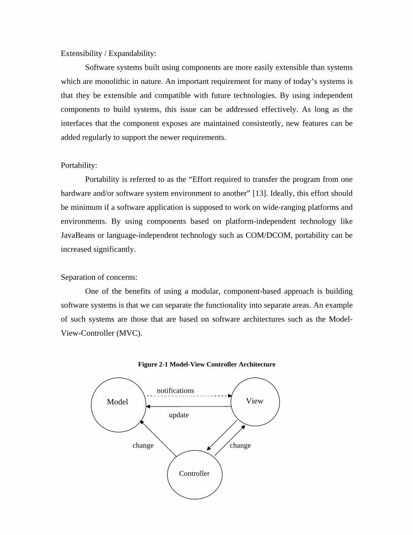
Separation of concerns:
One of the benefits of using a modular, component-based approach is building
software systems is that we can separate the functionality into separate areas. An example
of such systems are those that are based on software architectures such as the Model-
View-Controller (MVC).
Figure 2-1 Model-View Controller Architecture
change
update
change
Model
Controller
View
notifications

Error handling and security:
It is much more easier to handle errors related to specific components that make
up a modular system than in a single, large monolithic system. This also improves the
testability or the effort required to test if a program performs the intended function [13].
Security concerns can also be addressed for each specific component or for the system as
a whole.
Different standards for Component software:
CORBA: CORBA stands for Common Object Request Broker Architecture. The CORBA
specification was developed by the Object Management Group to be a vendor and
platform neutral means for developing component-based software. One of the goals of
CORBA is to have portability of the clients and object implementations. The object
request broker (ORB) is the central element in this architecture. It maintains a central
repository that contains a list of all services offered by the different components,
regardless of the location of the components in the system (local or distributed). Using a
client-server approach, objects within the client application request one or more services
from the ORB server. The figure below shows how a client makes a request for a service
from the ORB.
Client object
Object Request Broker (ORB)
Object implementation
Figure 2-2 CORBA Architecture - request scenario
The ORB implements the request to the remote object. Its function is to locate the remote
object, send the request, collect the results from the remote object and give it to the client
that placed that request. One of the main advantages of using CORBA is language
independency. The Client object can be programmed in any language (that CORBA has
language bindings for) and does not have to be in the same language as the CORBA
object. The ORB does the translation between the programming languages.
COM: The COM or Component Object Model specification was developed by Microsoft. It can
be defined as the following:
• An object-oriented, interface-based programming architecture
• A set of run-time services
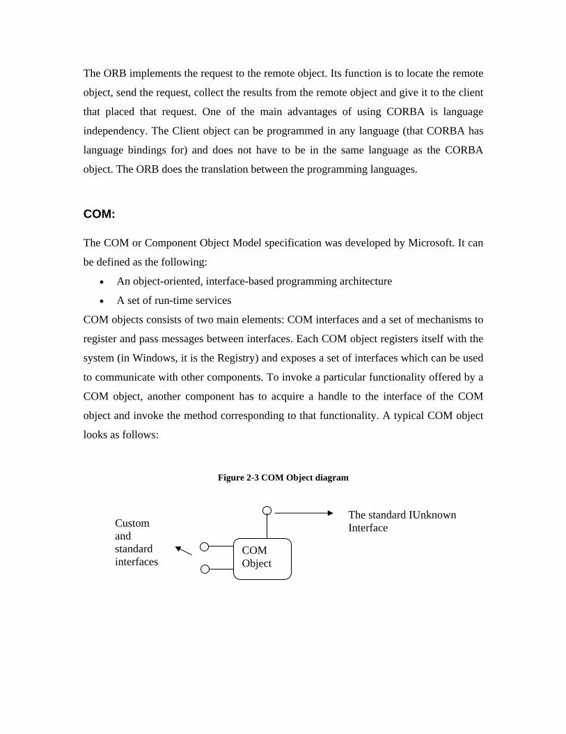
COM objects consists of two main elements: COM interfaces and a set of mechanisms to
register and pass messages between interfaces. Each COM object registers itself with the
system (in Windows, it is the Registry) and exposes a set of interfaces which can be used
to communicate with other components. To invoke a particular functionality offered by a
COM object, another component has to acquire a handle to the interface of the COM
object and invoke the method corresponding to that functionality. A typical COM object
looks as follows:
Figure 2-3 COM Object diagram
COM Object
The standard IUnknown Interface Custom
and standard interfaces
Benefits of COM:
COM is language independent:
COM is a programming architecture with a set of rules on how to create components. It is
not a programming language. In fact, the programmer has no restriction on the language
to be used to develop COM-based components. COM components can be created in
almost any language: C, C++, Visual Basic, Java, Delphi, COBOL etc. The only basic
requirement is that the language be able to generate the binary (vTable) layout of a COM
object.
COM provides location transparency:
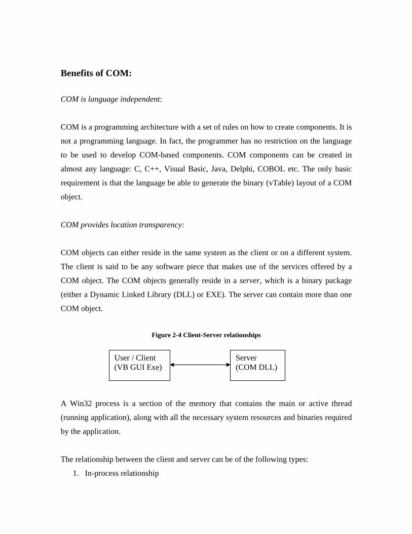
COM objects can either reside in the same system as the client or on a different system.
The client is said to be any software piece that makes use of the services offered by a
COM object. The COM objects generally reside in a server, which is a binary package
(either a Dynamic Linked Library (DLL) or EXE). The server can contain more than one
COM object.
Figure 2-4 Client-Server relationships
A Win32 process is a section of the memory that contains the main or active thread
(running application), along with all the necessary system resources and binaries required
by the application.
The relationship between the client and server can be of the following types:
1. In-process relationship
User / Client (VB GUI Exe)
Server (COM DLL)
2. Out-of-process relationship
3. Remote relationship
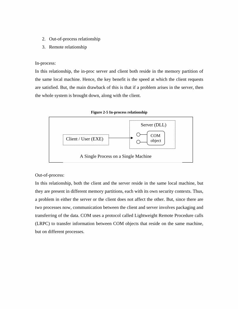
In-process:
In this relationship, the in-proc server and client both reside in the memory partition of
the same local machine. Hence, the key benefit is the speed at which the client requests
are satisfied. But, the main drawback of this is that if a problem arises in the server, then
the whole system is brought down, along with the client.
Figure 2-5 In-process relationship
Out-of-process:
In this relationship, both the client and the server reside in the same local machine, but
they are present in different memory partitions, each with its own security contexts. Thus,
a problem in either the server or the client does not affect the other. But, since there are
two processes now, communication between the client and server involves packaging and
transferring of the data. COM uses a protocol called Lightweight Remote Procedure calls
(LRPC) to transfer information between COM objects that reside on the same machine,
but on different processes.
Client / User (EXE)
Server (DLL)
COM object
A Single Process on a Single Machine

Figure 2-6 Out-of-Process local client/server relationship
Remote:
The remote relationship is very similar to the out-of-process relationship, except that the
client and the server reside on different machines. The communication between them is
done using the Distributed COM (DCOM) protocol which makes use of the Remote
Procedure Calls (RPC) to transfer information. Since, this involves sending data across
machines over a network, this is generally the slowest and most error-prone method of
COM object interaction.
COM is object-oriented:
The COM specification is completely object-oriented, meaning, it provides full support
for the main features of object-oriented technology – polymorphism, encapsulation and
inheritance. Every COM object encapsulates its information and provides access to it
only through properly defined interfaces. Other objects can inherit from a previously
defined COM object and provide newer and better features. The newly created COM
object will still provide the same interfaces as the older one. This makes sure that clients
using the older interfaces can still operate with the new COM object. This is one of the
major benefits of interface-based object-oriented programming. COM objects also
provide for ad-hoc polymorphism through their interfaces. Any COM object can re-
define the interfaces as they see fit.
LRPC
Client (Exe)
Proxy
Process A, Machine A Process B, Machine B Server (Exe) Stub
COM Object

In this thesis, we concentrate on the COM standard of component software. We illustrate
how the COM-based approach can be used to create components out of FORTRAN
subroutines and how the components can interact with each other. In Case Study 1, we
describe how a Ship Analysis component and an Optimizer component are created from
their corresponding FORTRAN code. We also illustrate how a visual interface developed
using Visual Basic can be used to orchestrate the communication between the two
components.
JavaBeans: The JavaBeans component specification is based on the Java programming language and
developed by Sun Microsystems. JavaBeans are portable, platform-independent
components written in Java. Essentially, beans are Java-classes that have the following
main ingredients:
• Events
• Properties
• Persistence
The beans are independent and reusable software modules, which can be either visual in
nature (AWT components such as Buttons) or invisible objects (data structure objects
such as queues, stacks or database-related objects).
All bean objects must have a set of properties which can be either read-only or read-
write. These properties essentially define the characteristics of the bean and can be read
or modified through a set of Getter-Setter methods. The beans interact with other bean
objects by sending and responding to events. Events are generated whenever something
happens in the bean (such as change in the value of a property). The JavaBeans Event
Model consists of three main components:
• Event Objects
• Event Listeners
• Event sources

The Event objects carry information about the events generated by the beans, which are
the event sources. Other bean objects which are interested in a particular event generated
by another bean (source), register themselves with the source. These objects are called
Event Listeners and a event notification is sent to all listeners whenever an event is
generated. Persistence is the ability of an object to store its state and retrieve it later.
Beans make use of the Java Object Serialization mechanism to accomplish persistence.
Visual “builder” programs are generally employed to assemble the beans and establish
links between them. In this aspect, they are similar to Visual Basic, where the VB IDE is
used to assemble ActiveX / OLE controls. The main advantage of JavaBeans compared to
its ActiveX counterpart is its ability to “run anywhere” and “reuse everywhere”. Also
JavaBeans have interoperability with other component architectures such as ActiveX
controls bridges (e.g., JavaBeans-ActiveX bridges).
Chapter 3
3. Mixed Language Programming (MLP):
Single language approach vs. MLP What is MLP? Rationale for MLP When to use MLP MLP approaches Key differences between languages (C, C++, FORTRAN, VB) Concept of DLLs Examples of MLP
Single-language approach vs. mixed-language programming approach: The use of a single programming language sometimes restricts the programmer from
expressing the functionality in the best possible way. No one language is suited for all
types of programming problems. Of the five main languages available (FORTRAN 77,
FORTRAN 90, C, C++ and Java), C++ and Java offer the most sophisticated object-
oriented approach, whereas FORTRAN offer simplicity and speed. It is necessary to
consider the choice of language before starting on a programming project, and sometimes
no one language is suitable for the whole project, and then a mixed language solution can
be best. [4].
What is Mixed Language Programming (MLP)?
Mixed-language programming refers to the use of multiple programming languages to
accomplish a programming task. A software application may make use of different
components and each of these components may have been developed in a different
programming language. MLP describes how these components based on differing
languages can be made to interact with each other.
Rationale for MLP:
The component-based development model described earlier works well for applications
built using the newer programming languages that support and recommend the object-
oriented approach, such as C++ and Java. But, for legacy applications built on
programming languages such as FORTRAN, it is not easy to build reusable components.
This is largely due to the fact that structured programming languages such as FORTRAN,
Pascal and C, do not support a component-based development methodology. Hence, to
create components out of structure code, we make use of the code wrapping component
adaptation technique described earlier.
In this thesis, we see how a console-based Multi-objective Genetic Algorithm
Optimization (MOGO) based ship design program developed in FORTRAN is
transformed into a Windows-based application with a visual interface. The MOGO
program consists of two main elements – the Ship Analysis part and the Genetic
Algorithm Optimizer. The original program consisted of a single main FORTRAN
program which invoked the functionality of both the elements, through sub-routine calls
to the different sub-routines and functions that made up the program. Our newly
developed program based on MLP techniques is similar to the Multi-disciplinary Design
Optimization (MDO) approach taken to build a MDO tool by Neu et al [19]. We have
built a visual interface for the MOGO program and developed two COM modules for the
Ship Analysis code and the Optimizer code. Each of the COM modules exposes a set of
interfaces that is used by the visual interface to invoke the corresponding functionality.
The COM modules in turn contain wrapper code in C++, which invokes the associated
subroutine in FORTRAN. The Visual front-end also has a Pareto-plot drawing capability
that displays the non-dominated frontier in a progressive manner.
When to use MLP:
Mixed-language Programming is a very good option when we have to develop
applications that make use of components developed in different programming

languages, or when we have to support or “upgrade” existing legacy software code. In
most of the cases, a MLP approach to development, invariably involves writing wrapper
code to eliminate conflicts between components. It also involves passing data between
the components and this can be problematic if the programming languages used to build
the components do not support inter-changeable data format. Even with languages such
as FORTRAN and C, which have equivalent data types, it is not an easy task to pass data
from a FORTRAN program to C program and vice versa. Considering, these “common”
problems that we encounter while using MLP, we also describe how a better tool-based
integration approach can be used to build/model applications using cross-language
components, in case study II.
Mixed Language Programming Approaches:
We seek to distinguish between two differing approaches in using Mixed Language
Programming for software development.
1. Traditional approach
2. Modern tool-based integration approach
Traditional approach:
The traditional approach is one of the most common and well-known methods of using
mixed language programming. FORTRAN77, FORTRAN90, C and C++ are by far the
most commonly used languages when it comes to scientific computing. In the past, most
of the computation intensive code was written mainly in FORTRAN77 which was well
suited for number crunching kind of applications. However, FORTRAN77 is a very old
language and has a lot of disadvantages when it comes to building large-scale
applications. As the popularity of C and C++ as scientific programming languages grew,
it became evident that in order to use and work with the vast amount of legacy code
written in FORTRAN, a cross-language programming approach would have to be used. C
and C++ have also been used to develop interfaces for FORTRAN programs, while the
computation code has been maintained in FORTRAN.
In this section, we briefly describe the following main languages and how they are used
in doing mixed language programming:
1. FORTRAN 77 and FORTRAN 90
2. C and C++
3. Visual Basic & Visual FORTRAN
FORTRAN 77 and FORTRAN 90:
FORTRAN is one of the oldest structured programming languages. It was developed at
IBM and a compiler for it was produced as early as 1957. However, a American National
Standard was not produced until 1966. The popularity of FORTRAN as a scientific
programming language is largely due to its unrivalled input/output facilities and support
libraries. It is also a very easy and straight-forward language to learn and program in,
especially for scientists and researchers. The compiled FORTRAN code is also highly
efficient. FORTRAN 77 is one of the most popular updates to the FORTRAN standard
and is also the most widely used among the FORTRAN versions. But, FORTRAN has
its own share of weaknesses and disadvantages: 6-character limit on symbolic names, the
fixed statement layout, and the need to use statement labels. There is no data type
checking facility and the language is quite liberal in allowing default values. Also control
and data structure facilities are absent, which prevents the programmer from developing
large-scale advanced applications.
In order to overcome these drawbacks and strengthen the language, a new standard called
FORTRAN 90 was introduced. F90 removes all the disadvantages in FORTRAN 77 and
provides a host of new features. It has almost all the features seen in the C and C++
programming languages, including dynamic memory allocation, pointer functionality,
column independent code, operator overloading, primitive data types, user-defined data
types, modules, recursive subroutines. Also F90 provides a variety of array handling
intrinsic functions, which are highly advanced and efficient.
C and C++:
C is one of the most popular systems-level programming languages. It is a structured
language developed by Dennis Ritchie and Brian Kernighan of AT&T Bell Labs. Unlike
FORTRAN, which is a High-level language (providing the features a programmer wants
in the language itself), C is a “middle-level language”. It only provides the basic building
blocks which can be used to develop different constructs and data structures. C was
mainly developed as a systems programming language, to develop programs that make
up the Operating systems, drivers, compilers, assemblers, interpreters, editors and other
utilities. The popularity of C has largely been its [10]:
• Compiler portability
• Elegant syntax with a variety of powerful operators
• Standard library concept
• Ability to access the hardware when needed through system-level routines
• Optimized and efficient code
The major drawback of C is that it is a structured programming language which is not
well-suited for building large-scale applications. During the 1980s, an explosive growth
in Object-Oriented technology was seen with the introduction of the Smalltalk
programming language. Object-oriented programming tries to address the drawbacks
seen in the structured programming approach. At this time, the popularity of C and the
growing acceptance of OOP, made Bjarne Stroustroup develop the C++ programming
language. C++ is largely seen as an extension of C with OOP capability. The two main
design goals of C++ were:
• Strong data type checking through the compiler
• User-extensible language through the concept of class
Some of the main advantages of C++ are as follows:

• Classes and objects
• Encapsulation
• Overloading
• Inheritance
• Polymorphism
• Templates
• Exceptions
Visual Basic and Visual FORTRAN:
Visual Basic:
Visual Basic is a High-level graphical programming language, developed by Microsoft. It
is derived from the older BASIC language. Visual Basic is a Windows programming
language, used to create Win32 applications. Unlike the other languages, visual basic
applications are entirely created using a Integrated Development Environment (IDE).
One of the major advantages of using Visual Basic is the ease with which Windows
applications can be created. The IDE greatly simplifies this, by allowing the programmer
to add Graphical User Interface (GUI) components such as Buttons, Text Boxes, Labels
etc., onto a form and adding the code corresponding to it. This process of building an
application is called Rapid Application Development or RAD, and Visual Basic is the
most popular RAD language.
Differences between Visual Basic and other languages:
Unlike C and FORTRAN, Visual Basic 4 and higher versions are object-oriented. They
allow a programmer to develop applications using classes and objects. VB also provides
object-oriented features such as encapsulation and polymorphism, but does not support
inheritance in the true object-oriented sense. But, the concept of interfaces and delegation
can be used in VB to achieve the same functionality of inheritance.

Visual Basic is an event-driven programming language. The programmer writes code in
functions or methods, for events such as clicking a button, clicking a menu item, typing
text in a text box, moving the mouse etc. Whenever a particular event occurs, the event
handler executes the code associated with that particular event.
Visual Basic also does not have inherent support for multi-threaded programming. This
can be accomplished by using the Win32 API (collection of C and C++ functions).
Visual Basic is an interpreted language. Unlike C, C++ and FORTRAN, VB code is not
compiled. The instructions in the executable are interpreted at run-time by dynamic-link
library.
Visual FORTRAN:
Compaq’s Visual FORTRAN is a complete development system that is comprised of
Compaq’s FORTRAN 95 compiler and Microsoft Visual Studio development
environment. This is one of the few languages that allows the programmer to directly use
Mixed language programming techniques in the Windows platform. The development
environment is the same as that for Microsoft Visual C++, with built-in support for visual
code editing and visual debugging. Visual FORTRAN can be used to build different
types of projects including, FORTRAN Console Application, FORTRAN Dynamic
Linked Library, FORTRAN QuickWin Application or FORTRAN Windows Application.
FORTRAN applications developed using Visual FORTRAN have full access to the
Win32 API. There is also support for the programmer to create FORTRAN clients that
access COM objects through the use of the Visual FORTRAN Module Wizard.
FORTRAN based COM servers can also be created. Numerous mathematical and
numerical libraries are available for doing scientific computing.

Key differences between the languages:
Each of the above mentioned languages have different data types, arrays, character
strings and user-defined data types. Here, we briefly describe the key differences between
them.
Data types: The data types in C and C++ are almost the same. C defines five main data types – int,
float, double, char and void. C++ provides two more: bool and wchar_t
bool stands for Boolean value (true of false), while wchar_t represents wide character.
FORTRAN supports the same data types as C and C++ and provides an additional
complex data type that can be used to represent complex numbers. This can be achieved
in C and C++ through the use of structure or class. Visual Basic provides support for
more advanced data types such as Currency, Date and Variant, in addition to the basic
data types.
Arrays:
Arrays are consecutive elements stored in consecutive memory locations in a computer.
Both C and C++ have a very good support for array manipulation. Array element access
is done through indices. In C, to copy array elements from one array to another, indices
are used to copy each element one by one, while in C++, a single assignment statement
can be used to copy entire array contents. FORTRAN has support for variable dimension
array segments in subroutines, which C and C++ do not provide. C and C++ array indices
start from 0 while FORTRAN’s default index range starts from 1. C and C++ use “row-
major ordering” of the array elements, while FORTRAN uses “column-major ordering”.
For example, the C array declaration: int A[3][2] is stored in memory as:
A[0][0] A[0][1] A[1][0] A[1][1] A[2][0] A[2][1]
A FORTRAN array declared as int A[3][2] would be stored in memory as:
A(1,1) A(2,1) A(3,1) A(1,2) A(2,2) A(3,2)
Hence, FORTRAN and C/C++ arrays appear as transposes of each other. Arrays in
Visual Basic by default have base 0 and also follow the row-major technique for ordering
the elements. VB also allows the programmer to define dynamic arrays at run time, using
the redim statement.
Characters and Strings:
Characters are one of the most fundamental data types found in most programming
languages and it usually occupies 1 byte data storage space. C and C++ treat strings as a
sequence of characters stored in consecutive memory locations. C++ also provides a
more convenient String class which can be used to instantiate a string and perform a
variety of string manipulation operations, without using any pointer arithmetic.
FORTRAN also allows the programmer to define both single character and multiple
character (strings) using the character data type. Visual Basic has fixed-length, variable-
length and Variant strings and also provides various high-level string manipulation
functions.
User-defined data types:
User defined data types (UDTs) are also called aggregate data types, since they are
formed by grouping one or more of the basic data types into larger data structures. C and
C++ support UDTs through struct and unions. C++, being object-oriented also provides
the concept of classes to create larger and better UDTs. FORTRAN77 does not have a
provision for UDTs, while FORTRAN90 and above do. Visual Basic also supports
creation of UDTs through classes and interfaces.
MLP issues:
As mentioned earlier, the major problem in using a Mixed language programming
approach lies in the fact that data has to be passed between programs written in different
languages. Clearly, some of the issues here are, the calling conventions to be used, data

transfer methods (parameter passing by call-by-value versus call-by-reference), naming
conventions to be followed, data types inter-operability and so on.
The following table lists the different data types that are available in FORTRAN, C/C++
and Visual Basic respectively:
Table 3-1 Datatypes in FORTRAN, C/C++ and Visual Basic
FORTRAN C & C++ Visual Basic INTEGER(1) char --- INTEGER(2) short Integer INTEGER(4) int, long Long REAL(4) float Single REAL(8) double Double CHARACTER(1) unsigned char String CHARACTER*(*) COMPLEX(4) struct complex4 {
float real, imag; };
COMPLEX(8) as above FORTRAN and Visual Basic, unlike C/C++ do not support the concept of unsigned
integer.
The equivalent data types in two different languages need not necessarily have the same
machine-level representation. For e.g., an Integer data type in FORTRAN may not have
the same number of bits as the Integer data type in C or Java. Since, there is no uniform
standard on how to use Mixed language programming, the programmer has to address all
these issues before a cross-language approach can be taken to develop software
applications.
In this section, we describe some of the MLP issues concerning C, C++ and FORTRAN
interoperability as they relate to programming on the Win32 platform.

Calling Conventions: The calling conventions refer to the protocol used by the language when it makes a call to
a function or a subroutine. A uniform calling convention is to be followed if the program
parameters are to be passed and used correctly. This is not a major issue when
programming with only one language, but when using multiple languages, it is very
important to ensure that the languages use the same convention. Otherwise, it might lead
to linking errors or more drastic run-time errors.
Table 3-2 C and FORTRAN Calling conventions [MS]
Language Parameter passing Stack cleared by
C/C++ Pushes parameters on the stack, in reverse order (right to left)
Caller
FORTRAN (__stdcall) Pushes parameters on the stack, in reverse order (right to left)
Called function
The __stdcall keyword can be specified in the C function prototype or declaration to call
a FORTRAN subroutine or function with the same calling convention. For e.g., the
following C function prototype can be used to call a FORTRAN subroutine:
extern void __stdcall FORTRAN_subroutine (int parameter_name)
When changes to the C code cannot be done, the calling convention can be specified in
the FORTRAN subroutine or function being called by using the C attribute as follows:
SUBROUTINE FORTRAN_subroutine [C] (parameter)
INTEGER*4 parameter
Naming conventions: The naming convention refers to how the language maintains the symbol name in the
object file (.obj). In order for a language to invoke the correct function or module present
externally, the correct name should be known. Case sensitivity and type decoration are
some of the reasons for this. The naming convention only affects the module name and
not the parameters that module accepts. If proper naming conventions are not followed, it
leads to linking problems (unresolved external error or unknown data symbols errors).
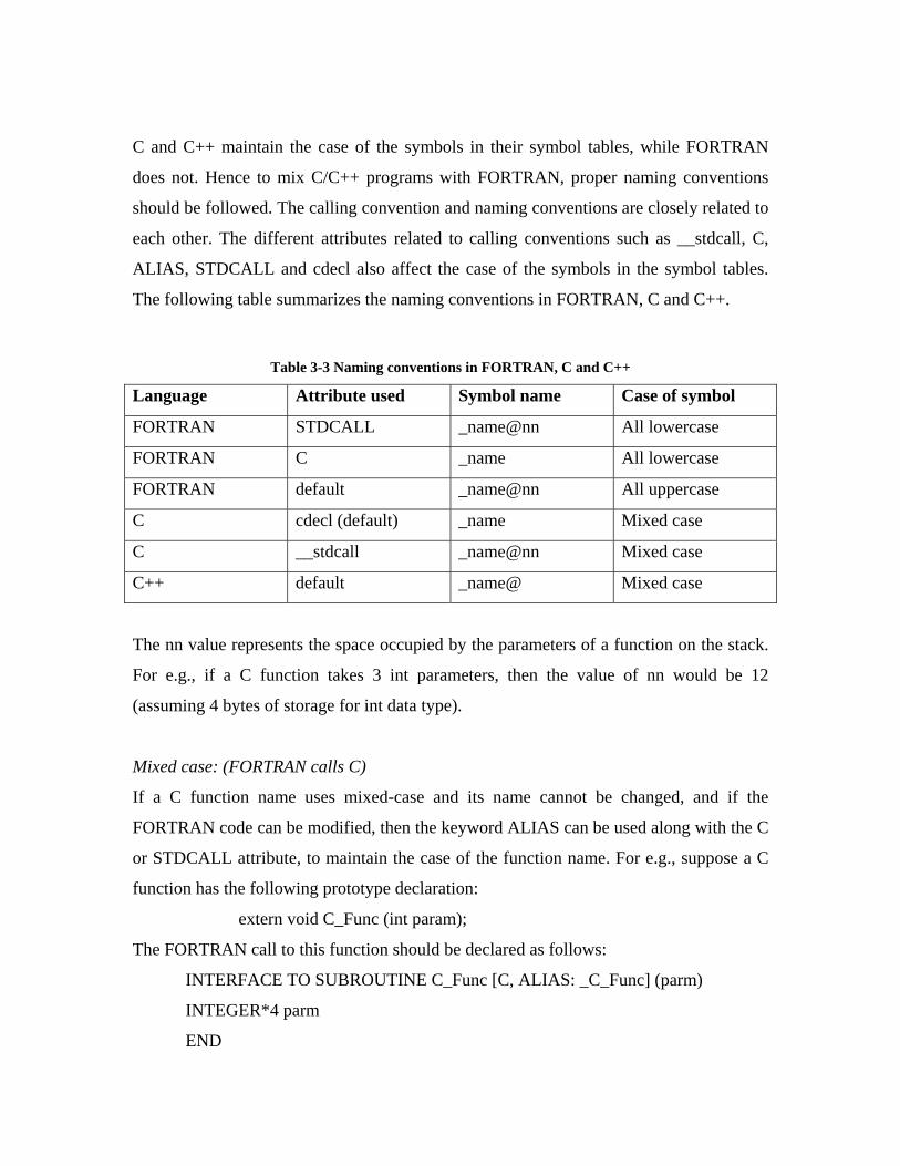
C and C++ maintain the case of the symbols in their symbol tables, while FORTRAN
does not. Hence to mix C/C++ programs with FORTRAN, proper naming conventions
should be followed. The calling convention and naming conventions are closely related to
each other. The different attributes related to calling conventions such as __stdcall, C,
ALIAS, STDCALL and cdecl also affect the case of the symbols in the symbol tables.
The following table summarizes the naming conventions in FORTRAN, C and C++.
Table 3-3 Naming conventions in FORTRAN, C and C++
Language Attribute used Symbol name Case of symbol
FORTRAN STDCALL _name@nn All lowercase
FORTRAN C _name All lowercase
FORTRAN default _name@nn All uppercase
C cdecl (default) _name Mixed case
C __stdcall _name@nn Mixed case
C++ default _name@ Mixed case
The nn value represents the space occupied by the parameters of a function on the stack.
For e.g., if a C function takes 3 int parameters, then the value of nn would be 12
(assuming 4 bytes of storage for int data type).
Mixed case: (FORTRAN calls C)
If a C function name uses mixed-case and its name cannot be changed, and if the
FORTRAN code can be modified, then the keyword ALIAS can be used along with the C
or STDCALL attribute, to maintain the case of the function name. For e.g., suppose a C
function has the following prototype declaration:
extern void C_Func (int param);
The FORTRAN call to this function should be declared as follows:
INTERFACE TO SUBROUTINE C_Func [C, ALIAS: _C_Func] (parm)
INTEGER*4 parm
END

Upper case: (C calls FORTRAN)
By default, FORTRAN generates all-uppercase symbol names. To call a FORTRAN
function from C, the use of the attribute __stdcall alone does not suffice. A proper C
declaration would be of the following form:
extern int SUM (int a, int b)
Lower case: (FORTRAN calls C)
If a function name appears as all-lowercase in the C declaration, then the attributes C or
STDCALL should be used in the FORTRAN declaration. The FORTRAN declaration
can however be used in any case, since the C or STDCALL attribute converts it to
lowercase.
Passing parameters:
When parameters are passed between C, C++, FORTRAN or other languages, the method
by which the parameter is passed is important. If a function expects a parameter’s value
and the calling function passes the parameter’s address (by reference), it will lead to
computational errors. Hence, it is important to specify explicitly if a call-by-value or call-
by-reference method is used when passing parameters.
C and C++ have the concept of address pointers which can be used, if parameters are to
be passed by reference. C and C++ pass parameters by value by default (except for arrays
which are passed by reference) and pointers should be used if call-by-reference is
required. In contrast, by default FORTRAN passes all parameters by reference. To pass
all data by value, the C or STDCALL attribute should be used.
If a call is made from C or C++ to a FORTRAN subroutine or function, the keywords
VALUE and REFERENCE can be specified in the parameter declaration of FORTRAN,
to distinguish between passing by value and reference. The following example illustrates
this:
C declaration:
extern void FORTPROC (int param1, float param2);
FORTRAN declaration:
SUBROUTINE FORTPROC (parm1, parm2)
INTEGER*4 parm1 [VALUE]
REAL*4 parm2 [REFERENCE]
END
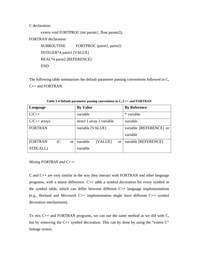
The following table summarizes the default parameter passing conventions followed in C,
C++ and FORTRAN:
Table 3-4 Default parameter passing conventions in C, C++ and FORTRAN
Language By Value By Reference
C/C++ variable * variable
C/C++ arrays struct { array } variable variable
FORTRAN variable [VALUE] variable [REFERENCE] or
variable
FORTRAN (C or
STDCALL)
variable [VALUE] or
variable
variable [REFERENCE]
Mixing FORTRAN and C++:
C and C++ are very similar in the way they interact with FORTRAN and other language
programs, with a minor difference. C++ adds a symbol decoration for every symbol in
the symbol table, which can differ between different C++ language implementations
(e.g., Borland and Microsoft C++ implementation might have different C++ symbol
decoration mechanisms).
To mix C++ and FORTRAN programs, we can use the same method as we did with C,
but by removing the C++ symbol decoration. This can by done by using the “extern C”
linkage syntax.
For e.g., to call a subroutine called CUBE in a FORTRAN program, we can use the
following statement:
extern “C” { int __stdcall CUBE (int number) }
If the C++ code cannot be modified, then the exact symbol decoration should be
obtained, using a tool like DUMPBIN (Visual Studio utility) and specified in the other
language.
One of the drawbacks of using the “extern C” linkage specification is that, this can be
used with only one declaration in a overloaded function. The other overloaded functions
will use the default C++ linkage mechanism.
Concept of Dynamic Linked Libraries (DLLs):
Dynamic Linked Library (DLL) files are a collection of modules that contain both data
and functions. Microsoft Windows applications use DLLs to perform functions such as
register or unregister, load or unload objects, processes and data in memory. DLLs
contain functions which can be used by any application, just by loading the library file in
memory at runtime. There are two types of functions that are present in DLLs:
• Exported functions
• Imported functions
Exported functions are used by other modules, while the imported functions are only
called from where the DLL is defined.
DLLs have the following advantages over static libraries:
• DLLs save memory and reduce swapping – applications that use static libraries
have their own copy of the library code assigned to their memory space. In
contrast, a single DLL present in memory can be shared by many applications at
the same time

• DLLs save disk space – different applications can share a single DLL present on
the disk. But, if a static library is used, then the library code is linked with each of
the applications increasing the disk space
• DLLs share functions – static libraries contain separate copies of data and
functions for each process, while DLLs share the functions, but keep separate
copies of data
• DLLs are convenient – when the functionality provided by the functions present
in a DLL change, we do not have to recompile or re-link the applications that use
the functions, as long as the function parameters and return types remain the
same. But, if changes are made in static libraries, then all the applications that use
them will have to be recompiled and/or re-linked.
DLLs act as the glue for tying together mixed-language programs. Functions and
modules written in different programming languages like FORTRAN, C, C++ or even
COBOL can be compiled into DLLs. The exported functions can then be used by other
programs by dynamically loading the library at runtime.
Examples of MLP:
In this section, we describe some of the specifics of MLP as it relates to programming in
the Win32 platform and give examples of how programs in different languages can
interact with one another. FORTRAN and C are two of the most commonly used
programming languages in scientific computing, and, there is invariably a need for
FORTRAN programs to interact with C programs and vice versa. A description of how
FORTRAN programs communicate with C routines and how C programs call FORTRAN
modules is given below.
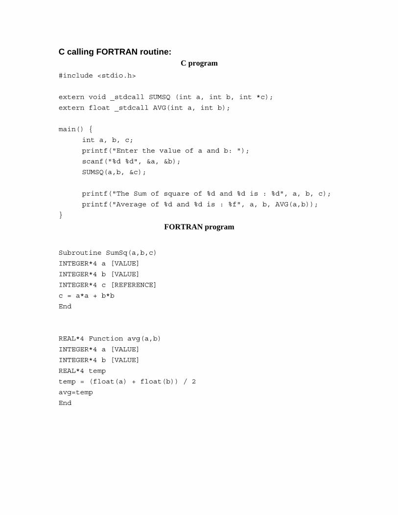
C calling FORTRAN routine: C program
#include <stdio.h>
extern void _stdcall SUMSQ (int a, int b, int *c);
extern float _stdcall AVG(int a, int b);
main() {
int a, b, c;
printf("Enter the value of a and b: ");
scanf("%d %d", &a, &b);
SUMSQ(a,b, &c);
printf("The Sum of square of %d and %d is : %d", a, b, c);
printf("Average of %d and %d is : %f", a, b, AVG(a,b));
}
FORTRAN program
Subroutine SumSq(a,b,c)
INTEGER*4 a [VALUE]
INTEGER*4 b [VALUE]
INTEGER*4 c [REFERENCE]
c = a*a + b*b
End
REAL*4 Function avg(a,b)
INTEGER*4 a [VALUE]
INTEGER*4 b [VALUE]
REAL*4 temp
temp = (float(a) + float(b)) / 2
avg=temp
End

Figure 3-1 Output of C calling Fortran
FORTRAN calling a C routine:
C Program #include <stdio.h>
float Avg (int a, int b) {
float avgval=0;
avgval = (float) (a + b) / 2;
return avgval;
}
void Sum2Nums (int a, int b, int* c) {
*c = a + b;
}
FORTRAN program program main
interface to real*4 Function Avg [C, ALIAS: '_Avg'] (a,b)
integer*4 a [VALUE]
integer*4 b [VALUE]
end
interface to subroutine Sum2Nums [C, ALIAS: '_Sum2Nums'] (a, b,
c)
integer*4 a [VALUE]
integer*4 b [VALUE]
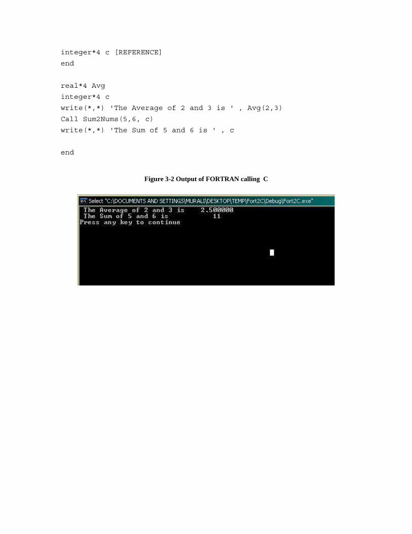
integer*4 c [REFERENCE]
end
real*4 Avg
integer*4 c
write(*,*) 'The Average of 2 and 3 is ' , Avg(2,3)
Call Sum2Nums(5,6, c)
write(*,*) 'The Sum of 5 and 6 is ' , c
end
Figure 3-2 Output of FORTRAN calling C
Chapter 4
4. Case Study I: MOGO
What is optimization? Difference between Single and Multi-objective optimization Multi-objective Genetic Algorithm based optimization MOGO for a ship design problem MOGO program – ship analysis and GA
o Function of the ship analysis part o Function of the GA
COM Architecture Drawbacks of this approach
Introduction to Multi-objective Genetic Optimization (MOGO):
What is Optimization:
Optimization is the process of either minimizing or maximizing a function or group of
functions of interest to us, such that it results in the best possible solution for a given
problem. The optimization process generally involves three main components:
1. Objective Function
2. Set of unknowns or variables
3. Set of constraints
The objective function is the system defined by the set of variables and constraints that
needs to be minimized or maximized. For a manufacturing process, this can be things
like, minimizing the cost of production or maximizing the efficiency of the
manufacturing process or maximizing the profit. The objective function generally
consists of a single objective, which needs to optimized (minimized or maximized).
However, there are problems that do not have any objectives and problems that have one
or more objectives.
The former category is generally called ‘feasibility’ problems, since they attempt to find
only a solution that satisfies the given constraints and do not try to optimize any
particular objective. The latter category of problems which have one or more objectives
are generally more common and the goal is to find a optimal solution that satisfies the
objective(s), under the given constraints.
The set of unknowns or variables affect the value of the objective function. For the
manufacturing process, this can be the amount of time spent on each activity or the
amount of resources used.
The set of constraints define what type of values the objective function variables can
take. It restricts some set of values, while allowing some others. In the manufacturing
process, the time variable cannot be negative. Hence one constraint that can be used, is
that all time variables should be positive.
Difference between Single and Multiple objective optimization:
When the optimization problem modeling a physical system involves only one objective
function, the task of finding the optimal solution is called single-objective optimization
When an optimization problem involves more than one objective function, the task of
finding one or more optimum solutions is known as multi-objective optimization [Deb].
The goal in a multi-objective optimization problem is to find that optimal solution or
group of solutions that satisfy the objectives and constraints in the best possible manner.
It is possible that the different objectives are not compatible with each other, hence
making it difficult, if not impossible to find an optimal solution. In that case, the multi-
objective problem is usually reformulated as a single objective problem by assigning
weights to the different objectives or reducing some of the objectives to constraints. (The
single objective optimization problem can hence be thought of as a degenerate case of
multi-objective problem).
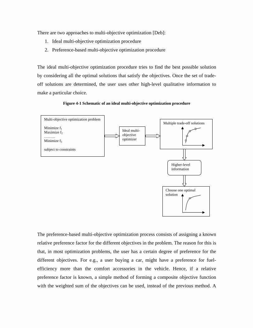
There are two approaches to multi-objective optimization [Deb]:
1. Ideal multi-objective optimization procedure
2. Preference-based multi-objective optimization procedure
The ideal multi-objective optimization procedure tries to find the best possible solution
by considering all the optimal solutions that satisfy the objectives. Once the set of trade-
off solutions are determined, the user uses other high-level qualitative information to
make a particular choice.
Figure 4-1 Schematic of an ideal multi-objective optimization procedure
The preference-based multi-objective optimization process consists of assigning a known
relative preference factor for the different objectives in the problem. The reason for this is
that, in most optimization problems, the user has a certain degree of preference for the
different objectives. For e.g., a user buying a car, might have a preference for fuel-
efficiency more than the comfort accessories in the vehicle. Hence, if a relative
preference factor is known, a simple method of forming a composite objective function
with the weighted sum of the objectives can be used, instead of the previous method. A
Choose one optimal solution
Multiple trade-off solutions Multi-objective optimization problem Minimize f1 Maximize f2 ……… Minimize f3 subject to constraints
Ideal multi-objective optimizer
Higher-level information

single objective function now summarizes the multi-objective problem and solving this
function gives a single optimal solution for most of the problems.
Figure 4-2 Schematic of the Preference-based multi-objective optimization procedure
Multi-objective Genetic Algorithm based optimization:
The classical way of solving multi-objective problems usually involves using the
preference-based method, where the multi-objective optimization problem is reduced to a
single objective problem by using a weight vector. In this process, the optimization
method works on a single candidate solution in each iteration and it is assumed that a
better and more optimal solution can be found in each successive iteration.
The Genetic algorithm or Evolutionary algorithm (EA) approach is the newer method of
search and optimization method, that mimics nature’s evolutionary principles to drive its
search towards an optimal solution [Deb]. The major difference between this approach
and the other classical optimization methods, is that the EAs use a generation of solutions
during each iteration, compared to a single solution in the classical method.
Multi-objective optimization problem Minimize f1 Maximize f2
…………… Minimize fn subject to constraints
Higher-level information
Estimate a relative importance vector (w1w2…wn)
Single objective optimization problem F = w1f1+w2f2+ … + wnfn Or a composite function
Single-objective optimizer
One optimal solution

A new population of solutions (generation) is generated during each run, from the
previous set. A ‘fitness’ function is then used to determine if the generated solution(s) is
optimal. To form a new population, the individuals are selected according to their fitness,
based on a selection procedure. Since, selection alone cannot introduce any new
individuals to the population, two operations called crossover and mutation are also
employed. More information about these techniques can be found in [Back96, Mic96,
Mit96]
The main advantage of using this approach is that, if the optimization problem has one
optimal solution, the EAs can be expected to converge to that single solution. And, if the
problem has more than one solution, then the EAs can be used to generate multiple
optimal solutions for the different objectives. Hence, the genetic algorithm based
approach is a very good solution for multi-objective optimization problems.
Since, the EAs always work with solutions generated from previously known solutions,
the drawback of any EA is that the solution generated is only better compared to the
previously generated solution. Hence, there is no way to actually test if the solution is
optimal or not. For this reason, the EAs are generally best used for problems where the
search space is very large and there is no easy way to test for optimality. Another
drawback is that the EAs do not have any way of converging, if there is no single optimal
solution. The only way of allowing an EA to stop is to specify the number of generations
or iterations it should explore or set a specific length of time for it to search.
MOGO for ship design problem
The multi-objective genetic optimization technique can be used for a variety of problems
that require finding an optimal solution based on multiple objectives. Here, we consider a
ship design problem which consists of two main objectives: Cost and Effectiveness.
The goal is to find the optimal design of a ship that has the highest effectiveness for a
given cost, given an initial set of constraints. A Multi-Objective Genetic Optimization

program has been written in FORTRAN, that finds a group of optimal solutions for the
above problem.
The MOGO program is made of two main parts:
1. Ship Analysis code
2. Genetic Algorithm (GA)
The program in the current form consists of multiple subroutines that are invoked by the
main program during the course of the optimization process. Our goal is to separate the
different FORTRAN subroutines into separate components based on their functionality
(Ship analysis code versus Genetic algorithm optimization code). This can be achieved
by following any of the previously discussed component-based development strategies.
We have achieved this goal, by creating two COM-based components, one for the ship
design function and the other for the optimization function. A simple visual user interface
is also provided to the program, to allow the user to set the optimizer’s parameters, such
as population size and number of generations. This interface has been developed using
Visual Basic. The interface also provides the functionality of viewing the Pareto-plot as
the program is running. This graph shows the formation of the non-dominated frontier
composed of the optimal solutions.
By delegating all ship analysis functionality to the ship analysis component and the
optimization functionality to the GA component, the program has been made more
modular and flexible. The advantage of separating the main program parts into individual
components is that, the optimizer component can potentially be replaced with a different
GA component and any changes made to the ship analysis code or the GA code will be
independent of each other.
MOGO program – ship analysis part and GA
Function of the Ship Analysis Component:
The ship analysis component is responsible for producing the ship design for each ship of
the population during every generation. Some of the main functions of this component
involves, calculating the electrical load and auxiliary machinery rooms, creating the
initial population for the search, calculating the sustained and maximum speed of the
ship, as well as the endurance, the initial stability parameters, the fuel weight and volume
of all tanks, the weight (full load and light weight), the required power balance for
sustained speed condition etc.
Function of the GA:
The Genetic Algorithm used is called a Niched Pareto Genetic Algorithm [Horn94]. The
goal of the GA is find a set of non-dominated solutions. The non-dominated solutions
constitute the best solutions for the problem with respect to the multiple objectives. The
set of all possible tradeoffs among the multiple objectives constitutes the non-dominated
solutions. In the objective space, these non-dominated solutions lie on a surface known as
the Pareto optimal frontier or Pareto front. The GA used in this application tries to find a
representative sampling of solutions along the Pareto front.
Using the given input design parameters, the optimizer randomly creates a set of balanced
ships. Since the objectives of interest in this problem, are the Total Ownership Cost
(TOC) and Overall Measure of Effectiveness (OMOE), the optimizer compares the ships
based on these two attributes. From the initial generation, a second generation of ships is
created and a ship design is selected based on its cost versus effectiveness. In each new
generation, a small fraction of the design variables are replaced with new randomly
generated design variables. The ship designs at the end of each new generation re spread
across the cost-effectiveness frontier. The optimizer runs for about 100 generations after
which a non-dominated frontier or Pareto front can be established after which the user
can select a particular ship design. The non-dominated frontier consists of all those ships
designs have highest measure of effectiveness a given cost.
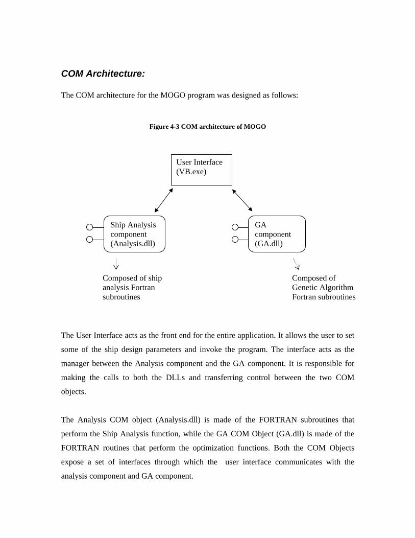
COM Architecture: The COM architecture for the MOGO program was designed as follows:
Figure 4-3 COM architecture of MOGO
The User Interface acts as the front end for the entire application. It allows the user to set
some of the ship design parameters and invoke the program. The interface acts as the
manager between the Analysis component and the GA component. It is responsible for
making the calls to both the DLLs and transferring control between the two COM
objects.
The Analysis COM object (Analysis.dll) is made of the FORTRAN subroutines that
perform the Ship Analysis function, while the GA COM Object (GA.dll) is made of the
FORTRAN routines that perform the optimization functions. Both the COM Objects
expose a set of interfaces through which the user interface communicates with the
analysis component and GA component.
User Interface (VB.exe)
Ship Analysis component (Analysis.dll)
GA component (GA.dll)
Composed of ship analysis Fortran subroutines
Composed of Genetic Algorithm Fortran subroutines

The original MOGO program was a console-based application that had a FORTRAN
main program in which the values for the number of generations and population size were
fixed. The VB-based user interface is a windows executable application that has
provision for accepting the number of generations, population method, population size
and the penal factor. It also provides an option to select the file containing the design
parameters if the population method is either forced or single.
Figure 4-4 MOGO User Interface
The “View Plot” function allows the user to view the Pareto-plot of the current
generation of ship designs. The Pareto-plot shows a graph of the Overall measure of
Effectiveness and Total Ownership Cost, as a Scatter-Plot diagram. Each successive
generation is plotted and the formation of the non-dominated frontier can be seen as the
program runs. Since, the number of generations is usually quite large (e.g., 100), the
results are plotted once for every 10 generations.
The figure below shows the plot of OMOE vs. TOC. As the generations progress, the
designs with highest measure of effectiveness for a given ownership cost are produced
and are plotted. These designs constitute the non-dominated frontier.
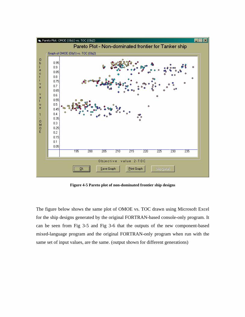
Figure 4-5 Pareto plot of non-dominated frontier ship designs
The figure below shows the same plot of OMOE vs. TOC drawn using Microsoft Excel
for the ship designs generated by the original FORTRAN-based console-only program. It
can be seen from Fig 3-5 and Fig 3-6 that the outputs of the new component-based
mixed-language program and the original FORTRAN-only program when run with the
same set of input values, are the same. (output shown for different generations)

Figure 4-6 Shuttle Tanker non-dominated frontier ship designs
Drawbacks of the above MLP approach:
Even though the above MLP-based approach of building component-based software
works well, it is not without any drawbacks. Converting a program written entirely in one
language such as FORTRAN into a multi-language component-based application
involves a considerable amount of work. Almost all the MLP issues identified in chapter
3 such as naming conventions, parameter passing methods, calling conventions, data
transfer issues between programming languages come into play. Also, the number of calls
between the different routines in different languages involves a considerable amount of
overhead which can be an issue when programs involve a large number of iterations
(such as the above ship design program where the number of generations and population
size are very high)
In the next section, we discuss a newer and better way of building component-based
software applications using a tool-based modeling and integration approach. We consider
the use of a software tool called ModelCenter developed by Phoenix Integration and
describe how it can be used to solve the same Multi-objective Genetic Optimization

based ship design problem. We will illustrate how ModelCenter can be used to interface
with a ship design program called ASSET, which performs functions similar to the
Analysis component in the previous approach. The genetic algorithm function can be
performed by a ModelCenter plug-in called Darwin, developed by Adoptech Inc,.
Currently this functionality has not been included in the ModelCenter application yet and
is part of the future work.
Chapter 5
5. Case Study II: ModelCenter-ASSET
What is ModelCenter? ASSET-Ship design & Analysis program Basic System Architecture Wrapping ASSET modules as Script Components
o Steps to create a Script Component Assembly components Driver component
o Testing for convergence Optimizer component – Darwin Advantages of using a tool-based integration approach Disadvantages
In this chapter, we describe an alternate and more convenient way of building
component-based systems. Even though the approach is not entirely applicable to
constructing all types of component software systems, it provides an simple, easy and
effective way to model component systems. We specifically describe how a systems
design and integration tool such as ModelCenter can be used to create models, which are
made of the components. The main objective of this chapter is to describe in detail an
alternate way of solving the same problem of multi-objective genetic optimization for
ship design and evaluate the tradeoffs of using this approach compared to the previous
MLP approach.
What is ModelCenter?
ModelCenter is a Windows application that enables the users to create Models by
integrating individual analysis programs, which can be either commercial analysis
programs, in-house codes (FORTRAN programs), Microsoft Excel workbooks or
applications written in the ModelCenter environment. It is a tool that allows engineers to
design and analyze systems.

Figure 5-1 ModelCenter User Interface
ModelCenter is a client for the Analysis Server program, which is a separate program that
can reside on the same system that ModelCenter runs or on a different system on the
network. The analysis programs reside on the Analysis server and the Analysis Server
itself can run on both the Windows NT platform and Unix platform. The Analysis Server
is a Java-based program that accepts client connections on a specific port. Using
ModelCenter, a connection can be established to the Analysis Server and the analysis
programs available on the server can be browsed using a server browser.

Figure 5-2 ModelCenter-Analysis Server
Once the programs to be used in ModelCenter have been identified, they can be added to
the ModelCenter environment by double clicking on the program name in the server
browser.
Figure 5-3 Server browser in ModelCenter
The Analysis server provides different ways to wrap the analyses programs in the server
for use in ModelCenter:
• FileWrapper: This utility allows the user to provide a input file containing a set of
inputs for the program, run the program and parse the resulting output file
• ExcelWrapper: This can be used to wrap Excel spreadsheet programs by making
use of Excel’s COM features. The inputs and outputs can be specified in the cells
of the spreadsheet.
• ScriptWrapper: A general purpose wrapping tool using any Active Scripting
language (such as VBScript or JScript) or the Java language itself
Analysis server
Analysis Program
Analysis Program
• JavaBeans: Since the Analysis server program is based on Java, it supports other
analysis programs written in Java.
The analysis programs wrapped in such a manner in ModelCenter are called components.
The components generally have a set of inputs and outputs. The Analysis server is not the
only way to create components in ModelCenter. There are other ways such as using:
• Script Components
• Common components
Script components provide a easy and convenient way to create custom components.
Each script component has an associated script with it that contains the main logic for the
program. The script component can also be used to wrap other programs. This is the
approach that is used in solving the ship design problem.
ModelCenter has the capability to link together different analysis programs (components)
through the use of input and output variables. Links are established between the output of
one component and the input of another component using the Link Editor. The Link
editor also allows the user to edit, view or delete the links.
ASSET – Ship Design and Analysis program:
ASSET stands for Advanced Surface Ship Evaluation Tool. It is a family of integrated
and interactive ship design synthesis computer programs. It is very similar to the ship
analysis component used in the previous MLP based approach. The ASSET program
consists of multiple design synthesis modules corresponding to different aspects of the
ship design, such as Hull, Machinery, Deckhouse, Propeller, Resistance etc. Each of these
modules has to be run consecutively in a pre-set order to produce a complete ship design.
ASSET does not provide an optimizer and is capable of producing only one balanced ship
design for a given set of input ship design parameters. This drawback can be addressed
through the use of the Optimizer component (Single objective) available in ModelCenter
or through the use of the Darwin plug-in (Multi-objective) for ModelCenter.
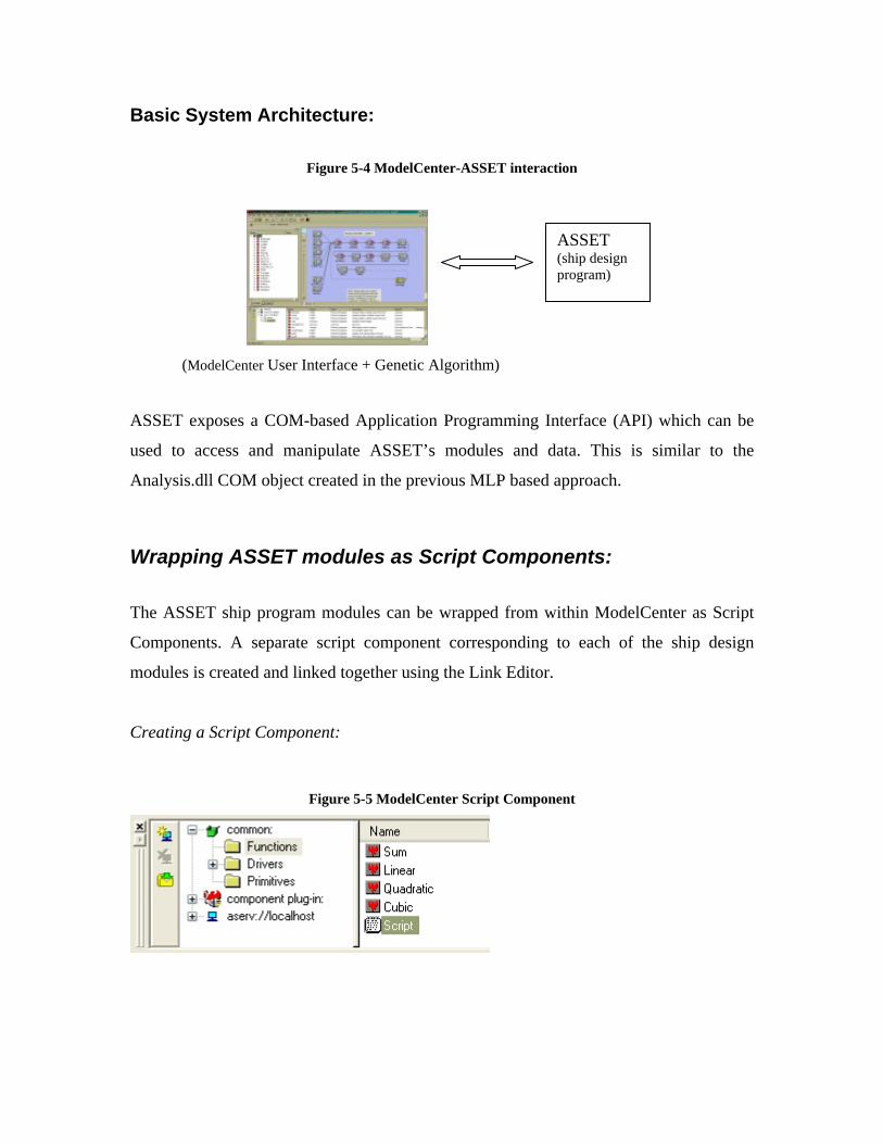
Basic System Architecture:
Figure 5-4 ModelCenter-ASSET interaction
(ModelCenter User Interface + Genetic Algorithm)
ASSET exposes a COM-based Application Programming Interface (API) which can be
used to access and manipulate ASSET’s modules and data. This is similar to the
Analysis.dll COM object created in the previous MLP based approach.
Wrapping ASSET modules as Script Components:
The ASSET ship program modules can be wrapped from within ModelCenter as Script
Components. A separate script component corresponding to each of the ship design
modules is created and linked together using the Link Editor.
Creating a Script Component:
Figure 5-5 ModelCenter Script Component
ASSET (ship design program)
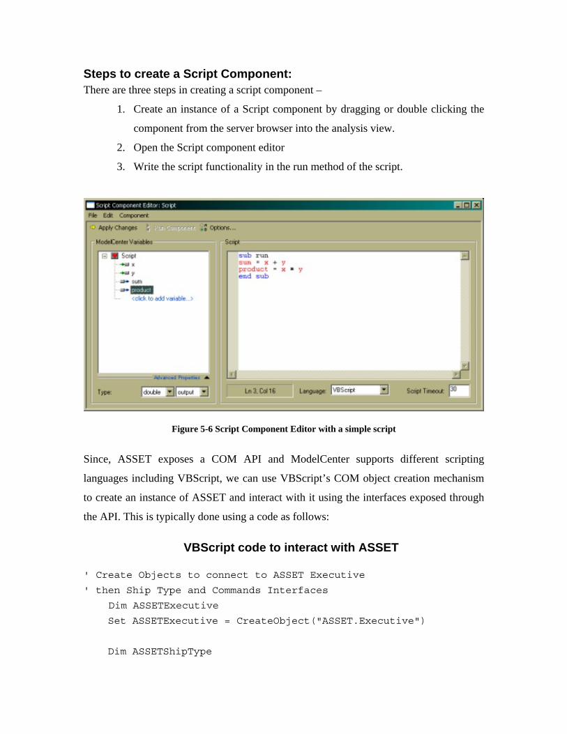
Steps to create a Script Component: There are three steps in creating a script component –
1. Create an instance of a Script component by dragging or double clicking the
component from the server browser into the analysis view.
2. Open the Script component editor
3. Write the script functionality in the run method of the script.
Figure 5-6 Script Component Editor with a simple script
Since, ASSET exposes a COM API and ModelCenter supports different scripting
languages including VBScript, we can use VBScript’s COM object creation mechanism
to create an instance of ASSET and interact with it using the interfaces exposed through
the API. This is typically done using a code as follows:
VBScript code to interact with ASSET ' Create Objects to connect to ASSET Executive
' then Ship Type and Commands Interfaces
Dim ASSETExecutive Set ASSETExecutive = CreateObject("ASSET.Executive")
Dim ASSETShipType
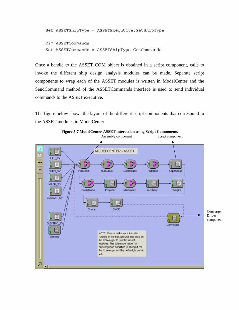
Set ASSETShipType = ASSETExecutive.GetShipType
Dim ASSETCommands
Set ASSETCommands = ASSETShipType.GetCommands
Once a handle to the ASSET COM object is obtained in a script component, calls to
invoke the different ship design analysis modules can be made. Separate script
components to wrap each of the ASSET modules is written in ModelCenter and the
SendCommand method of the ASSETCommands interface is used to send individual
commands to the ASSET executive.
The figure below shows the layout of the different script components that correspond to
the ASSET modules in ModelCenter.
Figure 5-7 ModelCenter-ASSET interaction using Script Components
Assembly component Script component
Converger – Driver component

The ModelCenter model contains all the script components linked together in a linear
manner, since, ASSET requires that the ship design modules be run in a certain order.
The components HULL_SV, DKHS_SV, MACH_SV, COMBAT_SV, ELECTRIC_SV,
MANNING are used to set a group of ASSET design parameters before running the ship
design modules. These parameters are set after a baseline ship design is loaded from a
databank in ASSET.
Assembly components: Groups of similar components can be grouped together to form an Assembly component.
Assembly components can be used to hierarchically manage different components in the
model. The entire ModelCenter model is by itself an Assembly component.
Figure 5-8 Assembly components
Assembly component Assembly component contents
The components HullGeom, HullSubDiv, Deckhouse, HullStruc, Resistance and
Machinery are made into Assembly components, while the other components are just
individual script components. The reason for this is that HullGeom, HullSubDiv,
Deckhouse etc., have a set of design variables that correspond to each of the associated
ASSET ship design modules. The values for the design variables need to be set only once
during the first run of the module in ASSET and hence they are separated from the actual
script component that invokes the call to the ASSET module.
Fig. 4.8 shows the HullGeom Assembly component and the contents of it. The
HullGeom_DV component contains the script for setting the values of the design
variables (Fig 4.9 ) in ASSET during the first run.
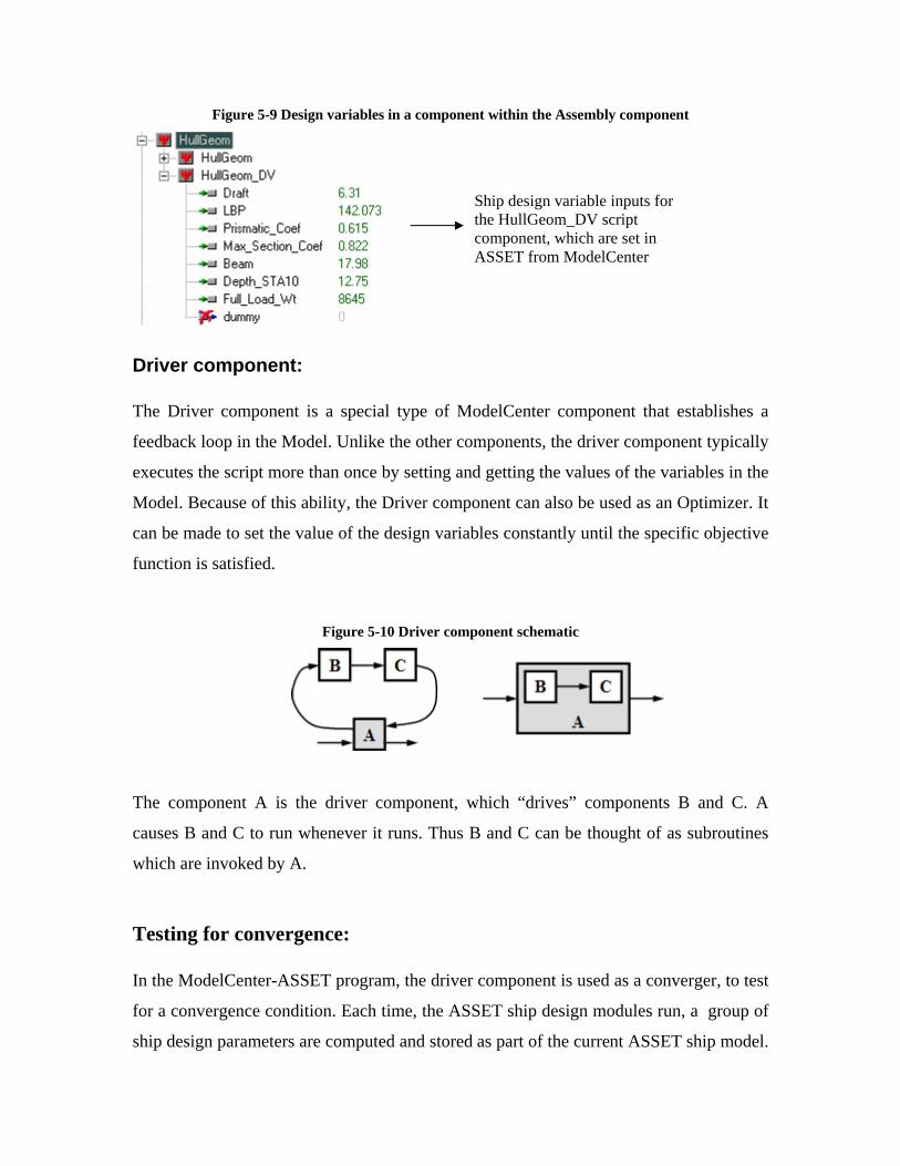
Figure 5-9 Design variables in a component within the Assembly component
Driver component: The Driver component is a special type of ModelCenter component that establishes a
feedback loop in the Model. Unlike the other components, the driver component typically
executes the script more than once by setting and getting the values of the variables in the
Model. Because of this ability, the Driver component can also be used as an Optimizer. It
can be made to set the value of the design variables constantly until the specific objective
function is satisfied.
Figure 5-10 Driver component schematic
The component A is the driver component, which “drives” components B and C. A
causes B and C to run whenever it runs. Thus B and C can be thought of as subroutines
which are invoked by A.
Testing for convergence: In the ModelCenter-ASSET program, the driver component is used as a converger, to test
for a convergence condition. Each time, the ASSET ship design modules run, a group of
ship design parameters are computed and stored as part of the current ASSET ship model.
Ship design variable inputs for the HullGeom_DV script component, which are set in ASSET from ModelCenter

Sustained speed is one of the parameters computed by ASSET during every run. In its
current form, the program tests this parameter for convergence. The tolerance value can
be set by the user and the default value is set 0.1.
Figure 5-11 Driver component to check for convergence
This means that the converger will fetch the computed value of sustained speed from
ASSET during every run, and compare it with the previously obtained value for
convergence. Once the tolerance condition is met (i.e., the difference between the two
values is less than the tolerance value), the converger stops re-running the model.
Optimizer component ModelCenter provides an optimization tool which can be used to set up simple
optimization problems by specifying the objective function, design variables and
constraints. The optimizer is based on the Gradient optimization technique and is capable
of solving optimization problems involving a single objective.
ModelCenter also has the capability of using external software components, as plug-ins.
Adoptech’s Darwin Optimizer plug-in is one such component, which can be used with
ModelCenter. Darwin is a Genetic Algorithm based optimizer component and is capable
of supporting both single and multi-objective optimization problems. Darwin provides
support for viewing the optimization progress and the final results of the optimization in a
visual manner. The user interface for the Darwin plug-in is also very similar to the
ModelCenter built-in optimization tool, making it easy for the user to set up an
optimization problem.

Advantages of the tool-based integration approach:
Tools such as ModelCenter-Analysis Server provide the user with a lot of flexibility and
options in designing or modeling systems. Though ModelCenter does not allow the user
to build component-based systems in the traditional way emphasized by Component-
based Software Engineering, it is still a very useful way to build and model component
systems. ModelCenter greatly simplifies automating and integrating design codes.
ModelCenter supports different types of components – Analysis components, Geometry
components, Driver components and Assembly components. There are also different
methods of creating components such as using Analysis server, Script components,
Common components.
The major advantage that ModelCenter holds over the traditional Mixed-language
programming technique is its ability to interact with any program residing on the
network. The Analysis Server plays a major role in this, by providing a simple but
effective way of wrapping the program and converting it into a reusable component. The
Analysis Server acts as the server hosting the components, while ModelCenter is a
lightweight client that interacts with these components. Using the traditional MLP
technique, we would have to manually program the “client” to transfer and fetch data
from a program residing elsewhere. This would involve using other techniques such as
Remote Procedure Calls (RPCs), which are actually hidden from the user in the case of
ModelCenter-Analysis Server. This is a great advantage since the users need not be
concerned about how to interact with components which are distributed over a network.
The Analysis Server provides a great amount of flexibility in creating components of
various types of programs. Using the FileWrapper utility provided with Analysis Server,
the user has to only invest the time to create a wrapper for a particular program to make it
into a component. The wrapper allows the user to provide the input for the program,
using the “set” operation and retrieve the output of the computation using the “get”
operation. The program itself can be run using the “execute” command. Other ways of
creating wrappers include using the PerlWrapper, ScriptWrapper, ExcelWrapper and

JavaBeans authoring mechanism. The following table briefly summarizes the
functionality of the various wrapping schemes available in Analysis Server [PhxAS]:
Table 5-1 Functionality of wrapping tools in ModelCenter
Authoring Tool Purpose Authoring Complexity
FileWrapper Wrapping file-based legacy software and commercial programs
Easy to moderate
ExcelWrapper A utility for publishing Excel spreadsheets as components
Easy
ScriptWrapper
A general purpose wrapping tool using any Active Scripting language (such as VBScript or JScript) or the Java language itself
Easy to moderate
PerlWrapper Authoring simple components, based on the PERL programming language
Easy
Java Extremely flexible, general purpose wrapping and authoring
Moderate to difficult
Hence, the Analysis Server plays a key role in how the programs are treated as
components.
Some of the disadvantages found in ASSET, such as lack of optimization support, ability
to run the ship design modules once (user has to run synthesis procedure every time), can
also be overcome using ModelCenter. ModelCenter allows the user to incorporate a
convergence loop (using the Driver component), which can run the ASSET modules a
pre-defined number of times, or until a particular parameter converges. Also, the Darwin
optimizer component of ModelCenter can be used to extend ASSET’s basic ship design
functionality, to include multi-objective optimization.
Another major advantage of using ModelCenter is its support for plug-ins. Plug-ins such
as the MathCAD, Darwin, Excel and Matlab plug-in, allow the user to interact with
programs written in other languages such as MathCAD, Matlab or Excel spreadsheets.
The plug-ins play a major role in extending the functionality of ModelCenter.
Disadvantages of using a tool-based integration approach:
Though the tool-based integration approach provides a lot of advantages in building
component-based systems, there are some visible drawbacks in it. As with any new tool,
development using tools such as ModelCenter and Analysis Server involves a learning
curve for the programmer, though this is much smaller than that of learning mixed
language programming. This approach is not an easy or viable option, when creating and
modeling component systems on a small scale. If the programmer has to just create a
DLL or EXE from a FORTRAN, C or C++ program, so that it can be used with other
smaller programs, it is much easier to use the traditional MLP technique, than use the
ModelCenter environment. However, the larger the component-based system, the more
tedious it becomes using the MLP method. In that case, the tool-based method is better
suited.
Another main drawback of this approach is the dependency on other ‘external’ programs
such as ModelCenter and Analysis server, which are essential to creating and maintaining
the component-based systems. It is not possible to just create and model the component
system using the tools, and use them separately without the tools. For e.g., models
created in ModelCenter and programs wrapped using the FileWrapper program of
Analysis server cannot be used separately without ModelCenter or Analysis server. The
tools are the key part of this type of development methodology. Hence, unlike the DLL
components created using the MLP techniques, Script components, Analysis components,
Driver components and Assembly components created using ModelCenter cannot be used
outside of the ModelCenter environment.
The ModelCenter environment is well suited for building and modeling systems made of
disparate components. However, it does not allow the programmer to build a custom user
interface (UI), such as the one we developed in Visual Basic in Case Study I. The
drawback is that the user is compelled to input the values for the system input parameters
using ModelCenter’s Component Tree or Script Editor. It is not possible to create a
different UI other than the default way of creating and connecting components in
ModelCenter. Even though ModelCenter offers three different views of the model –
Analysis view, Geometry view and Report view, the view that is most often used to view
the model is the Analysis view. If the system being modeled has a lot of components
interacting with each other through the links (created using the Link Editor), the Analysis
view can quickly get very crowded with all the links crisscrossing between the
components. The Zoom tool in the Analysis view however mitigates this a little bit.

Conclusion Mixed language programming technique is one of the oldest and best known approaches
towards developing component-based software applications. It is mostly used in the
scientific community because of the large availability of scientific libraries developed in
different programming languages. It is a very effective and useful way of building
component-software if the components have been developed in multiple languages. It
allows the programmer to use existing components without re-writing or developing them
in another language. However, this approach is only effective if there is a complete
understanding of all issues involved in using multiple languages to build a software
system. This is usually not easy, since each language has its own set of unique features
and limitations. There are a lot of issues in using a mixed language approach and naming
conventions, data integration are just a few of them.
One of the goals of this thesis work was to use this approach to convert a pure
FORTRAN-only ship design software into a component-based cross-language software
system. This work involved creating two modules based on the COM programming
model and a visual user interface that also acts as a coordinating manager between the
two modules. This was successfully accomplished and the console-based application was
converted into a graphical windows-based application.
A newer tool-based approach for modeling and building component-software systems is
also discussed as part of the thesis work. This approach is used to construct a similar
solution to the ship design problem and it involves using Phoenix Integration’s
ModelCenter and Analysis Server software, along with a separate ship design software
ASSET. This approach uses code-wrapping techniques to assemble disparate components
into a heterogeneous system. The advantages and disadvantages of using this approach
are also discussed.

Future work:
There is a lot of scope for improvement in the current study of component-based software
development using a mixed-language approach and a tool-based approach. The
ModelCenter-based solution is not fully comparable to the mixed language based
solution, since the former lacks an optimizer as part of the solution. The current
implementation of the program does not include the Darwin optimizer that can be used in
the ModelCenter environment. Inclusion of the Darwin optimizer would allow the
programmer to develop a solution where multiple optimal solutions can be generated by
running the program through multiple iterations. Also, for the comparison to be more
accurate and equivalent, the same FORTRAN ship code should be used to develop the
solution using ModelCenter. At present, the ModelCenter solution uses different ship
design analysis software called ASSET, which performs a similar function as that of the
FORTRAN code.
Another area of work that is worthy of study is development of the same solution using a
different component integration tool such as BABEL and comparing this solution with
that developed using the ModelCenter tool. This would enable us to develop a better and
fair comparison of developing component-based software using components written in
multiple languages. The current thesis work can be extended in this direction, as this will
also give a better understanding of the advantages and disadvantages of using a tool-
based approach for building large-scale software systems. This will also help future
developers and programmers decide the best possible approach for a given problem,
among the various tool-based development methodologies.

References:
[1] Benjamin A. Allan, Robert C. Armstrong, Alicia P. Wolfe, Jaideep Ray, David E. Bernholdt, and James A. Kohl. The CCA core specification in a distributed memory SPMD framework. Concurrency and Computation:Practice and Experience
[2] J.A. Bergstra and P. Klint. The ToolBus -- a Component Interconnection
Architecture--. P9408, Programming Research Group, University of Amsterdam, Amsterdam, 1994. http://citeseer.nj.nec.com/bergstra94toolbus.html
[3] Hayco de Jong and Paul Klint. ToolBus: The Next Generation,
http://citeseer.nj.nec.com/561377.html
[4] P.Klint and P.Olivier. The ToolBus Coordination Architecture –a demonstration.
[5] M.A. Firth and M.H. O'Docherty and R.E. Fields and S.K. Bechhofer and T.C. Nash. Improving a Software Development Environment Using Object-Oriented Technology
[6] David E. Bernholdt, Wael R. Elwasif, James A. Kohl, and Thomas G. W.
Epperly, A Component Architecture for High-Performance Computing, in Proceedings of the http://www.ece.lsu.edu/jxr/ics02workshop.html, New York, NY. 22 June 2002
[7] David R. Quarrie, A Framework for Distributed Mixed Language Scientific
Applications, CHEP’95 – Sept. 1995
[8] Scott Kohn, Gary Kumfert, Jeff Painter, and Cal Ribbens. Divorcing Language Dependencies from a Scientific Software Library. http://www.siam.org/meetings/pp01, Portsmouth, VA, March 12-14, 2001.
[9] Tom Epperly, Scott Kohn, and Gary Kumfert. Component Technology for High-
Performance Scientific Simulation Software. http://www.nsc.liu.se/~boein/ifip/woco8.html, International Federation for Information Processing, Ottowa, Ontario, Canada, October 2-4, 2000
[10] Rob Armstrong, Al Geist, Katarzyna Keahey, Scott Kohn, Lois McInnes, Steve
Parker, and Brent Smolinski. Toward a Common Component Architecture for High-Performance Scientific Computing. http://www.ece.arizona.edu/~hpdc/hpdc8/, Redondo Beach, CA, August 3-6, 1999
[11] Gary T. Leavens, Murali Sitaram, Foundations of component-based systems,
Software Engineering, A practitioner’s approach, Roger S. Pressman 5th ed.
[12] Component software glossary, http://www.objs.com/survey/ComponentwareGlossary.htm
[13] Louis Charbonneau, Quality Management Initiative Overview
http://www.gnu.org/software/gnue/project/docs/quality.html
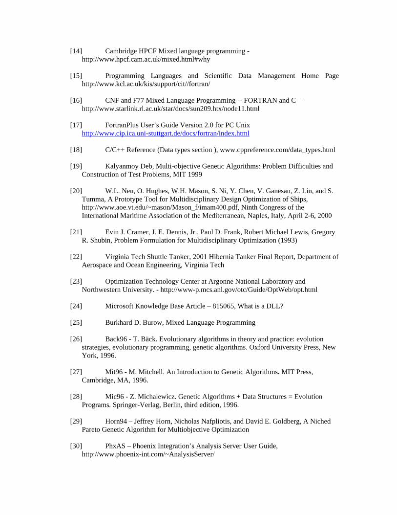
[14] Cambridge HPCF Mixed language programming - http://www.hpcf.cam.ac.uk/mixed.html#why
[15] Programming Languages and Scientific Data Management Home Page
http://www.kcl.ac.uk/kis/support/cit//fortran/
[16] CNF and F77 Mixed Language Programming -- FORTRAN and C – http://www.starlink.rl.ac.uk/star/docs/sun209.htx/node11.html
[17] FortranPlus User’s Guide Version 2.0 for PC Unix
http://www.cip.ica.uni-stuttgart.de/docs/fortran/index.html
[18] C/C++ Reference (Data types section ), www.cppreference.com/data_types.html
[19] Kalyanmoy Deb, Multi-objective Genetic Algorithms: Problem Difficulties and Construction of Test Problems, MIT 1999
[20] W.L. Neu, O. Hughes, W.H. Mason, S. Ni, Y. Chen, V. Ganesan, Z. Lin, and S.
Tumma, A Prototype Tool for Multidisciplinary Design Optimization of Ships, http://www.aoe.vt.edu/~mason/Mason_f/imam400.pdf, Ninth Congress of the International Maritime Association of the Mediterranean, Naples, Italy, April 2-6, 2000
[21] Evin J. Cramer, J. E. Dennis, Jr., Paul D. Frank, Robert Michael Lewis, Gregory
R. Shubin, Problem Formulation for Multidisciplinary Optimization (1993)
[22] Virginia Tech Shuttle Tanker, 2001 Hibernia Tanker Final Report, Department of Aerospace and Ocean Engineering, Virginia Tech
[23] Optimization Technology Center at Argonne National Laboratory and
Northwestern University. - http://www-p.mcs.anl.gov/otc/Guide/OptWeb/opt.html
[24] Microsoft Knowledge Base Article – 815065, What is a DLL?
[25] Burkhard D. Burow, Mixed Language Programming
[26] Back96 - T. Bäck. Evolutionary algorithms in theory and practice: evolution strategies, evolutionary programming, genetic algorithms. Oxford University Press, New York, 1996.
[27] Mit96 - M. Mitchell. An Introduction to Genetic Algorithms. MIT Press,
Cambridge, MA, 1996.
[28] Mic96 - Z. Michalewicz. Genetic Algorithms + Data Structures = Evolution Programs. Springer-Verlag, Berlin, third edition, 1996.
[29] Horn94 – Jeffrey Horn, Nicholas Nafpliotis, and David E. Goldberg, A Niched
Pareto Genetic Algorithm for Multiobjective Optimization
[30] PhxAS – Phoenix Integration’s Analysis Server User Guide, http://www.phoenix-int.com/~AnalysisServer/

[31] PhxMC – Phoenix Integration’s ModelCenter User Guide for ModelCenter 5.0
Related Documents