Leonard Megatron ® Complete Water Temperature Control Systems Regulate water temperature for building hot water systems and other commercial, institutional and industrial applications. Complete Water Temperature Control System MEGATRON ® 6NB-LF

Welcome message from author
This document is posted to help you gain knowledge. Please leave a comment to let me know what you think about it! Share it to your friends and learn new things together.
Transcript
Leonard Megatron® Complete Water Temperature Control Systems
Regulate water temperature for building hot water systems and other commercial, institutional and industrial applications.
Complete Water Temperature Control System
MEGATRON® 6NB-LF
Complete Water Temperature Control System
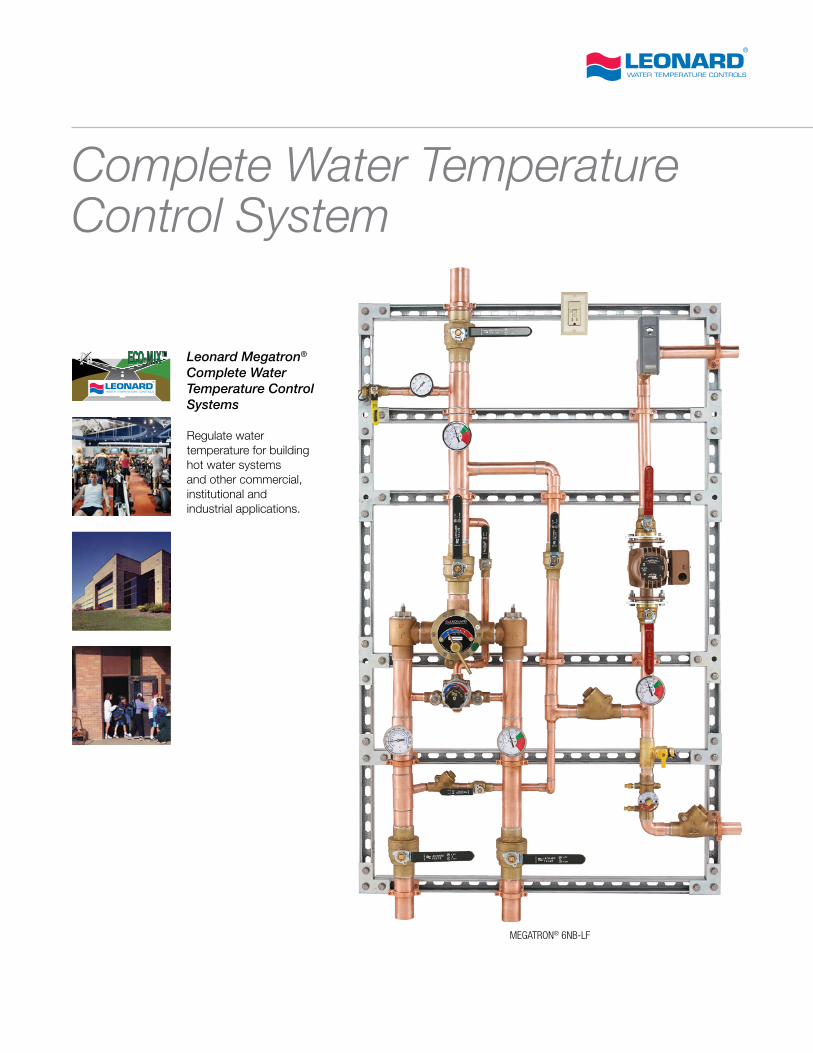
Leonard Megatron® Complete Water Temperature Control Systems
• Copper encapsulated thermostatic water mixing valves, DURA-trol® solid bi-metal thermostatic control and paraffin-based thermostatic control solutions
• Adjustable high temperature limit stops set for 120°F
• Mixed water capacity from 0.5-642 GPM (0.95-2430 l/min)
• Simple installation, reduced setup costs
• All bronze, brass and stainless steel construction
• System mounted on strut with return piping and circulator
• Factory-preassembled and tested as a complete control station
• Toll-free technical support
2
Water Temperature Bi-Metal Control System Specification
Sample Specification
________“ inlets, ________“ outlet, ________ return piping
________ GPM minimum flow capacity (see chart on page 5)
________ GPM maximum flow capacity @________ PSI system pressure drop
Large and small TYPE TM thermostatic water mixing valves
DURA-trol® solid bi-metal thermostats, color-coded dials, adjustable limit stops set for 120°F (49°C), integral check-stops
Tempered water line with thermometer and pressure gauge
Thermometers on inlets, outlet and return line
Circulator capable of ________ GPM @________ Ft. Head as specified by engineer
Aquastat and switch box (wiring by others)
Return piping balancing valve, drain valve
Check valves on return and bypass lines
Unit mounted on galvanized strut with cushioned clamps
Rough bronze finish
Factory-preassembled and pretested
All valve assemblies are ASSE 1017 Listed and 3rd Party certified as Lead Free
Selection Guide
Megatron® (Models) - (Options) - (Piping)
Models
1NB-LF 3/4” inlets, 1” outlet, 1-42GPM (3.7-159 l/min)
2NB-LF 3/4” inlets, 1” outlet, 1-72 GPM (3.7-272 l/min)
3NB-LF 1” inlets, 1-1/4” outlet, 1-84 GPM (3.7-318 l/min)
4NB-LF 1-1/4” inlets and outlet, 1-103 GPM (3.7-390 l/min)
5NB-LF 1-1/4” inlets, 1-1/2” outlet, 1-158 GPM (3.7-598 l/min)
6NB-LF 2” inlets and outlet, 1-214 GPM (3.7-810 l/min)
7NB-LF 2” inlets and outlet, 2-316 GPM (7.6-1196 l/min)
8NB-LF 3” inlets and outlet, 2-428 GPM (7.6-1620 l/min)
10NB-LF 4” inlets and outlet, 3-642 GPM (11.4-2430 l/min)
Options
BMSI Building Management System Interface
AL Audio visual alarm
FM Floor Mounted
FS Free Standing
Piping
M5 Method #5 piping for systems circulating over 8.0 GPM (see p. 4)
RP 1 1” Return line size (M5)
RP 1-1/4” 1-1/4” Return line size (M5)
RP 1-1/2” 1-1/2” Return line size (M5)
RP 2 2” Return line size (M5)
Standard Megatron® Systems – Piping Methods
Method 2 (up to 8.0 GPM) Models 1N, 2N, 3N, 4N
Method 5 (over 8.0 GPM) Models 5N, 6N, 7N, 8N, 10N
Megatron® 8NB-LF-BMSI-AL-TD-FM2-428 GPM (7.6-1620 l/min)
3” inlets/outlet, 1-1/2” return line
3
Models In Out
MinimumFlow GPM
PRESSURE DROP
5 10 15 20 25 30 35 40 45 50 PSI
L/MIN 0.3 0.7 1.0 1.4 1.7 2.1 2.4 2.8 3.1 3.4 BAR
1NB-LF*3/4" 1" 1.0 12 18 22 26 30 33 36 39 42 44 GPM
(19.1mm) (25.4mm) 3.7 45 68 83 98 114 125 136 148 159 167 L/MIN
2NB-LF*3/4" 1" 1.0 19 29 38 45 51 56 62 68 72 75 GPM
(19.1mm) (25.4mm) 3.7 72 110 144 170 193 212 235 257 272 284 L/MIN
3NB-LF*1" 1 1/4" 1.0 26 40 48 58 63 68 74 79 84 89 GPM
(25.4mm) (31.6mm) 3.7 98 151 182 220 238 257 280 299 318 337 L/MIN
4NB-LF*1 1/4" 1 1/4" 1.0 33 47 56 63 68 82 85 92 103 115 GPM
(31.6mm) (31.6mm) 3.7 125 178 212 238 257 310 322 348 390 435 L/MIN
5NB-LF*1 1/4" 1 1/2" 1.0 48 65 80 95 112 120 130 140 158 165 GPM
(31.6mm) (38.1mm) 3.7 182 246 303 360 424 454 492 530 598 625 L/MIN
6NB-LF*2" 2" 1.0 78 113 129 145 163 172 188 197 214 226 GPM
(50.8mm) (50.8mm) 3.7 295 428 488 549 617 651 712 746 810 856 L/MIN
7NB-LF*2" 2" 2.0 96 130 160 190 224 240 260 280 316 330 GPM
(50.8mm) (50.8mm) 7.6 363 492 606 719 848 908 984 1060 1196 1249 L/MIN
8NB-LF*3" 3" 2.0 156 226 258 290 326 344 376 394 428 452 GPM
(76.2mm) (76.2mm) 7.6 591 856 977 1098 1234 1302 1423 1491 1620 1711 L/MIN
10NB-LF*4" 4" 3.0 234 339 387 435 489 516 564 591 642 678 GPM
(102mm) (102mm) 11.4 886 1283 1465 1647 1851 1953 2135 2237 2430 2567 L/MIN
* Valve assemblies are ASSE Standard 1017 listed and are 3rd party certified as lead free
MAXIMUM FLOW CAPACITY
Models In Out
MinimumFlow GPM
PRESSURE DROP
5 10 15 20 25 30 35 40 45 50 PSI
L/MIN 0.3 0.7 1.0 1.4 1.7 2.1 2.4 2.8 3.1 3.4 BAR
270-LF**1/2" 1/2" 0.25 3.5 5.5 6.5 7.5 8.5 9.5 10.0 10.5 11 12 GPM
(12.7mm) (12.7mm) 0.95 13 21 25 28 32 36 38 40 42 45 L/MIN
370-LF**3/4" 3/4" 0.5 4.0 6.0 7.0 8.0 9.0 10.0 10.5 11.5 12.5 13 GPM
(19.1mm) (19.1mm) 1.9 15 23 27 30 34 38 40 43 47 49 L/MIN
XL-32-LF*3/4" 3/4" 1.0 11 16 20 22 24 26 28 30 32 33 GPM
(19.1mm) (19.1mm) 3.7 42 61 76 83 91 98 106 114 121 125 L/MIN
XL-82-LF*1" 1 1/4" 1.0 19 28 34 39 43 48 51 55 58 61 GPM
(25.4mm) (31.6mm) 3.7 72 106 129 148 163 182 193 208 219 231 L/MIN
XL-150-LF*1 1/4" 1 1/2" 3.0 44 61 74 86 95 103 110 117 124 130 GPM
(31.6mm) (38.1mm) 11.4 167 231 280 326 360 390 416 443 469 492 L/MIN
XL-200-SW-LF*2" 2" 5.0 69 96 117 135 148 163 174 188 198 208 GPM
(50.8mm) (50.8mm) 18.9 216 363 443 511 560 617 659 712 750 787 L/MIN
XL150-2P-LF*2" 2" 6.0 88 122 148 172 190 206 220 234 248 260 GPM
(50.8mm) (50.8mm) 22.7 333 462 560 651 719 780 833 886 939 984 L/MIN
* Valve assemblies are ASSE Standard 1017 listed** Valve assembly is ASSE Standards 1017 & 1070
listed all valve assemblies are 3rd party certified as lead free
MAXIMUM FLOW CAPACITY
Flow Capacities
CAUTION: All thermostatic water mixing valves have limitations. They will not provide the desired accuracy outside of their flow capacity range. Consult the above charts and make certain flow is greater than as shown above.
NOTE: Flow rates will vary depending on existing field conditions. Leonard Valve Company always recommends using CASPAK® sizing software for proper valve sizing and model number applications.
4
Water Temperature Paraffin Control System Specification
Sample Specification
________“ inlets, ________“ outlet, ________ return piping
________ GPM minimum flow capacity (see chart on page 5)
________ GPM maximum flow capacity @ ________ PSI system pressure drop
XL Series thermostatic water mixing valve, copper encapsulated paraffin-based technology, color coded dials, adjustable limit stops set for 120°F (49°C)
Tempered water line with thermometer and pressure gauge
Thermometers on inlets, outlet and test connection
Circulator capable of ________ GPM @ ________ Ft. Head as specified by engineer
Aquastat and switch box (wiring by others)
Return piping balancing valve, drain valve
Check valves on return and bypass lines
Unit mounted on galvanized strut with cushioned clamps
Rough bronze finish
Factory-preassembled and pretested
All valve assemblies are ASSE 1017 Listed and 3rd Party certified as Lead Free
Selection Guide
Megatron® (Models) - (Options) - (Piping)
Models
270-LF 0.25-11 GPM (0.95-42 l/min), 1/2” inlets and outlet, 1/2” return line
370-LF 0.25-12.5 GPM (0.95-47 l/min), 3/4” inlets and outlet, 3/4” return line
XL-32-LF 1-32 GPM (3.7-121 l/min), 3/4” inlets and outlet, 3/4” return line
XL-82-LF 1-58 GPM (3.7-219 l/min), 1” inlets, 1-1/4” outlet, 3/4” return line
XL-150-LF 3-124 GPM (11.4-469 l/min), 1-1/4” inlets, 1-1/2” outlet, 1” return line
XL-200-LF 5.0 - 198 GPM (18.9 - 750 l/min), 2” inlets and outlet, 1” return line
XL-150-2P-LF 6-248 GPM (22.7-939 l/min)), 2” inlets and outlet, 1-1/2” return line
XL-200-SW-2P-LF 5-198 GPM (18.9-750 l/min), 3” inlets and outlet, 1-1/2” return line
Options
BMSI Building Management System Interface
AL Audio visual alarm
FM Floor Mounted
FS Free Standing
Piping
RP 1 1” Return line size (M5)
RP 1-1/4” 1-1/4” Return line size (M5)
RP 1-1/2” 1-1/2” Return line size (M5)
RP 2 2” Return line size (M5)
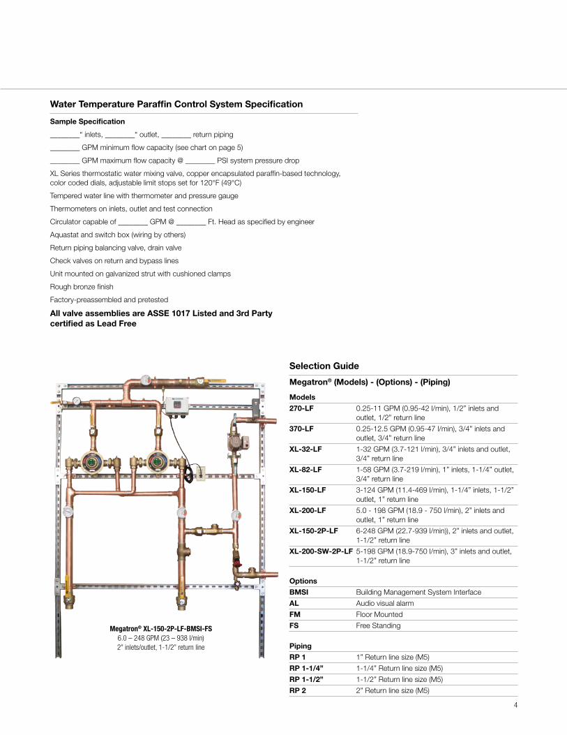
Megatron® XL-150-2P-LF-BMSI-FS6.0 – 248 GPM (23 – 938 l/min)2” inlets/outlet, 1-1/2” return line
5
Legend Required Piping Methods
140
60°c
Leonard
20 30
R
120
50
40
100
80
20
0
40
-10
10
60
0 °f
Kg/cm2 11
Leonard
Psi
4
6
80
140
160
1 20
10
8
100
40
20
2
60
60°c
Leonard
20 30
R
1 20
50
40
100
80
20
0
4 0
-10
10
60
0 °f
Asse1017
LeonardThermostatic
C H
-1020
0
40 10
0
120
100
°c
140°f
60
20 30
R
50
40
60 80
140
60°c
20 30
R
120
50
40
10080
20
0
40
-10
10
60
0 °f140
Leonard
Leonard
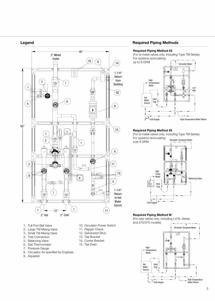
1. Full Port Ball Valve 2. Large TM Mixing Valve 3. Small TM Mixing Valve 4. Test Connection 5. Balancing Valve 6. Dial Thermometer 7. Pressure Gauge 8. Circulator-As specified by Engineer 9. Aquastat
10. Circulator Power Switch 11. Flapper Check 12. Galvanized Strut 13. Tee Bracket 14. Corner Bracket 15. Tee Drain
2" MixedOutlet
1-1/4"Returnfrom
Building
1-1/4"Returnto HotWaterSource
40"
62"
2" Hot 2" Cold12"
91014
8
1212
1 1 7
4 6
13
1
6
11
1 1
1
5
11
1
2
3
15
6
1
6
Required Piping Method W(For wax valves only, including LV/XL Series and 270/370 models)
100
120
30
R
80
20
50
60
Leonard40
40
0
20
-10
10
60
140°f0
°c
100
120
30
R
80
20
50
60
Leonard40
40
0
20
-10
10
60
140°f0
°c
100
120
30
R
80
20
50
60
Leonard40
40
0
20
-10
10
60
140°f0
°c
100
120
30
R
80
20
50
60
Leonard40
40
0
20
-10
10
60
140°f0
°c
Leonard
10
6
8
80100
160
140
120
20
2
40
4
60
PsiKg/cm 2 11
Domestic Tempered Water
HotWaterSource
Cold Supply
HeatTrap
HighTemperatureWater
High TemperatureWater Return
Required Piping Method #5(For bi-metal valves only, including Type TM Series)For systems recirculating over 8 GPM
kg/cm 2 11
LEONARD
psi
4
6
80
1 4 0
160
1 20
10
8
100
4 0
20
2
60
10
0
120
1 00
°C
1 40°F
60
20 30
LEONARD
50
40
60 80
LEONARDTHERMOSTATIC
C H
ASSE1017
-102 0
0
40
14 0
60°C
LEONARD
2030
12050
40
10 0
80
20
0
40
-10
10
60
0 °F
14 0
60°C
LEONARD
20 30
12050
40
1 00
80
2 0
0
40
-10
10
60
0 °F14 0
60°C
LEONARD
20 30
12050
40
10 0
80
20
0
40
-10
10
60
0 °F
Domestic Tempered Water
HighTemp.Water
Balancing Valve
Cold Supply
HeatTrap
HotWaterSource
0
20
40
°f0140
8060
120
100
60°c
-10
20
10
30
40
R
50
Nard
Leo
R.I.
U.S.
A.
Pe Tm
Us. Patent 770 & 3,061,195 3.152,760
Ston
Cran
Val
1017
Ve Co.
R
LeonardThermostatic
40
20
100
120
40
3020
R
0
10
60°c
°f
1400
-1050
160
8060
120
80
8
6
100
140
10
112Kg/cmPsi
60
4
40
2
20
120
60
20
°c
°f
°f0140
°c
-10
20
10
60
30
40
R
50
60 80
20
40
0
120
100
0140
20
40 10
60
0
-10
100
80
30
R
50
40
HC
Domestic Water
3/4" ARV
High Temperature Water ReturnCold Supply
HeatTrap
HotWaterSource
HighTemperatureWater
Leonard
Leonard
Leonard
Leonard
Leonard
1017
Asse
Required Piping Method #2(For bi-metal valves only, including Type TM Series)For systems recirculating up to 8 GPM
Note: All specifications are subject to change without notice!
1360 Elmwood AvenueCranston, RI 02910 USA800.222.1208t 401.461.1200f [email protected]
LV-116 03/15©2015 Leonard Valve Company. Printed in the U.S.A.
Options
BMSI
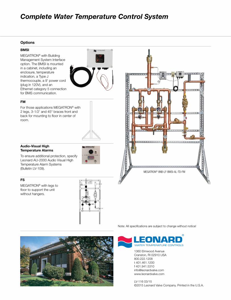
MEGATRON® with Building Management System Interface option. The BMSI is mounted in a cabinet, including an enclosure, temperature indication, a Type J thermocouple, a 9’ power cord (plug in 120V), and an Ethernet category 5 connection for BMS communication.
FM
For those applications MEGATRON® with 2 legs, 3-1/2’ and 45° braces front and back for mounting to floor in center of room.
Audio-Visual High Temperature Alarms
To ensure additional protection, specify Leonard AU-2000 Audio Visual High Temperature Alarm Systems (Bulletin LV-109).
FS
MEGATRON® with legs to floor to support the unit without hangers.
Complete Water Temperature Control System
MEGATRON® 8NB-LF-BMSI-AL-TD-FM
Related Documents