START Complete Machining Solutions THREADING TOOLS & INSERTS

Welcome message from author
This document is posted to help you gain knowledge. Please leave a comment to let me know what you think about it! Share it to your friends and learn new things together.
Transcript
START
Complete Machining Solutions THREADING TOOLS & INSERTS

ISCAR636
THR
EA
DIN
G
TABLE OF CONTENTS
Threading Inserts ................................................................................. 637
Selection Guide ........................................................................................................... 638
Insert Identification System .......................................................................................... 639
55° Partial Profile ......................................................................................................... 640
60° Partial Profile ......................................................................................................... 645
ISO Metric Full Profile .................................................................................................. 652
American UN Full Profile .............................................................................................. 657
Whitworth Full Profile ................................................................................................... 661
NPT/NPTF Full Profile .................................................................................................. 664
BSPT ........................................................................................................................... 667
STUB ACME ............................................................................................................... 669
ACME .......................................................................................................................... 670
UNJ ............................................................................................................................. 671
MJ ISO 5855 ............................................................................................................... 672
Trapeze DIN 103 .......................................................................................................... 673
SAGE DIN 513 ............................................................................................................ 675
American Buttress ....................................................................................................... 676
API Oil Threads ........................................................................................................... 677
Round DIN 405 ........................................................................................................... 680
Threading Tools .................................................................................... 684
Toolholder Identification System ................................................................................... 685
External Holders .......................................................................................................... 687
Threading Bars ............................................................................................................ 690
User Guide ............................................................................................ 696
637
THR
EA
DIN
G
THREADING INSERTS

ISCAR638
THR
EA
DIN
G
ISCAR638
THREADING SYSTEMS
B/M-TYPE U-TYPE REGULAR TYPE MULTI-TOOTH
Additional Threading Systems External
Internal
TIPI-Partial ProfileMinimum bore dia. 20 mm
GEPI-Partial Profile Minimum bore dia. 12.5 mm
Minimum bore dia. 2.4 mm
Mini-Bar
UMGR - Partial Profile 55º/60ºMinimum bore dia. 4 mm
Internal Internal
GIQR/L - Partial Profile 55º/60ºMinimum bore dia. 8.0 mm
Internal Internal
Main Types of Laydown Inserts
Partial Profile (TIP) Full Profile (TIP)
ExternalExternal External
639
THR
EA
DIN
G
639
INSERT IDENTIFICATION SYSTEM
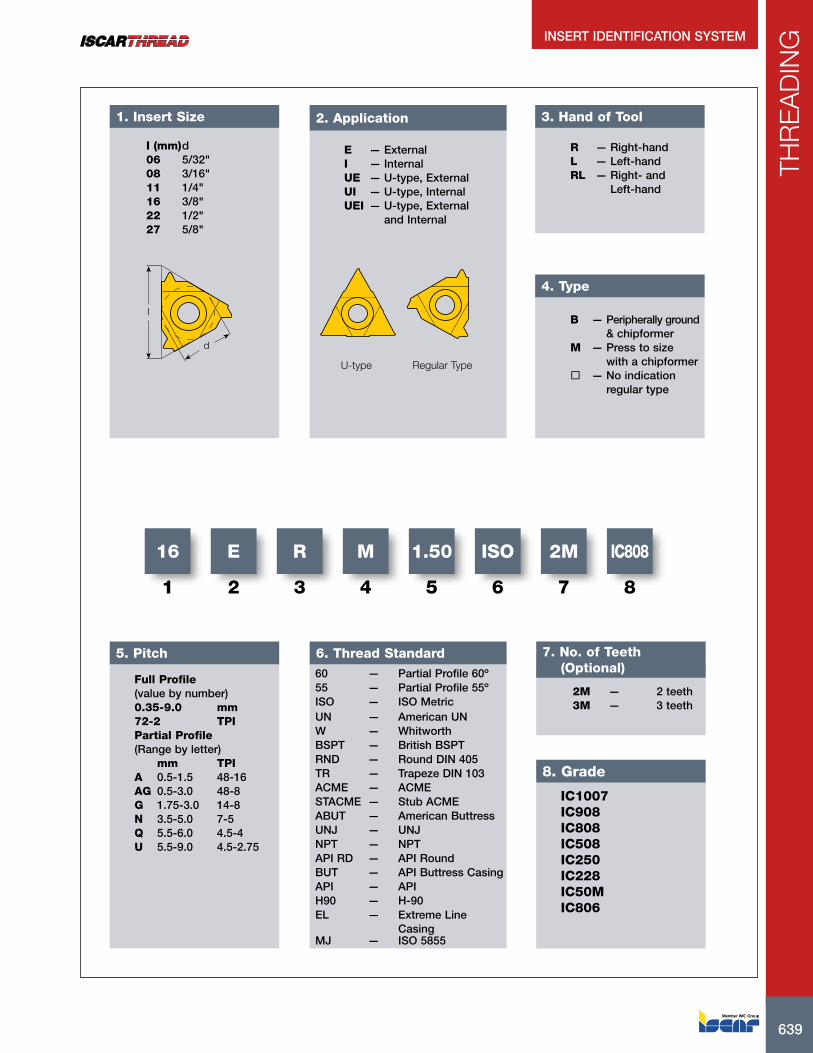
I (mm) d06 5/32"08 3/16"11 1/4"16 3/8"22 1/2"27 5/8"
1. Insert Size
d
I
E — ExternalI — InternalUE — U-type, ExternalUI — U-type, InternalUEI — U-type, External and Internal
2. Application
U-type Regular Type
3. Hand of Tool
R — Right-handL — Left-handRL — Right- and Left-hand
4. Type
B — Peripherally ground & chipformerM — Press to size with a chipformer — No indication regular type
5. Pitch
Full Profile(value by number)0.35-9.0 mm72-2 TPIPartial Profile(Range by letter) mm TPIA 0.5-1.5 48-16AG 0.5-3.0 48-8G 1.75-3.0 14-8N 3.5-5.0 7-5Q 5.5-6.0 4.5-4U 5.5-9.0 4.5-2.75
6. Thread Standard
16
1
E
2
R
3
M
4
1.50
5
ISO
6
IC808
8
2M
7
7. No. of Teeth (Optional)
2M — 2 teeth3M — 3 teeth
8. Grade
60 — Partial Profile 60º55 — Partial Profile 55ºISO — ISO MetricUN — American UNW — WhitworthBSPT — British BSPTRND — Round DIN 405TR — Trapeze DIN 103ACME — ACMESTACME — Stub ACMEABUT — American ButtressUNJ — UNJNPT — NPTAPI RD — API RoundBUT — API Buttress CasingAPI — APIH90 — H-90EL — Extreme Line
CasingMJ — ISO 5855
IC1007IC908IC808IC508IC250IC228IC50MIC806

ISCAR640
THR
EA
DIN
GPDX PDXRE
RE
INSLINSL
ICIC
PDY PDY
External right-hand shown
Dimensions Tough 1 Hard
Designation IC TPN(2) TPX(3) TPIX(4) TPIN(5) INSL RE PDY PDX IC22
8
IC50
M
IC25
0
IC80
8
IC90
8
IC10
07
11ER A 55 .250 .500 1.500 48.00 16.00 .433 .002 .03 .04 • •16ER/L A 55 .375 .500 1.500 48.00 16.00 .649 .002 .03 .04 • •16ER/L AG 55 .375 .500 3.000 48.00 8.00 .649 .003 .05 .07 • • • •16ERB AG 55 (1) .375 .500 3.000 48.00 8.00 .649 .003 .05 .07 •16ERM AG 55 (1) .375 .500 3.000 48.00 8.00 .649 .003 .05 .07 • • • • •16ER/L G 55 .375 1.750 3.000 14.00 8.00 .649 .008 .05 .07 • •16ERB G 55 (1) .375 1.750 3.000 14.00 8.00 .649 .009 .05 .07 •16ERM G 55 (1) .375 1.750 3.000 14.00 8.00 .649 .009 .05 .07 • • • •22ER/L N 55 .500 3.500 5.000 7.00 5.00 .866 .017 .07 .10 • •22UEIRL U 55 .500 5.500 8.000 4.50 3.25 .866 .024 .04 .43 • •27ER Q 55 .625 5.500 6.000 4.50 4.00 1.083 .024 .08 .11 • •27UEIRL U 55 .625 6.500 9.000 4.00 2.75 1.083 .032 .05 .54 •
• For insert identification system, see page 639 • For threading between walls use GRIP-type inserts TIP-WT, GEPI-WT, TIPI-WT • For detailed cutting data, see pages 696-697(1) With pressed chipformer (2) Thread pitch minimum (mm) (3) Thread pitch maximum (mm) (4) Threads per inch maximum (5) Threads per inch minimum
For tools, see pages: C#-SER/L (689) • SER/L (687)
ER/L-55°External Laydown Threading Inserts with a 55 ° Partial Profile for General Industry
55°
NUT
SCREW
PDX
PDY
PDY PDXRERE
lNSLlNSL
ICIC
U-Type
Internal left-hand shown
Dimensions Tough 1 Hard
Designation IC TPN(2) TPX(3) TPIX(4) TPIN(5) INSL RE PDY PDX IC22
8
IC92
8
IC50
M
IC25
0
IC50
8
IC80
8
IC90
8
IC10
0706IR/L A 55 .157 .500 1.250 48.00 20.00 .271 .002 .02 .02 •08IL A 55 .197 .500 1.500 48.00 16.00 .324 .002 .02 .03 • • •08UIRL U 55 .197 1.750 2.000 14.00 11.00 .324 .004 .04 .16 •11IR/L A 55 .250 .500 1.500 48.00 16.00 .433 .002 .03 .04 • • • •16IR A 55 .375 .500 1.500 48.00 16.00 .649 .002 .03 .04 • •16IR/L AG 55 .375 .500 3.000 48.00 8.00 .649 .003 .05 .07 • •16IRB AG 55 (1) .375 .500 3.000 48.00 8.00 .649 .003 .05 .07 •16IRM AG 55 (1) .375 .500 3.000 48.00 8.00 .649 .002 .05 .07 • • • •16IR/L G 55 .375 1.750 3.000 14.00 8.00 .649 .008 .05 .07 • • •16IRB G 55 (1) .375 1.750 3.000 14.00 8.00 .649 .009 .05 .07 •16IRM G 55 (1) .375 1.750 3.000 14.00 8.00 .649 .008 .05 .07 • • • •22IR N 55 .500 3.500 5.000 7.00 5.00 .866 .017 .07 .10 • • •27IR Q 55 .625 5.500 6.000 4.00 4.00 1.083 .024 .08 .11 •
• For insert identification system, see page 639 • For threading between walls use GRIP-type inserts TIP-WT, GEPI-WT, TIPI-WT. • For detailed cutting data, see pages 696-697(1) With pressed chipformer (2) Thread pitch minimum (mm) (3) Thread pitch maximum (mm) (4) Threads per inch maximum (5) Threads per inch minimum
For tools, see pages: MGSIR/L (694) • SIR/L (690)
IR/L-55°Internal Laydown Threading Inserts with a 55° Partial Profile for General Industry
55°
NUT
SCREW
641
THR
EA
DIN
G
Ø.67.138±.001
RE
PDX55°4°
Dimensions
Designation TPIX(1) TPIN(2) RE PDX IC10
08
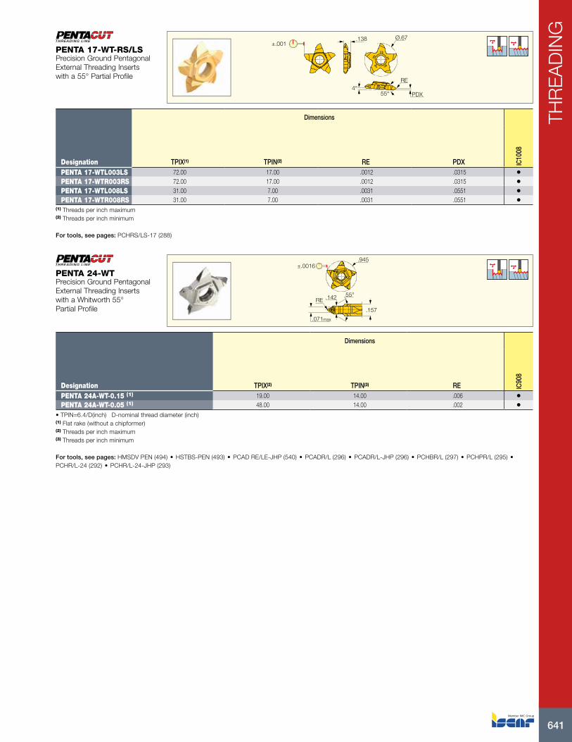
PENTA 17-WTL003LS 72.00 17.00 .0012 .0315 •PENTA 17-WTR003RS 72.00 17.00 .0012 .0315 •PENTA 17-WTL008LS 31.00 7.00 .0031 .0551 •PENTA 17-WTR008RS 31.00 7.00 .0031 .0551 •
(1) Threads per inch maximum (2) Threads per inch minimum
For tools, see pages: PCHRS/LS-17 (288)
PENTA 17-WT-RS/LSPrecision Ground Pentagonal External Threading Inserts with a 55° Partial Profile
.945
55°.142
.157
.071max
±.0016
RE
Dimensions
Designation TPIX(2) TPIN(3) RE IC90
8
PENTA 24A-WT-0.15 (1) 19.00 14.00 .006 •PENTA 24A-WT-0.05 (1) 48.00 14.00 .002 •
• TPIN=6.4/D(inch) D-nominal thread diameter (inch)(1) Flat rake (without a chipformer) (2) Threads per inch maximum (3) Threads per inch minimum
For tools, see pages: HMSDV PEN (494) • HSTBS-PEN (493) • PCAD RE/LE-JHP (540) • PCADR/L (296) • PCADR/L-JHP (296) • PCHBR/L (297) • PCHPR/L (295) • PCHR/L-24 (292) • PCHR/L-24-JHP (293)
PENTA 24-WTPrecision Ground Pentagonal External Threading Inserts with a Whitworth 55° Partial Profile

ISCAR642
THR
EA
DIN
G
.394 Ref.±.001
.114 Ref.
8˚
PNACW
RE BW
Dimensions Tough 1 Hard
Designation CW RE RETOL(1) PNA BW TPIX(2) TPN(3) TPIN(4) TPX(5) IC08
IC90
8
GEPI 2.5-WT0.05 .098 .002 .0012 55 .071 54.00 .470 10.00 2.540 • •• Toolholder seat needs to be modified according to insert profile to ensure clearance • Pitch max 0.167xD, TPI min D/6.0(1) Corner radius tolerance (+/-) (2) Threads per inch maximum (3) Thread pitch minimum (mm) (4) Threads per inch minimum (5) Thread pitch maximum (mm)
For tools, see pages: E-GEHIR / E-GHIR (343) • GEAIR/L (342) • GEHIMR/L (340) • GEHIMR/L-SC (340) • GEHIR/L (341) • GEHIR/L-SC (341) • GEHSR (377) • GEHSR/L-SL (377)
GEPI-WTPrecision Ground Double-Ended Threading Inserts with a 55° Partial Profile and a Chipformer for .453" Bore Diameter
.697 Ref.
55°
±.001
RE CW
TIP inserts are .063" longer than GIP in the same pocket
Dimensions Tough 1 Hard
Designation CW RE RETOL(2) TPIX(3) TPIN(4) TPX(5) IC08
IC90
8
TIP 2WT-0.05 (1) .094 .002 .0012 54.00 12.00 2.120 • •TIP 4WT-0.15 (1) .157 .006 .0012 19.00 7.00 3.630 • •TIP 5WT-0.25 (1) .217 .010 .0012 12.00 6.00 4.230 •
• Toolholder seat needs to be modified according to insert profile to ensure clearance • Pitch max 0.187xD(1) TPIN(thread per inch minimum) = D/6.4 • D-Diameter of thread (inch) (2) Corner radius tolerance (+/-) (3) Threads per inch maximum (4) Threads per inch minimum (5) Thread pitch maximum (mm)
For tools, see pages: C#-GHDR/L (251) • CGHN 26-M (360) • CGHN 32-DGM (362) • CGHN 32-M (361) • CGHN-D (257) • CGHN-DG (258) • CGHN-S (257) • CGPAD (256) • CGPAD-JHP (256) • GHDR/L (short pocket) (251) • GHDR/L-JHP (short pocket) (252) • GHGR/L (253) • GHMPR/L (250) • GHMR/L (250) • GHSR/L (378) • GHSR/L-JHP-SL (379)
TIP-WTPrecision Ground Double-Ended Threading Inserts with a 55° Partial Profile and a Chipformer

643
THR
EA
DIN
G
.197
8°
55°
.618 Ref.
±.001
CWRE
Dimensions Tough 1 Hard
Designation CW RE RETOL(1) TPN(2) TPIX(3) TPIN(4) TPX(5) IC08
IC90
8
TIPI 3.4WT-0.10 .134 .004 .0012 .950 27.00 8.00 3.180 • •TIPI 5.4WT-0.20 .213 .008 .0012 1.670 15.00 5.00 5.100 •
• Toolholder seat needs to be modified according to insert profile to ensure clearance • Pitch max 0.187xD, TPI min D/5.25 D=Diameter of thread (pitch max<=CW) • For detailed cutting data, see pages 696-697(1) Corner radius tolerance (+/-) (2) Thread pitch minimum (mm) (3) Threads per inch maximum (4) Threads per inch minimum (5) Thread pitch maximum (mm)
For tools, see pages: GAIR/L (349) • GHIR-SC (W=.079-.138) (348)
TIPI-WTDouble-Ended Internal Threading Inserts with a 55° Partial Profile and a Chipformer for .787" Min. Bore Diameter
X
a
x
55°
CFWF
OHNPDX
DCONMS
OAL
PDX
HC
Right-hand shown
Dimensions
Designation DCONMS TPIX(1) TPIN(2) HC CF PDX WF a OHN(3) OAL DMIN IC22
8
PICCO R 005.5548-15 .197 48.00 24.00 .016 .002 .02 .075 .173 .591 1.181 .189 •PICCO R 006.5548-15 .236 48.00 24.00 .016 .002 .02 .091 .209 .591 1.181 .236 •PICCO R 006.5524-15 .236 24.00 16.00 .032 .005 .03 .091 .209 .591 1.181 .236 •PICCO R 007.5524-15 .276 24.00 16.00 .032 .005 .03 .110 .248 .591 1.181 .276 •
• All mini-bars have sharp corners • For detailed cutting data, see pages 696-697(1) Threads per inch maximum (2) Threads per inch minimum (3) Minimum overhang
PICCO-55°-ThreadInserts for 55° Internal Threading Profile

ISCAR644
THR
EA
DIN
G
.004
.031
WF
PNA
Right-hand shown
Dimensions
Designation WF PNA TPIX(1) TPIN(2) TPN(3) TPX(4) DMIN IC50
8
UMGR 4.0-A55 .106 55 48.00 18.00 .500 1.400 .205 •(1) Threads per inch maximum (2) Threads per inch minimum (3) Thread pitch minimum (mm) (4) Thread pitch maximum (mm)
For tools, see pages: MGUHR (Metric) (425)
UMGR-A55Mini Indexable Inserts with Whitworth Partial Profile for Threading in .205" and Larger Holes
LWF
PDPT
REPNA
Left-hand shown
Dimensions
Designation L RE PNA PDPT(1) WF DMIN TPN(2) TPIX(3) IC52
8
GIQR/L 8-WT-0.05 .306 .002 55 .059 .189 .315 .500 50.00 •GIQR/L 11-WT-0.05 .420 .002 55 .079 .264 .433 .500 50.00 •
• Can be used for thread milling by circular interpolation • TPI min D/5.9 • D-diameter of thread (pitch max<=W) • For cutting speed recommendations, see pages 696-697(1) Cutting depth maximum (2) Thread pitch minimum (mm) (3) Threads per inch maximum
For tools, see pages: MG (428) • MGCH (429)
GIQR/L-WTInternal Inserts with Whitworth Partial Profile for Threading in .31" and Larger Holes

645
THR
EA
DIN
G
PDXPDXRE RE
INSLINSL
ICIC
PDY PDY
External right-hand shown
Dimensions Tough 1 Hard
Designation IC TPN(2) TPX(3) TPIX(4) TPIN(5) INSL RE PDY PDX IC22
8
IC50
M
IC25
0
IC08
IC50
8
IC80
8
IC90
8
IC10
07
11ER/L A 60 .250 .500 1.500 48.00 16.00 .433 .002 .03 .04 •16EL A 60 .375 .500 1.500 48.00 16.00 .649 .002 .03 .04 • • • • • •16ERB A 60 (1) .375 .500 1.500 48.00 16.00 .649 .002 .03 .03 • •16ERM A 60 (1) .375 .500 1.500 48.00 16.00 .649 .002 .03 .04 • • • • •16ER/L AG 60 .375 .500 3.000 48.00 8.00 .649 .002 .05 .07 • • • • • • •16ERB AG 60 (1) .375 .500 3.000 48.00 8.00 .649 .002 .05 .07 •16ERM AG 60 (1) .375 .500 3.000 48.00 8.00 .649 .002 .05 .07 • • • • • •16ER/L G 60 .375 1.750 3.000 14.00 8.00 .649 .009 .05 .07 • • • •16ERB G 60 (1) .375 1.750 3.000 14.00 8.00 .649 .009 .05 .07 •16ERM G 60 (1) .375 1.750 3.000 14.00 8.00 .649 .007 .05 .07 • • • • •22ER/L N 60 .500 3.500 5.000 7.00 5.00 .866 .017 .07 .10 • • • • •22ERM N 60 (1) .500 3.500 5.000 7.00 5.00 .866 .013 .07 .10 • • • • •22UEIRL U 60 .500 5.500 8.000 4.50 3.25 .866 .011 .02 .02 • •27ER/L Q 60 .625 5.500 6.000 4.50 4.00 1.083 .025 .08 .12 • • • •27UEIRL U 60 .625 6.500 9.000 4.00 2.75 1.083 .011 .04 .54 • •
• For Insert Identification System, see page 639 • For threading between walls use GRIP-type inserts SCIR/L B/F -MTR/L, TIP-MT, GEPI-MT, TIPI-MT. • For technical information and detailed cutting data, see pages 696-706(1) With pressed chipformer (2) Thread pitch minimum (mm) (3) Thread pitch maximum (mm) (4) Threads per inch maximum (5) Threads per inch minimum
For tools, see pages: C#-SER/L (689) • SER/L (687)
ER/L-60°External Laydown Threading Inserts with a 60° Partial Profile for General Industry
NUT
SCREW
60°

ISCAR646
THR
EA
DIN
G
PDX
PDY
PDY PDXRERE
lNSLlNSL
ICIC
U-Type
Internal left-hand shown
Dimensions Tough 1 Hard
Designation IC TPN(2) TPX(3) TPIX(4) TPIN(5) INSL RE PDY PDX IC28
IC22
8
IC50
M
IC25
0
IC08
IC50
8
IC80
8
IC90
8
IC10
07
06IR/L A 60 .157 .500 1.250 48.00 20.00 .271 .002 .02 .02 • •06IRM A 60 (1) .157 .500 1.250 48.00 20.00 .271 .002 .02 .02 •08IL A 60 .197 .500 1.500 48.00 16.00 .324 .002 .02 .03 • • • •08IRM A 60 (1) .197 .500 1.500 48.00 16.00 .324 .002 .02 .03 • • • •08UIRL U 60 .197 1.750 2.000 14.00 11.00 .324 .004 .03 .16 •11IR/L A 60 .250 .500 1.500 48.00 16.00 .433 .002 .03 .04 • • • • • •11IRM A 60 (1) .250 .500 1.500 48.00 16.00 .433 .002 .03 .04 • • • •16IL A 60 .375 .500 1.500 48.00 16.00 .649 .002 .03 .03 • • • • •16IRB A 60 (1) .375 .500 1.500 48.00 16.00 .649 .002 .03 .03 •16IRM A 60 (1) .375 .500 1.500 48.00 16.00 .649 .002 .03 .04 • • • •16IR/L AG 60 .375 .500 3.000 48.00 8.00 .649 .002 .05 .07 • • • • • •16IRB AG 60 (1) .375 .500 3.000 48.00 8.00 .649 .001 .05 .07 •16IRM AG 60 (1) .375 .500 3.000 48.00 8.00 .649 .002 .05 .07 • • • • •16IR/L G 60 .375 1.750 3.000 14.00 8.00 .649 .005 .05 .07 • • • • •16IRB G 60 (1) .375 1.750 3.000 14.00 8.00 .649 .005 .05 .07 •16IRM G 60 (1) .375 1.750 3.000 14.00 8.00 .649 .004 .05 .07 • • • • •22IR/L N 60 .500 3.500 5.000 7.00 5.00 .866 .009 .07 .10 • • •22IRM N 60 (1) .500 3.500 5.000 7.00 5.00 .866 .007 .07 .10 • • • • •27IR/L Q 60 .625 5.500 6.000 4.50 4.00 1.083 .012 .08 .12 • • •
• For Insert Identification System, see page 639 • For technical information and detailed cutting data, see pages 696-706(1) With a pressed chipformer (2) Thread pitch minimum (mm) (3) Thread pitch maximum (mm) (4) Threads per inch maximum (5) Threads per inch minimum
For tools, see pages: MGSIR/L (694) • SIR/L (690)
IR/L-60°Internal Laydown Threading Inserts with a 60° Partial Profile for General Industry
60°
NUT
SCREW
Ø.67.138±.001
RE
PDX60°4°
Dimensions
Designation TPN(1) TPX(2) RE PDX IC10
08
PENTA 17-MTL003LS .300 1.750 .0012 .0315 •PENTA 17-MTR003RS .300 1.750 .0012 .0315 •PENTA 17-MTL008LS .700 3.500 .0031 .0551 •PENTA 17-MTR008RS .700 3.500 .0031 .0551 •
(1) Thread pitch minimum (mm) (2) Thread pitch maximum (mm)
For tools, see pages: PCHRS/LS-17 (288)
PENTA 17-MT-RS/LSPrecision Ground Pentagonal External Threading Inserts with a 60° Partial Profile

647
THR
EA
DIN
G
.945
55°.142
.157
.071max
±.0016
RE
Dimensions
Designation TPN(2) TPX(3) RE IC90
8
PENTA 24-MT-0.05 .500 1.750 .002 •PENTA 24A-MT-0.05 (1) .500 1.750 .002 •PENTA 24A-MT-0.15 1.250 1.750 .006 •
• TPX=0.175xD(1) Flat rake (without a chipformer) (2) Thread pitch minimum (mm) (3) Thread pitch maximum (mm)
For tools, see pages: HMSDV PEN (494) • HSTBS-PEN (493) • PCAD RE/LE-JHP (540) • PCADR/L (296) • PCADR/L-JHP (296) • PCHBR/L (297) • PCHPR/L (295) • PCHR/L-24 (292) • PCHR/L-24-JHP (293)
PENTA 24-MTPrecision Ground Pentagonal External Threading Inserts with a 60° Partial Profile
.866
.276
PDX60°
RE
Dimensions Tough 1 Hard
Designation RE PDX TPN(1) TPX(2) TPIX(3) TPIN(4) IC10
08
IC07
IC10
07
SCIL 22-MTL003 .001 .02 .300 .900 83.00 28.00 • • •SCIR 22-MTR003 .001 .02 .300 .900 83.00 28.00 • • •SCIL 22-MTR/L007 .003 .02 .700 1.100 36.00 23.00 • • •SCIR 22-MTR/L007 .003 .02 .700 1.100 36.00 23.00 • • •SCIL 22-MTL010 .004 .03 .900 1.700 28.00 15.00 • • •SCIR 22-MTR010 .004 .03 .900 1.700 28.00 15.00 • • •
• For detailed cutting data, see pages 696-697(1) Thread pitch minimum (mm) (2) Thread pitch maximum (mm) (3) Threads per inch maximum (4) Threads per inch minimum
For tools, see pages: SCHR/L-22BF (367) • SCHR/L-22BF-JHP (367)
SCIR/L-22-MTR/MTLThreading Inserts with a 60° Partial Profile
ISCAR648
THR
EA
DIN
G
MTR
MTL
.334
1.61HF.157
60°
RE
PDX
Dimensions
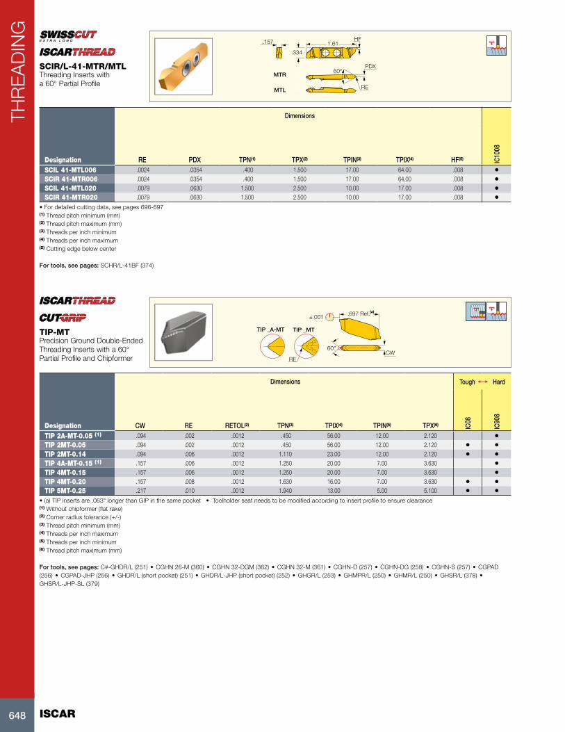
Designation RE PDX TPN(1) TPX(2) TPIN(3) TPIX(4) HF(5) IC10
08
SCIL 41-MTL006 .0024 .0354 .400 1.500 17.00 64.00 .008 •SCIR 41-MTR006 .0024 .0354 .400 1.500 17.00 64.00 .008 •SCIL 41-MTL020 .0079 .0630 1.500 2.500 10.00 17.00 .008 •SCIR 41-MTR020 .0079 .0630 1.500 2.500 10.00 17.00 .008 •
• For detailed cutting data, see pages 696-697(1) Thread pitch minimum (mm) (2) Thread pitch maximum (mm) (3) Threads per inch minimum (4) Threads per inch maximum (5) Cutting edge below center
For tools, see pages: SCHR/L-41BF (374)
SCIR/L-41-MTR/MTLThreading Inserts with a 60° Partial Profile
.697 Ref.(a)
CW
TIP _A-MT
60°
RE
±.001
TIP _MT
Dimensions Tough 1 Hard
Designation CW RE RETOL(2) TPN(3) TPIX(4) TPIN(5) TPX(6) IC08
IC90
8
TIP 2A-MT-0.05 (1) .094 .002 .0012 .450 56.00 12.00 2.120 •TIP 2MT-0.05 .094 .002 .0012 .450 56.00 12.00 2.120 • •TIP 2MT-0.14 .094 .006 .0012 1.110 23.00 12.00 2.120 • •TIP 4A-MT-0.15 (1) .157 .006 .0012 1.250 20.00 7.00 3.630 •TIP 4MT-0.15 .157 .006 .0012 1.250 20.00 7.00 3.630 •TIP 4MT-0.20 .157 .008 .0012 1.630 16.00 7.00 3.630 • •TIP 5MT-0.25 .217 .010 .0012 1.940 13.00 5.00 5.100 • •
• (a) TIP inserts are .063" longer than GIP in the same pocket • Toolholder seat needs to be modified according to insert profile to ensure clearance(1) Without chipformer (flat rake) (2) Corner radius tolerance (+/-) (3) Thread pitch minimum (mm) (4) Threads per inch maximum (5) Threads per inch minimum (6) Thread pitch maximum (mm)
For tools, see pages: C#-GHDR/L (251) • CGHN 26-M (360) • CGHN 32-DGM (362) • CGHN 32-M (361) • CGHN-D (257) • CGHN-DG (258) • CGHN-S (257) • CGPAD (256) • CGPAD-JHP (256) • GHDR/L (short pocket) (251) • GHDR/L-JHP (short pocket) (252) • GHGR/L (253) • GHMPR/L (250) • GHMR/L (250) • GHSR/L (378) • GHSR/L-JHP-SL (379)
TIP-MTPrecision Ground Double-Ended Threading Inserts with a 60° Partial Profile and Chipformer

649
THR
EA
DIN
G
.394 Ref.±.001
.114 Ref.
8˚
PNA CW
RE BW
Dimensions Tough 1 Hard
Designation CW RE RETOL(1) PNA BW TPN(2) TPIX(3) TPIN(4) TPX(5) IC08
IC90
8
GEPI 2.5-MT0.05 .098 .002 .0012 60 .071 .900 28.00 10.00 2.540 • •• Toolholder seat needs to be modified according to insert profile to ensure clearance • Pitch max 0.187xD, TPI min D/5.35 • D=Diameter of thread (pitch max<=CW)(1) Corner radius tolerance (+/-) (2) Thread pitch minimum (mm) (3) Threads per inch maximum (4) Threads per inch minimum (5) Thread pitch maximum (mm)
For tools, see pages: E-GEHIR / E-GHIR (343) • GEAIR/L (342) • GEHIMR/L (340) • GEHIMR/L-SC (340) • GEHIR/L (341) • GEHIR/L-SC (341) • GEHSR (377) • GEHSR/L-SL (377)
GEPI-MTPrecision Ground Internal Double-Ended Threading Inserts with a 60° Partial Profile for General Applications
.197
8°
CWRE
60°
±.001
.618 Ref
Dimensions Tough 1 Hard
Designation CW RE RETOL(1) TPN(2) TPIX(3) TPIN(4) TPX(5) IC08
IC90
8
TIPI 3.4MT-0.10 .134 .004 .0012 1.800 14.00 8.00 3.180 • •TIPI 5.4MT-0.20 .213 .008 .0012 3.190 8.00 5.00 5.100 • •
• Toolholder seat needs to be modified according to insert profile to ensure clearance. • Pitch max 0.205xD, TPI min D/4.8 • D=Diameter of thread (pitch max<=CW) • TIPI inserts are .063" longer than GIPI in the same pocket(1) Corner radius tolerance (+/-) (2) Thread pitch minimum (mm) (3) Threads per inch maximum (4) Threads per inch minimum (5) Thread pitch maximum (mm)
For tools, see pages: CGIN 26 (350) • GAIR/L (349) • GHIR-SC (W=.079-.138) (348) • GHIR/L (W=.078-.252) (347) • GHIR/L-C (W=.157-.252) (347)
TIPI-MTPrecision Ground Double-Ended Internal Threading Inserts with 60° Partial Profile and Chipformer for.787" Min. Bore Dia.

ISCAR650
THR
EA
DIN
G
.004
.031
WF
PNA
Right-hand shown
Dimensions
Designation PNA WF DMIN TPN(1) TPX(2) IC50
8
UMGR 4.0-A60 60 .106 .205 .500 1.250 •• For detailed cutting data, see pages 696-697(1) Thread pitch minimum (mm) (2) Thread pitch maximum (mm)
For tools, see pages: MGUHR (Metric) (425)
UMGR-A60Mini Indexable Inserts with a 60° Partial Profile for Threading in .205" and Larger Holes
WF30°
L
30°
RE.008RE
PDPT
Dimensions
Designation PDPT(1) RE L WF DMIN(2) TPN(3) TPX(4) IC90
8
MITR 8-MT2-0.1 .046 .0039 .226 .150 .394 1.500 2.000 •MITR 8-MT1-0.05 .048 .0020 .226 .150 .394 .750 1.250 •
(1) Cutting depth maximum (2) Minimum diameter (3) Thread pitch minimum (mm) (4) Thread pitch maximum (mm)
For tools, see pages: MIFHR (427)
MITR 8-MTInternal ISO Metric Threading Inserts for Partial Profile
LWF
PDPT
REPNA
Left-hand shown
Dimensions
Designation L RE PNA PDPT(1) WF DMIN(2) TPN(3) TPIX(4) IC52
8
GIQR/L 8-MT-0.05 .306 .002 60.0 .059 .189 .315 .900 28.00 •GIQR/L 11-MT-0.05 .420 .002 60.0 .079 .264 .433 .900 28.00 •
• Can be used for thread milling by circular interpolation • Pitch max 0.19xD • D-diameter of thread • For cutting speed recommendations, see pages 696-697(1) Cutting depth maximum (2) Minimum diameter (3) Thread pitch minimum (mm) (4) Threads per inch maximum
For tools, see pages: MG (428) • MGCH (429)
GIQR/L-MTInternal Threading Inserts with a 60° Partial Profile for Threading in .31" and Larger Holes
651
THR
EA
DIN
G
CF
WFa
OHN
PDX
DCONMS
OAL
x
PDX
60°
HC
X
Right-hand shown
Dimensions Tough 1 Hard
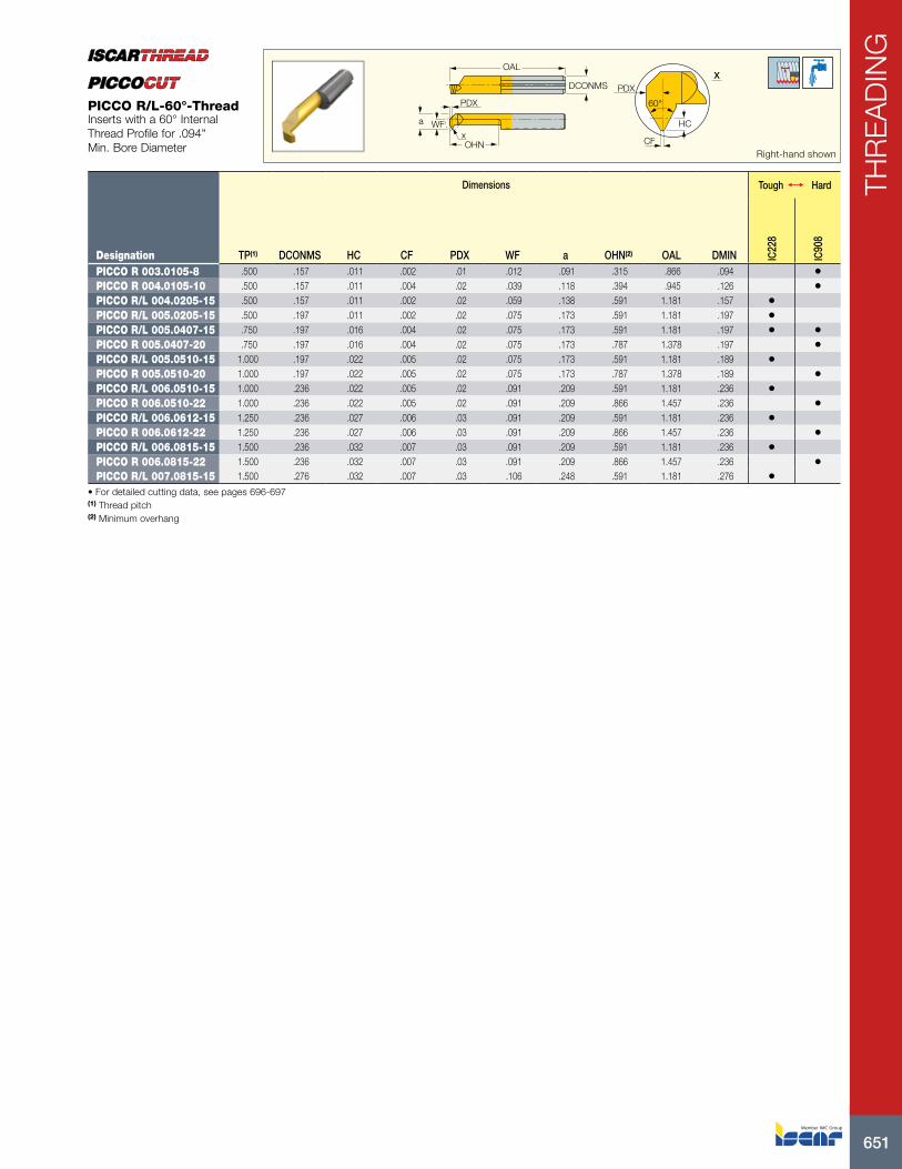
Designation TP(1) DCONMS HC CF PDX WF a OHN(2) OAL DMIN IC22
8
IC90
8
PICCO R 003.0105-8 .500 .157 .011 .002 .01 .012 .091 .315 .866 .094 •PICCO R 004.0105-10 .500 .157 .011 .004 .02 .039 .118 .394 .945 .126 •PICCO R/L 004.0205-15 .500 .157 .011 .002 .02 .059 .138 .591 1.181 .157 •PICCO R/L 005.0205-15 .500 .197 .011 .002 .02 .075 .173 .591 1.181 .197 •PICCO R/L 005.0407-15 .750 .197 .016 .004 .02 .075 .173 .591 1.181 .197 • •PICCO R 005.0407-20 .750 .197 .016 .004 .02 .075 .173 .787 1.378 .197 •PICCO R/L 005.0510-15 1.000 .197 .022 .005 .02 .075 .173 .591 1.181 .189 •PICCO R 005.0510-20 1.000 .197 .022 .005 .02 .075 .173 .787 1.378 .189 •PICCO R/L 006.0510-15 1.000 .236 .022 .005 .02 .091 .209 .591 1.181 .236 •PICCO R 006.0510-22 1.000 .236 .022 .005 .02 .091 .209 .866 1.457 .236 •PICCO R/L 006.0612-15 1.250 .236 .027 .006 .03 .091 .209 .591 1.181 .236 •PICCO R 006.0612-22 1.250 .236 .027 .006 .03 .091 .209 .866 1.457 .236 •PICCO R/L 006.0815-15 1.500 .236 .032 .007 .03 .091 .209 .591 1.181 .236 •PICCO R 006.0815-22 1.500 .236 .032 .007 .03 .091 .209 .866 1.457 .236 •PICCO R/L 007.0815-15 1.500 .276 .032 .007 .03 .106 .248 .591 1.181 .276 •
• For detailed cutting data, see pages 696-697(1) Thread pitch (2) Minimum overhang
PICCO R/L-60°-ThreadInserts with a 60° Internal Thread Profile for .094" Min. Bore Diameter

ISCAR652
THR
EA
DIN
G
ICIC
IC
INSL INSL INSLPDY PDY PDY
PDX
U-Type
PDXPDX
RE RE RE
External right-hand shown
Dimensions Tough 1 Hard
Designation IC TP(3) RE INSL PDY PDX CICT(4) IC22
8
IC50
M
IC25
0
IC08
IC50
8
IC80
8
IC90
8
IC10
07
11ER/L 0.35 ISO .250 .350 .002 .433 .03 .02 1 •11ER 0.40 ISO .250 .400 .002 .433 .03 .02 1 •11ER 0.45 ISO .250 .450 .002 .433 .03 .02 1 •11ER/L 0.50 ISO .250 .500 .002 .433 .02 .02 1 • •11ER 0.60 ISO .250 .600 .003 .433 .02 .02 1 •11ER 0.70 ISO .250 .700 .004 .433 .02 .02 1 •11ER/L 0.75 ISO .250 .750 .003 .433 .02 .02 1 •11ER 0.80 ISO .250 .800 .004 .433 .02 .02 1 •11ER/L 1.00 ISO .250 1.000 .005 .433 .03 .03 1 • •11ER 1.25 ISO .250 1.250 .006 .433 .03 .04 1 •11ER/L 1.50 ISO .250 1.500 .007 .433 .03 .04 1 • •11ER 1.75 ISO .250 1.750 .009 .433 .04 .03 1 •16EL 0.35 ISO .375 .350 .002 .649 .02 .02 1 •16ER/L 0.40 ISO .375 .400 .002 .649 .03 .02 1 •16ER 0.45 ISO .375 .450 .002 .649 .02 .02 1 •16EL 0.50 ISO .375 .500 .002 .649 .02 .02 1 • • • •16ER 0.60 ISO .375 .600 .004 .649 .02 .02 1 •16ER/L 0.70 ISO .375 .700 .004 .649 .02 .02 1 • • •16EL 0.75 ISO .375 .750 .004 .649 .02 .02 1 • • • •16ER 0.75 ISO 3M (1) .375 .750 .003 .649 .06 .07 3 •16ERM 0.75 ISO (2) .375 .750 .003 .649 .02 .02 1 • • •16ER/L 0.80 ISO .375 .800 .005 .649 .02 .02 1 • • •16ERB 0.80 ISO (2) .375 .800 .005 .649 .03 .03 1 •16EL 1.00 ISO .375 1.000 .005 .649 .03 .03 1 • • • • • •16ER 1.00 ISO 3M (1) .375 1.000 .003 .649 .07 .10 3 •16ERB 1.00 ISO (2) .375 1.000 .005 .649 .03 .03 1 •16ERM 1.00 ISO (2) .375 1.000 .004 .649 .03 .03 1 • • • • • •16ER/L 1.25 ISO .375 1.250 .006 .649 .03 .04 1 • • • •16ERB 1.25 ISO (2) .375 1.250 .006 .649 .03 .04 1 •16ERM 1.25 ISO (2) .375 1.250 .006 .649 .03 .04 1 • • • •16EL 1.50 ISO .375 1.500 .007 .649 .04 .05 1 • • • • • •16ER 1.50 ISO 2M (1) .375 1.500 .007 .649 .06 .09 2 • •16ERB 1.50 ISO (2) .375 1.500 .007 .649 .03 .04 1 •16ERM 1.50 ISO (2) .375 1.500 .007 .649 .03 .04 1 • • • • • •16ER/L 1.75 ISO .375 1.750 .009 .649 .04 .05 1 • • • • •16ERB 1.75 ISO (2) .375 1.750 .009 .649 .04 .05 1 •16ERM 1.75 ISO (2) .375 1.750 .008 .649 .04 .05 1 • • • •16ER/L 2.00 ISO .375 2.000 .010 .649 .04 .05 1 • • • • • •16ER 2.00 ISO 2M (1) .375 2.000 .004 .649 .07 .11 2 •16ERB 2.00 ISO (2) .375 2.000 .010 .649 .04 .05 1 •16ERM 2.00 ISO (2) .375 2.000 .009 .649 .04 .05 1 • • • • •16ER/L 2.50 ISO .375 2.500 .013 .649 .04 .06 1 • • • •16ERB 2.50 ISO .375 2.500 .013 .649 .04 .06 1 •16ERM 2.50 ISO (2) .375 2.500 .012 .649 .04 .06 1 • • • •16ER/L 3.00 ISO .375 3.000 .015 .649 .05 .06 1 • • • • • •16ERB 3.00 ISO (2) .375 3.000 .015 .649 .05 .06 1 •16ERM 3.00 ISO (2) .375 3.000 .015 .649 .05 .06 1 • • • • • •22ER 1.50 ISO 3M (1) .500 1.500 .003 .866 .09 .15 3 • •22ER 2.00 ISO 2M (1) .500 2.000 .010 .866 .08 .12 2 •22ER 2.00 ISO 3M (1) .500 2.000 .010 .866 .12 .20 3 • •22ER/L 3.50 ISO .500 3.500 .018 .866 .06 .09 1 • • •22ERM 3.50 ISO (2) .500 3.500 .019 .866 .06 .09 1 • •22ER/L 4.00 ISO .500 4.000 .020 .866 .06 .09 1 • • • •22ERM 4.00 ISO (2) .500 4.000 .020 .866 .06 .09 1 • •22ER 4.50 ISO .500 4.500 .023 .866 .06 .09 1 • •22ER/L 5.00 ISO .500 5.000 .026 .866 .07 .10 1 • •22UERL 5.50 ISO .500 5.500 .028 .866 .09 .43 1 •22ER/L 6.00 ISO .500 6.000 .031 .866 .08 .11 1 •22UERL 6.00 ISO .500 6.000 .031 .866 .10 .43 1 • •27ER 3.00 ISO 2M (1) .625 3.000 .015 1.083 .11 .18 2 •27ER 5.50 ISO .625 5.500 .028 1.083 .08 .11 1 •27EL 6.00 ISO .625 6.000 .031 1.083 .08 .11 1 • • •27UERL 8.00 ISO .625 8.000 .043 1.083 .09 .54 1 •
• For Insert Identification System, see page 639 • For threading between walls use GRIP-type inserts TIP-ISO class: 6G • For technical information and detailed cutting data, see pages 696-706 • For recommended number of passes for multi-tooth inserts see page 704(1) Multi-tooth (2) With pressed chipformer (3) Thread pitch (4) Number of teeth per corner For tools, see pages: C#-SER/L (689) • SER/L (687) • SER/L-JHP (688)
ER/L-ISOExternal ISO Metric (DIN13 12-1986 class: 6G) Laydown Threading Inserts for General Industry
60°1/4 TP
1/8 TP
NUT
SCREW
653
THR
EA
DIN
G
PDX PDX PDXRE RERE
PDY PDY
PDY
INSL INSL INSL
IC
IC
IC
U-Type
Internal left-hand shown
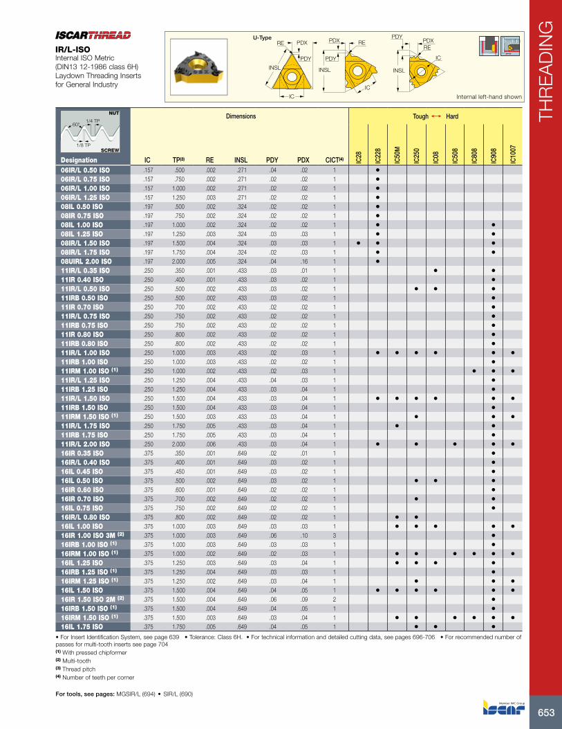
IR/L-ISOInternal ISO Metric (DIN13 12-1986 class 6H) Laydown Threading Inserts for General Industry
Dimensions Tough 1 Hard
Designation IC TP(3) RE INSL PDY PDX CICT(4) IC28
IC22
8
IC50
M
IC25
0
IC08
IC50
8
IC80
8
IC90
8
IC10
07
06IR/L 0.50 ISO .157 .500 .002 .271 .04 .02 1 •06IR/L 0.75 ISO .157 .750 .002 .271 .02 .02 1 •06IR/L 1.00 ISO .157 1.000 .002 .271 .02 .02 1 •06IR/L 1.25 ISO .157 1.250 .003 .271 .02 .02 1 •08IL 0.50 ISO .197 .500 .002 .324 .02 .02 1 •08IR 0.75 ISO .197 .750 .002 .324 .02 .02 1 •08IL 1.00 ISO .197 1.000 .002 .324 .02 .02 1 • •08IL 1.25 ISO .197 1.250 .003 .324 .03 .03 1 • •08IR/L 1.50 ISO .197 1.500 .004 .324 .03 .03 1 • • •08IR/L 1.75 ISO .197 1.750 .004 .324 .02 .03 1 • •08UIRL 2.00 ISO .197 2.000 .005 .324 .04 .16 1 •11IR/L 0.35 ISO .250 .350 .001 .433 .03 .01 1 • •11IR 0.40 ISO .250 .400 .001 .433 .03 .02 1 •11IR/L 0.50 ISO .250 .500 .002 .433 .03 .02 1 • • •11IRB 0.50 ISO .250 .500 .002 .433 .03 .02 1 •11IR 0.70 ISO .250 .700 .002 .433 .02 .02 1 •11IR/L 0.75 ISO .250 .750 .002 .433 .02 .02 1 •11IRB 0.75 ISO .250 .750 .002 .433 .02 .02 1 •11IR 0.80 ISO .250 .800 .002 .433 .02 .02 1 •11IRB 0.80 ISO .250 .800 .002 .433 .02 .02 1 •11IR/L 1.00 ISO .250 1.000 .003 .433 .02 .03 1 • • • • • •11IRB 1.00 ISO .250 1.000 .003 .433 .02 .02 1 •11IRM 1.00 ISO (1) .250 1.000 .002 .433 .02 .03 1 • • •11IR/L 1.25 ISO .250 1.250 .004 .433 .04 .03 1 •11IRB 1.25 ISO .250 1.250 .004 .433 .03 .04 1 •11IR/L 1.50 ISO .250 1.500 .004 .433 .03 .04 1 • • • • • •11IRB 1.50 ISO .250 1.500 .004 .433 .03 .04 1 •11IRM 1.50 ISO (1) .250 1.500 .003 .433 .03 .04 1 • • •11IR/L 1.75 ISO .250 1.750 .005 .433 .03 .04 1 • •11IRB 1.75 ISO .250 1.750 .005 .433 .03 .04 1 •11IR/L 2.00 ISO .250 2.000 .006 .433 .03 .04 1 • • • • •16IR 0.35 ISO .375 .350 .001 .649 .02 .01 1 •16IR/L 0.40 ISO .375 .400 .001 .649 .03 .02 1 •16IL 0.45 ISO .375 .450 .001 .649 .03 .02 1 •16IL 0.50 ISO .375 .500 .002 .649 .03 .02 1 • • •16IR 0.60 ISO .375 .600 .001 .649 .02 .02 1 •16IR 0.70 ISO .375 .700 .002 .649 .02 .02 1 • •16IL 0.75 ISO .375 .750 .002 .649 .02 .02 1 •16IR/L 0.80 ISO .375 .800 .002 .649 .02 .02 1 • •16IL 1.00 ISO .375 1.000 .003 .649 .03 .03 1 • • • • •16IR 1.00 ISO 3M (2) .375 1.000 .003 .649 .06 .10 3 •16IRB 1.00 ISO (1) .375 1.000 .003 .649 .03 .03 1 •16IRM 1.00 ISO (1) .375 1.000 .002 .649 .02 .03 1 • • • • • •16IL 1.25 ISO .375 1.250 .003 .649 .03 .04 1 • • • •16IRB 1.25 ISO (1) .375 1.250 .004 .649 .03 .03 1 •16IRM 1.25 ISO (1) .375 1.250 .002 .649 .03 .04 1 • • •16IL 1.50 ISO .375 1.500 .004 .649 .04 .05 1 • • • • • •16IR 1.50 ISO 2M (2) .375 1.500 .004 .649 .06 .09 2 •16IRB 1.50 ISO (1) .375 1.500 .004 .649 .04 .05 1 •16IRM 1.50 ISO (1) .375 1.500 .003 .649 .03 .04 1 • • • • • •16IL 1.75 ISO .375 1.750 .005 .649 .04 .05 1 • • •
• For Insert Identification System, see page 639 • Tolerance: Class 6H. • For technical information and detailed cutting data, see pages 696-706 • For recommended number of passes for multi-tooth inserts see page 704(1) With pressed chipformer (2) Multi-tooth (3) Thread pitch (4) Number of teeth per corner
For tools, see pages: MGSIR/L (694) • SIR/L (690)
60°1/4 TP
1/8 TP
NUT
SCREW
ISCAR654
THR
EA
DIN
G
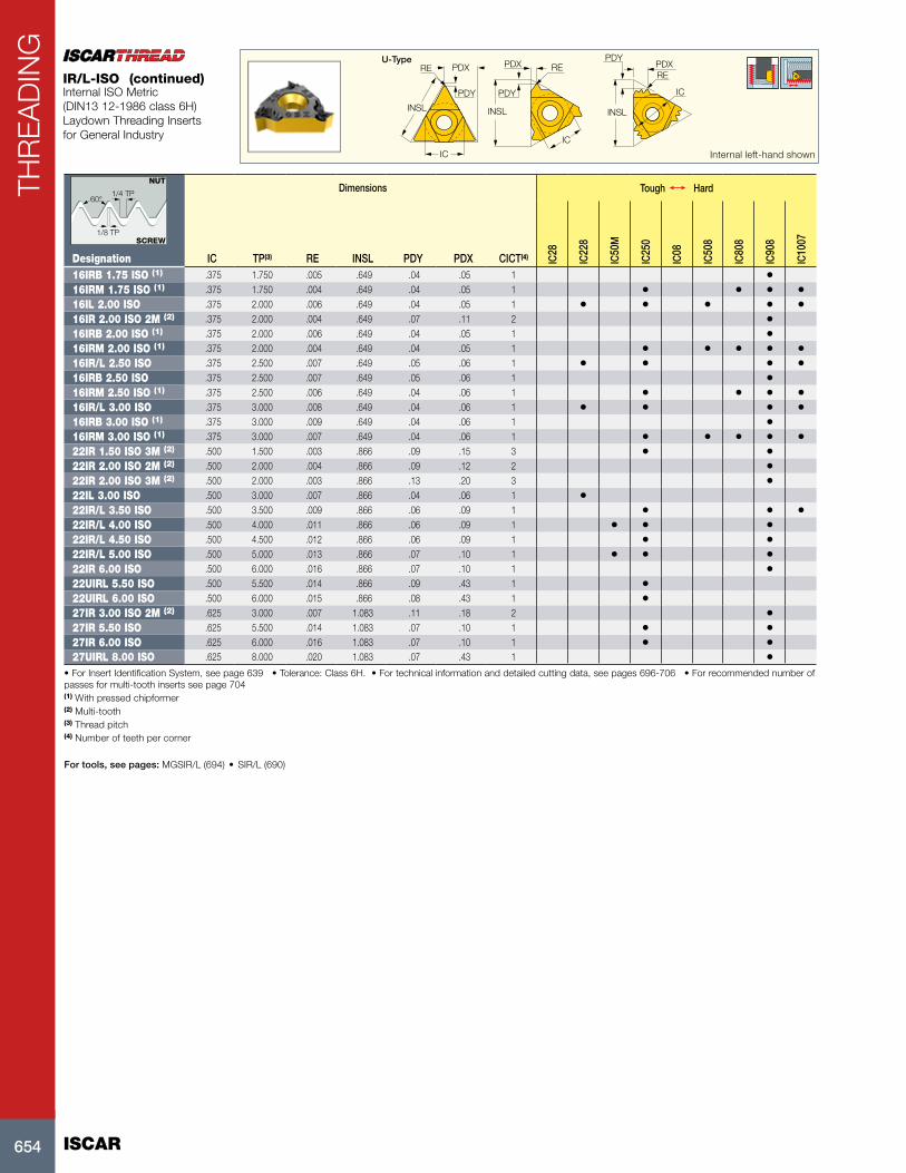
• For Insert Identification System, see page 639 • Tolerance: Class 6H. • For technical information and detailed cutting data, see pages 696-706 • For recommended number of passes for multi-tooth inserts see page 704(1) With pressed chipformer (2) Multi-tooth (3) Thread pitch (4) Number of teeth per corner
For tools, see pages: MGSIR/L (694) • SIR/L (690)
Dimensions Tough 1 Hard
Designation IC TP(3) RE INSL PDY PDX CICT(4) IC28
IC22
8
IC50
M
IC25
0
IC08
IC50
8
IC80
8
IC90
8
IC10
07
16IRB 1.75 ISO (1) .375 1.750 .005 .649 .04 .05 1 •16IRM 1.75 ISO (1) .375 1.750 .004 .649 .04 .05 1 • • • •16IL 2.00 ISO .375 2.000 .006 .649 .04 .05 1 • • • • •16IR 2.00 ISO 2M (2) .375 2.000 .004 .649 .07 .11 2 •16IRB 2.00 ISO (1) .375 2.000 .006 .649 .04 .05 1 •16IRM 2.00 ISO (1) .375 2.000 .004 .649 .04 .05 1 • • • • •16IR/L 2.50 ISO .375 2.500 .007 .649 .05 .06 1 • • • •16IRB 2.50 ISO .375 2.500 .007 .649 .05 .06 1 •16IRM 2.50 ISO (1) .375 2.500 .006 .649 .04 .06 1 • • • •16IR/L 3.00 ISO .375 3.000 .008 .649 .04 .06 1 • • • •16IRB 3.00 ISO (1) .375 3.000 .009 .649 .04 .06 1 •16IRM 3.00 ISO (1) .375 3.000 .007 .649 .04 .06 1 • • • • •22IR 1.50 ISO 3M (2) .500 1.500 .003 .866 .09 .15 3 • •22IR 2.00 ISO 2M (2) .500 2.000 .004 .866 .09 .12 2 •22IR 2.00 ISO 3M (2) .500 2.000 .003 .866 .13 .20 3 •22IL 3.00 ISO .500 3.000 .007 .866 .04 .06 1 •22IR/L 3.50 ISO .500 3.500 .009 .866 .06 .09 1 • • •22IR/L 4.00 ISO .500 4.000 .011 .866 .06 .09 1 • • •22IR/L 4.50 ISO .500 4.500 .012 .866 .06 .09 1 • •22IR/L 5.00 ISO .500 5.000 .013 .866 .07 .10 1 • • •22IR 6.00 ISO .500 6.000 .016 .866 .07 .10 1 •22UIRL 5.50 ISO .500 5.500 .014 .866 .09 .43 1 •22UIRL 6.00 ISO .500 6.000 .015 .866 .08 .43 1 •27IR 3.00 ISO 2M (2) .625 3.000 .007 1.083 .11 .18 2 •27IR 5.50 ISO .625 5.500 .014 1.083 .07 .10 1 • •27IR 6.00 ISO .625 6.000 .016 1.083 .07 .10 1 • •27UIRL 8.00 ISO .625 8.000 .020 1.083 .07 .43 1 •
PDX PDX PDXRE RERE
PDY PDY
PDY
INSL INSL INSL
IC
IC
IC
U-Type
Internal left-hand shown
IR/L-ISOInternal ISO Metric (DIN13 12-1986 class 6H) Laydown Threading Inserts for General Industry
60°1/4 TP
1/8 TP
NUT
SCREW
(continued)

655
THR
EA
DIN
G
X
WB
a
X
60°
CF
WF
OHNPDX
DCONMS
OAL
PDX
HC
Right-hand shown
Dimensions
Designation TP(1) DCONMS WF a OAL OHN(2) WB PDX HC CF DMIN IC90
8
PICCO R/L 105.0510-15 1.000 .197 .075 .173 1.181 .591 .130 .02 .021 .005 .189 •PICCO R/L 106.0612-15 1.250 .236 .091 .209 1.181 .591 .134 .03 .026 .006 .236 •PICCO R/L 106.0815-15 1.500 .236 .091 .209 1.181 .591 .134 .03 .032 .007 .236 •PICCO R/L 107.0815-15 1.500 .276 .110 .248 1.181 .591 .150 .03 .032 .007 .276 •
(1) Thread pitch (2) Minimum overhang
PICCO ISO Full ProfileInserts for ISO Standard Full Profile Thread
X
a
X
60°
WB CF
WF
OHNPDX
DCONMS
OAL
PDX
HC
Right-hand shown
Dimensions
Designation TP(1) DCONMS WF a OAL OHN(2) WB PDX HC CF DMIN IC90
8
PICCO R/L 104.0205-15 .500 .197 .059 .138 1.181 .591 .094 .02 .011 .002 .157 •PICCO R/L 105.0205-15 .500 .197 .075 .173 1.181 .591 .130 .02 .011 .002 .197 •PICCO R/L 105.0407-15 .750 .197 .075 .173 1.181 .591 .130 .02 .016 .004 .197 •PICCO R/L 106.0510-15 1.000 .236 .091 .209 1.181 .591 .134 .02 .021 .005 .236 •
(1) Thread pitch (2) Minimum overhang
PICCO ISO Full Profile FineInserts for ISO Fine Pitch Full Profile Thread
±.0016.945
.157.142
RE60°
Dimensions
Designation TP(1) RE IC90
8
PENTA 24-0.5-ISO .500 .003 •PENTA 24-0.75-ISO .750 .004 •PENTA 24-0.8-ISO .800 .005 •PENTA 24-1.0-ISO 1.000 .006 •PENTA 24-1.25-ISO 1.250 .007 •PENTA 24-1.5-ISO 1.500 .009 •PENTA 24-1.75-ISO 1.750 .010 •PENTA 24-2.0-ISO 2.000 .011 •
• DMIN(mm)=5.435xTP(1) Thread pitch
For tools, see pages: HMSDV PEN (494) • HSTBS-PEN (493) • PCAD RE/LE-JHP (540) • PCADR/L (296) • PCADR/L-JHP (296) • PCHBR/L (297) • PCHPR/L (295) • PCHR/L-24 (292) • PCHR/L-24-JHP (293)
PENTA 24-ISOPrecision Ground ISO Metric Full Profile Pentagonal External Threading Inserts with a Chipformer

ISCAR656
THR
EA
DIN
G.866
.276
.118
CDX
CWPDY
RE
Dimensions
Designation TP(1) CW CDX(2) RE PDY IC10
08
SCIR 22-MTR-0.3ISO .300 .039 .118 .001 .01 •SCIR 22-MTR-0.4ISO .400 .039 .118 .002 .01 •SCIR 22-MTR-0.5ISO .500 .039 .118 .002 .01 •SCIR 22-MTR-0.75ISO .750 .039 .118 .004 .02 •SCIR 22-MTR-1.0ISO 1.000 .059 .157 .006 .02 •SCIR 22-MTR-1.5ISO 1.500 .079 .157 .008 .03 •
(1) Thread pitch (2) Cutting depth maximum
For tools, see pages: SCHR/L-22BF (367) • SCHR/L-22BF-JHP (367)
SCIR-22-MTR-ISOPrecision Ground ISO Metric Full Profile Threading Inserts
.697 Ref.(a)±.001
60°RE
CW
Dimensions Tough 1 Hard
Designation TP(1) CW RE RETOL(2) IC08
IC90
8
TIP 2P0.5-ISO .500 .094 .003 .0012 • •TIP 2P0.75-ISO .750 .094 .004 .0012 • •TIP 2P0.8-ISO .800 .094 .005 .0012 • •TIP 2P1.0-ISO 1.000 .094 .006 .0012 • •TIP 2P1.25-ISO 1.250 .094 .007 .0012 • •TIP 2P1.5-ISO 1.500 .094 .009 .0012 • •TIP 2P1.75-ISO 1.750 .094 .010 .0012 • •TIP 4P2.0-ISO 2.000 .157 .011 .0012 • •TIP 4P2.5-ISO 2.500 .157 .014 .0020 • •TIP 4P3.0-ISO 3.000 .157 .017 .0020 •TIP 4P3.5-ISO 3.500 .157 .019 .0020 •TIP 5P4.0-ISO 4.000 .217 .022 .0020 •TIP 5P5.0-ISO 5.000 .217 .027 .0020 •
• (a) TIP inserts are .063" longer than GIP in the same pocket • Toolholder seat needs to be modified according to insert profile to ensure clearance(1) Thread pitch (2) Corner radius tolerance (+/-)
For tools, see pages: C#-GHDR/L (251) • CGHN-D (257) • CGHN-DG (258) • CGHN-S (257) • CGPAD (256) • CGPAD-JHP (256) • GHDR/L (short pocket) (251) • GHDR/L-JHP (short pocket) (252) • GHGR/L (253) • GHMPR/L (250) • GHMR/L (250) • GHSR/L (378) • GHSR/L-JHP-SL (379)
TIP-P-ISOPrecision Ground ISO Metric Full Profile Double-Ended External Threading Inserts with a Chipformer

657
THR
EA
DIN
G
RE REPDXPDX
PDYPDY
INSLINSL
IC
ICExternal right-hand shown
Dimensions Tough 1 Hard
Designation IC TPI(3) RE INSL PDY PDX CICT(4) IC22
8
IC50
M
IC25
0
IC08
IC50
8
IC80
8
IC90
8
IC10
07
11ER 44 UN .250 44.0 .002 .433 .02 .02 1 •11ER 32 UN .250 32.0 .004 .433 .02 .02 1 •11ER 28 UN .250 28.0 .004 .433 .02 .03 1 •11ER 24 UN .250 24.0 .005 .433 .03 .03 1 •11ER/L 20 UN .250 20.0 .006 .433 .03 .04 1 •11ER 18 UN .250 18.0 .007 .433 .03 .04 1 •11ER 16 UN .250 16.0 .007 .433 .04 .04 1 • • •16ER 72 UN .375 72.0 .002 .649 .03 .02 1 •16ER 56 UN .375 56.0 .002 .649 .03 .02 1 •16ER 48 UN .375 48.0 .002 .649 .02 .02 1 •16ER 40 UN .375 40.0 .002 .649 .02 .02 1 • •16ER/L 36 UN .375 36.0 .003 .649 .02 .02 1 •16ER/L 32 UN .375 32.0 .004 .649 .02 .02 1 • • •16ER/L 28 UN .375 28.0 .004 .649 .02 .03 1 • • •16ER 27 UN .375 27.0 .004 .649 .03 .03 1 •16ER/L 24 UN .375 24.0 .005 .649 .03 .03 1 • • •16ERB 24 UN (1) .375 24.0 .005 .649 .03 .03 1 •16ERM 24 UN (1) .375 24.0 .004 .649 .03 .03 1 • • •16EL 20 UN .375 20.0 .006 .649 .04 .03 1 • • • •16ERB 20 UN (1) .375 20.0 .006 .649 .03 .04 1 •16ERM 20 UN (1) .375 20.0 .006 .649 .03 .04 1 • • • •16ER/L 18 UN .375 18.0 .007 .649 .03 .03 1 • • • •16ERB 18 UN (1) .375 18.0 .007 .649 .03 .03 1 •16ERM 18 UN (1) .375 18.0 .006 .649 .03 .04 1 • • • •16ER/L 16 UN .375 16.0 .008 .649 .04 .05 1 • • • •16ER 16 UN 2M (2) .375 16.0 .004 .649 .06 .09 2 •16ERB 16 UN (1) .375 16.0 .008 .649 .04 .05 1 •16ERM 16 UN (1) .375 16.0 .007 .649 .04 .04 1 • • • •16ER/L 14 UN .375 14.0 .009 .649 .04 .05 1 • • • •16ER 14 UN 2M (2) .375 14.0 .004 .649 .06 .10 2 •16ERB 14 UN (1) .375 14.0 .009 .649 .04 .05 1 •16ERM 14 UN (1) .375 14.0 .009 .649 .04 .05 1 • • • •16ER/L 13 UN .375 13.0 .009 .649 .04 .05 1 • •16ERB 13 UN (1) .375 13.0 .010 .649 .04 .05 1 •16ERM 13 UN (1) .375 13.0 .009 .649 .04 .05 1 •16ER/L 12 UN .375 12.0 .011 .649 .04 .05 1 • • • •16ER 12 UN 2M (2) .375 12.0 .011 .649 .09 .13 2 •16ERB 12 UN (1) .375 12.0 .011 .649 .04 .05 1 •16ERM 12 UN (1) .375 12.0 .010 .649 .04 .06 1 • • • • •16ER 11.5 UN .375 11.5 .011 .649 .05 .06 1 •16ER/L 11 UN .375 11.0 .011 .649 .04 .06 1 • •16ERB 11 UN (1) .375 11.0 .011 .649 .04 .06 1 •16ER/L 10 UN .375 10.0 .013 .649 .04 .06 1 • • •16ERB 10 UN (1) .375 10.0 .013 .649 .04 .06 1 •16ER 9 UN .375 9.0 .014 .649 .05 .06 1 •16ERB 9 UN (1) .375 9.0 .014 .649 .05 .06 1 •16ER/L 8 UN .375 8.0 .016 .649 .05 .06 1 • • •16ERB 8 UN (1) .375 8.0 .016 .649 .05 .06 1 •16ERM 8 UN (1) .375 8.0 .016 .649 .05 .06 1 • • •22ER 12 UN 2M (2) .500 12.0 .011 .866 .09 .13 2 •22ER 12 UN 3M (2) .500 12.0 .011 .866 .13 .20 3 • •22ER 7 UN .500 7.0 .018 .866 .06 .09 1 •22ER 6 UN .500 6.0 .022 .866 .06 .09 1 •22ER 5 UN .500 5.0 .026 .866 .07 .10 1 • • •27ER 8 UN 2M (2) .625 8.0 .016 1.083 .12 .19 2 •27ER 4.5 UN .625 4.5 .030 1.083 .07 .11 1 •27ER 4 UN .625 4.0 .033 1.083 .03 .03 1 • • •
• For Insert Identification System, see page 639 • Tolerance: Class 2A • For threading between walls use GRIP-type insert TIP-UN • For technical information and detailed cutting data, see pages 696-706 • For recommended number of passes for multi-tooth inserts see page 704(1) With pressed chipformer. (2) Multi-tooth (3) Threads per inch (4) Number of teeth per corner
For tools, see pages: C#-SER/L (689) • SER/L (687) • SER/L-JHP (688)
ER/L-UNExternal American UN Full Profile (UN, UNC, UNF, UNEF) Laydown Threading Inserts for General Industry
60° 1/4 TP
1/8 TP
NUT
SCREW

ISCAR658
THR
EA
DIN
G
Dimensions Tough 1 Hard
Designation IC TPI(3) RE INSL PDY PDX CICT(4) IC22
8
IC92
8
IC50
M
IC25
0
IC08
IC50
8
IC80
8
IC90
8
IC10
07
06IR 32 UN .157 32.0 .002 .271 .03 .02 1 •06IR/L 24 UN .157 24.0 .002 .271 .03 .02 1 •06IR 20 UN .157 20.0 .004 .271 .02 .02 1 •06IR/L 18 UN .157 18.0 .003 .271 .02 .03 1 •08IR 32 UN .197 32.0 .002 .324 .02 .02 1 •08IR/L 28 UN .197 28.0 .002 .324 .02 .02 1 •08IL 24 UN .197 24.0 .002 .324 .02 .02 1 •08IR/L 20 UN .197 20.0 .003 .324 .03 .03 1 •08IR 18 UN .197 18.0 .003 .324 .03 .03 1 •08IR 16 UN .197 16.0 .004 .324 .02 .03 1 •08IR 14 UN .197 14.0 .004 .324 .02 .03 1 • •08UIRL 13 UN .197 13.0 .004 .324 .04 .16 1 •08UIRL 12 UN .197 12.0 .004 .324 .04 .16 1 •08UIRL 11 UN .197 11.0 .004 .324 .04 .16 1 •11IR/L 32 UN .250 32.0 .002 .433 .02 .02 1 •11IRB 32 UN .250 32.0 .002 .433 .02 .02 1 •11IR/L 28 UN .250 28.0 .002 .433 .02 .03 1 •11IRB 28 UN .250 28.0 .002 .433 .02 .02 1 •11IR/L 24 UN .250 24.0 .003 .433 .03 .03 1 •11IRB 24 UN .250 24.0 .003 .433 .02 .02 1 •11IR/L 20 UN .250 20.0 .004 .433 .03 .04 1 •11IRB 20 UN .250 20.0 .004 .433 .03 .04 1 •11IR/L 18 UN .250 18.0 .004 .433 .04 .04 1 • • •11IRB 18 UN .250 18.0 .004 .433 .04 .04 1 •11IR/L 16 UN .250 16.0 .004 .433 .04 .04 1 • •11IRB 16 UN .250 16.0 .004 .433 .04 .04 1 •11IR/L 14 UN .250 14.0 .004 .433 .04 .04 1 • •11IRB 14 UN .250 14.0 .005 .433 .04 .04 1 •11IR 12 UN .250 12.0 .005 .433 .04 .04 1 • •11IRB 12 UN .250 12.0 .005 .433 .04 .04 1 •11IR 11 UN .250 11.0 .006 .433 .03 .04 1 • •16IR 32 UN .375 32.0 .002 .649 .02 .02 1 • •16IL 28 UN .375 28.0 .002 .649 .02 .03 1 •16IR 24 UN .375 24.0 .003 .649 .03 .03 1 •16IRB 24 UN (1) .375 24.0 .003 .649 .03 .03 1 •16IL 20 UN .375 20.0 .002 .649 .03 .04 1 • • • •16IRB 20 UN (1) .375 20.0 .003 .649 .03 .03 1 •16IRM 20 UN (1) .375 20.0 .002 .649 .03 .04 1 • •16IL 18 UN .375 18.0 .003 .649 .03 .03 1 • •16IRB 18 UN (1) .375 18.0 .003 .649 .03 .03 1 •16IRM 18 UN (1) .375 18.0 .003 .649 .03 .04 1 • •16IL 16 UN .375 16.0 .004 .649 .04 .05 1 • •16IR 16 UN 2M (2) .375 16.0 .004 .649 .06 .09 2 • •16IRB 16 UN (1) .375 16.0 .004 .649 .04 .05 1 •16IRM 16 UN (1) .375 16.0 .004 .649 .04 .04 1 • • •16IL 14 UN .375 14.0 .005 .649 .04 .05 1 •16IRB 14 UN (1) .375 14.0 .005 .649 .04 .05 1 •
PDXPDX
PDX
IC
IC
IC
RE RERE
PDY
PDYPDY
lNSL lNSL lNSL
U-Type
Internal left-hand shown
IR/L-UNInternal American UN Full Profile (UN, UNC, UNF, UNEF) Laydown Threading Inserts for General Industry
60° 1/4 TP
1/8 TP
NUT
SCREW
• For Insert Identification System, see page 639 • Tolerance: class 2B,ANSI B1, 3M-1986. • For technical information and detailed cutting data, see pages 696-706 • For recommended number of passes for multi-tooth inserts see page 704(1) With pressed chipformer (2) Multi-tooth (3) Threads per inch (4) Number of teeth per corner
For tools, see pages: MGSIR/L (694) • SIR/L (690)

659
THR
EA
DIN
G
Dimensions Tough 1 Hard
Designation IC TPI(3) RE INSL PDY PDX CICT(4) IC22
8
IC92
8
IC50
M
IC25
0
IC08
IC50
8
IC80
8
IC90
8
IC10
07
16IRM 14 UN (1) .375 14.0 .004 .649 .04 .05 1 • • • •16IR/L 12 UN .375 12.0 .005 .649 .04 .04 1 • • • •16IRB 12 UN (1) .375 12.0 .005 .649 .04 .05 1 •16IRM 12 UN (1) .375 12.0 .005 .649 .04 .06 1 • • • •16IR 11.5 UN .375 11.5 .006 .649 .04 .04 1 •16IR 11 UN .375 11.0 .006 .649 .04 .04 1 •16IR/L 10 UN .375 10.0 .006 .649 .04 .06 1 • •16IRB 10 UN (1) .375 10.0 .006 .649 .04 .06 1 •16IR 9 UN .375 9.0 .007 .649 .05 .07 1 •16IR/L 8 UN .375 8.0 .009 .649 .04 .06 1 • • •16IRB 8 UN (1) .375 8.0 .009 .649 .04 .06 1 •16IRM 8 UN (1) .375 8.0 .008 .649 .04 .06 1 • • • •22IR 16 UN 3M (2) .500 16.0 .003 .866 .10 .16 3 •22IR 12 UN 2M (2) .500 12.0 .004 .866 .09 .13 2 •22IR 12 UN 3M (2) .500 12.0 .003 .866 .13 .20 3 •22IR/L 7 UN .500 7.0 .009 .866 .06 .09 1 • •22IR 6 UN .500 6.0 .010 .866 .06 .09 1 •22IR 5 UN .500 5.0 .013 .866 .06 .09 1 • •27IR 8 UN 2M (2) .625 8.0 .007 1.083 .12 .19 2 •27IR 4.5 UN .625 4.5 .014 1.083 .07 .09 1 •27IR 4 UN .625 4.0 .017 1.083 .07 .10 1 •
PDXPDX
PDX
IC
IC
IC
RE RERE
PDY
PDYPDY
lNSL lNSL lNSL
U-Type
Internal left-hand shown
IR/L-UNInternal American UN Full Profile (UN, UNC, UNF, UNEF) Laydown Threading Inserts for General Industry
60° 1/4 TP
1/8 TP
NUT
SCREW
• For Insert Identification System, see page 639 • Tolerance: class 2B,ANSI B1, 3M-1986. • For technical information and detailed cutting data, see pages 696-706 • For recommended number of passes for multi-tooth inserts see page 704(1) With pressed chipformer (2) Multi-tooth (3) Threads per inch (4) Number of teeth per corner
For tools, see pages: MGSIR/L (694) • SIR/L (690)
(continued)
ISCAR660
THR
EA
DIN
G±.0016
.945
.157.142
RE60°
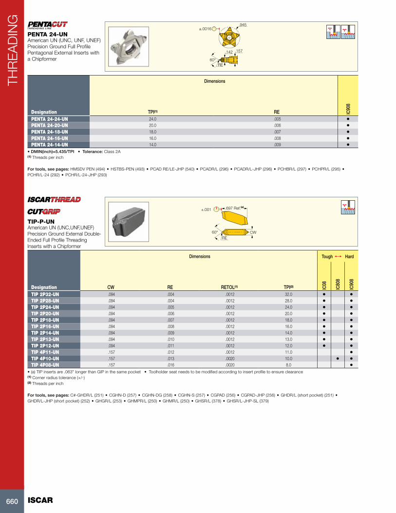
Dimensions
Designation TPI(1) RE IC90
8
PENTA 24-24-UN 24.0 .005 •PENTA 24-20-UN 20.0 .006 •PENTA 24-18-UN 18.0 .007 •PENTA 24-16-UN 16.0 .008 •PENTA 24-14-UN 14.0 .009 •
• DMIN(inch)=5.435/TPI • Tolerance: Class 2A(1) Threads per inch
For tools, see pages: HMSDV PEN (494) • HSTBS-PEN (493) • PCAD RE/LE-JHP (540) • PCADR/L (296) • PCADR/L-JHP (296) • PCHBR/L (297) • PCHPR/L (295) • PCHR/L-24 (292) • PCHR/L-24-JHP (293)
PENTA 24-UNAmerican UN (UNC, UNF, UNEF) Precision Ground Full Profile Pentagonal External Inserts with a Chipformer
.697 Ref.(a)±.001
CW60°RE
Dimensions Tough 1 Hard
Designation CW RE RETOL(1) TPI(2) IC08
IC80
8
IC90
8
TIP 2P32-UN .094 .004 .0012 32.0 • •TIP 2P28-UN .094 .004 .0012 28.0 • •TIP 2P24-UN .094 .005 .0012 24.0 • •TIP 2P20-UN .094 .006 .0012 20.0 • •TIP 2P18-UN .094 .007 .0012 18.0 • •TIP 2P16-UN .094 .008 .0012 16.0 • •TIP 2P14-UN .094 .009 .0012 14.0 • •TIP 2P13-UN .094 .010 .0012 13.0 • •TIP 2P12-UN .094 .011 .0012 12.0 • •TIP 4P11-UN .157 .012 .0012 11.0 •TIP 4P10-UN .157 .013 .0020 10.0 • •TIP 4P08-UN .157 .016 .0020 8.0 •
• (a) TIP inserts are .063" longer than GIP in the same pocket • Toolholder seat needs to be modified according to insert profile to ensure clearance(1) Corner radius tolerance (+/-) (2) Threads per inch
For tools, see pages: C#-GHDR/L (251) • CGHN-D (257) • CGHN-DG (258) • CGHN-S (257) • CGPAD (256) • CGPAD-JHP (256) • GHDR/L (short pocket) (251) • GHDR/L-JHP (short pocket) (252) • GHGR/L (253) • GHMPR/L (250) • GHMR/L (250) • GHSR/L (378) • GHSR/L-JHP-SL (379)
TIP-P-UNAmerican UN (UNC,UNF,UNEF) Precision Ground External Double-Ended Full Profile Threading Inserts with a Chipformer

661
THR
EA
DIN
G
PDX PDX PDXRE RE
U-Type
RE
PDY PDY PDYINSL
INSL INSL
ICIC
IC
External right-hand shown
Dimensions Tough 1 Hard
Designation IC TPI(3) RE INSL PDY PDX CICT(4) IC22
8
IC50
M
IC25
0
IC08
IC50
8
IC80
8
IC90
8
IC10
07
11ER/L 19 W .250 19.0 .006 .433 .03 .04 1 •11ER 14 W .250 14.0 .008 .433 .04 .04 1 •16ER 32 W .375 32.0 .004 .649 .02 .02 1 •16ER 28 W .375 28.0 .004 .649 .02 .03 1 • • •16ER 26 W .375 26.0 .005 .649 .03 .03 1 •16ER 24 W .375 24.0 .006 .649 .03 .03 1 •16ER 22 W .375 22.0 .005 .649 .03 .04 1 •16ER 20 W .375 20.0 .006 .649 .03 .03 1 •16EL 19 W .375 19.0 .007 .649 .03 .03 1 • • • •16ERB 19 W (1) .375 19.0 .007 .649 .03 .03 1 •16ERM 19 W (1) .375 19.0 .006 .649 .03 .04 1 • • • • •16ER/L 18 W .375 18.0 .007 .649 .04 .05 1 • •16ER 16 W .375 16.0 .008 .649 .04 .05 1 •16ERB 16 W (1) .375 16.0 .008 .649 .04 .05 1 •16ERM 16 W (1) .375 16.0 .008 .649 .04 .04 1 • • • •16ER/L 14 W .375 14.0 .009 .649 .04 .05 1 • • •16ER 14 W 2M (2) .375 14.0 .008 .649 .07 .11 2 •16ERB 14 W (1) .375 14.0 .009 .649 .04 .05 1 •16ERM 14 W (1) .375 14.0 .009 .649 .04 .05 1 • • • • •16ER/L 12 W .375 12.0 .011 .649 .05 .06 1 •16ER/L 11 W .375 11.0 .011 .649 .04 .06 1 • • • • • • •16ERB 11 W (1) .375 11.0 .011 .649 .04 .06 1 •16ERM 11 W (1) .375 11.0 .011 .649 .04 .06 1 • • • • •16ER 10 W .375 10.0 .013 .649 .04 .06 1 • •16ERB 10 W (1) .375 10.0 .013 .649 .04 .06 1 •16ER 9 W .375 9.0 .013 .649 .05 .07 1 •16ER/L 8 W .375 8.0 .015 .649 .05 .06 1 •22ER 14 W 3M (2) .500 14.0 .008 .866 .11 .18 3 •22ER 11 W 2M (2) .500 11.0 .004 .866 .09 .13 2 •22ER 7 W .500 7.0 .018 .866 .06 .09 1 •22ER 6 W .500 6.0 .020 .866 .06 .09 1 •22ER 5 W .500 5.0 .026 .866 .07 .09 1 •27ER 4 W .625 4.0 .034 1.083 .08 .11 1 •27UEIRL 3.5 W .625 3.5 .037 1.083 .08 .54 1 •
• For Insert Identification System, see page 639 • For threading between walls use GRIP-type insert TIP-BSW • Tolerance: medium class • For technical information and detailed cutting data, see pages 696-706 • For recommended number of passes for multi-tooth inserts see page 704(1) With pressed chipformer (2) Multi-tooth (3) Threads per inch (4) Number of teeth per corner
For tools, see pages: C#-SER/L (689) • SER/L (687) • SER/L-JHP (688)
ER/L-WExternal Whitworth (BSW, BSF, BSP) B.S.84-1956 DIN 259 Medium Class Full Profile Laydown Threading Inserts
0.137TP
0.137TP55°
NUT
SCREW

ISCAR662
THR
EA
DIN
GRE RE RE
INSL INSL INSL
PDXPDY
PDY
PDYPDX
U-Type PDX
IC
ICIC Internal left-hand shown
Dimensions Tough 1 Hard
Designation IC TPI(3) RE INSL PDY PDX CICT(4) IC22
8
IC92
8
IC50
M
IC25
0
IC08
IC50
8
IC80
8
IC90
8
IC10
07
06IR 26 W .157 26.0 .004 .271 .03 .02 1 •08IR 28 W .197 28.0 .004 .324 .02 .02 1 •08IR 19 W .197 19.0 .006 .324 .02 .02 1 • • •08IR 18 W .197 18.0 .006 .324 .02 .03 1 •08IR 16 W .197 16.0 .007 .324 .02 .03 1 •11IR 36 W .250 36.0 .003 .433 .02 .02 1 •11IR 28 W .250 28.0 .004 .433 .02 .03 1 •11IRB 28 W .250 28.0 .004 .433 .02 .02 1 •11IR 26 W .250 26.0 .004 .433 .03 .03 1 •11IR/L 24 W .250 24.0 .004 .433 .03 .03 1 •11IRB 24 W .250 24.0 .004 .433 .02 .02 1 •11IR 20 W .250 20.0 .006 .433 .03 .04 1 • •11IRB 20 W .250 20.0 .006 .433 .03 .04 1 •11IR 19 W .250 19.0 .006 .433 .03 .04 1 • • •11IRB 19 W .250 19.0 .007 .433 .03 .04 1 •11IR/L 18 W .250 18.0 .006 .433 .03 .04 1 •11IRB 18 W .250 18.0 .007 .433 .04 .04 1 •11IR 16 W .250 16.0 .007 .433 .04 .04 1 •11IRB 16 W .250 16.0 .007 .433 .03 .04 1 •11IR/L 14 W .250 14.0 .009 .433 .04 .04 1 • • • • •11IRB 14 W .250 14.0 .009 .433 .04 .04 1 •16IR 32 W .375 32.0 .004 .649 .02 .02 1 •16IR 28 W .375 28.0 .004 .649 .02 .03 1 •16IR 26 W .375 26.0 .005 .649 .03 .03 1 •16IR 24 W .375 24.0 .004 .649 .03 .03 1 •16IR 22 W .375 22.0 .005 .649 .03 .04 1 •16IR/L 20 W .375 20.0 .006 .649 .03 .04 1 • •16IRM 20 W (1) .375 20.0 .006 .649 .03 .04 1 •16IR 19 W .375 19.0 .007 .649 .03 .03 1 • •16IRB 19 W (1) .375 19.0 .007 .649 .03 .03 1 •16IRM 19 W (1) .375 19.0 .006 .649 .03 .04 1 •16IL 18 W .375 18.0 .007 .649 .03 .03 1 •16IR 16 W .375 16.0 .008 .649 .04 .04 1 •16IRB 16 W (1) .375 16.0 .008 .649 .04 .05 1 •16IRM 16 W (1) .375 16.0 .007 .649 .04 .04 1 •16IL 14 W .375 14.0 .009 .649 .04 .05 1 • • • • •16IR 14 W 2M (2) .375 14.0 .007 .649 .07 .10 2 • •16IRB 14 W (1) .375 14.0 .009 .649 .04 .05 1 •16IRM 14 W (1) .375 14.0 .008 .649 .04 .05 1 • • • •16IR 12 W .375 12.0 .011 .649 .05 .06 1 •16IR/L 11 W .375 11.0 .011 .649 .04 .06 1 • • • • • •16IRB 11 W (1) .375 11.0 .011 .649 .04 .06 1 •16IRM 11 W (1) .375 11.0 .011 .649 .04 .06 1 • • • • •16IR 10 W .375 10.0 .013 .649 .04 .04 1 •16IRB 10 W (1) .375 10.0 .012 .649 .04 .06 1 •16IR 9 W .375 9.0 .013 .649 .05 .07 1 •16IR/L 8 W .375 8.0 .016 .649 .04 .04 1 • •22IR 14 W 3M (2) .500 14.0 .008 .866 .11 .18 3 •22IR 11 W 2M (2) .500 11.0 .004 .866 .09 .13 2 •22IR 7 W .500 7.0 .018 .866 .06 .09 1 •22IR 6 W .500 6.0 .020 .866 .06 .09 1 •22IR 5 W .500 5.0 .026 .866 .07 .09 1 •27IR 4.5 W .625 4.5 .029 1.083 .07 .10 1 •27IR 4 W .625 4.0 .032 1.083 .08 .11 1 •
• For Insert Identification System, see page 639 • Tolerance: medium class • For technical information and detailed cutting data, see pages 696-706 • For recommended number of passes for multi-tooth inserts see page 704(1) With pressed chipformer (2) Multi-tooth (3) Threads per inch (4) Number of teeth per corner
For tools, see pages: MGSIR/L (694) • SIR/L (690)
IR/L-WInternal Whitworth (BSW, BSF, BSP) B.S.84-1956 DIN 259 Medium Class Full Profile Laydown Threading Inserts
55°
0.137TP
0.137TPNUT
SCREW
663
THR
EA
DIN
G
±.0016.945
.157.142
RE55°
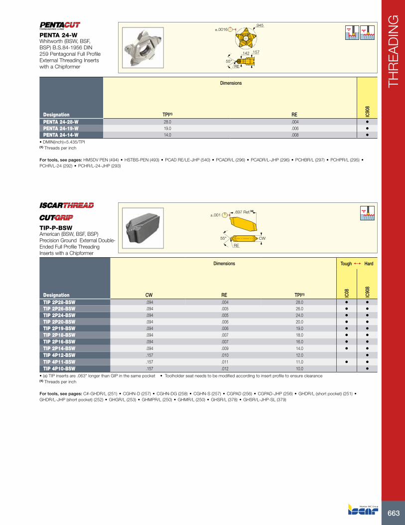
Dimensions
Designation TPI(1) RE IC90
8
PENTA 24-28-W 28.0 .004 •PENTA 24-19-W 19.0 .006 •PENTA 24-14-W 14.0 .008 •
• DMIN(inch)=5.435/TPI(1) Threads per inch
For tools, see pages: HMSDV PEN (494) • HSTBS-PEN (493) • PCAD RE/LE-JHP (540) • PCADR/L (296) • PCADR/L-JHP (296) • PCHBR/L (297) • PCHPR/L (295) • PCHR/L-24 (292) • PCHR/L-24-JHP (293)
PENTA 24-WWhitworth (BSW, BSF, BSP) B.S.84-1956 DIN 259 Pentagonal Full Profile External Threading Inserts with a Chipformer
.697 Ref.(a)
±.001
CW55°
RE
Dimensions Tough 1 Hard
Designation CW RE TPI(1) IC08
IC90
8
TIP 2P28-BSW .094 .004 28.0 • •TIP 2P26-BSW .094 .005 26.0 • •TIP 2P24-BSW .094 .005 24.0 • •TIP 2P20-BSW .094 .006 20.0 • •TIP 2P19-BSW .094 .006 19.0 • •TIP 2P18-BSW .094 .007 18.0 • •TIP 2P16-BSW .094 .007 16.0 • •TIP 2P14-BSW .094 .009 14.0 • •TIP 4P12-BSW .157 .010 12.0 •TIP 4P11-BSW .157 .011 11.0 • •TIP 4P10-BSW .157 .012 10.0 •
• (a) TIP inserts are .063" longer than GIP in the same pocket • Toolholder seat needs to be modified according to insert profile to ensure clearance(1) Threads per inch
For tools, see pages: C#-GHDR/L (251) • CGHN-D (257) • CGHN-DG (258) • CGHN-S (257) • CGPAD (256) • CGPAD-JHP (256) • GHDR/L (short pocket) (251) • GHDR/L-JHP (short pocket) (252) • GHGR/L (253) • GHMPR/L (250) • GHMR/L (250) • GHSR/L (378) • GHSR/L-JHP-SL (379)
TIP-P-BSWAmerican (BSW, BSF, BSP) Precision Ground External Double-Ended Full Profile Threading Inserts with a Chipformer
ISCAR664
THR
EA
DIN
G
REREPDX PDX
PDY PDYINSL INSL
IC
IC
External right-hand shown
Dimensions Tough 1 Hard
Designation IC TPI(3) RE INSL PDY PDX CICT(4) IC22
8
IC50
M
IC25
0
IC80
8
IC90
8
IC10
07
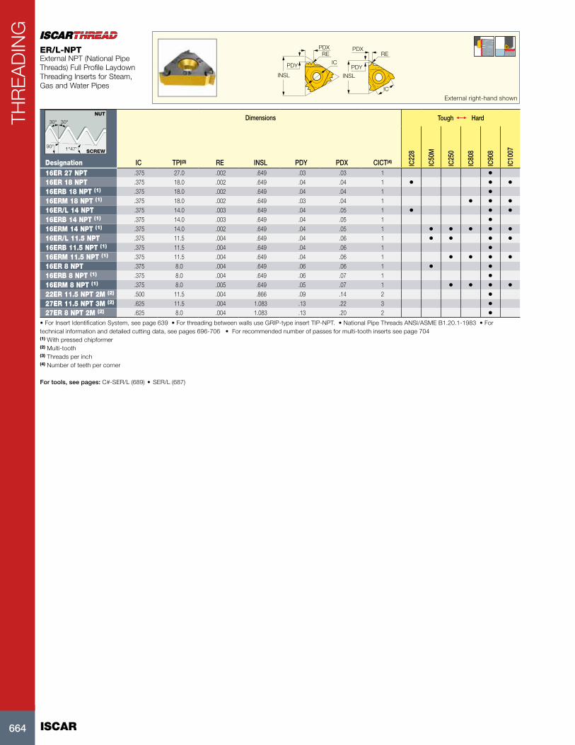
16ER 27 NPT .375 27.0 .002 .649 .03 .03 1 •16ER 18 NPT .375 18.0 .002 .649 .04 .04 1 • • •16ERB 18 NPT (1) .375 18.0 .002 .649 .04 .04 1 •16ERM 18 NPT (1) .375 18.0 .002 .649 .03 .04 1 • • •16ER/L 14 NPT .375 14.0 .003 .649 .04 .05 1 • • •16ERB 14 NPT (1) .375 14.0 .003 .649 .04 .05 1 •16ERM 14 NPT (1) .375 14.0 .002 .649 .04 .05 1 • • • • •16ER/L 11.5 NPT .375 11.5 .004 .649 .04 .06 1 • • • •16ERB 11.5 NPT (1) .375 11.5 .004 .649 .04 .06 1 •16ERM 11.5 NPT (1) .375 11.5 .004 .649 .04 .06 1 • • • •16ER 8 NPT .375 8.0 .004 .649 .06 .06 1 • •16ERB 8 NPT (1) .375 8.0 .004 .649 .06 .07 1 •16ERM 8 NPT (1) .375 8.0 .005 .649 .05 .07 1 • • • •22ER 11.5 NPT 2M (2) .500 11.5 .004 .866 .09 .14 2 •27ER 11.5 NPT 3M (2) .625 11.5 .004 1.083 .13 .22 3 •27ER 8 NPT 2M (2) .625 8.0 .004 1.083 .13 .20 2 •
• For Insert Identification System, see page 639 • For threading between walls use GRIP-type insert TIP-NPT. • National Pipe Threads ANSI/ASME B1.20.1-1983 • For technical information and detailed cutting data, see pages 696-706 • For recommended number of passes for multi-tooth inserts see page 704(1) With pressed chipformer (2) Multi-tooth (3) Threads per inch (4) Number of teeth per corner
For tools, see pages: C#-SER/L (689) • SER/L (687)
ER/L-NPTExternal NPT (National Pipe Threads) Full Profile Laydown Threading Inserts for Steam, Gas and Water Pipes
30°
1°47'90°
30°
NUT
SCREW

665
THR
EA
DIN
G
PDXRE
PDY
lNSL
ICInternal left-hand shown
Dimensions Tough 1 Hard
Designation IC TPI(3) RE INSL PDY PDX CICT(4) IC22
8
IC25
0
IC50
8
IC80
8
IC90
8
IC10
07
06IR 27 NPT .157 27.0 .002 .271 .02 .02 1 •08IR 18 NPT .197 18.0 .002 .324 .02 .03 1 • •11IR/L 18 NPT .250 18.0 .002 .433 .03 .04 1 • •11IRB 18 NPT .250 18.0 .002 .433 .03 .04 1 •11IR/L 14 NPT .250 14.0 .003 .433 .03 .04 1 • • •16IR 27 NPT .375 27.0 .002 .649 .03 .03 1 •16IR 18 NPT .375 18.0 .002 .649 .03 .04 1 •16IRM 14 NPT (1) .375 14.0 .002 .649 .04 .05 1 • • • •16IRB 14 NPT (1) .375 14.0 .003 .649 .04 .05 1 •16IL 14 NPT .375 14.0 .003 .649 .04 .05 1 • • • •16IRM 11.5 NPT (1) .375 11.5 .004 .649 .04 .06 1 • • • •16IRB 11.5 NPT (1) .375 11.5 .004 .649 .04 .06 1 •16IR/L 11.5 NPT .375 11.5 .004 .649 .04 .06 1 • •16IRM 8 NPT (1) .375 8.0 .005 .649 .05 .07 1 • • •16IRB 8 NPT (1) .375 8.0 .004 .649 .05 .07 1 •16IR/L 8 NPT .375 8.0 .004 .649 .05 .07 1 •22IR 11.5 NPT 2M (2) .500 11.5 .004 .866 .09 .14 2 •27IR 11.5 NPT 3M (2) .625 11.5 .004 1.083 .13 .22 3 •27IR 8 NPT 2M (2) .625 8.0 .005 1.083 .12 .20 2 •
• For Insert Identification System, see page 639 • National Pipe Threads ANSI/ASME B1.20.1-1983. • For technical information and detailed cutting data, see pages 696-706 • For recommended number of passes for multi-tooth inserts see page 704(1) With pressed chipformer (2) Multi-tooth (3) Threads per inch (4) Number of teeth per corner
For tools, see pages: MGSIR/L (694) • SIR/L (690)
IR/L-NPTInternal NPT (National Pipe Threads) Full Profile Laydown Threading Inserts for Steam, Gas and Water Pipes
30°
1°47'90°
30°
NUT
SCREW
±.0016.945
.157.142
RE60°
Dimensions
Designation TPI(1) RE IC90
8
PENTA 24-18-NPT 18.0 .003 •PENTA 24-14-NPT 14.0 .004 •
(1) Threads per inch
For tools, see pages: HMSDV PEN (494) • HSTBS-PEN (493) • PCAD RE/LE-JHP (540) • PCADR/L (296) • PCADR/L-JHP (296) • PCHBR/L (297) • PCHPR/L (295) • PCHR/L-24 (292) • PCHR/L-24-JHP (293)
PENTA 24-NPTNPT (National Pipe Threads) Precision Ground Pentagonal External Full Profile Threading Inserts with a Chipformer

ISCAR666
THR
EA
DIN
G
.697 Ref.(a)±.001
60°RE
CW
Dimensions Tough 1 Hard
Designation CW RE RETOL(1) TPI(2) IC08
IC90
8
TIP 2P27-NPT .094 .002 .0012 27.0 • •TIP 2P18-NPT .094 .003 .0012 18.0 • •TIP 2P14-NPT .094 .004 .0012 14.0 •TIP 4P11.5-NPT .157 .004 .0012 11.5 • •TIP 4P8-NPT .157 .005 .0012 8.0 • •
• (a) TIP inserts are .063" longer than GIP in the same pocket • Toolholder seat needs to be modified according to insert profile to ensure clearance(1) Corner radius tolerance (+/-) (2) Threads per inch
For tools, see pages: C#-GHDR/L (251) • CGHN-D (257) • CGHN-DG (258) • CGHN-S (257) • CGPAD (256) • CGPAD-JHP (256) • GHDR/L (short pocket) (251) • GHDR/L-JHP (short pocket) (252) • GHGR/L (253) • GHMPR/L (250) • GHMR/L (250) • GHSR/L (378) • GHSR/L-JHP-SL (379)
TIP-P-NPTNPT (National Pipe Threads) Precision Ground Double-Ended External Full Profile Threading Inserts with a Chipformer
INSL
PDY
PDX
IC
External right-hand shown
Dimensions Tough 1 Hard
Designation IC TPI(1) INSL PDY PDX IC25
0
IC90
8
11ER 14 NPTF .250 14.0 .433 .03 .04 •16ER 27 NPTF .375 27.0 .649 .03 .03 •16ER 18 NPTF .375 18.0 .649 .03 .04 •16ER 14 NPTF .375 14.0 .649 .04 .05 • •16ER 11.5 NPTF .375 11.5 .649 .04 .06 •
• For Insert Identification System, see page 639 • (National Pipe Threads-Dry Seal) ANSI/ASME B1.20.1-1976 full profile • For technical information and detailed cutting data, see pages 696-706(1) Threads per inch
For tools, see pages: C#-SER/L (689) • SER/L (687)
ER-NPTFExternal NPTF (National Pipe Threads) Full Profile Laydown Threading Inserts, for Steam, Gas and Water Pipes
30°
1°47'90°
30°
NUT
SCREW
667
THR
EA
DIN
G
lNSL
PDXPDY RE
IC
Internal left-hand shown
Dimensions Tough 1 Hard
Designation IC TPI(1) RE INSL PDY PDX IC22
8
IC25
0
IC90
8
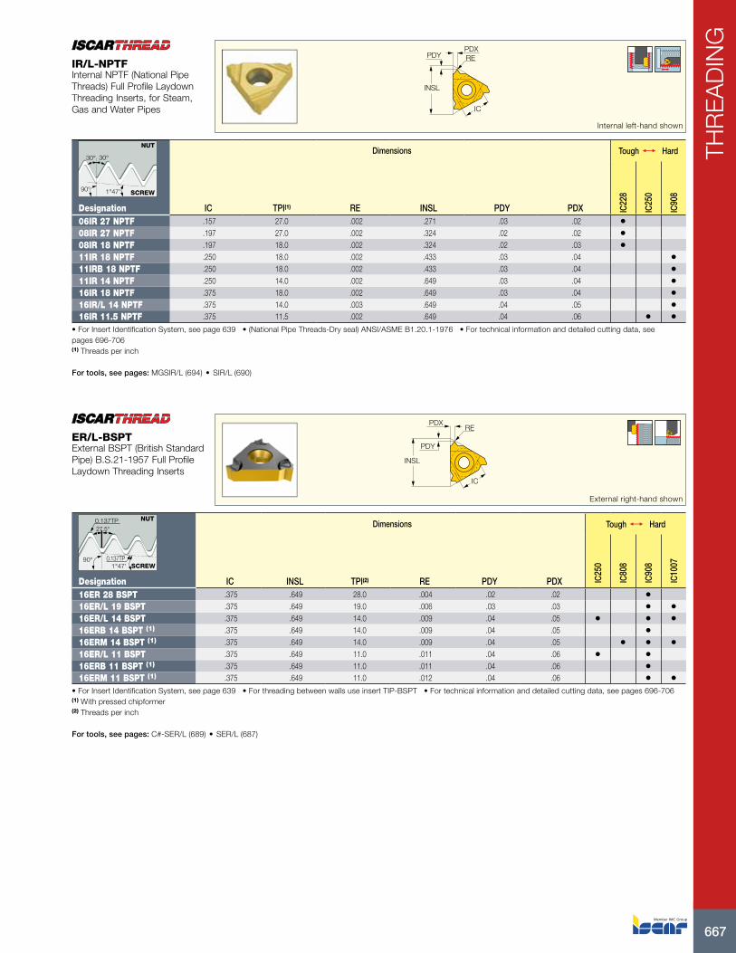
06IR 27 NPTF .157 27.0 .002 .271 .03 .02 •08IR 27 NPTF .197 27.0 .002 .324 .02 .02 •08IR 18 NPTF .197 18.0 .002 .324 .02 .03 •11IR 18 NPTF .250 18.0 .002 .433 .03 .04 •11IRB 18 NPTF .250 18.0 .002 .433 .03 .04 •11IR 14 NPTF .250 14.0 .002 .649 .03 .04 •16IR 18 NPTF .375 18.0 .002 .649 .03 .04 •16IR/L 14 NPTF .375 14.0 .003 .649 .04 .05 •16IR 11.5 NPTF .375 11.5 .002 .649 .04 .06 • •
• For Insert Identification System, see page 639 • (National Pipe Threads-Dry seal) ANSI/ASME B1.20.1-1976 • For technical information and detailed cutting data, see pages 696-706(1) Threads per inch
For tools, see pages: MGSIR/L (694) • SIR/L (690)
IR/L-NPTFInternal NPTF (National Pipe Threads) Full Profile Laydown Threading Inserts, for Steam, Gas and Water Pipes
30°
1°47'90°
30°
NUT
SCREW
PDXRE
PDY
INSL
IC
External right-hand shown
Dimensions Tough 1 Hard
Designation IC INSL TPI(2) RE PDY PDX IC25
0
IC80
8
IC90
8
IC10
07
16ER 28 BSPT .375 .649 28.0 .004 .02 .02 •16ER/L 19 BSPT .375 .649 19.0 .006 .03 .03 • •16ER/L 14 BSPT .375 .649 14.0 .009 .04 .05 • • •16ERB 14 BSPT (1) .375 .649 14.0 .009 .04 .05 •16ERM 14 BSPT (1) .375 .649 14.0 .009 .04 .05 • • •16ER/L 11 BSPT .375 .649 11.0 .011 .04 .06 • •16ERB 11 BSPT (1) .375 .649 11.0 .011 .04 .06 •16ERM 11 BSPT (1) .375 .649 11.0 .012 .04 .06 • •
• For Insert Identification System, see page 639 • For threading between walls use insert TIP-BSPT • For technical information and detailed cutting data, see pages 696-706(1) With pressed chipformer (2) Threads per inch
For tools, see pages: C#-SER/L (689) • SER/L (687)
ER/L-BSPTExternal BSPT (British Standard Pipe) B.S.21-1957 Full Profile Laydown Threading Inserts
0.137TP27.5°
90°1°47'
0.137TP
NUT
SCREW

ISCAR668
THR
EA
DIN
G
PDXPDY
lNSL
IC
RE
Internal left-hand shown
Dimensions Tough 1 Hard
Designation IC INSL TPI(2) RE PDY PDX IC22
8
IC25
0
IC80
8
IC90
8
IC10
07
06IR 28 BSPT .157 .271 28.0 .004 .03 .02 •08IR 28 BSPT .197 .324 28.0 .004 .02 .02 •08IR 19 BSPT .197 .324 19.0 .006 .02 .03 •11IR 19 BSPT .250 .433 19.0 .006 .03 .04 • •11IRB 19 BSPT .250 .433 19.0 .006 .03 .04 •11IR/L 14 BSPT .250 .433 14.0 .009 .04 .04 •16IR 28 BSPT .375 .649 28.0 .004 .02 .02 •16IR 19 BSPT .375 .649 19.0 .006 .03 .04 •16IRB 14 BSPT (1) .375 .649 14.0 .009 .04 .05 •16IRM 14 BSPT (1) .375 .649 14.0 .008 .04 .05 • • •16IL 14 BSPT .375 .649 14.0 .008 .04 .05 •16IRM 11 BSPT (1) .375 .649 11.0 .011 .04 .06 • • •16IRB 11 BSPT (1) .375 .649 11.0 .011 .04 .06 •16IR/L 11 BSPT .375 .649 11.0 .011 .04 .06 • •
• For Insert Identification System, see page 639 • For technical information and detailed cutting data, see pages 696-706(1) With pressed chipformer (2) Threads per inch
For tools, see pages: MGSIR/L (694) • SIR/L (690)
IR/L-BSPTInternal BSPT (British Standard Pipe) B.S.21-1957 Full Profile Laydown Threading Inserts
0.137TP27.5°
90°1°47'
0.137TP
NUT
SCREW
±.0016.945
.177.142
RE60°
Dimensions
Designation TPI(1) RE IC90
8PENTA 24-19-BSPT 19.0 .006 •PENTA 24-14-BSPT 14.0 .009 •
• DMIN(inch)=5.435/TPI(1) Threads per inch
For tools, see pages: HMSDV PEN (494) • HSTBS-PEN (493) • PCAD RE/LE-JHP (540) • PCADR/L (296) • PCADR/L-JHP (296) • PCHBR/L (297) • PCHPR/L (295) • PCHR/L-24 (292) • PCHR/L-24-JHP (293)
PENTA 24-BSPTBSPT (British Standard Pipe) Precision Ground External Pentagonal Full Profile Threading Inserts with a Chipformer
669
THR
EA
DIN
G
.697 Ref.(a)±.001
55°
RE
CW
Dimensions Tough 1 Hard
Designation CW RE RETOL(1) TPI(2)
IC08
IC90
8
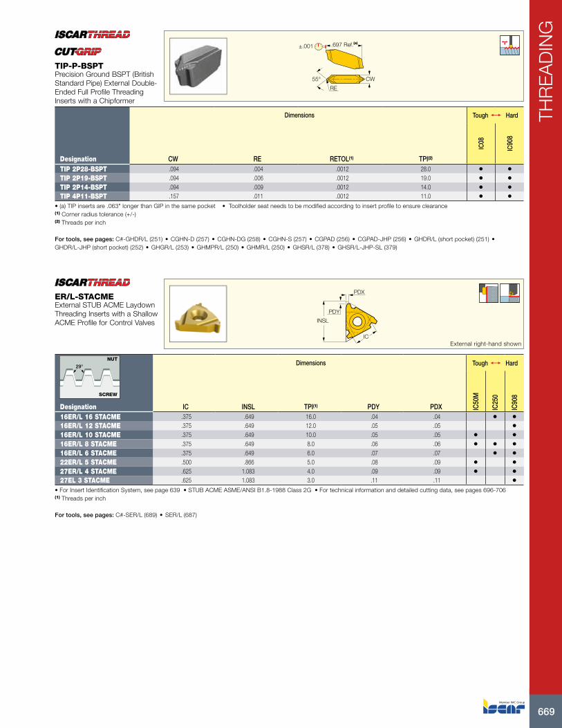
TIP 2P28-BSPT .094 .004 .0012 28.0 • •TIP 2P19-BSPT .094 .006 .0012 19.0 • •TIP 2P14-BSPT .094 .009 .0012 14.0 • •TIP 4P11-BSPT .157 .011 .0012 11.0 • •
• (a) TIP inserts are .063" longer than GIP in the same pocket • Toolholder seat needs to be modified according to insert profile to ensure clearance(1) Corner radius tolerance (+/-) (2) Threads per inch
For tools, see pages: C#-GHDR/L (251) • CGHN-D (257) • CGHN-DG (258) • CGHN-S (257) • CGPAD (256) • CGPAD-JHP (256) • GHDR/L (short pocket) (251) • GHDR/L-JHP (short pocket) (252) • GHGR/L (253) • GHMPR/L (250) • GHMR/L (250) • GHSR/L (378) • GHSR/L-JHP-SL (379)
TIP-P-BSPTPrecision Ground BSPT (British Standard Pipe) External Double-Ended Full Profile Threading Inserts with a Chipformer
INSL
PDY
PDX
ICExternal right-hand shown
Dimensions Tough 1 Hard
Designation IC INSL TPI(1) PDY PDX IC50
M
IC25
0
IC90
8
16ER/L 16 STACME .375 .649 16.0 .04 .04 • •16ER/L 12 STACME .375 .649 12.0 .05 .05 •16ER/L 10 STACME .375 .649 10.0 .05 .05 • •16ER/L 8 STACME .375 .649 8.0 .06 .06 • • •16ER/L 6 STACME .375 .649 6.0 .07 .07 • •22ER/L 5 STACME .500 .866 5.0 .08 .09 • •27ER/L 4 STACME .625 1.083 4.0 .09 .09 • •27EL 3 STACME .625 1.083 3.0 .11 .11 •
• For Insert Identification System, see page 639 • STUB ACME ASME/ANSI B1.8-1988 Class 2G • For technical information and detailed cutting data, see pages 696-706(1) Threads per inch
For tools, see pages: C#-SER/L (689) • SER/L (687)
ER/L-STACMEExternal STUB ACME Laydown Threading Inserts with a Shallow ACME Profile for Control Valves
29°
NUT
SCREW

ISCAR670
THR
EA
DIN
G
PDX PDX
PDY PDY
ICIC
INSLINSL
Internal left-hand shown
Dimensions Tough 1 Hard
Designation IC INSL TPI(1) PDY PDX IC50
M
IC25
0
IC90
8
16IR/L 16 STACME .375 .649 16.0 .04 .04 •16IR 12 STACME .375 .649 12.0 .05 .05 •16IR 10 STACME .375 .649 10.0 .05 .05 • •16IR 8 STACME .375 .649 8.0 .06 .06 • •16IR 6 STACME .375 .649 6.0 .06 .07 • •22IR/L 5 STACME .500 .866 5.0 .08 .09 •22UIR 3 STACME .500 .866 3.0 .13 .43 •27IR/L 4 STACME .625 1.083 4.0 .09 .09 • •27IR/L 3 STACME .625 1.083 3.0 .11 .11 •
• For Insert Identification System, see page 639 • Tolerance: Class 2G. • For technical information and detailed cutting data, see pages 696-706(1) Threads per inch
For tools, see pages: SIR/L (690)
IR/L-STACMEInternal STUB ACME Laydown Threading Inserts with a Shallow ACME Profile for Control Valves
29°
NUT
SCREW
PDX PDX
PDY PDYINSL
INSL
ICIC
External right-hand shown
Dimensions Tough 1 Hard
Designation IC INSL TPI(1) PDY PDX IC50
M
IC25
0
IC90
8
11ER 16 ACME .250 .433 16.0 .04 .04 •16ER 16 ACME .375 .649 16.0 .04 .04 •16ER 12 ACME .375 .649 12.0 .04 .04 •16ER 10 ACME .375 .649 10.0 .05 .05 • •16ER/L 8 ACME .375 .649 8.0 .05 .06 •22ER/L 6 ACME .500 .866 6.0 .07 .08 • •22ER/L 5 ACME .500 .866 5.0 .08 .09 •22ER/L 4 ACME .500 .866 4.0 .08 .09 •22UERL 4 ACME .500 .866 4.0 .09 .43 • •27EL 4 ACME .625 1.083 4.0 .09 .11 • •27UERL 3 ACME .625 1.083 3.0 .11 .54 •
• For Insert Identification System, see page 639 • ACME ASME/ANSI B1.5-1988 Class 3G • For technical information and detailed cutting data, see pages 696-706(1) Threads per inch
For tools, see pages: C#-SER/L (689) • SER/L (687)
ER/L-ACMEExternal ACME Profile Laydown Threading Inserts for Feed Screws
29°
NUT
SCREW
671
THR
EA
DIN
G
INSLINSL
PDY PDY
PDX PDX
ICIC
Internal left-hand shown
Dimensions Tough 1 Hard
Designation IC INSL TPI(1) PDY PDX IC50
M
IC25
0
IC08
IC50
8
IC90
8
16IR/L 16 ACME .375 .649 16.0 .04 .04 • •16IR/L 14 ACME .375 .649 14.0 .04 .05 •16IR/L 12 ACME .375 .649 12.0 .04 .05 • •16IR/L 10 ACME .375 .649 10.0 .05 .05 • •16IR/L 8 ACME .375 .649 8.0 .06 .06 • •22IR/L 6 ACME .500 .866 6.0 .07 .08 • • •22IR/L 5 ACME .500 .866 5.0 .08 .08 • • •22IR 4 ACME .500 .866 4.0 .08 .08 •22UIRL 4 ACME .500 .866 4.0 .09 .43 •27IR/L 4 ACME .625 1.083 4.0 .09 .10 • •27UIRL 3 ACME .625 1.083 3.0 .11 .54 •
• For Insert Identification System, see page 639 • ACME ASME/ANSI B1.5-1988 Class 3G • For technical information and detailed cutting data, see pages 696-706(1) Threads per inch
For tools, see pages: SIR/L (690)
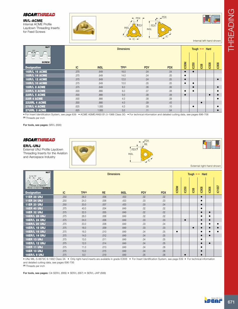
IR/L-ACMEInternal ACME Profile Laydown Threading Inserts for Feed Screws
29°
NUT
SCREW
lNSL
PDY
PDXRE
IC
External right-hand shown
Dimensions Tough 1 Hard
Designation IC TPI(1) RE INSL PDY PDX IC50
M
IC25
0
IC08
IC90
8
IC80
6
IC10
07
11ER 28 UNJ .250 28.0 .006 .433 .02 .02 •11ER 24 UNJ .250 24.0 .006 .433 .03 .03 •11ER 20 UNJ .250 20.0 .007 .433 .03 .04 •16ER 40 UNJ .375 40.0 .004 .649 .02 .02 •16ER 32 UNJ .375 32.0 .005 .649 .02 .02 • •16ER/L 28 UNJ .375 28.0 .006 .649 .02 .02 • •16ER/L 24 UNJ .375 24.0 .006 .649 .03 .03 • • •16ER/L 20 UNJ .375 20.0 .008 .649 .03 .04 • • •16ER/L 18 UNJ .375 18.0 .009 .649 .03 .03 • • • •16ER/L 16 UNJ .375 16.0 .010 .649 .04 .05 • • • •16ER/L 14 UNJ .375 14.0 .012 .649 .04 .05 • •16ER 13 UNJ .375 13.0 .011 .649 .04 .05 •16ER/L 12 UNJ .375 12.0 .014 .649 .04 .05 • •16ER 11 UNJ .375 11.0 .013 .649 .04 .06 •16ER 10 UNJ .375 10.0 .015 .649 .04 .06 •16ER/L 8 UNJ .375 8.0 .019 .649 .05 .06 • •
• UNJ MIL-S-8879C 9-1992 Class 3A • Only right-hand inserts are available in grade IC806 • For Insert Identification System, see page 639 • For technical information and detailed cutting data, see pages 696-706(1) Threads per inch
For tools, see pages: C#-SER/L (689) • SER/L (687) • SER/L-JHP (688)
ER/L-UNJExternal UNJ Profile Laydown Threading Inserts for the Aviation and Aerospace Industry
REmax 0.18042TPREmin 0.15011TP
5/16 TP60°
SCREW
NUT

ISCAR672
THR
EA
DIN
G
INSL
PDXPDY
IC
RE
Internal left-hand shown
Dimensions Tough 1 Hard
Designation IC TPI(1) RE INSL PDY PDX IC22
8
IC50
M
IC90
8
IC80
6
08IR 20 UNJ .197 20.0 .003 .324 .03 .03 •08IR 18 UNJ .197 18.0 .003 .324 .03 .03 •11IR 32 UNJ .250 32.0 .002 .433 .02 .02 •11IRB 32 UNJ .250 32.0 .002 .433 .02 .02 •11IR 28 UNJ .250 28.0 .002 .433 .02 .02 •11IRB 28 UNJ .250 28.0 .002 .433 .02 .02 •11IR 24 UNJ .250 24.0 .002 .433 .03 .03 •11IRB 24 UNJ .250 24.0 .002 .433 .02 .02 •11IR 20 UNJ .250 20.0 .003 .433 .03 .04 •11IRB 20 UNJ .250 20.0 .003 .433 .03 .04 •11IR 18 UNJ .250 18.0 .003 .433 .03 .04 • •11IRB 18 UNJ .250 18.0 .003 .433 .04 .04 •11IR 16 UNJ .250 16.0 .003 .433 .03 .04 •11IRB 16 UNJ .250 16.0 .003 .433 .03 .04 •11IRB 14 UNJ .250 14.0 .004 .433 .03 .04 •16IR 24 UNJ .375 24.0 .002 .649 .03 .03 •16IR 20 UNJ .375 20.0 .003 .649 .03 .03 •16IR 18 UNJ .375 18.0 .003 .649 .03 .03 •16IR/L 16 UNJ .375 16.0 .003 .649 .04 .05 • •16IR 14 UNJ .375 14.0 .004 .649 .04 .04 •16IR/L 12 UNJ .375 12.0 .005 .649 .04 .04 • •16IR/L 8 UNJ .375 8.0 .007 .649 .05 .06 •
• For Insert Identification System, see page 639 • For technical information and detailed cutting data, see pages 696-706(1) Threads per inch
For tools, see pages: SIR/L (690)
IR/L-UNJInternal UNJ Profile Laydown Threading Inserts for the Aviation and Aerospace Industry
REmax 0.18042TPREmin 0.15011TP
5/16 TP60°
SCREW
NUT
INSL
PDXPDY RE
IC
Internal left-hand shown
Dimensions
Designation IC TP(1) INSL RE PDY PDX IC90
8
11IR 1.00 MJ .250 1.000 .433 .002 .02 .02 •11IRB 1.00 MJ .250 1.000 .433 .002 .02 .02 •11IR 1.25 MJ .250 1.250 .433 .003 .03 .04 •11IR 1.50 MJ .250 1.500 .433 .003 .03 .04 •11IRB 1.50 MJ .250 1.500 .433 .003 .03 .04 •11IR 2.00 MJ .250 2.000 .433 .005 .04 .04 •16IR 1.00 MJ .375 1.000 .649 .002 .03 .03 •16IR 1.25 MJ .375 1.250 .649 .003 .03 .04 •16IR 1.50 MJ .375 1.500 .649 .003 .04 .05 •
• For Insert Identification System, see page 639 • For technical information and detailed cutting data, see pages 696-706(1) Thread pitch
For tools, see pages: SIR/L (690)
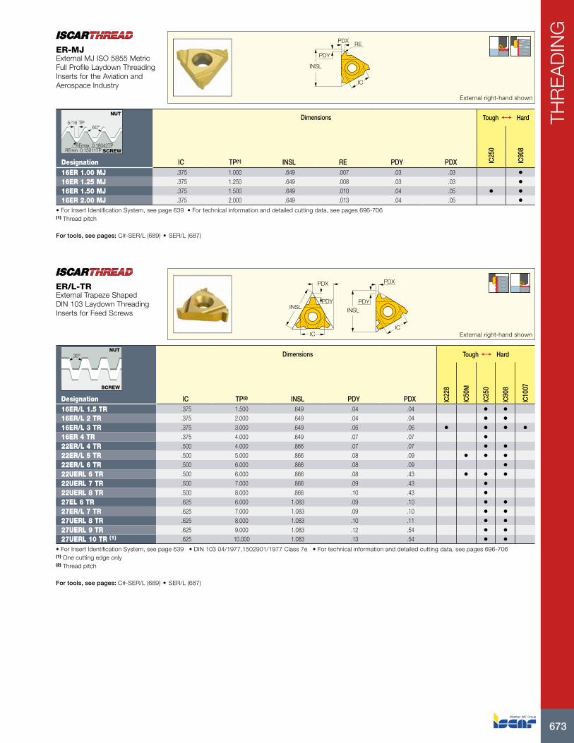
IR-MJInternal MJ ISO 5855 Metric Full Profile Laydown Threading Inserts for the Aviation and Aerospace Industry
REmax 0.18042TPREmin 0.15011TP
5/16 TP60°
SCREW
NUT
673
THR
EA
DIN
G
RE
INSL
PDY
PDX
IC
External right-hand shown
Dimensions Tough 1 Hard
Designation IC TP(1) INSL RE PDY PDX IC25
0
IC90
8
16ER 1.00 MJ .375 1.000 .649 .007 .03 .03 •16ER 1.25 MJ .375 1.250 .649 .008 .03 .03 •16ER 1.50 MJ .375 1.500 .649 .010 .04 .05 • •16ER 2.00 MJ .375 2.000 .649 .013 .04 .05 •
• For Insert Identification System, see page 639 • For technical information and detailed cutting data, see pages 696-706(1) Thread pitch
For tools, see pages: C#-SER/L (689) • SER/L (687)
ER-MJExternal MJ ISO 5855 Metric Full Profile Laydown Threading Inserts for the Aviation and Aerospace Industry
REmax 0.18042TPREmin 0.15011TP
5/16 TP60°
SCREW
NUT
INSL INSL
PDY PDY
PDX PDX
ICIC External right-hand shown
Dimensions Tough 1 Hard
Designation IC TP(2) INSL PDY PDX IC22
8
IC50
M
IC25
0
IC90
8
IC10
07
16ER/L 1.5 TR .375 1.500 .649 .04 .04 • •16ER/L 2 TR .375 2.000 .649 .04 .04 • •16ER/L 3 TR .375 3.000 .649 .06 .06 • • • •16ER 4 TR .375 4.000 .649 .07 .07 •22ER/L 4 TR .500 4.000 .866 .07 .07 • •22ER/L 5 TR .500 5.000 .866 .08 .09 • • •22ER/L 6 TR .500 6.000 .866 .08 .09 •22UERL 6 TR .500 6.000 .866 .08 .43 • • •22UERL 7 TR .500 7.000 .866 .09 .43 •22UERL 8 TR .500 8.000 .866 .10 .43 •27EL 6 TR .625 6.000 1.083 .09 .10 • •27ER/L 7 TR .625 7.000 1.083 .09 .10 • •27UERL 8 TR .625 8.000 1.083 .10 .11 • •27UERL 9 TR .625 9.000 1.083 .12 .54 • •27UERL 10 TR (1) .625 10.000 1.083 .13 .54 • •
• For Insert Identification System, see page 639 • DIN 103 04/1977,1502901/1977 Class 7e • For technical information and detailed cutting data, see pages 696-706(1) One cutting edge only (2) Thread pitch
For tools, see pages: C#-SER/L (689) • SER/L (687)
ER/L-TRExternal Trapeze Shaped DIN 103 Laydown Threading Inserts for Feed Screws
30°NUT
SCREW
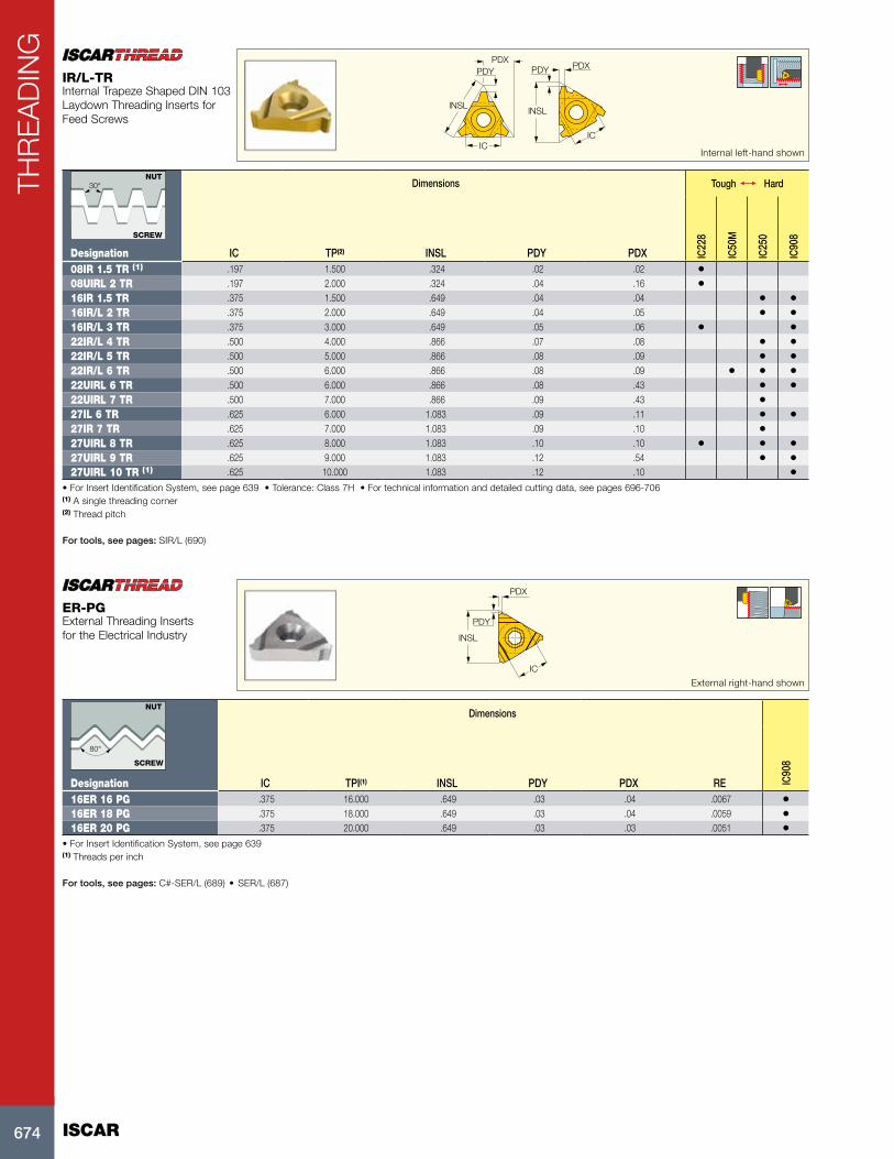
ISCAR674
THR
EA
DIN
GPDX
PDY PDY PDX
ICIC
lNSLlNSL
Internal left-hand shown
Dimensions Tough 1 Hard
Designation IC TP(2) INSL PDY PDX IC22
8
IC50
M
IC25
0
IC90
8
08IR 1.5 TR (1) .197 1.500 .324 .02 .02 •08UIRL 2 TR .197 2.000 .324 .04 .16 •16IR 1.5 TR .375 1.500 .649 .04 .04 • •16IR/L 2 TR .375 2.000 .649 .04 .05 • •16IR/L 3 TR .375 3.000 .649 .05 .06 • •22IR/L 4 TR .500 4.000 .866 .07 .08 • •22IR/L 5 TR .500 5.000 .866 .08 .09 • •22IR/L 6 TR .500 6.000 .866 .08 .09 • • •22UIRL 6 TR .500 6.000 .866 .08 .43 • •22UIRL 7 TR .500 7.000 .866 .09 .43 •27IL 6 TR .625 6.000 1.083 .09 .11 • •27IR 7 TR .625 7.000 1.083 .09 .10 •27UIRL 8 TR .625 8.000 1.083 .10 .10 • • •27UIRL 9 TR .625 9.000 1.083 .12 .54 • •27UIRL 10 TR (1) .625 10.000 1.083 .12 .10 •
• For Insert Identification System, see page 639 • Tolerance: Class 7H • For technical information and detailed cutting data, see pages 696-706(1) A single threading corner (2) Thread pitch
For tools, see pages: SIR/L (690)
IR/L-TRInternal Trapeze Shaped DIN 103 Laydown Threading Inserts for Feed Screws
30°NUT
SCREW
PDY
INSL
PDX
IC
External right-hand shown
Dimensions
Designation IC TPI(1) INSL PDY PDX RE IC90
816ER 16 PG .375 16.000 .649 .03 .04 .0067 •16ER 18 PG .375 18.000 .649 .03 .04 .0059 •16ER 20 PG .375 20.000 .649 .03 .03 .0051 •
• For Insert Identification System, see page 639(1) Threads per inch
For tools, see pages: C#-SER/L (689) • SER/L (687)
ER-PGExternal Threading Inserts for the Electrical Industry
SCREW
80°
NUT

675
THR
EA
DIN
G
PDY PDX
IC
lNSL
Internal left-hand shown
Dimensions
Designation IC TPI(1) RE INSL PDY PDX IC90
8
11IR 18 PG .250 18.000 .006 .433 .03 .04 •16IR 18 PG .375 18.000 .006 .649 .03 .04 •16IR 16 PG .375 16.000 .007 .649 .03 .04 •
• For Insert Identification System, see page 639(1) Threads per inch
For tools, see pages: SIR/L (690)
IR/L-PGInternal Thread Profile Inserts for the Electrical Industry
SCREW
80°
NUT
INSL
PDY
PDX
IC External right-hand shown
Dimensions Tough 1 Hard
Designation IC INSL TP(1) PDY PDX IC25
0
IC90
8
16ER/L 2 SAGE .375 .649 2.000 .04 .06 •22ER 3 SAGE .500 .866 3.000 .06 .09 •22ER/L 4 SAGE .500 .866 4.000 .07 .12 • •22UER 5 SAGE .500 .866 5.000 .05 .46 •22UER/L 6 SAGE .500 .866 6.000 .05 .46 •
• For Insert Identification System, see page 639 • For technical information and detailed cutting data, see pages 696-706(1) Thread pitch
For tools, see pages: C#-SER/L (689) • SER/L (687)
ER/L-SAGEExternal Buttress Thread (DIN 513) for High Force in One Direction Applications
TP
3° 30°
NUT
SCREW
INSL
PDY
PDX
IC
Internal left-hand shown
Dimensions
Designation IC TP(2) INSL PDY PDX IC90
8
16IR/L 2 SAGE .375 2.000 .649 .05 .07 •22IR 3 SAGE .500 3.000 .866 .07 .11 •22IR 4 SAGE .500 4.000 .866 .09 .14 •22UIR 5 SAGE .500 5.000 .866 .07 .46 •22UIR 6 SAGE (1) .500 6.000 .866 .08 .47 •
• For Insert Identification System, see page 639 • For technical information and detailed cutting data, see pages 696-706(1) Requires special anvil (2) Thread pitch
For tools, see pages: SIR/L (690)
IR/L-SAGEInternal Sagengenwinde (DIN 513) Thread Application for High Force in One Direction
TP
3° 30°
NUT
SCREW
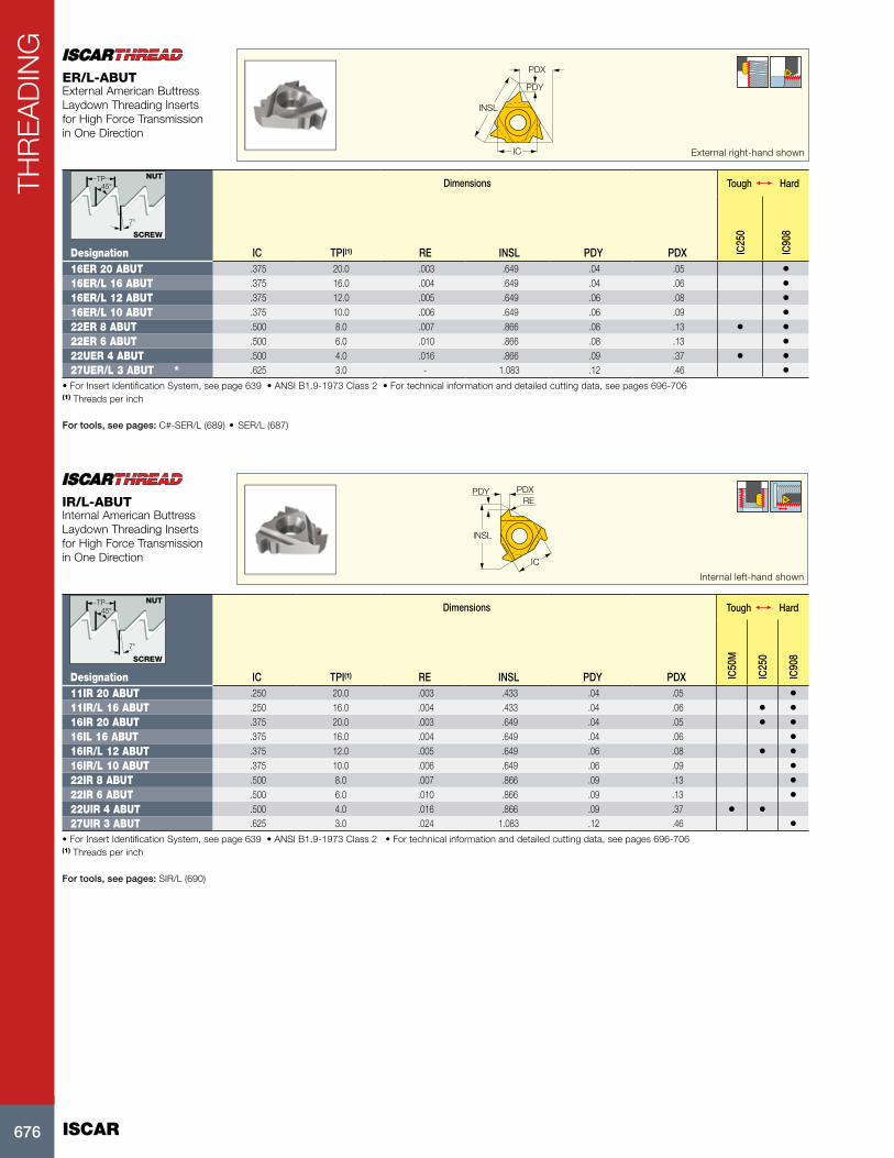
ISCAR676
THR
EA
DIN
GPDX
PDY
INSL
IC External right-hand shown
Dimensions Tough 1 Hard
Designation IC TPI(1) RE INSL PDY PDX IC25
0
IC90
8
16ER 20 ABUT .375 20.0 .003 .649 .04 .05 •16ER/L 16 ABUT .375 16.0 .004 .649 .04 .06 •16ER/L 12 ABUT .375 12.0 .005 .649 .06 .08 •16ER/L 10 ABUT .375 10.0 .006 .649 .06 .09 •22ER 8 ABUT .500 8.0 .007 .866 .08 .13 • •22ER 6 ABUT .500 6.0 .010 .866 .08 .13 •22UER 4 ABUT .500 4.0 .016 .866 .09 .37 • •27UER/L 3 ABUT * .625 3.0 - 1.083 .12 .46 •
• For Insert Identification System, see page 639 • ANSI B1.9-1973 Class 2 • For technical information and detailed cutting data, see pages 696-706(1) Threads per inch
For tools, see pages: C#-SER/L (689) • SER/L (687)
ER/L-ABUTExternal American Buttress Laydown Threading Inserts for High Force Transmission in One Direction
45°TP
7°
NUT
SCREW
PDY PDX
lNSL
IC
RE
Internal left-hand shown
Dimensions Tough 1 Hard
Designation IC TPI(1) RE INSL PDY PDX IC50
M
IC25
0
IC90
8
11IR 20 ABUT .250 20.0 .003 .433 .04 .05 •11IR/L 16 ABUT .250 16.0 .004 .433 .04 .06 • •16IR 20 ABUT .375 20.0 .003 .649 .04 .05 • •16IL 16 ABUT .375 16.0 .004 .649 .04 .06 •16IR/L 12 ABUT .375 12.0 .005 .649 .06 .08 • •16IR/L 10 ABUT .375 10.0 .006 .649 .06 .09 •22IR 8 ABUT .500 8.0 .007 .866 .09 .13 •22IR 6 ABUT .500 6.0 .010 .866 .09 .13 •22UIR 4 ABUT .500 4.0 .016 .866 .09 .37 • •27UIR 3 ABUT .625 3.0 .024 1.083 .12 .46 •
• For Insert Identification System, see page 639 • ANSI B1.9-1973 Class 2 • For technical information and detailed cutting data, see pages 696-706(1) Threads per inch
For tools, see pages: SIR/L (690)
IR/L-ABUTInternal American Buttress Laydown Threading Inserts for High Force Transmission in One Direction
45°TP
7°
NUT
SCREW
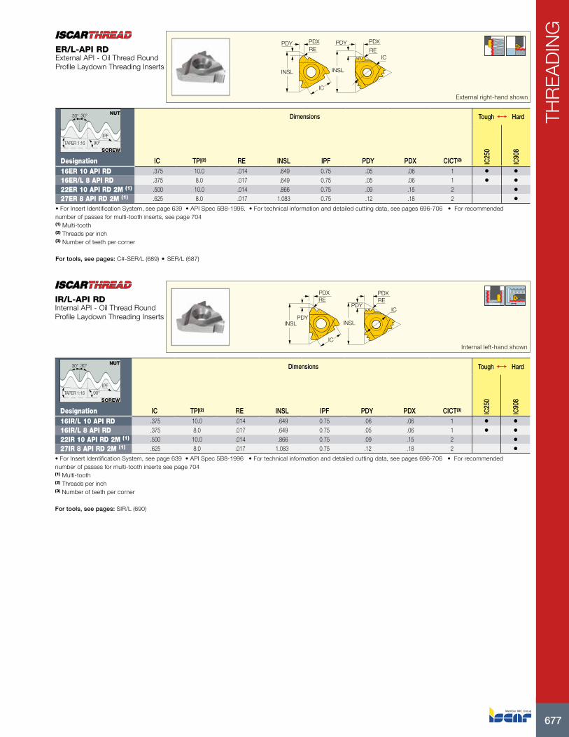
677
THR
EA
DIN
G
PDX PDXPDYPDY
INSL INSL
ICRERE
IC
External right-hand shown
Dimensions Tough 1 Hard
Designation IC TPI(2) RE INSL IPF PDY PDX CICT(3) IC25
0
IC90
8
16ER 10 API RD .375 10.0 .014 .649 0.75 .05 .06 1 • •16ER/L 8 API RD .375 8.0 .017 .649 0.75 .05 .06 1 • •22ER 10 API RD 2M (1) .500 10.0 .014 .866 0.75 .09 .15 2 •27ER 8 API RD 2M (1) .625 8.0 .017 1.083 0.75 .12 .18 2 •
• For Insert Identification System, see page 639 • API Spec 5B8-1996. • For technical information and detailed cutting data, see pages 696-706 • For recommended number of passes for multi-tooth inserts, see page 704(1) Multi-tooth (2) Threads per inch (3) Number of teeth per corner
For tools, see pages: C#-SER/L (689) • SER/L (687)
ER/L-API RDExternal API - Oil Thread Round Profile Laydown Threading Inserts
30° 30°
90°TAPER 1:16
IPF
NUT
SCREW
PDXRE RE
PDX
lNSLPDY
PDY
lNSL
IC
ICInternal left-hand shown
Dimensions Tough 1 Hard
Designation IC TPI(2) RE INSL IPF PDY PDX CICT(3) IC25
0
IC90
8
16IR/L 10 API RD .375 10.0 .014 .649 0.75 .06 .06 1 • •16IR/L 8 API RD .375 8.0 .017 .649 0.75 .05 .06 1 • •22IR 10 API RD 2M (1) .500 10.0 .014 .866 0.75 .09 .15 2 •27IR 8 API RD 2M (1) .625 8.0 .017 1.083 0.75 .12 .18 2 •
• For Insert Identification System, see page 639 • API Spec 5B8-1996 • For technical information and detailed cutting data, see pages 696-706 • For recommended number of passes for multi-tooth inserts see page 704(1) Multi-tooth (2) Threads per inch (3) Number of teeth per corner
For tools, see pages: SIR/L (690)
IR/L-API RDInternal API - Oil Thread Round Profile Laydown Threading Inserts
30° 30°
90°TAPER 1:16
IPF
NUT
SCREW

ISCAR678
THR
EA
DIN
GPDX
PDY
INSL
IC
External right-hand shown
Dimensions Tough 1 Hard
Designation IC RE INSL TPI(4) IPF PDX PDY Size(5) IC25
0
IC90
8
22ER 5 API 403 (1) .500 .0193 .866 5.0 3 .07 .10 2.375"-4.5"REG • •27ER 4 API 382 (2) .625 .0380 1.083 4.0 2 .08 .11 NC23-NC50 • •27ER 4 API 383 (2) .625 .0380 1.083 4.0 3 .08 .11 NC56-NC77 •27ER/L 4 API 502 (3) .625 .0250 1.083 4.0 2 .08 .12 6-5/8" REG • •27ER 4 API 503 (3) .625 .0250 1.083 4.0 3 .08 .12 5-1/2,7-5/8,8-5/8REG •
• For Insert Identification System, see page 639 • For technical information and detailed cutting data, see pages 696-706(1) V-0.040 (2) V-0.038R (3) V-0.050 (4) Threads per inch (5) Connection no. or size
For tools, see pages: C#-SER/L (689) • SER/L (687)
ER/L-APIExternal API - Oil Thread Profile Laydown Threading Inserts
90° IPF
30° 30°TP NUT
SCREW
INSL
PDY
PDX
IC
Internal left-hand shown
Dimensions Tough 1 Hard
Designation IC INSL TPI(1) RE PDY PDX Size(2) IC25
0
IC90
8
22IR 5 API 403 .500 .866 5.0 .0200 .07 .10 2.375"-4.5"REG • •27IR 4 API 382 .625 1.083 4.0 .0380 .08 .11 NC23-NC50 • •27IR 4 API 383 .625 1.083 4.0 .0380 .08 .11 NC56-NC77 •27IR/L 4 API 502 .625 1.083 4.0 .0250 .08 .12 6-5/8" REG •27IR 4 API 503 .625 1.083 4.0 .0250 .08 .12 5-1/2,7-5/8,8-5/8REG •
• For Insert Identification System, see page 639 • 0.050, API Spec 74-1994 • For technical information and detailed cutting data, see pages 696-706(1) Threads per inch (2) Connection no. or size
For tools, see pages: SIR/L (690)
IR/L-APIInternal API - Oil Thread Profile Laydown Threading Inserts
90° IPF
30° 30°TP NUT
SCREW

679
THR
EA
DIN
G
PDX
PDY
INSL
IC
External right-hand shown
Dimensions Tough 1 Hard
Designation IC TPI(1) INSL IPF PDY PDX Size(2) IC25
0
IC90
8
22ER 5 BUT 0.75 .500 5.0 .866 0.75 .09 .09 4-1/2" - 13-3/8" • •22ER 5 BUT-1.00 .500 5.0 .866 1.0 .09 .09 16" - 20" •
• For Insert Identification System, see page 639 • ANSI B1.9.1973 Class 2 • For technical information and detailed cutting data, see pages 696-706(1) Threads per inch (2) Connection no. or size
For tools, see pages: C#-SER/L (689) • SER/L (687)
ER-BUTExternal BUT - Oil Thread Profile Laydown Threading Inserts for Buttress Casing
3° 10°
90° IPF
NUT
SCREW
INSL
PDY
PDX
IC
Internal left-hand shown
Dimensions Tough 1 Hard
Designation IC TPI(1) INSL IPF PDY PDX Size(2) THFT IC25
0
IC90
8
22IR 5 BUT 0.75 .500 5.0 .866 0.75 .09 .09 4-1/2" - 13-3/8" BUT •22IR 5 BUT 1.00 .500 5.0 .866 1.00 .09 .09 16" - 20" BUT •
• For Insert Identification System, see page 639 • API STD.5B.2008 • For technical information and detailed cutting data, see pages 696-706(1) Threads per inch (2) Connection no. or size
For tools, see pages: SIR/L (690)
IR-BUTInternal BUT - Oil Thread Profile Laydown Threading Inserts for Buttress Casing
3° 10°
90° IPF
NUT
SCREW
PDX
PDY
INSL
IC
External right-hand shown
Dimensions Tough 1 Hard
Designation IC TPI(1) INSL IPF PDY PDX Size(2) IC25
0
IC90
8
22ER 6 EL 1.5 .500 6.0 .866 1.5 .07 .07 5" - 7-5/8" • •22ER 5 EL 1.25 .500 5.0 .866 1.25 .09 .09 8-5/8" - 10-3/4" •
• For Insert Identification System, see page 639 • ANSI B1.9.1973 Class 2(1) Threads per inch (2) Connection no. or size
For tools, see pages: C#-SER/L (689) • SER/L (687)
ER-ELExternal EL - Extreme Line Oil Thread Profile Laydown Threading Inserts
6° 6°
90°TAPER- IPF
NUT
SCREW

ISCAR680
THR
EA
DIN
G
INSL
PDY
PDX
IC
Internal left-hand shown
Dimensions
Designation IC TPI(1) INSL IPF PDY PDX Size(2) IC90
8
22IR 6 EL 1.5 .500 6.0 .866 1.5 .08 .08 5" - 7-5/8" •• For Insert Identification System, see page 639 • ANSI B1.9.1973 Class 2(1) Threads per inch (2) Connection no. or size
For tools, see pages: SIR/L (690)
IR-ELInternal EL - Extreme Line Oil Thread Profile Laydown Threading Inserts
6° 6°
90°TAPER- IPF
NUT
SCREW
INSL
PDY PDX
IC
External right-hand shown
Dimensions Tough 1 Hard
Designation IC TPI(2) RE INSL PDY PDX IC22
8
IC25
0
IC50
8
IC90
8
16ER/L 10 RND .375 10.0 .024 .649 .04 .05 • •16ER/L 8 RND .375 8.0 .030 .649 .06 .05 • •16ERM 8 RND (1) .375 8.0 .030 .649 .06 .05 •16ER/L 6 RND .375 6.0 .040 .649 .06 .07 • •16ERM 6 RND (1) .375 6.0 .040 .649 .06 .07 • •22ER 6 RND .500 6.0 .040 .866 .06 .07 • •22ER/L 4 RND .500 4.0 .059 .866 .09 .09 • •27ER 4 RND .625 4.0 .059 1.083 .09 .09 •
• For Insert Identification System, see page 639 • Tolerance: Class 7H • For technical information and detailed cutting data, see pages 696-706(1) With pressed chipformer (2) Threads per inch
For tools, see pages: C#-SER/L (689) • SER/L (687)
ER/L-RNDExternal DIN 405 Round Laydown Threading Inserts for Fire Fighting and Food Industry Pipe Couplings
0.23851TP
30°
0.22105TP0.25597TP
SCREW
NUT

681
THR
EA
DIN
G
INSL
PDY PDX
IC
Internal left-hand shown
Dimensions Tough 1 Hard
Designation IC TPI(2) RE INSL PDY PDX IC25
0
IC90
8
16IR 10 RND .375 10.0 .014 .649 .04 .05 •16IR/L 8 RND .375 8.0 .028 .649 .06 .06 •16IR/L 6 RND .375 6.0 .037 .649 .06 .06 • •16IRM 6 RND (1) .375 6.0 .037 .649 .06 .06 •22IR 6 RND .500 6.0 .037 .866 .06 .07 •22IR 4 RND .500 4.0 .055 .866 .09 .09 •27IR 4 RND .625 4.0 .055 1.083 .09 .09 •
• For Insert Identification System, see page 639 • Tolerance: Class 7H • For technical information and detailed cutting data, see pages 696-706(1) With pressed chipformer (2) Threads per inch
For tools, see pages: SIR/L (690)
IR/L-RNDInternal DIN 405 Round Laydown Threading Inserts for Fire Fighting and Food Industry Pipe Couplings
0.23851TP
30°
0.22105TP0.25597TP
SCREW
NUT

ISCAR682
THR
EA
DIN
G
ISCAR682
USER GUIDE
Grades ISO Coating Layers
IC228 P30-P45 M25-M45 TiN
TiCN
IC250 P15-P35 M20-M40 TiN
TiCN
S.T.IC806
S05-S15 M05-M15
TiAlNAlTiN
S.T. IC808
P15-P30 M20-M30K20-K40 S15-S30H20-H30
TiNTiAlN
IC908P15-P30 M20-M30K20-K40 S15-S30H20-H30 TiAlN
IC1007P10-P20 M05-M15K15-K30 S10-S20 H05-H15
TiNTiAlN
ISCAR Threading Grades Chart
S.T. SUMO TEC PVD COATED
Grades ISO Coating Layers
IC08M15-M30N10-N25S15-S30
UNCOATED

683
THR
EA
DIN
G
683
USER GUIDE
Recommended Applications
TiCN+TiN PVD coated grade on very tough substrate.The grade is recommended for threading of steels and stainless steels at low to medium cutting speeds.
TiCN+TiN PVD coated grade on tough substrate. Used for threading of steels and alloy steels at low to medium cutting speeds.
A hard submicron substrate with AlTiN + TiAlN PVD coating and a special SUMO TEC surface treatment. Suitable for threading of high temperature and titanium alloys at low to medium cutting speeds.
A tough submicron substrate with TiAlN + TiN PVD coating and a special SUMO TEC surface treatment. Recommended for threading of large variety of materials as well as steels, austenitic stainless steels and high temperature alloys at low to medium cutting speeds. Good choice also for nonferrous materials and cast iron.
A tough submicron substrate with TiAlN PVD coating. Recommended for threading of large variety of materials as well as steels, austenitic stainless steels and high temperature alloys at low to medium cutting speeds.Good choice also for nonferrous materials and cast iron.
A hard submicron grain size substrate with TiAlN + TiN PVD coating. Features high plastic deformation resistance.Suitable for threading of steels, stainless steel and hard steels with moderate to high cutting speeds at stable conditions.Good choice also for nonferrous materials and cast iron.
ISCAR Threading Grades Chart
Recommended Applications
An uncoated submicron carbide grade, used for steels, stainless steel and high temperature alloys at low cutting speeds.Good choice also for nonferrous materials.
ISCAR684
THR
EA
DIN
G
THREADING TOOLS
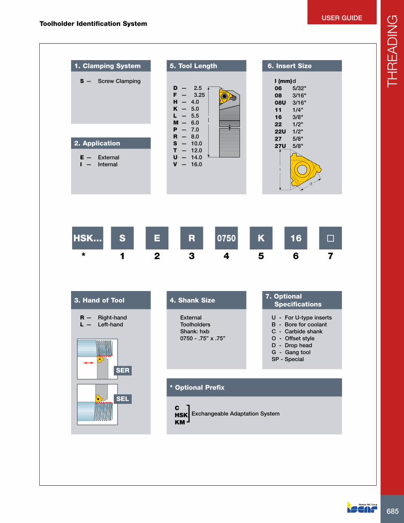
685
THR
EA
DIN
G
685
USER GUIDE
E — ExternalI — Internal
2. Application
1. Clamping System
S
1
HSK...
*
E
2
R
3
0750
4
K
5
16
6
7
7. Optional Specifications
U - For U-type insertsB - Bore for coolantC - Carbide shankO - Offset styleD - Drop headG - Gang toolSP - Special
6. Insert Size
l (mm) d06 5/32"08 3/16"08U 3/16"11 1/4"16 3/8"22 1/2"22U 1/2"27 5/8"27U 5/8"
l
d
Internal ToolholdersShank: diameter d
0025 - Diameter 25mm
External ToolholdersShank: hxb0750 - .75” x .75”
4. Shank Size
R — Right-handL — Left-hand
3. Hand of Tool
D — 2.5F — 3.25H — 4.0K — 5.0L — 5.5M — 6.0P — 7.0R — 8.0S — 10.0T — 12.0U — 14.0V — 16.0
5. Tool Length
l
* Optional Prefix
SER
SEL
S — Screw Clamping
CHSKKM
]Exchangeable Adaptation System
Toolholder Identification System

ISCAR686
THR
EA
DIN
G
ISCAR686
USER GUIDETool Types
Boring Bars
C#-SER/LHSK-SEL
Standard
U-Type
ISCAR GROOVE-TURN TOOLS
PENTACUT Carrying Inserts with 5 Threading Corners For tool information, refer to the Groove-Turn chapter
E-SIR-HEAD Standard
U-Type
GROOVE-TURN Boring Bars
CHAMGROOVE Holder and Carbide Bar
CHAMGROOVE Integral
PICCOCUT Holdersand Carbide Bars

687
THR
EA
DIN
G
HF
WF
10°
H
B
U-TypeLF
LF
BWF
G-Type
Designation H HF B LF WF Insert(2)
SER/L 0310 H11 (1) .310 .310 .310 4.000 .430 11 ER/L..SER/L 0375 H11 (1) .380 .380 .380 4.000 .430 11 ER/L..SER/L 0375 D16 .380 .380 .380 2.500 .630 16 ER/L..SER/L 0500 F16 .500 .500 .500 3.250 .630 16 ER/L..SER/L 0625 H16 .630 .630 .630 4.000 .630 16 ER/L..SER/L 0750 K16 .750 .750 .750 5.000 .750 16 ER/L..SER/L 1000 M16 1.000 1.000 1.000 6.000 1.000 16 ER/L..SER/L 1250 P16 1.250 1.250 1.250 7.000 1.250 16 ER/L..SER/L 1000 M22 1.000 1.000 1.000 6.000 1.000 22 ER/L..SER/L 1500 R22 1.500 1.500 1.500 8.000 1.500 22 ER/L..SER/L 1000 M22U 1.000 1.000 1.000 6.000 1.000 22 UEIRL..SER/L 1250 P22U 1.250 1.250 1.250 7.000 1.250 22 UEIRL..SER 1250 P22U 1.250 1.250 1.250 7.000 1.250 22 UEIRL..SER 1500 R22U 1.500 1.500 1.500 8.000 1.500 22 UEIRL..SER/L 1000 M27 1.000 1.000 1.000 6.000 1.000 27 ER/L..SER/L 1250 P27 1.250 1.250 1.250 7.000 1.250 27 ER/L..SER/L 1500 R27 1.500 1.500 1.500 8.000 1.500 27 ER/L..SER 1000 M27U 1.000 1.000 1.000 6.000 1.000 27 UEIRL..SER/L 1250 P27U 1.250 1.250 1.250 7.000 1.250 27 UEIRL..SER 1500 R27U 1.500 1.500 1.500 8.000 1.500 27 UEIRL..
• All tools are made for 1.5 helix angle • For multi-tooth inserts use anvils AE16M / AI16M; AE22M / AI22M; AE27M / AI27M • For GTGA inserts, use anvil AE 16-0(1) Toolholder without anvil (2) Right-hand inserts (ER) for right-hand tools (SER)
Spare Parts
DesignationSER/L 0310 H11 SR M2.6-L6.7-S11 T-8/5SER/L 0375 H11 SR M2.6-L6.7-S11 T-8/5SEL 0375 D16 AI16 SR 5-40-L6.8-A16 SR 5-40-L12.2-S16 T-10/5SER 0375 D16 AE16 SR 5-40-L6.8-A16 SR 5-40-L12.2-S16 T-10/5SEL 0500 F16 AI16 SR 5-40-L6.8-A16 SR 5-40-L12.2-S16 T-10/5SER 0500 F16 AE16 SR 5-40-L6.8-A16 SR 5-40-L12.2-S16 T-10/5SEL 0625 H16 AI16 SR 5-40-L6.8-A16 SR 5-40-L12.2-S16 T-10/5SER 0625 H16 AE16 SR 5-40-L6.8-A16 SR 5-40-L12.2-S16 T-10/5SEL 0750 K16 AI16 SR 5-40-L6.8-A16 SR 5-40-L12.2-S16 T-10/5SER 0750 K16 AE16 SR 5-40-L6.8-A16 SR 5-40-L12.2-S16 T-10/5SEL 1000 M16 AI16 SR 5-40-L6.8-A16 SR 5-40-L12.2-S16 T-10/5SER 1000 M16 AE16 SR 5-40-L6.8-A16 SR 5-40-L12.2-S16 T-10/5SEL 1250 P16 AI16 SR 5-40-L6.8-A16 SR 5-40-L12.2-S16 T-10/5SER 1250 P16 AE16 SR 5-40-L6.8-A16 SR 5-40-L12.2-S16 T-10/5SEL 1000 M22 AI22 SR 8-32-L5.8-A22 SR 8-32-L15-S22 T-20/5SER 1000 M22 AE22 SR 8-32-L5.8-A22 SR 8-32-L15-S22 T-20/5SER 1250 P22 AE22 SR 8-32-L5.8-A22 SR 8-32-L15-S22 T-20/5SEL 1500 R22 AI22SER/L 1500 R22 SR 8-32-L5.8-A22 SR 8-32-L15-S22 T-20/5SER 1500 R22 AE22SEL 1000 M22U AI22U SR 8-32-L5.8-A22 SR 8-32-L15-S22 T-20/5SER 1000 M22U AE22U SR 8-32-L5.8-A22 SR 8-32-L15-S22 T-20/5SEL 1250 P22U AI22U SR 8-32-L5.8-A22 SR 8-32-L15-S22 T-20/5SER 1250 P22U AE22U SR 8-32-L5.8-A22 SR 8-32-L15-S22 T-20/5SER 1500 R22U AE22U SR 8-32-L5.8-A22 SR 8-32-L15-S22 T-20/5SEL 1000 M27 AI27 SR M5-L5.8-A27 SR M5-L22-S40 T-25/3SER 1000 M27 AE27 SR M5-L5.8-A27 SR M5-L22-S40 T-25/3SEL 1250 P27 AI27 SR M5-L5.8-A27 SR M5-L22-S40 T-25/3SER 1250 P27 AE27 SR M5-L5.8-A27 SR M5-L22-S40 T-25/3SEL 1500 R27 AI27SER/L 1500 R27 SR M5-L5.8-A27 SR M5-L22-S40 T-25/3SER 1500 R27 AE27SER 1000 M27U AE27U SR M5-L5.8-A27 SR M5-L22-S40 T-25/3SEL 1250 P27U AI27U SR M5-L5.8-A27 SR M5-L22-S40SER 1250 P27U AE27U SR M5-L5.8-A27 SR M5-L22-S40 T-25/3SER 1500 R27U AE27U SR M5-L5.8-A27 SR M5-L22-S40 T-25/3
SER/LExternal Threading Toolholders

ISCAR688
THR
EA
DIN
G
H
LH
B
LF
WF
HF
4350PSI
Designation H B HF LF LH WF InsertSER 0750 K16-JHP .750 .750 .750 5.000 1.453 .750 16 ER/L..SER/L 1000 M16-JHP 1.000 1.000 1.000 6.000 1.453 1.000 16 ER/L..
• All tools are made for 1.5 helix angle • For multi-tooth inserts use anvils AE16M / AI16M; AE22M / AI22M; AE27M / AI27M • For GTGA inserts, use anvil AE 16-0For inserts, see pages: ER-MJ (673) • ER-NPTF (666) • ER-PG (674) • ER/L-55° (640) • ER/L-60° (645) • ER/L-ABUT (676) • ER/L-ACME (670) • ER/L-API RD (677) • ER/L-BSPT (667) • ER/L-ISO (652) • ER/L-NPT (664) • ER/L-RND (680) • ER/L-SAGE (675) • ER/L-STACME (669) • ER/L-TR (673) • ER/L-UN (657) • ER/L-UNJ (671) • ER/L-W (661) • GTGA (307) • GTMA (308)
Spare Parts
DesignationSER 0750 K16-JHP SR 5-40-L12.2-S16 AE16 T-8/5 SR 5-40-L6.8-A16 T-10/5 CU-V-JHPSEL 1000 M16-JHP SR 5-40-L12.2-S16 AI16 T-8/5 SR 5-40-L6.8-A16 T-10/5 CU-V-JHPSER 1000 M16-JHP SR 5-40-L12.2-S16 AE16 T-8/5 SR 5-40-L6.8-A16 T-10/5 CU-V-JHP
SER/L-JHPExternal Threading Tools with Coolant Channels

689
THR
EA
DIN
G
DCONMS
WF
LF Right-hand shown
Designation DCONMS WF LF Insert(1)
C4 SER/L-27050-16 40 1.063 1.968 16ERC5 SER/L-35060-16 50 1.378 2.362 16ELC6 SER/L-45065-16 63 1.772 2.559 16ERC4 SER/L-27050-22 40 1.063 1.968 22ERC5 SER/L-35060-22 50 1.378 2.362 22ERC6 SER/L-45065-22 63 1.772 2.559 22ERC8 SER/L-55080-22 80 2.165 3.150 22ER
(1) Right-hand inserts for right-hand tools and vice versa
For inserts, see pages: ER-BUT (679) • ER-EL (679) • ER-MJ (673) • ER-NPTF (666) • ER-PG (674) • ER/L-55° (640) • ER/L-60° (645) • ER/L-ABUT (676) • ER/L-ACME (670) • ER/L-API (678) • ER/L-API RD (677) • ER/L-BSPT (667) • ER/L-ISO (652) • ER/L-NPT (664) • ER/L-RND (680) • ER/L-SAGE (675) • ER/L-STACME (669) • ER/L-TR (673) • ER/L-UN (657) • ER/L-UNJ (671) • ER/L-W (661) • GTGA (307) • GTMA (308)For holders, see pages: HSK-C# (711)
Spare Parts
DesignationC4 SEL-27050-16 AI16 SR 5-40-L6.8-A16 SR 5-40-L12.2-S16 T-10/5C4 SER-27050-16 AE16 SR 5-40-L6.8-A16 SR 5-40-L12.2-S16 T-10/5 EZ 83C5 SEL-35060-16 AI16 SR 5-40-L6.8-A16 SR 5-40-L12.2-S16 T-10/5 EZ 104C5 SER-35060-16 AE16 SR 5-40-L6.8-A16 SR 5-40-L12.2-S16 T-10/5 EZ 104C6 SEL-45065-16 AI16 SR 5-40-L6.8-A16 SR 5-40-L12.2-S16 T-10/5C6 SER-45065-16 AE16 SR 5-40-L6.8-A16 SR 5-40-L12.2-S16 T-10/5C4 SEL-27050-22 AI22 SR 8-32-L5.8-A22 SR 8-32-L15-S22 T-20/5C4 SER-27050-22 AE22 SR 8-32-L5.8-A22 SR 8-32-L15-S22 T-20/5C5 SEL-35060-22 AI22 SR 8-32-L5.8-A22 SR 8-32-L15-S22 T-20/5C5 SER-35060-22 AE22 SR 8-32-L5.8-A22 SR 8-32-L15-S22 T-20/5C6 SEL-45065-22 AI22 SR 8-32-L5.8-A22 SR 8-32-L15-S22 T-20/5C6 SER-45065-22 AE22 SR 8-32-L5.8-A22 SR 8-32-L15-S22 T-20/5C8 SEL-55080-22 AI22 SR 8-32-L5.8-A22 SR 8-32-L15-S22 T-20/5C8 SER-55080-22 AE22 SR 8-32-L5.8-A22 SR 8-32-L15-S22 T-20/5
C#-SER/LExternal Threading Tools with CAMFIX Exchangeable Shanks

ISCAR690
THR
EA
DIN
G
DMIN
LFLDRED
DCONMS
U-Type
Coolant Holes
WF
BDRED
Right-hand shown
SIR/LInternal Threading Bars
Designation DCONMS BDRED LF LH DMIN WF CSP(4) Shank m.(5) Insert(6)
SIR 0205 H06CB (1) .250 .200 4.000 1.000 .240 .170 1 C 06 IR..SIR/L 0205 H06-W (2) .500 .200 4.000 .500 .250 .170 0 S 06 IR/IL..SIR/L 0265 K08 (2) .625 .260 5.000 .710 .315 .210 0 S 08 IR/IL..SIR 0265 K08CB (1) .315 .260 5.000 1.200 .315 .210 1 C 08 IR..SIR/L 0310 K08U (2) .625 .290 5.000 .710 .315 .210 0 S 08 UIRL..SIR 0310 K08UCB (1) .315 .290 5.000 1.400 .355 .250 1 C 08 UIRL..SIR/L 0375 H11 (2) .380 .380 4.000 - .470 .290 0 S 11 IR/IL..SIR/L 0375 K11 (2) .620 .380 5.000 1.000 .470 .260 0 S 11 IR/IL..SIR/L 0375 K11B (2) .625 .380 5.000 .980 .470 .280 1 S 11 IR/IL..SIR 0375 M11CB (1) .380 .380 6.000 - .500 .290 1 C 11 IR..SIR/L 0500 L11 (2) .625 .500 5.500 1.250 .630 .320 0 S 11 IR/IL..SIR 0500 P11CB (1) .500 .500 7.000 - .600 .330 1 C 11 IR..SIR/L 0500 M16 (2) .625 .500 6.000 1.250 .640 .390 0 S 16 IR/IL..SIR/L 0500 M16B (2) .625 .500 6.000 1.260 .640 .390 1 S 16 IR/IL..SIR/L 0625 P16 (2) .750 .625 7.000 1.500 .750 .450 0 S 16 IR/IL..SIR/L 0625 P16B (2) .750 .625 7.000 1.570 .750 .450 1 S 16 IR/IL..SIR 0625 R16CB (1) .625 .625 8.000 - .750 .460 1 C 16 IR..SIR/L 0750 P16 .750 .750 7.000 - 1.000 .510 0 S 16 IR/IL..SIR 0750 P16B .750 .750 7.000 - .900 .510 1 S 16 IR..SIR/L 1000 R16 1.000 1.000 8.000 - 1.200 .650 0 S 16 IR/IL..SIR 1000 R16B 1.000 1.000 8.000 - 1.160 .650 1 S 16 IR..SIR/L 1250 S16 1.250 1.250 10.000 - 1.420 .770 0 S 16 IR/IL..SIR/L 1500 T16 1.500 1.500 12.000 - 1.650 .900 0 S 16 IR/IL..SIR/L 0750 P22 .750 .750 7.000 - .950 .510 0 S 22 IR/IL..SIR/L 1000 R22 1.000 1.000 8.000 - 1.200 .710 0 S 22 IR/IL..SIR 1000 R22B 1.000 1.000 8.000 - 1.160 .710 1 S 22 IR..SIR/L 1250 S22 1.250 1.250 10.000 - 1.500 .850 0 S 22 IR/IL..SIR 1500 T22 1.500 1.500 12.000 - 1.750 .980 0 S 22 IR/IL..SIR/L 1250 S22U 1.250 1.250 10.000 - 1.500 1.010 0 S 22 UIRL..SIR 1500 T22U 1.500 1.500 12.000 - 1.850 1.120 0 S 22 UIRL..SIR/L 1250 S27 1.250 1.250 10.000 - 1.560 .880 0 S 27 IR/IL..SIR/L 1500 T27 1.500 1.500 12.000 - 1.800 1.000 0 S 27 IR/IL..SIR/L 2000 U27 2.000 2.000 14.000 - 2.300 1.250 0 S 27 IR/IL..SIR/L 2500 V27 2.500 2.500 12.600 - 2.700 1.500 0 S 27 IR/IL..SIR/L 1250 S27U (3) 1.250 1.250 10.000 - 1.560 .980 0 S 27 UIRL..SIR/L 1500 T27U (3) 1.500 1.500 12.000 - 1.850 1.130 0 S 27 UIRL..SIR/L 2000 U27U (3) 2.000 2.000 14.000 - 2.300 1.370 0 S 27 UIRL..
• B-steel shank with coolant hole, C-carbide shank without coolant hole, CB-carbide shank with coolant hole • All toolholders are made for 1.5 helix angle • For GTGA inserts, use anvil AL 16-0(1) Carbide shank without anvil (2) Toolholder without anvil (3) For ACME, STUB ACME, TRAPEZ (DIN 103) and ROUND (DIN 405) thread profiles check in user guide for anvil information (4) 0 - Without coolant supply, 1 - With coolant supply (5) C-carbide,S-steel (6) Right-hand inserts (IR) for right-hand tools (SIR)
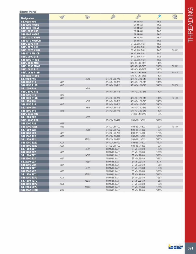
691
THR
EA
DIN
GSpare Parts
DesignationSIL 0205 H06 SR 14-552 T-6/5SIR 0205 H06CB SR 14-552 T-6/5SIR 0205 H06-W SR 14-552 T-6/5SIR/L 0265 K08 SR 14-558 T-6/5SIR 0265 K08CB SR 14-558 T-6/5SIR/L 0310 K08U SR 14-558 T-6/5SIR 0310 K08UCB SR 14-558 T-6/5SIR/L 0375 H11 SR M2.6-L6.7-S11 T-8/5SIR/L 0375 K11 SR M2.6-L6.7-S11 T-8/5SIR/L 0375 K11B SR M2.6-L6.7-S11 T-8/5 PL 062SIR 0375 M11CB SR M2.6-L6.7-S11 T-8/5SIR/L 0500 L11 SR M2.6-L6.7-S11 T-8/5SIR 0500 P11CB SR M2.6-L6.7-S11 T-8/5SIR/L 0500 M16 SR 5-40-L9.7-S16S T-10/5SIR/L 0500 M16B SR 5-40-L9.7-S16S T-10/5 PL 062SIR/L 0625 P16 SR 5-40-L9.7-S16S T-10/5SIR/L 0625 P16B SR 5-40-L9.7-S16S T-10/5 PL 075SIR 0625 R16CB SR 5-40-L9.7-S16S T-10/5SIL 0750 P16 AE16 SR 5-40-L6.8-A16 SR 5-40-L12.2-S16 T-10/5SIR 0750 P16 AI16 SR 5-40-L6.8-A16 SR 5-40-L12.2-S16 T-10/5SIR 0750 P16B AI16 SR 5-40-L6.8-A16 SR 5-40-L12.2-S16 T-10/5 PL 075SIL 1000 R16 AE16SIR/L 1000 R16 SR 5-40-L6.8-A16 SR 5-40-L12.2-S16 T-10/5SIR 1000 R16 AI16SIR 1000 R16B AI16 SR 5-40-L6.8-A16 SR 5-40-L12.2-S16 T-10/5 PL 100SIL 1250 S16 AE16 SR 5-40-L6.8-A16 SR 5-40-L12.2-S16 T-10/5SIR 1250 S16 AI16 SR 5-40-L6.8-A16 SR 5-40-L12.2-S16 T-10/5SIL 1500 T16 AE16 SR 5-40-L6.8-A16 SR 5-40-L12.2-S16 T-10/5SIR 1500 T16 AI16 SR 5-40-L6.8-A16 SR 5-40-L12.2-S16 T-10/5SIR/L 0750 P22 SR 8-32-L12-S22S T-20/5SIL 1000 R22 AE22SIR/L 1000 R22 SR 8-32-L5.8-A22 SR 8-32-L15-S22 T-20/5SIR 1000 R22 AI22SIR 1000 R22B AI22 SR 8-32-L5.8-A22 SR 8-32-L15-S22 T-20/5 PL 100SIL 1250 S22 AE22 SR 8-32-L5.8-A22 SR 8-32-L15-S22 T-20/5SIR 1250 S22 AI22 SR 8-32-L5.8-A22 SR 8-32-L15-S22 T-20/5SIR 1500 T22 AI22 SR 8-32-L5.8-A22 SR 8-32-L15-S22 T-20/5SIL 1250 S22U AE22U SR 8-32-L5.8-A22 SR 8-32-L15-S22 T-20/5SIR 1250 S22U AI22U SR 8-32-L5.8-A22 SR 8-32-L15-S22 T-20/5SIR 1500 T22U AI22U SR 8-32-L5.8-A22 SR 8-32-L15-S22 T-20/5SIL 1250 S27 AE27 SR M5-L5.8-A27 SR M5-L22-S40 T-25/3SIR 1250 S27 AI27 SR M5-L5.8-A27 SR M5-L22-S40 T-25/3SIL 1500 T27 AE27 SR M5-L5.8-A27 SR M5-L22-S40 T-25/3SIR 1500 T27 AI27 SR M5-L5.8-A27 SR M5-L22-S40 T-25/3SIL 2000 U27 AE27 SR M5-L5.8-A27 SR M5-L22-S40 K40SIR 2000 U27 AI27 SR M5-L5.8-A27 SR M5-L22-S40 T-25/3SIL 2500 V27 AE27 SR M5-L5.8-A27 SR M5-L22-S40 T-25/3SIR 2500 V27 AI27 SR M5-L5.8-A27 SR M5-L22-S40 T-25/3SIL 1250 S27U AE27U SR M5-L5.8-A27 SR M5-L22-S40 T-25/3SIR 1250 S27U AI27U SR M5-L5.8-A27 SR M5-L22-S40 T-25/3SIL 1500 T27U AE27U SR M5-L5.8-A27 SR M5-L22-S40 T-25/3SIR 1500 T27U AI27U SR M5-L5.8-A27 SR M5-L22-S40 T-25/3SIL 2000 U27U AE27U SR M5-L5.8-A27 SR M5-L22-S40 T-25/3SIR 2000 U27U AI27U SR M5-L5.8-A27 SR M5-L22-S40 T-25/3

ISCAR692
THR
EA
DIN
G
DCONMS
LU
WF
LF
MinimumBore
Designation DCONMS DMIN WF LU LF InsertC4 SIR/L-12060-16 40 .787 .461 1.457 2.362 16 IR/L..C4 SIR/L-14060-16 40 .984 .531 1.496 2.362 16 IR/L..C4 SIR-15065-22 40 .984 .606 1.654 2.559 22 IR/L..C4 SIR/L-17070-16 40 1.142 .630 1.890 2.756 16 IR/L..C4 SIR/L-19070-22 40 1.142 .705 1.890 2.756 22 IR/L..C4 SIR/L-22090-16 40 1.417 .768 2.717 3.543 16 IR/L..C4 SIR/L-22090-22 40 1.496 .843 2.717 3.543 22 IR/L..C4 SIR/L-27080-16 40 1.732 .925 2.362 3.150 16 IR/L..C4 SIR/L-27080-22 40 1.811 1.000 2.362 3.150 22 IR/L..C5 SIR/L-12060-16 50 .787 .461 1.378 2.362 16 IR/L..C5 SIR/L-14060-16 50 .984 .531 1.417 2.362 16 IR/L..C5 SIR/L-15065-22 50 .984 .606 1.614 2.559 22 IR/L..C5 SIR/L-17070-16 50 1.142 .630 1.850 2.756 16 IR/L..C5 SIR/L-19070-22 50 1.142 .705 1.850 2.756 22 IR/L..C5 SIR/L-22090-16 50 1.417 .768 2.677 3.543 16 IR/L..C5 SIR/L-22090-22 50 1.496 .843 2.677 3.543 22 IR/L..C5 SIR/L-27105-16 50 1.732 .925 3.307 4.134 16 IR/L..C5 SIR/L-27105-22 50 1.811 1.000 3.307 4.134 22 IR/L..C6 SIR/L-14070-16 63 .984 .531 1.654 2.756 16 IR/L..C6 SIR/L-17075-16 63 1.142 .630 1.890 2.953 16 IR/L..C6 SIR/L-19075-22 63 1.142 .705 1.890 2.953 22 IR/L..C6 SIR/L-22090-16 63 1.417 .768 2.520 3.543 16 IR/L..C6 SIR/L-22090-22 63 1.496 .843 2.520 3.543 22 IR/L..C6 SIR/L-27105-16 63 1.732 .925 3.150 4.134 16 IR/L..C6 SIR/L-27105-22 63 1.811 1.000 3.150 4.134 22 IR/L..
For inserts, see pages: IR-BUT (679) • IR-EL (680) • IR-MJ (672) • IR/L-55° (640) • IR/L-60° (646) • IR/L-ABUT (676) • IR/L-ACME (671) • IR/L-API (678) • IR/L-API RD (677) • IR/L-BSPT (668) • IR/L-ISO (653) • IR/L-NPT (665) • IR/L-NPTF (667) • IR/L-PG (675) • IR/L-RND (681) • IR/L-SAGE (675) • IR/L-STACME (670) • IR/L-TR (674) • IR/L-UN (658) • IR/L-UNJ (672) • IR/L-W (662) • GTGA (307) • GTMA (308)
C#-SIR/LInternal Threading Bars with CAMFIX Exchangeable Shanks

693
THR
EA
DIN
GSpare Parts
DesignationC4 SIL-12060-16 AE16 SR 5-40-L6.8-A16 SR 5-40-L12.2-S16 T-10/5C4 SIR-12060-16 AI16 SR 5-40-L6.8-A16 SR 5-40-L12.2-S16 T-10/5C4 SIL-14060-16 AE16 SR 5-40-L6.8-A16 SR 5-40-L12.2-S16 T-10/5C4 SIR-14060-16 AI16 SR 5-40-L6.8-A16 SR 5-40-L12.2-S16 T-10/5C4 SIR-15065-22 AI22 SR 8-32-L5.8-A22 SR 8-32-L15-S22 T-20/5C4 SIL-17070-16 AE16 SR 5-40-L6.8-A16 SR 5-40-L12.2-S16 T-10/5C4 SIL-19070-22 AE22 SR 8-32-L5.8-A22 SR 8-32-L15-S22 T-20/5C4 SIR-17070-16 AI16 SR 5-40-L6.8-A16 SR 5-40-L12.2-S16 T-10/5C4 SIR-19070-22 AI22 SR 8-32-L5.8-A22 SR 8-32-L15-S22 T-20/5C4 SIL-22090-16 AE16 SR 5-40-L6.8-A16 SR 5-40-L12.2-S16 T-10/5C4 SIR-22090-16 AI16 SR 5-40-L6.8-A16 SR 5-40-L12.2-S16 T-10/5C4 SIL-22090-22 AE22 SR 8-32-L5.8-A22 SR 8-32-L15-S22 T-20/5C4 SIR-22090-22 AI22 SR 8-32-L5.8-A22 SR 8-32-L15-S22 T-20/5C4 SIL-27080-16 AE16 SR 5-40-L6.8-A16 SR 5-40-L12.2-S16 T-10/5C4 SIR-27080-16 AI16 SR 5-40-L6.8-A16 SR 5-40-L12.2-S16 T-10/5C4 SIL-27080-22 AE22 SR 8-32-L5.8-A22 SR 8-32-L15-S22 T-20/5C4 SIR-27080-22 AI22 SR 8-32-L5.8-A22 SR 8-32-L15-S22 T-20/5C5 SIL-12060-16 AE16 SR 5-40-L6.8-A16 SR 5-40-L12.2-S16 T-10/5C5 SIR-12060-16 AI16 SR 5-40-L6.8-A16 SR 5-40-L12.2-S16 T-10/5C5 SIL-14060-16 AE16 SR 5-40-L6.8-A16 SR 5-40-L12.2-S16 T-10/5C5 SIL-15065-22 AE22 SR 8-32-L5.8-A22 SR 8-32-L15-S22 T-20/5C5 SIR-14060-16 AI16 SR 5-40-L6.8-A16 SR 5-40-L12.2-S16 T-10/5C5 SIR-15065-22 AI22 SR 8-32-L5.8-A22 SR 8-32-L15-S22 T-20/5C5 SIL-17070-16 AE16 SR 5-40-L6.8-A16 SR 5-40-L12.2-S16 T-10/5C5 SIL-19070-22 AE22 SR 8-32-L5.8-A22 SR 8-32-L15-S22 T-20/5C5 SIR-17070-16 AI16 SR 5-40-L6.8-A16 SR 5-40-L12.2-S16 T-10/5C5 SIR-19070-22 AI22 SR 8-32-L5.8-A22 SR 8-32-L15-S22 T-20/5C5 SIL-22090-16 AE16 SR 5-40-L6.8-A16 SR 5-40-L12.2-S16 T-10/5C5 SIR-22090-16 AI16 SR 5-40-L6.8-A16 SR 5-40-L12.2-S16 T-10/5C5 SIL-22090-22 AE22 SR 8-32-L5.8-A22 SR 8-32-L15-S22 T-20/5C5 SIR-22090-22 AI22 SR 8-32-L5.8-A22 SR 8-32-L15-S22 T-20/5C5 SIL-27105-16 AE16 SR 5-40-L6.8-A16 SR 5-40-L12.2-S16 T-10/5C5 SIR-27105-16 AI16 SR 5-40-L6.8-A16 SR 5-40-L12.2-S16 T-10/5C5 SIL-27105-22 AE22 SR 8-32-L5.8-A22 SR 8-32-L15-S22 T-20/5C5 SIR-27105-22 AI22 SR 8-32-L5.8-A22 SR 8-32-L15-S22 T-20/5C6 SIL-14070-16 AE16 SR 5-40-L6.8-A16 SR 5-40-L12.2-S16 T-10/5C6 SIR-14070-16 AI16 SR 5-40-L6.8-A16 SR 5-40-L12.2-S16 T-10/5C6 SIL-17075-16 AE16 SR 5-40-L6.8-A16 SR 5-40-L12.2-S16 T-10/5C6 SIL-19075-22 AE22 SR 8-32-L5.8-A22 SR 8-32-L15-S22 T-20/5C6 SIR-17075-16 AI16 SR 5-40-L6.8-A16 SR 5-40-L12.2-S16 T-10/5C6 SIR-19075-22 AI22 SR 8-32-L5.8-A22 SR 8-32-L15-S22 T-20/5C6 SIL-22090-16 AE16 SR 5-40-L6.8-A16 SR 5-40-L12.2-S16 T-10/5C6 SIR-22090-16 AI16 SR 5-40-L6.8-A16 SR 5-40-L12.2-S16 T-10/5C6 SIL-22090-22 AE22 SR 8-32-L5.8-A22 SR 8-32-L15-S22 T-20/5C6 SIR-22090-22 AI22 SR 8-32-L5.8-A22 SR 8-32-L15-S22 T-20/5C6 SIL-27105-16 AE16 SR 5-40-L6.8-A16 SR 5-40-L12.2-S16 T-10/5C6 SIR-27105-16 AI16 SR 5-40-L6.8-A16 SR 5-40-L12.2-S16 T-10/5C6 SIL-27105-22 AE22 SR 8-32-L5.8-A22 SR 8-32-L15-S22 T-20/5C6 SIR-27105-22 AI22 SR 8-32-L5.8-A22 SR 8-32-L15-S22 T-20/5
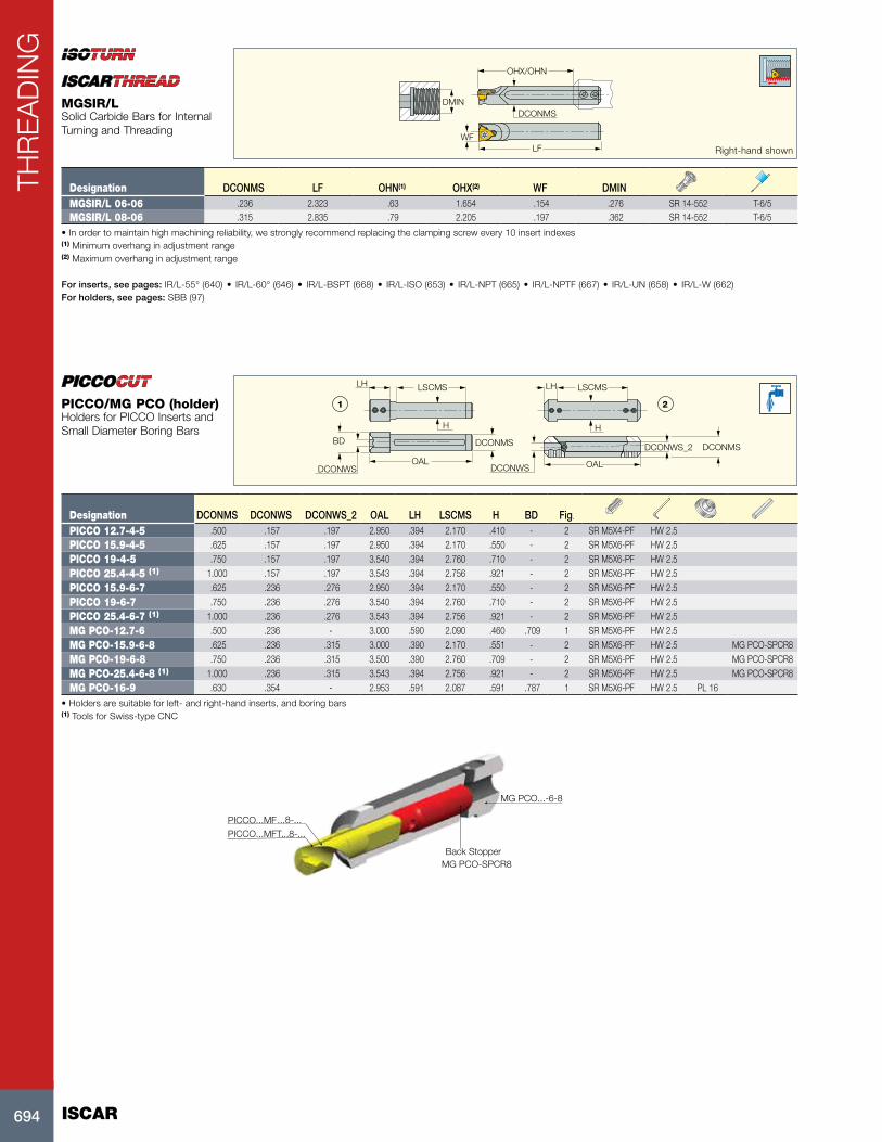
ISCAR694
THR
EA
DIN
G
H H
LH LSCMS LSCMS
OAL OAL
DCONMS DCONMSBD
DCONWS DCONWS
DCONWS_2
LH
1 2
Designation DCONMS DCONWS DCONWS_2 OAL LH LSCMS H BD Fig.
PICCO 12.7-4-5 .500 .157 .197 2.950 .394 2.170 .410 - 2 SR M5X4-PF HW 2.5PICCO 15.9-4-5 .625 .157 .197 2.950 .394 2.170 .550 - 2 SR M5X6-PF HW 2.5PICCO 19-4-5 .750 .157 .197 3.540 .394 2.760 .710 - 2 SR M5X6-PF HW 2.5PICCO 25.4-4-5 (1) 1.000 .157 .197 3.543 .394 2.756 .921 - 2 SR M5X6-PF HW 2.5PICCO 15.9-6-7 .625 .236 .276 2.950 .394 2.170 .550 - 2 SR M5X6-PF HW 2.5PICCO 19-6-7 .750 .236 .276 3.540 .394 2.760 .710 - 2 SR M5X6-PF HW 2.5PICCO 25.4-6-7 (1) 1.000 .236 .276 3.543 .394 2.756 .921 - 2 SR M5X6-PF HW 2.5MG PCO-12.7-6 .500 .236 - 3.000 .590 2.090 .460 .709 1 SR M5X6-PF HW 2.5MG PCO-15.9-6-8 .625 .236 .315 3.000 .390 2.170 .551 - 2 SR M5X6-PF HW 2.5 MG PCO-SPCR8MG PCO-19-6-8 .750 .236 .315 3.500 .390 2.760 .709 - 2 SR M5X6-PF HW 2.5 MG PCO-SPCR8MG PCO-25.4-6-8 (1) 1.000 .236 .315 3.543 .394 2.756 .921 - 2 SR M5X6-PF HW 2.5 MG PCO-SPCR8MG PCO-16-9 .630 .354 - 2.953 .591 2.087 .591 .787 1 SR M5X6-PF HW 2.5 PL 16
• Holders are suitable for left- and right-hand inserts, and boring bars(1) Tools for Swiss-type CNC
MG PCO...-6-8
Back StopperMG PCO-SPCR8
PICCO...MFT...8-...PICCO...MF...8-...
PICCO/MG PCO (holder)Holders for PICCO Inserts and Small Diameter Boring Bars
DMIN
WFLF
OHX/OHN
DCONMS
Right-hand shown
Designation DCONMS LF OHN(1) OHX(2) WF DMINMGSIR/L 06-06 .236 2.323 .63 1.654 .154 .276 SR 14-552 T-6/5MGSIR/L 08-06 .315 2.835 .79 2.205 .197 .362 SR 14-552 T-6/5
• In order to maintain high machining reliability, we strongly recommend replacing the clamping screw every 10 insert indexes(1) Minimum overhang in adjustment range (2) Maximum overhang in adjustment range
For inserts, see pages: IR/L-55° (640) • IR/L-60° (646) • IR/L-BSPT (668) • IR/L-ISO (653) • IR/L-NPT (665) • IR/L-NPTF (667) • IR/L-UN (658) • IR/L-W (662)For holders, see pages: SBB (97)
MGSIR/LSolid Carbide Bars for Internal Turning and Threading

695
THR
EA
DIN
G
DCONMS
OALLSCMS
H
LH
BD DCONWS
Designation DCONMS DCONWS BD OAL LH LSCMS HPICCO ACE 12.7-4 .500 .157 .571 3.346 .906 2.087 .457 PL 16 M6-D5 WRENCH ACE 4-5PICCO ACE 12.7-5 .500 .197 .571 3.346 .906 2.087 .457 PL 16 M6-D5 WRENCH ACE 4-5PICCO ACE 15.9-4 .625 .157 .571 3.346 .846 2.087 .551 PL 16 M6-D5 WRENCH ACE 4-5PICCO ACE 15.9-5 .625 .197 .571 3.346 .846 2.087 .551 PL 16 M6-D5 WRENCH ACE 4-5PICCO ACE 15.9-6 .625 .236 .783 3.346 .906 2.087 .551 PL 16 M6-D5 WRENCH ACE 6-7PICCO ACE 15.9-7 .625 .276 .783 3.346 .906 2.087 .551 PL 16 M6-D5 WRENCH ACE 6-7PICCO ACE 19-4 .750 .157 .571 5.906 .846 4.646 .677 PL 16 M6-D5 WRENCH ACE 4-5PICCO ACE 19-5 .750 .197 .571 5.906 .846 4.646 .677 PL 16 M6-D5 WRENCH ACE 4-5PICCO ACE 19-6 .750 .236 .783 5.906 .906 4.646 .677 PL 16 M6-D5 WRENCH ACE 6-7PICCO ACE 19-7 .750 .276 .783 5.906 .906 4.646 .677 PL 16 M6-D5 WRENCH ACE 6-7PICCO ACE 25.4-4 1.000 .157 .571 5.906 .846 4.646 .905 PL 16 M6-D5 WRENCH ACE 4-5PICCO ACE 25.4-5 1.000 .197 .571 5.906 .846 4.646 .905 PL 16 M6-D5 WRENCH ACE 4-5PICCO ACE 25.4-6 1.000 .236 .783 5.906 .846 4.646 .905 PL 16 M6-D5 WRENCH ACE 6-7PICCO ACE 25.4-7 1.000 .276 .783 5.906 .846 4.646 .905 PL 16 M6-D5 WRENCH ACE 6-7
• Holders are suitable for right- and left-hand PICCO inserts
Cap
Wrench
Locking shim
BodyPins
Locking shim
Cap
Insert
Pin
PICCO ACEHolders for PICCOCUT Inserts

ISCAR696
THR
EA
DIN
G
ISCAR696
USER GUIDE
ISO Material Condition
Tensile Strength
[Kpsi]
Hardness
HB
Material
No.
P
Non-alloy steel and cast steel, free cutting steel
< 0.25 %C Annealed 61 125 1
>= 0.25 %C Annealed 94 190 2
< 0.55 %C Quenched and tempered 123 250 3
>= 0.55 %C Annealed 109 220 4
Quenched and tempered 145 300 5
Low alloy steel and cast steel (less than 5% of alloying elements)
Annealed 87 200 6
Quenched and tempered
135 275 7
145 300 8
174 350 9
High alloyed steel, cast steel, and tool steel
Annealed 99 200 10
Quenched and tempered 160 325 11
Stainless steel and cast steelFerritic/martensitic 99 200 12
Martensitic 119 240 13
M Stainless steel and cast steel Austenitic 87 180 14
K
Cast iron nodular (GG)Ferritic/pearlitic 180 15
Pearlitic 260 16
Grey cast iron (GGG)Ferritic 160 17
Pearlitic 250 18
Malleable cast ironFerritic 130 19
Pearlitic 230 20
N
Aluminum-
wrought alloy
Not cureable 60 21
Cured 100 22
Aluminum-cast,
alloyed
<=12% Si Not cureable 75 23
Cured 90 24
>12% Si High temperature 130 25
Copper alloys
>1% Pb Free cutting 110 26
Brass 90 27
Electrolitic copper 100 28
Non-metallicDuroplastics, fiber plastics 29
Hard rubber 30
SHigh temp. alloys
Fe based Annealed 200 31
Cured 280 32
Ni or Co based
Annealed 250 33
Cured 350 34
Cast 320 35
Titanium Ti alloys58 36
Alpha+beta alloys cured 152 37
HHardened steel
Hardened 55 HRC 38
Hardened 60 HRC 39
Chilled cast iron Cast 400 40
Cast iron Hardened 55 HRC 41
Machining Data for Threading

697
THR
EA
DIN
G
697
USER GUIDE
CoatedIC228 IC908 IC808 IC1007
Cutting Speed (SFM)200 - 330 380 - 620 410 - 670 440 - 750
200 - 310 360 - 590 390 - 640 430 - 720
160 - 300 330 - 570 340 - 610 390 - 690
150 - 280 300 - 540 310 - 570 360 - 660
150 - 280 300 - 540 310 - 570 360 - 660
160 - 310 330 - 590 340 - 640 390 - 710
130 - 250 250 - 460 260 - 490 300 - 560
110 - 230 230 - 440 250 - 480 280 - 520
110 - 230 230 - 440 250 - 480 280 - 520
130 - 210 260 - 390 280 - 430 310 - 480
80 - 160 160 - 330 180 - 340 200 - 390
110 - 230 230 - 430 250 - 460 280 - 510
150 - 200 280 - 360 300 - 390 330 - 430
150 - 250 300 - 460 310 - 490 360 - 560
210 - 280 410 - 520 440 - 560 490 - 620
150 - 210 300 - 390 310 - 430 360 - 480
110 - 230 230 - 430 250 - 460 280 - 510
100 - 200 200 - 380 210 - 410 230 - 460
100 - 110 200 - 230 210 - 250 230 - 280
100 - 250 200 - 480 210 - 510 230 - 570
160 - 640 330 - 1200 340 - 1280 390 - 1440
130 - 380 260 - 720 280 - 770 310 - 870
340 - 710 660 - 1310 710 - 1410 790 - 1570
340 - 490 660 - 920 710 - 980 790 - 1100
340 - 490 660 - 920 710 - 980 790 - 1100
130 - 440 260 - 840 280 - 900 310 - 1000
130 - 440 260 - 840 280 - 900 310 - 1000
130 - 440 260 - 840 280 - 900 310 - 1000
130 - 430 260 - 820 280 - 870 310 - 980
130 - 430 260 - 820 280 - 870 310 - 980
80 - 100 150 - 200 160 - 210 180 - 230
50 - 80 110 - 160 110 - 180 130 - 200
30 - 50 70 - 100 70 - 100 80 - 110
20 - 30 50 - 80 50 - 80 60 - 100
20 - 30 50 - 80 50 - 80 60 - 100
250 - 300 460 - 560 490 - 590 560 - 670
80 - 110 160 - 230 180 - 250 200 - 280
80 - 100 150 - 200 160 - 210 180 - 230
80 - 100 150 - 200 160 - 210 180 - 230
80 - 100 150 - 200 160 - 210 180 - 230
80 - 100 150 - 200 160 - 210 180 - 230
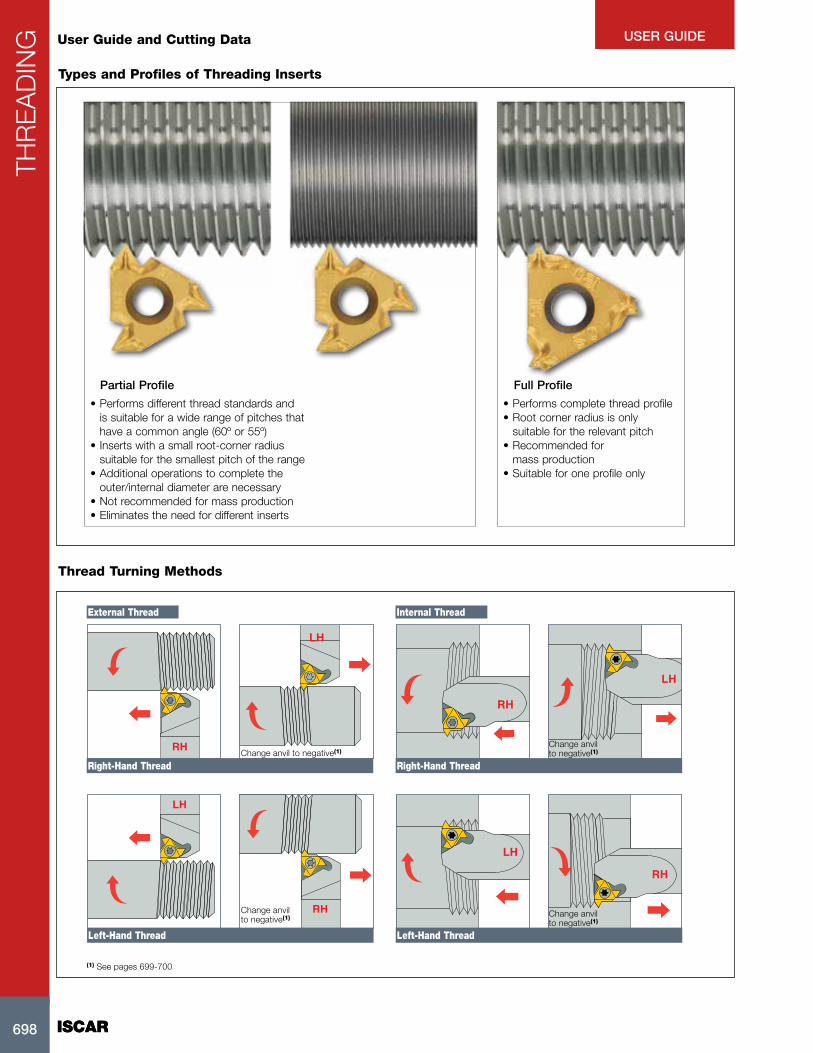
ISCAR698
THR
EA
DIN
G
ISCAR698
USER GUIDE
Types and Profiles of Threading Inserts
User Guide and Cutting Data
Full ProfilePartial Profile
• Performs different thread standards and is suitable for a wide range of pitches that have a common angle (60º or 55º)
• Inserts with a small root-corner radius suitable for the smallest pitch of the range
• Additional operations to complete the outer/internal diameter are necessary
• Not recommended for mass production• Eliminates the need for different inserts
• Performs complete thread profile• Root corner radius is only
suitable for the relevant pitch• Recommended for
mass production• Suitable for one profile only
Thread Turning Methods
External Thread Internal Thread
(1) See pages 699-700
LH
RH
LH
RH
RH
LH
RH
LH
Change anvil to negative(1)
Change anvil to negative(1) Change anvil
to negative(1)
Right-Hand ThreadRight-Hand Thread
Left-Hand ThreadLeft-Hand Thread
Change anvil to negative(1)
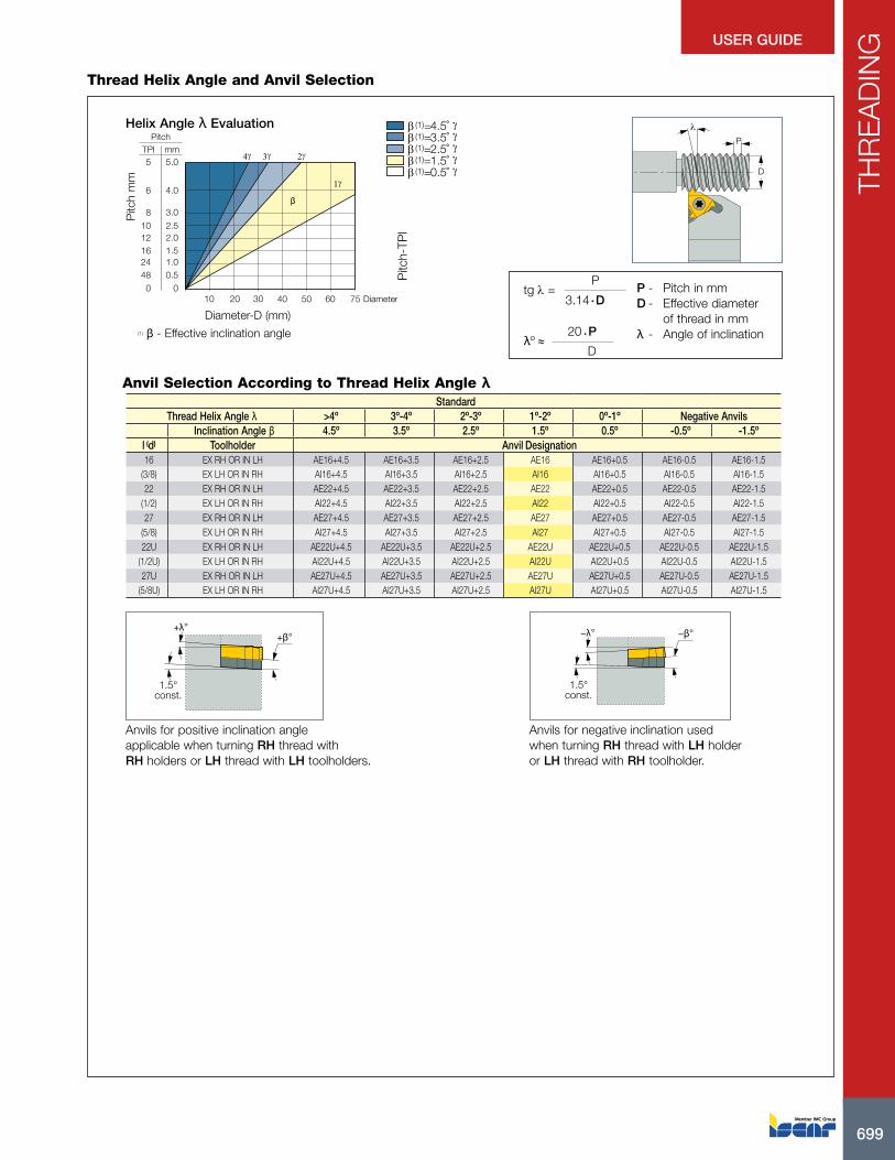
699
THR
EA
DIN
G
699
USER GUIDE
Thread Helix Angle and Anvil Selection
Anvil Selection According to Thread Helix Angle λ
4γ
β
2γ3γ
1γ
40302010 50 60 75
TPIPitch
mm
0.51.01.52.0
3.0
4.0
2.5
0
5.0
48241612
8
6
10
0
5
Diameter
� (1)=4.5˚� (1)=3.5˚� (1)=2.5˚� (1)=1.5˚�
�����(1)=0.5˚
λ
P
D
Diameter-D (mm)
Pitc
h m
m
Pitc
h-TP
I
Helix Angle λ Evaluation
P - Pitch in mmD - Effective diameter of thread in mmλ - Angle of inclination
tg l = P
3.14 · D
λº ≈ 20 · P
D
(1) β - Effective inclination angle
1.5°const.
+λ°+β° −β°−λ°
1.5°const.
Anvils for positive inclination angle applicable when turning RH thread with RH holders or LH thread with LH toolholders.
Anvils for negative inclination used when turning RH thread with LH holder or LH thread with RH toolholder.
StandardThread Helix Angle λ >4º 3º-4º 2º-3º 1º-2º 0º-1º Negative Anvils
Inclination Angle β 4.5º 3.5º 2.5º 1.5º 0.5º -0.5º -1.5ºl (d) Toolholder Anvil Designation16 EX RH OR IN LH AE16+4.5 AE16+3.5 AE16+2.5 AE16 AE16+0.5 AE16-0.5 AE16-1.5
(3/8) EX LH OR IN RH AI16+4.5 AI16+3.5 AI16+2.5 AI16 AI16+0.5 AI16-0.5 AI16-1.522 EX RH OR IN LH AE22+4.5 AE22+3.5 AE22+2.5 AE22 AE22+0.5 AE22-0.5 AE22-1.5
(1/2) EX LH OR IN RH AI22+4.5 AI22+3.5 AI22+2.5 AI22 AI22+0.5 AI22-0.5 AI22-1.527 EX RH OR IN LH AE27+4.5 AE27+3.5 AE27+2.5 AE27 AE27+0.5 AE27-0.5 AE27-1.5
(5/8) EX LH OR IN RH AI27+4.5 AI27+3.5 AI27+2.5 AI27 AI27+0.5 AI27-0.5 AI27-1.522U EX RH OR IN LH AE22U+4.5 AE22U+3.5 AE22U+2.5 AE22U AE22U+0.5 AE22U-0.5 AE22U-1.5
(1/2U) EX LH OR IN RH AI22U+4.5 AI22U+3.5 AI22U+2.5 AI22U AI22U+0.5 AI22U-0.5 AI22U-1.527U EX RH OR IN LH AE27U+4.5 AE27U+3.5 AE27U+2.5 AE27U AE27U+0.5 AE27U-0.5 AE27U-1.5
(5/8U) EX LH OR IN RH AI27U+4.5 AI27U+3.5 AI27U+2.5 AI27U AI27U+0.5 AI27U-0.5 AI27U-1.5
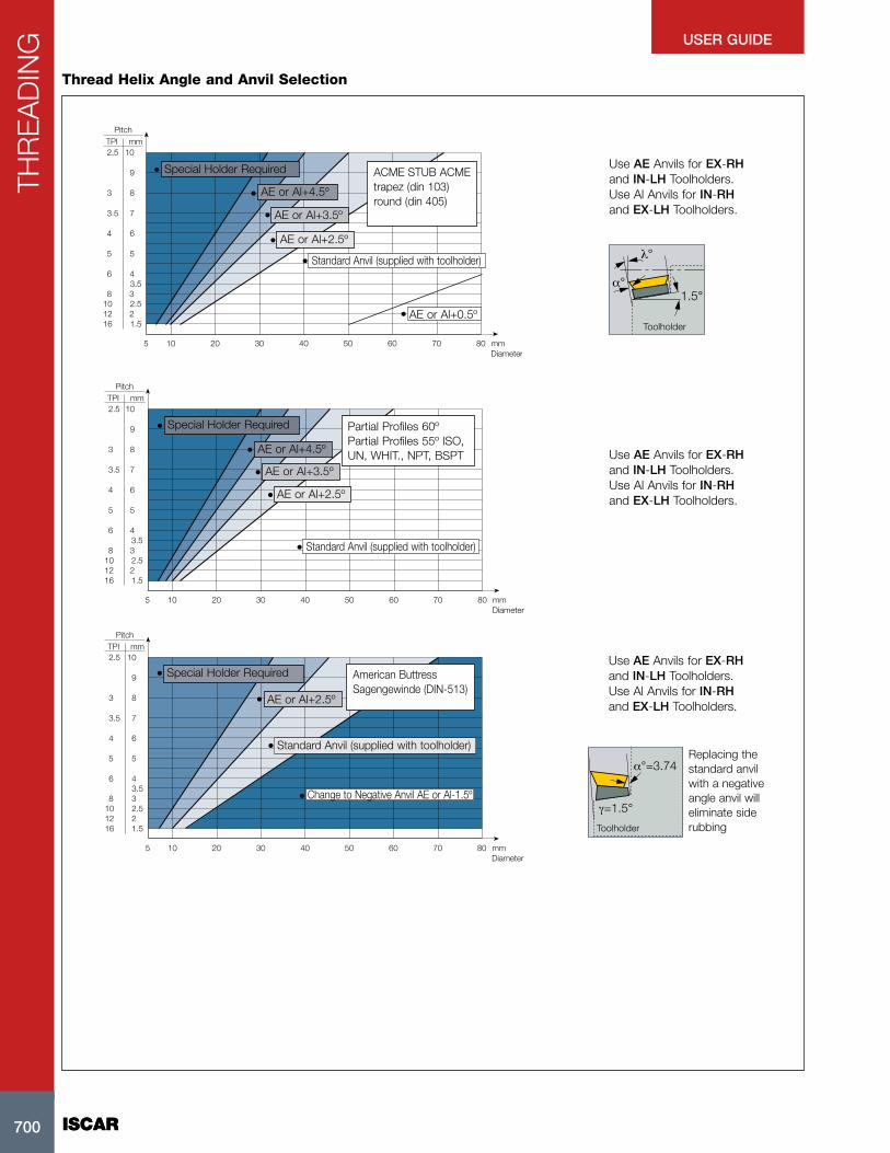
ISCAR700
THR
EA
DIN
G
ISCAR700
USER GUIDE
Thread Helix Angle and Anvil Selection
Use AE Anvils for EX-RH and IN-LH Toolholders. Use Al Anvils for IN-RH and EX-LH Toolholders.
λ°
1.5α°
°
Toolholder
105 20 30 40 50 60 70 80
1.522.53
4
5
6
7
8
9
10
3.5
mm
Diametermm
TPIPitch
1612108
6
5
4
3.5
3
2.5
ACME STUB ACME trapez (din 103) round (din 405)
Special Holder Required
AE or Al+4.5º
AE or Al+3.5º
AE or Al+2.5º
AE or Al+0.5º
Standard Anvil (supplied with toolholder)
Use AE Anvils for EX-RH and IN-LH Toolholders. Use Al Anvils for IN-RH and EX-LH Toolholders.
105 20 30 40 50 60 70 80
1.522.53
4
5
6
7
8
9
10
3.5
mm
Diametermm
TPIPitch
1612108
6
5
4
3.5
3
2.5
Special Holder Required
AE or Al+4.5º
AE or Al+3.5º
AE or Al+2.5º
Partial Profiles 60º Partial Profiles 55º ISO, UN, WHIT., NPT, BSPT
Standard Anvil (supplied with toolholder)
°
α°=3.74
γ=1.5
Use AE Anvils for EX-RH and IN-LH Toolholders. Use Al Anvils for IN-RH and EX-LH Toolholders.
Replacing the standard anvil with a negative angle anvil will eliminate side rubbingToolholder
105 20 30 40 50 60 70 80
1.522.53
4
5
6
7
8
9
10
3.5
mm
Diametermm
TPIPitch
1612108
6
5
4
3.5
3
2.5
Special Holder Required
AE or Al+2.5º
American Buttress Sagengewinde (DIN-513)
Standard Anvil (supplied with toolholder)
Change to Negative Anvil AE or Al-1.5º

701
THR
EA
DIN
G
701
USER GUIDE
Mini-Tool Features
(1)
(2)
(3)
øD M8; 5/16”-UN; 1/16”-NPT
4H÷8H/1B÷3B
A 0.00
(1) Smallest possible thread(2) All tolerances(3) Minimum runout(4) High surface quality
A
Flank Clearance and Effective Inclination AngleInclination angle β of the cutting edges corresponds to a specific thread helix angle l and ensures an equal clearance angle on both sides of the insert.
α - Flank clearance anglel - Helix angleβ - Effective inclination angle is achieved by selecting the suitable anvil
λ
=0
α α
β
LR
λ
β
αL αR
αl=αrIncorrect
αl<αr
Infeed Methods for Threading OperationsFlank Infeed
D1/2D2/2D3/2Dn/2
U/2
H/2
D/2
Flank Equal Equal depth of cut for each pass
D1/2D2/2D3/2
Dn+1/2D/2
U/2
Dn/2
1-3°
Flank DiminishingDiminished depth of cut for each pass Modified Flank Infeed
Radial Infeed
1
23
4
5
Alternating Flanks Infeed
H - Depth of thread profile (on ø)D - Depth of pass (on ø)U - Depth of finishing pass (on ø)
D1
2=
D2
2=
D3
2=
Dn
2
D1
2>
D2
2>
D3
2> >
Dn
2
Dn+1
2

ISCAR702
THR
EA
DIN
G
ISCAR702
USER GUIDE
Full Profile Pitch TPIInsertDesignation
No. of
Passes
Max. Depth for First Pass (D1)
Low Carbon Steel High Carbon Steel Alloy Steel Stainless SteelNonferrous Aluminium
Min. Max. Eq.(2) Dim.(3) Eq.(2) Dim.(3) Eq.(2) Dim.(3) Eq.(2) Dim.(3) Eq.(2) Dim.(3)
ISO
Metric
1.00 16 ER/L 1.00 ISO 5 9 .013 .020 .012 .018 .011 .016 .009 .013 .019 .0281.25 16 ER/L 1.25 ISO 6 11 .017 .025 .015 .022 .013 .020 .011 .016 .023 .0351.50 16 ER/L 1.50 ISO 6 12 .018 .027 .016 .024 .015 .022 .012 .018 .025 .0381.75 16 ER/L 1.75 ISO 8 13 .019 .028 .017 .026 .015 .023 .012 .019 .026 .0402.00 16 ER/L 2.00 ISO 8 14 .020 .030 .018 .027 .016 .024 .013 .019 .028 .0412.50 16 ER/L 2.50 ISO 10 15 .021 .031 .019 .028 .017 .025 .013 .020 .029 .0443.00 16 ER/L 3.00 ISO 12 17 .022 .033 .020 .030 .018 .026 .014 .022 .031 .046
American
UN
24 16 ER/L 24 UN 5 9 .013 .020 .012 .018 .011 .016 .009 .013 .019 .02820 16 ER/L 20 UN 6 10 .017 .025 .015 .022 .013 .020 .011 .016 .023 .03518 16 ER/L 18 UN 6 11 .018 .027 .016 .024 .015 .022 .012 .018 .025 .03816 16 ER/L 16 UN 7 12 .019 .028 .017 .025 .015 .022 .012 .018 .026 .03912 16 ER/L 12 UN 8 14 .020 .030 .018 .027 .016 .024 .013 .019 .028 .041 8 16 ER/L 8 UN 12 17 .022 .033 .020 .030 .018 .026 .014 .022 .031 .046
British
BSW
16 16 ER/L 16 W 7 12 .019 .028 .017 .025 .015 .022 .012 .018 .026 .03914 16 ER/L 14 W 8 13 .020 .030 .018 .027 .016 .024 .013 .019 .028 .04111 16 ER/L 11 W 9 14 .017 .026 .016 .023 .014 .021 .011 .017 .024 .036
NPT18 16 ER/L 18 NPT 10 20 .009 .014 .009 .013 .007 .011 .006 .009 .013 .020
11.5 16 ER/L 11.5 NPT 15 24 .011 .016 .009 .014 .009 .013 .007 .010 .015 .022 8 16 ER/L 8 NPT 17 30 .012 .018 .011 .016 .010 .015 .008 .012 .017 .025
Round 6 16 ER/L 6 Rnd 9 20 .017 .025 .015 .022 .013 .020 .011 .016 .023 .035
Partial
Profile 60º
0.50-1.50 48-16 16 ER/L A60 (1) .009 .013 .008 .012 .007 .010 .006 .008 .012 .0181.75-3.00 14-8 16 ER/L G60 .020 .030 .018 .027 .016 .024 .013 .019 .028 .0410.50-3.00 48-8 16 ER/L AG60 .009 .014 .009 .013 .007 .011 .006 .009 .013 .0203.50-5.00 7-5 22 ER/L N60 .016 .024 .015 .022 .013 .020 .011 .016 .022 .034
Partial
Profile 55º1.75-3.00 14-8 16 ER/L G55 .020 .030 .018 .027 .016 .024 .013 .019 .028 .0410.50-3.00 48-8 16 ER/L AG55 .009 .013 .008 .012 .007 .010 .006 .008 .012 .018
Maximum Depth of First Cut for CNC ControlExternal Threading - M-Type Inserts
(1) Per the number of passes for the relevant pitch(2) Equal depth of cut method(3) Diminished depth of cut for each pass method
Number of Cutting Passes for Regular Type Inserts
TPI Pitch mm0.5
48
1.0
24
1.5
16
2.0
12
2.5
10
3.0
8
4.0
6
6.0
4
Number of Passes 4-6 5-9 5-12 6-14 7-15 8-17 10-20 11-22
For mini-tools (06IR or 08IR) add 1-3 passes. Increase for hard materials.

703
THR
EA
DIN
G
703
USER GUIDE
Maximum Depth of First Cut for CNC ControlInternal Threading - M-Type Inserts
(1) Per the number of passes for the relevant pitch(2) Equal depth of cut method(3) Diminished depth of cut for each pass method
Full Profile Pitch TPIInsertDesignation
No. of
Passes
Max. Depth for First Pass (D1)
Low Carbon Steel High Carbon Steel Alloy Steel Stainless SteelNonferrous Aluminium
Min. Max. Eq.(2) Dim.(3) Eq.(2) Dim.(3) Eq.(2) Dim.(3) Eq.(2) Dim.(3) Eq.(2) Dim.(3)
ISO
Metric
1.00 16 IRM 1.00 ISO 9 16 .006 .008 .005 .007 .004 .006 .004 .005 .008 .0111.25 16 IRM 1.25 ISO 9 16 .007 .011 .007 .010 .006 .009 .005 .007 .011 .0151.50 16 IRM 1.50 ISO 10 20 .008 .012 .007 .011 .006 .009 .005 .008 .011 .0191.75 16 IRM 1.75 ISO 11 18 .008 .013 .007 .011 .007 .010 .006 .008 .011 .0182.00 16 IRM 2.00 ISO 12 21 .009 .013 .008 .012 .007 .010 .006 .008 .012 .0182.50 16 IRM 2.50 ISO 14 21 .009 .013 .008 .012 .007 .011 .006 .009 .013 .0193.00 16 IRM 3.00 ISO 16 22 .009 .014 .009 .013 .007 .011 .006 .009 .013 .020
American
UN
16
16 IRM 16 UN 11 19 .008 .012 .007 .011 .006 .009 .005 .008 .011 .01712 16 IRM 12 UN 12 21 .009 .013 .008 .012 .007 .011 .006 .009 .013 .019 8 16 IRM 8 UN 14 20 .009 .014 .009 .013 .007 .011 .006 .009 .013 .020
British
BSW
16 16 IRM 16 W 9 14 .010 .015 .009 .014 .008 .012 .007 .010 .014 .02214 16 IRM 14 W 10 16 .011 .016 .009 .015 .009 .013 .007 .011 .015 .02211 16 IRM 11 W 12 19 .012 .018 .011 .016 .010 .015 .008 .012 .017 .025
NPT 11.5 16 IRM 11.5 NPT 21 33 .007 .010 .006 .009 .006 .008 .004 .006 .009 .014Round 6 16 IRM 6 RND 12 24 .012 .018 .011 .016 .009 .015 .008 .012 .017 .025
Partial
Profile 60º
0.50-1.25 48-16 06 IRM A60 .009 .013 .008 .012 .007 .010 .006 .008 .012 .0180.50-1.50 48-16 08 IRM A60 (1) .005 .008 .005 .007 .004 .006 .003 .005 .007 .0110.50-1.50 48-16 11 IRM A60 .005 .008 .005 .007 .004 .006 .003 .005 .007 .0110.50-1.50 48-16 16 IRM A60 .005 .008 .005 .007 .004 .006 .003 .005 .007 .0111.75-3.00 14-8 16 IRM G60 .009 .013 .008 .012 .007 .010 .006 .008 .012 .0180.50-3.00 48-8 16 IRM AG60 .006 .008 .005 .007 .004 .007 .004 .006 .008 .0113.50-5.00 7-5 22 IRM N60 .009 .013 .008 .012 .007 .011 .006 .009 .013 .019
Partial
Profile 55º1.75-3.00 14-8 16 IRM G55 .013 .020 .012 .018 .011 .016 .009 .013 .019 .0280.50-3.00 48-8 16 IRM AG55 .006 .008 .005 .007 .004 .006 .004 .005 .008 .011
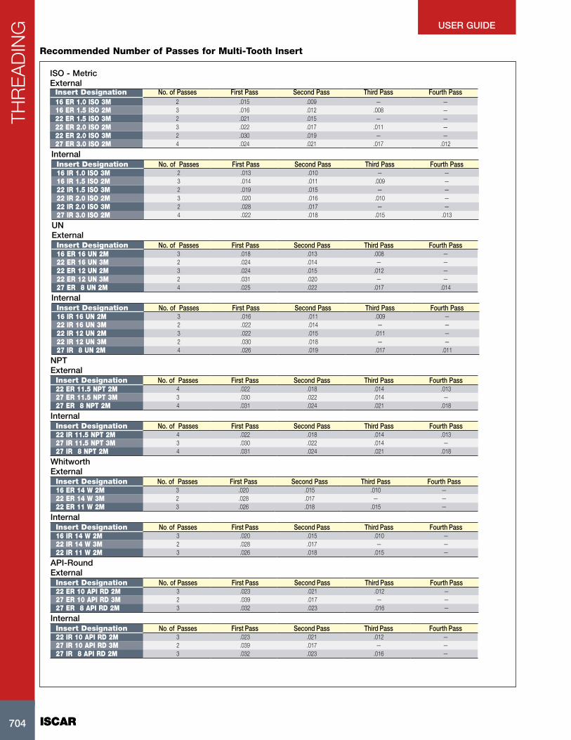
ISCAR704
THR
EA
DIN
G
ISCAR704
USER GUIDE
Recommended Number of Passes for Multi-Tooth Insert
Insert Designation No. of Passes First Pass Second Pass Third Pass Fourth Pass16 ER 1.0 ISO 3M 2 .015 .009 — —16 ER 1.5 ISO 2M 3 .016 .012 .008 —22 ER 1.5 ISO 3M 2 .021 .015 — —22 ER 2.0 ISO 2M 3 .022 .017 .011 —22 ER 2.0 ISO 3M 2 .030 .019 — —27 ER 3.0 ISO 2M 4 .024 .021 .017 .012
ISO - MetricExternal
Insert Designation No. of Passes First Pass Second Pass Third Pass Fourth Pass16 IR 1.0 ISO 3M 2 .013 .010 — —16 IR 1.5 ISO 2M 3 .014 .011 .009 —22 IR 1.5 ISO 3M 2 .019 .015 — —22 IR 2.0 ISO 2M 3 .020 .016 .010 —22 IR 2.0 ISO 3M 2 .028 .017 — —27 IR 3.0 ISO 2M 4 .022 .018 .015 .013
Internal
Insert Designation No. of Passes First Pass Second Pass Third Pass Fourth Pass16 ER 16 UN 2M 3 .018 .013 .008 —22 ER 16 UN 3M 2 .024 .014 — —22 ER 12 UN 2M 3 .024 .015 .012 —22 ER 12 UN 3M 2 .031 .020 — —27 ER 8 UN 2M 4 .025 .022 .017 .014
UNExternal
Insert Designation No. of Passes First Pass Second Pass Third Pass Fourth Pass16 IR 16 UN 2M 3 .016 .011 .009 —22 IR 16 UN 3M 2 .022 .014 — —22 IR 12 UN 2M 3 .022 .015 .011 —22 IR 12 UN 3M 2 .030 .018 — —27 IR 8 UN 2M 4 .026 .019 .017 .011
Internal
Insert Designation No. of Passes First Pass Second Pass Third Pass Fourth Pass22 ER 11.5 NPT 2M 4 .022 .018 .014 .01327 ER 11.5 NPT 3M 3 .030 .022 .014 —27 ER 8 NPT 2M 4 .031 .024 .021 .018
NPTExternal
Insert Designation No. of Passes First Pass Second Pass Third Pass Fourth Pass22 IR 11.5 NPT 2M 4 .022 .018 .014 .01327 IR 11.5 NPT 3M 3 .030 .022 .014 —27 IR 8 NPT 2M 4 .031 .024 .021 .018
Internal
Insert Designation No. of Passes First Pass Second Pass Third Pass Fourth Pass16 ER 14 W 2M 3 .020 .015 .010 —22 ER 14 W 3M 2 .028 .017 — —22 ER 11 W 2M 3 .026 .018 .015 —
WhitworthExternal
Insert Designation No. of Passes First Pass Second Pass Third Pass Fourth Pass16 IR 14 W 2M 3 .020 .015 .010 —22 IR 14 W 3M 2 .028 .017 — —22 IR 11 W 2M 3 .026 .018 .015 —
Internal
Insert Designation No. of Passes First Pass Second Pass Third Pass Fourth Pass22 ER 10 API RD 2M 3 .023 .021 .012 —27 ER 10 API RD 3M 2 .039 .017 — —27 ER 8 API RD 2M 3 .032 .023 .016 —
API-RoundExternal
Insert Designation No. of Passes First Pass Second Pass Third Pass Fourth Pass22 IR 10 API RD 2M 3 .023 .021 .012 —27 IR 10 API RD 3M 2 .039 .017 — —27 IR 8 API RD 2M 3 .032 .023 .016 —
Internal

705
THR
EA
DIN
G
705
USER GUIDE
Cutting Data
CarbideGrade
Steel (KPSI Tensile Strength) StainlessSteel
CastIron
Non-ferrous
65 87 112 145 >167
Cutting SpeedVc SFM
IC228 525 460 395 295 230 295 330 985
IC908 610 525 460 340 260 340 380 1150
Pitch (p) mm TPI No. of Passes
0.50 48 6 6 7 7 8 8 7 6
0.75 32 8 8 9 9 10 10 9 8
1.00 24 10 10 12 12 12 12 12 10
1.25 19-20 12 12 14 14 15 15 14 12
1.50 16 15 15 17 17 18 18 17 15
For internal threading of small diameters, the PVD coated grade IC228 is recommended.
Material
groups
ISO P ISO M ISO K ISO N ISO S ISO H1-11 12-13 14 15-20 21-28 31-37 38-41
Steel
Stainless Steel
Ferritic &
Martensitic
Stainless Steel
Austenitic & Duplex
(Ferritic-
Austenitic)
Cast Iron Non-ferrousHigh
Temperature
Alloys
Hard
Steel & Cast Iron
THREADING
Harder IC1007 IC1007 IC1007 IC1007 IC08 IC806 IC1007
IC808 (IC908) IC808 (IC908) IC1007
IC250 (IC950)IC808 (IC908)
IC808 (IC908)
IC250 (IC950) IC228IC808 (IC908)
IC808 (IC908)
Tougher IC228 IC228 IC228 IC228 IC28
First choice
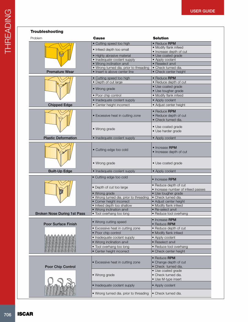
ISCAR706
THR
EA
DIN
G
ISCAR706
USER GUIDE
Troubleshooting
Problem Cause Solution• Cutting speed too high • Reduce RPM
• Infeed depth too small• Modify flank infeed• Increase depth of cut
• Highly abrasive material • Use coated grade• Inadequate coolant supply • Apply coolant• Wrong inclination anvil • Reselect anvil• Wrong turned dia. prior to threading • Check turned dia.
Premature Wear • Insert is above center line • Check center height
• Cutting speed too high • Reduce RPM• Depth of cut large • Reduce depth of cut
• Wrong grade• Use coated grade• Use tougher grade
• Poor chip control • Modify flank infeed• Inadequate coolant supply • Apply coolant
Chipped Edge • Center height incorrect • Adjust center height
• Excessive heat in cutting zone• Reduce RPM• Reduce depth of cut• Check turned dia.
• Wrong grade• Use coated grade• Use harder grade
Plastic Deformation • Inadequate coolant supply • Apply coolant
• Cutting edge too cold• Increase RPM• Increase depth of cut
• Wrong grade • Use coated grade
Built-Up Edge • Inadequate coolant supply • Apply coolant
• Cutting edge too cold• Increase RPM
• Depth of cut too large• Reduce depth of cut• Increase number of infeed passes
• Wrong grade • Use tougher grade• Wrong turned dia. prior to threading • Check turned dia.• Corner height incorrect • Adjust center height• Infeed depth too shallow • Modify flank infeed• Wrong inclination anvil • Re-select anvil
Broken Nose During 1st Pass • Tool overhang too long • Reduce tool overhang
Poor Surface Finish• Wrong cutting speed
• Increase RPM• Reduce RPM
• Excessive heat in cutting zone • Reduce depth of cut• Poor chip control • Modify flank infeed• Inadequate coolant supply • Apply coolant• Wrong inclination anvil • Reselect anvil• Tool overhang too long • Reduce tool overhang• Center height incorrect • Check center height
Poor Chip Control• Excessive heat in cutting zone
• Reduce RPM• Change depth of cut• Check turned dia.
• Wrong grade• Use coated grade• Check turned dia.• Use M-type insert
• Inadequate coolant supply • Apply coolant
• Wrong turned dia. prior to threading • Check turned dia.
Related Documents