“Complete Inspection of Friction Stir Welds in Aluminum using Ultrasonic and Eddy Current Arrays” André Lamarre 1 , Olivier Dupuis 1 and Michael Moles 2 R/D Tech ABSTRACT Ultrasonic phased-array offers tremendous advantages for the inspection of Friction stir welds (FSW), a new method of joining metals using a solid state bonding process. Phased array ultrasonics can reliably detect all internal volumetric defects in FSW, such as cracks, inclusion, porosity and lack-of-penetration. Spot-focused beams improve detection, inspection angles can be optimized electronically and electronic scan of the beam normal to the welds gives rapid one-line scan inspection to assure full coverage. Furthermore, a technique using ultrasonic attenuation measurements shows the presence or absence of conditions for forming kissing bonds (or entrapped oxide defects). Also, eddy current arrays can be used for surface inspection, and can help to detect tight kissing bonds. Using all three approaches, the overall detection capability of kissing bonds is high. INTRODUCTION TO FRICTION STIR WELDING Friction Stir Welding (FSW) is rapidly gaining acceptance in the aerospace and other industries. FSW is a new process, only having been commercialized during the 90’s. It is a solid state bonding process, which minimizes contamination. FSW is a very controllable process, and produces a very fine microstructure in the deformed region. This fine microstructure produces a higher tensile strength than other welding techniques, which permits less structural conservatism. FSW is highly repeatable, and offers other advantages like less shrinkage, no porosity, little finishing required, no gas shielding. FSW is performed using a milling-type tool, which fits into a pre-machined slot. The tool is rotated and pushed along the weld line. The two pieces of metal (usually aluminium, but possibly steel or titanium) are clamped together very firmly with a backing plate. As the milling tool pushes along the weld line, the metal is plasticized and forced around the pin. Once deformed, it rapidly cools and recrystallizes [1]. INSPECTION OF FRICTION STIR WELDS FSW have some unique features, which makes inspections more challenging. Unlike conventional welding, FSW defects can occur in principle at any orientation and any angle. In practice, most defects apparently occur along the axial and transverse axes. However, the wide range of defect orientations and skews severely complicates any NDE technique; consequently, inspection procedures are typically tailored to the actual inspection process, FSW parameters and expected defects using a Performance Demonstration approach. In general, volumetric defects like worm holes are readily detected. FSW characteristically produces tight defects, called “kissing bonds” or entrapped oxide defects. These are inherently difficult to detect by any NDE technique. Besides pulse echo ultrasonics, R/D Tech has been working with TWI as part of the Qualistir program to develop alternative inspection approaches for kissing bonds. In practice, attenuation measurements offer significant capability for reliably detecting conditions where kissing bonds may occur, though not the actual kissing bonds themselves. Additional inspections using the eddy current array probe show that kissing bonds may be detectable. However, these results are limited to one manufacturer only.

Welcome message from author
This document is posted to help you gain knowledge. Please leave a comment to let me know what you think about it! Share it to your friends and learn new things together.
Transcript
“Complete Inspection of Friction Stir Welds in Aluminum using Ultrasonic and Eddy Current Arrays”
André Lamarre1, Olivier Dupuis1 and Michael Moles2 R/D Tech
ABSTRACT
Ultrasonic phased-array offers tremendous advantages for the inspection of Friction stir welds (FSW), a new method of joining metals using a solid state bonding process. Phased array ultrasonics can reliably detect all internal volumetric defects in FSW, such as cracks, inclusion, porosity and lack-of-penetration. Spot-focused beams improve detection, inspection angles can be optimized electronically and electronic scan of the beam normal to the welds gives rapid one-line scan inspection to assure full coverage. Furthermore, a technique using ultrasonic attenuation measurements shows the presence or absence of conditions for forming kissing bonds (or entrapped oxide defects). Also, eddy current arrays can be used for surface inspection, and can help to detect tight kissing bonds. Using all three approaches, the overall detection capability of kissing bonds is high. INTRODUCTION TO FRICTION STIR WELDING
Friction Stir Welding (FSW) is rapidly gaining acceptance in the aerospace and other industries. FSW is a new process, only having been commercialized during the 90’s. It is a solid state bonding process, which minimizes contamination. FSW is a very controllable process, and produces a very fine microstructure in the deformed region. This fine microstructure produces a higher tensile strength than other welding techniques, which permits less structural conservatism. FSW is highly repeatable, and offers other advantages like less shrinkage, no porosity, little finishing required, no gas shielding.
FSW is performed using a milling-type tool, which fits into a pre-machined slot. The tool is rotated and pushed along the weld line. The two pieces of metal (usually aluminium, but possibly steel or titanium) are clamped together very firmly with a backing plate. As the milling tool pushes along the weld line, the metal is plasticized and forced around the pin. Once deformed, it rapidly cools and recrystallizes [1]. INSPECTION OF FRICTION STIR WELDS
FSW have some unique features, which makes inspections more challenging. Unlike conventional welding, FSW defects can occur in principle at any orientation and any angle. In practice, most defects apparently occur along the axial and transverse axes. However, the wide range of defect orientations and skews severely complicates any NDE technique; consequently, inspection procedures are typically tailored to the actual inspection process, FSW parameters and expected defects using a Performance Demonstration approach. In general, volumetric defects like worm holes are readily detected.
FSW characteristically produces tight defects, called “kissing bonds” or entrapped oxide defects. These
are inherently difficult to detect by any NDE technique. Besides pulse echo ultrasonics, R/D Tech has been working with TWI as part of the Qualistir program to develop alternative inspection approaches for kissing bonds. In practice, attenuation measurements offer significant capability for reliably detecting conditions where kissing bonds may occur, though not the actual kissing bonds themselves. Additional inspections using the eddy current array probe show that kissing bonds may be detectable. However, these results are limited to one manufacturer only.
From a practical inspection aspect, the FSW process generates small “lips” along either side of the OD weld line, where the milling tool deposits excess metal. These lips are typically less than 1 mm high. However, they are sufficient to hinder contact ultrasonic testing, and necessitate some form of immersion like a local water bath. The FSW metal surface finish is good compared with conventional fusion welding processes, but not up to the quality of machined surfaces.
This paper describes a comprehensive approach for detecting all defects, including kissing bonds, using
a triple NDE approach: pulse echo using optimized phased arrays; attenuation measurements (also using phased arrays); and eddy current arrays. INSPECTION TECHNIQUES
Initially, a comprehensive review of NDE techniques was performed. The wide variety of defect orientations essentially precluded any radiographic inspection techniques. Eddy current lacks the penetration to detect defects on the opposite surface, though conductivity measurements have been used to detect poor process control [2]. However, eddy current arrays offer major advantages for surface and near surface inspections, and have the advantage that no couplant is required. Conventional ultrasonics is limited in detection of defects with unusual orientations and skew, though most defects generated to date are axial or transverse. Our primary solution for NDE of FSW was ultrasonic phased arrays, which have the ability to change inspection angles and to skew the beam.
As always with solid state process like diffusion bonding and electric resistance welding, the main
concern was tight defects where bonding did not in fact occur. This indicates the need for alternative inspection approaches (in this case attenuation measurements), and the eddy current array. PHASED ARRAYS
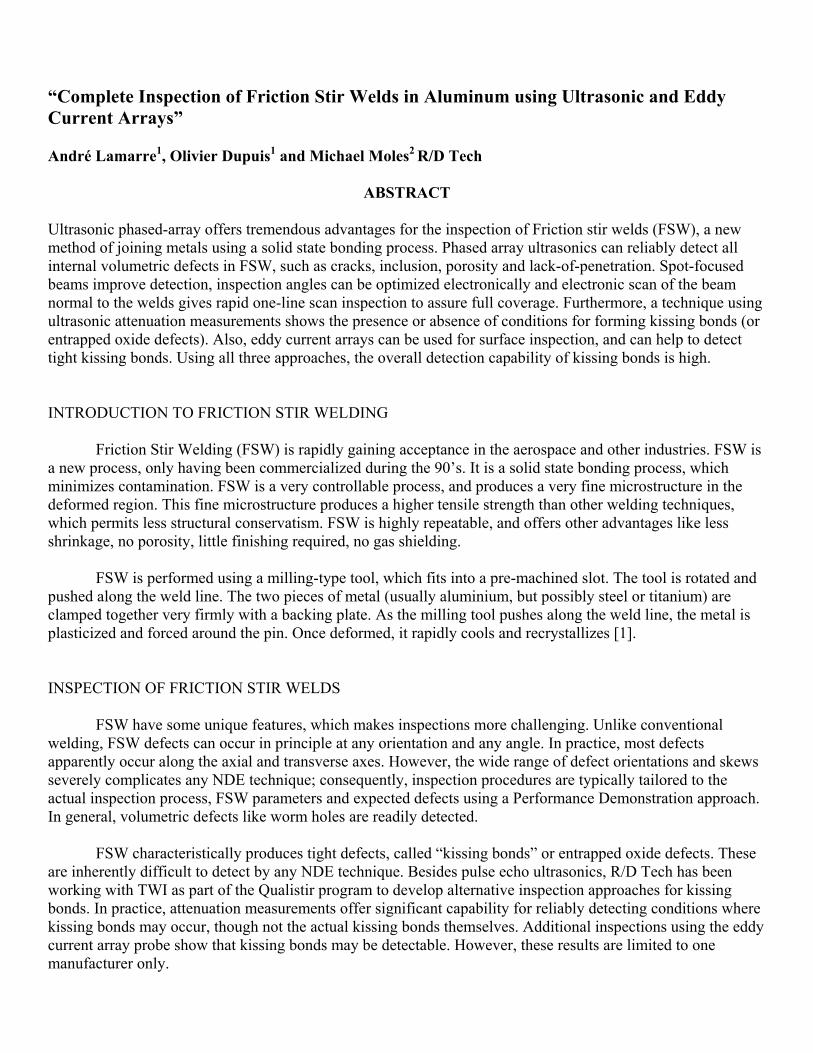
Phased arrays use an array of elements to generate an ultrasonic beam, using different time delays. The beams are formed by constructive interference [3], and can be skewed and scanned electronically. Once generated, the ultrasonic beam from a phased array is nominally identical to one generated by conventional ultrasonics.
Figure 1: Typical FSW profile and dimensions.
Phased arrays have big advantages over conventional ultrasonics in pulse echo mode: it is possible to
change angle every pulse (called sectorial or azimuthal scanning). Electronic (or linear) scanning is possible with linear and matrix arrays, where beams are rapidly scanned in a fixed pattern over a selected area. Focusing can be optimized electronically, and repeated with every set-up. With matrix arrays (or modified linear arrays), lateral scanning is possible to detect skewed defects. Dynamic depth focusing is another capability, wherein the receiver is refocused repeatedly during a single pulse to give the equivalent of multiple conventional transducers. Overall, phased arrays permit complex scans using sectorial, linear, lateral techniques; however, industrial phased arrays are typically customized to the specific application [4,5].

ULTRASONIC ATTENUATION MEASUREMENTS FOR DETECTING KISSING BONDS (ENTRAPPED OXIDE DEFECTS)
Kissing bonds mainly occur because of low penetration of the tool during the FSW process. This prevents the root region from being properly stirred (see the micrograph in Figure 2). Typically, the weld area has much finer grain size than the parent material due to the plasticizing of this are. Smaller grains mean less ultrasonic attenuation (i.e. less “noise”), and this is clearly visible on ultrasonic B-scans (see Figure 3). The principle of the signal processing is to quantify the attenuation to determine if proper mixing and FSW has occurred. While this approach does not actually detect kissing bonds, it does reliably detect the conditions under which kissing bonds occur [6].
Parent metal
Weld nugget
Figure 3: Ultrasonic scans of kissing bond. Top view (C-scan left) and side view (B-sc
array inspection results, showing less noise in the weld (M1) than the parent m EDDY CURRENT ARRAY PROBE The eddy current array probe consists of a series of individual eddy current coilspre-determined array. The coil arrangement typically permits pitch-catch axially and ciras multifrequency, absolute and differential operation. R/D Tech has developed a proprieffectively eliminates crosstalk between the coils. As a result, the EC array acts as a mulcoils, but permits unique imaging techniques like C-scans and isometrics. All the data isLissajous patterns or strip charts can be displayed. Figure 4 a) and b) below shows a typresult.
M1
M2
t
Weld rooan right) of the phased aterial (M2)
, closely packed into a cumferentially, as well etary multiplexer, which titude of individual saved, and individual ical block and scan

Figure 4: a) at left – cal block with notches and holes, with EC array poised at bottom. b) above – scan results showing C-scan, isometric and two Lissajoius patterns.
The EC array probe has major advantages: good surface and near-surface detection; defect sizing and characterization; axial vs. circumferential discrimination. However, it suffers the same limitations as other electromagnetic techniques, primarily limited penetration. EQUIPMENT AND SCANNING
To determine suitable pulse echo inspection angles, a selection of FSW plates with embedded defects is requested from the customer for inspection with appropriate thickness, welding parameters and defects (see Figure 1). This plate is inspected over a wide range of incident angles (say 35, 40, 45, 50, 55, 60, 65 and 70o) and inspection parameters to optimize detection. Axial defects can be detected using a transverse linear array and sectorial scans if requested. Calibration can be performed on a similar panel containing electro-discharge machined notches in the usual manner.
For the ultrasonic aspects of this study, an R/D Tech FOCUS phased array system is used, with
TRAKER manipulator and small water bath. Typical array is a 10 MHz linear array, with 32 active elements on a 0.31-mm pitch to give good beam steering. Since FSW is a relatively high speed process, suitable scanning speeds must be factored into the inspection process, including number of inspection angles, beam paths, quantity of data collected and display rates. Suitable samples containing kissing bonds or possible kissing bonds were also inspected using phased array attenuation measurements and the eddy current array. TYPICAL RESULTS Pulse Echo on Defect Plates
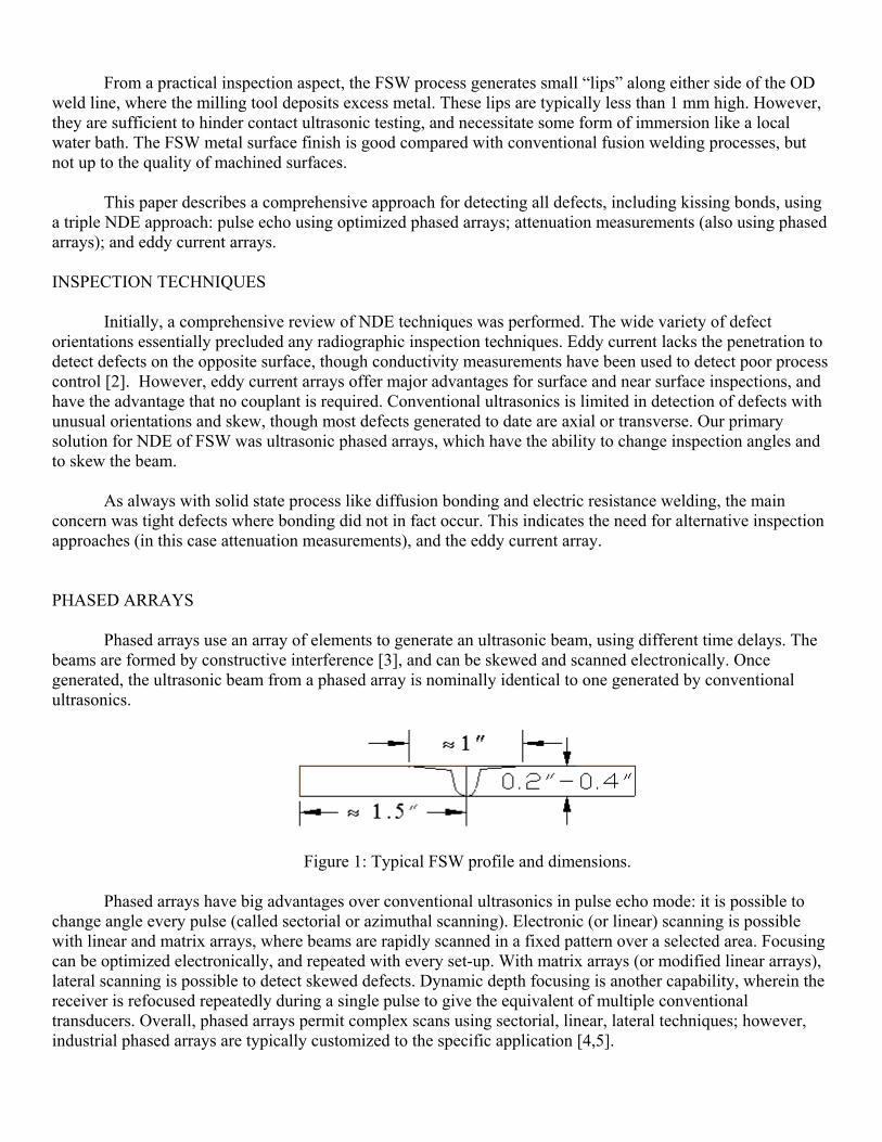
Figure 5 shows a sample scan on a transverse defect. This particular defect was best detected using a lateral scan at 0o skew and 45o refracted angle.
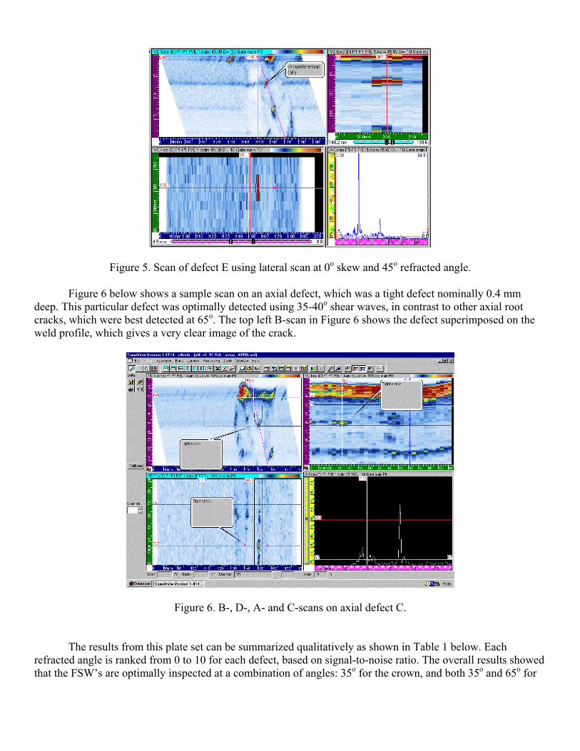
Figure 5. Scan of defect E using lateral scan at 0o skew and 45o refracted angle.
Figure 6 below shows a sample scan on an axial defect, which was a tight defect nominally 0.4 mm deep. This particular defect was optimally detected using 35-40o shear waves, in contrast to other axial root cracks, which were best detected at 65o. The top left B-scan in Figure 6 shows the defect superimposed on the weld profile, which gives a very clear image of the crack.
Figure 6. B-, D-, A- and C-scans on axial defect C.
The results from this plate set can be summarized qualitatively as shown in Table 1 below. Each refracted angle is ranked from 0 to 10 for each defect, based on signal-to-noise ratio. The overall results showed that the FSW’s are optimally inspected at a combination of angles: 35o for the crown, and both 35o and 65o for
the root. For lateral defects, the recommended inspection is a 45o incident angle, with sectorial scanning of + 30o.
Table 1. Qualitative summary of results on defects A-H
Refracted angle 35 40 45 50 55 60 65 70
Defect A side 1 2 2 5 5 10 10 10 8
Defect A side 2 4 4 4 6 8 10 10 8
Defect B side 1 2 2 2 5 5 8 8 10
Defect B side 2 2 2 2 5 5 8 8 10
Defect C side with lip
10 10 2 2 0 0 0 0
Defect C side opposite to the lip
10 8 5 5 0 0 0 0
Defects D-H for root defects
10 10 10 8 8 8 8 7
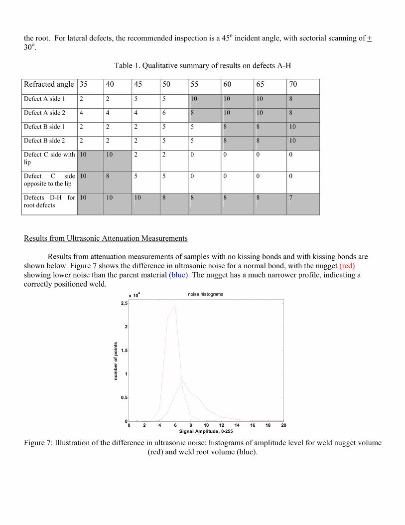
Results from Ultrasonic Attenuation Measurements Results from attenuation measurements of samples with no kissing bonds and with kissing bonds are shown below. Figure 7 shows the difference in ultrasonic noise for a normal bond, with the nugget (red) showing lower noise than the parent material (blue). The nugget has a much narrower profile, indicating a correctly positioned weld.
0 2 4 6 8 10 12 14 16 18 200
0.5
1
1.5
2
2.5x 10⁴ noise histograms
num
ber
of p
oint
s
Signal Amplitude, 0-255 Figure 7: Illustration of the difference in ultrasonic noise: histograms of amplitude level for weld nugget volume
(red) and weld root volume (blue).

When the root has been properly positioned, the ultrasonic noise level inside the root should be close to that of the weld nugget because of its small grain size. By comparing the mean level inside the root to that of the weld nugget, the operator has a powerful tool for estimating the pin penetration and therefore the probability of having kissing bonds. Figure 8 below shows a scan of sample T7 containing kissing bonds (entrapped oxide defects) all along the weld. Only a few indications can be observed by pulse echo technique (red circles).
D3 D2 D1
Figure 8: C-Scan image of FSW inspection: the plate T7 contains kissing bonds. Lower attenuation is visible all
along, while the kissing bonds only show sporadically from pulse echo.
Though a few indications can be detected at the weld root (D1 to D3), it is difficult to say whether there is a kissing bond along the full weld or not. This can be achieved by comparing the ratio M2/M1 of this plate to that of a reference plate containing no defect. The graph in Figure 9 compares two curves: the red curve represents the ratio M2/M1 of T7 sample (containing kissing bonds) and the blue curve represents the same ratio with sample T1 containing no defect.
0
0.5
1
1.5
2
2.5
3
3.5
4
4.5
5
1 17 33 49 65 81 97 113
129
145
161
177
193
209
225
241
257
273
289
Good Weld (T1)
Bad Weld (T7)
D2 D1 D3
mm of weld
Figure 9: Ratio M2/M1 along with the weld for sample of reference (blue curve) and defective sample (red
curve) containing a very tight kissing bond observed by metallography.

The mean value of the ratio M2/M1 is higher when the sample contains kissing bond defects, or potential kissing bonds. The difference in mean value between the weld nugget and the weld root was consistent for most of the samples containing kissing bonds. Figure 10 represents the value M1 and M2 for 13 samples. Sample 1 and 2 have no defects while all the other samples contain kissing bonds. For samples 1 and 2, the attenuation value of the root weld M2 is approximately equal to that of the parent metal. The higher M2 values in the other samples indicates that the root has not been properly stirred (grain size similar to the parent metal), which increases the probability of having kissing bonds.
0
1
2
3
4
5
6
7
8
1 2 3 4 5 6 7 8 9 10 11 12 13
I Weld No.
mea
n A
mpl
itude
Parent PlateWeld NuggetWeld Root
M2
M1
s
Figu Eddy current inspec Eddy current inspeckissing bonds of prtechnique used the 3 mm; lift off aligned hori
1. No defect
TWSamples without any defect
re 10: Mean signal inside the nugget
tions of Kissing Bond Panels
tions were done on four 0.8 mm (0.3epared depths of 0.75, 1.0 and 1.5 mmfollowing parameters: send/receive; a
zontally; median filter.
Samples with kissing bond
and inside the root for different samples
20”) thick panels containing no kissing bonds, and (0.030”, 0.040”and 0.060”) respectively. The
bsolute; frequency: 800 kHz; scanning resolution: 0.5 x
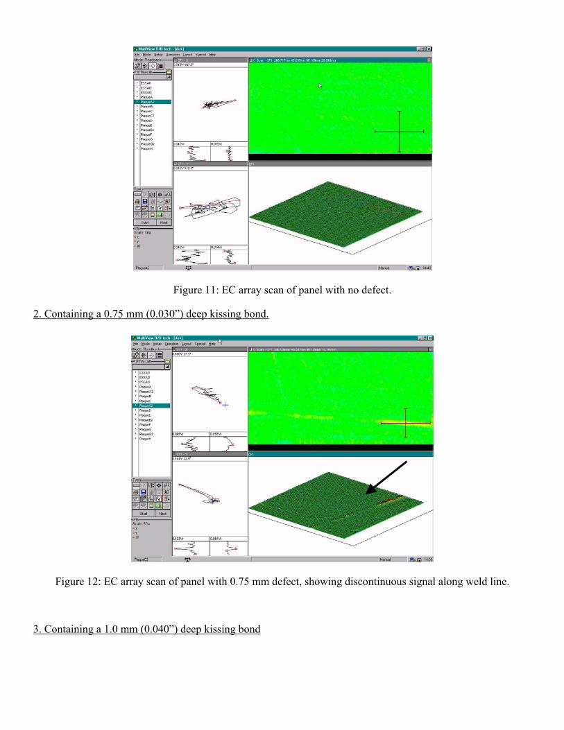
Figure 11: EC array scan of panel with no defect.
2. Containing a 0.75 mm (0.030”) deep kissing bond.
Figure 12: EC array scan of panel with 0.75 mm defect, showing discontinuous signal along weld line.
3. Containing a 1.0 mm (0.040”) deep kissing bond

Figure 13: Eddy current array scan of panel containing 1.0 mm deep kissing bond. Signal is present but not completely along the weld.
4. Containing a 1.5 mm (0.060”) deep kissing bond
Figure 14: Eddy current array scan of panel with 1.5 mm deep kissing bond. The flaw is detected easily, but the
signal amplitude is lower around the center of the weld. DISCUSSION Pulse echo inspections of FSWs can detect all volumetric-type defects and kissing bonds intermittently. Phased arrays offer the advantages of optimizing inspections, e.g. by focusing and angle selection, as well as offering high speeds. For the critical kissing bonds, a combination of attenuation methods and eddy current offer considerable detection reliability. The attenuation measurements, well grounded in physics, reliably detect the

conditions for forming kissing bonds, if not the actual defects, while eddy current appears capable of reliably detecting kissing bonds greater than 1 mm deep. However, both the attenuation measurements and the eddy current results are based on limited data samples, and need more evaluation. Overall, with three essentially independent NDE techniques, the probability of missing a significant kissing bond is very low.
CONCLUSIONS 1. Phased arrays provide a wide range of inspection angles, and detected all deliberate defects in these Friction
Stir Welds. 2. Suitable angle selection (35o for the crown and 35 & 65o for the root) maximizes Probability of Detection
for these defects for this parameter set. 3. Transverse defects can be detected using lateral and sectorial scans. 4. Electronic scanning offers the following advantages:
• It provides the coverage and speed required. • It compensates for positional errors in the delivery system. • It eliminates the need for a second mechanical axis as scanning is performed electronically.
5. Samples containing different types of defects as well as very thin kissing bonds were manufactured, and led to the development of a new processing technique based on the attenuation differences between the weld root and the weld nugget signal amplitudes.
6. Preliminary results demonstrated that this noise attenuation ratio provides a good indication of the presence of very tight kissing bonds.
7. Based on a limited sample, the eddy current array probe detects kissing bonds above ~1 mm. 8. Between the three NDE techniques (ultrasonic pulse echo, ultrasonic attenuation ratios and eddy current
array), detection of all defects including kissing bonds is highly reliable, though more evaluation needs to be performed.
REFERENCES 1. See for example, “Friction Stir Welding-Equipment”, The Welding Institute, UK,
www.twi.co.uk/bestprac/datashts/fswequip/html and “Application of Friction Stir Welding to Automotive Lightweight Structures”, The Edison Welding Institute, Columbus, Ohio, www.ewi.org/ewi/gsp/gspstir/.
2. N. Goldfine, A.P. Washabaugh and W. Arbegast, “Friction Stir Welding On-Line Process Monitoring and Post-Weld Quality Assessment with MWM-Eddy Current Sensor Arrays”, AeroMat ’99, 10th Annual Advanced Aerospace Materials & Processes, Dayton, Ohio, June 21-24, 1999.
3. G. Lafontaine and F. Cancre, “Potential of Ultrasonic Phased Arrays for Faster, Better and Cheaper Inspections”, NDT.net, vol. 5, no. 10, October 2000, www.ndt.net/article/v05n10/lafont2/lafont2.html.
4. M. Moles, E. Ginzel and N. Dubé, “Phased arrays for pipeline girth weld inspections”, Insight, vol. 44, no. 2, February 2002, p. 86.
5. M. Moles and A. Lamarre, “Phased array ultrasonic inspection of friction stir welds“, 4th International Symposium on Friction Stir Welding, Park City, Utah, USA, May 14-16, 2003.
6. C. Bird, “Quality Control of friction stir welds by the application of non-destructive testing“, 4th International Symposium on Friction Stir Welding, Park City, Utah, USA, May 14-16, 2003…

Key words: friction stir welds, ultrasonic phased arrays, attenuation measurements, eddy current arrays, “kissing bonds”

Presenting Author: Michael Moles Phone: (905) 629 0220 Fax: (905) 629 8383 E-mail: [email protected] Corresponding Author : Michael Moles
The Authors
1. André Lamarre Head, Aerospace Marketing R/D Tech 505, boul. du Parc Technologique Québec, PQ, Canada G1P 4S9 Tel : (418) 872-1155 Fax : (418) 877-0141 E-mail : [email protected] 2. Olivier Dupuis Aerospace R&D R/D Tech 505, boul. du Parc Technologique Québec, PQ, Canada G1P 4S9 Tel : (418) 872-1155 Fax : (418) 877-0141 E-mail : [email protected]
3. Michael Moles (author for correspondance) R/D Tech 5205 Tomken Road Mississauga, Ontario, Canada L4W 3N8 Tel: (905) 629-0220 Fax: (905) 629-8383 E-mail: [email protected]
Related Documents