Brigham Young University BYU ScholarsArchive All eses and Dissertations 2018-03-01 Compiler-Assisted Soſtware Fault Tolerance for Microcontrollers Mahew Kendall Bohman Brigham Young University Follow this and additional works at: hps://scholarsarchive.byu.edu/etd Part of the Electrical and Computer Engineering Commons is esis is brought to you for free and open access by BYU ScholarsArchive. It has been accepted for inclusion in All eses and Dissertations by an authorized administrator of BYU ScholarsArchive. For more information, please contact [email protected], [email protected]. BYU ScholarsArchive Citation Bohman, Mahew Kendall, "Compiler-Assisted Soſtware Fault Tolerance for Microcontrollers" (2018). All eses and Dissertations. 6724. hps://scholarsarchive.byu.edu/etd/6724

Welcome message from author
This document is posted to help you gain knowledge. Please leave a comment to let me know what you think about it! Share it to your friends and learn new things together.
Transcript
Brigham Young UniversityBYU ScholarsArchive
All Theses and Dissertations
2018-03-01
Compiler-Assisted Software Fault Tolerance forMicrocontrollersMatthew Kendall BohmanBrigham Young University
Follow this and additional works at: https://scholarsarchive.byu.edu/etd
Part of the Electrical and Computer Engineering Commons
This Thesis is brought to you for free and open access by BYU ScholarsArchive. It has been accepted for inclusion in All Theses and Dissertations by anauthorized administrator of BYU ScholarsArchive. For more information, please contact [email protected], [email protected].
BYU ScholarsArchive CitationBohman, Matthew Kendall, "Compiler-Assisted Software Fault Tolerance for Microcontrollers" (2018). All Theses and Dissertations.6724.https://scholarsarchive.byu.edu/etd/6724

Compiler-Assisted Software Fault Tolerance for Microcontrollers
Matthew Kendall Bohman
A thesis submitted to the faculty ofBrigham Young University
in partial fulfillment of the requirements for the degree of
Master of Science
Jeffrey B. Goeders, ChairMichael J. WirthlinJames K. Archibald
Department of Electrical and Computer Engineering
Brigham Young University
Copyright c© 2018 Matthew Kendall Bohman
All Rights Reserved

ABSTRACT
Compiler-Assisted Software Fault Tolerance for Microcontrollers
Matthew Kendall BohmanDepartment of Electrical and Computer Engineering, BYU
Master of Science
Commercial off-the-shelf (COTS) microcontrollers can be useful for non-critical process-ing on spaceborne platforms. Many of these microprocessors are inexpensive and consume littlepower. However, the software running on these processors is vulnerable to radiation upsets, whichcan cause unpredictable program execution or corrupt data. Space missions cannot allow theseerrors to interrupt functionality or destroy gathered data.
As a result, several techniques have been developed to reduce the effect of these upsets.Some proposed techniques involve altering the processor hardware, which is impossible for aCOTS device. Alternately, the software running on the microcontroller can be modified to de-tect or correct data corruption. There have been several proposed approaches for software miti-gation. Some take advantage of advanced architectural features, others modify software by hand,and still others focus their techniques on specific microarchitectures. However, these approachesdo not consider the limited resources of microcontrollers and are difficult to use across multipleplatforms.
This thesis explores fully automated software-based mitigation to improve the reliability ofmicrocontrollers and microcontroller software in a high radiation environment. Several difficultiesassociated with automating software protection in the compilation step are also discussed. Previ-ous mitigation techniques are examined, resulting in the creation of COAST (COmpiler-AssistedSoftware fault Tolerance), a tool that automatically applies software protection techniques to usercode. Hardened code has been verified by a fault injection campaign; the mean work to failureincreased, on average, by 21.6x. When tested in a neutron beam, the neutron cross sections ofprograms decreased by an average of 23x, and the average mean work to failure increased by5.7x.
Keywords: LLVM, TMR, DWC, software reliability, microcontroller, Texas Instruments, MSP430,ARM, radiation testing, fault injection, fault tolerance

ACKNOWLEDGMENTS
I would first l ike t o t hank m y g raduate a dvisor, D r . J eff G oeders, f or h is c ontinued men-
torship. He helped me begin on a project where I had little background knowledge, and it grew
to success with his help. He has gone above and beyond the call of duty in helping me, and I am
grateful for his help.
I would also like to thank all of the professors in the Electrical and Computer Engineering
Department who helped me develop into a better student and engineer. This is especially true of
Dr. Mike Wirthlin and Dr. James Archibald, who served as members of my graduate committee.
I am also grateful to the students of the BYU Configurable C omputing L ab f or t heir help
and support through the years. Benjamin James and Jonathan Fugal have been especially helpful
as they have worked with me on this project. They have taken a huge load off of my shoulders and
helped this project progress rapidly.
Of course, I am indebted for the love and support of the many members of my family. I
cannot list all of them, but I am indebted to them. A special thank you goes to my wonderful
parents who have always stood by me and encouraged me throughout my schooling. My uncle
Scott has also helped guide me and inspired me onto this career path. Finally, thank you to
my wonderful wife, Rachel, who has inspired and aided me through countless late nights and
early mornings. Thank you.
This work was supported by the Los Alamos Neutron Science Center (LANSCE) which
provided neutron beam time under proposal NS-2017-7574-F. This work was also supported by
the I/UCRC Program of the National Science Foundation under Grant No. 1738550 through the
NSF Center for High-Performance Reconfigurable Computing (CHREC).

TABLE OF CONTENTS
List of Tables . . . . . . . . . . . . . . . . . . . . . . . . . . . . . . . . . . . . . . . . . . vi
List of Figures . . . . . . . . . . . . . . . . . . . . . . . . . . . . . . . . . . . . . . . . . vii
Chapter 1 Introduction . . . . . . . . . . . . . . . . . . . . . . . . . . . . . . . . . . . 11.1 Thesis Contributions . . . . . . . . . . . . . . . . . . . . . . . . . . . . . . . . . 31.2 Thesis Organization . . . . . . . . . . . . . . . . . . . . . . . . . . . . . . . . . . 4
Chapter 2 Background and Related Work . . . . . . . . . . . . . . . . . . . . . . . . 62.1 Single Event Effects . . . . . . . . . . . . . . . . . . . . . . . . . . . . . . . . . . 62.2 Software Mitigation Techniques . . . . . . . . . . . . . . . . . . . . . . . . . . . 8
2.2.1 Data Flow Protection . . . . . . . . . . . . . . . . . . . . . . . . . . . . . 92.2.2 Control Flow Protection . . . . . . . . . . . . . . . . . . . . . . . . . . . 132.2.3 Automated Software Mitigation Tools . . . . . . . . . . . . . . . . . . . . 16
2.3 LLVM Compiler Architecture . . . . . . . . . . . . . . . . . . . . . . . . . . . . . 172.4 Chapter Summary . . . . . . . . . . . . . . . . . . . . . . . . . . . . . . . . . . . 18
Chapter 3 COAST: Compiler-Assisted Software Fault Tolerance . . . . . . . . . . . 193.1 Basic COAST Protections . . . . . . . . . . . . . . . . . . . . . . . . . . . . . . . 19
3.1.1 Overview . . . . . . . . . . . . . . . . . . . . . . . . . . . . . . . . . . . 203.1.2 Duplicate with Compare . . . . . . . . . . . . . . . . . . . . . . . . . . . 213.1.3 Triple Modular Redundancy . . . . . . . . . . . . . . . . . . . . . . . . . 223.1.4 Control Flow Protection . . . . . . . . . . . . . . . . . . . . . . . . . . . 24
3.2 Configuration Options . . . . . . . . . . . . . . . . . . . . . . . . . . . . . . . . . 253.2.1 Replication Rules . . . . . . . . . . . . . . . . . . . . . . . . . . . . . . . 273.2.2 Replication Scope . . . . . . . . . . . . . . . . . . . . . . . . . . . . . . . 283.2.3 Error Logging . . . . . . . . . . . . . . . . . . . . . . . . . . . . . . . . . 293.2.4 Input Initialization . . . . . . . . . . . . . . . . . . . . . . . . . . . . . . 303.2.5 Interleaving . . . . . . . . . . . . . . . . . . . . . . . . . . . . . . . . . . 303.2.6 Other Options . . . . . . . . . . . . . . . . . . . . . . . . . . . . . . . . . 31
3.3 Challenges and Limitations of Automated Protection . . . . . . . . . . . . . . . . 313.3.1 Challenges . . . . . . . . . . . . . . . . . . . . . . . . . . . . . . . . . . 323.3.2 Limitations . . . . . . . . . . . . . . . . . . . . . . . . . . . . . . . . . . 34
3.4 Validation . . . . . . . . . . . . . . . . . . . . . . . . . . . . . . . . . . . . . . . 363.5 Running COAST . . . . . . . . . . . . . . . . . . . . . . . . . . . . . . . . . . . 373.6 Chapter Summary . . . . . . . . . . . . . . . . . . . . . . . . . . . . . . . . . . . 38
Chapter 4 Fault Injection Testing . . . . . . . . . . . . . . . . . . . . . . . . . . . . . 394.1 Approach . . . . . . . . . . . . . . . . . . . . . . . . . . . . . . . . . . . . . . . 394.2 Target Device . . . . . . . . . . . . . . . . . . . . . . . . . . . . . . . . . . . . . 404.3 Fault Injection Framework . . . . . . . . . . . . . . . . . . . . . . . . . . . . . . 414.4 Benchmarks . . . . . . . . . . . . . . . . . . . . . . . . . . . . . . . . . . . . . . 44
iv

4.5 Metrics . . . . . . . . . . . . . . . . . . . . . . . . . . . . . . . . . . . . . . . . 454.6 Results . . . . . . . . . . . . . . . . . . . . . . . . . . . . . . . . . . . . . . . . . 46
4.6.1 Effect of Configurations . . . . . . . . . . . . . . . . . . . . . . . . . . . 464.6.2 Benchmark Characteristics . . . . . . . . . . . . . . . . . . . . . . . . . . 52
4.7 Chapter Summary . . . . . . . . . . . . . . . . . . . . . . . . . . . . . . . . . . . 53
Chapter 5 Radiation Testing . . . . . . . . . . . . . . . . . . . . . . . . . . . . . . . . 545.1 Goals of Radiation Testing . . . . . . . . . . . . . . . . . . . . . . . . . . . . . . 545.2 Test Setup . . . . . . . . . . . . . . . . . . . . . . . . . . . . . . . . . . . . . . . 545.3 Metrics . . . . . . . . . . . . . . . . . . . . . . . . . . . . . . . . . . . . . . . . 585.4 Results . . . . . . . . . . . . . . . . . . . . . . . . . . . . . . . . . . . . . . . . . 60
5.4.1 Comparison with Previous Work . . . . . . . . . . . . . . . . . . . . . . . 635.5 Chapter Summary . . . . . . . . . . . . . . . . . . . . . . . . . . . . . . . . . . . 66
Chapter 6 Conclusion . . . . . . . . . . . . . . . . . . . . . . . . . . . . . . . . . . . 676.1 Future Work . . . . . . . . . . . . . . . . . . . . . . . . . . . . . . . . . . . . . . 68
References . . . . . . . . . . . . . . . . . . . . . . . . . . . . . . . . . . . . . . . . . . . 70
Appendix A Code Listings . . . . . . . . . . . . . . . . . . . . . . . . . . . . . . . . . . 74
v
LIST OF TABLES
2.1 Rules for data flow protection [1] . . . . . . . . . . . . . . . . . . . . . . . . . . . . 11
3.1 Rules for data flow protection [1]. . . . . . . . . . . . . . . . . . . . . . . . . . . . . 263.2 Pass command line configuration options. . . . . . . . . . . . . . . . . . . . . . . . . 273.3 Potential solutions to challenges with automated replication. . . . . . . . . . . . . . . 353.4 COAST protections. . . . . . . . . . . . . . . . . . . . . . . . . . . . . . . . . . . . . 37
4.1 Averaged fault injection results, relative to unmitigated versions . . . . . . . . . . . . 474.2 Summary of results after 5,000 fault injections for each benchmark. . . . . . . . . . . 49
5.1 Radiation test benchmark characteristics. . . . . . . . . . . . . . . . . . . . . . . . . . 615.2 Program results from neutron beam test. . . . . . . . . . . . . . . . . . . . . . . . . . 615.3 Reliability results from neutron beam test. . . . . . . . . . . . . . . . . . . . . . . . . 62
vi

LIST OF FIGURES
2.1 Taxonomy of how SEUs affect microprocessors [2]. . . . . . . . . . . . . . . . . . . . 72.2 Categorization of how timing affects SEUs [3]. . . . . . . . . . . . . . . . . . . . . . 82.3 Code that has been modified by EDDI [4]. . . . . . . . . . . . . . . . . . . . . . . . . 102.4 Code that has been modified by SWIFT-R. . . . . . . . . . . . . . . . . . . . . . . . . 132.5 Example of CFCSS, after [5]. . . . . . . . . . . . . . . . . . . . . . . . . . . . . . . . 142.6 Diagram of the LLVM compilation flow. . . . . . . . . . . . . . . . . . . . . . . . . . 17
3.1 DWC-based fault detection code. . . . . . . . . . . . . . . . . . . . . . . . . . . . . . 213.2 TMR based fault correction code. . . . . . . . . . . . . . . . . . . . . . . . . . . . . . 233.3 CFCSS-based fault detection code. . . . . . . . . . . . . . . . . . . . . . . . . . . . . 253.4 Using the -reportErrors flag. . . . . . . . . . . . . . . . . . . . . . . . . . . . . . . . 293.5 Default code and interleaved code. . . . . . . . . . . . . . . . . . . . . . . . . . . . . 313.6 Calling protected functions from other functions. . . . . . . . . . . . . . . . . . . . . 323.7 Calling unprotected functions from protected functions. . . . . . . . . . . . . . . . . . 333.8 Example of code with double indirection. . . . . . . . . . . . . . . . . . . . . . . . . 363.9 Command line directions to run the COAST tool. . . . . . . . . . . . . . . . . . . . . 38
4.1 The MSP430FR5969 LaunchPad development board [6]. . . . . . . . . . . . . . . . . 404.2 FIJI supporting header file. . . . . . . . . . . . . . . . . . . . . . . . . . . . . . . . . 424.3 Averaged fault injection results . . . . . . . . . . . . . . . . . . . . . . . . . . . . . . 484.4 MWTF across benchmarks and configurations. . . . . . . . . . . . . . . . . . . . . . . 52
5.1 Picture of MSP430 boards at LANSCE neutron test. . . . . . . . . . . . . . . . . . . . 555.2 Diagram of the radiation test setup. . . . . . . . . . . . . . . . . . . . . . . . . . . . . 565.3 Picture of LANSCE neutron test. The MSP430 boards are in the foreground. . . . . . . 575.4 Radiation test matrix multiplication benchmark. . . . . . . . . . . . . . . . . . . . . . 595.5 Design cross sections. . . . . . . . . . . . . . . . . . . . . . . . . . . . . . . . . . . . 635.6 Comparison between Trikaya and COAST. . . . . . . . . . . . . . . . . . . . . . . . . 645.7 Comparison between DWCF and COAST. . . . . . . . . . . . . . . . . . . . . . . . . 65
A.1 CRC benchmark. . . . . . . . . . . . . . . . . . . . . . . . . . . . . . . . . . . . . . 74A.2 Matrix multiplication benchmark. . . . . . . . . . . . . . . . . . . . . . . . . . . . . 75A.3 Quicksort benchmark. . . . . . . . . . . . . . . . . . . . . . . . . . . . . . . . . . . . 76A.4 Radiation test supporting header file. . . . . . . . . . . . . . . . . . . . . . . . . . . . 77
vii
CHAPTER 1. INTRODUCTION
As space exploration continues to be a topic of interest for both governmental and indus-
trial entities, the need for reliable computing in high-radiation environments increases. Radiation-
hardened microprocessors tend to have reduced performance due to the older manufacturing tech-
nologies used [2]. Commercial off-the-shelf (COTS) microprocessors tend to be cheaper, smaller,
faster, and take less power than these radiation-hardened processors. Simple microcontrollers are
especially attractive for non-mission-critical processing, such as configuration and monitoring,
because of their low cost and power requirements [7]. However, they are vulnerable to radiation-
induced upsets that can suddenly change the state of the processor. This can lead to any number of
irregular behaviors, such as crashes or incorrect computations [2].
Ionizing radiation can cause a change in the state of a struck transistor [8]. Unfortunately,
as manufacturing technologies advance, transistors become easier to upset because they are more
sensitive to small changes in charge. Although the smaller size makes the probability of upsetting
an individual transistor less likely, the higher transistor counts per die offset this reduction. The
ongoing trend of using smaller transistor sizes, more transistors per die, and more complex design
components continues to increase the probability of a fault in an integrated circuit [9].
These faults can come in several different forms. Broadly speaking, they are referred to
as single event effects (SEEs). These range from flipped bits in memory to destructive latchups
that can destroy an integrated circuit [7]. The European Space Agency (ESA) has said that SEEs
are “of major concern for space applications. If not handled well SEEs can lead to, in worst case,
catastrophic damage on space crafts” [10].
One form of SEE is silent data corruption (SDC). SDC occurs when stored data is altered
by radiation-induced bit flips. The modified data value can be used in later computations, causing
incorrect results without any indication of a problem. Alternately, the altered value could cause the
program to execute incorrectly or hang. In order to use COTS microprocessors in high-radiation
1

environments, some form of SDC mitigation must be implemented. Since modifying the hardware
of COTS microcontrollers is impossible for the end user, the software can be modified to be less
susceptible to faults.
Many previous works target higher-end processors [11], [12] which can use advanced fea-
tures to mask the overhead associated with software fault tolerance. This work focuses on less
powerful microcontrollers, which require a slightly different approach because of the limited re-
sources available. For example, there is an assumption in many software fault mitigation works
that the system memory has some form of correction, such as error correcting codes (ECC) [13].
This is not true for many microcontrollers. For instance, the MSP430FR59xx series [14], which
has been used in previous radiation tests [15], and which we target in our experiments, does not
have any form of SEU protection applied to the memory. Additionally, many forms of error de-
tection rely on more sophisticated architectural features to mask protection overheads or create
new methods entirely. For example, Oh et al. use superscalar execution to reduce the overhead
of redundant calculations [11], Didehban et al. utilize load/store queue forwarding to reduce the
memory traffic [13], and Rebaudengo et al. rely on a rollback scheme to enable fault recovery [16].
Microcontrollers lack such features, so more general fault mitigation techniques must be used.
There are two places where software fault tolerance can be applied. The first is the data flow
of the program. This is a general term used to describe the movement of data within the processor
and memory. Protecting the data flow means ensuring that all program variables have the proper
values. There are a host of different solutions, all with slightly varying purposes and approaches.
A popular approach is to repeatedly perform a calculation, then compare all of the results to ensure
they are the same. If they are different, an upset has occurred. Some forms of data flow protection
simply detect errors [4], [11], but others provide a mechanism for data correction [15], [17], [18].
Data flow protection using redundant calculations can be either coarse-grained or fine-
grained. Coarse-grained mitigation occurs at a higher level. Entire subroutine calls are replicated,
and the results are compared. Fine-grained mitigation, on the other hand, takes place at the instruc-
tion level. Each computation instruction is replicated; then the results are periodically compared.
Fine-grained mitigation comes at a higher overhead in runtime and code size, but has lower fault
detection latency [11] and may be more tolerant to multiple upsets.
2

The second target for software fault tolerance is the control flow of the program, which is
the ordering of instructions in the program. It can be corrupted if an upset occurs in the program
counter, program stack, or any value that affects the direction of the branch. There are several pro-
posed solutions to check for control flow errors. Restoring the correct processor state is generally
not possible, so the processor is reset after errors. Control flow protection methods, when used, are
typically paired with data flow protection methods [4], [19].
These techniques may involve heavy modification of the source code. This has occasionally
been done by hand in previous works [15], [18]. However, this is a laborious process that is
subject to human error. Key parts of the program could be missed, mitigation could be applied
incorrectly, or the program could simply be too large to be feasibly modified by hand. To combat
these problems, two categories of tools have been developed. One approach is to generate the
assembly code for a target, then process and rewrite the code [8]. Alternately, other tools [4]
[20] have applied protection by modifying a compiler to insert the applicable techniques in the
compilation process.
There are a number of shortcomings with previous work on software mitigation. First,
some approaches involve hand-modified code, which is impractical for large programs. It is also
error-prone. Many existing solutions have leveraged advanced architectural features which are
not generally available. Other tools target specific hardware architectures. Finally, none of the
previously mentioned software mitigation tools are openly available to other researchers. The
purpose of this thesis is to provide an automatic software mitigation platform that is robust, flexible,
and publicly available.
1.1 Thesis Contributions
This thesis introduces COAST (COmpiler-Assisted Software fault Tolerance), a new tool
for automated fine-grained software-based fault mitigation using the LLVM compiler infrastruc-
ture [21]. Through this tool we explore several data flow and control flow protection options based
on previously tested techniques [22]–[24]. While many of these techniques have been explored in
individual works, we incorporate several into a single tool, allowing us to easily compare different
techniques. These passes are highly customizable and can be controlled using in-code directives
3

or command line flags. In pursuit of this tool, a number of other areas of interest have emerged.
These are presented as additional contributions:
• Several challenges with automating protection are addressed which have not been docu-
mented in prior work. These challenges are discussed along with the implemented solutions.
• In order to evaluate the effectiveness of automated protection, a fault injection tool designed
to work with Texas Instruments Launchpad MSP430 and ARM development boards has been
developed. This tool was used to test the fault tolerance of software hardened by COAST.
• The fault injection approach, as well as the results of different configurations of protection
techniques, are given. When tested on an MSP430 microcontroller, modified code shows
increases in reliability up to 22x, similar to the state of the art [1].
• Mitigated code was also tested on an MSP430 microcontroller in a neutron beam to deter-
mine its fault tolerance in a highly radioactive environment. The setup for this test and the
results are both provided. Code modified by COAST shows reliability improvements of up
to 7x, which is similar to the state of the art [18], [25].
• The work presented in this thesis has been accepted for presentation in the Silicon Errors
in Logic – System Effects (SELSE) workshop. Additionally, it has accepted as a poster
presentation in the IEEE Nuclear and Space Radiation Effects Conference (NSREC).
1.2 Thesis Organization
The remainder of this thesis is outlined as follows. Chapter 2 provides a general background
for this work. This includes an introduction to the effects of radiation on program execution.
Afterwards, different forms of error mitigation are presented to protect both control flow and data
flow. Finally, various existing automated software protection tools are described.
Chapter 3 details the main contribution of this work, the exploration of automated software
mitigation and the associated tool. The tool’s functionality, examples, and challenges are all de-
scribed in this chapter. Chapter 4 documents a fault injection tool developed for this project, as well
4

as results from a fault injection campaign performed on mitigated software. Chapter 5 presents re-
sults obtained from testing hardened software in a neutron beam at Los Alamos Neutron Science
Center (LANSCE). Finally, Chapter 6 concludes the thesis and discusses future work.
5

CHAPTER 2. BACKGROUND AND RELATED WORK
This chapter introduces the background knowledge necessary for this thesis. The effects of
radiation on microprocessors are first presented. Next, different forms of software fault tolerance
are discussed, as well as several tools that automatically apply fault tolerance. Finally, the LLVM
compiler infrastructure is presented.
2.1 Single Event Effects
Single event effects occur when ionizing radiation interacts with circuits. A transistor
struck by charged particles can flip states without any indication of an upset. This is known as
a single event effect (SEE) [26]. SEEs can cause hard errors, which can permanently destroy the
affected component. Soft errors, where the SEE is non-destructive, are more common. This work
focuses on mitigating the effects of soft errors.
Although transistor size is shrinking, the probability of SEEs occurring has actually in-
creased as explained by Quinn et al. [9]. Smaller transistors operate at lower voltages, so induced
changes have a higher chance of upsetting the transistor. Additionally, systems continually get
larger and more complex as the transistor size shrinks. All of these effects combine to make soft
errors more common in high radiation environments.
There are three main types of soft errors that can occur [10]:
• Single Event Upsets (SEU): An SEU occurs when a memory cell or register changes state.
• Single Event Functional Interrupt (SEFI): A SEFI is a SEE that leads to temporary loss
of device functionality. It can be removed by resetting or power cycling the board. SEFIs
are often caused by SEUs in system control registers.
6

• Single Event Transient (SET): SETs arise when there are momentary upsets in combina-
tional logic, creating a glitch. This glitch can cause other errors if it is captured in a memory
element.
When an SEU occurs within a microprocessor, there are three categorizations of the pos-
sible result [27]. The first is a fault, which is the result of an SEU where a bit was flipped. This
fault could become an error if the fault is activated, meaning that the fault is observable by the
system. The error results in a failure when the system deviates from specification. Not all faults
cause errors, and not all errors cause failures.
Figure 2.1: Taxonomy of how SEUs affect microprocessors [2].
SEUs in microprocessors can cause a number of effects. Figure 2.1 contains a taxonomy
of the components that can be affected by SEUs [2]. SEUs can affect the cache/memory, registers,
and the processor control logic. The general consequences of an upset are in the darker boxes at
the bottom of the chart. Many of these, such as a program exception or crash, cause execution
to fail and would be considered a SEFI. SDC stems from corrupted data values. This can happen
directly, when the datum itself is altered, or indirectly, when the program execution is modified.
The timing of the SEU dictates if a SEU-induced fault results in a failure. Figure 2.2
illustrates different possibilities depending on when the fault is detected [3]. If a corrupted value
7
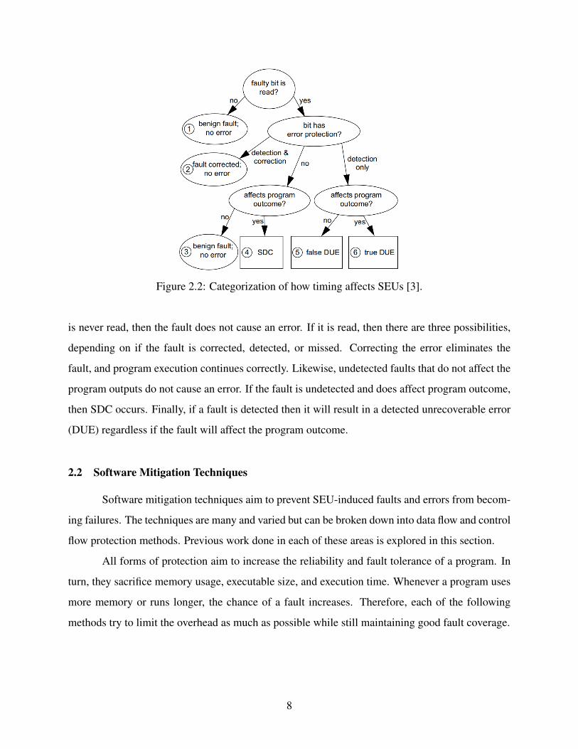
Figure 2.2: Categorization of how timing affects SEUs [3].
is never read, then the fault does not cause an error. If it is read, then there are three possibilities,
depending on if the fault is corrected, detected, or missed. Correcting the error eliminates the
fault, and program execution continues correctly. Likewise, undetected faults that do not affect the
program outputs do not cause an error. If the fault is undetected and does affect program outcome,
then SDC occurs. Finally, if a fault is detected then it will result in a detected unrecoverable error
(DUE) regardless if the fault will affect the program outcome.
2.2 Software Mitigation Techniques
Software mitigation techniques aim to prevent SEU-induced faults and errors from becom-
ing failures. The techniques are many and varied but can be broken down into data flow and control
flow protection methods. Previous work done in each of these areas is explored in this section.
All forms of protection aim to increase the reliability and fault tolerance of a program. In
turn, they sacrifice memory usage, executable size, and execution time. Whenever a program uses
more memory or runs longer, the chance of a fault increases. Therefore, each of the following
methods try to limit the overhead as much as possible while still maintaining good fault coverage.
8

2.2.1 Data Flow Protection
Many methods of data flow protection are available. All of these forms rely on some
form of spatial or temporal redundancy to protect data as it is moved and updated during normal
program execution. Data is stored at different locations and updated at different times, reducing
the probability that a radiation-induced upset will corrupt the data. These approaches all increase
the latency of the program. This may break specifications, so it is not always feasible to use these
techniques. This thesis focuses on improving the reliability of software, but there are other factors
that must be considered for different target applications.
One approach, AN-encoding, is a form of data protection using arithmetic codes [12]. Each
datum is multiplied by a constant A. Data must be divisible by A to be valid, so every operation
must preserve this trait. In an AN-encoded system, the variables must be periodically checked by
testing if the datum is equal to zero modulus A. If it is not, then an error occurred. This model relies
heavily on correct arithmetic operations, which, if done improperly, causes the code to fail. AN-
encoding shows roughly 95% fault coverage using 128-bit instruction extensions and Streaming
SIMD Extensions (SEE). AN-encoding would be difficult to do on a microcontroller because of
the overhead associated with many modulus operations.
EDDI (Error Detection by Duplicated Instructions) [11] is a popular data flow protection
approach. EDDI applies fine-grained mitigation, duplicating each computation instruction. The
duplicates are periodically compared with the original data to detect a mismatch. A detected error
triggers some form of user-specified error handler. The purpose is to detect SDC and then stop the
processor. This approach is known as duplicate with compare (DWC). The copies are checked in
two different scenarios:
• Before the program stores data. EDDI assumes that a program has run correctly if the stores
have all executed properly.
• Before the processor executes all branch instructions. A branch instruction inherently oper-
ates on the result of a single comparison. In order to reduce the chances of bad data causing
erratic code flow, the relevant variable is checked against its duplicate before the branch
condition executes.
9
l d r12 = [GLOBAL]
r11 = add r12 , r13
s t m[ r11 ] = r12
(a) Original Code
l d r12 = [GLOBAL]ld r22 = [GLOBAL+offset]r11 = add r12 , r13r21 = add r22, r23p1 = cmp neq r11, r21p2 = cmp neq r12, r22p1 = or p1, p2br (p1) faultDetecteds t m[ r11 ] = r12st m[r21+offset] = r22
(b) EDDI code
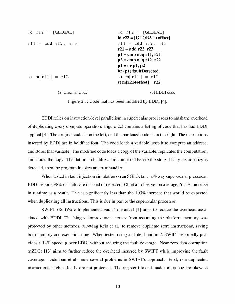
Figure 2.3: Code that has been modified by EDDI [4].
EDDI relies on instruction-level parallelism in superscalar processors to mask the overhead
of duplicating every compute operation. Figure 2.3 contains a listing of code that has had EDDI
applied [4]. The original code is on the left, and the hardened code is on the right. The instructions
inserted by EDDI are in boldface font. The code loads a variable, uses it to compute an address,
and stores that variable. The modified code loads a copy of the variable, replicates the computation,
and stores the copy. The datum and address are compared before the store. If any discrepancy is
detected, then the program invokes an error handler.
When tested in fault injection simulation on an SGI Octane, a 4-way super-scalar processor,
EDDI reports 98% of faults are masked or detected. Oh et al. observe, on average, 61.5% increase
in runtime as a result. This is significantly less than the 100% increase that would be expected
when duplicating all instructions. This is due in part to the superscalar processor.
SWIFT (SoftWare Implemented Fault Tolerance) [4] aims to reduce the overhead asso-
ciated with EDDI. The biggest improvement comes from assuming the platform memory was
protected by other methods, allowing Reis et al. to remove duplicate store instructions, saving
both memory and execution time. When tested using an Intel Itanium 2, SWIFT reportedly pro-
vides a 14% speedup over EDDI without reducing the fault coverage. Near zero data corruption
(nZDC) [13] aims to further reduce the overhead incurred by SWIFT while improving the fault
coverage. Didehban et al. note several problems in SWIFT’s approach. First, non-duplicated
instructions, such as loads, are not protected. The register file and load/store queue are likewise
10
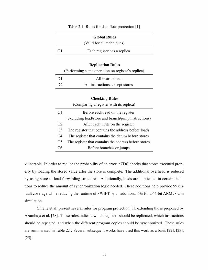
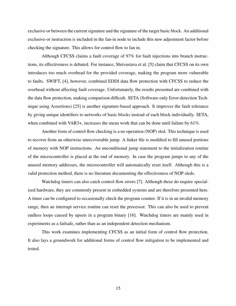
Table 2.1: Rules for data flow protection [1]
Global Rules(Valid for all techniques)
G1 Each register has a replica
Replication Rules(Performing same operation on register’s replica)
D1 All instructionsD2 All instructions, except stores
Checking Rules(Comparing a register with its replica)
C1 Before each read on the register(excluding load/store and branch/jump instructions)
C2 After each write on the registerC3 The register that contains the address before loadsC4 The register that contains the datum before storesC5 The register that contains the address before storesC6 Before branches or jumps
vulnerable. In order to reduce the probability of an error, nZDC checks that stores executed prop-
erly by loading the stored value after the store is complete. The additional overhead is reduced
by using store-to-load forwarding structures. Additionally, loads are duplicated in certain situa-
tions to reduce the amount of synchronization logic needed. These additions help provide 99.6%
fault coverage while reducing the runtime of SWIFT by an additional 5% for a 64-bit ARMv8-a in
simulation.
Chielle et al. present several rules for program protection [1], extending those proposed by
Azambuja et al. [28]. These rules indicate which registers should be replicated, which instructions
should be repeated, and when the different program copies should be synchronized. These rules
are summarized in Table 2.1. Several subsequent works have used this work as a basis [22], [23],
[25].
11
Rule G1 simply means that every datum stored has replicas in processor registers. This
is true for all combinations of rules. Rule D1 dictates that all instructions should be replicated,
whereas D2 specifies that store operations should not be. When store instructions are replicated,
each variable has a duplicate value in memory. This is useful when the system does not have
memory protection like error correcting codes (ECC). This may often be the case for COTS mi-
crocontrollers, which are the focus of this work. However, replicating stores comes with a greater
memory and performance overhead. The different checking rules dictate when the data streams
should be compared. Chielle et al. determine that rules G1, D2, C3, C4, C5, and C6 combine to
provide the most reliability for the lowest overhead [1]. This combination is referred to as VAR3+.
VAR3+ provides 95% fault coverage at a cost of 75% increase in execution time and an 80%
increase in memory usage when simulated on a miniMIPS microprocessor.
Unlike the previous examples, SWIFT-R [17] does not rely on duplication. Instead, it uses
a form of triple modular redundancy (TMR), which triplicates instructions. TMR represents a
different approach than DWC. Instead of detecting SDC and halting to avoid SDC, TMR attempts
to tolerate SDC and continue running. Additionally, DWC checking points are replaced by a voting
mechanism that allows the program to correct errors and continue normal execution. The majority
voting routine takes the most common value in the three copies of the register then sets all of
the registers to that value. Triplication, of course, introduces even larger overheads in terms of
program size, memory usage, and runtime. SWIFT-R introduces a 99% increase in execution time
for 97.3% fault coverage on a PowerPC 970. An example of code modified by SWIFT-R is found
in Figure 2.4. The inserted code is in bold. This is the same basic code used to illustrate DWC; it
loads a value, uses it to compute an address, then stores the contents of a register in that location.
The Trikiya approach [18] is another example of TMR-based protection. However, instead
of fine-grained replication, Trikiya works at the coarse-grained level. Entire subroutines are ex-
ecuted multiple times instead of individual instructions. Hand-mitigated code emulating Trikaya
was tested on several different microcontrollers in a neutron beam. The memory usage increase on
an MSP430FR5739 varied between 26% and 140% and had a time overhead of between 46% and
250%. However, the authors did not observe any errors in their mitigated code.
Additionally, the probability of a fault occurring in TMR is explored by Quinn et al. [18].
The voting mechanism used in TMR simply chooses the most common result. If all copies of
12

l d r3 = [ r4 ]
add r1 = r2 , r3
s t [ r1 ] = r2
(a) Original Code
majority(r4,r4′,r4′′)l d r3 = [ r4 ]mov r3′ = r3mov r3′′= r3add r1 = r2 , r3add r1′ = r2′,r3′add r1′′=r2′′,r3′′majority(r1,r1′,r1′′)majority(r2,r2′,r2′′)s t [ r1 ] = r2
(b) SWIFT-R code [17]
Figure 2.4: Code that has been modified by SWIFT-R.
the variable are different then the mitigated software could still fail. TMR, then, cannot function
properly when two upsets affect multiple copies of the same variable. The probability of this
occurring is given in Equation 2.1 [18]. In this equation each redundant variable is n words long
in a memory containing m words.
P(T MRFailure) =3nm
2nm
(2.1)
As the size of each variable increases, the probability of two upsets affecting replicas of the same
variable increase. This leads to the conclusion that, as a general rule of thumb, the execution speed
of the mitigated program must be faster than twice the upset rate to make a TMR error unlikely [18].
This work explores the implementation of both DWC and TMR in software as forms of data flow
protection.
2.2.2 Control Flow Protection
Control flow protection ensures that the program executes all instructions in the proper
order. This is necessary because the program counter, function return addresses, and branch in-
structions introduce single points of failure where SDC can corrupt program execution. Control
flow mitigation ensures that the transitions into and out of code regions are legal, and reports an er-
13

ror if an unexpected or illegal transition occurs. These code regions are referred to as basic blocks,
which are defined to be sections of code with single entry and exit points.
Figure 2.5: Example of CFCSS, after [5].
Control flow checking via software signatures (CFCSS) [24] requires each basic block to
have a unique signature value, assigned in compilation. This is illustrated in Figure 2.5. In compi-
lation, each basic block is assigned a static signature s and associated signature difference d. This
difference is calculated by taking the bitwise exclusive-or (XOR) of the current block’s signature
and its successor. When the program is run, a register G keeps track of the current signature.
Whenever a new basic block is entered, the signature tracker is XORd with the difference, which
should then equal the basic block signature. Equation 2.2 illustrates this property when transition-
ing from basic block 1 to basic block 2. The symbol ⊕ is used to show the XOR operation. If G
does not equal s2, then a control flow error has occurred. Program execution is then handed off to
an error handler.
Gnew = G⊕d2 = s1⊕ (s1⊕ s2) = s2 (2.2)
More complicated control flow can cause CFCSS to fail. Specifically, it is impossible to
have a single static signature adjustment factor when multiple basic blocks can fan in to the same
basic block. When this is the case, a runtime signature adjustment factor D is defined to be the
14
exclusive-or between the current signature and the signature of the target basic block. An additional
exclusive-or instruction is included in the fan-in node to include this new adjustment factor before
checking the signature. This allows for control flow to fan in.
Although CFCSS claims a fault coverage of 97% for fault injections into branch instruc-
tions, its effectiveness is debated. For instance, Shrivastava et al. [5] claim that CFCSS on its own
introduces too much overhead for the provided coverage, making the program more vulnerable
to faults. SWIFT, [4], however, combined EDDI data flow protection with CFCSS to reduce the
overhead without affecting fault coverage. Unfortunately, the results presented are combined with
the data flow protection, making comparison difficult. SETA (Software-only Error-detection Tech-
nique using Assertions) [25] is another signature-based approach. It improves the fault tolerance
by giving unique identifiers to networks of basic blocks instead of each block individually. SETA,
when combined with VAR3+, increases the mean work that can be done until failure by 61%.
Another form of control flow checking is a no operation (NOP) sled. This technique is used
to recover from an otherwise unrecoverable jump. A linker file is modified to fill unused portions
of memory with NOP instructions. An unconditional jump statement to the initialization routine
of the microcontroller is placed at the end of memory. In case the program jumps to any of the
unused memory addresses, the microcontroller will automatically reset itself. Although this is a
valid protection method, there is no literature documenting the effectiveness of NOP sleds.
Watchdog timers can also catch control flow errors [7]. Although these do require special-
ized hardware, they are commonly present in embedded systems and are therefore presented here.
A timer can be configured to occasionally check the program counter. If it is in an invalid memory
range, then an interrupt service routine can reset the processor. This can also be used to prevent
endless loops caused by upsets in a program binary [16]. Watchdog timers are mainly used in
experiments as a failsafe, rather than as an independent detection mechanism.
This work examines implementing CFCSS as an initial form of control flow protection.
It also lays a groundwork for additional forms of control flow mitigation to be implemented and
tested.
15

2.2.3 Automated Software Mitigation Tools
On occasion, fault mitigation has been implemented by modifying the source code by
hand [12], [18]. Manually applying these techniques to programs is not ideal. The process can
be time consuming, difficult, and prone to error. Instead, software tools are used to modify the
source program. This section outlines several tools designed to implement the previously described
software fault tolerance techniques. None of these tools are openly available.
Some tools change the software as part of the optimization stage of compilation, such as
Trikaya [18] and nZDC [13]. Initial forms of tools relied on compilers such as gcc [17], [20], [29].
More recently, the LLVM compiler architecture [21] has been used for automated tools, which
allows more combinations of languages and architectures to be targeted because of its modular
structure. Additionally, it has a uniform internal representation, allowing for more flexible order
of optimizations and easier pass development. LLVM is discussed more in Section 2.3. However,
the compiler-based protection comes with drawbacks. Chiefly, precompiled files, such as libraries,
cannot be protected without recompiling them. Additionally, compilers generally cannot deal with
address-related comparisons because addresses are determined post-optimization.
Other tools, such as CFT-tool [8], operate on generated assembly code. This has the ad-
vantage of protecting all code, including library calls. Synchronization of addresses and address
offsets is also easily done. On the other hand, a lower level of abstraction demands more infor-
mation. The tool requires a processor configuration file, assembly code, a memory dump, and
protection techniques in order to generate protected assembly. The configuration file must be very
explicit in describing the type of each instruction, the format of the assembly language, register
file information, and branch delay slots. Switching target platforms becomes difficult using this
approach.
There are a number of shortcomings in previous work on software mitigation. First, some
approaches protect code by hand-modifying it, which is impractical for large programs. Many
existing automated solutions have leveraged advanced architectural features or targeted specific
hardware architectures. None of these programs are publicly available. This work provides an
open tool that automatically and flexibly applies software mitigation techniques to code. It supports
many source languages and target architectures.
16
2.3 LLVM Compiler Architecture
Figure 2.6: Diagram of the LLVM compilation flow.
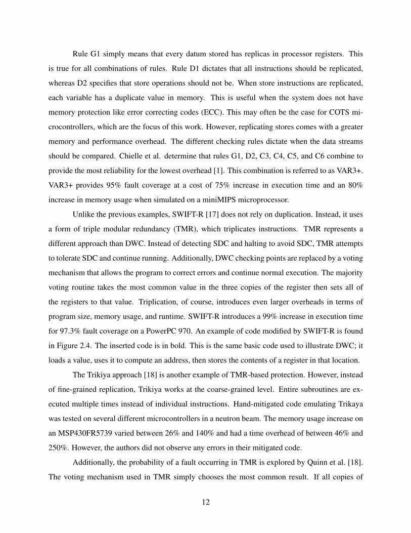
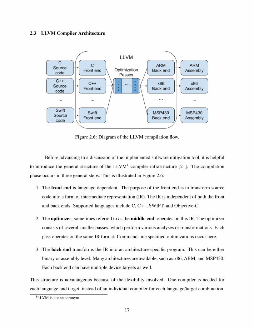
Before advancing to a discussion of the implemented software mitigation tool, it is helpful
to introduce the general structure of the LLVM1 compiler infrastructure [21]. The compilation
phase occurs in three general steps. This is illustrated in Figure 2.6.
1. The front end is language dependent. The purpose of the front end is to transform source
code into a form of intermediate representation (IR). The IR is independent of both the front
and back ends. Supported languages include C, C++, SWIFT, and Objective-C.
2. The optimizer, sometimes referred to as the middle end, operates on this IR. The optimizer
consists of several smaller passes, which perform various analyses or transformations. Each
pass operates on the same IR format. Command-line specified optimizations occur here.
3. The back end transforms the IR into an architecture-specific program. This can be either
binary or assembly level. Many architectures are available, such as x86, ARM, and MSP430.
Each back end can have multiple device targets as well.
This structure is advantageous because of the flexibility involved. One compiler is needed for
each language and target, instead of an individual compiler for each language/target combination.1LLVM is not an acronym
17

LLVM is also convenient because the IR is human readable, similar to assembly language [30]. Ad-
ditionally, there are many different front and back ends available. As of the date of this publication,
LLVM has 11 front ends and 30 back ends, allowing for a total of 330 different language/archi-
tecture pairings with one tool suite [31]. There are also multitudinous transformation, utility, and
analysis passes available.
2.4 Chapter Summary
This chapter has introduced different software-based fault mitigation schemes. These pro-
tect the control flow and data flow of the program. One of the main forms of data flow protection is
replication and comparison of program instructions. Control flow mitigation has many variations,
but several focus on inserting signatures inside of each basic block to ensure that the program flow
takes valid transitions. In the next chapter we discuss how we automatically apply some of these
techniques to software in compilation.
18

CHAPTER 3. COAST: COMPILER-ASSISTED SOFTWARE FAULT TOLERANCE
In order to mitigate the effects of radiation-induced upsets in microcontroller software, we
have explored several forms of software mitigation as described in Chapter 2. However, applying
these techniques by hand would be time consuming and difficult. Instead, we decided to investi-
gate automated protection using compiler passes. In pursuit of this goal we developed an automated
tool, COAST (COmpiler-Assisted Software fault Tolerance), which is built as a compiler pass in
the LLVM compiler infrastructure. It is highly customizable and applies several forms of software
fault tolerance. This chapter discusses the different fault mitigation schemes we surveyed. Addi-
tionally, we discovered a number of challenges that must be addressed when automating software
protection. These challenges, as well as the associated solutions, are also presented. All of these
techniques are implemented in software and tested to ensure the effectiveness.
3.1 Basic COAST Protections
We chose three common, well tested, relatively simple approaches as a starting point to
our exploration of automated protection. This allowed us to compare our results to previous work.
First, for data flow protection, we tested duplicate with compare (DWC), as implemented by Oh
et al. [11] and Quinn et al. [18]. Additionally, in the interest of correcting errors during runtime,
we also implemented triple modular redundancy (TMR) after Chang et al. [17]. This thesis will
refer to DWC and TMR together as replication. Finally, we implemented CFCSS [24] as a form
of control flow protection. This has been well studied by Shrivastava et al. [5] and Zhu et al. [32].
Although there is some doubt about the effectiveness of CFCSS, it is one of the earliest forms
of control flow checking and provides a good basis for developing other forms of control flow
protection. In summary, the tested techniques are:
• Duplicate with compare (data flow protection)
• Triple modular redundancy (data flow protection)
19

• CFCSS (control flow protection)
These techniques have different fault approaches and overheads. Care should be taken to choose
the appropriate forms of protection for specific applications. Pseudocode listings illustrating each
form of mitigation are included in the next sections. The pseudocode is loosely based on LLVM
IR but edited for clarity.
3.1.1 Overview
We determined that, for data flow protection, a similar approach could be used for both du-
plication and triplication of instructions. The goal of the data flow protection LLVM optimization
pass is to perform redundant computations to increase reliability. The pass replicates instructions
and makes the replicas dependent so that multiple copies of the program can be run together. Ad-
ditionally, the copies of the program are synchronized periodically to detect errors.
The pass begins by first finding all functions that should be protected. It then iterates
through every IR instruction in these functions, detecting what instructions to clone and adding
them to a list. Once this list is complete then COAST replicates every instruction in the list.
Additionally, dependencies between instructions are updated so each clone operates on its own
data. The function signatures are also modified to include the clones of the original arguments.
When all of the clones have been inserted into the code, the pass sweeps through the program and
detects where synchronization logic should be placed. It then inserts comparison statements and
error handlers for DWC, or voter code for TMR.
The goal of the CFCSS pass is to calculate and place signatures for each basic block, insert
comparison logic, and create an error handler. It first iterates over all basic blocks, generating and
inserting a random signature for each block, as well as the loading and exclusive-or instructions. It
then iterates over all basic blocks to see if its successors have the appropriate signature. If they did
not, we faced the fan in problem discussed in Section 2.2.2. We solved this by inserting another
basic block between the two. This basic block acts as a buffer that updates the appropriate signature
adjuster register.
20

3.1.2 Duplicate with Compare
The first form of data flow protection is DWC. Figure 3.1 shows a code snippet before and
after DWC was applied. The original code is on the left and the modified code is on the right. The
bold text indicates changes made by our pass. In this example the base code is a conditional branch
depending on if a variable from memory is equal to one. Specifically, the program fetches a value
from memory into register r0, subtracts one and stores it in r1. It then compares r1 to 0 and stores
the result in register r2, then branches depending on the comparison.
do :l d r0 = i
r1 = sub r0 , 1
r2 = cmp r1 , 0
b r neq r2 do
(a) Original code
do :l d r0 = ild r10 = i copyr1 = sub r0 , 1r11 = sub r10, 1r2 = cmp r1 , 0r12 = cmp r11, 0*r5 = cmp r2, r12*br neq r5 faultDetectedbr neq r2 do
(b) DWC code
Figure 3.1: DWC-based fault detection code.
The duplicated instructions perform the same operations as the original instructions, but
operate on duplicated data. Here, the program loads i into r0, then loads the copy of i, i copy,
into r10. Both r0 and r10 are decremented and stored, then the results of the subtraction are both
compared to zero. The comparison between i-1 and 0 is in r2, while the comparison between
i copy-1 and 0 is stored in r12.
In order to detect errors, the different copies of data are periodically checked against each
other to check for differences. The places where these checks are performed are referred to as
synchronization points. These are inserted at several points throughout the program, as explained
in Section 2.2.1. Branches are one such synchronization point, so comparison instructions are
inserted there. These are marked by asterisks. In order to ensure that the branch condition executes
correctly, r2 and r12 are compared and the results are saved to r5. If r5 indicates that r2 and r12 are
21

different, then control is passed to an error handler, faultDetected. This function is automatically
added and simply calls abort(), although this can be overridden. If the registers are identical,
program execution continues normally.
EDDI [11], another DWC approach explained in Section 2.2.1, has one main difference
when compared to our code, as shown in Figure 3.1. EDDI stores all duplicated values a constant
offset away from the original value in memory. In the optimization stage where COAST runs,
however, the IR has no concept of a memory space. As a result, DWC cannot determine the
distance between i and i copy. Consequently, it cannot compare the offset of the addresses, which
eliminates potential synchronization points. This should not have a significant penalty on mean
work to failure, as explored by Chielle et al. [33].
Additionally, the overhead associated with DWC is lower than appears in this example.
Figure 3.1 only shows three instructions that execute before a synchronization point is reached,
which adds in two more instructions of overhead. In practice, however, the regions of code between
synchronization points are much longer.
3.1.3 Triple Modular Redundancy
TMR replication is similar in structure to DWC. However, the synchronization logic is
different. DWC compares two results and branches if they are not equal. TMR must perform
a majority vote to find the correct value then propagate that value throughout the program. This
requires more overhead than DWC. Figure 3.2 contains an example of source code before and after
the TMR pass has been run.
As before, the base code loads a value from memory, subtracts one from it, compares the
results to zero, and does a conditional branch based on the result. In this example each step is
stored in a different register. In the TMR version each computation instruction is repeated twice
more, storing the result in unique registers each time. The branch instruction is a synchronization
point, so the starred voting logic is placed here. The code must perform a majority vote of r2,
r12, and r22 and use that value for the branch. The main difference between this implementation
and previous work that implemented TMR, SWIFT-R [17], is the voting routine. SWIFT-R calls
a majority voting routine, whereas COAST implements the voting logic inline. We needed the
voting code to be efficient and not add additional control flow operations, so we settled on an
22

implementation that uses a ternary select operation. The insertion of the voters occurs in three
steps:
1. First, two values are compared. In this example registers r2 and r12 are checked and the
result is stored in r3.
2. The select instruction is used to determine what value should be used. The syntax is similar
to the ternary operator in C. If r3 is true, then the value of r2 is stored in r4. If not, then r2
and r12 must be different, so r22 is assumed to be correct and the value is copied to r4.
3. The instruction that used the original value is modified. In this case, the branch instruction
is altered to use the result of the select instruction, r4, instead of r2.
do :l d r0 = i
r1 = sub r0 , 1
r2 = cmp r1 , 0
b r neq r2 do
(a) Original code
do :l d r0 = ild r10 = i copyld r20 = i copy2r1 = sub r0 , 1r11 = sub r10, 1r21 = sub r20, 1r2 = cmp r1 , 0r12 = cmp r11, 0r22 = cmp r21, 0*r3 = cmp r2, r12*r4 = select r3, r2, r22*br neq r4 do
(b) TMR code
Figure 3.2: TMR based fault correction code.
COAST, like other tools [4], [16], assumes a fault model of only single bit upsets at a time
and therefore cannot correct multiple errors in the same set of variables. This scenario, when the
voter cannot determine the correct value, is referred to as TMR failure. The probability of this oc-
curring was determined by Quinn et al. [18] and is shown in Equation 2.1. The equation represents
the probability that a single variable will be corrupted twice. However, a synchronization point
can rely on more than one variable. For example, consider a branch instruction that depends on the
23
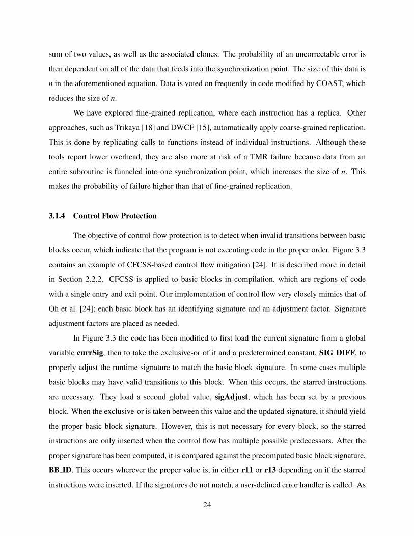
sum of two values, as well as the associated clones. The probability of an uncorrectable error is
then dependent on all of the data that feeds into the synchronization point. The size of this data is
n in the aforementioned equation. Data is voted on frequently in code modified by COAST, which
reduces the size of n.
We have explored fine-grained replication, where each instruction has a replica. Other
approaches, such as Trikaya [18] and DWCF [15], automatically apply coarse-grained replication.
This is done by replicating calls to functions instead of individual instructions. Although these
tools report lower overhead, they are also more at risk of a TMR failure because data from an
entire subroutine is funneled into one synchronization point, which increases the size of n. This
makes the probability of failure higher than that of fine-grained replication.
3.1.4 Control Flow Protection
The objective of control flow protection is to detect when invalid transitions between basic
blocks occur, which indicate that the program is not executing code in the proper order. Figure 3.3
contains an example of CFCSS-based control flow mitigation [24]. It is described more in detail
in Section 2.2.2. CFCSS is applied to basic blocks in compilation, which are regions of code
with a single entry and exit point. Our implementation of control flow very closely mimics that of
Oh et al. [24]; each basic block has an identifying signature and an adjustment factor. Signature
adjustment factors are placed as needed.
In Figure 3.3 the code has been modified to first load the current signature from a global
variable currSig, then to take the exclusive-or of it and a predetermined constant, SIG DIFF, to
properly adjust the runtime signature to match the basic block signature. In some cases multiple
basic blocks may have valid transitions to this block. When this occurs, the starred instructions
are necessary. They load a second global value, sigAdjust, which has been set by a previous
block. When the exclusive-or is taken between this value and the updated signature, it should yield
the proper basic block signature. However, this is not necessary for every block, so the starred
instructions are only inserted when the control flow has multiple possible predecessors. After the
proper signature has been computed, it is compared against the precomputed basic block signature,
BB ID. This occurs wherever the proper value is, in either r11 or r13 depending on if the starred
instructions were inserted. If the signatures do not match, a user-defined error handler is called. As
24

the basic block branches to another location, the global signature and signature adjuster registers
are updated.
do :l d r0 = ir1 = sub r0 , 1r2 = cmp r1 , 0
b r neq r2 do
(a) Original code
do :ld r10 = currSigr11 = xor r10, SIG DIFF*ld r12 = sigAdjust*r13 = xor r11, r12r14 = cmp r11/r13, BB IDbr neq r14 errorHandler
do . c o n t :l d r0 = ir1 = sub r0 , 1r2 = cmp r1 , 0store currSig = BB IDstore sigAdjust = BB ADJUSTERbr neq r2 do
(b) CFCSS code
Figure 3.3: CFCSS-based fault detection code.
Due to the small size of the basic block provided in Figure 3.3, the overhead needed for
CFCSS appears larger than what occurs in practice with larger basic blocks. Additionally, interrupt
service routines (ISRs) are a special case when using CFCSS. If an ISR is called in the middle of
a basic block then it will alter the global runtime signature, causing the code to fail at the next
transition. This is fixed by not applying CFCSS to ISRs.
3.2 Configuration Options
Because our approach is fully automated we can explore multiple replication styles. This is
helpful in the analysis of previous work. We would also like this tool to be useful to others, so we
have aimed to make COAST flexible and customizable. This includes supporting different code
styles, allowing the user to alter the frequency of synchronization, and providing several techniques
to allow the user to examine the trade off between overhead and protection. This section describes
25

Table 3.1: Rules for data flow protection [1].
Global Rules(Valid for all techniques)
G1 Each register has a replica
Replication Rules(Performing same operation on register’s replica)
D1 All instructionsD2 All instructions, except stores
Checking Rules(Comparing a register with its replica)
C1 Before each read on the register(excluding load/store and branch/jump instructions)
C2 After each write on the registerC3 The register that contains the address before loadsC4 The register that contains the datum before storesC5 The register that contains the address before storesC6 Before branches or jumps
the different protection schemes available to the user in our implementation. Chapter 4 contains
results from fault injection, which show the efficacy of these different options.
As outlined in Section 2.2.1 there are several rules that are popular to use for data flow
protection. They dictate the scope of replication and the location of synchronization points. The
set of rules is reproduced in Table 3.1 for convenience. We have used these rules for consistency
with previous work. We have incorporated these rules, among others, into DWC and TMR. Table
3.2 contains the corresponding COAST command line options that can be used to control COAST,
including the options to enable or disable these different rules. Each option is explained in more
detail in the following subsections. Additionally, there are equivalent in-line code directives that
can be used instead of the command line flags for ease of use. More information on these directives
is available with the COAST documentation.
26

Table 3.2: Pass command line configuration options.
Command line option Effect-noMemReplication Don’t replicate variables in memory (ie. use rule D2 instead of
D1).-noLoadSync Don’t synchronize on data loads (C3).
-noStoreDataSync Don’t synchronize the data on data stores (C4).-noStoreAddrSync Don’t synchronize the address on data stores (C5).-ignoreFns=<X> <X> is a comma separated list of the functions that should not
be replicated.-ignoreGlbls=<X> <X> is a comma separated list of the global variables that
should not be replicated.-skipLibCalls=<X> <X> is a comma separated list of library functions that should
only be called once.-replicateFnCalls=<X> <X> is a comma separated list of user functions where the body
of the function should not be modified, but the call should bereplicated instead.
-countErrors Enable TMR to track the number of errors corrected.-runtimeInitGlbls=<X> <X> is a comma separated list of the replicated global variables
that should be initialized at runtime.-i or -s Interleave (-i) the instruction replicas with the original instruc-
tions (as in Figure 3.2), or group them together and place themimmediately before the synchronization logic (-s). COAST de-faults to -s.
3.2.1 Replication Rules
VAR3+, the set of replication rules introduced by Chielle et al. [1], instructs that all registers
and instructions, except store instructions, should be duplicated. The data used in branches, the
addresses before stores and jumps, and the data used in stores are all synchronized and checked
against their duplicates. As shown in Table 3.1 this corresponds to rules G1, D2, C3, C4, C5, and
C6. VAR3+ claims to catch 95% of data errors [22], [23], so we used it as a starting point for
automated mitigation. However, we removed rule D2, which does not replicate store instructions,
in favor of D1, which does. This results in replication of all variables in memory, and is desirable as
microcontrollers have no guarantee of protected memory. The synchronization rules are included
in both DWC and TMR protection. Rules C1 and C2, synchronizing before each read and write on
the register, respectively, are not included in our pass because these were shown in [1] to provide an
excessive amount of synchronization. G1, replicating all registers, and C6, synchronizing before
27
branch or store instructions, cannot be disabled as these are necessary for the protection to function
properly. The command line options outlined in Table 3.2 disable some of the remaining rules.
The first option, -noMemReplication, should be used whenever memory has a separate
form of protection, such as error correcting codes (ECC). The option specifies that neither store
instructions nor variables should be replicated. This can dramatically speed up the program be-
cause there are fewer memory accesses. Loads are still executed repeatedly from the same address
to ensure no corruption occurs while processing the data.
The option -noStoreAddrSync corresponds to C5. In previous work [11] memory was
simply duplicated and each duplicate was offset from the original value by a constant. However,
COAST runs before the linker, and thus has no notion of an address space. We implement rules C3
and C5, checking addresses before stores and loads, for data structures such as arrays and structs
that have an offset from a base address. These offsets, instead of the base addresses, are compared
in the synchronization logic.
3.2.2 Replication Scope
The sphere of replication (SoR) [34] is a concept detailing what portions of code are pro-
tected. Although including the entire program in the SoR should maximize the fault coverage, the
overhead can be prohibitively high. As Quinn et al. [7] show, it is possible to use coarse-grained
replication to keep a high level of fault tolerance while reducing overhead. To that end, COAST
allows users to explicitly control how functions and global variables should be replicated.
The user can specify any functions and global variables that should not be protected us-
ing -ignoreFns and -ignoreGlbls. At minimum, these options should be used to exclude
code that interacts with hardware devices (GPIO, UART) from the SoR. Replicating this code
is likely to lead to errors. The option -replicateFnCalls causes user functions to be called in
a coarse grained way, meaning the call is replicated instead of fine-grained instruction replication
within the function body. Library function calls can also be excluded from replication via the flag
-skipLibCalls, which causes those calls to only be executed once. These two options should be
used when multiple independent copies of a return value should be generated, instead of a single
return value propagating through all replicated instructions. Section 3.3.1 contains a more detailed
description of some challenges that can arise from manually changing the SoR.
28
3.2.3 Error Logging
This option was developed for tests in a radiation beam, where upsets are stochastically
distributed, unlike fault injection tests where one upset is guaranteed for each run. COAST can be
instructed to keep track of the number of corrected faults via the flag -countErrors. This flag
allows the program to detect corrected upsets, which yields more precise results on the number of
radiation-induced SEUs. This option is only applicable to TMR because DWC halts on the first
error. A global variable, TMR ERROR CNT, is incremented each time that all three copies of
the datum do not agree. If this global is not present in the source code then the pass creates it.
The user can print this value at the end of program execution, or read it using a debugging tool.
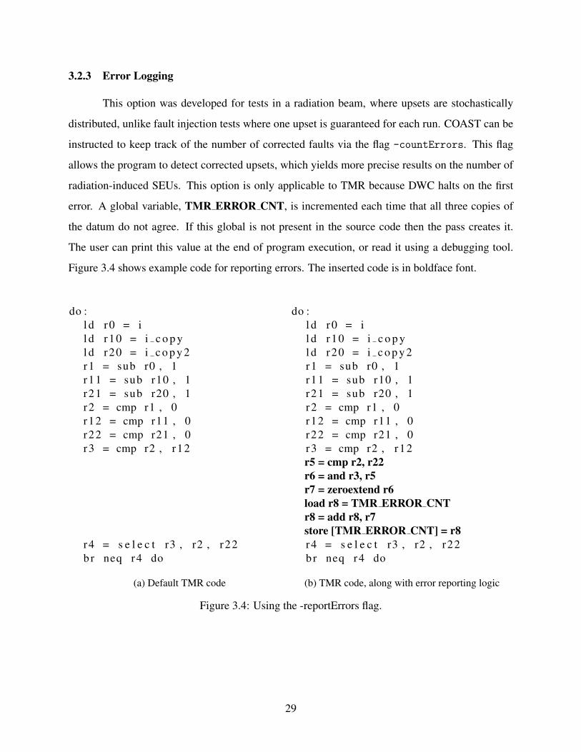
Figure 3.4 shows example code for reporting errors. The inserted code is in boldface font.
do :l d r0 = il d r10 = i c o p yl d r20 = i c o p y 2r1 = sub r0 , 1r11 = sub r10 , 1r21 = sub r20 , 1r2 = cmp r1 , 0r12 = cmp r11 , 0r22 = cmp r21 , 0r3 = cmp r2 , r12
r4 = s e l e c t r3 , r2 , r22b r neq r4 do
(a) Default TMR code
do :l d r0 = il d r10 = i c o p yl d r20 = i c o p y 2r1 = sub r0 , 1r11 = sub r10 , 1r21 = sub r20 , 1r2 = cmp r1 , 0r12 = cmp r11 , 0r22 = cmp r21 , 0r3 = cmp r2 , r12r5 = cmp r2, r22r6 = and r3, r5r7 = zeroextend r6load r8 = TMR ERROR CNTr8 = add r8, r7store [TMR ERROR CNT] = r8r4 = s e l e c t r3 , r2 , r22b r neq r4 do
(b) TMR code, along with error reporting logic
Figure 3.4: Using the -reportErrors flag.
29
3.2.4 Input Initialization
Global variables with initial values provide an interesting problem for testing. By default,
these initial values are assigned to each replicate at compile time. This models the scenario where
the SoR expands into the source of the data. However, this does not accurately model the case
when code inputs need to be replicated at runtime. This could happen, for instance, if a UART was
feeding data into a program and storing the result in a global variable. When global variables are
listed using -runtimeInitGlbls the pass inserts memcpy calls to copy global variable data into
the replicates at runtime. This supports scalar values as well as aggregate data types, such as arrays
and structures.
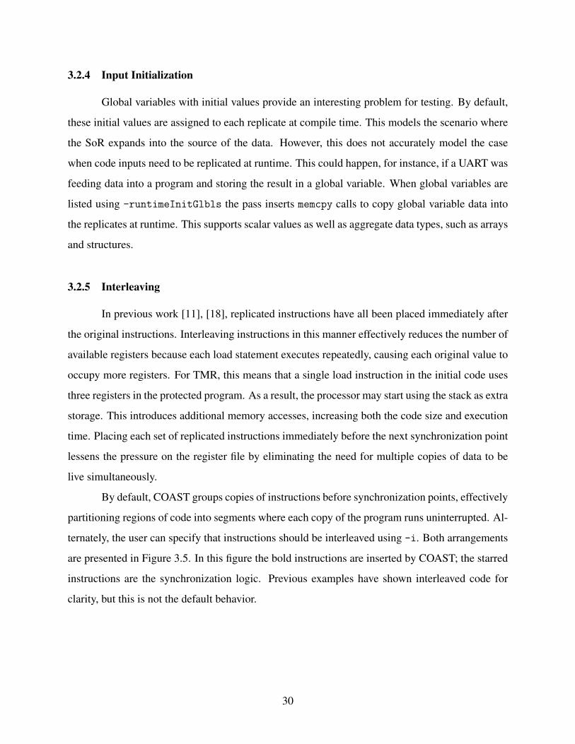
3.2.5 Interleaving
In previous work [11], [18], replicated instructions have all been placed immediately after
the original instructions. Interleaving instructions in this manner effectively reduces the number of
available registers because each load statement executes repeatedly, causing each original value to
occupy more registers. For TMR, this means that a single load instruction in the initial code uses
three registers in the protected program. As a result, the processor may start using the stack as extra
storage. This introduces additional memory accesses, increasing both the code size and execution
time. Placing each set of replicated instructions immediately before the next synchronization point
lessens the pressure on the register file by eliminating the need for multiple copies of data to be
live simultaneously.
By default, COAST groups copies of instructions before synchronization points, effectively
partitioning regions of code into segments where each copy of the program runs uninterrupted. Al-
ternately, the user can specify that instructions should be interleaved using -i. Both arrangements
are presented in Figure 3.5. In this figure the bold instructions are inserted by COAST; the starred
instructions are the synchronization logic. Previous examples have shown interleaved code for
clarity, but this is not the default behavior.
30
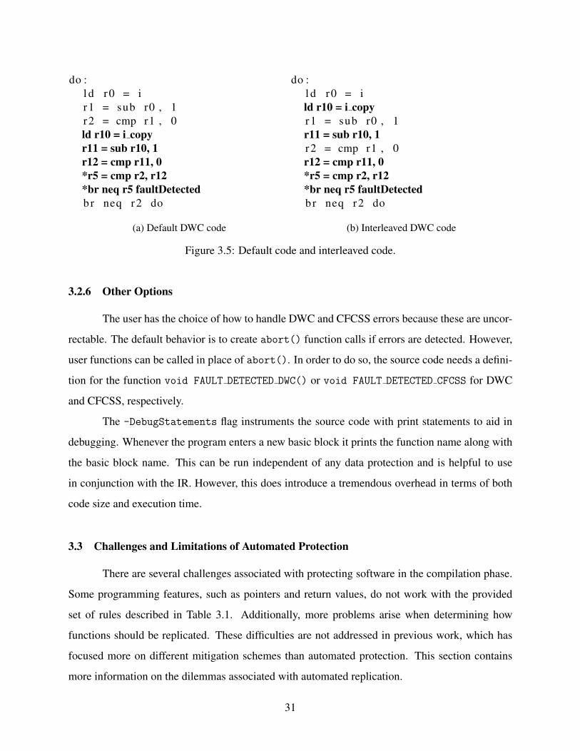
do :l d r0 = ir1 = sub r0 , 1r2 = cmp r1 , 0ld r10 = i copyr11 = sub r10, 1r12 = cmp r11, 0*r5 = cmp r2, r12*br neq r5 faultDetectedbr neq r2 do
(a) Default DWC code
do :l d r0 = ild r10 = i copyr1 = sub r0 , 1r11 = sub r10, 1r2 = cmp r1 , 0r12 = cmp r11, 0*r5 = cmp r2, r12*br neq r5 faultDetectedbr neq r2 do
(b) Interleaved DWC code
Figure 3.5: Default code and interleaved code.
3.2.6 Other Options
The user has the choice of how to handle DWC and CFCSS errors because these are uncor-
rectable. The default behavior is to create abort() function calls if errors are detected. However,
user functions can be called in place of abort(). In order to do so, the source code needs a defini-
tion for the function void FAULT DETECTED DWC() or void FAULT DETECTED CFCSS for DWC
and CFCSS, respectively.
The -DebugStatements flag instruments the source code with print statements to aid in
debugging. Whenever the program enters a new basic block it prints the function name along with
the basic block name. This can be run independent of any data protection and is helpful to use
in conjunction with the IR. However, this does introduce a tremendous overhead in terms of both
code size and execution time.
3.3 Challenges and Limitations of Automated Protection
There are several challenges associated with protecting software in the compilation phase.
Some programming features, such as pointers and return values, do not work with the provided
set of rules described in Table 3.1. Additionally, more problems arise when determining how
functions should be replicated. These difficulties are not addressed in previous work, which has
focused more on different mitigation schemes than automated protection. This section contains
more information on the dilemmas associated with automated replication.
31

3.3.1 Challenges
The majority of the complications associated with automated, fine-grained replication in-
volve function calls. Calling protected functions from other protected functions requires special
care. Function calls that cross SoR boundaries also present problems. This occurs when some
functions are protected and some are not, such as interrupt service routines, user code that refer-
ences hardware, or user code that is intentionally not mitigated in order to reduce overhead. Figures
3.6 and 3.7 illustrate these difficulties. These figures show a series of functions, A, B, and C, in an
example program. Arrows denote one function calling another. A tick mark indicates that the user
has indicated the function should be protected, causing all of the instructions within the function
to be replicated. The image on the left of each subfigure shows program flow before protection
is applied, and the image on the right shows the program flow after mitigation has been applied.
Protection is applied to function A in all cases.
(a) Calling a protected function (b) Calling a shared function
Figure 3.6: Calling protected functions from other functions.
One of the first problems to consider is how to call protected functions from other protected
functions. Consider Figure 3.6a, where A and B are both protected. Function A′ has multiple
copies of the data that should be provided as arguments for B. We are interested in fine-grained
replication, where every copy of the instructions inside B′ relies on the copies calculated in A′,
so we modify the function signature for B. B′ has a new function signature that contains both the
original parameters and the extra parameters to allow A′ to pass all of the replicated data. All of
the calls to B are changed to B′. This allows functions to call other functions without crossing
the SoR. By default COAST performs this transformation on all user functions called by protected
functions.
32

Additionally, shared function calls present an obstacle. In Figure 3.6b function A is pro-
tected, so function C will be protected and have its call signature modified to include all the extra
arguments for the replicated data. However, if B is not protected and calls C, it will need the
original function signature for C. A solution is to create two separate functions for C. We leave
an unchanged copy of C that B is free to call, while creating a protected version, C′, for A′. This
preserves proper program behavior and maintains the SoR at the cost of increased program size.
(a) Triplicating the function call (b) A single function call
Figure 3.7: Calling unprotected functions from protected functions.
Another problem is determining how to call unprotected functions within protected func-
tions, crossing the SoR. In Figure 3.7 assume that the user has requested that A be included in
the sphere of replication, but B should not. There are two options on how to handle the replicated
call. The first, as shown in Figure 3.7a, is to replicate the function call in the body of function
A′. Although the figure shows three calls, indicating TMR is being used, this is equally valid for
DWC. In each of the different calls A′ will provide a different copy of its data as the function argu-
ments. However, if B has side effects on a global scale, such as incrementing a counter or printing
a message, this can cause incorrect program execution. Automated protection is not permitted to
cause the program to operate differently, so the call cannot always be made repeatedly.
Library calls are a special case of function calls that cross the SoR. In order to have pro-
tected library code, one would have to recompile the libraries from the source code. There are two
approaches to remedy this situation without recompiling each library. First, as above, the call can
be replicated two or three times. This is necessary in cases where copies of data should not be
identical, such as when calling the C library function malloc(), which returns a pointer to allo-
cated memory. If each copy of the variable did not have its own allocated space, all replicas would
operate on the same memory location, potentially causing errors. For certain library functions,
33

however, this approach can cause incorrect program execution. Consider the case when a call to
rand() would be called repeatedly for each set of replicated instructions, causing each set to op-
erate on different data. A second solution is to pass over the call without replicating it; a user most
likely does not want to call printf() multiple times. This is illustrated in Figure 3.7b, assuming
B is a library call. In this case the arguments to the function call are synchronized before being
passed into the library call. The default behavior is to clone all library calls. The user can specify
any exceptions, such as printf(), using the -skipLibCalls flag.
Another difficulty with automated protection is that protected user functions only return a
single value. This can cause a problem if the value returned is not meant to be operated on multiple
times. As an example, consider a user function that takes in several variables, packages them into
a new object, then returns a pointer to the newly created object. The LLVM IR does not support
multiple return values from a single function, so that single pointer is then distributed among all the
program replicas. If the object is deleted later in a protected function, then free() would be called
multiple times on the same pointer, resulting in a program crash. The flag -replicateFnCalls
exists to avoid this scenario. When passed in functions through this option, COAST avoids modi-
fying the original function, opting instead to call it repeatedly. This option should always be used
when the return value of a function should not be shared between the replicated instructions.
Table 3.3 summarizes the different approaches that can be taken to solve the challenges pre-
sented in this section, as well as the corresponding command line options and example scenarios.
These solutions have been developed as we have encountered incorrect execution, and represent
the first effort at addressing these types of errors that arise due to automatic fine-grained mitigation.
In this table <X> designates a comma separated list of names.
3.3.2 Limitations
A current limitation of the pass is that function return values are not replicated. Instead,
a single value is returned, then passed into the instruction replicas. This introduces a single point
of failure, where an upset in one place can cause an error in the system. This could be modified
in future work by modifying the function signature to include pointers that could serve as return
values for each copy of instructions. Each function would then update the referenced memory
location at the end of the function, instead of returning a single value.
34

Table 3.3: Potential solutions to challenges with automated replication.
Desired Behavior Function Type Option Use Case
Protectcalled function
(Fig. 3.6a)
User DefaultStandard behavior, use formost cases.
Library N/ACannot modify library calls.Instead, see the case below.
Replicate call(Fig. 3.7a)
User -replicateFnCalls=<X>
When the return value needsto be unique to each instruc-tion replica, e.g. pointers.
Library DefaultBy default the library callsare performed repeatedly.Use for most calls.
Call once,unmodified(Fig. 3.7b)
User -ignoreFns=<X>
Interrupt service routinesand synchronization logic,such as polling on an exter-nal pin.
Library -skipLibCalls=<X>
Whenever the call shouldnot be repeated, such as callsinterfacing with I/O.
Additionally, certain library calls are not supported. For instance, the C library function
fscanf() cannot be protected. This call reads from a file and stores the data in a variable, which
it accesses via a pointer passed by argument. This function does not return a value, so instruction
copies never get the proper data. Calling the function repeatedly would require either multiple
copies of the same input file or redundant data in the file. Neither of these options are acceptable for
automatic protection. We have decided to forgo support for fscanf() and similar file processing
calls, assuming that an embedded microcontroller would not be interfacing with an external file
system. Future work can explore methods of protecting these calls.
Multiple levels of indirection via pointer can cause program problems upon synchroniza-
tion. If a variable contains a pointer to a pointer, according to rule C4 the data residing in registers
should be equal and checked. Each program copy, however, should have a unique pointer. Check-
ing the equality of these pointers will cause the synchronization to fail. An example of this can
be seen in Figure 3.8. In this case the variables data and data copy can share the same value and
be synchronized. However, ptr and ptr copy contain different values, causing a synchronization
35

failure. It is possible to dereference the pointer to get to data, but the values ptrToPtr and ptr-
ToPtr copy would cause this strategy to fail. This can get more complicated when structs or arrays,
which are treated like pointers, are considered instead of integer data types. We conservatively dis-
able synchronization on all pointer data types to prevent failures, which could theoretically reduce
the fault coverage of the pass by reducing the amount of data that is checked. This is a shortcoming
of mitigation in the compilation step. We rely on the results presented by Chielle et al. [1] that this
will not incur too large a penalty on reliability.
i n t d a t a ;i n t d a t a c o p y ;i n t * p t r = &d a t a ;i n t * p t r c o p y = &d a t a c o p y ;i n t ** p t r T o P t r = &p t r ;i n t ** p t r T o P t r c o p y = &p t r c o p y ;
Figure 3.8: Example of code with double indirection.
3.4 Validation
It is crucial that, while modifying code, COAST preserves correct program functionality.
Additionally, COAST needs to correctly process all forms of LLVM IR. In order to achieve these
goals COAST has been tested using a variety of benchmarks. These programs are self-checking,
which means they compare the result of the calculations to a known golden value to ensure correct
operations. The programs are compiled and tested with all of the different COAST options both
individually and in some combinations, such as CFCSS and DWC together. The benchmarks used
are:
• A number of custom programs, including a matrix multiply, quicksort, CRC checksum,
cache test, and AES encryption. These were modified versions of the code found at [35].
• The CHStone benchmarks for high-level synthesis [36].
• The CoreMark benchmark suite for embedded systems [37].
36

• The MiBench commercially-representative benchmarks for embedded systems [38].
• A self-checking series of fast Fourier transforms (FFT) [39].
• The llvm-stress tool, an LLVM command which generates random IR. Although the gener-
ated code cannot be run, it does ensure that COAST modifies the IR in a legal manner.
All of these programs are run on our local PC using the lli program, which is a runtime interpreter
for LLVM IR. This ensures that COAST preserves program functionality. Testing for increased
fault tolerance is done via fault injection, which is discussed in Chapter 4.
3.5 Running COAST
In Section 2.3 the basic compiler structure was introduced. COAST operates during the
optimization phase of the LLVM optimizer. It is compiled and loaded into the LLVM optimizer,
which operates on the IR of the program. Makefiles are used to properly load the COAST modules
and compile the source code. Special care has been taken to ensure that no optimizations occur
after COAST runs, as this has been known to remove replicated instructions. Options are simply
passed in the command line of the LLVM optimizer. The different protection schemes available,
along with the associated COAST command line options, are shown in Table 3.4.
Table 3.4: COAST protections.
Effect Command Line Option
Duplicate With Compare (data flow protection) -DWC
Triple Modular Redundancy (data flow protection) -TMR
CFCSS (control flow protection) -CFCSS
The commands used to compile code using COAST are listed in Figure 3.9. First, Clang,
a front end for C and C++, is used to transform the source code into LLVM IR. When passed the
-emit-llvm flag it generates a file in LLVM byte code (.bc), a binary version of the IR. Next, the
optimizer is run. The possible options are described in this chapter. Finally, the back end, llc, is
used to generate an assembly file. If the user would like to look through the IR before or after the
37
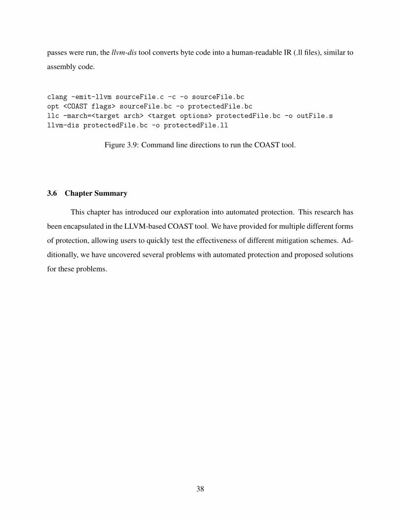
passes were run, the llvm-dis tool converts byte code into a human-readable IR (.ll files), similar to
assembly code.
clang -emit-llvm sourceFile.c -c -o sourceFile.bc
opt <COAST flags> sourceFile.bc -o protectedFile.bc
llc -march=<target arch> <target options> protectedFile.bc -o outFile.s
llvm-dis protectedFile.bc -o protectedFile.ll
Figure 3.9: Command line directions to run the COAST tool.
3.6 Chapter Summary
This chapter has introduced our exploration into automated protection. This research has
been encapsulated in the LLVM-based COAST tool. We have provided for multiple different forms
of protection, allowing users to quickly test the effectiveness of different mitigation schemes. Ad-
ditionally, we have uncovered several problems with automated protection and proposed solutions
for these problems.
38

CHAPTER 4. FAULT INJECTION TESTING
This chapter describes our methodology and experiments to simulate SEUs to test COAST
before a full scale radiation test. Fault injection is typically used to test the effectiveness of SEU
mitigation due to the high cost of radiation testing [40]–[42]. Additionally, the effect of each fault
can be traced and the results characterized, allowing for a better understanding of the impacts of
faults on the system.
4.1 Approach
There are two main approaches to fault injection as described by Quinn et al. [40]. The
first is fault simulation, which use a simulator to reproduce the behavior of a full processor. As
the simulation proceeds, faults are introduced to the processor [13], [23], [28]. These techniques
are useful because they can track how faults propagate through the system. Additionally, they can
alter the state at any point in the processor, allowing for more thorough testing. However, this does
require an advanced simulator.
The second method of fault injection is fault emulation, which runs on hardware instead of
simulation. For instance, a program can be deployed on the device under test (DUT) with another
processor acting as a monitor and fault injector [16], [29], [41]. Alternately, one can generate
machine code and introduce an error into the final binary, then run the program locally [11], [17].
This is much easier to develop, but provides less information on the characteristics of the DUT.
Additionally, it can be much faster to run a program on hardware than in simulation.
We have implemented a fault emulation technique to test COAST because no fault injection
tool was available for our DUT, the MSP430. Specifically, we run the produced binary on a devel-
opment board, then inject faults from the host machine. This will allow us to obtain many results
quickly. Additionally, the focus of this work lies on different forms of automated protection, so we
chose an easy-to-implement fault injection approach.
39
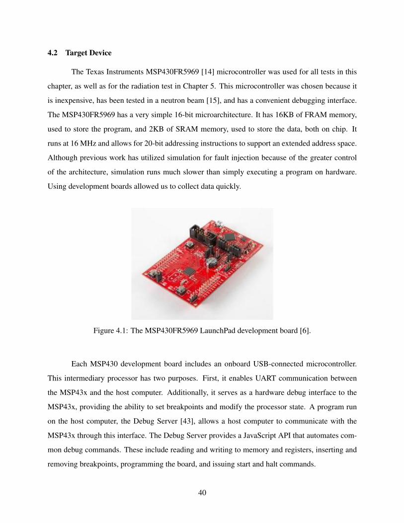
4.2 Target Device
The Texas Instruments MSP430FR5969 [14] microcontroller was used for all tests in this
chapter, as well as for the radiation test in Chapter 5. This microcontroller was chosen because it
is inexpensive, has been tested in a neutron beam [15], and has a convenient debugging interface.
The MSP430FR5969 has a very simple 16-bit microarchitecture. It has 16KB of FRAM memory,
used to store the program, and 2KB of SRAM memory, used to store the data, both on chip. It
runs at 16 MHz and allows for 20-bit addressing instructions to support an extended address space.
Although previous work has utilized simulation for fault injection because of the greater control
of the architecture, simulation runs much slower than simply executing a program on hardware.
Using development boards allowed us to collect data quickly.
Figure 4.1: The MSP430FR5969 LaunchPad development board [6].
Each MSP430 development board includes an onboard USB-connected microcontroller.
This intermediary processor has two purposes. First, it enables UART communication between
the MSP43x and the host computer. Additionally, it serves as a hardware debug interface to the
MSP43x, providing the ability to set breakpoints and modify the processor state. A program run
on the host computer, the Debug Server [43], allows a host computer to communicate with the
MSP43x through this interface. The Debug Server provides a JavaScript API that automates com-
mon debug commands. These include reading and writing to memory and registers, inserting and
removing breakpoints, programming the board, and issuing start and halt commands.
40
4.3 Fault Injection Framework
We have developed the Fault Injection JavaScript Infrastructure (FIJI) as our fault injection
tool. This is a set of scripts that provides automated, reliable, rapid fault injection. It supports all
Texas Instruments development boards that have on-board debugging units, and has been tested on
both MSP430 and ARM-based MSP432 development boards. These are collectively referred to as
MSP43x boards. FIJI also allows injection locations to be customized; injections can be into any
system register or memory address. Any number of bits can be upset at a time, which models both
single bit upsets and multiple bit upsets. Approximately 1,000 injections can be performed every
hour.
Programs run through FIJI must run through COAST, which will introduce a marker func-
tion at the end of the program, even if the remainder of the program is unmitigated. FIJI relies
on this marker function to read the return value of the program without relying on a printf()
library call, which would take additional space in ROM, skewing the ROM usage measurements
for different mitigation techniques. The return value in all benchmarks is the number of differences
between the known golden value and the calculated result.
Previous versions of FIJI relied on random delays on the host machine before inserting
faults. However, because our host machine was not running a real-time operating system, the
timing of the faults was nondeterministic and unreproducible. Instead, we now use hardware timers
and interrupts on the development board to control the timing of fault injections. This allows
us to know the exact cycle when a fault is injected, which in turn allows us to track faults for
unexpected results. Additionally, we can measure the exact execution time of each benchmark.
This is necessary to understand the overhead that each mitigation technique introduces.
We have created an interrupt service routine (ISR) that interfaces with the timer-generated
interrupts for precise fault injection. This ISR and the associated code has been placed into a single
C header file, which is included in each benchmark. Figure 4.2 shows the contents of this header
file. The ISR is specially tagged so they are not modified by COAST modifications, as the MSP43x
can behave erratically if the assembly instructions controlling interrupts are called repeatedly.
The purpose of FIJI is to emulate bit upsets in memory while the processor runs. FIJI
executes in several phases to achieve this goal, as explained below:
41

1 # i n c l u d e ” msp430fr5969 . h ”2
3 i n t i s r t i c k s t o f a u l t = 1000 ;4 e x t e r n v o l a t i l e u n s i g n e d i n t TA0CCR0 ;5 e x t e r n v o l a t i l e u n s i g n e d i n t TA0CTL ;6 v o l a t i l e i n t i s r c n t = 0 ;7 v o l a t i l e u n s i g n e d i n t i s r TA0CCR0 FIJ I = 1050 ;8
9 / / C a l l t h i s i n s i d e main ( ) t o s e t up t h e t i m e r / i n t e r r u p t s10 a t t r i b u t e ( ( a l w a y s i n l i n e ) )11 vo id s e t u p I n t e r r u p t s ( ) {12 TA0CCR0 = is r TA0CCR0 FIJ I ; / / S e t t h e t i c k s t o an i n t e r r u p t13 TA0CTL = TASSEL 2 | ID 0 | MC 1 | TAIE ; / / Enab le t h e t i m e r14 asm ( ” BIS #8 ,SR” ) ; / / Enab le i n t e r r u p t s15 asm ( ” NOP” ) ; / / To s i l e n c e a warn ing from t h e a s s e m b l e r16 }17
18 a t t r i b u t e ( ( n o i n l i n e ) )19 vo id i n j e c t F a u l t I S R ( ) {20 r e t u r n ; / / Add b r e a k p o i n t h e r e f o r f a u l t i n j e c t i o n21 }22
23 a t t r i b u t e ( ( i n t e r r u p t ( 0 ) ) )24 vo id TIMER0 A1 ISR ( vo id ) {25 TA0IV ; / / Acknowledge i n t e r r u p t26 i s r c n t ++;27 i f ( i s r c n t == i s r t i c k s t o f a u l t ) {28 asm ( ” BIC #8 ,SR” ) ; / / D i s a b l e t h i s i n t e r r u p t29 asm ( ” NOP” ) ; / / To s i l e n c e a warn ing from t h e a s s e m b l e r30 i n j e c t F a u l t I S R ( ) ;31 }32 }33
34 / / A t t a c h t h e ISR t o t h e t i m e r35 a t t r i b u t e ( ( s e c t i o n ( ” i n t e r r u p t v e c t o r t i m e r 0 a 1 ” ) , a l i g n e d ( 2 ) ) )36 vo id (∗ v e c t o r t i m e r 0 a 1 ) ( vo id ) = TIMER0 A1 ISR ;
Figure 4.2: FIJI supporting header file.
1. Program and run the MSP43x several times to ensure that the original code executes cor-
rectly.
2. Time the original source code. An ISR attached to a hardware timer, TIMER0 A1 ISR() on
line 24 in Figure 4.2, counts the number of times the timer issues an interrupt. FIJI reads
the timer count (TA0CCR0) and ISR count (isr cnt) at the end of execution to determine
the number of timer ticks that the program takes to execute. Because the timer frequency is
known, the execution time is returned.
42

3. The faults are injected. This follows the following process:
(a) The processor is reprogrammed to ensure that the memory and processor are in a known
state. Breakpoints are placed at the fault injection ISR and the end of the program.
(b) A random delay is generated and written into isr ticks to fault and TA0CCR0,
which control how many ISR calls occur until the fault, and how many timer ticks
are required to trigger an interrupt, respectively. This delay is constrained to be dur-
ing the main processing phases of the benchmark, not in the initialization or checking
phases. The delay is uniformly distributed throughout this interval.
(c) The program is allowed to run until the fault injection ISR, injectFaultISR() on
line 19, is called. A random location is chosen from the user-selected fault injection
memory/register range with uniform probability. The value is read, a number of random
bits are flipped, then the new value is written back to memory. This can happen across
multiple different memory locations.
(d) The program is now allowed to run to termination. When the main() function is about
to return, FIJI reaches the marker function inserted by COAST, halts the processor, and
reads the return value.
FIJI is designed to run self-checking benchmarks that return known values and keeps track
of a number of possible results.
• Normal execution. The fault was masked or tolerated and the program executed as expected.
• Incorrect execution. The fault became an error and the output of the program was corrupted.
• Program hang. If the program fails to respond within a reasonable time, the processor is
considered to have crashed.
• DWC/Control flow error. If the program was compiled with DWC data flow protection or
CFCSS control flow checking enabled, FIJI will detect if either pass reports an error.
43

4.4 Benchmarks
We used a matrix multiply benchmark, a cyclic redundancy check (CRC) checksum bench-
mark, and a quicksort benchmark. The matrix multiply and quicksort benchmarks were based on
the benchmarks created by Quinn [35]. The size of the data processed by each benchmark was
chosen to completely fill the SRAM of the MSP430FR5969 when using TMR. This meant that the
unmitigated versions of the benchmarks did not fill the memory. We could have changed the input
data to fill the memory for each configuration, but each test would then do a different amount of
work in a single execution. This would make comparisons between configurations difficult. The
full code of the benchmarks used is available in Appendix A. A description of each benchmark,
along with any unique data access patterns, follows.
CRC The CRC benchmark took in a preset 490 character string and compared the resulting CRC
checksum to a known golden result. The later a fault is injected, the less likely it is to cause
an error because the string is processed iteratively. However, there is no overwriting of global
data, unlike the matrix multiplication benchmark. The code for this benchmark is shown in
Figure A.1.
Matrix Multiplication The matrix multiply program multiplies two preset 8x8 matrices and com-
putes the exclusive-or all of the entries in the product and compares against a golden check-
sum. It is interesting in that it overwrites a third of the global memory (the results matrix)
over time. Any upsets occurring early in the program are likely to be overwritten. Addition-
ally, the data in the source matrices are not accessed after the associated values are computed.
Consequently, faults injected in the latter portions of the program may also be ignored. The
source code is listed in in Figure A.2.
Quicksort Quicksort sorted 120 random array elements, then ensured the array was sorted. It also
computed the exclusive-or of all entries to ensure no data was corrupted. Our implementation
of quicksort is recursive, which leads to a higher stack usage. Any return addresses stored in
the stack cannot be protected with TMR or DWC, so this benchmark is more vulnerable to
hangs. Additionally, the program processes all of the data repeatedly, so an upset is equally
likely to cause an error, no matter when the fault is injected. The benchmark is shown in
Figure A.3.
44
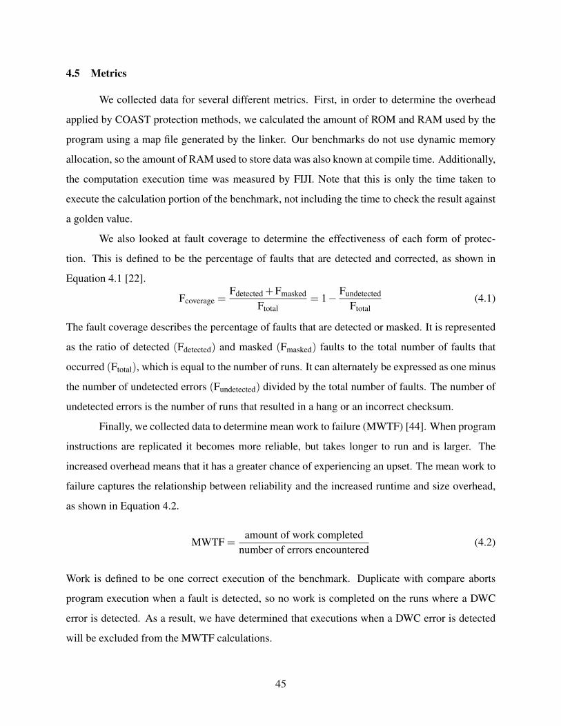
4.5 Metrics
We collected data for several different metrics. First, in order to determine the overhead
applied by COAST protection methods, we calculated the amount of ROM and RAM used by the
program using a map file generated by the linker. Our benchmarks do not use dynamic memory
allocation, so the amount of RAM used to store data was also known at compile time. Additionally,
the computation execution time was measured by FIJI. Note that this is only the time taken to
execute the calculation portion of the benchmark, not including the time to check the result against
a golden value.
We also looked at fault coverage to determine the effectiveness of each form of protec-
tion. This is defined to be the percentage of faults that are detected and corrected, as shown in
Equation 4.1 [22].
Fcoverage =Fdetected +Fmasked
Ftotal= 1− Fundetected
Ftotal(4.1)
The fault coverage describes the percentage of faults that are detected or masked. It is represented
as the ratio of detected (Fdetected) and masked (Fmasked) faults to the total number of faults that
occurred (Ftotal), which is equal to the number of runs. It can alternately be expressed as one minus
the number of undetected errors (Fundetected) divided by the total number of faults. The number of
undetected errors is the number of runs that resulted in a hang or an incorrect checksum.
Finally, we collected data to determine mean work to failure (MWTF) [44]. When program
instructions are replicated it becomes more reliable, but takes longer to run and is larger. The
increased overhead means that it has a greater chance of experiencing an upset. The mean work to
failure captures the relationship between reliability and the increased runtime and size overhead,
as shown in Equation 4.2.
MWTF =amount of work completed
number of errors encountered(4.2)
Work is defined to be one correct execution of the benchmark. Duplicate with compare aborts
program execution when a fault is detected, so no work is completed on the runs where a DWC
error is detected. As a result, we have determined that executions when a DWC error is detected
will be excluded from the MWTF calculations.
45

MWTF is used in place of the usual mean time to failure (MTTF) metric because it more
accurately models the trade off between reliability and performance. Doubling the run time while
halving the vulnerability to upsets yields the same MWTF, which allows us to determine if pro-
tection techniques truly yield an improvement. This is not captured in MTTF. Simply adding
multiple instructions would increase the MTTF without accounting for the larger program and
runtime. Additionally, the clones of the original instructions are not counted as work in order to
make fair comparisons between different protection methods. Although it is true that the processor
is executing many more instructions on code protected by TMR, it is still only generating a single
unique result. By defining work to be one execution of the benchmark, the results can be directly
compared.
4.6 Results
We tested the three benchmarks, both with and without automated data flow protection.
Faults were injected into random bits in the entirety of SRAM, including the stack and heap, at
random points in time while the benchmark did the computations, before it checked the results. We
used single bit upsets because the probability of a multiple bit upset in a radiation test using our
target platform is very low [7], and the purpose of this fault injection campaign was to model the
behavior in a radiation beam. The register files were not tested because an upset in the 2KB SRAM
was more probable than an upset in the 320 register bits, which total 1.9% of the total memory in
the system. All programs were linked and assembled using the msp-gcc compiler.
4.6.1 Effect of Configurations
Averages of the fault injection results for each configuration, relative to the baseline, are
illustrated in Figure 4.3 and listed in Table 4.1. Fault coverage is for the specified configuration
and is not relative. The table is divided into several portions, each corresponding to a general form
of protection. The numbers presented are averages between the three benchmarks. Each configu-
ration was tested with each benchmark for 5,000 injections into the SRAM, totaling 280,000 faults
injected over approximately 260 board-hours and three boards for this campaign. In this section
the data is first summarized, then unexpected results are discussed. Absolute results are presented
46
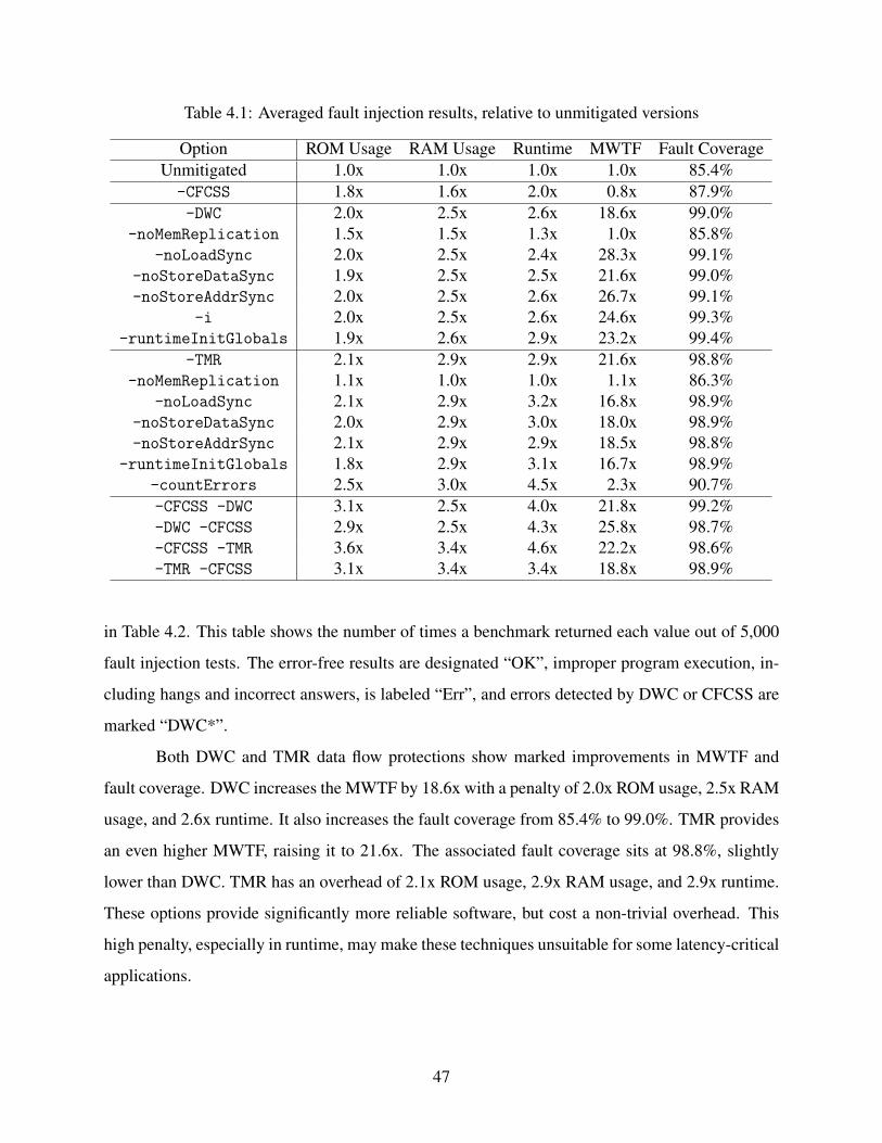
Table 4.1: Averaged fault injection results, relative to unmitigated versions
Option ROM Usage RAM Usage Runtime MWTF Fault CoverageUnmitigated 1.0x 1.0x 1.0x 1.0x 85.4%-CFCSS 1.8x 1.6x 2.0x 0.8x 87.9%-DWC 2.0x 2.5x 2.6x 18.6x 99.0%
-noMemReplication 1.5x 1.5x 1.3x 1.0x 85.8%-noLoadSync 2.0x 2.5x 2.4x 28.3x 99.1%
-noStoreDataSync 1.9x 2.5x 2.5x 21.6x 99.0%-noStoreAddrSync 2.0x 2.5x 2.6x 26.7x 99.1%
-i 2.0x 2.5x 2.6x 24.6x 99.3%-runtimeInitGlobals 1.9x 2.6x 2.9x 23.2x 99.4%
-TMR 2.1x 2.9x 2.9x 21.6x 98.8%-noMemReplication 1.1x 1.0x 1.0x 1.1x 86.3%
-noLoadSync 2.1x 2.9x 3.2x 16.8x 98.9%-noStoreDataSync 2.0x 2.9x 3.0x 18.0x 98.9%-noStoreAddrSync 2.1x 2.9x 2.9x 18.5x 98.8%
-runtimeInitGlobals 1.8x 2.9x 3.1x 16.7x 98.9%-countErrors 2.5x 3.0x 4.5x 2.3x 90.7%-CFCSS -DWC 3.1x 2.5x 4.0x 21.8x 99.2%-DWC -CFCSS 2.9x 2.5x 4.3x 25.8x 98.7%-CFCSS -TMR 3.6x 3.4x 4.6x 22.2x 98.6%-TMR -CFCSS 3.1x 3.4x 3.4x 18.8x 98.9%
in Table 4.2. This table shows the number of times a benchmark returned each value out of 5,000
fault injection tests. The error-free results are designated “OK”, improper program execution, in-
cluding hangs and incorrect answers, is labeled “Err”, and errors detected by DWC or CFCSS are
marked “DWC*”.
Both DWC and TMR data flow protections show marked improvements in MWTF and
fault coverage. DWC increases the MWTF by 18.6x with a penalty of 2.0x ROM usage, 2.5x RAM
usage, and 2.6x runtime. It also increases the fault coverage from 85.4% to 99.0%. TMR provides
an even higher MWTF, raising it to 21.6x. The associated fault coverage sits at 98.8%, slightly
lower than DWC. TMR has an overhead of 2.1x ROM usage, 2.9x RAM usage, and 2.9x runtime.
These options provide significantly more reliable software, but cost a non-trivial overhead. This
high penalty, especially in runtime, may make these techniques unsuitable for some latency-critical
applications.
47

(a) Overhead in ROM, RAM, and runtime
(b) MWTF and fault coverage.
Figure 4.3: Averaged fault injection results
48
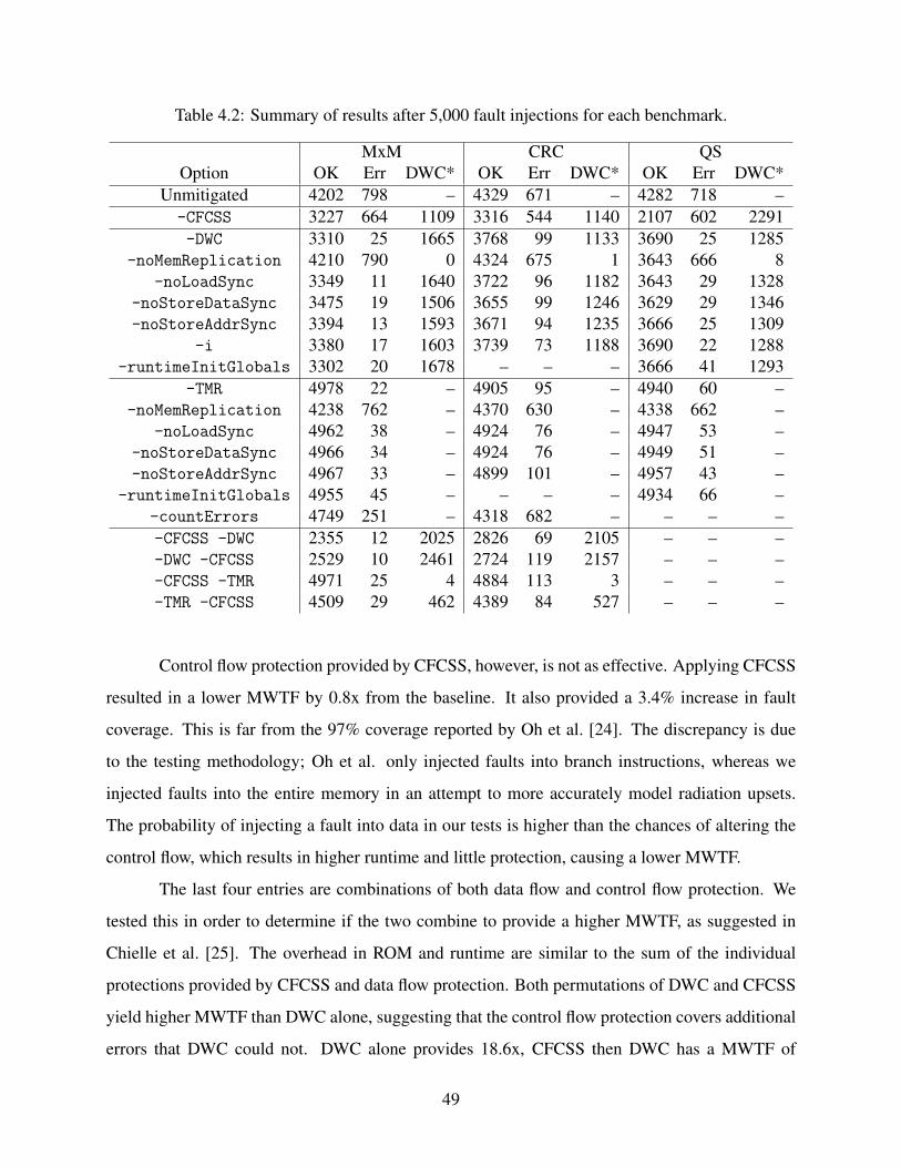
Table 4.2: Summary of results after 5,000 fault injections for each benchmark.
MxM CRC QSOption OK Err DWC* OK Err DWC* OK Err DWC*
Unmitigated 4202 798 – 4329 671 – 4282 718 –-CFCSS 3227 664 1109 3316 544 1140 2107 602 2291-DWC 3310 25 1665 3768 99 1133 3690 25 1285
-noMemReplication 4210 790 0 4324 675 1 3643 666 8-noLoadSync 3349 11 1640 3722 96 1182 3643 29 1328
-noStoreDataSync 3475 19 1506 3655 99 1246 3629 29 1346-noStoreAddrSync 3394 13 1593 3671 94 1235 3666 25 1309
-i 3380 17 1603 3739 73 1188 3690 22 1288-runtimeInitGlobals 3302 20 1678 – – – 3666 41 1293
-TMR 4978 22 – 4905 95 – 4940 60 –-noMemReplication 4238 762 – 4370 630 – 4338 662 –
-noLoadSync 4962 38 – 4924 76 – 4947 53 –-noStoreDataSync 4966 34 – 4924 76 – 4949 51 –-noStoreAddrSync 4967 33 – 4899 101 – 4957 43 –
-runtimeInitGlobals 4955 45 – – – – 4934 66 –-countErrors 4749 251 – 4318 682 – – – –-CFCSS -DWC 2355 12 2025 2826 69 2105 – – –-DWC -CFCSS 2529 10 2461 2724 119 2157 – – –-CFCSS -TMR 4971 25 4 4884 113 3 – – –-TMR -CFCSS 4509 29 462 4389 84 527 – – –
Control flow protection provided by CFCSS, however, is not as effective. Applying CFCSS
resulted in a lower MWTF by 0.8x from the baseline. It also provided a 3.4% increase in fault
coverage. This is far from the 97% coverage reported by Oh et al. [24]. The discrepancy is due
to the testing methodology; Oh et al. only injected faults into branch instructions, whereas we
injected faults into the entire memory in an attempt to more accurately model radiation upsets.
The probability of injecting a fault into data in our tests is higher than the chances of altering the
control flow, which results in higher runtime and little protection, causing a lower MWTF.
The last four entries are combinations of both data flow and control flow protection. We
tested this in order to determine if the two combine to provide a higher MWTF, as suggested in
Chielle et al. [25]. The overhead in ROM and runtime are similar to the sum of the individual
protections provided by CFCSS and data flow protection. Both permutations of DWC and CFCSS
yield higher MWTF than DWC alone, suggesting that the control flow protection covers additional
errors that DWC could not. DWC alone provides 18.6x, CFCSS then DWC has a MWTF of
49

21.8x, and DWC before CFCSS is at 25.8x. However, this effect is not as pronounced for TMR.
Running TMR before CFCSS provides a MWTF of 18.8x, whereas the MWTF of TMR alone is
21.6x. Running CFCSS first provides a slightly higher MWTF of 22.2x. The overhead of the two
methods together may counteract any gains in reliability, which would explain why MWTF does
not change significantly. Further research can examine the advantages of different combinations
of data flow options and control flow protections.
One might question why TMR and DWC do not yield infinite improvements in reliabil-
ity. This is not possible because of the architecture of our part. Scalar processors, such as the
MSP430, execute at most one instruction per clock cycle. This causes single points of failure to
exist at different windows of time while instructions occur before their copies. Additionally, some
portions of the memory region cannot be protected. For example, the stack return addresses and
peripheral registers cannot be protected without modifying the hardware. All of these factors limit
the reliability improvements that are possible.
There are gaps in the generated data. First, the -countErrors flag, which counts the
number of faults that TMR corrects, is not available for DWC because DWC halts on the first
error. Additionally, TMR does not work with interleaving (-i) on the MSP430FR5969 because
it overflows the stack for all benchmarks due to register pressure. The -runtimeInitGlobals
option, which performs a memcpy() call before execution, did not work properly on the CRC
benchmark. Likewise, the quicksort benchmark did not work with -countErrors or any of the
combinations of data flow and control flow protection. As far as we have been able to determine,
this is because of the stack overflowing into the global data. These values have been left out of the
results.
We observed that the RAM usage of DWC-related options is 2.5x the baseline, significantly
higher than the 2x one might expect. This is due to the abort() library call placed in the DWC
error handler, which is used to report a difference in checked values. This call includes a large
structure which is placed in RAM. If the abort() call is removed, then the RAM usage drops to
the expected 2.0x. Further experimentation is needed to determine if this structure alters the fault
tolerance of the program.
Another unexpected penalty with DWC-related options is the higher runtime. If every
instruction is duplicated then the runtime should increase by approximately 2.0x. DWC, how-
50

ever, has an associated runtime of 2.6x when measured. This is most likely due to the additional
control flow introduced with each synchronization point. Whenever two data points are synchro-
nized, the basic block must be split in two to account for a conditional jump to an error handler.
The MSP430FR5969 has a small instruction cache of four 64-bit lines [14]. Breaks in control
flow would invalidate the instruction cache, resulting in higher execution time while the processor
fetches the next instruction from FRAM, which is slower than SRAM.
The TMR ROM usage does not scale as one might expect. The code is 2.1x larger than
the baseline, whereas DWC uses 2.0x of the original program. The discrepancy can be explained
by the library functions linked into the final executable. The library containing abort() takes up
ROM as well as RAM, which accentuates the increase in DWC. Although the amount of user code
does triple, it is not the only code placed in ROM, so the overhead is masked.
Next, we looked at the -noMemReplication option, which does not replicate variables in
memory. It deviates significantly from the expected runtime. DWC and TMR increase runtime by
1.3x and 1.1x, respectively. Although store instructions are not replicated, the runtime should still
show a larger slowdown. From inspection of the disassembled code, it appears that the redundant
instructions have mostly been optimized away, although they are present in the LLVM IR. This
suggests that, even though the back end and assembler were not passed any optimization flags, a
tool stripped the redundant logic out. This is due to the fact that LLVM does not produce MSP430
binaries natively, which required us to use additional tools to assemble the code.
Another abnormality is that several options for TMR have slightly higher runtimes than
expected. Using -noLoadSync, -noStoreDataSync, and -noStoreAddrSync reduce the number
of synchronization points, which one might expect to decrease the runtime slightly from the orig-
inal 2.9x associated with TMR. Instead, we observed that they increase the runtime by 3.2x, 3.0x,
and 2.9x, respectively. There is no readily apparent reason for this. Our best suspicion is that the
synchronization point enabled a slightly more efficient combination of instructions, and removing
the checking logic caused the back end to schedule instructions differently, which caused a differ-
ence in runtime. Determining the root cause could be done by stepping through the disassembled
program code; however, this could take significant effort so we have not done this.
Finally, we noticed that the -countErrors flag, which is run in combination with TMR,
suffers from a large overhead and dramatically reduced MWTF. This option inserts logic to detect
51

Figure 4.4: MWTF across benchmarks and configurations.
how many times TMR corrects an error. The runtime jumps by 1.6x from the original TMR version.
This increase is most likely the culprit behind the reduction of MWTF by 9.4x from TMR. An
alternate form of this flag was tested, which conditionally incremented the counter instead of the
option described in Section 3.2.3, but the breaks in control flow caused an even greater penalty.
This penalty is important to note for the radiation test, as it suggests that errors in the RAM are
much more likely to be corrected by TMR than with TMR and error detection logic.
4.6.2 Benchmark Characteristics
The MWTF of across each benchmark and configuration is shown in Figure 4.4. There is a
general trend that the matrix multiplication benchmark benefits more from the data protection than
the other benchmarks. Another trend is that DWC tends to have a higher MWTF than the corre-
sponding TMR options. This is most likely due to the additional overhead that TMR introduces.
Additionally, removing synchronization points reduces the MWTF of the matrix multiplication,
but actually increases the reliability of quicksort. The MWTF of CRC is much lower than both of
them and is fairly constant. This suggests that the characteristics between the different benchmarks
52

have a significant impact on what types of protection are helpful. One possibility is a relationship
between the reliability of a benchmark and if it is memory- or compute-bounded. Future work
could investigate the source of these differences. One of the advantages of COAST is the ability to
quickly test different configurations and discover these relationships.
4.7 Chapter Summary
In conclusion, this fault injection campaign was able to uncover several interesting charac-
teristics of the different mitigation schemes. When faults are injected into memory, both DWC and
TMR increase the mean work to failure significantly. DWC has an overhead of 2.0x ROM usage,
2.5x RAM usage, and 2.6x runtime from a baseline. However, this provides an 18.6x increase in
MWTF, as well as 13.6% additional fault coverage. TMR has a penalty of 2.1x ROM usage, 2.9x
RAM usage, and 2.9x runtime. This extra overhead provides 21.6x higher MWTF and 13.4% more
fault coverage.
Several different protection methods have interesting side effects as well, such as linking
in libraries that increase RAM usage. The flag to detect errors in the radiation test also shows a
significant penalty in MWTF. The algorithms in the benchmarks benefit from different protection
schemes. Through fault injection into software protected by COAST, we have been able to estimate
the effectiveness of many of the different data protection techniques available.
53

CHAPTER 5. RADIATION TESTING
After verifying our passes through fault injection, we moved to radiation testing. Radiation
testing is the golden standard for modeling how the system will work when deployed in a high-
radiation environment [40]. Although fault injection is useful, it is limited by the tool in its scope
of injections. For example, our fault injection tool is unable to inject faults into the processor logic
while instructions are executing. A radiation beam has no such limitations. Additionally, it can
model the types of radiation that software would experience when deployed in space. For instance,
the neutron beam at Los Alamos Neutron Science Center (LANSCE) has been shown to simulate
the energy spectrum of terrestrial radiation [9].
5.1 Goals of Radiation Testing
The goal of irradiating the microcontrollers in a controlled environment was to verify that
the protection provided by COAST was effective and comparable to previous work. Increasing
the mean work to failure (MWTF) by more than 1x indicates successful program protection, as
this means that more work is completed before an upset. It also indicates that, although TMR
introduces an overhead that will make it more vulnerable to faults, it causes an increase in reliability
that more than offsets that overhead. We measure the effectiveness of the mitigation by repeatedly
running several benchmarks in a neutron beam. The results of each execution are logged. A DUT
can experience errors, hang, or run normally. We use these results to calculate the vulnerability
and MWTF of the processor.
5.2 Test Setup
We used the same Texas Instruments MSP430FR5969 microcontrollers [14] that we tested
with fault injection, as described in Section 4.2. These boards have also been tested in a beam
by Quinn et al. [15]. We attended LANSCE in November of 2017 and placed our boards in the
54

Irradiation of Chips and Electronics (ICE) neutron flight path at an incidence of 30 degrees. The
beam was collimated to two inches and the experiments took place over one week.
As described in Section 4.2, the MSP430FR5969 is a 16-bit microcontroller running at 16
MHz with 2KB of SRAM memory and 64KB of FRAM to store the program instructions. One of
the benefits of using this microcontroller is that it is FRAM-based, meaning that the program code
is inherently hardened against radiation upsets [45]. The 15 MSP430FR5969s were deployed on
Texas Instruments EXP430FR5969 development boards [6] in three “bricks” of five boards each,
as shown in Figure 5.1.
Figure 5.1: Picture of MSP430 boards at LANSCE neutron test.
Figure 5.2 contains a block diagram of the basic testing setup. Note that this diagram shows
only one brick of the three. The test consists of several elements:
MSP430 The DUT. Each brick contained five boards, but the monitoring Raspberry Pi only had 4
USB ports. As a result, we connected additional wires to share the power and programming
signals between two boards. In Figure 5.1 the wire connecting the two rightmost boards in
each brick is sharing one of these signals.
Raspberry Pi Each brick was programmed by and reported execution statuses to a Raspberry Pi
3. The Raspberry Pi had many desirable characteristics. First and foremost, the general
55
Figure 5.2: Diagram of the radiation test setup.
purpose input/output (GPIO) allowed us to communicate with the MSP430s without relying
on slower UART commands. The Raspberry Pis run at 1.2GHz, compared to the 16 MHz
of the MSP430s, so the logging software could keep up as results were produced. Addition-
ally, the hosted Linux operating system allowed us to periodically transfer logs to a remote
location. The Raspberry Pis could also toggle power to the onboard USB ports via software
commands, allowing each to automatically power cycle MSP430s as needed.
Power Strip On occasion the Raspberry Pis would experience errors and become unresponsive.
An Ethernet-enabled Netbooter power strip was used to manually power cycle the affected
Pi.
NUC PC The three Raspberry Pis were connected to a NUC computer running Linux. It collected
the logs from the Raspberry Pis periodically and monitored their statuses.
A photo of the radiation test is shown in Figure 5.2. The MSP430 boards are the red boards in the
foreground, and the beam cap is visible at the top of the picture.
In order to obtain program results, we instrumented all benchmarks with code which re-
ported the status at the end of each execution, as illustrated in Figure A.4 in Appendix A. Quinn
et al. have found that printing status messages during a radiation test can cause irregular measure-
ments because of the extra processing time needed [18]. To avoid this problem we opted to use
56
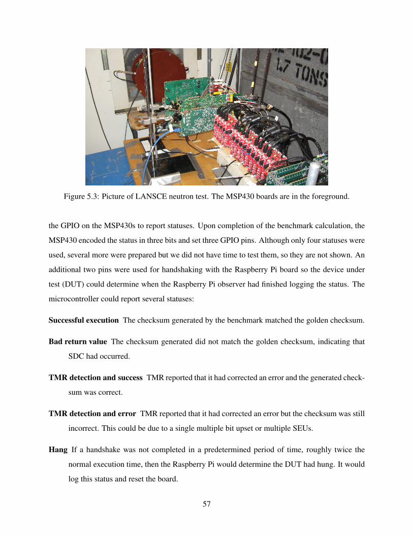
Figure 5.3: Picture of LANSCE neutron test. The MSP430 boards are in the foreground.
the GPIO on the MSP430s to report statuses. Upon completion of the benchmark calculation, the
MSP430 encoded the status in three bits and set three GPIO pins. Although only four statuses were
used, several more were prepared but we did not have time to test them, so they are not shown. An
additional two pins were used for handshaking with the Raspberry Pi board so the device under
test (DUT) could determine when the Raspberry Pi observer had finished logging the status. The
microcontroller could report several statuses:
Successful execution The checksum generated by the benchmark matched the golden checksum.
Bad return value The checksum generated did not match the golden checksum, indicating that
SDC had occurred.
TMR detection and success TMR reported that it had corrected an error and the generated check-
sum was correct.
TMR detection and error TMR reported that it had corrected an error but the checksum was still
incorrect. This could be due to a single multiple bit upset or multiple SEUs.
Hang If a handshake was not completed in a predetermined period of time, roughly twice the
normal execution time, then the Raspberry Pi would determine the DUT had hung. It would
log this status and reset the board.
57

An example of the tested matrix multiplication benchmark is shown in Figure 5.4. This has
been slightly modified from the original code found in Figure A.2 in Appendix A. The unchanged
computation code has been removed for brevity, leaving several modifications that have been made
for the radiation test. First, there are two new functions, setupPins() and resetPins() on
lines 7 and 15, respectively. These functions are needed to interface with the GPIO. The matrix
multiplication and checking code are identical to those found in Figure 5.4. The main() function
in line 27, however, is significantly different. It now initializes pins, then enters an infinite loop.
It resets the GPIO pins on line 32, executes the multiplication, and checks the results. It then sets
the appropriate GPIO pins using the logic beginning on line 35 and waits for an acknowledgement
from the Raspberry Pi. The loop executes until an error is detected; the monitoring Raspberry Pi
then reprograms the board and execution continues.
5.3 Metrics
We used many of the same metrics used in Chapter 4. However, it is impossible to know
when a fault has been introduced into the system, so fault coverage was not included. Additionally,
another benchmark, cross section, has been introduced. These are explained more in detail below.
Code size The amount of FRAM used by the program.
RAM size The amount of RAM used by the program, as determined at link time. Memory is not
dynamically allocated by the benchmarks, so this is fixed at compile time.
Runtime The execution time of the benchmark.
MWTF As before, the mean work to failure captures the balance between increased runtime and
reliability. However, because the upsets are stochastic, the calculation must be modified
from Equation 4.2 to Equation 5.1. A unit of work is defined to be one execution of the
benchmark.
MWTF =number of correct executions
number of incorrect results+number of hangs(5.1)
58

1 # i n c l u d e ‘ ‘ r a d i a t i o n T e s t . h ’ ’2 u n s i g n e d i n t f i r s t m a t r i x [ 9 ] [ 9 ] = { . . . } ;3 u n s i g n e d i n t s e c o n d m a t r i x [ 9 ] [ 9 ] = { . . . } ;4 u n s i g n e d i n t x o r g o l d e n = 46324 ;5 u n s i g n e d i n t r e s u l t s m a t r i x [ 9 ] [ 9 ] ;6 vo id s e t u p P i n s ( ) {7 WDTCTL = WDTPW | WDTHOLD; / / S top WDT8 PM5CTL0 = PM5CTL0 & ˜LOCKLPM5; / / Keep GPIO s e t t i n g s9 ACK DIR &= ˜ ACK PIN ; / / S e t a l l p i n s low
10 DONE DIR |= DONE PIN ; SEL DIR |= SEL PIN0 ;11 SEL DIR |= SEL PIN1 ; SEL DIR |= SEL PIN2 ;12 LED DIR |= LED PIN ; LED PORT &= ˜ LED PIN ; }13
14 vo id r e s e t P i n s ( ) { / / s e t a l l o f t h e s t a t u s p i n s t o be low15 DONE PORT &= ˜ DONE PIN ; SEL PORT &= ˜ SEL PIN0 ;16 SEL PORT &= ˜ SEL PIN1 ; SEL PORT &= ˜ SEL PIN2 ; }17
18 vo id m a t r i x m u l t i p l y ( u n s i g n e d i n t f m a t r i x [ ] [ 9 ] , u n s i g n e d i n t s m a t r i x [ ] [ 9 ] ,u n s i g n e d i n t r m a t r i x [ ] [ 9 ] ) {
19 . . .20 }21 i n t checkGolden ( ) {22 . . .23 }24 i n t main ( ) {25 i n t numErrors ;26 s e t u p P i n s ( ) ;27 w h i l e ( 1 ) { / / Run f o r e v e r28 LED PORT ˆ= LED PIN ; / / B l i n k t h e LED29 r e s e t P i n s ( ) ;30 m a t r i x m u l t i p l y ( f i r s t m a t r i x , s e c o n d m a t r i x , r e s u l t s m a t r i x ) ;31 numErrors = checkGolden ( ) ;32 i f ( numErrors ) {33 i f (NO TMR ERROR) s e t S t a t u s ( b a d v a l u e ) ;34 e l s e s e t S t a t u s ( t m r d e t e c t a n d e r r o r ) ;35 } e l s e {36 i f (NO TMR ERROR) s e t S t a t u s ( s u c c e s s ) ;37 e l s e s e t S t a t u s ( t m r d e t e c t a n d s u c c e s s ) ;38 }39 wai tForAck ( ) ;40 }41 }
Figure 5.4: Radiation test matrix multiplication benchmark.
Cross section The cross section of a program refers to the probability of an upset occurring. The
basic formula for calculating the cross section, σ , is shown in Equation 5.2.
σ =eventsfluence
(5.2)
59

The radiation effects community uses 95% confidence intervals by convention [46]. When
there are 50 or more events, this confidence interval can be calculated using the bounds show
in Equation 5.3.
± 2∗√
eventsfluence
(5.3)
Some devices have extremely small cross sections, making it difficult to obtain 50 events. In
this case, the Poisson error bars [47] are used.
5.4 Results
The MSP430FR5969 has a very small cross section in a neutron beam [15]. This limited
the number of configurations we could test in the beam. Even with five days of testing, and up
to 15 boards in the beam simultaneously, we could only gather sufficient data to reduce the error
bars for a few program configurations. With this in mind, we chose to test the matrix multiply and
CRC checksum benchmarks used in fault injection, as described in Section 4.4. Each of these had
hard coded inputs and a golden checksum for comparison. The CRC took the checksum of a 560
character array, then compared it to a known golden value.
Each program was tested unmitigated and with TMR applied. The TMR used the default
setting of COAST, with the addition of the -countErrors flag to be able to detect when TMR
corrected a fault. This unconditionally loaded a global flag, set it if a fault was detected, then
stored it on every synchronization point. This is explained more in Section 3.2.3. As shown in
Chapter 4 this option can decrease the MWTF of TMR. However, it provides necessary information
to understand how TMR affects both fault and error sensitivity in the design.
The overhead that TMR, along with the fault detection logic, causes in code size, RAM
usage, and runtime is shown in Table 5.1. These numbers are similar to those found in Chapter 4.
The results encountered for each program are enumerated in Table 5.2. Total executions
refers to the number of times the benchmark was executed across all boards. Corrected faults
occurred when TMR detected a fault and returned a correct result. SDC errors occurred whenever
the computed checksum did not match the golden value. This includes runs where TMR corrected
an error but still returned an incorrect result. On occasion the DUT would become unresponsive,
resulting in a hang. Finally, the boards returned an invalid status a few times. Each possible return
60

Table 5.1: Radiation test benchmark characteristics.
BenchmarkCode size
(bytes)RAM size
(bytes)Runtime
(ms)
MxM Unmit. 1752 524 107MxM TMR 5716 1830 402Increase 3.3x 3.5x 3.8x
CRC Unmit. 1752 568 44CRC TMR 4288 1972 178Increase 2.4x 3.5x 3.9x
value from the MSP430s were represented in three bits. However, not all combinations were used.
The Raspberry Pis logged some of these unused return values a handful of times across the test.
We do not know the exact cause, but believe that a radiation upset affected the reporting logic.
The final column represents the total fluence, or number of neutrons per square centimeter, each
program was exposed to.
Table 5.2: Program results from neutron beam test.
BenchmarkTotal
ExecutionsCorrected
FaultSDC
Errors HangsInvalidStatus
Fluence(n/cm2)
MxM Unmit. 7665806 – 40 5 1 3.8×10¹¹
MxM TMR 5410937 291 4 7 2 1.1×10¹²
CRC Unmit. 5924316 – 30 0 1 2.1×10¹¹
CRC TMR 3380543 159 4 3 2 4.8×10¹¹
The results in Table 5.3 are reliability estimates derived from Tables 5.1 and 5.2. The first
metric, MWTF, shows that the matrix multiplication with TMR applied was able to, on average,
complete 7.1x more work between failures. The CRC benchmark likewise showed a 4.3x improve-
ment in MWTF, for an average of 5.7x between the two programs. This is greater than 1x, meaning
that automated TMR improved the reliability of the software in the beam.
The results of the fault injection campaign in Chapter 4 also show that TMR increases
MWTF. However, on average, it increased by 2.3x on average in simulation for TMR with error
reporting logic. Although the fault injection test would appear to perform more poorly than the
61

Table 5.3: Reliability results from neutron beam test.
Benchmark MWTFSDC Cross
Section (cm2)95% ConfidenceInterval (cm2)
MxM Unmit. 191644 1.07×10⁻¹⁰ (3.04×10⁻¹¹, 2.52×10⁻¹⁰)MxM TMR 1352658 3.72×10⁻¹² (2.79×10⁻¹², 1.32×10⁻¹¹)Improvement: 7.1x 28.7x –
CRC Unmit. 197476 1.43×10⁻¹⁰ (4.66×10⁻¹¹, 3.46×10⁻¹⁰)CRC TMR 845094 8.18×10⁻¹² (6.14×10⁻¹², 2.91×10⁻¹¹)Improvement: 4.3x 17.4x –
radiation test, this is not necessarily the case. The two cannot be directly compared because of
the difference of where faults can be introduced. The fault injection tests were limited to the
SRAM, but the radiation beam has no such limits. Program registers, SRAM, and even processor
structures may receive upsets. Although the two numbers are related, a difference between the two
is expected. Additionally, because the error reporting logic decreased the MWTF of TMR in fault
injection, it is possible that it likewise decreased the MWTF of TMR in this radiation test. The
actual MWTF of software TMR without error reporting in the neutron beam might be higher than
reported. Finally, the code used to communicate with the Raspberry Pis using the GPIO might
introduce extra overhead, which could increase the vulnerability of the program.
In addition to MWTF, Table 5.3 also shows the cross sections for errors along with the 95%
confidence intervals for each program. The unmitigated cross section is similar to other reported
unmitigated cross sections of our DUT [15]. TMR decreases the SDC cross section of the matrix
multiplication benchmark by 28.7x. The CRC program shows a decrease of 17.4x. Together, TMR
decreases the error cross section by an average of 23.1x. Because the cross section measures the
likelihood of an upset, a lower value corresponds to a program that is less susceptible to errors.
The error and fault cross sections for each design, along with the 95% confidence intervals,
are plotted in Figure 5.5. The blue squares represent the probabilities of errors in the design, which
occur when the program did not perform as expected. The red circles indicate faults which were
corrected and did not become errors. Faults and errors are the same in unmitigated versions.
The chart shows that the unmitigated matrix multiplication and CRC designs have simi-
lar error cross sections, although the CRC benchmark has a larger cross section in general. As
62

Figure 5.5: Design cross sections.
expected, TMR increases the fault cross section because of the overhead in RAM usage and ex-
ecution time exposes each run to more fluence, increasing the chance of an upset. However, as
shown in Table 5.3, the error cross section for the mitigated versions is less than the error cross
section of the unmitigated design. This indicates that TMR can effectively reduce the cross section
of a program, making it less likely to experience upsets. It also dramatically increases the runtime,
code size, and memory usage.
5.4.1 Comparison with Previous Work
Comparison with previous work is difficult because methodologies vary greatly between
works. Chielle et al. [25] tested VAR3+ data flow protection [1] and SETA control flow mitiga-
tion [25] on a Tower of Hanoi benchmark running on a ZedBoard in a heavy ion beam. These
techniques combined to provide a 1.66x increase in MWTF on their hardened application. When
this setup was tested in the neutron beam at LANSCE the program showed a 1.61x increase in
mean work to failure [23]. In comparison, software protected by COAST showed an average in-
crease in MWTF by 5.7x. There are likely two reasons for this discrepancy. First and foremost,
the VAR3+ method does not protect anything in memory, whereas the default setting of COAST is
to replicate all loads and stores. Additionally, as the authors point out in [25], the cache memories
63
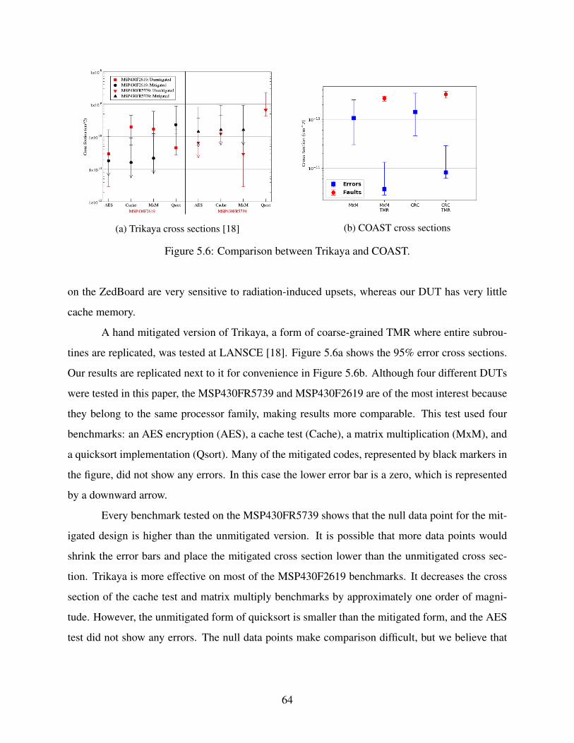
(a) Trikaya cross sections [18] (b) COAST cross sections
Figure 5.6: Comparison between Trikaya and COAST.
on the ZedBoard are very sensitive to radiation-induced upsets, whereas our DUT has very little
cache memory.
A hand mitigated version of Trikaya, a form of coarse-grained TMR where entire subrou-
tines are replicated, was tested at LANSCE [18]. Figure 5.6a shows the 95% error cross sections.
Our results are replicated next to it for convenience in Figure 5.6b. Although four different DUTs
were tested in this paper, the MSP430FR5739 and MSP430F2619 are of the most interest because
they belong to the same processor family, making results more comparable. This test used four
benchmarks: an AES encryption (AES), a cache test (Cache), a matrix multiplication (MxM), and
a quicksort implementation (Qsort). Many of the mitigated codes, represented by black markers in
the figure, did not show any errors. In this case the lower error bar is a zero, which is represented
by a downward arrow.
Every benchmark tested on the MSP430FR5739 shows that the null data point for the mit-
igated design is higher than the unmitigated version. It is possible that more data points would
shrink the error bars and place the mitigated cross section lower than the unmitigated cross sec-
tion. Trikaya is more effective on most of the MSP430F2619 benchmarks. It decreases the cross
section of the cache test and matrix multiply benchmarks by approximately one order of magni-
tude. However, the unmitigated form of quicksort is smaller than the mitigated form, and the AES
test did not show any errors. The null data points make comparison difficult, but we believe that
64
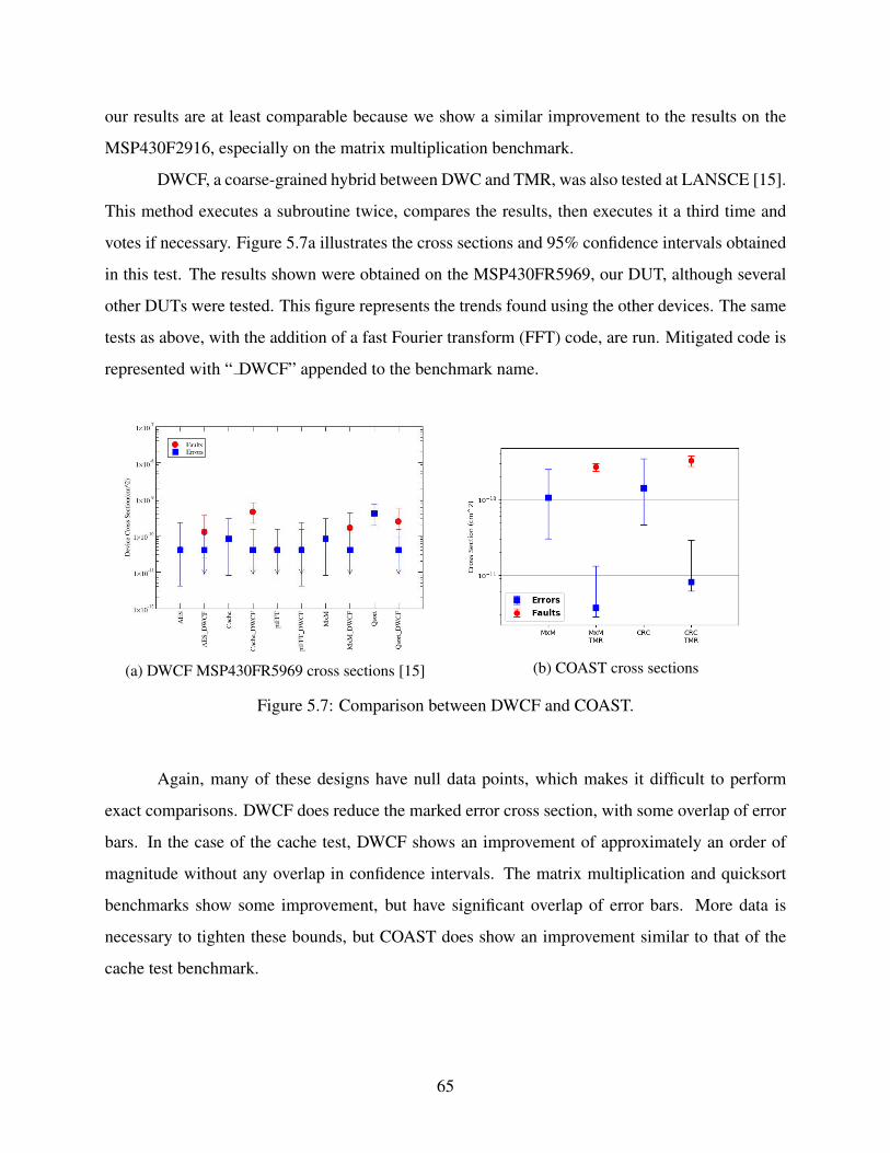
our results are at least comparable because we show a similar improvement to the results on the
MSP430F2916, especially on the matrix multiplication benchmark.
DWCF, a coarse-grained hybrid between DWC and TMR, was also tested at LANSCE [15].
This method executes a subroutine twice, compares the results, then executes it a third time and
votes if necessary. Figure 5.7a illustrates the cross sections and 95% confidence intervals obtained
in this test. The results shown were obtained on the MSP430FR5969, our DUT, although several
other DUTs were tested. This figure represents the trends found using the other devices. The same
tests as above, with the addition of a fast Fourier transform (FFT) code, are run. Mitigated code is
represented with “ DWCF” appended to the benchmark name.
(a) DWCF MSP430FR5969 cross sections [15] (b) COAST cross sections
Figure 5.7: Comparison between DWCF and COAST.
Again, many of these designs have null data points, which makes it difficult to perform
exact comparisons. DWCF does reduce the marked error cross section, with some overlap of error
bars. In the case of the cache test, DWCF shows an improvement of approximately an order of
magnitude without any overlap in confidence intervals. The matrix multiplication and quicksort
benchmarks show some improvement, but have significant overlap of error bars. More data is
necessary to tighten these bounds, but COAST does show an improvement similar to that of the
cache test benchmark.
65

5.5 Chapter Summary
Overall, the results provided by automated protection show an improvement when tested
in a radiation beam, both in mean work to failure and in reduction of cross section. Although
direct comparison is difficult, we believe that the demonstrated improvement is at least similar to
other, state-of-the-art mitigation techniques. Results from this test show a mean increase of MWTF
by 5.7x and a mean decrease in cross section by 17.4x when TMR is applied with error detecting
logic. The combination of the two has been shown to have higher overhead and lower effectiveness
than TMR alone, suggesting that TMR alone may provide even higher levels of protection. This
illustrates that automated TMR, applied by COAST, can be an effective form of protection against
silent data corruption.
66

CHAPTER 6. CONCLUSION
Radiation can have any number of ill effects on computing systems in space. Although
radiation-hardened platforms are available, COTS microcontrollers tend to be smaller, faster, inex-
pensive, and require less power. In order to use these microcontrollers on spacebourne platforms
some form of error detection or correction must be implemented.
This thesis has explored fully automated software-based mitigation to improve the relia-
bility of microcontrollers and microcontroller software in a high radiation environment. We have
examined and implemented several different fault tolerance techniques from previous works. In
the pursuit of an automated solution, several problems arose when calling unprotected functions
from protected functions. The solutions to these issues have been presented. Additionally, the
COAST (COmpiler-Assisted Software fault Tolerance) tool has been introduced, along with its
many different configurations.
Control flow protection is implemented using CFCSS, which decreases the mean work to
failure to 0.8x the original value when tested alone using a fault injection campaign. Additionally,
data flow protection is provided in the form of duplication with compare and triple modular redun-
dancy. DWC gives a 18.6x increase in mean work to failure across thousands of fault injections.
TMR was likewise tested and showed an increase in mean work to failure of 21.6x. Combining
CFCSS and data flow protection methods yielded increases in MWTF between 18.8x to 25.8x.
When further tested in a neutron beam, the mean work to failure increased by an average of 5.7x.
The cross-section decreased by an average of 17.4x. These tests demonstrate that software miti-
gated by these techniques is more reliable in high radiation environments.
67
6.1 Future Work
Although COAST is a good starting point for automated protection, there is still room for
improvement. These will increase the utility and ease of use of the mitigation passes. A list of
these potential improvements is given here as a starting point for further work.
Eliminate Single Points of Failure A single point of failure is a part of the program that, when
corrupted, results in an unrecoverable error or SDC. Values returned by functions are used in
all replicated instructions, introducing a single point of failure. To remedy this, the function
signature can be automatically modify to include variables, passed-by-pointer in arguments,
that could serve as return values. Other single points of failure include library calls that only
occur once, including calls that involve external I/O. Additionally, each control flow point is
a single point of failure. More work can be done to examine how to harden these vulnerable
areas.
Additional Forms of Data Flow Mitigation Currently, two customizable forms of data flow pro-
tection and one form of control flow protection are implemented. However, many other
forms of protection have been proposed. Further work could explore implementing control
flow methods such as SETA [23] and ACCE [29]. Some promising data flow protection
methods are TRUMP/MASK [17] or nZDC [13]. These could potentially increase reliability
beyond basic TMR. Future work could also analyze the effect of integrating data flow and
control flow methods. Finally, the overhead of both execution and program space can be
reduced [15], [48], [49], which would improve the reliability of protection methods. This
could be combined with code profiling to only replicate crucial instructions [50]. If COAST
supported these methods then it would be extremely easy to quickly test the effectiveness of
different protections, allowing for the most reliable software to be used for space missions.
Alternate Forms of Control Flow Mitigation We have currently tested CFCSS as a main form
of control flow protection. Other forms of mitigation, such as a watchdog timer or NOP
sled, could potentially be effective. These do not have the program overhead associated with
a pure software technique. Additionally, they could help reduce the number of processor
hangs.
68

Power Cost Analysis This thesis did not analyze the power usage of each form of mitigation. This
is a nontrivial aspect, especially on space platforms, and should be explored further. Longer
calculations and more frequent memory accesses can increase the power consumed by the
microcontroller beyond the allocated power budget.
Analysis of Algorithmic Reliability As discussed in Chapter 4, fault tolerance schemes work bet-
ter for some benchmarks than others. More research would help uncover the relationship
between data access patterns and the corresponding ideal mitigation techniques.
Testing on Additional Platforms By relying on LLVM, COAST is able to support multiple tar-
gets. Software for the ARM-based MSP432 microcontroller has been tested on COAST,
but there has not been any exhaustive fault injection campaign like there has been for the
MSP430. Testing the effectiveness of automated mitigation across multiple platforms, in-
cluding soft processors on field programmable gate arrays (FPGAs), will further show the
benefit of this tool.
Configuration Files COAST allows the user to specify how library function calls should be han-
dled. However, this can be tedious and error-prone. The next step for the software devel-
opment is to allow for configuration files to be used, in addition to command line options.
These files would have library calls categorized into how they should be treated, allowing
the user to have more control over replication.
As development continues, I hope that COAST will be a convenient tool to rapidly and
automatically test different forms of software mitigation for microcontrollers and other platforms.
This tool should be especially helpful to those who, because of project constraints, cannot apply
other hardware mitigation techniques. Alternately, this is also a helpful solution to platforms that
have already been deployed and are experiencing problems with SEUs. Our hope is that users of
COAST can rapidly explore many forms of fault tolerance to strike the balance between protection
and performance as needed for their application. As these different software mitigation techniques
are applied, the risk of radiation upsets is decreased, allowing for space missions with more reliable
operation and data gathering.
69
REFERENCES
[1] E. Chielle, F. L. Kastensmidt, and S. Cuenca-Asensi, “Overhead reduction in data-flow software-based fault tolerance techniques,” in FPGAs and Parallel Architectures forAerospace Applications: Soft Errors and Fault-Tolerant Design. Cham: Springer Interna-tional Publishing, 2015, pp. 279–291. vi, 4, 11, 12, 26, 27, 36, 63
[2] H. Quinn, T. Fairbanks, J. L. Tripp, and A. Manuzzato, “The reliability of software algorithmsand software-based mitigation techniques in digital signal processors,” in IEEE RadiationEffects Data Workshop. IEEE, July 2013, pp. 1–8. vii, 1, 7
[3] S. S. Mukherjee, J. Emer, and S. K. Reinhardt, “The soft error problem: An architectural per-spective,” in International Symposium on High-Performance Computer Architecture. IEEE,2005, pp. 243–247. vii, 7, 8
[4] G. A. Reis, J. Chang, N. Vachharajani, R. Rangan, and D. I. August, “SWIFT: Softwareimplemented fault tolerance,” in International Symposium on Code Generation and Opti-mization. IEEE, 2005, pp. 243–254. vii, 2, 3, 10, 15, 23
[5] A. Shrivastava, A. Rhisheekesan, R. Jeyapaul, and C. Wu, “Quantitative analysis of con-trol flow checking mechanisms for soft errors,” Design Automation Conference on DesignAutomation Conference, pp. 1–6, 2014. vii, 14, 15, 19
[6] Texas Instruments, “MSP430FR5969 LaunchPad Development Kit (MSPEXP430FR5969),”Tech. Rep. SLAU535b. [Online]. Available: http://www.ti.com/lit/ug/slau535b/slau535b.pdfvii, 40, 55
[7] H. Quinn, T. Fairbanks, J. L. Tripp, G. Duran, and B. Lopez, “Single-event effects in low-cost, low-power microprocessors,” in Radiation Effects Data Workshop. IEEE, July 2014,pp. 1–9. 1, 15, 28, 46
[8] E. Chielle, R. S. Barth, A. C. Lapolli, and F. L. Kastensmidt, “Configurable tool to protectprocessors against SEE by software-based detection techniques,” in IEEE Latin AmericanTest Workshop. IEEE, Apr. 2012, pp. 1–6. 1, 3, 16
[9] H. Quinn and P. Graham, “Terrestrial-based radiation upsets: A cautionary tale,” in Sympo-sium on Field-Programmable Custom Computing Machines, vol. 2005. IEEE, 2005, pp.193–202. 1, 6, 54
[10] F. Sturesson, “Single event effects (SEE) mechanism and effects,” pp. 1–32, 2009. [On-line]. Available: http://space.epfl.ch/webdav/site/space/shared/industry media/07%20SEE%20Effect%20F.Sturesson.pdf 1, 6
70

[11] N. Oh, P. P. Shirvani, and E. J. McCluskey, “Error detection by duplicated instructions insuper-scalar processors,” IEEE Transactions on Reliability, vol. 51, no. 1, pp. 63–75, Mar.2002. 2, 9, 19, 22, 28, 30, 39
[12] C. Fetzer, U. Schiffel, and M. Sußkraut, “An-encoding compiler: Building safety-criticalsystems with commodity hardware,” in International Conference on Computer Safety, Relia-bility, and Security. Berlin, Heidelberg: Springer-Verlag, 2009, pp. 283–296. 2, 9, 16
[13] M. Didehban and A. Shrivastava, “nZDC : A compiler technique for near zero silent dataCorruption,” in Design Automation Conference. New York, New York, USA: ACM Press,2016, pp. 1–6. 2, 10, 16, 39, 68
[14] Texas Instruments, “MSP430FR59xx Mixed-Signal Microcontrollers,” Tech. Rep.SLAS704F. [Online]. Available: http://www.ti.com/lit/ds/symlink/msp430fr5969.pdf 2,40, 51, 54
[15] H. Quinn, Z. Baker, T. Fairbanks, J. L. Tripp, and G. Duran, “Robust duplication with com-parison methods in microcontrollers,” IEEE Transactions on Nuclear Science, vol. 64, no. 1,pp. 338–345, Jan. 2017. 2, 3, 24, 40, 54, 60, 62, 65, 68
[16] M. Rebaudengo, M. S. Reorda, and M. Violante, “A new approach to software-implementedfault tolerance,” in Journal of Electronic Testing: Theory and Applications (JETTA), vol. 20,no. 4. Kluwer Academic Publishers, Aug. 2004, pp. 433–437. 2, 15, 23, 39
[17] J. Chang, G. Reis, and D. August, “Automatic instruction-level software-only recovery,” inInternational Conference on Dependable Systems and Networks. IEEE, 2006, pp. 83–92.2, 12, 13, 16, 19, 22, 39, 68
[18] H. Quinn, Z. Baker, T. Fairbanks, J. L. Tripp, and G. Duran, “Software resilience and theeffectiveness of software mitigation in microcontrollers,” in IEEE Transactions on NuclearScience, vol. 62, no. 6, Dec. 2015, pp. 2532–2538. 2, 3, 4, 12, 13, 16, 19, 23, 24, 30, 56, 64
[19] E. Chielle, “Selective Software-Implemented Hardware Fault Tolerance Techniques to DetectSoft Errors in Processors with Reduced Overhead,” Ph.D. dissertation, July 2016. 3
[20] C. Wang, H. S. Kim, Y. Wu, and V. Ying, “Compiler-managed software-based redundantmulti-threading for transient fault detection,” in International Symposium on Code Genera-tion and Optimizations. IEEE, Mar. 2007, pp. 244–256. 3, 16
[21] C. Lattner and V. Adve, “LLVM: A compilation framework for lifelong program analysis &transformation,” Proceedings of the IEEE International Symposium on Code Generation andOptimization: Feedback-directed and Runtime Optimization, p. 325, 2004. 3, 16, 17
[22] E. Chielle, F. Rosa, G. S. Rodrigues, L. A. Tambara, F. L. Kastensmidt, R. Reis, andS. Cuenca-Asensi, “Reliability on ARM processors against soft errors by a purely softwareapproach,” in European Conference on Radiation and its Effects on Components and Systems.IEEE, Dec. 2015, pp. 1–5. 3, 11, 27, 45
[23] E. Chielle, G. S. Rodrigues, F. L. Kastensmidt, S. Cuenca-Asensi, L. A. Tambara, P. Rech,and H. Quinn, “S-SETA: Selective software-only error-detection technique using assertions,”
71

in IEEE Transactions on Nuclear Science, vol. 62, no. 6, Dec. 2015, pp. 3088–3095. 3, 11,27, 39, 63, 68
[24] N. Oh, P. P. Shirvani, and E. J. McCluskey, “Control-flow checking by software signatures,”IEEE Transactions on Reliability, vol. 51, no. 1, pp. 111–122, Mar. 2002. 3, 14, 19, 24, 49
[25] E. Chielle, F. Rosa, G. S. Rodrigues, L. A. Tambara, J. Tonfat, E. Macchione, F. Aguirre,N. Added, N. Medina, V. Aguiar, M. A. Silveira, L. Ost, R. Reis, S. Cuenca-Asensi, and F. L.Kastensmidt, “Reliability on ARM processors against soft errors through SIHFT techniques,”IEEE Transactions on Nuclear Science, vol. 63, no. 4, pp. 2208–2216, 2016. 4, 11, 15, 49,63
[26] M. O’Bryan, “Single Event Effects,” Nov 2015. [Online]. Available: https://radhome.gsfc.nasa.gov/radhome/see.htm 6
[27] A. Avizienis, J. C. Laprie, B. Randell, and C. Landwehr, “Basic concepts and taxonomy ofdependable and secure computing,” IEEE Transactions on Dependable and Secure Comput-ing, vol. 1, no. 1, pp. 11–33, Jan. 2004. 7
[28] J. R. Azambuja, A. Lapolli, M. M. Altieri, and F. L. Kastensmidt, “Evaluating the effi-ciency of data-flow software-based techniques to detect SEEs in microprocessors,” in Latin-American Test Workshop. IEEE, Mar. 2011, pp. 1–6. 11, 39
[29] R. Vemu, S. Gurumurthy, and J. A. Abraham, “ACCE: Automatic correction of control-flowerrors,” in International Test Conference. IEEE, 2008, pp. 1–10. 16, 39, 68
[30] “LLVM language reference manual.” [Online]. Available: http://llvm.org/docs/LangRef.html18
[31] “The LLVM compiler infrastructure.” [Online]. Available: https://llvm.org/ 18
[32] Z. Zhu and J. Callenes-Sloan, “Towards low overhead control flow checking using regularstructured control,” in Design, Automation Test in Europe Conference Exhibition (DATE).IEEE, Mar. 2016, pp. 826–829. 19
[33] E. Chielle, F. L. Kastensmidt, and S. Cuenca-Asensi, “A set of rules for overhead reductionin data-flow software-based fault-tolerant techniques,” in FPGAs and Parallel Architecturesfor Aerospace Applications: Soft Errors and Fault-Tolerant Design. Cham: Springer Inter-national Publishing, 2015, pp. 279–291. 22
[34] S. K. Reinhardt and S. S. Mukherjee, “Transient fault detection via simultaneous multithread-ing,” ACM SIGARCH Computer Architecture News, vol. 28, no. 2, pp. 25–36, 2000. 28
[35] H. Quinn, “Microcontroller benchmark codes for radiation testing,” Dec. 2015. [Online].Available: https://github.com/lanl/benchmark codes 36, 44
[36] Y. Hara, H. Tomiyama, S. Honda, H. Takada, and K. Ishii, “Chstone: A benchmark programsuite for practical c-based high-level synthesis,” in IEEE International Symposium on Circuitsand Systems, May 2008, pp. 1192–1195. 36
72
[37] Embedded Microprocessor Benchmark Consortium, “CoreMark: An EEMBC benchmark,”2018. [Online]. Available: https://www.eembc.org/coremark/index.php 36
[38] M. R. Guthaus, J. S. Ringenberg, D. Ernst, T. M. Austin, T. Mudge, and R. B. Brown,“Mibench: A free, commercially representative embedded benchmark suite,” in IEEE In-ternational Workshop on Workload Characterization, Dec 2001, pp. 3–14. 37
[39] M. Borgerding, “Kiss FFT,” June 2013. [Online]. Available: https://sourceforge.net/projects/kissfft/ 37
[40] H. M. Quinn, D. A. Black, W. H. Robinson, and S. P. Buchner, “Fault simulation and emu-lation tools to augment radiation-hardness assurance testing,” IEEE Transactions on NuclearScience, vol. 60, no. 3, pp. 2119–2142, June 2013. 39, 54
[41] R. Velazco, S. Rezgui, and R. Ecoffet, “Predicting error rate for microprocessor-based digitalarchitectures through C.E.U. (Code Emulating Upsets) injection,” in IEEE Transactions onNuclear Science, vol. 47, no. 6 III, 2000, pp. 2405–2411. 39
[42] E. Chielle, F. L. Kastensmidt, and S. Cuenca-Asensi, “Tuning software-based fault-tolerancetechniques for power optimization,” in International Workshop on Power and Timing Model-ing, Optimization and Simulation. IEEE, Sep. 2014, pp. 1–7. 39
[43] “Debug server scripting.” [Online]. Available: http://software-dl.ti.com/ccs/esd/documents/users guide/sdto dss handbook.html 40
[44] G. A. Reis, J. Chang, N. Vachharajani, R. Rangan, D. I. August, and S. S. Mukherjee, “Designand evaluation of hybrid fault-detection systems,” in International Symposium on ComputerArchitecture. IEEE, 2005, pp. 148–159. 45
[45] Texas Instruments, “FRAM FAQs,” Tech. Rep. SLAT151. [Online]. Available: http://www.ti.com/lit/ml/slat151/slat151.pdf 55
[46] H. Quinn, “Challenges in testing complex systems,” IEEE Transactions on Nuclear Science,vol. 61, no. 2, pp. 766–786, 2014. 60
[47] W. E. Ricker, “The concept of confidence or fiducial limits applied to the Poisson frequencydistribution,” Journal of the American Statistical Association, vol. 32, no. 198, p. 349, June1937. 60
[48] D. S. Khudia, G. Wright, S. Mahlke, D. S. Khudia, G. Wright, and S. Mahlke, “Efficient softerror protection for commodity embedded microprocessors using profile information,” ACMSIGPLAN Notices, vol. 47, no. 5, pp. 99–108, 2012. 68
[49] K. Mitropoulou, V. Porpodas, and M. Cintra, “DRIFT: decoupled compiler-based instruction-level fault-tolerance,” in Languages and Compilers for Parallel Computing. Springer Inter-national Publishing, 2014, pp. 217–233. 68
[50] K. Pattabiraman, Z. Kalbarczyk, and R. K. Iyer, “Application-based metrics for strategicplacement of detectors,” in Pacific Rim International Symposium on Dependable Computing,vol. 2005. IEEE, 2005, pp. 75–82. 68
73
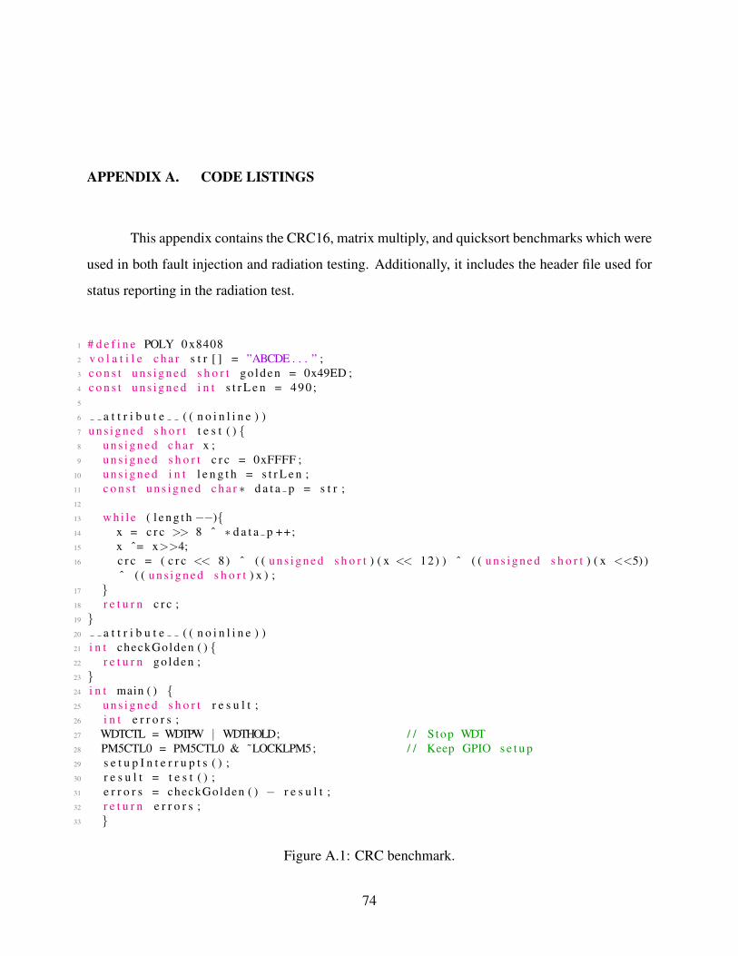
APPENDIX A. CODE LISTINGS
This appendix contains the CRC16, matrix multiply, and quicksort benchmarks which were
used in both fault injection and radiation testing. Additionally, it includes the header file used for
status reporting in the radiation test.
1 # d e f i n e POLY 0 x84082 v o l a t i l e c h a r s t r [ ] = ”ABCDE . . . ” ;3 c o n s t u n s i g n e d s h o r t g o l de n = 0x49ED ;4 c o n s t u n s i g n e d i n t s t r L e n = 490 ;5
6 a t t r i b u t e ( ( n o i n l i n e ) )7 u n s i g n e d s h o r t t e s t ( ) {8 u n s i g n e d c h a r x ;9 u n s i g n e d s h o r t c r c = 0xFFFF ;
10 u n s i g n e d i n t l e n g t h = s t r L e n ;11 c o n s t u n s i g n e d c h a r ∗ d a t a p = s t r ;12
13 w h i l e ( l e n g t h −−){14 x = c r c >> 8 ˆ ∗ d a t a p ++;15 x ˆ= x>>4;16 c r c = ( c r c << 8) ˆ ( ( u n s i g n e d s h o r t ) ( x << 12) ) ˆ ( ( u n s i g n e d s h o r t ) ( x <<5) )
ˆ ( ( u n s i g n e d s h o r t ) x ) ;17 }18 r e t u r n c r c ;19 }20 a t t r i b u t e ( ( n o i n l i n e ) )21 i n t checkGolden ( ) {22 r e t u r n g o l de n ;23 }24 i n t main ( ) {25 u n s i g n e d s h o r t r e s u l t ;26 i n t e r r o r s ;27 WDTCTL = WDTPW | WDTHOLD; / / S top WDT28 PM5CTL0 = PM5CTL0 & ˜LOCKLPM5; / / Keep GPIO s e t u p29 s e t u p I n t e r r u p t s ( ) ;30 r e s u l t = t e s t ( ) ;31 e r r o r s = checkGolden ( ) − r e s u l t ;32 r e t u r n e r r o r s ;33 }
Figure A.1: CRC benchmark.
74

1 # d e f i n e s i d e 92 u n s i g n e d i n t f i r s t m a t r i x [ s i d e ] [ s i d e ] = {3 {4862 ,39548 ,33171 ,8941 ,32884 ,7091 ,35326 ,46445 ,38174} ,4 . . .5 } ;6 u n s i g n e d i n t s e c o n d m a t r i x [ s i d e ] [ s i d e ] = {7 {30692 ,19854 ,7942 ,17293 ,13351 ,14481 ,21634 ,62641 ,43863} ,8 . . .9 } ;
10
11 u n s i g n e d i n t x o r g o l d e n = 46324 ;12 u n s i g n e d i n t r e s u l t s m a t r i x [ s i d e ] [ s i d e ] ;13 vo id m a t r i x m u l t i p l y ( u n s i g n e d i n t f m a t r i x [ ] [ s i d e ] , u n s i g n e d i n t s m a t r i x [ ] [
s i d e ] , u n s i g n e d i n t r m a t r i x [ ] [ s i d e ] ) {14 u n s i g n e d i n t i = 0 ;15 u n s i g n e d i n t j = 0 ;16 u n s i g n e d i n t k = 0 ;17 u n s i g n e d long sum = 0 ;18 f o r ( i = 0 ; i < s i d e ; i ++ ) {19 f o r ( j = 0 ; j < s i d e ; j ++ ) {20 f o r ( k = 0 ; k < s i d e ; k++ )21 sum = sum + f m a t r i x [ i ] [ k ]∗ s m a t r i x [ k ] [ j ] ;22 r m a t r i x [ i ] [ j ] = sum ;23 sum = 0 ;24 }25 }26 }27 a t t r i b u t e ( ( n o i n l i n e ) )28 i n t checkGolden ( ) {29 u n s i g n e d i n t xor = 0 ;30 u n s i g n e d i n t i , j ;31 f o r ( i =0 ; i<s i d e ; i ++)32 f o r ( j = 0 ; j < s i d e ; j ++)33 xor ˆ= r e s u l t s m a t r i x [ i ] [ j ] ;34 r e t u r n ( xor != x o r g o l d e n ) ;35 }36 a t t r i b u t e ( ( n o i n l i n e ) )37 vo id t e s t ( ) {38 m a t r i x m u l t i p l y ( f i r s t m a t r i x , s e c o n d m a t r i x , r e s u l t s m a t r i x ) ;39 }40
41 i n t main ( ) {42 i n t numErrors ;43 WDTCTL = WDTPW | WDTHOLD; / / S top WDT44 PM5CTL0 = PM5CTL0 & ˜LOCKLPM5; / / Keep GPIO s e t u p45 s e t u p I n t e r r u p t s ( ) ; / / Enab le F I J I i n t e r r u p t s46 t e s t ( ) ;47 numErrors = checkGolden ( ) ;48 r e t u r n numErrors ;49 }
Figure A.2: Matrix multiplication benchmark.
75

1 # d e f i n e a r r a y e l e m e n t s 1202 i n t a r r a y [ a r r a y e l e m e n t s ] = {0 x4ac6 , . . . , 0 x86cd } ;3 i n t g o l de n = 8114 ;4
5 / / QS code from h t t p : / / r o s e t t a c o d e . o rg / w ik i / S o r t i n g a l g o r i t h m s / Q u i c k s o r t #C6 vo id q u i c k s o r t ( i n t ∗ A, i n t l e n ) {7 i f ( l e n < 2) r e t u r n ;8 i n t p i v o t = A[ l e n / 2 ] ;9 i n t i , j ;
10 f o r ( i = 0 , j = l e n − 1 ; ; i ++ , j−−) {11 w h i l e (A[ i ] < p i v o t ) i ++;12 w h i l e (A[ j ] > p i v o t ) j−−;13 i f ( i >= j ) b r e a k ;14 i n t temp = A[ i ] ;15 A[ i ] = A[ j ] ;16 A[ j ] = temp ;17 }18 q u i c k s o r t (A, i ) ;19 q u i c k s o r t (A + i , l e n − i ) ;20 }21
22 a t t r i b u t e ( ( n o i n l i n e ) )23 i n t checkGolden ( ) {24 i n t n u m o f e r r o r s = 0 ;25 i n t i ;26 i n t xor = a r r a y [ 0 ] ;27 f o r ( i =1 ; i<a r r a y e l e m e n t s ; i ++) {28 i f ( a r r a y [ i ] < a r r a y [ i −1]) {29 n u m o f e r r o r s ++;30 }31 xor ˆ= a r r a y [ i ] ;32 }33 i f ( xor != g o l den ) n u m o f e r r o r s ++;34 r e t u r n n u m o f e r r o r s ;35 }36
37 a t t r i b u t e ( ( n o i n l i n e ) )38 vo id t e s t ( ) {39 q u i c k s o r t ( a r r a y , a r r a y e l e m e n t s ) ;40 }41
42 i n t main ( ) {43 i n t e r r o r s ;44 WDTCTL = WDTPW | WDTHOLD; / / S top WDT45 PM5CTL0 = PM5CTL0 & ˜LOCKLPM5; / / Keep GPIO s e t u p46 s e t u p I n t e r r u p t s ( ) ;47 t e s t ( ) ;48 e r r o r s = checkGolden ( ) ;49 r e t u r n e r r o r s ;50 }
Figure A.3: Quicksort benchmark.
76

1 # d e f i n e DONE DIR P1DIR2 # d e f i n e ACK DIR P1DIR3 # d e f i n e SEL DIR P1DIR4 # d e f i n e LED DIR P1DIR5 # d e f i n e DONE PORT P1OUT6 # d e f i n e ACK PORT P1IN7 # d e f i n e SEL PORT P1OUT8 # d e f i n e LED PORT P1OUT9 # d e f i n e DONE PIN BIT3
10 # d e f i n e ACK PIN BIT411 # d e f i n e SEL PIN2 BIT512 # d e f i n e SEL PIN1 BIT713 # d e f i n e SEL PIN0 BIT614 # d e f i n e LED PIN BIT015 i n t NO TMR ERROR = 1 ;16 enum t e s t i n g s t a t e s {17 s u c c e s s , / / done p i n 1 00018 b a d v a l u e , / / done p i n 1 00119 t m r d e t e c t a n d s u c c e s s , / /TMR e r r o r t o l e r a t e d 01120 t m r d e t e c t a n d e r r o r } ; / /TMR d e t e c t , b u t b a d v a l u e 11021 vo id wai tForAck ( ) { w h i l e ( ! ( ACK PORT & ACK PIN ) ) ; }22 vo id s e t S t a t u s ( i n t r e s u l t ) {23 s w i t c h ( r e s u l t ) {24 c a s e s u c c e s s : / / 00025 SEL PORT &= ˜ SEL PIN0 ;26 SEL PORT &= ˜ SEL PIN1 ;27 SEL PORT &= ˜ SEL PIN2 ;28 b r e a k ;29 c a s e b a d v a l u e : / / 00130 SEL PORT |= SEL PIN0 ;31 SEL PORT &= ˜ SEL PIN1 ;32 SEL PORT &= ˜ SEL PIN2 ;33 b r e a k ;34 c a s e t m r d e t e c t a n d s u c c e s s : / / 01135 SEL PORT |= SEL PIN0 ;36 SEL PORT |= SEL PIN1 ;37 SEL PORT &= ˜ SEL PIN2 ;38 b r e a k ;39 c a s e t m r d e t e c t a n d e r r o r : / / 11040 SEL PORT &= ˜ SEL PIN0 ;41 SEL PORT |= SEL PIN1 ;42 SEL PORT |= SEL PIN2 ;43 b r e a k ;44 d e f a u l t : / / s h o u l d n o t g e t here , r e p o r t t i m e o u t45 SEL PORT |= SEL PIN0 ;46 SEL PORT |= SEL PIN1 ;47 SEL PORT |= SEL PIN2 ;48 b r e a k ;49 }50 DONE PORT |= DONE PIN ;51 }
Figure A.4: Radiation test supporting header file.
77
Related Documents