Welcome message from author
This document is posted to help you gain knowledge. Please leave a comment to let me know what you think about it! Share it to your friends and learn new things together.
Transcript


Compendium on IPv6 Based Solutions/Architecture/Case Studies for Different Industry Verticals
First Published: August, 2014
Disclaimer
This document is meant for circulation amongst all the stakeholders in the field of ICT. The information contained is mostly compiled from different sources and no claim is being made for being original. Every care has been taken to provide the correct and up to date information along with references thereof. However, neither DoT nor the authors shall be liable for any loss or damage whatsoever, including incidental or consequential loss or damage, arising out of, or in connection with any use of or reliance on the information in this document. In case of any doubt or query, readers are requested to refer to the detailed relevant documents.


Foreword
The Internet has come a long way since it was invented 30 years ago with IPv4 as the backbone Internet Protocol. Now this version of the Internet Protocol (IPv4) has almost run out of free addresses. The broadband revolution that is on the verge of sweeping the country is sure to ride on IPv6 only. IPv6 has many inherent advantages because of which we will see the development of new and innovative applications and services in future.
It is against this backdrop that the Government released the first roadmap ‘National IPv6 Deployment Roadmap version-I’ in July, 2010 to set the policy framework for introduction of IPv6 in the country. The Government also took an important decision to create the ‘India IPv6 Task Force’, which, for the first time in the country, brought together the stakeholders to a common platform for implementation of IPv6 in the country. This Task Force created the momentum required for all concerned to become aware of IPv6 and its importance. Once a certain level of awareness was achieved, the Government followed it up with the ‘National IPv6 Deployment Roadmap version-II’ in March, 2013, which set the targets for smooth transition to IPv6 in the coming years by the different stakeholders as per National Telecom Policy-2012.
Time and again, questions have been raised by different stakeholders about the utility of IPv6, its advantages, how it can be implemented and what are the new applications possible in IPv6. Therefore, this present document is an attempt to showcase the pioneering efforts of some of the organizations in the Government and private sector in the form of practical case studies and applications being implemented by them in various areas like power and energy sector, banking, agriculture, Government and educational networks, industrial automation etc.
I sincerely hope that with this initiative, different stakeholders will be encouraged to adopt IPv6 and its different applications in their organizations for the larger benefit of the economy.
(R M Agarwal)
DDG (NT)

Executive Summary
The Government of India released the first IPv6 policy document, the ‘National IPv6 Deployment Roadmap version-I’, in July, 2010, which laid the foundation for planned IPv6 transition in the country. This was followed by the ‘National IPv6 Deployment Roadmap version-II’ in March, 2013, setting the targets for different stakeholders for planned transition to IPv6 as per National Telecom Policy-2012.
However, different stakeholders have often raised questions regarding the deployment of IPv6 for new and innovative applications. There are many organizations that have made pioneering efforts in this direction by adopting IPv6 in new applications in power and energy sector, banking, agriculture, Government and educational networks, industrial automation etc. These can, therefore, serve as good examples for others. This document is an effort to bring such initiatives together and present them at one place for the benefit of the ecosystem.
Chapters 1, 4, 10 and 12 showcase the initiatives by some of the State Governments in the country namely Madhya Pradesh, Gujarat, Maharashtra and West Bengal in adoption of IPv6 in networks of their State and State Data Centres.
Chapter 2 presents an innovative application of IPv6 in the agriculture sector. The project uses the IPv6 capabilities of wireless sensor networks for getting the information from the palm oil trees and sending the data to back-end system to be analysed.
Chapter 3 focuses on IPv6 adoption by IIT Kanpur, a premier educational institution of India. This chapter presents the methodology adopted by IIT Kanpur for transition of its campus network to IPv6. This work was carried out at IIT, Kanpur under BITCOE (BSNL IIT Kanpur Telecom Centre of Excellence) IPv6 project.
Chapter 5 & 14 present the deployment of IPv6 in facility automation in a building infrastructure thereby leading to intelligent control of the building resources. The Internet architecture used in the projects is based on IPv6 and preserves five essential features of a modern intelligent network - autonomous, distributed, disconnected, inter-domain, and global operation. The project explained in chapter 5 is the ‘GUTP – Green University of Tokyo Project’ implemented in Japan. This project lays the foundation of future intelligent cities. Chapter 14 describes the concept details about how any building can go about planning for intelligent facility control.
Chapter 6 explains the adoption of IPv6 by C-DoT, a premier R&D organization in the country. Chapter 7 gives a case study where, a large private sector bank in India decided to implement IPv6 connectivity to their Internet driven applications like website, online banking portal, payment gateways etc. without impacting existing IPv4 service access.
A chapter 8 enumerates the advantages of implementation of smart grid on IPv6 based infrastructure in the power sector. Chapter 9 showcases the pilot conducted by M/s Reliance Infrastructure Ltd which demonstrates the adoption of IPv6 based networking for all Smart Grid services allowing devices involved to be managed through a single network view.

In the domain of process control and automation, SCADA (Supervisory Control and Data Acquisition) is deeply entrenched. Chapter 11 contributed by NIT Hamirpur provides one such case study where IPv6 based sensors have been used in industrial automation by a steel plant in its SCADA system. Chapter 13 describes the details about how M/s Tata Communications Limited went about deploying IPv6 over their existing IPv4 infrastructure by using a technology called 6VPE.

Acknowledgements
The Internet has become all pervasive in today’s world and is touching the lives of the citizens in one way or the other. There is hardly any sector which has been left untouched by the influence of the Internet. In the backdrop of depletion of free IPv4 addresses, the Government has released two roadmaps ‘National IPv6 Deployment Roadmap Version-I and Version-II’ for systematic transition to IPv6 in the country. In the aftermath, as a next step forward, this document presents a bouquet of case studies regarding IPv6 transition across various sectors to facilitate the ecosystem in its journey towards IPv6.
We are thankful to Shri Rakesh Garg, Secretary (T), Shri A K Purwar, Member (T), Shri Ram Yagya, Member (Services) and Ms. Annie Moraes, Member (Finance) for their valuable guidance and encouragement. Without their guidance and support, formulation of this document would not have been possible.
We take this opportunity to show our thanks to Shri A K Mittal, Sr.DDG TEC, Sh. Hari Ranjan Rao, Secretary (IT), MP State Government, Sh. S. J. Haider, Secretary, Department of Science & Technology, Gujarat State Government, Sh. Rajesh Aggarwal, Secretary (IT), Maharashtra State Government, Sh. Srabani Banerjee, Secretary (IT), West Bengal State Government officers and Prof. Dr. Sureswaran Ramadass, NAv6 Malaysia for their contribution in the formulation of this document.
We would like to express our special thanks to all the officers and staff of NT Cell, DoT for their support during the entire period of preparation of this document.We would also like to sincerely thank everyone who has contributed directly or indirectly during the preparation of this document.
Drafting Committee

The following contributors have provided write-ups for this compendium:
Contributors
Sl. No Name Organisation
1 Sh. Avinash Lawania MP State Government
2 Sh. Gopinath NAv6 Malaysia
3 Sh. Navpreet Singh IIT, Kanpur
4 Smt. Neeta Shah Gujarat State Government
5 Sh. Hiroshi Esaki University of Tokyo, Japan
6 Sh. Aurindam Bhattacharya C-DOT
7 Sh. Yogesh Padharia M/s Softcell Technologies Ltd.
8 Sh. C N Sai Sravanan NT Unit, DoT, Puducherry
9 Sh. Ajoy Rajani M/s Reliance Infrastructure Ltd.
10 Sh. Laxmikanth Tripathi Maharashtra State Government
11 Sh. Kumar Sambhav Pandey NIT, Hamirpur
12 Sh. Abhishek Roy West Bengal State Government
13 Sh. Naveen Dhar M/s Tata Communications Ltd.
14 Sh. Sudeep Kumar NTIPRIT, DoT
The compendium has been finalised and drafted by the drafting committee consisting of the following:
S. No. Name Designation Organisation
1 Sh. R.M. Agarwal DDG (NT) DoT, New Delhi
2 Sh. B.K. Nath Director (TERM) DoT, Shimla
3 Sh. N Ram Director (NT-I) DoT, New Delhi
4 Sh. Manish K. Agarwal Director (NT-II) DoT, New Delhi
5 Sh. Praveen Mishra Addl. Director ERNET, New Delhi
The efforts and the contribution of Shri Sh. S K Madhukar, ADG (NT), DoT are special in the formulation and finalisation of this document.


Contents
Chapter Topics Page No.
1 IPv6 Transition in Madhya Pradesh State Government 1
2 Internet of Things (IoT) for Agriculture 14
3 Transition to IPv6 : A Case Study for IIT Kanpur 18
4 IPv6 Roadmap for Government of Gujarat 24
5 Smart City Design Based on Internet Architecture Framework 28
6 IPv6 Transition in C-DOT. 41
7 Adoption of IPv6 by One of India’s Largest Private Sector Bank 46
8 Smart Grid : Powered by IPv6 50
9 A Pilot Project on 6LoWPAN for Last Mile Connectivity for AMI 59
10 Transition to the Future : IPv6 in Government of Maharashtra 68
11 Methodology of Migrating SCADA over IPv4 to IPv6: Case Study of an Integrated Steel Plant 74
12 Success Story in Deployment of IPv6 in West Bengal State Data Centre 79
13 6VPE implementation in TCL 84
14 Smart Building: A Concept 89
Annexures 96
Glossary 100

1
1. Introduction
Internet, essentially identified as the driver for socio-economic growth of the country, has reached a point of inflection with the exhaustion of IPv4 address space. This requires newer addresses to sustain and scale further for maintaining business continuity and growth. IPv6 with its near infinite address space (2^128) not only addresses this scaling issue but also offers enhanced features including auto-configuration, integrated security ,greater mobility, multi-homing and superior reliability enriching Internet experience for the users while enabling innovations for developing enhanced citizen centric services.
India as a country is among the top 3 consumers of Internet with the Government of India being one of the largest users of Information Technology products and services in the country. With a major thrust towards e-governance over the last few years most of the applications and services of the Government are now made available for online access through Internet. It is this Internet presence of the Government networks, applications and services whose availability and scalability needs to be ensured as the transition from IPv4 to IPv6 is undertaken.
With intent to ensure seamless IPv6 transition across Government networks, Department of Telecommunications (DoT) has issued guidelines and mandates through its National IPv6 Deployment Roadmap version-I and II documents for State and Central Governments to achieve complete IPv6 transition (dual stack) by 2017.
The State Government of MP, through Madhya Pradesh State Electronics Development Corporation Ltd. (MPSEDC), has taken a lead on this important initiative to transition the entire State IT network infrastructure and services to IPv6 within the defined timelines. With a view to address the need of growing ICT requirements of the State towards providing impetus to its socio-economic growth, the State Government has taken major steps for proliferation of Internet. Accordingly, the State Government of Madhya Pradesh has appointed MPSEDC as the nodal agency for State IPv6 transition.
MPSEDC intends to get an audit of various IT infrastructures of various organisations under State Government of MP to assess their IPv6 readiness and get a consolidated view of IT infrastructure of the State unit organizations and capture below details:
• Existing Inventory (hardware , software and applications)
• IPv6 readiness status for hardware , software and applications
• IPv6 transition architecture blueprint for each organization
• Develop plan for IPv6 pilot
• Hardware and software upgrade cost estimate with specifi cations for implementations.
I. IPv6 Transition in Madhya Pradesh State Government

2
Few of the direct advantages of IPv6 rollout in the State are as listed below:
• IPv6 deployment will enable MP State Government to build high performance scalable networks and services for proliferation of e-governance services which will further simplify the life of its citizens.
• IPv6 with its ability to offer larger address space will enable acceleration of broadband penetration in the State.
• It will further the initiative on improving both the quality and delivery of education and healthcare across State.
• IPv6 implementation will help rollout services for bridging the rural urban digital divide in the State and create a platform for inclusive growth.
• Foster an environment for introduction and penetration of new services on HSI/3G/4G/Cloud/Cable Digitization for all.
• Increases economic activity leading to jobs creation in urban and rural areas of the State.
• Establish technology thought leadership through deployment of Next Generation Internet Protocol -IPv6.
It is on this basis that MPSEDC has appointed M/s Sixmatrix as consultant for providing end to end consulting on IPv6 readiness and helping design a detailed IPv6 transition blueprint for the State infrastructure. The project scope entails conducting detailed assessment of its 161 units comprising of State offices, PSUs, SWANS, SDC etc. and preparing a comprehensive transition blueprint for these organizations.
2. Objectives
The objective of this consulting process is to provide a detailed account of the following:
• IPv6 Discovery: Collecting information on all State infrastructure including its network, applications and services and prepare assessment and planning report.
• IPv6 Assessment : Detailed assessment of information collected in the discovery process to determine the IPv6 readiness and identify the gaps.
• IPv6 Planning and Design: Designing a comprehensive transition blue print providing detailed solution and a step based plan for integration of IPv6 in to the existing infrastructure and rolling out of new services on IPv6.The plan and design will also identify on budgetary requirements for the transition.
• IPv6 Test Plan: Define a detailed test plan as per the suggested transition blueprint for individual organizations to test the final State network, application and services in a restricted lab environment before deploying in the production network.
• IPv6 Implementation RFP: Define the detailed scope of implementation with required deliverables, procurement, roll out plan with the technical and financial eligibility defined for identifying and short listing of the right implementation agency for carrying out the deployment.

3
3. Methodology & Approach
A phased approach was adopted for the State of Madhya Pradesh which includes proven methodologies, architecture, and best practice guidelines based on a detailed oriented and measurable approach as below:
A. Organisation Categorisation: The entire State organizations list has been categorized for prioritisation based on organization size, footprint, network size, data centre availability, type of applications and criticality of services. Accordingly the organizations have been categorized as below:
Organization Category
Criteria
A+ 1. Network footprint of > 100 nodes2. Own network through SWAN or operator leased lines3. Own Data Center4. Own critical applications : DNS, DHCP, Radius, Payment
Gateway
A 1. Network footprint of 50-100 Nodes2. Own network through SWAN or operator leased lines3. Own Data Center or hosted in SDC4. Own applications
B 1. Network footprint <25 nodes2. Network through operator leased lines3. No Data Center, hosting at SDC or NIC4. Own applications and services
C 1. Network footprint of < 10 nodes2. No network, only single uplink connectivity through leased
line or broadband.3. No Data Center, hosting at SDC or NIC4. No applications owned.
B. Organisation Summary: The list of organisation summary is as under:
A+ A B C New Total
12 7 30 51 61 161

4
C. IPv6 Project Schedule and Timelines: The schedule & timelines are as under:
S.no Project M1 M2 M3 M4 M5 M6
1. Initiate Project
2. Plan the Project
3. Execute & Control
3.1 IPv6 Discovery
3.2 IPv6 Assessment
3.3 IPv6 Transition Plan
3.4 IPv6 Test Plan
3.5 IPv6 Implementation RFP
3.6 IPv6 Knowledge Transfer
4. Project Signoff & Handover
D. IPv6 Discovery Methodology: IPv6 discovery workshops were conducted with organizations technical team, business team and executive stakeholders to discuss techno-commercial requirements and challenges in adopting IPv6. During the workshop, discussion focused on specific areas to start gathering organizations design requirements along with leading practices of architecture and technical design. The activities included:
� The Discovery and Assessment sheet for data collection on inventory, networks, IP address, applications and services to assess the gaps and readiness on IPv6 was shared.
� Comprehensive workshops were held individually with all the A+ and A category organization stakeholders to explain the process for filling up the sheet to ensure the right information gets captured.
� The workshops for B&C category organizations were held commonly at State IT Center. These workshops were held for 6-7 organizations at a time and multiple such workshops were held on a continuous basis to cover up all the individual organizations.
� Extensive follow up sessions were conducted for helping organizations on completing the sheets
� Extensive meetings were held with organization system integrators and consultants to capture the required information on discovery and assessment.
The Discovery and Assessment sheet referred above captured organization wise information on following points:
� Network Architectures and Diagrams

5
� Network Profiles
� Application and Service Profile
� IP Addressing Plan
� Transport Network Details
� Data Center Network Details
� Services and Applications Details
� Security Details
� OSS/BSS Details
� Network Element Details
� Subscriber End Device details
� Procurement plans
E. IPv6 Assessment Methodology and Activities: The captured information was used for IPv6 assessment to build a consolidated business and technical requirement document for IPv6 transition and also identify current state of IPv6 device and applications readiness in network. On finalization of customer requirements document, the individual organization’s infrastructure was analysed to determine the current state of IPv6 readiness for network devices, applications and services. The following readiness assessment activities were conducted:
� Inventory Gathering: Gather list of devices and IPv6 features/functionality requirements.
� Conduct IPv6 device readiness assessment for network devices, application and services.
� Device readiness assessment : Determine current IPv6 capability , IPv6 capable with software upgrade , IPv6 capable with hardware upgrade, EoS / EoL devices that do not have IPv6 roadmap.
The following readiness assessment deliverables were completed:
� IPv6 Gap Analysis and Readiness assessment report including:
• IPv6 Readiness for Network Devices e.g. Routers, Switches, Firewall, IPS etc.
• IPv6 Readiness for Applications e.g. Windows, Linux, SUN etc.
• IPv6 Readiness for Services e.g. WWW, DNS, DHCP, Email, VPN etc.
� Upgrade plan for network, application and services including the software and hardware upgrade required to support IPv6.

6
F. IPv6 Plan & Design Methodology and Activities: IPv6 plan and design phase is aimed at developing an architecture blueprint and defining a phase-wise transition plan for organizations. Outcome of this exercise is to create high level architecture blueprint. The plan and design activities included:
� Review existing IPv6 network architecture strategy and designs.
� Design workshop with key stake holders.
� Develop high level blueprint.
� Collect detailed information about the existing network infrastructure , application and services.
� Create detailed blueprint document which includes design and configuration templates.
� Provide guidance and recommendations on tool usage such as traffic generators, simulators, scripting and data collection along with lab design support and management.
� Educate appropriate staff and personnel on IPv6 network architecture design and configuration.
The plan and design deliverables completed included:
� IPv6 Architecture Blueprint including :
• IPv6 Network Transition Architecture
• IPv6 Routing Architecture
• IPv6 Addressing Plan
• IPv6 Security Architecture
� IPv6 Low level design.
� IPv6 Best Practices Recommendations.
4. Challenges & Mitigations
The table below describes the challenges faced and their mitigations:
S. No. Challenges Mitigation
1 Lack of Awareness and Agreement
• Most organisations were not aware of why IPv6 should be prioritized.
• Saw it as largely a technology challenge that IT will solve
• Did not see its implication in Governance and Service Improvement
Group and individual workshops held to create awareness and get agreement.

7
2 Reluctance to share information or information not available
• Discovery is the most important phase as the quality of data determines the quality of assessment and transition.
• Reluctance to share data with an external team
• The data was often not accurate / available.
• Did not allow usage of auto-discovery tool
Group and individual workshops held to create awareness and get agreement.
3 Data not available with local team
• The IT services are managed centrally by NIC that manages the web presence and other services.
• Saw it as largely a technology challenge that IT will solve
• Did not see its implication in governance and service improvement
Group and individual workshops held to create awareness and get agreement
4 Inventory of local business applications
• There are many custom built applications that may be residing in servers and desktops
• The teams do not have accurate inventory of such applications as they are not the owners.
Have rollback plans available if problem still appears during transition.
5 Scripts that have IPv4 address
• IP address in logs, databases, trace routes etc.
Need to have rollback plans available if problem comes after transition.
6 Knowledge and expertise in IPv6
• Teams need to be able to accommodate new functionality and fi ne tune performance in case of changes in topology.
• Expertise needs to be built in the teams to handle this.
Providing the right training across various organization levels and certifying resources on IPv6 skillset.

8
7 Generic Issues
• We have to maintain parallel logical infrastructures – both v4 and v6. If there is a bug in the v6 software, it will bring the hardware down, and the service will go down.
• Bad upstream IPv6 connectivity can lead to long time outs in applications.
• Every time one adds a new host, one will have to give it an IPv6 and an IPv4 address. The IPv4 addresses, even if private, may run out.
• Uncontrolled connectivity may be a security issue.
Testing, re-calibrating, applying knowledge to resolve such issues.
5. State Level Discovery Summary
A. Network Devices Discovery Summary: The overall discovery activity identified the installed base of network devices and applications. Of the total installed base of network devices, the top 8 organizations in A+ and A category as shown below account for more than 95% of the State infrastructure:
� State Wide Area Network (SWAN)
� State Data Center (SDC)
� MPSEB (Madhya Pradesh State Electricity Board)
� Madhya Pradesh Excise Department
� Commercial Tax
� MP Forest Department
� High Court
� Treasury

9
The State infrastructure consists of mix of IP network devices such as routers, switches, firewalls, load balancers and IPS as shown below:
B. State Wide Area Network (SWAN): MP SWAN connectivity follows a hierarchical topology as below:

10
C. State Data Centre: As shown below, State Data Center network follows a layered structure consisting of :
� Core
� Aggregation
� Access
D. Application Discovery Summary: The applications are primarily categorized across 2 levels as under:
� Infrastructure Applications: DNS, DHCP, AAA, HTTP, EMAIL, OSS/BSS
� In-house Applications
E. Services Discovery Summary: The State services are primarily categorized as under:
� Data Services
� Voice Services
� Video Services
� Data Center Services
6. State Level Assessment Summary
A thorough assessment was conducted on the information collected in the discovery phase to determine the IPv6 readiness of the State infrastructure.

11
A. Network Devices Assessment Summary:
B. Applications Assessment Summary:

12
7. Implementation Plan
It is expected to complete the State level transition plan as per DoT timelines. The implementation timeline is expected to be completed in 2014 for critical State infrastructures like SWAN and SDC. The other State infrastructures are expected to undertake implementation in a phased manner and are expected to complete it well before the 2017 timelines.
8. IPv6 Best Practices & Recommendations
The summary of best practices & recommendations are as below:
� IPv6 Readiness
• Infrastructure should be upgraded to support IPv6 as per assessment report
• Proxy server needs to be upgraded to support enhanced IPv6 functionality
� IPv6 Address Allocation
• Recommended to have Provider Independent(PI) Global Unicast address space(/32 or larger) for SWAN/SDC network.
• Should subnet to /48 for individual organizations assignment
� IPv6 Address Provisioning
• All infrastructure devices(Routers/switches) should be statically configured for IPv6 address

13
• All servers(Web/AAA etc) should be configured with a static IPv6 address
• All Hosts should have IPv6 Auto-config provisioning of address in addition to IPv4 address
� IPv6 Routing
• All infrastructure devices(Routers/switches) should be run OSPFv3 in addition to OSPFv2 to support IPv6 routing
• Should run BGP+ to advertise/receive BGP routes from upstream ISP in dual homing topology
� IPv6 Application/Services
• Web Application to be transition to dual-stack
• DNS should have AAAA record for Web server address resolution
• AAA , Video , Voice and NMS should also transition to dual-stack
� IPv6 Security
• Selectively filter ICMP (RFC 4890)
• Block Type 0 Routing Header at the edge
• Implement RFC 2827-like filtering
• Deny IPv6 fragments destined to an internetworking device
• Use IPsec to secure routing protocols
14
1. Introduction
Internet of Things (IoT) has seen rapid advances both in technological aspects and implementation in various sectors. The Internet of Things allows people and things to be connected Anytime, Anyplace, with Anything and Anyone, ideally using Any Path/Network and Any Service. This is achieved with the elements of Convergence, Content, Collection (Repositories), Computing, Communication and Connectivity in the context where there is seamless interconnection between people and things and/or between things and things.
IoT is currently being deployed in various sectors such as Agriculture, Aquaculture, Home and Building Automation, Industries and many more. One simple IoT application is for Oil Palm Plantation specifically for pollination of the oil palm trees. Currently, the pollination in oil palm plantation is conducted manually. The automated process using IoT would enable better efficiency of end-to-end system.
2. Technology
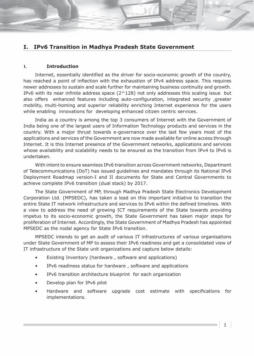
The ecosystem of Internet of Things is given in the figure below.
II. Internet of Things (IoT) for Agriculture
MIMOS Berhad, Malaysia
Figure: End-to-end Communication in Internet of Things
Sensors and other end devices, which produce and consume data or information (prosumers), will provide data to be processed at the back-end system. Gateway is crucial in the implementation as it interfaces between the sensor networks to the Internet. End-to-end communication should be common and it has been agreed that IPv6 would be used as the main communication protocol. This however has many challenges. One of the challenges is the inability of end devices to be configured with the protocol stack.
There are few entities in the implementation of the wireless sensor network Smart Agriculture based on the ecosystem given in figure above:

15
� Wireless Sensor Nodes (WSN) – These nodes have two components: a sensor tip used to check the temperature and a communication module that transfer data collected to the gateway.
� Gateway – This device is used to collect data from WSN nodes and sends it to a Central Management System.
� Central Management System – It consists of data logging and intelligent pollination system.
3. Need/RequirementThe specifi c case for palm oil plantation is due to the operational issues for pollination.
Existing manual monitoring is labour intensive. Labourer has to climb up a tree to check if the temperature is right for it to be pollinated. The required solution involved getting the information from the palm oil trees and sending the data to back-end system to be analysed.
4. Planning
In the phase-I of the implementation, the WSN nodes are configured to use ZigBee proprietary protocol and the data is transmitted over GPRS to the collector. Due to the limitation of ZigBee protocol, 6LoWPAN stack is planned to be used in phase-II implementation. This enables the WSN nodes to be addressable using IPv6 address and can be reachable from external network through the Gateway. The figure below shows the implementation of the system. The wireless sensor network operates on 2.4GHz frequency and one-hop distance is about 100 metres. This distance varies with other implementations as it depends on the hardware being used and the environmental factors. In the initial implementation the data collected twice a day is transmitted to back-end system using GPRS network. At the back-end system, data is collected and analysed for further action.
Figure: Smart Agriculture System (©2013 MIMOS Berhad)

16
5. Practical Implementation
This system has been implemented in few selected palm oil plantation in Malaysia. It can also be extended to other agriculture sectors but further studies are required so that knowledge on the said sector can be retrieved and applied appropriately. One of the sectors that require constant monitoring is the aquaculture. One of the problems in this sector is the knowledge of the condition of the pond or fish breeding area. This system can also be implemented in office to control the air-conditioning, lights and detect movement of goods and people.
6. Execution
The data provided by sensors need to be transformed into information and knowledge. This is done using semantic technology and data mining in the back-end system. This is called sensing as a service. In this method, IoT Gateway has to extend WSN network connectivity to external network. There is a common IoT architecture which was developed to handle this (MIMOS IP). Since most of the sensors are not addressable, a communication method between the sensors and the external network has to be established using the IoT Gateway. One of the methods is using virtual IPv6 addresses to the sensor nodes (MIMOS IP). This can create a new business model which is to provide virtual addresses to non-IP devices.
IPv6 is used in the implementation because of the following factors:
� Identification – Nodes can be identified using common addressing system irrespective of the hard profile being used
� Scalable – Since IPv6 provides unimaginable amount of address space, it can be used to cater any number of devices. IPv6 is being used as a standard communication in IoT.
� Communication – Sensor nodes can now communicate effectively with other external IP devices. Thus 2-way communication can be established.
� IP functionalities – Existing IP functionalities can now be extended to low power devices such as ICMP messages, HTTP over IP, mobility etc.
The phase-II implementation which is using IPv6 as the communication protocol is shown in figure below:
Figure: Implementation using 6LoWPAN
17
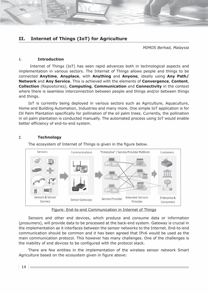
As shown in figure above, the sensor nodes would be given a specific prefix. The nodes can be configured with full IPv6 address or given a unique address at the gateway. Information at the server can be accessed by external clients either using a web browser or by directly communicating with the sensor as shown in figure below:
The cost involved is based on the scope of implementation that includes area size, number of sensors and gateways required, etc.
7. Benefits & Key Insights
Some of the benefits of using smart agriculture system for oil palm pollination are as follows:
� To be able to trigger anthesis period within 3-day window.
� To increase yield.
� To increase productivity.
� Possible reduction of labour dependency.
� To be able to directly communicate with the sensor nodes to get real time data using IPv6 network
8. Conclusion
IoT ecosystem can be deployed in various sectors provided that the end-to-end devices and solutions are properly configured. IPv6 is the key for deployment of IoT as it provides large pool of addresses to be configured to the end devices such as sensors.
Figure: Interfaces to Read and Display Data(©2013 MIMOS Berhad)

18
Abstract
Due to an unprecedented growth of Internet and Internet based services in the last decade, existing network protocols have started showing their limitations. One of the most important concerns is the address space offered by the Internet Protocol (IP). Due to uneven distribution of IP addresses, large demand of addresses by newer applications and limited hosts that the current version of IP (IPv4) can accommodate, there is a need to change the IP addressing scheme. This article presents the methodology adopted by IIT Kanpur for transition to IPv6. This work was carried out at Indian Institute of Technology, Kanpur under BITCOE (BSNL IIT Kanpur Telecom Centre of Excellence) IPv6 project.
1. Introduction
IIT Kanpur is a premium educational institute of India. It has a large network with more than 18000 nodes and Internet bandwidth of 3 Gbps. In view of the requirement to migrate to IPv6, a transition methodology was developed under BITCOE in collaboration with BSNL (Bharat Sanchar Nigam Ltd.), one of the largest service providers in India.
It will take many years for IPv6 to completely replace IPv4. Till then, a slow transition from IPv4 to IPv6 will happen. During this period, both IPv4 and IPv6 will coexist and the networks and hosts may support only IPv4, both IPv4 and IPv6 and only IPv6.
The following three techniques have been proposed for the transition [4]:
� Dual-Stack Hosts and Networks
� Tunneling IPv6 via IPv4
� IPv4 - IPv6 Translators
The technique adopted for IPv4 to IPv6 transition at IIT Kanpur uses Dual Stacking. This allows all the end hosts and intermediate network devices (like routers, switches, modems etc.) to have both IPv4 and IPv6 addresses and protocol stack. If both the end stations support IPv6, they can communicate using IPv6; otherwise they will communicate using IPv4. This will allow both IPv4 and IPv6 to coexist and slow transition from IPv4 to IPv6 can happen.
2. Network Architecture
The figure below shows the network architecture of IIT Kanpur network at the time of IPv6 implementation:
III. Transition to IPv6: A Case Study for IIT Kanpur
Navpreet Singh, IIT Kanpur

19
All the active components were from Cisco. The details of the models and their IOS version, prior to the migration, are given in the following table:
S.No. Type Model IOS Version Remarks
1. Backbone Switch Cisco 6509 12.2(17r)S2 IPv6 support available
2. Data Centre Switch
Cisco 6509 12.2(17r)SX5 IPv6 support available
3. Distribution Switch
Cisco 3750 12.2(25r)SE1 IPv6 support not available
4. Access Switch Cisco 2960 12.2(25r)SEE1 IPv6 support available
5. UTM (Unifi ed Threat Management)
Fortigate 3600A
IPv6 support not available in the loaded software version
6. Gateway Router Cisco 7206 12.3(4r)T3 IPv6 support available
3. Transition Methodology
Any organization looking for a transition to IPv6 needs to follow a planned transition so that both IPv4 and IPv6 can coexist and in the long run, IPv4 can be phased out.
Under BITCOE (BSNL IIT Kanpur Telecom Centre of Excellence), a project on Implementation of IPv6 in BSNL NIB Network [8] was undertaken in 2008. As a part of this project, IPv6 Internet connectivity was provided by BSNL (Bharat Sanchar Nigam Limited). BSNL is one of the largest Internet and voice service providers in the country. Its backbone network, NIB (National Internet Backbone), is an IPv4 network. However for providing IPv6 services to IIT Kanpur, they had upgraded a part of their network to support IPv6.
Figure: Network Architecture of IIT Kanpur

20
In order to migrate to IPv6, IIT Kanpur made a strategic plan for the transition ensuring that the services do not get disturbed and the financial implications are minimized. The steps proposed for the transition were:
1. Check IPv6 Compliance: Study the existing network and verify that all the equipment installed supports IPv6. Recommend upgrade of the equipment which does not support IPv6. The upgrade could be in terms of software upgrade or hardware upgrade/replacement. All future equipment purchase must ensure that the equipment is IPv6 compatible.
2. Plan IPv6 Addressing: Take IPv6 addresses from the Regional Internet Registry (APNIC [7] in case of India) or upstream Internet provider. Make IPv6 Address allocation policy and plan IPv6 addressing for the entire network.
3. Enable IPv6 Routing: Enable IPv6 routing in the entire network. For organization LANs, this would require IPv6 address configuration in all layer 3 switches and routers and enable static/dynamic routing inside the network.
4. Setup IPv6 Application Servers: Upgrade the Domain Name Servers (DNS) to support IPv6 address resolution. Other servers like web servers, mail servers, network management servers etc. can also be upgraded to support IPv6.
5. Enable IPv6 Peering: Enable BGP (Border Gateway Protocol) routing for IPv6 peering with upstream Internet provider to provide Internet access over IPv6.
6. Migrate Services on IPv6: Test various services like Internet access, Email, VoIP, IPTV etc. on IPv6 and migrate the services to support both IPv6 and IPv4.
4. Implementation and Result
IIT Kanpur has been at the fore-front of experimenting, testing and using IPv6. Following implementations step were followed for migration to IPv6:
1. The equipment compliance check revealed that the backbone switch, data centre switch and access switches are IPv6 compliant. The IOS of the Distribution switch needed to be upgraded. The Fortigate UTM did not support full IPv6 functionality.
2. 2001:DF0:92:::/48 address range has been allocated by APNIC to IIT Kanpur.
3. The Backbone Switch configuration was modified to configure IPv6 addresses for all VLANs. The clients obtain the IP address using autoconfiguration. A sample of the relevant configuration of the backbone switch is:
!
ipv6 unicast-routing
!
interface Vlan11
description (FB9/1) HALL-1
ip address 172.24.7.254 255.255.248.0

21
ip policy route-map Hostel_Network
ipv6 address 2001:DF0:92:11::1/64
!
interface Vlan12
description (FB9/2) HALL-2
ip address 172.24.15.254 255.255.248.0
ip policy route-map Hostel_Network
ipv6 address 2001:DF0:92:12::1/64
ipv6 enable
!
ipv6 route ::/0 2001:DF0:92::1
!
4. The IOS of the Distribution Switches were upgraded to support IPv6.
5. Since The UTM device could not be upgraded due to financial implications, a Cisco 7206 Internet Gateway Router was used to provide Internet connectivity over IPv6 using BGP [5]. The relevant configuration of the Gateway Router is:
!
interface GigabitEthernet0/1
description Connected to IITK LAN
ip address 203.197.196.18 255.255.255.224 secondary
ip address 172.31.1.254 255.255.0.0
ip nat inside
mit exceed-action drop
load-interval 30
duplex auto
speed auto
media-type rj45
negotiation auto
ipv6 address 2001:DF0:92::1/64
ipv6 enable
!
interface GigabitEthernet0/2
description ISP IPv6 Connectivity

22
ip address 59.144.72.85 255.255.255.248
ip access-group 120 in
ip access-group 121 out
ip nat outside
load-interval 30
duplex auto
speed auto
media-type rj45
negotiation auto
ipv6 address 2404:A800:2:D::2/64
ipv6 enable
!
router bgp 55479
synchronization
bgp log-neighbor-changes
redistribute static
neighbor 2404:A800:2:D::1 remote-as 9498
no auto-summary
!
address-family ipv6
neighbor 2404:A800:2:D::1 activate
network 2001:DF0:92::/48
exit-address-family
!
ipv6 route ::/0 2404:A800:2:D::1
!
All the users were able to seamlessly use the Internet and other network services using both IPv4 and IPv6.
5. Conclusion
In view of the explosive growth of Internet and convergence of various voice, video and data services over IP (all IP networks), there is a clear need to migrate to the new Internet Protocol. The change-over has challenges which need to be addressed. This article has highlighted the need to move to IPv6 and presented a strategy to achieve this through a slow

23
and very cost effective transition methodology rather that a quick change-over. Although the current trend indicates that IPv6 deployment is now more out of need than just research interest, it is to be seen how and when the Internet community fully adopts IPv6.
6. References
[1] IETF IPv6 Working Group:http://www.ietf.org/html.charters/ipv6-charter.html
[2] IPv6 Forum: http://www.ipv6forum.com
[3] IPv6 Forum India: http://www.ipv6forum.in
[4] IPv6 Information: http://www.ipv6.com
[5] BGP Mon: http://www.bgpmon.net
[6] http://asert.arbornetworks.com/2009/09/who-put-the-ipv6-in-my-internet/
[7] APNIC: http://www.apnic.net
[8] BITCOE IPv6 Project: http://bitcoeipv6.iitk.ac.in

24
1. Introduction
6-June-2012, marked the launch of IPv6 worldwide; this was the day when the world stepped back a moment to take note of the growing significance and vitality of IPv6. By September-2012, the Regional Internet Registries of Asia Pacific (APNIC- Asia Pacific Network Information Centre) and the Regional Internet Registry of Europe (RIPENCC- Réseaux IP Européens Network Coordination Centre) had already run out of allocatable IPv4 Addresses. This marked a paradigm shift and accelerated the IPv6 adoption process. In India, many ISPs (Internet Service Provider), MNCs (Multi National Corporations), PSUs (Public Sector Units) and Government Organizations have made great in-roads in the IPv6 adoption. This paper focuses on the IPv6 adoption roadmap of the Government of Gujarat, entailing a wide range of challenges and strategies adopted by Government of Gujarat to realize the IPv6 implementation.
2. IPv6 in Gujarat – Humble Beginnings
The IPv6 implementation drive in India was mooted by the Department of Telecommunications (DoT), Government of India. DoT organized IPv6 awareness sessions & workshops for the State Government’s officers. This impetus provided by DoT in the initial stages helped Government of Gujarat to come out with an IPv6 roadmap.
3. The Transition Process
IV. IPv6 Roadmap for Government of Gujarat
a Identification of Nodal Officers: The implementation of any new project/ innovation requires a strong team of committed individuals with an ability to provide leadership and lead from the front. To this effect, as a first step towards the IPv6 transition strategy, the Department of Science & Technology (DST) requested all the departments of the Government

25
of Gujarat to depute one department level nodal officer to interact with DST and take forward the mandate of IPv6 implementation at their department level. All the departments were very active and immediately responded to the clarion call issued by DST for IPv6. Once the department level nodal officers were identified, then DST formed the State Level IPv6 Implementation Committee headed by the State nodal officer -Director, e-governance, Gujarat Informatics Limited.
b. Awareness & Training: After the formation of the State Level IPv6 Implementation Committee, the DST planned for the awareness and training of all nodal officers on IPv6. Awareness trainings were organized with resource personnel from Bharat Sanchar Nigam Limited (BSNL) and CISCO Ltd. These training sessions enabled the participants to gain a first-hand knowledge of what IPv6 actually means and what is the pressing need for transitioning to IPv6. The sessions were inquisitive & interactive and the participants came up with a wide plethora of queries, which were clarified by the resource personnel. After the awareness training on IPv6, the nodal officers apprised their respective departmental heads and CIOs (Chief Information Officers) regarding the importance of IPv6 transition and the active role to be played by each Government department.
c. Readiness Assessment: So now we have identified the nodal officers and sensitized them on the IPv6 transition process. As the next step we carried out a ‘Current State Assessment’ of all critical IT infrastructure of Government of Gujarat with respect to their compatibility with IPv6. This assessment is a very crucial factor in deciding on the IPv6 transition roadmap. The state of the current IT infrastructure and its compliance with IPv6 was checked during this exercise. The exercise was carried out at the following 3 levels :
• State Data Centre (SDC)
• Gujarat State Wide Area Network (GSWAN)
• IT Infrastructure at Department Level
The figure below shows the overall picture we arrived after the assessment.
Figure: Percentage of IPv6 Compliance

26
The IPv6 compatibility levels were quite high at the SDC level, as most of the IT equipments were procured in the past 2-3 years. But the IPv6 compatibility at the GSWAN level and the individual department level was found to be lagging behind. Based on the learnings from this assessment exercise, we planned our IPv6 transition in 3 phases as under:
d. Upgradation to IPv6 Compatible Devices: At the end of the IPv6 readiness assessment exercise we were able to get an overall picture on where Gujarat’s IT Infrastructure stands vis-à-vis the IPv6 compatibility and transition readiness. Among the list of non-compatible devices, we found that around 35-40% of them can be made IPv6 compatible just by upgrading the firmware, the remaining devices have to be physically upgraded either by installing an add-on card or by replacing it with a new device. This upgradation process is currently underway. We have also incorporated in all our RFP (Request For Proposals) and purchase tenders, the requirement of IPv6 compatible devices as a mandatory clause. This has ensured that all our future IT procurements will only be IPv6 compatible devices.
e. Implementation Plan: The implementation plan has been finalized and all the departmental nodal officers have been taken into confidence in arriving at this implementation plan. As a part of the plan, the migration process will be carried out in dual stack mode, where both IPv4 and IPv6 network addresses will be operational at the same time. This will ensure that both IPv6 users and IPv4 users will be able to access all applications / services / network of Government of Gujarat in an un-hindered manner.
Figure: Phases of IPv6 Transition

27
f. Plan Roll Out:
Figure: IPv6 Transition Time Lines
The roll-out of the proposed IPv6 transition plan will only be possible with the un-flinching support of all stakeholders. To this extent Government of Gujarat has already made great in-roads. All departments were already given appropriate awareness & training on IPv6 and they are sensitized on this transition plan. Moreover, our IT vendors, have also risen up to the occasion and committed their full-support for this transition exercise. As envisaged in the plan, the transition will be carried out in phases with dual stack in place. Also we will carry out pilot roll-out for applications/services before commencing on a full-fledged roll-out. The challenges are many and we have a gargantuan task to pull-off. Nevertheless, we are prepared, we know what to do, how to do & when to do. So it’s just a matter of time, before Government of Gujarat makes a complete transition to IPv6 and be a role-model for the rest of the nation.

28
1. Introduction
Future Internet will have to contribute to the improvement of efficiency in all the activities developed and deployed on the Earth, i.e., saying smarter city or building. The internet system discussed in the paper is not the global computer network using the IP (Internet Protocol), but is rather a logical architecture of the system applied to the Internet. As discussed in Green ICT business, we need the ubiquitous and globally scaled sensor and actuator networks in order to develop and to deploy the energy aware system. In this paper, the author discusses why the “Internet” is very efficient platform, leading to Smart System. Many networks will adapt the IP technology to contribute to energy saving, to environment preservation and to energy security. However, these networks would be of so-called closed IP network, which is not connected to the global Internet.
For many under-discussing/under-developing “future” networks, even when it would be a closed network, it will be a global network. However, these may be disconnected, i.e., fragmented. So to conduct and to deliver the innovation, the networks should be interconnected with smaller technical and operational difficulties. Also, it has been proven by the existing Internet that building the network by single entity is so/too expensive, but shared by multiple entities may be far cheaper for all entities.
As a background, when we look at large computer systems, including facility networks, there are many systems and networks that adapt the IP (Internet Protocol). However, still, there are many non-IP or closed IP systems, in the real world. And, many networks and systems tend to be fragmented, from the view point of each company’s business strategy. This is serious concern towards the “Smart System” development.
This paper tries to defi ne the objective and goal of the future Internet for smarter city or town. These are –
(i) Avoiding the fragmentation of IP systems and networks,
(ii) Encourage the collaboration among sub-systems that use IP or may not use IP,
(iii) Explore the smart system that delivers the cheaper system development and deployment, while preserving the technical and business innovations.
Also, the experience after the serious earthquake in Japan in 2011 makes us realize the following two business scenarios regarding the smart city and smart building delivery.
(i) Energy saving and improvement of energy efficiency in the power consuming infrastructure, such as buildings or transportation, is important and provides large contribution
(ii) Energy saving, improvement of operational efficiency and energy security system installation against the incidents is equivalent the increase of capacity of power supply.
V. Smart City Design based on Internet Architecture Framework
Hiroshi Esaki, University of Tokyo, Japan

29
2. Deployment of Smart Infrastructure “By-ICT”
This section discusses how the smart infrastructure should be developed and deployed. The following three points should be considered:
(i) “Experienced Design” [1]:
None of us living with the current Internet system may know how the future Internet will be. The future Internet system will be the result of interaction with real society, i.e., technologies will be modified and mutated via the practical feedback from the real operation. In order to adjust with the practical, un-expected and un-forecast-able feedbacks, the initial future Internet system should have technical vagueness and room to be able to be added or to be modified, in the future, as an architecture design principle.
(ii) “Invention is the Mother of Necessity” [2]:
None of us may know how to use new technologies. Also, the new technologies would introduce new functions or services with their native interfaces. Emulating the legacy or existing services with new technologies may not be good for the development of new technologies. New technologies may perform better with their “native” applications or services.
(iii) Federated Networking for the Next Stage of the “Internet”:
Though many networks will adapt the IP technology, these networks would be of so-called closed IP network, which is not connected to the global Internet. For many under-discussing/under-developing “future” networks, even when it would be a closed network, it will be a global network. However, these networks may be disconnected, i.e., fragmented. So to conduct and to deliver the innovations, the networks should be able to be interconnected with smaller technical and operational difficulties. Also, it has been proven by the existing Internet that building the network by single entity is so/too expensive, but when shared by multiple entities it may be far cheaper for all entities due to “Eco-System”, that is the aspect of cheaper system cost. As a result, we should avoid the fragmentation of individual (global) IP networks, as a governance of digital network development and deployment.
3. Potential of Business Opportunity “by” ICT
Energy saving and the protection of environment for sustainable society is now global agenda, which we must achieve for the next generation and for our Earth. This activity around IT and ICT industry is called as “Green IT/ICT”. Though most of the Green IT/ICT

30
would focus on the energy saving “of” IT/ICT equipments, we are focusing on the energy saving “by” IT/ICT technologies. It is said that the revenue contribution by ICT industry to the GDP is less than 10%. More than 90% of the revenue comes from non-ICT industries. Nowadays, almost all the companies depend on ICT technology for their corporate operations. And, how to use ICT defines the marketing power and operating power of companies. One of the new business areas for ICT industry would be energy saving using ICT, such as Internet technology.
The figure below gives the energy consumption in Japan, as of 2005. One third is by manufacturing, one third is by energy generation and transportation, and last one third is used in daily life by us. Also it shows that offices and residents consume more than 20% of energy. We are spending a lot of money on utility or energy.
Figure : Japanese Energy Consumption in 2005
And, the facility system, such as building system, uses a lot of proprietary technologies by each segment and by each company. For example, it has been reported that the major complex in down-town Tokyo has more than 200 K monitors and actuators in a single building with different sub-systems using different technologies.
So, we realize that the energy saving agenda is now a “Global” agenda. It is also a new and good business area for ICT industry. This is because all the facility components must be monitored and controlled by computer systems, so as to achieve an effective energy saving performance. However, the facility systems generally use a lot of proprietary technologies and components, which have never cooperated with each other in the past. People in facility networking areas have recently started to realize the benefits of open systems such as Internet technology and Internet architecture. We have two important messages delivered at last INTEROP Tokyo, held in June 2009:
(i) The concept of “smarter planet” offered by IBM says that by making smarter all the facilities and activities by computer networks or by ICT we will have computer networks, which will be able to achieve global scale real-time PDCA cycle.

31
(ii) It is a fact that a lot of energy consumption is by facility systems rather than by ICT equipments. For facility systems more than 75% of energy is consumed by non-ICT equipments, such as HVAC (i.e., air conditioning system) or by lights.
Surprisingly, some data shows that the initial construction cost and the lifetime utility cost is almost the same amount. Therefore, there is a big business potential and incentive for each organization.
4. Third Wave of City/Metropolitan Design Principle
We have been through many stages of innovation and revolution on how to design and to build a city or a metropolis.
(i) The First Wave: Agricultural Age- During this age agriculture was the main industry and the symbol of valuable assets were fruitful and fertile land, mainly a farmland. Rich people in this age had large and rich farmlands. Therefore, the village or city was built near the river and a location with good weather was chosen. In other words, the most important parameter or component was a proper water supplying infrastructure.
(ii) The Second Wave: Industrial Age- During this age, manufacturing was the main industry, and the symbol of valuable assets were artificial products, objects or money. Rich people loved to have many products or money. Therefore, the city or metropolis was built at a location where the logistics condition was better. In other words, the most important parameter or component to build the city was a logistic infrastructure.
(iii) The Third Wave: Information Age – In this age, the digital intellectual activity is the main industry, and the symbol of valuable assets is knowledge or intellectual property with less energy consumption. The best performance of intellectual activity is recognized as the responsibility of civilized people or country and is recognized as the global agenda. Rich people love to have rich intellectual communication and life. Therefore, the city or metropolis is built so as to have an effective network environment with effective energy supply and demand system. In other words, the most important parameters or components to build the city or town are an information infrastructure and energy SCM(Supply Chain Management) infrastructure.
5. Contribution of Internet and Internet Architecture Framework
The IPv6 based future Internet system will be the real object of the Internet. It will be the nervous system and the server systems, such as cloud computing platform, will be the brain in the future smart city or smart town, when we compare the smart city/town with the human-being. Even when a human being has strong components, e.g., leg, arm, muscle or bone, the human being can not work well without coordinated control among the components. When we have better coordination and cooperation among the components (organs), we can achieve the same work with less energy, or we can do more work with the same energy

32
consumption. This means that to achieve a Smart-body in human body, the nervous system and the brain must achieve high performance to integrate all the information from the components and to control the components. On the contrary, the components have to run somehow independently and autonomously. Of course, each component has diversity and replace-ability, for the sustainability of human body and its components. As a result, the future Internet system will contribute to the Eco-Social-Infrastructure [1] development through the physical entity and though the concept of Internet architecture framework.
� Facility on the Net: Based on the above discussion, we are designing the system and protocol architecture of future Internet system, especially focusing on the facility networking. The referenced architecture, defined in IEEE1888, is shown in figure below. It is a database-centric architecture. We allow various types of field-bus technologies, while those field-bus systems report the data to a {global scale} shared database. Any application on the Earth can access any data in the shared database using the same API. Also, the control and management API between the field-bus systems and applications are commonly defined. This system architecture can be said “facility on the net”, since all the facility components are connected to each other via the Internet. The system architecture, defined in IEEE1888[3], has a three layer structure, (1) field-bus, (2) Shared Data Repository, and (3) Application. The following are the features and benefits of IEEE1888 architecture:
(a) GW(Gate Way) is defined in order to accommodate a wide variety of sub-systems into the field-bus. By the introduction of a GW, smooth accommodation of legacy systems into open and multi-vendor back-end system becomes possible.
(b) Facility owner, i.e., user, can define the technical specifications of a smart building. This means the user can be vendor-lock-on free.
(c) Shared data repository delivers the capability of “Big Data” operation and “One asset for multiple-uses”. The data can be used not only for energy saving, but also for (i) energy security (i.e., BCP; Business Continuation Plan), (ii) improvement of productivity (i.e., efficiency) and (iii) new function/services.
(d) Application developer does not need to know any particular hardware specification in the field-bus. This can be said as SDN(Software Defined Network) introduction into the facility network.
IEEE1888, which is the architecture for “facility on the net”, has been standardized by IEEE-SA in 2011. The following are the progresses of IEEE1888:
(1) Technological Extensions - The following three extensions have been progressed:
- IEEE1888.1; Control and management for network gateway
- IEEE1888.2; Heterogeneous networks convergence and scalability
- IEEE1888.3; Security management function
(2) Standardization by ISO/IEC - As a fast track from IEEE-SA, IEEE1888 has been proposed to ISO/IEC JTC1 SC6 WP7.
[1] An Eco-System is a natural unit consisting of all plants, animals and micro-organisms in an area functioning together with all of the physical factors of the environment. Ecosystems can be permanent or temporary, in both spatial domain and in time domain. An Eco-System is a unit of interdependent organisms which share the same habitat. Eco-Systems usually form a number of food webs/chains, as the interaction among the independent organisms. In the area of economics, the Eco-System is defi ned as a business structure among related organizations (e.g., private companies), which form the cooperative and collaborative business activities to yield benefi ts and innovations for themselves.

33
(3) Standardization by NIST SGIP in United States of America - IEEE1888 has been proposed to NIST (National Institute of Standards and Technology) SGIP(Smart Grid Interoperability Panel) B2G(Building to Grid) with ASHRAE(American Society of Heating and Air-Conditioning Engineers). As of November 2013, IEEE1888 is in the list of candidates for CoS (Catalogue of Standards) recommended by NIST SGIP as the component of standards to build Smart Grid.
Figure: Referenced Architecture for Facility Networks, i.e., IEEE1888
Figure: Feature of IEEE1888 system

34
� Computers into the Net: When we observe the future computer facility in a city or in a town a lot of computers, currently in every organization, will move into IDC (Internet Data Center), at least due to the following reasons.
(i) Computers widely spread in cities or in towns can communicate with far smaller latency and larger bandwidth, since the physical distance among the computers can be reduced.
(ii) Also, the computers can be installed in a stable and better environment with temperature control and power supply management.
(iii) The other benefit will be the achievement of energy saving as a total system.
When we run the computers in the individual offices, we must run the air-conditioning system 24 hours a day, so as to take care of the heat generated by the computers. However, when we move these computers to IDC, we will be able to reduce the amount of energy consumption at the {usual} offices. Energy consumption will move to IDC, since IDC can have far better operational efficiency than the {usual} office.
Figure: Concept of Eco-System Design, i.e., One asset for multiple-use
Figure: Energy saving by migration of legacy computers into Cloud Platform

35
6. Green University of Tokyo Project (GUTP, www.gutp.jp)
� Project Overview: The GUTP started its activities from June 2008, with multi-stake holder participants from industry and academia. The basic goal of the project is to show technical approaches of reducing CO2 emissions, more properly electricity consumption. To achieve energy saving, the scope of the project contains both “of” and “by” IT/ICT for energy saving. In detail, our project members try not only to save electricity consumption of IT/ICT equipments but also adapt IT/ICT technologies for more efficient and intelligent facility managements. To demonstrate and validate our approach, we set up an experimental field in the Faculty of Engineering Bld.2 (Eng. Bldg.2) and conduct various types of demonstration experiments there. At the same time, since we do realize that compulsory energy-saving activities do not work well as shown by our experience, there should be a way for all people to willingly tackle energy saving. So, by demonstrating energy-saving experiments we try to model a scenario that makes people tackle energy saving willingly.
Project members mainly consist of private companies, universities and organizations/associations and various types of companies participate in the project; some of them are giant electronic corporations, some others focus on facility managements and some of them are trading companies. The project started with twenty-seven companies/organizations, which has now grown to seventy-three (73) as of 1st November, 2013.
GUTP has strategic collaborations with overseas organizations; UCB(University of Berkeley) in USA, UMPS/LIP6/CNRS in France, Tsinghua University and BII in China, Chulalongkorn University in Thailand, National Taiwan University in Taiwan, iDA and Nangyang Technological University in Singapore, National Institute of Software and Digital Content Industry in Vietnam, SRM and IIT Hyderabad in India.
� IEEE1888 System Architecture: We consider that the Internet architecture does not mean any particular protocol suite, such as existing TCP/IP. TCP/IP itself has
Figure: Energy saving by migration of legacy computers into IDC

36
experienced a lot of protocol modifications and functional enhancements during the deployment of global Internet system. We must recognize that the Internet architecture is a “logical” architecture framework, not a particular protocol set nor routers and switches. Therefore, we design the protocol architecture of the IEEE1888, so as to include the following five essential features of the Internet architecture. These are (1) autonomous, (2) distributed, (3) disconnected, (4) inter-domain, and (5) global, operation. The current Internet system has been challenged by the following three aspects; global, ubiquitous and mobility.
The following are yet other design parameters for us -
(a) Impossible to accommodate the earth with a single technology: We have a wide variety of technologies to connect the digital devices, especially in the field of facility networks. In order to maintain the continuous innovation in networking technology we have to intentionally maintain the capability of alternativeness in the networking components. This feature, i.e., diversity and replaceability leads to the aspect of sustainability and adaptability in the ecosystem.
(b) Investment and operation are always autonomous: Installation and operation of a system by a single organization is neither scalable nor realistic. We have to design the system such that its different components collaborate and cooperate with each other in a distributed and autonomous manner.
(c) We have a large area where even wireless would be hard to use: Though we have many nodes, which are connected to the network via wireless links, we will still have a lot of nodes and area, which could not be connected to the Internet. This will be true in facility networks when we have mobile objects in the system.
GUTP provides the following environment, so that people can develop the system based on IEEE1888-
Technical specification
(1) Reference implementation with source code over Linux virtual machine
(2) SDK, Software Development Kits
(3) Conformance and interoperability testing specification
(4) Software and event for conformance and interoperability testing
Also, as described in subsection 3.1.1, IEEE1888 has been standardized by IEEE-SA in 2011 and the following progress has been made in IEEE1888 -
(1) Technological extensions
- IEEE1888.1; Control and management for network gateway
- IEEE1888.2; Heterogeneous networks convergence and scalability
- IEEE1888.3; Security management function

37
(2) Standardization by ISO/IEC JTC1 SC6 WP7.
(3) Standardization by NIST SGIP in United States of America
� Facility on the net in GUTP: The figure below shows the system diagram of our GUTP system in Eng.No2 Building in Hongo campus. The left-bottom square is the system originally installed in the building. We have added the gateways to connect with the common bus among the sub-systems, such as HVAC or lightening system. Through the common bus, multiple common database systems are installed and operated, autonomously and independently. Also, the multiple application software is installed and operated, autonomously and independently, as well. With this system configuration, we can provide the environment where the sub-systems can cooperate and collaborate with each other. In other words, the legacy system was stupid and expensive to deny the cooperation and collaboration among the sub-systems since the sub-systems are isolated by their own proprietary technologies. By the introduction of a common protocol we can provide the opportunity of cooperation and collaboration for these sub-systems, even though they use their own proprietary technologies. Actually, by the introduction of this platform, participating players and components start to consider the new applications and richer applications, with small or less cost, compared with the legacy facility system. In this system:
(1) More than 10 vendors’ equipments are interconnected and cooperate, i.e., multi-vendor operation
(2) More than 2,000 points for monitoring and control
(3) 44% peak cut and 31% total energy saving in the summer of 2011
(4) RoI (Return of Investment) was two years.
Figure: System overview Eng.No.2 Building in Hongo Campus, Tokyo, Japan

38
The figure below shows the system overview of real-time energy monitoring and management system for 5 major campuses of The University of Tokyo, in Japan. 5 campuses are geographically distributed, but the data from 665 points are collected and stored in the shared data repository on the net (i.e., on the cloud platform). The data in the shared data repository is referenced and used by the application run somewhere on the net. The system operation is on the Internet and based on cloud platform. The table below shows the result of energy saving in the summer of 2011.
Table: Energy saving in 2011 at The University of Tokyo, Japan
Peak (2010) Peak (2011) Total (2011) RoI
Major 5 campuses
66 MW 69%
(31% off)
75%-78%
(22%-25% cut)
Less than one month
Eng.No.2 Building
1 MW 56%
(44% off)
69%
(31% cut)
2 years
Figure: System overview 5 Campus energy management system in The University of Tokyo, Japan
� Computers into the Net: The figure below shows the energy saving by computer migration into the cloud system in Esaki Laboratory of The University of Tokyo.

39
7. Conclusion
In this paper the requirements, key component technologies and the methodology of system development / deployment for the future Internet, which must preserve the continuous introduction of technical innovations, are discussed. The Internet architecture must preserve the following five essential features; (1) autonomous, (2) distributed, (3) disconnected, (4) inter-domain, and (5) global, operation. Though many networks will adapt the IP technology, these networks would be so-called closed IP network, which are not connected to the global Internet. We have to avoid this fragmentation. To conduct and to deliver innovation, the network should interact with least technical and operational difficulties. Also, it has been proven by the existing Internet that building the network by a single entity is expensive, but shared by multiple entities may be far cheaper for all entities.
This paper also discusses the contribution of ICT system and of the future Internet for energy saving, which is now a global agenda for all the countries and for human-beings. We should design energy saving systems similar to the “Eco-System”, as the existing Internet system has achieved. By sharing any digital information over the globe we will be able to deliver higher efficiency on human and social activities and to establish the digital network infrastructure for achieving sustainable human and social innovations. Also, the experience after the serious earthquake in Japan in 2011 shows the following two business scenarios regarding the smart city and smart building delivery.
(1) Energy saving and improvement of energy efficiency in the power consuming infrastructure, such as buildings or transportation, is important and provides a large contribution
(2) Energy saving, improvement of operational efficiency and energy security system installation against the incidents is equivalent to an increase in the capacity of power supply.
Figure: Energy saving by computer migration into the cloud system in Esaki Laboratory

40
8. References
[1] K.Okuyama, Keynote Presentation, IBM Japan Fuji Conference, June, 2008
[2] J.Rekimoto, Presentation at SONY CSL 20th Anniversary Symposium, Tokyo, June 2008
[3] IEEE1888, http://grouper.ieee.org/groups/1888/

41
VI. IPv6 Transition in C-DOT
C-DOT, New Delhi
1. Introduction
The Centre for Development of Telematics (C-DOT) is the Telecom Technology Centre of Government of India. In keeping with the Centre’s culture of development of cutting edge telecom technologies, the entire campus wide network, designed and implemented by C-DOT’s own technical team, has been made IPv6 ready.
2. Business CaseAs the traffi c volumes grew manifold and some network elements neared end of life, it
was decided to keep up with the emerging trends and transit the campus network and the IT infrastructure to IPv6 to meet the following objectives:
a) Upgrade the campus network to a more scalable, secure, reliable and manageable network, supporting all latest protocols.
b) Provide a platform for various development groups (hardware & software) to design, develop and test the IPv6 products in real & simulated fi eld network environment.
c) Maximum utilization of existing infrastructure to minimize the cost of upgradation.
d) Minimum disruption of services and continuity of legacy IPv4 only devices, applications, services etc. The network, therefore, should be capable of supporting devices with IPv6 only, dual Stack (IPv6 & IPv4) and IPv4 only confi gurations.
e) Meet the target & policy decisions of DoT on IPv6 transition.
3. Planning & Execution
A. Transition Challenges
There were many challenges in moving to IPv6 due to legacy systems (e.g. IPv4 only UNIX), devices and test equipment. The legacy systems are required to provide fi eld support to older technologies developed in the past. Even systems which claimed to support IPv6, the behavior of various versions of Windows (XP, Vista, Windows7 and Windows servers), Linux and Unix varied in respect of IPv6 implementation. It was, therefore, decided to adopt a phased approach in implementation of IPv6 across the organization. C-DOT decided to focus on the core network to begin with and conducted a study of individual network elements in each layer of the network deployed in 2004 to identify the support for IPv6 or any possibility of upgrading it to become IPv6 compatible. The challenges encountered in each network layer are given below:
� Access Network (Layer 2) – There were more than 30 VLANs across various blocks of campus providing connectivity to more than 1500 end-points (Windows & Linux desktops, laptops, servers and other lab equipment). Besides, there were more

42
than 40 switches in access network connected to core switches with redundant 802.1q Links, most of which were declared end-of- support by OEMs.
� Wi-Fi Access Point- There were Wi-Fi APs (802.11b/g) at various locations to provide secure wireless connectivity.
� Core Network (Layer 3) – There were two chassis based switches running HSRP providing connectivity to access network, server farm and edge network. Both the core switches were also end-of-Life and end-of-support as declared by the OEM.
� Edge Network – The routers to connect the two ISPs for Internet connectivity and C-DOT Bangalore campus using leased line for voice, video and data application were not having any support for IPv6.
� Security Layer – All the security boxes (stateful fi rewalls in failover mode) and UTM were also non-IPv6 compliant.
� IP Addresses – C-DOT being APNIC member was having its own Multiple ‘Class C’ IP addresses and AS number for Delhi & Bangalore campuses. Later, a /32 IPv6 prefi x was also allocated based on the existing IPv4 resources.
� Internet Service Providers – The existing connectivity using BGP peering with both the ISPs using IPv4 was also required to be upgraded to IPv6 / IPv4 dual stack.
� DNS & DHCP Servers – Both these Linux based servers were supporting only IPv4 applications.
B. Transition Process
Once the study of various essential network elements was completed and the IPv4/IPv6 status of each determined, following decisions were taken as a part of the transition process to minimize the costs and the work load:
a) The devices in access network (L2 switches and Wi-Fi Access points) will not be replaced as they hardly have a role in IPv6. IPv6 is required from management point only and if a device does not support IPv6, we will continue to manage using IPv4 address.
b) Only core switches, routers, fi rewalls and associated management applications will be upgraded or replaced. Accordingly procurement process was initiated.
c) IPv6 Schema – Convert the APNIC allocated /32 prefi x to /48 prefi xes and use one /48 to convert /64 prefi xes to map various campus services and facilities like WAN IPs, VLANs , loopbacks and other interfaces in such a way that it can be easily remembered along with the IPv4. The complete IPv6 schema was prepared along with the existing IPv4.
d) Power of Dual Stack Confi guration - Dual-Stack method is the capability of the end devices confi gured for both IPv6 & IPv4 protocols & capable of communicating to other end using either of these protocols. If the dual-stack node communicates to another dual-stack node than communication will happen on IPv6 only as IPv6 is given priority over IPv4.

43
e) IP Address Confi guration - The end hosts, if confi gured for DHCP to receive IPv4 address, will also receive the IPv6 address through DHCP for IPv6. If IPv4 address is static then IPv6 address will also be static with entry in DNS. There will not be any IPv6 auto confi guration enabled, based on router advertisement of prefi x. DNS server will resolve both IPv4 and IPv6.
f) Setup the new equipment offl ine, simulating the actual network, confi gure all the devices with actual dual stack campus confi guration and test for all functionalities using IPv4 and IPv6. Once all the tests are successful and confi dence is built up then replace the old boxes with the new ones, do further testing and fi ne tuning of confi guration.
C. Cost
The purchase order for USD 1,18,608 for the following core components was placed on 16th Nov, 2012:
a) Two chassis based switches (9 slots) for virtualized confi guration with various line cards and management modules.
b) Two fi rewalls with stateful failover feature, VPN and BOTNET fi ltering.
c) One Internet router with fi rewall & IPS to connect to two uplink ISPs
d) One router to connect the two locations of C-DOT for internal traffi c over leased line and supporting triple play services.
e) Traffi c analysis and OEM EMS/NMS applications.
D. Implementation & Testing
The new equipment was received in March’ 2013 and as planned, the implementation was fi rst done in offl ine mode, simulating the actual network to minimize the down time and neutralize the risks. All the devices, core switches, routers, fi rewalls etc were confi gured in dual stack mode using the actual IPv4 & IPv6 schema. All the L2, L3 functions with respect to redundancy, routing, security, DHCP & DNS were tested for IPv4 and IPv6. Once all the testing was successful, the new infrastructure was deployed in the actual campus network on a Sunday i.e. 7th July, 2013. IPv6 integration with both of our uplink ISPs (Airtel & NKN) using BGP, testing of zone based fi rewall on router and fi rewall was tested for IPv6 on live network and fi ne-tuned. Therefore, transition was very smooth and overall scheduled down time minimized to just 8hrs. The C-DOT campus network is shown below:
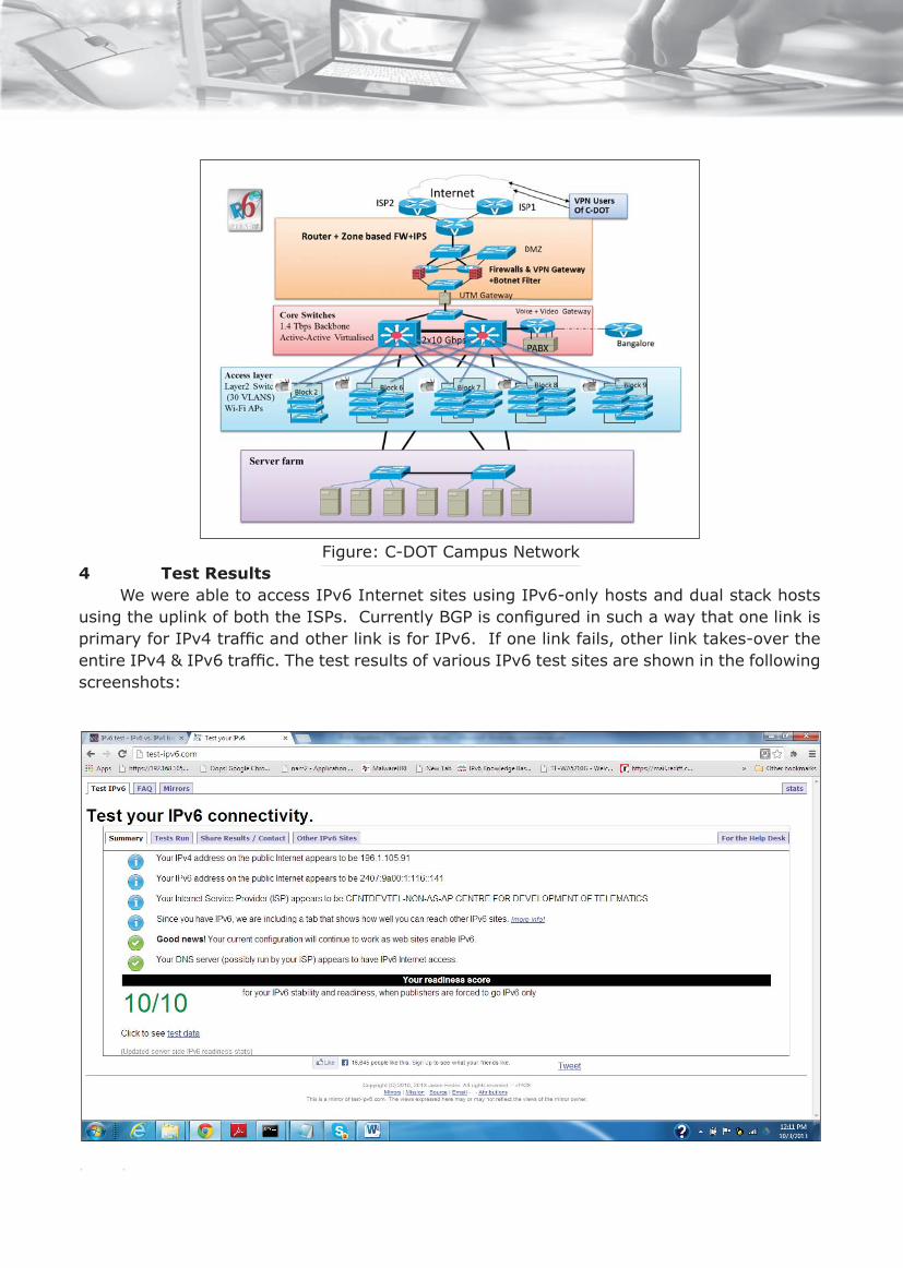
44
Figure: C-DOT Campus Network4 Test Results
We were able to access IPv6 Internet sites using IPv6-only hosts and dual stack hosts using the uplink of both the ISPs. Currently BGP is confi gured in such a way that one link is primary for IPv4 traffi c and other link is for IPv6. If one link fails, other link takes-over the entire IPv4 & IPv6 traffi c. The test results of various IPv6 test sites are shown in the following screenshots:

45
5 ConclusionThe IPv6 transition, based on dual stack model for our campus was very smooth and
exciting for us but real challenge is managing and ensuring the security of IPv6 traffi c. When deploying the IPv6, it is important to ensure that necessary security capabilities exist on the edge routers when dealing with IPv6 traffi c.
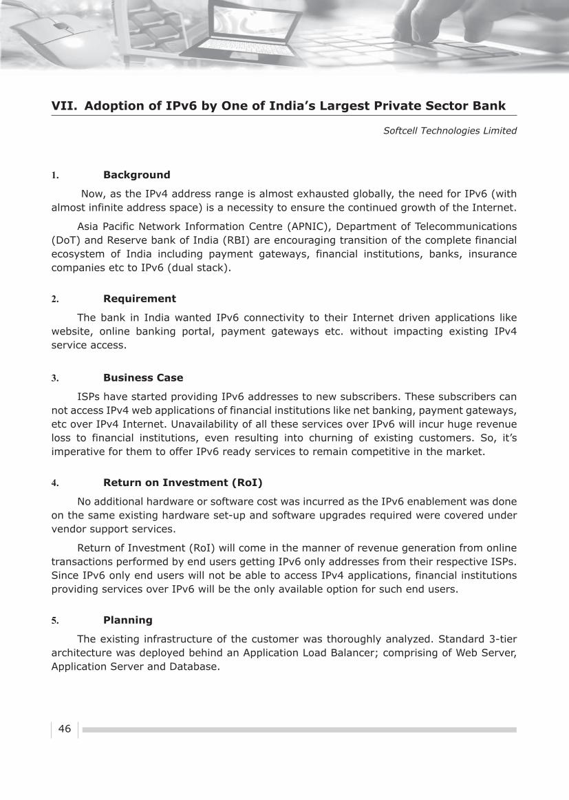
46
VII. Adoption of IPv6 by One of India’s Largest Private Sector Bank
Softcell Technologies Limited
1. Background
Now, as the IPv4 address range is almost exhausted globally, the need for IPv6 (with almost infinite address space) is a necessity to ensure the continued growth of the Internet.
Asia Pacific Network Information Centre (APNIC), Department of Telecommunications (DoT) and Reserve bank of India (RBI) are encouraging transition of the complete financial ecosystem of India including payment gateways, financial institutions, banks, insurance companies etc to IPv6 (dual stack).
2. Requirement
The bank in India wanted IPv6 connectivity to their Internet driven applications like website, online banking portal, payment gateways etc. without impacting existing IPv4 service access.
3. Business Case
ISPs have started providing IPv6 addresses to new subscribers. These subscribers can not access IPv4 web applications of financial institutions like net banking, payment gateways, etc over IPv4 Internet. Unavailability of all these services over IPv6 will incur huge revenue loss to financial institutions, even resulting into churning of existing customers. So, it’s imperative for them to offer IPv6 ready services to remain competitive in the market.
4. Return on Investment (RoI)
No additional hardware or software cost was incurred as the IPv6 enablement was done on the same existing hardware set-up and software upgrades required were covered under vendor support services.
Return of Investment (RoI) will come in the manner of revenue generation from online transactions performed by end users getting IPv6 only addresses from their respective ISPs. Since IPv6 only end users will not be able to access IPv4 applications, financial institutions providing services over IPv6 will be the only available option for such end users.
5. Planning
The existing infrastructure of the customer was thoroughly analyzed. Standard 3-tier architecture was deployed behind an Application Load Balancer; comprising of Web Server, Application Server and Database.

47
Figure: Existing Infrastructure
6. Challenges
Following challenges were identified during the assessment of existing setup of the customer:
� Initially only IPv4 services were running on network infrastructure as well as software stack. There was a need to ensure that the changes required to deploy IPv6 services on the same setup should not alter existing IPv4 services in any way.
� During the IPv6 deployment activity, IPv4 website and applications should remain available over the Internet.
� Standalone IPv6 infrastructure in addition to existing IPv4 setup would have incurred cost implication due to duplication in software, hardware, network and other resources. It would also require additional IT resources to manage the setup.
� Existing web cache server did not support IPv6 network stack.
7. Solution
Dual stack mechanism was selected as IPv6 enablement could be done without impacting IPv4 services, during as well as after the IPv6 deployment. Also dual stack method does not require additional standalone IPv6 infrastructure.
Challenge of lack of IPv6 support on the web cache server was to be addressed by implementing 6-to-4 NAT on Application Load Balancer, so that IPv6 client requests could be translated and forwarded to IPv4 address space of the web servers.
8. Execution
The deployment of dual stack mechanism was completed in following manner:
� Network Assessment for Dual-stack Support: Availability of end to end IPv6 dual stack support on network, security and application devices in core and distribution layer was verified.

48
� IPv6 Address Space from ISP: After analysing customer’s current as well as future requirement of number of IPv6 addresses, an IPv6 address block of /64 was acquired from ISP for the setup.
� IPv6 DNS service with AAAA (record) from ISP: Authoritative DNS services for IPv6 for the domain name were enabled. IPv6 (AAAA) record was added in authoritative DNS for the public facing web servers.
� Redundant IPv6 Connectivity from ISP: Dual IPv6 physical connectivity with virtual IPv6 address was acquired from ISP for high availability.
� IPv6 Enablement in Customers Set-up: The following steps were performed:
� IPv6 enablement was performed on one web server at a time in such a way that existing IPv4 services kept on running unaffected on other servers.
� Load balancer and content caching acceleration appliance were configured to temporarily isolate a single web server from production network.
� 6-to-4 NAT was implemented on load balancer so that IPv6 requests could be translated into IPv4 and forwarded to the web cache server running on pure IPv4.
� Configuration changes were done on firewall to allow IPv6 clients to access HTTP and HTTPs on virtual IPv6 address.
� Upon successful access, isolated webserver was brought back into production and same steps were followed for remaining webservers.
Figure: Infrastructure after IPv6 transition
9. Testing
The website was tested for IPv6 over Internet by using online tools such ashttp://ipv6-test.com as well as IPv6 enabled client machines.

49
10. Conclusion
The website of the bank was accessible over IPv6 Internet post IPv6 enablement activity. The activity was completed successfully by Softcell under stipulated time window with near zero downtime. IPv4 services were not impacted during as well as post activity.
11. Benefits & Key Insights
� Zero impact on the website availability over IPv4.
� IPv6 was deployed while supporting IPv4 services simultaneously.
� IPv6 address space, IPv6 DNS service and dual IPv6 physical connectivity were acquired from ISP in short duration.
� Lack of IPv6 support on web cache server was addressed by implementing 6-to-4 NAT on Application Load Balancer, so that IPv6 client requests were translated into IPv4 address space and forwarded to web server.

50
VIII. Smart Grid: Powered by IPv6
1. Introduction
The global climate change and rapidly growing populations over the past decades have generated increasing demands for abundant, sustainable, and clean electric energy on a global basis. In India increasing energy demand means an even heavier burden on the already overstressed and fragile electricity infrastructure, almost 50–60 years old. Over the last several years, the electricity demand and consumption have increased at an average rate of 6% and expected to stay at around 5.2% as per reports available. The network congestion and safety-related factors have become the main causes of several major blackouts that happened in recent years. Based on the reports available India’s network losses, both technical and non-technical, exceeded 32% in 2010, compared to world average of less than 15%. The Government pegs the national T&D losses at around 24% for the year 2011 & has set a target of reducing it to 17.1% by 2017 & to 14.1% by 2022.
To address these challenges, a new concept of next generation electric power system, Smart Grid has emerged. The smart grid is a modern electric power-grid infrastructure for improved efficiency, reliability, and safety, with smooth integration of renewable and alternative energy sources, through automated control and modern communication technologies. The impact of equipment failures, capacity limitations, and natural accidents and catastrophes, which cause power disturbances and outages, can be largely avoided by online power system condition monitoring, diagnostics, and protection. In this respect, the intelligent and low-cost monitoring and control enabled by online sensing technologies have become essential to maintain safety, reliability, efficiency, and uptime of the smart grid.
These low power and low cost sensing devices known as the 6LoWPAN (IPv6 over Low power Wireless Personal Area Network) devices in the network work together to connect the physical environment to real world applications. And considering the fact that several hundreds of millions of Smart Meters along with the sensors need to be connected to the network, there is an acute need for unique IP addresses. But IP addresses in the existing IPv4 (Internet Protocol version 4) are exhausted. Hence it becomes mandatory to adopt IPv6 platform for the Smart Grid application, which apart from providing virtually infinite unique addresses also provide other advantages like auto-device configuration, built in security and multicasting.
These features of IPv6 which are especially relevant to the Smart Grid are detailed below -
Auto-Configuration: Sensor devices need to be configured with several parameters to make them ready for communication at the network layer. Manually configuring these devices becomes extremely difficult especially when several hundreds of sensor devices need to be configured. In contrast, auto configuration allows hot plug-in of the network devices, as the devices configure their own IP addresses automatically without any user involvement.

51
Security: The sensor networks have resource constraint in terms of processing power and network bandwidth put limitations on security. Therefore, new lightweight security mechanisms appropriate for sensor networks have to be used which could be made possible on an IPv6 platform.
Mobility Management: The point of attachment of the sensor devices to the Internet could be fixed or dynamic. When roaming takes place between different communication technologies such as a WLAN connection to a mobile connection, it becomes difficult to resolve at the link layer and has to be handled at the IP layer. So in case of an IPv6 enabled sensor devices NEtwork MObility (NEMO) provides a solution for mobility management.
Multicast: IP Multicast technologies enable scalable distribution of data, voice, and video streams efficiently to hundreds, thousands, even millions of users. IPv6 Multicast utilizes a single data stream, which is replicated by routers at branch points throughout the network. This mechanism uses bandwidth much more efficiently and greatly decreases load on content servers, reaching more users at a lower cost per user. This IPv6 feature thus resolves the traffic congestion problems.
2. Definition
Smart Grid is an evolving set of various technologies, especially information and communication technologies, working together to improve the present grid. Industry has given various definitions. However Smart Grid, in nutshell can be defined as a power system capable of two-way communication between all the entities of the network-generation, transmission, distribution and the consumers. The aim of smart grid is to provide real-time monitoring and control, and thus improve the overall efficiency of the entire system apart from inclusion of renewable energy resources into the system.
3. Need for Smart Metering
The electricity system that supplies the energy to support increasing consumer demand has not kept the same pace. The meters that measured how much electricity customers are using have not changed since 1950s. The meters never knew that there is an outage in the system. But the meters proposed to be used in the Smart Grid can even detect the outage and convey the same to all concerned due to two way communication. Also there is a self healing mechanism built into the smart grid system which can detect the fault, diagnose and itself heal without any manual intervention. There is also a growing need for electric vehicles to reduce the green house CO2 effect and to have a green transport system. Also there is a need for the use of renewable energy sources like solar, wind etc., as there is depletion in the fossil fuel. So for effective utilization of the conventional energy and the renewable energy, integration of these sources to the grid is mandatory. All these are possible with the Smart Grid only. So there is a need for investment in this 21st century technology which supports innovations like solar power, electric vehicles etc.

52
4. Smart Grid Drivers
� Aging Infrastructure: Large parts of the existing infrastructure dates back to the 1960s or even earlier and is reaching the end of its useful life. Equipment is under extreme stress during peak demand.
� Integrating Multi-energy Sources: As the fossil fuel is getting depleted, there is a need to use the renewable energy sources such as wind and solar. But these sources are intermittent, hence an intelligent grid is required to interconnect the existing conventionally generated power with the renewable energy sources for uninterrupted supply power to consumers.
� Lower Energy Prices: With the increasing awareness among the consumers, they look forward to lower tariff. And with the Government pushing privatization policies, it could lead to more competition and lesser energy prices.
� Sustainability: Public interest groups are putting pressure on politicians to reduce CO2 emissions through the adoption of alternative energy sources and to have regulations to increase energy efficiency. This could only be possible by the Smart Grid Technology.
� Revenue Protection: Losses due to consumer theft or billing deficiencies is said to be around 10–15%. So there is a need for better technology that can safeguard these aspects.
� Operational Efficiency: Electricity losses in India during transmission and distribution are said to be about 24%. This calls for better efficiency in all these fronts as it is well said that “Energy saved is Energy generated”.
� Customer Satisfaction: The inability to supply during the peak demands and faults leading to break down of the grid resulting in black outs are causing lot of concern for the consumers. Also wrong billing due to faulty meters leads to customer dissatisfaction.
5. Challenges for adoption of Smart Grid Technology
The Smart Grid is broad in its scope, so the potential standards landscape is also very large and complex. The fundamental issue is organization and prioritization, to achieve an interoperable and secure Smart Grid. The major challenges are enumerated below -
Lack of Awareness: Mature standards and best practices are available and can be readily applied to facilitate Smart Grid deployment. The main problem with adoption seems to be a lack of awareness of these standards, best practices and regulatory guidelines by the people.
IPv6 Adoption: IPv6 has many features like auto configuration, security, mobility management, multicast etc., which could be effectively used for the seamless, smooth and successful implementation of Smart Grid, adoption of IPv6 becomes a pre-requisite to Smart Grid adoption.
Technical Challenges: The Smart Grid poses a technical challenge that is beyond the

53
simple addition of an Information Technology Infrastructure on top of an electrical infrastructure. Different stakeholders are responsible for different parts of the system. Independently, each may make different choices about evolution and use. It is now necessary to manage the integration of new equipment.
Standards and Interoperability: One major challenge is integration of numerous equipments from different providers worldwide. There is a huge need for interoperability standards that will allow utilities to integrate equipment from any vendor that will work seamlessly with the existing equipment. This means there is a need for standards at the interface level that enables elements of any vendor to be connected in a plug and play mode.
High Capital Costs: Deployment of AMI requires expenditure on the hardware and software components like meters, network infrastructure and network management software, along with cost associated with the installation and maintenance of meters and information technology systems. This means a huge capital investment in the deployment of smart grid. In the prevailing situation it could be only achieved by the Government supporting the project or playing a key role in encouraging Public Private Partnership (PPP).
Security: As we know that communication is the heart of the Smart Grid, at the same time it is susceptible to all types of cyber threats. So ensuring consumer privacy and security is an issue that has to be adequately addressed.
6. Case Study:
Smart Grid projects in the European countries started as early as 2001. Way back in 2001, Enel, Italy’s most dominant utility started a five-year program to install smart meters across its customer base of 40 million homes and businesses. It was meant to improve efficiency, create higher margins, and help customers reduce their energy bills. As of now 85% of Italian homes are now fitted with smart meters, the highest percentage in the world.
According to ABI Research, the worldwide installed base of smart meters will more than triple from 2008 to 2014, to 180 million units. The EU, with its population nearing 500 million and mandatory installation targets for 2020, represents 64% of that figure, or 115 million smart meters. North America is No. 2 at 45 million units, with Asia Pacific and Latin America third and fourth, respectively.
In India too with the initiative taken by the Government of India, 14 Smart Grid pilot projects are planned in the country. The Smart Grid Pilot Project at Puducherry is one of these 14 pilot projects. This is done jointly by the Power Grid Corporation of India Ltd., and the Puducherry Electricity Department (PED) in collaboration with around 56 organizations consisting of equipment manufacturers, academicians, consultants etc. The major objectives of the pilot project are to test and demonstrate, the effectiveness and functionality of the Smart Grid Attributes like AMI, DR etc., scalability & reliability, arrive at a common platform for seamless interoperability, evolving policies, regulation for large scale implementation.
The Smart Grid Pilot Project is in progress in Puducherry and as of now the Smart Grid Control Centre is established with around 1400 smart meters along with 8 numbers of Data Concentrator Units (DCU) & 12 DT meters deployed in the field as part of AMI, which is the foundation of Smart Grid. At present Smart Grid attributes such as AMI, OMS, PQM,

54
Demand Response, Net Metering, Smart Home, 3D map of feeder, Electric Vehicle and Street Light Automation has been implemented. Other initiatives like Renewable Energy Integration, Micro grid, Energy Storage are also in the process of implementation. The present status of the various attributes of Smart Grid implementation in Puducherry is enumeratedbelow -
Advanced Metering Infrastructure (AMI): Smart Meters from 13 different vendors working with different communication technologies like PLC, RF (2.4GHz), RF (865 MHz) & GPRS are deployed. They all are integrated with the common Meter Data Management (MDM) to check for interoperability and Standardization. This pilot test would help in freezing the common platform on which equipments from different manufacturers would work seamlessly. Two modes of communication with the control centre are implemented and tested. In first mode, SIM card is embedded in the Smart Meter and using GPRS it directly communicates with the Control Centre. In the other mode the Smart Meter communicate with the Data Concentrator Unit (DCU) on RF. DCU has the embedded SIM card and concentrates the data from a cluster of around 50 AMIs and in turn communicates with Control Centre using GPRS. With the AMI implementation it is possible to monitor and control the following:
(i) Reduction in AT & C losses
(ii) Reduction in cost of billing
(iii) Facilitating DT wise energy Accounting/ Auditing
(iv) Facility to connect and disconnect load by command
(v) Better load management
(vi) Monitoring power quality information
(vii) Monitoring of outage data
(viii) Generation of alerts for tampers and sending to control centres
Outage Management System: In this implementation six Distribution Transformer Monitoring Units (DTMU) as well as six Fault Passage Indicators (FPI) has been installed. DTMU’s monitor various parameters of the Distribution Transformers (DT) like oil level, oil temperature, load current, voltage, harmonics, palm temperature etc. These data are captured using sensors and sent to the control centre using GPRS communication at regular intervals. OMS facilitates the following:
(i) Easy and early detection of faults using Fault Passage Indicator (FPI)
(ii) Status of fault in the phase is communicated remotely
(iii) Outage Data is made available along with timestamp, feeder details, etc.
(iv) Preventive maintenance for transformers
(v) Better Network Management - load redistribution and more efficient use.
(vi) Total Harmonic Distortion value to monitor power quality
Demand Response (DR): A demonstration model of demand response has been set

55
up which facilitates customer energy dashboard to receive utility signals and to respond to load shedding. Customer energy dashboard is installed at the customer premises and it was demonstrated live by controlling AC and lighting in SGCC. DR facilitates the following:
(i) Facilitating consumer engagement in the energy management process by regular price and usage information
(ii) Consumer responds to price signals by changing consumption behavior
(iii) Utility is able to better manage power supply deficit and surplus situation
(iv) Utility can defer need for capital intensive power capacity addition
Street Light Automation: Street Light Automation was also implemented in Puducherry. It was observed that the energy consumption reduced by around 20%. With this implementation it is possible to monitor and control the following:
(i) Street light switch on and off automatically
(ii) Dimming and brightening of street lights based on traffic conditions, thus saving energy when there is very less traffic eg. During late night hours
Power Quality Management: In this implementation LT Automatic Power Factor correction is possible. Power Quality Management system is essential to monitor power quality at regular intervals and automatically ensure better power factor, provide better compensation for reactive power and weed out harmonics from the system. POWERGRID has installed a capacitor bank that will manage power quality (voltage support) by automatic switching of capacitor bank.
Net Metering: The net meters can measure not only the electricity drawn from the grid, but also what is fed into it. This feature was tested which enabled the customer to know how much energy is fed into the grid from his roof top solar panel and also how much the customer is drawing from the grid. At present further testing is in process for grid-interactive rooftop scheme. The idea is to demonstrate technical and administrative feasibility of grid-interactive rooftop solar PV systems which will pave way for a solar energy policy for Puducherry.
Electric Vehicles: POWERGRID is working with different vendors to develop Vehicle to Grid (V2G) wherein electric vehicles along with many charging stations will be developed for supply to grid when the grid needs it and vice versa. Demo of Solar charging facility for Electric Vehicle and interconnection with Grid is in progress. Also, using sensors, various parts of EV are remotely monitored at present.
7. Benefits of Smart Grid:
Benefits to Utility:
(i) Reduction in AT & C losses
(ii) Increased Grid stability

56
(iii) Peak load management
(iv) Renewable integration
(v) Self-healing grid
(vi) Reduced capital & operational cost
(vii) Increased employee safety
(viii) Increased revenue
(ix) Higher customer satisfaction
(x) Opportunity to leverage its resources and enter new markets
(xi) Increased asset utilization
Benefits to Consumers:
(i) Prosumer (Producer and consumer ) enablement
(ii) Improved quality of supply
(iii) User friendly & transparent interface with utilities
(iv) Reduction in electricity bills by shifting loads from peak hours to non-peak hours
(v) Opportunity to interact with the electricity markets through home area network
(vi) Opportunity to purchase energy from clean resources, further creating demand for the shift from a carbon based to a “Green economy”.
Quantitative Benefits: The Quantitative benefits expected from a Smart Energy Efficient Home are as given below:
a) Impact of Smart Grid Implementation on one crore households (by extrapolating the data obtained in the pilot project) is expected to yield the following benefits:
For an Urban area of 1 crore household
• Peak demand reduction by at least approx. 12000 MW
• Energy consumption reduces by approx. 30 Billion Units
• 26 million tonnes of CO2 reduction per annum
• Reduction in infrastructure investment by 1lakh crore
b) Investment per Household and Payback Period:
Investment & Payback
Investment per household Rs.35000/-
Payback period ≈ 3 Years

57
The investment per household includes the cost of SMART Meter, and metering infrastructure required at the customer premises to capture the customer data remotely either through a wireless/wired means of communication. But the Investment done by the utility on the Common Smart Grid infrastructure like Control Centre, Data Transmission System, Data Processing and Monitoring, etc may have a payback period of around 5 to 10 years.
c) Average Power Saving through Energy Effi ciency per Household:
Average Power Saving through Energy Effi ciency per Household
Summer Winter
Peak Demand Reduction (Units) 1217 2485
Reduction in monthly consumption (Units) 266 199
The demand reduction and reduction in monthly consumption happened because the consumers were able to meet part of their requirement from renewable energy sources like solar and the remaining from the grid.
d) Value of Saving per Household:
Value of saving per household
Average tariff 4.00/unit
Monthly saving (based on energy saving from table above) Rs.1063/- Rs796/-
Annual Saving (4 months Winter + 8 months summer) Rs.11688/-
Annual air pollution reduction 2.60 tons of co2
The Value of saving per household Table above is calculated based on the reduction in monthly consumption units given in Table 7.3 (c ) above and on the assumption that the average tariff is Rs.4/- per unit. Also it was assumed that there will be 4 months winter and 8 months summer in a year.
e) Benefit to Cost Ratio:
It has been found that the Benefit to Cost ratio varies from 3.85 to 4.2 and with an average of 4 it is said that investment in smart grid would be a profitable investment.
8. Conclusion:
The transformative power of the smart grid is enormous. The smart grid has the potential for revolutionizing the way we produce and consume electricity. The new services enabled by the smart grid will include different rate designs that encourage curtailment of peak loads and make more efficient use of energy. Examples include dynamic pricing and inclining block rates. These innovative rate designs will be enhanced by various automating

58
technologies such as programmable communicating thermostats (PCTs), whole building energy management systems (Auto DR), and in-home displays (IHDs).
Smart Grid requires IPv6 platform to reap the full benefit of the Smart Grid infrastructure and its applications like AMI, DR, EV etc., hence IPv6 adoption in India is a prerequisite for Smart Grid implementation. The smart grid is posed to go beyond smart meters and rate design and enable renewable energy resources to be connected to the grid. This will allow optimal use of intermittent resources, such as solar, wind, which often reach their peak generating capacity during off-peak hours. New off-peak loads, such as plug-in hybrid electric vehicles, which reduce overall energy consumption and improve the carbon footprint, will be energized by the smart grid. Smart Grid can therefore become a platform for all the innovative services of the future.
Smart Grid can usher India from a power dependent country to self reliant country in power, apart from the benefits of so many innovative services that could boast the socio-economic growth of the country and launch India as the next economic super power.
9. References
1. https://apps.powergridindia.com/smartgrid/plm.aspx
2. http://www.smartenergyuniverse.com/smart-grid
3. http://energy.gov/oe/technology-development/smart-grid
4. http://smartgrid.ieee.org/ieee-smart-grid-experts?start=20
5. http://www.smartgrids.eu/
6. http://indiasmartgrid.org/en/Pages/Index.aspx
7. http://electricity.puducherry.gov.in/
8. http://www.powergridindia.com/_layouts/PowerGrid/User
9. http://www.mnre.gov.in/
10. http://www.iea-isgan.org/
11. http://www.nist.gov/smartgrid/
12. http://www.netl.doe.gov/smartgrid/
13. http://en.wikipedia.org/wiki/Electricity_sector_in_India
14. http://smartgrid-for-india.blogspot.in
17. http://www.indiaenergyportal.org
18. http://www.thehindubusinessline.com

59
IX. A Pilot Project on 6LoWPAN for Last Mile Connectivity for AMI
Reliance Infrastructure Ltd.
1. Introduction & Background
Last mile networks have gained considerable momentum over the past few years due to their prominent role in the Smart Grid infrastructure. These networks support a variety of applications including not only electricity usage measurement and management, but also advanced applications such as Demand-Response (DR) [which gives users the opportunity to optimize their energy usage based on real-time electricity pricing information] and Distribution Automation (DA) [which allows distribution monitoring and control alongwith automatic fault detection, isolation and management]. This serves as a foundation for future Virtual Power Plants, which comprise distributed power generation, residential energy storage (e.g. in combination with Electric Vehicle (EV) charging) and small scale trading communities.
This has created the need for deploying the IP (Internet Protocol) suite of protocols enabling the use of open-standards that provide reliability, scalability, security, inter-networking and flexibility required to cope with the fast-growing number of critical applications for the electric grid that distribution power networks need to support. IP also facilitates integration of the Neighbourhood Area Networks (NAN) into end-to-end network architecture. One of the major steps in favour of building the momentum around using IP end-to-end in the last mile of Smart Grid networks was to demonstrate that IP could be light enough (6LoWPAN) to be used on constrained devices with limited resources in terms of energy, memory, and processing power. Finding the right network technology to meet the demands of the fu ture is not that easy. Wireless IP mesh networks have a sig nificant share of metering de ployments around the world which is generating a high level of interest globally. As the market moves towards even higher demands for safety, interoperability and robustness, it makes perfect sense to bring Internet technology all the way to the meters and its peripherals now that standardization within M2M converges with IP as common denominator.
2. Internet of Things & 6LoWPAN
The Internet of Things (IoT) is happening right now and will play a disruptive role in virtually all types of businesses, including Smart Energy and Smart Metering. Low power devices with limited processing capabilities should be able to participate in IoT. Even the smallest device could & should have IP is the idea behind IPv6 over Low Power Wireless Personal Area Network (6LoWPAN).
The Internet Engineering Task Force (IETF) oversees the 6LoWPAN standardization and specification work under Request for Comments (RFC) 4944. The specifications are open and developers can buy 6LoWPAN code, use open-source code or write their own. But 6LoWPAN communications don’t require a complete rewrite of an IEEE 802.15.4 radio stack. Instead, 6LoWPAN adds an adaptation layer that lets the radio stack and IPv6 communications operate together.

60
3. Key Advantages of 6LoWPAN
One of the differences between Information and Communications Technology (ICT) and traditional power industry is the lifetime of technologies. Selecting the IP layered stack for Advanced Metering Infrastructure (AMI) brings future proofing through smooth evolutionary steps that do not modify the entire industrial workflow. Key benefits of IPv6 for a Distribution System Operator (DSO) are:
� Open and Standards Based: Core components of the network, transport and applications layers standardized by the Internet Engineering Task Force (IETF) while key physical, data link, and applications protocols come from usual industrial organizations, such as IEC, ANSI, DLMS/COSEM, IEEE etc.
� Lightweight: Devices in AMI network are not like PC and servers. They have limited resources in terms of power, CPU, memory and storage. Therefore, an embedded networking stack must work on few kilobits of RAM and a few dozen kilobits of flash memory.
� Versatile: Last mile infrastructure in Smart Grid has to deal with two key challenges. First, one given technology (wireless or wired) may not fit all field deployment’s criteria. Second, communication technologies evolve at a pace faster than the expected 15 to 20 years lifetime of a smart meter. The layered IP architecture is well equipped to cope with any type of physical and data link layers, making it future proof as various media can be used in a deployment over a considerable time, without changing the whole solution architecture and data flow.
� Ubiquitous: All recent operating systems releases from general-purpose computers and servers to lightweight embedded systems (TinyOS, Contiki, etc.) have an integrated dual (IPv4 and IPv6) IP stack that gets enhanced over time. This makes a new networking feature set easier to adapt over time.
� Scalable: IP has been massively deployed and tested for robust scalability.
� Manageable and Secure: Communication infrastructure requires appropriate management and security capabilities for proper operations. Adopting IP network management also helps utility operational business application by leveraging network-management tools to improve their services, for example when identifying power outage coverage through the help of the Network Management System (NMS).
� End-to-end: The adoption of IP provides end-to-end and bi-directional communication capabilities between any devices in the network.
Note—Using the Internet Protocol suite does not mean that an infrastructure running IP has to be an open or publicly accessible network. Indeed, many existing mission-critical but private and highly secure networks leverage the IP architecture; such as inter-banking networks, military/defence networks and public-safety & emergency-response networks, to name a few.

61
4. Comparison between 6LoWPAN & ZigBee Networks
� Stack size: The stack size of 6LoWPAN with full functionality is approximately 30K which is nearly half the size of ZigBee stack size. The figure below illustrates the difference between ZigBee and a 6LoWPAN stack:
Figure: Difference Between ZigBee & 6LoWPAN
The comparatively smaller footprint of the stack size of 6LoWPAN enables user to choose a micro controller of suitable ROM/FLASH size which is directly proportional to the cost of the device.
� Interoperability: Interoperability is one of the leading factors when choosing a wireless protocol. In technical terms, interoperability means that the applications do not need to know the constraints of the physical links that carry their packets. ZigBee defines the communication between 802.15.4 nodes (layer2 in the IP world) and then defines new upper layers all the way to the application.
This means ZigBee devices can interoperate with only other ZigBee devices, assuming they utilize the same profile. 6LoWPAN offers interoperability with other wireless 802.15.4 devices as well as with devices on any other IP network link (e.g. Ethernet or Wi-Fi) with a simple bridge device.
� Connectivity to the Internet: ZigBee is an alliance which specifies a vertical protocol solution on-top of the IEEE 802.15.4 radio. Traditional ZigBee networking protocols are not directly compatible with the Internet as compared to 6LoWPAN.
� Distance Coverage: Most radio chip vendors adopt ZigBee on 2.4GHz band which has less area coverage without a power amplifier. 6LoWPAN operates independent of the frequency of operation; 6LoWPAN for sub GHz band provides more area coverage for the same output power.

62
� End-End Connectivity: ZigBee network solutions have a middleware to talk between servers and nodes whereas the 6LoWPAN network doesn’t use a middleware for translation.
5. Why 6LoWPAN for Smart Metering in AMI Infrastructure
Smart Metering is a key segment for M2M – but based on market experience about 10-40 % of the meter population cannot be reached reliably by a cellular connection. In addition there is a clear business benefit to locally concentrate traffic from low-value applications; the very large numbers of connections in M2M, plus local device-to-device signaling creates chal-lenges for mobile systems.
Yes…The Missing link is Wireless IP Mesh!
A wireless 6LoWPAN/CoAP/802.15.4-based solution, also conforming to the OMA Lightweight M2M protocol is the prime candidate for large-scale Local (Neighbor-Area) Networks that complement the cellular network and act as a true enabler of the IoT. The wireless mesh fits seamlessly into an existing telecom infrastructure both from a technical and from a process/com petence point of view; complementing the conventional telecom networks as a ge neric platform for a wide range of different applications. Last, but not least, it is cheaper – both in terms of CAPEX & OPEX.
Some Facts:
� IoT was “born” sometime be tween 2008 and 2009, when the number of connected devices outnumbered world population.
� By 2020 there will be 50 bil lion connected devices for only 7.6 billion humans.
� IoT can make a significant dif ference in closing the poverty gap by improving utilities’ in frastructure and dealing with problems such as inefficiency and theft.
6. Pilot Implementation of 6LoWPAN RF Mesh for AMI
Scope & Extent: The Pilot is expected to run for approximately 6-8 months from installation. After that time the product will be regard ed as normal operation, unless the installation is removed. A possible test bed of 50 to 100 units is selected for installation in a suitable area within the territory of Reliance Energy. The tested hardware units of radio module board will fit into Landis+Gyr E350 meters. After a successful pilot project, it is easy to go into regular meter operation. The reminder network can gradually scaled up as per the requirement of the utility.
The Pilot Project is based on these Open Standards:
� 802.15.4.g (Radio Communication in Mesh Network)
� 6LoWPAN (End-to-end IP connectivity)
� CoAP (HTTP like application protocol)
� DTLS (security layer similar to TLS for web)

63
7. How it Works –The Architecture
The diagram below illustrates the solutions architecture for deployment in a Smart Metering context where Mesh Termi nals and Gateway Terminals are embedded into Smart Meters connected to the server back-end application over a cellular network and the IEEE 802.15.4g MAC/PHY is used for all radio mesh networks:
Figure: Architecture for Deployment in a Smart Metering ontext
� A 3-tier Architecture: The architecture follows a 3-tier model with one server application, some Gateway Terminals and many Mesh Terminals.
� Server Application: The server is an open modular plat form which provides device management, to pology management, firmware management, SLAs monitoring, security management and DNS support. It is a fully scalable and redundant telco-grade platform, also conforming to standard relevant IT and telecommunications protocols. The server identifies the back-end application providing both a web interface and - more importantly - web services for device, system, security and topology man agement. Third party business applications can also benefit from a “payload pass-through” web service to directly deliver payloads to and from devices. Topology management includes the mainte nance of the topology map across all mesh networks, the ability for devices to switch to another mesh network, the IP routing to all devices or the transport of IPv6 traffic directly over an IPv6 backbone or over an IPv4 tunnel. As a complete system may consist of mil lions of nodes and for larger installations, the server application may be deployed in one or more data centers to provide high availability. Alternatively, the functional ity can be delivered as a cloud service.

64
� Gateway Terminal: A radio mesh network contains only one Gate way Terminal, although the individual mesh terminals may migrate between networks as conditions change. A Gateway Terminal identifies the embedded firmware running in devices with the ability to forward traffic from a radio mesh network to the Internet and from the Internet to a ra dio mesh network. A Gateway Terminal acts as a gateway between a radio mesh network and the Internet enabled backhaul connection (cellular link, satellite link, Ethernet to fiber connection etc.). There is no need for any NAT function in a Gateway Terminal as all devices communicate over 6LoWPAN and IPv6 (IPv6 traffic is transported over IPv4- only Wide Area Networks). An IPv6 prefix is assigned to each Gateway Terminal which manages its own radio mesh network or 6LoWPAN over Routing Protocol for Low-Power and Lossy Networks (RPL).
� Mesh Terminal: A Mesh Terminal identifies the embedded firmware running in all devices equipped to join a radio mesh network. A set of radio Mesh Terminals dynamically maintains the mesh topology using RPL to provide con nectivity to the Gateway Terminal and the Internet for all devices in this radio mesh network.
8. Services Offered
� Management Service: The management service regroups all features within the scope of device management, topol ogy management, Over-The-Air-Provisioning (OTAP), SLAs monitoring and DNS support for instance. The security service regroups all features within the scope of mutual authentication between the Smart Meters and the server, the encryption of any sensitive over-the-air transaction (meter readings, firmware update etc.) as well as the initial provisioning of the necessary security credentials, the revocation of certificates, cipher suite upgrades, key store management, secure boot, code signing etc.
� Communication Service: The communication service regroups all fea tures within the scope of communication over a radio mesh network as well as the com-munication over a cellular or other network. Each terminal runs a standard IPv6/6LoWPAN stack and all applications within a terminal are built on top of Constrained Application Protocol (CoAP) and Efficient XML Interchange (EXI).
� Smart Metering Service: Finally the smart metering service regroups all features specific to a smart metering deployment such as the collection of meter readings pushed from terminals to the server at periodic intervals or the on-demand re-quest from the server for instantaneous me ter readings etc.
9. Global IP Reachability
Each Gateway Terminal forwards IPv6 traffic coming from the Internet to the devices in the radio mesh network over 6LoWPAN and forwards 6LoWPAN traffic originated from the radio mesh network to the Internet over IPv6. Therefore global IP connectivity from anywhere to each device can be achieved if the routing information of the IPv6 prefix al located to each 6LoWPAN is advertised over the backhaul link of each Gateway Terminal. If the backhaul link

65
does not support IPv6 natively, an IPv4 tunnel should be setup with the server to proxy the transport of the IPv6 traffic transparently. The ability to run business applications and CoAP services on a device from anywhere and especially from an end-customer location is only limited by the security model to enforce and the requirements to distribute the appro priate security credentials for authentication and encryption.
10. Ecosystem Integration
An extensive and extensible application pro file is defined on top of CoAP-EXI for the dis covery and use by any backend application of all services provided by these devices. A web service interface is provided by the server application for north-bound integration into the ecosystem as well as a HTTP-CoAP proxy to third-party applications (and pos siblyend-customers) for easy integration of additional Value Added Services directly tar geting the end devices (add-on model). Also well-known tools such as ping6 and traceroute6 are supported to investigate net working issues.
11. Reduced CAPEX & OPEX
� No Dedicated Networking Equipment Required: One fundamental property of this technology is to consider Mesh Terminals and Gateway Termi nals as equivalent for most use cases. In the context of smart metering for instance, both Mesh Terminals and Gateway Terminals will be embedded into Smart Meters and collect meter readings. Doing so eliminates the need for an installer to deploy any additional piece of networking equipment without any real business value; thus reducing the CAPEX and OPEX for each installation.
� Free Radio Spectrum and Self-Configuring Radio Mesh Networks: The use of a free license radio spectrum for most of the data communication in the sub GHz range decreases both the CAPEX and OPEX of the radio part for all devices. Also the self-configuring nature of radio mesh networks reduces significantly both the com-plexity of the radio planning steps and the complexity of the provisioning steps compared to other networking technologies. The provisioning step for each terminal be fore or during installation is mostly limited to the provisioning of the security creden tials. Also the return of experience related to the “clean-up” phase during which in stallers need to fix remaining connectivity issues by adding external radio antennas for instance indicates that this effort is very limited in scope.
� Optimization Over the Backhaul Link: The firmware management feature of this platform enables an operator to schedule the secured transfer of a new firmware image to each Gateway Terminal over a backhaul link (cellular connection or satellite link for in stance). Once a firmware image is success fully transmitted to a Gateway Terminal, it is then distributed to all Mesh Terminals of this mesh network using the broadcasting feature of radio. Such design reduces signifi cantly the need for bandwidth over the back haul connections and the associated OPEX cost during the firmware upgrade of a large population of devices.

66
12. Pilot Deployed Site
The Pilot was deployed at Bandra, Mumbai as shown in the figure below:
13. Web Interface
The screen shot of web interface is shown in the figure below:
Figure: Site of Pilot Deployment at Bandra, Mumbai
Figure: Web Interface

67
14. Conclusion
� Deployed around 100 6LoWPAN meter nodes – sub GHz(865-867MHz).
� Periodic meter data is being collected successfully.
� Sub GHz, 865-867 MHz devices were more efficient in terms of distance coverage.
� The architecture has proven to be highly flexible.
� The networking requirements namely flexibility, reliability, QoS, security, manageability and scalability, which are absolute requirements explains why IPv6 was evaluated as the most appropriate networking architecture for last mile connectivity.
� We are at the beginning of an exciting journey that will extend the use of IPv6 to billions of devices for AMI infrastructure.
� To summarize, the adoption of IPv6 based networking for all Smart Grid services allows all devices involved to be managed through a single network view. All devices and the relationships between them at the IP level can be defined in the network management application and the impact of the failure of communication to any given device can be instantly evaluated and displayed.
15. References
[1] IEEE 802.15.4: IEEE Computer Society, “IEEE Std. 802.15.4-2003”, “IEEE Std. 802.15.4-2006” and “IEEE Std. 802.15.4-2011”.
[2] 6LoWPAN: RFC 4944 and associated.
[3] RPL: RFC 6550 and associated
[4] DTLS: RFC 6347 and associated
[5] COAP: IETF, draft-ietf-core-coap
[6] EXI: W3C (World Wide Web Consortium) Recommendation 10 March 2011
[7] ICMPv6: RFC 4443 and associated
[8] DNS IPv6: RFC 3363, RFC 3901 and associated
[9] IEEE 802.15.4g: IEEE Computer Society, “IEEE Std. 802.15.4g”
[10] www.eetimes.com

68
1. Background
The National e-Governance Program (NeGP) aims to significantly transform and improve the way the Government provides services to its citizens. It is envisaged to move from a Government-centric to a citizen-centric paradigm in service provisioning, to start treating citizens as customers and to empower them to demand convenient, cost effective and transparent services from the Government.
NeGP comprises of several projects spread across a number of sectors which are to be implemented either by the line Ministries/Departments at the Central Government or by State Governments, as well as integrated projects spanning across multiple Ministries/Departments. To support implementation of the Mission Mode Projects under NeGP and also to ensure adherence to common principles and policies towards realization of the vision, NeGP has identified 3 core components as follows:
o State Wide Area Network (SWAN)
o Common Service Centre (CSC)
o State Data Centre (SDC).
SDC is envisaged to establish a robust infrastructure to enable the Government to deliver the services quickly and effectively to its stakeholders. The State Data Centre connected to the State Wide Area Network (SWAN), shall provide the access to the e-Governance applications & services to Government employees through Intranet and to the citizens through public Internet/CSCs etc. Through such a Shared Service Centre implemented and managed by a competent implementation agency, the individual departments can focus more on the service delivery rather than on the issues surrounding the infrastructure.
Adoption of IPv6 has picked up across the world and especially in the Asian region because of the severe shortage of IPv4 addresses. The international scenario on IPv6 gives us a direction as to where the world is heading and what the future holds for India as a country. Accordingly, the Government of Maharashtra had foreseen the implementation of IPv6 in SDC/SWAN and Mantralaya. The objective of this initiative is to address Government compliance and to avoid any IP addresses shortages and crunch. IPv6 would gear all equipments at SDC/SWAN/Mantralaya along with users and devices which connect to Shared Infrastructure for resource accessibility. The SWAN and SDC need to adopt IPv6 so that various e-services are delivered in a seamless manner to the citizens.
2. Need for IPv6
Besides improving on the addressing capacities of IPv4 by using 128 bits addressing instead of 32 bits, IPv6 have several inherent advantages as well. Keeping in view the same, Government of Maharashtra intended to introduce IPv6 due to the following reasons:
• Mandate fl oated by Department of Telecommunications, Government of India
X. Transition to the Future: IPv6 in Government of Maharashtra

69
• IP Block Scalability
• Security
• Plug & Play
• IP Host Mobility
• Multicast
• Support for Jumbo-Grams
• Innovative Applications
• Fast Packet Movement
• Enhanced QoS
• Wireless Integration
• Easy and Quick Adoption 3. Issues and Challenges
The enablement/implementation of IPv6 is not a one day job. There is a requirement of thorough planning required for implementing IPv6. The approach to IPv6 transition has many components and thus multiple transition options. Determining which option is the right fit requires significant due diligence planning around the endpoints, periphery, network devices and IP infrastructure that will support IPv6. This is critical in determining the transition strategy. Several common frameworks have risen to the forefront as viable options including Dual Stack, Translation and Tunneling.
Moreover, there is a huge dependency on the OEMs of equipments for support of IPv6. Management of an IPv6 environment with EMS/NMS tools is a bit challenging. DNS/DHCP, firewalls, EMS/NMS and IPS/IPDS are all intricately entwined in the IP addressing framework. There are huge complexities involved due to interdependencies between the applications, servers, other network devices and the cloud environment wherein multiple host systems reside on a physical server.
Though there are huge benefits of IPv6 implementation, following are some of the challenges faced during the IPv6 implementation:
• Awareness –The IPv6 awareness among team was the challenge within SDC.
• Interoperability – MH-SDC is the fi rst SDC which provides cloud services with muti-tenancy; therefore it brings lots of challenges to work and interoperate on IPv6.
• IOS/OS Version – Current versions of switches connected within MH-SDC were non-compliant which needed IOS upgrade.
• Application – Code level changes required on customized applications to make IPv6 compliant.
• Operating System – IPv6 enabled on OS and several platforms by default which

70
means it was needed to shut down IPv6 services where it was not required.
• DNS/DHCP – DNS servers were not enabled for dynamic updates which mean all hosts who want to connect to environment register manually.
• Change Management – The change management process was time consuming to enable the successful testing of IPv6 within SDC.
• OEM Limitations – The troubleshooting on multi-vendor equipments on IPv6 was the challenge which needed expert help from every OEM. IPv6 impacts almost all the infrastructure components and critical applications
• Multiple Stakeholders – The troubleshooting for enabling IPv6 within various verticals such as SWAN, SDC and FMS was challenging considering the awareness between people during troubleshooting.
• The Pilot testing for IPv6 was challenging considering the changes required at various levels such as infrastructure, ISP, DNS and domain registration.
• HSRP (Hot Standby Router Protocol) was not supported on inline switches to support both IPv4 and IPv6 simultaneously.
• The ISP (Internet Service Provider) took long time to enable and route IPv6 packet from SDC to their cloud
• The domain registration and IPv6 object group changes took time to modify their database.
• Testing of VMware instances took time considering traffi c needs to fl ow on the same card for both the stacks.
• Testing of packets on multivendor chassis - The traffi c fl ow between multiple equipments took longer and required integration between different teams and OEM transitions.
4. Current Status
Figure: Current Status

71
SDC has successfully implemented IPv6 with planned IPv6 schema for entire backbone including all interim devices, services and ISP end. All the planning for application migration has been done from application side by enabling testing on different platforms. The respective SOP with changes would be rolled out to all application owners shortly.
PoC for IPv6 for the FMS /Mantralaya network has been successfully completed. The IPv6 schema planning and designing has already been performed for all network devices and services. The wireless and DHCP testing has been performed on IPv6. The implementation of schema would be done shortly as designed and planned.
In SWAN, IPv6 schema has been planned considering the diversified reach and connectivity. The SHQ is still in planning stage where the implementation would be done shortly. The video conferencing services have already been tested within SWAN. The PoC has already been done with enabling connectivity between FMS and SDC network on IPv6.
5. Implementation
The entire IPv6 implementation was planned in a phased manner:
• Assessment
• Planning and Design
• Proof of Concept (PoC)
• Rollout and Program Management
Assessment Phase – The assessment phase started with identifying the key stakeholders such as nodal officer from DIT, System Integrator and composite team. The key objective of this activity was to understand the task assigned to each stakeholder. The scope of entire assessment including zones, layers and entire architecture was discussed and finalized during the meeting.
During assessment phase, the area of focus was to understand the complete assets of SDC, FMS and SWAN team. The asset list provided the view of the category and types of devices running in SDC, FMS and SWAN. The list also talked about the applications (both web and customized) running within SDC.
The compatibility and pre-requisites of IPv6 were checked and assessed during assessment phase. All the typical risks and mitigation strategy including transition method were identified along with the training needs for the teams on IPv6.
Planning and Design – The architecture was studied and the changes were assessed during this phase. The roadmap and procedures were prepared for checking the compatibility and enabling the devices on IPv6. The selection of transition method which was best suited looking at SDC, SWAN and FMS was selected as dual stack which is also recommended and suggested by DoT (Department of Telecommunication) for SDC, SWAN and FMS environment. The PoC zone was identified to enable testing within SDC on IPv6. The PoC was specifically targeted for web-services on IPv6. Test web-server was created in DMZ zone and all interim devices such as internet router, internet firewall, and DMZ switch and server load balancer were enabled for dual stack to allow the traffic on IPv6. All changes from Internet Services

72
Provider such as allocation of WAN IP and BGP peering between SDC was done to enable successful PoC. The applications were identified and testing of each platform such as Apache, IIS, Oracle, SQL, Postgre SQL etc were done to assess and check the compatibility and changes required to support IPv6.The PoC for FMS and SWAN was performed by enabling communication between SWAN,SDC and FMS network. The IPv6 subject awareness was done in this phase to enable people to understand the concept and successful transition to new technology.
Proof of Concept (PoC) in SDC – The test server was prepared with sample web-page configured on dual stack (IPv4 and IPv6 IP) on the same Network Interface Card. The coordination with ISP was performed for supplying IPv6 WAN IP for peering with data center. The prepared IPv6 schema was implemented only within one zone to test the packet flow within data center. The domain, DNS registration and IPv6 object group were also updated with IRINN to enable reachability on ISP cloud. For testing IPv6 packets from outside, the ISP was requested to enable IPv6 on a server from their cloud. This server generated the traffic which passed through the data center and reached DMZ zone and vice-versa which assured the successful traffic flow from outside and inside the data center.
Figure: Proof of Concept Environment in SDC

73
Proof of Concept (PoC) in Mantralaya Network- The IPv6 was planned for PoC in Mantralaya network by designing sample IPv6 network schema for Mantralaya LAN. We had enabled Wi-Fi systems by enabling IPv6 IP on it to transfer data from Mantralaya LAN to SDC network. The firewall of Mantralaya network was also enabled on IPv6 to pass traffic through it. The internet connectivity is being served by firewall which is holding the ISP links. We also coordinated with ISP for enabling the configuration required to enable IPv6. By enabling ISP on IPv6 allowed IPv6 traffic to go through the firewall and come back again through the firewall. This has proved and assured about Mantralaya network to be IPv6 compliant and enabled.
Figure: Proof of Concept in Mantralaya Network
Proof of Concept (PoC) in SWAN SHQ – The IPv6 was planned by creating IPv6 schema for entire SWAN mainly SHQ, DHQ, BHQ and THQs. The connectivity between SWAN and SDC was enabled on IPv6. The key equipments within SHQ have been enabled for dual stack. Since BSNL is not ready with IPv6 for now the planning of implementation for DHQ, BHQ and THQ is still under proc ess.
Rollout and Project Management – The designed IPv6 schema was planned and implementation started in phases by targeting all web-enabled traffic first followed by core backbone. The implementation team was well supported by all the changes within environment required to enable IPv6 within SDC, SWAN and FMS network. The mapping of each vertical such as server farm, VLAN, Application, VPN, WAN and Internet in SDC and FMS were done with base IPv6 schema. Proper security control along with optimization of IPv6 traffic was done within SDC, FMS and SWAN for IPv6.
6. Conclusion
IPv6 is a necessity which needs to be proactively planned and implemented to get the most out of it and achieve the benefits. The massive growth of the Internet has demonstrated its value to businesses, Government, professionals, academics and individuals over the last decade. Industry now relies on a range of benefits from Internet technology and has seen significant productivity gains. IPv6 is a future of Internet and a silent revolution.

74
Abstract
IPv4 is history. Future belongs to IPv6. But transition from this history to this future is not devoid of its share of problems. In the business world it is of course a challenge but in the process domains it is all the more cumbersome.
In the domain of process control and instrumentation, SCADA (Supervisory Control And Data Acquisition) is deeply entrenched and fairly standardized. At present it is generally IP agnostic. However, signs of its definite convergence towards IP based communication systems are increasingly becoming evident. It is, therefore, apt to look at the issues, challenges and possible solutions to transiting SoIP (SCADA over IP) from IPv4 to IPv6.
This article presents a methodology for such transition. The transition strategies of the Coke Oven Batteries of Visakhapatnam Steel Plant of Rashtriya Ispat Nigam Limited are also presented as a case study.
1. Introduction
IPv4 has been a phenomenally successful protocol in popularizing IP based transmission and communication. Its immense popularity has led to the exhaustion of the available address space more quickly than expected. To meet the increasing demands on the address space certain technologies are in use like private addresses and Network Address Translation (NAT), just to name a few. Though the exhaustion of publically available address space is the prime trigger for another protocol for IP based communication i.e. IPv6, there are other reasons too. Concerns for better security and efficient routing are two such reasons. The transition from IPv4 to IPv6 is absolutely certain. The point of discussion no more is “Why and whether” but “When and how”. At the same time such a gigantic global transition cannot be expected to be undertaken instantly. Obviously it has to be a gradual and continuous process. Consequently coexistence of both the protocols for quite some time is imperative. Techniques and methodologies are needed for smooth and seamless communications in such so called bilingual Internet and Intranets.
Conventionally Ethernet LANs and WANs have been used in the office communications very effectively. Due to definite advantages of packet switching technologies and due to the fact that protocols deployed in such technologies having matured over time, there is a definite trend towards convergence of applications, be it data transport, be it voice / video communications or even real time applications like process automation, instrumentation as well as control.
Networks in the process domains comprise of various components and subsystems, such as Programmable Logic Controllers (PLCs), Supervisory Control And Data Acquisition (SCADA) systems and Distributed Control Systems (DCSc). Communication within and amongst such systems have been done primarily over various proprietary and prohibitive
XI. Methodology of Migrating SCADA over IPv4 to IPv6: Case Study of an Integrated Steel Plant
Kumar Sambhav Pandey, NIT Hamirpur

75
protocols. Popularity of TCP/IP as the dominant packet switched data communication protocol coupled with mature QoS policies have prompted its use in industrial control and data acquisition networks also. At present both conventional and TCP/IP based industrial process control networks coexist. The author is, however, of the view that increasingly such networks will move towards TCP/IP based packet switching.
The data networks used for business can afford to momentarily go down for a while for switching to a newer version of IP protocol. This is not affordable in case of real time process control, instrumentation and automation i.e. SCADA systems. In such systems, network, servers, storage and applications all are designed for 24×7 running conditions. Consequently, the methodologies for transiting such systems from IPv4 to IPv6 have to be intolerant to shut downs.
This article describes one such methodology. This proposed methodology is being implemented in Visakhapatnam Steel Plant of Rashtriya Ispat Nigam Limited. The case study of the SCADA systems of this plant is also presented along with a business case for transition from IPv4 to IPv6.
2. Proposed Methodology
Strategies for transition from IPv4 to IPv6 can be broadly classified into three categories namely dual stack, tunnelling and translation. They are further sub classified. Each of these has its own unique advantages and disadvantages. It would depend on a particular scenario as to which mechanism is best suited on case to case basis. In case of SCADA over IP, significant difference lies in the fact that data networks in the business domains can afford to go down for maintenance while they cannot do so in the process automation domains.
The designs of process networks such as SCADA over IP always have inherent redundancies at all levels, network devices, links and other resources like servers, storage and applications instances in order to afford continuous operations even in the presence of breakdowns or shutdowns of a few such components.
In order to transit such systems from IPv4 to IPv6, it is advisable to follow a server to client and back approach. As is made clear above that such systems have inbuilt redundancy, the following steps are involved in the transition:
� Create dual stack mechanism on one instance of all of the servers, and incrementally on all the devices on one of the path to the clients.
� Transit one instance of all the clients to IPv6 only and incrementally on all the devices on the other path.
� Transit the other instance of all the clients to IPv6 only and incrementally on all the devices on the first path.
� Transit the Server 1. This may not only need hardware and network interfaces to transit but also need the application running on it.
3. Transiting SCADA Over IPv4 to IPv6
The figure below gives a typical network setup for SCADA systems over IP. Noteworthy

76
feature of such a setup is redundancy at all levels, network devices, links and other resources like servers, storage and applications instances.
The strategy proposed above is being applied in the process LANs of Visakhapatnam Steel Plant of Rashtriya Ispat Nigam Limited. There are number of process LANs spread over
Figure: Typical Network Set Up for SCADA System
the entire plant. Typically all of them are similar to the one in figure above except for the number of devices, servers and clients. The applications running in this setup are all having network layer properly abstracted out. They do not have any embedded IP address. This has made application transition grossly simplified. SCADA deployed here is also totally IP agnostic thereby making it further simplified.
To do the transition of such a system on the fly following steps are to be undertaken strictly in that order:
� Create dual stack mechanism on Server 1. This may not only need hardware and network interfaces to migrate but also need the application running on it.
� Create dual stack mechanism on Switch 1 and Load Balancer 1 with proper configurations in place.
� Create dual stack mechanism on Firewall 1.
� Create dual stack mechanism on Core Switch 1 with proper configurations in place.
� Create dual stack mechanism on Switch 3 with proper configurations in place.
� Transit one instance of Level 1 SCADA from IPv4 to IPv6.
� Transit Switch 4 to IPv6 only with proper configurations in place.
� Transit Core Switch 2 to IPv6 only with proper configurations in place.
� Create dual stack mechanism on Firewall 2.
� Transit Switch 2 and Load Balancer 2 to IPv6 only with proper configurations in place.
� Transit Server 2 to IPv6 only. This may not only need hardware and network interfaces to Transit but also need the application running on it.
� Transit Server 1 to IPv6 only. This may not only need hardware and network interfaces to migrate but also need the application running on it.

77
� Transit Switch 1 and Load Balancer 1 to IPv6 only with proper configurations in place.
� Transit Core Switch 1to IPv6 only with proper configurations in place.
� Transit Switch 3 to IPv6 only with proper configurations in place.
� Transit the other instance of Level 1 SCADA from IPv4 to IPv6.
� Transit Firewall 1 to IPv6 only with proper configurations in place.
� Transit Firewall 2 to IPv6 only with proper configurations in place.
These steps if followed meticulously will ensure smooth transition to IPv6 without taking shutdown even for a moment. It utilizes the inbuilt redundancy in the design which is already ensured in all such critical installations.
4. Business Case
Transition from IPv4 to IPv6 cannot and should not be looked at from the conventional perspective of business case analysis. It would not be proper to investigate the issue purely from cost benefit analysis viewpoint. In fact there are reasons beyond just profitability that are propelling organizations to take up projects for such transition. Some of the reasons are listed below:
A. Getting Ready for the Inevitable Future: It is beyond doubt an established fact that scaling up of Internet can only be sustained if more IP addresses are made available. The last pool of IPv4 addresses has already been allotted. Apart from this stark reality, there are emerging IT service models like cloud computing, SaaS, mobile computing etc. which can be more effectively pursued with IPv6. In fact IPv6 is the future of Internet. Organizations will, therefore, compulsorily move to IPv6. An early movement will give them definite advantage.
B. Increased Dependence on IT: The inventors of Internet did not realize that a time will come when it would be impossible to imagine a world without Internet. IPv6 will ensure dedicated IP address assigned to each and every device on the globe now as well as for a reasonably foreseeable future. To be part of it organizations cannot afford to miss on this front.
C. Regulatory Compliance: Almost all the Governments have either already brought up regulations and legislations or are soon bringing them up for mandatorily making use of IPv6 in platforms and applications pertaining to e-Governance. In order to partner in these business opportunities organizations will have to be IPv6 ready.
D. Cost Effectiveness: Planned active transition from IPv4 to IPv6 is expected to be less costly in comparison to a forced and reactive one (whether for business or for regulatory reasons). It also allows proper cool off time and a vital experience to the IT staff of any organization.
E. Variety of Clients: Internet is a very effective medium for business. A variety of devices like tablets, smart phones and other such devices are increasingly being
78
used for connecting and communication. As these devices will eventually almost invariably use IPv6 addresses, organizations will be under increasing pressure to serve information on IPv6. It is more convenient for any organization to serve information on IPv6 if it is also the native protocol within the organization also.
F. Security Considerations: Network security is very dominant part of IPv6 discussions. IPv6 addresses a number of security concerns that were not natively possible in IPv4. The protocol has many provisions for security features that make it more robust. In the presence of increased number and increased variety of cyber threats, it would make much more sense to use IPv6 rather than investing time and money on more security related setup.
5. Conclusion
There is no choice. Every entity that is desirous of connecting to Internet will have to be IPv6 compliant sooner than later. A reactive approach might be too expensive.
Two distinct trends are already visible. The first one is the fact that the Internet is gradually shifting towards IPv6 as the dominant protocol. The second one is the fact that there is a strong shift towards convergence of all sorts of data communication applications be it data, voice or video. Real time applications of data communication like instrumentation, control and automation are no exception. The author is of the opinion that in foreseeable future all organizations will have unified backbones for all sorts of data communication needs and that too on IPv6.
There is a heavy installed base of legacy SCADA systems. These are partially using IPv4 as the protocol for data communication needs. The transition of such systems to IPv6 on the fly is a tricky issue and on case to case basis different solutions are needed. The key lies in the fact that such systems are already having redundant architectures and deployments.
6. References
1 Internet Corporation for Assigned Names and Numbers. Available on http://icann.org/
2 Young, J., “IPv4 Address Exhaustion: An Inconvenient Truth”. Available on http://www.gartner.com/technology/research/burton-group.jsp?cid=1534
3 Siegel, E., “Changeover to IPv6: The Deadline Approaches”, Gartner Report ID No. G00204000. Available on http://www.gartner.com/DisplayDocument?id=1405810
4 Birla, A., “Framework to Counter Challenges of Transition to IPv6”, Infosys Labs Briefi ngs, Vol 9, No 5, 2011.
5 Dunn, T., “The Ipv6 Transition” IEEE Internet Computing, Vol 6, No 3, May-June 2001, pp. 11-13.
6 IPv6 Forum, The New Internet: Internet for Everyone, Available on: http://www.ipv6forum.com/

79
1. Introduction
Initially during mid-2010 while setting up WB State Data Centre, West Bengal Electronics Industry Development Corporation Limited (Webel) under Department for Information Technology, Government of West Bengal envisaged the necessity in having independent Internet Protocol (IP) resource pool with Autonomous Number from APNIC, the Regional Internet Registry (RIR) in the Asia-Pacific Region. The objective was to:
� Possess independent IP resource pool without any dependency of IP address usually provided through upstream Internet Service Provider (ISP).
� Provisioning of Multi-homing of IP resources & Autonomous Number (AN) with multiple upstream ISPs with provisioning of Border Gateway Protocol (BGP) advertisement at the peering ISPs.
� Setting up own Domain Name Server (DNS) for resolution of IP address with domain name.
With the above in mind although it was planned to start initially with Internet Protocol Version 4 (IPv4), Department for Information Technology, Government of West Bengal felt the necessity of deployment of the above with latest Internet Protocol Version 6 (IPv6) & directed Webel accordingly. The journey in deployment of IPv6 in WBSDC was started since then. Some of the challenges & subsequent solution found at the time of sourcing of IP Resources through APNIC were namely:
� What will be the required size of IP resource Pool within the minimum outflow of foreign exchanges in Australian Dollar (AUD) & capable of meeting the IP Address requirement of Govt of West Bengal Network (WBSDC & WBSWAN)?
We assessed that the initial requirement of /48 IPv6 pool does not require any justification of such requirement to APNIC. This /48 IPv6 pool can provide 2^16 /64 IPv6 sub-networks and each of such /64 sub-network will have 2^64 IPv6 addresses. First year cost involvement was approx 3500 AUD & for renewal in subsequent years @ AUD 1180.
� What is the minimum subnet requirement for enabling the upstream ISPs for BGP advertisement e.g. for IPv4, minimum subnet for IP address pool for BGP is /24?
We ascertained that minimum subnet for IPv6 pool for BGP is /48.
� Which are the upstream ISPs capable of having ready IPv6 Network Operation Centre (NOC) in Kolkata, capable of providing BGP for IPv6 & capable of creation of required AAAA records in the DNS Server for resolution/mapping of IPv6 Address with the respective domain name for Web hosting?
We explored that only Bharti Airtel & Tata Communications were the two upstream ISPs to meet such requirement.
XII. Success Story in Deployment of IPv6 in West Bengal State Data Centre

80
Accordingly we applied to APNIC with WBSDC network diagram with justification of IP addresses and opting for /48 IPv6 IP pool with 2 Byte Autonomous Number (AN) formulti-homing with upstream ISPs like Bharti Airtel & Tata Communications with their respective peering AS numbers. With the approval of APNIC & subsequent payment for IPv6 Resource Pool & APNIC membership fees the desired resources as under were provisioned by APNIC –
� Multi-homing IPv6 addresses assignment :
o WBSDC-NET-IN 2001:0DF0:00C0::/48
� Two-byte Autonomous System (AS) number
o AS number: AS55741AS name: WBSDC-NET-IN
2. Deployment of IPv6 in WBSDC & Challenges Faced
During deployment of IPv6 at WBSDC during mid 2010 the available applications ready for deployment in SHQ PoP of WBSWAN were namely –
� Banglarmukh State G2C Portal and
� WB e-District Application.
We decided to start deployment of IPv6 at WBSDC for Banglarmukh State G2C Portal accessible using URL: www.banglarmukh.gov.in. This Banglarmulh Portal Application infrastructure comprises of 4 Servers with 3 layered architecture –
� Web layer using RHEL Apache Web Server
� Application layer using JBOSS Application Server &
� Database layer using MySQL RDBMS.
� It also has Alfresco as Content Management System (CMS).
Out of the 4 servers, 2 physical servers are placed in De-Militarized Zone (DMZ) and configured with Web-cum-Application Servers which are connected with Server Load Balancer (SLB) with virtual IP provisioned in SLB. Out of the remaining 2 physical servers, Alfresco CMS is installed in each of the 2 servers while MySQL RDBMS is configured in one physical server.
We configured Internet Gateway Routers (Cisco-3845) with exterior-BGP (e-BGP) for multi-homing of IPv6 pool with upstream ISPs namely Bharti Airtel & Tata Communication. These 2 Internet Gateway Routers are connected with failover and also configured with Interior–BGP(i-BGP) through loopback interface towards internal network of WBSDC. AS number of WBSDC is peered with respective AS numbers of upstream ISPs with BGP advertisement in the Gateway Routers provided by the upstream ISPs. Each of the upstream ISP is connected with WBSDC’s Internet Gateway Router using /64 IPv6 network. The IPv6 Address 2001:0DF0:00C0:0001:0000:0000:0000:000X ( X=1,2..n) from the main IPv6

81
pool 2001:0DF0:00C0::/48 was assigned for Banglarmukh Portal.
Inspite of the above configuration in WBSDC, Internet connectivity could not be established. We felt the necessity of deployment of DUAL-STACK where both IPv6 & IPv4 addresses are required to be configured on the same interface. Accordingly, the following IPv4 Pool with /24 subnet was provisioned by APNIC on our request using same AS number without any additional cost implications:
� Multi-homing IPv4 addresses assignment :
WBSDC-NET-IN 202.61.117.0 - 202.61.117.255(/24)
We again additionally configured Internet Gateway Routers with exterior –BGP (e-BGP) for IPv4 pool (202.61.117.0/24) using the same AS number: AS55741 & AS name: WBSDC-NET-IN for multi-homing with upstream ISPs Bharti Airtel & Tata Communication. 2 Internet Gateway Routers were connected with failover and configured with Interior–BGP(i-BGP) through loopback interface towards internal network of WBSDC. AS number of WBSDC were peered with respective AS numbers of upstream ISPs with BGP advertisement in the Gateway Routers provided by the upstream ISPs. Each of the upstream ISP is connected with WBSDC’s Internet Gateway Router using /30 IPv4 network. The IPv4 Address 202.61.117.Y ( Y= 1,2,...n) from the main IPv4 pool 202.61.117.0/24 was assigned for Banglarmukh Portal.
Additionally Route Object for IPv6 created by APNIC is “route6” while Route Object for IPv4 is “route”. Route Object for IPv6 are created by filling the parameters namely route6: 2001:0DF0:00C0::/48, description: Route object for WBSDC-NET-IN, origin: AS55741,country:IN, mnt-routes: MAINT-WBSDC-NET-IN, mnt-by: MAINT-WBSDC-NET-IN, changed & source. APNIC database object (whois data) for this address assignment was subsequently created for both IPv6 & IPv4.
� Configuration in the Domain Name Server of Bharti Airtel for resolution of IP address with domain name:
For IPv4, creation of “A” record pointed to Public IPv4 Address of Banglarmukh Portal configured in the Authoritative Name Server (DNS Server) of Bharti Airtel. Further in case of IPv6, creation of “AAAA” record pointing to IPv6 Address of Banglarmukh Portal configured in the Authoritative Name Server (DNS Server) of Bharti Airtel .Details of “A” record & “AAAA” record for the Banglarmukh Portal with URL: www.banglarmukh.go v.in are as under:
CHANNEL TYPE POINTED TO IP
www.banglarmukh.gov.in AAAA 2001:0DF0:00C0:0001:0000:0000:0000:000X/64
www.banglarmukh.gov.in A 202.61.117.Y ( X=1,2..n and Y=1,2..n)

82
Typical WAN connectivity between Tata Communication & WBSDC are:
TCL side IPv4 address : 121.241.219.109
WBSDC side IPv4 address : 121.241.219.110
TCL side IPv6 address : 2403:0:700::1
WBSDC side IPv6 address : 2403:0:700::2
� Complexities associated with the accessing of the Banglarmukh Portal from IPv6 & IPv4 Internet Clouds:
Web server was configured with Dual Stack using both IPv4 & IPv6 addresses. However the Application Server (JBOSS Application Server version JBoss Portal Server 2.6.7 GA) & Database Server (MySQL Database Server version 5.0) were not supporting IPv6. As such the Web Server, configured with Dual-Stack, was accessible on IP traffic from either of IPv6 or IPv4 Internet Cloud. However communications from Web layer to Application Layer, Application Layer to Database Layer & Back to Web layer are done through IPv4 only. As such in case of communications from IPv6 network cloud, Web server will receive IPv6 address from Internet & it will communicate to Internal Application & Database server on IPv4.
For reachability of the Banglarmukh Portal, at WBSDC we enabled Dual Stack for the network perimeter devices namely Internet Gateway Routers (2 nos), External Firewall (each with an external interface, internal interface & DMZ Interface) and Server Load Balancer (virtual IP). NATing (Network Address Translation-Public IP to Private IP & vice-versa) was provided for reachability of IPv4 address to the respective web server. However for IPv6, the assigned IPv6 addresses were configured in the Web server without any need of NATing.
We have tested IPv6 accessibility for the Banglarmukh portal from Internal Network. Testing for accessibility of the Banglarmukh portal from IPv6 Internet world was also done successfully and now the portal is accessible on dual stack.
During implementation of IPv6 on dual stack technical support were provided by IIT Kanpur (IPv6 expert group), Wipro as Data Centre Operator and Bharti Airtel.
3. Present Scenario
Now as an upstream ISP, although Bharti Airtel is still continuing as a backup link, National Knowledge Network (NKN) has been connected as the default main link. However NKN is yet to advertise BGP for IPv6 pool in their gateway networking devices as well as provisioning of creation of “AAAA” record for resolution of IPv6 Addresses with respective domain names.
Autonomous System Number & IP details are as follows for each ISP:
NKN:IPv4-10.119.247.150/30AS Number: 55824

83
Bharti Airtel:IPv4- 125.20.4.92/30IPv6- 2404:A800:2:12::2/64AS Number: 9498
IP Resources from APNIC (Regional Internet Registry) have been transferred to IRINN, a division of NIXI, Govt of India and the National Internet Registry (NIR) of India during the financial year 2013-14. Now annual renewal of IP resources has been made possible at Rs 28,090.00 instead of AUD 1180.
WBSDC IP Resources:IPv4-202.61.117.0/24IPv6-2001:0df0:c0::/48AS Number: 55471
Although IPv4 pool has been provided with necessary subnets for both WBSDC network & WBSWAN Network, IPv6 pool is yet to be provided with necessary subnets for both WBSDC network & WBSWAN Network subject to readiness of NKN in due course of time.
Presently, except for the old version of system software procured during the year 2010, all the system software in WBSDC namely RHEL Operating System Ver 6.x, their respective JBOSS Application Server, Postgre SQL RDBMS or MySQL RDBMS, Microsoft Server Operating System (Windows Server 2012, MSSQL Server 2012) etc support IPv6.
Web Applications, unless hardcoded with IP, are transparent to both IPv4 & IPv6. Presently all the applications are transparent to both IPv4 & IPv6 and thus IPv6 deployment on Dual-Stack has been found to be much easier.
Now all the upstream ISPs (Category-A) are able to provide IPv6 from their IPv6 ready Network Operation Centre (NOC) at Kolkata and are equipped with provisioning of “AAAA” record essentially required for resolution of IPv6 Addresses with respective domain names.
4. Conclusion
Now, in line with the aforesaid successful deployment we were able to meet all the objectives mentioned in the document. Also we are ready to deploy IPv6 for all the other web application at WBSDC. However NKN also requires to deploy IPv6 being the main Internet Service Provider for Government networks.

84
1. Scope
The scope of this document is to explain the Low Level Design and configuration of IPv6 VPN implementation in the Tata Communication network
2. Introduction and Background
TCL has the one of the highest number of MPLS VPN circuits. MPLS VPN provides the flexibility for a secure communication among customer sites on shared infrastructure. Service providers leverage the MPLS VPN application to share a common infrastructure. Presently most of the customer LAN segments are based on IPv4 and customers are moving to change their LAN to IPv6. 6VPE is the technology which will help such customers to migrate from IPv4 to IPv6 and still have a secured VPN communication.
3. 6VPE technology
� IPv6 over MPLS (6VPE) - This feature enables the service providers running an MPLS/IPv4 infrastructure to offer IPv6 services without any major change in the infrastructure. This feature offers the following options to the service providers:
o Connect to other IPv6 networks accessible across the MPLS core.
o Provide access to IPv6 services and resources that service provider provides.
o Provide IPv6 VPN services without going for complete overhaul of existing MPLS/IPv4 core.
6VPE uses the existing MPLS/IPv4 core infrastructure for IPv6 transport. It enables IPv6 sites to communicate with each other over an MPLS/IPv4 core network using MPLS label switched paths (LSPs). This feature relies heavily on multiprotocol Border Gateway Protocol (BGP) extensions in the IPv4 network configuration on the provider edge (PE) routers to exchange IPv6 reachability information (in addition to an MPLS label) for each IPv6 address prefix. Edge routers are configured as dual-stack, running both IPv4 and IPv6, and they use the IPv4 mapped IPv6 address for IPv6 prefix reachability exchange.
A variety of deployment strategies are available for deploying IPv6 over MPLS backbones. Currently, service providers have two approaches to support IPv6 without making any changes to the current IPv4 MPLS backbones:
� 6PE (Cisco IOS IPv6 Provider Edge Router (6PE) over MPLS) - 6PE lets IPv6 domains communicate with each other over an IPv4 cloud without explicit tunnel setup, requiring only one IPv4 address per IPv6 domain. The 6PE technique allows service providers to provide global IPv6 reachability over IPv4 MPLS. It allows one shared routing table for all other devices.
� 6VPE (Cisco IPv6 VPN Provider Edge Router (6VPE) over MPLS) - This facilitates the RFC 2547bis-like VPN model for IPv6 networks. 6VPE is more like a regular
XIII. 6VPE Implementation in TCL

85
IPv4 MPLS VPN provider edge, with the addition of IPv6 support within Virtual Routing and Forwarding (VRF). It provides logically separate routing table entries for VPN member devices.
6VPE solution smoothly introduces IPv6 VPN service in a scalable way, without any IPv6 addressing restrictions. VPN service backbone stability is a key issue for those service providers who have recently stabilized their IPv4 infrastructure. For IPv4 VPN customers, IPv6 VPN service is exactly the same as MPLS VPN for IPv4.
The IPv6 MPLS VPN service model is similar to that of IPv4 MPLS VPNs. Service providers who have already deployed MPLS IPv4 VPN services over an IPv4 backbone can deploy IPv6 MPLS VPN services over the same IPv4 backbone by upgrading the PE router IOS version and dual-stack configuration, without any change on the core routers. IPv4 services can be provided in parallel with IPv6 services. A PE-CE link can be an IPv4 link, an IPv6 link, or a combination of an IPv4 and IPv6 link, as shown in following figure:
4. Need and requirement
The world is moving towards IPv6, migrating important servers to v6 from legacy v4. Customers need to change the LAN to IPv6 for end to end smooth communication. Imagine a private LAN in location X that wants to communicate with another private LAN in Location Y of some customer over secured MPLS VPN channel, and the LAN has migrated to IPv6. The 6VPE technology will help customers to talk to each other on IPv6 over MPLS VPN. This technology will support/aid/encourage customers to migrate IPv4 LAN to IPv6.
5. Cost/ Man-days/ Return on Investment (RoI)
Following things need to be taken into consideration while planning for 6VPE:
o MPLS core equipment should have the latest IOS supporting 6VPE
o MPLS core/PE should have enough RAM/CPU to support 6VPE
o OSS/BSS should be able to support this new requirement
It depends on Service Providers’ internal processes on how quickly they can embrace this technology. Service providers would have an edge over others to offer this service and have a huge potential on RoI.
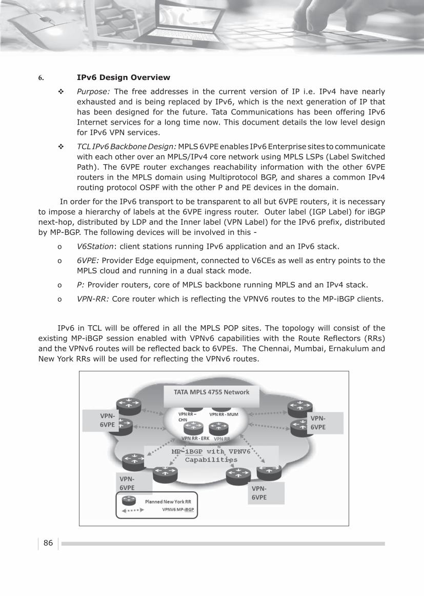
86
6. IPv6 Design Overview
� Purpose: The free addresses in the current version of IP i.e. IPv4 have nearly exhausted and is being replaced by IPv6, which is the next generation of IP that has been designed for the future. Tata Communications has been offering IPv6 Internet services for a long time now. This document details the low level design for IPv6 VPN services.
� TCL IPv6 Backbone Design: MPLS 6VPE enables IPv6 Enterprise sites to communicate with each other over an MPLS/IPv4 core network using MPLS LSPs (Label Switched Path). The 6VPE router exchanges reachability information with the other 6VPE routers in the MPLS domain using Multiprotocol BGP, and shares a common IPv4 routing protocol OSPF with the other P and PE devices in the domain.
In order for the IPv6 transport to be transparent to all but 6VPE routers, it is necessary to impose a hierarchy of labels at the 6VPE ingress router. Outer label (IGP Label) for iBGP next-hop, distributed by LDP and the Inner label (VPN Label) for the IPv6 prefix, distributed by MP-BGP. The following devices will be involved in this -
o V6Station: client stations running IPv6 application and an IPv6 stack.
o 6VPE: Provider Edge equipment, connected to V6CEs as well as entry points to the MPLS cloud and running in a dual stack mode.
o P: Provider routers, core of MPLS backbone running MPLS and an IPv4 stack.
o VPN-RR: Core router which is reflecting the VPNV6 routes to the MP-iBGP clients.
IPv6 in TCL will be offered in all the MPLS POP sites. The topology will consist of the existing MP-iBGP session enabled with VPNv6 capabilities with the Route Reflectors (RRs) and the VPNv6 routes will be reflected back to 6VPEs. The Chennai, Mumbai, Ernakulum and New York RRs will be used for reflecting the VPNv6 routes.

87
6VPEs will be enabled for Dual-Stack routing to support both IPv6 address-family on PE-CE routing and VPNv6 towards the Core with the existing IPv4 and VPNv4 address-families.
� IPv6 Addressing: Increasing the IP address size was one of the main drivers for developing IPv6. IPv6 uses a 128-bit address, which means that we have a maximum of 2¹²8 addresses available. IPv6 addresses are represented as eight 16-bit hexadecimal colon-delimited blocks. TCL will use the Unique Local IPv6 Unicast Address (RFC4193) space FD00::/8 for the addressing of the WAN links. Alternatively customers can also use their own IPv6 addresses for addressing. Unique local addresses are the alternative to the IPv4 private address space.
� IPv6 Addressing Policy: TCL will adopt the following policy for the IPv6 address allocation to the VPN Customers. All the customers subscribing for the IPv6 services will receive a /126 bit address for the WAN segment and the /64 LAN segment will be allocated if customer needs a LAN segment from TCL. Alternately the customer can use his own IP addresses.
� Allocation of IPv6 space in VPN:
SL. No. Locations IPv6 Subnets
1 Wan Link PE-CE FD00::/40
2 TCL Infra/Server Pool FD00:0:01::/40
3 VPN IPv6 Customer LAN FD00:0:02::/40

88
7. Key Points on IPv6 Service Offerings
� PE Router and IOS Support: Cisco 7600 IOS release 12.2(33)SRA or greater and Cisco 7200 IOS 12.2(33)SB or greater.
� CPE Router IOS Support: 15.0M and 15.1T IOS release and above supports IPv6 with multi-VRF capabilities.
� IPv6 VPN will always go along with IPv4 for management. All IPv6 VPN Customers will be dual stacked for management purposes.
� Export/Import map for Extranet VPN and Management would be configured under VRF definition on specific IPv4/IPv6 address-families.
8. IPv6 VPN Troubleshooting Command equivalents
The table below captures the IPv6 VPN troubleshooting commands equivalent to IPv4. All other IGP and LDP related commands will remain same, since MPLS IPv4 backbone is common to IPv6 VPN as well.
IPv4 Commands IPv6 Commands
Show ip vrf interfaces <VRF_Name> Show vrf ipv6 interfaces <VRF_Name>
Show run vrf <VRF_Name> Show run vrf <VRF_Name>
Show ip interface brief Show ipv6 interface brief
Show ip route vrf <VRF_Name> Show ipv6 route vrf <VRF_Name>
Show ip bgp vpnv4 vrf <VRF_Name> summary
Show bgp vpnv6 unicast vrf <VRFName> summary
Show ip cef vrf <VRF_Name> Show ipv6 cef vrf <VRF_Name>
Show bgp vpnv4 unicast Show bgp vpnv6 unicast
ping vrf <VRF_Name> ip <a.b.c.d> source <Interface> repeat <count> size <d_size>
ping vrf <VRF_Name> ipv6 <a.b.c.d>source <Interface> repeat <count> size<d_size>
traceroute vrf <VRF_Name> ip traceroute vrf <VRF_Name> ipv6

89
1. Introduction
When we enter office buildings, hotels, hospitals, retail stores or theatres, we seldom think about how they work. We just expect that they will work and that we will expect to feel comfortable inside. With wireless Sensor networks and new IP protocols, technologies are being developed specifically for IP smart objects such as sensors and actuators used in buildings, factories, cities, etc. Through this concept paper an effort has been made to explain how a building can be converted into a smart building using wireless sensor network and 6lowpan. The details of the components and their availability in the market have been confirmed. The layout of the project has been taken as 18 months.
XIV. Smart Building: A ConceptNTIPRIT
Wireless Sensor Networks (WSN), combined with IPv6 over Low power Wireless Personal Area Networks (6LoWPAN) protocol are becoming the future of embedded internet. Millions of tiny devices connected to the internet are taking pervasive computing to the next level. WSN envisions a seamless integration of day to day commodities with the internet, namely the Internet of Things (IoT). IoT technologies provide an infrastructure for wide range of applications such as industry automation, vehicular ad-hoc sensor networks and smart building systems. Among these, smart building systems are becoming more and more vital due to the improvement they provide to the quality of life.
One of the key components of a smart building system is a WSN, which provides the necessary information to the smart building system, allowing it to control and monitor the physical environment. Without the use of IP protocols, “smart” gateways which are capable of interconnecting different protocols could not be used to overcome the problem of isolation. 6LoWPAN protocol creates the WSN and on top of that the Constrained Application Protocol (CoAP) allows direct and simple interactions with nodes.

90
2. Requirement
Globally many groups are working to showcase the prowess of IPv6 and WSN to convert a building into a smart building. Smart IPv6 building project http://www.smartipv6building.org is one such project which has created the standards for a smart building. The Smart IPv6 Building uses IPv6 as an integrator to enable innovative interactions with and between:
• Building environment
• Information & services
• Human beings
One of the key objectives is to reduce the building energy consumption and CO2 emissions through a more integrated and smarter building management. Areas of interest include:
Building Automation
• To reduce energy consumption by at least 25%.
• To ease the deployment and integration of building automation systems.
• To manage access control and to improve security.
• To provide innovative tools for meeting and conference rooms.
• To develop innovative interfaces within the building (virtual assistant, etc.).
• To enable individual environment customization by the users (temperature, light, music, etc.).
Information & Services
• To display real time information on the state of the world: key fi gures (population, surface of forest, etc.), satellite images, global temperature, etc.
• To provide innovative services, including contextualized services.
• To enable building infrastructure booking (meeting rooms, etc.).
• To ease resource identifi cation and orientation for the delegates attending international conferences.
• To test innovative semantic and multilingual services.
Human Beings
• To provide telepresence solutions
• To facilitate the networking among delegates.
• To develop a global network of delegates & experts, with new forms of decentralized cooperation and collective intelligence.
• To test on-line collaborative tools.
• To organize social activities during the conferences.

91
3. Business Case
The internet and significant price reductions on IT components such as wireless sensors have made smart-building technologies much more affordable, creating a strong business case for owners and investors to invest in smart technologies and building performance.
Smart building technology investments typically pay for themselves within one or two years by delivering energy savings and maintenance efficiencies. In large buildings with centralized building automation systems, relatively inexpensive devices can be connected to the building control panel to enable a smart building management system to extract and analyze real-time equipment and system performance data and use it to fine-tune building performance. These sensors collect data generated by building equipment, from fan blades to chillers.
6LoWPAN is another advance that makes smart building management systems financially feasible to a degree not previously possible. A smart building management system can transmit data generated from hundreds of buildings to a single “command center,” where facilities professionals use complex automated algorithms to monitor equipment performance.
4. Project
In this concept project, a building with two floors consisting of 20000 sq ft on each floor is taken for deploying 6LoWPAN protocol for communication of constrained embedded devices together with CoAP converting it into smart building.
In general a wireless sensor network will be based on a two tiered architecture. One contains sensing nodes or sensors and the other contains the base station node. In this case the sensing node periodically monitors the pre defined physical parameters and sends the data thus gathered to the base station (Figure-1 & Figure-2 of Annexure-I). The base station could be a mote or some other device communicating to the outer world thru an edge router. Sensing node and base station could be two different devices or can be embedded into one. TelosB Mote (Figure-3 of Annexure-I) is one such device which consists of a radio transceiver chip, microcontroller, sensors and expansion connectors. TinyOS is used as the open source component based software development platform. TelosB Motes are easily available which have many different practical applications including temperature, humidity and light sensors.
TelosB uses 802.15.4 standard for link layer connectivity, while in the Internet layer the IPv6 – 6LoWPAN protocol is used. In the transport layer the UDP protocol is used while in the application layer, the CoAP protocol is used.
The details of the lights, ACs door closers and IP cameras which are used to create a WSN thru which performance and security of the building is monitored and controlled are as follows:
• 40000 sq ft area,
• 2 fl oors,
• 160 ACs
• 400 light points (Figure-7 of Annexure-I)

92
• 60 doors ( Entry points to the rooms)
• 40 IP Camera (Figure-6 of Annexure-I)
• 16 Mbps Internet lease line connectivity
It is assumed that the building is already having a Local Area Network connected to Internet and WSN & IP cameras are an addendum to the existing network (Figure-4 of Annexure-I). The tentative floor schematic of the building showing the placement of different nodes is shown in Figure 5 of Annexure –I.
Layer by layer approach of the project is as follows:
• Wireless connectivity: The main characteristics of the 802.15.4 protocol are its low power consumption, support for low latency devices, dynamic device addressing and very low complexity. Data rates are available at 20 kb/s, 40kb/s and 250 kb/s.
• 6LoWPAN: 6LoWPAN is the effi cient extension of IPv6 into the wireless embedded domain, thus enabling end-to-end IP networking and features for a wide range of embedded applications. Issues such as power and duty cycle, multicast communications, mesh topologies, bandwidth and frame size have been extensively addressed.
• UDP: The UDP protocol is used in between of the 6LoWPAN and the CoAP protocol in the transportation layer. It uses a simple transmission model avoiding a big overhead. Error correction mechanisms are used in other layers to ensure correct delivery of packets.
• CoAP: The CoAP application protocol which runs on top of UDP layer is designed to easily translate to HTTP for simple integration with the web. Its main characteristics are constrained machine-to-machine web protocol, simple proxy and caching capabilities, low header overhead and parsing complexity, and reliable unicast and multicast support.
The tentative requirement of sensors and integrators and its price is as under -
S.N Components Quantity Price/piece in Rs Price in Rs
1 Edge Router 4 150000 600000
2 Wireless LAN controller 5 65000 325000
3 7” Touch Screen 18 20000 360000
4 LED Lights 400 1500 600000
5 LED Lighting switches 400 700 280000
9 Cable Package 5 10000 50000
10 IPv6 enabled CCTV Camera 40 18000 720000
11 6Lowpan Nodes 650 6000 3900000
12 CoAP Server 1 500000 500000
Total 7335000
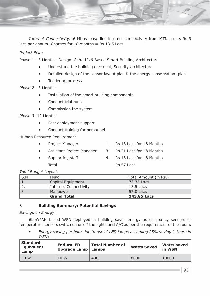
93
Internet Connectivity:16 Mbps lease line internet connectivity from MTNL costs Rs 9 lacs per annum. Charges for 18 months = Rs 13.5 Lacs
Project Plan:
Phase 1: 3 Months- Design of the IPv6 Based Smart Building Architecture
• Understand the building electrical, Security architecture
• Detailed design of the sensor layout plan & the energy conservation plan
• Tendering process
Phase 2: 3 Months
• Installation of the smart building components
• Conduct trial runs
• Commission the system
Phase 3: 12 Months
• Post deployment support
• Conduct training for personnel
Human Resource Requirement:
• Project Manager 1 Rs 18 Lacs for 18 Months
• Assistant Project Manager 3 Rs 21 Lacs for 18 Months
• Supporting staff 4 Rs 18 Lacs for 18 Months
Total Rs 57 Lacs
Total Budget Layout:S.N Head Total Amount (in Rs.)1 Capital Equipment 73.35 Lacs2. Internet Connectivity 13.5 Lacs3 Manpower 57.0 Lacs
Grand Total 143.85 Lacs
5. Building Summary: Potential Savings
Savings on Energy:
6LoWPAN based WSN deployed in building saves energy as occupancy sensors or temperature sensors switch on or off the lights and A/C as per the requirement of the room.
• Energy saving per hour due to use of LED lamps assuming 25% saving is there in WSN:
Standard Equivalent Lamp
EnduraLED Upgrade Lamp
Total Number of Lamps Watts Saved Watts saved
in WSN
30 W 10 W 400 8000 10000

94
• Energy saving per hour in AC assuming 20% saving is there in WSN:
o 1.5 Ton AC draws 2 KWh
o 160 * 2 KW = 320 KWh
o Saving in a WSN = 320 * .2 = 64 KWh or 64 Units.
• Assuming 8 Hrs a day and 5 days a week , energy saving in a year:
o 74 * 8 * 5 * 52 = 153920 Units
o Savings in terms of money , assuming Rs 8/- per unit = 153920 * 8 = Rs 1231360/-
Saving on Security:
IP based CCTV surveillance provides round the clock security anywhere, anytime. The security guards on different floors making rounds and keeping a check on different parts of the building become redundant.
• Assuming 2 guards round the clock on each floor: 12 guards
o Salary of one guard = Rs 15000/- per month
o Total expenditure on security guards = 15000 * 12 * 12 = Rs 2160000 /-
o With CCTV surveillance one guard round the clock = 15000 * 3 * 12 = Rs 540000/-
o Total saving on security = Rs 1620000/-
Gross saving per annum = Rs 2851360/-
• Annual Recurring cost will have two components:
o Maintenance cost of WSN: WSN nodes have low maintenance cost. 5 % maintenance cost will be reasonably good estimate:73.35 * .05 = Rs 366750/-
o Internet Lease Line cost : This cost is taken as Rs 9 Lacs per annum
Gross Annual Recurring Cost: Rs 1266750/-
Besides savings as shown above, CO2 emission of the buildings will be reduced and the building will be under surveillance from anywhere, any time.
6. Conclusion
The project promises a highly energy efficient and secured building whose performance parameters are available anywhere, anytime. RoI of the project is calculated as 18 % .The global market is in the nascent stage and waking up to the demand pouring in from all the corners. The biggest challenge is the non-availability of the components in Indian market (a list of some of the items available in Indian market is at Annexure-II) but instead of taking

95
it as a deterrent, it should be seen as an opportunity for Indian manufacturers and the system integrators as India provides a huge market. With demand going up and Indian manufacturers coming into the forefront, it is expected that the component cost of the project will come down to 25 % of equipment cost making the project much more lucrative. All the calculations shown in this paper are of a typical deployment of WSN in a building, however it is to be noted that the energy savings may differ from case to case depending on the building layout & the planning of the facilities in the building.
7. References
[1] http://www.smartipv6building.org/
[2] http://www.dlink.co.in/
[3] http://www.phillips.com
[4] http://www.nxp.com
[5] http://www.advanticsys.com
[6] http://www.cisco.com
[7] http://www.memsic.com/wireless-sensor-networks
[8] http://www.profilesystems.com/
[9] http://www.xbow.com/

96
Annexure I
Details of Wireless Sensors, Switches & Its Connectivity
Figure-1: This picture explains how sensors interact with switches which in turn are IP based and information can be further taken to remote locations.
Figure-2: Profile System P1902 is one such product which interacts with sensors over wireless connectivity and based on information received from sensors the controller takes decisions about switching on /off the lights/ ACs etc. It can control upto four different blocks simultaneous.

97
Figure-3: TelosB Mote
TelosB Mote
Figure-4: Network Architecture

98
Floor schematic Diagram showing LED Lamp, CCTV, AC and Doors
Figure-5: The fl oor schematic gives details of offi ces, meeting rooms, conference halls etc and suggests how LED lamps with wireless switches, ACs with wireless thermostats,
Doors with IP based locking arrangements can be placed.
Figure -6
Figure -7
DCS 7010L IP Camera
Philips EnduraLED

99
Annexure II
Items taken in the project are not easily available in Indian Market. Some of the items available on internet are shown here. The actual cost in India may be higher than what’s projected here.
Item list
1. Dlink DCS-7010L $300
2. Dimmable Light $20
Philips EnduraLED8W LED bulb
3. Dimmable light driver $10SSL2101T/N1,518
4. WSN Nodes $100TelosB Motes (MTM CM5000)(crossbow )(TPR 2420 Memsic)
5. WSN Development Kit variable based on features (WSN-PRO2110CA Memsic)
6. Cisco CGR1120/k9 $2200
7. Cisco 2504 $800

100
Glossary
SL No Abbreviation Meaning
1 2G 2nd Generation
2 3G 3rd Generation
3 6LoWPAN IPv6 over Low power Wireless Personal Area Networks
4 6VPE IPv6 over MPLS
5 AAA Server Authentication, Authorization and Accounting Server
6 ACL Access Control Lists
7 AFT Address Family Translation
8 ALG Application Level Gateways
9 AMI Advanced Metering Infrastructure
10 AN Autonomous Number
11 ANSI American National Standard Institute
12 APNIC Asia Pacifi c Network Information Centre
13 APP Application
14 APRICOT Asia Pacifi c Regional Internet Conference on Operational Technologies
15 AS Autonomous System
16 ASHRAE American Society of Heating and Air-Conditioning Engineers
17 B2G Building to Grid
18 BCP Business Continuation Plan
19 BGP Border Gateway Protocol
20 BITCOE BSNL IIT Kanpur Telecom Centre of Excellence
21 BSNL Bharat Sanchar Nigam Limited
22 BWA Broadband Wireless Access
23 CAPEX Capital Expenditure
24 CCTLD Country Code Top level Domain
25 CDMA Code Division Multiple Access
26 C-DOT Centre for Development of Telematics

101
27 CERT-In Computer Emergency Response Team India
28 CMS Content Management System
29 CNGI China Next Generation Internet
30 CoAP Constrained Application Protocol
31 CoS Catalogue of Standards
32 COSEM Companion Specifi cation for Energy Metering
33 CSC Common Service Centre
34 CUG Closed User Group
35 DA Distribution Automation
36 DCS Distributed Control Systems
37 DHCP Dynamic Host Confi guration Protocol
38 DLMS Device Language Message Specifi cation
39 DMZ De-Militarized Zone
40 DNS Domain Name System
41 DoT Department of Telecommunications
42 DR Demand-Response
43 DSO Distribution System Operator
44 DST Department of Science & Technology
45 DTLS Datagram Transport Layer Security
46 e-BGP exterior-BGP
47 EMS Enhanced Messaging Service
48 EoL End of Life
49 EoS End of Service
50 ERNET Educational & Research Network
51 EV Electric Vehicle
52 EXI Effi cient XML Interchange
53 G2C Government-to-Citizen
54 GPRS General packet radio service
55 GSWAN Gujarat State Wide Area Network

102
56 GW Gate Way
57 HSDPA High-Speed Downlink Packet Access
58 HSRP Hot Standby Router Protocol
59 HTTP Hyper Text Transfer Protocol
60 HVAC Heating, Ventilation, Air Conditioning
61 i-BGP Interior–BGP
62 ICMP Internet Control Message Protocol
63 ICT Information and Communications Technology
64 IDC Internet Data Center
65 IEC International Electrotechnical Commission
66 IEEE Institute of Electrical and Electronics Engineers
67 IETF Internet Engineering Task Force
68 IIS Internet Information Services
69 IIT Indian Institute of Technology
70 IoT Internet of Things
71 IP Internet Protocol
72 IPDS Interior Procurement Data System
73 IPS In-plane switching
74 IPv4 Internet Protocol version 4
75 IPv6 Internet Protocol version 6
76 IRINN Indian Registry for Internet Names and Numbers
77 ISP Internet Service Provider
78 LDP Label Distribution Protocol
79 LSPs MPLS Label Switched Paths
80 LTE Long Term Evolution
81 M2M Machine to Machine
82 MNC Multi National Corporations
83 MPCTD Madhya Pradesh Commercial Tax Department
84 MPLS Multiprotocol Label Switching

103
85 MPSDC Madhya Pradesh State Data Center
86 MPSEB Madhya Pradesh State Electricity Board
87 MPSEDC Madhya Pradesh State Electronics Development Corporation Ltd
88 MPSWAN Madhya Pradesh State Wide Area Network
89 NAN Neighborhood Area Networks
90 NAT Network Address Translation
91 NAv6 National Advanced IPv6 Centre
92 NeGP National e-Governance Program
93 NIB National Internet Backbone
94 NIC National Informatics Centre
95 NIST National Institute of Standards and Technology
96 NIT National Institute of Technology
97 NKN National Knowledge Network
98 NMS Network Management System
99 NOC Network Operation Centre
100 NTIPRIT National Telecommunication Institute for Policy Research Innovation & Training
101 OEM Original Equipment Manufacturer
102 OMA Open Mobile Alliance
103 OPEX Operating Expenditure
104 OS Operating System
105 OSPF Open Shortest Path First
106 OSPFv2 Open Standard Path First Version 2
107 OSPFv3 Open Standard Path First Version 3
108 OSS Operations support systems
109 OTAP Over-The-Air-Provisioning
110 PE Provider edge
111 PLC Programmable Logic Controllers
112 PoC Proof of Concept
113 PSU Public Sector Units

104
114 QoS Quality of Service
115 RBI Reserve bank of India
116 RFC Request for Comments
117 RFP Request For Proposals
118 RIPENCC Réseaux IP Européens Network Coordination Centre
119 RIR Regional Internet Registry
120 RoI Return on Investment
121 RPL Routing Protocol for Low-Power and Lossy
122 SaaS Software as a service
123 SCADA Supervisory Control And Data Acquisition
124 SDC State Data Centre
125 SDN Software Defi ned Network
126 SGIP Smart Grid Interoperability
127 SLA Service-Level Agreement
128 SLB Server Load Balancer
129 SoIP SCADA over IP
130 SOP Standard Operating Procedure
131 SWAN State Wide Area Network
132 UTM Unifi ed Threat Management
133 VLAN Virtual Local Area Network
134 VPN Virtual Private Network
135 WAN Wide Area Network
136 WBSDC West Bengal State Data Centre
137 WBSWAN West Bengal State Wide Area Network
138 Webel West Bengal Electronics Industry Development Corporation Limited
139 WSN Wireless Sensor Nodes
Related Documents