RASMAG/22−WP17 10-13/07/2017 International Civil Aviation Organization The Twenty-Second Meeting of the Regional Airspace Safety Monitoring Advisory Group (RASMAG/22) Bangkok, Thailand, 10-13 July 2017 Agenda Item 4: Airspace Safety Monitoring Documentation and Regional Guidance Material EMA HANDBOOK AND ICAO DOC 10063 CONTENT COMPARISON (Presented by Australia/AAMA and the United States/PARMO) SUMMARY In anticipation of the availability of the Manual on Monitoring the Application of Performance-Based Horizontal Separation Minima, ICAO Doc 10063, for use as global guidance material, the RASMAG Monitoring Agency Working Group (MAWG) was tasked by RASMAG to compare content of existing guidance material adopted by the Region, the EMA Handbook, to Doc 10063. This paper presents the results of the Enroute Monitoring Agency (EMA) Handbook and ICAO Doc 10063 content comparison performed by the MAWG. Note – This task was performed prior to the publication of the First Edition of Doc 10063, the unedited version was used for the comparison. 1. INTRODUCTION 1.1 During the eighteenth meeting of the Separation and Airspace Safety Panel Meeting of the Working Group of the Whole (SASP/WG/WHL/18) held in November 2010, the need for global guidance material to assist regions with the implementation and maintenance of performance-based re horizontal separation minima was highlighted. The purpose of the global guidance material would be to provide a standardized approach to support and maintain horizontal separation minima which rely on performance-based operations. 1.2 The meeting agreed to the proposed action and assigned the task to SASP Project Team 17 - Safety Assessment Methodologies for the Future ATM Environment. 1.3 The SASP recognized the success achieved in the Asia-Pacific Region where an effective oversight process has been established and processes used are contained in regional guidance manual, The En-route Monitoring Agency Handbook. It was proposed that the material used in the Asia- Pacific region could form the basis for development of a global guidance manual. 1.4 The SASP concluded that steps should be taken to formulate the Asia-Pacific material into more generic language and integrate the processes which exist for safety assessment and analysis of operational errors in other ICAO Regions, such as the North Atlantic Region. 1.5 The work performed by SASP would not seek to mandate new institutional arrangements such as was done with the introduction of the reduced vertical separation minimum (RVSM) and Regional Monitoring Agencies (RMAs). The goal was to provide guidance to groups of States or regions to describe the functionality needed to monitor the safe application of performance-based horizontal separation minima in procedurally controlled airspace. In other words, the manual would not specify how the monitoring functions for applying performance-based horizontal separation minima must be implemented by a group of States or regions. The guidance material would allow for the functionality needed to be contained within a single organization, or assigned to different working groups within the region.

Welcome message from author
This document is posted to help you gain knowledge. Please leave a comment to let me know what you think about it! Share it to your friends and learn new things together.
Transcript
RASMAG/22−WP17
10-13/07/2017
International Civil Aviation Organization
The Twenty-Second Meeting of the Regional Airspace Safety Monitoring
Advisory Group (RASMAG/22)
Bangkok, Thailand, 10-13 July 2017
Agenda Item 4: Airspace Safety Monitoring Documentation and Regional Guidance Material
EMA HANDBOOK AND ICAO DOC 10063 CONTENT COMPARISON
(Presented by Australia/AAMA and the United States/PARMO)
SUMMARY
In anticipation of the availability of the Manual on Monitoring the Application of
Performance-Based Horizontal Separation Minima, ICAO Doc 10063, for use as global
guidance material, the RASMAG Monitoring Agency Working Group (MAWG) was
tasked by RASMAG to compare content of existing guidance material adopted by the
Region, the EMA Handbook, to Doc 10063. This paper presents the results of the Enroute
Monitoring Agency (EMA) Handbook and ICAO Doc 10063 content comparison
performed by the MAWG.
Note – This task was performed prior to the publication of the First Edition of Doc 10063,
the unedited version was used for the comparison.
1. INTRODUCTION
1.1 During the eighteenth meeting of the Separation and Airspace Safety Panel Meeting of
the Working Group of the Whole (SASP/WG/WHL/18) held in November 2010, the need for global
guidance material to assist regions with the implementation and maintenance of performance-based re
horizontal separation minima was highlighted. The purpose of the global guidance material would be
to provide a standardized approach to support and maintain horizontal separation minima which rely
on performance-based operations.
1.2 The meeting agreed to the proposed action and assigned the task to SASP Project Team
17 - Safety Assessment Methodologies for the Future ATM Environment.
1.3 The SASP recognized the success achieved in the Asia-Pacific Region where an effective
oversight process has been established and processes used are contained in regional guidance manual,
The En-route Monitoring Agency Handbook. It was proposed that the material used in the Asia-
Pacific region could form the basis for development of a global guidance manual.
1.4 The SASP concluded that steps should be taken to formulate the Asia-Pacific material
into more generic language and integrate the processes which exist for safety assessment and analysis
of operational errors in other ICAO Regions, such as the North Atlantic Region.
1.5 The work performed by SASP would not seek to mandate new institutional arrangements
such as was done with the introduction of the reduced vertical separation minimum (RVSM) and
Regional Monitoring Agencies (RMAs). The goal was to provide guidance to groups of States or
regions to describe the functionality needed to monitor the safe application of performance-based
horizontal separation minima in procedurally controlled airspace. In other words, the manual would
not specify how the monitoring functions for applying performance-based horizontal separation
minima must be implemented by a group of States or regions. The guidance material would allow for
the functionality needed to be contained within a single organization, or assigned to different working
groups within the region.
RASMAG/22−WP17
10-13/07/2017
2
2. DISCUSSION
2.1 The development of the guidance material which eventually became the Manual on
Monitoring the Application of Performance-Based Horizontal Separation Minima, ICAO Doc 10063,
was completed six years after the project was proposed to SASP. During these six years, many
iterations of the draft document were discussed within SASP. From these useful and practical
exchanges, appropriate modifications were implemented. A few changes of significance include a
detailed description of the role and function of the organization providing horizontal plane monitoring
functions, an emphasis on its essential relationship to the Safety Management Manual as described in
ICAO Doc. 9859, and the connection of maintaining reduced horizontal separation to Annex 19 to the
Convention on Civil Aviation – Safety Management.
2.2 After further review and approval, the first edition of the Manual on Monitoring the
Application of Performance-based Horizontal Separation Minima, ICAO Doc 10063, was published
in 2017.
2.3 In anticipation of the document’s availability for use as global guidance material, the
RASMAG Monitoring Agency Working Group (MAWG) was tasked by the RASMAG to compare
content included in regionally adopted guidance, the EMA Handbook, to Doc 10063. The objective is
to verify that all requirements, functions and practices performed by EMAs established in the Asia--
Pacific Region were encompassed by ICAO Doc 10063. In addition, MAWG was to identify any
material in the EMA Handbook, and not found in ICAO Doc 10063, that still needed to be available
to the Asia-Pacific EMAs.
2.4 The RASMAG MAWG performed a document content comparison and, in summary, it
was determined that ICAO Doc 10063 includes all relevant material contained in the EMA Handbook
with the exception of Appendices A – Flight Information Regions and Responsible En-route
Monitoring Agency and B – States and Designated EMA for the reporting of En-route PBN and Data
Link Approvals.
2.5 Since it is the responsibility of the planning and implementation regional group (PIRG)
to endorse organizations capable of carrying out the duties and responsibilities associated with safety
monitoring, it was determined that each region’s PIRG should maintain this information. In the Asia-
Pacific Region, this information is contained within in the RASMAG report, which includes the
RASMAG List of Competent Airspace Safety Monitoring Organizations in an appendix.
2.6 In addition to the above, the MAWG noted the following overall differences between the
two documents.
ICAO Doc 10063 is more general in terms of the description of the specific
organization designated to perform the needed functionality, whereas the EMA
Handbook specifically speaks of the establishment of EMAs. However, the
requirements to become an endorsed monitoring organization and perform the
needed functionality are the same in both documents.
ICAO Doc 10063 includes more references to ICAO Annexes and Documents in
the body of the document (in context).
ICAO Doc 10063 is referenced by the Performance-based Communication and
Surveillance (PBCS) Manual, ICAO Doc 9869 second edition 2016.
ICAO Doc 10063 addresses the monitoring of Communication, Navigation and
Surveillance performance and approvals whereas the EMA Handbook addresses
monitoring navigation and horizontal-plane performance; these differences are
due to the document dates (August 2010 for the EMA Handbook version 2) and
the advancement of PBCS that has taken place since the EMA Handbook was
drafted.
RASMAG/22−WP17
10-13/07/2017
3
The EMA Handbook addresses Data Link performance monitoring where ICAO
Doc 10063 addresses monitoring automatic dependent surveillance – contract
(ADS-C) and controller pilot data link communication (CPDLC) performance;
this is due to changes that have taken place since the EMA Handbook was
drafted.
2.7 A more detailed line-by-line comparisons are included in Attachments A and B to this
working paper. Attachment A contains the EMA Handbook with all sections cross referenced to
ICAO Doc 10063. If differences exist between the sections, the cross reference is annotated. Content
included in the EMA Handbook, but not included in ICAO Doc 10063, is highlighted in yellow.
Attachment B contains ICAO Doc 10063 with all sections cross referenced to the EMA Handbook. If
differences exist between the sections, the cross reference is annotated. Content included in ICAO
Doc 10063, but not included in the EMA Handbook, is highlighted in yellow. Attachment C contains
an itemization of all differences.
2.8 In conclusion, it was determined that:
The majority of the differences between the EMA Handbook and ICAO Doc
10063 are due to due to changes that have taken place since the EMA Handbook
was drafted and an attempt to generalize terms for global standardization.
ICAO Doc 10063 is more comprehensive than the EMA Handbook; all
necessary content in the EMA Handbook is included in ICAO Doc 10063.
ICAO Doc 10063 contains more references to ICAO Annexes, Standards and
Recommended Practices and guidance material where applicable.
ICAO Doc 10063 is referenced by Performance-based Communication and
Surveillance (PBCS) Manual, ICAO Doc 9869 second edition 2016
ICAO Doc 10063 could replace the EMA Handbook as guidance on
implementation and maintenance of horizontal performance-based separation
standards.
2.9 Therefore, the following Draft Conclusion is submitted for RASMAG’s consideration:
Draft Conclusion/Decision RASMAG/22-X: EMA Handbook and ICAO Doc 10063 Content
What: Organizations performing horizontal plane
performance monitoring in the Asia/Pacific Region should adopt the
Manual on Monitoring the Application of Performance-based
Horizontal Separation Minima, ICAO Doc 10063, as guidance
material, and replace the EMA Handbook with ICAO Doc 10063.
Expected impact:
☐ Political / Global
☒ Inter-regional
☐ Economic
☐ Environmental
☐ Ops/Technical
Why: The majority of the differences between the EMA
Handbook and ICAO Doc 10063 are due to changes taken place
since the EMA Handbook was drafted and an attempt to generalize
terms for global standardization. ICAO Doc 10063 is more
comprehensive than the EMA Handbook, and ICAO Doc 10063
contains more references to ICAO Annexes, Standards and
Recommended Practices and guidance material where applicable.
Follow-up: ☐Required
from States
When: 14-Sep-17 Status: Draft to be
adopted by Subgroup
Who: ☒Sub groups ☒APAC States ☐ICAO APAC RO ☒ICAO HQ ☐Other:

RASMAG/22−WP17
10-13/07/2017
4
3. ACTION BY THE MEETING
3.1 The meeting is invited to:
a) note the information contained in this paper; and
b) endorse the actions included in paragraph 2.7; and
c) discuss the Draft Conclusion at paragraph 2.9.
………………………….
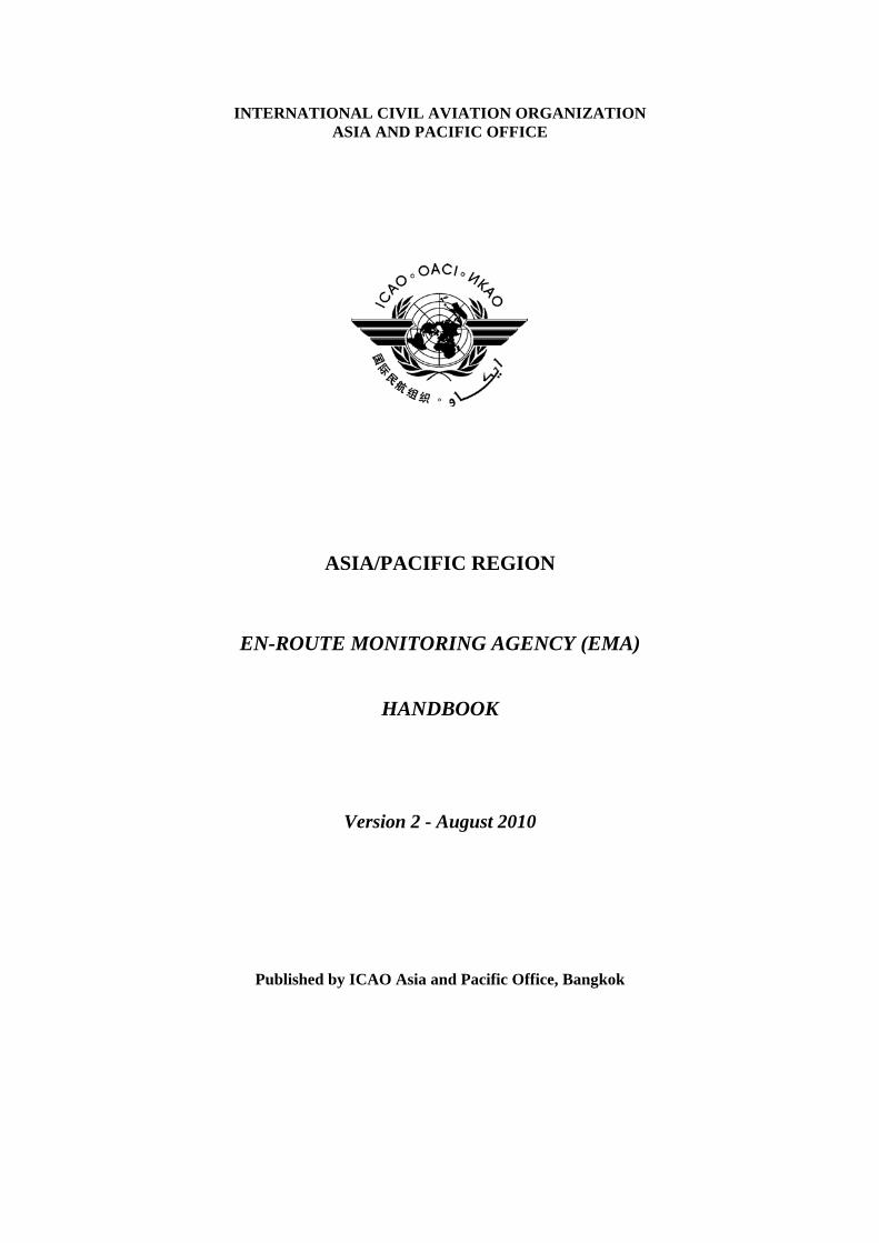
INTERNATIONAL CIVIL AVIATION ORGANIZATION ASIA AND PACIFIC OFFICE
ASIA/PACIFIC REGION
EN-ROUTE MONITORING AGENCY (EMA)
HANDBOOK
Version 2 - August 2010
Published by ICAO Asia and Pacific Office, Bangkok
i
TABLE OF CONTENTS
Table of Contents .................................................................................................................................... i Foreword ............................................................................................................................................... iii List of Abbreviations and Acronyms ..................................................................................................... v Explanation of Terms ............................................................................................................................ vi PART 1 1. Description, Functions and Establishment of an En-route Monitoring Agency........................... 1
1.1 Description.......................................................................................................................... 1 1.2 EMA Duties and Responsibilities....................................................................................... 1 1.3 Process for Establishing an EMA ....................................................................................... 2
PART 2 2. Responsibilities and Standardized Practices of En-route Monitoring Agencies .......................... 3
2.1 Purpose of this Part............................................................................................................. 3 2.2 Establishment and Maintenance of database of PBN and other Approvals........................ 3 2.3 Monitoring of Horizontal Plane Navigation Performance.................................................. 4 2.4 Conducting Safety Assessments and Reporting Results..................................................... 5 2.5 Monitoring Operator Compliance with State Approval Requirements .............................. 8 2.6 Remedial Actions ............................................................................................................... 9 2.7 Review of Operational Concept.......................................................................................... 9
LIST OF APPENDICES Appendix A – Flight Information Regions and Responsible En-Route Monitoring
Agency .................................................................................................................... 10 Appendix B – States and Designated EMA for the Reporting of En-route PBN
and Data Link Approvals ........................................................................................ 11 Appendix C – EMA Forms for Use in obtaining Record of En-route PBN and
Data Link Approvals from a State Authority.......................................................... 12 Appendix D – Minimal Informational Content for each State En-route PBN and
Data Link Approval to be maintained in Electronic Form by an EMA........................................................................................................................ 18
Appendix E – Suggested Form for ATC Unit Monthly Report of Large Lateral
Deviations or Large Longitudinal Errors ................................................................ 27 Appendix F – Example “Know Your Airspace” analysis: Examination of
Operations conducted on South China Sea – RNAV Routes L642 and M771 ................................................................................................................ 33
Appendix G – Example Safety Assessment: South China Sea Collision Risk
Model and Safety Assessment ................................................................................ 39

ii
Appendix H – Sample content and Format for Collection of Sample of Traffic Movements.............................................................................................................. 53
Appendix I – Monitoring Operator Compliance with State Approval
Requirements Flow Chart ....................................................................................... 54 Appendix J – Letter to State Authority requesting Clarification of the Approval
State En-route PBN or Data Link Approval Status of an Operator ........................ 55 Appendix K – Scrutiny Group Guidance ....................................................................................... 56 Appendix L – Pre/Post-Implementation Reduced Horizontal Separation Minima
Flow Chart .............................................................................................................. 58
iii
FOREWORD
The Regional Airspace Safety Monitoring Advisory Group (RASMAG) was established during 2004 by the Asia/Pacific Air Navigation Planning and Implementation Regional Group (APANPIRG) to achieve a regional approach for coordination and harmonization of airspace safety monitoring activities, and to provide assistance to States in this respect. The RASMAG noted that requirements for monitoring aircraft height-keeping performance and the safety of reduced vertical separation minimum (RVSM) operations had been more comprehensively developed than had requirements for monitoring other air traffic management (ATM) services, such as reduced horizontal separation based on performance based navigation (PBN), or for monitoring of air traffic services (ATS) data link systems. Although a handbook with detailed global guidance on the requirements for establishing and operating RVSM Regional Monitoring Agencies (RMA) had been developed by the ICAO Separation and Airspace Safety Panel (SASP), there was no comparable monitoring guidance document under development by ICAO for the safe use of a horizontal-plane separation minimum where PBN is applied and no suitable regional equivalent was available. ICAO provisions require that the implementation of specified reduced separation minima, e.g. 50 NM lateral separation based on PBN RNAV 10, 50 NM longitudinal separation based on PBN RNAV 10 and Direct Pilot Controller Communication (DCPC), and PBN RNP 4 based 30 NM lateral and longitudinal separation based on Automatic Dependent Surveillance – Contract (ADS-C), Controller Pilot Data Link Communication (CPDLC), must first meet Annex 11 safety management system requirements and undergo a safety assessment based on collision risk modelling to confirm that the regionally established target level of safety (TLS) for the airspace has been met. Additionally, periodic safety reviews must be performed in order to permit continued operations. To date, the performance of safety assessments and continued monitoring for reduced horizontal separation minima had been carried out by a few specialized teams of technical experts and contractors supporting States within the region. The recent inclusion of the previously independent RNP and RNAV concepts under ICAO’s global PBN concept has led to some uncertainty amongst States regarding the monitoring requirements for reduced horizontal separation minima implementations where these minima are based on PBN approvals. The RASMAG agreed that there was a need to develop a handbook aimed at standardizing the principles and practices of the work of En-route Monitoring Agencies (EMAs) established to assess the safety performance of implementations utilizing reduced horizontal plane separations, in order to ensure the continued safe application of reduced horizontal separation standards in international airspace. In anticipation of more widespread use of the PBN RNAV 10 and RNP 4 navigation specifications within the international airspace of the Asia/Pacific Region, this handbook is being provided to identify the safety assessment and monitoring requirements and related EMA duties and responsibilities associated with those navigation specifications, as well as the reduced separation minima which may be implemented based upon compliance with them. It should be noted that, with the exception of 50 NM lateral separation, introduction of the reduced horizontal minima additionally necessitates satisfaction of explicit communications and surveillance requirements as well as the navigation performance requirements.
iv
The EMA Handbook is presented in two parts. Part 1 defines an EMA, describes its functions by means of a list of duties and responsibilities, and identifies the process by which an organization gains credentials as an EMA. Part 2 provides specific guidance to assist an EMA in carrying out the duties and responsibilities called for by Part 1. APANPIRG has adopted this EMA Handbook under the terms of Conclusion 20/25 as an Asia/Pacific regional guidance material. It is intended that the handbook will introduce a common set of principles and practices for safety assessment and ongoing safety monitoring in connection with operational usage of reduced horizontal-plane separation minima based on the application of PBN. The handbook will also help to promote an interchange of information among Asia/Pacific States in support of achieving common operational monitoring procedures, as well as supporting the acquisition and sharing of data resulting from the application of those procedures.
v
LIST OF ABBREVIATIONS AND ACRONYMS
ADS-C Automatic Dependent Surveillance - Contract
ANSP Air Navigation Service Provider
APANPIRG Asia Pacific Air Navigation Planning and Implementation Regional Group
ATC Air Traffic Control
ATM Air Traffic Management
ATS Air Traffic Services
CPDLC Controller Pilot Data Link Communication
CRM Collision Risk Model
EMA En-route Monitoring Agency
FIR Flight Information Region
FTP File Transfer Protocol
ICAO International Civil Aviation Organization
LLD Large Lateral Deviation
LLE Large Longitudinal Error
MASPS Minimum Aviation System Performance Standard
NM Nautical Miles
PBN Performance-Based Navigation
RASMAG Regional Airspace Safety Monitoring Advisory Group of APANPIRG
RMA Regional Monitoring Agency
RNAV Area navigation
RNP Required Navigation Performance
RVSM Reduced Vertical Separation Minimum
SASP Separation and Airspace Safety Panel
SSR Secondary Surveillance Radar
STC Supplemental Type Certificate
TLS Target Level of Safety
vi
EXPLANATION OF TERMS
Collision risk. The expected number of mid-air collisions in a prescribed volume of airspace for a specific number of flight hours due to loss of planned separation. (Note: One collision is considered to produce two accidents.)
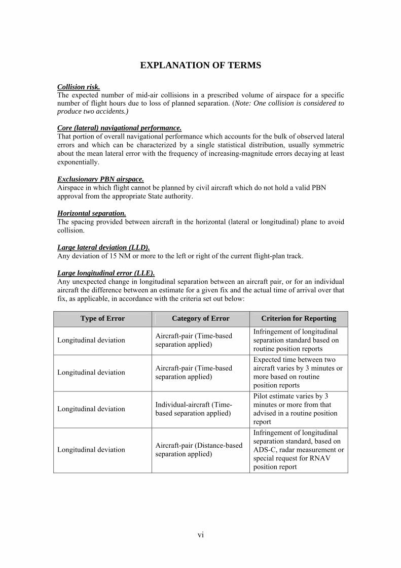
Core (lateral) navigational performance. That portion of overall navigational performance which accounts for the bulk of observed lateral errors and which can be characterized by a single statistical distribution, usually symmetric about the mean lateral error with the frequency of increasing-magnitude errors decaying at least exponentially. Exclusionary PBN airspace. Airspace in which flight cannot be planned by civil aircraft which do not hold a valid PBN approval from the appropriate State authority. Horizontal separation. The spacing provided between aircraft in the horizontal (lateral or longitudinal) plane to avoid collision. Large lateral deviation (LLD). Any deviation of 15 NM or more to the left or right of the current flight-plan track. Large longitudinal error (LLE). Any unexpected change in longitudinal separation between an aircraft pair, or for an individual aircraft the difference between an estimate for a given fix and the actual time of arrival over that fix, as applicable, in accordance with the criteria set out below:
Type of Error Category of Error Criterion for Reporting
Longitudinal deviation Aircraft-pair (Time-based separation applied)
Infringement of longitudinal separation standard based on routine position reports
Longitudinal deviation Aircraft-pair (Time-based separation applied)
Expected time between two aircraft varies by 3 minutes or more based on routine position reports
Longitudinal deviation Individual-aircraft (Time-based separation applied)
Pilot estimate varies by 3 minutes or more from that advised in a routine position report
Longitudinal deviation Aircraft-pair (Distance-based separation applied)
Infringement of longitudinal separation standard, based on ADS-C, radar measurement or special request for RNAV position report
vii
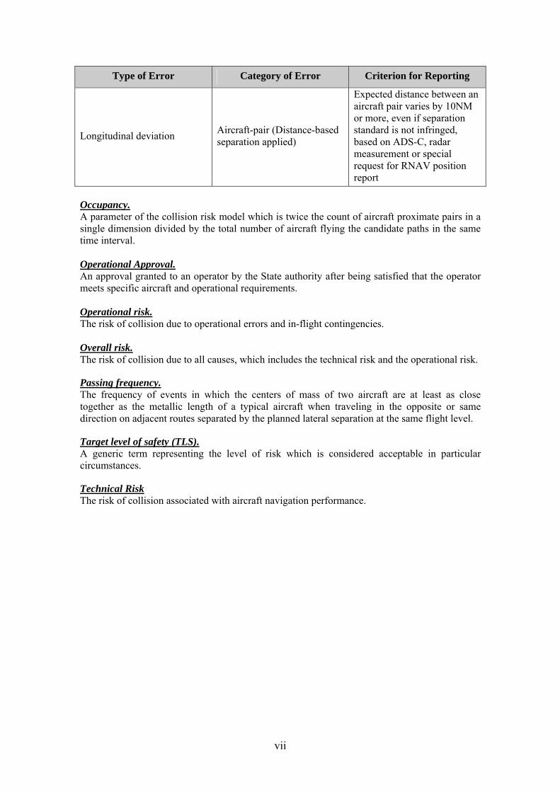
Type of Error Category of Error Criterion for Reporting
Longitudinal deviation Aircraft-pair (Distance-based separation applied)
Expected distance between an aircraft pair varies by 10NM or more, even if separation standard is not infringed, based on ADS-C, radar measurement or special request for RNAV position report
Occupancy. A parameter of the collision risk model which is twice the count of aircraft proximate pairs in a single dimension divided by the total number of aircraft flying the candidate paths in the same time interval. Operational Approval. An approval granted to an operator by the State authority after being satisfied that the operator meets specific aircraft and operational requirements. Operational risk. The risk of collision due to operational errors and in-flight contingencies. Overall risk. The risk of collision due to all causes, which includes the technical risk and the operational risk.
Passing frequency. The frequency of events in which the centers of mass of two aircraft are at least as close together as the metallic length of a typical aircraft when traveling in the opposite or same direction on adjacent routes separated by the planned lateral separation at the same flight level.
Target level of safety (TLS). A generic term representing the level of risk which is considered acceptable in particular circumstances.
Technical Risk The risk of collision associated with aircraft navigation performance.
Asia/Pacific EMA Handbook – Version 2.0, August 2010 1
PART 1
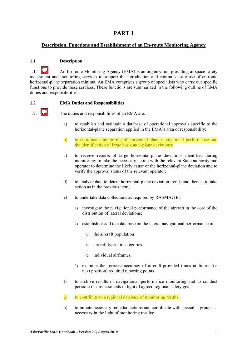
Description, Functions and Establishment of an En-route Monitoring Agency 1.1 Description 1.1.1 An En-route Monitoring Agency (EMA) is an organization providing airspace safety assessment and monitoring services to support the introduction and continued safe use of en-route horizontal-plane separation minima. An EMA comprises a group of specialists who carry out specific functions to provide these services. These functions are summarized in the following outline of EMA duties and responsibilities. 1.2 EMA Duties and Responsibilities 1.2.1 The duties and responsibilities of an EMA are:
a) to establish and maintain a database of operational approvals specific to the horizontal-plane separation applied in the EMA’s area of responsibility;
b) to coordinate monitoring of horizontal-plane navigational performance and
the identification of large horizontal-plane deviations; c) to receive reports of large horizontal-plane deviations identified during
monitoring; to take the necessary action with the relevant State authority and operator to determine the likely cause of the horizontal-plane deviation and to verify the approval status of the relevant operator;
d) to analyze data to detect horizontal-plane deviation trends and, hence, to take
action as in the previous item; e) to undertake data collections as required by RASMAG to:
1) investigate the navigational performance of the aircraft in the core of the distribution of lateral deviations;
2) establish or add to a database on the lateral navigational performance of:
o the aircraft population o aircraft types or categories o individual airframes;
3) examine the forecast accuracy of aircraft-provided times at future (i.e
next position) required reporting points f) to archive results of navigational performance monitoring and to conduct
periodic risk assessments in light of agreed regional safety goals; g) to contribute to a regional database of monitoring results; h) to initiate necessary remedial actions and coordinate with specialist groups as
necessary in the light of monitoring results;
Stephanie.Beritsky
Sticky Note
2.1.1
Stephanie.Beritsky
Sticky Note
2.2.1 b) to coordinate monitoring of horizontal-plane navigational performance and the identification of large horizontal-plane deviations;" is not included in ICAO Doc 10063 "e) 3) examine the forecast accuracy of aircraft-provided times at future (i.e next position) required reporting points" compared to "2.2.1 c) 4) determine the appropriate method to monitor longitudinal errors;" in ICAO Doc 10063 "1.2.1. g) to contribute to a regional database of monitoring results;" not included in ICAO Doc 10063
Stephanie.Beritsky
Highlight
Stephanie.Beritsky
Highlight
Stephanie.Beritsky
Highlight
Stephanie.Beritsky
Highlight
Asia/Pacific EMA Handbook – Version 2.0, August 2010 2
i) to monitor the level of risk as a consequence of operational errors and in-
flight contingencies as follows:
1) determine, wherever possible, the root cause of each horizontal plane deviation together with its size and duration;
2) calculate the frequency of occurrence; 3) assess the overall risk in the system against the overall safety objectives;
and 4) initiate remedial action as required;
j) to initiate checks of the approval status of aircraft operating in the relevant
airspace where horizontal-plane separation is applied, identify non-approved operators and aircraft using the airspace and notify the appropriate State of Registry/State of the Operator accordingly; and
k) to submit reports as required to APANPIRG through RASMAG.
1.3 Process for Establishing an EMA 1.3.1 An organization proposing to offer EMA services must be approved by the Regional Airspace Monitoring Safety Advisory Group of APANPIRG (RASMAG). 1.3.2 In order to effectively carry out the duties and responsibilities of an EMA, an organization must be able to demonstrate an acceptable level of competence. Competence may be demonstrated by:
a) previous monitoring experience; or b) participation in ICAO technical panels or other bodies which develop
horizontal separation requirements or criteria for establishing separation minima based on PBN; or
c) establishment of a formal relationship with an organization qualified under
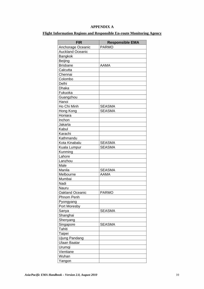
(a) or (b). 1.3.3 Once competence has been demonstrated, including presentation of sufficient material to RASMAG on which to make a reasoned assessment, the EMA should receive a formal approval by RASMAG as recorded in the relevant RASMAG meeting report and in the RASMAG List of Competent Airspace Safety Monitoring Organizations. 1.3.4 Appendix A lists the RASMAG regionally approved EMAs and the Asia/Pacific FIRs for which they hold EMA responsibility.
Stephanie.Beritsky
Sticky Note
2.3.1 Compare to "2.3.1 An organization should perform these functions either locally or on the basis of a bilateral, multilateral or regional air navigation agreement, as applicable, depending on the area of operations." in ICAO Doc 10063
Stephanie.Beritsky
Sticky Note
2.3.2
Stephanie.Beritsky
Sticky Note
2.3.3
Stephanie.Beritsky
Sticky Note
2.3.4
Asia/Pacific EMA Handbook – Version 2.0, August 2010 3
PART 2
Responsibilities and Standardized Practices of En-route Monitoring Agencies 2.1 Purpose of this part 2.1.1 The purpose of this Part of the EMA Handbook is to document experience gained by organizations supporting the introduction of reduced horizontal-plane separation minima within the Asia/Pacific Region, and elsewhere, in order to assist an EMA in fulfilling its responsibilities. Where necessary to ensure standardized practices among EMAs, detailed guidance is elaborated further in appendices. 2.2 Establishment and Maintenance of database of PBN and other Approvals 2.2.1 The experience gained through the introduction of RVSM within Asia/Pacific has shown that the concept of utilising monitoring agencies is essential to ensure safety in the region. Monitoring agencies have a significant role to play in all aspects of the safety monitoring process. One of the functions of an EMA is to establish a database of operators and aircraft or aircraft types approved by State authorities for PBN operations and, if necessary, for use of data link (ADS-C/CPDLC) in the region for which the EMA has responsibility. This information is of vital importance in effectively assessing the risk in the airspace. 2.2.2 Aviation is a global industry; many operators may be approved for PBN and data link operations and their approvals registered with an EMA operating in a region where reduced horizontal separation has been implemented. Thus, there is considerable opportunity for information sharing among EMAs. While a region or sub-region introducing reduced horizontal-plane separation may need its own EMA to act as a focal point for the collection and collation of approvals for aircraft operating solely in that region, it may not need to maintain a complete database of all approved aircraft globally. It will, however, be required to establish links with other EMAs in order to determine the PBN and/or data link status of aircraft. 2.2.3 To avoid duplication by States in registering approvals with EMAs, the concept of a designated EMA for the processing of approval data has been established. Under the designated EMA concept, all States are associated with a specified EMA for the reporting of PBN and data link approvals. Appendix B provides a listing of States and the respective designated EMA for PBN and data link approvals. EMAs may contact any State to address safety matters without regard to the designated EMA for approvals. 2.2.4 It is important to note that, in general, the aircraft operating in airspace where implementation of PBN-based separation is planned can be grouped into two categories. Some aircraft operate solely within the airspace targeted for introduction of reduced separation standards (and therefore may not have PBN and other required approval status) and others operate both within that airspace and other portions of airspace requiring PBN and other approvals. 2.2.5 It is the responsibility of the EMA supporting implementation of reduced separation to gather State approvals data for the former category of aircraft from authorities responsible for issuing those approvals. To do so requires the EMA to establish a communication link with each such State authority and to provide a precise description of the approvals information required. Appendix C provides typical forms, with a brief description of their use, that an EMA might transmit to a State authority to obtain information on aircraft PBN or data link approval status.
Stephanie.Beritsky
Sticky Note
3.1.1
Stephanie.Beritsky
Sticky Note
3.4.1.1 Compare to "3.4.1.1 One of the functions for monitoring the application of performance-based horizontal separation minima is to establish a database of operators and aircraft types/systems approved for performance-based communications (PBC), performance-based navigation (PBN) and performance-based surveillance (PBS) operations by the appropriate authority." in ICAO Doc 10063
Stephanie.Beritsky
Sticky Note
3.4.1.2
Stephanie.Beritsky
Sticky Note
3.4.1.3 Compare "2.2.3 EMAs may contact any State to address safety matters without regard to the designated EMA for approvals." of the EMA Handbook to "3.4.1.3 Designated monitoring organizations should contact the appropriate monitoring organization for a State, to address safety matters for operators registered with that State." in ICAO Doc 10063
Stephanie.Beritsky
Sticky Note
3.4.1.4
Stephanie.Beritsky
Sticky Note
3.4.1.5
Asia/Pacific EMA Handbook – Version 2.0, August 2010 4
2.2.6 To avoid duplication of work effort, wherever possible the EMA should collect State approvals information for the latter category of aircraft – those already operating in other airspace where reduced horizontal-plane separation minima are applied – from other EMAs. This collection will be facilitated if each EMA maintains, in a similar electronic form, a database of State PBN and data link approvals. 2.2.7 Appendix D describes the minimum database content required and the format in which it should be maintained by an EMA. Appendix D also contains a description of the data to be shared by EMAs and proposes procedures for data sharing. 2.3 Monitoring of Horizontal Plane Navigation Performance 2.3.1 An EMA must be prepared to collect the information necessary to monitor horizontal-plane navigational performance as part of the risk assessment. It must institute procedures to monitor core navigational performance and to continuously collect information descriptive of large deviations and operational errors in the horizontal plane.
Monitoring Core Navigational Performance 2.3.2 The EMA will investigate the navigational performance of the aircraft in the core of the distribution of lateral deviations by comparing aircraft reported position information with non-aircraft generated position information such as radar data. The EMA analysis of core navigation performance contributes to the determination of lateral overlap probability used in conducting a safety assessment. An EMA must enlist the cooperation of States and air navigation service providers (ANSPs) in monitoring horizontal-plane core navigational performance through the use of secondary surveillance radar or other appropriate surveillance systems. States and ANSPs have the responsibility to cooperate with the EMA and supply any requested data that will contribute to the evaluation of core navigational performance.
Monitoring of Large Lateral Deviations and Large Longitudinal Errors 2.3.3 Experience has shown that LLDs and LLEs have had significant influence on the outcome of safety assessments before and after implementation of PBN-based separation in a portion of airspace. Accordingly, a principal duty of an EMA is to ensure the existence of a programme to collect this information, assess the occurrences and initiate remedial action to correct systemic problems. Section 2.6 provides guidance to an EMA for initiating such remedial actions as may be necessary to resolve systemic problems uncovered by this programme. One way to ensure the existence of such a programme is to develop letters of agreement between States. 2.3.4 A programme to assess the occurrence of LLDs and LLEs will usually include a regional Scrutiny Group to support the EMA monitoring function. A Scrutiny Group is comprised of operational and technical subject matter experts that support the evaluation and classification of LLDs and LLEs. 2.3.5 Within the airspace for which it is responsible, each ANSP will need to establish the means to detect and report the occurrence of large horizontal-plane deviations. Experience has shown that the primary sources for reports of large horizontal-plane deviations are the ATC units providing air traffic control services in the airspace where reduced separation is or will be applied. The surveillance information available to these units – in the form of voice or ADS-C reports and, where available, surveillance radar or ADS-B returns – provides the basis for identifying large horizontal-plane deviations. 2.3.6 A programme for identifying large horizontal-plane deviations should be established and ATC units should report such events monthly. An example format for these monthly reports is shown in Appendix E. These reports should contain, as a minimum, the following information:
Stephanie.Beritsky
Sticky Note
3.4.1.5 Compare to "3.4.1.5 To avoid duplication of work effort, wherever possible, any regional monitoring organization should collect State approval information from the regional monitoring organization associated with the State of the Operator. This collection will be facilitated if the regional monitoring organization maintains a database of these State approvals in a similar electronic form." of ICAO Doc 10063
Stephanie.Beritsky
Sticky Note
3.4.1.6
Stephanie.Beritsky
Sticky Note
3.4.3.1.1 Compare to "3.4.3.1.1 The monitoring functions include the collection of information necessary to monitor communication, navigational and surveillance performance as part of the risk assessment. Procedures must be instituted to monitor core navigational performance, speed variations, related communication and surveillance performance, and to collect information descriptive of large lateral deviations (LLDs) and large longitudinal errors (LLEs)." of ICAO Doc 10063 - Requirement are more comprehensive in Doc 10063; specifies monitoring C, N and S.
Stephanie.Beritsky
Sticky Note
3.4.3.2.1
Stephanie.Beritsky
Sticky Note
3.4.3.4.1
Stephanie.Beritsky
Sticky Note
3.4.3.4.2
Stephanie.Beritsky
Sticky Note
3.4.3.4.3
Stephanie.Beritsky
Sticky Note
3.4.3.4.5 ICAO Doc 10063 has an additional data requirement, fields 10 and 18 from the ICAO filed flight plan;
Asia/Pacific EMA Handbook – Version 2.0, August 2010 5
a) Reporting unit; b) Location of deviation, either as latitude/longitude, ATS route waypoint or
other ATC fix; c) Date and time of large horizontal-plane deviation; d) Sub-portion of airspace, such as established route system, if applicable; e) Flight identification and aircraft type; f) Actual flight level or altitude; g) Horizontal separation being applied; h) Size of deviation; i) Duration of large deviation; j) Cause of deviation; k) Any other traffic in potential conflict during deviation; l) Crew comments when notified of deviation; and m) Remarks from ATC unit making report.
2.3.7 Other sources for reports of large horizontal-plane deviations should also be explored. An EMA is encouraged to determine if operators within the airspace for which it is responsible are willing to share pertinent summary information from internal safety oversight databases. In addition, an EMA should enquire about access to State databases of safety incident reports which may be pertinent to the airspace. An EMA should also examine voluntary reporting safety databases, where these are available, as possible sources of large horizontal-plane deviations incidents in the airspace for which it is responsible. 2.3.8 While an EMA will be the recipient and archivist for reports of large horizontal-plane deviations, it is important to note that an EMA alone cannot be expected to conduct all activities associated with a comprehensive programme to detect and report large horizontal-plane deviations. Rather, an EMA should enlist the support of RASMAG, the ICAO Regional Office, appropriate implementation task forces, scrutiny groups or any other entity that can assist in the establishment of such a programme. 2.4 Conducting Safety Assessments and Reporting Results
Safety Assessment 2.4.1 In order to conduct a safety assessment, an EMA will need to acquire an in-depth knowledge of the use of the airspace, typical aircraft types etc within which the reduced horizontal-plane separation will be implemented. Experience has shown that such knowledge can be gained through acquisition of charts and other material describing the airspace, and through periodic collection and analysis of samples of traffic movements within the airspace. The collation and consideration of this information results in a “Know Your Airspace” (KYA) analysis that documents matters of relevance to the reduced horizontal separation implementation being proposed. An example of a typical KYA analysis is included as Appendix F. 2.4.2 A safety assessment conducted by an EMA consists of estimating the risk of collision associated with the horizontal-plane separation standard and comparing this risk to the established TLS. Examples of internationally recognised Collision Risk Models (CRMs) used in the development and implementation of reduced separation minima and their application in an example safety assessment (for the South China Sea area) are included in Appendix G of this document and in the ICAO Doc 9689 Manual of Airspace Planning Methodology for the Determination of Separation Minima. 2.4.3 RASMAG will determine the safety reporting requirements (e.g. format and periodicity) for the EMA.
Stephanie.Beritsky
Sticky Note
3.4.4.2.1
Stephanie.Beritsky
Sticky Note
3.4.4.2.2
Stephanie.Beritsky
Sticky Note
3.4.4.2.3
Stephanie.Beritsky
Sticky Note
3.4.3.4.6
Stephanie.Beritsky
Sticky Note
3.4.3.4.7
Asia/Pacific EMA Handbook – Version 2.0, August 2010 6
Establishing the Competence Necessary to Conduct a Safety Assessment
2.4.4 Conducting a safety assessment is a complex task requiring specialized skills which are not practiced widely. As a result, prior to receiving RASMAG approval to operate as an EMA, the organization will need to demonstrate to RASMAG the necessary competence to complete the required tasks. 2.4.5 Ideally, an EMA will have the internal competence to conduct a safety assessment. However, recognizing that personnel with the required skills may not be available internally, an EMA may find it necessary to augment its staff, either through arrangements with another EMA or with an external (i.e. non EMA) organization possessing the necessary competence. 2.4.6 If it is necessary to use an external organization to conduct a safety assessment, an EMA must have the competence to judge that such an assessment is done properly. This competence could be acquired through an arrangement with an EMA which has conducted safety assessments. 2.4.7 An EMA will need to take into account that a safety assessment must reflect the factors which influence collision risk within the airspace where the reduced horizontal-plane separation will be applied. Thus, an EMA will need to establish a method to collect and organize pertinent data and other information descriptive of these airspace factors. As will be noted below, some data sources from other airspace where reduced horizontal-plane separation has been implemented may assist an EMA in conducting a safety assessment. However, an EMA may not use the safety assessment results from another portion of airspace as the sole justification for concluding that the TLS will be met in the airspace where the EMA has safety assessment responsibility.
Assembling a sample of traffic movements from the airspace 2.4.8 Samples of traffic movement data should be collected for the entire airspace where reduced horizontal-plane separation will be implemented. As a result, ANSPs providing services within the airspace are required to cooperate in providing this data. 2.4.9 In planning the timing and duration of a traffic movement data sample, an EMA should take into account the importance of capturing any periods of heavy traffic flow which might result from seasonal or other factors. The duration of any traffic sample should be at least 30 days, with a longer sample period left to the judgment of an EMA. By regional agreement, as recorded in APANPIRG Conclusion 16/4, traffic sample data within the Asia/Pacific Region is collected by all States for the month of December each year for purposes of RVSM monitoring. During 2009, APANPIRG 20 expanded the usage of this data under certain conditions to support regional implementations, including reduced horizontal plane separation minima. 2.4.10 The following information should be collected for each flight in the sample:
a) date of flight; b) flight identification or aircraft call sign, in standard ICAO format; c) aircraft registration mark, if available; d) PBN approval type; e) aircraft type conducting the flight, as listed in the applicable edition of ICAO
Doc 8643, Aircraft Type Designators; f) origin aerodrome, as listed in the applicable edition of ICAO Doc 7910,
Location Indicators; g) destination aerodrome, as listed in the applicable edition of ICAO Doc 7910,
Location Indicators; h) entry point (fix or latitude/longitude) into the airspace; i) time (UTC) at entry point;
Stephanie.Beritsky
Sticky Note
3.4.4.1.1
Stephanie.Beritsky
Sticky Note
3.4.4.1.2
Stephanie.Beritsky
Sticky Note
3.4.4.1.3
Stephanie.Beritsky
Sticky Note
3.2.1
Stephanie.Beritsky
Sticky Note
3.2.2
Stephanie.Beritsky
Sticky Note
3.2.3
Stephanie.Beritsky
Sticky Note
3.2.4 Compare "2.4.7 However, an EMA may not use the safety assessment results from another portion of airspace as the sole justification for concluding that the TLS will be met in the airspace where the EMA has safety assessment responsibility." of the EMA Handbook to "3.2.4 However, these data may not be used as the sole justification for concluding that the TLS will be met in another airspace unless it is determined that the assumptions made in the safety assessment for the other airspace are applicable and valid for the relevant airspace." of ICAO Doc 10063 - ICAO Doc 10063 includes conditional provision for use of safety assessments results from another portion of airspace.
Asia/Pacific EMA Handbook – Version 2.0, August 2010 7
j) flight level (and assigned Mach number if available) at entry point; k) route after entry point; l) exit point from the airspace; m) time (UTC)at exit point; n) flight level (and assigned Mach number if available) at exit point; o) route before exit fix; and p) additional fix/time/flight-level/route combinations that the EMA judges are
necessary to capture the traffic movement characteristics of the airspace. 2.4.11 Where possible, in coordinating collection of the sample, an EMA should specify that information be provided in electronic form (for example, in a spreadsheet). Appendix H contains a sample specification for collection of traffic movement data in electronic form, where the entries in the first column may be used as column headings on a spreadsheet template. 2.4.12 Acceptable sources for the information required in a traffic movement sample could include one or more of the following: ATC observations, ATC automation system data, automated air traffic management system data and secondary surveillance radar (SSR) reports.
Data Link Performance Monitoring 2.4.13 Applications specific to communication systems required for PBN-based operations such as data link introduce operational and technical risk into the system. Therefore end-to-end safety performance monitoring of air-ground and ground-air data link communication services should be ongoing, in accordance with the information contained in the Guidance Material for End-to-End Safety and Performance Monitoring of Air Traffic Service (ATS) Data Link Systems in the Asia/Pacific Region, issued by the ICAO Asia and Pacific Office, Bangkok. In the assessment of risk levels, an EMA may find it necessary to use data link performance data from data link Central Reporting Agencies (CRAs). 2.4.14 In conducting data link monitoring, CRA’s could evaluate the following communication and surveillance performance elements:
a) Position reporting methods and usage; b) Flight plans and data link capabilities; c) ADS-C downlink message traffic; d) ADS-C downlink transit times; e) ADS-C uplink message traffic; f) ADS-C uplink transit and response times; g) Anomalies identified in ADS-C data; h) Uplink messages with no response; i) CPDLC uplink and downlink message traffic, including response times; and j) Communication service provider outages and the effect on data link
performance
Determining whether the Safety Assessment satisfies the TLS 2.4.15 “Technical risk” is the term used to describe the risk of collision associated with aircraft navigation performance. Some of the factors which contribute to technical risk are:
a) errors in aircraft navigation systems; and b) aircraft equipment failures resulting in unmitigated deviation from the cleared
flight path, including those where not following the required procedures further increases the risk.
Stephanie.Beritsky
Sticky Note
3.4.4.1.4
Stephanie.Beritsky
Sticky Note
3.4.4.1.5
Stephanie.Beritsky
Highlight
Stephanie.Beritsky
Sticky Note
3.4.4.3.1 "2.4.15 a) errors in aircraft navigation systems;" of the EMA Handbook compared to "3.4.4.3.1 a) errors in aircraft communication, navigation and surveillance systems;" of ICAO Doc 10063 - ICAO Doc 10063 addresses CNS
Asia/Pacific EMA Handbook – Version 2.0, August 2010 8
2.4.16 “Operational risk” is the term used to describe the risk of collision due to operational errors and in-flight contingencies. The term “operational error” is used to describe any horizontal deviation of an aircraft from the correct flight path as a result of incorrect action by ATC or the flight crew. Examples of such actions include:
a) a flight crew misunderstanding an ATC clearance, resulting in the aircraft
operating on a flight path other than that issued in the clearance; b) ATC issuing a clearance which places an aircraft on a flight path where the
required separation from other aircraft cannot be maintained; c) a coordination failure between ATC units in the transfer of control
responsibility for an aircraft, resulting in either no notification of the transfer or in transfer at an unexpected transfer point;
d) weather deviation (Note: these deviations may be instances where the aircraft
captain initiates the manoeuvre using operational authority but without advising ATC, and are not necessarily deemed as being incorrect action. However, they still contribute to operational risk and should be reported).
2.4.17 The TLS which must be satisfied is established by regional agreement and documented in the Regional Supplementary Procedures (Doc 7030). The generic Asia/Pacific TLS is presently established, for each dimension (lateral, longitudinal and vertical), as 5 x 10⁻⁹ fatal accidents per flight hour due to loss of planned separation; however, specific TLS values may be determined by ICAO for application of a particular separation minimum. 2.5 Monitoring Operator Compliance with State Approval Requirements 2.5.1 The overall intent of post-implementation EMA activities is to support continued safe use of the reduced horizontal-plane separation. One important post-implementation activity is monitoring operator compliance with State approval requirements by carrying out periodic checks of the approval status of operators and aircraft using airspace where PBN-based separation is applied. This is vital if reduced separation is applied on an exclusionary basis, that is, if State PBN and data link approval is a prerequisite for use of the airspace. 2.5.2 An EMA will require two sources of information to monitor operator compliance with State approval requirements: a listing of the operators, and the type and registration marks of aircraft conducting operations in the airspace; and the database of State PBN and data link approvals. 2.5.3 Ideally, this compliance monitoring should be done for the entire airspace on a daily basis. Clearly, difficulties in accessing traffic movement information may make such daily monitoring impossible. However, as a minimum an EMA should conduct compliance monitoring of the complete airspace for at least a 30-day period annually. A flow chart depicting the process required for monitoring operator compliance with State approvals has been included as Appendix I. 2.5.4 When conducting compliance monitoring, the filed PBN or data link approval status shown on the flight plan of each aircraft movement should be compared to the database of State PBN and data link approvals. When a flight plan shows a PBN or data link approval not confirmed in the database, the appropriate State authority should be contacted for clarification of the discrepancy. An EMA should use a letter similar in form to that shown in Appendix J as the official notification. 2.5.5 An EMA should keep in mind that the responsibility to take any action should an operator be found to have filed an incorrect declaration of State PBN or data link approval lies clearly with the State authority, not the EMA. The EMA responsibility is only to make the appropriate State authority aware of the issue, and provide advice or information as requested by the State authority.
Stephanie.Beritsky
Sticky Note
3.4.4.3.2
Stephanie.Beritsky
Sticky Note
3.4.4.3.3
Stephanie.Beritsky
Sticky Note
3.4.2.1
Stephanie.Beritsky
Sticky Note
3.4.2.2 Compare to "3.4.2.2 Two sources of information are needed to perform this monitoring: a) aircraft identification (Item 7), aircraft type (Item 9), aircraft registration and PBC, PBN, and/or PBS capability indicated in Items 10 and 18 of the flight plan; and b) the database of State PBC, PBN, or PBS approval status, which is obtained from the State of the Operator or State of Registry." of ICAO Doc 10063 - 10063 address PBS and PBC approval data
Stephanie.Beritsky
Sticky Note
3.4.2.3
Stephanie.Beritsky
Sticky Note
3.4.2.5
Stephanie.Beritsky
Sticky Note
2.4.2.4 Compare to "3.4.2.4 When a flight plan shows a performance-based operational approval not confirmed in the database, the monitoring organization should officially notify the appropriate organization - The appropriate organization is as follows : a) State of the Operator or State of Registry, as appropriate, if the State is assigned to the designated monitoring organization; or b) the designated monitoring organization to which the State of the Operator or State of Registry is assigned." of ICAO Doc 10063 - ICAO Doc 10063 includes reporting the designated monitoring organization to which the State of the Operator or State of Registry is assigned when an approval not confirmed in the database is detected
Asia/Pacific EMA Handbook – Version 2.0, August 2010 9
2.6 Remedial Actions 2.6.1 Remedial actions are those measures taken to remove causes of systemic problems associated with factors affecting safe use of the PBN-based separation. Remedial actions may be necessary to remove the causes of problems such as the following:
a) failure of an aircraft to comply with PBN or data link requirements, b) aircraft operating practices resulting in large horizontal-plane deviations, and
c) operational errors.
2.6.2 Monitoring results should be periodically reviewed by the EMA and the associated regional Scrutiny Group in order to determine if there is evidence of any recurring problems or adverse trends. Guidance on the functions of a Scrutiny Group is contained in Appendix K. 2.6.3 As a minimum, an EMA and the associated Scrutiny Group should conduct an annual review of reports of large horizontal-plane deviations with a view toward uncovering systemic problems and initiating remedial action. Should such problems be identified, an EMA should report its findings to the body overseeing horizontal-plane separation implementation, or to the RASMAG. An EMA should include in its report the details of large horizontal-plane deviations suggesting the root cause of the problem. 2.7 Review of Operational Concept 2.7.1 Experience has shown that the operational concept for the application of the horizontal-plane separation adopted by bodies overseeing horizontal-plane separation implementations can substantially affect the collision risk in airspace. 2.7.2 An EMA should review carefully the operational concept agreed by the body overseeing horizontal-plane separation implementation, generally the ANSP, with a view to identifying any features of airspace use which may influence risk. The flow chart at Appendix L provides an overview of the implementation process for reduced horizontal plane separation minima and draws attention to the interrelationships between the implementation activities of the ANSP and the safety assessment and monitoring responsibilities of the EMA. An EMA should inform the oversight body of any aspects of the operational concept which it considers important in this respect.
Stephanie.Beritsky
Sticky Note
3.4.4.4.1
Stephanie.Beritsky
Sticky Note
3.4.4.4.2
Stephanie.Beritsky
Sticky Note
3.4.4.4.3
Stephanie.Beritsky
Sticky Note
3.3.1.1
Stephanie.Beritsky
Sticky Note
3.3.1.2
Stephanie.Beritsky
Sticky Note
3.1.3
Asia/Pacific EMA Handbook – Version 2.0, August 2010 10
APPENDIX A
Flight Information Regions and Responsible En-route Monitoring Agency
FIR Responsible EMA Anchorage Oceanic PARMO Auckland Oceanic Bangkok Beijing Brisbane AAMA Calcutta Chennai Colombo Delhi Dhaka Fukuoka Guangzhou Hanoi Ho Chi Minh SEASMA Hong Kong SEASMA Honiara Inchon Jakarta Kabul Karachi Kathmandu Kota Kinabalu SEASMA Kuala Lumpur SEASMA Kunming Lahore Lanzhou Male Manila SEASMA Melbourne AAMA Mumbai Nadi Nauru Oakland Oceanic PARMO Phnom Penh Pyongyang Port Moresby Sanya SEASMA Shanghai Shenyang Singapore SEASMA Tahiti Taipei Ujung Pandang Ulaan Baatar Urumqi Vientiane Wuhan Yangon
Asia/Pacific EMA Handbook – Version 2.0, August 2010 11
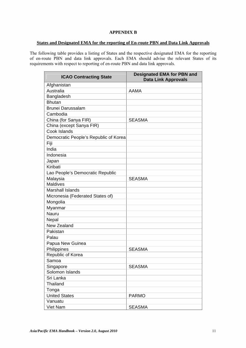
APPENDIX B
States and Designated EMA for the reporting of En-route PBN and Data Link Approvals The following table provides a listing of States and the respective designated EMA for the reporting of en-route PBN and data link approvals. Each EMA should advise the relevant States of its requirements with respect to reporting of en-route PBN and data link approvals.
ICAO Contracting State Designated EMA for PBN and Data Link Approvals
Afghanistan Australia AAMA Bangladesh Bhutan Brunei Darussalam Cambodia China (for Sanya FIR) SEASMA China (except Sanya FIR) Cook Islands Democratic People’s Republic of Korea Fiji India Indonesia Japan Kiribati Lao People’s Democratic Republic Malaysia SEASMA Maldives Marshall Islands Micronesia (Federated States of) Mongolia Myanmar Nauru Nepal New Zealand Pakistan Palau Papua New Guinea Philippines SEASMA Republic of Korea Samoa Singapore SEASMA Solomon Islands Sri Lanka Thailand Tonga United States PARMO Vanuatu Viet Nam SEASMA

Asia/Pacific EMA Handbook – Version 2.0, August 2010 12
APPENDIX C
EMA Forms For Use in Obtaining Records of En-route PBN and Data Link Approvals from a State Authority
There are 3 EMA forms for the collection of essential information relating to en-route PBN and data link approvals:
EMA A1 – Point of Contact Details for Matters Relating to PBN or Data Link Approvals EMA A2 – Record of en-route PBN or Data Link Approval EMA A3 – Withdrawal of en-route PBN or Data Link Approval
1. Please read these notes before attempting to complete forms EMA A1, A2 and A3. 2. It is important for the EMAs to have an accurate record of a point of contact for any queries that
might arise from the monitoring of horizontal-plane separation. Recipients are therefore requested to include a completed EMA A1 with their first reply to the EMA. Thereafter, there is no further requirement unless there has been a change to the information requested on the form.
3. Form EMA A2 must be completed for each operator/aircraft granted a PBN or data link approval. 4. Form EMA A3 must be completed and submitted immediately whenever a State of Registry has
cause to withdraw an operator/aircraft en-route PBN or data link approval. 5. Note: the fields in the forms EMA A2 and EMA A3 should be completed as indicated below.
Fields Instruction State of Registry State of Operator State of PBN Approval
Enter the 2-letter ICAO identifier as contained in ICAO Doc 7910. In the case of there being more than one identifier designated for the State, use the letter identifier that appears first.
Operator Identifier Enter the operator’s 3 letter ICAO identifier as contained in ICAO Doc 8585. For International General Aviation, enter “IGA”. If none, place an X in this field and enter the name of the operator/owner in the Remarks row.
Operator Type Enter or Select Operator Type. E.g. Civil or Military
Registration Date Date of Approval Date of Expiry
Enter date in dd/mm/yyyy format, e.g. for 26 October 2007 enter 26/10/2007.
Aircraft Type Enter the ICAO designator as contained in ICAO Doc 8643, e.g., for Airbus A320-211, enter A320; for Boeing B747-438 enter B744.
Aircraft Series Enter series of aircraft type or manufacturer’s customer designation, e.g., for Airbus A320-211, enter 211; for Boeing B747-438, enter 400 or 438.
Mode S Address Code (Hex)
Enter ICAO allocated Aircraft Mode S address code in hexadecimal format.
PBN Approval Type
Enter or select the type of PBN Approval, e.g. RNP 2, RNP 4, RNAV 10 or Others. Enter new line for each approval type.
Remarks Any Remarks
Stephanie.Beritsky
Sticky Note
Appendix A
Asia/Pacific EMA Handbook – Version 2.0, August 2010 13
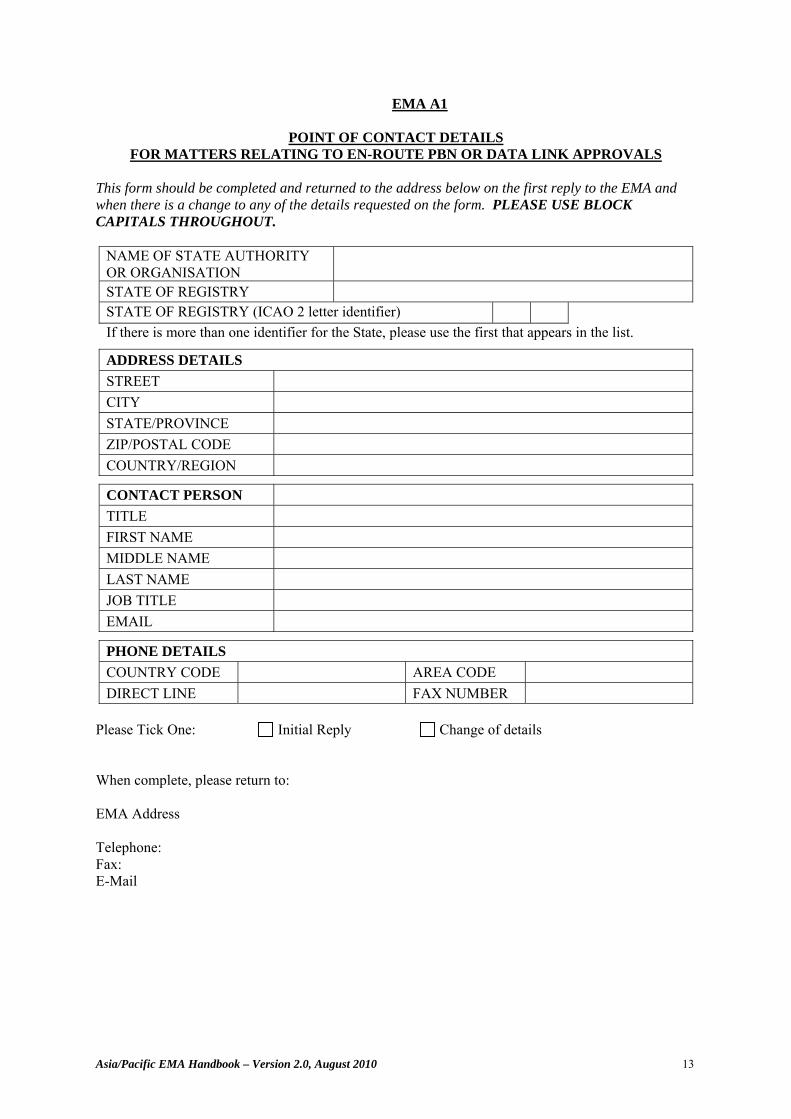
EMA A1
POINT OF CONTACT DETAILS FOR MATTERS RELATING TO EN-ROUTE PBN OR DATA LINK APPROVALS
This form should be completed and returned to the address below on the first reply to the EMA and when there is a change to any of the details requested on the form. PLEASE USE BLOCK CAPITALS THROUGHOUT.
NAME OF STATE AUTHORITY OR ORGANISATION
STATE OF REGISTRY STATE OF REGISTRY (ICAO 2 letter identifier) If there is more than one identifier for the State, please use the first that appears in the list.
ADDRESS DETAILS STREET CITY STATE/PROVINCE ZIP/POSTAL CODE COUNTRY/REGION
CONTACT PERSON TITLE FIRST NAME MIDDLE NAME LAST NAME JOB TITLE EMAIL
PHONE DETAILS COUNTRY CODE AREA CODE DIRECT LINE FAX NUMBER
Please Tick One: Initial Reply Change of details When complete, please return to: EMA Address Telephone: Fax: E-Mail

Asia/Pacific EMA Handbook – Version 2.0, August 2010 14
EMA A2
RECORD OF EN-ROUTE PBN APPROVAL When a State of Registry approves or amends the approval of an operator/aircraft for en-route PBN operations, details of that approval must be recorded and sent to the appropriate EMA without delay. Please refer to the accompanying notes on the following page before providing the information requested below. PLEASE USE BLOCK CAPITALS.
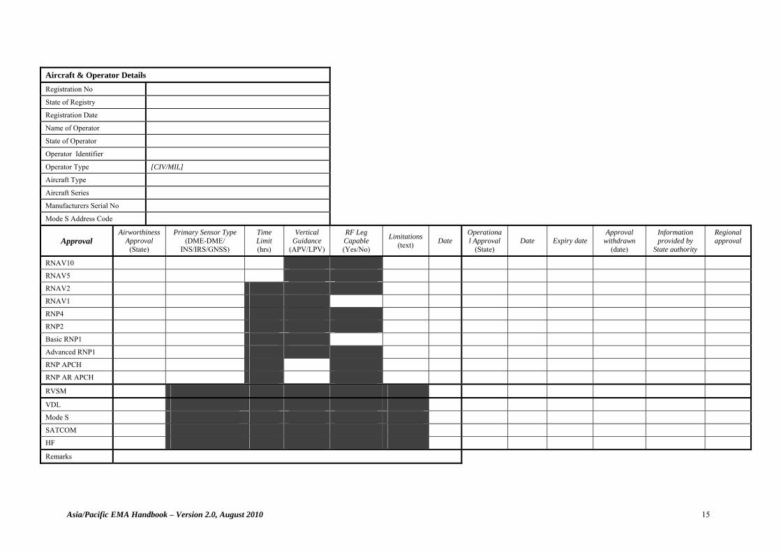
Asia/Pacific EMA Handbook – Version 2.0, August 2010 15
Aircraft & Operator Details Registration No
State of Registry
Registration Date
Name of Operator
State of Operator
Operator Identifier
Operator Type [CIV/MIL]
Aircraft Type
Aircraft Series
Manufacturers Serial No
Mode S Address Code
Approval Airworthiness
Approval (State)
Primary Sensor Type (DME-DME/
INS/IRS/GNSS)
Time Limit (hrs)
Vertical Guidance
(APV/LPV)
RF Leg Capable (Yes/No)
Limitations (text) Date
Operational Approval
(State) Date Expiry date
Approval withdrawn
(date)
Information provided by
State authority
Regional approval
RNAV10
RNAV5
RNAV2
RNAV1
RNP4
RNP2
Basic RNP1
Advanced RNP1
RNP APCH
RNP AR APCH
RVSM
VDL
Mode S
SATCOM
HF
Remarks
Asia/Pacific EMA Handbook – Version 2.0, August 2010 16
When complete, please return to the following address. EMA Address Telephone: Fax: Email:
Asia/Pacific EMA Handbook – Version 2.0, August 2010 17
Fields Instruction State of Registry State of Operator State of PBN Approval
Enter the 2-letter ICAO identifier as contained in ICAO Doc 7910. In the case of there being more than one identifier designated for the State, use the letter identifier that appears first.
Operator Identifier Enter the operator’s 3 letter ICAO identifier as contained in ICAO Doc 8585. For International General Aviation, enter “IGA”. If none, place an X in this field and enter the name of the operator/owner in the Remarks row.
Operator Type Enter or Select Operator Type. E.g. Civil or Military
Registration Date Date of Approval Date of Expiry
Enter date in dd/mm/yyyy format, e.g. for 26 October 2007 enter 26/10/2007.
Aircraft Type Enter the ICAO designator as contained in ICAO Doc 8643, e.g., for Airbus A320-211, enter A320; for Boeing B747-438 enter B744.
Aircraft Series Enter series of aircraft type or manufacturer’s customer designation, e.g., for Airbus A320-211, enter 211; for Boeing B747-438, enter 400 or 438.
Mode S Address Code (Hex)
Enter ICAO allocated Aircraft Mode S address code in hexadecimal format.
PBN Approval Type
Enter or select the type of PBN Approval, e.g. RNP 2, RNP 4, RNAV 10 or Others. Enter new line for each approval type.
Remarks Any Remarks
Asia/Pacific EMA Handbook – Version 2.0, August 2010 18
EMA A3
WITHDRAWAL OF EN-ROUTE PBN OR DATALINK APPROVAL
When a State of Registry has cause to withdraw the en-route PBN or data link approval of an operator/aircraft, the details requested below must be sent to the EMA without delay. Please refer to the accompanying notes on the following page before providing the information requested. PLEASE USE BLOCK CAPITALS.
State of Registry
Operator Identifier
State of Operator
Aircraft Type
Aircraft Series
Manufacturers Serial Number
Registration Mark
Mode S Address Code (Hex)
Approval Withdrawn (PBN or DL)
Date of Withdrawal
PBN Withdrawn CAA Official
Reason for Withdrawal
When complete, please return to the following address. EMA Address Telephone: Fax: Email:
Asia/Pacific EMA Handbook – Version 2.0, August 2010 19
Fields Instruction
State of Registry State of Operator
Enter the 2-letter ICAO identifier as contained in ICAO Doc 7910. In the case of there being more than one identifier designated for the State, use the letter identifier that appears first.
Operator Identifier Enter the operator’s 3 letter ICAO identifier as contained in ICAO Doc 8585. For International General Aviation, enter “IGA”. If none, place an X in this field and enter the name of the operator/owner in the Remarks row.
Date of Withdrawal Enter date in dd/mm/yyyy format, e.g. for 26 October 2007 enter 26/10/2007.
Aircraft Type Enter the ICAO designator as contained in ICAO Doc 8643, e.g., for Airbus A320-211, enter A320; for Boeing B747-438 enter B744.
Aircraft Series Enter series of aircraft type or manufacturer’s customer designation, e.g., for Airbus A320-211, enter 211; for Boeing B747-438, enter 400 or 438.
Mode S Address Code (Hex)
Enter ICAO allocated Aircraft Mode S address code in hexadecimal format.
Approval Withdrawn
Enter or select the type of PBN Approval, e.g. RNP 2, RNP 4, RNAV 10 or Others. Enter new line for each approval type.
Asia/Pacific EMA Handbook – Version 2.0, August 2010 20
APPENDIX D
Minimal Informational Content for Each State En-route PBN or Data Link Approval to Be Maintained In Electronic Form by an EMA
Aircraft PBN and Data Link Approvals Data
To properly maintain and track PBN and data link approval information some basic aircraft identification information is required (e.g., manufacturer, type, serial number, etc.) as well as details specific to an aircraft’s PBN and data link approval status. Table 1 below lists the minimum data fields to be collected by an EMA for an individual aircraft. Table 2 on the following page describes the approvals database record format.
Table 1: Aircraft PBN and Data Link Approvals Data
Field Description Registration Mark Aircraft’s current registration mark
Mode S Address Code (Hex) Aircraft’s current Mode S code 6 hexadecimal digits
Manufacturer Serial Number Aircraft Serial Number as given by manufacturer
Aircraft Type Aircraft Type as defined by ICAO document 8643
Aircraft Series Aircraft generic series as described by the aircraft manufacturer (e.g., 747-100, series = 100)
State of Registry State to which the aircraft is currently registered as defined in ICAO document 7910
Registration Date Date registration was active for current operator
Operator Identifier ICAO code for the current Operator as defined in ICAO document 8585
Operator Name Name of the current Operator
State of Operator State of the current Operator as defined in ICAO document 7910
Operator Type Aircraft is civil or military
PBN approval type PBN approval – e.g. RNP 4, RNAV 2, RNP 1
State of PBN approval State granting PBN approval as defined in ICAO document 9613
Date PBN approved Date of PBN Approval
Date of PBN expiry Date of Expiry for PBN Approval
Date of Data Link approval Date of Data Link Approval
Remarks Open comments
Date of withdrawal of PBN approval Date of withdrawal of the aircraft’s PBN approval (if applicable)
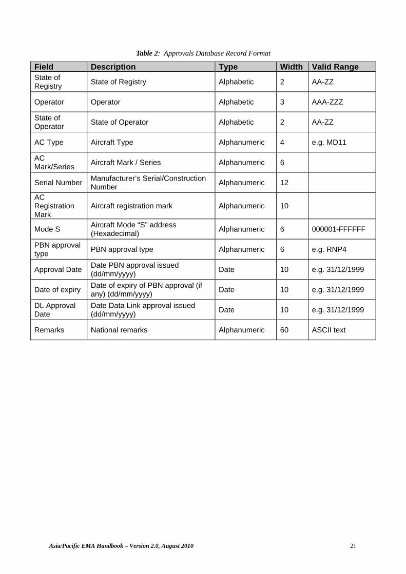
Asia/Pacific EMA Handbook – Version 2.0, August 2010 21
Table 2: Approvals Database Record Format
Field Description Type Width Valid Range State of Registry State of Registry Alphabetic 2 AA-ZZ
Operator Operator Alphabetic 3 AAA-ZZZ
State of Operator State of Operator Alphabetic 2 AA-ZZ
AC Type Aircraft Type Alphanumeric 4 e.g. MD11
AC Mark/Series Aircraft Mark / Series Alphanumeric 6
Serial Number Manufacturer’s Serial/Construction Number Alphanumeric 12
AC Registration Mark
Aircraft registration mark Alphanumeric 10
Mode S Aircraft Mode “S” address (Hexadecimal) Alphanumeric 6 000001-FFFFFF
PBN approval type PBN approval type Alphanumeric 6 e.g. RNP4
Approval Date Date PBN approval issued (dd/mm/yyyy) Date 10 e.g. 31/12/1999
Date of expiry Date of expiry of PBN approval (if any) (dd/mm/yyyy) Date 10 e.g. 31/12/1999
DL Approval Date
Date Data Link approval issued (dd/mm/yyyy) Date 10 e.g. 31/12/1999
Remarks National remarks Alphanumeric 60 ASCII text
Asia/Pacific EMA Handbook – Version 2.0, August 2010 22
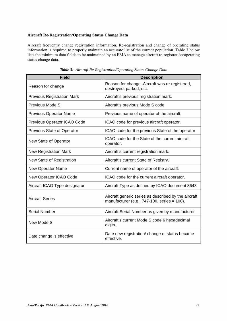
Aircraft Re-Registration/Operating Status Change Data Aircraft frequently change registration information. Re-registration and change of operating status information is required to properly maintain an accurate list of the current population. Table 3 below lists the minimum data fields to be maintained by an EMA to manage aircraft re-registration/operating status change data.
Table 3: Aircraft Re-Registration/Operating Status Change Data
Field Description
Reason for change Reason for change. Aircraft was re-registered, destroyed, parked, etc.
Previous Registration Mark Aircraft’s previous registration mark.
Previous Mode S Aircraft’s previous Mode S code.
Previous Operator Name Previous name of operator of the aircraft.
Previous Operator ICAO Code ICAO code for previous aircraft operator.
Previous State of Operator ICAO code for the previous State of the operator
New State of Operator ICAO code for the State of the current aircraft operator.
New Registration Mark Aircraft’s current registration mark.
New State of Registration Aircraft’s current State of Registry.
New Operator Name Current name of operator of the aircraft.
New Operator ICAO Code ICAO code for the current aircraft operator.
Aircraft ICAO Type designator Aircraft Type as defined by ICAO document 8643
Aircraft Series Aircraft generic series as described by the aircraft manufacturer (e.g., 747-100, series = 100).
Serial Number Aircraft Serial Number as given by manufacturer
New Mode S Aircraft’s current Mode S code 6 hexadecimal digits.
Date change is effective Date new registration/ change of status became effective.
Asia/Pacific EMA Handbook – Version 2.0, August 2010 23
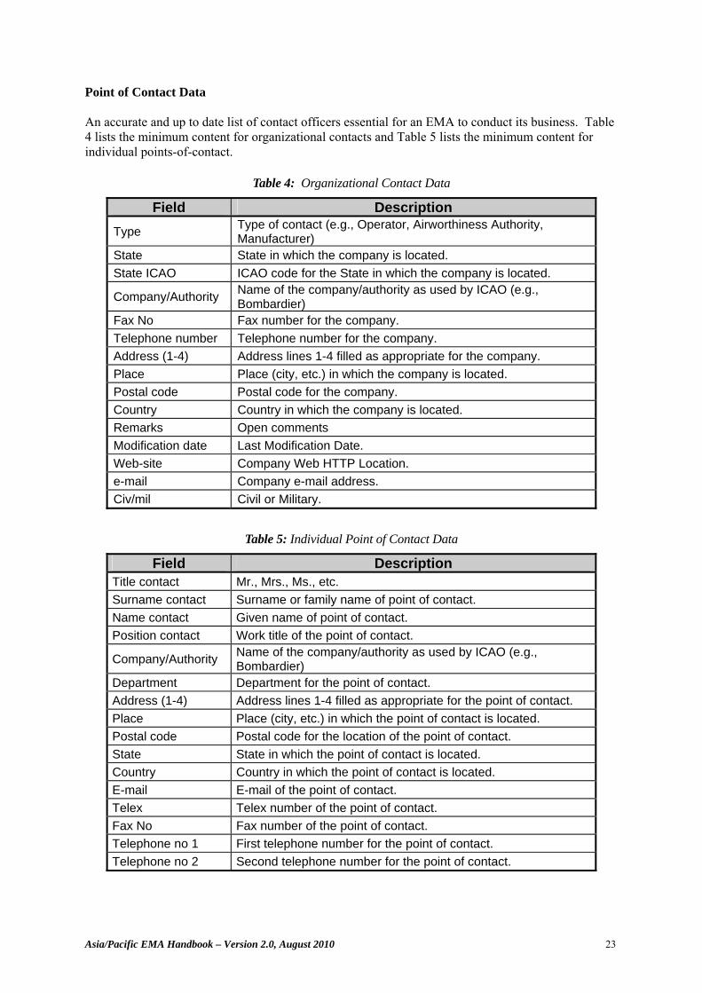
Point of Contact Data An accurate and up to date list of contact officers essential for an EMA to conduct its business. Table 4 lists the minimum content for organizational contacts and Table 5 lists the minimum content for individual points-of-contact.
Table 4: Organizational Contact Data
Field Description Type Type of contact (e.g., Operator, Airworthiness Authority,
Manufacturer) State State in which the company is located. State ICAO ICAO code for the State in which the company is located.
Company/Authority Name of the company/authority as used by ICAO (e.g., Bombardier)
Fax No Fax number for the company. Telephone number Telephone number for the company. Address (1-4) Address lines 1-4 filled as appropriate for the company. Place Place (city, etc.) in which the company is located. Postal code Postal code for the company. Country Country in which the company is located. Remarks Open comments Modification date Last Modification Date. Web-site Company Web HTTP Location. e-mail Company e-mail address. Civ/mil Civil or Military.
Table 5: Individual Point of Contact Data
Field Description Title contact Mr., Mrs., Ms., etc. Surname contact Surname or family name of point of contact. Name contact Given name of point of contact. Position contact Work title of the point of contact.
Company/Authority Name of the company/authority as used by ICAO (e.g., Bombardier)
Department Department for the point of contact. Address (1-4) Address lines 1-4 filled as appropriate for the point of contact. Place Place (city, etc.) in which the point of contact is located. Postal code Postal code for the location of the point of contact. State State in which the point of contact is located. Country Country in which the point of contact is located. E-mail E-mail of the point of contact. Telex Telex number of the point of contact. Fax No Fax number of the point of contact. Telephone no 1 First telephone number for the point of contact. Telephone no 2 Second telephone number for the point of contact.
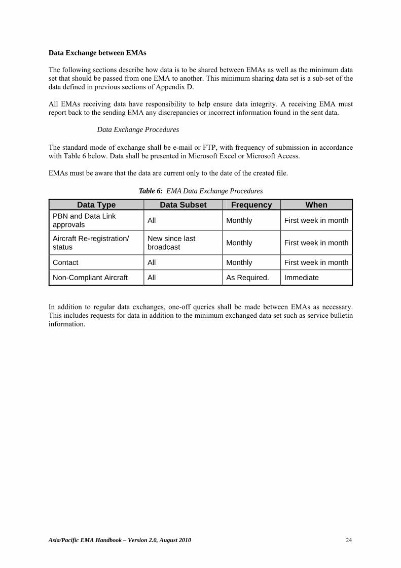
Asia/Pacific EMA Handbook – Version 2.0, August 2010 24
Data Exchange between EMAs The following sections describe how data is to be shared between EMAs as well as the minimum data set that should be passed from one EMA to another. This minimum sharing data set is a sub-set of the data defined in previous sections of Appendix D. All EMAs receiving data have responsibility to help ensure data integrity. A receiving EMA must report back to the sending EMA any discrepancies or incorrect information found in the sent data.
Data Exchange Procedures The standard mode of exchange shall be e-mail or FTP, with frequency of submission in accordance with Table 6 below. Data shall be presented in Microsoft Excel or Microsoft Access. EMAs must be aware that the data are current only to the date of the created file.
Table 6: EMA Data Exchange Procedures
Data Type Data Subset Frequency When PBN and Data Link approvals All Monthly First week in month
Aircraft Re-registration/ status
New since last broadcast Monthly First week in month
Contact All Monthly First week in month
Non-Compliant Aircraft All As Required. Immediate
In addition to regular data exchanges, one-off queries shall be made between EMAs as necessary. This includes requests for data in addition to the minimum exchanged data set such as service bulletin information.
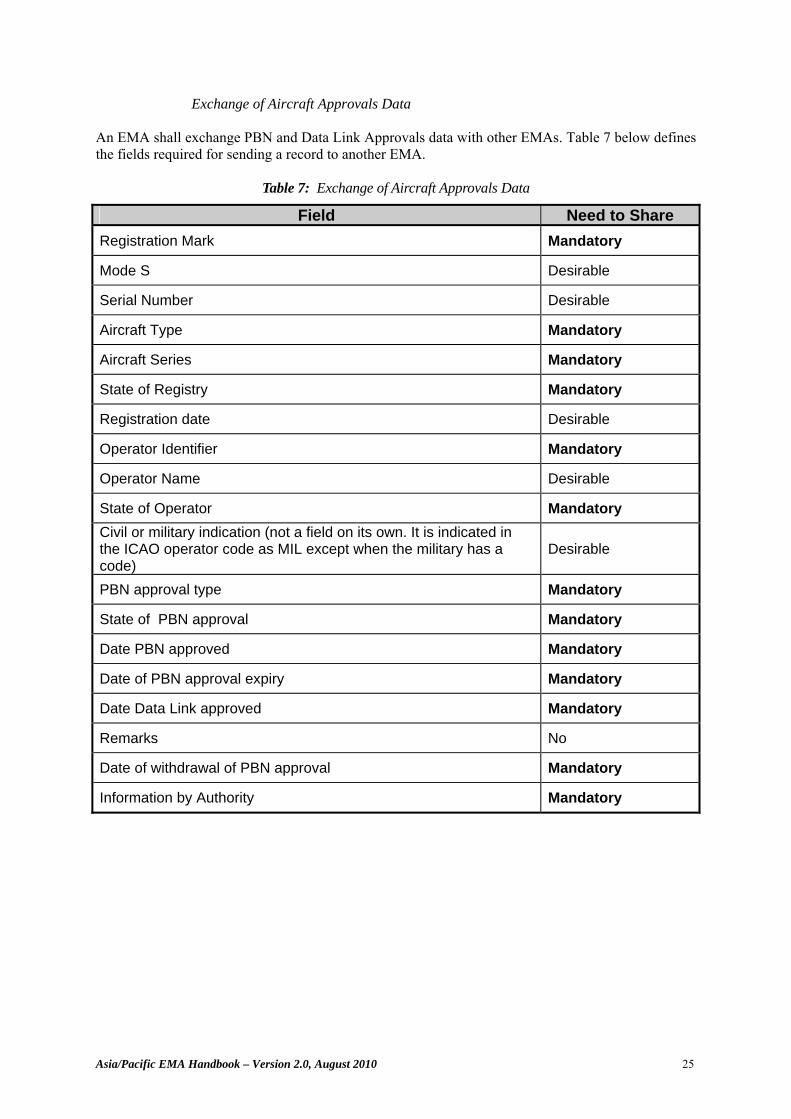
Asia/Pacific EMA Handbook – Version 2.0, August 2010 25
Exchange of Aircraft Approvals Data An EMA shall exchange PBN and Data Link Approvals data with other EMAs. Table 7 below defines the fields required for sending a record to another EMA.
Table 7: Exchange of Aircraft Approvals Data
Field Need to Share Registration Mark Mandatory
Mode S Desirable
Serial Number Desirable
Aircraft Type Mandatory
Aircraft Series Mandatory
State of Registry Mandatory
Registration date Desirable
Operator Identifier Mandatory
Operator Name Desirable
State of Operator Mandatory Civil or military indication (not a field on its own. It is indicated in the ICAO operator code as MIL except when the military has a code)
Desirable
PBN approval type Mandatory
State of PBN approval Mandatory
Date PBN approved Mandatory
Date of PBN approval expiry Mandatory
Date Data Link approved Mandatory
Remarks No
Date of withdrawal of PBN approval Mandatory
Information by Authority Mandatory
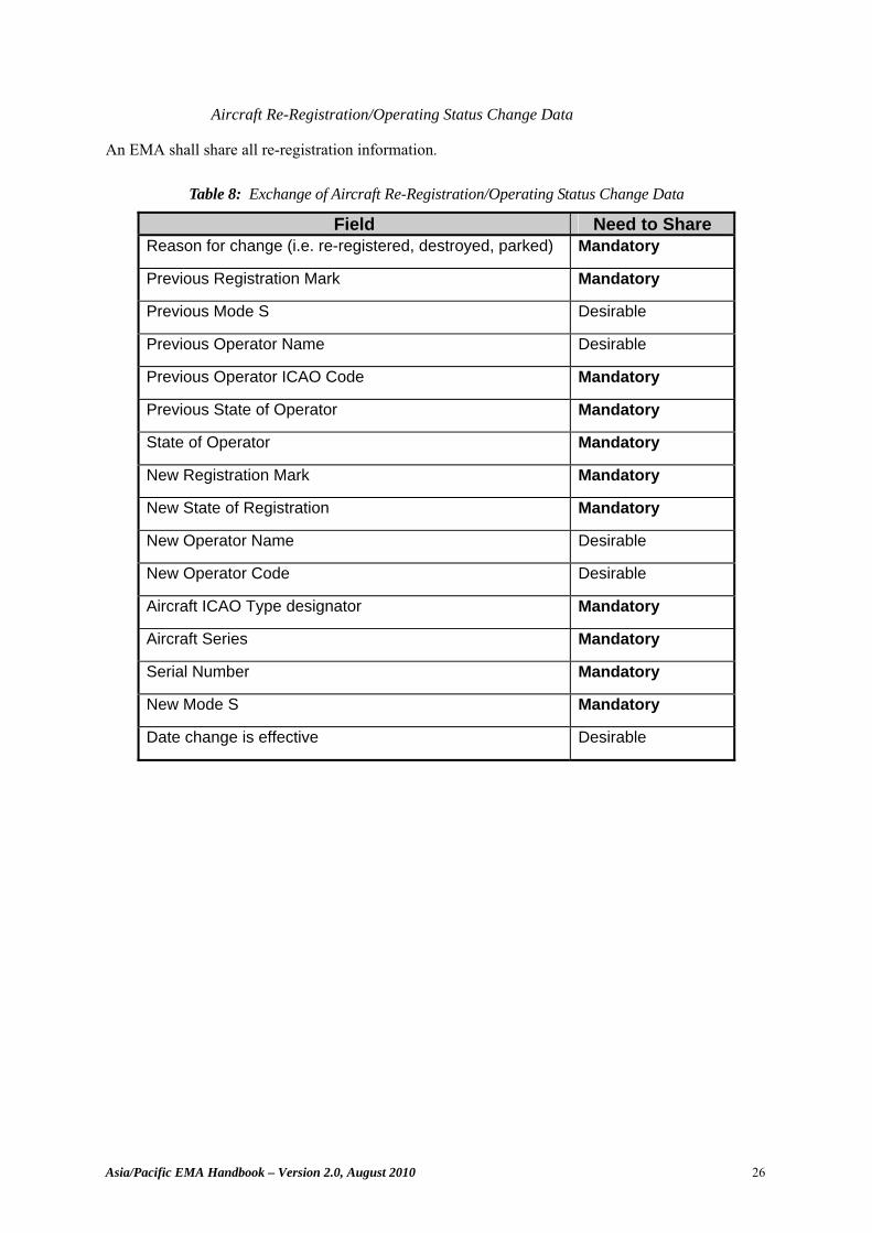
Asia/Pacific EMA Handbook – Version 2.0, August 2010 26
Aircraft Re-Registration/Operating Status Change Data An EMA shall share all re-registration information.
Table 8: Exchange of Aircraft Re-Registration/Operating Status Change Data
Field Need to Share Reason for change (i.e. re-registered, destroyed, parked) Mandatory
Previous Registration Mark Mandatory
Previous Mode S Desirable
Previous Operator Name Desirable
Previous Operator ICAO Code Mandatory
Previous State of Operator Mandatory
State of Operator Mandatory
New Registration Mark Mandatory
New State of Registration Mandatory
New Operator Name Desirable
New Operator Code Desirable
Aircraft ICAO Type designator Mandatory
Aircraft Series Mandatory
Serial Number Mandatory
New Mode S Mandatory
Date change is effective Desirable
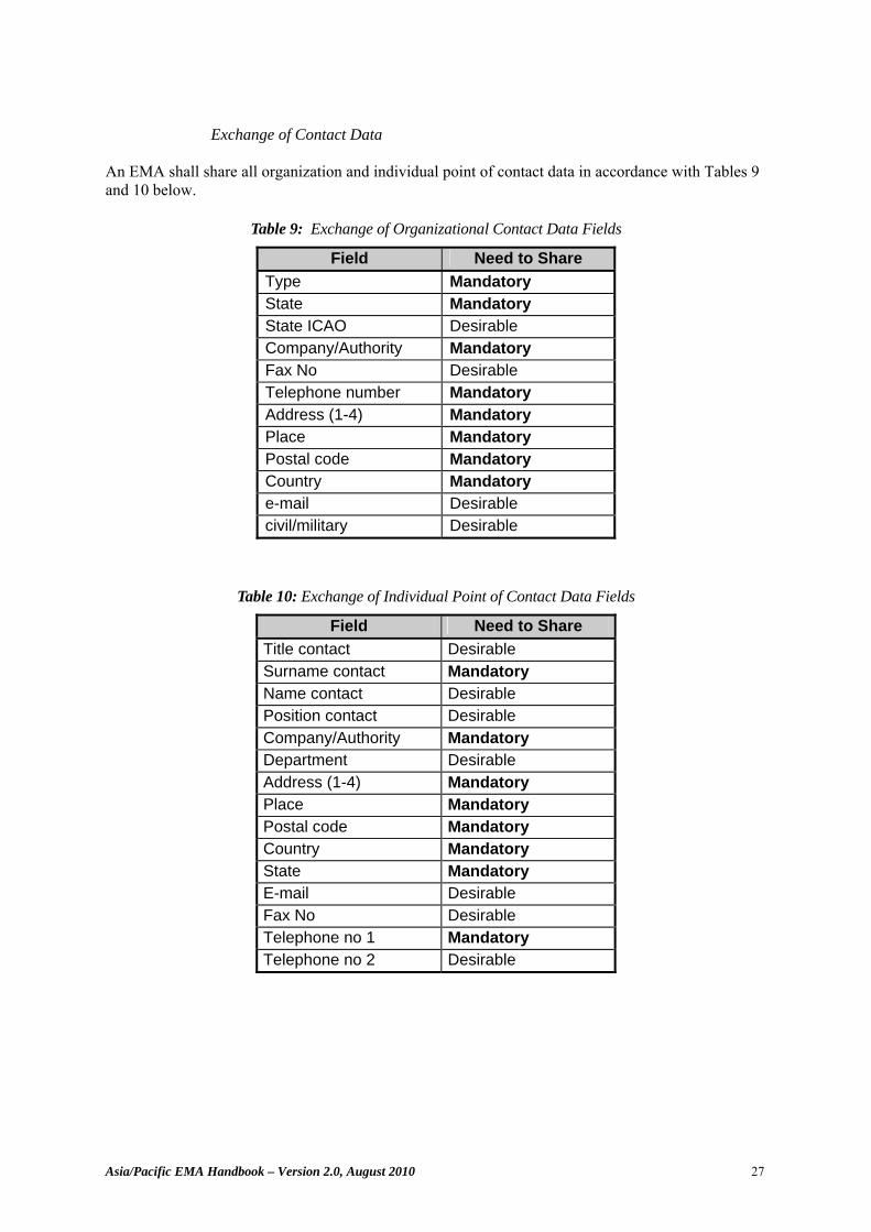
Asia/Pacific EMA Handbook – Version 2.0, August 2010 27
Exchange of Contact Data
An EMA shall share all organization and individual point of contact data in accordance with Tables 9 and 10 below.
Table 9: Exchange of Organizational Contact Data Fields
Field Need to Share Type Mandatory State Mandatory State ICAO Desirable Company/Authority Mandatory Fax No Desirable Telephone number Mandatory Address (1-4) Mandatory Place Mandatory Postal code Mandatory Country Mandatory e-mail Desirable civil/military Desirable
Table 10: Exchange of Individual Point of Contact Data Fields
Field Need to Share Title contact Desirable Surname contact Mandatory Name contact Desirable Position contact Desirable Company/Authority Mandatory Department Desirable Address (1-4) Mandatory Place Mandatory Postal code Mandatory Country Mandatory State Mandatory E-mail Desirable Fax No Desirable Telephone no 1 Mandatory Telephone no 2 Desirable
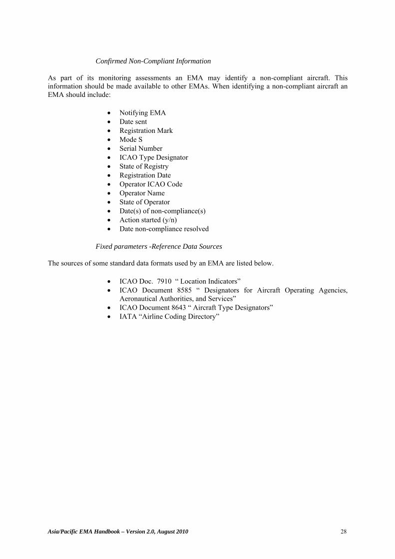
Asia/Pacific EMA Handbook – Version 2.0, August 2010 28
Confirmed Non-Compliant Information
As part of its monitoring assessments an EMA may identify a non-compliant aircraft. This information should be made available to other EMAs. When identifying a non-compliant aircraft an EMA should include:
• Notifying EMA • Date sent • Registration Mark • Mode S • Serial Number • ICAO Type Designator • State of Registry • Registration Date • Operator ICAO Code • Operator Name • State of Operator • Date(s) of non-compliance(s) • Action started (y/n) • Date non-compliance resolved
Fixed parameters -Reference Data Sources
The sources of some standard data formats used by an EMA are listed below.
• ICAO Doc. 7910 “ Location Indicators” • ICAO Document 8585 “ Designators for Aircraft Operating Agencies,
Aeronautical Authorities, and Services” • ICAO Document 8643 “ Aircraft Type Designators” • IATA “Airline Coding Directory”
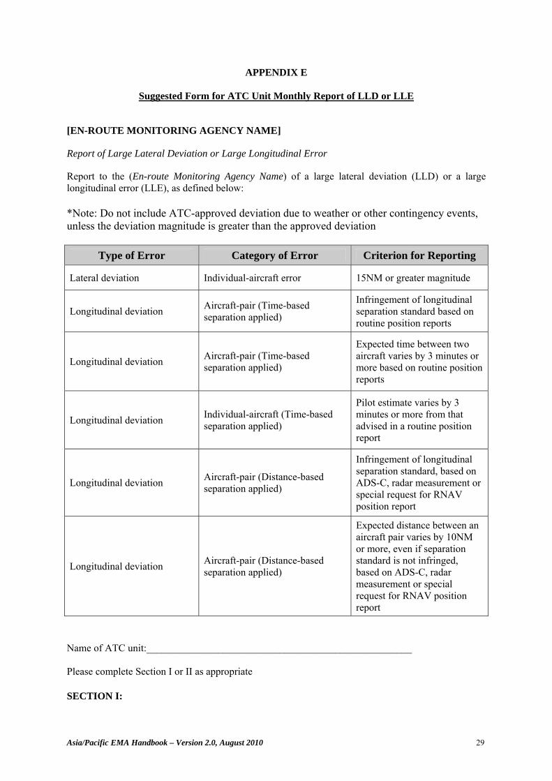
Asia/Pacific EMA Handbook – Version 2.0, August 2010 29
APPENDIX E
Suggested Form for ATC Unit Monthly Report of LLD or LLE
[EN-ROUTE MONITORING AGENCY NAME]
Report of Large Lateral Deviation or Large Longitudinal Error
Report to the (En-route Monitoring Agency Name) of a large lateral deviation (LLD) or a large longitudinal error (LLE), as defined below: *Note: Do not include ATC-approved deviation due to weather or other contingency events, unless the deviation magnitude is greater than the approved deviation
Type of Error Category of Error Criterion for Reporting
Lateral deviation Individual-aircraft error 15NM or greater magnitude
Longitudinal deviation Aircraft-pair (Time-based separation applied)
Infringement of longitudinal separation standard based on routine position reports
Longitudinal deviation Aircraft-pair (Time-based separation applied)
Expected time between two aircraft varies by 3 minutes or more based on routine position reports
Longitudinal deviation Individual-aircraft (Time-based separation applied)
Pilot estimate varies by 3 minutes or more from that advised in a routine position report
Longitudinal deviation Aircraft-pair (Distance-based separation applied)
Infringement of longitudinal separation standard, based on ADS-C, radar measurement or special request for RNAV position report
Longitudinal deviation Aircraft-pair (Distance-based separation applied)
Expected distance between an aircraft pair varies by 10NM or more, even if separation standard is not infringed, based on ADS-C, radar measurement or special request for RNAV position report
Name of ATC unit:____________________________________________________ Please complete Section I or II as appropriate SECTION I:
Asia/Pacific EMA Handbook – Version 2.0, August 2010 30
There were no reports of LLDs or LLEs for the month of __________ SECTION II: There was/were _____ report(s) of LLD There was/were _____ report(s) of LLE Details of the LLDs and LLEs are attached. (Please use a separate form for each report of lateral deviation or longitudinal error). When complete please forward the report(s) to: En-route Monitoring Agency Name Postal address Telephone: Fax: E-Mail:
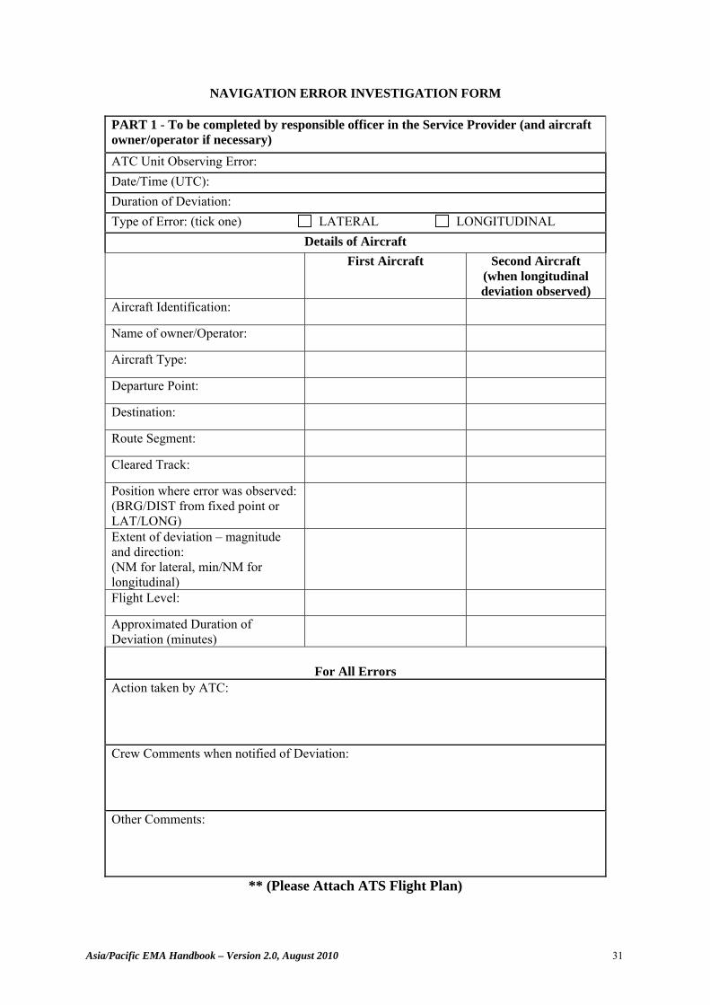
Asia/Pacific EMA Handbook – Version 2.0, August 2010 31
NAVIGATION ERROR INVESTIGATION FORM
PART 1 - To be completed by responsible officer in the Service Provider (and aircraft owner/operator if necessary) ATC Unit Observing Error: Date/Time (UTC): Duration of Deviation: Type of Error: (tick one) LATERAL LONGITUDINAL
Details of Aircraft First Aircraft
Second Aircraft
(when longitudinal deviation observed)
Aircraft Identification:
Name of owner/Operator:
Aircraft Type:
Departure Point:
Destination:
Route Segment:
Cleared Track:
Position where error was observed: (BRG/DIST from fixed point or LAT/LONG)
Extent of deviation – magnitude and direction: (NM for lateral, min/NM for longitudinal)
Flight Level:
Approximated Duration of Deviation (minutes)
For All Errors
Action taken by ATC: Crew Comments when notified of Deviation: Other Comments:
** (Please Attach ATS Flight Plan)
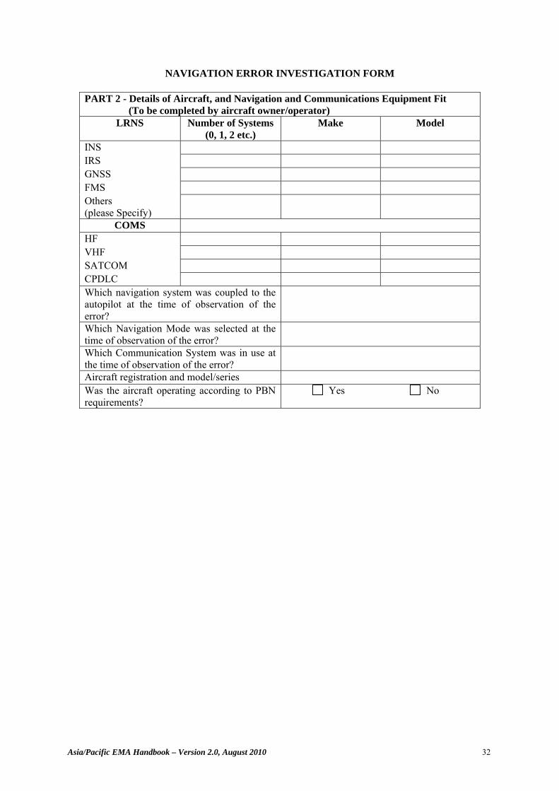
Asia/Pacific EMA Handbook – Version 2.0, August 2010 32
NAVIGATION ERROR INVESTIGATION FORM
PART 2 - Details of Aircraft, and Navigation and Communications Equipment Fit (To be completed by aircraft owner/operator)
LRNS Number of Systems (0, 1, 2 etc.)
Make Model
INS IRS GNSS FMS Others (please Specify)
COMS HF VHF SATCOM CPDLC Which navigation system was coupled to the autopilot at the time of observation of the error?
Which Navigation Mode was selected at the time of observation of the error?
Which Communication System was in use at the time of observation of the error?
Aircraft registration and model/series Was the aircraft operating according to PBN requirements?
Yes No
Asia/Pacific EMA Handbook – Version 2.0, August 2010 33
NAVIGATION ERROR INVESTIGATION FORM
PART 3 – Detailed description of incident (To be completed by owner/operator – use separate sheet if required) Please give your assessment of the actual track flown by the aircraft, and the cause of the deviation: Corrective action proposed:
PART 4 – To be completed by owner/operator, only in the event of partial or total navigation equipment failure. Navigation System Type
INS IRS/FMS Others (Please specify)
Indicate the number of units of each type which failed
Indicate position at which failure(s) occurred
Give an estimate of the duration of the equipment failure(s)
At what time were ATC advised of the failure(s)?
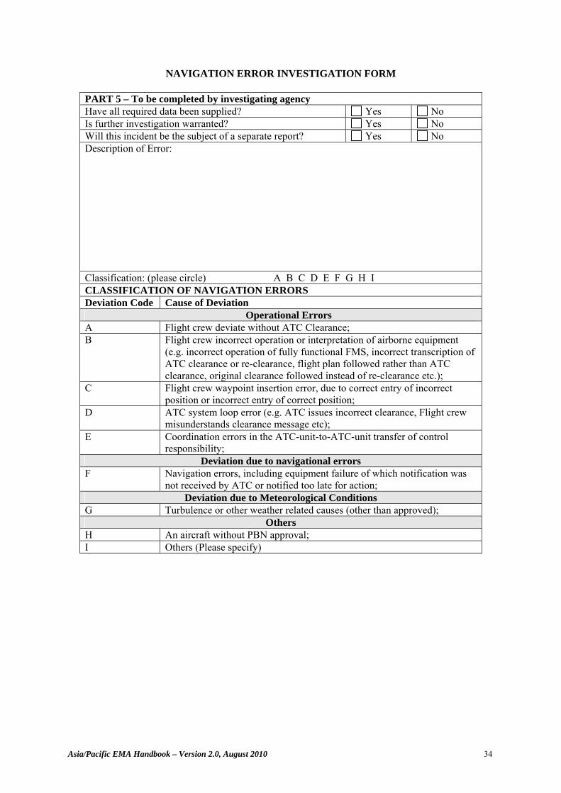
Asia/Pacific EMA Handbook – Version 2.0, August 2010 34
NAVIGATION ERROR INVESTIGATION FORM
PART 5 – To be completed by investigating agency Have all required data been supplied? Yes No Is further investigation warranted? Yes No Will this incident be the subject of a separate report? Yes No Description of Error: Classification: (please circle) A B C D E F G H I CLASSIFICATION OF NAVIGATION ERRORS Deviation Code Cause of Deviation Operational Errors A Flight crew deviate without ATC Clearance; B Flight crew incorrect operation or interpretation of airborne equipment
(e.g. incorrect operation of fully functional FMS, incorrect transcription of ATC clearance or re-clearance, flight plan followed rather than ATC clearance, original clearance followed instead of re-clearance etc.);
C Flight crew waypoint insertion error, due to correct entry of incorrect position or incorrect entry of correct position;
D ATC system loop error (e.g. ATC issues incorrect clearance, Flight crew misunderstands clearance message etc);
E Coordination errors in the ATC-unit-to-ATC-unit transfer of control responsibility;
Deviation due to navigational errors F Navigation errors, including equipment failure of which notification was
not received by ATC or notified too late for action; Deviation due to Meteorological Conditions
G Turbulence or other weather related causes (other than approved); Others
H An aircraft without PBN approval; I Others (Please specify)
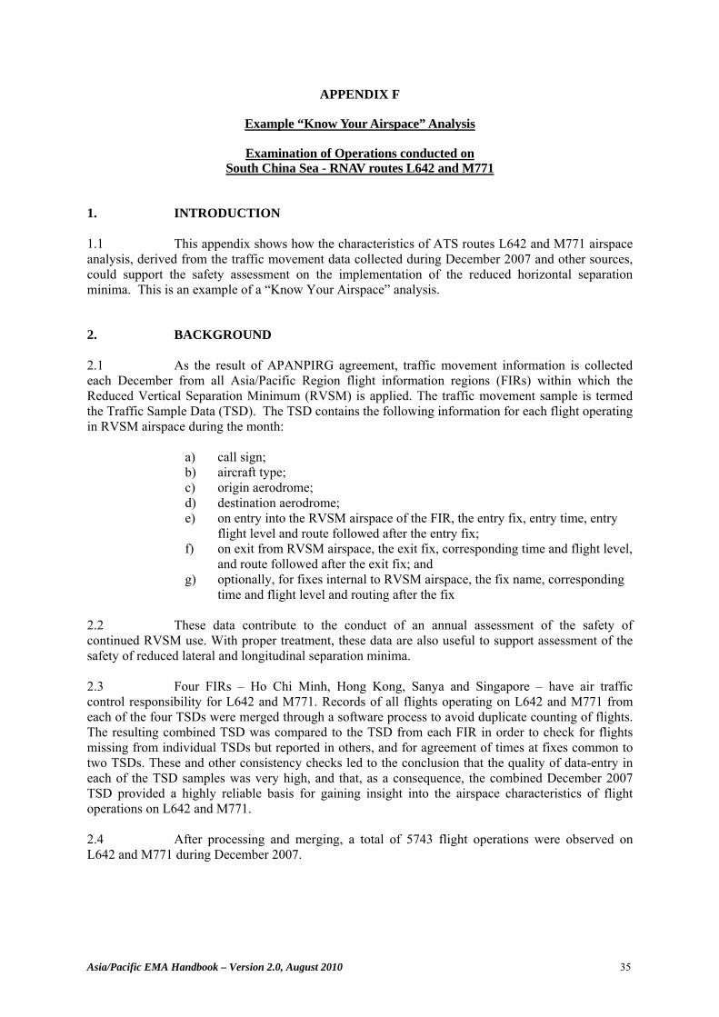
Asia/Pacific EMA Handbook – Version 2.0, August 2010 35
APPENDIX F
Example “Know Your Airspace” Analysis
Examination of Operations conducted on South China Sea - RNAV routes L642 and M771
1. INTRODUCTION 1.1 This appendix shows how the characteristics of ATS routes L642 and M771 airspace analysis, derived from the traffic movement data collected during December 2007 and other sources, could support the safety assessment on the implementation of the reduced horizontal separation minima. This is an example of a “Know Your Airspace” analysis.
2. BACKGROUND 2.1 As the result of APANPIRG agreement, traffic movement information is collected each December from all Asia/Pacific Region flight information regions (FIRs) within which the Reduced Vertical Separation Minimum (RVSM) is applied. The traffic movement sample is termed the Traffic Sample Data (TSD). The TSD contains the following information for each flight operating in RVSM airspace during the month:
a) call sign; b) aircraft type; c) origin aerodrome; d) destination aerodrome; e) on entry into the RVSM airspace of the FIR, the entry fix, entry time, entry
flight level and route followed after the entry fix; f) on exit from RVSM airspace, the exit fix, corresponding time and flight level,
and route followed after the exit fix; and g) optionally, for fixes internal to RVSM airspace, the fix name, corresponding
time and flight level and routing after the fix 2.2 These data contribute to the conduct of an annual assessment of the safety of continued RVSM use. With proper treatment, these data are also useful to support assessment of the safety of reduced lateral and longitudinal separation minima. 2.3 Four FIRs – Ho Chi Minh, Hong Kong, Sanya and Singapore – have air traffic control responsibility for L642 and M771. Records of all flights operating on L642 and M771 from each of the four TSDs were merged through a software process to avoid duplicate counting of flights. The resulting combined TSD was compared to the TSD from each FIR in order to check for flights missing from individual TSDs but reported in others, and for agreement of times at fixes common to two TSDs. These and other consistency checks led to the conclusion that the quality of data-entry in each of the TSD samples was very high, and that, as a consequence, the combined December 2007 TSD provided a highly reliable basis for gaining insight into the airspace characteristics of flight operations on L642 and M771. 2.4 After processing and merging, a total of 5743 flight operations were observed on L642 and M771 during December 2007.
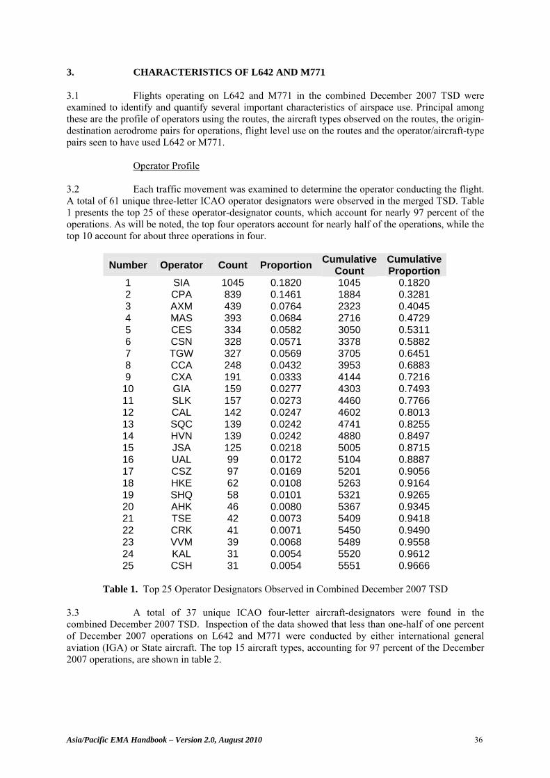
Asia/Pacific EMA Handbook – Version 2.0, August 2010 36
3. CHARACTERISTICS OF L642 AND M771 3.1 Flights operating on L642 and M771 in the combined December 2007 TSD were examined to identify and quantify several important characteristics of airspace use. Principal among these are the profile of operators using the routes, the aircraft types observed on the routes, the origin-destination aerodrome pairs for operations, flight level use on the routes and the operator/aircraft-type pairs seen to have used L642 or M771.
Operator Profile
3.2 Each traffic movement was examined to determine the operator conducting the flight. A total of 61 unique three-letter ICAO operator designators were observed in the merged TSD. Table 1 presents the top 25 of these operator-designator counts, which account for nearly 97 percent of the operations. As will be noted, the top four operators account for nearly half of the operations, while the top 10 account for about three operations in four.
Number Operator Count Proportion Cumulative Count
Cumulative Proportion
1 SIA 1045 0.1820 1045 0.1820 2 CPA 839 0.1461 1884 0.3281 3 AXM 439 0.0764 2323 0.4045 4 MAS 393 0.0684 2716 0.4729 5 CES 334 0.0582 3050 0.5311 6 CSN 328 0.0571 3378 0.5882 7 TGW 327 0.0569 3705 0.6451 8 CCA 248 0.0432 3953 0.6883 9 CXA 191 0.0333 4144 0.7216
10 GIA 159 0.0277 4303 0.7493 11 SLK 157 0.0273 4460 0.7766 12 CAL 142 0.0247 4602 0.8013 13 SQC 139 0.0242 4741 0.8255 14 HVN 139 0.0242 4880 0.8497 15 JSA 125 0.0218 5005 0.8715 16 UAL 99 0.0172 5104 0.8887 17 CSZ 97 0.0169 5201 0.9056 18 HKE 62 0.0108 5263 0.9164 19 SHQ 58 0.0101 5321 0.9265 20 AHK 46 0.0080 5367 0.9345 21 TSE 42 0.0073 5409 0.9418 22 CRK 41 0.0071 5450 0.9490 23 VVM 39 0.0068 5489 0.9558 24 KAL 31 0.0054 5520 0.9612 25 CSH 31 0.0054 5551 0.9666
Table 1. Top 25 Operator Designators Observed in Combined December 2007 TSD
3.3 A total of 37 unique ICAO four-letter aircraft-designators were found in the combined December 2007 TSD. Inspection of the data showed that less than one-half of one percent of December 2007 operations on L642 and M771 were conducted by either international general aviation (IGA) or State aircraft. The top 15 aircraft types, accounting for 97 percent of the December 2007 operations, are shown in table 2.
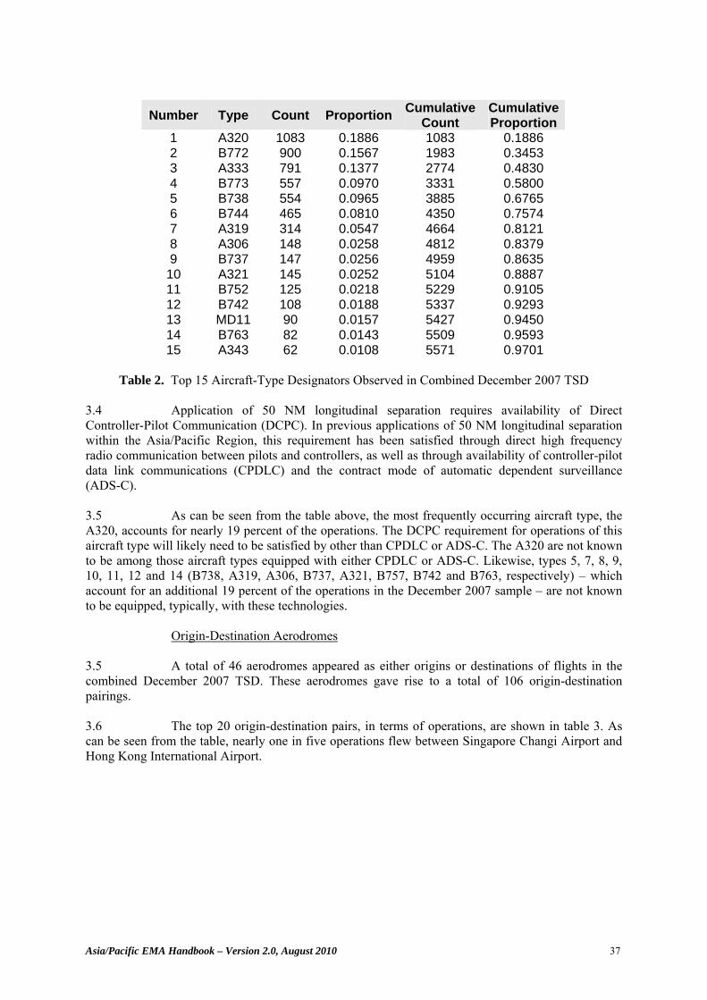
Asia/Pacific EMA Handbook – Version 2.0, August 2010 37
Number Type Count Proportion Cumulative Count
Cumulative Proportion
1 A320 1083 0.1886 1083 0.1886 2 B772 900 0.1567 1983 0.3453 3 A333 791 0.1377 2774 0.4830 4 B773 557 0.0970 3331 0.5800 5 B738 554 0.0965 3885 0.6765 6 B744 465 0.0810 4350 0.7574 7 A319 314 0.0547 4664 0.8121 8 A306 148 0.0258 4812 0.8379 9 B737 147 0.0256 4959 0.8635
10 A321 145 0.0252 5104 0.8887 11 B752 125 0.0218 5229 0.9105 12 B742 108 0.0188 5337 0.9293 13 MD11 90 0.0157 5427 0.9450 14 B763 82 0.0143 5509 0.9593 15 A343 62 0.0108 5571 0.9701
Table 2. Top 15 Aircraft-Type Designators Observed in Combined December 2007 TSD
3.4 Application of 50 NM longitudinal separation requires availability of Direct Controller-Pilot Communication (DCPC). In previous applications of 50 NM longitudinal separation within the Asia/Pacific Region, this requirement has been satisfied through direct high frequency radio communication between pilots and controllers, as well as through availability of controller-pilot data link communications (CPDLC) and the contract mode of automatic dependent surveillance (ADS-C). 3.5 As can be seen from the table above, the most frequently occurring aircraft type, the A320, accounts for nearly 19 percent of the operations. The DCPC requirement for operations of this aircraft type will likely need to be satisfied by other than CPDLC or ADS-C. The A320 are not known to be among those aircraft types equipped with either CPDLC or ADS-C. Likewise, types 5, 7, 8, 9, 10, 11, 12 and 14 (B738, A319, A306, B737, A321, B757, B742 and B763, respectively) – which account for an additional 19 percent of the operations in the December 2007 sample – are not known to be equipped, typically, with these technologies.
Origin-Destination Aerodromes 3.5 A total of 46 aerodromes appeared as either origins or destinations of flights in the combined December 2007 TSD. These aerodromes gave rise to a total of 106 origin-destination pairings. 3.6 The top 20 origin-destination pairs, in terms of operations, are shown in table 3. As can be seen from the table, nearly one in five operations flew between Singapore Changi Airport and Hong Kong International Airport.
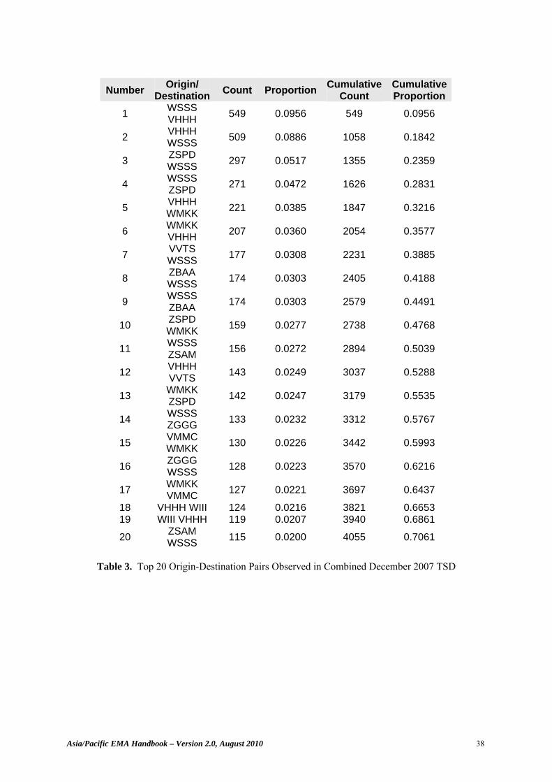
Asia/Pacific EMA Handbook – Version 2.0, August 2010 38
Number Origin/ Destination Count Proportion Cumulative
Count Cumulative Proportion
1 WSSS VHHH 549 0.0956 549 0.0956
2 VHHH WSSS 509 0.0886 1058 0.1842
3 ZSPD WSSS 297 0.0517 1355 0.2359
4 WSSS ZSPD 271 0.0472 1626 0.2831
5 VHHH WMKK 221 0.0385 1847 0.3216
6 WMKK VHHH 207 0.0360 2054 0.3577
7 VVTS WSSS 177 0.0308 2231 0.3885
8 ZBAA WSSS 174 0.0303 2405 0.4188
9 WSSS ZBAA 174 0.0303 2579 0.4491
10 ZSPD WMKK 159 0.0277 2738 0.4768
11 WSSS ZSAM 156 0.0272 2894 0.5039
12 VHHH VVTS 143 0.0249 3037 0.5288
13 WMKK ZSPD 142 0.0247 3179 0.5535
14 WSSS ZGGG 133 0.0232 3312 0.5767
15 VMMC WMKK 130 0.0226 3442 0.5993
16 ZGGG WSSS 128 0.0223 3570 0.6216
17 WMKK VMMC 127 0.0221 3697 0.6437
18 VHHH WIII 124 0.0216 3821 0.6653 19 WIII VHHH 119 0.0207 3940 0.6861 20 ZSAM
WSSS 115 0.0200 4055 0.7061
Table 3. Top 20 Origin-Destination Pairs Observed in Combined December 2007 TSD
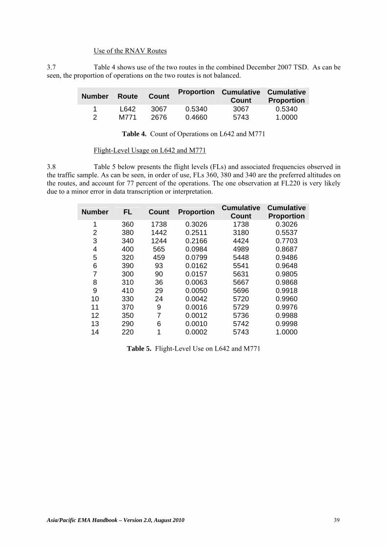
Asia/Pacific EMA Handbook – Version 2.0, August 2010 39
Use of the RNAV Routes 3.7 Table 4 shows use of the two routes in the combined December 2007 TSD. As can be seen, the proportion of operations on the two routes is not balanced.
Number Route Count Proportion
Cumulative Count
Cumulative Proportion
1 L642 3067 0.5340 3067 0.5340 2 M771 2676 0.4660 5743 1.0000
Table 4. Count of Operations on L642 and M771
Flight-Level Usage on L642 and M771
3.8 Table 5 below presents the flight levels (FLs) and associated frequencies observed in the traffic sample. As can be seen, in order of use, FLs 360, 380 and 340 are the preferred altitudes on the routes, and account for 77 percent of the operations. The one observation at FL220 is very likely due to a minor error in data transcription or interpretation.
Number FL Count Proportion Cumulative Count
Cumulative Proportion
1 360 1738 0.3026 1738 0.3026 2 380 1442 0.2511 3180 0.5537 3 340 1244 0.2166 4424 0.7703 4 400 565 0.0984 4989 0.8687 5 320 459 0.0799 5448 0.9486 6 390 93 0.0162 5541 0.9648 7 300 90 0.0157 5631 0.9805 8 310 36 0.0063 5667 0.9868 9 410 29 0.0050 5696 0.9918
10 330 24 0.0042 5720 0.9960 11 370 9 0.0016 5729 0.9976 12 350 7 0.0012 5736 0.9988 13 290 6 0.0010 5742 0.9998 14 220 1 0.0002 5743 1.0000
Table 5. Flight-Level Use on L642 and M771
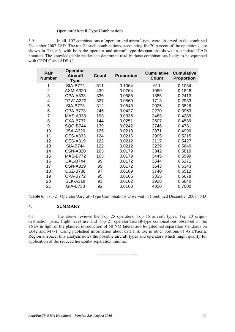
Asia/Pacific EMA Handbook – Version 2.0, August 2010 40
Operator/Aircraft-Type Combinations 3.9 In all, 107 combinations of operator and aircraft type were observed in the combined December 2007 TSD. The top 21 such combinations, accounting for 70 percent of the operations, are shown in Table 6, with both the operator and aircraft type designations shown in standard ICAO notation. The knowledgeable reader can determine readily those combinations likely to be equipped with CPDLC and ADS-C.
Pair Number
Operator-Aircraft
Type Count Proportion Cumulative
Count Cumulative Proportion
1 SIA-B772 611 0.1064 611 0.1064 2 AXM-A320 439 0.0764 1050 0.1828 3 CPA-A333 336 0.0585 1386 0.2413 4 TGW-A320 327 0.0569 1713 0.2983 5 SIA-B773 312 0.0543 2025 0.3526 6 CPA-B773 245 0.0427 2270 0.3953 7 MAS-A333 193 0.0336 2463 0.4289 8 CXA-B737 144 0.0251 2607 0.4539 9 SQC-B744 139 0.0242 2746 0.4781
10 JSA-A320 125 0.0218 2871 0.4999 11 CES-A333 124 0.0216 2995 0.5215 12 CES-A319 122 0.0212 3117 0.5427 13 SIA-B744 122 0.0212 3239 0.5640 14 CSN-A320 103 0.0179 3342 0.5819 15 MAS-B772 103 0.0179 3445 0.5999 16 UAL-B744 99 0.0172 3544 0.6171 17 CSN-A319 99 0.0172 3643 0.6343 18 CSZ-B738 97 0.0169 3740 0.6512 19 CPA-B772 95 0.0165 3835 0.6678 20 SLK-A319 93 0.0162 3928 0.6840 21 GIA-B738 92 0.0160 4020 0.7000
Table 6. Top 21 Operator/Aircraft-Type Combinations Observed in Combined December 2007 TSD 4. SUMMARY 4.1 The above reviews the Top 25 operators, Top 15 aircraft types, Top 20 origin-destination pairs, flight level use and Top 21 operator/aircraft-type combinations observed in the TSDs in light of the planned introduction of 50 NM lateral and longitudinal separation standards on L642 and M771. Using published information about data link use in other portions of Asia/Pacific Region airspace, this analysis notes the possible aircraft types and operators which might qualify for application of the reduced horizontal separation minima.
……………………….
Asia/Pacific EMA Handbook – Version 2.0, August 2010 41
APPENDIX G
Example Safety Assessment
South China Sea Collision Risk Model and Safety Assessment
1. Introduction 1.1 The South East Asia Safety Monitoring Agency (SEASMA), an En-route Monitoring Agency (EMA), is responsible for supporting continued safe use of the six major air traffic service routes in South China Sea international airspace. This support consists of discharging the EMA duties listed in the Asia/Pacific En-route Monitoring Agency Handbook. 1.2 The purpose of this appendix is to present an example of a safety assessment, as conducted by SEASMA on the six major South China Sea routes, together with the collision risk model used, to assess compliance with APANPIRG-agreed Target Level of Safety (TLS) values for the maintenance of lateral and longitudinal separation standards. The examination period covered is 1 May 2008 through 30 April 2009. 2. Background 2.1 The six South China Sea routes – L642, M771, N892, L625, N884 and M767 – were introduced in November 2001 in order to relieve congestion in the airspace. At the same time, State approval for Required Navigation Performance 10 (RNP 10) (now RNAV 10 under Performance Based Navigation (PBN) terminology) became mandatory for operation at or above flight 290 (FL 290). 2.2 This performance requirement was the basis for employing a minimum lateral separation standard of 60NM between-route centerlines. As shown in Table 1, the six routes are organized into three route-pairs to serve principal origin destination points, no pre-departure clearance (No-PDC) flight levels by route and some information about routes crossing the RNAV routes.
Asia/Pacific EMA Handbook – Version 2.0, August 2010 42
Route Principal Service Direction of Flow No-PDC Flight LevelsRNAV L642 Hong
Kong/Singapore- Kuala Lumpur
Northeast-southwest 310, 320, 350, 360, 390 and 400
RNAV M771 Singapore-Kuala
Lumpur /Hong Kong Southwest-northeast Same as L642
RNAV N892 Northeast Asia- Taiwan/Singapore
Northeast-southwest Same as L642
RNAV L625 Singapore /NortheastAsia-Taiwan
Southwest-northeast Same as L642
RNAV N884 Singapore /Manila Southwest-northeast Same as L642 RNAV M767 Manila/Singapore Northeast-southwest Same as L642
Crossing Routes Various Bidirectional Dependent upon route
Table 1: Characteristics of Air Traffic Service Routes in South China Sea
2.3 The longitudinal separation minimum published for the six routes in November 2001 was 10 minutes with Mach Number Technique (MNT), or 80NM RNAV. 2.4 Radar monitoring of horizontal plane navigational performance was initiated with introduction of the RNAV routes. The enabling Letter of Agreement (LOA) – signed by China, Hong Kong China, Indonesia, Malaysia, Singapore, Thailand, Vietnam, and Philippines – specified details concerning the categories of errors to be monitored and reported to Singapore on a monthly basis. The LOA also called for reporting associated counts of flights monitored. 2.5 In anticipation of horizontal-plane separation changes being pursued by the ICAO South-East Asia RNP Task Force (RNP-SEA/TF), the LOA was revised in 2008 to formalize certain monitoring activities which had been carried out previously on an informal basis. Table 2 indicates the fixes where monitoring is taking place under the revised LOA.
Route Fixes Monitoring Authority L642 ESPOB to ENREP Singapore M771 DULOP and DUMOL Hong Kong, China N892 MELAS and MABLI Singapore L625 AKOTA and AVMUP Philippines N884 LULBU and LEGED Philippines M767 TEGID to BOBOB Singapore
Table 2: Monitored Fixes in South China Sea Airspace
2.6 Since adoption of the original LOA, all instances of certain types of lateral and longitudinal errors have been reported to Singapore. The specifics of error-reporting are shown in Table 3. As will be noted, monitoring systems include automatic dependent surveillance – contract (ADS-C) and position reports, in addition to radar.
Asia/Pacific EMA Handbook – Version 2.0, August 2010 43
Type of Error Category of Error Criterion for Reporting
Lateral deviation Individual-aircraft error 15NM or greater magnitude
Longitudinal deviation Aircraft-pair (Time-based separation applied)
Infringement of longitudinal separation standard based on
routine position reports
Longitudinal deviation Aircraft-pair (Time-based separation applied)
Expected time between two aircraft varies by 3 minutes or
more based on routine position reports
Longitudinal deviation Aircraft-pair (Time-based separation applied)
Pilot estimate varies by 3 minutes or more from that
advised in a routine position report
Longitudinal deviation Aircraft-pair (Distance-based separation applied)
Infringement of longitudinal separation standard, based
on ADS, radar measurement or special request for RNAV
position report
Longitudinal deviation Aircraft-pair (Distance-based separation applied)
Expected distance between an aircraft pair varies by 10NM or more, even if
separation standard is not infringed, based on ADS,
radar measurement or special request for RNAV position
report
Table 3. Reporting Criteria for South China Sea Monitoring Programme 2.7 The monitoring criteria in Table 3 were chosen to support eventual work by the RNP-SEA/TF to introduce PBN separation standards, specifically RNAV 10-based 50NM lateral and longitudinal separation and RNP 4-based 30NM lateral and longitudinal separation. On 2 July 2008, the first of these separation reductions was introduced: the lateral separation standard between L642 and M771 was changed to 50NM and the preferred basis for longitudinal separation on these routes was changed to distance from time, with the minimum longitudinal separation standard between co-altitudes pairs reduced to 50NM. 3. Results of Data Collection 3.1 Table 4 shows the record of ANSP reporting of observed large errors and corresponding traffic counts covered by the South China Sea monitoring programme LOA (2008 revision) for the period May 2008 through April 2009.
Asia/Pacific EMA Handbook – Version 2.0, August 2010 44
Month Report received from:
Hong Kong, China Philippines Singapore May 2008 Yes No Yes June 2008 Yes No Yes July 2008 Yes No Yes
August 2008 Yes Yes Yes September 2008 Yes Yes Yes
October 2008 Yes Yes Yes November 2008 Yes Yes Yes December 2008 Yes Yes Yes January 2009 Yes Yes Yes February 2009 Yes Yes Yes
March 2009 Yes Yes Yes April 2009 Yes Yes Yes
Table 4. Record of ANSP Reporting by Month for Period May 2008 through April 2009
3.2 Reported Traffic Counts for May 2008 through April 2009 Monitoring Period 3.2.1 Table 5 presents the total traffic counts reported by month transiting all South China Sea monitoring fixes.
Monitoring Month Total Monthly Traffic Count Reported Over Monitored
Fixes
Cumulative 12-Month Count of Traffic Reported Over Monitored Fixes Through
Monitoring Month May 2008 8123 81591 June 2008 7743 83239 July 2008 8423 85383
August 2008 7568 86638 September 2008 7293 87800
October 2008 7673 89029 November 2008 6576 89457 December 2008 6665 89597 January 2009 7244 90880 February 2009 6380 89434
March 2009 7016 88438 April 2009 6603 87307
Table 5. Monthly Count of Monitored Flights Operating on South China Sea RNAV Routes
3.3 Reports of LLD for May 2008 to April 2009 Monitoring Period 3.3.1 There were no reported LLDs during the period May 2008 through April 2009. 3.3.2 Table 6 below presents the cumulative totals of LLDs in a manner similar to the traffic counts of table 5.
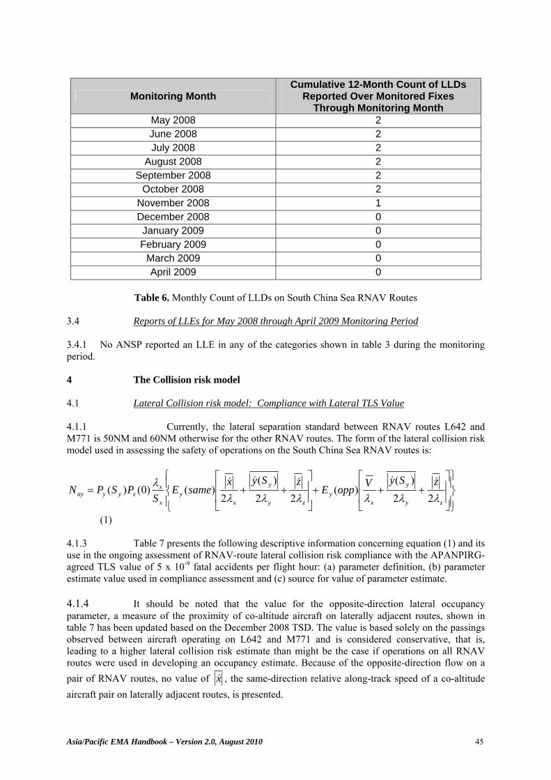
Asia/Pacific EMA Handbook – Version 2.0, August 2010 45
Monitoring Month Cumulative 12-Month Count of LLDs
Reported Over Monitored Fixes Through Monitoring Month
May 2008 2 June 2008 2 July 2008 2
August 2008 2 September 2008 2
October 2008 2 November 2008 1 December 2008 0 January 2009 0 February 2009 0
March 2009 0 April 2009 0
Table 6. Monthly Count of LLDs on South China Sea RNAV Routes
3.4 Reports of LLEs for May 2008 through April 2009 Monitoring Period 3.4.1 No ANSP reported an LLE in any of the categories shown in table 3 during the monitoring period. 4 The Collision risk model 4.1 Lateral Collision risk model: Compliance with Lateral TLS Value 4.1.1 Currently, the lateral separation standard between RNAV routes L642 and M771 is 50NM and 60NM otherwise for the other RNAV routes. The form of the lateral collision risk model used in assessing the safety of operations on the South China Sea RNAV routes is:
⎪⎭
⎪⎬⎫
⎥⎥
⎦
⎤
⎢⎢
⎣
⎡+++
⎪⎩
⎪⎨⎧
⎥⎥
⎦
⎤
⎢⎢
⎣
⎡++=
zy
y
xy
zy
y
xy
x
xzyyay
zSyVoppEzSyx
sameES
PSPNλλλλλλ
λ22
)()(
22)(
2)()0()(
&&&&&
(1) 4.1.3 Table 7 presents the following descriptive information concerning equation (1) and its use in the ongoing assessment of RNAV-route lateral collision risk compliance with the APANPIRG-agreed TLS value of 5 x 10⁻⁹ fatal accidents per flight hour: (a) parameter definition, (b) parameter estimate value used in compliance assessment and (c) source for value of parameter estimate. 4.1.4 It should be noted that the value for the opposite-direction lateral occupancy parameter, a measure of the proximity of co-altitude aircraft on laterally adjacent routes, shown in table 7 has been updated based on the December 2008 TSD. The value is based solely on the passings observed between aircraft operating on L642 and M771 and is considered conservative, that is, leading to a higher lateral collision risk estimate than might be the case if operations on all RNAV routes were used in developing an occupancy estimate. Because of the opposite-direction flow on a pair of RNAV routes, no value of x& , the same-direction relative along-track speed of a co-altitude aircraft pair on laterally adjacent routes, is presented.
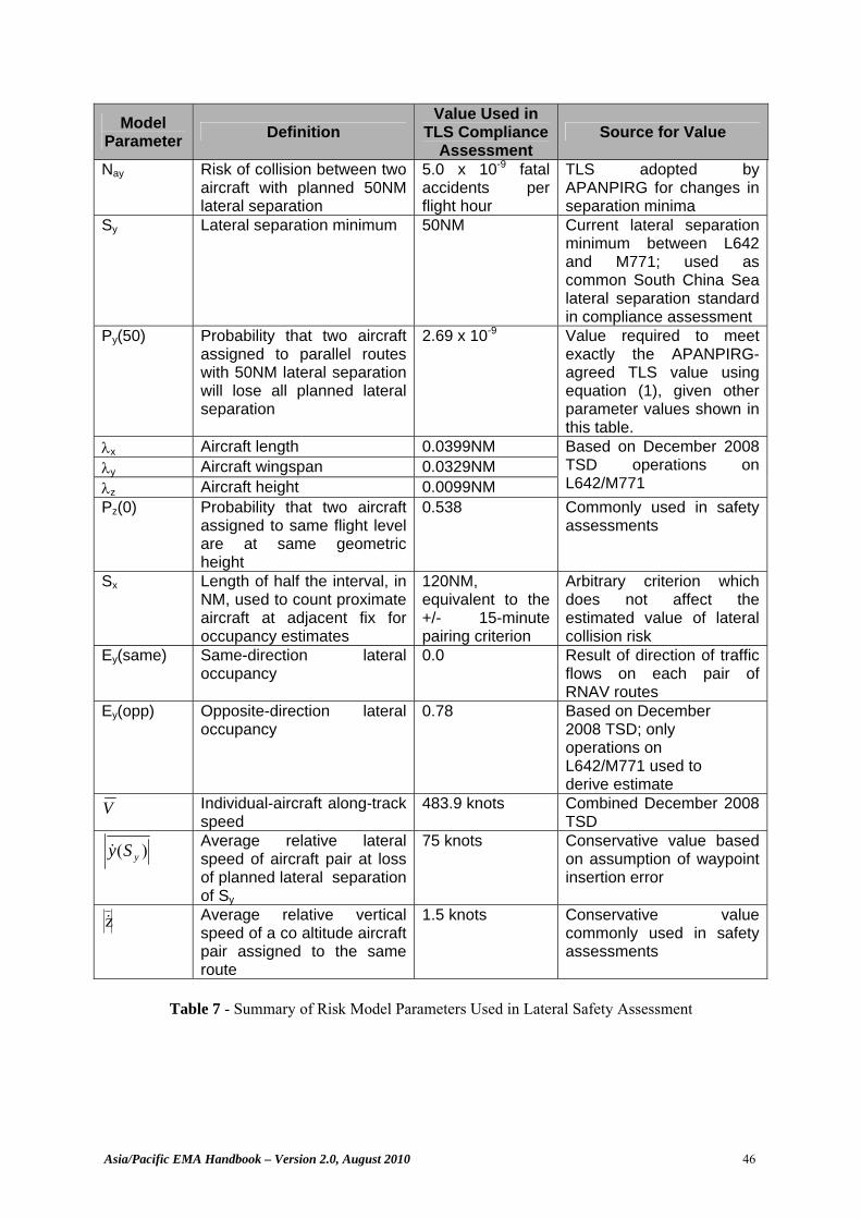
Asia/Pacific EMA Handbook – Version 2.0, August 2010 46
Model Parameter Definition
Value Used in TLS Compliance
Assessment Source for Value
Nay Risk of collision between two aircraft with planned 50NM lateral separation
5.0 x 10⁻⁹ fatal accidents per flight hour
TLS adopted by APANPIRG for changes in separation minima
Sy Lateral separation minimum 50NM Current lateral separation minimum between L642 and M771; used as common South China Sea lateral separation standard in compliance assessment
Py(50) Probability that two aircraft assigned to parallel routes with 50NM lateral separation will lose all planned lateral separation
2.69 x 10⁻⁹ Value required to meet exactly the APANPIRG-agreed TLS value using equation (1), given other parameter values shown in this table.
λx Aircraft length 0.0399NM λy Aircraft wingspan 0.0329NM λz Aircraft height 0.0099NM
Based on December 2008 TSD operations on L642/M771
Pz(0) Probability that two aircraft assigned to same flight level are at same geometric height
0.538 Commonly used in safety assessments
Sx Length of half the interval, in NM, used to count proximate aircraft at adjacent fix for occupancy estimates
120NM, equivalent to the +/- 15-minute pairing criterion
Arbitrary criterion which does not affect the estimated value of lateral collision risk
Ey(same) Same-direction lateral occupancy
0.0 Result of direction of traffic flows on each pair of RNAV routes
Ey(opp) Opposite-direction lateral occupancy
0.78 Based on December 2008 TSD; only operations on L642/M771 used to derive estimate
V Individual-aircraft along-track speed
483.9 knots Combined December 2008 TSD
)( ySy& Average relative lateral speed of aircraft pair at loss of planned lateral separation of Sy
75 knots Conservative value based on assumption of waypoint insertion error
&z Average relative vertical speed of a co altitude aircraft pair assigned to the same route
1.5 knots Conservative value commonly used in safety assessments
Table 7 - Summary of Risk Model Parameters Used in Lateral Safety Assessment
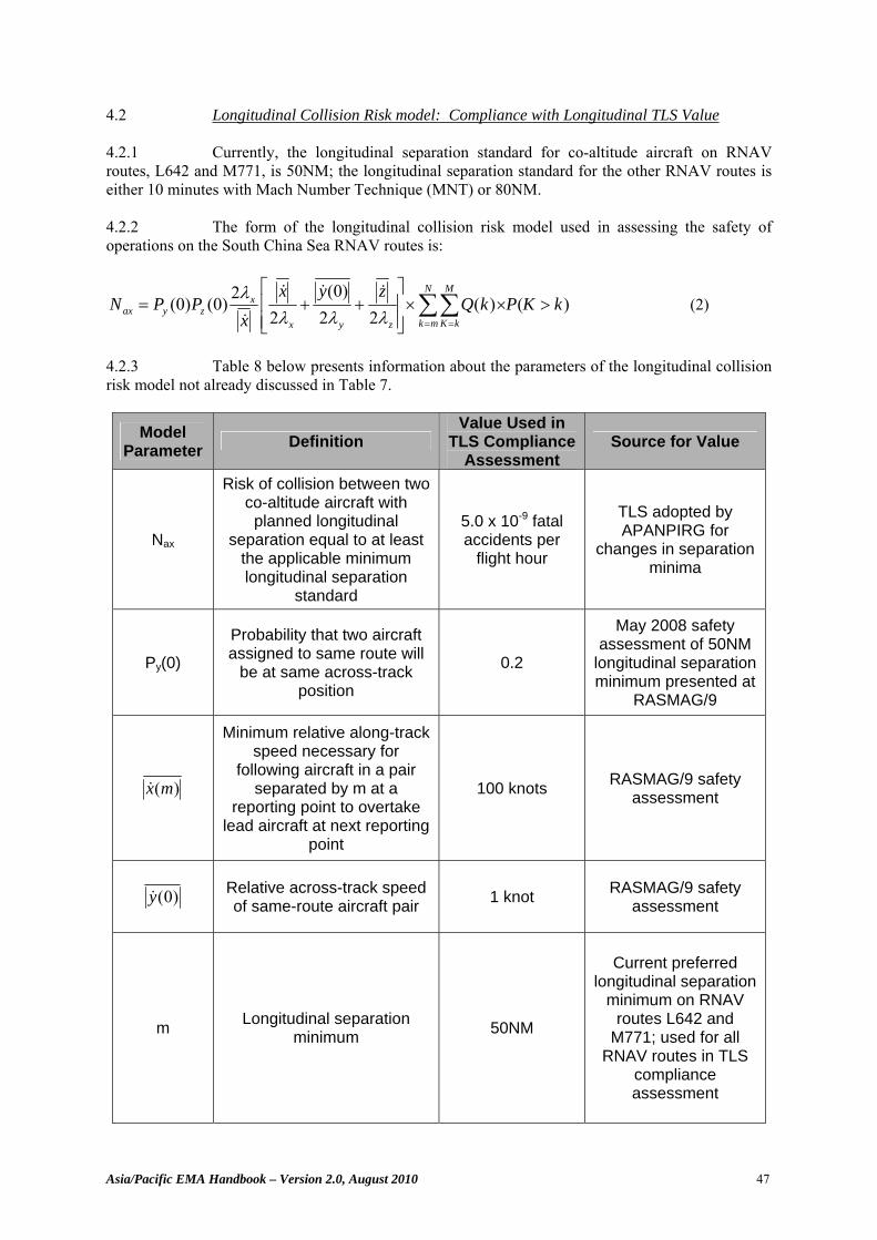
Asia/Pacific EMA Handbook – Version 2.0, August 2010 47
4.2 Longitudinal Collision Risk model: Compliance with Longitudinal TLS Value 4.2.1 Currently, the longitudinal separation standard for co-altitude aircraft on RNAV routes, L642 and M771, is 50NM; the longitudinal separation standard for the other RNAV routes is either 10 minutes with Mach Number Technique (MNT) or 80NM. 4.2.2 The form of the longitudinal collision risk model used in assessing the safety of operations on the South China Sea RNAV routes is:
)()(22
)0(2
2(0)(0) kKPkQzyx
xPPN
N
mk
M
kKzyx
xzyax >××
⎥⎥⎦
⎤
⎢⎢⎣
⎡++= ∑∑
= =λλλλ &&&
& (2)
4.2.3 Table 8 below presents information about the parameters of the longitudinal collision risk model not already discussed in Table 7.
Model Parameter Definition
Value Used in TLS Compliance
Assessment Source for Value
Nax
Risk of collision between two co-altitude aircraft with
planned longitudinal separation equal to at least
the applicable minimum longitudinal separation
standard
5.0 x 10⁻⁹ fatal accidents per
flight hour
TLS adopted by APANPIRG for
changes in separation minima
Py(0) Probability that two aircraft assigned to same route will
be at same across-track position
0.2
May 2008 safety assessment of 50NM
longitudinal separation minimum presented at
RASMAG/9
)(mx&
Minimum relative along-track speed necessary for
following aircraft in a pair separated by m at a
reporting point to overtake lead aircraft at next reporting
point
100 knots RASMAG/9 safety assessment
)0(y& Relative across-track speed of same-route aircraft pair 1 knot RASMAG/9 safety
assessment
m Longitudinal separation minimum 50NM
Current preferred
longitudinal separation minimum on RNAV
routes L642 and M771; used for all
RNAV routes in TLS compliance assessment
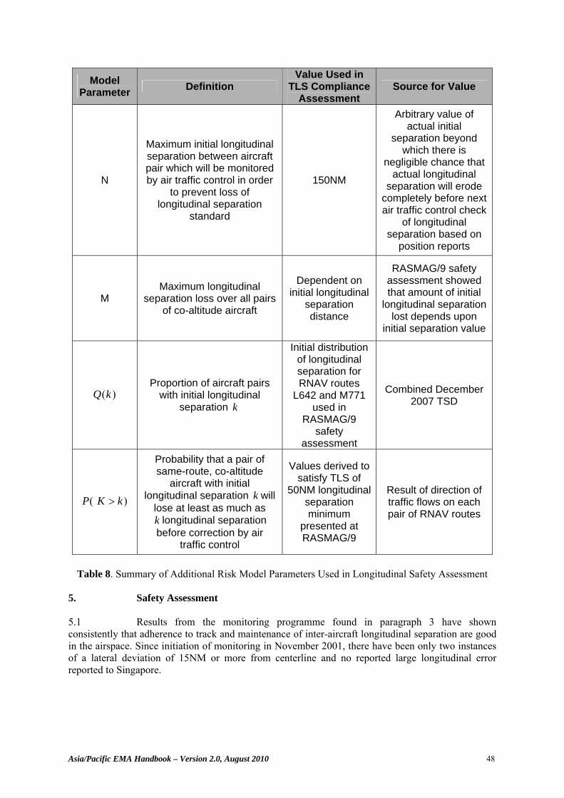
Asia/Pacific EMA Handbook – Version 2.0, August 2010 48
Model Parameter Definition
Value Used in TLS Compliance
Assessment Source for Value
N
Maximum initial longitudinal separation between aircraft pair which will be monitored by air traffic control in order
to prevent loss of longitudinal separation
standard
150NM
Arbitrary value of actual initial
separation beyond which there is
negligible chance that actual longitudinal
separation will erode completely before next air traffic control check
of longitudinal separation based on
position reports
M Maximum longitudinal
separation loss over all pairs of co-altitude aircraft
Dependent on initial longitudinal
separation distance
RASMAG/9 safety assessment showed that amount of initial
longitudinal separation lost depends upon
initial separation value
)(kQ
Proportion of aircraft pairs with initial longitudinal
separation k
Initial distribution of longitudinal separation for RNAV routes
L642 and M771 used in
RASMAG/9 safety
assessment
Combined December 2007 TSD
(P )kK >
Probability that a pair of same-route, co-altitude
aircraft with initial longitudinal separation k will
lose at least as much as k longitudinal separation before correction by air
traffic control
Values derived to satisfy TLS of
50NM longitudinal separation minimum
presented at RASMAG/9
Result of direction of traffic flows on each pair of RNAV routes
Table 8. Summary of Additional Risk Model Parameters Used in Longitudinal Safety Assessment
5. Safety Assessment 5.1 Results from the monitoring programme found in paragraph 3 have shown consistently that adherence to track and maintenance of inter-aircraft longitudinal separation are good in the airspace. Since initiation of monitoring in November 2001, there have been only two instances of a lateral deviation of 15NM or more from centerline and no reported large longitudinal error reported to Singapore.
Asia/Pacific EMA Handbook – Version 2.0, August 2010 49
5.2 Since January 2005, States have monitored roughly 300,000 flights while recording the two instances of large lateral deviations and no instances of reportable longitudinal errors. A reasonable conclusion from these results is that, whatever the values that pertain in the lateral and longitudinal dimensions, the rates of occurrence of large horizontal-plane navigational errors are so low that they do not evidence themselves frequently in the number of flights monitored. 5.3 The few instances of reported large errors are consistent with several facts about the South China Sea operational environment, as follows:
• the six RNAV routes have been fixed at the same coordinates since November 2001,
• more than 97 percent of operations are conducted by commercial operators regularly flying the routes,
• more than 98 percent of the operations are conducted using aircraft types of the most recent generations, and
• more than 60 percent of South China operations are conducted on the L642 and M771 routes where radar surveillance and very high frequency radio coverage are extant throughout almost all of the route lengths, providing the opportunity for controller intervention in the event that an aircraft or aircraft pair begins to stray.
5.4 Given the small number of reported large errors, the estimation of lateral and longitudinal collision risk is more challenging. This is because it is more difficult to estimate the two key probabilities on which the risk values depend: the probability that a pair of aircraft will lose, respectively, all planned 50 NM lateral separation and 50 NM minimum longitudinal separation – repressed symbolically as Py(50) and Px(Sx│Sx ≥50). 5.5 The approach taken to estimating the two probability values is the same. It will be described for the case of lateral separation; differences in the outcome for longitudinal separation will be discussed after the lateral-separation case is explained. 5.6 Direct estimation of Lateral Collision Risk 5.6.1 This approach considers that the process of monitoring a flight has the following properties:
• a flight’s performance observed at a monitored fix is the same as its performance during that portion of its operation where performance is not monitored formally,
• from the standpoint of the monitoring programme, there are only two possible outcomes for a flight: either observing a 15-NM or greater magnitude lateral deviation – the monitoring criterion for reporting a large lateral deviation in South China Sea airspace – or not observing a large lateral deviation
• p is the probability that a large lateral deviation occurs during a flight, • p is constant from flight to flight • Monitoring programme observation of a large lateral deviation for a flight does
not influence the chance that a large lateral deviation will be observed for any other flight.
5.6.2 As a result, monitoring a flight can be considered to be a Bernoulli trial with probability, p, of “success” (observing a large lateral deviation) and probability q = (1 – p), of “failure” (observing a lateral error less than 15NM in magnitude). Thus, the statistical distribution describing the probability of obtaining k “successes” (or large lateral deviations) in M successive trials (or monitoring observations) is the binomial:
Asia/Pacific EMA Handbook – Version 2.0, August 2010 50
b(M; k, p) = ))!())!/((()!()1( )( kkMMppkM kMk •−=−⎟⎟⎠
⎞⎜⎜⎝
⎛ −
where, for example, k! = k • (k-1) • (k-2)….2 • 1
The expected number of successes in n trials is given by:
M • p
For Bernoulli trials, it is well known that, if the number of trials, M, increases while the probability, p, of success from trial to trial decreases such that the product expected number of successes, M • p, remains sensibly constant, the probability of k successes in M trials, b(M; k ,p), can be approximated by the Poisson distribution, p(k; λ), where:
)!/();( kekp kλλ λ−=
The parameter, λ, termed as the “intensity parameter”, is the expected value of the distribution, or expected number of successes, given by:
λ = M • p
As can be seen by comparing the two, the expected value of the binomial distribution, M • p, and the Poisson distribution, λ = M • p. are the same.
It is common to refer to p as the “success rate.”
5.6.3 The Poisson distribution has application in estimating the number of arrivals of requests for service at a telephone switchboard, for example, higher values of λ will correspond to a more intense traffic at the switchboard. In the case of the South China Sea monitoring programme, the Poisson distribution is used to describe the number of large lateral deviations observed for M flights in the regions of the monitored fixes. 5.6.4 It is important to recognize that many values of λ could have produced the observed monitored results. The first recorded instance of a large lateral deviation was November 2007. From January 2005 to that time, roughly 167,000 flights were monitored without observation of a large lateral deviation. The occurrence of no errors during this period would have been consistent with a value of λ = 0.0, which would have corresponded to a success rate, p, of 0.0. In addition, it is intuitive that small “success” rates greater than 0.0 could have produced no observed large lateral deviations in 167,000 trials. For example, it is highly likely that a success rate, p, or rate of large lateral deviations, of 1 x 10-16 per flight could have produced no large lateral deviations in 167,000 monitored flights, since the expected number of large lateral errors, or successes, with this error rate is given by:
λ = M • p = expected number of successes
or:
λ = p • n = (1 x 10-16large lateral deviations/flight) • (167,000 flights) = 1.67 x 10⁻¹¹
which is nearly 0 successes, or observed large lateral deviations.
Asia/Pacific EMA Handbook – Version 2.0, August 2010 51
5.6.5 The process of increasing the possible error rate and determining if the expected number of large lateral errors in 167,000 trials would be consistent with the number observed could be continued until some reasonable upper bound is determined. That upper rate value could then be used as a conservative estimate of the true, but unknown, error rate which is consistent with the monitored results. 5.6.6 The procedure used to produce an upper bound on the rate of large lateral deviations is to determine the value of the Poisson-distribution parameter, λ, which corresponds to a probability of 0.05 that the true, but unknown, rate of large lateral deviations would lead to more errors than the k errors, observed during a monitoring period. That is, to determine a value of λ such that:
0.05 = Probability of more than k errors
=∑∞
>kNNp );( λ
Since p(k; λ) is a probability distribution,
∑∑=
∞
>
−=k
NkNNpNp
0);(1);( λλ
Thus, the expression can be re-written into the computationally more convenient form:
95.005.01);(0
=−=∑=
k
NNp λ
For the period from November 2001 until November 2007, the number of observed large lateral deviations was 0 each month. That is, k took on the value 0 for each month. In these cases, the expression above becomes:
0.95 ∑=
=k
NNp
0);( λ
∑=
=0
0);(
NNp λ
);0( λ== kp )!/(ke kλλ−= )!0/(0λλ−= e
Since both λ0 and (0!) evaluate to 1, the expression above reduces to
0.95 λ−= e
or,
λ = -ln(0.95)
where ln(0.95) is the Natural logarithm of 0.95
Since the value of -ln(0.95) is roughly 0.05,
λ ≈ 0.05
Asia/Pacific EMA Handbook – Version 2.0, August 2010 52
or, taking the approximate value as exact for ease of use and substituting the expression for λ in terms of p and M,
λ = 0.05 p • M = 0.05 p = 0.05/M
where p is the error rate per flight, and M is the number of monitored flights
5.6.7 In the method to estimate South China Sea lateral risk, the cumulative numbers of flights and reported large lateral deviations reported for the 12 months up to and including month N are used to estimate the lateral risk for month N. Thus, M is taken to be the total number of flights monitored within the last 12 months up to and including month N. 5.6.8 The two large lateral deviations were reported as single occurrences in November and December 2007. In the cases of the months November 2007 through November 2008, determination of the value of λ involves evaluation of the expression
0.95 ∑=
=k
NNp
0);( λ
for k =1 and k = 2, depending upon the month from November 2007 through November 2008.
When k = 1 or 2, the expression is a transcendental equation in λ, most easily solved numerically. The values of λ for k =0, 1 and 2 are 0.051293, 0.35540 and 0.81770, respectively.
This approach yields a proportion, p, of lateral deviations at least as large in magnitude as 15NM for each month of the monitoring programme.
5.6.9 It is now necessary to impose a further assumption in order to obtain a value for Py(50), the probability that two aircraft with planned lateral separation of 50NM lose all planned lateral separation, for risk computation. Many years of experience by a number of States in analyzing lateral navigational performance has resulted in agreement on a general form for the distribution of lateral errors. The distribution, usually termed a “double double exponential” is a combination of two double exponential, or First Laplace, distributions which can be represented symbolically as:
21 /||2
/||121 )2/()2/)1((),;( ββ βαβαββ yy eeyf −− +−=
for ∞<<∞− y 012 >> ββ α > 0 5.6.10 The first exponential is usually referred to as the “core” distribution since it is intended to describe typical lateral navigational performance; the second is generally called the “tail” distribution since it is intended to model the atypical, large lateral errors. For each distribution, the standard deviation, σ, is related to the parameter, β, by: β = σ / 2
Asia/Pacific EMA Handbook – Version 2.0, August 2010 53
The parameter, α, is the weight of the larger-error component of the overall distribution.
The proportion of the overall distribution in excess of some absolute value of lateral deviation, Y, is given by:
Probability 21 /||/||)1(|}|{ ββ αα YY eeYy −− +−=≥
The self-convolution of this distribution, C(z), evaluated at the separation standard, Sy, is related to the probability of lateral overlap by
)(2)( yyyy SCSp •= λ
It is well known that if β2 is much greater thanβ1, then Probability 2/|||}|{ βYeYy −=≥
and 2/
2 )/2()( ββαλ ySyyy eSp −=
Further, for a fixed value of α, the maximum value of C(Sy) is reached whenβ2= Sy , expressed as α/(e • Sy).
5.6.11 In the approach to estimating collision risk for South China Sea airspace, it has been assumed, conservatively, that the convolution will take on its maximum. Thus, for the value of Py(Sy) necessary to meet exactly the Target Level of Safety (TLS), the required value of α is thus:
(Py(Sy) e • Sy)/ 2 λy
The approach, thus, reduces to determining whether the constraint that, for k large lateral deviations observed in M flights,
yy SS eeMk /|15|/|15|)1(/)( −− +−= ααλ
can be satisfied for α which results in meeting exactly the TLS. Radar data collected in the Singapore FIR, although of a limited amount, indicates that the standard deviation of lateral deviations arising form typical navigational performance is 0.5NM to 1.0NM. Values in this range result in the value of ySe /|15|)1( −−α to be
negligible in comparison to ySe /|15|−α . As a result, ySeMk /|15|/)( −=αλ
This constraint results in a computed value of α. The proportion by which the lateral collision risk differs from the TLS, multiplied by the TLS value, becomes the estimated lateral collision risk.
5.7 Estimation of Longitudinal Collision Risk 5.7.1 For the case of longitudinal collision risk estimation, the results from South China Sea monitoring indicate that there have been no reported instances of 3-minute or greater unexpected separation loss between a pair of co-altitude aircraft. These monitored data represent a sample of the convolution density function directly, rather than a sample of individual-aircraft deviation which then
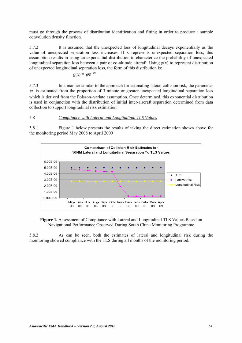
Asia/Pacific EMA Handbook – Version 2.0, August 2010 54
must go through the process of distribution identification and fitting in order to produce a sample convolution density function. 5.7.2 It is assumed that the unexpected loss of longitudinal decays exponentially as the value of unexpected separation loss increases. If x represents unexpected separation loss, this assumption results in using an exponential distribution to characterize the probability of unexpected longitudinal separation loss between a pair of co-altitude aircraft. Using g(x) to represent distribution of unexpected longitudinal separation loss, the form of this distribution is: g(x) = xe ϕϕ − 5.7.3 In a manner similar to the approach for estimating lateral collision risk, the parameter ϕ is estimated from the proportion of 3-minute or greater unexpected longitudinal separation loss which is derived from the Poisson–variate assumption. Once determined, this exponential distribution is used in conjunction with the distribution of initial inter-aircraft separation determined from data collection to support longitudinal risk estimation. 5.8 Compliance with Lateral and Longitudinal TLS Values 5.8.1 Figure 1 below presents the results of taking the direct estimation shown above for the monitoring period May 2008 to April 2009
Figure 1. Assessment of Compliance with Lateral and Longitudinal TLS Values Based on Navigational Performance Observed During South China Monitoring Programme
5.8.2 As can be seen, both the estimates of lateral and longitudinal risk during the monitoring showed compliance with the TLS during all months of the monitoring period.
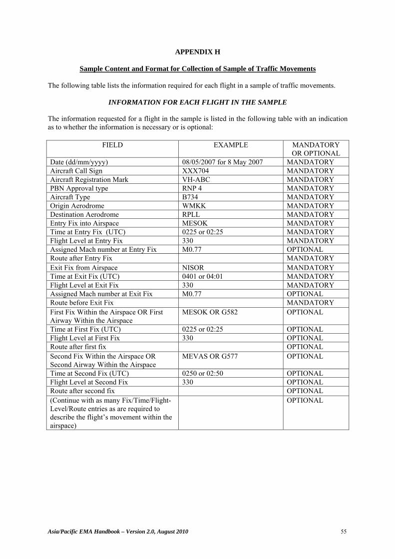
Asia/Pacific EMA Handbook – Version 2.0, August 2010 55
APPENDIX H
Sample Content and Format for Collection of Sample of Traffic Movements
The following table lists the information required for each flight in a sample of traffic movements.
INFORMATION FOR EACH FLIGHT IN THE SAMPLE
The information requested for a flight in the sample is listed in the following table with an indication as to whether the information is necessary or is optional:
FIELD EXAMPLE MANDATORY
OR OPTIONAL Date (dd/mm/yyyy) 08/05/2007 for 8 May 2007 MANDATORY Aircraft Call Sign XXX704 MANDATORY Aircraft Registration Mark VH-ABC MANDATORY PBN Approval type RNP 4 MANDATORY Aircraft Type B734 MANDATORY Origin Aerodrome WMKK MANDATORY Destination Aerodrome RPLL MANDATORY Entry Fix into Airspace MESOK MANDATORY Time at Entry Fix (UTC) 0225 or 02:25 MANDATORY Flight Level at Entry Fix 330 MANDATORY Assigned Mach number at Entry Fix M0.77 OPTIONAL Route after Entry Fix MANDATORY Exit Fix from Airspace NISOR MANDATORY Time at Exit Fix (UTC) 0401 or 04:01 MANDATORY Flight Level at Exit Fix 330 MANDATORY Assigned Mach number at Exit Fix M0.77 OPTIONAL Route before Exit Fix MANDATORY First Fix Within the Airspace OR First Airway Within the Airspace
MESOK OR G582 OPTIONAL
Time at First Fix (UTC) 0225 or 02:25 OPTIONAL Flight Level at First Fix 330 OPTIONAL Route after first fix OPTIONAL Second Fix Within the Airspace OR Second Airway Within the Airspace
MEVAS OR G577 OPTIONAL
Time at Second Fix (UTC) 0250 or 02:50 OPTIONAL Flight Level at Second Fix 330 OPTIONAL Route after second fix OPTIONAL (Continue with as many Fix/Time/Flight-Level/Route entries as are required to describe the flight’s movement within the airspace)
OPTIONAL
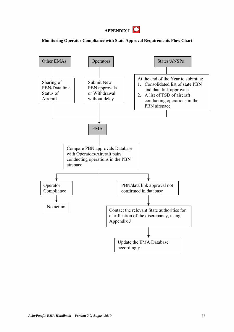
Asia/Pacific EMA Handbook – Version 2.0, August 2010 56
APPENDIX I
Monitoring Operator Compliance with State Approval Requirements Flow Chart
Other EMAs Operators States/ANSPs
EMA
Sharing of PBN/Data link Status of Aircraft
Submit New PBN approvals or Withdrawal without delay
At the end of the Year to submit a: 1. Consolidated list of state PBN
and data link approvals. 2. A list of TSD of aircraft
conducting operations in the PBN airspace.
Compare PBN approvals Database with Operators/Aircraft pairs conducting operations in the PBN airspace
Operator Compliance
PBN/data link approval not confirmed in database
No action Contact the relevant State authorities for clarification of the discrepancy, using Appendix J
Update the EMA Database accordingly
Stephanie.Beritsky
Sticky Note
Figure 3-2 Figure 3-2. Includes "Consolidated list of State PBC/PBN/PBS approvals"
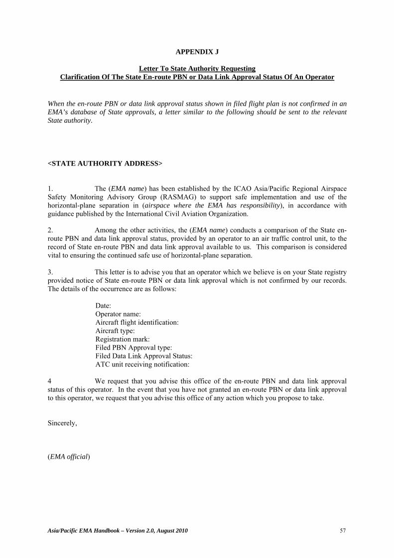
Asia/Pacific EMA Handbook – Version 2.0, August 2010 57
APPENDIX J
Letter To State Authority Requesting Clarification Of The State En-route PBN or Data Link Approval Status Of An Operator
When the en-route PBN or data link approval status shown in filed flight plan is not confirmed in an EMA’s database of State approvals, a letter similar to the following should be sent to the relevant State authority.
<STATE AUTHORITY ADDRESS> 1. The (EMA name) has been established by the ICAO Asia/Pacific Regional Airspace Safety Monitoring Advisory Group (RASMAG) to support safe implementation and use of the horizontal-plane separation in (airspace where the EMA has responsibility), in accordance with guidance published by the International Civil Aviation Organization.
2. Among the other activities, the (EMA name) conducts a comparison of the State en-route PBN and data link approval status, provided by an operator to an air traffic control unit, to the record of State en-route PBN and data link approval available to us. This comparison is considered vital to ensuring the continued safe use of horizontal-plane separation. 3. This letter is to advise you that an operator which we believe is on your State registry provided notice of State en-route PBN or data link approval which is not confirmed by our records. The details of the occurrence are as follows: Date: Operator name: Aircraft flight identification: Aircraft type: Registration mark: Filed PBN Approval type: Filed Data Link Approval Status: ATC unit receiving notification: 4 We request that you advise this office of the en-route PBN and data link approval status of this operator. In the event that you have not granted an en-route PBN or data link approval to this operator, we request that you advise this office of any action which you propose to take. Sincerely, (EMA official)
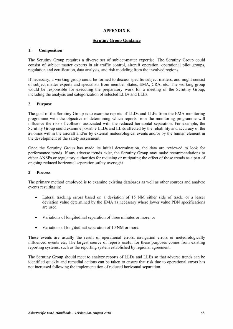
Asia/Pacific EMA Handbook – Version 2.0, August 2010 58
APPENDIX K
Scrutiny Group Guidance
1. Composition
The Scrutiny Group requires a diverse set of subject-matter expertise. The Scrutiny Group could consist of subject matter experts in air traffic control, aircraft operation, operational pilot groups, regulation and certification, data analysis, and risk modeling from the involved regions.
If necessary, a working group could be formed to discuss specific subject matters, and might consist of subject matter experts and specialists from member States, EMA, CRA, etc. The working group would be responsible for executing the preparatory work for a meeting of the Scrutiny Group, including the analysis and categorization of selected LLDs and LLEs.
2 Purpose
The goal of the Scrutiny Group is to examine reports of LLDs and LLEs from the EMA monitoring programme with the objective of determining which reports from the monitoring programme will influence the risk of collision associated with the reduced horizontal separation. For example, the Scrutiny Group could examine possible LLDs and LLEs affected by the reliability and accuracy of the avionics within the aircraft and/or by external meteorological events and/or by the human element in the development of the safety assessment.
Once the Scrutiny Group has made its initial determination, the data are reviewed to look for performance trends. If any adverse trends exist, the Scrutiny Group may make recommendations to either ANSPs or regulatory authorities for reducing or mitigating the effect of those trends as a part of ongoing reduced horizontal separation safety oversight.
3 Process
The primary method employed is to examine existing databases as well as other sources and analyze events resulting in:
• Lateral tracking errors based on a deviation of 15 NM either side of track, or a lesser deviation value determined by the EMA as necessary where lower value PBN specifications are used
• Variations of longitudinal separation of three minutes or more; or
• Variations of longitudinal separation of 10 NM or more.
These events are usually the result of operational errors, navigation errors or meteorologically influenced events etc. The largest source of reports useful for these purposes comes from existing reporting systems, such as the reporting system established by regional agreement.
The Scrutiny Group should meet to analyze reports of LLDs and LLEs so that adverse trends can be identified quickly and remedial actions can be taken to ensure that risk due to operational errors has not increased following the implementation of reduced horizontal separation.

Asia/Pacific EMA Handbook – Version 2.0, August 2010 59
4 Analysis and Methodology
The working group is tasked to analyse the reports of interest and examine the category assigned to each event. The event categories can be found in the EMA handbook, Appendix E.
The working group relies on its expert judgment and operational experience to analyse these reports. Upon completion of their preliminary analysis, the working group will present the results to the Scrutiny Group.
The Scrutiny Group shall examine its working group’s analysis results and take follow-up action as required.
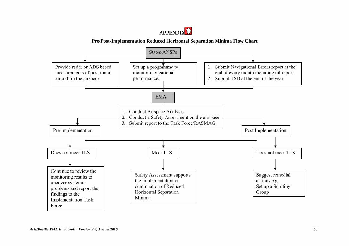
Asia/Pacific EMA Handbook – Version 2.0, August 2010 60
APPENDIX L
Pre/Post-Implementation Reduced Horizontal Separation Minima Flow Chart
States/ANSPs
Set up a programme to monitor navigational performance.
Provide radar or ADS based measurements of position of aircraft in the airspace
EMA
1. Conduct Airspace Analysis 2. Conduct a Safety Assessment on the airspace 3. Submit report to the Task Force/RASMAG
Meet TLS Does not meet TLS
Safety Assessment supports the implementation or continuation of Reduced Horizontal Separation Minima
Suggest remedial actions e.g. Set up a Scrutiny Group
1. Submit Navigational Errors report at the end of every month including nil report.
2. Submit TSD at the end of the year
Pre-implementation Post Implementation
Does not meet TLS
Continue to review the monitoring results to uncover systemic problems and report the findings to the Implementation Task Force
Stephanie.Beritsky
Sticky Note
Figure 3-1
Doc 10063 AN/524
Manual on Monitoring the
Application of Performance-
Based Horizontal Separation
Minima
NOTICE TO USERS This document is an unedited version of an ICAO publication and has not yet been approved in final form. As its content may still be supplemented, removed, or otherwise modified during the editing process, ICAO shall not be responsible whatsoever for any costs or liabilities incurred as a result of its use.
First Edition (advance unedited) — 2016
International Civil Aviation Organization
(ii)
Published in separate Arabic, Chinese, English, French, Russian and Spanish editions by the INTERNATIONAL CIVIL AVIATION ORGANIZATION 999 Boulevard Robert-Bourassa, Montréal, Quebec, Canada H3C 5H7
For ordering information and for a complete listing of sales agents and booksellers, please go to the ICAO website at www.icao.int.
Advance edition (unedited)
ICAO Doc 10063, Manual on Monitoring the Application of Performance-Based Horizontal Separation Minima Order Number: 10063 ISBN [TBD]
© ICAO 2016
All rights reserved. No part of this publication may be reproduced, stored in a retrieval system or transmitted in any form or by any means, without prior permission in writing from the International Civil Aviation Organization.

(iii)
AMENDMENTS
Amendments are announced in the supplements to the Catalogue of ICAO Publications; the Catalogue and its supplements are available on the ICAO website at www.icao.int. The space below is provided to keep a record of such amendments.
RECORD OF AMENDMENTS AND CORRIGENDA
AMENDMENTS No. Date
applicable Date
entered Entered by
CORRIGENDA No. Date
applicable Date
entered Entered by
(iv)
TABLE OF CONTENTS
Page
FOREWORD.................................................................................................................................... xi
Chapter 1. DEFINITIONS ....................................................................................................... 1-1
1.1 Terms and definitions .. ................................................................................................... 1-1 1.2 Acronyms ......................................................................................................................... 1-7
Chapter 2. DESCRIPTION OF THE FUNCTIONS NECESSARY TO MONITOR THE APPLICATION OF PERFORMANCE-BASED HORIZONTAL SEPARATION MINIMA ...................................................................................... 2-1
2.1 Description ....................................................................................................................... 2-1 2.2 Duties and Responsibilities for Monitoring the Application of Performance-based Horizontal Separation Minima ......................................................................................... 2-1 2.3 Process for Establishing the Functions Necessary to Monitor the Application of Performance-based Horizontal Separation Minima ......................................................... 2-2 Chapter 3. RESPONSIBILITIES AND STANDARDIZED PRACTICES .......................... 3-1
3.1 Purpose of this chapter ..................................................................................................... 3-1 3.2 Establishing the Competence Necessary to Conduct a Safety Assessment in a Region .. 3-2 3.3 Responsibilities and Standardized Practices for the Pre-Implementation Phase ............. 3-3 3.3.1 Review of operational concept ............................................................................ 3-3 3.3.2 Steps for conducting a pre-implementation safety assessment ........................... 3-3 3.4 Responsibilities and Standardized Practices for both Pre-Implementation and Post- Implementation Phases .................................................................................................... 3-5 3.4.1. Establishment and maintenance of database of performance-based operational approvals .......................................................................................... 3-5 3.4.2 Monitoring of operator compliance with State approval requirements ............... 3-6 3.4.3 Monitoring of communication, navigation, and surveillance performance ........ 3-8 3.4.3.1 General ................................................................................................. 3-8 3.4.3.2 Monitoring core navigational performance ......................................... 3-8 3.4.3.3 Monitoring longitudinal performance – speed variation ..................... 3-8 3.4.3.4 Monitoring of large lateral deviations (LLDs) and large longitudinal errors (LLEs) ................................................................... 3-9 3.4.3.5 Communication and surveillance performance monitoring ................. 3-10 3.4.4 Conducting safety assessments and reporting results ......................................... 3-10 3.4.4.1 Assembling a sample of traffic movements from the airspace ............ 3-10 3.4.4.2 Safety assessment ................................................................................ 3-11 3.4.4.3 Determining whether the safety assessment satisfies the TLS ............ 3-12 3.4.4.4 Remedial actions .................................................................................. 3-13
(v)
List of Figures Figure 3–1. Pre/post-implementation horizontal separation minima flow chart ......................... 3-2 Figure 3–2. Monitoring of operator compliance with State approval requirements flow chart... 3-7
List of Tables Table 3–1. Steps for conducting a safety assessment ................................................................. 3-4
Appendices Appendix A MANAGING PERFORMANCE-BASED OPERATIONAL APPROVALS .... A-1
A.1 Forms for use in obtaining records of performance-based operational approvals from a State authority .................................................................................................................. A-1 A.1.1 General – forms ................................................................................................... A-1 A.1.2 Point of contact details for matters relating to State performance-based operational approvals .......................................................................................... A-3 A.1.3 Record of State performance-based operational approval .................................. A-4 A.1.4 Withdrawal of State performance-based operational approval ........................... A-6 A.1.5 Letter to State authority requesting clarification of the State performance-based operational approval status of an operator .......................................................... A-7 A.2 Minimal informational content for each State performance-based operational approval to be maintained in electronic form ................................................................................. A-8 A.2.1 Aircraft performance-based operational approvals data ..................................... A-8 A.2.2 Aircraft re-registration/operating status change data .......................................... A-10 A.2.3 Point of contact data ............................................................................................ A-10 A.2.4 Data exchange among monitoring organizations ................................................ A-11 A.2.4.1 General ................................................................................................. A-11 A.2.4.2 Data exchange procedures ................................................................... A-12 A.2.4.3 Exchange of aircraft approvals data ..................................................... A-12 A.2.4.4 Aircraft re-registration/operating status change data ........................... A-13 A.2.4.5 Exchange of contact data ..................................................................... A-14 A.2.4.6 Confirmed non-compliant information ................................................ A-15 A.2.4.7 Fixed parameters – reference data sources .......................................... A-16 Appendix B FORM FOR ATS UNIT MONTHLY REPORT OF LLD OR LLE ................. B-1 Appendix C SCRUTINY GROUP GUIDANCE ....................................................................... C-1
C.1 Composition ..................................................................................................................... C-1 C.2 Purpose ............................................................................................................................. C-1 C.3 Process ............................................................................................................................. C-1 C.4 Analysis and Methodology .............................................................................................. C-1
(vi)
Appendix D TRAFFIC SAMPLE DATA (TSD) FOR TRAFFIC MOVEMENTS ............... D-1 Appendix E EXAMPLE “KNOW YOUR AIRSPACE” ANALYSIS .................................... E-1
E.1 Introduction ...................................................................................................................... E-1 E.2 Background ...................................................................................................................... E-1 E.3 Characteristics of L642 and M771 ................................................................................... E-1 E.3.1 Operator profile ................................................................................................... E-1 E.3.2 Origin-destination aerodromes ............................................................................ E-3 E.3.3 Use of the RNAV routes ..................................................................................... E-4 E.3.4 Flight-level usage on L642 and M771 ................................................................ E-4 E.3.5 Operator/aircraft type combinations.................................................................... E-5 E.4 Summary .......................................................................................................................... E-6 Appendix F OVERVIEW OF PERFORMANCE-BASED HORIZONTAL COLLISION RISK MODELLING ASSUMPTION .................................................................. F-1
F.1 Longitudinal Collision Risk Model.................................................................................. F-1 F.1.1 General ................................................................................................................ F-1 F.1.2 Controller intervention buffer ............................................................................. F-2 F.1.2.1 ATC to pilot communication times ..................................................... F-2 F.1.2.2 Controller intervention buffer scenarios .............................................. F-3 F.1.3 Navigation performance ...................................................................................... F-4 F.1.4 Variation in aircraft speed ................................................................................... F-5 F.2 Lateral collision risk model ............................................................................................. F-6 F.2.1 General ............................................................................................................. F-6 F.2.2 Lateral path keeping performance, Py(Sy) ........................................................... F-6
F.2.3 Average absolute relative along-track speed of two aircraft, x ......................... F-7 F.2.4 Average absolute relative cross-track speed between aircraft pairs operating
on tracks nominally separated by Sy - )( ySy ..................................................... F-7 F.2.5 Same and opposite direction lateral occupancy – Ey(same) and Ey(opp) ............ F-7 Appendix G EXAMPLE SAFETY ASSESSMENT – SOUTH CHINA SEA COLLISION RISK MODEL AND SAFETY ASSESSMENT .................................................. G-1
G.1 Introduction ...................................................................................................................... G-1 G.2 Background ...................................................................................................................... G-1 G.3 Results of Data Collection ............................................................................................... G-3 G.4 Risk Assessment and Safety Oversight – Compliance with TLS Values ........................ G-5 G.5 Safety Assessment ........................................................................................................... G-8 G.5.1 General ................................................................................................................ G-8 G.5.2 Alternate longitudinal risk assessment using Hsu model .................................... G-9 G.5.3 Assumptions ........................................................................................................ G-10
(vii)
Appendix H EXAMPLE SAFETY ASSESSMENT – HORIZONTAL SEPARATION REDUCTION IN NEW YORK OCEANIC AIRSPACE ................................... H-1
H.1 Introduction ...................................................................................................................... H-1 H.2 Background ...................................................................................................................... H-1 H.3 Description of New York Oceanic Airspace .................................................................... H-2 H.4 Operators and Aircraft Types Eligible for the Reduced Horizontal Separation Minima . H-3 H.5 Safety Assessment Methodology ..................................................................................... H-4 H.5.1 General ................................................................................................................ H-4 H.5.2 Lateral collision risk model ................................................................................. H-5 H.5.3 Longitudinal risk model ...................................................................................... H-6 H.6 Data Sources Used for the Safety Assessment ................................................................. H-9 H.6.1 General ................................................................................................................ H-9 H.6.2 Safety databases .................................................................................................. H-9 H.6.3 Ocean21 archived data ........................................................................................ H-9 H.7 Examination of Proximate Aircraft Operations in New York Oceanic Airspace ............ H-9 H.8 Analysis of Data Retrieved from Safety Databases ......................................................... H-12 H.9 Aircraft Lateral Deviations .............................................................................................. H-13 H.10 Weather Deviations .......................................................................................................... H-15 H.11 Data Link Communication Performance ......................................................................... H-18 H.11.1 General ................................................................................................................ H-18 H.11.2 Data link time and continuity .............................................................................. H-19 H.11.3 Reported data link outages .................................................................................. H-23 H.11.4 Overdue ADS periodic reports ............................................................................ H-25 H.12 Ocean21 Decision-Support Features Important to the Application of the Reduced Horizontal Separation Standards ...................................................................................... H-26 H.13 Parameters for the Collision Risk Models ....................................................................... H-26 H.13.1 General ................................................................................................................ H-26 H.13.2 Parameters common to the lateral and longitudinal collision risk models .......... H-26 H.13.2.1 Aircraft length, wingspan and height - x, y and z ............................ H-26 H.13.2.2 Probability that two aircraft assigned to the same flight level are in vertical overlap: Pz(0) ................................................................ H-27 H.13.2.3 The average relative vertical speed of two aircraft assigned to the
same flight level: z ........................................................................... H-28 H.13.3 Parameters used only in estimation of lateral risk ............................................... H-28 H.13.3.1 Average absolute relative along-track speed of two aircraft as they
pass on parallel tracks - x .................................................................. H-28 H.13.3.2 Average absolute relative cross-track speed between aircraft pairs
operating on tracks nominally separated by Sy - )( ySy
.................... H-28 H.13.3.3 Same-and opposite-direction lateral occupancies – Ey(same) and Ey(opp) ................................................................................................. H-28 H.13.3.4 Probability that two aircraft lose planned 30 NM lateral separation – Py(30) ................................................................................................ H-29 H.13.4 Parameters used only in estimation of longitudinal risk ..................................... H-30 H.13.4.1 Assumed average ground speed of aircraft 1, V1, and aircraft 2, V2 .. H-30 H.13.4.2 Average aircraft wingspan or length – λxy .......................................... H-30 H.13.4.3 Scale parameter for the speed error distribution – λv .......................... H-30 H.13.4.4 ADS-C report interval – T ................................................................... H-30
(viii)
H.13.4.5 Controller intervention buffer – τ ........................................................ H-32 H.13.4.6 Cross-track and along-track position error distributions ..................... H-32 H.13.4.7 Number of aircraft pairs per hour, NP ................................................. H-32 H.13.4.8 Table of longitudinal collision risk parameters ................................... H-33 H.14 Estimation of Lateral Risk and Comparison to the TLS .................................................. H-33 H.15 Estimation of Longitudinal Risk and Comparison to the TLS ......................................... H-34
______________________
(ix)
FOREWORD
1. HISTORICAL BACKGROUND
1.1 The International Civil Aviation Organization (ICAO) noted that some States and regions either had implemented or planned to implement horizontal separation minima in procedurally controlled airspace based on published performance-based operations requirements. It was also noted that these States and regions had developed procedures and practices to support the ongoing safety of these implementations.
1.2 The 2011 publication of the first edition of ICAO Doc 9937 — Operating Procedures and
Practices for Regional Monitoring Agencies in Relation to the Use of a 300 m (1 000 ft) Vertical Separation Minimum Between FL 290 and FL 410 Inclusive provides guidance about establishing such procedures and practices to support ongoing safe use of the reduced vertical separation minimum (RVSM). It was noted that there was no comparable ICAO-provided guidance for monitoring the application of performance-based horizontal separation minima. Accordingly, the ICAO Separation and Airspace Safety Panel (SASP) set about developing a manual analogous to Doc 9937 as a means of assisting States and regions to standardize monitoring activities supporting performance-based horizontal separation minima.
1.3 This document is the result of the SASP work, and should be considered to be supporting material
to ICAO Doc 9859 — Safety Management Manual. The proactive safety performance monitoring and measurement guidance provided in this document can satisfy safety assurance requirements provided in ICAO Annex 19 — Safety Management. In developing the material contained herein, the SASP relied upon the experience of experts from its member States which had prior experience in developing relevant procedures and practices. In addition, Australia, New Zealand, Singapore and the United States contributed to this document, modified portions of the “Asia/Pacific Region En-Route Monitoring Agency (EMA) Handbook” which these States had authored. Contributions by other regions, agencies and organizations are anticipated as the document matures and experience is gained.
2. SCOPE AND PURPOSE
2.1 This manual provides guidance and information to facilitate uniform application of Standards and Recommended Practices (SARPs) contained in Annex 6 — Operation of Aircraft, Annex 8 — Airworthiness of Aircraft, Annex 11 — Air Traffic Services, Annex 19 — Safety Management, the provisions in the Procedures for Air Navigation Services — Air Traffic Management (PANS-ATM, Doc 4444) and, when necessary, the Regional Supplementary Procedures (Doc 7030).
2.2 This document is intended to assist groups of States or regions in describing the functionality
needed to monitor the safe application of performance-based horizontal separation minima in procedurally controlled airspace. The procedures for these separation minima apply performance-based navigation performance (PBN) contained in the Performance-based Navigation (PBN) Manual (Doc 9613) and performance-based communication and surveillance (PBCS) contained in the Performance-Based Communication and Surveillance (PBCS) Manual (Doc 9869).
2.3 The tasks as described in this manual for monitoring the application of performance-based
horizontal separation minima may refer to system performance monitoring functions described in ICAO Doc 9869.
2.4 States may also call on the expertise developed for monitoring the application of
performance-based horizontal separation minima, to assist in the implementation of new horizontal separation
(x)
minima. Such an approach, in conjunction with performance-based specifications, such as for area navigation (RNAV), required navigation performance (RNP), required communication performance (RCP) and required surveillance performance (RSP), would assist in globally harmonizing the implementation and application of horizontal separation minima.
2.5 This document applies to groups of States or regions applying performance-based horizontal
separation minima in an en-route environment where procedural separation minima are being applied. It is not intended for operations in terminal airspace or en-route environments where ATS surveillance services are provided, any organization intent upon supporting safe operations in these environments should obtain safety-assessment and monitoring guidance elsewhere.
2.6 This manual is organized as follows:
a) Chapter 1 provides provides terms, definitions and acronyms;
b) Chapter 2 describes the functions necessary to monitor the application of performance-based horizontal separation minima by means of a list of duties and responsibilities;
c) Chapter 3 provides specific guidance on the duties and responsibilities that support implementation of performance-based horizontal separation minima;
d) Appendix A provides guidance on managing the status of performance-based operational approvals, and includes forms for collecting information, maintaining the information in electronic form and seeking clarification on operational approval status of an Operator;
e) Appendix B provides a form for an ATS unit to provide a monthly report of large lateral deviations (LLDs) and large longitudinal errors (LLEs);
f) Appendix C provides guidance for examining LLDs and LLEs;
g) Appendix D provides the traffic sample data (TSD) to collect and use to characterize the airspace and traffic movements;
h) Appendix E provides an example of an analysis that characterizes the airspace and traffic movements to support monitoring the application of performance-based horizontal separation minima;
i) Appendix F provides and overview of collision risk modeling assumptions when assessing the application of performance-based horizontal separation minima; and
j) Appendix G and Appendix H provide example safety assessments for the application of performance-based horizontal separation minima.
2.7 This document does not specify how the monitoring functions for applying performance-based horizontal separation minima are implemented by a group of States or region. The functions performed may be contained within a single organization or may be assigned to different working groups within the region. It is nevertheless recommended that the organization providing monitoring functions reports directly to a regional safety oversight group which is charged with monitoring overall system performance in light of regional safety goals. In turn, this safety oversight group reports either to the authorized planning and implementation regional group (PIRG) or the regional airspace safety group (RASG). For example, in the North Atlantic Region, the NAT Central Monitoring Agency (CMA) reports to the NAT Safety Oversight Group (SOG), which is authorized by the NAT Systems Planning Group (SPG). In the Asia/Pacific, several EMAs report to the Asia/Pacific Regional Airspace Safety Monitoring Advisory Group (RASMAG), which reports to the Asia/Pacific Air Navigation Planning and Implementation Regional Group (APANPIRG).
(xi)
3. REFERENCES
ICAO documents
Annex 6 — Operation of Aircraft Part I — International Commercial Air Transport — Aeroplanes Part II — International General Aviation — Aeroplanes Part III — International Operations — Helicopters
Annex 8 — Airworthiness of Aircraft Annex 11 — Air Traffic Services Annex 15 — Aeronautical Information Services Annex 19 — Safety Management Procedures for Air Navigation Services — Air Traffic Management (PANS-ATM, Doc 4444) Regional Supplementary Procedures (Regional SUPPs, Doc 7030) Designators for Aircraft Operating Agencies, Aeronautical Authorities and Services (Doc 8585) Aircraft Type Designators (Doc 8643) Manual on a 300 m (1 000 ft) Vertical Separation Minimum Between FL 290 and FL 410 Inclusive (Doc 9574) Performance-Based Navigation (PBN) Manual (Doc 9613) Manual on Airspace Planning Methodology for the Determination of Separation Minima (Doc 9689) Safety Management Manual (SMM) (Doc 9859) Performance-Based Communication and Surveillance (PBCS) Manual (Doc 9869) Operating Procedures and Practices for Regional Monitoring Agencies in Relation to the Use of a 300 m (1 000 ft) Vertical Separation Minimum Between FL 290 and FL 410 Inclusive (Doc 9937) Location Indicators (Doc 7910) Designators for Aircraft Operating Agencies, Aeronautical Authorities and Services (Doc 8585) Aircraft Type Designators (Doc 8643)
IATA documents
Airline Coding Directory
4. FUTURE DEVELOPMENTS
4.1 In order to keep this manual relevant and accurate, suggestions for improving it in terms of format, content or presentation are welcome. Any such recommendation or suggestion will be examined and, if found suitable, will be included in regular updates to the manual. Regular revision will ensure that the manual remains both pertinent and accurate. Comments on this manual should be addressed to:
The Secretary General International Civil Aviation Organization 999 Boulevard Robert-Bourassa Montréal, Quebec H3C 5H7 Canada
______________________

Doc 10063 1-1
Chapter 1. DEFINITIONS
1.1 TERMS AND DEFINITIONS
When the following terms are used in this document they have the following meanings.
Note.— Where the term has “(ICAO)” annotated, the term has already been defined as such in Annexes and Procedures for Air Navigation Services (PANS).
Term
ADS-C service. A term used to indicate an ATS service that uses ADS-C.
Note.— ICAO Doc 4444 does not include ADS-C in its definition for ATS surveillance system. Therefore, an ATS surveillance service does not consider those provided by means of the ADS-C application, unless it can be shown by comparative assessment to have a level of safety and performance equal to or better than monopulse SSR.
Aeronautical Information Publication (AIP). A publication issued by or with the authority of a State and containing aeronautical information of a lasting character essential to air navigation. (ICAO)
Air navigation services provider (ANSP). The organization(s) that operate(s) on behalf of a State to manage air traffic and airspace safely, economically and efficiently through the provision of facilities and seamless services in collaboration with all parties and involving airborne and ground-based functions.
Aircraft address. A unique combination of 24 bits available for assignment to an aircraft for the purpose of air-ground communications, navigation and surveillance. (ICAO)
Aircraft identification. A group of letters, figures or a combination thereof which is either identical to, or the coded equivalent of, the aircraft call sign to be used in air-ground communications, and which is used to identify the aircraft in ground-ground air traffic services communications. (ICAO)
Note 1.— The aircraft identification does not exceed 7 characters and is either the aircraft registration or the ICAO designator for the aircraft operating agency followed by the flight identification.
Note 2.— ICAO designators for aircraft operating agencies are contained in ICAO Doc 8585.
Aircraft registration. A group of letters, figures or a combination thereof which is assigned by the State of Registry to identify the aircraft.
Note.— Also referred to as registration marking.
Appropriate authority.
a) Regarding flight over the high seas: The relevant authority of the State of Registry.
Regarding flight other than over the high seas: The relevant authority of the State having sovereignty over the territory being overflown. (ICAO)
Area navigation (RNAV) specification. See navigation specification. (ICAO)
1-2 Doc 10063
Term
ATM operation. An individual operational component of air traffic services. Examples of ATM operations include the application of separation between aircraft, the re-routing of aircraft, and the provision of flight information.
ATS surveillance service. A term used to indicate a service provided directly by means of an ATS surveillance system. (ICAO)
ATS surveillance system. A generic term meaning variously, ADS-B, PSR, SSR or any comparable ground-based system that enables the identification of aircraft. (ICAO)
Note.— A comparable ground-based system is one that has been demonstrated, by comparative assessment or other methodology, to have a level of safety and performance equal to or better than monopulse SSR.
Automatic dependent surveillance — broadcast (ADS-B). A means by which aircraft, aerodrome vehicles and other objects can automatically transmit and/or receive data such as identification, position and additional data, as appropriate, in a broadcast mode via a data link. (ICAO)
Automatic dependent surveillance — contract (ADS-C). A means by which the terms of an ADS-C agreement will be exchanged between the ground system and the aircraft, via a data link, specifying under what conditions ADS-C reports would be initiated, and what data would be contained in the reports. (ICAO)
Note.— The abbreviated term “ADS contract” is commonly used to refer to ADS event contract, ADS demand contract, ADS periodic contract or an emergency mode.
Call sign. The designator used in air-ground communications to identify the aircraft and is equivalent to the encoded aircraft identification.
Collision risk. The expected number of midair collisions in a prescribed volume of airspace for a specific number of flight hours due to loss of planned separation.
Note.— One collision is considered to produce two accidents.
Controller-pilot data link communications (CPDLC). A means of communication between controller and pilot, using data link for ATC communications. (ICAO)
Core lateral navigational performance. That portion of overall lateral navigational performance which accounts for the bulk of observed lateral errors and which can be characterized by a single statistical distribution, usually symmetric about the mean lateral error with the frequency of increasing-magnitude errors decreasing at least exponentially.
Current flight plan. (See flight plan).
Data link initiation capability (DLIC). A data link application that provides the ability to exchange addresses, names and version numbers necessary to initiate data link applications. (ICAO)
Filed flight plan. (See flight plan).
Doc 10063 1-3
Term
Flight identification. A group of numbers, which is usually associated with an ICAO designator for an aircraft operating agency, to identify the aircraft in Item 7 of the flight plan.
Flight information region (FIR). An airspace of defined dimensions within which flight information service and alerting service are provided. (ICAO)
Flight plan. Specified information provided to air traffic services units, relative to an intended flight or portion of a flight of an aircraft. (ICAO)
A flight plan can take several forms, such as:
Current flight plan (CPL). The flight plan, including changes, if any, brought about by subsequent clearances. (ICAO)
Note 1.— When the word “message” is used as a suffix to this term, it denotes the content and format of the current flight plan data sent from one unit to another.
Filed flight plan (FPL). The flight plan as filed with an ATS unit by the pilot or a designated representative, without any subsequent changes. (ICAO)
Note 2.— When the word “message” is used as a suffix to this term, it denotes the content and format of the filed flight plan data as transmitted.
Aircraft active flight plan. The flight plan used by the flight crew. The sequence of legs and associated constraints that define the expected 3D or 4D trajectory of the aircraft from take-off to landing. (RTCA/EUROCAE)
Horizontal separation. The spacing provided between aircraft in the horizontal (lateral or longitudinal) plane to avoid collision.
Large lateral deviation (LLD). Any lateral deviation from the current flight plan track that is greater than a regionally agreed value pertinent to the applied separation minimum. One possibility for a region is to define an LLD as any lateral deviation with a magnitude at least two times the Required Navigation Performance (RNP) specification associated with the smallest lateral separation minimum possible. In airspace where RNP is not applicable, an LLD should be considered to be a lateral deviation with magnitude greater than or equal to half the lateral separation minimum.
Large longitudinal error (LLE). Any unexpected change in longitudinal separation between an aircraft pair, or for an individual aircraft the difference between an estimate for a given fix and the actual time of arrival over that fix, as applicable.
Note.— See Appendix B, which provides a form for reporting LLEs, and Appendix G for an example of criteria used by the Asia/Pacific Region.
Monitoring organization. A body that performs monitoring functions for the application of performance-based horizontal separation minima.
1-4 Doc 10063
Term
Navigation specification. A set of aircraft and aircrew requirements needed to support performance-based navigation operations within a defined airspace. There are two kinds of navigation specification:
RNAV specification. A navigation specification based on area navigation that does not include the requirement for on-board performance monitoring and alerting, designated by the prefix RNAV (e.g. RNAV 5, RNAV 1).
RNP specification. A navigation specification based on area navigation that includes the requirement for on-board performance monitoring and alerting, designated by the prefix RNP (e.g. RNP 4, RNP APCH).
Note.— Volume II of Doc 9613 contains detailed guidance on navigation specifications.
(Refer to the Performance-based Navigation (PBN) Manual (Doc 9613), 4th Edition, Volume 1 – Concept and Implementation Guidance, Explanation of Terms, page 1-(xviii)).
Occupancy. A parameter of the collision risk model which is twice the count of aircraft proximate pairs in a single dimension divided by the total number of aircraft flying the candidate paths in the same time interval.
Operational approval. An approval granted to the operator by a State authority after being satisfied that the operator meets specific aircraft and operational requirements.
Operational risk. The risk of collision due to operational errors and in-flight contingencies.
Overall risk. The risk of collision due to all causes, which includes the technical risk and the operational risk.
Passing frequency. The frequency of events in which the centers of mass of two aircraft are at least as close together as the metallic length of a typical aircraft when traveling in the same or opposite directions on adjacent routes separated by the lateral separation standard at the same flight level.
Performance-based communication (PBC). Communication based on performance specifications applied to the provision of air traffic services.
Note.— An RCP specification includes communication performance requirements that are allocated to system components in terms of communication transaction time, continuity, availability, integrity, safety and functionality needed for the proposed operation in the context of a particular airspace concept.
Performance-based navigation (PBN). Area navigation based on performance requirements for aircraft operating along an ATS route, on an instrument approach procedure or in a designated airspace. (ICAO)
Note.— Performance requirements are expressed in navigation specifications (RNAV specification, RNP specification) in terms of accuracy, integrity, continuity, availability and functionality needed for the proposed operation in the context of a particular airspace concept.
Doc 10063 1-5
Term
Performance-based surveillance (PBS). Surveillance based on performance applied to the provision of air traffic services.
Note.— An RSP specification includes surveillance performance requirements that are allocated to system components in terms of surveillance data delivery time, continuity, availability, integrity, accuracy of the surveillance data, safety and functionality needed for the proposed operation in the context of a particular airspace concept.
Procedural control. Term used to indicate that information derived from an ATS surveillance system is not required for the provision of air traffic control service. (ICAO)
Procedural separation. The separation used when providing procedural control. (ICAO)
Required communication monitored performance (RCMP). The maximum time against which ACP is assessed.
Required communication performance (RCP) specification. A set of requirements for air traffic service provision, aircraft capability, and operations needed to support performance-based communication.
Note.— The term RCP, currently defined as “a statement of performance requirements for operational communication in support of specific ATM functions”, has been revised to align the concept of PBC with the concept of PBN. The term RCP is now used in the context of a specification that is applicable to the prescription of airspace requirements, qualification of ATS provision, aircraft capability, and operational use, including post-implementation monitoring (e.g. RCP 240 refers to the criteria for various components of the operational system to ensure an acceptable intervention capability for the controller is maintained).
Required navigation performance (RNP) specification. See navigation specification. (ICAO)
Required surveillance monitored performance (RSMP). The maximum time against which ASP is assessed.
Required surveillance performance (RSP) specification. A set of requirements for air traffic service provision, aircraft capability, and operations needed to support performance-based surveillance.
Note.— The term RSP is used in the context of a specification that is applicable to the prescription of airspace requirements, qualification of ATS provision, aircraft capability, and operational use, including post-implementation monitoring (e.g. RSP 180 refers to the criteria for various components of the operational system to ensure an acceptable surveillance capability for the controller is maintained).
State of Design. The State having jurisdiction over the organization responsible for the type design. (ICAO)
State of Manufacture. The State having jurisdiction over the organization responsible for the final assembly of the aircraft. (ICAO)
1-6 Doc 10063
Term
State of Registry. The State on whose register the aircraft is entered. (ICAO)
Note.— In the case of the registration of aircraft of an international operating agency on other than a national basis, the States constituting the agency are jointly and severally bound to assume the obligations which, under the Chicago Convention, attach to a State of Registry. See, in this regard, the Council Resolution of 14 December 1967 on Nationality and Registration of Aircraft Operated by International Operating Agencies which can be found in Policy and Guidance Material on the Economic Regulation of International Air Transport (Doc 9587).
State of the Operator. The State in which the operator’s principal place of business is located or, if there is no such place of business, the operator’s permanent residence. (ICAO)
Target level of safety (TLS). A generic term representing the level of risk which is considered acceptable in particular circumstances.
Technical risk. The risk of collision associated with aircraft navigational performance.
Doc 10063 1-7
1.2 ACRONYMS
When the following acronyms are used in this document they have the following meanings. Where the term has “(ICAO)” annotated, the acronym has already been defined as such in Annexes and/or PANS.
Acronym Description
ADS-B Automatic dependent surveillance – broadcast
ADS-C Automatic dependent surveillance – contract
ANSP Air navigation services provider
ATC Air traffic control
ATM Air traffic management
ATS Air traffic services
CPDLC Controller-pilot data link communication
CRM Collision risk model
EMA En-route Monitoring Agency
FIR Flight information region
ICAO International Civil Aviation Organization
LLD Large lateral deviation
LLE Large longitudinal error
MASPS Minimum aviation system performance standard
NM Nautical miles
PBC Performance-based communication
PBCS Performance-based communication and surveillance
PBN Performance-based navigation
PBS Performance-based surveillance
PIRG Planning and Implementation Regional Group
RCP Required communication performance
1-8 Doc 10063
Acronym Description
RNAV Area navigation
RNP Required navigation performance
RSP Required surveillance performance
RVSM Reduced vertical separation minimum
SASP Separation and Airspace Safety Panel
SSR Secondary surveillance radar
TLS Target level of safety
TSD Traffic sample data
______________________
Doc 10063 2-1
Chapter 2. DESCRIPTION OF THE FUNCTIONS NECESSARY TO MONITOR THE
APPLICATION OF PERFORMANCE-BASED HORIZONTAL SEPARATION MINIMA
2.1 DESCRIPTION
2.1.1 Groups of States or regions establish a monitoring programme to support the safe use of performance-based horizontal separation minima. Effective provision of this programme relies heavily on safety data provided by States. Such data is contingent on a State having a safety management system mature enough to enable a robust safety reporting culture, providing data such as traffic samples, and importantly a means to investigate and develop controls and mitigations for risks identified through this process. Guidance on safety management principles is provided in the Safety Management Manual (SMM) (Doc 9859).
2.1.2 The functions defined in this chapter of the document directly support a region or State implementation of safety management principles through the pre-implementation assessment and ongoing performance monitoring of an airspace system. The airspace safety assessment and monitoring functionality enables a measurement of any practical drift from the system safety baseline following operational deployment. These functions should be undertaken using a combination of data collected through predictive, proactive and reactive means.
2.1.3 This document assumes that groups of States or ICAO regions establish a safety oversight group that is responsible for:
a) monitoring the safety of performance-based horizontal separation minima deployed in the region; and
b) taking action when the operational performance of the airspace, where such minima are deployed, has deviated significantly from the system design baseline.
2.1.4 The safety oversight group would, in turn, report periodically the status of separation-related safety to the region’s planning and implementation regional group (PIRG) or regional aviation safety group (RASG).
2.1.5 The safety oversight group would establish a programme for carrying out specific functions and duties to provide these monitoring services. The safety oversight group may establish a separate organization to provide these functions, or allocate these duties and responsibilities to existing groups within the existing PIRG sub-groups. These functions, duties and responsibilities are summarized in this chapter.
2.1.6 Within a region, these functions could be combined with the functions of the Regional Monitoring Agency (RMA), established to provide airspace safety assessment and monitoring services to support the continued safe use of the reduced vertical separation minimum (RVSM), and supported by other monitoring programmes, such as the performance-based communication and surveillance (PBCS) monitoring programme established by air navigation service providers detailed in the Performance- based Communication and Surveillance (PBCS) Manual (Doc 9869).
2.2 DUTIES AND RESPONSIBILITIES FOR MONITORING THE APPLICATION OF
PERFORMANCE-BASED HORIZONTAL SEPARATION MINIMA
2.2.1 The associated duties and responsibilities are:
a) to establish and maintain a database of operational approvals specific to the horizontal separation minima being applied in the airspace;
Stephanie.Beritsky
Sticky Note
1.1.1
Stephanie.Beritsky
Highlight
Stephanie.Beritsky
Sticky Note
1.2.1
Doc 10063 2-2
b) to receive reports of large horizontal deviations identified during monitoring, to take the necessary action with the relevant State authority and operator to determine the likely cause of the lateral deviation and/or longitudinal error, and to verify the approval status of the relevant operator;
c) to proactively undertake data collections as required by the regional oversight group which oversees
the safety of regional airspace to:
1) analyze data collected on a predictive and proactive basis to detect lateral and longitudinal deviation trends and, hence, to take action as specified in 2.1.3 b);
2) investigate the navigational performance of the aircraft in the core of the distribution of lateral deviations;
3) establish or add to databases of operational performance, including lateral navigation and/or communication and/or surveillance performance for: i) all flight operations; ii) operators/aircraft types; iii) individual airframes;
4) determine the appropriate method to monitor longitudinal errors;
d) to archive results of performance monitoring and to conduct periodic risk assessments that proactively identify aberrant changes in operational performance from agreed regional safety goals;
e) to initiate necessary remedial actions and coordinate with oversight groups as necessary in the light
of monitoring results; f) to monitor the level of risk as a consequence of operational errors and inflight contingencies
identified from a range of available safety data as follows:
1) determine, wherever possible, the root cause of each lateral deviation or longitudinal error together with its size and duration;
2) calculate the frequency of occurrence; 3) assess the overall risk in the system against the overall safety objectives; and 4) initiate remedial action as required;
g) to initiate checks of the approval status of aircraft operating in the relevant airspace, identify non-
approved operators and aircraft using the airspace and notify the appropriate State of Registry/State of the Operator accordingly; and
h) to submit reports as required to the PIRG/RASG through the region’s safety oversight group.
2.3 PROCESS FOR ESTABLISHING THE FUNCTIONS NECESSARY TO MONITOR THE
APPLICATION OF PERFORMANCE-BASED HORIZONTAL SEPARATION MINIMA
2.3.1 An organization should perform these functions either locally or on the basis of a bilateral, multilateral or regional air navigation agreement, as applicable, depending on the area of operations.
2.3.2 In order to effectively carry out the necessary duties and responsibilities, an acceptable level of competence must be demonstrated. Competence may be demonstrated by:
Stephanie.Beritsky
Sticky Note
1.3.1
Stephanie.Beritsky
Sticky Note
1.3.2
2-3 Doc 10063
a) previous airspace safety performance monitoring experience; or b) participation in ICAO technical panels or other bodies which develop horizontal separation
requirements or criteria for establishing separation minima based on performance-based operations; or
c) establishment of a formal relationship with an organization qualified under a) or b), resulting in the
latter organization being confident to provide an endorsement of the new organization as capable of carrying out the duties and responsibilities detailed in 2.2.
2.3.3 Once competence has been demonstrated, including presentation of sufficient material to the
regional oversight group on which to make a reasoned assessment, the safety oversight group and the PIRG should provide a formal approval.
2.3.4 Monitoring organizations should publish a list of flight information regions (FIRs) and/or ICAO Contracting States for which they provide monitoring services for application of performance-based horizontal separation minima.
______________________
Stephanie.Beritsky
Sticky Note
1.3.3
Stephanie.Beritsky
Sticky Note
1.3.4

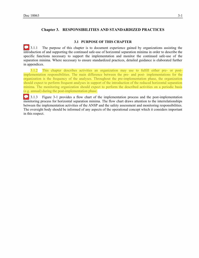
Doc 10063 3-1
Chapter 3. RESPONSIBILITIES AND STANDARDIZED PRACTICES
3.1 PURPOSE OF THIS CHAPTER
3.1.1 The purpose of this chapter is to document experience gained by organizations assisting the introduction of and supporting the continued safe-use of horizontal separation minima in order to describe the specific functions necessary to support the implementation and monitor the continued safe-use of the separation minima. Where necessary to ensure standardized practices, detailed guidance is elaborated further in appendices.
3.1.2 This chapter describes activities an organization may use to fulfill either pre- or post- implementation responsibilities. The main difference between the pre- and post- implementations for the organization is the frequency of the analyses. Throughout the pre-implementation phase, the organization should expect to perform frequent analyses in support of the introduction of the reduced horizontal separation minima. The monitoring organization should expect to perform the described activities on a periodic basis (e.g. annual) during the post-implementation phase.
3.1.3 Figure 3-1 provides a flow chart of the implementation process and the post-implementation monitoring process for horizontal separation minima. The flow chart draws attention to the interrelationships between the implementation activities of the ANSP and the safety assessment and monitoring responsibilities. The oversight body should be informed of any aspects of the operational concept which it considers important in this respect.
Stephanie.Beritsky
Sticky Note
2.7.2 and Appendix L
Stephanie.Beritsky
Sticky Note
2.1.1
Stephanie.Beritsky
Highlight
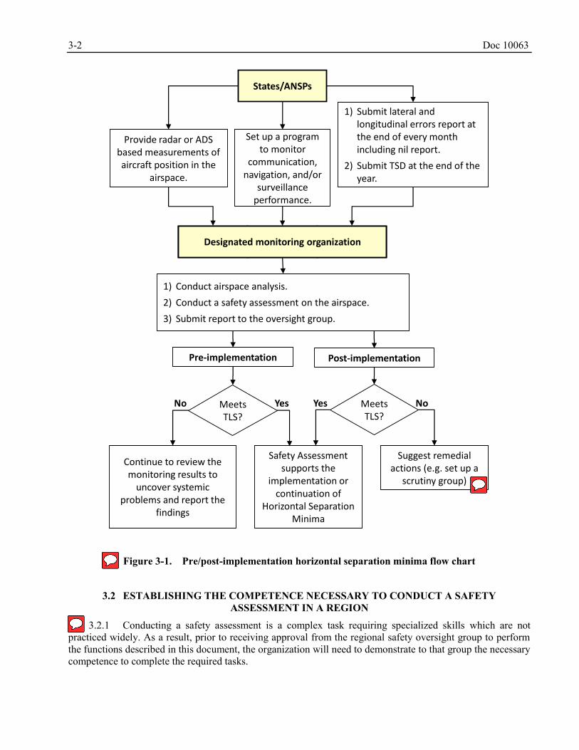
3-2 Doc 10063
States/ANSPs
Set up a program to monitor
communication, navigation, and/or
surveillance performance.
Provide radar or ADS based measurements of aircraft position in the
airspace.
Designated monitoring organization
1) Conduct airspace analysis.
2) Conduct a safety assessment on the airspace.
3) Submit report to the oversight group.
Safety Assessment supports the
implementation or continuation of
Horizontal Separation Minima
Suggest remedial actions (e.g. set up a
scrutiny group)
1) Submit lateral and longitudinal errors report at the end of every month including nil report.
2) Submit TSD at the end of the year.
Continue to review the monitoring results to
uncover systemic problems and report the
findings
Meets TLS?
Meets TLS?
Yes Yes NoNo
Pre-implementation Post-implementation
Figure 3-1. Pre/post-implementation horizontal separation minima flow chart
3.2 ESTABLISHING THE COMPETENCE NECESSARY TO CONDUCT A SAFETY
ASSESSMENT IN A REGION
3.2.1 Conducting a safety assessment is a complex task requiring specialized skills which are not practiced widely. As a result, prior to receiving approval from the regional safety oversight group to perform the functions described in this document, the organization will need to demonstrate to that group the necessary competence to complete the required tasks.
Stephanie.Beritsky
Sticky Note
There should be a scrutiny group established to review operational errors regardless of whether the TLS is met or not.
Stephanie.Beritsky
Sticky Note
2.4.4
Stephanie.Beritsky
Sticky Note
Appendix L
Doc 10063 3-3
3.2.2 Ideally, a monitoring organization will have the internal competence to conduct a safety assessment. However, recognizing that personnel with the required skills may not be available internally, a monitoring organization may find it necessary to augment its staff, through the use of personnel assigned by States to the regions planning and implementation groups, through arrangements with another established organization possessing the necessary competence.
3.2.3 If it is necessary to use another established organization to conduct a safety assessment, that organization must have the competence to judge that such an assessment is valid. This competence could be acquired through an arrangement with an organization with experience in conducting safety assessments.
3.2.4 The safety assessment must reflect the factors that influence collision risk within the airspace where the horizontal separation will be applied. Thus, a method to collect and organize pertinent data and other information descriptive of these airspace factors needs to be established. Data sources from other airspace where horizontal separation has been implemented may assist in conducting a safety assessment. However, these data may not be used as the sole justification for concluding that the TLS will be met in another airspace unless it is determined that the assumptions made in the safety assessment for the other airspace are applicable and valid for the relevant airspace.
3.2.5 When data from other airspace is used, a comparative safety assessment should be conducted to demonstrate that the assumptions made for the other airspace are valid for the relevant airspace. Basic airspace characteristics should be included in the comparative study, these include estimates of annual flying hours, number of flight operations, and traffic densities. The key assumptions to evaluate depend on capabilites, such as RCP, RSP and RNP/RNAV, and the specific reduced separation. For the relevant airspace, the comparative study should examine the observed system behavior, such as the CPDLC transaction times, data link outages and durations, and occurrences of navigational errors.
3.3 RESPONSIBILITIES AND STANDARDIZED PRACTICES FOR THE
PRE-IMPLEMENTATION PHASE
3.3.1 Review of operational concept
3.3.1.1 Experience has shown that the operational concept for the application of horizontal separation minima adopted by bodies overseeing these applications can substantially affect the collision risk in airspace.
3.3.1.2 The operational concept agreed by the body overseeing horizontal separation implementation, generally the ANSP, should be reviewed carefully with a view to identify any features of airspace use which may influence risk.
3.3.2 Steps for conducting a pre-implementation safety assessment
3.3.2.1 When implementing a performance-based horizontal separation minima, it is recommended to conduct a safety assessment in accordance with the requirements detailed in ICAO Annex 11 — Air Traffic Services (Chapter 2, section 2.27.5), ICAO Procedures for Air Navigation Services — Air Traffic Management (PANS-ATM, Doc 4444), (Chapter 2, Section 2.6), ICAO Annex 19 — Safety Management, and the supporting guidance material contained in the ICAO Safety Management Manual (SMM) (Doc 9859), including the development of hazard identification, risk management and mitigation procedures tables.
3.3.2.2 Table 3-1 provides an overview of the minimum steps considered necessary for a region to undertake a safety assessment. These steps are provided to describe the entire safety assessment process for the region. The monitoring organization should expect to participate in the process beginning with steps 3 and 4.
Stephanie.Beritsky
Sticky Note
2.7.1
Stephanie.Beritsky
Sticky Note
2.4.5
Stephanie.Beritsky
Sticky Note
2.4.6
Stephanie.Beritsky
Sticky Note
2.4.7
Stephanie.Beritsky
Highlight
Stephanie.Beritsky
Highlight
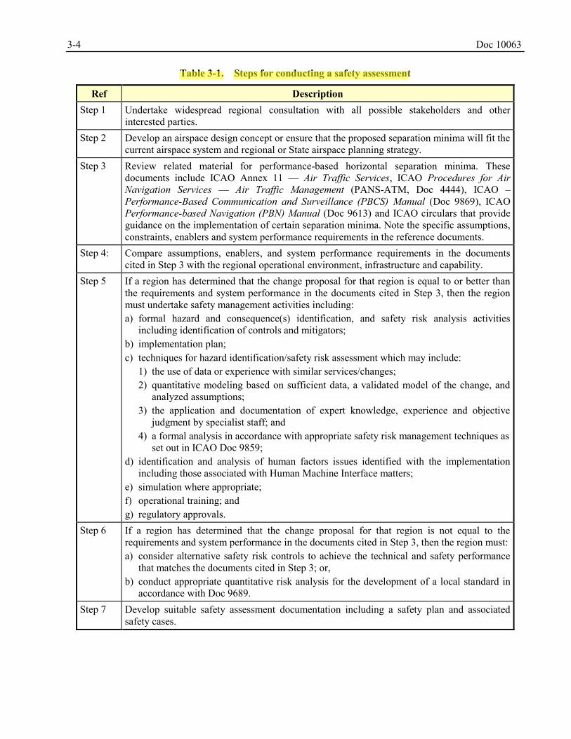
3-4 Doc 10063
Table 3-1. Steps for conducting a safety assessment
Ref Description Step 1 Undertake widespread regional consultation with all possible stakeholders and other
interested parties. Step 2 Develop an airspace design concept or ensure that the proposed separation minima will fit the
current airspace system and regional or State airspace planning strategy. Step 3 Review related material for performance-based horizontal separation minima. These
documents include ICAO Annex 11 — Air Traffic Services, ICAO Procedures for Air Navigation Services — Air Traffic Management (PANS-ATM, Doc 4444), ICAO –Performance-Based Communication and Surveillance (PBCS) Manual (Doc 9869), ICAO Performance-based Navigation (PBN) Manual (Doc 9613) and ICAO circulars that provide guidance on the implementation of certain separation minima. Note the specific assumptions, constraints, enablers and system performance requirements in the reference documents.
Step 4: Compare assumptions, enablers, and system performance requirements in the documents cited in Step 3 with the regional operational environment, infrastructure and capability.
Step 5 If a region has determined that the change proposal for that region is equal to or better than the requirements and system performance in the documents cited in Step 3, then the region must undertake safety management activities including: a) formal hazard and consequence(s) identification, and safety risk analysis activities
including identification of controls and mitigators; b) implementation plan; c) techniques for hazard identification/safety risk assessment which may include:
1) the use of data or experience with similar services/changes; 2) quantitative modeling based on sufficient data, a validated model of the change, and
analyzed assumptions; 3) the application and documentation of expert knowledge, experience and objective
judgment by specialist staff; and 4) a formal analysis in accordance with appropriate safety risk management techniques as
set out in ICAO Doc 9859; d) identification and analysis of human factors issues identified with the implementation
including those associated with Human Machine Interface matters; e) simulation where appropriate; f) operational training; and g) regulatory approvals.
Step 6 If a region has determined that the change proposal for that region is not equal to the requirements and system performance in the documents cited in Step 3, then the region must: a) consider alternative safety risk controls to achieve the technical and safety performance
that matches the documents cited in Step 3; or, b) conduct appropriate quantitative risk analysis for the development of a local standard in
accordance with Doc 9689. Step 7 Develop suitable safety assessment documentation including a safety plan and associated
safety cases.
Stephanie.Beritsky
Highlight
Doc 10063 3-5
Ref Description Step 8 Implementation activities should include:
a) trial under appropriate conditions; b) expert panel to undertake scrutiny of proposals and development of identified
improvements to the implementation plan; c) develop an appropriate backup plan to enable reversion if necessary; and d) continuous reporting and monitoring results of incidents, events, observations.
Step 9 Develop suitable post-implementation monitoring and review processes.
3.4 RESPONSIBILITIES AND STANDARDIZED PRACTICES FOR BOTH
PRE-IMPLEMENTATION AND POST-IMPLEMENTATION PHASES
3.4.1 Establishment and maintenance of database of performance-based operational approvals
3.4.1.1 The experience gained through the introduction of the RVSM has shown that the concept of utilizing monitoring organizations is effective in ensuring safety in a region. Monitoring organizations have a significant role to play in all aspects of the safety monitoring process. One of the functions for monitoring the application of performance-based horizontal separation minima is to establish a database of operators and aircraft types/systems approved for performance-based communications (PBC), performance-based navigation (PBN) and performance-based surveillance (PBS) operations by the appropriate authority. Guidance on these approvals is contained in Doc 9613 and Doc 9869.
3.4.1.2 Aviation is a global industry; many operators may be approved for performance-based operations and their approvals registered with an organization performing regional monitoring functions to support the application of horizontal separation minima that rely on performance-based operations. Thus, there is considerable opportunity for sharing the information from monitoring functions among the regions. A region or sub-region introducing horizontal separation predicated on performance-based specifications may need its own designated monitoring organization to act as a focal point for the collection and collation of approvals for aircraft operators operating solely in that region. However, because some aircraft operators may have approvals from States outside the region, the organization will need to coordinate with other regional monitoring organizations to determine the aircraft operator approval status.
3.4.1.3 To avoid duplication by States in registering approvals with any specific regional monitoring organization, the concept of a designated monitoring organization for processing approval data has been established. Under this concept, all States are associated with a specified designated monitoring organization for reporting performance-based operational approvals. Monitoring organizations should publish a list of ICAO Contracting States for which they provide monitoring services for application of performance-based horizontal separation minima. Designated monitoring organizations should contact the appropriate monitoring organization for a State, to address safety matters for operators registered with that State.
3.4.1.4 In airspace where implementation of performance-based separation is planned, not all aircraft may have the required approvals. Therefore, a State’s designated monitoring organization is required to establish a means to coordinate with the State authority to maintain a precise description of the approval information required. Appendix A, Section A.1 provides typical forms, with a brief description of their use, that can be transmitted to a State authority to obtain information on aircraft performance-based operational approval status.
3.4.1.5 To avoid duplication of work effort, wherever possible, any regional monitoring organization should collect State approval information from the regional monitoring organization associated with the State
Stephanie.Beritsky
Sticky Note
2.2.1
Stephanie.Beritsky
Sticky Note
2.2.2
Stephanie.Beritsky
Sticky Note
3.4.1.3
Stephanie.Beritsky
Sticky Note
2.2.4, 2.2.5
Stephanie.Beritsky
Sticky Note
2.2.6
3-6 Doc 10063
of the Operator. This collection will be facilitated if the regional monitoring organization maintains a database of these State approvals in a similar electronic form.
3.4.1.6 Appendix A, Section A.2 describes the minimum database content required, the format in which it should be maintained, a description of the data to be shared and procedures for data sharing.
3.4.2 Monitoring of operator compliance with State approval requirements
3.4.2.1 After the database described in Section 3.4.2 has been established, monitoring of operator compliance with State approval requirements should begin and be maintained while performance-based horizontal separation minima is being applied in the airspace. The aircraft approval status as listed in the data base is compared with the aircraft equipment and capability filed in the flight plan. This is required if State approval for performance-based operations is a prerequisite for applying the horizontal separation in such airspace.
3.4.2.2 Two sources of information are needed to perform this monitoring:
a) aircraft identification (Item 7), aircraft type (Item 9), aircraft registration and PBC, PBN, and/or PBS capability indicated in Items 10 and 18 of the flight plan; and
b) the database of State PBC, PBN, or PBS approval status, which is obtained from the State of the Operator or State of Registry.
3.4.2.3 As a minimum, compliance monitoring of the complete airspace for at least a 30-day period annually should be conducted. More frequent monitoring of operator approvals enables non-compliant operators to be efficiently identified and any risk associated with their operation in the airspace mitigated. Figure 3-2 provides a flow chart depicting the process required for monitoring of operator compliance with State approvals.
Stephanie.Beritsky
Sticky Note
2.5.1
Stephanie.Beritsky
Sticky Note
2.5.2
Stephanie.Beritsky
Sticky Note
2.5.3
Stephanie.Beritsky
Sticky Note
2.2.7
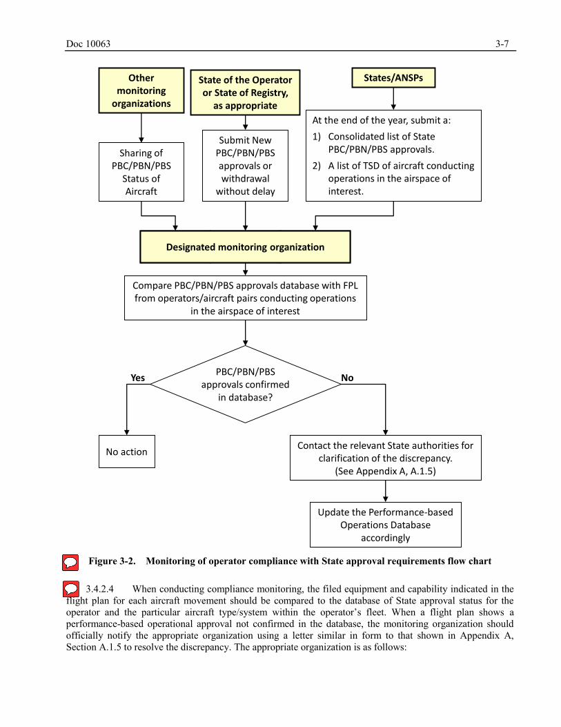
Doc 10063 3-7
Other monitoring
organizations
State of the Operator or State of Registry,
as appropriate
States/ANSPs
Sharing of PBC/PBN/PBS
Status of Aircraft
Submit New PBC/PBN/PBS approvals or withdrawal
without delay
At the end of the year, submit a:
1) Consolidated list of State PBC/PBN/PBS approvals.
2) A list of TSD of aircraft conducting operations in the airspace of interest.
Compare PBC/PBN/PBS approvals database with FPL from operators/aircraft pairs conducting operations
in the airspace of interest
No actionContact the relevant State authorities for
clarification of the discrepancy.(See Appendix A, A.1.5)
Update the Performance-based Operations Database
accordingly
Designated monitoring organization
PBC/PBN/PBS approvals confirmed
in database?
Yes No
Figure 3-2. Monitoring of operator compliance with State approval requirements flow chart
3.4.2.4 When conducting compliance monitoring, the filed equipment and capability indicated in the flight plan for each aircraft movement should be compared to the database of State approval status for the operator and the particular aircraft type/system within the operator’s fleet. When a flight plan shows a performance-based operational approval not confirmed in the database, the monitoring organization should officially notify the appropriate organization using a letter similar in form to that shown in Appendix A, Section A.1.5 to resolve the discrepancy. The appropriate organization is as follows:
Stephanie.Beritsky
Sticky Note
Appendix I
Stephanie.Beritsky
Sticky Note
2.5.4
3-8 Doc 10063
a) State of the Operator or State of Registry, as appropriate, if the State is assigned to the designated monitoring organization; or
b) the designated monitoring organization to which the State of the Operator or State of Registry is assigned.
3.4.2.5 The responsibility to take any action should an operator be found to have filed an incorrect declaration of State approval for performance-based operations lies clearly with the State authority, not the designated monitoring organization. The responsibility of the monitoring organization is only to officially notify the appropriate State authority of the discrepancy, and provide advice or information as requested by the State authority.
3.4.3 Monitoring of communication, navigation, and surveillance performance
3.4.3.1 General
3.4.3.1.1 The monitoring functions include the collection of information necessary to monitor communication, navigational and surveillance performance as part of the risk assessment. Procedures must be instituted to monitor core navigational performance, speed variations, related communication and surveillance performance, and to collect information descriptive of large lateral deviations (LLDs) and large longitudinal errors (LLEs).
3.4.3.2 Monitoring core navigational performance
3.4.3.2.1 As required by the regional oversight group, the navigational performance of the aircraft in the core of the distribution of lateral navigational accuracy by comparing aircraft reported position information with non-aircraft-generated position information such as radar data will be investigated. The analysis of core navigation performance contributes to the determination of lateral overlap probability used in conducting a safety assessment. Cooperation of States and ANSPs in monitoring horizontal core navigational performance through the use of appropriate ATS surveillance systems (e.g. secondary surveillance radar) must be enlisted. States and ANSPs have the responsibility to supply any requested data that will contribute to the evaluation of core navigational performance.
3.4.3.3 Monitoring longitudinal performance – speed variation
3.4.3.3.1 The safety assessment process will require evaluation of aircraft speed variation in the airspace. The analysis of aircraft speed variation contributes to the determination of horizontal overlap probability used in conducting a safety assessment. To accomplish this task, the cooperation of ANSPs must be enlisted in monitoring aircraft speed variation performance through the position reports and flight plan data, where appropriate. States and ANSPs have the responsibility to contribute to the analyses and supply any requested data that will contribute to the evaluation of longitudinal performance.
3.4.3.3.2 Aircraft speed variation can be monitored using aircraft position reports that contain estimates of next position. It may be necessary to utilize the instantaneous Mach speed information found in automatic dependent surveillance – contract (ADS-C) reports, and when appropriate the cleared Mach speed, to evaluate adherence to assigned Mach speed. The regional monitoring organization must institute procedures to monitor speed variations, related communication and surveillance performance, and to collect information descriptive of LLEs. Appendix F contains a description of the assumed speed variation distribution and other parameters used in the collision risk modeling.
Stephanie.Beritsky
Sticky Note
2.5.5
Stephanie.Beritsky
Sticky Note
2.3.1
Stephanie.Beritsky
Sticky Note
2.3.2
Stephanie.Beritsky
Highlight
Doc 10063 3-9
3.4.3.4 Monitoring of large lateral deviations (LLDs) and large longitudinal errors (LLEs)
3.4.3.4.1 Experience has shown that LLDs and LLEs have had significant influence on the outcome of safety assessments before implementation of performance-based separation minimum. Accordingly, a principal monitoring function is to ensure the existence of a programme to collect this information, assess the occurrences and initiate remedial action to correct systemic problems. Section 3.4.4.4 provides guidance for initiating such remedial actions as may be necessary to resolve systemic problems uncovered by this programme. One way to ensure the existence of such a programme is to develop letters of agreement between States.
3.4.3.4.2 Within the airspace for which it is responsible, each ANSP will need to establish the means to detect and report the occurrence of LLDs and LLEs. Experience has shown that the primary sources for reports of LLDs and LLEs are the ATS units providing air traffic control services in the airspace where the performance-based separation will be applied. The surveillance information available to these units – in the form of voice reports or ADS-C reports and, where available, surveillance radar data or automatic dependent surveillance – broadcast (ADS-B) data – provide the basis for identifying LLDs and LLEs.
3.4.3.4.3 A programme to assess the occurrence of LLDs and LLEs may include a regional Scrutiny Group to support the monitoring functions. A Scrutiny Group is comprised of operational and technical subject matter experts that support the evaluation and classification of LLDs and LLEs to determine their applicability to the collision risk estimate and for other purposes. Guidance on the functions of a Scrutiny Group is contained in Appendix C.
3.4.3.4.4 The ANSP should provide reports of the occurrence of LLDs and LLEs where the magnitude of the deviation or error meets or exceeds the regionally agreed value. It is noted that several horizontal separation minima are available for application in oceanic and procedural airspace depending on the eligibility of the aircraft operator and the capability of the ATC support systems. The regionally agreed value for reporting LLDs and LLEs should be based on the smallest separation minima possible to relieve ATC from the responsibility of deciding whether a deviation or error occurred based on the RNP specification and the separation minima applied.
3.4.3.4.5 The ANSP should establish a programme for ATS units to provide monthly reports of LLDs and LLEs. An example format for these reports is shown in Appendix B. These reports should contain, as a minimum, the following information:
a) reporting unit;
b) location of deviation, either as latitude/longitude, ATS route waypoint or other ATC fix;
c) date and time of LLDs and LLEs;
d) sub-portion of airspace, such as established route system, if applicable;
e) aircraft identification (or call sign) and aircraft type;
f) actual flight level or altitude;
g) horizontal separation being applied;
h) size of deviation;
i) duration of large deviation;
j) cause of deviation;
k) any other traffic in potential conflict during deviation;
Stephanie.Beritsky
Sticky Note
2.3.3
Stephanie.Beritsky
Sticky Note
2.3.5
Stephanie.Beritsky
Sticky Note
2.3.4
Stephanie.Beritsky
Highlight
Stephanie.Beritsky
Sticky Note
2.3.6
3-10 Doc 10063
l) crew comments when notified of deviation;
m) fields 10 and 18 from the ICAO filed flight plan; and
n) remarks from ATS unit making report.
3.4.3.4.6 Other sources for reports of LLDs and LLEs should also be explored. A monitoring organization is encouraged to determine if operators within the airspace for which it is responsible are willing to share pertinent summary information from internal safety oversight databases. In addition, a monitoring organization should inquire about access to State databases of safety incident reports which may be pertinent to the airspace. Voluntary reporting safety databases should also be examined, where these are available, as possible sources of LLDs and LLEs incidents in the airspace for which it is responsible.
3.4.3.4.7 While a monitoring organization will be the recipient and archivist for reports of LLDs and LLEs, it is important to note that it alone cannot be expected to conduct all activities associated with a comprehensive programme to detect and report large horizontal deviations. Rather, the support of the regional oversight group overseeing the safety of separation minima, the ICAO Regional Office, appropriate implementation task forces, scrutiny groups or any other organization that can assist in the establishment of such a programme should be enlisted.
3.4.3.5 Communication and surveillance performance monitoring
3.4.3.5.1 Performance-based operations that are predicated on the performance of communication and surveillance systems, such as those used for controller-pilot data link communications (CPDLC), ADS-C and/or satellite voice (SATVOICE), require approvals to show initial compliance with performance specifications and post-implementation monitoring to show continued compliance. Means for obtaining initial approval and continued monitoring should be established prior to the introduction of reduced separation minimum. Guidance material for these initial approvals and establishing PBCS monitoring programmes is provided in ICAO Doc 9869. In the assessment of risk levels, it may be necessary to use data from PBCS monitoring programmes.
3.4.3.5.2 The safety assessment process will require evaluation of observed communication and surveillance system behavior, such as the following:
a) CPDLC uplink transit times;
b) overdue ADS-C reports;
c) uplink messages with no response or an UNABLE response; and
d) communication service provider outages and the effect on operations in the airspace.
3.4.4 Conducting safety assessments and reporting results
3.4.4.1 Assembling a sample of traffic movements from the airspace
3.4.4.1.1 Samples of traffic movement data should be collected for the entire airspace where the horizontal separation will be implemented. As a result, ANSPs providing services within the airspace are required to cooperate in providing this data.
3.4.4.1.2 In planning the timing and duration of a traffic movement data sample, the importance of capturing any periods of heavy traffic flow which might result from seasonal or other factors should be taken into account. The duration of any traffic sample should be at least 30 days, with a longer sample period left to
Stephanie.Beritsky
Sticky Note
2.4.8
Stephanie.Beritsky
Sticky Note
2.4.9
Stephanie.Beritsky
Highlight
Stephanie.Beritsky
Sticky Note
2.3.7
Stephanie.Beritsky
Sticky Note
2.3.8
Doc 10063 3-11
the judgment of the experts. As an example, by regional agreement, traffic sample data within the Asia/Pacific Region is collected by all States for the month of December each year for purposes of RVSM monitoring. During 2009, the Asia/Pacific Air Navigation Planning and Implementation Regional Group (APANPIRG) expanded the usage of this data under certain conditions to support regional implementations, including the horizontal separation minima.
3.4.4.1.3 The following information should be collected for each flight in the sample:
a) date of flight;
b) aircraft identification (or call sign), in standard ICAO format;
c) aircraft registration mark, if available;
d) PBC approval type;
e) PBN approval type;
f) PBS approval type;
g) aircraft type conducting the flight, as listed in the applicable edition of ICAO Aircraft Type Designators (Doc 8643);
h) origin aerodrome, as listed in the applicable edition of ICAO Location Indicators (Doc 7910);
i) destination aerodrome, as listed in the applicable edition of ICAO Doc 7910;
j) entry point (fix or latitude/longitude) into the airspace;
k) time (UTC) at entry point;
l) flight level (and assigned Mach number if available) at entry point;
m) route after entry point;
n) exit point from the airspace;
o) time (UTC) at exit point;
p) flight level (and assigned Mach number if available) at exit point;
q) route before exit fix; and
r) additional fix/time/flight-level/route combinations that the monitoring organization judges are necessary to capture the traffic movement characteristics of the airspace.
3.4.4.1.4 Where possible, in coordinating collection of the sample, it should be specified that information be provided in electronic form (for example, in a spreadsheet). Appendix D contains a sample specification for collection of traffic movement data in electronic form, where the entries in the first column may be used as column headings on a spreadsheet template.
3.4.4.1.5 Acceptable sources for the information required in a traffic movement sample could include one or more of the following: ATC observations, ATC automation system data, automated air traffic management system data and surveillance data such as SSR or ADS-B reports.
3.4.4.2 Safety assessment
3.4.4.2.1 A State, or a group of States within a region, may call on the expertise developed for monitoring the application of performance-based horizontal separation minima to assist in the implementation of new separation minima. In order to conduct an implementation safety assessment, an in-depth knowledge of
Stephanie.Beritsky
Sticky Note
2.4.1
Stephanie.Beritsky
Sticky Note
2.4.1.0
Stephanie.Beritsky
Sticky Note
2.4.11
Stephanie.Beritsky
Sticky Note
2.4.12
3-12 Doc 10063
the use of the airspace is needed. For example, knowledge of expected operators and aircraft types, traffic flows, typical meteorological effects (such as equatorial meteorological effects, location of jet stream, etc), within the airspace which the horizontal separation will be implemented will inform the safety assessment process. Experience has shown that such knowledge can be gained through acquisition of charts and other material describing the airspace, and through periodic collection and analysis of samples of traffic movements within the airspace. The collation and consideration of this information results in a Know Your Airspace (KYA) analysis that documents matters of relevance to the horizontal separation implementation being proposed. An example of a typical KYA analysis is included as Appendix E.
3.4.4.2.2 For some implementations of separation minima specified in Doc 4444, collision risk modeling is required when it is determined that the assumptions made when developing the separation standards are not representative for the area where the standards are being implemented. A safety assessment should include an estimate of the risk of collision associated with the horizontal separation standard and a comparison of this risk to the established regional TLS or other associated safety metrics. The safety assessment will utilize collision risk methodologies that complement the safety management system (SMS) processes that are in place within the region. Appendix F of this document contains a summary of the parameters used in the performance-based collision risk models for horizontal separation minima. Examples of internationally recognized Collision Risk Models (CRMs) used to support the development, implementation, and continued safe-use of horizontal separation minima are included in Appendix G and Appendix H of this document, and in Doc 9689. Appendix G and Appendix H contain example safety assessments for the South China Sea and New York oceanic airspace, respectively.
3.4.4.2.3 The regional safety oversight group will determine the safety reporting requirements (e.g. format and periodicity).
3.4.4.3 Determining whether the safety assessment satisfies the TLS
3.4.4.3.1 “Technical risk” is the term used to describe the risk of collision associated with aircraft performance. Some of the factors which contribute to technical risk are:
a) errors in aircraft communication, navigation and surveillance systems; and
b) aircraft equipment failures resulting in unmitigated deviation from the cleared flight path, including those where not following the required procedures further increases the risk.
3.4.4.3.2 “Operational risk” is the term used to describe the risk of collision due to operational errors and in-flight contingencies. The term “operational error” is used to describe any horizontal deviation of an aircraft from the correct flight path as a result of incorrect action by ATC or the flight crew. Examples of such actions include:
a) a flight crew misunderstanding an ATC clearance, resulting in the aircraft operating on a flight path other than that issued in the clearance;
b) ATC issuing a clearance which places an aircraft on a flight path where the separation minimum with other aircraft cannot be maintained;
c) a coordination failure between ATS units in the transfer of control responsibility for an aircraft, resulting in either no notification of the transfer or in transfer at an unexpected transfer point; and
d) weather deviation. Note.— these deviations may be instances where the aircraft captain initiates the manoeuvre using operational authority but without advising ATC, and are not necessarily deemed as being incorrect action. However, they still contribute to operational risk and should be reported.
Stephanie.Beritsky
Sticky Note
2.4.2
Stephanie.Beritsky
Sticky Note
2.4.3
Stephanie.Beritsky
Sticky Note
2.4.15
Stephanie.Beritsky
Sticky Note
2.4.16
Doc 10063 3-13
3.4.4.3.3 The TLS which must be satisfied is established by regional agreement and documented in the Regional Supplementary Procedures (Doc 7030). For example, the generic Asia/Pacific TLS is presently established, for each dimension (lateral, longitudinal and vertical), as 5 x 10⁻⁹ fatal accidents per flight hour due to loss of planned separation; however, specific TLS values may be determined by ICAO for application of a particular separation minimum.
3.4.4.4 Remedial actions
3.4.4.4.1 Remedial actions are those measures taken to remove causes of systemic problems associated with factors affecting the implementation of the performance-based horizontal separation minima. Remedial actions may be necessary to control or mitigate the causes of problems such as the following:
a) failure of an aircraft to comply with performance-based operation requirements;
b) aircraft operating practices resulting in LLDs and LLEs; and
c) operational errors.
3.4.4.4.2 Monitoring results should be periodically reviewed by the designated monitoring organization and the associated regional Scrutiny Group in order to determine if there is evidence of any recurring problems or adverse trends. Guidance on the functions of a Scrutiny Group is contained in Appendix C.
3.4.4.4.3 As a minimum, an annual review of reports of LLDs and LLEs should be conducted with a view toward uncovering systemic problems and initiating remedial action. Should such problems be identified, the findings should be reported to the body overseeing horizontal separation implementation, or to the regional oversight group charged with monitoring the safety of separation minima. Included in the report should be the details of LLDs and LLEs suggesting the root cause of the problem.
______________________
Stephanie.Beritsky
Sticky Note
2.4.17
Stephanie.Beritsky
Sticky Note
2.6.1
Stephanie.Beritsky
Sticky Note
2.6.2
Stephanie.Beritsky
Sticky Note
2.6.3

Doc 10063 A-1
Appendix A MANAGING PERFORMANCE-BASED OPERATIONAL APPROVALS
This appendix provides:
a) forms for use in obtaining records of performance-based operational approvals from a State authority (Section A.1); and
b) minimal informational content for each State performance-based operational approval to be maintained in electronic form (Section A.2).
FORMS FOR USE IN OBTAINING RECORDS OF PERFORMANCE-BASED A.1
OPERATIONAL APPROVALS FROM A STATE AUTHORITY
A.1.1 General - forms
A.1.1.1 The following forms are provided for the collection of essential information relating to State performance-based operational approvals:
a) point of contact details for matters relating to performance-based operational approvals (Section A.1.2);
b) record of State performance-based operational approval (Section A.1.3);
c) withdrawal of State performance-based operational approval (Section A.1.4); and
d) letter to State authority requesting clarification of the State performance-based operational approval status of an operator (Section A.1.5).
A.1.1.2 The following provides guidance to complete the forms provided in this appendix:
a) It is important to have an accurate record of a point of contact for any queries that might arise from the monitoring of horizontal separation. Recipients are therefore requested to include a completed form provided in Section A.1.2 with their first reply to the designated monitoring organization. Thereafter, there is no further requirement unless there has been a change to the information requested on the form.
b) The form provided in Section A.1.3 must be completed for each operator/aircraft granted a performance-based operational approval.
c) The form provided in Section A.1.4 must be completed and submitted immediately whenever a State of the Operator or State of Registry has cause to withdraw its performance-based operational approval for a specific aircraft type/system within a specific operator’s fleet.
d) Note.— the fields in the forms provided in Section A.1.3 and Section A.1.4 should be completed as indicated Table A-1.
e) The form provided in Section A.1.5 should be used to confirm the performance-based operational approval status that may be shown in a filed flight plan but not in the database of State approvals.
Stephanie.Beritsky
Sticky Note
Appendix C
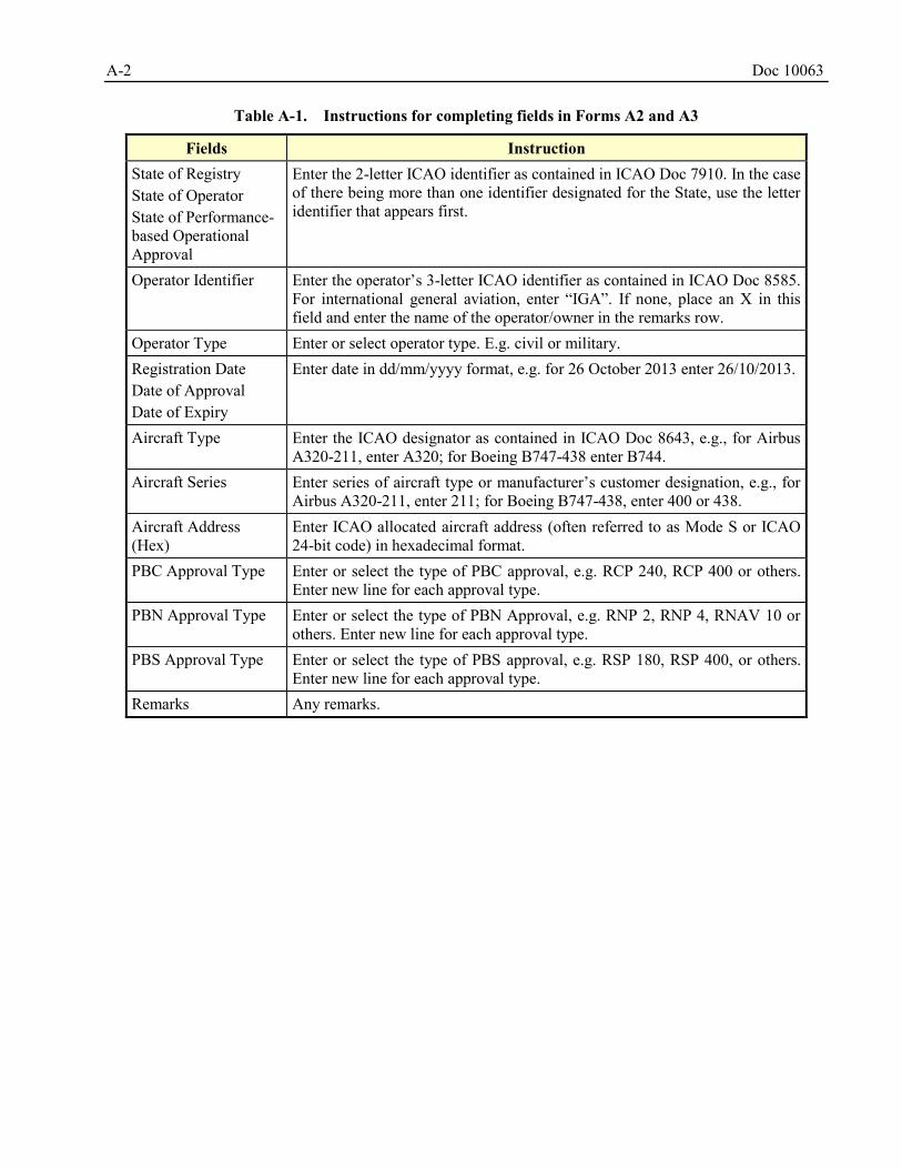
A-2 Doc 10063
Table A-1. Instructions for completing fields in Forms A2 and A3
Fields Instruction State of Registry State of Operator State of Performance-based Operational Approval
Enter the 2-letter ICAO identifier as contained in ICAO Doc 7910. In the case of there being more than one identifier designated for the State, use the letter identifier that appears first.
Operator Identifier Enter the operator’s 3-letter ICAO identifier as contained in ICAO Doc 8585. For international general aviation, enter “IGA”. If none, place an X in this field and enter the name of the operator/owner in the remarks row.
Operator Type Enter or select operator type. E.g. civil or military. Registration Date Date of Approval Date of Expiry
Enter date in dd/mm/yyyy format, e.g. for 26 October 2013 enter 26/10/2013.
Aircraft Type Enter the ICAO designator as contained in ICAO Doc 8643, e.g., for Airbus A320-211, enter A320; for Boeing B747-438 enter B744.
Aircraft Series Enter series of aircraft type or manufacturer’s customer designation, e.g., for Airbus A320-211, enter 211; for Boeing B747-438, enter 400 or 438.
Aircraft Address (Hex)
Enter ICAO allocated aircraft address (often referred to as Mode S or ICAO 24-bit code) in hexadecimal format.
PBC Approval Type Enter or select the type of PBC approval, e.g. RCP 240, RCP 400 or others. Enter new line for each approval type.
PBN Approval Type Enter or select the type of PBN Approval, e.g. RNP 2, RNP 4, RNAV 10 or others. Enter new line for each approval type.
PBS Approval Type Enter or select the type of PBS approval, e.g. RSP 180, RSP 400, or others. Enter new line for each approval type.
Remarks Any remarks.
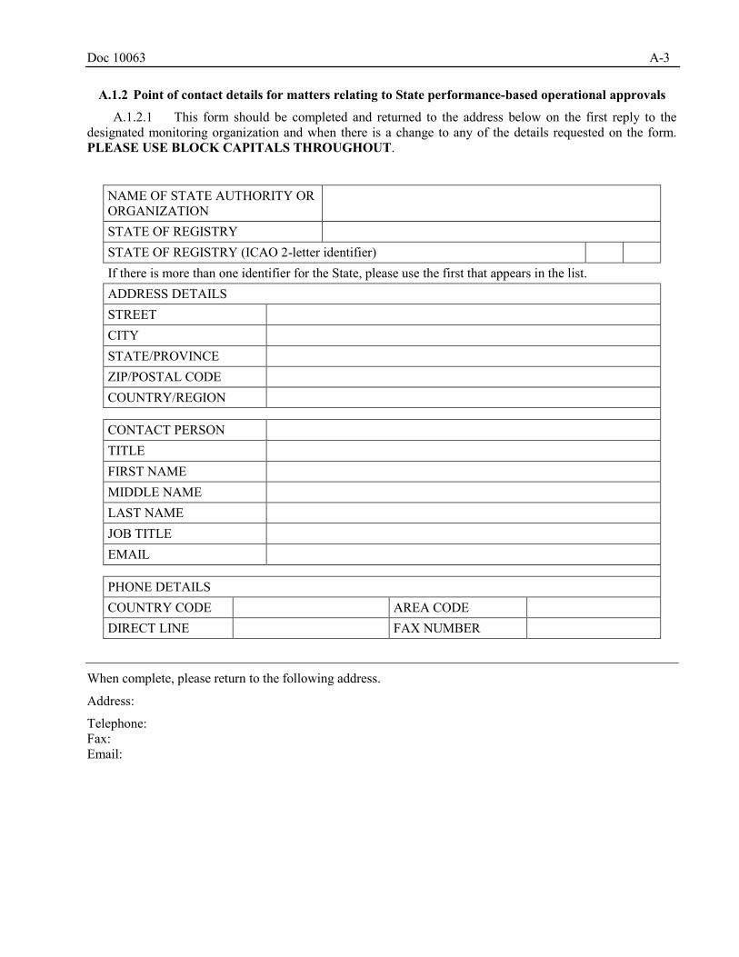
Doc 10063 A-3
A.1.2 Point of contact details for matters relating to State performance-based operational approvals
A.1.2.1 This form should be completed and returned to the address below on the first reply to the designated monitoring organization and when there is a change to any of the details requested on the form. PLEASE USE BLOCK CAPITALS THROUGHOUT.
NAME OF STATE AUTHORITY OR ORGANIZATION
STATE OF REGISTRY STATE OF REGISTRY (ICAO 2-letter identifier) If there is more than one identifier for the State, please use the first that appears in the list. ADDRESS DETAILS STREET CITY STATE/PROVINCE ZIP/POSTAL CODE COUNTRY/REGION
CONTACT PERSON TITLE FIRST NAME MIDDLE NAME LAST NAME JOB TITLE EMAIL
PHONE DETAILS COUNTRY CODE AREA CODE DIRECT LINE FAX NUMBER
When complete, please return to the following address.
Address:
Telephone: Fax: Email:
A-4 Doc 10063
A.1.3 Record of State performance-based operational approval
A.1.3.1 When a State of Registry approves or amends the approval of an operator/aircraft for State performance-based operations, details of that approval must be recorded and sent to the appropriate organization without delay.
A.1.3.2 Please refer to the accompanying notes on the following page before providing the information requested below. PLEASE USE BLOCK CAPITALS.
State of Registry: State of Operator: Operator Identifier: Name of Operator: Operator Type: * Civil / * Military (* delete as appropriate) Registration Date: Aircraft Type: Aircraft Series: Manufacturers Serial Number: Registration Mark: Aircraft Address (Hex): Number of Navigation System: Make/Model of Long Range Navigation System:
PBC/PBN/PBS Approval Type: PBC/PBN/PBS Time Limit: Date of Approval: Date of Expiry: Approval Authority (CAA): Approving CAA Official: Region for PBC/PBN/PBS Approval: State of PBC/PBN/PBS Approval: Status of Previous PBC/PBN/PBS Approval:
None Withdrawn
If withdrawn, please provide previous Registration Mark:
Remarks
When complete, please return to the following address.
Address:
Telephone: Fax: Email:
Doc 10063 A-5
Field Instruction State of Registry State of Operator State of Performance-based Operational Approval
Enter the 2-letter ICAO identifier as contained in ICAO Doc 7910. In the case of there being more than one identifier designated for the State, use the letter identifier that appears first.
Operator Identifier Enter the operator’s 3-letter ICAO identifier as contained in ICAO Doc 8585. For international general aviation, enter “IGA”. If none, place an X in this field and enter the name of the operator/owner in the remarks row.
Operator Type Enter or select operator type. E.g. civil or military. Registration Date Date of Approval Date of Expiry
Enter date in dd/mm/yyyy format, e.g. for 26 October 2013 enter 26/10/2013.
Aircraft Type Enter the ICAO designator as contained in ICAO Doc 8643, e.g., for Airbus A320-211, enter A320; for Boeing B747-438 enter B744.
Aircraft Series Enter series of aircraft type or manufacturer’s customer designation, e.g., for Airbus A320-211, enter 211; for Boeing B747-438, enter 400 or 438.
Aircraft Address (Hex)
Enter ICAO allocated aircraft address (often referred to as the Mode S or ICAO 24-bit code) in hexadecimal format.
PBC/PBN/PBS Approval Type
Enter or select the type of PBC/PBN/PBS approval, e.g. RCP 240, RCP 400, RNP 2, RNP 4, RNAV 10, RSP 180, RSP 400 or others. Enter new line for each approval type.
Remarks Any remarks.
A-6 Doc 10063
A.1.4 Withdrawal of State performance-based operational approval
A.1.4.1 When a State of Registry has cause to withdraw the State performance-based operational approval of an operator/aircraft, the details requested below must be sent to the designated monitoring organization without delay.
A.1.4.2 Please refer to the accompanying notes on the following page before providing the information requested. PLEASE USE BLOCK CAPITALS.
State of Registry: Operator Identifier: State of Operator: Aircraft Type: Aircraft Series: Manufacturers Serial Number: Registration Mark: Aircraft Address (Hex): Approval Withdrawn (PBC/PBN/PBS): Date of Withdrawal: PBC/PBN/PBS Withdrawn CAA Official: Reason for Withdrawal:
Fields Instruction State of Registry State of Operator
Enter the 2-letter ICAO identifier as contained in ICAO Doc 7910. In the case of there being more than one identifier designated for the State, use the letter identifier that appears first.
Operator Identifier Enter the operator’s 3-letter ICAO identifier as contained in ICAO Doc 8585. For international general aviation, enter “IGA”. If none, place an X in this field and enter the name of the operator/owner in the remarks row.
Date of Withdrawal Enter date in dd/mm/yyyy format, e.g. for 26 October 2013 enter 26/10/2013. Aircraft Type Enter the ICAO designator as contained in ICAO Doc 8643, e.g., for Airbus
A320-211, enter A320; for Boeing B747-438 enter B744. Aircraft Series Enter series of aircraft type or manufacturer’s customer designation, e.g., for
Airbus A320-211, enter 211; for Boeing B747-438, enter 400 or 438. Aircraft Address (Hex)
Enter ICAO allocated aircraft address (often referred to as the Mode S or ICAO 24-bit code) in hexadecimal format.
Approval Withdrawn Enter or select the type of PBC/PBN/PBS approval, e.g. RCP 240, RCP 400, RNP 2, RNP 4, RNAV 10, RSP 180, RSP 400 or others. Enter new line for each approval type.
Doc 10063 A-7
A.1.5 Letter to State authority requesting clarification of the State performance-based operational
approval status of an operator
When the State performance-based operational approval status shown in filed flight plan is not confirmed in the database of State approvals, a letter similar to the following should be sent to the relevant State authority.
<STATE AUTHORITY ADDRESS>
1. The (monitoring organization name) has been established by the ICAO (Appropriate group name e.g. Asia/Pacific Regional Airspace Safety Monitoring Advisory Group (RASMAG)) to support safe implementation and use of the horizontal separation in (airspace where the monitoring organization has responsibility), in accordance with guidance published by the International Civil Aviation Organization.
2. Among the other activities, the (monitoring organization name) conducts a comparison of the State performance-based operational approval status, provided by an operator to an air traffic control unit, to the record of State performance-based operational approval available to us. This comparison is considered vital to ensuring the continued safe use of horizontal separation.
3. This letter is to advise you that an operator which we believe is on your State registry provided notice of State performance-based operational approval which is not confirmed by our records. The details of the occurrence are as follows:
a) Date:
b) Operator name:
c) Aircraft identification (or call sign):
d) Aircraft type:
e) Filed performance-based operational approval type:
f) ATS unit receiving notification:
4. We request that you advise this office of the State performance-based operational approval status of this operator. In the event that you have not granted a State performance-based operational approval to this operator, we request that you advise this office of any action which you propose to take.
Sincerely,
(monitoring organization official)
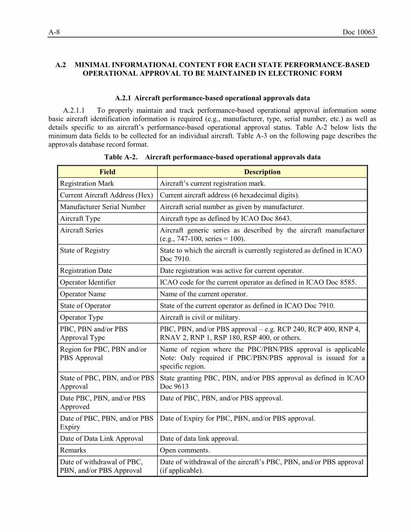
A-8 Doc 10063
MINIMAL INFORMATIONAL CONTENT FOR EACH STATE PERFORMANCE-BASED A.2
OPERATIONAL APPROVAL TO BE MAINTAINED IN ELECTRONIC FORM
A.2.1 Aircraft performance-based operational approvals data
A.2.1.1 To properly maintain and track performance-based operational approval information some basic aircraft identification information is required (e.g., manufacturer, type, serial number, etc.) as well as details specific to an aircraft’s performance-based operational approval status. Table A-2 below lists the minimum data fields to be collected for an individual aircraft. Table A-3 on the following page describes the approvals database record format.
Table A-2. Aircraft performance-based operational approvals data
Field Description Registration Mark Aircraft’s current registration mark. Current Aircraft Address (Hex) Current aircraft address (6 hexadecimal digits). Manufacturer Serial Number Aircraft serial number as given by manufacturer. Aircraft Type Aircraft type as defined by ICAO Doc 8643. Aircraft Series Aircraft generic series as described by the aircraft manufacturer
(e.g., 747-100, series = 100). State of Registry State to which the aircraft is currently registered as defined in ICAO
Doc 7910. Registration Date Date registration was active for current operator. Operator Identifier ICAO code for the current operator as defined in ICAO Doc 8585. Operator Name Name of the current operator. State of Operator State of the current operator as defined in ICAO Doc 7910. Operator Type Aircraft is civil or military. PBC, PBN and/or PBS Approval Type
PBC, PBN, and/or PBS approval – e.g. RCP 240, RCP 400, RNP 4, RNAV 2, RNP 1, RSP 180, RSP 400, or others.
Region for PBC, PBN and/or PBS Approval
Name of region where the PBC/PBN/PBS approval is applicable Note: Only required if PBC/PBN/PBS approval is issued for a specific region.
State of PBC, PBN, and/or PBS Approval
State granting PBC, PBN, and/or PBS approval as defined in ICAO Doc 9613
Date PBC, PBN, and/or PBS Approved
Date of PBC, PBN, and/or PBS approval.
Date of PBC, PBN, and/or PBS Expiry
Date of Expiry for PBC, PBN, and/or PBS approval.
Date of Data Link Approval Date of data link approval. Remarks Open comments. Date of withdrawal of PBC, PBN, and/or PBS Approval
Date of withdrawal of the aircraft’s PBC, PBN, and/or PBS approval (if applicable).
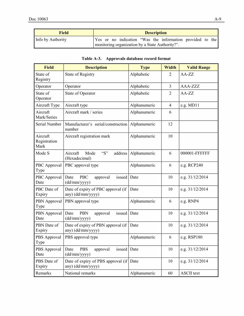
Doc 10063 A-9
Field Description Info by Authority Yes or no indication “Was the information provided to the
monitoring organization by a State Authority?”.
Table A-3. Approvals database record format
Field Description Type Width Valid Range State of Registry
State of Registry Alphabetic 2 AA-ZZ
Operator Operator Alphabetic 3 AAA-ZZZ State of Operator
State of Operator Alphabetic 2 AA-ZZ
Aircraft Type Aircraft type Alphanumeric 4 e.g. MD11 Aircraft Mark/Series
Aircraft mark / series Alphanumeric 6
Serial Number Manufacturer’s serial/construction number
Alphanumeric 12
Aircraft Registration Mark
Aircraft registration mark Alphanumeric 10
Mode S Aircraft Mode “S” address (Hexadecimal)
Alphanumeric 6 000001-FFFFFF
PBC Approval Type
PBC approval type Alphanumeric 6 e.g. RCP240
PBC Approval Date
Date PBC approval issued (dd/mm/yyyy)
Date 10 e.g. 31/12/2014
PBC Date of Expiry
Date of expiry of PBC approval (if any) (dd/mm/yyyy)
Date 10 e.g. 31/12/2014
PBN Approval Type
PBN approval type Alphanumeric 6 e.g. RNP4
PBN Approval Date
Date PBN approval issued (dd/mm/yyyy)
Date 10 e.g. 31/12/2014
PBN Date of Expiry
Date of expiry of PBN approval (if any) (dd/mm/yyyy)
Date 10 e.g. 31/12/2014
PBS Approval Type
PBS approval type Alphanumeric 6 e.g. RSP180
PBS Approval Date
Date PBS approval issued (dd/mm/yyyy)
Date 10 e.g. 31/12/2014
PBS Date of Expiry
Date of expiry of PBS approval (if any) (dd/mm/yyyy)
Date 10 e.g. 31/12/2014
Remarks National remarks Alphanumeric 60 ASCII text
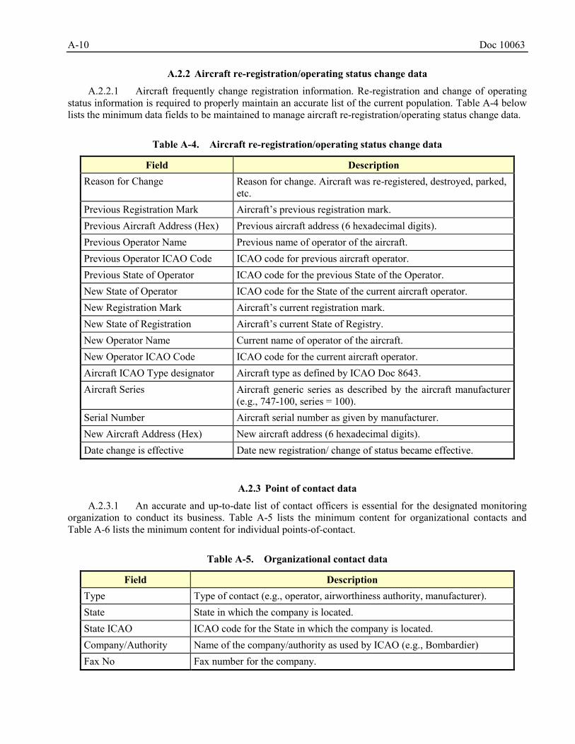
A-10 Doc 10063
A.2.2 Aircraft re-registration/operating status change data
A.2.2.1 Aircraft frequently change registration information. Re-registration and change of operating status information is required to properly maintain an accurate list of the current population. Table A-4 below lists the minimum data fields to be maintained to manage aircraft re-registration/operating status change data.
Table A-4. Aircraft re-registration/operating status change data
Field Description Reason for Change Reason for change. Aircraft was re-registered, destroyed, parked,
etc. Previous Registration Mark Aircraft’s previous registration mark. Previous Aircraft Address (Hex) Previous aircraft address (6 hexadecimal digits). Previous Operator Name Previous name of operator of the aircraft. Previous Operator ICAO Code ICAO code for previous aircraft operator. Previous State of Operator ICAO code for the previous State of the Operator. New State of Operator ICAO code for the State of the current aircraft operator. New Registration Mark Aircraft’s current registration mark. New State of Registration Aircraft’s current State of Registry. New Operator Name Current name of operator of the aircraft. New Operator ICAO Code ICAO code for the current aircraft operator. Aircraft ICAO Type designator Aircraft type as defined by ICAO Doc 8643. Aircraft Series Aircraft generic series as described by the aircraft manufacturer
(e.g., 747-100, series = 100). Serial Number Aircraft serial number as given by manufacturer. New Aircraft Address (Hex) New aircraft address (6 hexadecimal digits). Date change is effective Date new registration/ change of status became effective.
A.2.3 Point of contact data
A.2.3.1 An accurate and up-to-date list of contact officers is essential for the designated monitoring organization to conduct its business. Table A-5 lists the minimum content for organizational contacts and Table A-6 lists the minimum content for individual points-of-contact.
Table A-5. Organizational contact data
Field Description Type Type of contact (e.g., operator, airworthiness authority, manufacturer). State State in which the company is located. State ICAO ICAO code for the State in which the company is located. Company/Authority Name of the company/authority as used by ICAO (e.g., Bombardier) Fax No Fax number for the company.
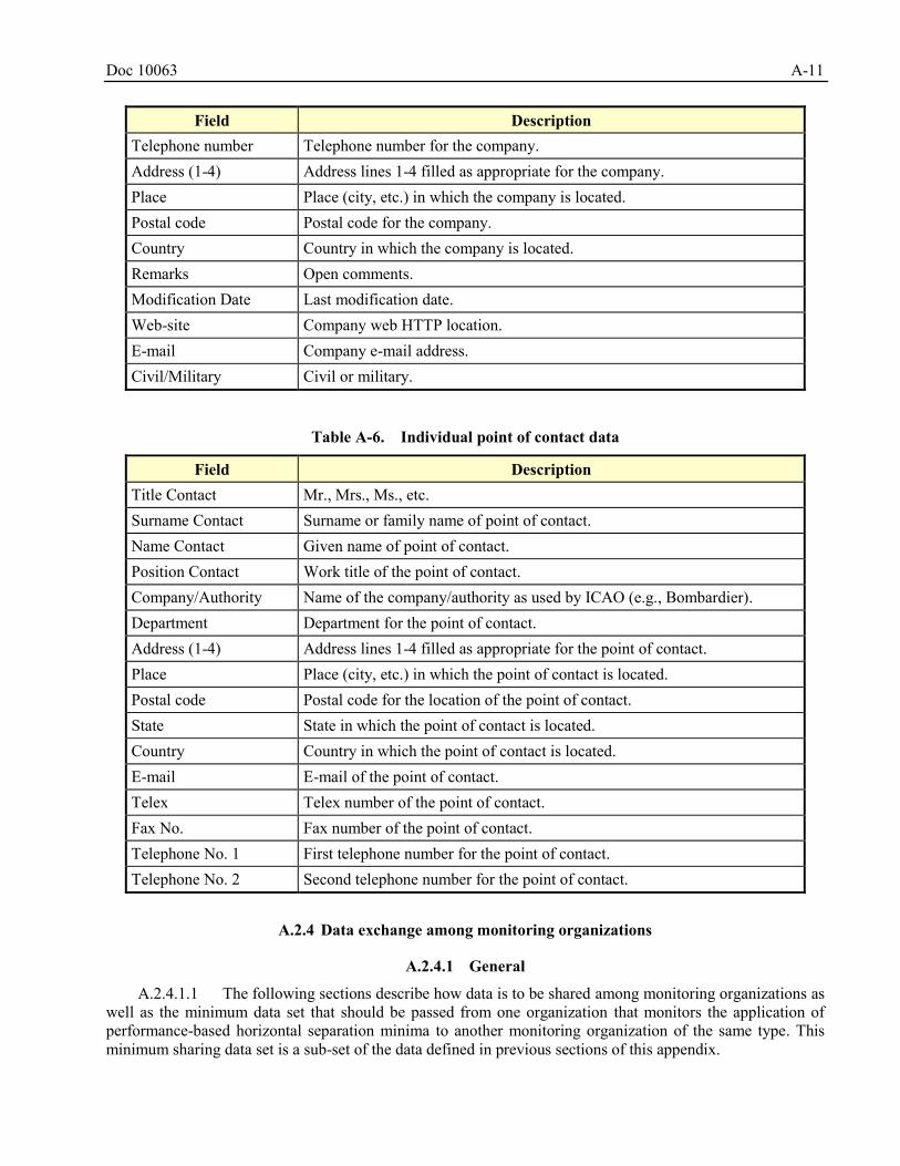
Doc 10063 A-11
Field Description Telephone number Telephone number for the company. Address (1-4) Address lines 1-4 filled as appropriate for the company. Place Place (city, etc.) in which the company is located. Postal code Postal code for the company. Country Country in which the company is located. Remarks Open comments. Modification Date Last modification date. Web-site Company web HTTP location. E-mail Company e-mail address. Civil/Military Civil or military.
Table A-6. Individual point of contact data
Field Description Title Contact Mr., Mrs., Ms., etc. Surname Contact Surname or family name of point of contact. Name Contact Given name of point of contact. Position Contact Work title of the point of contact. Company/Authority Name of the company/authority as used by ICAO (e.g., Bombardier). Department Department for the point of contact. Address (1-4) Address lines 1-4 filled as appropriate for the point of contact. Place Place (city, etc.) in which the point of contact is located. Postal code Postal code for the location of the point of contact. State State in which the point of contact is located. Country Country in which the point of contact is located. E-mail E-mail of the point of contact. Telex Telex number of the point of contact. Fax No. Fax number of the point of contact. Telephone No. 1 First telephone number for the point of contact. Telephone No. 2 Second telephone number for the point of contact.
A.2.4 Data exchange among monitoring organizations
A.2.4.1 General
A.2.4.1.1 The following sections describe how data is to be shared among monitoring organizations as well as the minimum data set that should be passed from one organization that monitors the application of performance-based horizontal separation minima to another monitoring organization of the same type. This minimum sharing data set is a sub-set of the data defined in previous sections of this appendix.
A-12 Doc 10063
A.2.4.1.2 All organizations receiving data have responsibility to help ensure data integrity. A receiving monitoring organization must report back to the sending monitoring organization any discrepancies or incorrect information found in the sent data.
A.2.4.2 Data exchange procedures
A.2.4.2.1 The standard mode of exchange shall be e-mail or FTP, with frequency of submission in accordance with Table A-7. Data shall be presented in Microsoft Excel or Microsoft Access.
A.2.4.2.2 The monitoring organization must be aware that the data are current only to the date of the created file.
Table A-7. Monitoring organization data exchange procedures
Data Type Data Subset Frequency When Performance-based Operational Approvals
All Monthly First week in month
Aircraft Re-registration/Status New since last broadcast Monthly First week in month Contact All Monthly First week in month Non-Compliant Aircraft All As required Immediate
A.2.4.2.3 In addition to regular data exchanges, one-off queries shall be made between monitoring organizations, as necessary. This includes requests for data in addition to the minimum exchanged data set such as service bulletin information.
A.2.4.3 Exchange of aircraft approvals data
A.2.4.3.1 Performance-based operational approval data shall be exchanged among monitoring organizations. Table A-8 below defines the fields required for sending a record to another monitoring organization.
Table A-8. Exchange of aircraft approvals data
Field Need to Share Registration Mark Mandatory Mode S Desirable Serial Number Desirable Aircraft Type Mandatory Aircraft Series Mandatory State of Registry Mandatory Registration date Desirable Operator Identifier Mandatory Operator Name Desirable State of Operator Mandatory
Doc 10063 A-13
Field Need to Share Civil or military indication (not a field on its own. It is indicated in the ICAO operator code as MIL except when the military has a code)
Desirable
State of PBC, PBN, and PBS approval Mandatory PBC approval types Mandatory Date PBC approved Mandatory Date of PBC approval expiry Mandatory PBN approval type Mandatory Date PBN approved Mandatory Date of PBN approval expiry Mandatory PBS approval types Mandatory Date PBS approved Mandatory Date of PBS approval expiry Mandatory Remarks No Date of withdrawal of PBC approval Mandatory Date of withdrawal of PBN approval Mandatory Date of withdrawal of PBS approval Mandatory Information by Authority Mandatory
A.2.4.4 Aircraft re-registration/operating status change data
A.2.4.4.1 All re-registration information as shown in Table A-9 shall be shared.
Table A-9. Exchange of aircraft re-registration/operating status change data
Field Need to Share Reason for change (i.e. re-registered, destroyed, parked)
Mandatory
Previous Registration Mark Mandatory Previous Mode S Desirable Previous Operator Name Desirable Previous Operator ICAO Code Mandatory Previous State of Operator Mandatory State of Operator Mandatory New Registration Mark Mandatory New State of Registration Mandatory New Operator Name Desirable
A-14 Doc 10063
Field Need to Share New Operator Code Desirable Aircraft ICAO Type Designator Mandatory Aircraft Series Mandatory Serial Number Mandatory New Mode S Mandatory Date change is effective Desirable
A.2.4.5 Exchange of contact data
A.2.4.5.1 All organization and individual point of contact data shall be shared in accordance with Table A-10 and Table A-11.
Table A-10. Exchange of organizational contact data fields
Field Need to Share Type Mandatory State Mandatory State ICAO Desirable Company/Authority Mandatory Fax No. Desirable Telephone No. Mandatory Address (1-4) Mandatory Place Mandatory Postal code Mandatory Country Mandatory E-mail Desirable Civil/Military Desirable
Doc 10063 A-15
Table A-11. Exchange of individual point of contact data fields
Field Need to Share Title Contact Desirable Surname Contact Mandatory Name Contact Desirable Position Contact Desirable Company/Authority Mandatory Department Desirable Address (1-4) Mandatory Place Mandatory Postal code Mandatory Country Mandatory State Mandatory E-mail Desirable Fax No. Desirable Telephone No. 1 Mandatory Telephone No. 2 Desirable
A.2.4.6 Confirmed non-compliant information
A.2.4.6.1 As part of the monitoring assessments, a non-compliant aircraft may be identified. This information should be made available to other monitoring organizations. Information to be included when identifying a non-compliant aircraft are:
a) name of the originating monitoring organization;
b) date sent;
c) registration mark;
d) Mode S;
e) serial number;
f) ICAO type designator;
g) State of Registry;
h) registration date;
i) operator ICAO code;
j) operator name;
k) State of Operator;
l) date(s) of non-compliance(s);
m) action started (y/n); and
n) date non-compliance resolved.
A-16 Doc 10063
A.2.4.7 Fixed parameters — reference data sources
A.2.4.7.1 The sources of some standard data formats are as follows:
a) ICAO Doc 7910 Location Indicators;
b) ICAO Doc 8585 Designators for Aircraft Operating Agencies, Aeronautical Authorities, and Services;
c) ICAO Doc 8643 Aircraft Type Designators; and
d) IATA Airline Coding Directory.
______________________
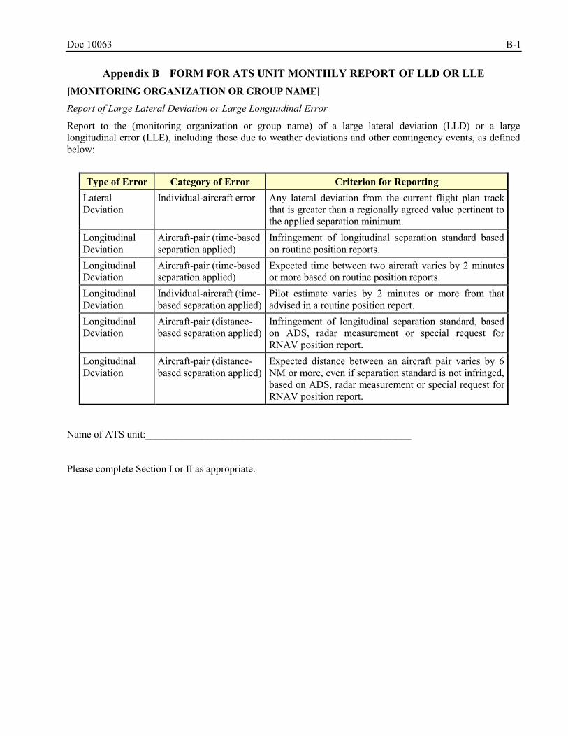
Doc 10063 B-1
Appendix B FORM FOR ATS UNIT MONTHLY REPORT OF LLD OR LLE
[MONITORING ORGANIZATION OR GROUP NAME]
Report of Large Lateral Deviation or Large Longitudinal Error
Report to the (monitoring organization or group name) of a large lateral deviation (LLD) or a large longitudinal error (LLE), including those due to weather deviations and other contingency events, as defined below:
Type of Error Category of Error Criterion for Reporting
Lateral Deviation
Individual-aircraft error Any lateral deviation from the current flight plan track that is greater than a regionally agreed value pertinent to the applied separation minimum.
Longitudinal Deviation
Aircraft-pair (time-based separation applied)
Infringement of longitudinal separation standard based on routine position reports.
Longitudinal Deviation
Aircraft-pair (time-based separation applied)
Expected time between two aircraft varies by 2 minutes or more based on routine position reports.
Longitudinal Deviation
Individual-aircraft (time-based separation applied)
Pilot estimate varies by 2 minutes or more from that advised in a routine position report.
Longitudinal Deviation
Aircraft-pair (distance-based separation applied)
Infringement of longitudinal separation standard, based on ADS, radar measurement or special request for RNAV position report.
Longitudinal Deviation
Aircraft-pair (distance-based separation applied)
Expected distance between an aircraft pair varies by 6 NM or more, even if separation standard is not infringed, based on ADS, radar measurement or special request for RNAV position report.
Name of ATS unit:____________________________________________________
Please complete Section I or II as appropriate.
B-2 Doc 10063
SECTION I:
There were no reports of LLDs or LLEs for the month of __________
SECTION II:
There was/were _____ report(s) of LLD
There was/were _____ report(s) of LLE
Details of the LLDs and LLEs are attached.
(Please use a separate form for each report of lateral deviation or longitudinal error).
SECTION III:
When complete please forward the report(s) to:
En-route monitoring agency or group name
Postal address
Telephone:
Fax:
E-mail:
Doc 10063 B-3
NAVIGATION ERROR INVESTIGATION FORM PART 1 - To be completed by responsible officer in the Service Provider (and aircraft owner/operator if necessary) ATC Unit Observing Error: Date/Time (UTC): Duration of Deviation: Type of Error: (tick one) LATERAL LONGITUDINAL Details of Aircraft First Aircraft
Second Aircraft (when longitudinal deviation observed)
Aircraft Identification: Name of Owner/Operator: Aircraft Type: Departure Point: Destination: Route Segment: Cleared Track: Position where error was observed: (BRG/DIST from fixed point or LAT/LONG)
Extent of deviation – magnitude and direction: (NM for lateral, min/NM for longitudinal)
Flight Level: Approximated Duration of Deviation (minutes)
For All Errors Action taken by ATC: Crew comments when notified of deviation: Other comments:
** (Please Attach ATS Flight Plan)
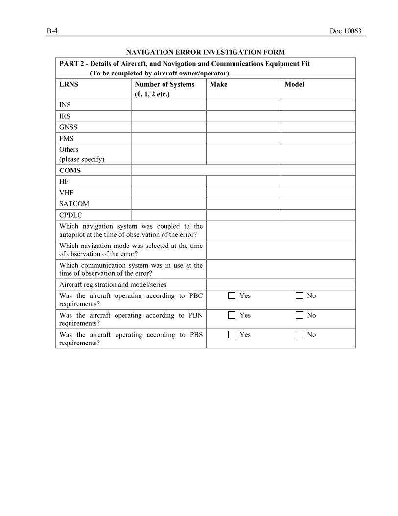
B-4 Doc 10063
NAVIGATION ERROR INVESTIGATION FORM PART 2 - Details of Aircraft, and Navigation and Communications Equipment Fit (To be completed by aircraft owner/operator) LRNS Number of Systems
(0, 1, 2 etc.) Make Model
INS IRS GNSS FMS Others (please specify)
COMS HF VHF SATCOM CPDLC Which navigation system was coupled to the autopilot at the time of observation of the error?
Which navigation mode was selected at the time of observation of the error?
Which communication system was in use at the time of observation of the error?
Aircraft registration and model/series Was the aircraft operating according to PBC requirements?
Yes No
Was the aircraft operating according to PBN requirements?
Yes No
Was the aircraft operating according to PBS requirements?
Yes No
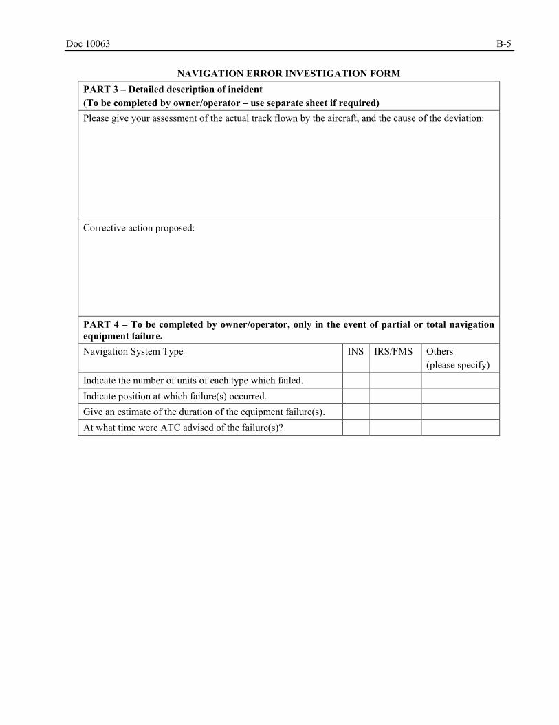
Doc 10063 B-5
NAVIGATION ERROR INVESTIGATION FORM PART 3 – Detailed description of incident (To be completed by owner/operator – use separate sheet if required) Please give your assessment of the actual track flown by the aircraft, and the cause of the deviation: Corrective action proposed: PART 4 – To be completed by owner/operator, only in the event of partial or total navigation equipment failure. Navigation System Type INS IRS/FMS Others
(please specify) Indicate the number of units of each type which failed. Indicate position at which failure(s) occurred. Give an estimate of the duration of the equipment failure(s). At what time were ATC advised of the failure(s)?
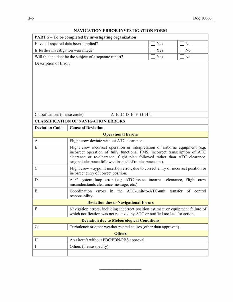
B-6 Doc 10063
NAVIGATION ERROR INVESTIGATION FORM PART 5 – To be completed by investigating organization Have all required data been supplied? Yes No Is further investigation warranted? Yes No Will this incident be the subject of a separate report? Yes No Description of Error: Classification: (please circle) A B C D E F G H I CLASSIFICATION OF NAVIGATION ERRORS Deviation Code Cause of Deviation
Operational Errors A Flight crew deviate without ATC clearance. B Flight crew incorrect operation or interpretation of airborne equipment (e.g.
incorrect operation of fully functional FMS, incorrect transcription of ATC clearance or re-clearance, flight plan followed rather than ATC clearance, original clearance followed instead of re-clearance etc.).
C Flight crew waypoint insertion error, due to correct entry of incorrect position or incorrect entry of correct position.
D ATC system loop error (e.g. ATC issues incorrect clearance, Flight crew misunderstands clearance message, etc.).
E Coordination errors in the ATC-unit-to-ATC-unit transfer of control responsibility.
Deviation due to Navigational Errors F Navigation errors, including incorrect position estimate or equipment failure of
which notification was not received by ATC or notified too late for action. Deviation due to Meteorological Conditions
G Turbulence or other weather related causes (other than approved). Others
H An aircraft without PBC/PBN/PBS approval. I Others (please specify).
______________________
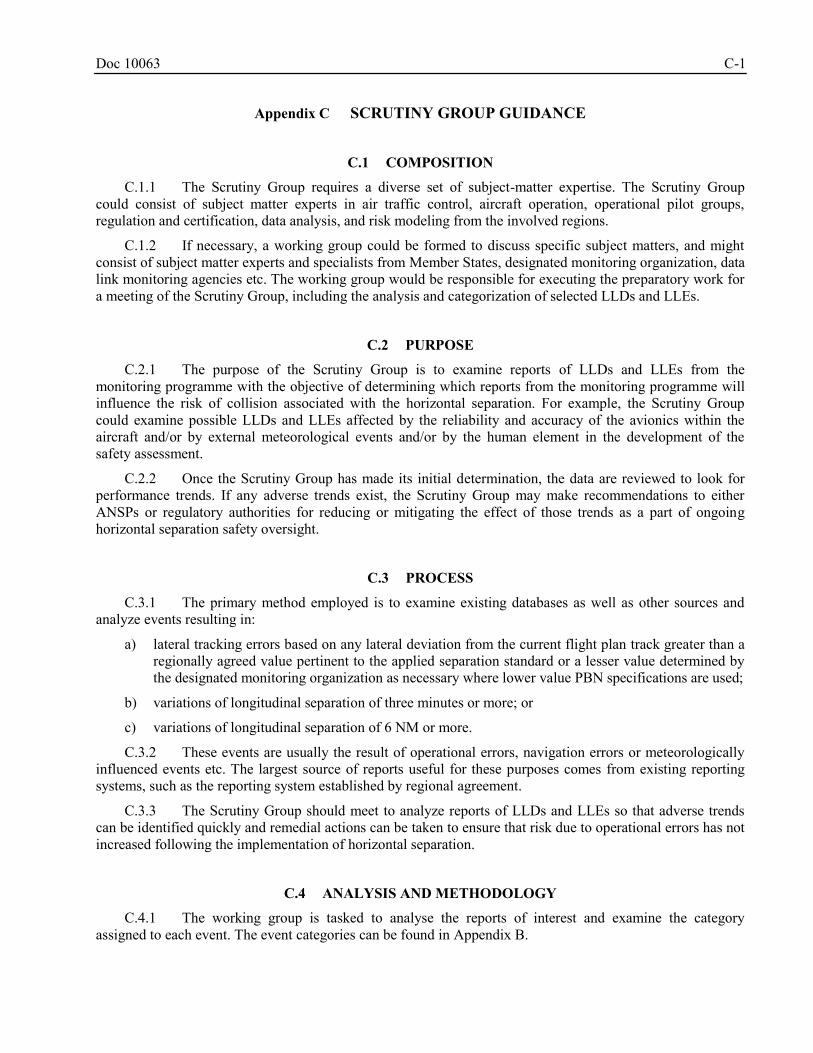
Doc 10063 C-1
Appendix C SCRUTINY GROUP GUIDANCE
COMPOSITION C.1
C.1.1 The Scrutiny Group requires a diverse set of subject-matter expertise. The Scrutiny Group could consist of subject matter experts in air traffic control, aircraft operation, operational pilot groups, regulation and certification, data analysis, and risk modeling from the involved regions.
C.1.2 If necessary, a working group could be formed to discuss specific subject matters, and might consist of subject matter experts and specialists from Member States, designated monitoring organization, data link monitoring agencies etc. The working group would be responsible for executing the preparatory work for a meeting of the Scrutiny Group, including the analysis and categorization of selected LLDs and LLEs.
PURPOSE C.2
C.2.1 The purpose of the Scrutiny Group is to examine reports of LLDs and LLEs from the monitoring programme with the objective of determining which reports from the monitoring programme will influence the risk of collision associated with the horizontal separation. For example, the Scrutiny Group could examine possible LLDs and LLEs affected by the reliability and accuracy of the avionics within the aircraft and/or by external meteorological events and/or by the human element in the development of the safety assessment.
C.2.2 Once the Scrutiny Group has made its initial determination, the data are reviewed to look for performance trends. If any adverse trends exist, the Scrutiny Group may make recommendations to either ANSPs or regulatory authorities for reducing or mitigating the effect of those trends as a part of ongoing horizontal separation safety oversight.
PROCESS C.3
C.3.1 The primary method employed is to examine existing databases as well as other sources and analyze events resulting in:
a) lateral tracking errors based on any lateral deviation from the current flight plan track greater than a regionally agreed value pertinent to the applied separation standard or a lesser value determined by the designated monitoring organization as necessary where lower value PBN specifications are used;
b) variations of longitudinal separation of three minutes or more; or
c) variations of longitudinal separation of 6 NM or more.
C.3.2 These events are usually the result of operational errors, navigation errors or meteorologically influenced events etc. The largest source of reports useful for these purposes comes from existing reporting systems, such as the reporting system established by regional agreement.
C.3.3 The Scrutiny Group should meet to analyze reports of LLDs and LLEs so that adverse trends can be identified quickly and remedial actions can be taken to ensure that risk due to operational errors has not increased following the implementation of horizontal separation.
ANALYSIS AND METHODOLOGY C.4
C.4.1 The working group is tasked to analyse the reports of interest and examine the category assigned to each event. The event categories can be found in Appendix B.

C-2 Doc 10063
C.4.2 The working group relies on its expert judgment and operational experience to analyse these reports. Upon completion of their preliminary analysis, the sub-group will present the results to the Scrutiny Group.
C.4.3 The Scrutiny Group shall examine its working group’s analysis results and take follow-up action as required.
______________________
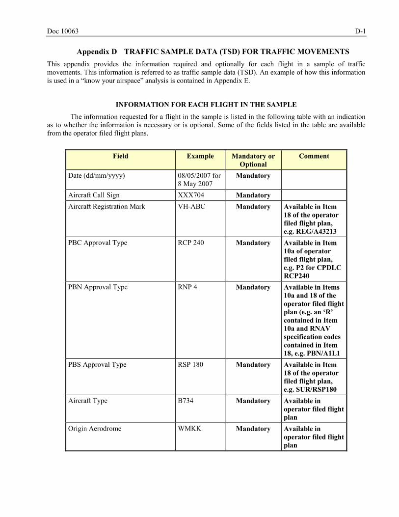
Doc 10063 D-1
Appendix D TRAFFIC SAMPLE DATA (TSD) FOR TRAFFIC MOVEMENTS This appendix provides the information required and optionally for each flight in a sample of traffic movements. This information is referred to as traffic sample data (TSD). An example of how this information is used in a “know your airspace” analysis is contained in Appendix E.
INFORMATION FOR EACH FLIGHT IN THE SAMPLE
The information requested for a flight in the sample is listed in the following table with an indication as to whether the information is necessary or is optional. Some of the fields listed in the table are available from the operator filed flight plans.
Field Example Mandatory or
Optional Comment
Date (dd/mm/yyyy) 08/05/2007 for 8 May 2007
Mandatory
Aircraft Call Sign XXX704 Mandatory Aircraft Registration Mark VH-ABC Mandatory Available in Item
18 of the operator filed flight plan, e.g. REG/A43213
PBC Approval Type RCP 240 Mandatory Available in Item 10a of operator filed flight plan, e.g. P2 for CPDLC RCP240
PBN Approval Type RNP 4 Mandatory Available in Items 10a and 18 of the operator filed flight plan (e.g. an ‘R’ contained in Item 10a and RNAV specification codes contained in Item 18, e.g. PBN/A1L1
PBS Approval Type RSP 180 Mandatory Available in Item 18 of the operator filed flight plan, e.g. SUR/RSP180
Aircraft Type B734 Mandatory Available in operator filed flight plan
Origin Aerodrome WMKK Mandatory Available in operator filed flight plan
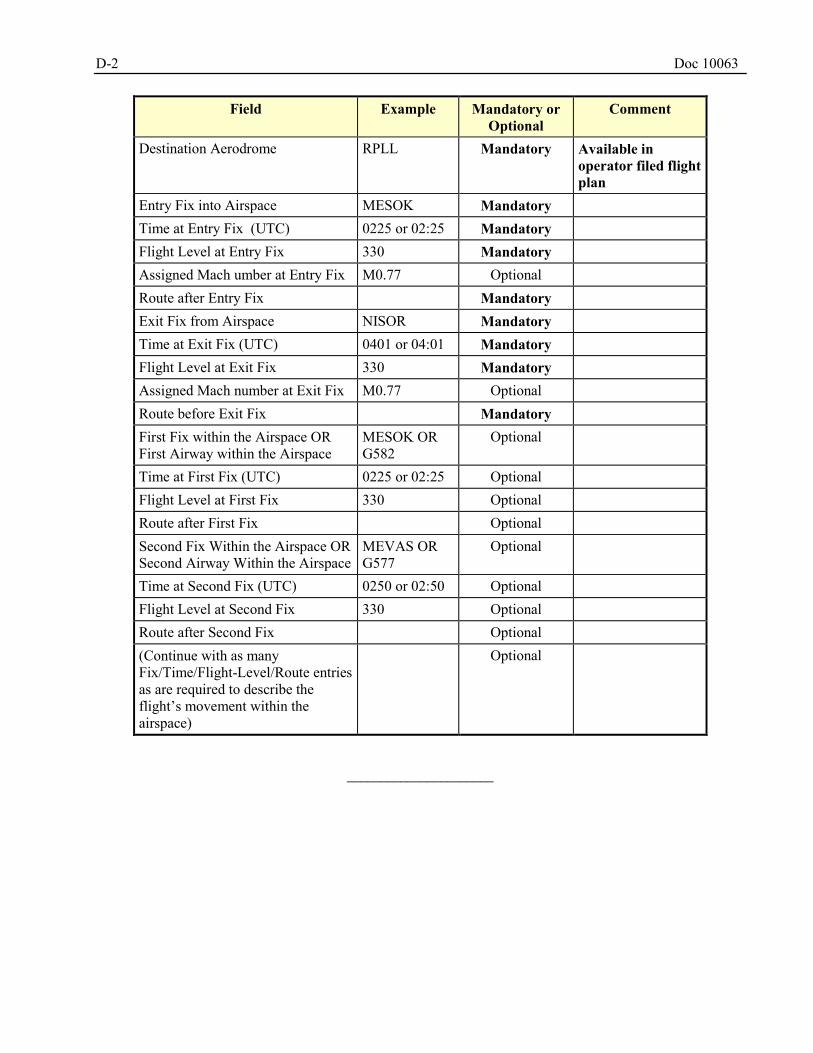
D-2 Doc 10063
Field Example Mandatory or Optional
Comment
Destination Aerodrome RPLL Mandatory Available in operator filed flight plan
Entry Fix into Airspace MESOK Mandatory Time at Entry Fix (UTC) 0225 or 02:25 Mandatory Flight Level at Entry Fix 330 Mandatory Assigned Mach umber at Entry Fix M0.77 Optional Route after Entry Fix Mandatory Exit Fix from Airspace NISOR Mandatory Time at Exit Fix (UTC) 0401 or 04:01 Mandatory Flight Level at Exit Fix 330 Mandatory Assigned Mach number at Exit Fix M0.77 Optional Route before Exit Fix Mandatory First Fix within the Airspace OR First Airway within the Airspace
MESOK OR G582
Optional
Time at First Fix (UTC) 0225 or 02:25 Optional Flight Level at First Fix 330 Optional Route after First Fix Optional Second Fix Within the Airspace OR Second Airway Within the Airspace
MEVAS OR G577
Optional
Time at Second Fix (UTC) 0250 or 02:50 Optional Flight Level at Second Fix 330 Optional Route after Second Fix Optional (Continue with as many Fix/Time/Flight-Level/Route entries as are required to describe the flight’s movement within the airspace)
Optional
______________________
Doc 10063 E-1
Appendix E EXAMPLE “KNOW YOUR AIRSPACE” ANALYSIS
EXAMINATION OF OPERATIONS CONDUCTED ON SOUTH CHINA SEA - RNAV
ROUTES L642 AND M771
INTRODUCTION E.1
E.1.1 This appendix is an example of a “Know Your Airspace” analysis. It shows how the characteristics of ATS routes L642 and M771 airspace analysis, derived from the traffic movement data collected during December 2007 and other sources, could support the safety assessment on the implementation of the horizontal separation minima.
BACKGROUND E.2
E.2.1 As the result of APANPIRG agreement, traffic movement information is collected each December from all Asia/Pacific Region flight information regions (FIRs) within which the Reduced Vertical Separation Minimum (RVSM) is applied. The traffic movement sample is termed the Traffic Sample Data (TSD). The TSD contains information for each flight operating in RVSM airspace during the month:
E.2.2 These data contribute to the conduct of an annual assessment of the safety of continued RVSM use. With proper treatment, these data are also useful to support assessment of the safety of lateral and longitudinal separation minima. The information required and optionally for each flight in a sample of traffic movements is contained in Appendix D.
E.2.3 Four FIRs – Ho Chi Minh, Hong Kong, Sanya and Singapore – have air traffic control responsibility for L642 and M771. Records of all flights operating on L642 and M771 from each of the four TSDs were merged through a software process to avoid duplicate counting of flights. The resulting combined TSD was compared to the TSD from each FIR in order to check for flights missing from individual TSDs but reported in others, and for agreement of times at fixes common to two TSDs. These and other consistency checks led to the conclusion that the quality of data-entry in each of the TSD samples was very high, and that, as a consequence, the combined December 2007 TSD provided a highly reliable basis for gaining insight into the airspace characteristics of flight operations on L642 and M771.
E.2.4 After processing and merging, a total of 5 743 flight operations were observed on L642 and M771 during December 2007.
CHARACTERISTICS OF L642 AND M771 E.3
E.3.1 Operator profile
E.3.1.1 Flights operating on L642 and M771 in the combined December 2007 TSD were examined to identify and quantify several important characteristics of airspace use. Principal among these are the profile of operators using the routes, the aircraft types observed on the routes, the origin-destination aerodrome pairs for operations, flight level use on the routes and the operator/aircraft-type pairs seen to have used L642 or M771.
E.3.1.2 Each traffic movement was examined to determine the operator conducting the flight. A total of sixty-one unique three-letter ICAO operator designators were observed in the merged TSD. Table E-1 presents the top twenty-five of these operator-designator counts, which account for nearly 97 per cent of the operations. As will be noted, the top four operators account for nearly half of the operations, while the top ten account for about three operations in four.
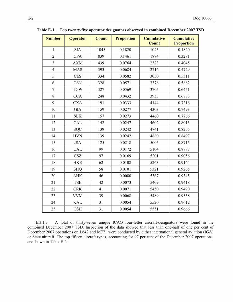
E-2 Doc 10063
Table E-1. Top twenty-five operator designators observed in combined December 2007 TSD
Number Operator Count Proportion Cumulative Count
Cumulative Proportion
1 SIA 1045 0.1820 1045 0.1820 2 CPA 839 0.1461 1884 0.3281 3 AXM 439 0.0764 2323 0.4045 4 MAS 393 0.0684 2716 0.4729 5 CES 334 0.0582 3050 0.5311 6 CSN 328 0.0571 3378 0.5882 7 TGW 327 0.0569 3705 0.6451 8 CCA 248 0.0432 3953 0.6883 9 CXA 191 0.0333 4144 0.7216 10 GIA 159 0.0277 4303 0.7493 11 SLK 157 0.0273 4460 0.7766 12 CAL 142 0.0247 4602 0.8013 13 SQC 139 0.0242 4741 0.8255 14 HVN 139 0.0242 4880 0.8497 15 JSA 125 0.0218 5005 0.8715 16 UAL 99 0.0172 5104 0.8887 17 CSZ 97 0.0169 5201 0.9056 18 HKE 62 0.0108 5263 0.9164 19 SHQ 58 0.0101 5321 0.9265 20 AHK 46 0.0080 5367 0.9345 21 TSE 42 0.0073 5409 0.9418 22 CRK 41 0.0071 5450 0.9490 23 VVM 39 0.0068 5489 0.9558 24 KAL 31 0.0054 5520 0.9612 25 CSH 31 0.0054 5551 0.9666
E.3.1.3 A total of thirty-seven unique ICAO four-letter aircraft-designators were found in the combined December 2007 TSD. Inspection of the data showed that less than one-half of one per cent of December 2007 operations on L642 and M771 were conducted by either international general aviation (IGA) or State aircraft. The top fifteen aircraft types, accounting for 97 per cent of the December 2007 operations, are shown in Table E-2.
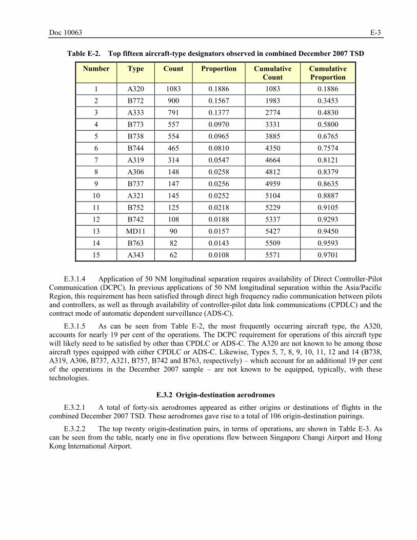
Doc 10063 E-3
Table E-2. Top fifteen aircraft-type designators observed in combined December 2007 TSD
Number Type Count Proportion Cumulative Count
Cumulative Proportion
1 A320 1083 0.1886 1083 0.1886 2 B772 900 0.1567 1983 0.3453 3 A333 791 0.1377 2774 0.4830 4 B773 557 0.0970 3331 0.5800 5 B738 554 0.0965 3885 0.6765 6 B744 465 0.0810 4350 0.7574 7 A319 314 0.0547 4664 0.8121 8 A306 148 0.0258 4812 0.8379 9 B737 147 0.0256 4959 0.8635 10 A321 145 0.0252 5104 0.8887 11 B752 125 0.0218 5229 0.9105 12 B742 108 0.0188 5337 0.9293 13 MD11 90 0.0157 5427 0.9450 14 B763 82 0.0143 5509 0.9593 15 A343 62 0.0108 5571 0.9701
E.3.1.4 Application of 50 NM longitudinal separation requires availability of Direct Controller-Pilot Communication (DCPC). In previous applications of 50 NM longitudinal separation within the Asia/Pacific Region, this requirement has been satisfied through direct high frequency radio communication between pilots and controllers, as well as through availability of controller-pilot data link communications (CPDLC) and the contract mode of automatic dependent surveillance (ADS-C).
E.3.1.5 As can be seen from Table E-2, the most frequently occurring aircraft type, the A320, accounts for nearly 19 per cent of the operations. The DCPC requirement for operations of this aircraft type will likely need to be satisfied by other than CPDLC or ADS-C. The A320 are not known to be among those aircraft types equipped with either CPDLC or ADS-C. Likewise, Types 5, 7, 8, 9, 10, 11, 12 and 14 (B738, A319, A306, B737, A321, B757, B742 and B763, respectively) – which account for an additional 19 per cent of the operations in the December 2007 sample – are not known to be equipped, typically, with these technologies.
E.3.2 Origin-destination aerodromes
E.3.2.1 A total of forty-six aerodromes appeared as either origins or destinations of flights in the combined December 2007 TSD. These aerodromes gave rise to a total of 106 origin-destination pairings.
E.3.2.2 The top twenty origin-destination pairs, in terms of operations, are shown in Table E-3. As can be seen from the table, nearly one in five operations flew between Singapore Changi Airport and Hong Kong International Airport.
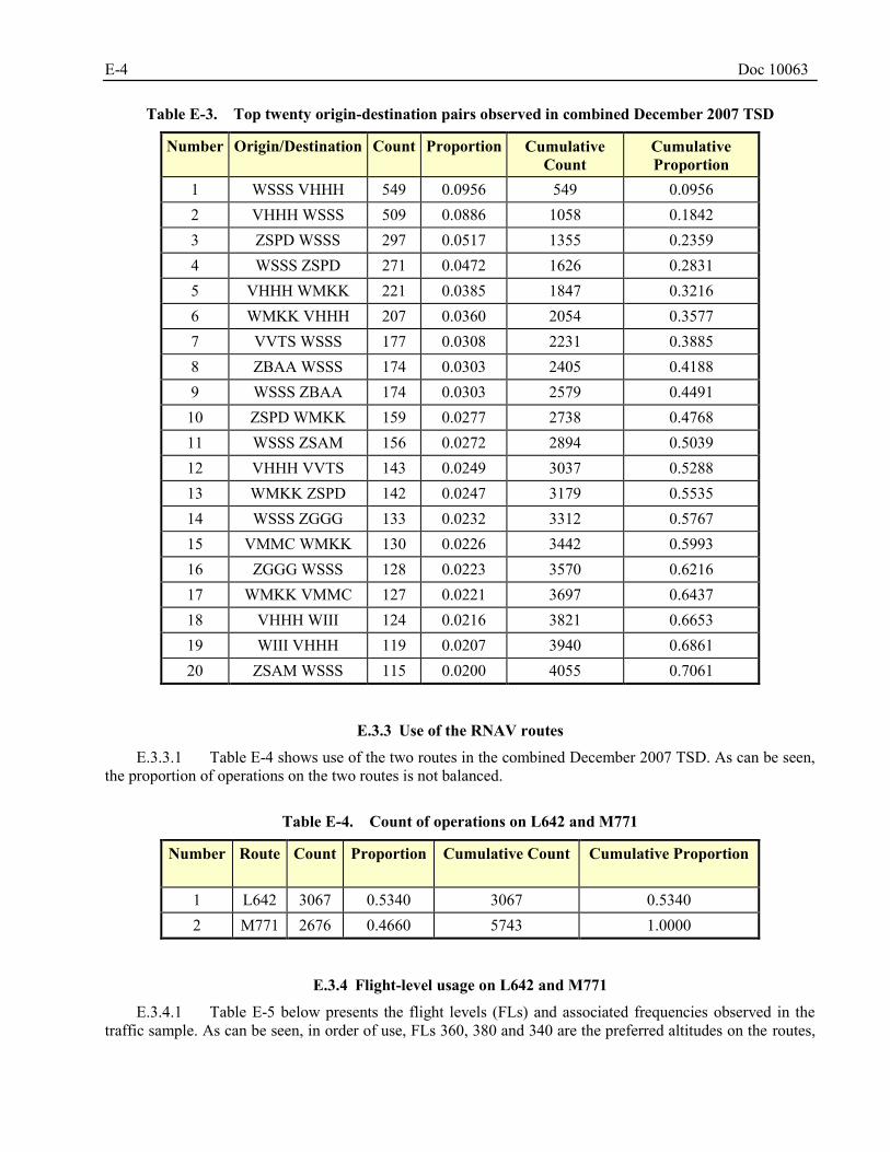
E-4 Doc 10063
Table E-3. Top twenty origin-destination pairs observed in combined December 2007 TSD
Number Origin/Destination Count Proportion Cumulative Count
Cumulative Proportion
1 WSSS VHHH 549 0.0956 549 0.0956 2 VHHH WSSS 509 0.0886 1058 0.1842 3 ZSPD WSSS 297 0.0517 1355 0.2359 4 WSSS ZSPD 271 0.0472 1626 0.2831 5 VHHH WMKK 221 0.0385 1847 0.3216 6 WMKK VHHH 207 0.0360 2054 0.3577 7 VVTS WSSS 177 0.0308 2231 0.3885 8 ZBAA WSSS 174 0.0303 2405 0.4188 9 WSSS ZBAA 174 0.0303 2579 0.4491 10 ZSPD WMKK 159 0.0277 2738 0.4768 11 WSSS ZSAM 156 0.0272 2894 0.5039 12 VHHH VVTS 143 0.0249 3037 0.5288 13 WMKK ZSPD 142 0.0247 3179 0.5535 14 WSSS ZGGG 133 0.0232 3312 0.5767 15 VMMC WMKK 130 0.0226 3442 0.5993 16 ZGGG WSSS 128 0.0223 3570 0.6216 17 WMKK VMMC 127 0.0221 3697 0.6437 18 VHHH WIII 124 0.0216 3821 0.6653 19 WIII VHHH 119 0.0207 3940 0.6861 20 ZSAM WSSS 115 0.0200 4055 0.7061
E.3.3 Use of the RNAV routes
E.3.3.1 Table E-4 shows use of the two routes in the combined December 2007 TSD. As can be seen, the proportion of operations on the two routes is not balanced.
Table E-4. Count of operations on L642 and M771
Number Route Count Proportion
Cumulative Count Cumulative Proportion
1 L642 3067 0.5340 3067 0.5340 2 M771 2676 0.4660 5743 1.0000
E.3.4 Flight-level usage on L642 and M771
E.3.4.1 Table E-5 below presents the flight levels (FLs) and associated frequencies observed in the traffic sample. As can be seen, in order of use, FLs 360, 380 and 340 are the preferred altitudes on the routes,
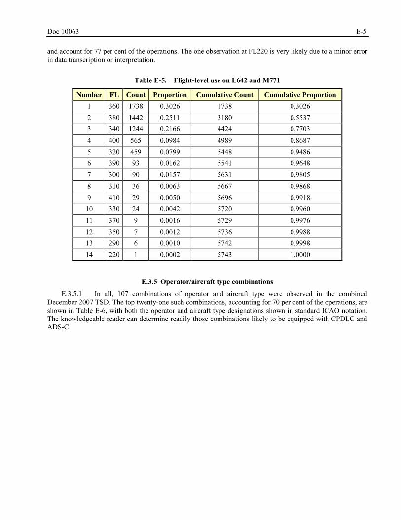
Doc 10063 E-5
and account for 77 per cent of the operations. The one observation at FL220 is very likely due to a minor error in data transcription or interpretation.
Table E-5. Flight-level use on L642 and M771
Number FL Count Proportion Cumulative Count Cumulative Proportion 1 360 1738 0.3026 1738 0.3026 2 380 1442 0.2511 3180 0.5537 3 340 1244 0.2166 4424 0.7703 4 400 565 0.0984 4989 0.8687 5 320 459 0.0799 5448 0.9486 6 390 93 0.0162 5541 0.9648 7 300 90 0.0157 5631 0.9805 8 310 36 0.0063 5667 0.9868 9 410 29 0.0050 5696 0.9918 10 330 24 0.0042 5720 0.9960 11 370 9 0.0016 5729 0.9976 12 350 7 0.0012 5736 0.9988 13 290 6 0.0010 5742 0.9998 14 220 1 0.0002 5743 1.0000
E.3.5 Operator/aircraft type combinations
E.3.5.1 In all, 107 combinations of operator and aircraft type were observed in the combined December 2007 TSD. The top twenty-one such combinations, accounting for 70 per cent of the operations, are shown in Table E-6, with both the operator and aircraft type designations shown in standard ICAO notation. The knowledgeable reader can determine readily those combinations likely to be equipped with CPDLC and ADS-C.
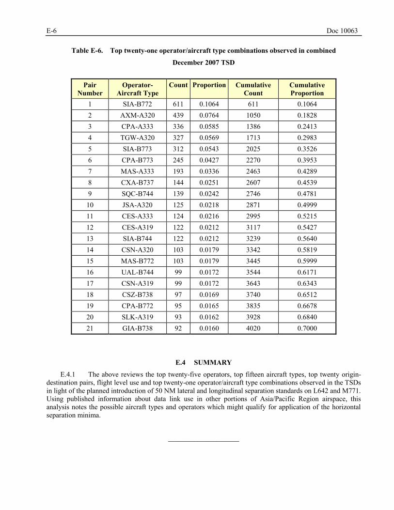
E-6 Doc 10063
Table E-6. Top twenty-one operator/aircraft type combinations observed in combined
December 2007 TSD
Pair
Number Operator-
Aircraft Type Count Proportion Cumulative
Count Cumulative Proportion
1 SIA-B772 611 0.1064 611 0.1064 2 AXM-A320 439 0.0764 1050 0.1828 3 CPA-A333 336 0.0585 1386 0.2413 4 TGW-A320 327 0.0569 1713 0.2983 5 SIA-B773 312 0.0543 2025 0.3526 6 CPA-B773 245 0.0427 2270 0.3953 7 MAS-A333 193 0.0336 2463 0.4289 8 CXA-B737 144 0.0251 2607 0.4539 9 SQC-B744 139 0.0242 2746 0.4781
10 JSA-A320 125 0.0218 2871 0.4999 11 CES-A333 124 0.0216 2995 0.5215 12 CES-A319 122 0.0212 3117 0.5427 13 SIA-B744 122 0.0212 3239 0.5640 14 CSN-A320 103 0.0179 3342 0.5819 15 MAS-B772 103 0.0179 3445 0.5999 16 UAL-B744 99 0.0172 3544 0.6171 17 CSN-A319 99 0.0172 3643 0.6343 18 CSZ-B738 97 0.0169 3740 0.6512 19 CPA-B772 95 0.0165 3835 0.6678 20 SLK-A319 93 0.0162 3928 0.6840 21 GIA-B738 92 0.0160 4020 0.7000
SUMMARY E.4
E.4.1 The above reviews the top twenty-five operators, top fifteen aircraft types, top twenty origin-destination pairs, flight level use and top twenty-one operator/aircraft type combinations observed in the TSDs in light of the planned introduction of 50 NM lateral and longitudinal separation standards on L642 and M771. Using published information about data link use in other portions of Asia/Pacific Region airspace, this analysis notes the possible aircraft types and operators which might qualify for application of the horizontal separation minima.
______________________
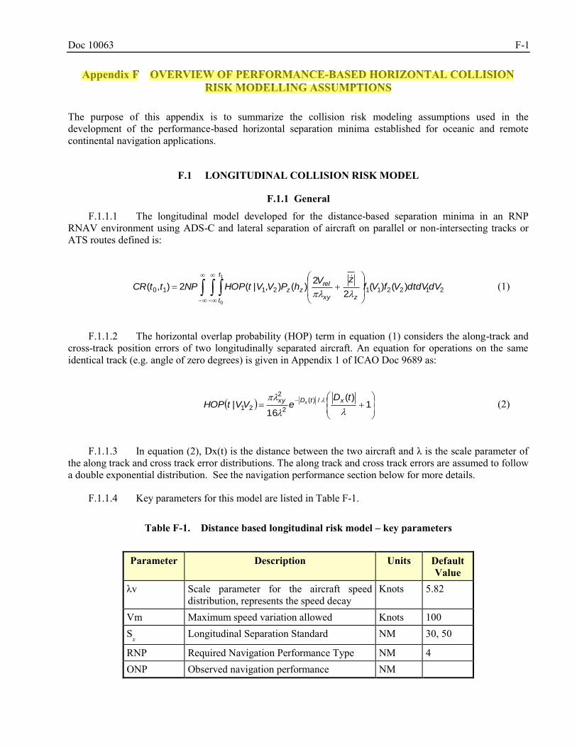
Doc 10063 F-1
Appendix F OVERVIEW OF PERFORMANCE-BASED HORIZONTAL COLLISION
RISK MODELLING ASSUMPTIONS
The purpose of this appendix is to summarize the collision risk modeling assumptions used in the development of the performance-based horizontal separation minima established for oceanic and remote continental navigation applications.
LONGITUDINAL COLLISION RISK MODEL F.1
F.1.1 General
F.1.1.1 The longitudinal model developed for the distance-based separation minima in an RNP RNAV environment using ADS-C and lateral separation of aircraft on parallel or non-intersecting tracks or ATS routes defined is:
2122112110 )()(2
2)(),|(2),(
1
0
dVdtdVVfVfzV
hPVVtHOPNPttCR
t
t zxy
relzz
(1)
F.1.1.2 The horizontal overlap probability (HOP) term in equation (1) considers the along-track and cross-track position errors of two longitudinally separated aircraft. An equation for operations on the same identical track (e.g. angle of zero degrees) is given in Appendix 1 of ICAO Doc 9689 as:
1
)(
16|
/)(
2
2
21
tDeVVtHOP
xtDxy x (2)
F.1.1.3 In equation (2), Dx(t) is the distance between the two aircraft and λ is the scale parameter of the along track and cross track error distributions. The along track and cross track errors are assumed to follow a double exponential distribution. See the navigation performance section below for more details.
F.1.1.4 Key parameters for this model are listed in Table F-1.
Table F-1. Distance based longitudinal risk model – key parameters
Parameter Description Units Default
Value λv Scale parameter for the aircraft speed
distribution, represents the speed decay Knots 5.82
Vm Maximum speed variation allowed Knots 100 Sx Longitudinal Separation Standard NM 30, 50
RNP Required Navigation Performance Type NM 4 ONP Observed navigation performance NM
Stephanie.Beritsky
Highlight
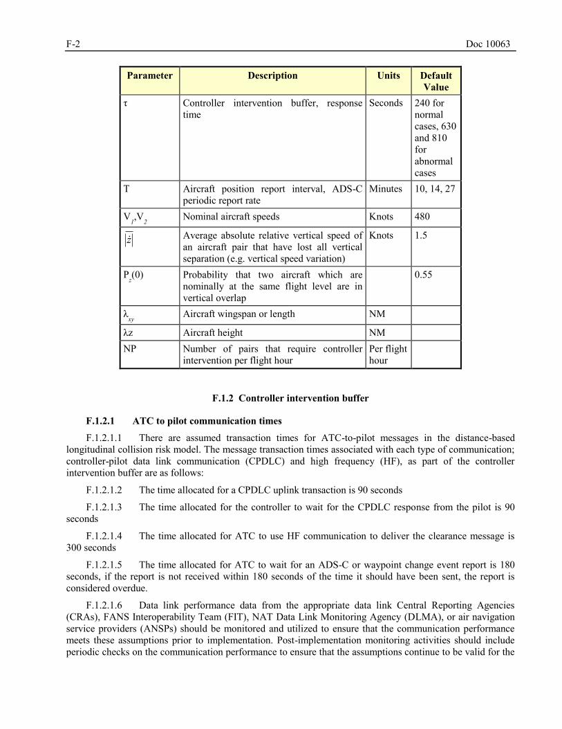
F-2 Doc 10063
Parameter Description Units Default Value
τ Controller intervention buffer, response time
Seconds 240 for normal cases, 630 and 810 for abnormal cases
T Aircraft position report interval, ADS-C periodic report rate
Minutes 10, 14, 27
V1,V2 Nominal aircraft speeds Knots 480
z Average absolute relative vertical speed of an aircraft pair that have lost all vertical separation (e.g. vertical speed variation)
Knots 1.5
Pz(0) Probability that two aircraft which are
nominally at the same flight level are in vertical overlap
0.55
λxy
Aircraft wingspan or length NM
λz Aircraft height NM NP Number of pairs that require controller
intervention per flight hour Per flight hour
F.1.2 Controller intervention buffer
F.1.2.1 ATC to pilot communication times
F.1.2.1.1 There are assumed transaction times for ATC-to-pilot messages in the distance-based longitudinal collision risk model. The message transaction times associated with each type of communication; controller-pilot data link communication (CPDLC) and high frequency (HF), as part of the controller intervention buffer are as follows:
F.1.2.1.2 The time allocated for a CPDLC uplink transaction is 90 seconds
F.1.2.1.3 The time allocated for the controller to wait for the CPDLC response from the pilot is 90 seconds
F.1.2.1.4 The time allocated for ATC to use HF communication to deliver the clearance message is 300 seconds
F.1.2.1.5 The time allocated for ATC to wait for an ADS-C or waypoint change event report is 180 seconds, if the report is not received within 180 seconds of the time it should have been sent, the report is considered overdue.
F.1.2.1.6 Data link performance data from the appropriate data link Central Reporting Agencies (CRAs), FANS Interoperability Team (FIT), NAT Data Link Monitoring Agency (DLMA), or air navigation service providers (ANSPs) should be monitored and utilized to ensure that the communication performance meets these assumptions prior to implementation. Post-implementation monitoring activities should include periodic checks on the communication performance to ensure that the assumptions continue to be valid for the
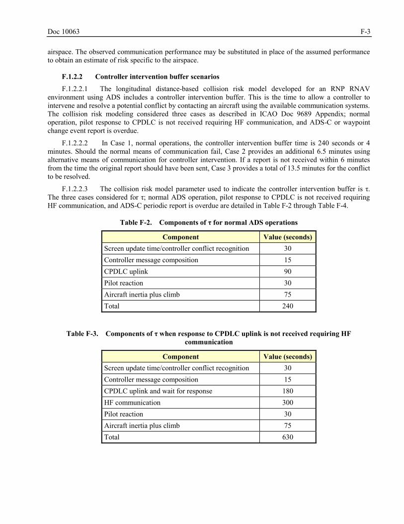
Doc 10063 F-3
airspace. The observed communication performance may be substituted in place of the assumed performance to obtain an estimate of risk specific to the airspace.
F.1.2.2 Controller intervention buffer scenarios
F.1.2.2.1 The longitudinal distance-based collision risk model developed for an RNP RNAV environment using ADS includes a controller intervention buffer. This is the time to allow a controller to intervene and resolve a potential conflict by contacting an aircraft using the available communication systems. The collision risk modeling considered three cases as described in ICAO Doc 9689 Appendix; normal operation, pilot response to CPDLC is not received requiring HF communication, and ADS-C or waypoint change event report is overdue.
F.1.2.2.2 In Case 1, normal operations, the controller intervention buffer time is 240 seconds or 4 minutes. Should the normal means of communication fail, Case 2 provides an additional 6.5 minutes using alternative means of communication for controller intervention. If a report is not received within 6 minutes from the time the original report should have been sent, Case 3 provides a total of 13.5 minutes for the conflict to be resolved.
F.1.2.2.3 The collision risk model parameter used to indicate the controller intervention buffer is τ. The three cases considered for τ; normal ADS operation, pilot response to CPDLC is not received requiring HF communication, and ADS-C periodic report is overdue are detailed in Table F-2 through Table F-4.
Table F-2. Components of τ for normal ADS operations
Component Value (seconds) Screen update time/controller conflict recognition 30 Controller message composition 15 CPDLC uplink 90 Pilot reaction 30 Aircraft inertia plus climb 75 Total 240
Table F-3. Components of τ when response to CPDLC uplink is not received requiring HF
communication
Component Value (seconds) Screen update time/controller conflict recognition 30 Controller message composition 15 CPDLC uplink and wait for response 180 HF communication 300 Pilot reaction 30 Aircraft inertia plus climb 75 Total 630
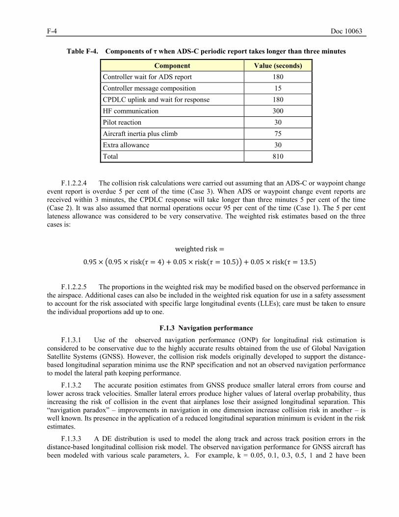
F-4 Doc 10063
Table F-4. Components of τ when ADS-C periodic report takes longer than three minutes
Component Value (seconds) Controller wait for ADS report 180 Controller message composition 15 CPDLC uplink and wait for response 180 HF communication 300 Pilot reaction 30 Aircraft inertia plus climb 75 Extra allowance 30 Total 810
F.1.2.2.4 The collision risk calculations were carried out assuming that an ADS-C or waypoint change event report is overdue 5 per cent of the time (Case 3). When ADS or waypoint change event reports are received within 3 minutes, the CPDLC response will take longer than three minutes 5 per cent of the time (Case 2). It was also assumed that normal operations occur 95 per cent of the time (Case 1). The 5 per cent lateness allowance was considered to be very conservative. The weighted risk estimates based on the three cases is:
weighted risk =
0.95 × (0.95 × risk(𝜏 = 4) + 0.05 × risk(𝜏 = 10.5)) + 0.05 × risk(𝜏 = 13.5)
F.1.2.2.5 The proportions in the weighted risk may be modified based on the observed performance in the airspace. Additional cases can also be included in the weighted risk equation for use in a safety assessment to account for the risk associated with specific large longitudinal events (LLEs); care must be taken to ensure the individual proportions add up to one.
F.1.3 Navigation performance
F.1.3.1 Use of the observed navigation performance (ONP) for longitudinal risk estimation is considered to be conservative due to the highly accurate results obtained from the use of Global Navigation Satellite Systems (GNSS). However, the collision risk models originally developed to support the distance-based longitudinal separation minima use the RNP specification and not an observed navigation performance to model the lateral path keeping performance.
F.1.3.2 The accurate position estimates from GNSS produce smaller lateral errors from course and lower across track velocities. Smaller lateral errors produce higher values of lateral overlap probability, thus increasing the risk of collision in the event that airplanes lose their assigned longitudinal separation. This “navigation paradox” – improvements in navigation in one dimension increase collision risk in another – is well known. Its presence in the application of a reduced longitudinal separation minimum is evident in the risk estimates.
F.1.3.3 A DE distribution is used to model the along track and across track position errors in the distance-based longitudinal collision risk model. The observed navigation performance for GNSS aircraft has been modeled with various scale parameters, λ. For example, k = 0.05, 0.1, 0.3, 0.5, 1 and 2 have been
Doc 10063 F-5
employed to compute λ = −𝑘
ln (0.05) . The parameter λ is chosen to satisfy the requirement∫ 𝑓(𝑦)𝑑𝑦 =
∞
−∞
0.95, which states that these RNP aircraft are expected to have position errors less than k NM in magnitude during 95 per cent of their flight time. The value for k is chosen to be lower than the RNP specification due to the very accurate GNSS positions.
F.1.4 Variation in aircraft speed
F.1.4.1 The longitudinal distance-based collision risk model developed for an RNP RNAV environment using ADS accounts for variation in aircraft speed during a time period. This time period is the time between consecutive position reports and the time allotted for the controller intervention buffer.
F.1.4.2 The speed variation follows a DE distribution with scale parameter λv=5.82 knots. The assumed average aircraft ground speed of 480 knots is used as the location parameter, Vo. The DE distribution is truncated at 100 knots on either side of the location parameter, 480 knots, and then normalized to equal one.
𝑓𝐷𝐸(𝑉) =1
2𝜆𝑣𝑒
−|𝑉−𝑉𝑜|
𝜆𝑣 for − 100 < 𝑉 < 100
F.1.4.3 The empirical speed variations can be observed in the airspace and used to modify the scale parameter, location parameter or truncation limits. Care must be taken to ensure that the resulting speed variation distribution is suitable for all the appropriate time periods. The time period is equal to the aircraft reporting period plus the allotted time for the controller intervention buffer. It is possible to have multiple aircraft speed variation distributions for use in the collision risk modeling as aircraft speed can be expected to vary greatly over long time periods.
LATERAL COLLISION RISK MODEL F.2
F.2.1 General
F.2.1.1 The form of the lateral collision risk model applicable to assessing the risk, Nay, of a 30 NM lateral separation standard from Appendix 15 of ICAO Doc 9689 is:
zy
y
xy
zy
y
xy
x
xzyyay
zSyVoppE
zSyxsameE
SPSPN
22
)()(
22
)(
2)()0()(
(3)
F.2.1.2 Where the individual parameters of the lateral collision risk model and their definitions are given in Table F-5.
Table F-5. Lateral collision risk model – key parameters
Parameter Description Units Default Value Sy Lateral Separation Standard NM 30, 50
RNP Required Navigation Performance Type NM 4, 10
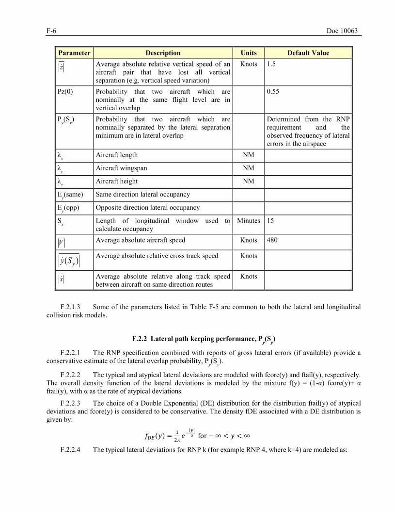
F-6 Doc 10063
Parameter Description Units Default Value
z Average absolute relative vertical speed of an aircraft pair that have lost all vertical separation (e.g. vertical speed variation)
Knots 1.5
Pz(0) Probability that two aircraft which are nominally at the same flight level are in vertical overlap
0.55
Py(Sy) Probability that two aircraft which are
nominally separated by the lateral separation minimum are in lateral overlap
Determined from the RNP requirement and the observed frequency of lateral errors in the airspace
λx Aircraft length NM
λy Aircraft wingspan NM
λz Aircraft height NM
Ey(same) Same direction lateral occupancy
Ey(opp) Opposite direction lateral occupancy
Sx Length of longitudinal window used to
calculate occupancy Minutes 15
Average absolute aircraft speed Knots 480
)( ySy
Average absolute relative cross track speed Knots
x Average absolute relative along track speed between aircraft on same direction routes
Knots
F.2.1.3 Some of the parameters listed in Table F-5 are common to both the lateral and longitudinal collision risk models.
F.2.2 Lateral path keeping performance, Py(Sy)
F.2.2.1 The RNP specification combined with reports of gross lateral errors (if available) provide a conservative estimate of the lateral overlap probability, P
y(Sy).
F.2.2.2 The typical and atypical lateral deviations are modeled with fcore(y) and ftail(y), respectively. The overall density function of the lateral deviations is modeled by the mixture f(y) = (1-α) fcore(y)+ α ftail(y), with α as the rate of atypical deviations.
F.2.2.3 The choice of a Double Exponential (DE) distribution for the distribution ftail(y) of atypical deviations and fcore(y) is considered to be conservative. The density fDE associated with a DE distribution is given by:
𝑓𝐷𝐸(𝑦) =1
2𝜆𝑒−
|𝑦|
𝜆 for − ∞ < 𝑦 < ∞
F.2.2.4 The typical lateral deviations for RNP k (for example RNP 4, where k=4) are modeled as:
V
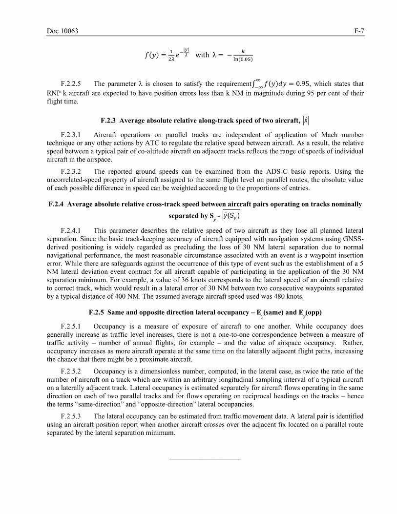
Doc 10063 F-7
𝑓(𝑦) =1
2𝜆𝑒−
|𝑦|
𝜆 with λ = −𝑘
ln (0.05)
F.2.2.5 The parameter λ is chosen to satisfy the requirement∫ 𝑓(𝑦)𝑑𝑦 = 0.95∞
−∞, which states that
RNP k aircraft are expected to have position errors less than k NM in magnitude during 95 per cent of their flight time.
F.2.3 Average absolute relative along-track speed of two aircraft, x
F.2.3.1 Aircraft operations on parallel tracks are independent of application of Mach number technique or any other actions by ATC to regulate the relative speed between aircraft. As a result, the relative speed between a typical pair of co-altitude aircraft on adjacent tracks reflects the range of speeds of individual aircraft in the airspace.
F.2.3.2 The reported ground speeds can be examined from the ADS-C basic reports. Using the uncorrelated-speed property of aircraft assigned to the same flight level on parallel routes, the absolute value of each possible difference in speed can be weighted according to the proportions of entries.
F.2.4 Average absolute relative cross-track speed between aircraft pairs operating on tracks nominally
separated by Sy - )( ySy
F.2.4.1 This parameter describes the relative speed of two aircraft as they lose all planned lateral separation. Since the basic track-keeping accuracy of aircraft equipped with navigation systems using GNSS-derived positioning is widely regarded as precluding the loss of 30 NM lateral separation due to normal navigational performance, the most reasonable circumstance associated with an event is a waypoint insertion error. While there are safeguards against the occurrence of this type of event such as the establishment of a 5 NM lateral deviation event contract for all aircraft capable of participating in the application of the 30 NM separation minimum. For example, a value of 36 knots corresponds to the lateral speed of an aircraft relative to correct track, which would result in a lateral error of 30 NM between two consecutive waypoints separated by a typical distance of 400 NM. The assumed average aircraft speed used was 480 knots.
F.2.5 Same and opposite direction lateral occupancy – Ey(same) and E
y(opp)
F.2.5.1 Occupancy is a measure of exposure of aircraft to one another. While occupancy does generally increase as traffic level increases, there is not a one-to-one correspondence between a measure of traffic activity – number of annual flights, for example – and the value of airspace occupancy. Rather, occupancy increases as more aircraft operate at the same time on the laterally adjacent flight paths, increasing the chance that there might be a proximate aircraft.
F.2.5.2 Occupancy is a dimensionless number, computed, in the lateral case, as twice the ratio of the number of aircraft on a track which are within an arbitrary longitudinal sampling interval of a typical aircraft on a laterally adjacent track. Lateral occupancy is estimated separately for aircraft flows operating in the same direction on each of two parallel tracks and for flows operating on reciprocal headings on the tracks – hence the terms “same-direction” and “opposite-direction” lateral occupancies.
F.2.5.3 The lateral occupancy can be estimated from traffic movement data. A lateral pair is identified using an aircraft position report when another aircraft crosses over the adjacent fix located on a parallel route separated by the lateral separation minimum.
______________________

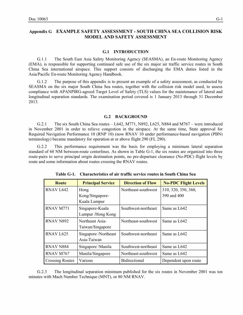
Doc 10063 G-1
Appendix G EXAMPLE SAFETY ASSESSMENT - SOUTH CHINA SEA COLLISION RISK MODEL AND SAFETY ASSESSMENT
G.1 INTRODUCTION
G.1.1 The South East Asia Safety Monitoring Agency (SEASMA), an En-route Monitoring Agency (EMA), is responsible for supporting continued safe use of the six major air traffic service routes in South China Sea international airspace. This support consists of discharging the EMA duties listed in the Asia/Pacific En-route Monitoring Agency Handbook.
G.1.2 The purpose of this appendix is to present an example of a safety assessment, as conducted by SEASMA on the six major South China Sea routes, together with the collision risk model used, to assess compliance with APANPIRG-agreed Target Level of Safety (TLS) values for the maintenance of lateral and longitudinal separation standards. The examination period covered is 1 January 2013 through 31 December 2013.
G.2 BACKGROUND
G.2.1 The six South China Sea routes – L642, M771, N892, L625, N884 and M767 – were introduced in November 2001 in order to relieve congestion in the airspace. At the same time, State approval for Required Navigation Performance 10 (RNP 10) (now RNAV 10 under performance-based navigation (PBN) terminology) became mandatory for operation at or above flight 290 (FL 290).
G.2.2 This performance requirement was the basis for employing a minimum lateral separation standard of 60 NM between-route centerlines. As shown in Table G-1, the six routes are organized into three route-pairs to serve principal origin destination points, no pre-departure clearance (No-PDC) flight levels by route and some information about routes crossing the RNAV routes.
Table G-1. Characteristics of air traffic service routes in South China Sea
Route Principal Service Direction of Flow No-PDC Flight Levels RNAV L642 Hong
Kong/Singapore- Kuala Lumpur
Northeast-southwest 310, 320, 350, 360, 390 and 400
RNAV M771 Singapore-Kuala Lumpur /Hong Kong
Southwest-northeast Same as L642
RNAV N892 Northeast Asia- Taiwan/Singapore
Northeast-southwest Same as L642
RNAV L625 Singapore /Northeast Asia-Taiwan
Southwest-northeast Same as L642
RNAV N884 Singapore /Manila Southwest-northeast Same as L642 RNAV M767 Manila/Singapore Northeast-southwest Same as L642 Crossing Routes Various Bidirectional Dependent upon route
G.2.3 The longitudinal separation minimum published for the six routes in November 2001 was ten minutes with Mach Number Technique (MNT), or 80 NM RNAV.
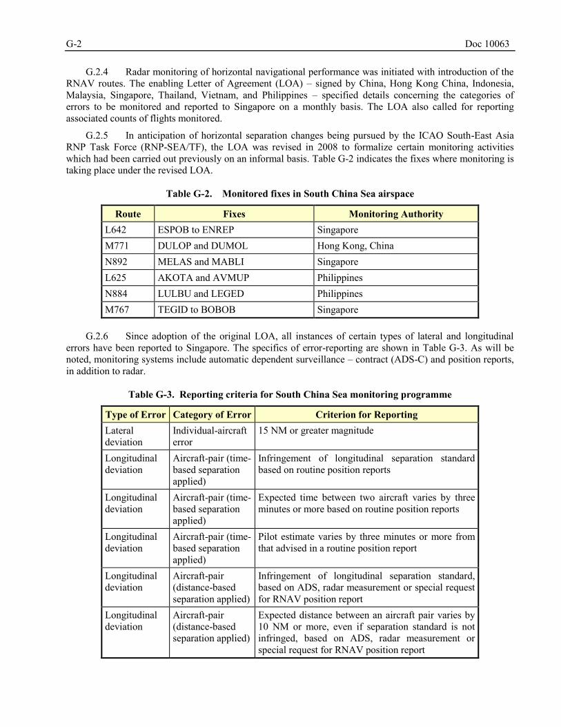
G-2 Doc 10063
G.2.4 Radar monitoring of horizontal navigational performance was initiated with introduction of the RNAV routes. The enabling Letter of Agreement (LOA) – signed by China, Hong Kong China, Indonesia, Malaysia, Singapore, Thailand, Vietnam, and Philippines – specified details concerning the categories of errors to be monitored and reported to Singapore on a monthly basis. The LOA also called for reporting associated counts of flights monitored.
G.2.5 In anticipation of horizontal separation changes being pursued by the ICAO South-East Asia RNP Task Force (RNP-SEA/TF), the LOA was revised in 2008 to formalize certain monitoring activities which had been carried out previously on an informal basis. Table G-2 indicates the fixes where monitoring is taking place under the revised LOA.
Table G-2. Monitored fixes in South China Sea airspace
Route Fixes Monitoring Authority L642 ESPOB to ENREP Singapore M771 DULOP and DUMOL Hong Kong, China N892 MELAS and MABLI Singapore L625 AKOTA and AVMUP Philippines N884 LULBU and LEGED Philippines M767 TEGID to BOBOB Singapore
G.2.6 Since adoption of the original LOA, all instances of certain types of lateral and longitudinal
errors have been reported to Singapore. The specifics of error-reporting are shown in Table G-3. As will be noted, monitoring systems include automatic dependent surveillance – contract (ADS-C) and position reports, in addition to radar.
Table G-3. Reporting criteria for South China Sea monitoring programme
Type of Error Category of Error Criterion for Reporting Lateral deviation
Individual-aircraft error
15 NM or greater magnitude
Longitudinal deviation
Aircraft-pair (time-based separation applied)
Infringement of longitudinal separation standard based on routine position reports
Longitudinal deviation
Aircraft-pair (time-based separation applied)
Expected time between two aircraft varies by three minutes or more based on routine position reports
Longitudinal deviation
Aircraft-pair (time-based separation applied)
Pilot estimate varies by three minutes or more from that advised in a routine position report
Longitudinal deviation
Aircraft-pair (distance-based separation applied)
Infringement of longitudinal separation standard, based on ADS, radar measurement or special request for RNAV position report
Longitudinal deviation
Aircraft-pair (distance-based separation applied)
Expected distance between an aircraft pair varies by 10 NM or more, even if separation standard is not infringed, based on ADS, radar measurement or special request for RNAV position report
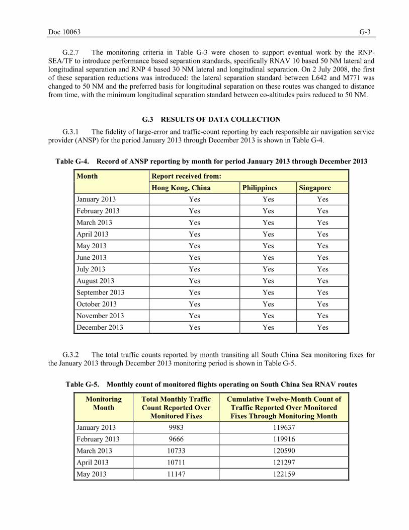
Doc 10063 G-3
G.2.7 The monitoring criteria in Table G-3 were chosen to support eventual work by the RNP-SEA/TF to introduce performance based separation standards, specifically RNAV 10 based 50 NM lateral and longitudinal separation and RNP 4 based 30 NM lateral and longitudinal separation. On 2 July 2008, the first of these separation reductions was introduced: the lateral separation standard between L642 and M771 was changed to 50 NM and the preferred basis for longitudinal separation on these routes was changed to distance from time, with the minimum longitudinal separation standard between co-altitudes pairs reduced to 50 NM.
G.3 RESULTS OF DATA COLLECTION
G.3.1 The fidelity of large-error and traffic-count reporting by each responsible air navigation service provider (ANSP) for the period January 2013 through December 2013 is shown in Table G-4.
Table G-4. Record of ANSP reporting by month for period January 2013 through December 2013
Month Report received from: Hong Kong, China Philippines Singapore
January 2013 Yes Yes Yes February 2013 Yes Yes Yes March 2013 Yes Yes Yes April 2013 Yes Yes Yes May 2013 Yes Yes Yes June 2013 Yes Yes Yes July 2013 Yes Yes Yes August 2013 Yes Yes Yes September 2013 Yes Yes Yes October 2013 Yes Yes Yes November 2013 Yes Yes Yes December 2013 Yes Yes Yes
G.3.2 The total traffic counts reported by month transiting all South China Sea monitoring fixes for the January 2013 through December 2013 monitoring period is shown in Table G-5.
Table G-5. Monthly count of monitored flights operating on South China Sea RNAV routes
Monitoring Month
Total Monthly Traffic Count Reported Over
Monitored Fixes
Cumulative Twelve-Month Count of Traffic Reported Over Monitored Fixes Through Monitoring Month
January 2013 9983 119637 February 2013 9666 119916 March 2013 10733 120590 April 2013 10711 121297 May 2013 11147 122159
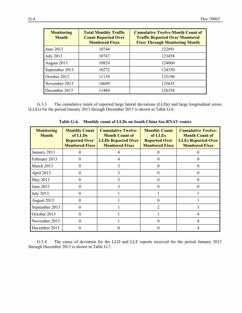
G-4 Doc 10063
Monitoring Month
Total Monthly Traffic Count Reported Over
Monitored Fixes
Cumulative Twelve-Month Count of Traffic Reported Over Monitored Fixes Through Monitoring Month
June 2013 10744 122891 July 2013 10767 123458 August 2013 10824 124060 September 2013 10272 124350 October 2013 11139 125190 November 2013 10689 125633 December 2013 11484 126358
G.3.3 The cumulative totals of reported large lateral deviations (LLDs) and large longitudinal errors (LLEs) for the period January 2013 through December 2013 is shown in Table G-6.
Table G-6. Monthly count of LLDs on South China Sea RNAV routes
Monitoring Month
Monthly Count of LLDs
Reported Over Monitored Fixes
Cumulative Twelve-Month Count of
LLDs Reported Over Monitored Fixes
Monthly Count of LLEs
Reported Over Monitored Fixes
Cumulative Twelve- Month Count of
LLEs Reported Over Monitored Fixes
January 2013 0 4 0 0 February 2013 0 4 0 0 March 2013 0 3 0 0 April 2013 0 3 0 0 May 2013 0 3 0 0 June 2013 0 3 0 0 July 2013 0 1 1 1 August 2013 0 1 0 1 September 2013 0 1 2 3 October 2013 0 1 1 4 November 2013 0 1 0 4 December 2013 0 0 0 4
G.3.4 The cause of deviation for the LLD and LLE reports received for the period January 2013 through December 2013 is shown in Table G-7.
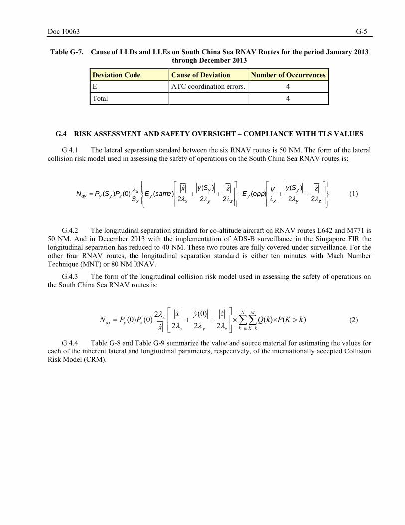
Doc 10063 G-5
Table G-7. Cause of LLDs and LLEs on South China Sea RNAV Routes for the period January 2013
through December 2013
Deviation Code Cause of Deviation Number of Occurrences E ATC coordination errors. 4 Total 4
G.4 RISK ASSESSMENT AND SAFETY OVERSIGHT – COMPLIANCE WITH TLS VALUES
G.4.1 The lateral separation standard between the six RNAV routes is 50 NM. The form of the lateral collision risk model used in assessing the safety of operations on the South China Sea RNAV routes is:
zy
y
xy
zy
y
xy
x
xzyyay
zSyVoppE
zSyxsameE
SPSPN
22
)()(
22
)(
2)()0()(
(1)
G.4.2 The longitudinal separation standard for co-altitude aircraft on RNAV routes L642 and M771 is 50 NM. And in December 2013 with the implementation of ADS-B surveillance in the Singapore FIR the longitudinal separation has reduced to 40 NM. These two routes are fully covered under surveillance. For the other four RNAV routes, the longitudinal separation standard is either ten minutes with Mach Number Technique (MNT) or 80 NM RNAV.
G.4.3 The form of the longitudinal collision risk model used in assessing the safety of operations on the South China Sea RNAV routes is:
)()(22
)0(2
2(0)(0) kKPkQzyx
xPPN
N
mk
M
kKzyx
xzyax
(2)
G.4.4 Table G-8 and Table G-9 summarize the value and source material for estimating the values for each of the inherent lateral and longitudinal parameters, respectively, of the internationally accepted Collision Risk Model (CRM).
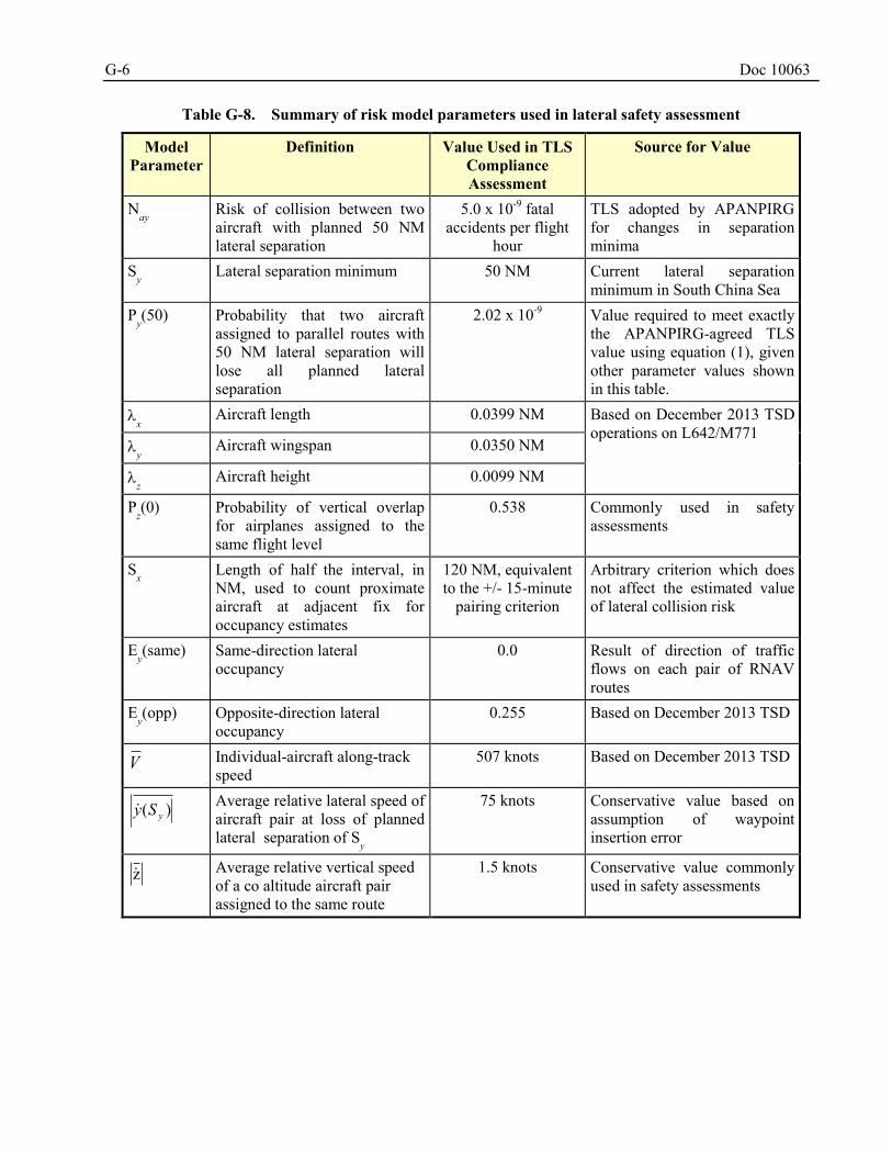
G-6 Doc 10063
Table G-8. Summary of risk model parameters used in lateral safety assessment
Model Parameter
Definition Value Used in TLS Compliance Assessment
Source for Value
Nay
Risk of collision between two aircraft with planned 50 NM lateral separation
5.0 x 10⁻⁹ fatal accidents per flight
hour
TLS adopted by APANPIRG for changes in separation minima
Sy Lateral separation minimum 50 NM Current lateral separation
minimum in South China Sea Py(50) Probability that two aircraft
assigned to parallel routes with 50 NM lateral separation will lose all planned lateral separation
2.02 x 10⁻⁹ Value required to meet exactly the APANPIRG-agreed TLS value using equation (1), given other parameter values shown in this table.
x Aircraft length 0.0399 NM Based on December 2013 TSD
operations on L642/M771 y Aircraft wingspan 0.0350 NM
z Aircraft height 0.0099 NM
Pz(0) Probability of vertical overlap
for airplanes assigned to the same flight level
0.538 Commonly used in safety assessments
Sx Length of half the interval, in
NM, used to count proximate aircraft at adjacent fix for occupancy estimates
120 NM, equivalent to the +/- 15-minute
pairing criterion
Arbitrary criterion which does not affect the estimated value of lateral collision risk
Ey(same) Same-direction lateral
occupancy 0.0 Result of direction of traffic
flows on each pair of RNAV routes
Ey(opp) Opposite-direction lateral
occupancy 0.255 Based on December 2013 TSD
V Individual-aircraft along-track speed
507 knots Based on December 2013 TSD
)( ySy
Average relative lateral speed of aircraft pair at loss of planned lateral separation of S
y
75 knots Conservative value based on assumption of waypoint insertion error
Average relative vertical speed of a co altitude aircraft pair assigned to the same route
1.5 knots Conservative value commonly used in safety assessments
z
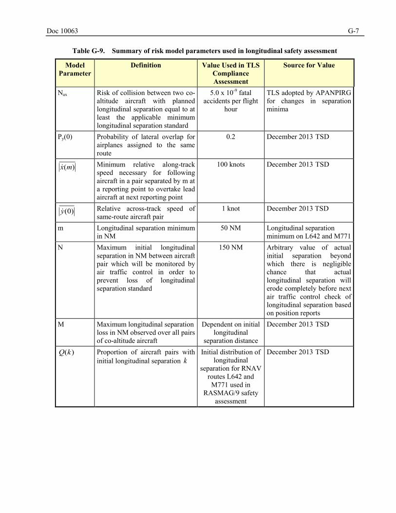
Doc 10063 G-7
Table G-9. Summary of risk model parameters used in longitudinal safety assessment
Model Parameter
Definition Value Used in TLS Compliance Assessment
Source for Value
Nax Risk of collision between two co-altitude aircraft with planned longitudinal separation equal to at least the applicable minimum longitudinal separation standard
5.0 x 10⁻⁹ fatal accidents per flight
hour
TLS adopted by APANPIRG for changes in separation minima
Py(0) Probability of lateral overlap for airplanes assigned to the same route
0.2 December 2013 TSD
)(mx Minimum relative along-track speed necessary for following aircraft in a pair separated by m at a reporting point to overtake lead aircraft at next reporting point
100 knots December 2013 TSD
)0(y Relative across-track speed of same-route aircraft pair
1 knot December 2013 TSD
m Longitudinal separation minimum in NM
50 NM Longitudinal separation minimum on L642 and M771
N Maximum initial longitudinal separation in NM between aircraft pair which will be monitored by air traffic control in order to prevent loss of longitudinal separation standard
150 NM Arbitrary value of actual initial separation beyond which there is negligible chance that actual longitudinal separation will erode completely before next air traffic control check of longitudinal separation based on position reports
M Maximum longitudinal separation loss in NM observed over all pairs of co-altitude aircraft
Dependent on initial longitudinal
separation distance
December 2013 TSD
)(kQ Proportion of aircraft pairs with initial longitudinal separation k
Initial distribution of longitudinal
separation for RNAV routes L642 and M771 used in
RASMAG/9 safety assessment
December 2013 TSD
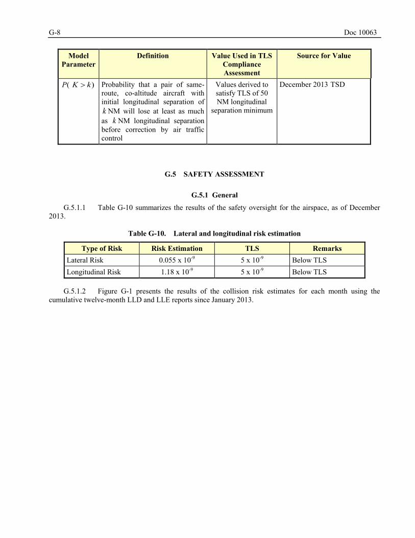
G-8 Doc 10063
Model Parameter
Definition Value Used in TLS Compliance Assessment
Source for Value
(P )kK Probability that a pair of same-route, co-altitude aircraft with initial longitudinal separation of k NM will lose at least as much as k NM longitudinal separation before correction by air traffic control
Values derived to satisfy TLS of 50 NM longitudinal
separation minimum
December 2013 TSD
G.5 SAFETY ASSESSMENT
G.5.1 General
G.5.1.1 Table G-10 summarizes the results of the safety oversight for the airspace, as of December 2013.
Table G-10. Lateral and longitudinal risk estimation
Type of Risk Risk Estimation TLS Remarks Lateral Risk 0.055 x 10⁻⁹ 5 x 10⁻⁹ Below TLS Longitudinal Risk 1.18 x 10⁻⁹ 5 x 10⁻⁹ Below TLS
G.5.1.2 Figure G-1 presents the results of the collision risk estimates for each month using the cumulative twelve-month LLD and LLE reports since January 2013.
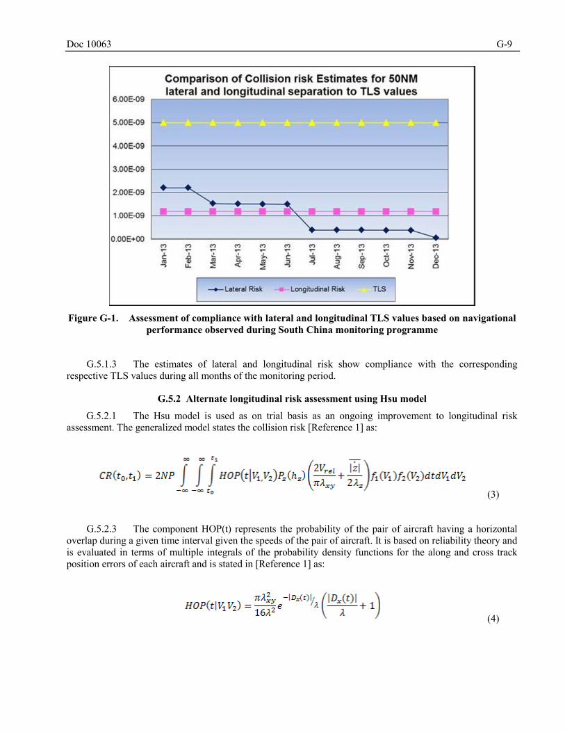
Doc 10063 G-9
Figure G-1. Assessment of compliance with lateral and longitudinal TLS values based on navigational
performance observed during South China monitoring programme
G.5.1.3 The estimates of lateral and longitudinal risk show compliance with the corresponding respective TLS values during all months of the monitoring period.
G.5.2 Alternate longitudinal risk assessment using Hsu model
G.5.2.1 The Hsu model is used as on trial basis as an ongoing improvement to longitudinal risk assessment. The generalized model states the collision risk [Reference 1] as:
(3)
G.5.2.3 The component HOP(t) represents the probability of the pair of aircraft having a horizontal overlap during a given time interval given the speeds of the pair of aircraft. It is based on reliability theory and is evaluated in terms of multiple integrals of the probability density functions for the along and cross track position errors of each aircraft and is stated in [Reference 1] as:
(4)
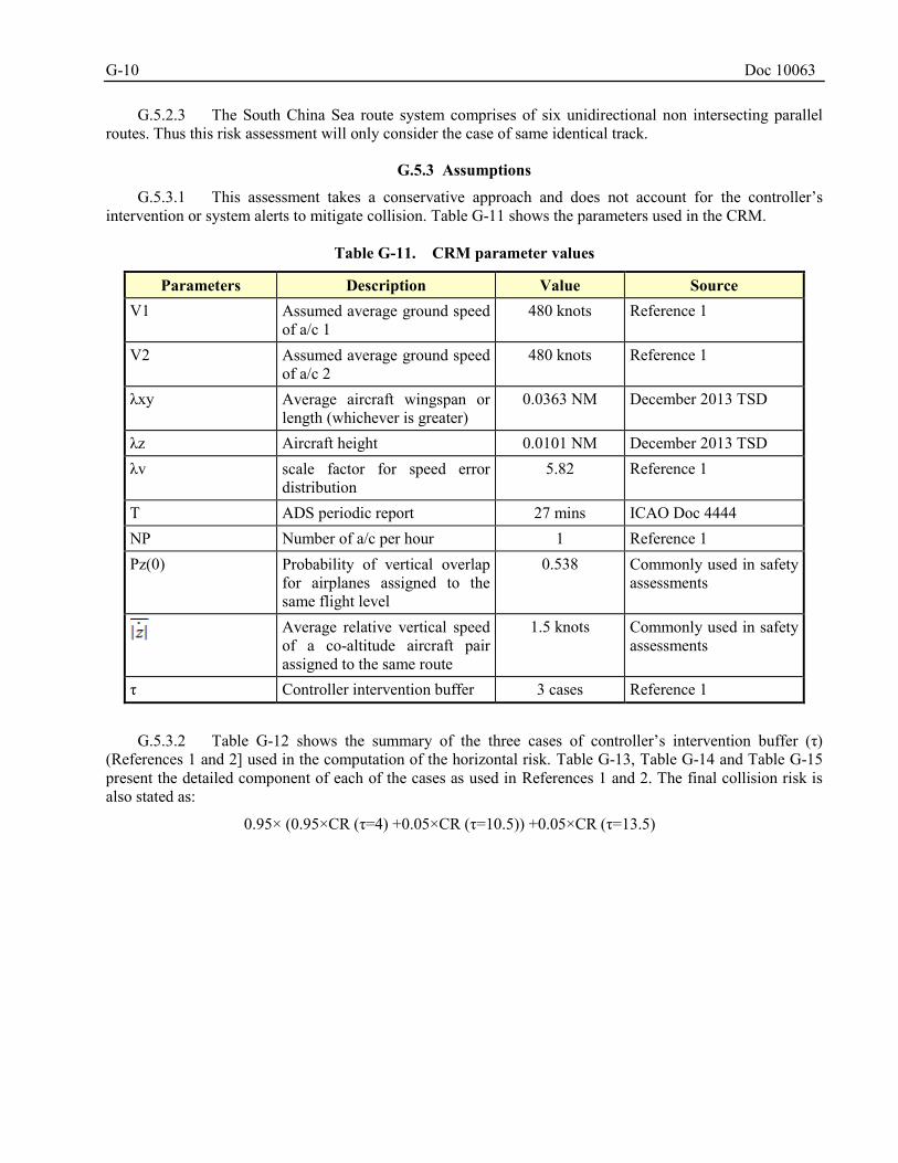
G-10 Doc 10063
G.5.2.3 The South China Sea route system comprises of six unidirectional non intersecting parallel routes. Thus this risk assessment will only consider the case of same identical track.
G.5.3 Assumptions
G.5.3.1 This assessment takes a conservative approach and does not account for the controller’s intervention or system alerts to mitigate collision. Table G-11 shows the parameters used in the CRM.
Table G-11. CRM parameter values
Parameters Description Value Source V1 Assumed average ground speed
of a/c 1 480 knots Reference 1
V2 Assumed average ground speed of a/c 2
480 knots Reference 1
λxy Average aircraft wingspan or length (whichever is greater)
0.0363 NM December 2013 TSD
λz Aircraft height 0.0101 NM December 2013 TSD λv scale factor for speed error
distribution 5.82 Reference 1
T ADS periodic report 27 mins ICAO Doc 4444 NP Number of a/c per hour 1 Reference 1 Pz(0) Probability of vertical overlap
for airplanes assigned to the same flight level
0.538
Commonly used in safety assessments
Average relative vertical speed of a co-altitude aircraft pair assigned to the same route
1.5 knots
Commonly used in safety assessments
τ Controller intervention buffer 3 cases Reference 1
G.5.3.2 Table G-12 shows the summary of the three cases of controller’s intervention buffer (τ) (References 1 and 2] used in the computation of the horizontal risk. Table G-13, Table G-14 and Table G-15 present the detailed component of each of the cases as used in References 1 and 2. The final collision risk is also stated as:
0.95× (0.95×CR (τ=4) +0.05×CR (τ=10.5)) +0.05×CR (τ=13.5)
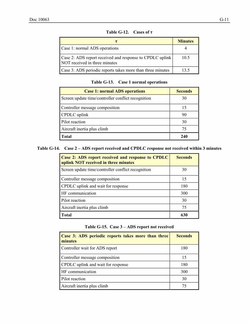
Doc 10063 G-11
Table G-12. Cases of τ
τ Minutes Case 1: normal ADS operations 4
Case 2: ADS report received and response to CPDLC uplink NOT received in three minutes
10.5
Case 3: ADS periodic reports takes more than three minutes 13.5
Table G-13. Case 1 normal operations
Case 1: normal ADS operations Seconds Screen update time/controller conflict recognition 30
Controller message composition 15 CPDLC uplink 90 Pilot reaction 30 Aircraft inertia plus climb 75
Total 240
Table G-14. Case 2 – ADS report received and CPDLC response not received within 3 minutes
Case 2: ADS report received and response to CPDLC uplink NOT received in three minutes
Seconds
Screen update time/controller conflict recognition 30
Controller message composition 15 CPDLC uplink and wait for response 180 HF communication 300 Pilot reaction 30 Aircraft inertia plus climb 75
Total 630
Table G-15. Case 3 – ADS report not received
Case 3: ADS periodic reports takes more than three minutes
Seconds
Controller wait for ADS report 180
Controller message composition 15 CPDLC uplink and wait for response 180 HF communication 300 Pilot reaction 30 Aircraft inertia plus climb 75
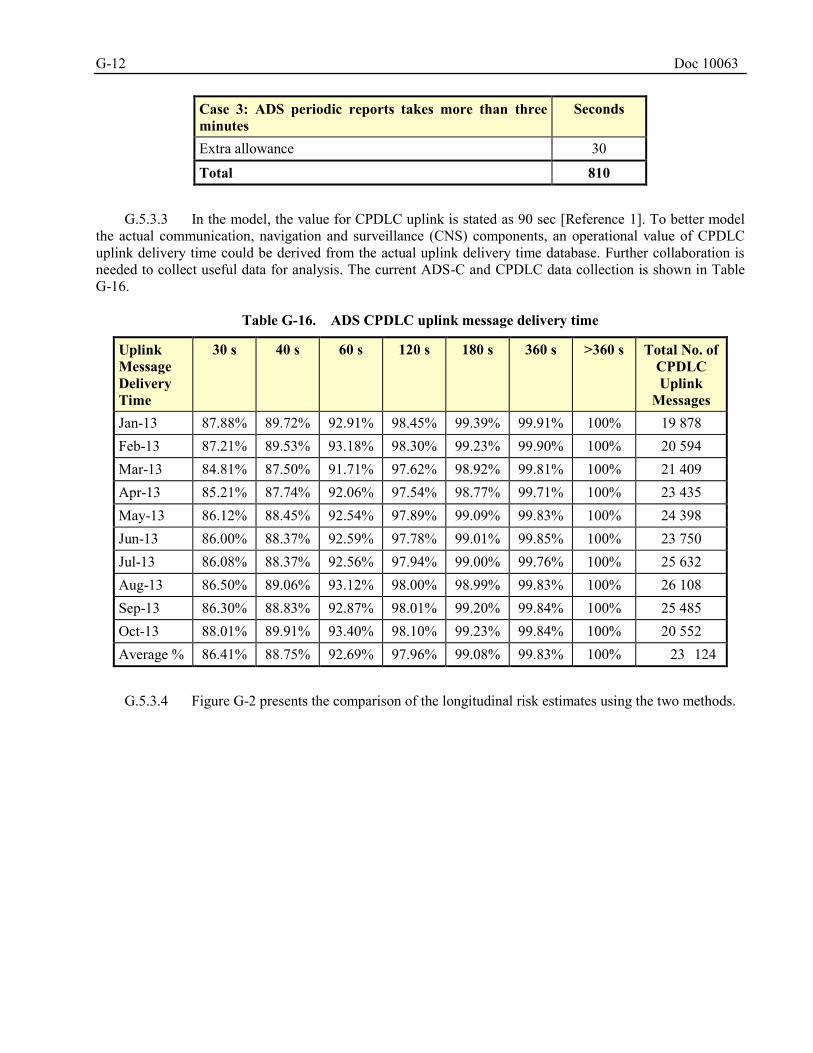
G-12 Doc 10063
Case 3: ADS periodic reports takes more than three minutes
Seconds
Extra allowance 30
Total 810
G.5.3.3 In the model, the value for CPDLC uplink is stated as 90 sec [Reference 1]. To better model
the actual communication, navigation and surveillance (CNS) components, an operational value of CPDLC uplink delivery time could be derived from the actual uplink delivery time database. Further collaboration is needed to collect useful data for analysis. The current ADS-C and CPDLC data collection is shown in Table G-16.
Table G-16. ADS CPDLC uplink message delivery time
Uplink Message Delivery Time
30 s 40 s 60 s 120 s 180 s 360 s >360 s Total No. of CPDLC Uplink
Messages Jan-13 87.88% 89.72% 92.91% 98.45% 99.39% 99.91% 100% 19 878 Feb-13 87.21% 89.53% 93.18% 98.30% 99.23% 99.90% 100% 20 594 Mar-13 84.81% 87.50% 91.71% 97.62% 98.92% 99.81% 100% 21 409 Apr-13 85.21% 87.74% 92.06% 97.54% 98.77% 99.71% 100% 23 435 May-13 86.12% 88.45% 92.54% 97.89% 99.09% 99.83% 100% 24 398 Jun-13 86.00% 88.37% 92.59% 97.78% 99.01% 99.85% 100% 23 750 Jul-13 86.08% 88.37% 92.56% 97.94% 99.00% 99.76% 100% 25 632 Aug-13 86.50% 89.06% 93.12% 98.00% 98.99% 99.83% 100% 26 108 Sep-13 86.30% 88.83% 92.87% 98.01% 99.20% 99.84% 100% 25 485 Oct-13 88.01% 89.91% 93.40% 98.10% 99.23% 99.84% 100% 20 552 Average % 86.41% 88.75% 92.69% 97.96% 99.08% 99.83% 100% 23 124
G.5.3.4 Figure G-2 presents the comparison of the longitudinal risk estimates using the two methods.
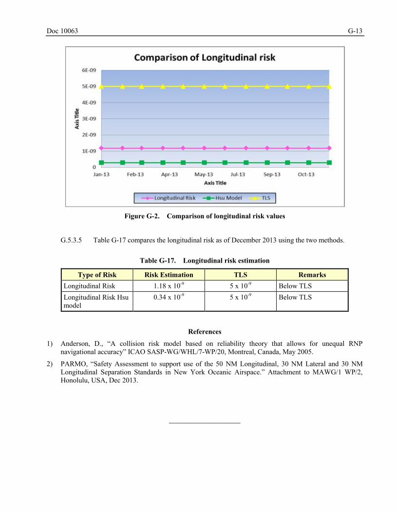
Doc 10063 G-13
Figure G-2. Comparison of longitudinal risk values
G.5.3.5 Table G-17 compares the longitudinal risk as of December 2013 using the two methods.
Table G-17. Longitudinal risk estimation
Type of Risk Risk Estimation TLS Remarks Longitudinal Risk 1.18 x 10⁻⁹ 5 x 10⁻⁹ Below TLS Longitudinal Risk Hsu model
0.34 x 10⁻⁹ 5 x 10⁻⁹ Below TLS
References
1) Anderson, D., “A collision risk model based on reliability theory that allows for unequal RNP navigational accuracy” ICAO SASP-WG/WHL/7-WP/20, Montreal, Canada, May 2005.
2) PARMO, “Safety Assessment to support use of the 50 NM Longitudinal, 30 NM Lateral and 30 NM Longitudinal Separation Standards in New York Oceanic Airspace.” Attachment to MAWG/1 WP/2, Honolulu, USA, Dec 2013.
______________________

Doc 10063 H-1
Appendix H EXAMPLE SAFETY ASSESSMENT – HORIZONTAL SEPARATION
REDUCTION IN NEW YORK OCEANIC AIRSPACE
INTRODUCTION H.1
H.1.1 The Federal Aviation Administration’s (FAA’s) Pacific Approvals Registry and Monitoring Organization (PARMO), serves as an En-route Monitoring Agency (EMA) for the Anchorage and Oakland Oceanic Flight Information Regions (FIRs) where the 50 NM longitudinal, 30 NM lateral, and 30 NM longitudinal separation minima have been implemented. These implementations were made possible with the introduction of a new ATC automation system and improvements made in the communication, navigation, and surveillance (CNS) systems by the airspace users and service providers. The reduced horizontal separation minima are available for suitably equipped aircraft pairs.
H.1.2 The purpose of this appendix is to present an example of a safety assessment, as conducted by PARMO for New York oceanic airspace, together with the collision risk models used, to assess compliance with the ICAO Target Level of Safety (TLS) values for the maintenance of lateral and longitudinal separation standards.
BACKGROUND H.2
H.2.1 In combination with data collected from the area of application, the ICAO-endorsed collision risk methodology is used to prepare an estimate of the collision risk upon introduction of the 50 NM longitudinal, 30 NM lateral, and longitudinal separation minima. These risk estimates will be compared to the TLS of 5 x 10⁻⁹ fatal accidents per flight hour (fapfh) due, separately, to the loss of 50 NM longitudinal, 30 NM lateral, and 30 NM longitudinal separation, following the guidelines for implementing these separation minima in international airspace contained in ICAO Docs 9689 and 9869.
H.2.2 In New York oceanic airspace, the controller decision support system is the FAA’s automated oceanic air traffic control (ATC) system, Ocean21. The decision support system is used to project a conflict-free path for an aircraft between it and others with applicable separation minima. The Ocean21 system is fully compliant with the requirements contained within ICAO Doc 4444 regarding the application of ADS-C and controller-pilot data link communications (CPDLC) in support of 50 NM longitudinal, 30 NM lateral, and 30 NM longitudinal separation standards, such as:
a) establishing ADS-C contracts with an appropriate periodic update rate for suitably approved aircraft;
b) establishing a lateral deviation event contract set to 5 NM; and
c) reversion to an alternate procedural separation if ADS-C message is overdue by three minutes and six minutes have elapsed since controller began attempting to establish communication.
H.2.3 The operator and aircraft requirements for the use of the 50 NM longitudinal separation standard include approval for Required Navigation Performance (RNP)-10 along with direct controller-pilot communications (DCPC). The operator and aircraft requirements for the use of 30 NM lateral and 30 NM longitudinal separation standards include approval for RNP 4 along with DCPC. The use of satellite data link communications involving CPDLC is considered to be DCPC as stated in ICAO Doc 4444, paragraph 5.4.2.6.2.2. In addition, the application of the reduced separation will require the communication systems to meet the Required Communication Performance (RCP) Type 240 and Required Surveillance Performance (RSP) Type 180 specifications contained in ICAO Doc 9869.
H.2.4 As part of the safety assessment, this appendix provides verification that the ADS-C requirements contained in ICAO Doc 4444, as they pertain to the application of the 50 NM longitudinal, 30 NM lateral, and 30 NM longitudinal separation minima, are satisfied in New York oceanic airspace. In
Stephanie.Beritsky
Highlight
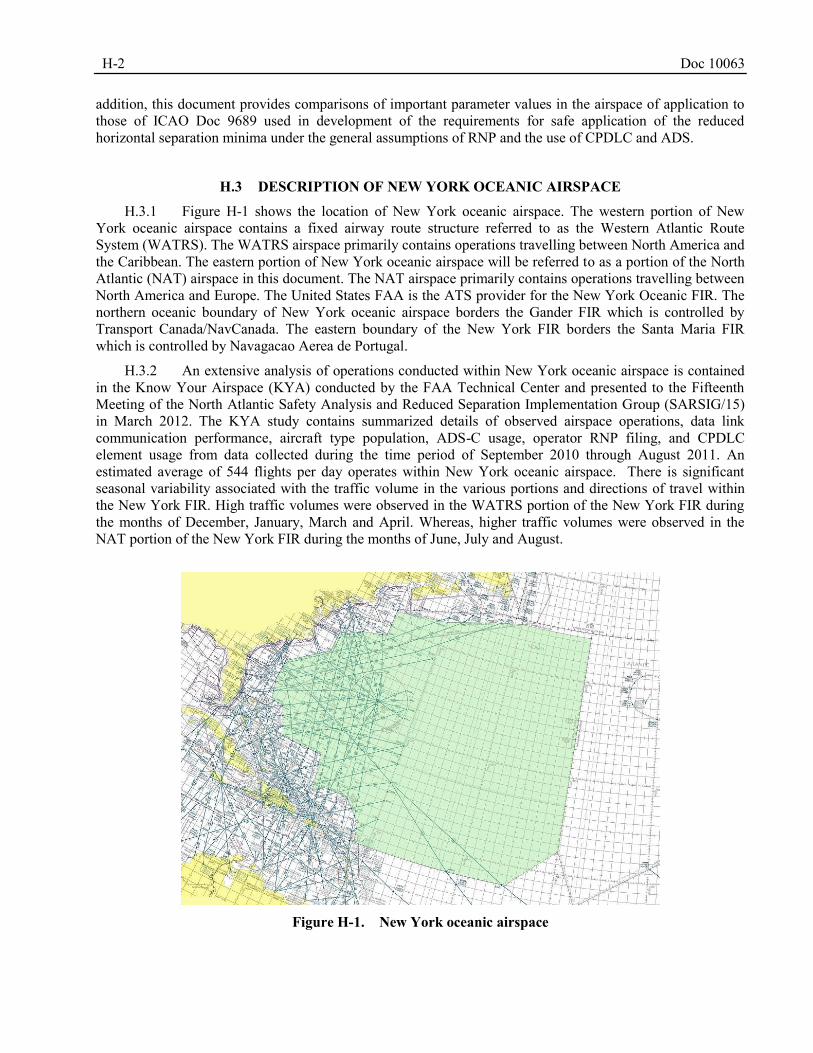
H-2 Doc 10063
addition, this document provides comparisons of important parameter values in the airspace of application to those of ICAO Doc 9689 used in development of the requirements for safe application of the reduced horizontal separation minima under the general assumptions of RNP and the use of CPDLC and ADS.
DESCRIPTION OF NEW YORK OCEANIC AIRSPACE H.3
H.3.1 Figure H-1 shows the location of New York oceanic airspace. The western portion of New York oceanic airspace contains a fixed airway route structure referred to as the Western Atlantic Route System (WATRS). The WATRS airspace primarily contains operations travelling between North America and the Caribbean. The eastern portion of New York oceanic airspace will be referred to as a portion of the North Atlantic (NAT) airspace in this document. The NAT airspace primarily contains operations travelling between North America and Europe. The United States FAA is the ATS provider for the New York Oceanic FIR. The northern oceanic boundary of New York oceanic airspace borders the Gander FIR which is controlled by Transport Canada/NavCanada. The eastern boundary of the New York FIR borders the Santa Maria FIR which is controlled by Navagacao Aerea de Portugal.
H.3.2 An extensive analysis of operations conducted within New York oceanic airspace is contained in the Know Your Airspace (KYA) conducted by the FAA Technical Center and presented to the Fifteenth Meeting of the North Atlantic Safety Analysis and Reduced Separation Implementation Group (SARSIG/15) in March 2012. The KYA study contains summarized details of observed airspace operations, data link communication performance, aircraft type population, ADS-C usage, operator RNP filing, and CPDLC element usage from data collected during the time period of September 2010 through August 2011. An estimated average of 544 flights per day operates within New York oceanic airspace. There is significant seasonal variability associated with the traffic volume in the various portions and directions of travel within the New York FIR. High traffic volumes were observed in the WATRS portion of the New York FIR during the months of December, January, March and April. Whereas, higher traffic volumes were observed in the NAT portion of the New York FIR during the months of June, July and August.
Figure H-1. New York oceanic airspace
Doc 10063 H-3
OPERATORS AND AIRCRAFT TYPES ELIGIBLE FOR THE REDUCED HORIZONTAL H.4
SEPARATION MINIMA
H.4.1 An operator and aircraft must have State approval for RNP 4 operations, and be equipped with CPDLC and ADS-C in order to be eligible for application of the 30 NM lateral and 30 NM longitudinal separation minima. The 50 NM longitudinal separation minimum requires that an operator and aircraft have State approval for RNP 10 operations and be equipped with CPDLC and ADS-C. All United States registered aircraft require a separate approval for data link operations.
H.4.2 In addition, the application of the reduced longitudinal separation will require the performance of the communication systems to meet the RCP Type 240 and RSP Type 180 specifications as contained in ICAO Doc 9869.
H.4.3 Table H-1 provides the observed proportions of operations eligible for the 50 NM longitudinal, 30 NM lateral, and 30 NM longitudinal separation minima. Operations using ADS-C for position reporting and indicating RNP 4 in the filed flight plan are eligible for the 30 NM lateral and 30 NM longitudinal separation minima. Operations using ADS-C for position reporting and indicating RNP 10 or RNP 4 in the filed flight plan are eligible for the 50 NM longitudinal separation minimum. It is noted that the RNP 4 operations not using ADS-C in Table H-1 are typically State aircraft RNP 4 operations without data link.
H.4.4 It is noted that some operations occur in both the WATRS and NAT portions of the airspace, these operations are counted in both the NAT and WATRS total number of operations. Because of this, the total number of observed operations indicated in the lower right corner of Table H-1 (52 718), is not equal to the sum of the number of operations observed in the NAT (24 421) and WATRS (44 270).
Table H-1. Proportions of operations indicating RNP 4/RNP 10 in the filed flight plan and utilizing
ADS-C in New York oceanic airspace; March – May 2012
NAT WATRS ZNY ADS-C Non ADS-C ADS-C Non ADS-C ADS-C Non ADS-C
RNP 4 5.90% 2.98% 4.17% 2.39% 3.90% 2.32% RNP 10 50.47% 38.06% 22.91% 68.59% 27.05% 64.60% Non RNP 10 0.00% 0.02% 0.00% 0.07% 0.00% 0.07% Total Number of
Operations
24 421 44 270 52 718
H.4.5 Table H-1 shows that a majority of the operations in New York oceanic airspace are eligible for the 50 NM longitudinal separation minimum. In the NAT and WATRS portions of the airspace, roughly 50 and 23 per cent, respectively, of the traffic use ADS-C and file RNP 10 or better. Fewer operations are eligible for the application of the 30 NM lateral and 30 NM longitudinal separation minima, roughly 6 and 4 per cent of operations within the NAT and WATRS portions, respectively, meet the requirements for the application of the 30 NM horizontal standards.
H.4.6 Table H-2 displays the proportions of aircraft types, in terms of numbers of operations, observed using ADS-C for position reporting and indicating RNP 4 or RNP 10 in the filed flight plan in New York oceanic airspace. These data were collected during the months of March through May 2012. It can be assumed that operations which indicate RNP 4 approval also satisfy the performance requirements for RNP 10, therefore the RNP 10 data on the right side of Table H-2 also includes operations that indicated RNP 4 approval.
H-4 Doc 10063
H.4.7 The top two aircraft types, A332 and B777-200, represent approximately 2 per cent of the operations eligible for the 30 NM lateral and longitudinal separation minima. These same aircraft types, A332 and B772, represent more than 11 per cent of the operations eligible for the 50 NM longitudinal separation minimum.
H.4.8 The top five aircraft types indicating RNP 10 and using ADS-C represent roughly 21 per cent of all operations which are eligible for the 50 NM longitudinal separation minimum. The top five aircraft types indicating RNP 4 and using ADS-C represent approximately 3 per cent of all operations which are eligible for the 50 NM longitudinal separation minimum.
Table H-2. Aircraft types indicating RNP 4/RNP 10 in the filed flight plan and utilizing ADS-C in New
York oceanic airspace
RNP 10 Aircraft Type
Proportion of all Operations
Cumulative Proportion
Aircraft Type
Proportion of All Operations
Cumulative Proportion
A332 1.17% 1.17% B772 5.89% 5.89% B772 0.80% 1.97% A332 5.70% 11.60% A333 0.75% 2.72% B744 3.68% 15.27% B764 0.31% 3.02% A333 3.09% 18.36% C17 0.17% 3.20% A346 3.00% 21.36% C5/H 0.15% 3.35% A343 2.64% 24.00% MD11 0.10% 3.45% B77W 1.89% 25.89% A345 0.09% 3.54% B763 1.26% 27.16% K35R 0.08% 3.62% B764 1.23% 28.39% A343 0.05% 3.67% B77L 0.47% 28.86% GLF5 0.05% 3.72% C17 0.38% 29.24% B744 0.05% 3.77% B752 0.26% 29.50% A388 0.04% 3.80% GLF5 0.23% 29.73% B762 0.03% 3.83% MD11 0.21% 29.94% B77W 0.02% 3.85% C5/H 0.20% 30.14%
SAFETY ASSESSMENT METHODOLOGY H.5
H.5.1 General
H.5.1.1 In accordance with the requirements and guidance of ICAO Docs 4444, 9689 and 9869, the safety assessment provides estimates of the risk of collision which will pertain when 50 NM longitudinal, 30 NM lateral, and 30 NM longitudinal separation minima are applied in New York oceanic airspace and compares this risk to the specified Target Level of Safety (TLS).
H.5.1.2 As stated in ICAO Doc 9689, paragraph 3.2.1, the value of the TLS which applies to both the lateral and longitudinal dimensions is 5 x 10⁻⁹ fatal accidents per flight hour (fapfh). This is also in accordance
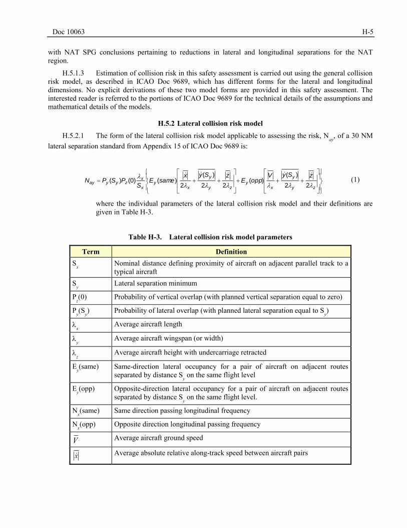
Doc 10063 H-5
with NAT SPG conclusions pertaining to reductions in lateral and longitudinal separations for the NAT region.
H.5.1.3 Estimation of collision risk in this safety assessment is carried out using the general collision risk model, as described in ICAO Doc 9689, which has different forms for the lateral and longitudinal dimensions. No explicit derivations of these two model forms are provided in this safety assessment. The interested reader is referred to the portions of ICAO Doc 9689 for the technical details of the assumptions and mathematical details of the models.
H.5.2 Lateral collision risk model
H.5.2.1 The form of the lateral collision risk model applicable to assessing the risk, Nay
, of a 30 NM lateral separation standard from Appendix 15 of ICAO Doc 9689 is:
zy
y
xy
zy
y
xy
x
xzyyay
zSyVoppE
zSyxsameE
SPSPN
22
)()(
22
)(
2)()0()(
(1)
where the individual parameters of the lateral collision risk model and their definitions are given in Table H-3.
Table H-3. Lateral collision risk model parameters
Term Definition Sx Nominal distance defining proximity of aircraft on adjacent parallel track to a
typical aircraft Sy Lateral separation minimum
Pz(0) Probability of vertical overlap (with planned vertical separation equal to zero)
Py(Sy) Probability of lateral overlap (with planned lateral separation equal to S
y)
x Average aircraft length
y Average aircraft wingspan (or width)
z Average aircraft height with undercarriage retracted
Ey(same) Same-direction lateral occupancy for a pair of aircraft on adjacent routes
separated by distance Sy on the same flight level
Ey(opp) Opposite-direction lateral occupancy for a pair of aircraft on adjacent routes
separated by distance Sy on the same flight level.
Nx(same) Same direction passing longitudinal frequency
Nx(opp) Opposite direction longitudinal passing frequency
V Average aircraft ground speed
x Average absolute relative along-track speed between aircraft pairs
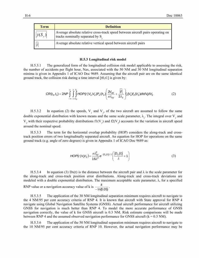
H-6 Doc 10063
Term Definition
)( ySy
Average absolute relative cross-track speed between aircraft pairs operating on tracks nominally separated by S
y
z Average absolute relative vertical speed between aircraft pairs
H.5.3 Longitudinal risk model
H.5.3.1 The generalized form of the longitudinal collision risk model applicable to assessing the risk, the number of accidents per flight hour, Nax, associated with the 50 NM and 30 NM longitudinal separation minima is given in Appendix 1 of ICAO Doc 9689. Assuming that the aircraft pair are on the same identical ground track, the collision risk during a time interval [t0,t1] is given by:
2122112110 )()(2
2)(),|(2),(
1
0
dVdtdVVfVfzV
hPVVtHOPNPttCR
t
t zxy
relzz
(2)
H.5.3.2 In equation (2) the speeds, V1 and V
2, of the two aircraft are assumed to follow the same
double exponential distribution with known means and the same scale parameter, λv. The integral over V
1 and
V2 with their respective probability distributions f1(V
1) and f2(V
2) accounts for the variation in aircraft speed
around the nominal speed.
H.5.3.3 The term for the horizontal overlap probability (HOP) considers the along-track and cross-track position errors of two longitudinally separated aircraft. An equation for HOP for operations on the same ground track (e.g. angle of zero degrees) is given in Appendix 1 of ICAO Doc 9689 as:
1
)(
16|
/)(
2
2
21
tDeVVtHOP
xtDxy x (3)
H.5.3.4 In equation (3) Dx(t) is the distance between the aircraft pair and λ is the scale parameter for the along-track and cross-track position error distributions. Along-track and cross-track deviations are modeled with a double exponential distribution. The maximum acceptable scale parameter, λ, for a specified
RNP value or a navigation accuracy value of k is )05.0ln(
k .
H.5.3.5 The application of the 30 NM longitudinal separation minimum requires aircraft to navigate to the 4 NM/95 per cent accuracy criteria of RNP 4. It is known that aircraft with State approval for RNP 4 navigate using Global Navigation Satellite Systems (GNSS). Actual aircraft performance for aircraft utilizing GNSS for navigation is much better than RNP 4. To model the more accurate performance of GNSS navigation correctly, the value of k for GNSS aircraft is 0.3 NM. Risk estimate comparisons will be made between RNP 4 and the assumed observed navigation performance for GNSS aircraft (k = 0.3 NM).
H.5.3.6 The application of the 50 NM longitudinal separation minimum requires aircraft to navigate to the 10 NM/95 per cent accuracy criteria of RNP 10. However, the actual navigation performance may be
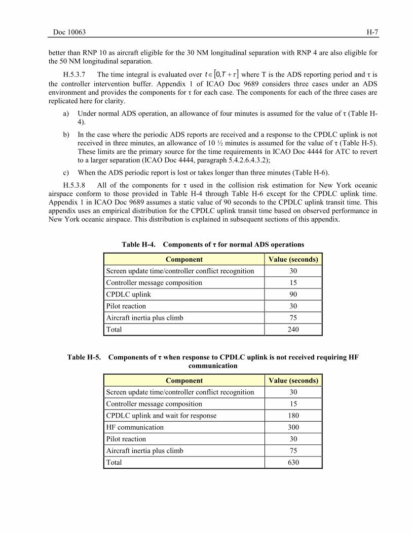
Doc 10063 H-7
better than RNP 10 as aircraft eligible for the 30 NM longitudinal separation with RNP 4 are also eligible for the 50 NM longitudinal separation.
H.5.3.7 The time integral is evaluated over Tt ,0 where T is the ADS reporting period and τ is the controller intervention buffer. Appendix 1 of ICAO Doc 9689 considers three cases under an ADS environment and provides the components for τ for each case. The components for each of the three cases are replicated here for clarity.
a) Under normal ADS operation, an allowance of four minutes is assumed for the value of τ (Table H-4).
b) In the case where the periodic ADS reports are received and a response to the CPDLC uplink is not received in three minutes, an allowance of 10 ½ minutes is assumed for the value of τ (Table H-5). These limits are the primary source for the time requirements in ICAO Doc 4444 for ATC to revert to a larger separation (ICAO Doc 4444, paragraph 5.4.2.6.4.3.2);
c) When the ADS periodic report is lost or takes longer than three minutes (Table H-6).
H.5.3.8 All of the components for τ used in the collision risk estimation for New York oceanic airspace conform to those provided in Table H-4 through Table H-6 except for the CPDLC uplink time. Appendix 1 in ICAO Doc 9689 assumes a static value of 90 seconds to the CPDLC uplink transit time. This appendix uses an empirical distribution for the CPDLC uplink transit time based on observed performance in New York oceanic airspace. This distribution is explained in subsequent sections of this appendix.
Table H-4. Components of τ for normal ADS operations
Component Value (seconds) Screen update time/controller conflict recognition 30 Controller message composition 15 CPDLC uplink 90 Pilot reaction 30 Aircraft inertia plus climb 75 Total 240
Table H-5. Components of τ when response to CPDLC uplink is not received requiring HF
communication
Component Value (seconds) Screen update time/controller conflict recognition 30 Controller message composition 15 CPDLC uplink and wait for response 180 HF communication 300 Pilot reaction 30 Aircraft inertia plus climb 75 Total 630
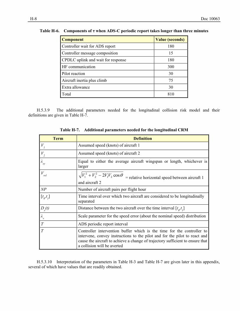
H-8 Doc 10063
Table H-6. Components of τ when ADS-C periodic report takes longer than three minutes
Component Value (seconds) Controller wait for ADS report 180 Controller message composition 15 CPDLC uplink and wait for response 180 HF communication 300 Pilot reaction 30 Aircraft inertia plus climb 75 Extra allowance 30 Total 810
H.5.3.9 The additional parameters needed for the longitudinal collision risk model and their definitions are given in Table H-7.
Table H-7. Additional parameters needed for the longitudinal CRM
Term Definition V1 Assumed speed (knots) of aircraft 1
V2 Assumed speed (knots) of aircraft 2
λxy
Equal to either the average aircraft wingspan or length, whichever is larger
Vrel
cos2 212
22
1 VVVV = relative horizontal speed between aircraft 1 and aircraft 2
NP Number of aircraft pairs per flight hour [t0,t1] Time interval over which two aircraft are considered to be longitudinally
separated Dx(t) Distance between the two aircraft over the time interval [t
0,t1]
λv Scale parameter for the speed error (about the nominal speed) distribution
T ADS periodic report interval Τ Controller intervention buffer which is the time for the controller to
intervene, convey instructions to the pilot and for the pilot to react and cause the aircraft to achieve a change of trajectory sufficient to ensure that a collision will be averted
H.5.3.10 Interpretation of the parameters in Table H-3 and Table H-7 are given later in this appendix, several of which have values that are readily obtained.
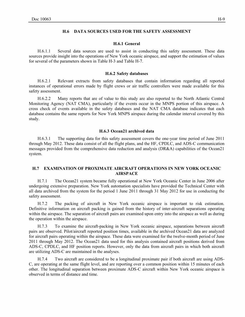
Doc 10063 H-9
DATA SOURCES USED FOR THE SAFETY ASSESSMENT H.6
H.6.1 General
H.6.1.1 Several data sources are used to assist in conducting this safety assessment. These data sources provide insight into the operations of New York oceanic airspace, and support the estimation of values for several of the parameters shown in Table H-3 and Table H-7.
H.6.2 Safety databases
H.6.2.1 Relevant extracts from safety databases that contain information regarding all reported instances of operational errors made by flight crews or air traffic controllers were made available for this safety assessment.
H.6.2.2 Many reports that are of value to this study are also reported to the North Atlantic Central Monitoring Agency (NAT CMA), particularly if the events occur in the MNPS portion of this airspace. A cross check of events available in the safety databases and the NAT CMA database indicates that each database contains the same reports for New York MNPS airspace during the calendar interval covered by this study.
H.6.3 Ocean21 archived data
H.6.3.1 The supporting data for this safety assessment covers the one-year time period of June 2011 through May 2012. These data consist of all the flight plans, and the HF, CPDLC, and ADS-C communication messages provided from the comprehensive data reduction and analysis (DR&A) capabilities of the Ocean21 system.
EXAMINATION OF PROXIMATE AIRCRAFT OPERATIONS IN NEW YORK OCEANIC H.7
AIRSPACE
H.7.1 The Ocean21 system became fully operational at New York Oceanic Center in June 2006 after undergoing extensive preparation. New York automation specialists have provided the Technical Center with all data archived from the system for the period 1 June 2011 through 31 May 2012 for use in conducting the safety assessment.
H.7.2 The packing of aircraft in New York oceanic airspace is important to risk estimation. Definitive information on aircraft packing is gained from the history of inter-aircraft separations operating within the airspace. The separation of aircraft pairs are examined upon entry into the airspace as well as during the operation within the airspace.
H.7.3 To examine the aircraft-packing in New York oceanic airspace, separations between aircraft pairs are observed. Pilot/aircraft reported position times, available in the archived Ocean21 data are analyzed for aircraft pairs operating within the airspace. These data were examined for the twelve-month period of June 2011 through May 2012. The Ocean21 data used for this analysis contained aircraft positions derived from ADS-C, CPDLC, and HF position reports. However, only the data from aircraft pairs in which both aircraft are utilizing ADS-C are maintained in the analyses.
H.7.4 Two aircraft are considered to be a longitudinal proximate pair if both aircraft are using ADS-C, are operating at the same flight level, and are reporting over a common position within 15 minutes of each other. The longitudinal separation between proximate ADS-C aircraft within New York oceanic airspace is observed in terms of distance and time.
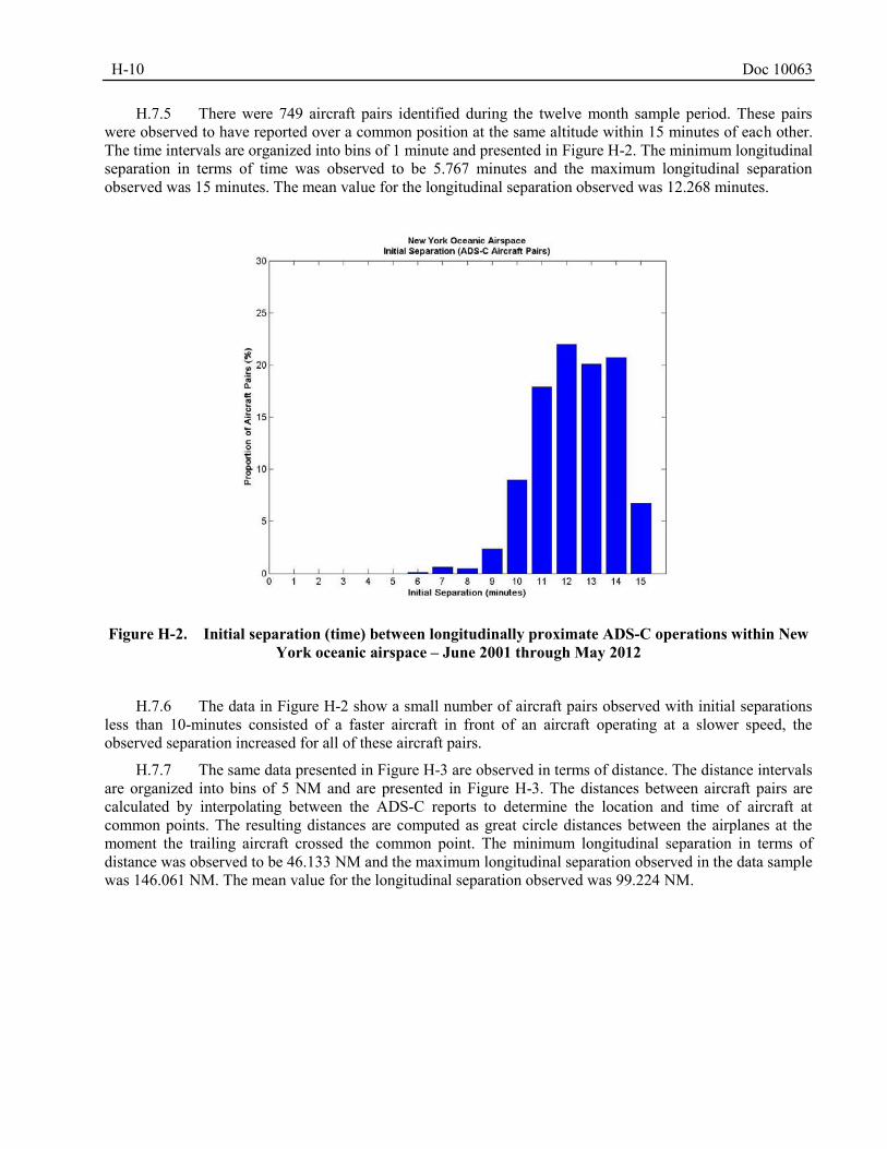
H-10 Doc 10063
H.7.5 There were 749 aircraft pairs identified during the twelve month sample period. These pairs were observed to have reported over a common position at the same altitude within 15 minutes of each other. The time intervals are organized into bins of 1 minute and presented in Figure H-2. The minimum longitudinal separation in terms of time was observed to be 5.767 minutes and the maximum longitudinal separation observed was 15 minutes. The mean value for the longitudinal separation observed was 12.268 minutes.
Figure H-2. Initial separation (time) between longitudinally proximate ADS-C operations within New
York oceanic airspace – June 2001 through May 2012
H.7.6 The data in Figure H-2 show a small number of aircraft pairs observed with initial separations less than 10-minutes consisted of a faster aircraft in front of an aircraft operating at a slower speed, the observed separation increased for all of these aircraft pairs.
H.7.7 The same data presented in Figure H-3 are observed in terms of distance. The distance intervals are organized into bins of 5 NM and are presented in Figure H-3. The distances between aircraft pairs are calculated by interpolating between the ADS-C reports to determine the location and time of aircraft at common points. The resulting distances are computed as great circle distances between the airplanes at the moment the trailing aircraft crossed the common point. The minimum longitudinal separation in terms of distance was observed to be 46.133 NM and the maximum longitudinal separation observed in the data sample was 146.061 NM. The mean value for the longitudinal separation observed was 99.224 NM.
Doc 10063 H-11
Figure H-3. Initial separation (distance) between longitudinally proximate ADS-C operations within
New York oceanic airspace – June 2001 through May 2012
H.7.8 The data in Figure H-3 show evidence of the application of the current 10-minute longitudinal separation minimum in New York oceanic airspace. Using an average ground speed of 480 knots, the application of the 10-minute longitudinal separation minimum is observed beginning with 80 NM in Figure H-3. The same observation noted from the data presented in Figure H-2 is also observed in Figure H-3. There are a small number of aircraft pairs with initial separation less than 80 NM. All of these aircraft pairs consisted of an aircraft operating at a faster speed than the following aircraft, the observed separation increased for all of these aircraft pairs.
H.7.9 Most of the 749 ADS-C aircraft pairs observed in the data sample were travelling in the east/west direction in the New York oceanic airspace. There were 403 and 335 aircraft pairs observed to be traveling in the east and west direction, respectively. There were nine and two aircraft pairs observed to be traveling in the north and south direction, respectively. This result is due to the imposed data sampling requirement that both aircraft use ADS-C for position reporting. The north/south traffic flows primarily consist of operations conducted on the WATRS routes, fewer WATRS operations currently utilize ADS-C and data link for ATC communication relative to NAT operations within New York oceanic airspace.
H.7.10 Of the 749 aircraft pairs identified during the time period June 2011 through May 2012, 69 aircraft pairs, or approximately 9 per cent of the observed aircraft pairs, would have been eligible for either the 30 NM or 50 NM longitudinal separation. Operations filing RNP 4 in the flight plan and using ADS-C/CPDLC for position reporting and communication with air traffic control are eligible for the 30 NM longitudinal separation standard.
H.7.11 The remaining 680 aircraft pairs, or approximately 91 per cent of the observed pairs during the twelve-month sample period, would have been eligible for the 50 NM longitudinal separation standard only. Both aircraft in the pair must be approved for RNP10 operations, file RNP 10 in the flight plan, and utilize ADS-C/CPDLC for position reporting and communication.
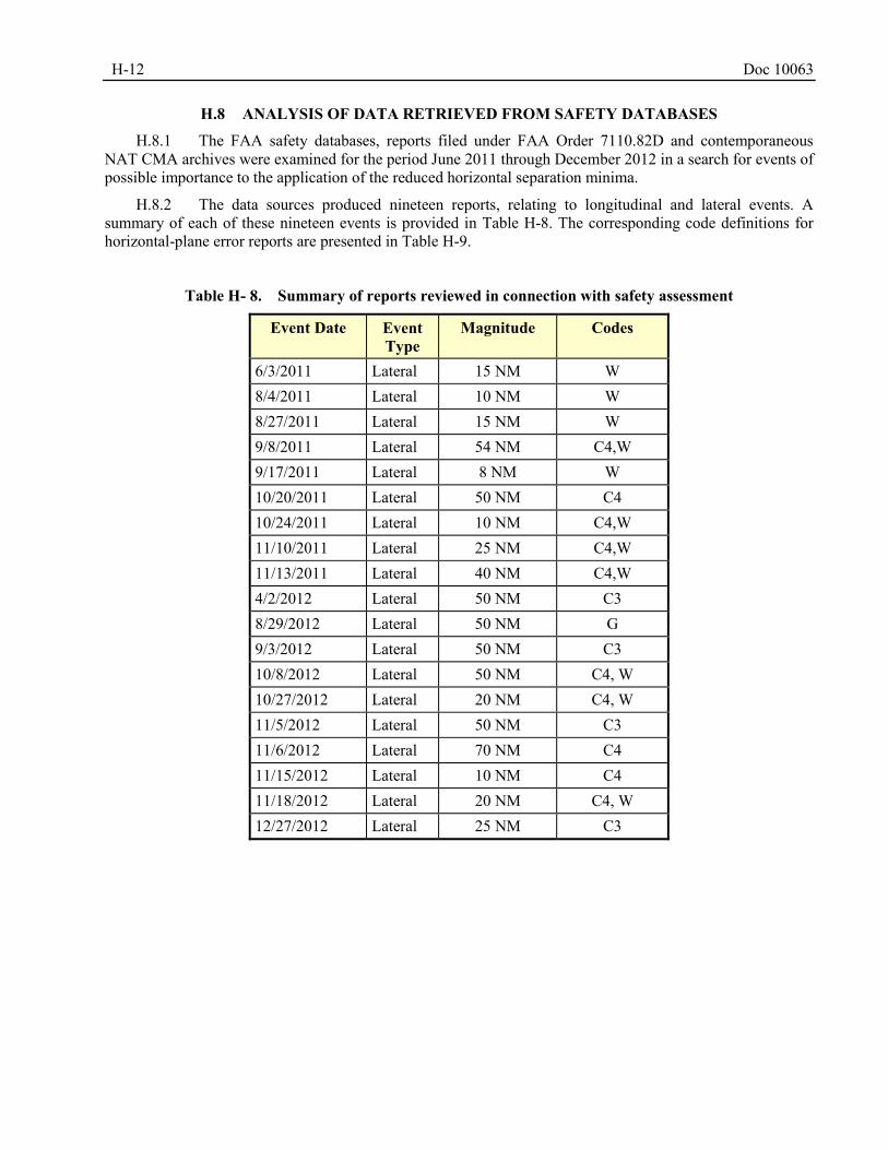
H-12 Doc 10063
ANALYSIS OF DATA RETRIEVED FROM SAFETY DATABASES H.8
H.8.1 The FAA safety databases, reports filed under FAA Order 7110.82D and contemporaneous NAT CMA archives were examined for the period June 2011 through December 2012 in a search for events of possible importance to the application of the reduced horizontal separation minima.
H.8.2 The data sources produced nineteen reports, relating to longitudinal and lateral events. A summary of each of these nineteen events is provided in Table H-8. The corresponding code definitions for horizontal-plane error reports are presented in Table H-9.
Table H- 8. Summary of reports reviewed in connection with safety assessment
Event Date Event Type
Magnitude Codes
6/3/2011 Lateral 15 NM W 8/4/2011 Lateral 10 NM W 8/27/2011 Lateral 15 NM W 9/8/2011 Lateral 54 NM C4,W 9/17/2011 Lateral 8 NM W 10/20/2011 Lateral 50 NM C4 10/24/2011 Lateral 10 NM C4,W 11/10/2011 Lateral 25 NM C4,W 11/13/2011 Lateral 40 NM C4,W 4/2/2012 Lateral 50 NM C3 8/29/2012 Lateral 50 NM G 9/3/2012 Lateral 50 NM C3 10/8/2012 Lateral 50 NM C4, W 10/27/2012 Lateral 20 NM C4, W 11/5/2012 Lateral 50 NM C3 11/6/2012 Lateral 70 NM C4 11/15/2012 Lateral 10 NM C4 11/18/2012 Lateral 20 NM C4, W 12/27/2012 Lateral 25 NM C3
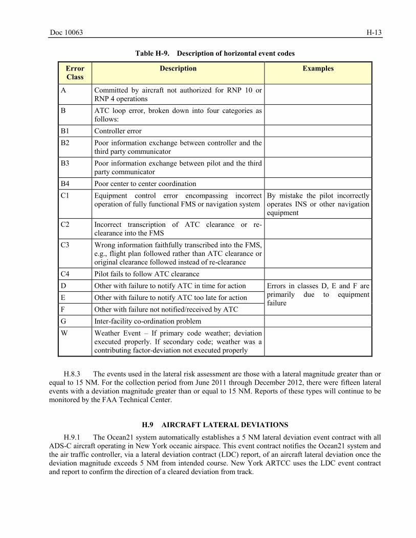
Doc 10063 H-13
Table H-9. Description of horizontal event codes
Error Class
Description Examples
A Committed by aircraft not authorized for RNP 10 or RNP 4 operations
B ATC loop error, broken down into four categories as follows:
B1 Controller error B2 Poor information exchange between controller and the
third party communicator
B3 Poor information exchange between pilot and the third party communicator
B4 Poor center to center coordination C1 Equipment control error encompassing incorrect
operation of fully functional FMS or navigation system By mistake the pilot incorrectly operates INS or other navigation equipment
C2 Incorrect transcription of ATC clearance or re-clearance into the FMS
C3 Wrong information faithfully transcribed into the FMS, e.g., flight plan followed rather than ATC clearance or original clearance followed instead of re-clearance
C4 Pilot fails to follow ATC clearance D Other with failure to notify ATC in time for action Errors in classes D, E and F are
primarily due to equipment failure
E Other with failure to notify ATC too late for action F Other with failure not notified/received by ATC G Inter-facility co-ordination problem W Weather Event – If primary code weather; deviation
executed properly. If secondary code; weather was a contributing factor-deviation not executed properly
H.8.3 The events used in the lateral risk assessment are those with a lateral magnitude greater than or equal to 15 NM. For the collection period from June 2011 through December 2012, there were fifteen lateral events with a deviation magnitude greater than or equal to 15 NM. Reports of these types will continue to be monitored by the FAA Technical Center.
AIRCRAFT LATERAL DEVIATIONS H.9
H.9.1 The Ocean21 system automatically establishes a 5 NM lateral deviation event contract with all ADS-C aircraft operating in New York oceanic airspace. This event contract notifies the Ocean21 system and the air traffic controller, via a lateral deviation contract (LDC) report, of an aircraft lateral deviation once the deviation magnitude exceeds 5 NM from intended course. New York ARTCC uses the LDC event contract and report to confirm the direction of a cleared deviation from track.
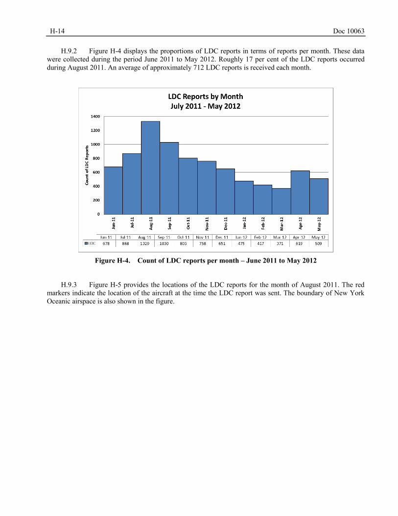
H-14 Doc 10063
H.9.2 Figure H-4 displays the proportions of LDC reports in terms of reports per month. These data were collected during the period June 2011 to May 2012. Roughly 17 per cent of the LDC reports occurred during August 2011. An average of approximately 712 LDC reports is received each month.
Figure H-4. Count of LDC reports per month – June 2011 to May 2012
H.9.3 Figure H-5 provides the locations of the LDC reports for the month of August 2011. The red markers indicate the location of the aircraft at the time the LDC report was sent. The boundary of New York Oceanic airspace is also shown in the figure.
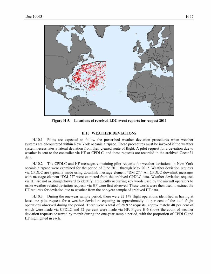
Doc 10063 H-15
Figure H-5. Locations of received LDC event reports for August 2011
WEATHER DEVIATIONS H.10
H.10.1 Pilots are expected to follow the prescribed weather deviation procedures when weather systems are encountered within New York oceanic airspace. These procedures must be invoked if the weather system necessitates a lateral deviation from their cleared route of flight. A pilot request for a deviation due to weather is sent to the controller via HF or CPDLC, and these requests are recorded in the archived Ocean21 data.
H.10.2 The CPDLC and HF messages containing pilot requests for weather deviations in New York oceanic airspace were examined for the period of June 2011 through May 2012. Weather deviation requests via CPDLC are typically made using downlink message element “DM 27.” All CPDLC downlink messages with message element “DM 27” were extracted from the archived CPDLC data. Weather deviation requests via HF are not as straightforward to identify. Frequently occurring key words used by the aircraft operators to make weather-related deviation requests via HF were first observed. These words were then used to extract the HF requests for deviation due to weather from the one-year sample of archived HF data.
H.10.3 During the one-year sample period, there were 22 149 flight operations identified as having at least one pilot request for a weather deviation, equating to approximately 11 per cent of the total flight operations observed during the period. There were a total of 28 972 requests, approximately 48 per cent of which were made via CPDLC and 52 per cent were made via HF. Figure H-6 shows the count of weather deviation requests observed by month during the one-year sample period, with the proportion of CPDLC and HF highlighted in each.
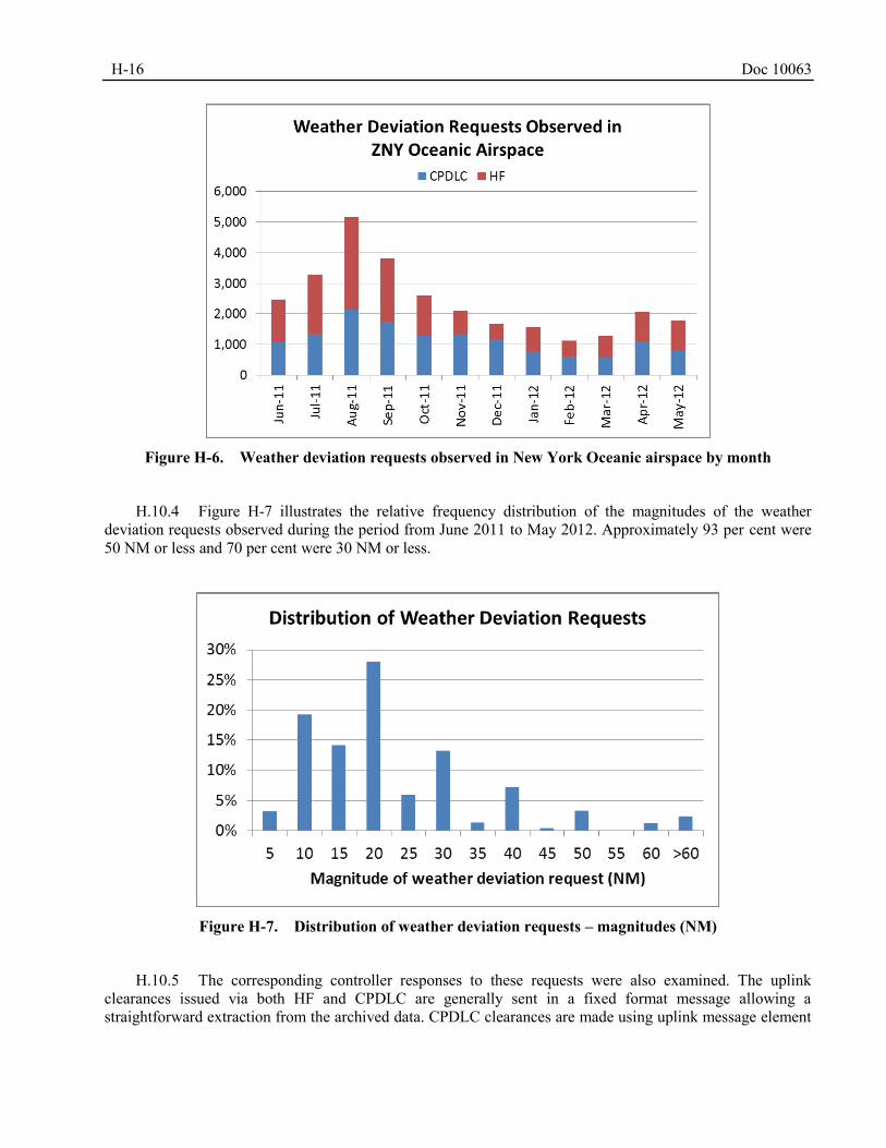
H-16 Doc 10063
Figure H-6. Weather deviation requests observed in New York Oceanic airspace by month
H.10.4 Figure H-7 illustrates the relative frequency distribution of the magnitudes of the weather deviation requests observed during the period from June 2011 to May 2012. Approximately 93 per cent were 50 NM or less and 70 per cent were 30 NM or less.
Figure H-7. Distribution of weather deviation requests – magnitudes (NM)
H.10.5 The corresponding controller responses to these requests were also examined. The uplink clearances issued via both HF and CPDLC are generally sent in a fixed format message allowing a straightforward extraction from the archived data. CPDLC clearances are made using uplink message element
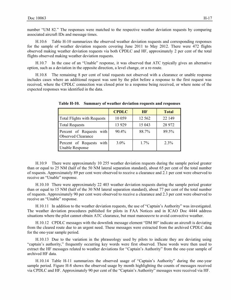
Doc 10063 H-17
number “UM 82.” The responses were matched to the respective weather deviation requests by comparing associated aircraft IDs and message times.
H.10.6 Table H-10 summarizes the observed weather deviation requests and corresponding responses for the sample of weather deviation requests covering June 2011 to May 2012. There were 472 flights observed making weather deviation requests via both CPDLC and HF, approximately 2 per cent of the total flights observed making weather deviation requests.
H.10.7 In the case of an “Unable” response, it was observed that ATC typically gives an alternative option, such as a deviation in the opposite direction, a level change, or a re-route.
H.10.8 The remaining 8 per cent of total requests not observed with a clearance or unable response includes cases where an additional request was sent by the pilot before a response to the first request was received, where the CPDLC connection was closed prior to a response being received, or where none of the expected responses was identified in the data.
Table H-10. Summary of weather deviation requests and responses
CPDLC HF Total Total Flights with Requests 10 059 12 562 22 149 Total Requests 13 929 15 043 28 972 Percent of Requests with Observed Clearance
90.4% 88.7% 89.5%
Percent of Requests with Unable Response
3.0% 1.7% 2.3%
H.10.9 There were approximately 10 255 weather deviation requests during the sample period greater than or equal to 25 NM (half of the 50 NM lateral separation standard), about 65 per cent of the total number of requests. Approximately 89 per cent were observed to receive a clearance and 2.1 per cent were observed to receive an “Unable” response.
H.10.10 There were approximately 22 403 weather deviation requests during the sample period greater than or equal to 15 NM (half of the 30 NM lateral separation standard), about 77 per cent of the total number of requests. Approximately 90 per cent were observed to receive a clearance and 2.3 per cent were observed to receive an “Unable” response.
H.10.11 In addition to the weather deviation requests, the use of “Captain’s Authority” was investigated. The weather deviation procedures published for pilots in FAA Notices and in ICAO Doc 4444 address situations where the pilot cannot obtain ATC clearance, but must manoeuvre to avoid convective weather.
H.10.12 CPDLC messages with the downlink message element “DM 80” indicate an aircraft is deviating from the cleared route due to an urgent need. These messages were extracted from the archived CPDLC data for the one-year sample period.
H.10.13 Due to the variation in the phraseology used by pilots to indicate they are deviating using “captain’s authority,” frequently occurring key words were first observed. These words were then used to extract the HF messages related to weather deviations for “Captain’s Authority” from the one-year sample of archived HF data.
H.10.14 Table H-11 summarizes the observed usage of “Captain’s Authority” during the one-year sample period. Figure H-8 shows the observed usage by month highlighting the counts of messages received via CPDLC and HF. Approximately 90 per cent of the “Captain’s Authority” messages were received via HF.
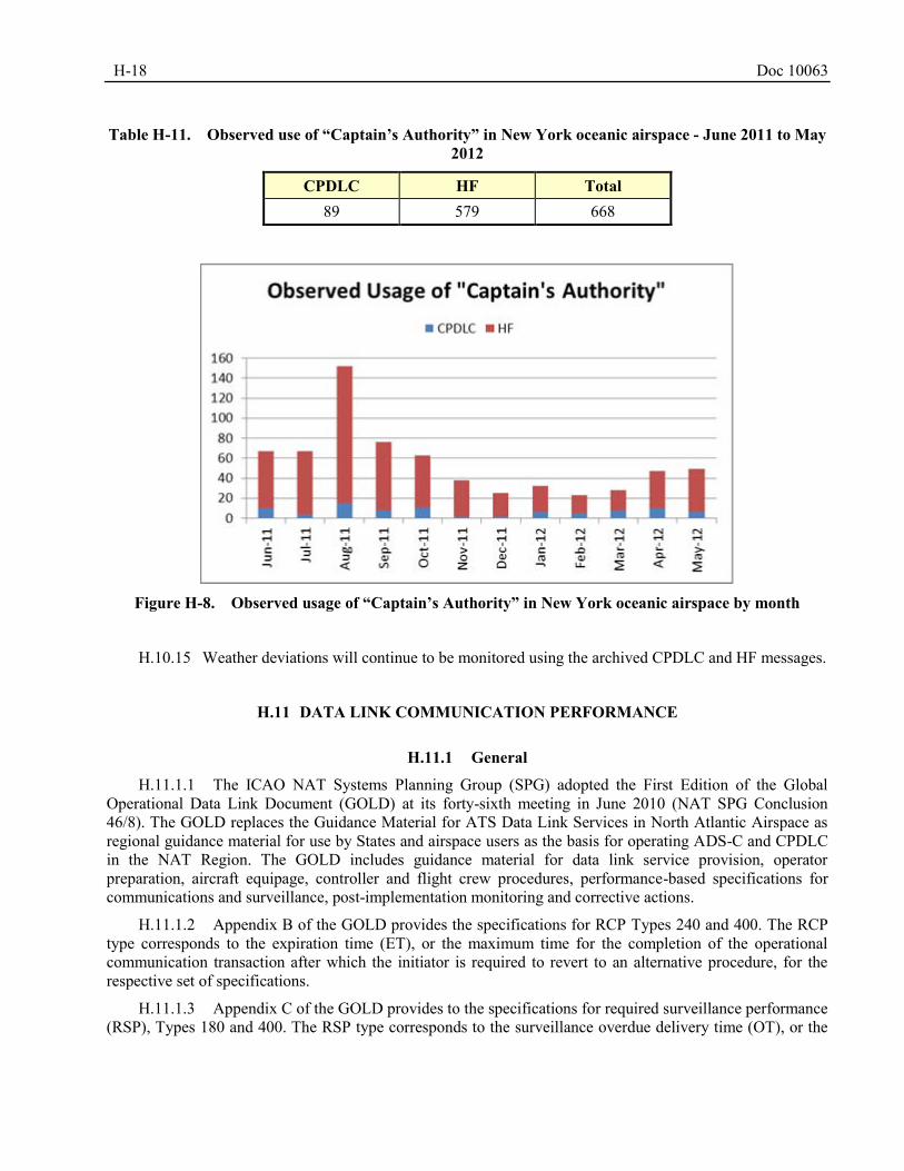
H-18 Doc 10063
Table H-11. Observed use of “Captain’s Authority” in New York oceanic airspace - June 2011 to May
2012
CPDLC HF Total 89 579 668
Figure H-8. Observed usage of “Captain’s Authority” in New York oceanic airspace by month
H.10.15 Weather deviations will continue to be monitored using the archived CPDLC and HF messages.
DATA LINK COMMUNICATION PERFORMANCE H.11
H.11.1 General
H.11.1.1 The ICAO NAT Systems Planning Group (SPG) adopted the First Edition of the Global Operational Data Link Document (GOLD) at its forty-sixth meeting in June 2010 (NAT SPG Conclusion 46/8). The GOLD replaces the Guidance Material for ATS Data Link Services in North Atlantic Airspace as regional guidance material for use by States and airspace users as the basis for operating ADS-C and CPDLC in the NAT Region. The GOLD includes guidance material for data link service provision, operator preparation, aircraft equipage, controller and flight crew procedures, performance-based specifications for communications and surveillance, post-implementation monitoring and corrective actions.
H.11.1.2 Appendix B of the GOLD provides the specifications for RCP Types 240 and 400. The RCP type corresponds to the expiration time (ET), or the maximum time for the completion of the operational communication transaction after which the initiator is required to revert to an alternative procedure, for the respective set of specifications.
H.11.1.3 Appendix C of the GOLD provides to the specifications for required surveillance performance (RSP), Types 180 and 400. The RSP type corresponds to the surveillance overdue delivery time (OT), or the
Doc 10063 H-19
maximum time for the successful delivery of surveillance data after which the initiator is required to revert to an alternative procedure, for the respective set of specifications.
H.11.1.4 The RCP/RSP specifications are derived mainly from safety assessment, but where appropriate they include criteria to support operational efficiency and orderly flow of air traffic. In these cases, the specification indicates the distinction between safety and efficiency. In general these specifications provide a means of compliance and support:
a) safety oversight of ATS provisions and operations;
b) agreements/contractual arrangements that ATS providers and aircraft operators make with respective CSPs;
c) operational authorizations, flight crew training and qualification;
d) design approval of aircraft data link systems; and
e) operational monitoring, analysis, and exchange of operational data among regions and States.
H.11.1.5 The RCP and RSP specifications are comprised of four elements: time, continuity, availability and integrity. Within the specifications for each element there are allocations for each of the four main data link system components: air traffic service provider (ATSP), communication service provider (CSP), aircraft system and aircraft operator.
H.11.2 Data link time and continuity
H.11.2.1 ICAO Doc 9869 now contains the information previously covered in Appendix D of the GOLD; it provides guidance for post-implementation monitoring of the data link system according to the RCP/RSP specifications. It details the data points that are necessary to extract from the FANS 1/A aircraft communications addressing and reporting system (ACARS) messages to calculate the performance measures: actual communication performance (ACP), actual communication technical performance (ACTP), pilot operational response time (PORT), and ADS-C downlink latency; and to conduct the prescribed analysis.
H.11.2.2 The ADS-C downlink latency is assessed for all ADS-C downlink messages when monitoring RSP; however, a specific subset of CPDLC transactions is considered when monitoring RCP. Only uplink communications transfer messages and typical intervention messages such as climb clearances with a WILCO response are assessed. These messages are considered to be intervention messages critical to the communications used when applying reduced separation standards.
H.11.2.3 According to the guidance in the GOLD, the ACP, ACTP and PORT for applicable CPDLC transactions are required to meet the RCP 240 criteria when sent via satellite and VHF; and are required to meet RCP 400 criteria when sent via HF. Similarly, the ADS-C downlink latency is required to meet RSP 180 criteria for ADS-C downlink messages sent via satellite and VHF; and is required to meet RSP 400 criteria when sent via HF.
H.11.2.4 Table H-12 summarizes the RCP 240 and RSP 180 specifications applicable for the application of the 50 NM longitudinal, 30 NM lateral and 30 NM longitudinal separation minima. The performance criteria associated with each prescribed performance measure are listed.
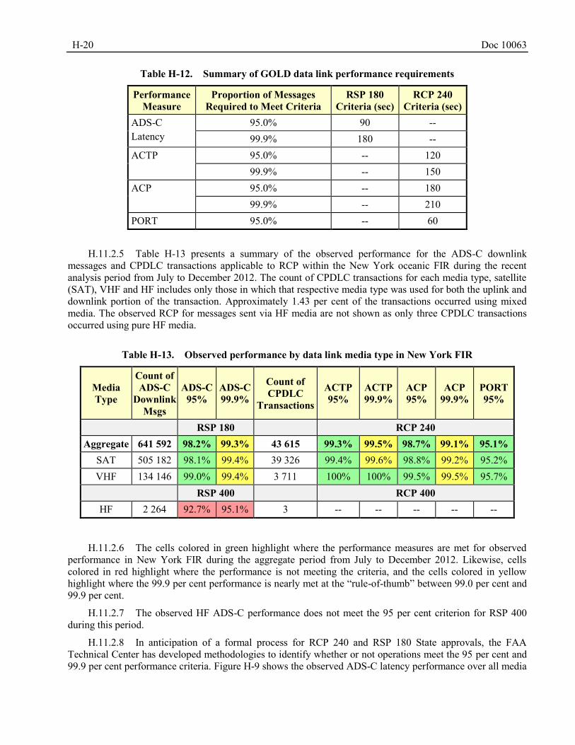
H-20 Doc 10063
Table H-12. Summary of GOLD data link performance requirements
Performance Measure
Proportion of Messages Required to Meet Criteria
RSP 180 Criteria (sec)
RCP 240 Criteria (sec)
ADS-C Latency
95.0% 90 -- 99.9% 180 --
ACTP 95.0% -- 120 99.9% -- 150
ACP 95.0% -- 180 99.9% -- 210
PORT 95.0% -- 60
H.11.2.5 Table H-13 presents a summary of the observed performance for the ADS-C downlink messages and CPDLC transactions applicable to RCP within the New York oceanic FIR during the recent analysis period from July to December 2012. The count of CPDLC transactions for each media type, satellite (SAT), VHF and HF includes only those in which that respective media type was used for both the uplink and downlink portion of the transaction. Approximately 1.43 per cent of the transactions occurred using mixed media. The observed RCP for messages sent via HF media are not shown as only three CPDLC transactions occurred using pure HF media.
Table H-13. Observed performance by data link media type in New York FIR
Media Type
Count of ADS-C
Downlink Msgs
ADS-C 95%
ADS-C 99.9%
Count of CPDLC
Transactions
ACTP 95%
ACTP 99.9%
ACP 95%
ACP 99.9%
PORT 95%
RSP 180 RCP 240 Aggregate 641 592 98.2% 99.3% 43 615 99.3% 99.5% 98.7% 99.1% 95.1%
SAT 505 182 98.1% 99.4% 39 326 99.4% 99.6% 98.8% 99.2% 95.2% VHF 134 146 99.0% 99.4% 3 711 100% 100% 99.5% 99.5% 95.7%
RSP 400 RCP 400 HF 2 264 92.7% 95.1% 3 -- -- -- -- --
H.11.2.6 The cells colored in green highlight where the performance measures are met for observed performance in New York FIR during the aggregate period from July to December 2012. Likewise, cells colored in red highlight where the performance is not meeting the criteria, and the cells colored in yellow highlight where the 99.9 per cent performance is nearly met at the “rule-of-thumb” between 99.0 per cent and 99.9 per cent.
H.11.2.7 The observed HF ADS-C performance does not meet the 95 per cent criterion for RSP 400 during this period.
H.11.2.8 In anticipation of a formal process for RCP 240 and RSP 180 State approvals, the FAA Technical Center has developed methodologies to identify whether or not operations meet the 95 per cent and 99.9 per cent performance criteria. Figure H-9 shows the observed ADS-C latency performance over all media
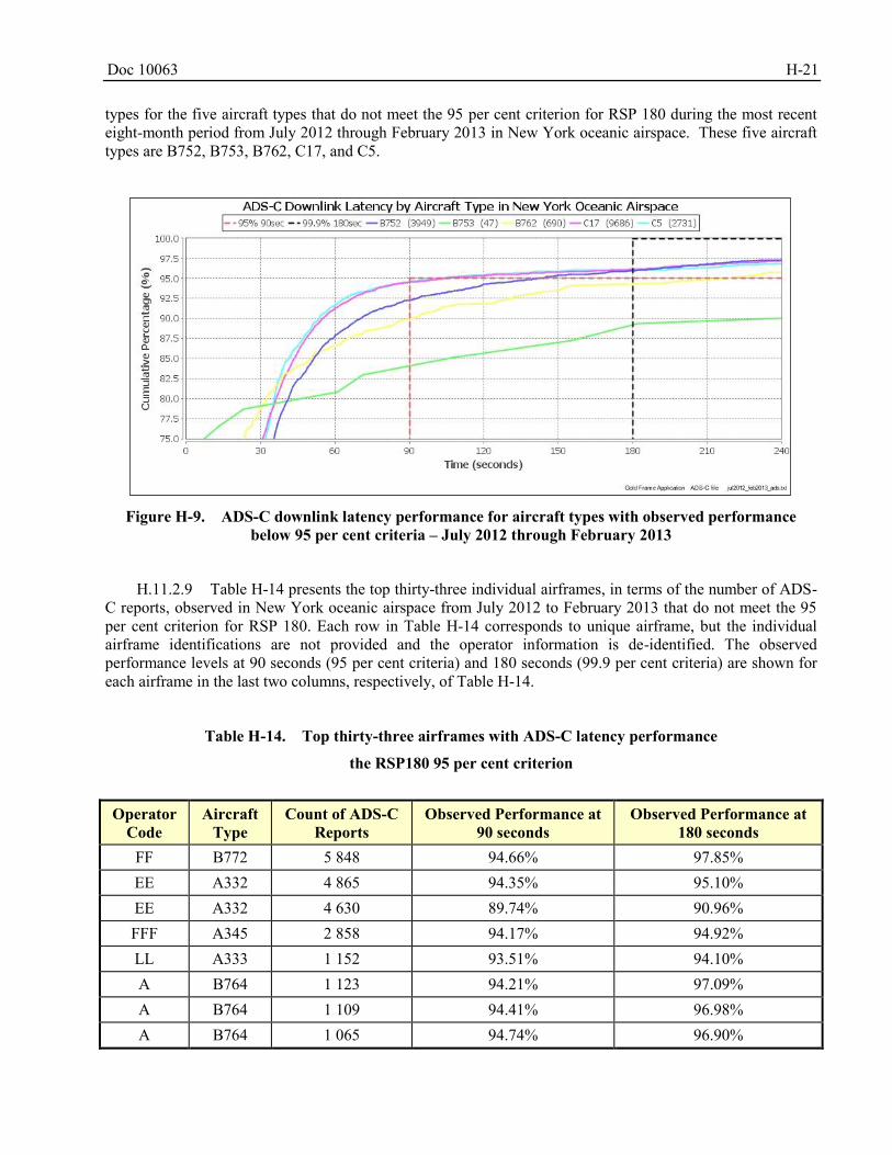
Doc 10063 H-21
types for the five aircraft types that do not meet the 95 per cent criterion for RSP 180 during the most recent eight-month period from July 2012 through February 2013 in New York oceanic airspace. These five aircraft types are B752, B753, B762, C17, and C5.
Figure H-9. ADS-C downlink latency performance for aircraft types with observed performance
below 95 per cent criteria – July 2012 through February 2013
H.11.2.9 Table H-14 presents the top thirty-three individual airframes, in terms of the number of ADS-C reports, observed in New York oceanic airspace from July 2012 to February 2013 that do not meet the 95 per cent criterion for RSP 180. Each row in Table H-14 corresponds to unique airframe, but the individual airframe identifications are not provided and the operator information is de-identified. The observed performance levels at 90 seconds (95 per cent criteria) and 180 seconds (99.9 per cent criteria) are shown for each airframe in the last two columns, respectively, of Table H-14.
Table H-14. Top thirty-three airframes with ADS-C latency performance
the RSP180 95 per cent criterion
Operator
Code Aircraft
Type Count of ADS-C
Reports Observed Performance at
90 seconds Observed Performance at
180 seconds FF B772 5 848 94.66% 97.85% EE A332 4 865 94.35% 95.10% EE A332 4 630 89.74% 90.96% FFF A345 2 858 94.17% 94.92% LL A333 1 152 93.51% 94.10% A B764 1 123 94.21% 97.09% A B764 1 109 94.41% 96.98% A B764 1 065 94.74% 96.90%
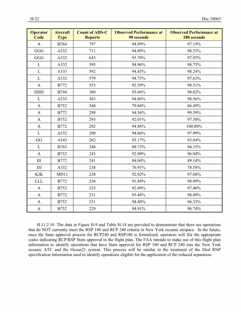
H-22 Doc 10063
Operator Code
Aircraft Type
Count of ADS-C Reports
Observed Performance at 90 seconds
Observed Performance at 180 seconds
A B764 797 94.89% 97.19% GGG A332 711 94.89% 98.53% GGG A332 643 93.70% 97.93%
L A332 595 94.96% 98.75% L A333 592 94.43% 98.24% L A332 579 94.73% 97.63% A B772 553 92.59% 98.31%
HHH B744 380 93.68% 98.02% L A333 363 94.86% 98.56% A B752 348 79.84% 86.49% A B772 298 94.56% 99.59% A B752 293 92.01% 97.50% A B772 292 94.86% 100.00% L A332 290 94.66% 97.99%
GG A343 262 93.17% 93.84% L B763 248 89.73% 94.35% A B752 243 92.90% 96.94% III B772 241 88.04% 89.14% JJJ A332 238 76.91% 78.58%
KJK MD11 238 92.02% 97.68% LLL B772 236 91.84% 98.49%
A B752 233 92.49% 97.46% A B772 231 93.44% 98.89% A B752 231 94.40% 96.33% A B752 229 94.91% 96.74%
H.11.2.10 The data in Figure H-9 and Table H-14 are provided to demonstrate that there are operations that do NOT currently meet the RSP 180 and RCP 240 criteria in New York oceanic airspace. In the future, once the State approval process for RCP240 and RSP180 is formalized, operators will file the appropriate codes indicating RCP/RSP State approval in the flight plan. The FAA intends to make use of this flight plan information to identify operations that have State approval for RSP 180 and RCP 240 into the New York oceanic ATC and the Ocean21 system. This process will be similar to the treatment of the filed RNP specification information used to identify operations eligible for the application of the reduced separation.
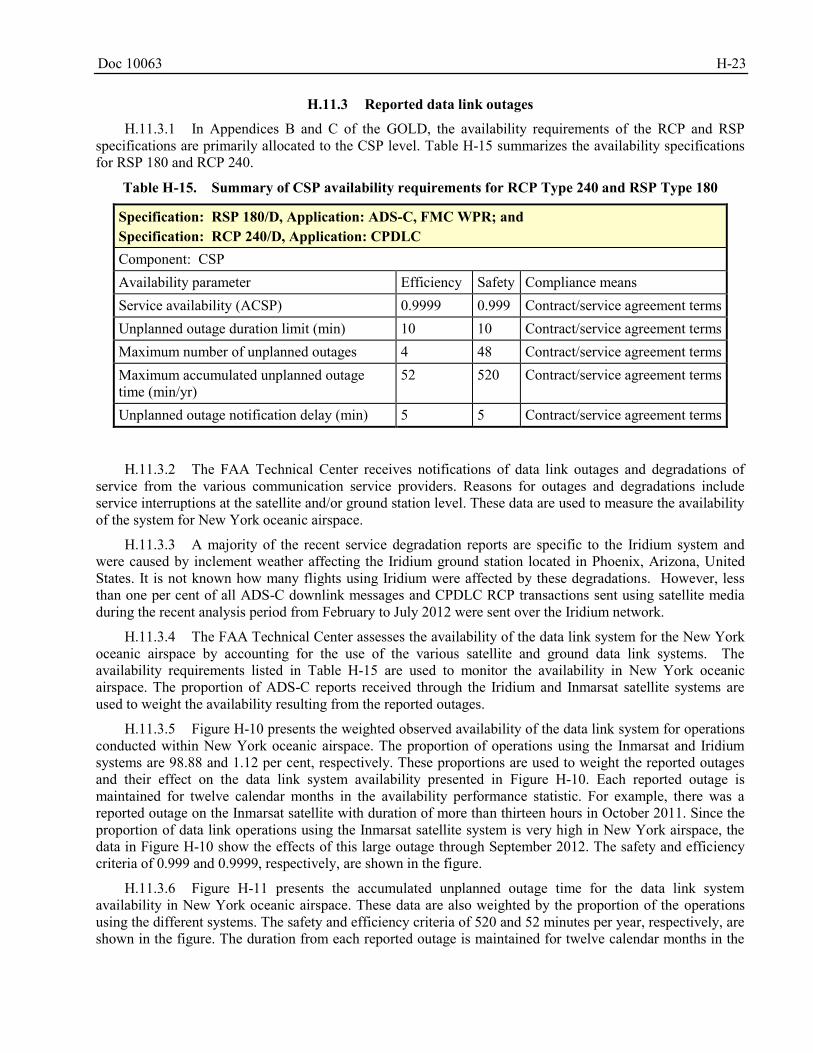
Doc 10063 H-23
H.11.3 Reported data link outages
H.11.3.1 In Appendices B and C of the GOLD, the availability requirements of the RCP and RSP specifications are primarily allocated to the CSP level. Table H-15 summarizes the availability specifications for RSP 180 and RCP 240.
Table H-15. Summary of CSP availability requirements for RCP Type 240 and RSP Type 180
Specification: RSP 180/D, Application: ADS-C, FMC WPR; and Specification: RCP 240/D, Application: CPDLC Component: CSP Availability parameter Efficiency Safety Compliance means Service availability (ACSP) 0.9999 0.999 Contract/service agreement terms Unplanned outage duration limit (min) 10 10 Contract/service agreement terms Maximum number of unplanned outages 4 48 Contract/service agreement terms Maximum accumulated unplanned outage time (min/yr)
52 520 Contract/service agreement terms
Unplanned outage notification delay (min) 5 5 Contract/service agreement terms
H.11.3.2 The FAA Technical Center receives notifications of data link outages and degradations of service from the various communication service providers. Reasons for outages and degradations include service interruptions at the satellite and/or ground station level. These data are used to measure the availability of the system for New York oceanic airspace.
H.11.3.3 A majority of the recent service degradation reports are specific to the Iridium system and were caused by inclement weather affecting the Iridium ground station located in Phoenix, Arizona, United States. It is not known how many flights using Iridium were affected by these degradations. However, less than one per cent of all ADS-C downlink messages and CPDLC RCP transactions sent using satellite media during the recent analysis period from February to July 2012 were sent over the Iridium network.
H.11.3.4 The FAA Technical Center assesses the availability of the data link system for the New York oceanic airspace by accounting for the use of the various satellite and ground data link systems. The availability requirements listed in Table H-15 are used to monitor the availability in New York oceanic airspace. The proportion of ADS-C reports received through the Iridium and Inmarsat satellite systems are used to weight the availability resulting from the reported outages.
H.11.3.5 Figure H-10 presents the weighted observed availability of the data link system for operations conducted within New York oceanic airspace. The proportion of operations using the Inmarsat and Iridium systems are 98.88 and 1.12 per cent, respectively. These proportions are used to weight the reported outages and their effect on the data link system availability presented in Figure H-10. Each reported outage is maintained for twelve calendar months in the availability performance statistic. For example, there was a reported outage on the Inmarsat satellite with duration of more than thirteen hours in October 2011. Since the proportion of data link operations using the Inmarsat satellite system is very high in New York airspace, the data in Figure H-10 show the effects of this large outage through September 2012. The safety and efficiency criteria of 0.999 and 0.9999, respectively, are shown in the figure.
H.11.3.6 Figure H-11 presents the accumulated unplanned outage time for the data link system availability in New York oceanic airspace. These data are also weighted by the proportion of the operations using the different systems. The safety and efficiency criteria of 520 and 52 minutes per year, respectively, are shown in the figure. The duration from each reported outage is maintained for twelve calendar months in the
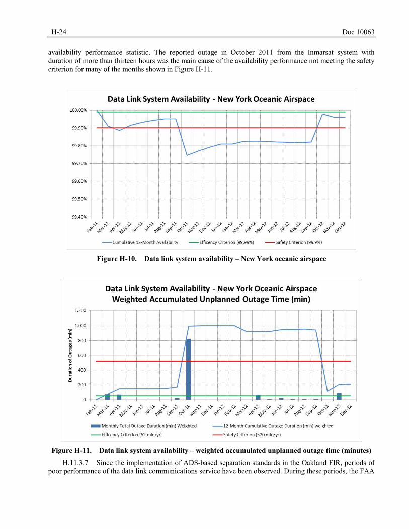
H-24 Doc 10063
availability performance statistic. The reported outage in October 2011 from the Inmarsat system with duration of more than thirteen hours was the main cause of the availability performance not meeting the safety criterion for many of the months shown in Figure H-11.
Figure H-10. Data link system availability – New York oceanic airspace
Figure H-11. Data link system availability – weighted accumulated unplanned outage time (minutes)
H.11.3.7 Since the implementation of ADS-based separation standards in the Oakland FIR, periods of poor performance of the data link communications service have been observed. During these periods, the FAA
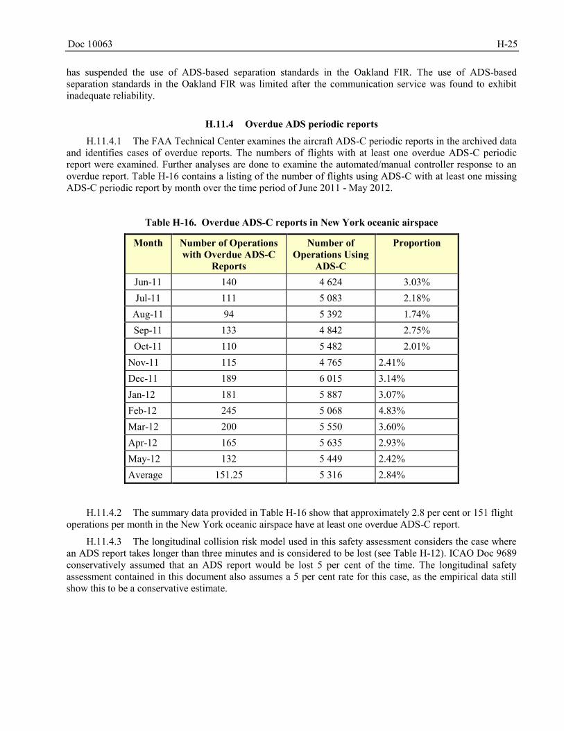
Doc 10063 H-25
has suspended the use of ADS-based separation standards in the Oakland FIR. The use of ADS-based separation standards in the Oakland FIR was limited after the communication service was found to exhibit inadequate reliability.
H.11.4 Overdue ADS periodic reports
H.11.4.1 The FAA Technical Center examines the aircraft ADS-C periodic reports in the archived data and identifies cases of overdue reports. The numbers of flights with at least one overdue ADS-C periodic report were examined. Further analyses are done to examine the automated/manual controller response to an overdue report. Table H-16 contains a listing of the number of flights using ADS-C with at least one missing ADS-C periodic report by month over the time period of June 2011 - May 2012.
Table H-16. Overdue ADS-C reports in New York oceanic airspace
Month Number of Operations with Overdue ADS-C
Reports
Number of Operations Using
ADS-C
Proportion
Jun-11 140 4 624 3.03% Jul-11 111 5 083 2.18%
Aug-11 94 5 392 1.74% Sep-11 133 4 842 2.75% Oct-11 110 5 482 2.01%
Nov-11 115 4 765 2.41% Dec-11 189 6 015 3.14% Jan-12 181 5 887 3.07% Feb-12 245 5 068 4.83% Mar-12 200 5 550 3.60% Apr-12 165 5 635 2.93% May-12 132 5 449 2.42% Average 151.25 5 316 2.84%
H.11.4.2 The summary data provided in Table H-16 show that approximately 2.8 per cent or 151 flight operations per month in the New York oceanic airspace have at least one overdue ADS-C report.
H.11.4.3 The longitudinal collision risk model used in this safety assessment considers the case where an ADS report takes longer than three minutes and is considered to be lost (see Table H-12). ICAO Doc 9689 conservatively assumed that an ADS report would be lost 5 per cent of the time. The longitudinal safety assessment contained in this document also assumes a 5 per cent rate for this case, as the empirical data still show this to be a conservative estimate.
H-26 Doc 10063
OCEAN21 DECISION-SUPPORT FEATURES IMPORTANT TO THE APPLICATION OF H.12
THE REDUCED HORIZONTAL SEPARATION STANDARDS
H.12.1 The Ocean21 system provides many enhancements to the application of ATC in New York oceanic airspace. Several of these are particularly important to use for the 50 NM longitudinal, 30 NM lateral and 30 NM longitudinal separation minima. It is not possible to separate the effect of the ATC automation and decision support tools from the data. Therefore, it can be concluded that the Ocean21 system (or similar functioning system) must also be present when applying the reduced separation minimum.
Ocean21 System Display
H.12.2 The system aids controller situational awareness and decision making using a full-color display which provides important descriptive data for each aircraft, including indications of separation minima which may be approved for eligible pairs of aircraft. The display presents the full geographic extent of the controller’s area of responsibility, as well as adjacent areas.
Ocean21 Conflict Probe
H.12.3 Upon receipt of an ADS-C report from an aircraft or controller request for examination of a modification to an aircraft’s current flight plan, the system automatically looks for conflicts between aircraft trajectories, or violations of applicable separation minima, between the aircraft and all others in the airspace, using a preset interval look-ahead time. If a conflict is uncovered, the controller is notified on the Ocean21 display by means of flashing colored leader lines from the two aircraft in conflict, with intersection of the lines at the projected point of conflict. The probe is informed not only by previously received ADS position reports from all aircraft under ATC, but also by meteorological forecasts which are updated appropriately to the latest version received at the New York ARTCC.
PARAMETERS FOR THE COLLISION RISK MODELS H.13
H.13.1 General
H.13.1.1 Several of the collision risk parameters are common to both the lateral and longitudinal collision risk models, provided in equations 1 and 2, respectively. The next sections provide the values of each parameter needed to estimate the collision risk associated with the reduced horizontal separation standards.
H.13.2 Parameters common to the lateral and longitudinal collision risk models
H.13.2.1 Aircraft length, wingspan and height - x,
y and
z
H.13.2.1.1 The length, wingspan and height of the average aircraft observed in New York oceanic airspace are obtained from the aircraft types contained in the KYA study. The length, wingspan, and height of the average aircraft are calculated using a weighted average based on the proportion of aircraft types observed in the airspace. Table H-17 shows the aircraft length, wingspan and height, expressed in NM, of the aircraft types observed in the airspace. The weighted average aircraft length, wingspan, and height, expressed in NM, are 0.03087, 0.002826 and 0.00876, respectively.
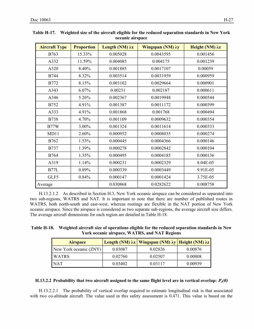
Doc 10063 H-27
Table H-17. Weighted size of the aircraft eligible for the reduced separation standards in New York
oceanic airspace
Aircraft Type Proportion Length (NM) λx Wingspan (NM) λy Height (NM) λz B763 15.33% 0.005028 0.0043595 0.001456 A332 11.59% 0.004085 0.004175 0.001239 A320 8.40% 0.001885 0.0017107 0.00059 B744 8.32% 0.003514 0.0031959 0.000959 B772 8.15% 0.003102 0.0029664 0.000901 A343 6.07% 0.00231 0.002187 0.000611 A346 5.26% 0.002367 0.0019948 0.000544 B752 4.91% 0.001387 0.0011172 0.000399 A333 4.91% 0.001868 0.001768 0.000494 B738 4.70% 0.001109 0.0009632 0.000354 B77W 3.00% 0.001324 0.0011614 0.000333 MD11 2.60% 0.000952 0.0008035 0.000274 B762 1.53% 0.000445 0.0004366 0.000146 B737 1.39% 0.000278 0.0002842 0.000104 B764 1.35% 0.000495 0.0004185 0.000136 A319 1.14% 0.000231 0.0002329 8.04E-05 B77L 0.89% 0.000339 0.0003449 9.91E-05 GLF5 0.84% 0.000147 0.0001424 3.75E-05
Average 0.030868 0.0282622 0.008758
H.13.2.1.2 As described in Section H.3, New York oceanic airspace can be considered as separated into two sub-regions, WATRS and NAT. It is important to note that there are number of published routes in WATRS, both north-south and east-west, whereas routings are flexible in the NAT portion of New York oceanic airspace. Since the airspace is considered as two separate sub-regions, the average aircraft size differs. The average aircraft dimensions for each region are detailed in Table H-18.
Table H-18. Weighted aircraft size of operations eligible for the reduced separation standards in New
York oceanic airspace, WATRS, and NAT Regions
Airspace Length (NM) λx Wingspan (NM) λy Height (NM) λz New York oceanic (ZNY) 0.03087 0.02826 0.00876 WATRS 0.02760 0.02507 0.00808 NAT 0.03402 0.03117 0.00939
H.13.2.2 Probability that two aircraft assigned to the same flight level are in vertical overlap: Pz(0)
H.13.2.2.1 The probability of vertical overlap required to estimate longitudinal risk is that associated with two co-altitude aircraft. The value used in this safety assessment is 0.471. This value is based on the
H-28 Doc 10063
current value used for NAT airspace, 0.48, but is adjusted for the difference in the average aircraft heights (0.00876/0.00892).
H.13.2.3 The average relative vertical speed of two aircraft assigned to the same flight level: z
H.13.2.3.1 As has been the case in all recent safety assessments conducted to support separation changes in the Pacific and North Atlantic, the value used in this document is 1.5 knots. This value also reflects the effect of the RVSM on height-keeping performance.
H.13.3 Parameters used only in estimation of lateral risk
H.13.3.1 Average absolute relative along-track speed of two-aircraft as they pass on parallel
tracks - x
H.13.3.1.1 Aircraft operations on parallel tracks are independent of application of Mach number technique or any other actions by ATC to regulate the relative speed between aircraft. As a result, the relative speed between a typical pair of co-altitude aircraft on adjacent tracks reflects the range of speeds of individual aircraft in the airspace. The FAA Technical Center assembled the reported ground speeds, obtained from the ADS-C basic reports, from 298 669 ADS-C operations in New York oceanic airspace over the period January through May 2012.
H.13.3.1.2 Using the uncorrelated-speed property of aircraft assigned to the same flight level on parallel routes, the absolute value of each possible difference in speed are weighted according to the proportions of entries. These weighted speed differences are averaged, producing a value of 27 knots for the average relative along-track speed of a pair of co-altitude on laterally adjacent routes.
H.13.3.2 Average absolute relative cross-track speed between aircraft pairs operating on tracks
nominally separated by Sy - )( ySy
H.13.3.2.1 This parameter describes the relative speed of two aircraft as they lose all planned lateral separation. Since the basic track-keeping accuracy of aircraft equipped with navigation systems using GNSS-derived positioning is widely regarded as precluding the loss of 30 NM lateral separation due to normal navigational performance, the most reasonable circumstance associated with an event is a waypoint insertion error. While there are Ocean21 safeguards against the occurrence of this type of event - conflict probe examination of filed flight plan and establishment of a 5 NM lateral deviation event contract for all aircraft capable of participating in the application of the 30 NM separation minima – the estimation of the lateral risk proceeds with a value of 36 knots for the relative across-track speed parameter. This value corresponds to the lateral speed of an aircraft relative to correct track, which would result in a lateral error of 30 NM between two waypoints separated by a typical distance in New York oceanic airspace. The assumed average aircraft speed used was 480 knots, and the typical distance between two consecutive waypoints in New York oceanic airspace was 400 NM.
H.13.3.3 Same and opposite direction lateral occupancies – Ey(same) and E
y(opp)
H.13.3.3.1 Occupancy is a measure of exposure of aircraft to one another within an airspace. While occupancy does generally increase as traffic level increases, there is not a one-to-one correspondence between a measure of traffic activity – number of annual flights, for example – and the value of airspace occupancy.
Doc 10063 H-29
Rather, occupancy increases as more aircraft operate at the same time on the laterally adjacent flight paths, increasing the chance that there might be a proximate aircraft.
H.13.3.3.2 Occupancy is a dimensionless number, computed, in the lateral case, as twice the ratio of the number of aircraft on a track which are within an arbitrary longitudinal sampling interval of a typical aircraft on a laterally adjacent track. Lateral occupancy is estimated separately for aircraft flows operating in the same direction on each of two parallel tracks and for flows operating on reciprocal headings on the tracks – hence the terms “same direction” and “opposite direction” lateral occupancies.
H.13.3.3.3 The product of the ratio (2λx/Sx) and E
y(same) is twice the probability of longitudinal
overlap, Px, for co-altitude same direction aircraft pairs on parallel routes; the same ratio multiplied by Ey(opp) produces the comparable opposite direction probability.
H.13.3.3.4 The same and opposite direction lateral occupancy values were estimated from a six-month sample of Ocean21 data including May, July, September and November 2011 and January and March 2012. A lateral pair was identified for an aircraft when a second aircraft crossed over the adjacent airway fix located on a parallel route separated laterally by 50 NM, at the same flight level within fifteen minutes of the first aircraft. The same and opposite direction lateral occupancy values used in the safety assessment are 0.0641 and 0.0005, respectively.
H.13.3.4 Probability that two aircraft lose planned 30 NM lateral separation – Py(30)
H.13.3.4.1 The RNP 4 is the required lateral navigation performance for the application of the 30 NM lateral separation standard. The navigation performance and the reports of gross lateral errors are combined to estimate the lateral overlap probability.
H.13.3.4.2 In the past, aircraft lateral deviations have been modeled as Double-Double Exponential (DDE) random variables. A probability density function for the DDE distribution is given in Eq. (4) as:
21
2121
22
1,,;
xx
eexf
where 0 < α < 1, and 0 < λ1 < λ2 (4)
H.13.3.4.3 The DDE density is a weighted sum of two double exponential densities, one often called the “core” density, and the other known as the “tail” density. The weights are 1-α and α; the core density,
1
12
1
x
e
, describes typical lateral deviations from the centerline of the aircraft’s intended route; and the tail
density, 2
22
1
x
e
, describes atypical lateral deviations from the centerline of the intended route.
H.13.3.4.4 The core density is determined by 4-NM / 95 per cent containment. The parameter λ1 representing the typical lateral errors can be estimated directly from the RNP value for the airspace. In this case, λ1 is estimated to be 1.335 NM.
H.13.3.4.5 The tail density is determined by the frequency of the atypical lateral errors reported in the airspace. It has been shown using principles of differential calculus that the overlap probability can be approximately maximized by selecting a λ2 equal to the designated separation minimum, in this case 30 NM. The contribution of the tail density is determined by α. The frequency of lateral errors described in Section H.8 gives the value for α as 7.38 x 10⁻⁵.
H-30 Doc 10063
H.13.3.4.6 The probability of lateral overlap is determined by self-convolving the density given in (4) with the parameter estimates given above. The resulting value for the probability of lateral overlap used in this safety assessment is 5.13 x 10⁻⁸.
H.13.3.4.7 Table H-19 provides a listing of the lateral collision risk model parameter values used in the safety assessment for the implementation of the 30 NM lateral separation standard in New York oceanic airspace.
Table H-19. Parameter values for the lateral collision risk model for the 30 NM lateral separation
standard in New York oceanic airspace
Parameter Symbol Parameter Definition Parameter Value Source for Value
x Average absolute relative along track speed between aircraft on same direction routes
27 knots Estimated from ADS-C reports in traffic sample
Average absolute aircraft air speed
480 knots
)30(y Average absolute relative cross track speed
36 knots
Average absolute relative vertical speed of an aircraft pair that have lost all vertical separation
1.5 knots
Sx Length of longitudinal
window used to calculate occupancy
120 NM
x Average aircraft length 0.0309 NM Weighted average based on traffic sample
y Average aircraft wing-span
0.0283 NM Weighted average based on traffic sample
z Average aircraft height with undercarriage retracted
0.0088 NM Weighted average based on traffic sample
0Pz Probability that two aircraft which are nominally at the same level are in vertical overlap
0.471 Value from NAT adjusted for difference in aircraft heights
N ay Number of fatal accidents per flight hour due to loss of lateral separation
Calculated
V
z
Doc 10063 H-31
Parameter Symbol Parameter Definition Parameter Value Source for Value Sy Lateral separation
minimum 30 NM
Py(Sy) Probability that two
aircraft which are nominally separated by the lateral separation minimum are in lateral overlap
5.13 x 10⁻⁸
Determined from the RNP requirement and the observed frequency of lateral errors in ZNY airspace
Ey(same) Same direction lateral
occupancy 0.0641 Average value
estimated from traffic movement sample
Ey(opp) Opposite direction
lateral occupancy 0.0005 Average value
estimated from traffic movement sample
H.13.4 Parameters used only in estimation of longitudinal risk
H.13.4.1 Assumed average ground speed of aircraft 1, V1, and aircraft 2, V2
H.13.4.1.1 The assumed average speed of aircraft 1, V1, and aircraft 2, V2 is 480 knots. This is also a value used in the vertical collision risk model for New York oceanic airspace.
H.13.4.2 Average aircraft wingspan or length - λxy
H.13.4.2.1 The average aircraft wingspan or length, λxy, is taken to be the larger of either the average wingspan or length for New York oceanic airspace. This value, as provided in Table H-17, is 0.03087 NM.
H.13.4.3 Scale parameter for the speed error distribution - λv
H.13.4.3.1 The speed error distribution is used to model variations in speed around the nominal speed. The speed error is modeled as in Appendix 1 of Doc 9689 which used a scale parameter, λv with a value of 5.82 knots. This value was based on a sample of 10 318 ADS reports during the years 1994 and 2000.
H.13.4.4 ADS-C report interval - T
H.13.4.4.1 Several ADS-C reporting rates have an effect on the longitudinal collision risk and are considered in this safety assessment. The required reporting rate specified in ICAO Doc 4444 for the use of the 50 NM longitudinal separation standard is twenty-seven minutes. In addition to the 27-minute reporting rate, 26-, 25-, 24-, 23-, 22- and 20-minute reporting rates are examined to observe the effect on the collision risk estimate.
H.13.4.4.2 The required reporting rate specified in ICAO Doc 4444 for the use of the 30 NM longitudinal separation standard is fourteen minutes. In addition to the 14-minute reporting rate, 9-, 10-, 11-, 12- and 13-minute reporting rates are considered. A more frequent ADS-C reporting of position will typically yield a lower risk of collision.
H-32 Doc 10063
H.13.4.5 Controller intervention buffer - τ
H.13.4.5.1 Table H-4 through Table H-6 provide the components of the controller intervention buffer contained in ICAO Doc 9689. The safety assessment in this document utilizes empirical data for the CPDLC uplink data link portion of the controller intervention buffer. Table H-20 contains the empirical distribution obtained from operations in New York airspace from June 2011 through May 2012. The data in Table H-20 show that more than 99 per cent of the uplink CPDLC messages were delivered within 90 seconds.
Table H-20. New York oceanic airspace uplink CPDLC transit time data, June 2011 – May 2012
Uplink Time (Seconds) Count Relative Frequency Cumulative Frequency 0≤X<30 68 084 95.86% 95.86%
30≤X<60 1 760 2.48% 98.34% 60≤X<90 838 1.18% 99.52% 90≤X<120 228 0.32% 99.84% 120≤X<150 63 0.09% 99.93% 150≤X<180 29 0.04% 99.97%
X≥180 22 0.03% 100.00% Total 71 024
H.13.4.6 Cross-track and along-track position error distributions
H.13.4.6.1 A double exponential distribution is used for the aircraft along-track and cross-track position
errors. The actual navigation performance for GNSS aircraft uses a scale parameter, λ = )05.0ln(
k
, where k = 0.3. The navigation performance for operations eligible for the reduced longitudinal separation are also modelled with the required navigation performance, either k = 4 or k=10, which means 95 per cent of the time operations are conducted within 4 NM or 10 NM, respectively of route centerline.
H.13.4.6.2 To demonstrate the effect the modelled lateral path keeping performance has on the longitudinal collision risk estimate, both the RNP and observed navigation performance are considered.
H.13.4.6.3 The use of GNSS in determining aircraft position produces highly accurate results. In turn, these accurate position estimates produce smaller lateral errors from course and lower across track velocities. Smaller lateral errors produce higher values of lateral overlap probability, thus increasing the risk of collision in the event that airplanes lose their assigned longitudinal separation. This “navigation paradox” – improvements in navigation in one dimension increase collision risk in another – is well known. Its presence in the application of a reduced longitudinal separation minimum is evident in the risk estimates.
H.13.4.7 Number of aircraft pairs per hour, NP
H.13.4.7.1 The number of aircraft pairs expected to need ATC intervention per hour, NP, set equal to 1. The chosen value of NP is considered to be very conservative.
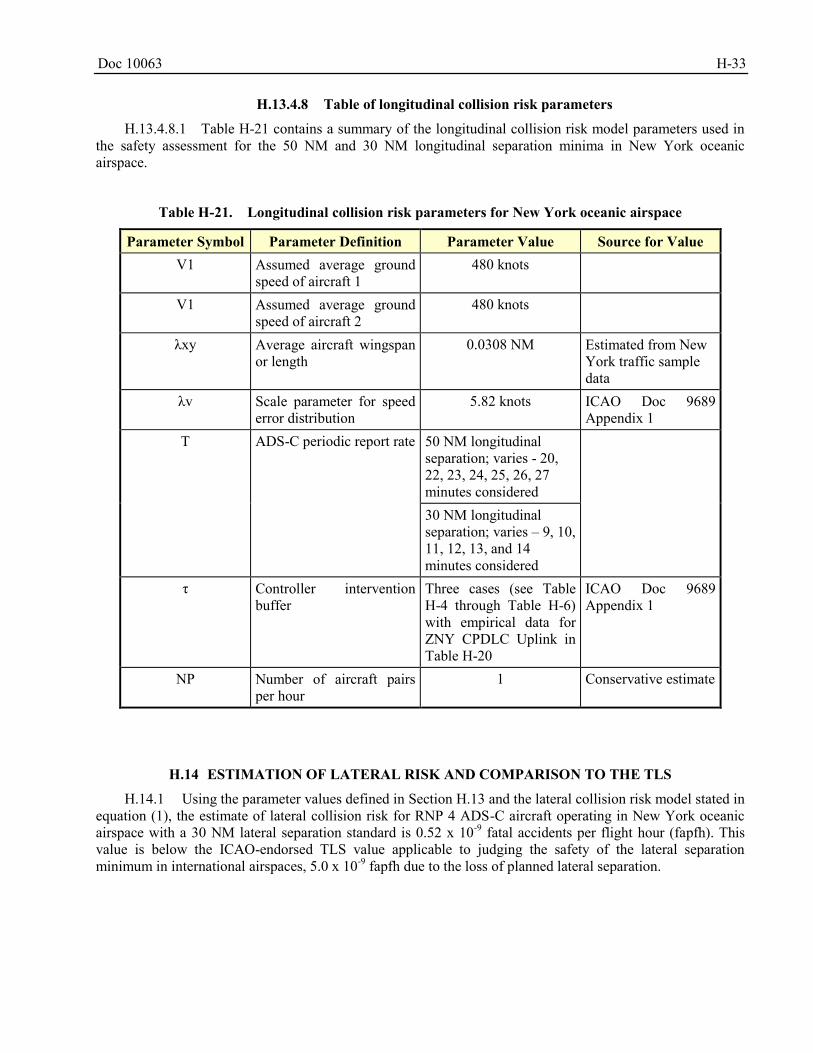
Doc 10063 H-33
H.13.4.8 Table of longitudinal collision risk parameters
H.13.4.8.1 Table H-21 contains a summary of the longitudinal collision risk model parameters used in the safety assessment for the 50 NM and 30 NM longitudinal separation minima in New York oceanic airspace.
Table H-21. Longitudinal collision risk parameters for New York oceanic airspace
Parameter Symbol Parameter Definition Parameter Value Source for Value V1 Assumed average ground
speed of aircraft 1 480 knots
V1 Assumed average ground speed of aircraft 2
480 knots
λxy Average aircraft wingspan or length
0.0308 NM Estimated from New York traffic sample data
λv Scale parameter for speed error distribution
5.82 knots ICAO Doc 9689 Appendix 1
T ADS-C periodic report rate 50 NM longitudinal separation; varies - 20, 22, 23, 24, 25, 26, 27 minutes considered
30 NM longitudinal separation; varies – 9, 10, 11, 12, 13, and 14 minutes considered
τ Controller intervention buffer
Three cases (see Table H-4 through Table H-6) with empirical data for ZNY CPDLC Uplink in Table H-20
ICAO Doc 9689 Appendix 1
NP Number of aircraft pairs per hour
1 Conservative estimate
ESTIMATION OF LATERAL RISK AND COMPARISON TO THE TLS H.14
H.14.1 Using the parameter values defined in Section H.13 and the lateral collision risk model stated in equation (1), the estimate of lateral collision risk for RNP 4 ADS-C aircraft operating in New York oceanic airspace with a 30 NM lateral separation standard is 0.52 x 10⁻⁹ fatal accidents per flight hour (fapfh). This value is below the ICAO-endorsed TLS value applicable to judging the safety of the lateral separation minimum in international airspaces, 5.0 x 10⁻⁹ fapfh due to the loss of planned lateral separation.
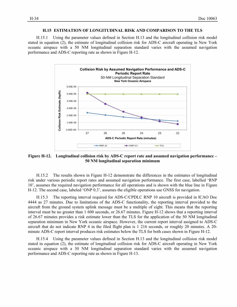
H-34 Doc 10063
ESTIMATION OF LONGITUDINAL RISK AND COMPARISON TO THE TLS H.15
H.15.1 Using the parameter values defined in Section H.13 and the longitudinal collision risk model stated in equation (2), the estimate of longitudinal collision risk for ADS-C aircraft operating in New York oceanic airspace with a 50 NM longitudinal separation standard varies with the assumed navigation performance and ADS-C reporting rate as shown in Figure H-12.
Figure H-12. Longitudinal collision risk by ADS-C report rate and assumed navigation performance –
50 NM longitudinal separation minimum
H.15.2 The results shown in Figure H-12 demonstrate the differences in the estimates of longitudinal risk under various periodic report rates and assumed navigation performance. The first case, labelled ‘RNP 10’, assumes the required navigation performance for all operations and is shown with the blue line in Figure H-12. The second case, labeled ‘ONP 0.3’, assumes the eligible operations use GNSS for navigation.
H.15.3 The reporting interval required for ADS-C/CPDLC RNP 10 aircraft is provided in ICAO Doc 4444 as 27 minutes. Due to limitations of the ADS-C functionality, the reporting interval provided to the aircraft from the ground system uplink message must be a multiple of eight. This means that the reporting interval must be no greater than 1 600 seconds, or 26.67 minutes. Figure H-12 shows that a reporting interval of 26.67 minutes provides a risk estimate lower than the TLS for the application of the 50 NM longitudinal separation minimum in New York oceanic airspace. However, the current report interval assigned to ADS-C aircraft that do not indicate RNP 4 in the filed flight plan is 1 216 seconds, or roughly 20 minutes. A 20-minute ADS-C report interval produces risk estimates below the TLS for both cases shown in Figure H-12.
H.15.4 Using the parameter values defined in Section H.13 and the longitudinal collision risk model stated in equation (2), the estimate of longitudinal collision risk for ADS-C aircraft operating in New York oceanic airspace with a 30 NM longitudinal separation standard varies with the assumed navigation performance and ADS-C reporting rate as shown in Figure H-13.
0.00E+00
1.00E-09
2.00E-09
3.00E-09
4.00E-09
5.00E-09
6.00E-09
27 26 25 24 23 22
Col
lisio
n R
isk
Estim
ate
(fapf
h)
ADS-C Periodic Report Rate (minutes)
Collision Risk by Assumed Navigation Performance and ADS-C Periodic Report Rate
50-NM Longitudinal Separation StandardNew York Oceanic Airspace
RNP 10 ONP 0.3 TLS
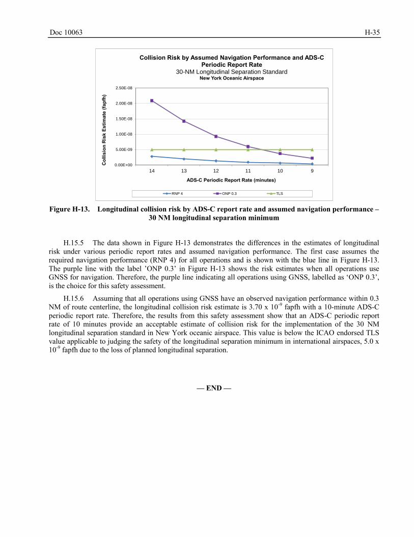
Doc 10063 H-35
Figure H-13. Longitudinal collision risk by ADS-C report rate and assumed navigation performance –
30 NM longitudinal separation minimum
H.15.5 The data shown in Figure H-13 demonstrates the differences in the estimates of longitudinal risk under various periodic report rates and assumed navigation performance. The first case assumes the required navigation performance (RNP 4) for all operations and is shown with the blue line in Figure H-13. The purple line with the label ’ONP 0.3’ in Figure H-13 shows the risk estimates when all operations use GNSS for navigation. Therefore, the purple line indicating all operations using GNSS, labelled as ‘ONP 0.3’, is the choice for this safety assessment.
H.15.6 Assuming that all operations using GNSS have an observed navigation performance within 0.3 NM of route centerline, the longitudinal collision risk estimate is 3.70 x 10⁻⁹ fapfh with a 10-minute ADS-C periodic report rate. Therefore, the results from this safety assessment show that an ADS-C periodic report rate of 10 minutes provide an acceptable estimate of collision risk for the implementation of the 30 NM longitudinal separation standard in New York oceanic airspace. This value is below the ICAO endorsed TLS value applicable to judging the safety of the longitudinal separation minimum in international airspaces, 5.0 x 10⁻⁹ fapfh due to the loss of planned longitudinal separation.
— END —
0.00E+00
5.00E-09
1.00E-08
1.50E-08
2.00E-08
2.50E-08
14 13 12 11 10 9
Col
lisio
n R
isk
Estim
ate
(fapf
h)
ADS-C Periodic Report Rate (minutes)
Collision Risk by Assumed Navigation Performance and ADS-C Periodic Report Rate
30-NM Longitudinal Separation StandardNew York Oceanic Airspace
RNP 4 ONP 0.3 TLS
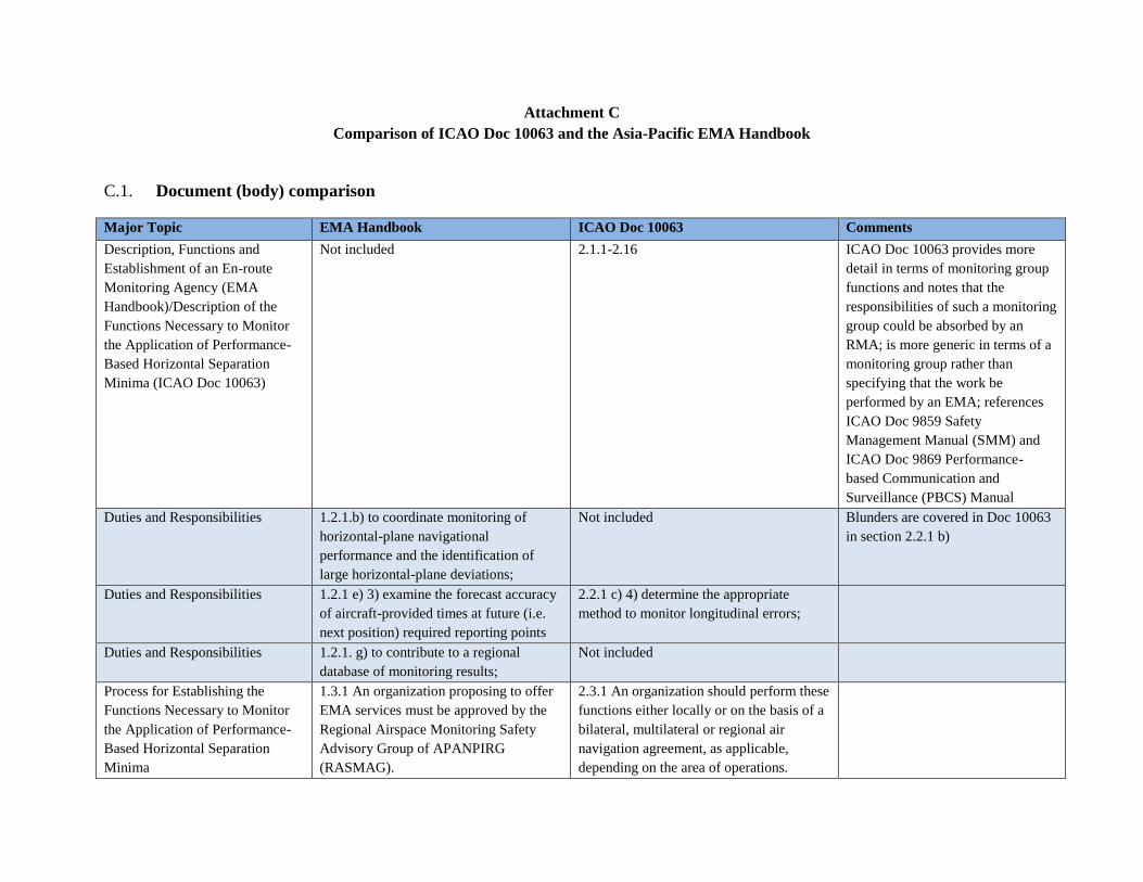
Attachment C
Comparison of ICAO Doc 10063 and the Asia-Pacific EMA Handbook
C.1. Document (body) comparison
Major Topic EMA Handbook ICAO Doc 10063 Comments
Description, Functions and
Establishment of an En-route
Monitoring Agency (EMA
Handbook)/Description of the
Functions Necessary to Monitor
the Application of Performance-
Based Horizontal Separation
Minima (ICAO Doc 10063)
Not included 2.1.1-2.16 ICAO Doc 10063 provides more
detail in terms of monitoring group
functions and notes that the
responsibilities of such a monitoring
group could be absorbed by an
RMA; is more generic in terms of a
monitoring group rather than
specifying that the work be
performed by an EMA; references
ICAO Doc 9859 Safety
Management Manual (SMM) and
ICAO Doc 9869 Performance-
based Communication and
Surveillance (PBCS) Manual
Duties and Responsibilities 1.2.1.b) to coordinate monitoring of
horizontal-plane navigational
performance and the identification of
large horizontal-plane deviations;
Not included Blunders are covered in Doc 10063
in section 2.2.1 b)
Duties and Responsibilities 1.2.1 e) 3) examine the forecast accuracy
of aircraft-provided times at future (i.e.
next position) required reporting points
2.2.1 c) 4) determine the appropriate
method to monitor longitudinal errors;
Duties and Responsibilities 1.2.1. g) to contribute to a regional
database of monitoring results;
Not included
Process for Establishing the
Functions Necessary to Monitor
the Application of Performance-
Based Horizontal Separation
Minima
1.3.1 An organization proposing to offer
EMA services must be approved by the
Regional Airspace Monitoring Safety
Advisory Group of APANPIRG
(RASMAG).
2.3.1 An organization should perform these
functions either locally or on the basis of a
bilateral, multilateral or regional air
navigation agreement, as applicable,
depending on the area of operations.
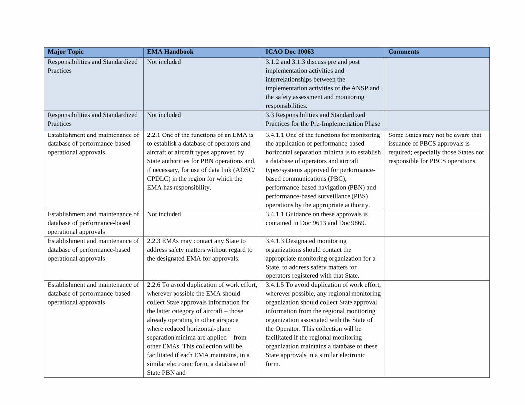
Major Topic EMA Handbook ICAO Doc 10063 Comments
Responsibilities and Standardized
Practices
Not included 3.1.2 and 3.1.3 discuss pre and post
implementation activities and
interrelationships between the
implementation activities of the ANSP and
the safety assessment and monitoring
responsibilities.
Responsibilities and Standardized
Practices
Not included 3.3 Responsibilities and Standardized
Practices for the Pre-Implementation Phase
Establishment and maintenance of
database of performance-based
operational approvals
2.2.1 One of the functions of an EMA is
to establish a database of operators and
aircraft or aircraft types approved by
State authorities for PBN operations and,
if necessary, for use of data link (ADSC/
CPDLC) in the region for which the
EMA has responsibility.
3.4.1.1 One of the functions for monitoring
the application of performance-based
horizontal separation minima is to establish
a database of operators and aircraft
types/systems approved for performance-
based communications (PBC),
performance-based navigation (PBN) and
performance-based surveillance (PBS)
operations by the appropriate authority.
Some States may not be aware that
issuance of PBCS approvals is
required; especially those States not
responsible for PBCS operations.
Establishment and maintenance of
database of performance-based
operational approvals
Not included 3.4.1.1 Guidance on these approvals is
contained in Doc 9613 and Doc 9869.
Establishment and maintenance of
database of performance-based
operational approvals
2.2.3 EMAs may contact any State to
address safety matters without regard to
the designated EMA for approvals.
3.4.1.3 Designated monitoring
organizations should contact the
appropriate monitoring organization for a
State, to address safety matters for
operators registered with that State.
Establishment and maintenance of
database of performance-based
operational approvals
2.2.6 To avoid duplication of work effort,
wherever possible the EMA should
collect State approvals information for
the latter category of aircraft – those
already operating in other airspace
where reduced horizontal-plane
separation minima are applied – from
other EMAs. This collection will be
facilitated if each EMA maintains, in a
similar electronic form, a database of
State PBN and
3.4.1.5 To avoid duplication of work effort,
wherever possible, any regional monitoring
organization should collect State approval
information from the regional monitoring
organization associated with the State of
the Operator. This collection will be
facilitated if the regional monitoring
organization maintains a database of these
State approvals in a similar electronic
form.
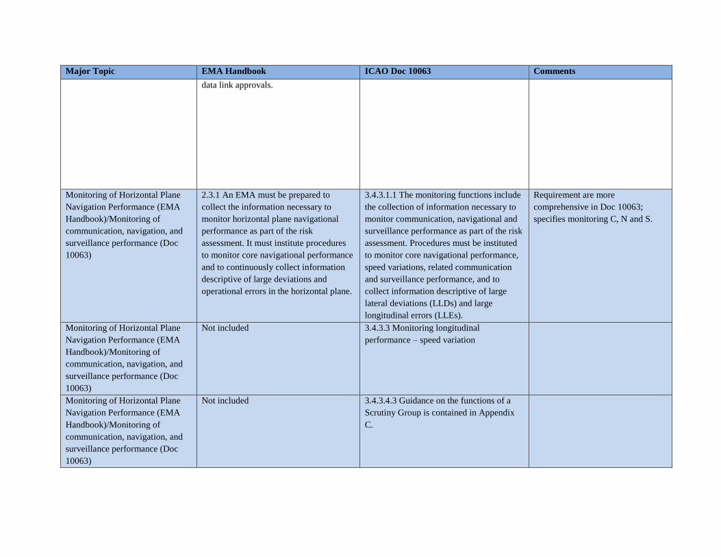
Major Topic EMA Handbook ICAO Doc 10063 Comments
data link approvals.
Monitoring of Horizontal Plane
Navigation Performance (EMA
Handbook)/Monitoring of
communication, navigation, and
surveillance performance (Doc
10063)
2.3.1 An EMA must be prepared to
collect the information necessary to
monitor horizontal plane navigational
performance as part of the risk
assessment. It must institute procedures
to monitor core navigational performance
and to continuously collect information
descriptive of large deviations and
operational errors in the horizontal plane.
3.4.3.1.1 The monitoring functions include
the collection of information necessary to
monitor communication, navigational and
surveillance performance as part of the risk
assessment. Procedures must be instituted
to monitor core navigational performance,
speed variations, related communication
and surveillance performance, and to
collect information descriptive of large
lateral deviations (LLDs) and large
longitudinal errors (LLEs).
Requirement are more
comprehensive in Doc 10063;
specifies monitoring C, N and S.
Monitoring of Horizontal Plane
Navigation Performance (EMA
Handbook)/Monitoring of
communication, navigation, and
surveillance performance (Doc
10063)
Not included 3.4.3.3 Monitoring longitudinal
performance – speed variation
Monitoring of Horizontal Plane
Navigation Performance (EMA
Handbook)/Monitoring of
communication, navigation, and
surveillance performance (Doc
10063)
Not included 3.4.3.4.3 Guidance on the functions of a
Scrutiny Group is contained in Appendix
C.
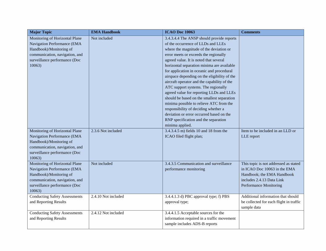
Major Topic EMA Handbook ICAO Doc 10063 Comments
Monitoring of Horizontal Plane
Navigation Performance (EMA
Handbook)/Monitoring of
communication, navigation, and
surveillance performance (Doc
10063)
Not included 3.4.3.4.4 The ANSP should provide reports
of the occurrence of LLDs and LLEs
where the magnitude of the deviation or
error meets or exceeds the regionally
agreed value. It is noted that several
horizontal separation minima are available
for application in oceanic and procedural
airspace depending on the eligibility of the
aircraft operator and the capability of the
ATC support systems. The regionally
agreed value for reporting LLDs and LLEs
should be based on the smallest separation
minima possible to relieve ATC from the
responsibility of deciding whether a
deviation or error occurred based on the
RNP specification and the separation
minima applied.
Monitoring of Horizontal Plane
Navigation Performance (EMA
Handbook)/Monitoring of
communication, navigation, and
surveillance performance (Doc
10063)
2.3.6 Not included 3.4.3.4.5 m) fields 10 and 18 from the
ICAO filed flight plan;
Item to be included in an LLD or
LLE report
Monitoring of Horizontal Plane
Navigation Performance (EMA
Handbook)/Monitoring of
communication, navigation, and
surveillance performance (Doc
10063)
Not included 3.4.3.5 Communication and surveillance
performance monitoring
This topic is not addressed as stated
in ICAO Doc 10063 in the EMA
Handbook; the EMA Handbook
includes 2.4.13 Data Link
Performance Monitoring
Conducting Safety Assessments
and Reporting Results
2.4.10 Not included 3.4.4.1.3 d) PBC approval type; f) PBS
approval type;
Additional information that should
be collected for each flight in traffic
sample data
Conducting Safety Assessments
and Reporting Results
2.4.12 Not included 3.4.4.1.5 Acceptable sources for the
information required in a traffic movement
sample includes ADS-B reports
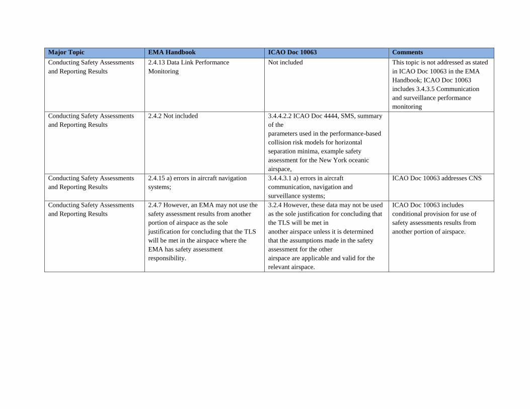
Major Topic EMA Handbook ICAO Doc 10063 Comments
Conducting Safety Assessments
and Reporting Results
2.4.13 Data Link Performance
Monitoring
Not included This topic is not addressed as stated
in ICAO Doc 10063 in the EMA
Handbook; ICAO Doc 10063
includes 3.4.3.5 Communication
and surveillance performance
monitoring
Conducting Safety Assessments
and Reporting Results
2.4.2 Not included 3.4.4.2.2 ICAO Doc 4444, SMS, summary
of the
parameters used in the performance-based
collision risk models for horizontal
separation minima, example safety
assessment for the New York oceanic
airspace,
Conducting Safety Assessments
and Reporting Results
2.4.15 a) errors in aircraft navigation
systems;
3.4.4.3.1 a) errors in aircraft
communication, navigation and
surveillance systems;
ICAO Doc 10063 addresses CNS
Conducting Safety Assessments
and Reporting Results
2.4.7 However, an EMA may not use the
safety assessment results from another
portion of airspace as the sole
justification for concluding that the TLS
will be met in the airspace where the
EMA has safety assessment
responsibility.
3.2.4 However, these data may not be used
as the sole justification for concluding that
the TLS will be met in
another airspace unless it is determined
that the assumptions made in the safety
assessment for the other
airspace are applicable and valid for the
relevant airspace.
ICAO Doc 10063 includes
conditional provision for use of
safety assessments results from
another portion of airspace.
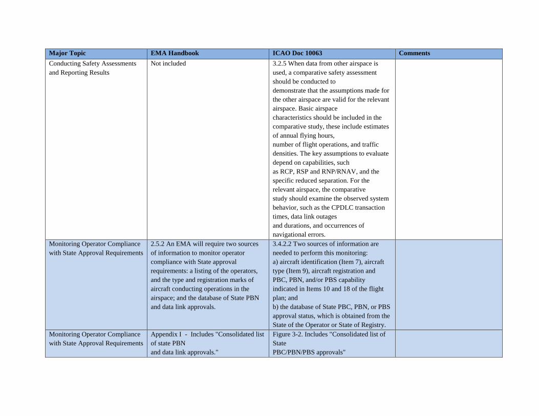
Major Topic EMA Handbook ICAO Doc 10063 Comments
Conducting Safety Assessments
and Reporting Results
Not included 3.2.5 When data from other airspace is
used, a comparative safety assessment
should be conducted to
demonstrate that the assumptions made for
the other airspace are valid for the relevant
airspace. Basic airspace
characteristics should be included in the
comparative study, these include estimates
of annual flying hours,
number of flight operations, and traffic
densities. The key assumptions to evaluate
depend on capabilities, such
as RCP, RSP and RNP/RNAV, and the
specific reduced separation. For the
relevant airspace, the comparative
study should examine the observed system
behavior, such as the CPDLC transaction
times, data link outages
and durations, and occurrences of
navigational errors.
Monitoring Operator Compliance
with State Approval Requirements
2.5.2 An EMA will require two sources
of information to monitor operator
compliance with State approval
requirements: a listing of the operators,
and the type and registration marks of
aircraft conducting operations in the
airspace; and the database of State PBN
and data link approvals.
3.4.2.2 Two sources of information are
needed to perform this monitoring:
a) aircraft identification (Item 7), aircraft
type (Item 9), aircraft registration and
PBC, PBN, and/or PBS capability
indicated in Items 10 and 18 of the flight
plan; and
b) the database of State PBC, PBN, or PBS
approval status, which is obtained from the
State of the Operator or State of Registry.
Monitoring Operator Compliance
with State Approval Requirements
Appendix I - Includes "Consolidated list
of state PBN
and data link approvals."
Figure 3-2. Includes "Consolidated list of
State
PBC/PBN/PBS approvals"
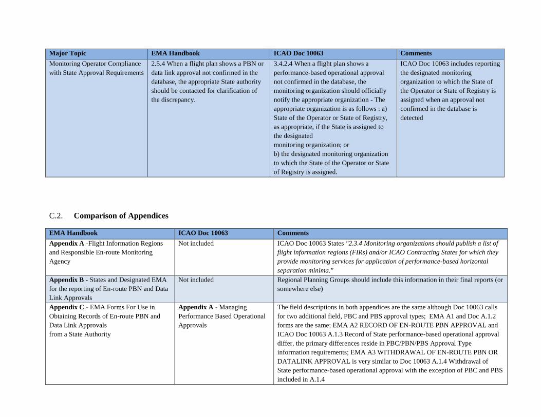
Major Topic EMA Handbook ICAO Doc 10063 Comments
Monitoring Operator Compliance
with State Approval Requirements
2.5.4 When a flight plan shows a PBN or
data link approval not confirmed in the
database, the appropriate State authority
should be contacted for clarification of
the discrepancy.
3.4.2.4 When a flight plan shows a
performance-based operational approval
not confirmed in the database, the
monitoring organization should officially
notify the appropriate organization - The
appropriate organization is as follows : a)
State of the Operator or State of Registry,
as appropriate, if the State is assigned to
the designated
monitoring organization; or
b) the designated monitoring organization
to which the State of the Operator or State
of Registry is assigned.
ICAO Doc 10063 includes reporting
the designated monitoring
organization to which the State of
the Operator or State of Registry is
assigned when an approval not
confirmed in the database is
detected
C.2. Comparison of Appendices
EMA Handbook ICAO Doc 10063 Comments
Appendix A -Flight Information Regions
and Responsible En-route Monitoring
Agency
Not included ICAO Doc 10063 States "2.3.4 Monitoring organizations should publish a list of
flight information regions (FIRs) and/or ICAO Contracting States for which they
provide monitoring services for application of performance-based horizontal
separation minima."
Appendix B - States and Designated EMA
for the reporting of En-route PBN and Data
Link Approvals
Not included Regional Planning Groups should include this information in their final reports (or
somewhere else)
Appendix C - EMA Forms For Use in
Obtaining Records of En-route PBN and
Data Link Approvals
from a State Authority
Appendix A - Managing
Performance Based Operational
Approvals
The field descriptions in both appendices are the same although Doc 10063 calls
for two additional field, PBC and PBS approval types; EMA A1 and Doc A.1.2
forms are the same; EMA A2 RECORD OF EN-ROUTE PBN APPROVAL and
ICAO Doc 10063 A.1.3 Record of State performance-based operational approval
differ, the primary differences reside in PBC/PBN/PBS Approval Type
information requirements; EMA A3 WITHDRAWAL OF EN-ROUTE PBN OR
DATALINK APPROVAL is very similar to Doc 10063 A.1.4 Withdrawal of
State performance-based operational approval with the exception of PBC and PBS
included in A.1.4
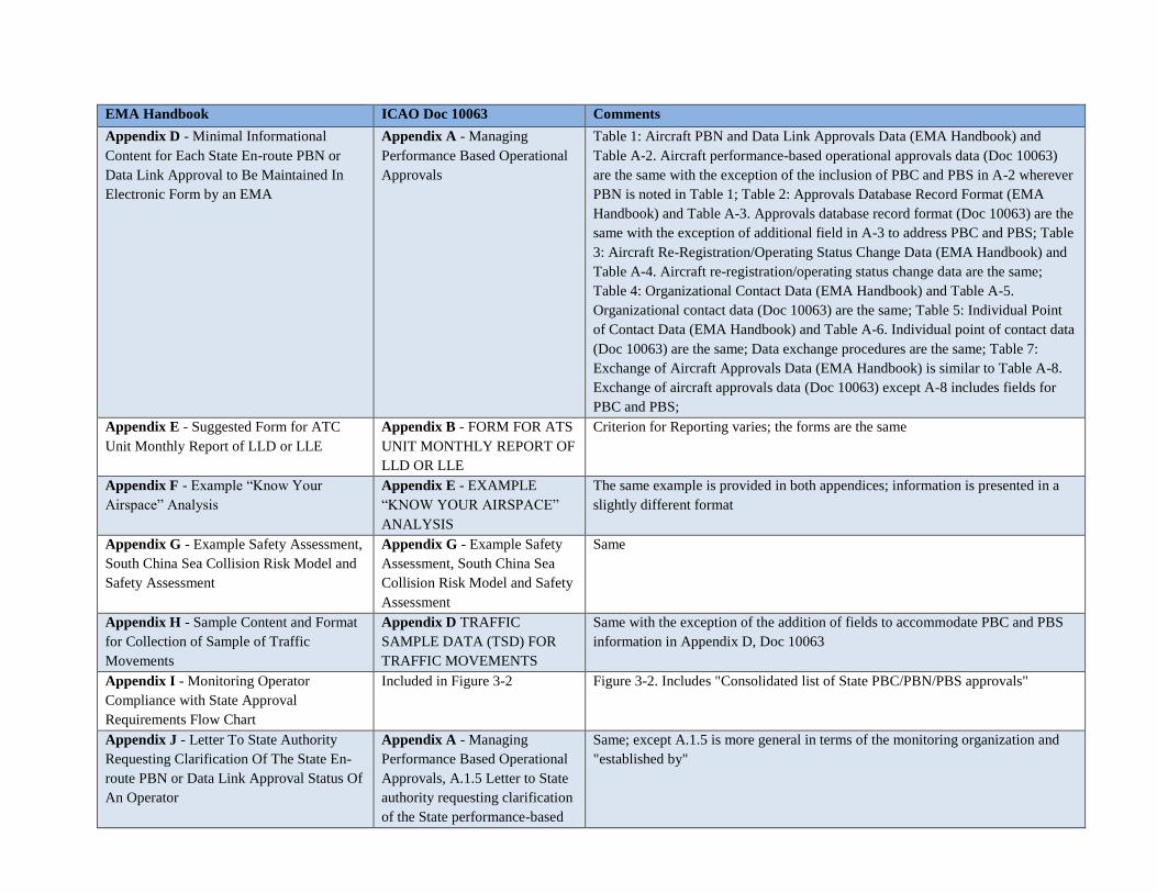
EMA Handbook ICAO Doc 10063 Comments
Appendix D - Minimal Informational
Content for Each State En-route PBN or
Data Link Approval to Be Maintained In
Electronic Form by an EMA
Appendix A - Managing
Performance Based Operational
Approvals
Table 1: Aircraft PBN and Data Link Approvals Data (EMA Handbook) and
Table A-2. Aircraft performance-based operational approvals data (Doc 10063)
are the same with the exception of the inclusion of PBC and PBS in A-2 wherever
PBN is noted in Table 1; Table 2: Approvals Database Record Format (EMA
Handbook) and Table A-3. Approvals database record format (Doc 10063) are the
same with the exception of additional field in A-3 to address PBC and PBS; Table
3: Aircraft Re-Registration/Operating Status Change Data (EMA Handbook) and
Table A-4. Aircraft re-registration/operating status change data are the same;
Table 4: Organizational Contact Data (EMA Handbook) and Table A-5.
Organizational contact data (Doc 10063) are the same; Table 5: Individual Point
of Contact Data (EMA Handbook) and Table A-6. Individual point of contact data
(Doc 10063) are the same; Data exchange procedures are the same; Table 7:
Exchange of Aircraft Approvals Data (EMA Handbook) is similar to Table A-8.
Exchange of aircraft approvals data (Doc 10063) except A-8 includes fields for
PBC and PBS;
Appendix E - Suggested Form for ATC
Unit Monthly Report of LLD or LLE
Appendix B - FORM FOR ATS
UNIT MONTHLY REPORT OF
LLD OR LLE
Criterion for Reporting varies; the forms are the same
Appendix F - Example “Know Your
Airspace” Analysis
Appendix E - EXAMPLE
“KNOW YOUR AIRSPACE”
ANALYSIS
The same example is provided in both appendices; information is presented in a
slightly different format
Appendix G - Example Safety Assessment,
South China Sea Collision Risk Model and
Safety Assessment
Appendix G - Example Safety
Assessment, South China Sea
Collision Risk Model and Safety
Assessment
Same
Appendix H - Sample Content and Format
for Collection of Sample of Traffic
Movements
Appendix D TRAFFIC
SAMPLE DATA (TSD) FOR
TRAFFIC MOVEMENTS
Same with the exception of the addition of fields to accommodate PBC and PBS
information in Appendix D, Doc 10063
Appendix I - Monitoring Operator
Compliance with State Approval
Requirements Flow Chart
Included in Figure 3-2 Figure 3-2. Includes "Consolidated list of State PBC/PBN/PBS approvals"
Appendix J - Letter To State Authority
Requesting Clarification Of The State En-
route PBN or Data Link Approval Status Of
An Operator
Appendix A - Managing
Performance Based Operational
Approvals, A.1.5 Letter to State
authority requesting clarification
of the State performance-based
Same; except A.1.5 is more general in terms of the monitoring organization and
"established by"
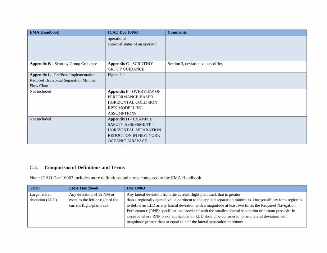
EMA Handbook ICAO Doc 10063 Comments
operational
approval status of an operator
Appendix K - Scrutiny Group Guidance Appendix C - SCRUTINY
GROUP GUIDANCE
Section 3, deviation values differ;
Appendix L - Pre/Post-Implementation
Reduced Horizontal Separation Minima
Flow Chart
Figure 3-1
Not included Appendix F - OVERVIEW OF
PERFORMANCE-BASED
HORIZONTAL COLLISION
RISK MODELLING
ASSUMPTIONS
Not included Appendix H - EXAMPLE
SAFETY ASSESSMENT –
HORIZONTAL SEPARATION
REDUCTION IN NEW YORK
OCEANIC AIRSPACE
C.3. Comparison of Definitions and Terms
Note: ICAO Doc 10063 includes more definitions and terms compared to the EMA Handbook
Term EMA Handbook Doc 10063
Large lateral
deviation (LLD)
Any deviation of 15 NM or
more to the left or right of the
current flight-plan track.
Any lateral deviation from the current flight plan track that is greater
than a regionally agreed value pertinent to the applied separation minimum. One possibility for a region is
to define an LLD as any lateral deviation with a magnitude at least two times the Required Navigation
Performance (RNP) specification associated with the smallest lateral separation minimum possible. In
airspace where RNP is not applicable, an LLD should be considered to be a lateral deviation with
magnitude greater than or equal to half the lateral separation minimum.
Related Documents


