www.ijsetr.com ISSN 2319-8885 Vol.04,Issue.31, August-2015, Pages:5940-5948 Copyright @ 2015 IJSETR. All rights reserved. Comparison of SEIG & DFIG with STATCOM Control for AC Loads G. P. MERLINE 1 , KONDAL RAO DAGGUMATI 2 1 PG Scholar, Dept of EEE, Arjun College of Technology and Science, Hayath Nagar, Ranga Reddy, TS, India. 2 Asst Prof, Dept of EEE, Arjun College of Technology and Science, Hayath Nagar, Ranga Reddy, TS, India. Abstract: This paper deals with the comparative analysis of static compensator (STATCOM) based voltage regulator for self- excited induction generators (SEIGs) and double fed induction generator (DFIG) supplying non-linear loads. In practice, a number of loads are non-linear in nature and therefore they inject harmonics in the generating systems. The SEIG being a weak isolated system, its performance is very much affected by these harmonics. The additional drawbacks of SEIG are poor voltage regulation and it requires adjustable reactive power source with varying load to maintain constant terminal voltage. Coordination of STATCOM and DFIG becomes necessary during steady-state as STATCOM exists in the system to improve the fault-ride through capability of DFIG. This paper aims to perform the coordination by means of minimizing the power loss of the system. As reactive power flow in the system has direct impact on the loss of the system, utilizing reactive power sources effectively can reduce the loss. Stator of DFIG, Grid-side converter (GSC) of DFIG and STATCOM are considered to be the sources of reactive power supplying a local load. An optimization algorithm is proposed and MATLAB optimization toolbox is used to implement the algorithm. Since the loss of GSC is found to be smaller in compare to the loss of STATCOM, investing in larger GSC is suggested in order to minimize the loss of the system. Keywords: Self-Excited Induction Generator (SEIG), Double-Fed Induction Generator (DFIG), Single Phase Synchronous D-Q Frame Theory, Static Synchronous Compensator (STATCOM). I. INTRODUCTION In remote areas, plenty of non-conventional energy sources are available. These non-conventional energy sources are identified as potential prime movers for the generating systems. Externally driven induction machine operates as a self-excited induction generator (SEIG) with its excitation requirements being met by a capacitor bank connected across its terminals. The SEIG has advantages like simplicity, maintenance free, absence of DC, brushless etc. as compared to the conventional synchronous generator. A considerable reported literature exists on steady state and transient analysis of SEIG under balanced/unbalanced resistive, reactive and motor loads. In [1-3] d-q axes modeling is reported for the transient analysis of SEIG. Wang and Deng [4] have presented the transient performance of the SEIG under unbalanced excitation system. Jain et al. [5] have given a generalized model for the transient analysis of SEIG under symmetrical and unsymmetrical conditions. A major disadvantage of SEIG is its poor voltage regulation requires a variable capacitance bank to maintain constant terminal voltage under varying loads. Attempts have been made to maintain constant terminal voltage by fixed capacitor and thyristor controlled inductor (SVC) [6], saturable-core reactor [7] and short-shunt connection [8], However, voltage regulation provided by these schemes is of discrete type and inject harmonics in the generating system. By the invention of solid-state self-commutating devices, it is possible to make a static, noiseless voltage regulator, which can provide continuously variable reactive power to the SEIG with varying load to keep terminal voltage constant. This system called STATCOM has specific benefits compared to SVC [9], Schauder and Mehta [10] have derived governing equations of STATCOM to determine the response of the STATCOM. Fig.1. Schematic diagram of the SEIG–STATCOM system feeding single-phase loads.

Welcome message from author
This document is posted to help you gain knowledge. Please leave a comment to let me know what you think about it! Share it to your friends and learn new things together.
Transcript
www.ijsetr.com
ISSN 2319-8885
Vol.04,Issue.31,
August-2015,
Pages:5940-5948
Copyright @ 2015 IJSETR. All rights reserved.
Comparison of SEIG & DFIG with STATCOM Control for AC Loads G. P. MERLINE
1, KONDAL RAO DAGGUMATI
2
1PG Scholar, Dept of EEE, Arjun College of Technology and Science, Hayath Nagar, Ranga Reddy, TS, India. 2Asst Prof, Dept of EEE, Arjun College of Technology and Science, Hayath Nagar, Ranga Reddy, TS, India.
Abstract: This paper deals with the comparative analysis of static compensator (STATCOM) based voltage regulator for self-
excited induction generators (SEIGs) and double fed induction generator (DFIG) supplying non-linear loads. In practice, a
number of loads are non-linear in nature and therefore they inject harmonics in the generating systems. The SEIG being a weak
isolated system, its performance is very much affected by these harmonics. The additional drawbacks of SEIG are poor voltage
regulation and it requires adjustable reactive power source with varying load to maintain constant terminal voltage. Coordination
of STATCOM and DFIG becomes necessary during steady-state as STATCOM exists in the system to improve the fault-ride
through capability of DFIG. This paper aims to perform the coordination by means of minimizing the power loss of the system.
As reactive power flow in the system has direct impact on the loss of the system, utilizing reactive power sources effectively can
reduce the loss. Stator of DFIG, Grid-side converter (GSC) of DFIG and STATCOM are considered to be the sources of reactive
power supplying a local load. An optimization algorithm is proposed and MATLAB optimization toolbox is used to implement
the algorithm. Since the loss of GSC is found to be smaller in compare to the loss of STATCOM, investing in larger GSC is
suggested in order to minimize the loss of the system.
Keywords: Self-Excited Induction Generator (SEIG), Double-Fed Induction Generator (DFIG), Single Phase Synchronous D-Q
Frame Theory, Static Synchronous Compensator (STATCOM).
I. INTRODUCTION
In remote areas, plenty of non-conventional energy sources
are available. These non-conventional energy sources are
identified as potential prime movers for the generating
systems. Externally driven induction machine operates as a
self-excited induction generator (SEIG) with its excitation
requirements being met by a capacitor bank connected across
its terminals. The SEIG has advantages like simplicity,
maintenance free, absence of DC, brushless etc. as compared
to the conventional synchronous generator. A considerable
reported literature exists on steady state and transient analysis
of SEIG under balanced/unbalanced resistive, reactive and
motor loads. In [1-3] d-q axes modeling is reported for the
transient analysis of SEIG. Wang and Deng [4] have
presented the transient performance of the SEIG under
unbalanced excitation system. Jain et al. [5] have given a
generalized model for the transient analysis of SEIG under
symmetrical and unsymmetrical conditions. A major
disadvantage of SEIG is its poor voltage regulation requires a
variable capacitance bank to maintain constant terminal
voltage under varying loads. Attempts have been made to
maintain constant terminal voltage by fixed capacitor and
thyristor controlled inductor (SVC) [6], saturable-core reactor
[7] and short-shunt connection [8], However, voltage
regulation provided by these schemes is of discrete type and
inject harmonics in the generating system. By the invention
of solid-state self-commutating devices, it is possible to make
a static, noiseless voltage regulator, which can provide
continuously variable reactive power to the SEIG with
varying load to keep terminal voltage constant. This system
called STATCOM has specific benefits compared to SVC
[9], Schauder and Mehta [10] have derived governing
equations of STATCOM to determine the response of the
STATCOM.
Fig.1. Schematic diagram of the SEIG–STATCOM
system feeding single-phase loads.
G. P. MERLINE, KONDAL RAO DAGGUMATI
International Journal of Scientific Engineering and Technology Research
Volume.04, IssueNo.31, August-2015, Pages: 5940--5948
The other suggested controllers in literature like switched
capacitor, thyristor controlled inductor [4], saturable core
reactor [5], and series capacitor [6] do not meet such
requirements. With rapid advances in power electronics and
signal processing, static compensator (STATCOM) can be an
attractive reactive power controller. While use of STATCOM
for power systems [7] and for selfexcited induction generator
has been already reported [8-9] under balanced condition, its
applicability to SEIG under unbalanced conditions has not
been explored. Here the total system comprising SEIG;
STATCOM and a general balanced/unbalanced load is
modeled and analyzed for transients/dynamic performance
under realistic load conditions for both resistive and partially
reactive load. The simulated results demonstrate that the use
of STATCOM with SEIG has applicability for three-phase
power generation under all types of balanced/unbalanced
loads.
II. SYSTEM CONFIGURATION AND PRINCIPLE OF
OPERATION
Fig.1 shows the schematic diagram of the STATCOM
compensated three-phase SEIG feeding single-phase loads.
The system consists of an SEIG driven by renewable energy-
based prime mover. The single-phase consumer loads are
connected across “a” and “c” phases of the SEIG. A two-
level, three-leg insulated-gate bipolar transistor (IGBT)-
based VSI with a self sustaining dc-bus capacitor is used as a
STATCOM. The STATCOM is connected at point of
common coupling (PCC) through filter inductors as shown in
Fig.1.
Fig.2.Block diagram of the single-phase synchronous D-Q
theory control algorithm for the STATCOM.
The STATCOM regulates the system voltage by
maintaining equilibrium among the reactive power
circulations within the system. Moreover, the STATCOM
suppresses harmonics injected by nonlinear loads and
provides load balancing while feeding single-phase loads.
The unbalanced load currents in a three-phase system can be
divided into two sets of balanced currents known as positive
sequence components and negative sequence components. In
order to achieve balanced source currents, the source should
be free from the negative sequence components of load
currents. Therefore, when the STATCOM is connected
across PCC, it supplies the negative sequence currents
needed by the unbalanced load or it draws another set of
negative sequence currents which are exactly180◦ out of
phase to those drawn by unbalanced load so as to nullify the
effect of negative sequence currents of unbalanced loads.
III. DOUBLY-FED INDUCTION GENERATOR
Wind is a continuously varying source of energy and so is
the active power generated by the wind turbine. If a WT is
connected to a weak grid (which has low short circuit power),
the terminal voltage also fluctuates, producing flicker,
harmonics and interharmonics due to the presence of power
electronics. For a set of connected wind turbines forming a
wind farm, there exist certain grid codes or specific
requirements with which each wind turbine must conform
with in order to be allowed to be connected to the grid. Most
wind power systems are based in remote rural locations and
are therefore prone to voltage sags, faults, and unbalances.
These unbalanced grid voltages can cause many problems
such as torque pulsations, unbalanced currents and reactive
power pulsations. When wind farms are connected to a strong
grid, that is closer to a stiff source, voltage and frequency can
be quickly re-established after a disturbance with the support
of the power grid itself. To wait for the voltage to re-establish
after the fault has been cleared in the case of a weak grid
interconnection is not reliable because there is always a risk
of voltage instability initiated by the disturbance. Hence,
reactive power and voltage support that can be provided by
mechanically switched capacitors, SVC or STATCOM is
needed to help improve the short term voltage stability and
reinforce the power network. This is also true for wind farms
with all fixed speed wind turbines with no dynamic control or
reactive power compensation.
Fig.3. Block diagram of a Doubly-fed induction
generator.
There are many wind turbine manufacturers who produce
different wind turbine technologies. The high power MW
range WTs are typically the DFIGs which are becoming
increasingly popular with their increasing number of
installations. Wind generators are generally of two types:
fixed and variable speed. Fixed speed generators are

Comparison of SEIG & DFIG with STATCOM Control for AC Loads
International Journal of Scientific Engineering and Technology Research
Volume.04, IssueNo.31, August-2015, Pages: 5940-5948
induction generators with capacitor bank for self-excitation
or two-pole pairs or those which use rotor resistance control.
Variable speed generators are either DFIG (which is a round
rotor machine) or full power converters such as squirrel cage
induction generators, permanent magnet synchronous
generators, or externally magnetized synchronous generators.
Variable speed wind turbines are connected to the grid using
power electronic technology and maximize effective turbine
speed control. Variable speed wind turbines such as DFIGs
are the most popular wind turbines being installed today
because they perform better than the fixed speed wind
turbines during system disturbances. DFIGs are the only class
of wind generators capable of producing reactive power to
maintain unity power factor at the collector bus.
IV. CONTROL ALGORITHM OF THE STATCOM
Fig.2 shows the block diagram of the proposed single-
phase synchronous D-Q frame theory-based control
algorithm for the three-phase STATCOM. The reference
source currents (i∗sa,i∗sb,i∗sc) for regulating the terminal
voltage and current balancing are computed using a single-
phase synchronous D-Q frame theory applied to the three-
phase SEIG system.
A. Single-Phase Synchronous Rotating D-Q Frame
Theory
It is simple to design a controller for a three-phase system
in synchronously rotating D-Q frame because all the time-
varying signals of the system become dc quantities and time-
invariant. In case of a three-phase system, initially, the three-
phase voltages or currents (in abc frame) are transformed to a
stationary frame (α−β) and then to synchronously rotating D-
Q frame. Similarly, to transform an arbitrary signal “x(t)” of
a single-phase system into a synchronously rotating D-Q
frame, initially that variable is transformed into a stationary
α−β frame using the single-phase p-q theory and then to a
synchronously rotating D-Q frame. Therefore, to transform a
signal into a stationary α−β frame, at least two phases are
needed. Hence, a pseudo second phase for the arbitrary signal
x(t) is created by giving 90◦ lag to the original signal. The
original signal represents the component of α-axis and90◦ lag
signal is the β-axis component of stationary reference frame.
Fig.4. Stationary α−β frame and synchronously rotating
D-Q frame representation of vector x (t).
Therefore, an arbitrary periodic signal x(t)with a time
period of “T” can be represented in a stationary α−β frame as
(1)
For a single-phase system, the concept of the stationary
α−β frame and synchronously rotating D-Q frames relative to
an arbitrary periodic signal x(t)is illustrated in Fig.4. The
signal x(t) is represented as vector x, and the vector x can be
decomposed into two components xα and xβ. As the x vector
rotates around the center, its components xα and xβ which
are the projections on the α−β axes vary in time accordingly.
Now, considering that there are synchronously rotating D-Q
coordinates that rotate with the same angular frequency and
direction as x, then the position of x with respect to its
components xD and xQ is same regardless of time.
Therefore, it is clear that the xD and xQ do not vary with
time and only depend on the magnitude of xand its relative
phase with respect to the D-Q rotating frame. The angle θ is
the rotating angle of the D-Q frame and it is defined as
(2)
Where, ω is the angular frequency of the arbitrary variable
x. The relationship between stationary and synchronous
rotating frames can be derived from Fig.4. The components
of the arbitrary single-phase variable x(t) in the stationary
reference frame are transformed into the synchronously
rotating D-Q frame using the transformation matrix “C” as
(3)
Where,
(4)
B. Reference Source Currents Estimation Using Single-
Phase Synchronous Rotating D-Q Frame Theory
The main objective of employing a three-phase STATCOM
in a three-phase SEIG-based standalone power generating
system feeding single-phase consumer loads is to balance the
generator currents so that the generator can be loaded to its
full capacity without derating. The control structure of the
STATCOM employs an ac voltage PI controller to regulate
the system voltage and a dc bus voltage PI controller to
maintain the dc bus capacitor voltage constant and greater
than the peak value of the line voltage of PCC for successful
operation of the STATCOM. The PCC voltages (va, vb, vc),
source currents (isa, isb, isc), load current (il), and dc bus
voltage (Vdc) are sensed and used as feedback signals.
Considering PCC voltages as balanced and sinusoidal, the
amplitude of the PCC voltage (or system voltage) is
estimated as
(5)
Consider one of the three phases at a time and then
transform the voltages and currents of that particular phase
into a Stationary α−β frame, then the PCC voltages and load
current in stationary α−β frame are represented as

G. P. MERLINE, KONDAL RAO DAGGUMATI
International Journal of Scientific Engineering and Technology Research
Volume.04, IssueNo.31, August-2015, Pages: 5940--5948
(6)
(7)
(8)
(9)
(10)
The sinusoidal signal filters based on a second-order
generalized integrator or a sinusoidal signal integrator (SSI)
can be used for creating β-axis signals which are lagging the
original signals. In the present investigation, a filter based on
SSI is used. The SSI filters generate quadrature signals using
system frequency information. Since the system frequency
fluctuates under load perturbations, a PLL is used to
continuously estimate the system frequency, and the
estimated frequency is fed to SSI filters which makes the
proposed control adaptive to frequency fluctuations, thereby
avoids the loss of synchronization of the STATCOM. Now
consider a synchronously rotating D-Q frame for phase “a”
which is rotating in the same direction as va(t), and the
projections of the load currentil(t)to the D-Q axes give the D
and Q components of the load current. Therefore, the D-axis
and Q-axis components of the load current in phase “a” are
estimated as
(11)
Where cosθa and sinθa are estimated using vaα and vaβ as
follows:
(12)
IlaD represents the active power component of the load
current as the signals belong to the same axis are multiplied
and added to estimate the D-axis component, where as IlaQ
represents the reactive power component of the load current
as the orthogonal signals are multiplied and added to derive
the Q-axis component. Similarly, the D-axis and Q-axis
components of the load current in phase “c” are estimated as
(13)
The negative sign of currents in (11) indicates that the
load current in phase “c” is equal to phase “a” but 180◦ out of
phase. As the single-phase load is connected across the
phases “a” and “c,” D-axis and Q-axis components for phase
“b” are not estimated. The D-axis components of the load
current in phases “a” and “c” are added together to obtain an
equivalent D-axis current component of total load on the
SEIG as
(14)
Similarly, an equivalent Q-axis current component of
total load on the system is estimated as
(15)
The equivalent D-axis and Q-axis current components of
total load are decomposed into two parts namely fundamental
and oscillatory parts as
(16)
(17)
The reason for the existence of the oscillatory part is due
to the nonlinear and single-phase nature of connected loads in
the system. Even if the connected loads are linear in nature,
the D and Q components estimated in (12) and (13) would
still contain oscillatory parts due to the unbalance caused by
single-phase loads. To ensure the power quality, the
reference D-axis and Q-axis components of source currents
must be free from these oscillatory components. Hence, the
signals IlD and IlQ are passed through low-pass filters (LPFs)
to extract the fundamental (or dc) components as shown in
Fig.2. To maintain the dc-bus capacitor voltage of the
STATCOM at a reference value, it is sensed and compared
with the reference value and then they obtained voltage error
is processed through a PI controller. The dc-bus voltage error
of the STATCOM Vdcer at kth sampling instant is expressed as
(18)
Where Vdcref(k) and Vdc(k) are the reference and sensed dc-
bus voltages of the STATCOM at kth sampling instant,
respectively. In the present investigation, the dc-bus voltage
reference is set to 400 V. The output of the PI controller for
maintaining a constant dc bus voltage of the STATCOM at
kth sampling instant is expressed as
(19)
Where Iloss is the active power component of the current
(or D-axis current component) that must be supplied to meet
the losses in the STATCOM. Kpd and Kid are the
proportional and integral gain constants of the dc-bus voltage
PI controller, respectively. The source should supply the
power loss component of the current (Iloss) along with the
filtered equivalent D-axis current component of the single-
phase load estimated in (14). In order to ensure balanced and
sinusoidal source currents, the D-axis component of source
currents after compensation must be equal for all the phases
and it should not contain any ripple. Therefore, IlD is added to
Iloss and distributed among all the phases equally to obtain the
D-axis component of the reference source current in each
phase which can be expressed as
(20)
I∗sDph also indicates the active power component of the
current that should be supplied by the source after
compensation. For regulating the system voltage (i.e., PCC
voltage), the STATCOM has to inject the reactive power
component of the current to meet the reactive power demands
of both the load and SEIG. The amount of the reactive power
component of the current to be injected by the STATCOM is
estimated by an ac voltage PI controller. The amplitude of the
PCC voltage computed in (5) is compared with the reference

Comparison of SEIG & DFIG with STATCOM Control for AC Loads
International Journal of Scientific Engineering and Technology Research
Volume.04, IssueNo.31, August-2015, Pages: 5940-5948
voltage. The PCC voltage error Ver(k) at kth sampling instant
is given as
(21)
Where Vtref is the amplitude of the reference PCC voltage
and Vt(k) is the amplitude of sensed three-phase ac voltages at
the PCC terminals, at kth instant. The reference voltage is
selected to maintain the PCC line voltage at 220 V. The
output of the PI controller for maintaining the PCC voltage at
the reference value in kth sampling instant is expressed as
(22)
Where Kpa and Kia are the proportional and integral gain
constants of the PI controller, Ver(k) and Ver(k−1) are the
voltage errors at kth and (k−1)th instants, respectively. IQ(k)is
the equivalent Q-axis component (or reactive power
component) of the current to be supplied by the STATCOM
to meet the reactive power requirements of both the load and
SEIG, thereby it maintains the PCC voltage at the reference
value. The per phase Q-axis component of the reference
source current required to regulate the system voltage is
defined as
(23)
I∗sQph indicates the magnitude of the reactive power
component of the current that should be supplied to each
phase of the source (i.e., SEIG) to achieve the reference
terminal voltage. The value of I∗sQph can be either positive or
negative based on loading conditions. Using the D-axis and
Q-axis components of currents derived in (18) and (21), the
phase “a,” α- axis and β-axis components of the reference
source current can be estimated as
(24)
In the above matrix, the α-axis current represents the
reference source current of actual phase “a,” and the β-axis
current represents the current that is at π/2 phase lag which
belongs to the fictitious phase. Therefore, one can have
(25)
(26)
Three-phase reference source currents (i∗sa, i∗sb, and i∗sc)
are compared with the sensed source currents (isa, isb, and isc)
and the current errors are computed as
(27)
(28)
(29)
These current error signals are fed to the current-controlled
PWM pulse generator for switching the IGBTs of the
STATCOM. Thus, the generated PWM pulses are applied to
the STATCOM to achieve sinusoidal and balanced source
currents along with desired voltage regulation.
V.MATLAB/SIMULINK RESULTS
A: For linear load
Fig.5.Simulink circuit for linear load.
Fig.6. Source voltage and source current.
Fig.7. Source voltage and load current.
G. P. MERLINE, KONDAL RAO DAGGUMATI
International Journal of Scientific Engineering and Technology Research
Volume.04, IssueNo.31, August-2015, Pages: 5940--5948
Fig.8.FFT window for source voltage.
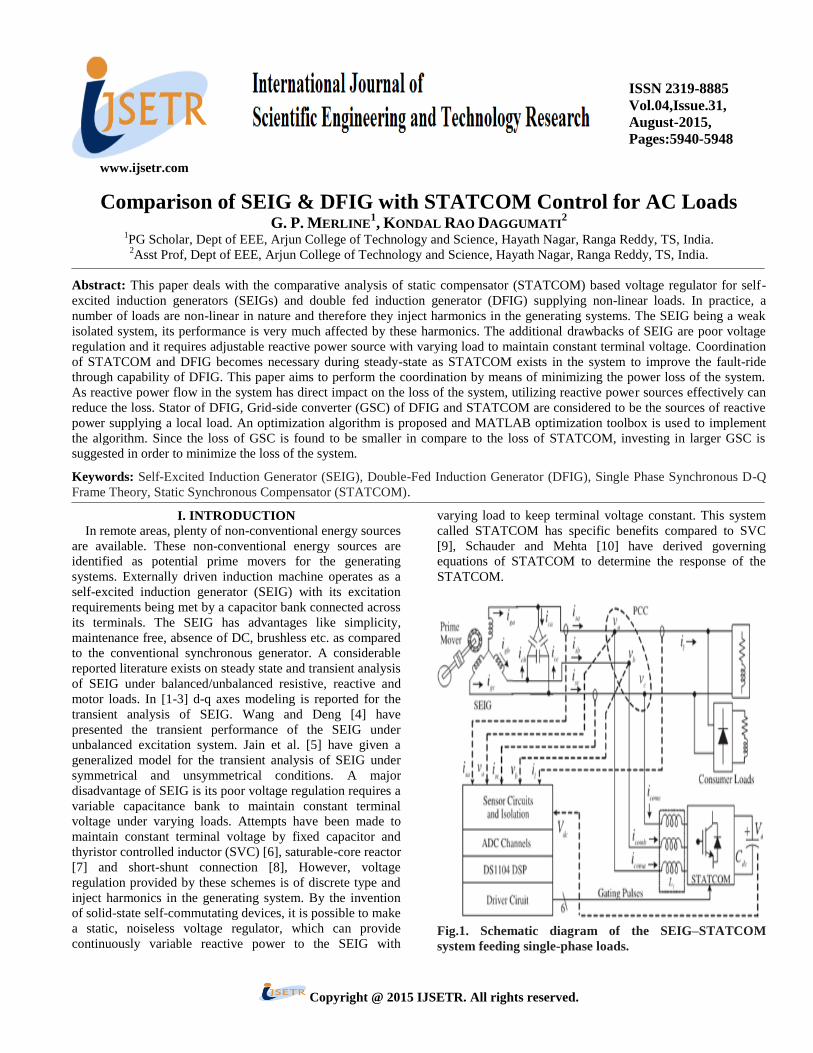
Fig.9. FFT window for source current.
Fig.10.Simulation results for active power at source side
and load side.
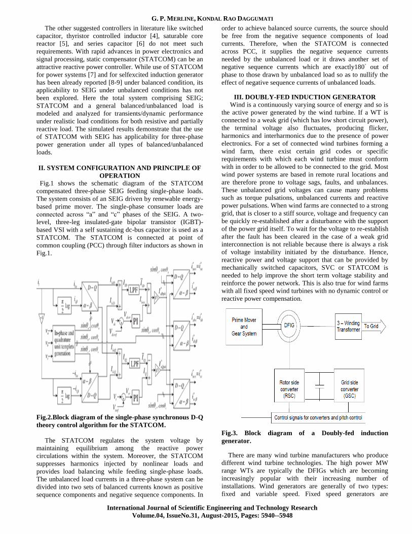
B. For Single phase non linear load
Fig.11.Simulink circuit for single phase non linear load.
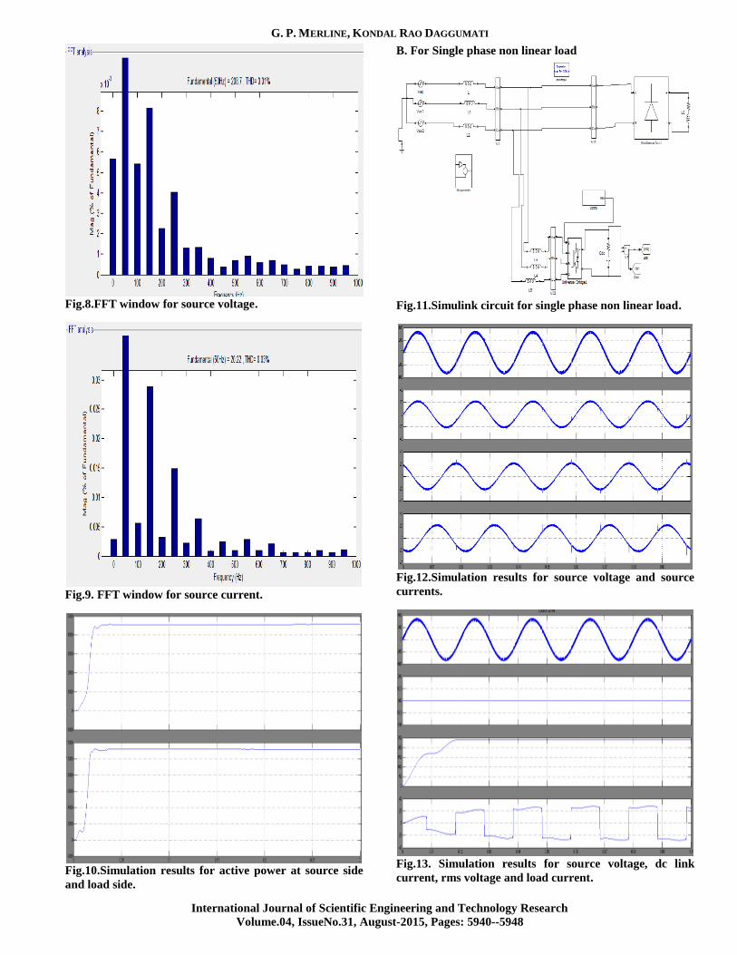
Fig.12.Simulation results for source voltage and source
currents.
Fig.13. Simulation results for source voltage, dc link
current, rms voltage and load current.
Comparison of SEIG & DFIG with STATCOM Control for AC Loads
International Journal of Scientific Engineering and Technology Research
Volume.04, IssueNo.31, August-2015, Pages: 5940-5948
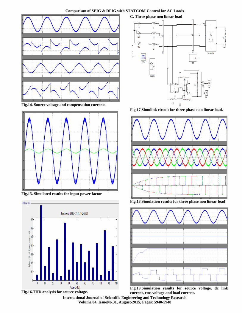
Fig.14. Source voltage and compensation currents.
Fig.15. Simulated results for input power factor
Fig.16.THD analysis for source voltage.
C. Three phase non linear load
Fig.17.Simulink circuit for three phase non linear load.
Fig.18.Simulation results for three phase non linear load
Fig.19.Simulation results for source voltage, dc link
current, rms voltage and load current.
G. P. MERLINE, KONDAL RAO DAGGUMATI
International Journal of Scientific Engineering and Technology Research
Volume.04, IssueNo.31, August-2015, Pages: 5940--5948
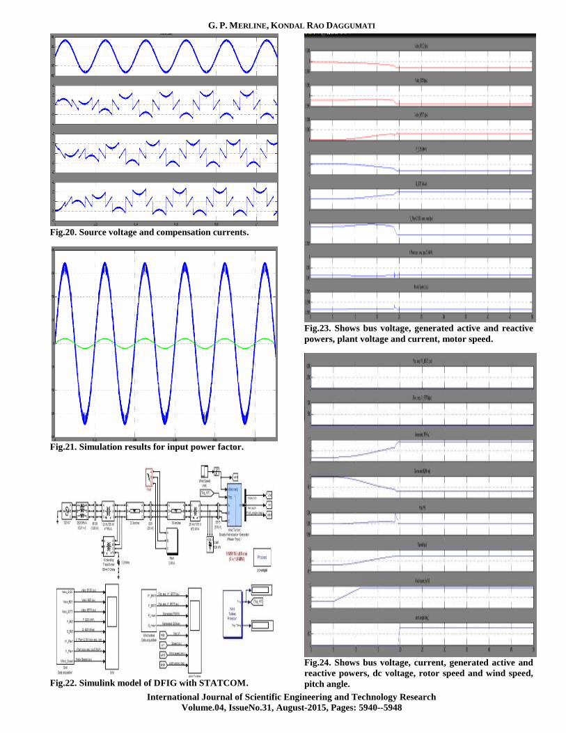
Fig.20. Source voltage and compensation currents.
Fig.21. Simulation results for input power factor.
Fig.22. Simulink model of DFIG with STATCOM.
Fig.23. Shows bus voltage, generated active and reactive
powers, plant voltage and current, motor speed.
Fig.24. Shows bus voltage, current, generated active and
reactive powers, dc voltage, rotor speed and wind speed,
pitch angle.
Comparison of SEIG & DFIG with STATCOM Control for AC Loads
International Journal of Scientific Engineering and Technology Research
Volume.04, IssueNo.31, August-2015, Pages: 5940-5948
VI. CONCLUSION
In this, a synchronization scheme for stator flux-oriented
DFIG control systems to the utility network has been
proposed. The pitch angle controller adjusts the turbine speed
at the required value for equal frequency. The stator voltage
is generated to be equal to the grid voltage by adjusting the
rotor d-axis current. The voltage phase shift is compensated
using the d-axis voltage component of both sides. The
proposed synchronization algorithm gives smooth and fast
synchronization, which enables the system to be reclosed
quickly after grid fault clearing.
VII. REFERENCES
[1] E. D. Bassett and F. M. Potter, “Capacitive excitation for
induction generators,” Trans. Amer. Inst. Elect. Eng., vol. 54,
no. 5, pp. 540–545, May 1935.
[2] J. E. Barkle and R. W. Ferguson, “Induction generator
theory and application,” Trans. Amer. Inst. Elect. Eng., vol.
73, no. 1, pp. 12–19, Jan.1954.
[3] (2013). [Online]. Available: http://www.picohydro.org.uk
[4] N. Smith Motors as Generators for Micro-Hydro Power.
London, U.K.: ITDG Publishing, 1994.
[5] S. Khennas and A. Barnett, “Best practices for sustainable
development of micro hydro power in developing countries,”
World Bank, Washington, DC, USA, ESMAP Tech. Rep.
21640, no. 6, 2000.
[6] H. Rai, A. Tandan, S. Murthy, B. Singh, and B. Singh,
“Voltage regulation of self excited induction generator using
passive elements,” inProc. IEEE Int. Conf. Elect. Mach.
Drives, Sep. 1993, pp. 240–245.
[7] L. Shridhar, B. Singh, and C. Jha, “Transient performance
of the self regulated short shunt self excited induction
generator,”IEEE Trans. Energy Convers., vol. 10, no. 2, pp.
261–267, Jun. 1995.
[8] E. Bim, J. Szajner, and Y. Burian, “Voltage
compensation of an induction generator with long-shunt
connection,” IEEE Trans. Energy Convers., vol. 4, no. 3, pp.
526–530, Sep. 1989.
[9] L. Shridhar, B. Singh, C. Jha, B. Singh, and S. Murthy,
“Selection of capacitors for the self regulated short shunt self
excited induction generator,” IEEE Trans. Energy Convers.,
vol. 10, no. 1, pp. 10–17, Mar. 1995.
[10] L. Wang and C.-H. Lee, “Long-shunt and short-shunt
connections on dynamic performance of a SEIG feeding an
induction motor load,” IEEE Trans. Energy Convers., vol.
15, no. 1, pp. 1–7, Mar. 2000.
Author’s Profile:
G.P.Merline received B.TECH degree
from Srineedhi Institute of Science and
Technology College in the year 2011 and
currently pursing M.Tech in Electrical
Power Systems at Arjun College of
Technology and Science. And his areas of
interest are Power Quality control, Hybrid
multilevel inverters and electrical circuit analyses.
Kondal Rao Daggumati presently
working as Assistant Professor in Arjun
College of Technology and Sciences.
Related Documents