E-ISSN: 2278–179X JECET; December 2013 – February 2014 Vol.3.No.1, 000-000. Journal of Environmental Science, Computer Science and Engineering & Technology An International Peer Review E-3 Journal of Sciences and Technology Available online at www.jecet.org Computer Science Research Article JECET; December 2013 – February 2014 Vol.3.No.1, 000-000. 1 Comparison of SC-FDE and OFDM Modulation Schemes for 4G Wireless Communication Systems Ale D.T. and Ogunti E.O EEE Department, Federal University of Technology Akure, Nigeria Received: 5 January 2014; Revised: 29 January 2014; Accepted: 00 January 2014 Abstract: In this paper, we have investigated the LTE-A uplink (User Equipment to eNodeB), and performed link level analysis and simulation of Single-Carrier Frequency Domain Equalization (SC-FDE) in comparison to Orthogonal Frequency Division Multiplexing (OFDM). The comparison has been done in terms of Signal to Noise Ratio (SNR), Symbol Error Rate (SER) using Zero-Forcing (ZF) and Minimum Mean Square Error (MMSE) equalization techniques, and the results show that the performances of the two techniques are similar for a frequency flat fading channel and that the use of appropriate cyclic prefix of length not less than the Doppler spread of the channel improves performance of both systems. Keywords: SC-FDM, OFDM, 4G, SINR, SNR, SER INTRODUCTION The evolution of mobile communication in the last few years has been very rapid as the system evolved from 1G to the present 4G, with data rates increasing from the order of kbps to the order of Gbps. The 4G systems (the family of Long Term Evolution, LTE) is a complete shift from the 3G system (which uses the Wideband Code Division Multiple Access, WCDMA) as it has an architecture which supports packet-switched traffic with seamless mobility, Quality of Service (QoS) and minimal latency 1 . The packet-switched approach allows for an all-IP based communication, this has resulted in a flatter architecture with only two types of nodes, namely, the evolved Node-B (eNB) and the

Welcome message from author
This document is posted to help you gain knowledge. Please leave a comment to let me know what you think about it! Share it to your friends and learn new things together.
Transcript
E-ISSN: 2278–179X
JECET; December 2013 – February 2014 Vol.3.No.1, 000-000.
Journal of Environmental Science, Computer Science and
Engineering & Technology An International Peer Review E-3 Journal of Sciences and Technology
Available online at www.jecet.org
Computer Science
Research Article
JECET; December 2013 – February 2014 Vol.3.No.1, 000-000.
1
Comparison of SC-FDE and OFDM Modulation Schemes for 4G Wireless Communication Systems
Ale D.T. and Ogunti E.O
EEE Department, Federal University of Technology Akure, Nigeria
Received: 5 January 2014; Revised: 29 January 2014; Accepted: 00 January 2014
Abstract: In this paper, we have investigated the LTE-A uplink (User Equipment to eNodeB), and performed link level analysis and simulation of Single-Carrier Frequency Domain Equalization (SC-FDE) in comparison to Orthogonal Frequency Division Multiplexing (OFDM). The comparison has been done in terms of Signal to Noise Ratio (SNR), Symbol Error Rate (SER) using Zero-Forcing (ZF) and Minimum Mean Square Error (MMSE) equalization techniques, and the results show that the performances of the two techniques are similar for a frequency flat fading channel and that the use of appropriate cyclic prefix of length not less than the Doppler spread of the channel improves performance of both systems.
Keywords: SC-FDM, OFDM, 4G, SINR, SNR, SER
INTRODUCTION
The evolution of mobile communication in the last few years has been very rapid as the system evolved from 1G to the present 4G, with data rates increasing from the order of kbps to the order of Gbps. The 4G systems (the family of Long Term Evolution, LTE) is a complete shift from the 3G system (which uses the Wideband Code Division Multiple Access, WCDMA) as it has an architecture which supports packet-switched traffic with seamless mobility, Quality of Service (QoS) and minimal latency1. The packet-switched approach allows for an all-IP based communication, this has resulted in a flatter architecture with only two types of nodes, namely, the evolved Node-B (eNB) and the
Comparison... Ale and Ogunti.
JECET; December 2013 – February 2014 Vol.3.No.1, 000-000.
2
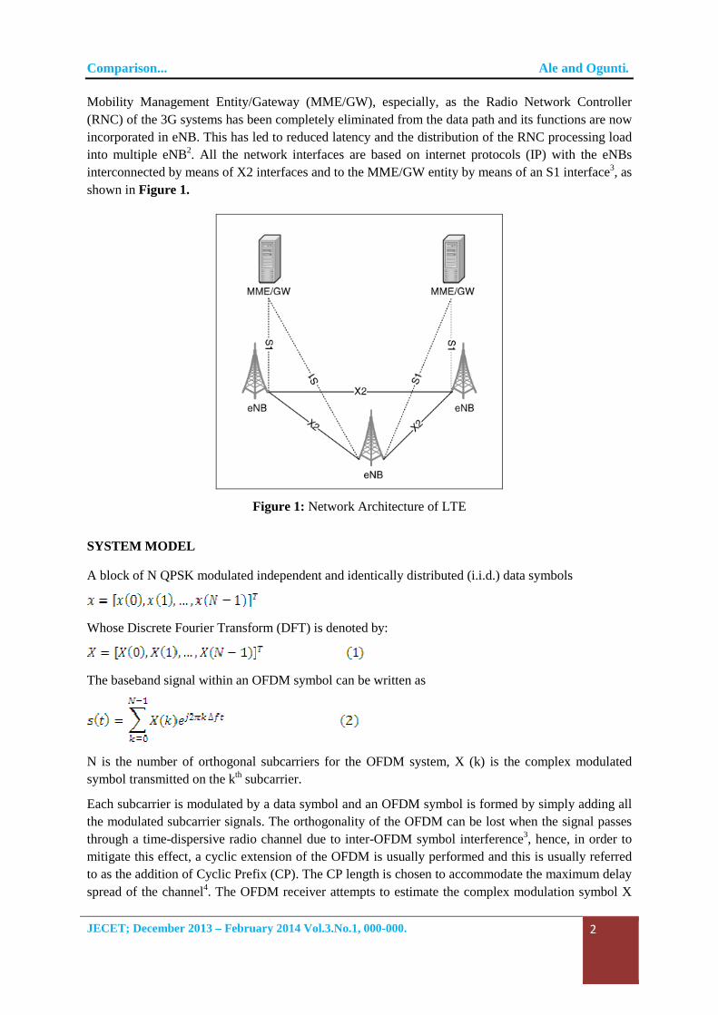
Mobility Management Entity/Gateway (MME/GW), especially, as the Radio Network Controller (RNC) of the 3G systems has been completely eliminated from the data path and its functions are now incorporated in eNB. This has led to reduced latency and the distribution of the RNC processing load into multiple eNB2. All the network interfaces are based on internet protocols (IP) with the eNBs interconnected by means of X2 interfaces and to the MME/GW entity by means of an S1 interface3, as shown in Figure 1.
Figure 1: Network Architecture of LTE
SYSTEM MODEL
A block of N QPSK modulated independent and identically distributed (i.i.d.) data symbols
Whose Discrete Fourier Transform (DFT) is denoted by:
The baseband signal within an OFDM symbol can be written as
N is the number of orthogonal subcarriers for the OFDM system, X (k) is the complex modulated symbol transmitted on the kth subcarrier.
Each subcarrier is modulated by a data symbol and an OFDM symbol is formed by simply adding all the modulated subcarrier signals. The orthogonality of the OFDM can be lost when the signal passes through a time-dispersive radio channel due to inter-OFDM symbol interference3, hence, in order to mitigate this effect, a cyclic extension of the OFDM is usually performed and this is usually referred to as the addition of Cyclic Prefix (CP). The CP length is chosen to accommodate the maximum delay spread of the channel4. The OFDM receiver attempts to estimate the complex modulation symbol X
Comparison... Ale and Ogunti.
JECET; December 2013 – February 2014 Vol.3.No.1, 000-000.
3
(m) by multiplying the received signal with and integrating over OFDM symbol duration
as shown in equation 4 and 5.
The result also holds under the assumption of perfect time and frequency synchronization and that there is no frequency and time dispersion caused by the channel.
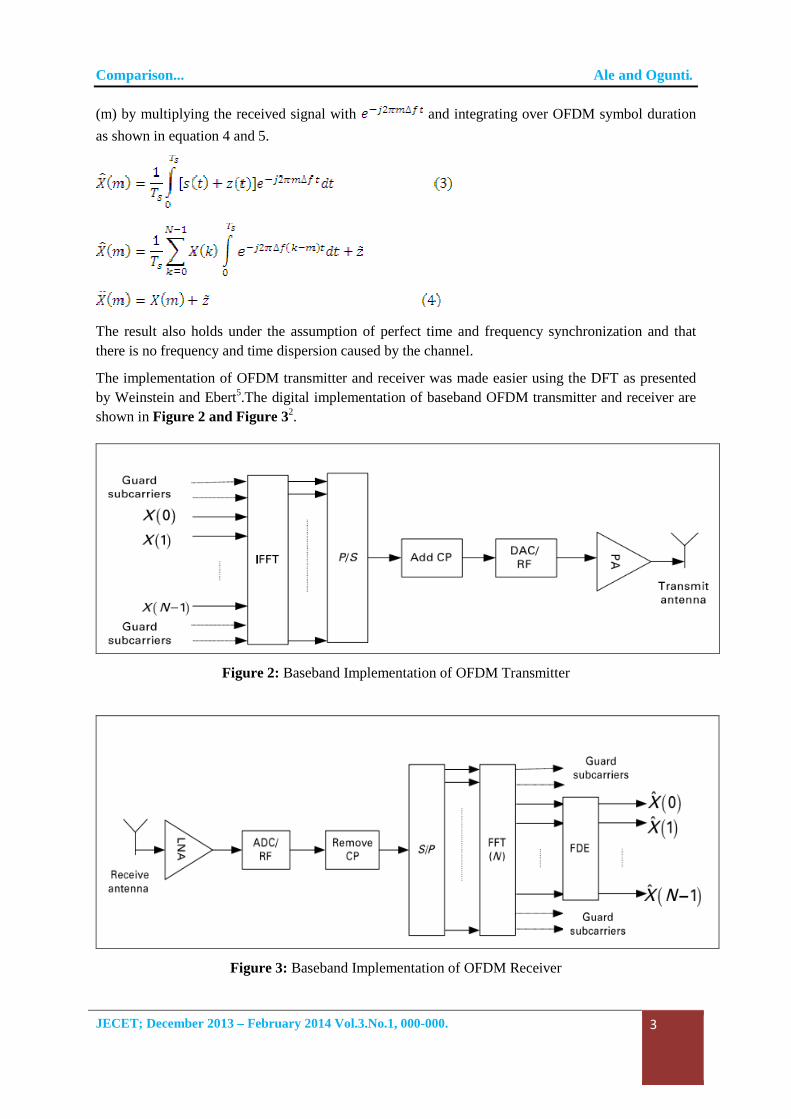
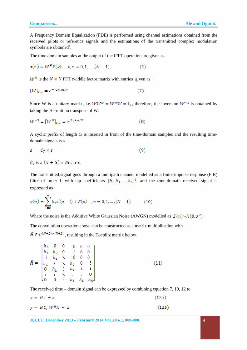
The implementation of OFDM transmitter and receiver was made easier using the DFT as presented by Weinstein and Ebert5.The digital implementation of baseband OFDM transmitter and receiver are shown in Figure 2 and Figure 32.
Figure 2: Baseband Implementation of OFDM Transmitter
Figure 3: Baseband Implementation of OFDM Receiver
Comparison... Ale and Ogunti.
JECET; December 2013 – February 2014 Vol.3.No.1, 000-000.
4
A Frequency Domain Equalization (FDE) is performed using channel estimations obtained from the received pilots or reference signals and the estimations of the transmitted complex modulation symbols are obtained6.
The time domain samples at the output of the IFFT operation are given as
is the FFT twiddle factor matrix with entries given as :
Since W is a unitary matrix, i.e. , therefore, the inversion is obtained by
taking the Hermittian transpose of W.
A cyclic prefix of length G is inserted in front of the time-domain samples and the resulting time-
domain signals is
is a matrix.
The transmitted signal goes through a multipath channel modelled as a finite impulse response (FIR) filter of order L with tap coefficients , and the time-domain received signal is
expressed as
Where the noise is the Additive White Gaussian Noise (AWGN) modelled as .
The convolution operation above can be constructed as a matrix multiplication with
, resulting in the Toeplitz matrix below.
The received time – domain signal can be expressed by combining equation 7, 10, 12 to
Comparison... Ale and Ogunti.
JECET; December 2013 – February 2014 Vol.3.No.1, 000-000.
5
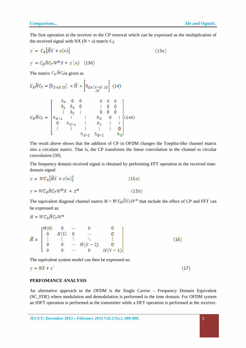
The first operation at the receiver in the CP removal which can be expressed as the multiplication of the received signal with NX (N + a) matrix
The matrix is given as
The result above shows that the addition of CP in OFDM changes the Toeplitz-like channel matrix into a circulant matrix. That is, the CP transforms the linear convolution in the channel to circular convolution [50].
The frequency domain received signal is obtained by performing FFT operation in the received time-domain signal
The equivalent diagonal channel matrix H = that include the effect of CP and FFT can
be expressed as:
The equivalent system model can then be expressed as:
PERFOMANCE ANALYSIS
An alternative approach to the OFDM is the Single Carrier – Frequency Domain Equivalent (SC_FDE) where modulation and demodulation is performed in the time domain. For OFDM system an IDFT operation is performed at the transmitter while a DFT operation is performed at the receiver.
Comparison... Ale and Ogunti.
JECET; December 2013 – February 2014 Vol.3.No.1, 000-000.
6
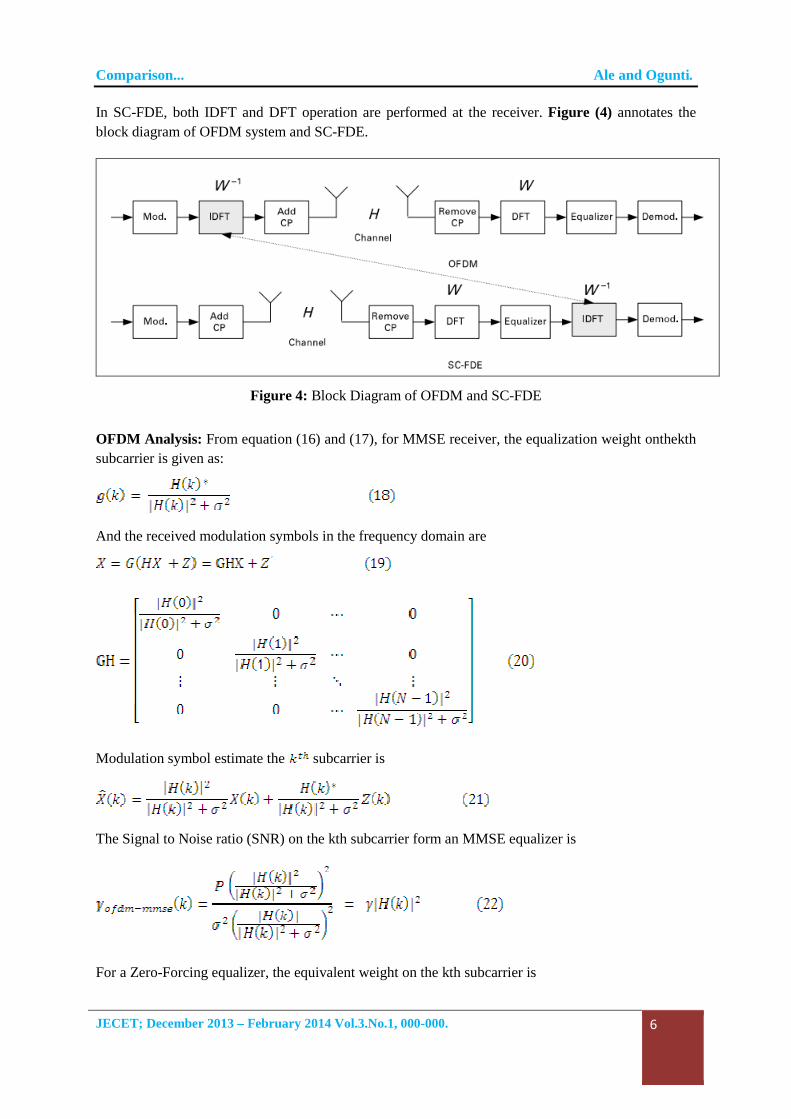
In SC-FDE, both IDFT and DFT operation are performed at the receiver. Figure (4) annotates the block diagram of OFDM system and SC-FDE.
Figure 4: Block Diagram of OFDM and SC-FDE
OFDM Analysis: From equation (16) and (17), for MMSE receiver, the equalization weight onthekth subcarrier is given as:
And the received modulation symbols in the frequency domain are
Modulation symbol estimate the subcarrier is
The Signal to Noise ratio (SNR) on the kth subcarrier form an MMSE equalizer is
For a Zero-Forcing equalizer, the equivalent weight on the kth subcarrier is
Comparison... Ale and Ogunti.
JECET; December 2013 – February 2014 Vol.3.No.1, 000-000.
7
The modulation symbol estimate is
The SNR is given as
With is the overall SNR.
SC-FDM Analysis: For SCFDE, the modulation symbols are
transmitted in the time-domain, the frequency domain symbols are
given by
The time domain symbol estimate using an MMSE equalizer is
On thorough mathematical analysis, it can be shown that the SNR
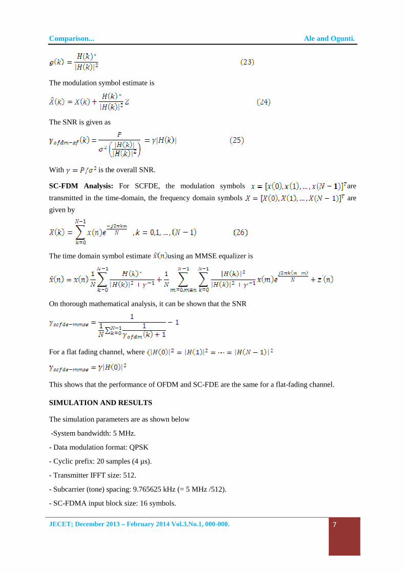
For a flat fading channel, where
This shows that the performance of OFDM and SC-FDE are the same for a flat-fading channel.
SIMULATION AND RESULTS
The simulation parameters are as shown below
-System bandwidth: 5 MHz.
- Data modulation format: QPSK
- Cyclic prefix: 20 samples (4 µs).
- Transmitter IFFT size: 512.
- Subcarrier (tone) spacing: 9.765625 kHz (= 5 MHz /512).
- SC-FDMA input block size: 16 symbols.
Comparison... Ale and Ogunti.
JECET; December 2013 – February 2014 Vol.3.No.1, 000-000.
8
- SC-FDMA input FFT size: 16.
- Channel estimation: Perfect.
- Equalization: Zero Forcing and Minimum mean Square Error (MMSE).
- Channel coding: None.
- Detection: Hard decision.
Figure 5: Flat-fading channel response for OFDM and SC-FDE
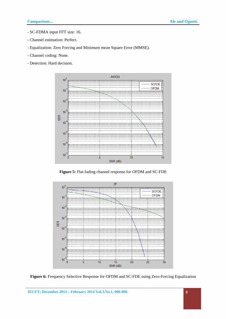
Figure 6: Frequency Selective Response for OFDM and SC-FDE using Zero-Forcing Equalization
Comparison... Ale and Ogunti.
JECET; December 2013 – February 2014 Vol.3.No.1, 000-000.
9
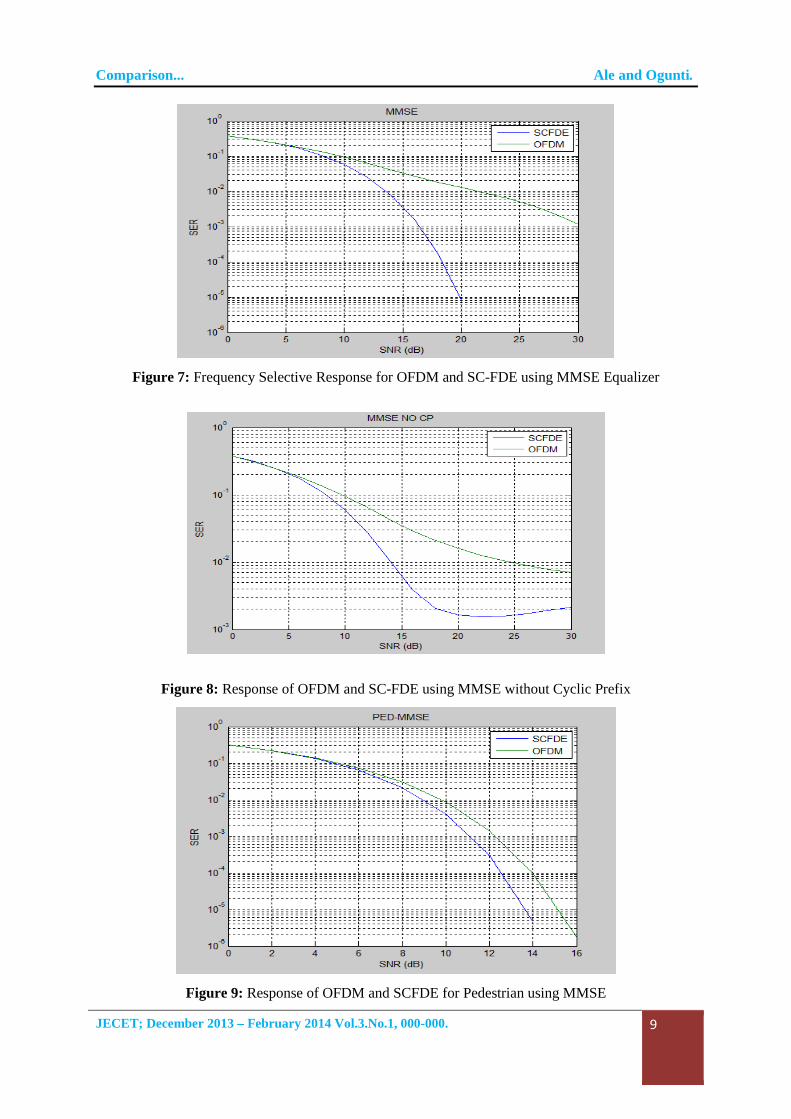
Figure 7: Frequency Selective Response for OFDM and SC-FDE using MMSE Equalizer
Figure 8: Response of OFDM and SC-FDE using MMSE without Cyclic Prefix
Figure 9: Response of OFDM and SCFDE for Pedestrian using MMSE
Comparison... Ale and Ogunti.
JECET; December 2013 – February 2014 Vol.3.No.1, 000-000.
10
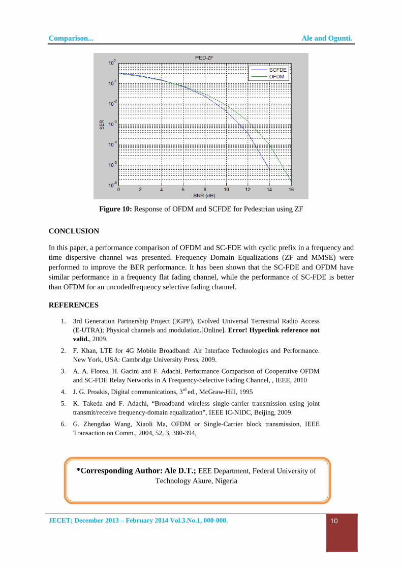
Figure 10: Response of OFDM and SCFDE for Pedestrian using ZF
CONCLUSION
In this paper, a performance comparison of OFDM and SC-FDE with cyclic prefix in a frequency and time dispersive channel was presented. Frequency Domain Equalizations (ZF and MMSE) were performed to improve the BER performance. It has been shown that the SC-FDE and OFDM have similar performance in a frequency flat fading channel, while the performance of SC-FDE is better than OFDM for an uncodedfrequency selective fading channel.
REFERENCES
1. 3rd Generation Partnership Project (3GPP), Evolved Universal Terrestrial Radio Access (E-UTRA); Physical channels and modulation.[Online]. Error! Hyperlink reference not valid., 2009.
2. F. Khan, LTE for 4G Mobile Broadband: Air Interface Technologies and Performance. New York, USA: Cambridge University Press, 2009.
3. A. A. Florea, H. Gacini and F. Adachi, Performance Comparison of Cooperative OFDM and SC-FDE Relay Networks in A Frequency-Selective Fading Channel, , IEEE, 2010
4. J. G. Proakis, Digital communications, 3rd ed., McGraw-Hill, 1995
5. K. Takeda and F. Adachi, “Broadband wireless single-carrier transmission using joint transmit/receive frequency-domain equalization”, IEEE IC-NIDC, Beijing, 2009.
6. G. Zhengdao Wang, Xiaoli Ma, OFDM or Single-Carrier block transmission, IEEE Transaction on Comm., 2004, 52, 3, 380-394,
*Corresponding Author: Ale D.T.; EEE Department, Federal University of
Technology Akure, Nigeria
Related Documents
![Proceedings - repository.ittelkom-pwt.ac.idrepository.ittelkom-pwt.ac.id/5440/1/[01 Seminar Nasional].pdf · Penemu dan sekaligus pemilik paten teknologi 4G berbasis OFDM (Orthogonal](https://static.cupdf.com/doc/110x72/6083ea37d612a85f8f096eb9/proceedings-01-seminar-nasionalpdf-penemu-dan-sekaligus-pemilik-paten-teknologi.jpg)