Comparison of Pumped and Non- Pumped SBE-41CP CTD Sensors on the Slocum Coastal Electric Glider Clayton Jones 1 , Scott Glenn 2 , John Kerfoot 2 , Oscar Schofield 2 , Dave Aragon 2 , Chip Haldeman 2 , Dave Pingal 1 1 Teledyne Webb Research Corporation, Falmouth, MA, USA

Comparison of Pumped and Non-Pumped SBE-41CP CTD Sensors on the Slocum Coastal Electric Glider Clayton Jones 1, Scott Glenn 2, John Kerfoot 2, Oscar Schofield.
Dec 21, 2015
Welcome message from author
This document is posted to help you gain knowledge. Please leave a comment to let me know what you think about it! Share it to your friends and learn new things together.
Transcript

Comparison of Pumped and Non-Pumped SBE-41CP CTD Sensors on the Slocum
Coastal Electric Glider
Clayton Jones1, Scott Glenn2, John Kerfoot2, Oscar Schofield2, Dave Aragon2, Chip Haldeman2, Dave Pingal11 Teledyne Webb Research Corporation, Falmouth, MA, USA
2 Institute of Marine & Coastal Sciences, Rutgers University, New Brunswick, NJ, USA

Slocum Coastal Electric Glider• Modular
• 3 meters in length
• Uses buoyancy to move through the water column in a saw-tooth pattern
• RF and satellite communications
• Non-pumped SBE-41CP CTD (@ 0.5Hz)• Wide variety of additional payloads
• Dissolved Oxygen• Inherent Optical Properties• Chlorophyll a• Colored Dissolved Organic Matter

CTD Types: SBE-41CP
Current: Non-Pumped Next Generation: pumped

Non-Pumped CTD: Cost/Mechanical Considerations
• Lower Power Consumption (~130mW)• Longer Duration Deployments• Requires Less Physical Space• More Space Available for Additional Sensors• Less Expensive

Pumped CTD: Cost/Mechanical Considerations
• Higher Power Consumption (~150mW @ 10mL sec-1)• Shorter Duration• Requires More Physical Space• Less Space Available for Additional Sensors• More Expensive (> 2x un-pumped)
http://www.seabird.com/pdf_documents/datasheets/GliderCTDPrelimSpec3.pdf
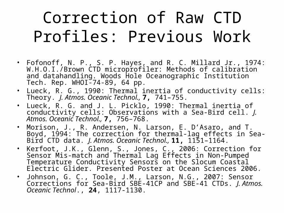
Correction of Raw CTD Profiles: Previous Work
• Fofonoff, N. P., S. P. Hayes, and R. C. Millard Jr., 1974: W.H.O.I./Brown CTD microprofiler: Methods of calibration and datahandling. Woods Hole Oceanographic Institution Tech. Rep. WHOI-74-89, 64 pp.
• Lueck, R. G., 1990: Thermal inertia of conductivity cells: Theory. J. Atmos. Oceanic Technol., 7, 741–755.
• Lueck, R. G. and J. L. Picklo, 1990: Thermal inertia of conductivity cells: Observations with a Sea-Bird cell. J. Atmos. Oceanic Technol., 7, 756–768.
• Morison, J., R. Andersen, N. Larson, E. D’Asaro, and T. Boyd, 1994: The correction for thermal-lag effects in Sea-Bird CTD data. J. Atmos. Oceanic Technol., 11, 1151–1164.
• Kerfoot, J.K., Glenn, S., Jones, C., 2006: Correction for Sensor Mis-match and Thermal Lag Effects in Non-Pumped Temperature Conductivity Sensors on the Slocum Coastal Electric Glider. Presented Poster at Ocean Sciences 2006.
• Johnson, G. C., Toole, J.M., Larson, N.G., 2007: Sensor Corrections for Sea-Bird SBE-41CP and SBE-41 CTDs. J. Atmos. Oceanic Technol., 24, 1117-1130.

RU22/RU23 Glider Deployments: September 2009
Non-pumped CTD: RU22 Segment: ru22_2009_264_1_60September 26, 2009 14:42 – September 26, 2009 17:42 GMT
Pumped CTD: RU23 Segment: ru23_2009_264_1_64September 26, 2009 23:22 – September 27, 2009 02:24 GMT
Selected segments were ~4km apart

Raw CTD SectionsNon-Pumped Pumped

Raw CTD Profiles and MeansNon-Pumped Pumped

Correction of Raw CTD Profiles: CT Sensor Mismatch
• Difficult since CT mismatch offsets are much lower than the nominal sampling frequency (0.5 Hz) of the CTD.
Temperature AlignmentComparison of ΔTemp and ΔCond on upcast and downcast – highly variable!

Correction of Raw CTD Profiles: Thermal Inertia
•Theory: Within the same water mass and in the absence of internal wave action, 2 consecutive (upcast and downcast) profiles should possess the same hydrographic (T-S) characteristics.•Select 2 consecutive profiles which do not exhibit internal wave activity. •Morison, et.al (1994):
TT(n) = -bT(n-1) + a[T(n) – T(n-1)]
a = 4fnατ/(1 + 4fnτ) and b = 1 – 2a/α
•Vary α and Τ to minimize the area of the polygon formed by joining the resulting salinity profiles.

Thermal Inertia Results: pumped CTD

Thermal Inertia Results: pumped CTD – Unsmoothed
Salinity Density N2

Thermal Inertia Results: pumped CTD - Smoothed
Salinity Density N2

Conclusions
• Glider vertical velocity and pitch are key factors in any attempt at correcting un-pumped CTD
• Vertical velocity and pitch vary significantly, depending on ballast accuracy and water column density.
• Pumped CTD provides constant flow which significantly improves success rate of correcting for thermal inertia
Related Documents