Comparison of Pratt and Whitney Rocketdyne IGCC and Commercial IGCC Performance DOE/NETL-401/062006 Final Report June 2006

Welcome message from author
This document is posted to help you gain knowledge. Please leave a comment to let me know what you think about it! Share it to your friends and learn new things together.
Transcript
Comparison of Pratt and Whitney Rocketdyne IGCC and Commercial IGCC Performance
DOE/NETL-401/062006
Final Report June 2006

Disclaimer
This report was prepared as an account of work sponsored by an agency of the United States Government. Neither the United States Government nor any agency thereof, nor any of their employees, makes any warranty, express or implied, or assumes any legal liability or responsibility for the accuracy, completeness, or usefulness of any information, apparatus, product, or process disclosed, or represents that its use would not infringe privately owned rights. Reference therein to any specific commercial product, process, or service by trade name, trademark, manufacturer, or otherwise does not necessarily constitute or imply its endorsement, recommendation, or favoring by the United States Government or any agency thereof. The views and opinions of authors expressed therein do not necessarily state or reflect those of the United States Government or any agency thereof.

Comparison of Pratt and Whitney Rocketdyne IGCC and Commercial IGCC Performance
DOE/NETL-401/062006
Final Report
June 2006
NETL Contact:
Jeffrey Hoffmann Office of Systems Analysis and Planning
Jenny Tennant Gasification & Combustion Projects Division
Gary J. Stiegel Gasification Technology Manager
Office of Coal and Power Research and Development
Prepared by:
Research and Development Solutions, LLC (RDS)
Michael Matuszewski, Parsons Corporation Michael D. Rutkowski, Parsons Corporation
Ronald L. Schoff, Parsons Corporation
National Energy Technology Laboratory www.netl.doe.gov

This page intentionally left blank
Comparison of Pratt and Whitney Rocketdyne IGCC and Commercial IGCC Performance
TABLE OF CONTENTS List of Exhibits .............................................................................................................................. ii List of Acronyms and Abbreviations ......................................................................................... iv Executive Summary.......................................................................................................................1 1 Design Basis ........................................................................................................................5 1.1 Site Characteristics...............................................................................................................5 1.2 Environmental Constraints...................................................................................................6 2 Case 1 - PWR Gasifier Based IGCC Plant Description and Results ............................9 2.1 Process Description..............................................................................................................9 2.2 Modeling Assumptions for PWR Gasifier.........................................................................10 2.3 Equipment Descriptions.....................................................................................................16 2.4 Performance Results ..........................................................................................................19 2.5 Economic Results...............................................................................................................20 3 Case 2 - GE Energy Gasifier Based IGCC Plant Description and Results.................25 3.1 Process Description............................................................................................................25 3.2 Equipment Descriptions.....................................................................................................29 3.3 Performance Results ..........................................................................................................30 3.4 Economic Results...............................................................................................................31 4 Case 3 - PWR Gasifier Based IGCC Plant Description and Results ..........................37 4.1 Process Description............................................................................................................37 4.2 Modeling Assumptions for PWR Gasifier.........................................................................38 4.3 Equipment Descriptions.....................................................................................................42 4.4 Performance Results ..........................................................................................................45 4.5 Economic Results...............................................................................................................46 5 Case 4 - Shell Gasifier Based IGCC Plant Description and Results ...........................51 5.1 Process Description............................................................................................................51 5.2 Equipment Descriptions.....................................................................................................56 5.3 Performance Results ..........................................................................................................58 5.4 Economic Results...............................................................................................................59 6 Case 5 - PWR Gasifier Based H2 Production Plant Description and Results ............65 6.1 Process Description............................................................................................................65 6.2 Modeling Assumptions for PWR Gasifier.........................................................................65 6.3 Equipment Descriptions.....................................................................................................69 6.4 Performance Results ..........................................................................................................72 6.5 Economic Results...............................................................................................................73 7 Case 6 - GE Energy Gasifier Based H2 Production Plant Description and
Results ...............................................................................................................................79 7.1 Process Description............................................................................................................79 7.2 Equipment Descriptions.....................................................................................................83 7.3 Performance Results ..........................................................................................................86 7.4 Economic Results...............................................................................................................87 8 Summary...........................................................................................................................93 9 References.........................................................................................................................96
Final Report i June 2006
Comparison of Pratt and Whitney Rocketdyne IGCC and Commercial IGCC Performance
LIST OF EXHIBITS Exhibit 1 Plant Configuration Summary......................................................................................... 1 Exhibit 2 Performance Summary and Economic Analysis Results ................................................ 2 Exhibit 3 Plant Configuration Summary......................................................................................... 5 Exhibit 4 Site Ambient Conditions................................................................................................. 5 Exhibit 5 Site Characteristics.......................................................................................................... 6 Exhibit 6 Design Coal Characteristics ............................................................................................ 6 Exhibit 7 NSPS Emission Requirements Summary........................................................................ 7 Exhibit 8 Best Available Control Technology Determinations by Technology ............................. 8 Exhibit 9 Case 1 - PWR IGCC Plant Block Flow Diagram ......................................................... 13 Exhibit 10 Case 1 - PWR IGCC Plant Stream Table.................................................................... 14 Exhibit 11 Case 1 - PWR IGCC Plant Performance Summary .................................................... 20 Exhibit 12 Case 1 - PWR IGCC Total Plant Capital Costs .......................................................... 21 Exhibit 13 Case 1 - PWR IGCC Capital Investment & Operating Cost Requirement Summary
(94% Capacity factor)............................................................................................................ 22 Exhibit 14 Case 1 - PWR IGCC Capital Investment & Operating Cost Requirement Summary
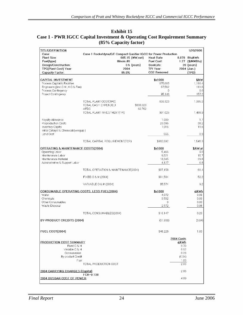
(90% Capacity factor)............................................................................................................ 23 Exhibit 15 Case 1 - PWR IGCC Capital Investment & Operating Cost Requirement Summary
(85% Capacity factor)............................................................................................................ 24 Exhibit 16 Case 2 - GE Energy IGCC Plant Block Flow Diagram .............................................. 26 Exhibit 17 Case 2 - GE Energy IGCC Plant Stream Table........................................................... 27 Exhibit 18 Case 2 - GE Energy IGCC Plant Performance Summary ........................................... 31 Exhibit 19 Case 2 - GE Energy IGCC Total Plant Capital Costs with a Dual Gasifier Train...... 32 Exhibit 20 Case 2 - GE Energy IGCC Total Plant Capital Costs with a Redundant Gasifier Train
............................................................................................................................................... 33 Exhibit 21 Case 2 - GE Energy IGCC Capital Investment & Operating Cost Requirement
Summary (94% Capacity factor) ........................................................................................... 34 Exhibit 22 Case 2 - GE Energy IGCC Capital Investment & Operating Cost Requirement
Summary (90% Capacity factor) ........................................................................................... 35 Exhibit 23 Case 2 - GE Energy IGCC Capital Investment & Operating Cost Requirement
Summary (85% Capacity factor) ........................................................................................... 36 Exhibit 24 Case 3 - PWR Convective IGCC Plant Block Flow Diagram .................................... 39 Exhibit 25 Case 3 - PWR Convective IGCC Plant Stream Table................................................. 40 Exhibit 26 Case 3 - PWR Convective IGCC Plant Performance Summary ................................. 46 Exhibit 27 Case 3 - PWR Convective IGCC Total Plant Capital Costs ....................................... 47 Exhibit 28 Case 3 - PWR Convective IGCC Capital Investment & Operating Cost Requirement
Summary (94% Capacity factor) ........................................................................................... 48 Exhibit 29 Case 3 - PWR Convective IGCC Capital Investment & Operating Cost Requirement
Summary (90% Capacity factor) ........................................................................................... 49 Exhibit 30 Case 3 - PWR Convective IGCC Capital Investment & Operating Cost Requirement
Summary (85% Capacity factor) ........................................................................................... 50 Exhibit 31 Case 4 - Shell Gasifier-Based IGCC Plant Block Flow Diagram............................... 53 Exhibit 32 Case 4 - Shell Gasifier-Based IGCC Plant Stream Table ........................................... 54 Exhibit 33 Case 4 - Shell Gasifier-Based IGCC Plant Performance Summary............................ 59
Final Report ii June 2006
Comparison of Pratt and Whitney Rocketdyne IGCC and Commercial IGCC Performance
Exhibit 34 Case 4 - Shell Gasifier-Based IGCC Total Plant Capital Costs with Dual Gasifier Train ...................................................................................................................................... 60
Exhibit 35 Case 4 - Shell Gasifier-Based IGCC Total Plant Capital Costs with Redundant Gasifier Train......................................................................................................................... 61
Exhibit 36 Case 4 - Shell Gasifier-Based IGCC Capital Investment & Operating Cost Requirement Summary (94% Capacity factor) ..................................................................... 62
Exhibit 37 Case 4 - Shell Gasifier-Based IGCC Capital Investment & Operating Cost Requirement Summary (90% Capacity factor) ..................................................................... 63
Exhibit 38 Case 4 - Shell Gasifier-Based IGCC Capital Investment & Operating Cost Requirement Summary (85% Capacity factor) ..................................................................... 64
Exhibit 39 Case 5 - PWR H2 Production Plant Block Flow Diagram .......................................... 66 Exhibit 40 Case 5 - PWR H2 Production Plant Stream Table....................................................... 67 Exhibit 41 Case 5 - PWR H2 Production Plant Performance Summary ....................................... 72 Exhibit 42 Case 5 - PWR H2 Production Total Plant Capital Costs ............................................. 74 Exhibit 43 Case 5 - PWR H2 Production Plant Capital Investment & Operating Cost Requirement
Summary (94% Capacity factor) ........................................................................................... 75 Exhibit 44 Case 5 - PWR H2 Production Plant Capital Investment & Operating Cost Requirement
Summary (90% Capacity factor) ........................................................................................... 76 Exhibit 45 Case 5 - PWR H2 Production Plant Capital Investment & Operating Cost Requirement
Summary (85% Capacity factor) ........................................................................................... 77 Exhibit 46 Case 6 - GE Energy H2 Production Plant Block Flow Diagram................................. 80 Exhibit 47 Case 6 - GE Energy H2 Production Plant Stream Table ............................................. 81 Exhibit 48 Case 6 - GE Energy H2 Production Plant Performance Summary.............................. 87 Exhibit 49 Case 6 - GE Energy H2 Production Total Plant Capital Costs with Dual Gasifier Train
............................................................................................................................................... 88 Exhibit 50 Case 6 - GE Energy H2 Production Total Plant Capital Costs with Redundant Gasifier
Train ...................................................................................................................................... 89 Exhibit 51 Case 6 - GE Energy H2 Production Plant Capital Investment & Operating Cost
Requirement Summary (94% Capacity factor) ..................................................................... 90 Exhibit 52 Case 6 - GE Energy H2 Production Plant Capital Investment & Operating Cost
Requirement Summary (90% Capacity factor) ..................................................................... 91 Exhibit 53 Case 6 - GE Energy H2 Production Plant Capital Investment & Operating Cost
Requirement Summary (85% Capacity factor) ..................................................................... 92 Exhibit 54 Performance Summary and Economic Analysis Results ............................................ 95
Final Report iii June 2006
Comparison of Pratt and Whitney Rocketdyne IGCC and Commercial IGCC Performance
LIST OF ACRONYMS AND ABBREVIATIONS acfm Actual cubic feet per minute AGR Acid Gas Removal ASU Air Separation Unit BACT/RACT Best/Reasonably available control technology CFR Code of Federal Regulations COS Carbonyl Sulfide DCS Distributed Control System DOE Department of Energy EPRI Electric Power Research Institute ERC Emission Reduction Credits FGD Flue gas desulfurization GEE General Electric Energy HHV Higher heating value HP High Pressure HRSG Heat Recovery Steam Generator IGCC Integrated Gasifier Combined Cycle kWe Kilowatt Electrical kWh Kilowatt hour kWt Kilowatt Thermal LAER Lowest achievable emission rate LCOE Levelized Cost of Electricity lb/hr pound per hour LHV Lower heating value LNB Low NOx Burner LP Low Pressure MDEA Methyldiethanolamine MMBtu Million British thermal unit MMlb Million pounds MWe Megawatt Electrical MWh Megawatt hour MWt Megawatt Thermal NGCC Natural gas combined cycle NOx Oxides of nitrogen NSPS New Source Performance Standards NSR New Source Review ppmvd Parts per million volume, dry PRB Powder River Basin psia Pounds per square inch absolute PWR Pratt & Whitney Rocketdyne SCR Selective catalytic reduction SOx Oxides of sulfur TGTU Tail gas treating unit TPC Total Plant Cost tpd tons per day WGS Water Gas Shift
Final Report iv June 2006
Comparison of Pratt and Whitney Rocketdyne IGCC and Commercial IGCC Performance
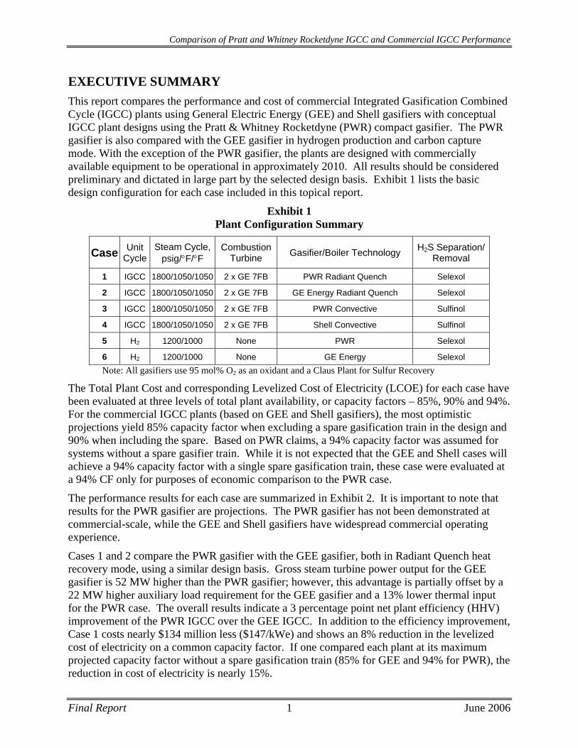
EXECUTIVE SUMMARY This report compares the performance and cost of commercial Integrated Gasification Combined Cycle (IGCC) plants using General Electric Energy (GEE) and Shell gasifiers with conceptual IGCC plant designs using the Pratt & Whitney Rocketdyne (PWR) compact gasifier. The PWR gasifier is also compared with the GEE gasifier in hydrogen production and carbon capture mode. With the exception of the PWR gasifier, the plants are designed with commercially available equipment to be operational in approximately 2010. All results should be considered preliminary and dictated in large part by the selected design basis. Exhibit 1 lists the basic design configuration for each case included in this topical report.
Exhibit 1 Plant Configuration Summary
Case Unit Cycle
Steam Cycle, psig/°F/°F
Combustion Turbine Gasifier/Boiler Technology H2S Separation/
Removal
1 IGCC 1800/1050/1050 2 x GE 7FB PWR Radiant Quench Selexol
2 IGCC 1800/1050/1050 2 x GE 7FB GE Energy Radiant Quench Selexol
3 IGCC 1800/1050/1050 2 x GE 7FB PWR Convective Sulfinol
4 IGCC 1800/1050/1050 2 x GE 7FB Shell Convective Sulfinol
5 H2 1200/1000 None PWR Selexol
6 H2 1200/1000 None GE Energy Selexol Note: All gasifiers use 95 mol% O2 as an oxidant and a Claus Plant for Sulfur Recovery
The Total Plant Cost and corresponding Levelized Cost of Electricity (LCOE) for each case have been evaluated at three levels of total plant availability, or capacity factors – 85%, 90% and 94%. For the commercial IGCC plants (based on GEE and Shell gasifiers), the most optimistic projections yield 85% capacity factor when excluding a spare gasification train in the design and 90% when including the spare. Based on PWR claims, a 94% capacity factor was assumed for systems without a spare gasifier train. While it is not expected that the GEE and Shell cases will achieve a 94% capacity factor with a single spare gasification train, these case were evaluated at a 94% CF only for purposes of economic comparison to the PWR case.
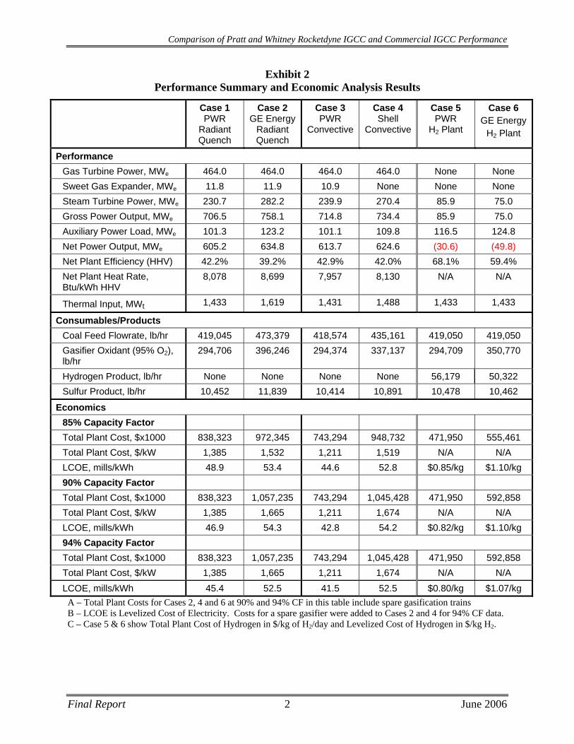
The performance results for each case are summarized in Exhibit 2. It is important to note that results for the PWR gasifier are projections. The PWR gasifier has not been demonstrated at commercial-scale, while the GEE and Shell gasifiers have widespread commercial operating experience.
Cases 1 and 2 compare the PWR gasifier with the GEE gasifier, both in Radiant Quench heat recovery mode, using a similar design basis. Gross steam turbine power output for the GEE gasifier is 52 MW higher than the PWR gasifier; however, this advantage is partially offset by a 22 MW higher auxiliary load requirement for the GEE gasifier and a 13% lower thermal input for the PWR case. The overall results indicate a 3 percentage point net plant efficiency (HHV) improvement of the PWR IGCC over the GEE IGCC. In addition to the efficiency improvement, Case 1 costs nearly $134 million less ($147/kWe) and shows an 8% reduction in the levelized cost of electricity on a common capacity factor. If one compared each plant at its maximum projected capacity factor without a spare gasification train (85% for GEE and 94% for PWR), the reduction in cost of electricity is nearly 15%.
Final Report 1 June 2006
Comparison of Pratt and Whitney Rocketdyne IGCC and Commercial IGCC Performance
Exhibit 2 Performance Summary and Economic Analysis Results
Case 1 PWR
Radiant Quench
Case 2 GE Energy
Radiant Quench
Case 3 PWR
Convective
Case 4 Shell
Convective
Case 5 PWR
H2 Plant
Case 6 GE Energy
H2 Plant
Performance Gas Turbine Power, MWe 464.0 464.0 464.0 464.0 None None Sweet Gas Expander, MWe 11.8 11.9 10.9 None None None Steam Turbine Power, MWe 230.7 282.2 239.9 270.4 85.9 75.0 Gross Power Output, MWe 706.5 758.1 714.8 734.4 85.9 75.0 Auxiliary Power Load, MWe 101.3 123.2 101.1 109.8 116.5 124.8 Net Power Output, MWe 605.2 634.8 613.7 624.6 (30.6) (49.8) Net Plant Efficiency (HHV) 42.2% 39.2% 42.9% 42.0% 68.1% 59.4% Net Plant Heat Rate, Btu/kWh HHV
8,078 8,699 7,957 8,130 N/A N/A
Thermal Input, MWt 1,433 1,619 1,431 1,488 1,433 1,433
Consumables/Products Coal Feed Flowrate, lb/hr 419,045 473,379 418,574 435,161 419,050 419,050 Gasifier Oxidant (95% O2), lb/hr
294,706 396,246 294,374 337,137 294,709 350,770
Hydrogen Product, lb/hr None None None None 56,179 50,322 Sulfur Product, lb/hr 10,452 11,839 10,414 10,891 10,478 10,462
Economics 85% Capacity Factor Total Plant Cost, $x1000 838,323 972,345 743,294 948,732 471,950 555,461 Total Plant Cost, $/kW 1,385 1,532 1,211 1,519 N/A N/A LCOE, mills/kWh 48.9 53.4 44.6 52.8 $0.85/kg $1.10/kg 90% Capacity Factor Total Plant Cost, $x1000 838,323 1,057,235 743,294 1,045,428 471,950 592,858 Total Plant Cost, $/kW 1,385 1,665 1,211 1,674 N/A N/A LCOE, mills/kWh 46.9 54.3 42.8 54.2 $0.82/kg $1.10/kg 94% Capacity Factor Total Plant Cost, $x1000 838,323 1,057,235 743,294 1,045,428 471,950 592,858 Total Plant Cost, $/kW 1,385 1,665 1,211 1,674 N/A N/A LCOE, mills/kWh 45.4 52.5 41.5 52.5 $0.80/kg $1.07/kg
A – Total Plant Costs for Cases 2, 4 and 6 at 90% and 94% CF in this table include spare gasification trains B – LCOE is Levelized Cost of Electricity. Costs for a spare gasifier were added to Cases 2 and 4 for 94% CF data. C – Case 5 & 6 show Total Plant Cost of Hydrogen in $/kg of H2/day and Levelized Cost of Hydrogen in $/kg H2.
Final Report 2 June 2006
Comparison of Pratt and Whitney Rocketdyne IGCC and Commercial IGCC Performance
Cases 3 and 4 were designed to compare the PWR Gasifier with the Shell Gasifier, both in syngas quench/convective syngas cooler heat recovery mode, using a similar design basis. Gross steam turbine power output for the Shell Gasifier is 30 MW higher than the PWR Gasifier; however, this advantage is partially offset by a 9 MW higher auxiliary load requirement for the Shell Gasifier and a 4% lower thermal input for the PWR case. The result is a nominal 1 percentage point net plant efficiency (HHV) gain for the PWR IGCC over the Shell IGCC. In addition, there is a projected $206 million ($308/kWe) reduction in total plant cost for the PWR plant. This is primarily attributable to incorporating a less expensive gasifier and syngas cooling system in addition to a reduction in coal handling, preparation and feed costs associated with using a proprietary dry coal feed pump, currently under development at PWR, instead of a conventional lock hopper system. The PWR process shows a 15% and 20% reduction in the levelized cost of electricity for a capacity factor of 85% and 94%, respectively.
Cases 5 and 6 were designed to compare the PWR Gasifier with the GE Energy Gasifier, both in hydrogen production with ~90% carbon capture mode, using a similar design basis. With each design processing 419,050 lb/hr of coal, the overall hydrogen production rate for the GE Energy gasifier is 50,322 lb/hr hydrogen, while the hydrogen production rate for the PWR gasifier is 56,179 lb/hr. Another disadvantage in the GEE design is that it requires 50 MWe input in order to operate at the stated production, while the PWR design requires only 31 MWe for its respective hydrogen production. Power requirements for both cases include the supplemental power generation of each plant. Case 5 costs more than $83 million less and shows a 23% reduction in the levelized cost of hydrogen on a common capacity factor.
PWR gasifier performance predictions are based on a proprietary one-dimensional kinetic model validated with experimental data from earlier PWR work with coal-fired systems in the areas of hydrogasification-liquefaction, steam/oxygen gasification, magnetohydrodynamic (MHD) power, acetylene production, and low NOx/SOx combustion.[1,2,3,4] Carbon conversion predictions from the one-dimensional kinetic model have been anchored to a limited amount of experimental kinetics data. Future pilot plant gasifier tests will provide a means to vary process parameters (reactant flow rates and conditions, reactor length, residence times, and pressures) and monitor results (carbon conversion, syngas composition, and heat losses) to further validate model kinetics.
Performance results for the PWR gasifier were based on methodology provided to RDS by PWR for the NASA code, “Chemical Equilibrium for Analysis”. Details are provided in the following sections of this report. Non-idealities that can occur in either pilot scale or commercial scale reactors are not accounted for by this method, which assumes 100% carbon conversion based on ideal mixing, even temperature distribution and a high coal particle heat rate. These assumptions must be verified in pilot and commercial scale demonstrations before one can conclude that the performance of the PWR Gasifier is an improvement over either GE or Shell, whose gasifiers have been widely demonstrated commercially.
Final Report 3 June 2006
Comparison of Pratt and Whitney Rocketdyne IGCC and Commercial IGCC Performance
This page intentionally left blank
Final Report 4 June 2006
Comparison of Pratt and Whitney Rocketdyne IGCC and Commercial IGCC Performance
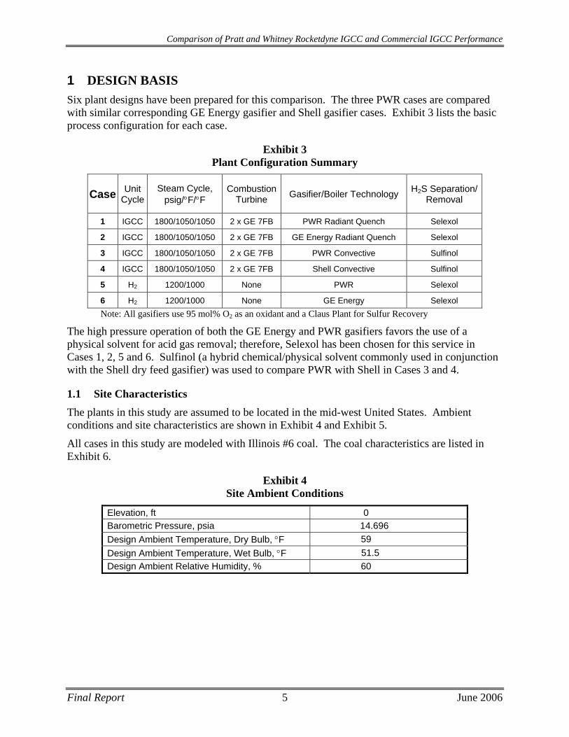
1 DESIGN BASIS Six plant designs have been prepared for this comparison. The three PWR cases are compared with similar corresponding GE Energy gasifier and Shell gasifier cases. Exhibit 3 lists the basic process configuration for each case.
Exhibit 3 Plant Configuration Summary
Case Unit Cycle
Steam Cycle, psig/°F/°F
Combustion Turbine Gasifier/Boiler Technology H2S Separation/
Removal
1 IGCC 1800/1050/1050 2 x GE 7FB PWR Radiant Quench Selexol
2 IGCC 1800/1050/1050 2 x GE 7FB GE Energy Radiant Quench Selexol
3 IGCC 1800/1050/1050 2 x GE 7FB PWR Convective Sulfinol
4 IGCC 1800/1050/1050 2 x GE 7FB Shell Convective Sulfinol
5 H2 1200/1000 None PWR Selexol
6 H2 1200/1000 None GE Energy Selexol Note: All gasifiers use 95 mol% O2 as an oxidant and a Claus Plant for Sulfur Recovery
The high pressure operation of both the GE Energy and PWR gasifiers favors the use of a physical solvent for acid gas removal; therefore, Selexol has been chosen for this service in Cases 1, 2, 5 and 6. Sulfinol (a hybrid chemical/physical solvent commonly used in conjunction with the Shell dry feed gasifier) was used to compare PWR with Shell in Cases 3 and 4.
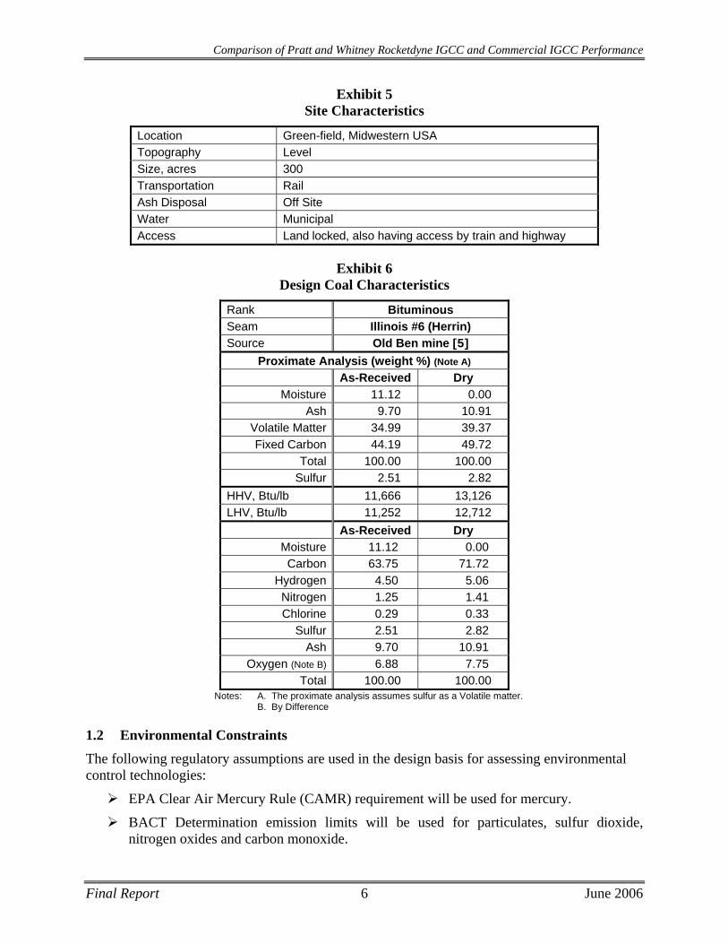
1.1 Site Characteristics The plants in this study are assumed to be located in the mid-west United States. Ambient conditions and site characteristics are shown in Exhibit 4 and Exhibit 5.
All cases in this study are modeled with Illinois #6 coal. The coal characteristics are listed in Exhibit 6.
Exhibit 4 Site Ambient Conditions
Elevation, ft 0 Barometric Pressure, psia 14.696 Design Ambient Temperature, Dry Bulb, °F 59 Design Ambient Temperature, Wet Bulb, °F 51.5 Design Ambient Relative Humidity, % 60
Final Report 5 June 2006
Comparison of Pratt and Whitney Rocketdyne IGCC and Commercial IGCC Performance
Exhibit 5 Site Characteristics
Location Green-field, Midwestern USA Topography Level Size, acres 300 Transportation Rail Ash Disposal Off Site Water Municipal Access Land locked, also having access by train and highway
Exhibit 6 Design Coal Characteristics
Rank Bituminous Seam Illinois #6 (Herrin) Source Old Ben mine [5]
Proximate Analysis (weight %) (Note A) As-Received Dry
Moisture 11.12 0.00 Ash 9.70 10.91
Volatile Matter 34.99 39.37 Fixed Carbon 44.19 49.72
Total 100.00 100.00 Sulfur 2.51 2.82
HHV, Btu/lb 11,666 13,126 LHV, Btu/lb 11,252 12,712 As-Received Dry
Moisture 11.12 0.00 Carbon 63.75 71.72
Hydrogen 4.50 5.06 Nitrogen 1.25 1.41 Chlorine 0.29 0.33
Sulfur 2.51 2.82 Ash 9.70 10.91
Oxygen (Note B) 6.88 7.75 Total 100.00 100.00
Notes: A. The proximate analysis assumes sulfur as a Volatile matter. B. By Difference
1.2 Environmental Constraints The following regulatory assumptions are used in the design basis for assessing environmental control technologies:
EPA Clear Air Mercury Rule (CAMR) requirement will be used for mercury.
BACT Determination emission limits will be used for particulates, sulfur dioxide, nitrogen oxides and carbon monoxide.
Final Report 6 June 2006
Comparison of Pratt and Whitney Rocketdyne IGCC and Commercial IGCC Performance
NOx Emission Reduction Credits (ERCs) and allowances are not available for the project emission requirements.
Solid waste disposal is either offsite at a fixed $/ton fee or is classified as a byproduct for reuse, claiming no net revenue ($/ton) or cost.
Raw water is available to meet technology needs.
Wastewater discharge will meet effluent guidelines rather than water quality standards for this screening.
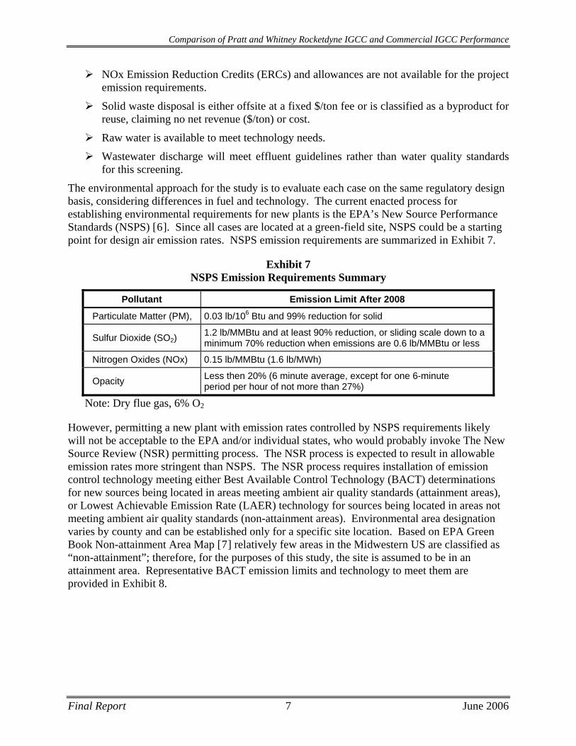
The environmental approach for the study is to evaluate each case on the same regulatory design basis, considering differences in fuel and technology. The current enacted process for establishing environmental requirements for new plants is the EPA’s New Source Performance Standards (NSPS) [6]. Since all cases are located at a green-field site, NSPS could be a starting point for design air emission rates. NSPS emission requirements are summarized in Exhibit 7.
Exhibit 7 NSPS Emission Requirements Summary
Pollutant Emission Limit After 2008
Particulate Matter (PM), 0.03 lb/106 Btu and 99% reduction for solid
Sulfur Dioxide (SO2) 1.2 lb/MMBtu and at least 90% reduction, or sliding scale down to a minimum 70% reduction when emissions are 0.6 lb/MMBtu or less
Nitrogen Oxides (NOx) 0.15 lb/MMBtu (1.6 lb/MWh)
Opacity Less then 20% (6 minute average, except for one 6-minute period per hour of not more than 27%)
Note: Dry flue gas, 6% O2
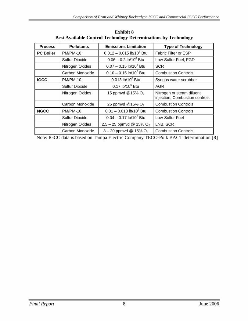
However, permitting a new plant with emission rates controlled by NSPS requirements likely will not be acceptable to the EPA and/or individual states, who would probably invoke The New Source Review (NSR) permitting process. The NSR process is expected to result in allowable emission rates more stringent than NSPS. The NSR process requires installation of emission control technology meeting either Best Available Control Technology (BACT) determinations for new sources being located in areas meeting ambient air quality standards (attainment areas), or Lowest Achievable Emission Rate (LAER) technology for sources being located in areas not meeting ambient air quality standards (non-attainment areas). Environmental area designation varies by county and can be established only for a specific site location. Based on EPA Green Book Non-attainment Area Map [7] relatively few areas in the Midwestern US are classified as “non-attainment”; therefore, for the purposes of this study, the site is assumed to be in an attainment area. Representative BACT emission limits and technology to meet them are provided in Exhibit 8.
Final Report 7 June 2006
Comparison of Pratt and Whitney Rocketdyne IGCC and Commercial IGCC Performance
Exhibit 8 Best Available Control Technology Determinations by Technology
Process Pollutants Emissions Limitation Type of Technology PC Boiler PM/PM-10 0.012 – 0.015 lb/106 Btu Fabric Filter or ESP Sulfur Dioxide 0.06 – 0.2 lb/106 Btu Low-Sulfur Fuel, FGD Nitrogen Oxides 0.07 – 0.15 lb/106 Btu SCR Carbon Monoxide 0.10 – 0.15 lb/106 Btu Combustion Controls
IGCC PM/PM-10 0.013 lb/106 Btu Syngas water scrubber Sulfur Dioxide 0.17 lb/106 Btu AGR Nitrogen Oxides 15 ppmvd @15% O2 Nitrogen or steam diluent
injection, Combustion controls Carbon Monoxide 25 ppmvd @15% O2 Combustion Controls
NGCC PM/PM-10 0.01 – 0.013 lb/106 Btu Combustion Controls Sulfur Dioxide 0.04 – 0.17 lb/106 Btu Low-Sulfur Fuel Nitrogen Oxides 2.5 – 25 ppmvd @ 15% O2 LNB, SCR Carbon Monoxide 3 – 20 ppmvd @ 15% O2 Combustion Controls
Note: IGCC data is based on Tampa Electric Company TECO-Polk BACT determination [8]
Final Report 8 June 2006
Comparison of Pratt and Whitney Rocketdyne IGCC and Commercial IGCC Performance
2 CASE 1 - PWR GASIFIER BASED IGCC PLANT DESCRIPTION AND RESULTS
Case 1 produces 605 MWe at 42.2% efficiency (8,078 BTU/kWh heat rate). The plant costs $838MM and, at 85% CF, provides electricity at 48.9 mills/kWh.
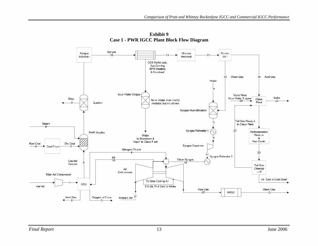
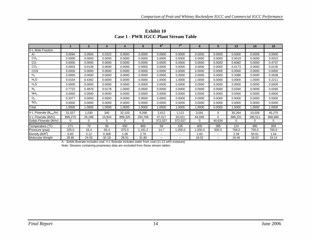
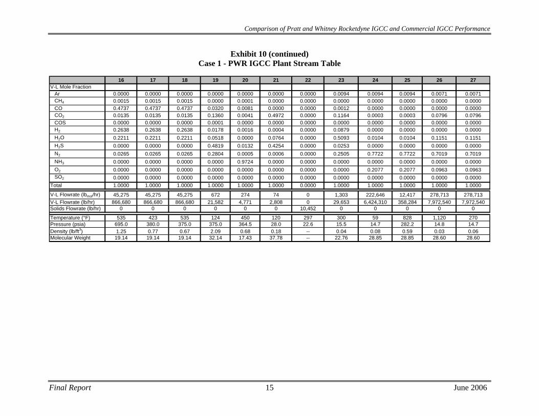
A block flow diagram and associated stream tables for the Case 1 PWR gasifier-based IGCC plant in radiant quench heat recovery mode are presented in Exhibit 9 and Exhibit 10, respectively. Performance, capital costs and operating costs are presented in Exhibit 11 through Exhibit 14.
2.1 Process Description The Case 1 PWR IGCC plant consists of two compact, radiant-cooled gasifiers each fed with approximately 1,800 tpd of 95% oxygen produced from an on site Air Separation Unit (ASU) and approximately 2,500 tpd of Illinois #6 coal dried from 11.12% to 5% in a syngas/HRSG gas-fired coal dryer. It is assumed that Illinois #6 coal has 5% inherent moisture.
A proprietary PWR coal extrusion feed system is utilized for feeding dried coal to the PWR gasifier. Each gasifier train in the PWR process requires approximately 130 tpd of nitrogen from the Air Separation Unit as coal transport gas as well as approximately 390 tpd of steam injection.
The PWR process claims an adiabatic flame temperature of ~2600°F, 1,000 psig operating pressure, and 100% carbon conversion. Approximately 490 tpd of slag (100% ash) is removed from the gasification reaction products as hot syngas and molten solids from the reactor flow downward into a radiant cooler where the syngas is cooled and the ash solidifies. Raw syngas continues downward into a quench system and then into a syngas scrubber for removal of entrained solids. Since the syngas temperature exiting the quench is too low for COS hydrolysis to efficiently occur, the syngas is heated to 400°F before entering a hydrolysis reactor, where >99% of the carbonyl sulfide is converted to hydrogen sulfide. The gas is then cooled to ~100°F and cleaned of ammonia and mercury prior to feeding the gas to the acid gas removal system.
A single stage Selexol AGR process separates the syngas into an acid gas stream containing hydrogen sulfide and carbon dioxide, and into a sweet gas stream containing the fuel gas to be combusted in the gas turbine. The acid gas stream is sent to a two bed Claus sulfur recovery plant with a tail gas clean up unit. Using approximately 130 tpd of 95% oxygen, the Claus process catalytically converts the gaseous sulfur compounds into elemental sulfur for collection and sale. A hydrogenation reactor converts the remaining gaseous sulfur dioxide into hydrogen sulfide, which may be separated from the tail gas in an MDEA tail gas treating unit. H2S is then recycled back to the Claus plant thermal reaction zone to improve overall sulfur recovery.
The clean synthesis gas stream exits the Selexol unit at approximately 125°F, where it is humidified with hot water at 380°F. The humidifier accomplishes some reheating of the syngas while partially diluting the gas for NOx mitigation in the gas turbine combustors. After sulfur removal, the sweet fuel gas is also depressurized through an expander from 695 psia to 380 psia to generate ~12 MWe of power.
Further reheating of the syngas, to 535°F, improves the gas turbine heat rate by reducing the amount of combustion energy used for heating the gas. In order to minimize NOx formation, the synthesis gas must be diluted to ~120 Btu/scf (LHV basis). Approximately 11,000 tpd of
Final Report 9 June 2006
Comparison of Pratt and Whitney Rocketdyne IGCC and Commercial IGCC Performance
nitrogen diluent and 1,700 tpd of steam are added to accomplish the dilution. The resultant fuel gas stream is combined with compressed and heated ambient air and then combusted in two parallel General Electric 7FB model turbines.
The combustion products exiting the gas turbines are fed to a HRSG for heat recovery and additional power production before discharge to the atmosphere.
2.2 Modeling Assumptions for PWR Gasifier
PWR has made the following assumptions about their gasifier performance in the absence of substantial pilot data. These assumptions were used in the RDS analysis:
1. 100% carbon conversion based on expectations of the multi-injection port nozzle and high coal particle heat rate.
2. Fuel-bound atomic species exist in their elemental state for the purposes of the Gibbs Free Energy minimization calculations.
3. Unrestricted Gibbs Free Energy Minimization calculations for most governing gasification reactions due to the prototype reactor design features, which support assumptions of ideality: high coal particle heat rate, uniform coal distribution and 100% carbon conversion.
4. 80% of fuel-bound nitrogen is converted to ammonia. Gibbs Free Energy Minimization calculations for the ammonia-forming gasification reaction was manipulated to achieve this vendor-specified value.
RDS assessment of the five main modeling assumptions used in the study is:
1. The multi-port injection nozzle theoretically will promote improved mixing and gasification, which may result in an improved coal particle heat rate and an even temperature distribution. However, this assumption is optimistic and will have to be proven in actual demonstrations. The performance estimates made on this assumption must be considered a “best case scenario”.
2. This is a common assumption made in systems analyses that produces reasonable results.
3. Unrestricted Gibbs Free Energy Minimization generally does not produce results that match actual performance for current commercial systems. Non-idealities that occur in either pilot scale or commercial scale reactors are not accounted for in this method. The efficiency of the gasifier, as a result, must be considered an upper-limit “best case scenario”. Sensitivity studies will be required to determine the impact of incorporating these non-idealities on a case to case basis.
4. RDS has found few instances where near 80% of fuel-bound nitrogen is converted to ammonia. According to results published in the EPRI Coal Gasification Guidebook [9], 10-20% seems to be a reasonable assumption. With all other things equal, the increase in available hydrogen in the case converting 10% of fuel-bound N2 over the case converting 80% of fuel-bound N2, can result in an absolute increase in gasifier overall cold gas efficiency (including ammonia and sulfur species) of up to 0.35%.
Final Report 10 June 2006
Comparison of Pratt and Whitney Rocketdyne IGCC and Commercial IGCC Performance
Background Information Provided by PWR
PWR provided the following text to describe the history and source of their gasifier performance projections:
PWR advanced gasifier performance predictions are based on a proprietary one-dimensional kinetic model validated with experimental data from earlier PWR work with coal-fired systems in the areas of hydrogasification-liquefaction, steam/oxygen gasification, magnetohydrodynamic (MHD) power, acetylene production, and low NOx/SOx combustion. [1, 2]
The kinetic model describes entrained flow gasifier reactor dynamics in terms of the following physical and chemical phenomena:
(1) Particle boundary layer transport
(2) Conservation equations of the bulk flow
(3) Chemical reactions of the freestream
(4) Thermochemical and freestream transport properties
(5) Convective and radiative heat transfer between the gasifier walls and internal process stream.
(6) Detailed coal devolatilization kinetics, heterogeneous oxidation/gasification kinetics, and mass transport within the pore structure of the particles. This PWR proprietary coal particle sub-model is fundamentally as detailed as the recent published work by Niksa et al. [4].
Reactant mixing was demonstrated to occur at the point where the impinging coal and steam/oxygen streams meet in previous work at PWR [3]. This allows modeling of the entrained flow gasifier on the basis of uniformly mixed reactants across the reactor cross section.
The kinetic model uses freestream gas equilibrium in those regions where the gas temperatures are high (usually above 2,000°F) and the kinetics are extremely fast. Otherwise homogeneous gas phase kinetics is incorporated. All kinetic and equilibrium calculations are based on localized conditions within the freestream gas or coal particle.
In addition to the one-dimensional kinetic model, PWR also uses a chemical equilibrium computer code -- based upon the NASA code, “Chemical Equilibrium for Analysis” – as an initial first cut approximation for slagging entrained flow coal gasifiers. These chemical equilibrium results are modified to reflect past experience that NH3 content is considerably higher than equilibrium predictions. Based on hydrogasification experimental and one-dimensional kinetic model results, it is assumed that 80% of the fuel-bound nitrogen is converted to ammonia and does not equilibrate with the free-stream gas. The PWR equilibrium model is also capable of including heat loss estimates through the gasifier walls.
For the first cut slagging gasifier equilibrium approximation, the gasifier product gas is based on the freestream chemical equilibrium calculated at the exit point. Unconverted carbon (due to kinetic constraints) is treated as an inert for the purpose of equilibrium calculations, as it is throughout the reactor. The amount of unconverted carbon and reactor
Final Report 11 June 2006
Comparison of Pratt and Whitney Rocketdyne IGCC and Commercial IGCC Performance
Final Report 12 June 2006
heat losses can be provided from either actual experimental results or the one-dimensional kinetic model described above.
Carbon conversion predictions from the one-dimensional kinetic model have been anchored to a limited amount of experimental kinetics data. The pilot plant gasifier will provide a means to vary process parameters (reactant flow rates and conditions, reactor length, residence times, and pressures) and monitor results (carbon conversion, syngas composition, heat losses) to continue validating model kinetics. Though the carbon conversion in actual operation will be limited by design and operating constraints, it was assumed in this study that 100% carbon conversion is achieved.
Comparison of Pratt and Whitney Rocketdyne IGCC and Commercial IGCC Performance
Exhibit 9 Case 1 - PWR IGCC Plant Block Flow Diagram
Final Report 13 June 2006
Comparison of Pratt and Whitney Rocketdyne IGCC and Commercial IGCC Performance
Exhibit 10 Case 1 - PWR IGCC Plant Stream Table
1 2 3 4 5 6A 7A 8 9 13 14 15V-L Mole Fraction
Ar 0.0094 0.0594 0.0322 0.0000 0.0000 0.0000 0.0000 0.0000 0.0000 0.0000 0.0000 0.0000CH4 0.0000 0.0000 0.0000 0.0000 0.0000 0.0000 0.0000 0.0000 0.0000 0.0019 0.0000 0.0015CO 0.0000 0.0000 0.0000 0.0000 0.0000 0.0000 0.0000 0.0000 0.0000 0.6082 0.0000 0.4737CO2 0.0003 0.0138 0.0000 0.0000 0.0000 0.0000 0.0000 0.0000 0.0000 0.0173 0.0000 0.0135COS 0.0000 0.0000 0.0000 0.0000 0.0000 0.0000 0.0000 0.0000 0.0000 0.0000 0.0000 0.0000H2 0.0000 0.0000 0.0000 0.0000 0.0000 0.0000 0.0000 0.0000 0.0000 0.3386 0.0000 0.2638H2O 0.0104 0.4392 0.0000 0.0000 0.0000 1.0000 1.0000 1.0000 0.0000 0.0000 1.0000 0.2211H2S 0.0000 0.0000 0.0000 0.0000 0.0000 0.0000 0.0000 0.0000 0.0000 0.0000 0.0000 0.0000N2 0.7722 0.4876 0.0178 1.0000 0.0500 0.0000 0.0000 0.0000 0.0000 0.0340 0.0000 0.0265NH3 0.0000 0.0000 0.0000 0.0000 0.0000 0.0000 0.0000 0.0000 0.0000 0.0000 0.0000 0.0000O2 0.2077 0.0000 0.9500 0.0000 0.9500 0.0000 0.0000 0.0000 0.0000 0.0000 0.0000 0.0000SO2 0.0000 0.0000 0.0000 0.0000 0.0000 0.0000 0.0000 0.0000 0.0000 0.0000 0.0000 0.0000
Total 1.0000 1.0000 1.0000 1.0000 1.0000 1.0000 1.0000 1.0000 0.0000 1.0000 1.0000 1.0000
V-L Flowrate (lbmol/hr) 31,027 1,030 340 32,103 9,268 2,612 1,112 3,591 0 35,264 10,028 45,275V-L Flowrate (lb/hr) 895,275 25,288 10,944 899,325 294,706 47,017 20,021 64,695 0 686,321 180,511 866,680Solids Flowrate (lb/hr) 0 0 0 0 0 372,027 372,027 0 40,634 0 0 0
Temperature (°F) 271 70 90 450 800 59 195 800 385 124 380 359Pressure (psia) 225.0 16.4 56.4 375.0 1,191.2 14.7 1,200.0 1,200.0 930.0 768.0 755.0 700.0Density (lb/ft3) 0.83 0.12 0.308 1.08 2.76 -- -- 1.60 -- 2.39 50.61 1.54Molecular Weight 28.85 24.55 32.18 28.01 31.80 -- -- 18.02 -- 19.46 18.02 19.14
A - Solids flowrate includes coal; V-L flowrate includes water from coal (11.12 wt% moisture)Note: Streams containing proprietary data are excluded from these stream tables.
Final Report 14 June 2006
Final Report 15 June 2006
16 17 18 19 20 21 22 23 24 25 26 27V-L Mole Fraction
Ar 0.0000 0.0000 0.0000 0.0000 0.0000 0.0000 0.0000 0.0094 0.0094 0.0094 0.0071 0.0071CH4 0.0015 0.0015 0.0015 0.0000 0.0001 0.0000 0.0000 0.0000 0.0000 0.0000 0.0000 0.0000CO 0.4737 0.4737 0.4737 0.0320 0.0081 0.0000 0.0000 0.0012 0.0000 0.0000 0.0000 0.0000CO2 0.0135 0.0135 0.0135 0.1360 0.0041 0.4972 0.0000 0.1164 0.0003 0.0003 0.0796 0.0796COS 0.0000 0.0000 0.0000 0.0001 0.0000 0.0000 0.0000 0.0000 0.0000 0.0000 0.0000 0.0000H2 0.2638 0.2638 0.2638 0.0178 0.0016 0.0004 0.0000 0.0879 0.0000 0.0000 0.0000 0.0000H2O 0.2211 0.2211 0.2211 0.0518 0.0000 0.0764 0.0000 0.5093 0.0104 0.0104 0.1151 0.1151H2S 0.0000 0.0000 0.0000 0.4819 0.0132 0.4254 0.0000 0.0253 0.0000 0.0000 0.0000 0.0000N2 0.0265 0.0265 0.0265 0.2804 0.0005 0.0006 0.0000 0.2505 0.7722 0.7722 0.7019 0.7019NH3 0.0000 0.0000 0.0000 0.0000 0.9724 0.0000 0.0000 0.0000 0.0000 0.0000 0.0000 0.0000O2 0.0000 0.0000 0.0000 0.0000 0.0000 0.0000 0.0000 0.0000 0.2077 0.2077 0.0963 0.0963SO2 0.0000 0.0000 0.0000 0.0000 0.0000 0.0000 0.0000 0.0000 0.0000 0.0000 0.0000 0.0000
Total 1.0000 1.0000 1.0000 1.0000 1.0000 1.0000 0.0000 1.0000 1.0000 1.0000 1.0000 1.0000
V-L Flowrate (lbmol/hr) 45,275 45,275 45,275 672 274 74 0 1,303 222,646 12,417 278,713 278,713V-L Flowrate (lb/hr) 866,680 866,680 866,680 21,582 4,771 2,808 0 29,653 6,424,310 358,284 7,972,540 7,972,540Solids Flowrate (lb/hr) 0 0 0 0 0 0 10,452 0 0 0 0 0
Temperature (°F) 535 423 535 124 450 120 297 300 59 828 1,120 270Pressure (psia) 695.0 380.0 375.0 375.0 364.5 28.0 22.6 15.5 14.7 282.2 14.8 14.7Density (lb/ft3) 1.25 0.77 0.67 2.09 0.68 0.18 -- 0.04 0.08 0.59 0.03 0.06Molecular Weight 19.14 19.14 19.14 32.14 17.43 37.78 -- 22.76 28.85 28.85 28.60 28.60
Comparison of Pratt and Whitney Rocketdyne IGCC and Commercial IGCC Performance
Exhibit 10 (continued) Case 1 - PWR IGCC Plant Stream Table
Comparison of Pratt and Whitney Rocketdyne IGCC and Commercial IGCC Performance
2.3 Equipment Descriptions
Coal Preparation and Feed Systems The coal as received contains 11.12 percent moisture, part of which is surface moisture (that which is easily removed from the coal) with the balance being inherent (chemically bound) moisture. For transportation of the coal at high pressure, drying of the surface moisture is required. For the purposes of this study, it was assumed that there is 5 percent inherent moisture in the coal and that the coal is dried to this level as a result. The coal is simultaneously crushed and dried using a combination of Claus tail gas and air. Crushed and dried coal is delivered to a surge hopper with an approximate 2-hour capacity.
The coal is drawn from the surge hoppers and fed through a developmental proprietary dry coal feed pump system, which uses nitrogen to convey the coal to the gasifiers.
Air Separation Unit The air separation plant is designed to produce a nominal output of 3,700 tons/day of 95 percent pure O2 from two ASU production trains. Most of the oxygen is used in the gasifier. A small portion, approximately 130 tons/day, is used in the Claus plant. The air compressor is powered by an electric motor. Approximately 11,000 tons/day of nitrogen are also recovered, compressed, and used for syngas dilution for NOx mitigation in the gas turbine combustor and as a carrying gas for coal transport into the gasifier.
Gasifier The PWR gasifier is a plug-flow entrained reactor with a multi-port injection nozzle to increase the kinetics and conversion of the gasification reaction. The PWR gasification process gasifies dried coal with steam and 95% (by volume) oxygen at ~2600°F and 1,000 psia. The PWR process claims a 100% carbon conversion and faster kinetics allowing for a more compact gasifier design. The prototype reactor designed to process 3,000 tons of dried coal per day is anticipated to be 39 inches in diameter and 15 feet in length. The amount of dried coal processed is approximately 5,000 tons per day.
Syngas Cooling Hot syngas and molten solids from the reactor flow downward through a radiant heat exchanger where the syngas is cooled to 1,000°F. High pressure steam is generated in the radiant cooler and is superheated in the HRSG by the gas turbine exhaust. The gas and solidified slag then flow into a water-filled quench chamber. Raw syngas saturated at about 380°F then flows to the syngas scrubber for removal of entrained solids. The solids collect in the water sump at the bottom of the gasifier and are removed periodically, using a lock hopper system.
Solids collected in the quench gasifier water sump are removed by gravity and forced circulation of water from the lock hopper circulating pump. Fine material, which does not settle as easily, is removed in the gasification blowdown which is sent to the vacuum flash drum by way of the syngas scrubber.
Final Report 16 June 2006
Comparison of Pratt and Whitney Rocketdyne IGCC and Commercial IGCC Performance
Syngas Scrubbing
The syngas enters the syngas scrubber and is directed downwards by a dip tube into a water sump at the bottom of the syngas scrubber. Most of the solids are separated from the syngas at the bottom of the dip tube as the syngas goes upwards through the water. From the overhead of the syngas scrubber, the syngas enters the low-temperature gas cooling section for further cooling.
The water removed from the syngas scrubber contains all the solids that were not removed in the quench gasifier water sump. In order to limit the amount of solids recycled to the quench chamber, a continuous blowdown stream is removed from the bottom of the syngas scrubber. The blowdown is sent to the vacuum flash drum in the black water flash section. The circulating scrubbing water is pumped by the syngas scrubber circulating pumps to the quench gasifier.
The slag handling system removes solids from the gasification process equipment. These solids will consist of any unconverted carbon and essentially all of the ash contained in the feed coal. Since we have assumed 100% carbon conversion in this study, the “slag” will be 100% ash. These solids are in the form of glass, which is non-leaching and fully encapsulates any metals.
COS Hydrolysis / Low Temperature Gas Cooling H2S and COS are at significant concentrations, requiring removal for the power plant to achieve the low design level of SO2 emissions. H2S is removed in an acid gas removal process; however, because COS is not readily removable, it is first catalytically converted to H2S in a COS hydrolysis unit.
Following the quench/scrubber system, the gas is reheated to ~400°F and fed to the COS hydrolysis reactor. The COS is hydrolyzed with steam in the gas over a catalyst bed to H2S, which is more easily removed by the AGR solvent. Any HCN in the syngas will also be reacted in the COS hydrolysis unit.
Before the raw fuel gas can be treated in the AGR process, it must be cooled to about 100°F. During this cooling through a series of heat exchangers, part of the water vapor condenses. This water, which contains some NH3, is sent to the wastewater treatment section.
Mercury Removal Mercury removal was based on packed beds of sulfur-impregnated carbon similar to what has been used at Eastman Chemical’s gasification plant. Dual beds of sulfur-impregnated carbon with approximately a 20-second superficial gas residence time should achieve >90 percent reduction of mercury in addition to removal of other volatile heavy metals such as arsenic.
Acid Gas Removal Case 1 utilizes a single-train Selexol process to remove sulfur with minimal CO2 capture. The Selexol process treats the stream of synthesis gas to reduce the level of total sulfur (H2S and COS) to no more than 30 ppm prior to it being sent to the combustion turbine, while maximizing the CO2 slip. A recycle stream of acid gas from the sulfur recovery unit (SRU) is also treated. An acid gas stream that contains ~50 percent sulfur is produced.
Untreated gas is sent to the absorber, where it contacts cooled regenerated solvent, which enters at the top of the tower. In the absorber, H2S, COS, CO2, and other gases such as hydrogen, are
Final Report 17 June 2006
Comparison of Pratt and Whitney Rocketdyne IGCC and Commercial IGCC Performance
transferred from the gas phase to the liquid phase. The treated gas exits the absorber and is sent to fuel gas saturation and the expander.
The solvent streams from the absorber and reabsorber are termed rich solvent, and are combined and sent to the lean/rich exchanger. In the lean/rich exchanger, the temperature of the rich solvent is increased by heat exchange with the lean solvent. The rich solvent is then sent to the H2S concentrator, where portions of the CO2, CO, H2, and other gases are stripped from the solvent. Nitrogen from the ASU is used as the stripping medium. The temperature of the overhead stream from the H2S concentrator is reduced in the stripped gas cooler. The stream is then sent to the reabsorber, where H2S, COS, and a portion of the other gases are transferred to the liquid phase. The stream from the reabsorber is sent to the gas turbine.
The partially regenerated solvent exits the H2S concentrator and is sent to the stripper, where the solvent is regenerated. Tail gas from the SRU is recycled back to the AGR unit and enters with the feed to the reabsorber.
Sour Water Stripper The sour water stripper removes NH3, H2S, and other impurities from the waste stream of the scrubber and water condensed in the low temperature gas cooling section. The sour gas stripper consists of a sour drum that accumulates sour water from the gas scrubber and condensate from syngas coolers. Sour water from the drum flows to the sour stripper, which consists of a packed column with a steam-heated reboiler. Sour gas is stripped from the liquid and sent to the sulfur recovery unit. Remaining water is sent to wastewater treatment.
Sulfur Recovery System The sulfur recovery unit is a Claus bypass type sulfur recovery unit utilizing oxygen instead of air followed by a SCOT tail gas unit. The Claus plant produces molten sulfur by reacting approximately one third of the H2S in the feed to SO2, then reacting the H2S and SO2 to sulfur and water. The combination of Claus technology and SCOT tail gas technology will result in a sulfur recovery exceeding 99 percent of that fed to the Claus plant and a vent gas of less than 2 ppmv of SO2.
Utilizing oxygen instead of air in the Claus plant reduces the overall cost of the sulfur recovery plant. The sulfur plant will produce approximately 112 long tons of elemental sulfur per day. Feed for this case consists of acid gas from both acid gas cleanup units and a vent stream from the sour water stripper in the gasifier section. Vent gas from the tail gas treatment unit is vented to the coal dryer, contributing to total plant sulfur emissions of less than 0.022 lb/MMBtu, meeting air quality standards.
Syngas Expander After sulfur removal, the sweet fuel gas is saturated with condensate, reheated, and depressurized through an expander from 695 psia to 380 psia, which is near the pressure required by the gas turbine. The expander generates ~12 MWe of power.
Gas Turbine Generator Both of the combustion turbine generators are General Electric 7FB model turbines modified for syngas firing. The maximum output of each is expected to be 232 MW, based on the rotor
Final Report 18 June 2006
Comparison of Pratt and Whitney Rocketdyne IGCC and Commercial IGCC Performance
torque limit. Each machine is an axial flow, single spool, constant speed unit, equipped with variable inlet guide vanes and syngas version of diffusion-flame combustor with nitrogen diluent injection. The turbine exhaust gases are conveyed through a HRSG to recover the large quantities of thermal energy that remain.
The gas turbine generator selected for this application is based on a natural gas fired 7FB machine. In this service, with syngas from an IGCC plant, the machine requires some modifications to the burner and turbine nozzles in order to properly combust the medium-Btu gas and expand the combustion products in the turbine section of the machine. A reduction in rotor inlet temperature of about 50°F is expected, relative to a production model 7FB machine firing natural gas. This temperature reduction may be necessary to not exceed design basis gas path temperatures throughout the expander. If the first-stage rotor inlet temperature were maintained at the design value, gas path temperatures downstream of the inlet to the first (HP) turbine stage may increase, relative to natural-gas-fired temperatures, due to gas property changes.
The syngas fired 7FB gas turbine is a developmental machine that GE expects to have available in the 2010 time frame for commercial applications.
Heat Recovery Steam Generator / Steam Turbine The HRSG supplies steam to a steam turbine generator which is a tandem compound, two-flow exhaust, single reheat, condensing, GE model D-11, or equal. The steam turbine consists of an HP section, an IP section, and one double-flow LP section, all connected to the generator by a common shaft. The HP and IP sections are contained in a single-span, opposed-flow casing, with the double-flow LP section in a separate casing. The overall power output from the steam turbine is 230.7 MWe.
2.4 Performance Results For the Case 1 PWR IGCC plant, the combustion turbines are two General Electric 7FB model turbines in parallel, each producing 232 MWe for a total of 464 MWe. The steam turbine produces 230.7 MWe (gross), and the sweet gas expander produces 11.8 MWe. Total auxiliary power required is 101.3 MWe, yielding a net plant power output of 605.2 MWe.
Overall plant efficiency (HHV) is 42.2% equating to a heat rate of 8,078 Btu/kWh (HHV).
The performance results are summarized in Exhibit 11.
Final Report 19 June 2006
Comparison of Pratt and Whitney Rocketdyne IGCC and Commercial IGCC Performance
Final Report 20 June 2006
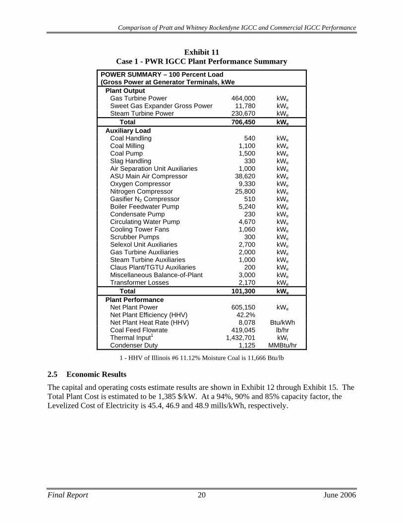
Exhibit 11 Case 1 - PWR IGCC Plant Performance Summary
POWER SUMMARY – 100 Percent Load (Gross Power at Generator Terminals, kWe
Plant Output Gas Turbine Power 464,000 kWeSweet Gas Expander Gross Power 11,780 kWeSteam Turbine Power 230,670 kWe
Total 706,450 kWe
Auxiliary Load Coal Handling 540 kWeCoal Milling 1,100 kWeCoal Pump 1,500 kWeSlag Handling 330 kWeAir Separation Unit Auxiliaries 1,000 kWeASU Main Air Compressor 38,620 kWeOxygen Compressor 9,330 kWeNitrogen Compressor 25,800 kWeGasifier N2 Compressor 510 kWeBoiler Feedwater Pump 5,240 kWeCondensate Pump 230 kWeCirculating Water Pump 4,670 kWeCooling Tower Fans 1,060 kWeScrubber Pumps 300 kWeSelexol Unit Auxiliaries 2,700 kWeGas Turbine Auxiliaries 2,000 kWeSteam Turbine Auxiliaries 1,000 kWeClaus Plant/TGTU Auxiliaries 200 kWeMiscellaneous Balance-of-Plant 3,000 kWeTransformer Losses 2,170 kWe
Total 101,300 kWe
Plant Performance Net Plant Power 605,150 kWeNet Plant Efficiency (HHV) 42.2% Net Plant Heat Rate (HHV) 8,078 Btu/kWh Coal Feed Flowrate 419,045 lb/hr Thermal Input1 1,432,701 kWtCondenser Duty 1,125 MMBtu/hr
1 - HHV of Illinois #6 11.12% Moisture Coal is 11,666 Btu/lb
2.5 Economic Results
The capital and operating costs estimate results are shown in Exhibit 12 through Exhibit 15. The Total Plant Cost is estimated to be 1,385 $/kW. At a 94%, 90% and 85% capacity factor, the Levelized Cost of Electricity is 45.4, 46.9 and 48.9 mills/kWh, respectively.
Final Report 21 June 2006
Comparison of Pratt and Whitney Rocketdyne IGCC and Commercial IGCC Performance
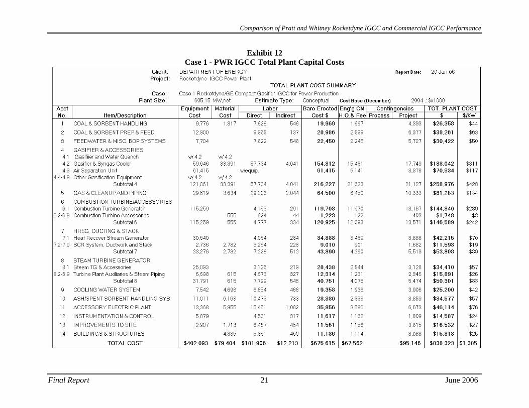
Exhibit 12 Case 1 - PWR IGCC Total Plant Capital Costs
Comparison of Pratt and Whitney Rocketdyne IGCC and Commercial IGCC Performance
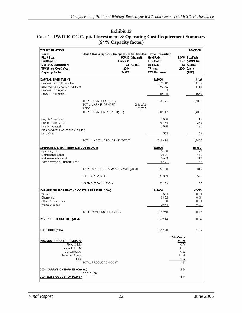
Exhibit 13 Case 1 - PWR IGCC Capital Investment & Operating Cost Requirement Summary
(94% Capacity factor)
Final Report 22 June 2006
Comparison of Pratt and Whitney Rocketdyne IGCC and Commercial IGCC Performance
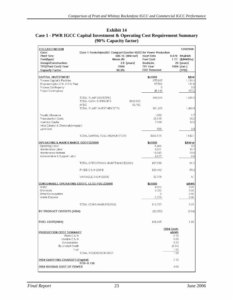
Exhibit 14 Case 1 - PWR IGCC Capital Investment & Operating Cost Requirement Summary
(90% Capacity factor)
Final Report 23 June 2006
Comparison of Pratt and Whitney Rocketdyne IGCC and Commercial IGCC Performance
Exhibit 15 Case 1 - PWR IGCC Capital Investment & Operating Cost Requirement Summary
(85% Capacity factor)
Final Report 24 June 2006
Comparison of Pratt and Whitney Rocketdyne IGCC and Commercial IGCC Performance
Final Report 25 June 2006
3 CASE 2 - GE ENERGY GASIFIER BASED IGCC PLANT DESCRIPTION AND RESULTS
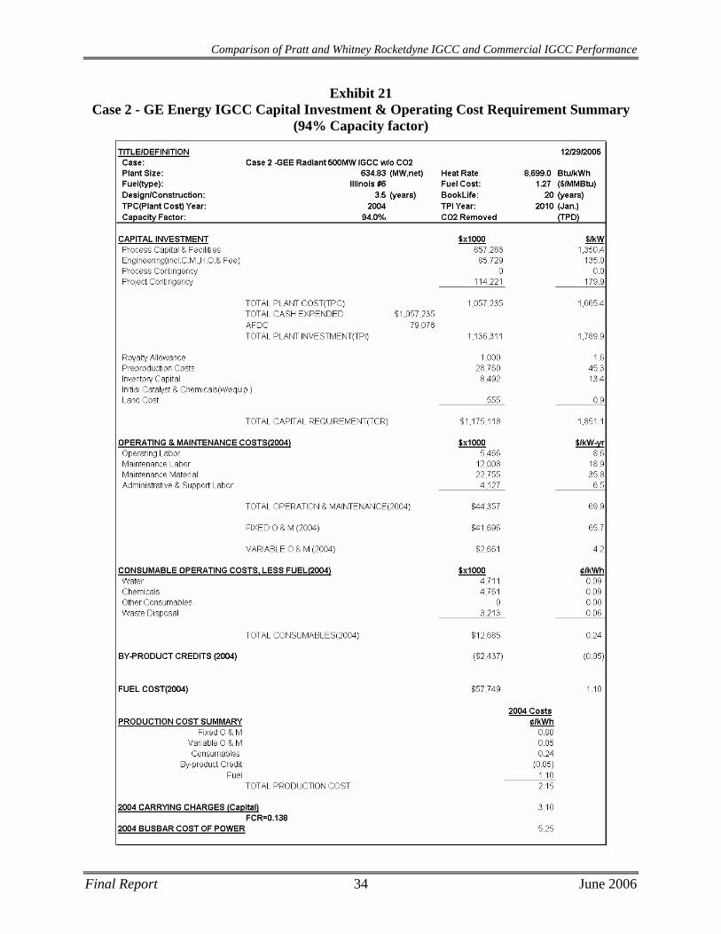
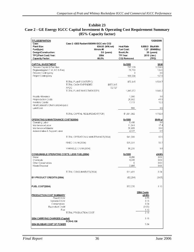
Case 2 produces 634.8 MWe at 39.2% efficiency (8,669 BTU/kWh heat rate). The TPC is $972MM and, at 85% CF, produces electricity at 53.4 mills/kWh. Adding a spare gasification train increases the TPC to $1,057MM and, at 90% CF, results in a LCOE of 54.3 mills/kWh, and at 94% CF, results in a LCOE of 52.5 mills/kWh
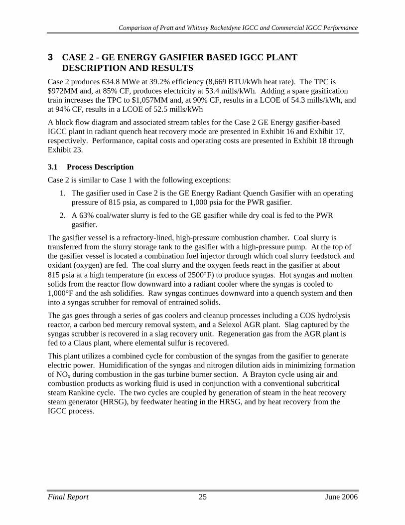
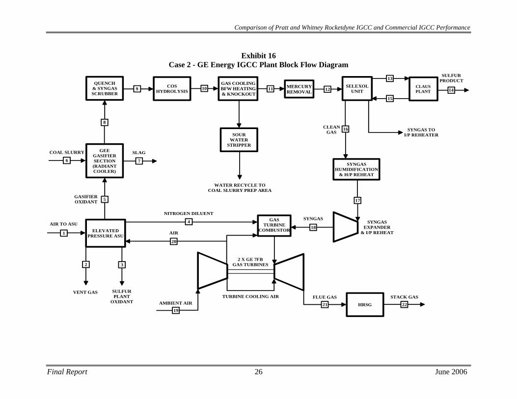
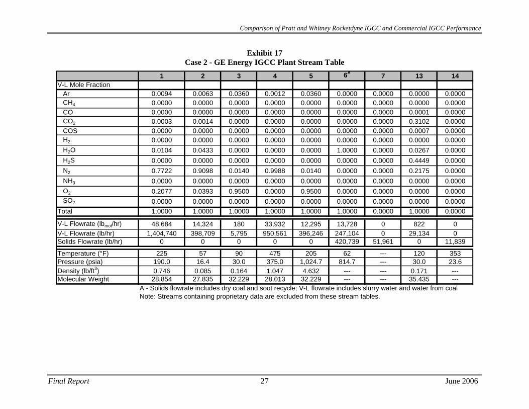
A block flow diagram and associated stream tables for the Case 2 GE Energy gasifier-based IGCC plant in radiant quench heat recovery mode are presented in Exhibit 16 and Exhibit 17, respectively. Performance, capital costs and operating costs are presented in Exhibit 18 through Exhibit 23.
3.1 Process Description Case 2 is similar to Case 1 with the following exceptions:
1. The gasifier used in Case 2 is the GE Energy Radiant Quench Gasifier with an operating pressure of 815 psia, as compared to 1,000 psia for the PWR gasifier.
2. A 63% coal/water slurry is fed to the GE gasifier while dry coal is fed to the PWR gasifier.
The gasifier vessel is a refractory-lined, high-pressure combustion chamber. Coal slurry is transferred from the slurry storage tank to the gasifier with a high-pressure pump. At the top of the gasifier vessel is located a combination fuel injector through which coal slurry feedstock and oxidant (oxygen) are fed. The coal slurry and the oxygen feeds react in the gasifier at about 815 psia at a high temperature (in excess of 2500°F) to produce syngas. Hot syngas and molten solids from the reactor flow downward into a radiant cooler where the syngas is cooled to 1,000°F and the ash solidifies. Raw syngas continues downward into a quench system and then into a syngas scrubber for removal of entrained solids.
The gas goes through a series of gas coolers and cleanup processes including a COS hydrolysis reactor, a carbon bed mercury removal system, and a Selexol AGR plant. Slag captured by the syngas scrubber is recovered in a slag recovery unit. Regeneration gas from the AGR plant is fed to a Claus plant, where elemental sulfur is recovered.
This plant utilizes a combined cycle for combustion of the syngas from the gasifier to generate electric power. Humidification of the syngas and nitrogen dilution aids in minimizing formation of NOx during combustion in the gas turbine burner section. A Brayton cycle using air and combustion products as working fluid is used in conjunction with a conventional subcritical steam Rankine cycle. The two cycles are coupled by generation of steam in the heat recovery steam generator (HRSG), by feedwater heating in the HRSG, and by heat recovery from the IGCC process.
Comparison of Pratt and Whitney Rocketdyne IGCC and Commercial IGCC Performance
Exhibit 16 Case 2 - GE Energy IGCC Plant Block Flow Diagram
GEEGASIFIERSECTION(RADIANT COOLER)
SOURWATER
STRIPPER
ELEVATEDPRESSURE ASU
QUENCH& SYNGASSCRUBBER
GAS COOLINGBFW HEATING & KNOCKOUT
COSHYDROLYSIS
COAL SLURRY
6
5GASIFIEROXIDANT
7
SLAG
AIR TO ASU
VENT GAS
1
2
8
9
13
18
10
HRSG
2 X GE 7FBGAS TURBINES
1921 22AMBIENT AIR
TURBINE COOLING AIR FLUE GAS STACK GAS
SELEXOLUNIT
SULFURPLANT
OXIDANT
3
11
SYNGASNITROGEN DILUENT
4
WATER RECYCLE TOCOAL SLURRY PREP AREA
CLAUSPLANT 14
SULFURPRODUCT
CLEANGAS
20
AIR
MERCURYREMOVAL 12
17
SYNGASEXPANDER
& I/P REHEAT
SYNGASHUMIDIFICATION
& H/P REHEAT
GASTURBINE
COMBUSTOR
16
15
SYNGAS TOI/P REHEATER
Final Report 26 June 2006
Comparison of Pratt and Whitney Rocketdyne IGCC and Commercial IGCC Performance
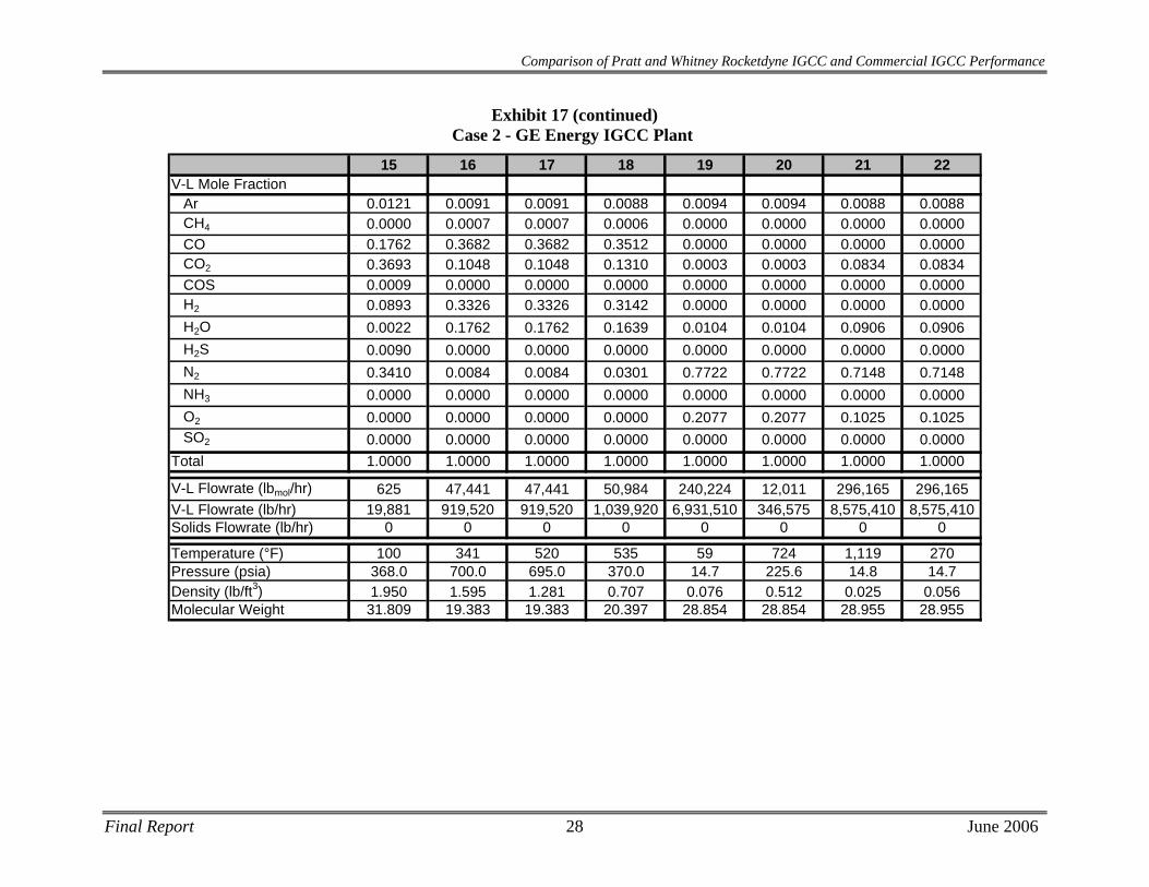
Exhibit 17 Case 2 - GE Energy IGCC Plant Stream Table
1 2 3 4 5 6A 7 13 14V-L Mole Fraction
Ar 0.0094 0.0063 0.0360 0.0012 0.0360 0.0000 0.0000 0.0000 0.0000CH4 0.0000 0.0000 0.0000 0.0000 0.0000 0.0000 0.0000 0.0000 0.0000CO 0.0000 0.0000 0.0000 0.0000 0.0000 0.0000 0.0000 0.0001 0.0000CO2 0.0003 0.0014 0.0000 0.0000 0.0000 0.0000 0.0000 0.3102 0.0000COS 0.0000 0.0000 0.0000 0.0000 0.0000 0.0000 0.0000 0.0007 0.0000H2 0.0000 0.0000 0.0000 0.0000 0.0000 0.0000 0.0000 0.0000 0.0000H2O 0.0104 0.0433 0.0000 0.0000 0.0000 1.0000 0.0000 0.0267 0.0000H2S 0.0000 0.0000 0.0000 0.0000 0.0000 0.0000 0.0000 0.4449 0.0000N2 0.7722 0.9098 0.0140 0.9988 0.0140 0.0000 0.0000 0.2175 0.0000NH3 0.0000 0.0000 0.0000 0.0000 0.0000 0.0000 0.0000 0.0000 0.0000O2 0.2077 0.0393 0.9500 0.0000 0.9500 0.0000 0.0000 0.0000 0.0000SO2 0.0000 0.0000 0.0000 0.0000 0.0000 0.0000 0.0000 0.0000 0.0000
Total 1.0000 1.0000 1.0000 1.0000 1.0000 1.0000 0.0000 1.0000 0.0000
V-L Flowrate (lbmol/hr) 48,684 14,324 180 33,932 12,295 13,728 0 822 0V-L Flowrate (lb/hr) 1,404,740 398,709 5,795 950,561 396,246 247,104 0 29,134 0Solids Flowrate (lb/hr) 0 0 0 0 0 420,739 51,961 0 11,839
Temperature (°F) 225 57 90 475 205 62 --- 120 353Pressure (psia) 190.0 16.4 30.0 375.0 1,024.7 814.7 --- 30.0 23.6Density (lb/ft3) 0.746 0.085 0.164 1.047 4.632 --- --- 0.171 ---Molecular Weight 28.854 27.835 32.229 28.013 32.229 --- --- 35.435 ---
A - Solids flowrate includes dry coal and soot recycle; V-L flowrate includes slurry water and water from coalNote: Streams containing proprietary data are excluded from these stream tables.
Final Report 27 June 2006
Final Report 28 June 2006
Comparison of Pratt and Whitney Rocketdyne IGCC and Commercial IGCC Performance
15 16 17 18 19 20 21 22V-L Mole Fraction
Ar 0.0121 0.0091 0.0091 0.0088 0.0094 0.0094 0.0088 0.0088CH4 0.0000 0.0007 0.0007 0.0006 0.0000 0.0000 0.0000 0.0000CO 0.1762 0.3682 0.3682 0.3512 0.0000 0.0000 0.0000 0.0000CO2 0.3693 0.1048 0.1048 0.1310 0.0003 0.0003 0.0834 0.0834COS 0.0009 0.0000 0.0000 0.0000 0.0000 0.0000 0.0000 0.0000H2 0.0893 0.3326 0.3326 0.3142 0.0000 0.0000 0.0000 0.0000H2O 0.0022 0.1762 0.1762 0.1639 0.0104 0.0104 0.0906 0.0906H2S 0.0090 0.0000 0.0000 0.0000 0.0000 0.0000 0.0000 0.0000N2 0.3410 0.0084 0.0084 0.0301 0.7722 0.7722 0.7148 0.7148NH3 0.0000 0.0000 0.0000 0.0000 0.0000 0.0000 0.0000 0.0000O2 0.0000 0.0000 0.0000 0.0000 0.2077 0.2077 0.1025 0.1025SO2 0.0000 0.0000 0.0000 0.0000 0.0000 0.0000 0.0000 0.0000
Total 1.0000 1.0000 1.0000 1.0000 1.0000 1.0000 1.0000 1.0000
V-L Flowrate (lbmol/hr) 625 47,441 47,441 50,984 240,224 12,011 296,165 296,165V-L Flowrate (lb/hr) 19,881 919,520 919,520 1,039,920 6,931,510 346,575 8,575,410 8,575,410Solids Flowrate (lb/hr) 0 0 0 0 0 0 0 0
Temperature (°F) 100 341 520 535 59 724 1,119 270Pressure (psia) 368.0 700.0 695.0 370.0 14.7 225.6 14.8 14.7Density (lb/ft3) 1.950 1.595 1.281 0.707 0.076 0.512 0.025 0.056Molecular Weight 31.809 19.383 19.383 20.397 28.854 28.854 28.955 28.955
Exhibit 17 (continued) Case 2 - GE Energy IGCC Plant
Comparison of Pratt and Whitney Rocketdyne IGCC and Commercial IGCC Performance
3.2 Equipment Descriptions
Air Separation Unit The air separation plant is designed to produce a nominal output of 4,900 tons/day of 95 percent pure O2 from two ASU production trains. Most of the oxygen is used in the gasifier. A small portion, approximately 70 tons/day, is used in the Claus plant. The air compressor is powered by an electric motor. Approximately 11,000 tons/day of nitrogen are also recovered, compressed, and used as a diluent in the gas turbine combustor.
Gasifier This GE IGCC plant utilizes two gasification trains to process a total of 5,700 tons per day of coal. The gasifier operates at near maximum capacity. The slurry feed pump takes suction from the slurry run tank, and the discharge is sent to the feed injector of the GEE gasifier. Oxygen from the ASU is vented during preparation for startup and is sent to the feed injector during normal operation. The air separation plant supplies 2,400 tons of 95 percent purity oxygen per day to each gasifier.
The gasifier vessel is a refractory-lined, high-pressure combustion chamber. Coal slurry is transferred from the slurry storage tank to the gasifier with a high-pressure pump. At the top of the gasifier vessel is located a combination fuel injector through which coal slurry feedstock and oxidant (oxygen) are fed. The coal slurry and the oxygen feeds react in the gasifier at about 815 psia at a high temperature (in excess of 2,500°F) to produce syngas.
The syngas consists primarily of hydrogen and carbon monoxide, with lesser amounts of water vapor and carbon dioxide, and small amounts of hydrogen sulfide, carbonyl sulfide, methane, argon, and nitrogen. The heat in the gasifier liquefies coal ash.
Syngas Cooling Hot syngas and molten solids from the reactor flow downward through a radiant heat exchanger where the syngas is cooled to 1,000°F. High pressure steam is generated in the radiant cooler and is superheated in the HRSG by the gas turbine exhaust. The gas and solidified slag then flow into a water-filled quench chamber. Raw syngas, saturated at about 450°F, then flows to the syngas scrubber for removal of entrained solids. The solids collect in the water sump at the bottom of the gasifier and are removed periodically, using a lock hopper system.
Solids collected in the quench gasifier water sump are removed by gravity and forced circulation of water from the lock hopper circulating pump. Fine material, which does not settle as easily, is removed in the gasification blowdown which is sent to the vacuum flash drum by way of the syngas scrubber.
Syngas Scrubbing Refer to Case 1 in section 2.3 for a description of the syngas scrubbing system used in Case 2, since they are similar.
COS Hydrolysis / Low Temperature Gas Cooling Refer to Case 1 in section 2.3 for a description of the COS Hydrolysis and Low Temperature Gas Cooling systems used in Case 2, since they are similar.
Final Report 29 June 2006
Comparison of Pratt and Whitney Rocketdyne IGCC and Commercial IGCC Performance
Mercury Removal
Refer to Case 1 in section 2.3 for a description of the Mercury Removal system used in Case 2, since they are similar.
Acid Gas Removal Refer to Case 1 in section 2.3 for a description of the Acid Gas Removal system used in Case 2, since they are similar.
Sour Water Stripper Refer to Case 1 in section 2.3 for a description of the Sour Water Stripper used in Case 2, since they are similar.
Sulfur Recovery System
The sulfur recovery unit is a Claus bypass-type sulfur recovery unit utilizing oxygen instead of air. The Claus plant produces molten sulfur by reacting approximately a third of the H2S in the feed to SO2, then reacting the H2S and SO2 to sulfur and water. Utilizing oxygen instead of air in the Claus plant reduces the overall cost of the sulfur recovery plant. The sulfur plant will produce approximately 127 long tons of elemental sulfur per day. Feed for this case consists of acid gas from both acid gas cleanup units and a vent stream from the sour water stream in the gasifier section. Tail gas from the Claus unit, after hydrogenation, is recycled to the Selexol unit. The combination of Claus technology and tail gas recycle will result in an overall sulfur recovery exceeding 99 percent.
Syngas Expander
After sulfur removal, the sweet fuel gas is saturated with condensate, reheated, and depressurized through an expander from 695 psia to 370 psia, which is near the pressure required by the gas turbine. The expander generates ~12 MWe of power.
Gas Turbine Generator Refer to Case 1 in section 2.3 for a description of the gas turbine generator used in Case 2, since they are similar.
Heat Recovery Steam Generator / Steam Turbine Refer to Case 1 in section 2.3 for a description of the HRSG and Steam Turbine used in Case 2, since they are similar. The overall power output from the steam turbine is 282 MWe (gross).
3.3 Performance Results For Case 2, GE IGCC plant, the combustion turbines are two General Electric Model 7FB turbines in parallel, each producing 232 MWe for a total of 464 MWe. The steam turbine produces 282 MWe, and the sweet gas expander produces 12 MWe. Total auxiliary power required is 123 MWe, yielding a net plant power output of 635 MWe.
Overall plant efficiency (HHV) is 39.2%, with a heat rate of 8,699 Btu/kWh.
The performance results are summarized in Exhibit 18.
Final Report 30 June 2006

Comparison of Pratt and Whitney Rocketdyne IGCC and Commercial IGCC Performance
Final Report 31 June 2006
Exhibit 18 Case 2 - GE Energy IGCC Plant Performance Summary
POWER SUMMARY – 100 Percent Load (Gross Power at Generator Terminals, kWe
Plant Output Gas Turbine Power 464,000 kWeSweet Gas Expander Gross Power 11,920 kWeSteam Turbine Power 282,150 kWe
Total 758,070 kWe
Auxiliary Load Coal Handling 90 kWeCoal Milling 2,210 kWeCoal Slurry Pumps 530 kWeSlag Handling and Dewatering 1,130 kWeAir Separation Unit Auxiliaries 1,000 kWeASU Main Air Compressor 56,520 kWeOxygen Compressor 11,090 kWeNitrogen Compressor 26,020 kWePlant Tail Gas Recycle Compressor 980 kWeBoiler Feedwater Pump 5,200 kWeCondensate Pump 220 kWeFlash Bottoms Pump 200 kWeCirculating Water Pump 5,430 kWeCooling Tower Fans 1,230 kWeScrubber Pumps 250 kWeSelexol Unit Auxiliaries 2,730 kWeGas Turbine Auxiliaries 2,000 kWeSteam Turbine Auxiliaries 1,000 kWeClaus Plant/TGTU Auxiliaries 200 kWeMiscellaneous Balance-of-Plant 3,000 kWeTransformer Losses 2,210 kWe
Total 123,240 kWe
Plant Performance Net Auxiliary Load 123,240 kWeNet Plant Power 634,830 kWeNet Plant Efficiency (HHV) 39.2% Net Plant Heat Rate (HHV) 8,699 Btu/kWh Coal Feed Flowrate 473,379 lb/hr Thermal Input1 1,618,468 kWtCondenser Duty 1,306 MMBtu/hr
1 - HHV of Illinois #6 11.12% Moisture Coal is 11,666 Btu/lb
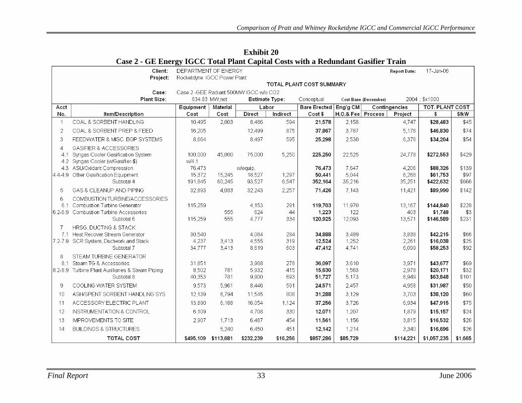
3.4 Economic Results The capital and operating costs results for Case 2, GE IGCC are shown in Exhibit 19 through Exhibit 23. The Total Plant Cost with a dual gasifier train is estimated to be 1,532 $/kW and 1,665 $/kW for a plant with a redundant three gasifier train. At 94% and 90% capacity factors, the Levelized Cost of Electricity for the redundant train arrangements are 52.5 and 54.3 mills/kWh, respectively. At 85% capacity factor, the LCOE for the dual train arrangement is 53.4 mills/kWh.
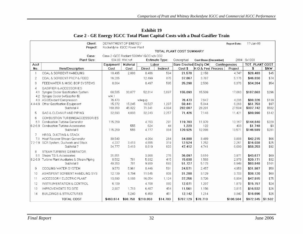
Comparison of Pratt and Whitney Rocketdyne IGCC and Commercial IGCC Performance
Exhibit 19 Case 2 - GE Energy IGCC Total Plant Capital Costs with a Dual Gasifier Train
Final Report 32 June 2006
Final Report 33 June 2006
Comparison of Pratt and Whitney Rocketdyne IGCC and Commercial IGCC Performance
Exhibit 20 Case 2 - GE Energy IGCC Total Plant Capital Costs with a Redundant Gasifier Train
Comparison of Pratt and Whitney Rocketdyne IGCC and Commercial IGCC Performance
Exhibit 21 Case 2 - GE Energy IGCC Capital Investment & Operating Cost Requirement Summary
(94% Capacity factor)
Final Report 34 June 2006

Comparison of Pratt and Whitney Rocketdyne IGCC and Commercial IGCC Performance
Exhibit 22 Case 2 - GE Energy IGCC Capital Investment & Operating Cost Requirement Summary
(90% Capacity factor)
Final Report 35 June 2006
Comparison of Pratt and Whitney Rocketdyne IGCC and Commercial IGCC Performance
Exhibit 23 Case 2 - GE Energy IGCC Capital Investment & Operating Cost Requirement Summary
(85% Capacity factor)
Final Report 36 June 2006
Comparison of Pratt and Whitney Rocketdyne IGCC and Commercial IGCC Performance
4 CASE 3 - PWR GASIFIER BASED IGCC PLANT DESCRIPTION AND RESULTS
Case 3 produces 613.7 MWe at 42.9% efficiency (7,957 BTU/kWh heat rate). The total plant cost excluding a spare gasification train is $743MM, which equates to a LCOE at 85% CF of 44.6 mills/kWh.
A block flow diagram and associated stream tables for the Case 3 PWR gasifier-based IGCC plant in syngas quench/convective syngas cooler heat recovery mode are presented in Exhibit 24 and Exhibit 25, respectively. Performance, capital costs and operating costs are presented in Exhibit 26 through Exhibit 30.
4.1 Process Description The Case 3 PWR IGCC plant consists of two compact gasifiers each fed with approximately 1,800 tpd of 95% oxygen produced via an on site Air Separation Unit (ASU) and approximately 2,500 tpd of Illinois #6 coal dried from 11.12% to 5% in a syngas/HRSG gas-fired coal dryer. The assumption that Illinois #6 coal has 5% inherent moisture has been made, but should be verified in the next stage of design. Each gasifier train in the PWR process requires approximately 140 tpd of pure nitrogen as coal transport gas as well as approximately 390 tpd of steam injection.
The PWR process claims an adiabatic flame temperature of ~2600°F, 1,000 psig operating pressure, and 100% carbon conversion. Approximately 490 tpd of slag (100% ash) is removed from the gasification reaction products (replicating the Case 4, Shell partial quench with recycle gas and convective cooling) followed with a candle filter and scrubber to separate the entrained slag. At this point, the syngas is heated to 400°F before entering a hydrolysis reactor, where >99% of the carbonyl sulfide is converted to hydrogen sulfide. The gas is cooled to ~100°F, is cleaned of ammonia and mercury prior to feeding the gas to the acid gas removal system.
A conventional Sulfinol-M process separates the syngas into an acid gas stream containing hydrogen sulfide and carbon dioxide and into a sweet gas stream containing the fuel gas to be combusted in the gas turbine. The acid gas stream is sent to a two bed Claus sulfur recovery plant with a tail gas clean up unit. Using approximately 113 tpd of 95% oxygen, the Claus process catalytically converts the gaseous sulfur compounds into elemental sulfur for collection and sale. A hydrogenation reactor converts the remaining gaseous sulfur dioxide into hydrogen sulfide, which may be separated from the tail gas in an MDEA tail gas treating unit. H2S is then recycled back to the Claus plant thermal reaction zone to improve overall sulfur recovery.
The clean synthesis gas stream exits the Sulfinol-M unit at approximately 125°F, where it is humidified with hot water at 370°F. The humidifier accomplishes some reheating of the syngas while partially diluting the gas for NOx mitigation in the gas turbine combustors. After sulfur removal, the sweet fuel gas is also depressurized through an expander from 695 psia to 380 psia to generate ~11 MWe of power.
Further reheating of the syngas, to 535°F, improves the gas turbine heat rate by reducing the amount of combustion energy used for heating the gas. In order to minimize NOx formation, the synthesis gas must be diluted to ~120 Btu/scf (LHV basis). Approximately 11,000 tpd of nitrogen diluent and 2,400 tpd of steam are added to accomplish the dilution. The resultant fuel
Final Report 37 June 2006
Comparison of Pratt and Whitney Rocketdyne IGCC and Commercial IGCC Performance
Final Report 38 June 2006
gas stream is combined with compressed and heated ambient air then combusted in two parallel General Electric 7FB model turbines.
The combustion products exiting the gas turbines are fed to a HRSG for heat recovery and additional power production before discharge to the atmosphere.
4.2 Modeling Assumptions for PWR Gasifier Refer to Section 2.2 for a detailed discussion on the modeling assumptions used for PWR gasifier performance prediction in this study.
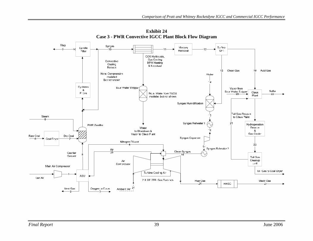
Comparison of Pratt and Whitney Rocketdyne IGCC and Commercial IGCC Performance
Exhibit 24 Case 3 - PWR Convective IGCC Plant Block Flow Diagram
Final Report 39 June 2006
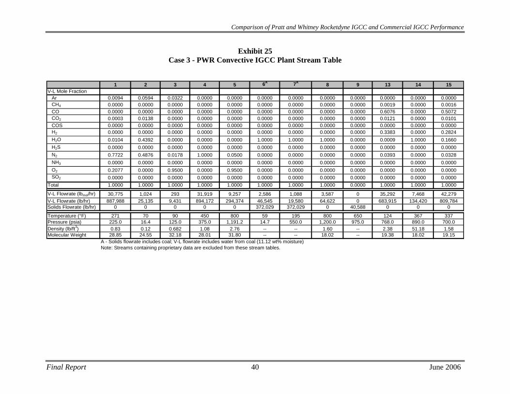
Comparison of Pratt and Whitney Rocketdyne IGCC and Commercial IGCC Performance
Exhibit 25 Case 3 - PWR Convective IGCC Plant Stream Table
1 2 3 4 5 6A 7A 8 9 13 14 15
V-L Mole FractionAr 0.0094 0.0594 0.0322 0.0000 0.0000 0.0000 0.0000 0.0000 0.0000 0.0000 0.0000 0.0000CH4 0.0000 0.0000 0.0000 0.0000 0.0000 0.0000 0.0000 0.0000 0.0000 0.0019 0.0000 0.0016CO 0.0000 0.0000 0.0000 0.0000 0.0000 0.0000 0.0000 0.0000 0.0000 0.6076 0.0000 0.5072CO2 0.0003 0.0138 0.0000 0.0000 0.0000 0.0000 0.0000 0.0000 0.0000 0.0121 0.0000 0.0101COS 0.0000 0.0000 0.0000 0.0000 0.0000 0.0000 0.0000 0.0000 0.0000 0.0000 0.0000 0.0000H2 0.0000 0.0000 0.0000 0.0000 0.0000 0.0000 0.0000 0.0000 0.0000 0.3383 0.0000 0.2824H2O 0.0104 0.4392 0.0000 0.0000 0.0000 1.0000 1.0000 1.0000 0.0000 0.0009 1.0000 0.1660H2S 0.0000 0.0000 0.0000 0.0000 0.0000 0.0000 0.0000 0.0000 0.0000 0.0000 0.0000 0.0000N2 0.7722 0.4876 0.0178 1.0000 0.0500 0.0000 0.0000 0.0000 0.0000 0.0393 0.0000 0.0328NH3 0.0000 0.0000 0.0000 0.0000 0.0000 0.0000 0.0000 0.0000 0.0000 0.0000 0.0000 0.0000O2 0.2077 0.0000 0.9500 0.0000 0.9500 0.0000 0.0000 0.0000 0.0000 0.0000 0.0000 0.0000SO2 0.0000 0.0000 0.0000 0.0000 0.0000 0.0000 0.0000 0.0000 0.0000 0.0000 0.0000 0.0000
Total 1.0000 1.0000 1.0000 1.0000 1.0000 1.0000 1.0000 1.0000 0.0000 1.0000 1.0000 1.0000
V-L Flowrate (lbmol/hr) 30,775 1,024 293 31,919 9,257 2,586 1,088 3,587 0 35,292 7,468 42,279V-L Flowrate (lb/hr) 887,988 25,135 9,431 894,172 294,374 46,545 19,580 64,622 0 683,915 134,420 809,784Solids Flowrate (lb/hr) 0 0 0 0 0 372,029 372,029 0 40,588 0 0 0
Temperature (°F) 271 70 90 450 800 59 195 800 650 124 367 337Pressure (psia) 225.0 16.4 125.0 375.0 1,191.2 14.7 550.0 1,200.0 975.0 768.0 890.0 700.0Density (lb/ft3) 0.83 0.12 0.682 1.08 2.76 -- -- 1.60 -- 2.38 51.18 1.58Molecular Weight 28.85 24.55 32.18 28.01 31.80 -- -- 18.02 -- 19.38 18.02 19.15
A - Solids flowrate includes coal; V-L flowrate includes water from coal (11.12 wt% moisture)Note: Streams containing proprietary data are excluded from these stream tables.
Final Report 40 June 2006
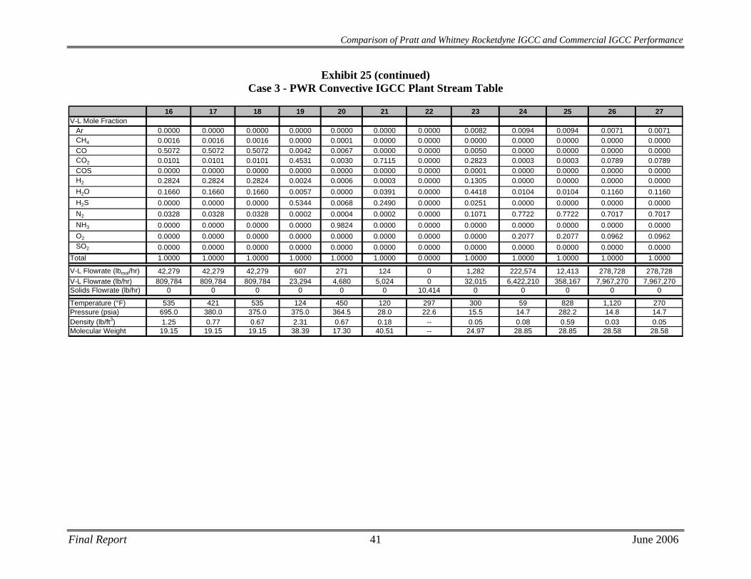
Final Report 41 June 2006
16 17 18 19 20 21 22 23 24 25 26 27V-L Mole Fraction
Ar 0.0000 0.0000 0.0000 0.0000 0.0000 0.0000 0.0000 0.0082 0.0094 0.0094 0.0071 0.0071CH4 0.0016 0.0016 0.0016 0.0000 0.0001 0.0000 0.0000 0.0000 0.0000 0.0000 0.0000 0.0000CO 0.5072 0.5072 0.5072 0.0042 0.0067 0.0000 0.0000 0.0050 0.0000 0.0000 0.0000 0.0000CO2 0.0101 0.0101 0.0101 0.4531 0.0030 0.7115 0.0000 0.2823 0.0003 0.0003 0.0789 0.0789COS 0.0000 0.0000 0.0000 0.0000 0.0000 0.0000 0.0000 0.0001 0.0000 0.0000 0.0000 0.0000H2 0.2824 0.2824 0.2824 0.0024 0.0006 0.0003 0.0000 0.1305 0.0000 0.0000 0.0000 0.0000H2O 0.1660 0.1660 0.1660 0.0057 0.0000 0.0391 0.0000 0.4418 0.0104 0.0104 0.1160 0.1160H2S 0.0000 0.0000 0.0000 0.5344 0.0068 0.2490 0.0000 0.0251 0.0000 0.0000 0.0000 0.0000N2 0.0328 0.0328 0.0328 0.0002 0.0004 0.0002 0.0000 0.1071 0.7722 0.7722 0.7017 0.7017NH3 0.0000 0.0000 0.0000 0.0000 0.9824 0.0000 0.0000 0.0000 0.0000 0.0000 0.0000 0.0000O2 0.0000 0.0000 0.0000 0.0000 0.0000 0.0000 0.0000 0.0000 0.2077 0.2077 0.0962 0.0962SO2 0.0000 0.0000 0.0000 0.0000 0.0000 0.0000 0.0000 0.0000 0.0000 0.0000 0.0000 0.0000
Total 1.0000 1.0000 1.0000 1.0000 1.0000 1.0000 0.0000 1.0000 1.0000 1.0000 1.0000 1.0000
V-L Flowrate (lbmol/hr) 42,279 42,279 42,279 607 271 124 0 1,282 222,574 12,413 278,728 278,728V-L Flowrate (lb/hr) 809,784 809,784 809,784 23,294 4,680 5,024 0 32,015 6,422,210 358,167 7,967,270 7,967,270Solids Flowrate (lb/hr) 0 0 0 0 0 0 10,414 0 0 0 0 0
Temperature (°F) 535 421 535 124 450 120 297 300 59 828 1,120 270Pressure (psia) 695.0 380.0 375.0 375.0 364.5 28.0 22.6 15.5 14.7 282.2 14.8 14.7Density (lb/ft3) 1.25 0.77 0.67 2.31 0.67 0.18 -- 0.05 0.08 0.59 0.03 0.05Molecular Weight 19.15 19.15 19.15 38.39 17.30 40.51 -- 24.97 28.85 28.85 28.58 28.58
Comparison of Pratt and Whitney Rocketdyne IGCC and Commercial IGCC Performance
Exhibit 25 (continued) Case 3 - PWR Convective IGCC Plant Stream Table
Comparison of Pratt and Whitney Rocketdyne IGCC and Commercial IGCC Performance
4.3 Equipment Descriptions
Coal Preparation and Feed Systems The coal as received contains 11.12 percent moisture, and must be dried to 5 percent or less moisture. The coal is simultaneously crushed and dried using a combination of Claus tail gas and air. Crushed and dried coal is delivered to a surge hopper with an approximate 2-hour capacity.
The coal is drawn from the surge hoppers and fed through a developmental proprietary dry coal feed pump system, which uses nitrogen to convey the coal to the gasifiers.
Air Separation Unit The air separation plant is designed to produce a nominal output of 3,700 tons/day of 95 percent pure O2 from two ASU production trains. Most of the oxygen is used in the gasifier. A small portion, approximately 110 tons/day, is used in the Claus plant. The air compressor is powered by an electric motor. Approximately 11,000 tons/day of nitrogen are also recovered, compressed, and used as dilution in the gas turbine combustor.
Gasifier
The PWR gasifier uses a plug-flow entrained reactor and a multi-port injection nozzle to increase the kinetics and conversion of the gasification reaction. The PWR gasification process gasifies dried coal with steam and 95% (by volume) oxygen at ~2600°F and 1,000 psia. The PWR process claims a 100% carbon conversion and faster kinetics allowing for a more compact gasifier design. The prototype reactor designed to process 3,000 tons of dried coal per day is anticipated to be 39 inches in diameter and 15 feet in length. The amount of dried coal processed in this study is approximately 5,000 tons per day.
Syngas Cooling High-temperature cooling heat recovery in each gasifier train is accomplished in two steps. The product gas from the gasifier is cooled to ~1650°F by adding cooled recycled fuel gas to lower the temperature below the ash melting point. Gas then goes through a convective raw gas cooler, which lowers the gas temperature from ~1650°F to 650°F, and produces high-pressure steam for use in the steam cycle. Boiler feedwater in the tube walls is saturated, and then steam and water are separated in a steam drum. Approximately 1.1 MMlb/hour of saturated steam at 1800 psia is produced. This steam then forms part of the general heat recovery system that provides steam to the steam turbine.
Particulate Removal A candle filter is used to remove any particulate material exiting the secondary gasification zone. The filter is comprised of an array of ceramic candle elements in a pressure vessel. The filter is cleaned by periodically back pulsing it with fuel gas to remove the fines material.
Final Report 42 June 2006
Comparison of Pratt and Whitney Rocketdyne IGCC and Commercial IGCC Performance
Synthesis Gas Recycle Compressor
A fraction of the raw gas from the filter is recycled back to the gasifier as quench gas. A single-stage compressor is utilized to boost the pressure of a cooled fuel gas stream and provide quench gas to cool the gas stream from the gasifier.
Syngas Scrubbing The “sour” gas leaving the particulate filter system consists mostly of hydrogen, CO2, CO, water vapor, nitrogen, and smaller quantities of methane, carbonyl sulfide (COS), H2S, and NH3.
The sour gas is cooled to 95ºF before H2S is removed. The cooling is accomplished by several heat exchangers, where water in the syngas condenses; the condensate contains NH3 and some of the H2S and CO2. The sour condensate is sent to water treatment.
The raw synthesis gas exiting the ceramic particulate filter then enters the scrubber for particulate removal at 450°F. The quench scrubber washes the syngas in a counter-current flow in two packed beds. After leaving the scrubber at a temperature of 310ºF, the gas has a residual soot content of less than 1 mg/m3. The quench scrubber removes essentially all traces of entrained particles, principally unconverted carbon, slag, and metals. The bottoms from the scrubber are sent to the slag removal and handling system for processing.
The syngas enters the syngas scrubber and is directed downwards by a dip tube into a water sump at the bottom of the syngas scrubber. Most of the solids are separated from the syngas at the bottom of the dip tube as the syngas goes upwards through the water. From the overhead of the syngas scrubber, the syngas enters the low-temperature gas cooling section for further cooling.
The slag handling system removes solids from the gasification process equipment. These solids normally consist of a small amount of unconverted carbon and essentially all of the ash contained in the feed coal. For this study, 100% carbon conversion was assumed. As a result, the “slag” is 100% ash. These solids are in the form of glass, which is non-leaching and fully encapsulates any metals.
COS Hydrolysis / Low Temperature Gas Cooling
H2S and COS are at significant concentrations, requiring removal for the power plant to achieve the low design level of SO2 emissions. H2S is removed in an acid gas removal process; however, because COS is not readily removable, it is first catalytically converted to H2S in a COS hydrolysis unit.
Following the quench/scrubber system, the gas is reheated to 400°F and fed to the COS hydrolysis reactor. The COS is hydrolyzed with steam in the gas over a catalyst bed to H2S, which is more easily removed by the AGR solvent. Any HCN in the syngas will also be reacted in the COS hydrolysis unit.
Before the raw fuel gas can be treated in the AGR process, it must be cooled to about 100°F. During this cooling through a series of heat exchangers, part of the water vapor condenses. This water, which contains some NH3, is sent to the wastewater treatment section.
Final Report 43 June 2006
Comparison of Pratt and Whitney Rocketdyne IGCC and Commercial IGCC Performance
Mercury Removal
Mercury removal was based on packed beds of sulfur-impregnated carbon similar to what has been used at Eastman Chemical’s gasification plant. Dual beds of sulfur-impregnated carbon with approximately a 20-second superficial gas residence time of should achieve >90 percent reduction of mercury in addition to removal of other volatile heavy metals such as arsenic.
Acid Gas Removal
The Sulfinol process, developed by Shell in the early 1960s, is a combination process that uses a mixture of amines and a physical solvent. The solvent consists of an aqueous amine and sulfolane. Sulfinol-D uses diisopropanolamine (DIPA), while Sulfinol-M uses MDEA. The mixed solvents allow for better solvent loadings at high acid gas partial pressures and higher solubility of COS and organic sulfur compounds than straight aqueous amines. Sulfinol-M was selected for this application.
The acid gas stream, consisting of hydrogen sulfide and carbon dioxide, is separated from the syngas by physical and chemical absorption in the Sulfinol solvent. The rich Sulfinol solvent is regenerated in a stripping column and is then recycled back to the absorber as lean solvent in a continuous loop. The stripping column feeds the acid gas taken from the Sulfinol solvent to the Claus plant for sulfur recovery.
Sour Water Stripper The sour water stripper removes NH3, H2S, and other impurities from the waste stream of the scrubber and water condensed in the low temperature gas cooling section. The sour gas stripper consists of a sour drum that accumulates sour water from the gas scrubber and condensate from syngas coolers. Sour water from the drum flows to the sour stripper, which consists of a packed column with a steam-heated reboiler. Sour gas is stripped from the liquid and sent to the sulfur recovery unit. Remaining water is sent to wastewater treatment.
Sulfur Recovery System
The sulfur recovery unit is a Claus bypass type sulfur recovery unit utilizing oxygen instead of air followed by a SCOT tail gas unit. The Claus plant produces molten sulfur by reacting approximately one third of the H2S in the feed to SO2, then reacting the H2S and SO2 to sulfur and water. The combination of Claus technology and SCOT tail gas technology will result in a sulfur recovery exceeding 99 percent of that fed to the Claus plant and a vent gas of less than 2 ppmv of SO2.
Utilizing oxygen instead of air in the Claus plant reduces the overall cost of the sulfur recovery plant. The sulfur plant will produce approximately 112 long tons of elemental sulfur per day. Feed for this case consists of acid gas from both acid gas cleanup units and a vent stream from the sour water stripper in the gasifier section. Vent gas from the tail gas treatment unit is vented to the coal dryer, contributing to total plant sulfur emissions of less than 0.033 lb/MMBtu, meeting air quality standards.
Final Report 44 June 2006
Comparison of Pratt and Whitney Rocketdyne IGCC and Commercial IGCC Performance
Syngas Expander
After sulfur removal, the sweet fuel gas is saturated with condensate, reheated, and depressurized through an expander from 695 psia to 380 psia, which is near the pressure required by the gas turbine. The expander generates ~11 MWe of power.
Gas Turbine Generator Both of the combustion turbine generators are General Electric 7FB model turbines modified for syngas firing. The maximum output of each is expected to be 232 MW, based on the rotor torque limit. Each machine is an axial flow, single spool, constant speed unit, equipped with variable inlet guide vanes and syngas version of diffusion-flame combustor with nitrogen diluent injection. The turbine exhaust gases are conveyed through a HRSG to recover the large quantities of thermal energy that remain.
The gas turbine generator selected for this application is based on a natural gas fired 7FB machine. In this service, with syngas from an IGCC plant, the machine requires some modifications to the burner and turbine nozzles in order to properly combust the medium-Btu gas and expand the combustion products in the turbine section of the machine. A reduction in rotor inlet temperature of about 50°F is expected, relative to a production model 7FB machine firing natural gas. This temperature reduction may be necessary to not exceed design basis gas path temperatures throughout the expander. If the first-stage rotor inlet temperature were maintained at the design value, gas path temperatures downstream of the inlet to the first (HP) turbine stage may increase, relative to natural-gas-fired temperatures, due to gas property changes.
The syngas fired 7FB gas turbine is a developmental machine that GE expects to have available in the 2010 time frame for commercial applications.
Heat Recovery Steam Generator / Steam Turbine The HRSG supplies steam to a steam turbine generator which is a tandem compound, two-flow exhaust, single reheat, condensing, GE model D-11, or equal. The steam turbine consists of an HP section, an IP section, and one double-flow LP section, all connected to the generator by a common shaft. The HP and IP sections are contained in a single-span, opposed-flow casing, with the double-flow LP section in a separate casing. The overall power output from the steam turbine is 240 MWe.
4.4 Performance Results For Case 3, the combustion turbines are two General Electric 7FB model turbines in parallel, each producing 232 MWe for a total of 464 MWe. The steam turbine produces 240 MWe, and the sweet gas expander produces 11 MWe. Total auxiliary power required is 101 MWe, yielding a net plant power output of 614 MWe.
Overall plant efficiency (HHV) is 42.9%, with a heat rate of 7,957 Btu/kWh.
The performance results are summarized in Exhibit 26.
Final Report 45 June 2006
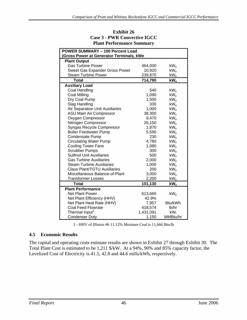
Comparison of Pratt and Whitney Rocketdyne IGCC and Commercial IGCC Performance
Final Report 46 June 2006
Exhibit 26 Case 3 - PWR Convective IGCC
Plant Performance Summary POWER SUMMARY – 100 Percent Load (Gross Power at Generator Terminals, kWe
Plant Output Gas Turbine Power 464,000 kWeSweet Gas Expander Gross Power 10,920 kWeSteam Turbine Power 239,870 kWe
Total 714,790 kWe
Auxiliary Load Coal Handling 540 kWeCoal Milling 1,090 kWeDry Coal Pump 1,500 kWeSlag Handling 330 kWeAir Separation Unit Auxiliaries 1,000 kWeASU Main Air Compressor 38,300 kWeOxygen Compressor 9,470 kWeNitrogen Compressor 26,150 kWeSyngas Recycle Compressor 1,870 kWeBoiler Feedwater Pump 5,590 kWeCondensate Pump 230 kWeCirculating Water Pump 4,780 kWeCooling Tower Fans 1,080 kWeScrubber Pumps 300 kWeSulfinol Unit Auxiliaries 500 kWeGas Turbine Auxiliaries 2,000 kWeSteam Turbine Auxiliaries 1,000 kWeClaus Plant/TGTU Auxiliaries 200 kWeMiscellaneous Balance-of-Plant 3,000 kWeTransformer Losses 2,200 kWe
Total 101,130 kWe
Plant Performance Net Plant Power 613,660 kWeNet Plant Efficiency (HHV) 42.9% Net Plant Heat Rate (HHV) 7,957 Btu/kWh Coal Feed Flowrate 418,574 lb/hr Thermal Input1 1,431,091 kWtCondenser Duty 1,150 MMBtu/hr
1 - HHV of Illinois #6 11.12% Moisture Coal is 11,666 Btu/lb
4.5 Economic Results The capital and operating costs estimate results are shown in Exhibit 27 through Exhibit 30. The Total Plant Cost is estimated to be 1,211 $/kW. At a 94%, 90% and 85% capacity factor, the Levelized Cost of Electricity is 41.5, 42.8 and 44.6 mills/kWh, respectively.

Final Report 47 June 2006
Comparison of Pratt and Whitney Rocketdyne IGCC and Commercial IGCC Performance
Exhibit 27 Case 3 - PWR Convective IGCC Total Plant Capital Costs
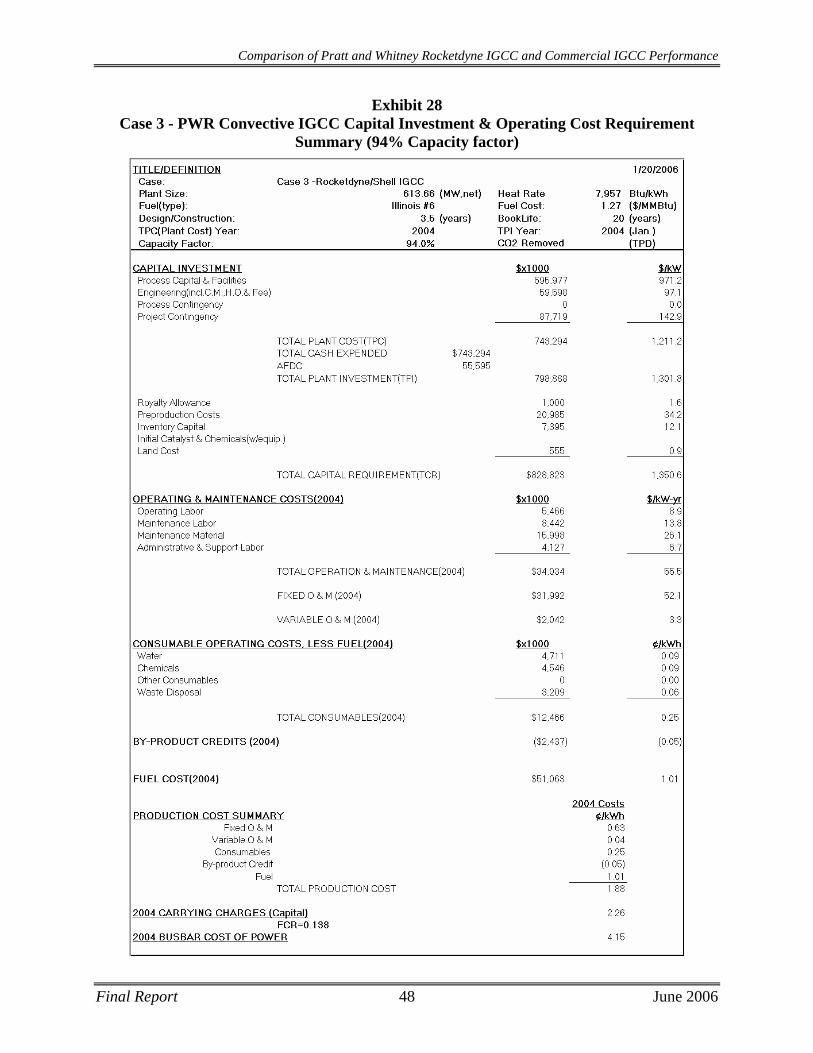
Comparison of Pratt and Whitney Rocketdyne IGCC and Commercial IGCC Performance
Exhibit 28 Case 3 - PWR Convective IGCC Capital Investment & Operating Cost Requirement
Summary (94% Capacity factor)
Final Report 48 June 2006

Comparison of Pratt and Whitney Rocketdyne IGCC and Commercial IGCC Performance
Exhibit 29 Case 3 - PWR Convective IGCC Capital Investment & Operating Cost Requirement
Summary (90% Capacity factor)
Final Report 49 June 2006

Comparison of Pratt and Whitney Rocketdyne IGCC and Commercial IGCC Performance
Exhibit 30 Case 3 - PWR Convective IGCC Capital Investment & Operating Cost Requirement
Summary (85% Capacity factor)
Final Report 50 June 2006
Comparison of Pratt and Whitney Rocketdyne IGCC and Commercial IGCC Performance
5 CASE 4 - SHELL GASIFIER BASED IGCC PLANT DESCRIPTION AND RESULTS
Case 4 produces 624.6 MWe at 42.0% efficiency (8,130 BTU/kWh heat rate). The plant costs $949MM and, at 85% CF, provides electricity at 52.8 mills/kWh. A plant with a redundant gasifier train costs $1,045MM and at 90% CF, provides electricity at 54.2 mills/kWh, and at 94% CF, provides electricity at 52.5 mills/kWh
A block flow diagram and associated stream tables for the Case 4 Shell gasifier-based IGCC plant in syngas quench/convective syngas cooling heat recovery mode are presented in Exhibit 31 and Exhibit 32, respectively. Performance, capital costs and operating costs are presented in Exhibit 33 through Exhibit 38.
5.1 Process Description Case 4 is similar to Case 3 with the following exception:
• The gasifier used in Case 4 is the Shell Gasifier with an operating pressure of 465 psia.
This IGCC plant design is based on the Shell Global Solutions gasification technology, which utilizes a pressurized entrained-flow dry-feed gasifier to meet the syngas fuel requirements for two General Electric 7FB combustion turbines. The ASU supplies 95 percent pure oxygen to the gasifier.
The pressurized entrained-flow Shell gasifier uses a dry-coal feed and oxygen to produce a medium heating value fuel gas. The syngas produced in the gasifier at about 2700°F is quenched to around 1650°F by cooled recycled syngas. The syngas passes through a convective cooler and leaves near 650°F. High-pressure saturated steam is generated in the syngas cooler and is joined with the main steam supply.
Raw gas leaving the syngas cooler is cleaned of particulate matter and passes through a COS hydrolysis reactor before entering a Sulfinol-M acid gas removal process. Elemental sulfur is produced as a salable byproduct. The clean gas exiting the AGR system is conveyed to the combustion turbines where it serves as fuel for the combustion turbine/HRSG/steam turbine power conversion system. The exhaust gas from the combustion turbine and HRSG is released to the atmosphere via a conventional stack.
This plant utilizes a combined cycle for combustion of the medium-Btu gas from the gasifier to generate electric power. A Brayton cycle using air and combustion products as working fluid is used in conjunction with a conventional subcritical steam Rankine cycle. The two cycles are coupled by generation of steam in the HRSG, by feedwater heating in the HRSG, and by heat recovery from the IGCC process (gas cooling modules).
The hot combustion gases are conveyed to the inlet of the turbine section, where they enter and expand through the turbine to produce power to drive the compressor and electric generator. The turbine exhaust gases are conveyed through a HRSG to recover the large quantities of thermal energy that remain. The HRSG exhausts to a separate stack.
The steam cycle is based on maximizing heat recovery from the gas turbine exhaust gas, as well as utilizing steam generation opportunities in the gasifier process. As the turbine exhaust gas passes through the HRSG, it progressively transfers heat for reheating steam (cold reheat to hot
Final Report 51 June 2006
Comparison of Pratt and Whitney Rocketdyne IGCC and Commercial IGCC Performance
Final Report 52 June 2006
reheat), superheating main steam, and generating main steam in an HP drum. The HRSG also generates and superheats steam from an IP drum (as reheat, and for use in the integral deaerator), and heats feedwater.
The steam turbine selected to match this cycle is a two-casing, reheat, double-flow (exhaust) machine, exhausting downward to the condenser. The HP and IP turbine sections are contained in one casing, with the LP section in a second casing.
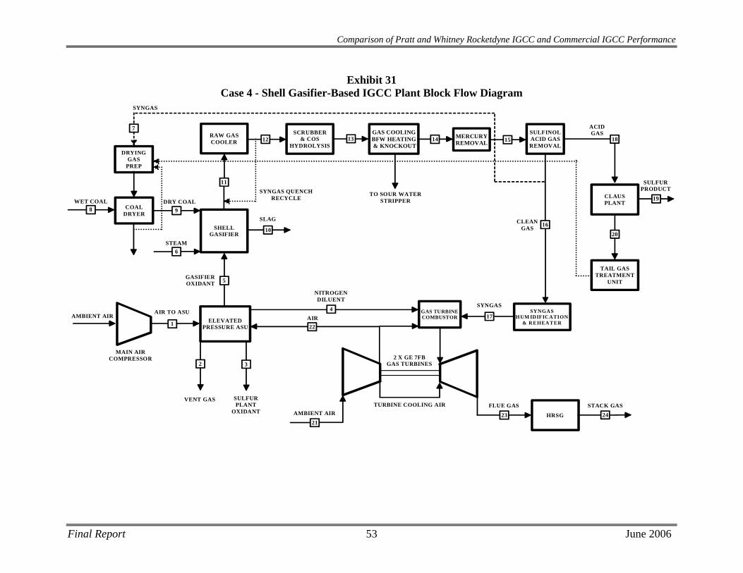
Comparison of Pratt and Whitney Rocketdyne IGCC and Commercial IGCC Performance
Exhibit 31 Case 4 - Shell Gasifier-Based IGCC Plant Block Flow Diagram
SHELLGASIFIER
ELEVATEDPRESSURE ASU
RAW GASCOOLER
GAS COOLINGBFW HEATING & KNOCKOUT
TAIL GAS TREATMENT
UNIT
CLAUSPLANT
SCRUBBER& COS
HYDROLYSIS
5GASIFIEROXIDANT
10
SLAG
AIR TO ASU
VENT GAS
1
2
11
12 18
20
17
19
SULFURPRODUCT
13
HRSG
2 X GE 7FBGAS TURBINES
2123 24AMBIENT AIR
TURBINE COOLING AIR FLUE GAS STACK GAS
SULFINOLACID GASREMOVAL
SULFURPLANT
OXIDANT
3
GAS TURBINECOMBUSTOR
14
SYNGAS
NITROGENDILUENT
4
16
SYNGASHUM IDIFICATION
& REHEATER
ACIDGAS
CLEANGAS
22AIR
MERCURYREMOVAL 15
SYNGAS QUENCHRECYCLE
TO SOUR WATERSTRIPPERDRY COAL
9
STEAM6
COALDRYER
WET COAL8
DRYINGGAS
PREP
SYNGAS
7
MAIN AIRCOMPRESSOR
AMBIENT AIR
Final Report 53 June 2006
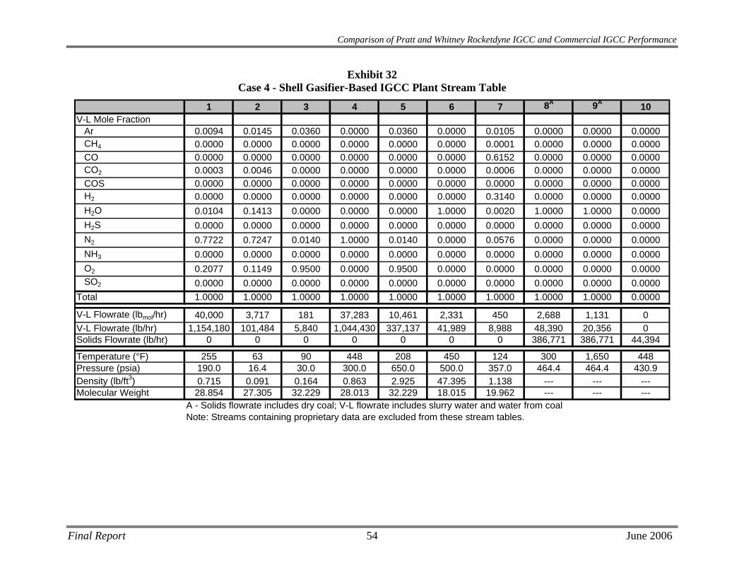
Comparison of Pratt and Whitney Rocketdyne IGCC and Commercial IGCC Performance
Exhibit 32 Case 4 - Shell Gasifier-Based IGCC Plant Stream Table
1 2 3 4 5 6 7 8A 9A 10V-L Mole Fraction
Ar 0.0094 0.0145 0.0360 0.0000 0.0360 0.0000 0.0105 0.0000 0.0000 0.0000CH4 0.0000 0.0000 0.0000 0.0000 0.0000 0.0000 0.0001 0.0000 0.0000 0.0000CO 0.0000 0.0000 0.0000 0.0000 0.0000 0.0000 0.6152 0.0000 0.0000 0.0000CO2 0.0003 0.0046 0.0000 0.0000 0.0000 0.0000 0.0006 0.0000 0.0000 0.0000COS 0.0000 0.0000 0.0000 0.0000 0.0000 0.0000 0.0000 0.0000 0.0000 0.0000H2 0.0000 0.0000 0.0000 0.0000 0.0000 0.0000 0.3140 0.0000 0.0000 0.0000H2O 0.0104 0.1413 0.0000 0.0000 0.0000 1.0000 0.0020 1.0000 1.0000 0.0000H2S 0.0000 0.0000 0.0000 0.0000 0.0000 0.0000 0.0000 0.0000 0.0000 0.0000N2 0.7722 0.7247 0.0140 1.0000 0.0140 0.0000 0.0576 0.0000 0.0000 0.0000NH3 0.0000 0.0000 0.0000 0.0000 0.0000 0.0000 0.0000 0.0000 0.0000 0.0000O2 0.2077 0.1149 0.9500 0.0000 0.9500 0.0000 0.0000 0.0000 0.0000 0.0000SO2 0.0000 0.0000 0.0000 0.0000 0.0000 0.0000 0.0000 0.0000 0.0000 0.0000
Total 1.0000 1.0000 1.0000 1.0000 1.0000 1.0000 1.0000 1.0000 1.0000 0.0000
V-L Flowrate (lbmol/hr) 40,000 3,717 181 37,283 10,461 2,331 450 2,688 1,131 0V-L Flowrate (lb/hr) 1,154,180 101,484 5,840 1,044,430 337,137 41,989 8,988 48,390 20,356 0Solids Flowrate (lb/hr) 0 0 0 0 0 0 0 386,771 386,771 44,394
Temperature (°F) 255 63 90 448 208 450 124 300 1,650 448Pressure (psia) 190.0 16.4 30.0 300.0 650.0 500.0 357.0 464.4 464.4 430.9Density (lb/ft3) 0.715 0.091 0.164 0.863 2.925 47.395 1.138 --- --- ---Molecular Weight 28.854 27.305 32.229 28.013 32.229 18.015 19.962 --- --- ---
A - Solids flowrate includes dry coal; V-L flowrate includes slurry water and water from coalNote: Streams containing proprietary data are excluded from these stream tables.
Final Report 54 June 2006
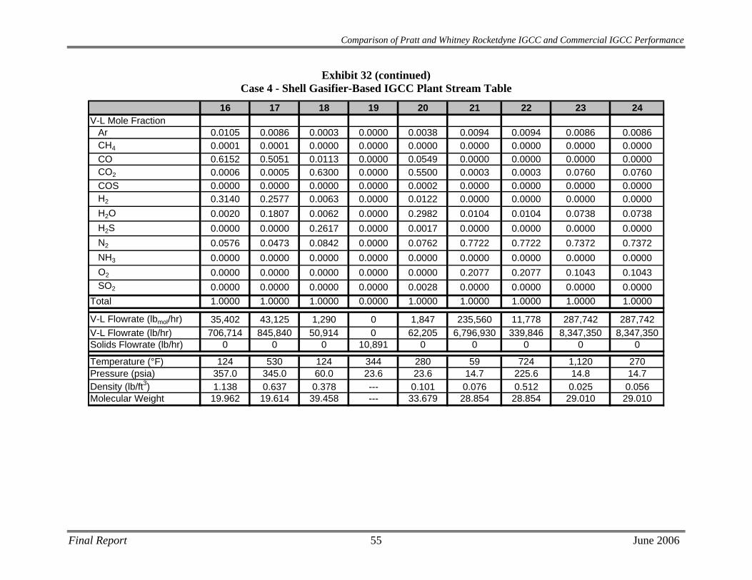
Final Report 55 June 2006
Comparison of Pratt and Whitney Rocketdyne IGCC and Commercial IGCC Performance
16 17 18 19 20 21 22 23 24V-L Mole Fraction
Ar 0.0105 0.0086 0.0003 0.0000 0.0038 0.0094 0.0094 0.0086 0.0086CH4 0.0001 0.0001 0.0000 0.0000 0.0000 0.0000 0.0000 0.0000 0.0000CO 0.6152 0.5051 0.0113 0.0000 0.0549 0.0000 0.0000 0.0000 0.0000CO2 0.0006 0.0005 0.6300 0.0000 0.5500 0.0003 0.0003 0.0760 0.0760COS 0.0000 0.0000 0.0000 0.0000 0.0002 0.0000 0.0000 0.0000 0.0000H2 0.3140 0.2577 0.0063 0.0000 0.0122 0.0000 0.0000 0.0000 0.0000H2O 0.0020 0.1807 0.0062 0.0000 0.2982 0.0104 0.0104 0.0738 0.0738H2S 0.0000 0.0000 0.2617 0.0000 0.0017 0.0000 0.0000 0.0000 0.0000N2 0.0576 0.0473 0.0842 0.0000 0.0762 0.7722 0.7722 0.7372 0.7372NH3 0.0000 0.0000 0.0000 0.0000 0.0000 0.0000 0.0000 0.0000 0.0000O2 0.0000 0.0000 0.0000 0.0000 0.0000 0.2077 0.2077 0.1043 0.1043SO2 0.0000 0.0000 0.0000 0.0000 0.0028 0.0000 0.0000 0.0000 0.0000
Total 1.0000 1.0000 1.0000 0.0000 1.0000 1.0000 1.0000 1.0000 1.0000
V-L Flowrate (lbmol/hr) 35,402 43,125 1,290 0 1,847 235,560 11,778 287,742 287,742V-L Flowrate (lb/hr) 706,714 845,840 50,914 0 62,205 6,796,930 339,846 8,347,350 8,347,350Solids Flowrate (lb/hr) 0 0 0 10,891 0 0 0 0 0
Temperature (°F) 124 530 124 344 280 59 724 1,120 270Pressure (psia) 357.0 345.0 60.0 23.6 23.6 14.7 225.6 14.8 14.7Density (lb/ft3) 1.138 0.637 0.378 --- 0.101 0.076 0.512 0.025 0.056Molecular Weight 19.962 19.614 39.458 --- 33.679 28.854 28.854 29.010 29.010
Exhibit 32 (continued) Case 4 - Shell Gasifier-Based IGCC Plant Stream Table
Comparison of Pratt and Whitney Rocketdyne IGCC and Commercial IGCC Performance
5.2 Equipment Descriptions
Coal Preparation and Feed Systems The coal as received contains 11.12 percent moisture, and must be dried to 5 percent or less moisture. The coal is simultaneously crushed and dried. Crushed and dried coal is delivered to a surge hopper with an approximate 2-hour capacity.
The coal is drawn from the surge hoppers and fed through a pressurization lock hopper system to a dense phase pneumatic conveyor, which uses nitrogen to convey the coal to the gasifiers.
Air Separation Unit The air separation plant is designed to produce a nominal output of 4,100 tpd of 95 percent pure O2 from two ASU production trains. Most of the oxygen is used in the gasifier. A small portion, approximately 70 tpd, is used in the Claus plant. The air compressor is powered by an electric motor. Approximately 12,500 tpd of nitrogen are also recovered, compressed, and used as dilution in the gas turbine combustor.
Gasifier There are two Shell entrained-flow gasifiers, operating at 465 psia each processing 2,440 tons per day of dry coal. Sized coal is stored in surge hoppers, which serve as a reserve of raw material for the pressurization lock hoppers below. Coal is pressurized and fluidized with nitrogen, and transported to horizontally opposed burners on each gasifier along with 240 tpd steam, 2,020 tpd oxygen and recirculated solids from the raw gas filter. Gas exits the gasifier at 1650°F, and contains elutriated particulate matter. The gas passes through the raw gas cooler and then through the raw gas filter in which a majority of the fine particles are removed and are returned to the gasifier with the coal fuel.
Fines produced by the gasification system are recirculated to extinction. The ash that is not carried out with the gas forms slag and runs down the interior walls, exiting the gasifier in liquid form. The slag is solidified in a quench tank for disposal. A pressure reduction system is used to reduce the pressure of the solids from 465 to 15 psia.
Syngas Cooling High-temperature cooling heat recovery in each gasifier train is accomplished in two steps. The product gas from the gasifier is cooled to 1650°F by adding cooled recycled fuel gas to lower the temperature below the ash melting point. Gas then goes through a raw gas cooler, which lowers the gas temperature from 1650°F to 650°F, and produces high-pressure steam for use in the steam cycle.
Hot raw gas after quenching from the gasification zone exits the gasifier and is cooled to 650ºF in a convective cooler. The waste heat from this cooling is used to generate high-pressure steam. Boiler feedwater in the tube walls is saturated, and then steam and water are separated in a steam drum. Approximately 830,000 lb/hour of saturated steam at 1800 psia is produced. This steam then forms part of the general heat recovery system that provides steam to the steam turbine.
Final Report 56 June 2006
Comparison of Pratt and Whitney Rocketdyne IGCC and Commercial IGCC Performance
Particulate Removal
A candle filter is used to remove any particulate material exiting the secondary gasification zone. This material, char and fly ash, is recycled back to the gasifier. The filter is comprised of an array of ceramic candle elements in a pressure vessel. The filter is cleaned by periodically back pulsing it with fuel gas to remove the fines material. Raw gas exits the candle filter at 448ºF and 431 psia.
Syngas Recycle Compressor A fraction of the raw gas from the filter is recycled back to the gasifier as quench gas. A single-stage compressor is utilized to boost the pressure of a cooled fuel gas stream from 431 psia to 470 psia to provide quench gas to cool the gas stream from the gasifier.
Syngas Scrubbing
The “sour” gas leaving the particulate filter system consists mostly of hydrogen, CO2, CO, water vapor, nitrogen, and smaller quantities of methane, carbonyl sulfide (COS), H2S, and NH3.
The sour gas is cooled to 95ºF before H2S is removed. The cooling is accomplished by several heat exchangers, where water in the syngas condenses; the condensate contains NH3 and some of the H2S and CO2. The sour condensate is sent to water treatment.
The raw synthesis gas exiting the ceramic particulate filter at 448°F then enters the scrubber for particulate removal. The quench scrubber washes the syngas in a counter-current flow in two packed beds. After leaving the scrubber at a temperature of 230ºF, the gas has a residual soot content of less than 1 mg/m3. The quench scrubber removes essentially all traces of entrained particles, principally unconverted carbon, slag, and metals. The bottoms from the scrubber are sent to the slag removal and handling system for processing.
COS Hydrolysis Refer to Case 3 in section 4.3 for a description of the COS Hydrolysis system used in Case 4, since they are similar.
Mercury Removal Refer to Case 3 in section 4.3 for a description of the Mercury Removal system used in Case 4, since they are similar.
Acid Gas Removal Refer to Case 3 in section 4.3 for a description of the Acid Gas Removal system used in Case 4, since they are similar.
Sour Water Stripper Refer to Case 3 in section 4.3 for a description of the Acid Gas Removal system used in Case 4, since they are similar.
Final Report 57 June 2006
Comparison of Pratt and Whitney Rocketdyne IGCC and Commercial IGCC Performance
Sulfur Recovery System
The sulfur recovery unit is a Claus bypass type sulfur recovery unit utilizing oxygen instead of air followed by a SCOT tail gas unit. The Claus plant produces molten sulfur by reacting approximately one third of the H2S in the feed to SO2, then reacting the H2S and SO2 to sulfur and water. The combination of Claus technology and SCOT tail gas technology will result in an overall sulfur recovery exceeding 99 percent and a vent gas of less than 2 ppmv of SO2.
Utilizing oxygen instead of air in the Claus plant reduces the overall cost of the sulfur recovery plant. The sulfur plant will produce approximately 117 long tons of elemental sulfur per day. Feed for this case consists of acid gas from both acid gas cleanup units and a vent stream from the sour water stripper in the gasifier section. Vent gas from the tail gas treatment unit is vented to the coal dryer.
Gas Turbine Generator Refer to Case 3 in section 4.3 for a description of the Gas Turbine Generator used in Case 4, since they are similar.
Heat Recovery Steam Generator / Steam Turbine
Refer to Case 3 in section 4.3 for a description of the HRSG and Steam Turbine used in Case 4, since they are similar. The overall power output from the steam turbine is 270.4 MWe.
5.3 Performance Results For Case 4, the combustion turbines are two General Electric Model 7FB turbines in parallel, each producing 232 MWe for a total of 464 MWe. The steam turbine produces 270 MWe. Total auxiliary power required is 110 MWe, yielding a net plant power output of 625 MWe.
Overall plant efficiency (HHV) is 42.0%, with a heat rate of 8,130 Btu/kWh.
The performance results are summarized in Exhibit 33.
Final Report 58 June 2006
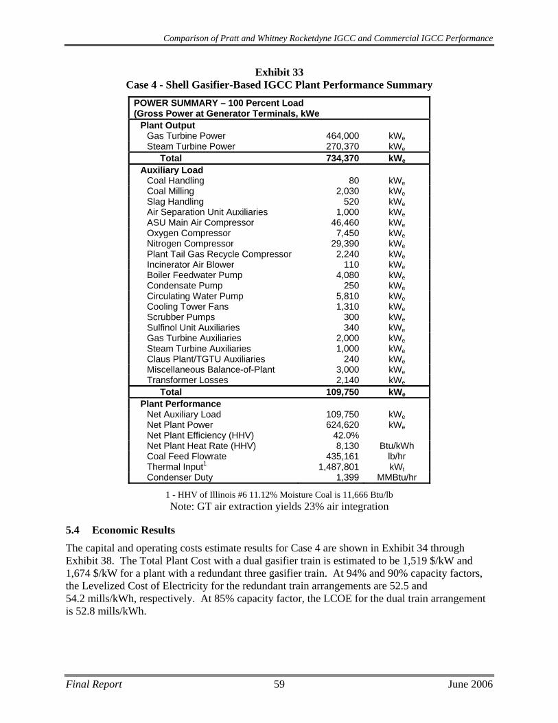
Comparison of Pratt and Whitney Rocketdyne IGCC and Commercial IGCC Performance
Final Report 59 June 2006
Exhibit 33 Case 4 - Shell Gasifier-Based IGCC Plant Performance Summary
POWER SUMMARY – 100 Percent Load (Gross Power at Generator Terminals, kWe
Plant Output Gas Turbine Power 464,000 kWeSteam Turbine Power 270,370 kWe
Total 734,370 kWe
Auxiliary Load Coal Handling 80 kWeCoal Milling 2,030 kWeSlag Handling 520 kWeAir Separation Unit Auxiliaries 1,000 kWeASU Main Air Compressor 46,460 kWeOxygen Compressor 7,450 kWeNitrogen Compressor 29,390 kWePlant Tail Gas Recycle Compressor 2,240 kWeIncinerator Air Blower 110 kWeBoiler Feedwater Pump 4,080 kWeCondensate Pump 250 kWeCirculating Water Pump 5,810 kWeCooling Tower Fans 1,310 kWeScrubber Pumps 300 kWeSulfinol Unit Auxiliaries 340 kWeGas Turbine Auxiliaries 2,000 kWeSteam Turbine Auxiliaries 1,000 kWeClaus Plant/TGTU Auxiliaries 240 kWeMiscellaneous Balance-of-Plant 3,000 kWeTransformer Losses 2,140 kWe
Total 109,750 kWe
Plant Performance Net Auxiliary Load 109,750 kWeNet Plant Power 624,620 kWeNet Plant Efficiency (HHV) 42.0% Net Plant Heat Rate (HHV) 8,130 Btu/kWh Coal Feed Flowrate 435,161 lb/hr Thermal Input1 1,487,801 kWtCondenser Duty 1,399 MMBtu/hr
1 - HHV of Illinois #6 11.12% Moisture Coal is 11,666 Btu/lb Note: GT air extraction yields 23% air integration
5.4 Economic Results The capital and operating costs estimate results for Case 4 are shown in Exhibit 34 through Exhibit 38. The Total Plant Cost with a dual gasifier train is estimated to be 1,519 $/kW and 1,674 $/kW for a plant with a redundant three gasifier train. At 94% and 90% capacity factors, the Levelized Cost of Electricity for the redundant train arrangements are 52.5 and 54.2 mills/kWh, respectively. At 85% capacity factor, the LCOE for the dual train arrangement is 52.8 mills/kWh.
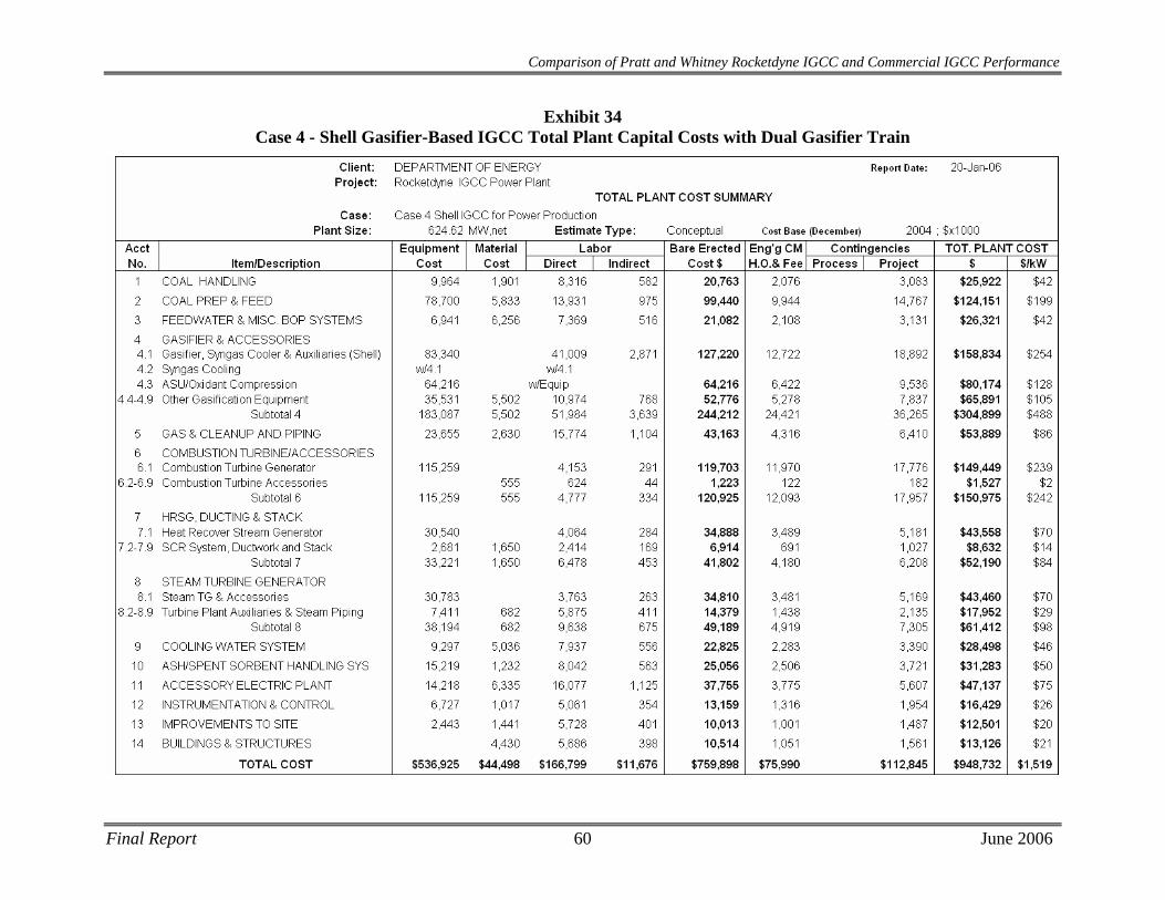
Comparison of Pratt and Whitney Rocketdyne IGCC and Commercial IGCC Performance
Exhibit 34 Case 4 - Shell Gasifier-Based IGCC Total Plant Capital Costs with Dual Gasifier Train
Final Report 60 June 2006
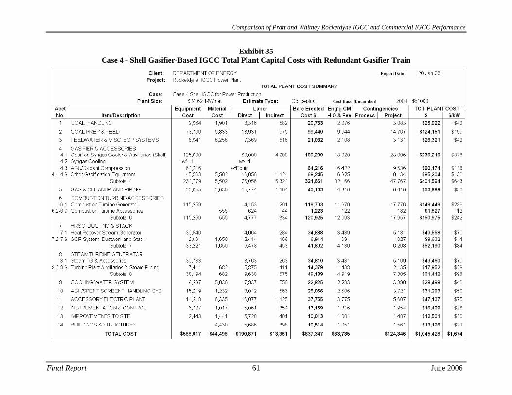
Final Report 61 June 2006
Comparison of Pratt and Whitney Rocketdyne IGCC and Commercial IGCC Performance
Exhibit 35 Case 4 - Shell Gasifier-Based IGCC Total Plant Capital Costs with Redundant Gasifier Train

Comparison of Pratt and Whitney Rocketdyne IGCC and Commercial IGCC Performance
Exhibit 36 Case 4 - Shell Gasifier-Based IGCC Capital Investment & Operating Cost Requirement
Summary (94% Capacity factor)
Final Report 62 June 2006
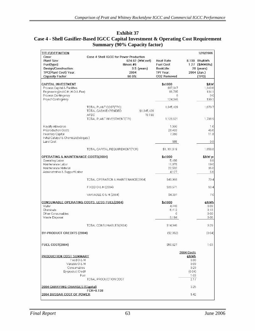
Comparison of Pratt and Whitney Rocketdyne IGCC and Commercial IGCC Performance
Exhibit 37 Case 4 - Shell Gasifier-Based IGCC Capital Investment & Operating Cost Requirement
Summary (90% Capacity factor)
Final Report 63 June 2006

Comparison of Pratt and Whitney Rocketdyne IGCC and Commercial IGCC Performance
Exhibit 38 Case 4 - Shell Gasifier-Based IGCC Capital Investment & Operating Cost Requirement
Summary (85% Capacity factor)
Final Report 64 June 2006
Comparison of Pratt and Whitney Rocketdyne IGCC and Commercial IGCC Performance
Final Report 65 June 2006
6 CASE 5 - PWR GASIFIER BASED H2 PRODUCTION PLANT DESCRIPTION AND RESULTS
Consuming 419,050 lb/hr of Illinois #6 coal, the PWR hydrogen production plant produces 56,179 lb/hr of 99.99%+ H2. The plant requires an additional 31 MWe of power from another source to meet a total auxiliary load of 117 MWe.
A block flow diagram and associated stream tables for the Case 5 PWR gasifier-based H2 production plant in partial quench mode are presented in Exhibit 39 and Exhibit 40, respectively.
6.1 Process Description The Case 5 PWR H2 production plant consists of two compact, partially quenched gasifiers each fed with approximately 1,800 tpd of 95% oxygen produced via an on site Air Separation Unit (ASU) and approximately 2,500 tpd of Illinois #6 coal dried from 11.12% to 5% in an AGR tail gas-fired coal dryer. It is assumed that Illinois #6 coal has 5% inherent moisture.
A proprietary PWR coal extrusion feed system is utilized for feeding dried coal to the PWR gasifier. Each train in the PWR process requires approximately 140 tpd of CO2 as coal transport gas as well as approximately 390 tpd of steam injection.
The PWR process claims an adiabatic flame temperature of ~2500°F, 1,000 psig operating pressure, and 100% carbon conversion. Approximately 487 tpd of slag (100% ash) is removed from the gasification reaction products by using a partial quench to cool and then a candle filter to separate the slag.
In order to maximize H2 production, the syngas is sent through a series of Water Gas Shift (WGS) reactors with intercooling to maximize overall conversion. Steam is injected into the syngas upstream of the WGS reactors to maintain a 1.1:1 molar ratio of water to dry gas at the inlet to the first reactor. Approximately 99% of the CO and a stoichiometric amount of H2O in the syngas are converted to CO2 and H2. The shifted gas then goes through a series of gas coolers and cleanup processes including a carbon bed mercury removal system. A dual stage Selexol AGR treats the stream of synthesis gas to reduce the level of total sulfur (H2S and COS) to no more than 30 ppm while concentrating the CO2 for compression and capture. Carbon dioxide from the Selexol system is compressed to 2,200 psia for transport off site. COS hydrolysis is accomplished in the WGS reactors, eliminating the need for dedicated reactors to facilitate the reaction. Sour gas from the AGR plant is fed to a Claus plant, where elemental sulfur is recovered.
The cleaned H2-rich stream from the Selexol unit is sent to a Pressure Swing Adsorption (PSA) system design to provide a concentrated H2 product at 99.99%+ purity. Off-gas from the PSA is sent to a gas-fired waste heat boiler for combustion and subsequent steam generation. A portion of the steam generated is used to drive a non-reheat steam turbine for power generation, all of which is used to off-set the auxiliary power demand of the plant.
6.2 Modeling Assumptions for PWR Gasifier Refer to Section 2.2 for a detailed discussion on the modeling assumptions used for PWR gasifier performance prediction in this study.
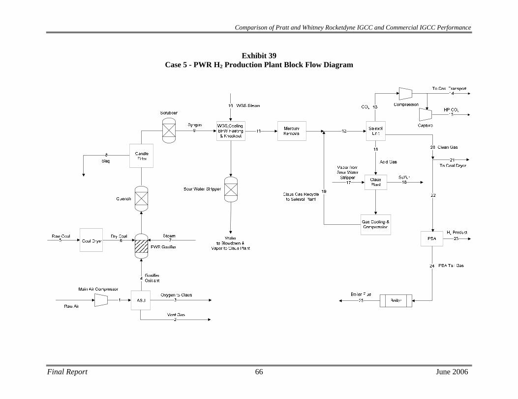
Comparison of Pratt and Whitney Rocketdyne IGCC and Commercial IGCC Performance
Exhibit 39 Case 5 - PWR H2 Production Plant Block Flow Diagram
Final Report 66 June 2006
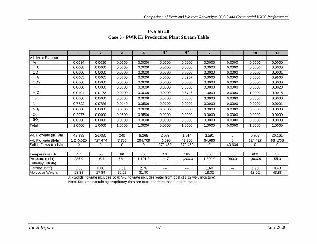
Comparison of Pratt and Whitney Rocketdyne IGCC and Commercial IGCC Performance
Exhibit 40 Case 5 - PWR H2 Production Plant Stream Table
1 2 3 4 5A 6A 7 8 10 13
V-L Mole FractionAr 0.0094 0.0036 0.0360 0.0000 0.0000 0.0000 0.0000 0.0000 0.0000 0.0000CH4 0.0000 0.0000 0.0000 0.0000 0.0000 0.0000 0.0000 0.0000 0.0000 0.0000CO 0.0000 0.0000 0.0000 0.0000 0.0000 0.0000 0.0000 0.0000 0.0000 0.0001CO2 0.0003 0.0005 0.0000 0.0000 0.0000 0.3257 0.0000 0.0000 0.0000 0.9963COS 0.0000 0.0000 0.0000 0.0000 0.0000 0.0000 0.0000 0.0000 0.0000 0.0000H2 0.0000 0.0000 0.0000 0.0000 0.0000 0.0000 0.0000 0.0000 0.0000 0.0020H2O 0.0104 0.0172 0.0000 0.0000 0.0000 0.6743 1.0000 0.0000 1.0000 0.0015H2S 0.0000 0.0000 0.0000 0.0000 0.0000 0.0000 0.0000 0.0000 0.0000 0.0000N2 0.7722 0.9786 0.0140 0.0500 0.0000 0.0000 0.0000 0.0000 0.0000 0.0001NH3 0.0000 0.0000 0.0000 0.0000 0.0000 0.0000 0.0000 0.0000 0.0000 0.0000O2 0.2077 0.0000 0.9500 0.9500 0.0000 0.0000 0.0000 0.0000 0.0000 0.0000SO2 0.0000 0.0000 0.0000 0.0000 0.0000 0.0000 0.0000 0.0000 0.0000 0.0000
Total 1.0000 1.0000 1.0000 1.0000 0.0000 1.0000 1.0000 0.0000 1.0000 1.0000
V-L Flowrate (lbmol/hr) 42,993 26,080 240 9,268 2,589 1,614 3,591 0 6,907 20,161V-L Flowrate (lb/hr) 1,240,520 727,474 7,730 294,709 46,598 42,706 64,696 0 124,427 884,738Solids Flowrate (lb/hr) 0 0 0 0 372,452 372,452 0 40,634 0 0
Temperature (°F) 271 55 90 800 59 195 800 500 600 58Pressure (psia) 225.0 16.4 56.4 1,191.2 14.7 1,200.0 1,200.0 990.0 1,000.0 55.0Enthalpy (Btu/lb)Density (lb/ft3) 0.83 0.08 0.31 2.76 --- --- 1.60 --- 1.93 0.43Molecular Weight 28.85 27.89 32.23 31.80 --- --- 18.02 --- 18.02 43.88
A - Solids flowrate includes coal; V-L flowrate includes water from coal (11.12 wt% moisture)Note: Streams containing proprietary data are excluded from these stream tables
Final Report 67 June 2006
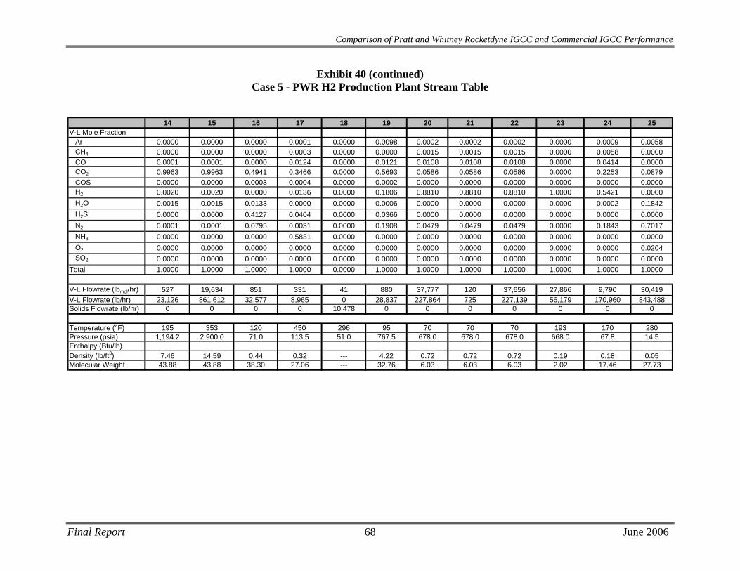
Final Report 68 June 2006
14 15 16 17 18 19 20 21 22 23 24 25
V-L Mole FractionAr 0.0000 0.0000 0.0000 0.0001 0.0000 0.0098 0.0002 0.0002 0.0002 0.0000 0.0009 0.0058CH4 0.0000 0.0000 0.0000 0.0003 0.0000 0.0000 0.0015 0.0015 0.0015 0.0000 0.0058 0.0000CO 0.0001 0.0001 0.0000 0.0124 0.0000 0.0121 0.0108 0.0108 0.0108 0.0000 0.0414 0.0000CO2 0.9963 0.9963 0.4941 0.3466 0.0000 0.5693 0.0586 0.0586 0.0586 0.0000 0.2253 0.0879COS 0.0000 0.0000 0.0003 0.0004 0.0000 0.0002 0.0000 0.0000 0.0000 0.0000 0.0000 0.0000H2 0.0020 0.0020 0.0000 0.0136 0.0000 0.1806 0.8810 0.8810 0.8810 1.0000 0.5421 0.0000H2O 0.0015 0.0015 0.0133 0.0000 0.0000 0.0006 0.0000 0.0000 0.0000 0.0000 0.0002 0.1842H2S 0.0000 0.0000 0.4127 0.0404 0.0000 0.0366 0.0000 0.0000 0.0000 0.0000 0.0000 0.0000N2 0.0001 0.0001 0.0795 0.0031 0.0000 0.1908 0.0479 0.0479 0.0479 0.0000 0.1843 0.7017NH3 0.0000 0.0000 0.0000 0.5831 0.0000 0.0000 0.0000 0.0000 0.0000 0.0000 0.0000 0.0000O2 0.0000 0.0000 0.0000 0.0000 0.0000 0.0000 0.0000 0.0000 0.0000 0.0000 0.0000 0.0204SO2 0.0000 0.0000 0.0000 0.0000 0.0000 0.0000 0.0000 0.0000 0.0000 0.0000 0.0000 0.0000
Total 1.0000 1.0000 1.0000 1.0000 0.0000 1.0000 1.0000 1.0000 1.0000 1.0000 1.0000 1.0000
V-L Flowrate (lbmol/hr) 527 19,634 851 331 41 880 37,777 120 37,656 27,866 9,790 30,419V-L Flowrate (lb/hr) 23,126 861,612 32,577 8,965 0 28,837 227,864 725 227,139 56,179 170,960 843,488Solids Flowrate (lb/hr) 0 0 0 0 10,478 0 0 0 0 0 0 0
Temperature (°F) 195 353 120 450 296 95 70 70 70 193 170 280Pressure (psia) 1,194.2 2,900.0 71.0 113.5 51.0 767.5 678.0 678.0 678.0 668.0 67.8 14.5Enthalpy (Btu/lb)Density (lb/ft3) 7.46 14.59 0.44 0.32 --- 4.22 0.72 0.72 0.72 0.19 0.18 0.05Molecular Weight 43.88 43.88 38.30 27.06 --- 32.76 6.03 6.03 6.03 2.02 17.46 27.73
Comparison of Pratt and Whitney Rocketdyne IGCC and Commercial IGCC Performance
Exhibit 40 (continued) Case 5 - PWR H2 Production Plant Stream Table
Comparison of Pratt and Whitney Rocketdyne IGCC and Commercial IGCC Performance
6.3 Equipment Descriptions
Coal Preparation and Feed Systems The coal as received contains 11.12 percent moisture, and must be dried to 5 percent or less moisture. The coal is simultaneously crushed and dried using an air-fed combustion of clean synthesis gas from the exit of the Selexol unit. Crushed and dried coal is delivered to a surge hopper with an approximate 2-hour capacity.
The coal is drawn from the surge hoppers and fed through a developmental proprietary dry coal feed pump system, which uses CO2 to convey the coal to the gasifiers.
Air Separation Unit The air separation plant is designed to produce a nominal output of 3,600 tons/day of 95 percent pure O2 from two ASU production trains. Most of the oxygen is used in the gasifier. A small portion, approximately 92 tons/day, is used in the Claus plant. The air compressor is powered by an electric motor.
Gasifier The PWR gasifier uses a plug-flow entrained reactor and a multi-port injection nozzle to increase the kinetics and conversion of the gasification reaction. The PWR gasification process gasifies dried coal with steam and 95% (by volume) oxygen at ~2500°F and 1,000 psia. The PWR process claims a 100% carbon conversion and faster kinetics allowing for a more compact gasifier design. The prototype reactor designed to process 3,000 tons of dried coal per day is anticipated to be 39 inches in diameter and 15 feet in length. The amount of dried coal processed in this study is approximately 5,000 tons per day.
Syngas Cooling
Hot syngas and molten solids from the reactor flow downward through a quench region where the syngas is cooled to ~500°F. The gas and solidified slag then flow through a cyclone and candle filter system for dry particulate removal, from which the recovered solids are let down to ambient pressure.
Syngas Scrubbing The syngas enters the syngas scrubber and is directed downwards by a dip tube into a water sump at the bottom of the syngas scrubber. Most of the solids are separated from the syngas at the bottom of the dip tube as the syngas goes upwards through the water. From the overhead of the syngas scrubber, the syngas enters the low-temperature gas cooling section for further cooling.
The water removed from the syngas scrubber contains all the solids that were not removed in the quench gasifier water sump. In order to limit the amount of solids recycled to the quench chamber, a continuous blowdown stream is removed from the bottom of the syngas scrubber. The blowdown is sent to the vacuum flash drum in the black water flash section. The circulating scrubbing water is pumped by the syngas scrubber circulating pumps to the quench gasifier.
Final Report 69 June 2006
Comparison of Pratt and Whitney Rocketdyne IGCC and Commercial IGCC Performance
The slag handling system removes solids from the gasification process equipment. These solids consist of a small amount of unconverted carbon and essentially all of the ash contained in the feed coal. These solids are in the form of glass, which is non-leaching and fully encapsulates any metals.
Water Gas Shift Reaction The saturated syngas enters the WGS system fully saturated at 446°F. The raw-gas shift to produce H2 requires 124,427 lb/hr of steam, fulfilling a vendor-specified steam to dry gas molar ratio of 1.1. Steam at 600°F and 1,000 psia is added to the syngas, bringing the stream temperature to ~460°F as it enters the WGS reactors. The water gas shift reaction is as follows:
CO + H2O H2 + CO2
There are a total of three WGS reactors containing proprietary sulfur-tolerant catalyst. Each of these reactor stages is intercooled, bringing the stream temperature down to 450°F before entering the next WGS reactor. The WGS reaction is exothermic and increases the temperature of the syngas stream, though conversion is favored at lower temperatures. Lowering the temperature to 450°F before each stage results in a 98.6% overall conversion of CO.
The WGS reactors also hydrolyzes COS and converts HCN to NH3, therefore, no dedicated COS hydrolysis reactor is required.
Low Temperature Gas Cooling
Before the raw fuel gas can be treated in the AGR process, it must be cooled to about 100°F. During this cooling through a series of heat exchangers, part of the water vapor condenses. This water, which contains some NH3, is sent to the wastewater treatment section.
Mercury Removal
Refer to Case 1 in section 2.3 for a description of the Mercury Removal system used in Case 5, since they are similar.
Acid Gas/CO2 Removal
Case 5 utilizes a multi-stage Selexol process to remove sulfur with ~90% CO2 capture. The Selexol process treats the stream of synthesis gas to reduce the level of total sulfur (H2S and COS) to no more than 30 ppm prior to it being sent to the PSA, while concentrating the CO2 for compression and capture. A recycle stream of acid gas from the sulfur recovery unit (SRU) is also treated. An acid gas stream that contains ~50 percent sulfur is produced.
High sulfur, shifted gas is sent to the first absorber, which is labeled the H2S absorber. Here it contacts a “CO2-loaded” solvent, which enters at the top of the tower. In the H2S absorber, H2S, COS, CO2, and other gases such as hydrogen, are transferred from the gas phase to the liquid phase. The treated gas exits the absorber and is sent to the CO2 absorber where the gas first contacts a “semi-lean” solvent in the middle stages of the absorber. In these stages of the CO2 absorber, the large majority of the CO2 is transferred from the gas phase to the liquid phase. Fully regenerated, lean solvent enters the upper stages of this CO2 absorber, removing additional CO2 from the gas stream. The gas then leaves the CO2 absorber for treatment in the Pressure Swing Adsorption system to concentrate the H2. The solvent from the CO2 absorber is split and
Final Report 70 June 2006
Comparison of Pratt and Whitney Rocketdyne IGCC and Commercial IGCC Performance
a portion is sent to the H2S absorber as the “CO2-loaded” solvent. The remaining portion of the solvent is passed through a series of flash drums which transfer the absorbed CO2 from the liquid phase into the gas phase for compression. The remaining solvent is sent to the mid-stages of the CO2 absorber as the “semi-lean” solvent to absorb the majority of gas phase CO2.
The solvent stream from the H2S absorber is termed rich solvent and is sent to the H2S concentrator, where portions of the CO2, CO, H2, and other gases are stripped from the solvent. Nitrogen from the ASU is used as the stripping medium. A portion of the overhead gas is recycled back to the H2S absorber for further treatment. The partially regenerated solvent exits the H2S concentrator and is sent to the stripper, where the solvent is fully regenerated. All gases are transferred from the liquid phase to the gas phase in this stripper and sent to the Sulfur Recovery System (SRS). The Tail gas from the SRS is recycled back to the AGR unit and enters with the feed to the H2S absorber.
Sour Water Stripper Refer to Case 1 in section 2.3 for a description of the Sour Water Stripper used in Case 5, since they are similar.
Sulfur Recovery System The sulfur recovery unit is a Claus bypass-type sulfur recovery unit utilizing oxygen instead of air. The Claus plant produces molten sulfur by reacting approximately a third of the H2S in the feed to SO2, then reacting the H2S and SO2 to sulfur and water. Utilizing oxygen instead of air in the Claus plant reduces the overall cost of the sulfur recovery plant. The sulfur plant will produce approximately 113 long tons of elemental sulfur per day. Feed for this case consists of acid gas from both acid gas cleanup units and a vent stream from the sour water stream in the gasifier section. Tail gas from the Claus unit, after hydrogenation, is recycled to the Selexol unit. The combination of Claus technology and tail gas recycle will result in an overall sulfur recovery exceeding 99 percent.
Pressure Swing Adsorption System The H2-rich gas from the Selexol unit enters multiple, parallel beds of proprietary adsorbent. These beds are used in a semi-batch adsorption/desorption sequence for continuous H2 production. The H2-rich stream is fed at high pressure (~680 psia) to force contaminant adsorption onto the beds. The H2 does not adsorb as strongly as the contaminant compounds, thus, can exit the beds at concentrations in excess of 99.99% before the beds become saturated.
Desorption occurs by depressurizing the beds to ~70 psia and back-flushing them with H2 product. This low pressure flush purges the contaminants consisting of CO, CO2, N2, and CH4 from the bed in a stream of ~50% H2. Overall H2 recovery for the PSA system is 84%; however, the overall H2 recovery of the plant is slightly less than 84% due to the fuel requirement for coal drying.
Boiler Off-gas from the PSA unit is combusted with excess air in a waste heat boiler to provide heat for steam generation. A conventional natural gas-fired boiler must be retrofitted with syngas burners to provide stable combustion with low NOx generation.
Final Report 71 June 2006
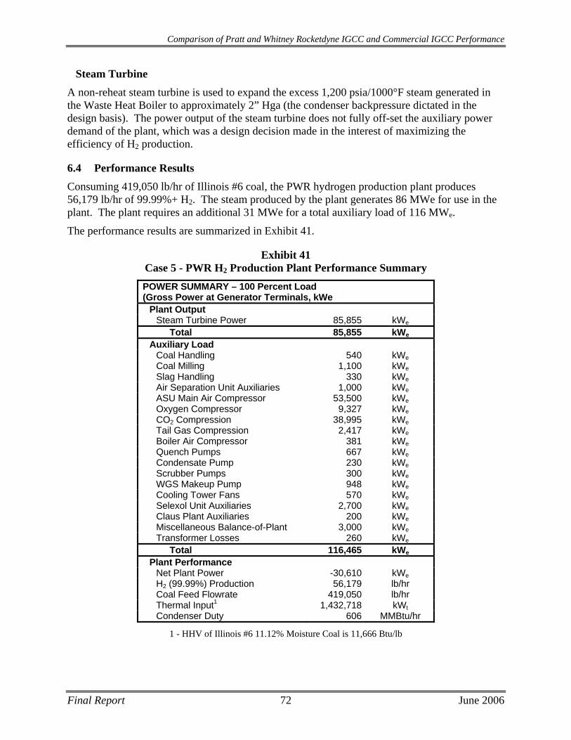
Comparison of Pratt and Whitney Rocketdyne IGCC and Commercial IGCC Performance
Steam Turbine
A non-reheat steam turbine is used to expand the excess 1,200 psia/1000°F steam generated in the Waste Heat Boiler to approximately 2” Hga (the condenser backpressure dictated in the design basis). The power output of the steam turbine does not fully off-set the auxiliary power demand of the plant, which was a design decision made in the interest of maximizing the efficiency of H2 production.
6.4 Performance Results Consuming 419,050 lb/hr of Illinois #6 coal, the PWR hydrogen production plant produces 56,179 lb/hr of 99.99%+ H2. The steam produced by the plant generates 86 MWe for use in the plant. The plant requires an additional 31 MWe for a total auxiliary load of 116 MWe.
The performance results are summarized in Exhibit 41.
Exhibit 41 Case 5 - PWR H2 Production Plant Performance Summary POWER SUMMARY – 100 Percent Load (Gross Power at Generator Terminals, kWe
Plant Output Steam Turbine Power 85,855 kWe
Total 85,855 kWe
Auxiliary Load Coal Handling 540 kWeCoal Milling 1,100 kWeSlag Handling 330 kWeAir Separation Unit Auxiliaries 1,000 kWeASU Main Air Compressor 53,500 kWeOxygen Compressor 9,327 kWeCO2 Compression 38,995 kWeTail Gas Compression 2,417 kWeBoiler Air Compressor 381 kWeQuench Pumps 667 kWeCondensate Pump 230 kWeScrubber Pumps 300 kWeWGS Makeup Pump 948 kWeCooling Tower Fans 570 kWeSelexol Unit Auxiliaries 2,700 kWeClaus Plant Auxiliaries 200 kWeMiscellaneous Balance-of-Plant 3,000 kWeTransformer Losses 260 kWe
Total 116,465 kWe
Plant Performance Net Plant Power -30,610 kWeH2 (99.99%) Production 56,179 lb/hr Coal Feed Flowrate 419,050 lb/hr Thermal Input1 1,432,718 kWtCondenser Duty 606 MMBtu/hr
1 - HHV of Illinois #6 11.12% Moisture Coal is 11,666 Btu/lb
Final Report 72 June 2006
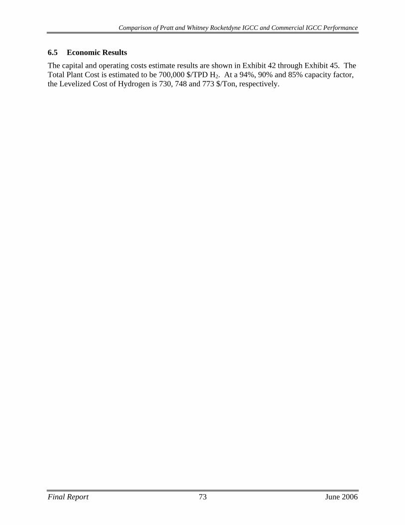
Comparison of Pratt and Whitney Rocketdyne IGCC and Commercial IGCC Performance
Final Report 73 June 2006
6.5 Economic Results
The capital and operating costs estimate results are shown in Exhibit 42 through Exhibit 45. The Total Plant Cost is estimated to be 700,000 $/TPD H2. At a 94%, 90% and 85% capacity factor, the Levelized Cost of Hydrogen is 730, 748 and 773 $/Ton, respectively.
Final Report 74 June 2006
Comparison of Pratt and Whitney Rocketdyne IGCC and Commercial IGCC Performance
Exhibit 42 Case 5 - PWR H2 Production Total Plant Capital Costs
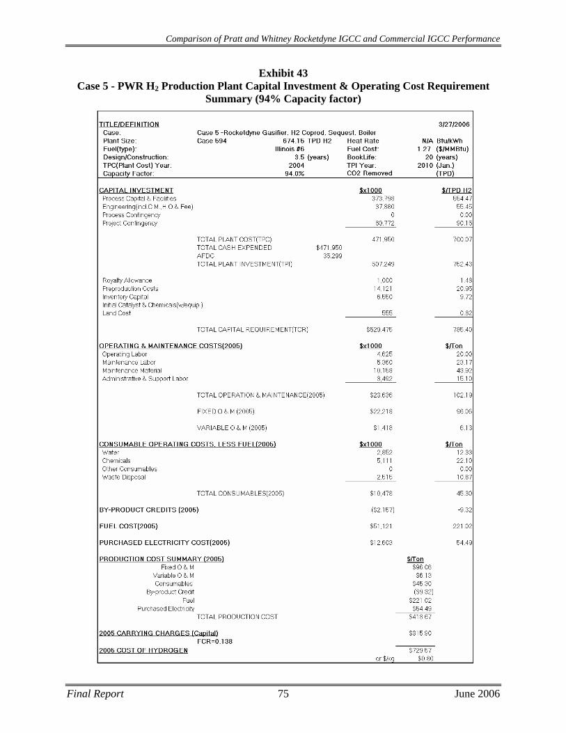
Comparison of Pratt and Whitney Rocketdyne IGCC and Commercial IGCC Performance
Exhibit 43 Case 5 - PWR H2 Production Plant Capital Investment & Operating Cost Requirement
Summary (94% Capacity factor)
Final Report 75 June 2006
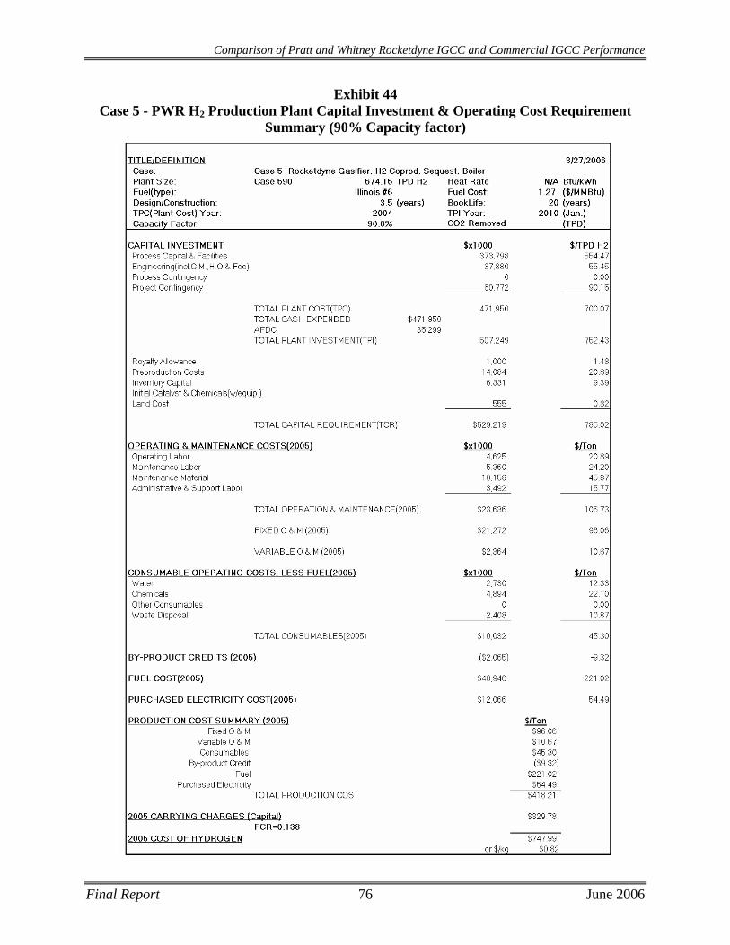
Comparison of Pratt and Whitney Rocketdyne IGCC and Commercial IGCC Performance
Exhibit 44 Case 5 - PWR H2 Production Plant Capital Investment & Operating Cost Requirement
Summary (90% Capacity factor)
Final Report 76 June 2006

Comparison of Pratt and Whitney Rocketdyne IGCC and Commercial IGCC Performance
Exhibit 45 Case 5 - PWR H2 Production Plant Capital Investment & Operating Cost Requirement
Summary (85% Capacity factor)
Final Report 77 June 2006

Comparison of Pratt and Whitney Rocketdyne IGCC and Commercial IGCC Performance
This page intentionally left blank
Final Report 78 June 2006
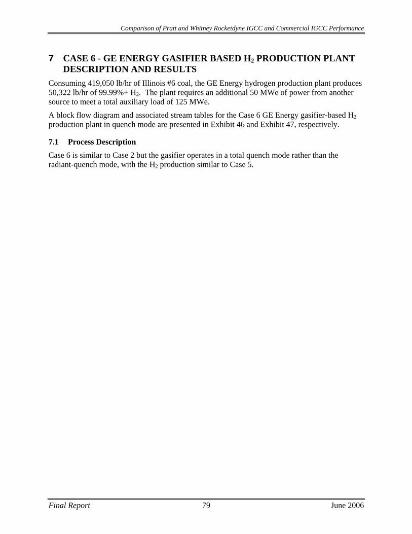
Comparison of Pratt and Whitney Rocketdyne IGCC and Commercial IGCC Performance
Final Report 79 June 2006
7 CASE 6 - GE ENERGY GASIFIER BASED H2 PRODUCTION PLANT DESCRIPTION AND RESULTS
Consuming 419,050 lb/hr of Illinois #6 coal, the GE Energy hydrogen production plant produces 50,322 lb/hr of 99.99%+ H2. The plant requires an additional 50 MWe of power from another source to meet a total auxiliary load of 125 MWe.
A block flow diagram and associated stream tables for the Case 6 GE Energy gasifier-based H2 production plant in quench mode are presented in Exhibit 46 and Exhibit 47, respectively.
7.1 Process Description Case 6 is similar to Case 2 but the gasifier operates in a total quench mode rather than the radiant-quench mode, with the H2 production similar to Case 5.
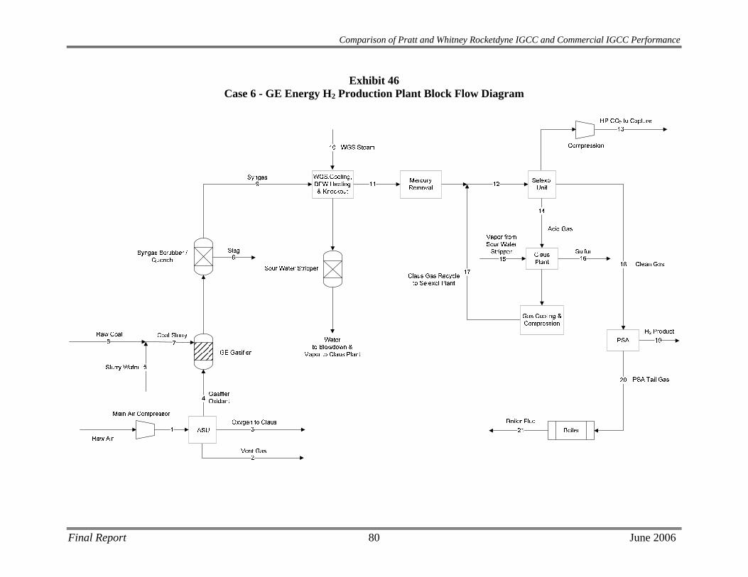
Comparison of Pratt and Whitney Rocketdyne IGCC and Commercial IGCC Performance
Exhibit 46 Case 6 - GE Energy H2 Production Plant Block Flow Diagram
Final Report 80 June 2006
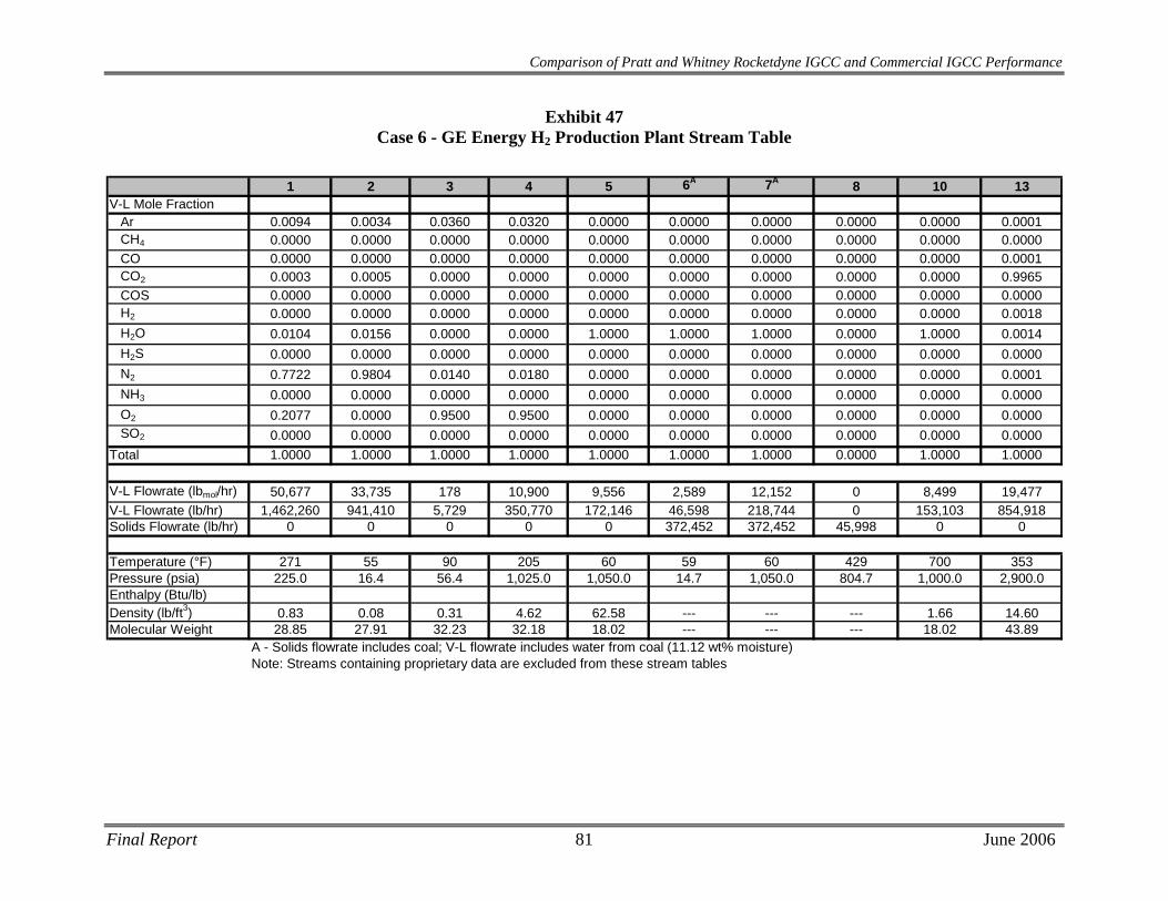
Comparison of Pratt and Whitney Rocketdyne IGCC and Commercial IGCC Performance
Exhibit 47 Case 6 - GE Energy H2 Production Plant Stream Table
1 2 3 4 5 6A 7A 8 10 13
V-L Mole FractionAr 0.0094 0.0034 0.0360 0.0320 0.0000 0.0000 0.0000 0.0000 0.0000 0.0001CH4 0.0000 0.0000 0.0000 0.0000 0.0000 0.0000 0.0000 0.0000 0.0000 0.0000CO 0.0000 0.0000 0.0000 0.0000 0.0000 0.0000 0.0000 0.0000 0.0000 0.0001CO2 0.0003 0.0005 0.0000 0.0000 0.0000 0.0000 0.0000 0.0000 0.0000 0.9965COS 0.0000 0.0000 0.0000 0.0000 0.0000 0.0000 0.0000 0.0000 0.0000 0.0000H2 0.0000 0.0000 0.0000 0.0000 0.0000 0.0000 0.0000 0.0000 0.0000 0.0018H2O 0.0104 0.0156 0.0000 0.0000 1.0000 1.0000 1.0000 0.0000 1.0000 0.0014H2S 0.0000 0.0000 0.0000 0.0000 0.0000 0.0000 0.0000 0.0000 0.0000 0.0000N2 0.7722 0.9804 0.0140 0.0180 0.0000 0.0000 0.0000 0.0000 0.0000 0.0001NH3 0.0000 0.0000 0.0000 0.0000 0.0000 0.0000 0.0000 0.0000 0.0000 0.0000O2 0.2077 0.0000 0.9500 0.9500 0.0000 0.0000 0.0000 0.0000 0.0000 0.0000SO2 0.0000 0.0000 0.0000 0.0000 0.0000 0.0000 0.0000 0.0000 0.0000 0.0000
Total 1.0000 1.0000 1.0000 1.0000 1.0000 1.0000 1.0000 0.0000 1.0000 1.0000
V-L Flowrate (lbmol/hr) 50,677 33,735 178 10,900 9,556 2,589 12,152 0 8,499 19,477V-L Flowrate (lb/hr) 1,462,260 941,410 5,729 350,770 172,146 46,598 218,744 0 153,103 854,918Solids Flowrate (lb/hr) 0 0 0 0 0 372,452 372,452 45,998 0 0
Temperature (°F) 271 55 90 205 60 59 60 429 700 353Pressure (psia) 225.0 16.4 56.4 1,025.0 1,050.0 14.7 1,050.0 804.7 1,000.0 2,900.0Enthalpy (Btu/lb)Density (lb/ft3) 0.83 0.08 0.31 4.62 62.58 --- --- --- 1.66 14.60Molecular Weight 28.85 27.91 32.23 32.18 18.02 --- --- --- 18.02 43.89
A - Solids flowrate includes coal; V-L flowrate includes water from coal (11.12 wt% moisture)Note: Streams containing proprietary data are excluded from these stream tables
Final Report 81 June 2006
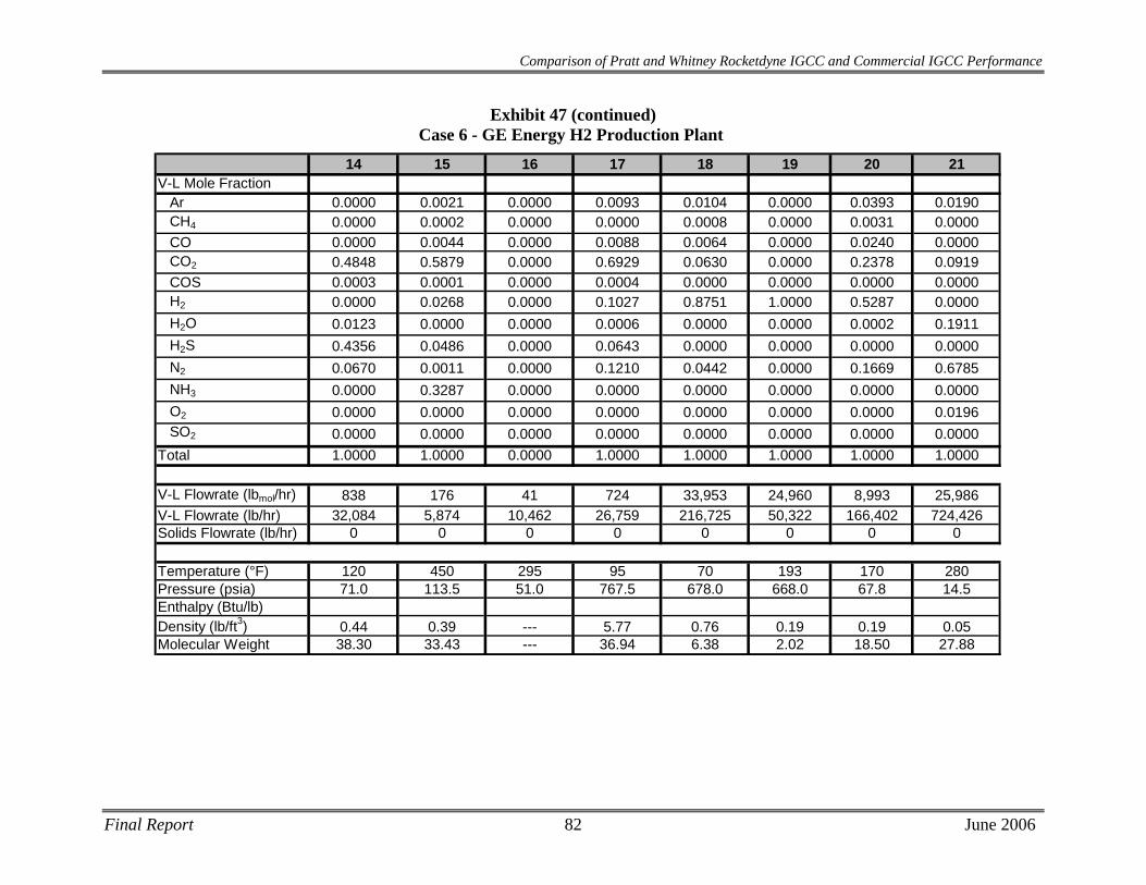
Final Report 82 June 2006
Comparison of Pratt and Whitney Rocketdyne IGCC and Commercial IGCC Performance
14 15 16 17 18 19 20 21V-L Mole Fraction
Ar 0.0000 0.0021 0.0000 0.0093 0.0104 0.0000 0.0393 0.0190CH4 0.0000 0.0002 0.0000 0.0000 0.0008 0.0000 0.0031 0.0000CO 0.0000 0.0044 0.0000 0.0088 0.0064 0.0000 0.0240 0.0000CO2 0.4848 0.5879 0.0000 0.6929 0.0630 0.0000 0.2378 0.0919COS 0.0003 0.0001 0.0000 0.0004 0.0000 0.0000 0.0000 0.0000H2 0.0000 0.0268 0.0000 0.1027 0.8751 1.0000 0.5287 0.0000H2O 0.0123 0.0000 0.0000 0.0006 0.0000 0.0000 0.0002 0.1911H2S 0.4356 0.0486 0.0000 0.0643 0.0000 0.0000 0.0000 0.0000N2 0.0670 0.0011 0.0000 0.1210 0.0442 0.0000 0.1669 0.6785NH3 0.0000 0.3287 0.0000 0.0000 0.0000 0.0000 0.0000 0.0000O2 0.0000 0.0000 0.0000 0.0000 0.0000 0.0000 0.0000 0.0196SO2 0.0000 0.0000 0.0000 0.0000 0.0000 0.0000 0.0000 0.0000
Total 1.0000 1.0000 0.0000 1.0000 1.0000 1.0000 1.0000 1.0000
V-L Flowrate (lbmol/hr) 838 176 41 724 33,953 24,960 8,993 25,986V-L Flowrate (lb/hr) 32,084 5,874 10,462 26,759 216,725 50,322 166,402 724,426Solids Flowrate (lb/hr) 0 0 0 0 0 0 0 0
Temperature (°F) 120 450 295 95 70 193 170 280Pressure (psia) 71.0 113.5 51.0 767.5 678.0 668.0 67.8 14.5Enthalpy (Btu/lb)Density (lb/ft3) 0.44 0.39 --- 5.77 0.76 0.19 0.19 0.05Molecular Weight 38.30 33.43 --- 36.94 6.38 2.02 18.50 27.88
Exhibit 47 (continued) Case 6 - GE Energy H2 Production Plant
Comparison of Pratt and Whitney Rocketdyne IGCC and Commercial IGCC Performance
7.2 Equipment Descriptions
Air Separation Unit The air separation plant is designed to produce a nominal output of 4,300 tons/day of 95 percent pure O2 from two ASU production trains. Most of the oxygen is used in the gasifier. A small portion, approximately 70 tons/day, is used in the Claus plant. The air compressor is powered by an electric motor.
Gasifier This plant utilizes two gasification trains to process a total of 5,000 tons per day of coal. The slurry feed pump takes suction from the slurry run tank, and the discharge is sent to the feed injector of the GEE gasifier. Oxygen from the ASU is vented during preparation for startup and is sent to the feed injector during normal operation. The air separation plant supplies 2,100 tons of 95 percent purity oxygen per day to each gasifier.
The gasifier vessel is a refractory-lined, high-pressure combustion chamber. Coal slurry is transferred from the slurry storage tank to the gasifier with a high-pressure pump. At the top of the gasifier vessel is located a combination fuel injector through which coal slurry feedstock and oxidant (oxygen) are fed. The coal slurry and the oxygen feeds react in the gasifier at about 815 psia at a high temperature (in excess of 2,400°F) to produce syngas.
The syngas consists primarily of hydrogen and carbon monoxide, with lesser amounts of water vapor and carbon dioxide, and small amounts of hydrogen sulfide, carbonyl sulfide, methane, argon, and nitrogen. The heat in the gasifier liquefies coal ash.
Syngas Cooling Hot syngas and molten solids from the reactor flow downward through a quench region where the syngas is cooled to ~430°F. The gas and solidified slag then flow into a water-filled quench chamber. The solids collect in the water sump at the bottom of the gasifier and are removed periodically, using a lock hopper system.
Solids collected in the quench gasifier water sump are removed by gravity and forced circulation of water from the lock hopper circulating pump. Fine material, which does not settle as easily, is removed in the gasification blowdown which is sent to the vacuum flash drum by way of the syngas scrubber.
Syngas Scrubbing The syngas enters the syngas scrubber and is directed downwards by a dip tube into a water sump at the bottom of the syngas scrubber. Most of the solids are separated from the syngas at the bottom of the dip tube as the syngas goes upwards through the water. From the overhead of the syngas scrubber, the syngas enters the low-temperature gas cooling section for further cooling.
The water removed from the syngas scrubber contains all the solids that were not removed in the quench gasifier water sump. In order to limit the amount of solids recycled to the quench chamber, a continuous blowdown stream is removed from the bottom of the syngas scrubber.
Final Report 83 June 2006
Comparison of Pratt and Whitney Rocketdyne IGCC and Commercial IGCC Performance
The blowdown is sent to the vacuum flash drum in the black water flash section. The circulating scrubbing water is pumped by the syngas scrubber circulating pumps to the quench gasifier.
The slag handling system removes solids from the gasification process equipment. These solids consist of a small amount of unconverted carbon and essentially all of the ash contained in the feed coal. These solids are in the form of glass, which is non-leaching and fully encapsulates any metals.
Water Gas Shift (WGS) Reactors The saturated syngas enters the WGS system fully saturated at ~430°F. The raw-gas shift to produce H2 requires 153,103 lb/hr of steam, fulfilling a vendor-specified steam to dry gas ratio of 1.1. Steam at 700°F and 1,000 psia is added to the syngas, bringing the stream temperature to ~460°F as it enters the WGS reactors. The water gas shift reaction is as follows:
CO + H2O H2 + CO2
There are a total of three WGS reactors containing proprietary sulfur-tolerant catalyst. Each of these reactor stages is intercooled, bringing the stream temperature down to 450°F before entering the next WGS reactor. The WGS reaction is exothermic and increases the temperature of the syngas stream, though conversion is favored at lower temperatures. Lowering the temperature to 450°F before each stage results in a 98.6% overall conversion of CO.
The WGS reactors also hydrolyzes COS and converts HCN to NH3, therefore, no dedicated COS hydrolysis reactor is required.
Low Temperature Gas Cooling
Before the raw fuel gas can be treated in the AGR process, it must be cooled to about 100°F. During this cooling through a series of heat exchangers, part of the water vapor condenses. This water, which contains some NH3, is sent to the wastewater treatment section.
Mercury Removal
Refer to Case 1 in section 2.3 for a description of the Mercury Removal system used in Case 6, since they are similar.
Acid Gas/CO2 Removal
Case 6 utilizes a multi-stage Selexol process to remove sulfur with ~90% CO2 capture. The Selexol process treats the stream of synthesis gas to reduce the level of total sulfur (H2S and COS) to no more than 30 ppm prior to it being sent to the PSA, while concentrating the CO2 for compression and capture. A recycle stream of acid gas from the sulfur recovery unit (SRU) is also treated. An acid gas stream that contains ~50 percent sulfur is produced.
High sulfur, shifted gas is sent to the first absorber, which is labeled the H2S absorber. Here it contacts a “CO2-loaded” solvent, which enters at the top of the tower. In the H2S absorber, H2S, COS, CO2, and other gases such as hydrogen, are transferred from the gas phase to the liquid phase. The treated gas exits the absorber and is sent to the CO2 absorber where the gas first contacts a “semi-lean” solvent in the middle stages of the absorber. In these stages of the CO2 absorber, the large majority of the CO2 is transferred from the gas phase to the liquid phase. Fully regenerated, lean solvent enters the upper stages of this CO2 absorber, removing additional
Final Report 84 June 2006

Comparison of Pratt and Whitney Rocketdyne IGCC and Commercial IGCC Performance
CO2 from the gas stream. The gas then leaves the CO2 absorber for treatment in the Pressure Swing Adsorption system to concentrate the H2. The solvent from the CO2 absorber is split and a portion is sent to the H2S absorber as the “CO2-loaded” solvent. The remaining portion of the solvent is passed through a series of flash drums which transfer the absorbed CO2 from the liquid phase into the gas phase for compression. The remaining solvent is sent to the mid-stages of the CO2 absorber as the “semi-lean” solvent to absorb the majority of gas phase CO2.
The solvent stream from the H2S absorber is termed rich solvent and is sent to the H2S concentrator, where portions of the CO2, CO, H2, and other gases are stripped from the solvent. Nitrogen from the ASU is used as the stripping medium. A portion of the overhead gas is recycled back to the H2S absorber for further treatment. The partially regenerated solvent exits the H2S concentrator and is sent to the stripper, where the solvent is fully regenerated. All gases are transferred from the liquid phase to the gas phase in this stripper and sent to the Sulfur Recovery System (SRS). The Tail gas from the SRS is recycled back to the AGR unit and enters with the feed to the H2S absorber.
Sour Water Stripper Refer to Case 1 in section 2.3 for a description of the Sour Water Stripper used in Case 6, since they are similar.
Sulfur Recovery System The sulfur recovery unit is a Claus bypass-type sulfur recovery unit utilizing oxygen instead of air. The Claus plant produces molten sulfur by reacting approximately a third of the H2S in the feed to SO2, then reacting the H2S and SO2 to sulfur and water. Utilizing oxygen instead of air in the Claus plant reduces the overall cost of the sulfur recovery plant. The sulfur plant will produce approximately 113 long tons of elemental sulfur per day. Feed for this case consists of acid gas from both acid gas cleanup units and a vent stream from the sour water stream in the gasifier section. Tail gas from the Claus unit, after hydrogenation, is recycled to the Selexol unit. The combination of Claus technology and tail gas recycle will result in an overall sulfur recovery exceeding 99 percent.
Pressure Swing Adsorption System The H2-rich gas from the Selexol unit enters multiple, parallel beds of proprietary adsorbent. These beds are used in a semi-batch adsorption/desorption sequence for continuous H2 production. The H2-rich stream is fed at high pressure (~680 PSI) to force contaminant adsorption onto the beds. The H2 does not adsorb as strongly as the contaminant compounds, thus, can exit the beds at concentrations in excess of 99.99% before the beds become saturated.
Desorption occurs by depressurizing the beds to ~70 PSI and back-flushing them with H2 product. This low pressure flush purges the contaminants consisting of CO, CO2, N2, and CH4 from the bed in a stream of ~50% H2. Overall H2 recovery for the PSA system is designed to be 84%.
Final Report 85 June 2006
Comparison of Pratt and Whitney Rocketdyne IGCC and Commercial IGCC Performance
Waste Heat Boiler
Off-gas from the PSA unit is combusted with excess air in a waste heat boiler to provide heat for steam generation. A conventional natural gas-fired boiler must be retrofitted with syngas burners to provide stable combustion with low NOx generation.
Steam Turbine A non-reheat steam turbine is used to expand the excess 1,200 psia/1000°F steam generated in the Waste Heat Boiler to approximately 2” Hga (the condenser backpressure dictated in the design basis). The power output of the steam turbine does not fully off-set the auxiliary power demand of the plant, which was a design decision made in the interest of maximizing the efficiency of H2 production.
7.3 Performance Results
Utilizing 419,050 lb/hr of Illinois #6 coal, the GE gasifier hydrogen plant produces 50,322 lb/hr of 99.99%+ H2. The steam produced by the plant generates 75 MWe for internal use. The plant requires an additional 50 MWe to meet a total auxiliary load of 125MWe.
The performance results are summarized in Exhibit 48.
Final Report 86 June 2006
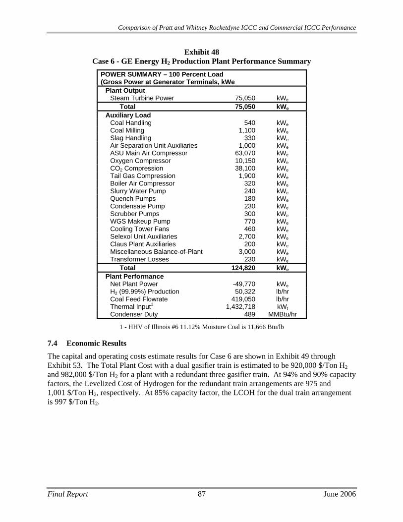
Comparison of Pratt and Whitney Rocketdyne IGCC and Commercial IGCC Performance
Final Report 87 June 2006
Exhibit 48 Case 6 - GE Energy H2 Production Plant Performance Summary
POWER SUMMARY – 100 Percent Load (Gross Power at Generator Terminals, kWe
Plant Output Steam Turbine Power 75,050 kWe
Total 75,050 kWe
Auxiliary Load Coal Handling 540 kWeCoal Milling 1,100 kWeSlag Handling 330 kWeAir Separation Unit Auxiliaries 1,000 kWeASU Main Air Compressor 63,070 kWeOxygen Compressor 10,150 kWeCO2 Compression 38,100 kWeTail Gas Compression 1,900 kWeBoiler Air Compressor 320 kWeSlurry Water Pump 240 kWeQuench Pumps 180 kWeCondensate Pump 230 kWeScrubber Pumps 300 kWeWGS Makeup Pump 770 kWeCooling Tower Fans 460 kWeSelexol Unit Auxiliaries 2,700 kWeClaus Plant Auxiliaries 200 kWeMiscellaneous Balance-of-Plant 3,000 kWeTransformer Losses 230 kWe
Total 124,820 kWe
Plant Performance Net Plant Power -49,770 kWeH2 (99.99%) Production 50,322 lb/hr Coal Feed Flowrate 419,050 lb/hr Thermal Input1 1,432,718 kWtCondenser Duty 489 MMBtu/hr
1 - HHV of Illinois #6 11.12% Moisture Coal is 11,666 Btu/lb
7.4 Economic Results The capital and operating costs estimate results for Case 6 are shown in Exhibit 49 through Exhibit 53. The Total Plant Cost with a dual gasifier train is estimated to be 920,000 $/Ton H2 and 982,000 $/Ton H2 for a plant with a redundant three gasifier train. At 94% and 90% capacity factors, the Levelized Cost of Hydrogen for the redundant train arrangements are 975 and 1,001 $/Ton H2, respectively. At 85% capacity factor, the LCOH for the dual train arrangement is 997 $/Ton H2.
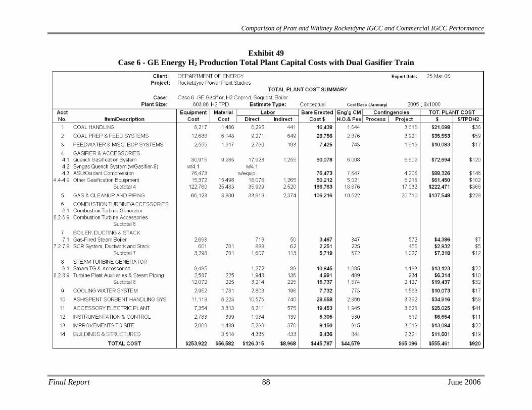
Comparison of Pratt and Whitney Rocketdyne IGCC and Commercial IGCC Performance
Exhibit 49 Case 6 - GE Energy H2 Production Total Plant Capital Costs with Dual Gasifier Train
Final Report 88 June 2006

Final Report 89 June 2006
Comparison of Pratt and Whitney Rocketdyne IGCC and Commercial IGCC Performance
Exhibit 50 Case 6 - GE Energy H2 Production Total Plant Capital Costs with Redundant Gasifier Train
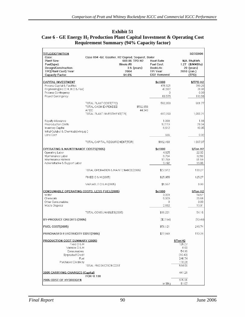
Comparison of Pratt and Whitney Rocketdyne IGCC and Commercial IGCC Performance
Exhibit 51 Case 6 - GE Energy H2 Production Plant Capital Investment & Operating Cost
Requirement Summary (94% Capacity factor)
Final Report 90 June 2006

Comparison of Pratt and Whitney Rocketdyne IGCC and Commercial IGCC Performance
Exhibit 52 Case 6 - GE Energy H2 Production Plant Capital Investment & Operating Cost
Requirement Summary (90% Capacity factor)
Final Report 91 June 2006
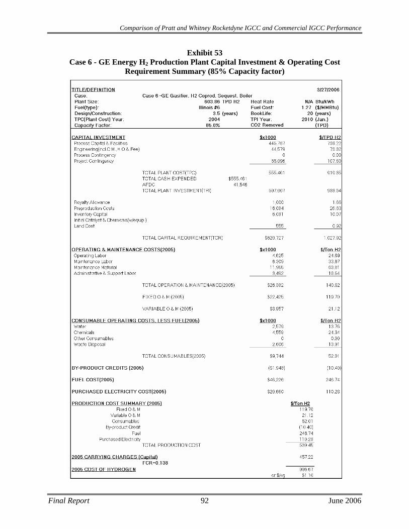
Comparison of Pratt and Whitney Rocketdyne IGCC and Commercial IGCC Performance
Exhibit 53 Case 6 - GE Energy H2 Production Plant Capital Investment & Operating Cost
Requirement Summary (85% Capacity factor)
Final Report 92 June 2006
Comparison of Pratt and Whitney Rocketdyne IGCC and Commercial IGCC Performance
8 SUMMARY This report compares six gasifier-based plant configurations. The results for each case are summarized in Exhibit 54. All results should be considered preliminary and dictated in large part by the selected design basis. It should also be noted that gasifier performance and cost data for the PWR gasifier was provided by the vendor and that RDS did not apply Process Contingency costs to the data provided. Since the design is conceptual and there has not yet been pilot plant or commercial operation, the performance and cost of the PWR gasifier should be considered preliminary.
Cases 1 and 2 reflect IGCC plants using either a PWR or a GE Energy gasifier respectively in both radiant quench heat recovery mode and similar plant configurations. Case 1 (PWR) shows a 3% net plant efficiency improvement over Case 2 (GE). In addition to the efficiency improvement, Case 1 costs more than $130 million less ($147/kWe) and shows an 8% reduction in the levelized cost of electricity on a common capacity factor. The difference is directly attributable to reduction in gasifier costs, reduction in thermal input to the plant, increased gasifier efficiency (resulting in lower oxygen requirements) and a fairly significant increase in plant availability without a spare gasifier.
Cases 3 and 4 compare PWR and Shell gasifiers in syngas quench/convective heat exchange mode. These cases exhibit more similar plant performance than PWR and GE since both gasifiers are dry coal-fed whereas the GE Energy gasifier in Case 2 is a slurry-fed gasifier (which is inherently less efficient). The net plant efficiency for the PWR gasifier plant is 0.9% higher than the comparable Shell gasification plant. In addition, there is a projected $205 million ($308/kWe) reduction in total plant cost for the PWR IGCC plant, which correlates to a 15% and 20% reduction in the levelized cost of electricity for a capacity factor of 85% and 94%, respectively. This is primarily attributable to a $94 million reduction in gasifier island costs associated with a less expensive PWR gasifier/syngas cooler arrangement but also attributable to a $66 million reduction in coal handling, preparation, and feed costs associated with using a dry coal feed pump instead of a dry coal lockhopper system. The application of a dry feed pump to the Shell gasifier can have similar cost benefits. A prior study has indicated that a capital cost reduction of about $100/kW can be taken from the feed system.[10]
Cases 5 and 6 compare the H2 production capabilities of comparably sized (by thermal input) gasification plants based on the PWR and GE Energy gasifiers, respectively. The H2 production of the Case 5 plant was 56,179 lb/hr while the Case 6 plant produced 50,322 lb/hr. This is partially attributable to the improved carbon conversion of the PWR gasifier and the fact that the PWR gasifier is dry coal-fed, both of which allow for increased availability of CO in the syngas that can be shifted in the WGS reactors, yielding increased amounts of H2 as a result. The steam turbine power output of the PWR case is greater than that of the GE Energy case due to the reduced steam demand of the PWR WGS system and due to the increased CO in the saturated syngas which generates more recoverable WGS reaction heat. Case 5 costs more than $83 million less and shows a 23% reduction in the levelized cost of hydrogen on a common capacity factor.
Final Report 93 June 2006
Comparison of Pratt and Whitney Rocketdyne IGCC and Commercial IGCC Performance
The following overall conclusions can be reached from this study:
• Based on current expectations, the PWR gasifier system presents conversion efficiencies which are significantly higher than conventional gasifiers. However, future pilot studies must be performed to verify these expectations.
• Based on inclusion of PWR-PWR estimates, the capital and operating costs of the PWR gasifier plant are significantly lower than for conventional gasifiers.
• The PWR gasifier system can offer significantly lower production costs for both power and hydrogen relative to conventional gasifier systems.
Final Report 94 June 2006

Comparison of Pratt and Whitney Rocketdyne IGCC and Commercial IGCC Performance
Exhibit 54 Performance Summary and Economic Analysis Results
Case 1 PWR
Radiant Quench
Case 2 GE Energy
Radiant Quench
Case 3 PWR
Convective
Case 4 Shell
Convective
Case 5 PWR
H2 Plant
Case 6 GE Energy
H2 Plant
Performance Gas Turbine Power, MWe 464.0 464.0 464.0 464.0 None None Sweet Gas Expander, MWe 11.8 11.9 10.9 None None None Steam Turbine Power, MWe 230.7 282.2 239.9 270.4 85.9 75.0 Gross Power Output, MWe 706.5 758.1 714.8 734.4 85.9 75.0 Auxiliary Power Load, MWe 101.3 123.2 101.1 109.8 116.5 124.8 Net Power Output, MWe 605.2 634.8 613.7 624.6 (30.6) (49.8) Net Plant Efficiency (HHV) 42.2% 39.2% 42.9% 42.0% 68.1% 59.4% Net Plant Heat Rate, Btu/kWh HHV
8,078 8,699 7,957 8,130 N/A N/A
Thermal Input, MWt 1,433 1,619 1,431 1,488 1,433 1,433
Consumables/Products Coal Feed Flowrate, lb/hr 419,045 473,379 418,574 435,161 419,050 419,050 Gasifier Oxidant (95% O2), lb/hr
294,706 396,246 294,374 337,137 294,709 350,770
Hydrogen Product, lb/hr None None None None 56,179 50,322 Sulfur Product, lb/hr 10,452 11,839 10,414 10,891 10,478 10,462
Economics 85% Capacity Factor Total Plant Cost, $x1000 838,323 972,345 743,294 948,732 471,950 555,461 Total Plant Cost, $/kW 1,385 1,532 1,211 1,519 N/A N/A LCOE, mills/kWh 48.9 53.4 44.6 52.8 $0.85/kg $1.10/kg 90% Capacity Factor Total Plant Cost, $x1000 838,323 1,057,235 743,294 1,045,428 471,950 592,858 Total Plant Cost, $/kW 1,385 1,665 1,211 1,674 N/A N/A LCOE, mills/kWh 46.9 54.3 42.8 54.2 $0.82/kg $1.10/kg 94% Capacity Factor Total Plant Cost, $x1000 838,323 1,057,235 743,294 1,045,428 471,950 592,858 Total Plant Cost, $/kW 1,385 1,665 1,211 1,674 N/A N/A LCOE, mills/kWh 45.4 52.5 41.5 52.5 $0.80/kg $1.07/kg
A – Total Plant Costs for Cases 2, 4 and 6 at 90% and 94% CF in this table include spare gasification trains B – LCOE is Levelized Cost of Electricity. Costs for a spare gasifier were added to Cases 2 and 4 for 94% CF data. C – Case 5 & 6 show Total Plant Cost of Hydrogen in $/kg of H2/day and Levelized Cost of Hydrogen in $/kg H2.
Final Report 95 June 2006
Comparison of Pratt and Whitney Rocketdyne IGCC and Commercial IGCC Performance
9 REFERENCES
1 K. M. Sprouse in “Modeling Pulverized Coal Conversion in Entrained Flows”, AIChE J., 26(6), 964 (1980)
2 K.M. Sprouse and M.D. Schuman, “Devolatilization and Gasification Kinetics of Pulverized Coal Particles,” PWR Supporting Document N001TI000085-Proprietary (1981
3 Oberg et al., “Coal Liquefaction Under High-Mass Flux and Short-Residence-Time Conditions”, Amer. Chem. Soc., Div of Fuel Chem Preprints, 22, No. 2, 185 (1977)
4 Niksa et al., Progress in Energy and Combustion Science, 29, 425 (2003) and Progress in Energy and Combustion Science, 30, 679 (2004)
5 Market-Based Advanced Coal Power Systems, Parsons report No. 10198, prepared for DOE Office of Fossil Energy, May 1998.
6 40 CFR 60, Subpart Da – Standards of Performance for Electric Utility Steam Generating Units for Which Construction Commenced after September 18, 1978
7 US EPA Green Book Nonattainment Area Map, http://www.epa.gov/oar/oaqps/greenbk/mapnpoll.html
8 US EPA Technology Transfer Network, Clean Air Technology Center, RACT/BACT/LAER Clearing house, http://cfpub.epa.gov/rblc/cfm/facdetl.cfm?facnum=24570
9 Simbeck, D. R., N. Korens, F.E. Biasca, S. Vejtasa, R.L. Dickenson, Coal Gasification Guidebook: Status, Applications, and Technologies, SFA Pacific, Mountain View, CA, 12/1993.
10 Analysis of Stamet Pump for IGCC Applications, Topical Report, Parsons report prepared for National Energy Technology Laboratory, July 2005.
Final Report 96 June 2006
Related Documents