ECN-E--11-066 Comparison of Phatas versions and the Wind Turbine module C. Lindenburg December 2011

Welcome message from author
This document is posted to help you gain knowledge. Please leave a comment to let me know what you think about it! Share it to your friends and learn new things together.
Transcript

ECN-E--11-066
Comparison of Phatas versions
and the Wind Turbine module
C. Lindenburg
December 2011
2 ECN-E--11-066
Preface
The program Phatas is developed at ECN wind energy for the design and analysis of horizontal
axis wind turbines. Phatas is part of the wind turbine design package Focus which is developed
at WMC. Recently Phatas is re-structured such that it can be called as a module by existing
computer programs for the (hydro-) dynamics of a floating support.
The use of Phatas for commercial application requires that the code is validated.
The underlying document reports on a validation by comparison of the dynamic response calcu-
lated with the former Phatas release and the current Phatas releases.
The development of the Wind Turbine module and the tests reported here were conducted
within the project „Floating wind offshore structures‟ that is carried out within the „Maritieme
Innovatie Programma‟ with reference MAR1000015. The ECN work is part of the ECN project
5.1098.

ECN-E--11-066 3
Contents
Summary 4
1. Introduction 5
2. Comparison of aerodynamic rotor characteristics 7
3. Comparison of overspeed analyses 9
4. Comparison of response on stepwise increasing wind 15
5. Comparison of fatigue load set properties 21
6. Concluding remarks 23
References 25
Appendix A. The ART5 turbine model used for the verifications 27
Appendix B. Scaled input models of the ART5 turbine model 29
List of Tables Table 1 Maximum aerodynamic power coefficients for different pitch angles. ................7 Table 2 The „flutter speed‟ that was found from the different calculations ......................9 Table 3 Some of the statistical properties of the production load cases. ...................... 21 Table 4 Some of the fatigue equivalent bending moment cycles. ................................ 21
List of Figures Figure 1 Overspeed analysis of 5MW ART5 turbine calculated with release “APR-
2005n”. ...................................................................................................... 10 Figure 2 Overspeed analysis of 5MW ART5 turbine calculated with release “APR-
2005o”. ...................................................................................................... 11 Figure 3 Overspeed analysis of 500MW ART5 turbine calculated with release “APR-
2005o”. ...................................................................................................... 12 Figure 4 Overspeed analysis of 500W ART5 turbine calculated with release “APR-
2005o”. ...................................................................................................... 13 Figure 5 Overspeed analysis of 5MW ART5 turbine calculated with the Wind Turbine
module. ..................................................................................................... 14 Figure 6 Response of ART5 wind turbine on stepwise wind calculated with “APR-
2005n”. ...................................................................................................... 16 Figure 7 Response of ART5 wind turbine on stepwise wind calculated with “APR-
2005o”. ...................................................................................................... 17 Figure 8 Response of 500MW ART5 turbine on stepwise wind calculated with “APR-
2005o”. ...................................................................................................... 18 Figure 9 Response of 500W ART5 wind turbine on stepwise wind calculated with
“APR-2005o”. ............................................................................................ 19 Figure 10 Response of ART5 wind turbine on stepwise wind calculated with
„WTmodule.dll‟. ......................................................................................... 20 Figure 11 File „wtdata4control.txt‟ for the ART5 rotor, as output of release “APR-
2005n‟. ...................................................................................................... 30 Figure 12 File „wtdata4control.txt‟ for the ART5 rotor, as output of release “APR-
2005o‟. ...................................................................................................... 31 Figure 13 File „wtdata4control.txt‟ for the 10x scaled ART5 rotor, from release “APR-
2005o‟. ...................................................................................................... 32 Figure 14 File „wtdata4control.txt‟ for the 0.01x scaled ART5 rotor, from release
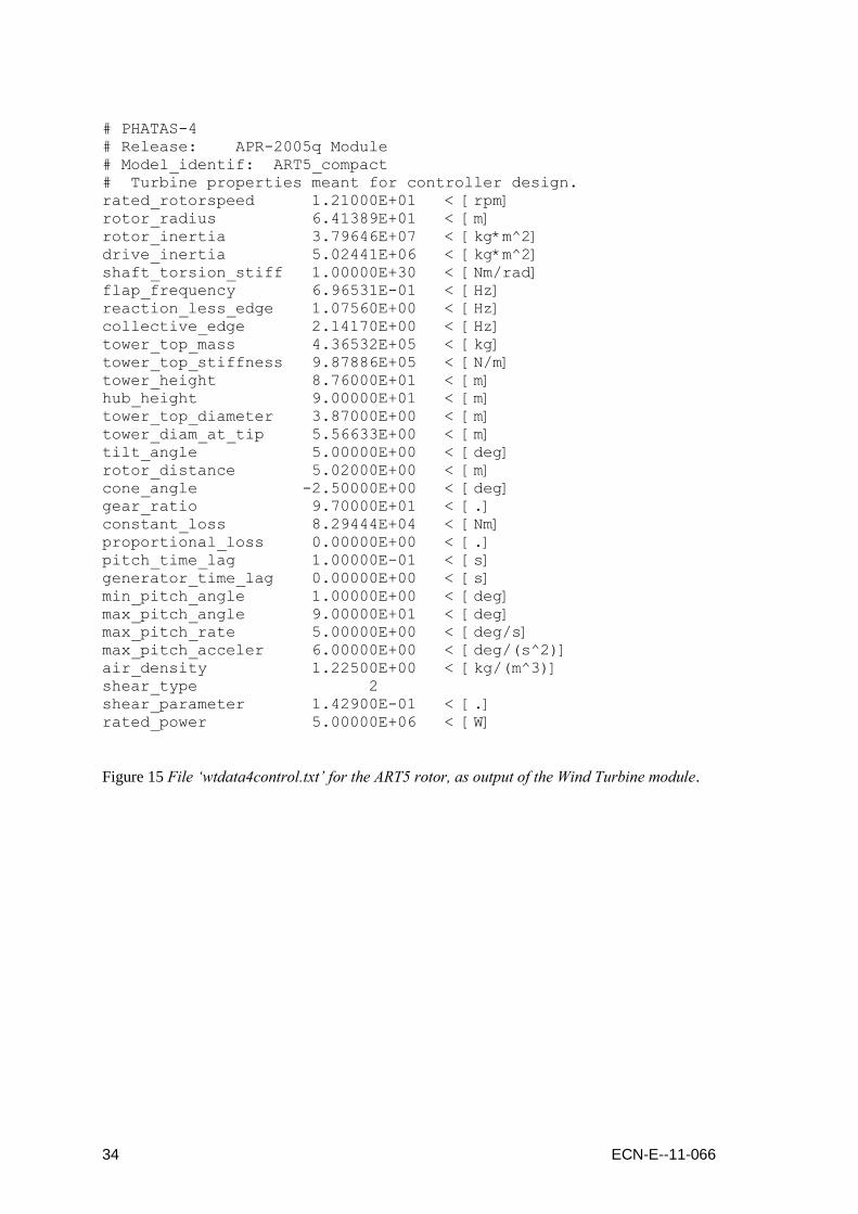
“APR-2005o‟. ............................................................................................ 33 Figure 15 File „wtdata4control.txt‟ for the ART5 rotor, as output of the Wind Turbine
module. ..................................................................................................... 34

4 ECN-E--11-066
Summary
The program Phatas is developed at ECN wind energy for the design and analysis of horizontal
axis wind turbines. Phatas is part of the wind turbine design package Focus which is developed
by WMC. In addition Phatas is re-structured such that it can be called as a module by existing
computer programs for the (hydro-) dynamics of a floating support.
A verification is performed by comparison of results calculated with the former Phatas release
“APR-2005n”, with the current release “APR-2005o” and with the Wind Turbine module. These
calculations are done for the 5MW ART5 wind turbine. In addition to the common practise for
wind turbine design calculations, also the blade torsional deformation is included.
The comparisons start with a calculation of the aerodynamic rotor coefficients which show good
agreement. Next the overspeed analysis is performed with the 3 Phatas versions which show the
same rotor speed at which flutter occurs. Finally the fatigue load sets are calculated and a com-
parison is done on basis of the fatigue equivalent bending moments in the main parts of the
wind turbine structure. The calculations with the Wind Turbine module were performed without
tower bending deformation, because this was not yet fully developed in combination with (pos-
sible) motions of the support.
The aerodynamic coefficients and the overspeed analyses were also calculated with the current
Phatas release for a 10x up-scaled and a 100x down-scaled model of the ART5 wind turbine.
The results of the comparisons show that the Phatas code is robust for a wind turbine dimension
ranging from 1.3m diameter to 1300m diameter. If the calculated results for the up-scaled and
down scaled wind turbine models are scaled back, then they show reasonable agreement with
the results calculated for the un-scaled ART5 wind turbine. The comparisons of the results cal-
culated with the different Phatas versions and with the Wind Turbine module show that they are
close to each other. The minor differences in the calculated fatigue equivalent moment cycles
between release “APR-2005n” and “APR-2005o” may be due to the improvements that are is-
sued in release “APR-2005o”.
Finally it can be concluded that apart from the fact that tower dynamics can not yet be used in
the Wind Turbine module the aerodynamic and structural dynamic response is the same as cal-
culated with the conventional Phatas program.
ECN-E--11-066 5
1. Introduction
Phatas has been developed for the design and analysis of horizontal axis wind turbines. Since
several years Phatas has been applied for the design of commercial wind turbines. Last years it
is also part of the wind turbine design package Focus6. A manual for Phatas is given in [1].
Recently the structural dynamics code of Phatas is made modular to allow coupling with pro-
grams for the motions of floating bodies.
The use of Phatas by several institutes and manufacturers for the design and development of
wind turbines make it necessary to perform some validations that can be published.
This document reports on validations based on a non-existing design of a 128m diameter 5MW
wind turbine that is also used for research purposes. The global characteristics of this design are
reported in Appendix A.
The validations are performed by calculations with different Phatas releases. The results are
compared and reported here. These releases are “APR-2005n” that is issued in April 2011, and
“APR-2005o” that is issued in December 2011.
The calculations are also done with the Wind Turbine module „WTmodule.dll‟ and a program
„wtquake.exe‟. The interface of the „WTmodule.dll‟ is described in appendix A of [2]. The pro-
gram „wtquake.exe‟ is a program that calls the Wind Turbine module and applies a prescribed
motion to the tower base. This can be used e.g.\ to calculate the response on earthquake mo-
tions.
For the comparisons reported in this document the applied motion is simply a constant position,
so with zero velocities and zero accelerations. Tests of the Wind Turbine module with applied
motions are reported separately, see [3].
In addition, calculations are also performed for:
A 10 times up-scaled model of the ART5 rotor. Here all material properties (mass den-
sity, Young‟s modulus of elasticity etcetera) are kept constant. The aerodynamics have
the same characteristics by scaling all velocities down with factor 10, and likewise
“stretching” the time scale with factor 10. The resulting structural dynamic response is
only comparable (after scaling) if the gravity constant is divided with a factor 10. The
latter is done in a specific Phatas release. Verification with a 10 times up-scaled model
shows whether the numerical model will not run into e.g. overflow and whether the re-
sults for large (future) rotors are still consistent.
A 100 times down-scaled model of the ART5 rotor. A down-scaling of 100 (instead of
10) was chosen such that the model has the dimensions that are representative for wind
turbine models. As for the “up-scaled” calculations, a specific Phatas version has been
compiled with gravity constant 981.0.
A global description and model comparison of the up- and down-scaled models is reported in
Appendix B.
Several comparisons are performed. Chapter 2 reports on the comparison of the Cp-lambda-
theta calculations, also called “rotor characteristics”.
Chapter 3 reports on the so-called „overspeed analysis‟. This analysis is a calculation of an
idling rotor with fixed pitch angle for an increased wind speed. By including blade torsional de-
formation (together with the conventional flap bending deformation) the response of this calcu-
lation may show the so-called „flutter speed‟. For the comparisons reported here this „overspeed
analysis‟ is done for a rigid tower.
Chapter 4 reports on a comparison of the response for a stepwise increasing wind velocity. This
response is used to verify the proper functioning of the controller. The controller used here is

6 ECN-E--11-066
the „internal‟ model in Phatas of a simple P-D algorithm for pitch-to-vane controlled variable
speed wind turbines.
Chapter 5 reports on the calculation of an IEC ed.2 [4] fatigue load set. Because the scaling of
the turbulent wind loading requires some modifications of the program SWIFT and the load
case preprocessor „lcprep‟ the fatigue load sets are not calculated for the 10 times up-scaled and
the 100 times down-scaled model of the ART5 rotor.
Finally Chapter 6 contains some concluding remarks.
ECN-E--11-066 7
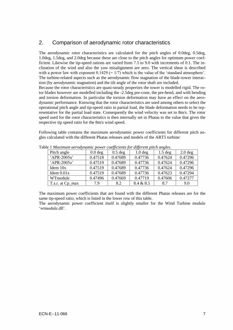
2. Comparison of aerodynamic rotor characteristics
The aerodynamic rotor characteristics are calculated for the pitch angles of 0.0deg, 0.5deg,
1.0deg, 1.5deg, and 2.0deg because these are close to the pitch angles for optimum power coef-
ficient. Likewise the tip-speed rations are varied from 7.5 to 9.0 with increments of 0.1. The in-
clination of the wind and also the yaw misalignment are zero. The vertical shear is described
with a power law with exponent 0.1429 (= 1/7) which is the value of the „standard atmosphere‟.
The turbine-related aspects such as the aerodynamic flow stagnation of the blade-tower interac-
tion (by aerodynamic stagnation) and the tilt angle of the rotor shaft are included.
Because the rotor characteristics are quasi-steady properties the tower is modelled rigid. The ro-
tor blades however are modelled including the -2.5deg pre-cone, the pre-bend, and with bending
and torsion deformation. In particular the torsion deformation may have an effect on the aero-
dynamic performance. Knowing that the rotor characteristics are used among others to select the
operational pitch angle and tip-speed ratio in partial load, the blade deformation needs to be rep-
resentative for the partial load state. Consequently the wind velocity was set to 8m/s. The rotor
speed used for the rotor characteristics is then internally set in Phatas to the value that gives the
respective tip speed ratio for the 8m/s wind speed.
Following table contains the maximum aerodynamic power coefficients for different pitch an-
gles calculated with the different Phatas releases and models of the ART5 turbine:
Table 1 Maximum aerodynamic power coefficients for different pitch angles.
Pitch angle 0.0 deg 0.5 deg 1.0 deg 1.5 deg 2.0 deg
„APR-2005n‟ 0.47518 0.47689 0.47736 0.47624 0.47296
„APR-2005o‟ 0.47519 0.47689 0.47736 0.47624 0.47296
Idem 10x 0.47519 0.47689 0.47736 0.47624 0.47296
Idem 0.01x 0.47519 0.47689 0.47736 0.47623 0.47294
WTmodule 0.47496 0.47669 0.47719 0.47606 0.47277
T.s.r. at Cp_max 7.9 8.2 8.4 & 8.5 8.7 9.0
The maximum power coefficients that are found with the different Phatas releases are for the
same tip-speed ratio, which is listed in the lower row of this table.
The aerodynamic power coefficient itself is slightly smaller for the Wind Turbine module
„wtmodule.dll‟.

8 ECN-E--11-066
ECN-E--11-066 9
3. Comparison of overspeed analyses
Following the laws of proportional scaling –„square cube law‟- the mass of structures increases
with the dimension to the power 3. For the same wind velocity the energy yield scales with the
2-nd power of the dimension which would make large wind turbine structures less material effi-
cient. Rotor blade manufacturers try to „fight‟ this 3-rd power increase of the blade mass by us-
ing a material efficient design, a more slender structure and sophisticated controllers. The more
slender blade designs involve more flexibilities. Consequently more effort is spent on the aeroe-
lastic analysis of wind turbine rotors with a diameter more than 100m. One of the phenomenas
to be investigated is the rotor speed at which the rotor blade gets a growing vibration that is fed
by instationary aerodynamic loading. For aircraft wings this is often a flap-torsion vibration,
also called „flutter‟.
The load case preprocessor „lcprep‟ that is provided with Phatas also generates an input file for
the so-called „overspeed analysis‟. This load case describes the speed of an idling rotor in re-
sponse to an increasing wind velocity. The pitch angle is fixed to an angle that is 8deg more
than the minimum pitch angle for normal operation.
With the Phatas releases mentioned in the introduction in Chapter 1 the overspeed analysis is
performed for the ART5 rotor blades. Here the time increment was set to 0.004s. From the algo-
rithm in Phatas it is known that for this time increment all vibrations with a frequency up to
10.8Hz have a numerical damping of maximum 1%.
The blade torsional frequency is 11.52Hz which means that a torsional vibration is modelled
with a numerical damping of (11.52/10.8)3 % = 1.2%.
The model for correction of the lift coefficient for the effects of rotation is set „ON‟.
The model for dynamic stall effects is also selected.
Both these models have marginal effect as long as the blade sections operate in the „linear‟ part
of the lift curve (which is attached flow).
The „overspeed analysis‟ is calculated with the blade pitch angles fixed at 8.0deg.
The wind velocity is 4.8m/s and increases from 40.0s to 520s ending at 44.8m/s.
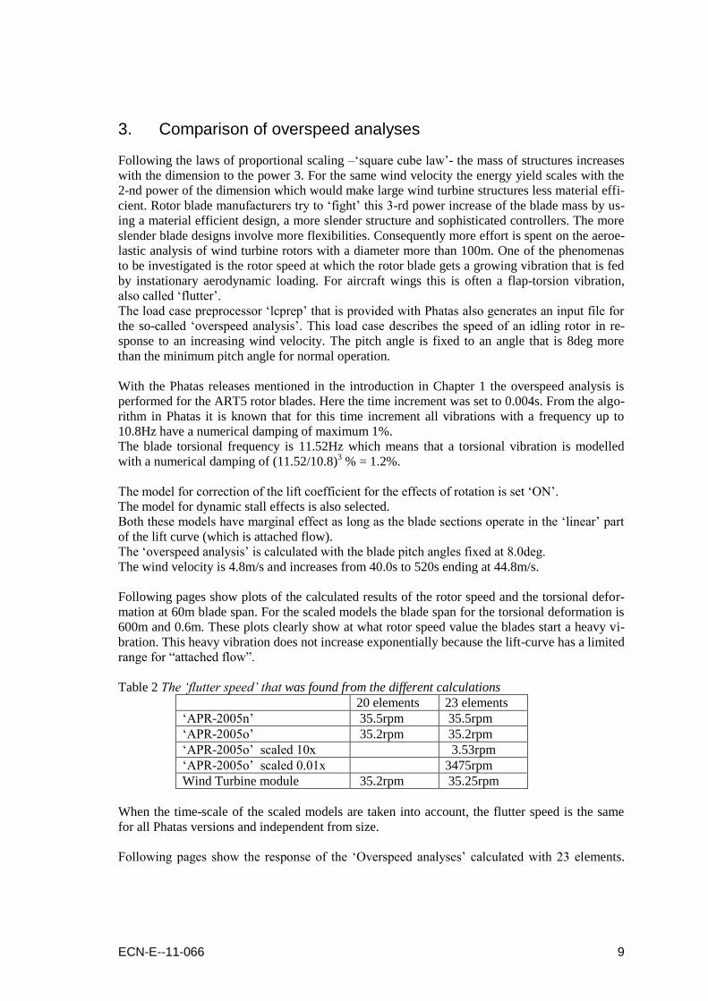
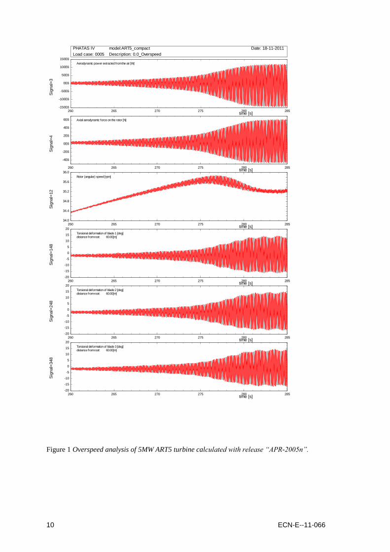
Following pages show plots of the calculated results of the rotor speed and the torsional defor-
mation at 60m blade span. For the scaled models the blade span for the torsional deformation is
600m and 0.6m. These plots clearly show at what rotor speed value the blades start a heavy vi-
bration. This heavy vibration does not increase exponentially because the lift-curve has a limited
range for “attached flow”.
Table 2 The „flutter speed‟ that was found from the different calculations
20 elements 23 elements
„APR-2005n‟ 35.5rpm 35.5rpm
„APR-2005o‟ 35.2rpm 35.2rpm
„APR-2005o‟ scaled 10x 3.53rpm
„APR-2005o‟ scaled 0.01x 3475rpm
Wind Turbine module 35.2rpm 35.25rpm
When the time-scale of the scaled models are taken into account, the flutter speed is the same
for all Phatas versions and independent from size.
Following pages show the response of the „Overspeed analyses‟ calculated with 23 elements.
10 ECN-E--11-066
260 265 270 275 280 285-150E6
-100E6
-50E6
0E6
50E6
100E6
150E6
time [s]
Sig
nal=
3
Aerodynamic power extracted from the air [W]
PHATAS IV model:ART5_compact Date: 18-11-2011
Load case: 0005 Description: 0.0_Overspeed
260 265 270 275 280 285
-4E6
-2E6
0E6
2E6
4E6
6E6
time [s]
Sig
nal=
4
Axial aerodynamic force on the rotor [N]
260 265 270 275 280 28534.0
34.4
34.8
35.2
35.6
36.0
time [s]
Sig
nal=
12
Rotor (angular) speed [rpm]
260 265 270 275 280 285-20
-15
-10
-5
0
5
10
15
20
time [s]
Sig
nal=
148
Torsional deformation of blade 1 [deg]distance from root: 60.00[m]
260 265 270 275 280 285-20
-15
-10
-5
0
5
10
15
20
time [s]
Sig
nal=
248
Torsional deformation of blade 2 [deg]distance from root: 60.00[m]
260 265 270 275 280 285-20
-15
-10
-5
0
5
10
15
20
time [s]
Sig
nal=
348
Torsional deformation of blade 3 [deg]distance from root: 60.00[m]
Figure 1 Overspeed analysis of 5MW ART5 turbine calculated with release “APR-2005n”.

ECN-E--11-066 11
255 260 265 270 275 280-150E6
-100E6
-50E6
0E6
50E6
100E6
150E6
time [s]
Sig
nal=
3
Aerodynamic power extracted from the air [W]
PHATAS IV model:ART5_compact Date: 21-11-2011
Load case: 0005 Description: 0.0_Overspeed
255 260 265 270 275 280
-4E6
-2E6
0E6
2E6
4E6
6E6
time [s]
Sig
nal=
4
Axial aerodynamic force on the rotor [N]
255 260 265 270 275 28033.6
34.0
34.4
34.8
35.2
35.6
time [s]
Sig
nal=
12
Rotor (angular) speed [rpm]
255 260 265 270 275 280-20
-15
-10
-5
0
5
10
15
20
time [s]
Sig
nal=
148
Torsional deformation of blade 1 [deg]distance from root: 60.00[m]
255 260 265 270 275 280-20
-15
-10
-5
0
5
10
15
20
time [s]
Sig
nal=
248
Torsional deformation of blade 2 [deg]distance from root: 60.00[m]
255 260 265 270 275 280-20
-15
-10
-5
0
5
10
15
20
time [s]
Sig
nal=
348
Torsional deformation of blade 3 [deg]distance from root: 60.00[m]
Figure 2 Overspeed analysis of 5MW ART5 turbine calculated with release “APR-2005o”.

12 ECN-E--11-066
2620 2640 2660 2680 2700 2720 2740 2760 2780 2800 2820 2840-15E9
-10E9
-5E9
0E9
5E9
10E9
15E9
time [s]
Sig
nal=
3
Aerodynamic power extracted from the air [W]
PHATAS IV model:ART_500MW Date: 05-12-2011
Load case: 0005 Description: 0.0_Overspeed
2620 2640 2660 2680 2700 2720 2740 2760 2780 2800 2820 2840
-400E6
-200E6
0E6
200E6
400E6
600E6
time [s]
Sig
nal=
4
Axial aerodynamic force on the rotor [N]
2620 2640 2660 2680 2700 2720 2740 2760 2780 2800 2820 28403.42
3.44
3.46
3.48
3.50
3.52
3.54
3.56
time [s]
Sig
nal=
12
Rotor (angular) speed [rpm]
2620 2640 2660 2680 2700 2720 2740 2760 2780 2800 2820 2840-20
-15
-10
-5
0
5
10
15
20
time [s]
Sig
nal=
148
Torsional deformation of blade 1 [deg]distance from root: 600.00[m]
2620 2640 2660 2680 2700 2720 2740 2760 2780 2800 2820 2840-20
-15
-10
-5
0
5
10
15
20
time [s]
Sig
nal=
248
Torsional deformation of blade 2 [deg]distance from root: 600.00[m]
2620 2640 2660 2680 2700 2720 2740 2760 2780 2800 2820 2840-20
-15
-10
-5
0
5
10
15
20
time [s]
Sig
nal=
348
Torsional deformation of blade 3 [deg]distance from root: 600.00[m]
Figure 3 Overspeed analysis of 500MW ART5 turbine calculated with release “APR-2005o”.

ECN-E--11-066 13
2.20 2.25 2.30 2.35 2.40 2.45 2.50-12000
-8000
-4000
0
4000
8000
time [s]
Sig
nal=
3
Aerodynamic power extracted from the air [W]
PHATAS IV model:ART5_compact Date: 22-11-2011
Load case: 0005 Description: 0.0_Overspeed
2.20 2.25 2.30 2.35 2.40 2.45 2.50
-400
-200
0
200
400
600
time [s]
Sig
nal=
4
Axial aerodynamic force on the rotor [N]
2.20 2.25 2.30 2.35 2.40 2.45 2.503280
3320
3360
3400
3440
3480
time [s]
Sig
nal=
12
Rotor (angular) speed [rpm]
2.20 2.25 2.30 2.35 2.40 2.45 2.50-20
-15
-10
-5
0
5
10
15
time [s]
Sig
nal=
148
Torsional deformation of blade 1 [deg]distance from root: 0.60[m]
2.20 2.25 2.30 2.35 2.40 2.45 2.50-20
-15
-10
-5
0
5
10
15
20
time [s]
Sig
nal=
248
Torsional deformation of blade 2 [deg]distance from root: 0.60[m]
2.20 2.25 2.30 2.35 2.40 2.45 2.50-20
-15
-10
-5
0
5
10
15
time [s]
Sig
nal=
348
Torsional deformation of blade 3 [deg]distance from root: 0.60[m]
Figure 4 Overspeed analysis of 500W ART5 turbine calculated with release “APR-2005o”.

14 ECN-E--11-066
260 265 270 275 280 285-150E6
-100E6
-50E6
0E6
50E6
100E6
150E6
time [s]
Sig
nal=
3
Aerodynamic power extracted from the air [W]
PHATAS IV model:ART5_compact Date: 20-11-2011
Load case: 0005 Description: 0.0_Overspeed
260 265 270 275 280 285
-4E6
-2E6
0E6
2E6
4E6
6E6
time [s]
Sig
nal=
4
Axial aerodynamic force on the rotor [N]
260 265 270 275 280 28534.0
34.4
34.8
35.2
35.6
time [s]
Sig
nal=
12
Rotor (angular) speed [rpm]
260 265 270 275 280 285-20
-15
-10
-5
0
5
10
15
20
time [s]
Sig
nal=
148
Torsional deformation of blade 1 [deg]distance from root: 60.00[m]
260 265 270 275 280 285-20
-15
-10
-5
0
5
10
15
20
time [s]
Sig
nal=
248
Torsional deformation of blade 2 [deg]distance from root: 60.00[m]
260 265 270 275 280 285-20
-15
-10
-5
0
5
10
15
20
time [s]
Sig
nal=
348
Torsional deformation of blade 3 [deg]distance from root: 60.00[m]
Figure 5 Overspeed analysis of 5MW ART5 turbine calculated with the Wind Turbine module.

ECN-E--11-066 15
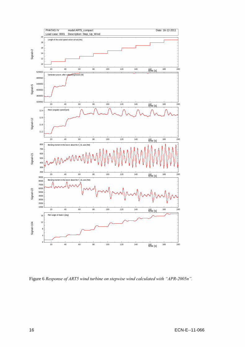
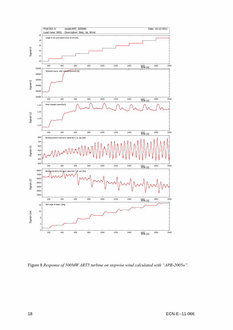
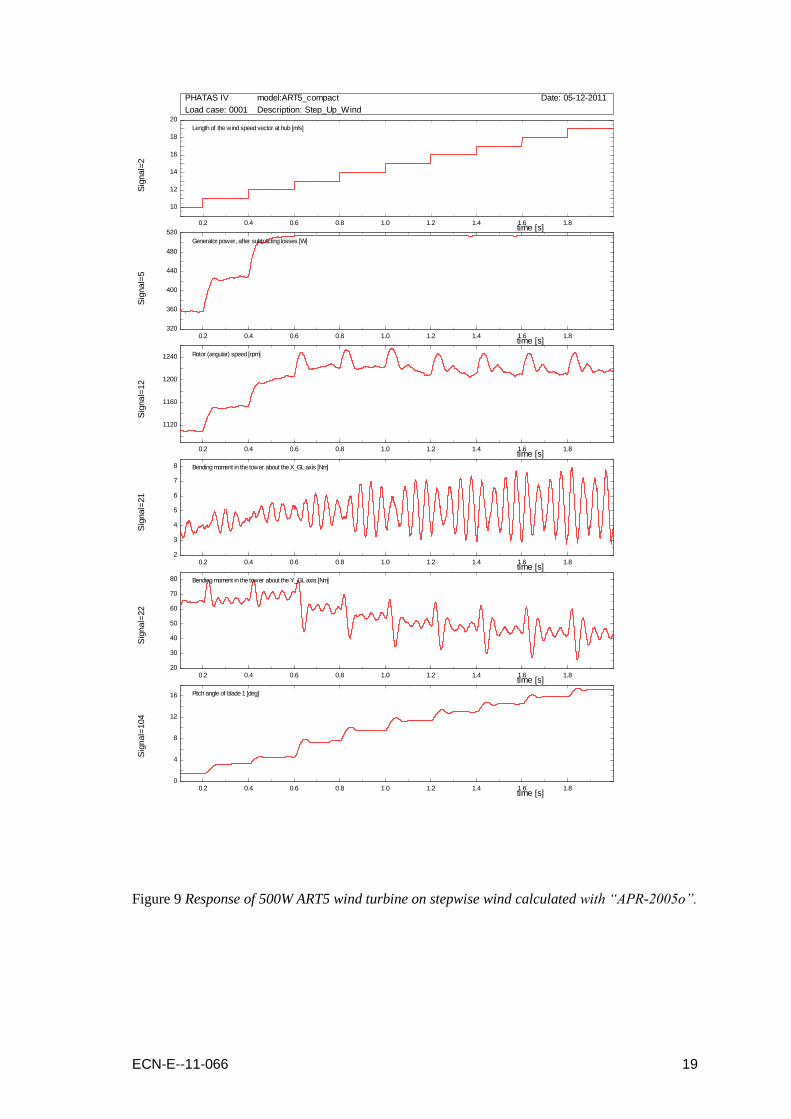
4. Comparison of response on stepwise increasing wind
Phatas offers an option to apply a stepwise increasing wind velocity. This wind can be used to
evaluate the (step-) response of the operational controller. This response is evaluated for the
simple built-in P-D controller of Phatas. The controller settings are:
Average time 0.8s (1/6 of a revolution)
Proportional_gain 0.3
Differential_gain 2.0
Gain scheduling factor 1./(1. + 0.16*(Pitch – Pitch_min) ) „Pitch‟ in [deg]
Threshold value 0.5deg/s.
Time delay of pitch actuator: 0.1s.
Maximum pitch_rate 5.0deg/s.
Maximum pitch acceleration 6.0deg/s2
These controller settings are also applied for the calculations with the Wind Turbine module.
The wind is increasing from 10m/s to 20m/s with steps of 1.0m/s.
Each wind velocity is maintained during 20s.
Plots of the calculated response are shown on the following pages. These responses are highly
similar except for the response calculated with the Wind Turbine module which is calculated
without tower dynamics, see Figure 10.
A scoping calculation of this step-response with release “APR-2005o” showed similar response
as calculated with the Wind Turbine module in Figure 10. It was thus concluded that the differ-
ent response in Figure 10 is due to the omission of tower dynamics.
16 ECN-E--11-066
20 40 60 80 100 120 140 160 180 200
10
12
14
16
18
20
time [s]
Sig
nal=
2
Length of the wind speed vector at hub [m/s]
PHATAS IV model:ART5_compact Date: 16-12-2011
Load case: 0001 Description: Step_Up_Wind
20 40 60 80 100 120 140 160 180 2003200E3
3600E3
4000E3
4400E3
4800E3
5200E3
time [s]
Sig
nal=
5
Generator power, after subtracting losses [W]
20 40 60 80 100 120 140 160 180 200
11.2
11.6
12.0
12.4
time [s]
Sig
nal=
12
Rotor (angular) speed [rpm]
20 40 60 80 100 120 140 160 180 2002E6
3E6
4E6
5E6
6E6
7E6
8E6
time [s]
Sig
nal=
21
Bending moment in the tower about the X_GL axis [Nm]
20 40 60 80 100 120 140 160 180 20010E6
20E6
30E6
40E6
50E6
60E6
70E6
80E6
90E6
time [s]
Sig
nal=
22
Bending moment in the tower about the Y_GL axis [Nm]
20 40 60 80 100 120 140 160 180 2000
4
8
12
16
time [s]
Sig
nal=
104
Pitch angle of blade 1 [deg]
Figure 6 Response of ART5 wind turbine on stepwise wind calculated with “APR-2005n”.

ECN-E--11-066 17
20 40 60 80 100 120 140 160 180 200
10
12
14
16
18
20
time [s]
Sig
nal=
2
Length of the wind speed vector at hub [m/s]
PHATAS IV model:ART5_compact Date: 16-12-2011
Load case: 0001 Description: Step_Up_Wind
20 40 60 80 100 120 140 160 180 2003200E3
3600E3
4000E3
4400E3
4800E3
5200E3
time [s]
Sig
nal=
5
Generator power, after subtracting losses [W]
20 40 60 80 100 120 140 160 180 200
11.2
11.6
12.0
12.4
time [s]
Sig
nal=
12
Rotor (angular) speed [rpm]
20 40 60 80 100 120 140 160 180 2002E6
3E6
4E6
5E6
6E6
7E6
8E6
time [s]
Sig
nal=
21
Bending moment in the tower about the X_GL axis [Nm]
20 40 60 80 100 120 140 160 180 200
20E6
30E6
40E6
50E6
60E6
70E6
80E6
time [s]
Sig
nal=
22
Bending moment in the tower about the Y_GL axis [Nm]
20 40 60 80 100 120 140 160 180 2000
4
8
12
16
time [s]
Sig
nal=
104
Pitch angle of blade 1 [deg]
Figure 7 Response of ART5 wind turbine on stepwise wind calculated with “APR-2005o”.
18 ECN-E--11-066
200 400 600 800 1000 1200 1400 1600 1800 2000
10
12
14
16
18
20
time [s]
Sig
nal=
2
Length of the wind speed vector at hub [m/s]
PHATAS IV model:ART_500MW Date: 16-12-2011
Load case: 0001 Description: Step_Up_Wind
200 400 600 800 1000 1200 1400 1600 1800 2000320E6
360E6
400E6
440E6
480E6
520E6
time [s]
Sig
nal=
5
Generator power, after subtracting losses [W]
200 400 600 800 1000 1200 1400 1600 1800 2000
1.12
1.16
1.20
1.24
time [s]
Sig
nal=
12
Rotor (angular) speed [rpm]
200 400 600 800 1000 1200 1400 1600 1800 20002E9
3E9
4E9
5E9
6E9
7E9
8E9
time [s]
Sig
nal=
21
Bending moment in the tower about the X_GL axis [Nm]
200 400 600 800 1000 1200 1400 1600 1800 2000
20E9
30E9
40E9
50E9
60E9
70E9
80E9
time [s]
Sig
nal=
22
Bending moment in the tower about the Y_GL axis [Nm]
200 400 600 800 1000 1200 1400 1600 1800 20000
4
8
12
16
time [s]
Sig
nal=
104
Pitch angle of blade 1 [deg]
Figure 8 Response of 500MW ART5 turbine on stepwise wind calculated with “APR-2005o”.
ECN-E--11-066 19
0.2 0.4 0.6 0.8 1.0 1.2 1.4 1.6 1.8
10
12
14
16
18
20
time [s]
Sig
nal=
2
Length of the wind speed vector at hub [m/s]
PHATAS IV model:ART5_compact Date: 05-12-2011
Load case: 0001 Description: Step_Up_Wind
0.2 0.4 0.6 0.8 1.0 1.2 1.4 1.6 1.8320
360
400
440
480
520
time [s]
Sig
nal=
5
Generator power, after subtracting losses [W]
0.2 0.4 0.6 0.8 1.0 1.2 1.4 1.6 1.8
1120
1160
1200
1240
time [s]
Sig
nal=
12
Rotor (angular) speed [rpm]
0.2 0.4 0.6 0.8 1.0 1.2 1.4 1.6 1.82
3
4
5
6
7
8
time [s]
Sig
nal=
21
Bending moment in the tower about the X_GL axis [Nm]
0.2 0.4 0.6 0.8 1.0 1.2 1.4 1.6 1.820
30
40
50
60
70
80
time [s]
Sig
nal=
22
Bending moment in the tower about the Y_GL axis [Nm]
0.2 0.4 0.6 0.8 1.0 1.2 1.4 1.6 1.80
4
8
12
16
time [s]
Sig
nal=
104
Pitch angle of blade 1 [deg]
Figure 9 Response of 500W ART5 wind turbine on stepwise wind calculated with “APR-2005o”.

20 ECN-E--11-066
20 40 60 80 100 120 140 160 180 200
10
12
14
16
18
20
time [s]
Sig
nal=
2
Length of the wind speed vector at hub [m/s]
PHATAS IV model:ART5_compact Date: 05-12-2011
Load case: 0001 Description: Step_Up_Wind
20 40 60 80 100 120 140 160 180 2003200E3
3600E3
4000E3
4400E3
4800E3
5200E3
time [s]
Sig
nal=
5
Generator power, after subtracting losses [W]
20 40 60 80 100 120 140 160 180 200
11.2
11.6
12.0
12.4
time [s]
Sig
nal=
12
Rotor (angular) speed [rpm]
20 40 60 80 100 120 140 160 180 200
3000E3
4000E3
5000E3
6000E3
7000E3
time [s]
Sig
nal=
21
Bending moment in the tower about the X_GL axis [Nm]
20 40 60 80 100 120 140 160 180 200
30E6
40E6
50E6
60E6
70E6
80E6
time [s]
Sig
nal=
22
Bending moment in the tower about the Y_GL axis [Nm]
20 40 60 80 100 120 140 160 180 2000
4
8
12
16
time [s]
Sig
nal=
104
Pitch angle of blade 1 [deg]
Figure 10 Response of ART5 wind turbine on stepwise wind calculated with „WTmodule.dll‟.

ECN-E--11-066 21
5. Comparison of fatigue load set properties
A Class IIA Fatigue load set following IEC ed.2 [4] is being calculated.
This load set is not calculated for the 10x up-scaled and the 100x down-scaled versions of the
ART5 wind turbine model, because the load case input files that are generated with „lcprep‟ do
not scale in all properties with wind turbine dimension. This means for example that the time
period of the gusts is independent from wind turbine dimension following IEC ed.2 [4].
Table 3 Some of the statistical properties of the production load cases.
“APR-2005n” “APR-2005o” Wind Turbine module
Maximum rotor speed [rpm] 13.846 (0240) 13.850 (0240) 13.871 (0222)
Maximum axial force [kN] 878.5 (0132) 879.9 (0120) 911.4 (0152)
Maximum tip displacement [m] 6.665 (0150) 6.646 (0150) 6.624 (0150)
Smallest tip-tower clearance [m] 5.237 (0120) 5.245 (0120) 5.090 (0120)
Maximum pitch rate [deg/s] 2.848 (0240) 2.855 (0240) 2.582 (0240)
Maximum top acceleration [m/s2] 1.7761 (0240) 1.7717 (0250) Tower is rigid
The numbers between brackets are the load case numbers for which the value is traced.
Except for the maximum tower top acceleration, these largest/smallest properties from release
“APR-2005n” and “APR-2005o” were found for the same load case. To some extent this is also
the case for the largest production properties that are calculated with the Wind Turbine module.
The statistical properties of release “APR-2005n” and “APR-2005o” show differences. The
largest blade deformation seems to be a bit stronger when calculated with release “APR-2005o”.
This is due to the fact that release “APR-2005o” has a better solver for the dynamic equations
for blade bending, and consequently gives better converged solutions. With these “better con-
verged” solutions the controller input for rotor speed is slightly smoother and the controller ac-
tions generally tend to exceed the “threshold value” somewhat later.
The calculations with the Wind Turbine module are still done without modelling tower bending.
The „rigid‟ model for tower dynamics gives a larger axial force, and likewise a smaller mini-
mum tower clearance. It is surprising that the maximum tip displacement for the rigid tower is
somewhat smaller.
For some locations in the wind turbine model the 5*106 fatigue equivalent load cycles are calcu-
lated. For the steel parts the 5*106 equivalent cycles were calculated for a Goodman damage re-
lation with slope parameter m = 4. For the composite blade root the 10*106 equivalent cycles
were calculated with a slope parameter of m = 9.
Table 4 Some of the fatigue equivalent bending moment cycles.
“APR-2005n” “APR-2005o” Wind Turbine module
Tower base bending Mx [kNm] 40483 40131 29400
Tower base bending My [kNm] 67549 67557 60168
Tower top bending Mx [kNm] 2610 2621 2560
Tower top bending My [kNm] 12231 12213 12273
Tower top bending Mz [kNm] 12928 12917 12186
Shaft bending My [kNm] 14443 14445 14779
Shaft bending Mz [kNm] 14397 14388 14782
Flatwise blade bending My [kNm] 10420 10405 10481
Edgewise blade bending Mx [kNm] 9843 9869 10009
Blade torsion Mz [kNm] 159.03 157.05 159.0
The fatigue equivalent bending moment cycles for the fatigue load sets calculated with the dif-
ferent versions appear to be similar. The fatigue equivalent tower base bending moment cycles
calculated with the Wind Turbine module are smaller because tower dynamics are not included.

22 ECN-E--11-066
ECN-E--11-066 23
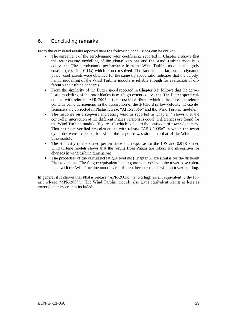
6. Concluding remarks
From the calculated results reported here the following conclusions can be drawn:
The agreement of the aerodynamic rotor coefficients reported in Chapter 2 shows that
the aerodynamic modelling of the Phatas versions and the Wind Turbine module is
equivalent. The aerodynamic performance from the Wind Turbine module is slightly
smaller (less than 0.1%) which is not resolved. The fact that the largest aerodynamic
power coefficients were obtained for the same tip speed ratio indicates that the aerody-
namic modelling of the Wind Turbine module is reliable enough for evaluation of dif-
ferent wind turbine concepts.
From the similarity of the flutter speed reported in Chapter 3 it follows that the aeroe-
lastic modelling of the rotor blades is to a high extent equivalent. The flutter speed cal-
culated with release “APR-2005n” is somewhat different which is because this release
contains some deficiencies in the description of the 3/4chord inflow velocity. These de-
ficiencies are corrected in Phatas release “APR-2005o” and the Wind Turbine module.
The response on a stepwise increasing wind as reported in Chapter 4 shows that the
controller interaction of the different Phatas versions is equal. Differences are found for
the Wind Turbine module (Figure 10) which is due to the omission of tower dynamics.
This has been verified by calculations with release “APR-2005o” in which the tower
dynamics were excluded, for which the response was similar to that of the Wind Tur-
bine module.
The similarity of the scaled performance and response for the 10X and 0.01X scaled
wind turbine models shows that the results from Phatas are robust and insensitive for
changes in wind turbine dimensions.
The properties of the calculated fatigue load set (Chapter 5) are similar for the different
Phatas versions. The fatigue equivalent bending moment cycles in the tower base calcu-
lated with the Wind Turbine module are different because this is without tower bending.
In general it is shown that Phatas release “APR-2005o” is to a high extent equivalent to the for-
mer release “APR-2005n”. The Wind Turbine module also gives equivalent results as long as
tower dynamics are not included.

24 ECN-E--11-066

ECN-E--11-066 25
References
[1] Lindenburg, C.:
„PHATAS Release :APR-2005o” USER‟S MANUAL‟,
ECN-I--05-005 r9, ECN, Petten, 2011 (Initially published in 2005).
[2] Gueydon, S., C. Lindenburg and J.M. Peeringa, (2011a):
„Coupling of Phatas to aNySIM‟.
Marin, 2011.
[3] Lindenburg, C.;
„Verification of the Wind Turbine module‟.
ECN-X--11-146, ECN Petten, December 2011.
[4] International Electrotechnical Commission;
„Wind turbine generator systems- Part 1: Safety requirements‟.
INTERNATIONAL STANDARD IEC 61400-1 Second edition, 1999-02.

26 ECN-E--11-066
ECN-E--11-066 27
Appendix A. The ART5 turbine model used for the verifications
The ART5 rotor model was developed by Koen Boorsma. The basis of this development was
the former Dowec 6MW wind turbine model and the 5MW RWT model of the UpWind project.
The development of the ART5 rotor model aimed at an aerodynamic rotor design that is more
representative for well-designed modern wind turbine rotors.
The rated rotational speed is 12.1rpm and the rated generator power is 5MW.
A.1 Specific settings for the ‘compact’ ART5 model used here.
The tables with input properties are condensed such that the tables with blade properties and
with the generator Q-n curve does not contain more than 12 records. This „compact‟ model was
edited such that the overall properties of the rotor such as mass, aerodynamic properties, and
blade frequencies are conserved to a large extent.
For the purpose of verification and also for the purpose of demonstrations and courses this com-
pact model is also sufficient and maybe more „handsome‟.
The tower is a tubular tower of 107.6m long. With 20.0m water depth and 2.4m “hub_location‟
the „hub_height‟ of the ART5 model is 90.0m above the water level.
The foundation flexibility is modelled with a rotation-stiffness of 4.5E+10 Nm/rad.
Tower dynamics are modelled with „bending_modes 3‟. For conventional land-based wind tur-
bine this input is set to 2. For calculations including wave loading on the tower more modes are
used to give a realistic dynamic response.
The smallest rotor speed of the generator torque-speed curve is increased to 5.0rpm. This is nec-
essary to avoid excitation of the tower bending by the 3P blade passing.
The controller is modelled with the „internal‟ P-D algorithm of Phatas for pitch-to-vane con-
trolled variable speed wind turbines. The pitch angle in partial load was set to 1.0deg, which is
the value with the largest calculated Cp. The full-load controller settings are:
No of pulses on the speed sensor: 8192.
Eccentricity of the speed sensor: 0.0005.
Average time on input of rotor speed: 0.8s.
Proportional gain: 0.3.
Differential gain: 2.0.
Gain scheduling factor: 0.16.
Threshold value: 0.5deg/s.
Delay of the pitch actuator: 0.1s; modelled with first order differential equation.
Maximum pitch control rate: 5.0deg/s.
Maximum pitch control acceleration: 6.0deg/s2.
Prior to entering the full-load operating state, the blades are pitched slightly to vane to reduce
the axial aerodynamic forces near rated conditions. This „peak shaving‟ pitch strategy starts at
11.0rpm and ends at 11.8rpm with a 4.5deg blade pitch angle.
Blade torsion is modelled. In the conventional design process blade torsion is not required so
far, but for rotors with a diameter more than 100m analyses including blade torsion are gener-
ally done to investigate the aeroelastic stability.
The time increment is 0.02s, which is sufficient to describe dynamics up to the second blade
flapping mode and the „collective edgewise‟ mode. The latter mode is also known as „drive
train‟ mode.

28 ECN-E--11-066
The blade is modelled with 23 elements, which gives an „AIRFOIL MATCHING‟ of 0.975.
The value of the „AIRFOIL MATCHING‟ is listed by Phatas in the *.mdl file.
Blade models with 14, 17, and 20 elements also give a good „AIRFOIL MATCHING‟.
A.2 Specific ART5 model inputs for the Wind Turbine module
The wind turbine module „WTmodule.dll‟ can not read the „tubular-type of input format for the
tower properties. Instead „WTmodule.dll‟ expects a mass and stiffness matrix and a table with
modal properties for the so-called Crag-Bampton modes.
For a rigid foundation an analysis of the ART5 turbine was done with Phatas release “APR-
2005o”. The resulting output file with tower properties „towmod.out‟ contains also the Craig-
Bampton type of modal properties of the tower dynamics. With these properties a tower input
file was modelled. This input file was used for the calculations with the program „wtquake.exe‟
and „wtmodule.dll‟.
ECN-E--11-066 29
Appendix B. Scaled input models of the ART5 turbine model
For verification of the wind turbine design tools it was decided to include analyses with an up-
scaled and a down-scaled model of an existing wind turbine. These analyses show:
1. Whether the design tools such as Phatas do not run into overflow or underflow. This in-
cludes the post processor and to some extent the load case preprocessor.
2. Whether the calculated results remain the same after „scaling back‟.
Initially one may think that a 10 times up-scaled version and a 10 times down-scaled version of
an existing wind turbine gives sufficient proof of the robustness of an analysis program for
variation of dimensions. Assuming that analysis programs such as Phatas are used to analyse
results from wind tunnel measurements for turbine models of the scale of 1 m diameter it was
chosen to scale the ART5 turbine model down with factor 100.
The resulting down-scaled rotor diameter is then 1.28m.
When scaling the dimensions of the ART5 rotor all material properties (mass density, Young‟s
modulus of elasticity etcetera) are kept constant. The aerodynamics have the same characteris-
tics by scaling all velocities down with factor 10, and likewise “stretching” the time scale with
factor 10. The resulting structural dynamic response is only comparable (after scaling) if the
gravity constant is divided with a factor 10. The latter is done in a specific Phatas release. Veri-
fication with a 10 times up-scaled model shows whether the numerical model will not run into
e.g. overflow and whether the results for large (future) rotors are still consistent.
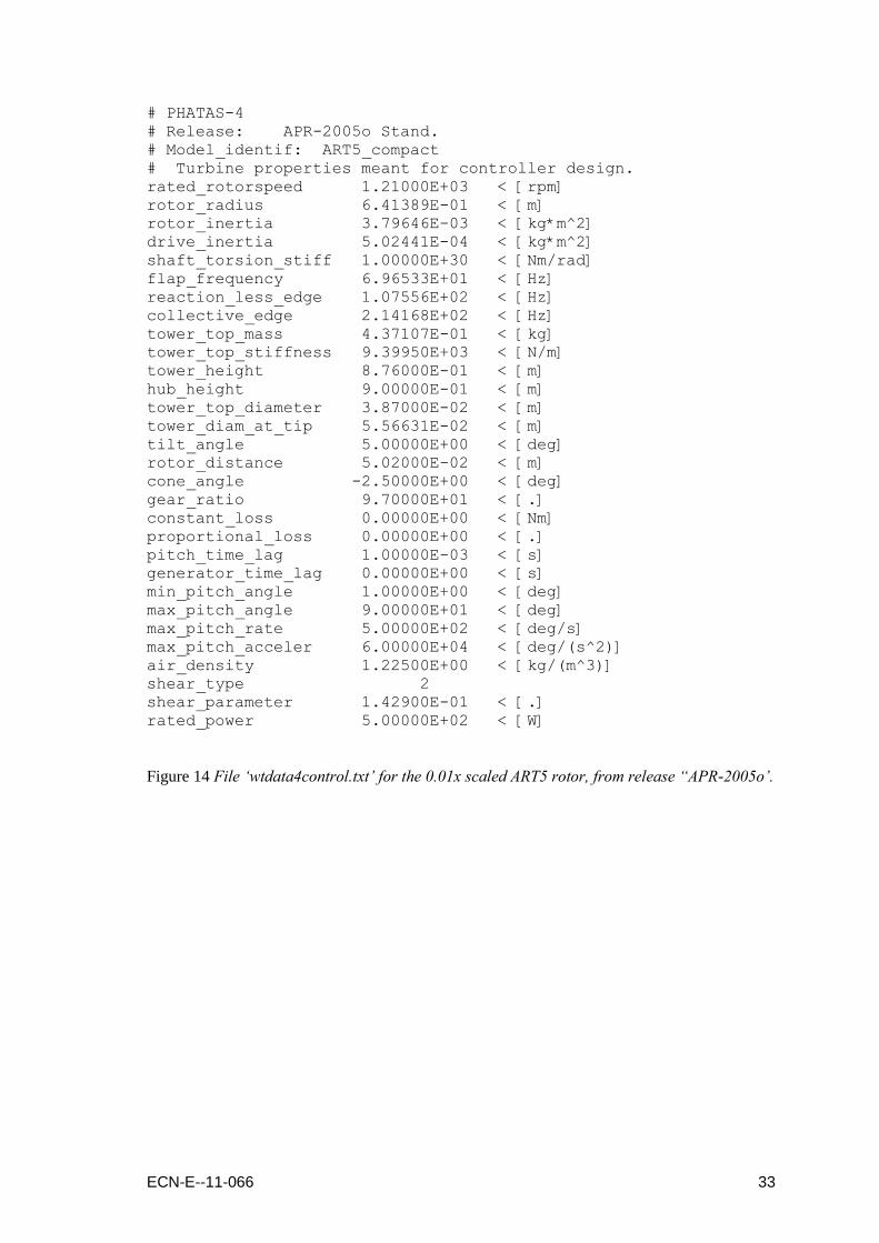
A similar approach is used for scaling the ART5 rotor with a factor 0.01, for which a specific
Phatas code has to be compiled with a gravity constant of 981.0m/s2.
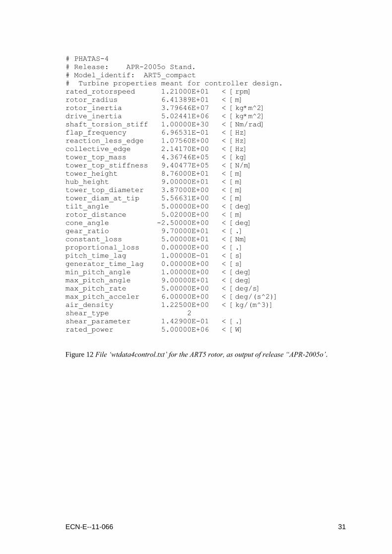
The following pages show the Phatas output files „wtdata4control.txt‟ from Phatas release
“APR-2005o” that contain the global turbine properties that can be used for the design of the
controller. These files are from the calculation of the response on stepwise increasing wind as
reported in Chapter 4. These files are listed for the scaled versions of the ART5 turbine and for
the un-scaled model as output from the different Phatas releases.

30 ECN-E--11-066
# PHATAS-4 # Release: APR-2005n Stand.
# Model_identif: ART5_compact
# Turbine properties meant for controller design.
rated_rotorspeed 1.21000E+01 < [rpm]
rotor_radius 6.41389E+01 < [m]
rotor_inertia 3.79645E+07 < [kg*m^2]
drive_inertia 5.02441E+06 < [kg*m^2]
shaft_torsion_stiff 1.00000E+30 < [Nm/rad]
flap_frequency 6.99858E-01 < [Hz]
reaction_less_edge 1.04749E+00 < [Hz]
collective_edge 2.08967E+00 < [Hz]
tower_top_mass 4.37108E+05 < [kg]
tower_top_stiffness 9.39950E+05 < [N/m]
tower_height 8.76000E+01 < [m]
hub_height 9.00000E+01 < [m]
tower_top_diameter 3.87000E+00 < [m]
tower_diam_at_tip 5.56631E+00 < [m]
tilt_angle 5.00000E+00 < [deg]
rotor_distance 5.02000E+00 < [m]
cone_angle -2.50000E+00 < [deg]
gear_ratio 9.70000E+01 < [.]
constant_loss 5.00000E+01 < [Nm]
proportional_loss 0.00000E+00 < [.]
pitch_time_lag 1.00000E-01 < [s]
generator_time_lag 0.00000E+00 < [s]
min_pitch_angle 1.00000E+00 < [deg]
max_pitch_angle 9.00000E+01 < [deg]
max_pitch_rate 5.00000E+00 < [deg/s]
max_pitch_acceler 6.00000E+00 < [deg/(s^2)]
air_density 1.22500E+00 < [kg/(m^3)]
shear_type 2
shear_parameter 1.42900E-01 < [.]
rated_power 5.00000E+06 < [W]
Figure 11 File „wtdata4control.txt‟ for the ART5 rotor, as output of release “APR-2005n‟.
ECN-E--11-066 31
# PHATAS-4
# Release: APR-2005o Stand.
# Model_identif: ART5_compact
# Turbine properties meant for controller design.
rated_rotorspeed 1.21000E+01 < [rpm]
rotor_radius 6.41389E+01 < [m]
rotor_inertia 3.79646E+07 < [kg*m^2]
drive_inertia 5.02441E+06 < [kg*m^2]
shaft_torsion_stiff 1.00000E+30 < [Nm/rad]
flap_frequency 6.96531E-01 < [Hz]
reaction_less_edge 1.07560E+00 < [Hz]
collective_edge 2.14170E+00 < [Hz]
tower_top_mass 4.36746E+05 < [kg]
tower_top_stiffness 9.40477E+05 < [N/m]
tower_height 8.76000E+01 < [m]
hub_height 9.00000E+01 < [m]
tower_top_diameter 3.87000E+00 < [m]
tower_diam_at_tip 5.56631E+00 < [m]
tilt_angle 5.00000E+00 < [deg]
rotor_distance 5.02000E+00 < [m]
cone_angle -2.50000E+00 < [deg]
gear_ratio 9.70000E+01 < [.]
constant_loss 5.00000E+01 < [Nm]
proportional_loss 0.00000E+00 < [.]
pitch_time_lag 1.00000E-01 < [s]
generator_time_lag 0.00000E+00 < [s]
min_pitch_angle 1.00000E+00 < [deg]
max_pitch_angle 9.00000E+01 < [deg]
max_pitch_rate 5.00000E+00 < [deg/s]
max_pitch_acceler 6.00000E+00 < [deg/(s^2)]
air_density 1.22500E+00 < [kg/(m^3)]
shear_type 2
shear_parameter 1.42900E-01 < [.]
rated_power 5.00000E+06 < [W]
Figure 12 File „wtdata4control.txt‟ for the ART5 rotor, as output of release “APR-2005o‟.

32 ECN-E--11-066
# PHATAS-4
# Model_identif: ART_500MW
# Turbine properties meant for controller design.
rated_rotorspeed 1.21000E+00 < [rpm]
rotor_radius 6.41389E+02 < [m]
rotor_inertia 3.79646E+12 < [kg*m^2]
drive_inertia 5.02441E+11 < [kg*m^2]
shaft_torsion_stiff 1.00000E+30 < [Nm/rad]
flap_frequency 6.96518E-02 < [Hz]
reaction_less_edge 1.07558E-01 < [Hz]
collective_edge 2.14165E-01 < [Hz]
tower_top_mass 4.37112E+08 < [kg]
tower_top_stiffness 9.39969E+06 < [N/m]
tower_height 8.76000E+02 < [m]
hub_height 9.00000E+02 < [m]
tower_top_diameter 3.87000E+01 < [m]
tower_diam_at_tip 5.56631E+01 < [m]
tilt_angle 5.00000E+00 < [deg]
rotor_distance 5.02000E+01 < [m]
cone_angle -2.50000E+00 < [deg]
gear_ratio 9.70000E+01 < [.]
constant_loss 5.00000E+04 < [Nm]
proportional_loss 0.00000E+00 < [.]
pitch_time_lag 1.00000E+00 < [s]
generator_time_lag 0.00000E+00 < [s]
min_pitch_angle 1.00000E+00 < [deg]
max_pitch_angle 9.00000E+01 < [deg]
max_pitch_rate 5.00000E-01 < [deg/s]
max_pitch_acceler 6.00000E-02 < [deg/(s^2)]
air_density 1.22500E+00 < [kg/(m^3)]
shear_type 2
shear_parameter 1.42900E-01 < [.]
rated_power 5.00000E+08 < [W]
Figure 13 File „wtdata4control.txt‟ for the 10x scaled ART5 rotor, from release “APR-2005o‟.
ECN-E--11-066 33
# PHATAS-4
# Release: APR-2005o Stand.
# Model_identif: ART5_compact
# Turbine properties meant for controller design.
rated_rotorspeed 1.21000E+03 < [rpm]
rotor_radius 6.41389E-01 < [m]
rotor_inertia 3.79646E-03 < [kg*m^2]
drive_inertia 5.02441E-04 < [kg*m^2]
shaft_torsion_stiff 1.00000E+30 < [Nm/rad]
flap_frequency 6.96533E+01 < [Hz]
reaction_less_edge 1.07556E+02 < [Hz]
collective_edge 2.14168E+02 < [Hz]
tower_top_mass 4.37107E-01 < [kg]
tower_top_stiffness 9.39950E+03 < [N/m]
tower_height 8.76000E-01 < [m]
hub_height 9.00000E-01 < [m]
tower_top_diameter 3.87000E-02 < [m]
tower_diam_at_tip 5.56631E-02 < [m]
tilt_angle 5.00000E+00 < [deg]
rotor_distance 5.02000E-02 < [m]
cone_angle -2.50000E+00 < [deg]
gear_ratio 9.70000E+01 < [.]
constant_loss 0.00000E+00 < [Nm]
proportional_loss 0.00000E+00 < [.]
pitch_time_lag 1.00000E-03 < [s]
generator_time_lag 0.00000E+00 < [s]
min_pitch_angle 1.00000E+00 < [deg]
max_pitch_angle 9.00000E+01 < [deg]
max_pitch_rate 5.00000E+02 < [deg/s]
max_pitch_acceler 6.00000E+04 < [deg/(s^2)]
air_density 1.22500E+00 < [kg/(m^3)]
shear_type 2
shear_parameter 1.42900E-01 < [.]
rated_power 5.00000E+02 < [W]
Figure 14 File „wtdata4control.txt‟ for the 0.01x scaled ART5 rotor, from release “APR-2005o‟.
34 ECN-E--11-066
# PHATAS-4
# Release: APR-2005q Module
# Model_identif: ART5_compact
# Turbine properties meant for controller design.
rated_rotorspeed 1.21000E+01 < [rpm]
rotor_radius 6.41389E+01 < [m]
rotor_inertia 3.79646E+07 < [kg*m^2]
drive_inertia 5.02441E+06 < [kg*m^2]
shaft_torsion_stiff 1.00000E+30 < [Nm/rad]
flap_frequency 6.96531E-01 < [Hz]
reaction_less_edge 1.07560E+00 < [Hz]
collective_edge 2.14170E+00 < [Hz]
tower_top_mass 4.36532E+05 < [kg]
tower_top_stiffness 9.87886E+05 < [N/m]
tower_height 8.76000E+01 < [m]
hub_height 9.00000E+01 < [m]
tower_top_diameter 3.87000E+00 < [m]
tower_diam_at_tip 5.56633E+00 < [m]
tilt_angle 5.00000E+00 < [deg]
rotor_distance 5.02000E+00 < [m]
cone_angle -2.50000E+00 < [deg]
gear_ratio 9.70000E+01 < [.]
constant_loss 8.29444E+04 < [Nm]
proportional_loss 0.00000E+00 < [.]
pitch_time_lag 1.00000E-01 < [s]
generator_time_lag 0.00000E+00 < [s]
min_pitch_angle 1.00000E+00 < [deg]
max_pitch_angle 9.00000E+01 < [deg]
max_pitch_rate 5.00000E+00 < [deg/s]
max_pitch_acceler 6.00000E+00 < [deg/(s^2)]
air_density 1.22500E+00 < [kg/(m^3)]
shear_type 2
shear_parameter 1.42900E-01 < [.]
rated_power 5.00000E+06 < [W]
Figure 15 File „wtdata4control.txt‟ for the ART5 rotor, as output of the Wind Turbine module.
Related Documents