357 © Julio Alberto Mendoza-Mendoza, Victor Gonzalez-Villela 2020 J. A. Mendoza-Mendoza et al., Advanced Robotic Vehicles Programming, https://doi.org/10.1007/978-1-4842-5531-5 APPENDIX 1 Comparison of Commands with Other SDKs Table A1-1. Comparison with Other SDKs Task ArduPilot command In C++ Dronekit command In Python PX4 C++ messages ROS- kind logic Screen interface: reading and writing hal.console-> printf() hal.console-> read() Print input() or raw_input() PX4_INFO Remote control reading or RC input hal.rcin-> read() vehicle.channels [channel] manual_ control_ setpoint.msg (continued)

Welcome message from author
This document is posted to help you gain knowledge. Please leave a comment to let me know what you think about it! Share it to your friends and learn new things together.
Transcript
357© Julio Alberto Mendoza-Mendoza, Victor Gonzalez-Villela 2020 J. A. Mendoza-Mendoza et al., Advanced Robotic Vehicles Programming, https://doi.org/10.1007/978-1-4842-5531-5
APPENDIX 1
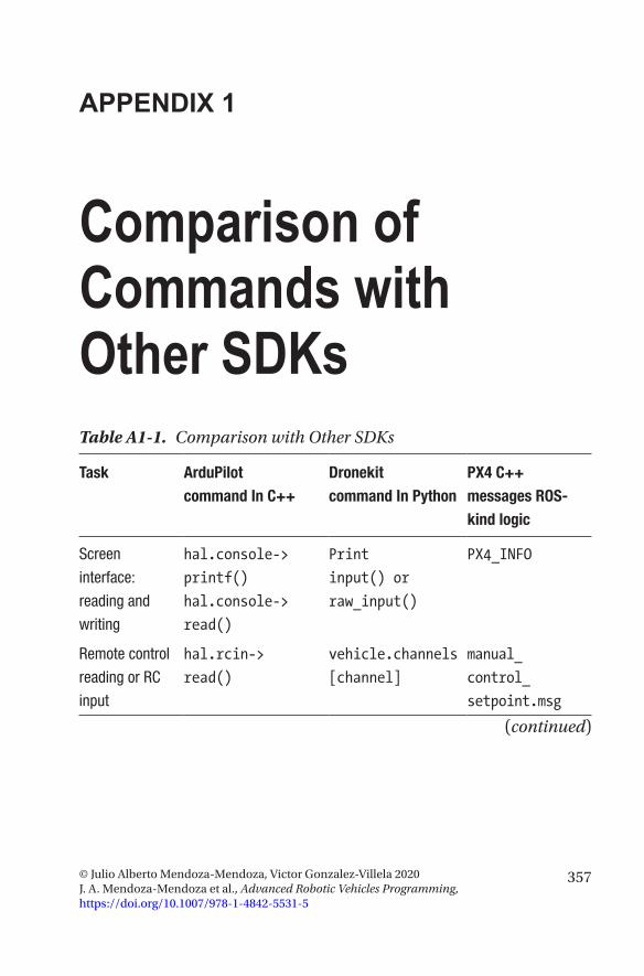
Comparison of Commands with Other SDKsTable A1-1. Comparison with Other SDKs
Task ArduPilot command In C++
Dronekit command In Python
PX4 C++ messages ROS-kind logic
Screen
interface:
reading and
writing
hal.console->
printf()
hal.console->
read()
input() or
raw_input()
PX4_INFO
Remote control
reading or RC
input
hal.rcin->
read()
vehicle.channels
[channel]
manual_
control_
setpoint.msg
(continued)
358
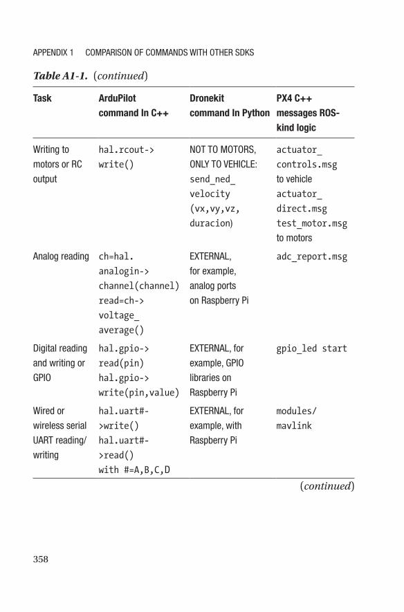
Task ArduPilot command In C++
Dronekit command In Python
PX4 C++ messages ROS-kind logic
Writing to
motors or RC
output
hal.rcout->
write()
NOT TO MOTORS,
ONLY TO VEHICLE:
send_ned_
velocity
(vx,vy,vz,
duracion)
actuator_
controls.msg
to vehicle
actuator_
direct.msg
test_motor.msg
to motors
Analog reading ch=hal.
analogin->
channel(channel)
read=ch->
voltage_
average()
EXTERNAL,
for example,
analog ports
on Raspberry Pi
adc_report.msg
Digital reading
and writing or
GPIO
hal.gpio->
read(pin)
hal.gpio->
write(pin,value)
EXTERNAL, for
example, GPIO
libraries on
Raspberry Pi
gpio_led start
Wired or
wireless serial
UART reading/
writing
hal.uart#-
>write()
hal.uart#-
>read()
with #=A,B,C,D
EXTERNAL, for
example, with
Raspberry Pi
modules/
mavlink
Table A1-1. (continued)
(continued)
APPENDIX 1 COMPARISON Of COMMANDS WITH OTHER SDKS
359
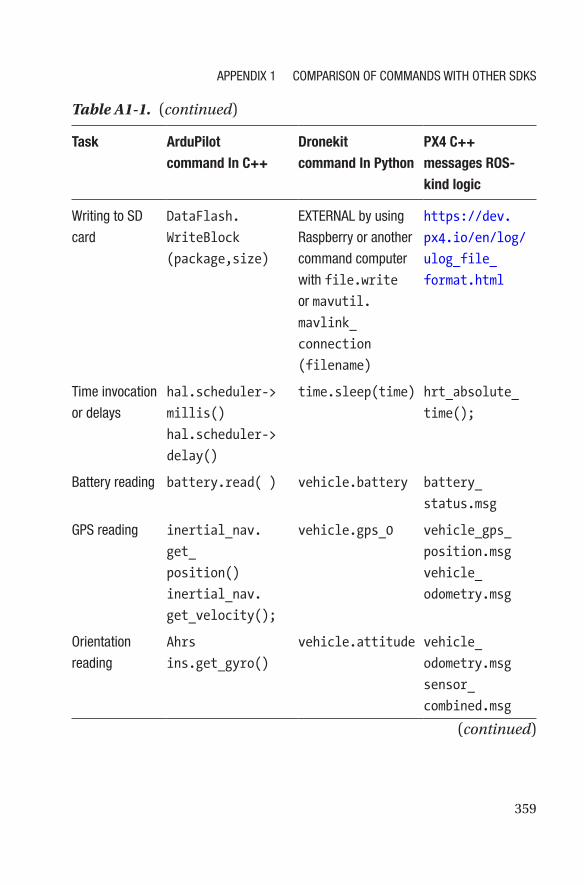
Task ArduPilot command In C++
Dronekit command In Python
PX4 C++ messages ROS-kind logic
Writing to SD
card
DataFlash.
WriteBlock
(package,size)
EXTERNAL by using
Raspberry or another
command computer
with file.write
or mavutil.
mavlink_
connection
(filename)
https://dev.
px4.io/en/log/
ulog_file_
format.html
Time invocation
or delays
hal.scheduler->
millis()
hal.scheduler->
delay()
time.sleep(time) hrt_absolute_
time();
Battery reading battery.read( ) vehicle.battery battery_
status.msg
GPS reading inertial_nav.
get_
position()
inertial_nav.
get_velocity();
vehicle.gps_0 vehicle_gps_
position.msg
vehicle_
odometry.msg
Orientation
reading
Ahrs
ins.get_gyro()
vehicle.attitude vehicle_
odometry.msg
sensor_
combined.msg
Table A1-1. (continued)
(continued)
APPENDIX 1 COMPARISON Of COMMANDS WITH OTHER SDKS
360
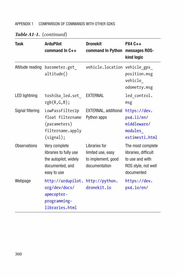
Task ArduPilot command In C++
Dronekit command In Python
PX4 C++ messages ROS-kind logic
Altitude reading barometer.get_
altitude()
vehicle.location vehicle_gps_
position.msg
vehicle_
odometry.msg
LED lightning toshiba_led.set_
rgb(R,G,B);
EXTERNAL led_control.
msg
Signal filtering LowPassFilter2p
float filtername
(parameters)
filtername.apply
(signal);
EXTERNAL, additional
Python apps
https://dev.
px4.ii/en/
middleware/
modules_
estimesti.html
Observations Very complete
libraries to fully use
the autopilot, widely
documented, and
easy to use
Libraries for
limited use, easy
to implement, good
documentation
The most complete
libraries, difficult
to use and with
ROS style, not well
documented
Webpage http://ardupilot.
org/dev/docs/
apmcopter-
programming-
libraries.html
http://python.
dronekit.io
https://dev.
px4.io/en/
Table A1-1. (continued)
APPENDIX 1 COMPARISON Of COMMANDS WITH OTHER SDKS
361© Julio Alberto Mendoza-Mendoza, Victor Gonzalez-Villela 2020 J. A. Mendoza-Mendoza et al., Advanced Robotic Vehicles Programming, https://doi.org/10.1007/978-1-4842-5531-5
APPENDIX 2
Setup Extended CodeThe following lines must be placed in each new program. It is advisable
not to omit any of them in order to avoid incurring errors due to omission
of data. In the best case, it is only advisable to add more lines of code as
needed or to encapsulate certain specific lines in a function, as previously
illustrated in the case of SD memory writing.
void setup()
{
ins.init(AP_InertialSensor::COLD_START,AP_InertialSensor::
RATE_400HZ);
serial_manager.init_console();
serial_manager.init();
compass.init();
compass.read();
ahrs.set_compass(&compass);
gps.init(NULL,serial_manager);
barometer.init();
barometer.calibrate();
DataFlash.Init(log_structure, sizeof(log_structure)/
sizeof(log_structure[0]));
if (DataFlash.NeedErase()) {
DataFlash.EraseAll();
}
362
log_num = DataFlash.StartNewLog();
hal.scheduler->delay(100);
}
As you can see, the basic setup consists of starting the serial console
(to at least send messages to a terminal), and then initializing the compass,
the inertial sensor, the GPS, the barometer, and the combined module
AHRS (so that the autopilot has a notion of its position and spatial
orientation), and finally the storage module to the SD card. This initializer
is the base mode and sometimes, as illustrated in the pertinent sections,
it will be necessary to add lines (for items such as motors, LEDs, batteries,
UART serial communication, and analog and digital ports).
Appendix 2 Setup extended Code
363© Julio Alberto Mendoza-Mendoza, Victor Gonzalez-Villela 2020 J. A. Mendoza-Mendoza et al., Advanced Robotic Vehicles Programming, https://doi.org/10.1007/978-1-4842-5531-5
APPENDIX 3
Extended HeaderThis header information must be placed in each code file so that the
programs can be executed.
The following header lines must be added to each new code file.
They contain the invocation of all the necessary functions of the ArduPilot
libraries. It is suggested to not modify them and in the best case, only add
the necessary library. Do not remove any line of code if you are not sure
about the library or command to be removed. Note that they have been
taken almost completely from the ardupilot.pde file. Just copy and paste
the following:
// place the header here //
// c libraries
#include <math.h>
#include <stdio.h>
#include <stdlib.h>
#include <stdarg.h>
// Common dependencies
#include <AP_Common.h>
#include <AP_Progmem.h>
#include <AP_Menu.h>
#include <AP_Param.h>
#include <StorageManager.h>
// AP_HAL
364
#include <AP_HAL.h>
#include <AP_HAL_AVR.h>
#include <AP_HAL_SITL.h>
#include <AP_HAL_PX4.h>
#include <AP_HAL_VRBRAIN.h>
#include <AP_HAL_FLYMAPLE.h>
#include <AP_HAL_Linux.h>
#include <AP_HAL_Empty.h>
#include <AP_Math.h>
// Application dependencies
#include <GCS.h>
#include <GCS_MAVLink.h> // MAVLink GCS definitions
#include <AP_SerialManager.h> // Serial manager library
#include <AP_GPS.h> // ArduPilot GPS library
#include <DataFlash.h> // ArduPilot Mega Flash Memory
// Library
#include <AP_ADC.h> // ArduPilot Mega Analog to
// Digital Converter Library
#include <AP_ADC_AnalogSource.h>
#include <AP_Baro.h>
#include <AP_Compass.h> // ArduPilot Mega Magnetometer
// Library
#include <AP_Math.h> // ArduPilot Mega Vector/Matrix
// math Library
#include <AP_Curve.h> // Curve used to linearlise
// throttle pwm to thrust
#include <AP_InertialSensor.h> // ArduPilot Mega Inertial
// Sensor (accel & gyro) Library
#include <AP_AHRS.h>
#include <AP_NavEKF.h>
#include <AP_Mission.h> // Mission command library
APPENDIX 3 EXtENDED HEADEr
365
#include <AP_Rally.h> // Rally point library
#include <AC_PID.h> // PID library
#include <AC_PI_2D.h> // PID library (2-axis)
#include <AC_HELI_PID.h> // Heli specific Rate PID
// library
#include <AC_P.h> // P library
#include <AC_AttitudeControl.h> // Attitude control library
#include <AC_AttitudeControl_Heli.h> // Attitude control
// library for traditional
// helicopter
#include <AC_PosControl.h> // Position control library
#include <RC_Channel.h> // RC Channel Library
#include <AP_Motors.h> // AP Motors library
#include <AP_RangeFinder.h> // Range finder library
#include <AP_OpticalFlow.h> // Optical Flow library
#include <Filter.h> // Filter library
#include <AP_Buffer.h> // APM FIFO Buffer
#include <AP_Relay.h> // APM relay
#include <AP_ServoRelayEvents.h>
#include <AP_Camera.h> // Photo or video camera
#include <AP_Mount.h> // Camera/Antenna mount
#include <AP_Airspeed.h> // needed for AHRS build
#include <AP_Vehicle.h> // needed for AHRS build
#include <AP_InertialNav.h> // ArduPilot Mega inertial
// navigation library
#include <AC_WPNav.h> // ArduCopter waypoint
// navigation library
#include <AC_Circle.h> // circle navigation library
#include <AP_Declination.h> // ArduPilot Mega Declination
// Helper Library
#include <AC_Fence.h> // Arducopter Fence library
#include <SITL.h> // software in the loop support
APPENDIX 3 EXtENDED HEADEr
366
#include <AP_Scheduler.h> // main loop scheduler
#include <AP_RCMapper.h> // RC input mapping library
#include <AP_Notify.h> // Notify library
#include <AP_BattMonitor.h> // Battery monitor library
#include <AP_BoardConfig.h> // board configuration library
#include <AP_Frsky_Telem.h>
#if SPRAYER == ENABLED
#include <AC_Sprayer.h> // crop sprayer library
#endif
#if EPM_ENABLED == ENABLED
#include <AP_EPM.h> // EPM cargo gripper stuff
#endif
#if PARACHUTE == ENABLED
#include <AP_Parachute.h> // Parachute release library
#endif
#include <AP_LandingGear.h> // Landing Gear library
#include <AP_Terrain.h>
#include <LowPassFilter2p.h>
// AP_HAL to Arduino compatibility layer
#include "compat.h"
// Configuration
#include "defines.h"
#include "config.h"
#include "config_channels.h"
// lines referring to the times of the pixhawk autopilot, which
// works at 400mhz or 0.0025seconds or 2500 microseconds
# define MAIN_LOOP_RATE 400
# define MAIN_LOOP_SECONDS 0.0025f
# define MAIN_LOOP_MICROS 2500
APPENDIX 3 EXtENDED HEADEr
367
// statements referring to the autopilot objects, for example,
// gps-type objects barometer, compass, DataFlash, etc., all of
// them will subsequently be invoked in the corresponding code
const AP_HAL::HAL& hal = AP_HAL_BOARD_DRIVER;
static AP_Scheduler scheduler;
static AP_GPS gps;
static AP_Baro barometer;
static AP_InertialSensor ins;
static RangeFinder sonar;
static Compass compass;
static AP_SerialManager serial_manager;
static ToshibaLED_PX4 toshiba_led;
static AP_BattMonitor battery;
//Data, BE CAREFUL, WHEN YOU READ THE SD SECTION DELETE THIS
//BLOCK THERE
// you will learn how to use and external module and deep
// details about these declarations
#define LOG_MSG 0x01
#if CONFIG_HAL_BOARD == HAL_BOARD_PX4
static DataFlash_File DataFlash("/fs/microsd/APM/LOGS");
#endif
struct PACKED log_Datos{
LOG_PACKET_HEADER;
uint32_t time_ms;
float a_roll;
float a_pitch;
float a_yaw;
APPENDIX 3 EXtENDED HEADEr
368
float pos_x;
float pos_y;
float pos_z;
};
static const struct LogStructure log_structure[] PROGMEM = {
LOG_COMMON_STRUCTURES,
{LOG_MSG, sizeof(log_Datos),
"1", "Iffffff", "T_MS,ROLL,PITCH,YAW,X_POS,Y_POS,Z_
POS"},
};
static uint16_t log_num; //Dataflash
// Inertial Navigation EKF
#if AP_AHRS_NAVEKF_AVAILABLE
AP_AHRS_NavEKF ahrs(ins, barometer, gps, sonar);
#else
AP_AHRS_DCM ahrs(ins, barometer, gps);
#endif
static AP_InertialNav_NavEKF inertial_nav(ahrs);
// place your code here //
Previously an abbreviated description of these libraries was made. For
a more complete reference, consult the following documentation:
Alejandro Romero Galan, “Revision y modificacion del firmware
de libre acceso arducopter para su uso en el proyecto airwhale,” Thesis,
Universidad de Sevilla, 2015 (in Spanish).
http://ardupilot.org/dev/docs/apmcopter-programming-
libraries.html
https://github.com/ArduPilot/ardupilot/tree/master/libraries
APPENDIX 3 EXtENDED HEADEr
369© Julio Alberto Mendoza-Mendoza, Victor Gonzalez-Villela 2020 J. A. Mendoza-Mendoza et al., Advanced Robotic Vehicles Programming, https://doi.org/10.1007/978-1-4842-5531-5
APPENDIX 4
The Fully Functional CodeHere is the complete code, including the header and setup information:
// paste the header here //
// c libraries
#include <math.h>
#include <stdio.h>
#include <stdlib.h>
#include <stdarg.h>
// Common dependencies
#include <AP_Common.h>
#include <AP_Progmem.h>
#include <AP_Menu.h>
#include <AP_Param.h>
#include <StorageManager.h>
// AP_HAL
#include <AP_HAL.h>
#include <AP_HAL_AVR.h>
#include <AP_HAL_SITL.h>
#include <AP_HAL_PX4.h>
#include <AP_HAL_VRBRAIN.h>
370
#include <AP_HAL_FLYMAPLE.h>
#include <AP_HAL_Linux.h>
#include <AP_HAL_Empty.h>
#include <AP_Math.h>
// Application dependencies
#include <GCS.h>
#include <GCS_MAVLink.h> // MAVLink GCS definitions
#include <AP_SerialManager.h> // Serial manager library
#include <AP_GPS.h> // ArduPilot GPS library
#include <DataFlash.h> // ArduPilot Mega Flash Memory
// Library
#include <AP_ADC.h> // ArduPilot Mega Analog to
// Digital Converter Library
#include <AP_ADC_AnalogSource.h>
#include <AP_Baro.h>
#include <AP_Compass.h> // ArduPilot Mega Magnetometer
// Library
#include <AP_Math.h> // ArduPilot Mega Vector/Matrix
// math Library
#include <AP_Curve.h> // Curve used to linearlise
// throttle pwm to thrust
#include <AP_InertialSensor.h> // ArduPilot Mega Inertial
// Sensor (accel & gyro) Library
#include <AP_AHRS.h>
#include <AP_NavEKF.h>
#include <AP_Mission.h> // Mission command library
#include <AP_Rally.h> // Rally point library
#include <AC_PID.h> // PID library
#include <AC_PI_2D.h> // PID library (2-axis)
#include <AC_HELI_PID.h> // Heli specific Rate PID
// library
APPENDIX 4 ThE Fully FuNcTIoNAl coDE
371
#include <AC_P.h> // P library
#include <AC_AttitudeControl.h> // Attitude control library
#include <AC_AttitudeControl_Heli.h> // Attitude control
// library for traditional
// helicopter
#include <AC_PosControl.h> // Position control library
#include <RC_Channel.h> // RC Channel Library
#include <AP_Motors.h> // AP Motors library
#include <AP_RangeFinder.h> // Range finder library
#include <AP_OpticalFlow.h> // Optical Flow library
#include <Filter.h> // Filter library
#include <AP_Buffer.h> // APM FIFO Buffer
#include <AP_Relay.h> // APM relay
#include <AP_ServoRelayEvents.h>
#include <AP_Camera.h> // Photo or video camera
#include <AP_Mount.h> // Camera/Antenna mount
#include <AP_Airspeed.h> // needed for AHRS build
#include <AP_Vehicle.h> // needed for AHRS build
#include <AP_InertialNav.h> // ArduPilot Mega inertial
// navigation library
#include <AC_WPNav.h> // ArduCopter waypoint
// navigation library
#include <AC_Circle.h> // circle navigation library
#include <AP_Declination.h> // ArduPilot Mega Declination
// Helper Library
#include <AC_Fence.h> // Arducopter Fence library
#include <SITL.h> // software in the loop support
#include <AP_Scheduler.h> // main loop scheduler
#include <AP_RCMapper.h> // RC input mapping library
#include <AP_Notify.h> // Notify library
#include <AP_BattMonitor.h> // Battery monitor library
#include <AP_BoardConfig.h> // board configuration library
APPENDIX 4 ThE Fully FuNcTIoNAl coDE
372
#include <AP_Frsky_Telem.h>
#if SPRAYER == ENABLED
#include <AC_Sprayer.h> // crop sprayer library
#endif
#if EPM_ENABLED == ENABLED
#include <AP_EPM.h> // EPM cargo gripper stuff
#endif
#if PARACHUTE == ENABLED
#include <AP_Parachute.h> // Parachute release library
#endif
#include <AP_LandingGear.h> // Landing Gear library
#include <AP_Terrain.h>
#include <LowPassFilter2p.h>
// AP_HAL to Arduino compatibility layer
#include "compat.h"
// Configuration
#include "defines.h"
#include "config.h"
#include "config_channels.h"
// lines referring to the times of the pixhawk autopilot, which
// works at 400mhz or 0.0025seconds or 2500 microseconds
# define MAIN_LOOP_RATE 400
# define MAIN_LOOP_SECONDS 0.0025f
# define MAIN_LOOP_MICROS 2500
// statements referring to the autopilot objects, for example,
// gps-type objects barometer, compass, DataFlash, etc., all of
// them will subsequently be invoked in the corresponding code
APPENDIX 4 ThE Fully FuNcTIoNAl coDE
373
const AP_HAL::HAL& hal = AP_HAL_BOARD_DRIVER;
static AP_Scheduler scheduler;
static AP_GPS gps;
static AP_Baro barometer;
static AP_InertialSensor ins;
static RangeFinder sonar;
static Compass compass;
static AP_SerialManager serial_manager;
static ToshibaLED_PX4 toshiba_led;
static AP_BattMonitor battery;
//Data, BE CAREFUL, WHEN YOU READ THE SD SECTION DELETE THIS
//BLOCK THERE
// you will learn how to use and external module and deep
// details about these declarations
#define LOG_MSG 0x01
#if CONFIG_HAL_BOARD == HAL_BOARD_PX4
static DataFlash_File DataFlash("/fs/microsd/APM/LOGS");
#endif
struct PACKED log_Datos{
LOG_PACKET_HEADER;
uint32_t time_ms;
float a_roll;
float a_pitch;
float a_yaw;
float pos_x;
float pos_y;
float pos_z;
};
APPENDIX 4 ThE Fully FuNcTIoNAl coDE
374
static const struct LogStructure log_structure[] PROGMEM = {
LOG_COMMON_STRUCTURES,
{LOG_MSG, sizeof(log_Datos),
"1", "Iffffff", "T_MS,ROLL,PITCH,YAW,X_POS,Y_POS,
Z_POS"},
};
static uint16_t log_num; //Dataflash
// Inertial Navigation EKF
#if AP_AHRS_NAVEKF_AVAILABLE
AP_AHRS_NavEKF ahrs(ins, barometer, gps, sonar);
#else
AP_AHRS_DCM ahrs(ins, barometer, gps);
#endif
static AP_InertialNav_NavEKF inertial_nav(ahrs);
// place your code here //
// paste the setup here //
void setup()
{
ins.init(AP_InertialSensor::COLD_START,AP_InertialSensor::
RATE_400HZ);
serial_manager.init_console();
serial_manager.init();
compass.init();
compass.read();
ahrs.set_compass(&compass);
gps.init(NULL,serial_manager);
barometer.init();
barometer.calibrate();
APPENDIX 4 ThE Fully FuNcTIoNAl coDE
375
DataFlash.Init(log_structure, sizeof(log_structure)/
sizeof(log_structure[0]));
if (DataFlash.NeedErase()) {
DataFlash.EraseAll();
}
log_num = DataFlash.StartNewLog();
hal.scheduler->delay(100);
}
void loop(void)
{
hal.console->printf("Hello %d\n",hal.scheduler->micros());
hal.scheduler->delay(50);
}
AP_HAL_MAIN();
APPENDIX 4 ThE Fully FuNcTIoNAl coDE
377© Julio Alberto Mendoza-Mendoza, Victor Gonzalez-Villela 2020 J. A. Mendoza-Mendoza et al., Advanced Robotic Vehicles Programming, https://doi.org/10.1007/978-1-4842-5531-5
APPENDIX 5
Helpful KeywordsThe following is a list of thematic keywords. Feel free to use them in order
to search for more information in your web browser.
• Quadrotor, quadcopter, aircraft
• Hover-altitude, attitude-orientation, steering
• Real time, OOP, modular programming, scheduler
• Euler angles, roll, pitch, yaw, quasi-velocities
• Linear systems, linearization, non-linear systems
• Autopilot, companion computer/development board
• SDK/software development kit, GUI/graphic user
interface
• Data types
• PWM/pulse width modulation, PPM/pulse position
modulation, RC
• Duty cycle
• BLDC/brushless DC, BDC/brushed DC, DC
• ESC/electronic speed control, BEC/battery elimination
circuit, power module
378
• Propeller, frame
• Checksum, buffer, GPIO/general purpose input output
• Allocation matrix, thrust vectoring, tethered drone
APPENDIX 5 HElPful KEyworDs
379© Julio Alberto Mendoza-Mendoza, Victor Gonzalez-Villela 2020 J. A. Mendoza-Mendoza et al., Advanced Robotic Vehicles Programming, https://doi.org/10.1007/978-1-4842-5531-5
APPENDIX 6
Installing ArduPilot LibrariesThere are various ways to install the libraries depending on the operating
system, the computer platform, and the code editor used. However, this
appendix presents a brief installation description based on Windows 7,
Vista, and 10 32/64-bit operating systems using the preloaded Eclipse
interface (if this interface is already available on your computer, additional
changes may be necessary).
Since we are working with open source technologies, it is very common
to deal with changes without prior notice, which may even affect the
installation mode. Although a set of all the necessary programs is provided
with this book (all of them are open source and free), it is advisable to be
aware of the important changes if you want to update versions. You should
also visit the corresponding forums.
We remind you that the maximum scope of this book is to disseminate
knowledge related to these technologies and it is not intended to go
beyond any personal project. Any doubt in this regard, refer to web forums.
“Generic” Procedure
1. Install the driver.
2. Download the libraries.
380
3. Download the compiler.
4. Compile the libraries.
5. Customize the code editing interface.
6. Program custom code.
7. Compile and test it.
Installation requirements: Windows Vista or superior operating
system at 32- or 64-bit, 4GB of RAM for the execution of the development
interface, and USB 2.0 ports for using the Pixhawk.
Installation Procedure
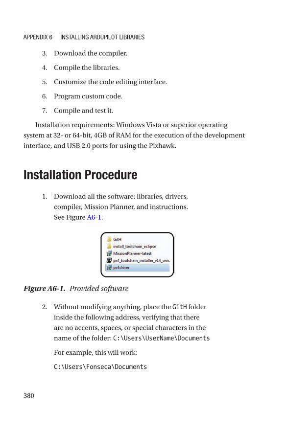
1. Download all the software: libraries, drivers,
compiler, Mission Planner, and instructions.
See Figure A6-1.
2. Without modifying anything, place the GitH folder
inside the following address, verifying that there
are no accents, spaces, or special characters in the
name of the folder: C:\Users\UserName\Documents
For example, this will work:
C:\Users\Fonseca\Documents
Figure A6-1. Provided software
APPENDIX 6 INstAllINg ArDuPIlot lIbrArIEs
381
And this will not work because of the accent:
C:\Users\León\Documents
3. Once the GitH folder has been copied, make sure
that the directory’s name is made up of 50 characters
counting from “C:” to the “ardupilot” folder.
For example, this will work because it has 41
characters:
C:\Users\Fonseca\Documents\GitH\ardupilot
And this will not work because it has 51:
C:\Users\FonsecaMendezMend\Documents\GitH\
ardupilot
To make it functional, it is possible to reduce the
GitHub folder’s name (it is only possible to modify
this folder; altering the others will affect the user’s
computer):
C:\Users\FonsecaMendezMend\Documents\Gi\
ardupilot
Now it has 49 characters and therefore it is useful.
Note that if you have more than 50 characters or
spaces, or if you have accents or symbols, you can still
install these libraries by creating a new administrator
user account which will comply with the above
requirements. Before this, you must ensure that you
have removed all of the installation folders from your
actual user account.
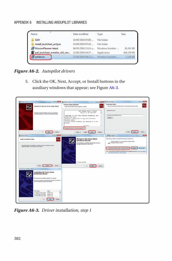
4. Install the Pixhawk drivers; see Figure A6-2.
APPENDIX 6 INstAllINg ArDuPIlot lIbrArIEs
382
5. Click the OK, Next, Accept, or Install buttons in the
auxiliary windows that appear; see Figure A6-3.
Figure A6-2. Autopilot drivers
Figure A6-3. Driver installation, step 1
APPENDIX 6 INstAllINg ArDuPIlot lIbrArIEs
383
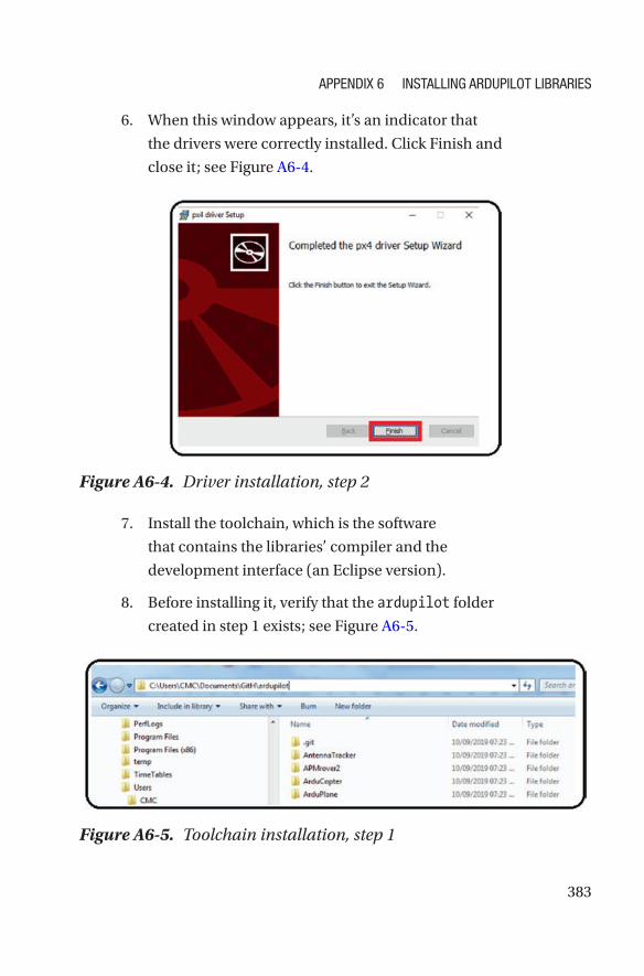
6. When this window appears, it’s an indicator that
the drivers were correctly installed. Click Finish and
close it; see Figure A6-4.
7. Install the toolchain, which is the software
that contains the libraries’ compiler and the
development interface (an Eclipse version).
8. Before installing it, verify that the ardupilot folder
created in step 1 exists; see Figure A6-5.
Figure A6-4. Driver installation, step 2
Figure A6-5. Toolchain installation, step 1
APPENDIX 6 INstAllINg ArDuPIlot lIbrArIEs
384
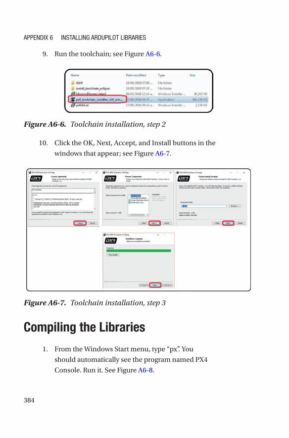
9. Run the toolchain; see Figure A6-6.
10. Click the OK, Next, Accept, and Install buttons in the
windows that appear; see Figure A6-7.
Compiling the Libraries
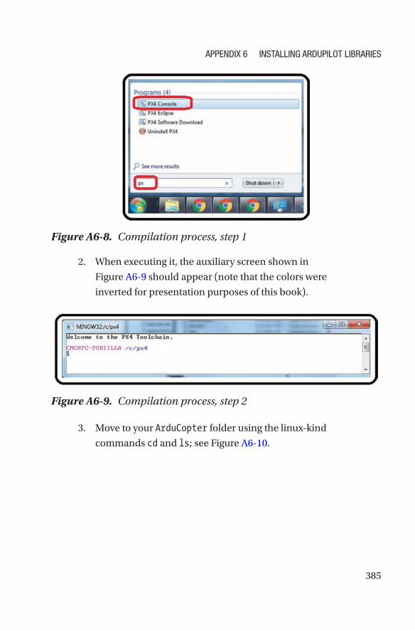
1. From the Windows Start menu, type “px”. You
should automatically see the program named PX4
Console. Run it. See Figure A6-8.
Figure A6-6. Toolchain installation, step 2
Figure A6-7. Toolchain installation, step 3
APPENDIX 6 INstAllINg ArDuPIlot lIbrArIEs
385
2. When executing it, the auxiliary screen shown in
Figure A6-9 should appear (note that the colors were
inverted for presentation purposes of this book).
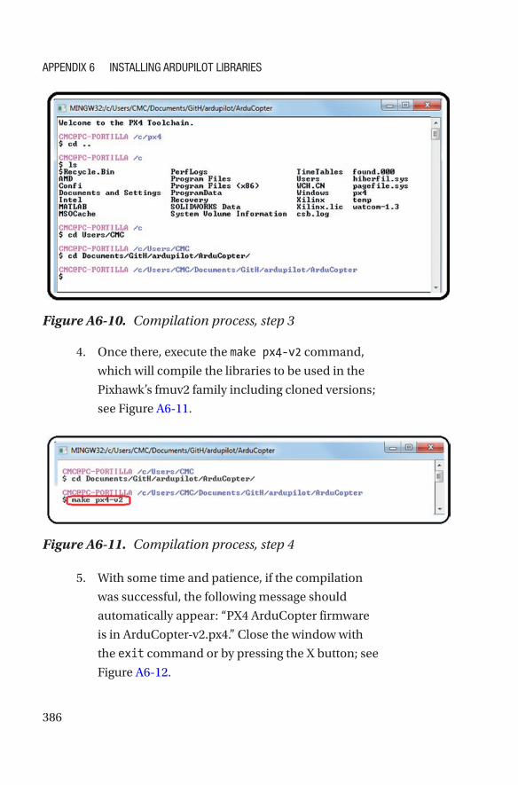
3. Move to your ArduCopter folder using the linux-kind
commands cd and ls; see Figure A6-10.
Figure A6-8. Compilation process, step 1
Figure A6-9. Compilation process, step 2
APPENDIX 6 INstAllINg ArDuPIlot lIbrArIEs
386
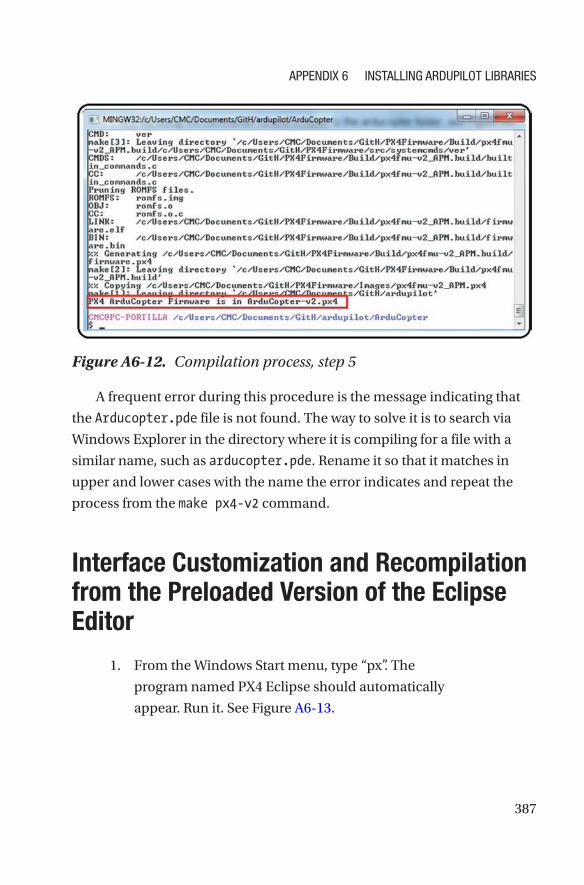
4. Once there, execute the make px4-v2 command,
which will compile the libraries to be used in the
Pixhawk’s fmuv2 family including cloned versions;
see Figure A6-11.
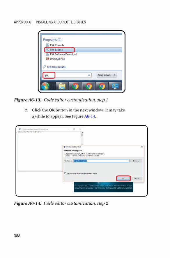
5. With some time and patience, if the compilation
was successful, the following message should
automatically appear: “PX4 ArduCopter firmware
is in ArduCopter-v2.px4.” Close the window with
the exit command or by pressing the X button; see
Figure A6-12.
Figure A6-10. Compilation process, step 3
Figure A6-11. Compilation process, step 4
APPENDIX 6 INstAllINg ArDuPIlot lIbrArIEs
387
A frequent error during this procedure is the message indicating that
the Arducopter.pde file is not found. The way to solve it is to search via
Windows Explorer in the directory where it is compiling for a file with a
similar name, such as arducopter.pde. Rename it so that it matches in
upper and lower cases with the name the error indicates and repeat the
process from the make px4-v2 command.
Interface Customization and Recompilation from the Preloaded Version of the Eclipse Editor
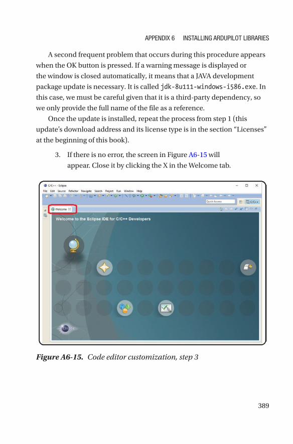
1. From the Windows Start menu, type “px”. The
program named PX4 Eclipse should automatically
appear. Run it. See Figure A6-13.
Figure A6-12. Compilation process, step 5
APPENDIX 6 INstAllINg ArDuPIlot lIbrArIEs
388
2. Click the OK button in the next window. It may take
a while to appear. See Figure A6-14.
Figure A6-13. Code editor customization, step 1
Figure A6-14. Code editor customization, step 2
APPENDIX 6 INstAllINg ArDuPIlot lIbrArIEs
389
A second frequent problem that occurs during this procedure appears
when the OK button is pressed. If a warning message is displayed or
the window is closed automatically, it means that a JAVA development
package update is necessary. It is called jdk-8u111-windows-i586.exe. In
this case, we must be careful given that it is a third-party dependency, so
we only provide the full name of the file as a reference.
Once the update is installed, repeat the process from step 1 (this
update’s download address and its license type is in the section “Licenses”
at the beginning of this book).
3. If there is no error, the screen in Figure A6-15 will
appear. Close it by clicking the X in the Welcome tab.
Figure A6-15. Code editor customization, step 3
APPENDIX 6 INstAllINg ArDuPIlot lIbrArIEs
390
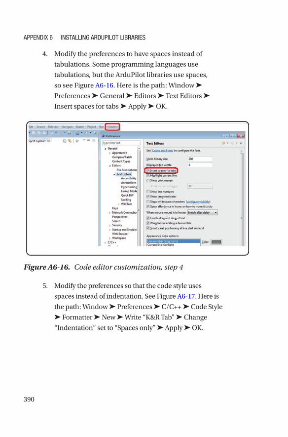
4. Modify the preferences to have spaces instead of
tabulations. Some programming languages use
tabulations, but the ArduPilot libraries use spaces,
so see Figure A6-16. Here is the path: Window ➤
Preferences ➤ General ➤ Editors ➤ Text Editors ➤
Insert spaces for tabs ➤ Apply ➤ OK.
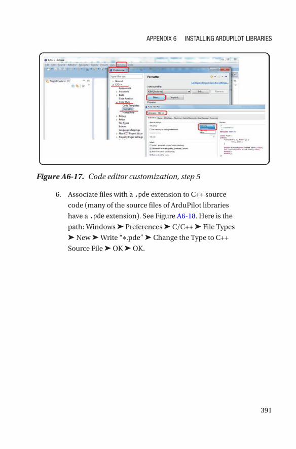
5. Modify the preferences so that the code style uses
spaces instead of indentation. See Figure A6-17. Here is
the path: Window ➤ Preferences ➤ C/C++ ➤ Code Style
➤ Formatter ➤ New ➤ Write “K&R Tab” ➤ Change
“Indentation” set to “Spaces only” ➤ Apply ➤ OK.
Figure A6-16. Code editor customization, step 4
APPENDIX 6 INstAllINg ArDuPIlot lIbrArIEs
391
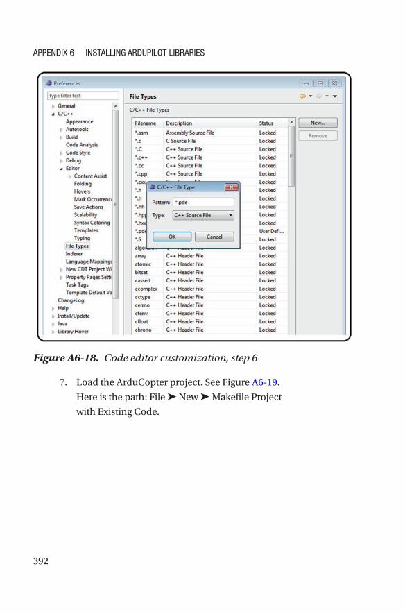
6. Associate files with a .pde extension to C++ source
code (many of the source files of ArduPilot libraries
have a .pde extension). See Figure A6-18. Here is the
path: Windows ➤ Preferences ➤ C/C++ ➤ File Types
➤ New ➤ Write “∗.pde” ➤ Change the Type to C++
Source File ➤ OK ➤ OK.
Figure A6-17. Code editor customization, step 5
APPENDIX 6 INstAllINg ArDuPIlot lIbrArIEs
392
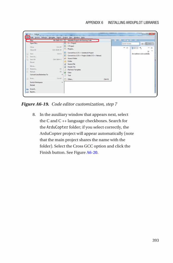
7. Load the ArduCopter project. See Figure A6-19.
Here is the path: File ➤ New ➤ Makefile Project
with Existing Code.
Figure A6-18. Code editor customization, step 6
APPENDIX 6 INstAllINg ArDuPIlot lIbrArIEs
393
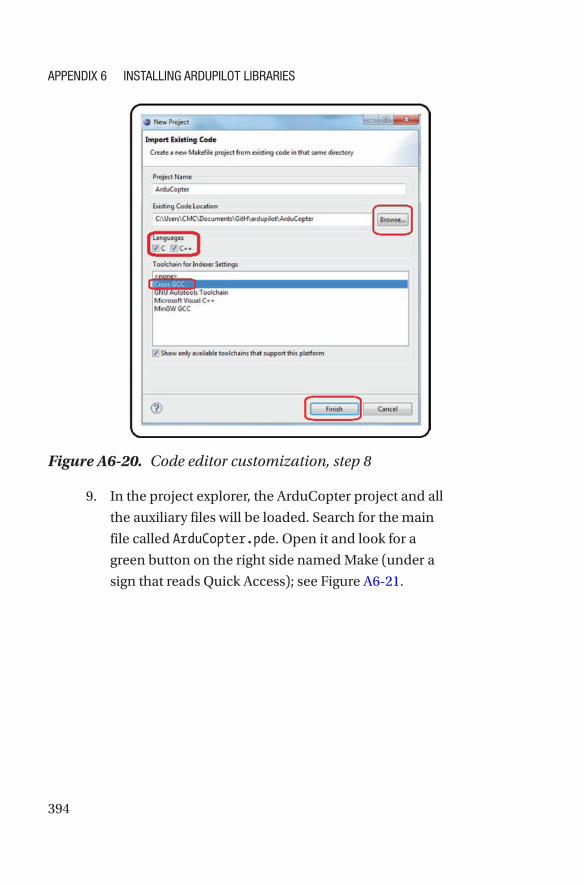
8. In the auxiliary window that appears next, select
the C and C ++ language checkboxes. Search for
the ArduCopter folder; if you select correctly, the
ArduCopter project will appear automatically (note
that the main project shares the name with the
folder). Select the Cross GCC option and click the
Finish button. See Figure A6-20.
Figure A6-19. Code editor customization, step 7
APPENDIX 6 INstAllINg ArDuPIlot lIbrArIEs
394
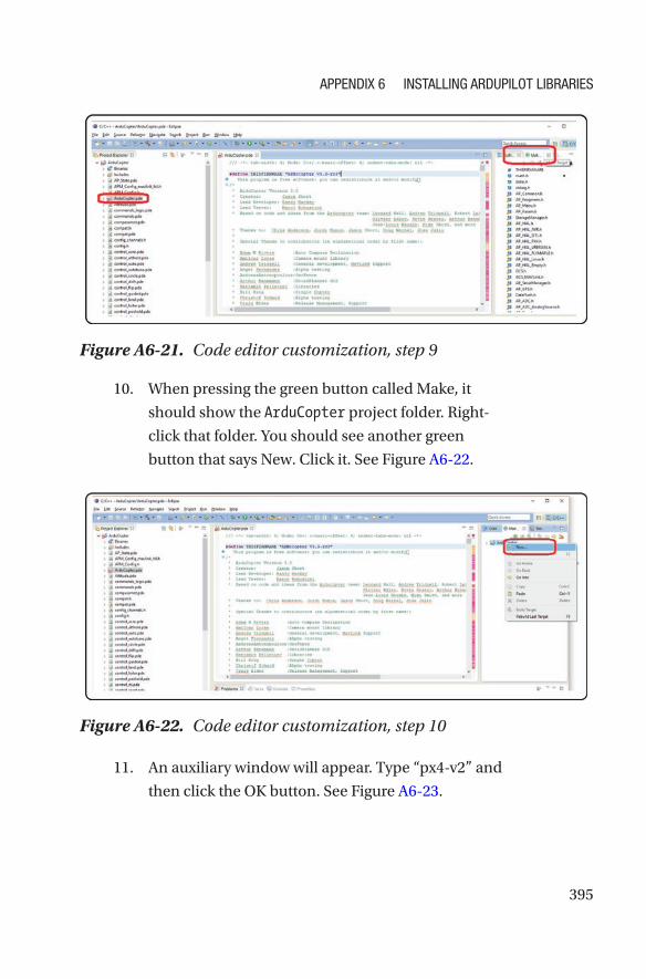
9. In the project explorer, the ArduCopter project and all
the auxiliary files will be loaded. Search for the main
file called ArduCopter.pde. Open it and look for a
green button on the right side named Make (under a
sign that reads Quick Access); see Figure A6-21.
Figure A6-20. Code editor customization, step 8
APPENDIX 6 INstAllINg ArDuPIlot lIbrArIEs
395
10. When pressing the green button called Make, it
should show the ArduCopter project folder. Right-
click that folder. You should see another green
button that says New. Click it. See Figure A6-22.
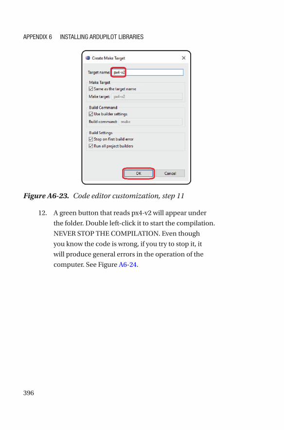
11. An auxiliary window will appear. Type “px4-v2” and
then click the OK button. See Figure A6-23.
Figure A6-21. Code editor customization, step 9
Figure A6-22. Code editor customization, step 10
APPENDIX 6 INstAllINg ArDuPIlot lIbrArIEs
396
12. A green button that reads px4-v2 will appear under
the folder. Double left-click it to start the compilation.
NEVER STOP THE COMPILATION. Even though
you know the code is wrong, if you try to stop it, it
will produce general errors in the operation of the
computer. See Figure A6-24.
Figure A6-23. Code editor customization, step 11
APPENDIX 6 INstAllINg ArDuPIlot lIbrArIEs
397
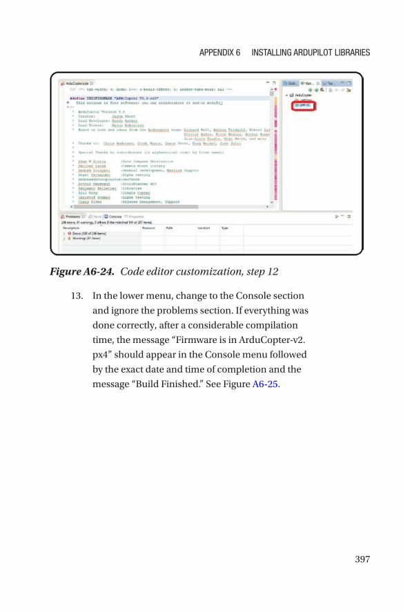
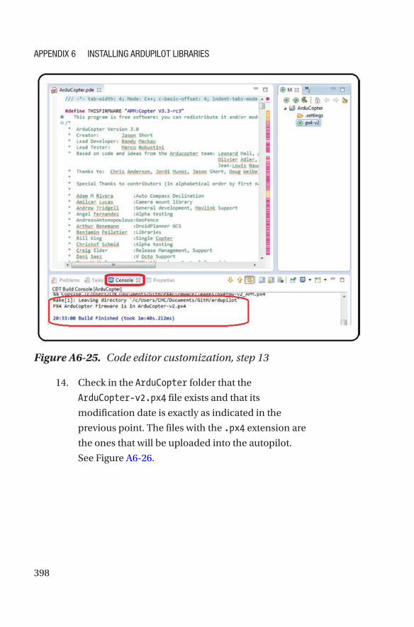
13. In the lower menu, change to the Console section
and ignore the problems section. If everything was
done correctly, after a considerable compilation
time, the message “Firmware is in ArduCopter-v2.
px4” should appear in the Console menu followed
by the exact date and time of completion and the
message “Build Finished.” See Figure A6-25.
Figure A6-24. Code editor customization, step 12
APPENDIX 6 INstAllINg ArDuPIlot lIbrArIEs
398
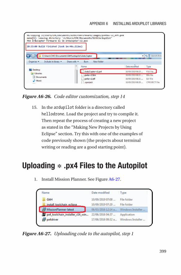
14. Check in the ArduCopter folder that the
ArduCopter-v2.px4 file exists and that its
modification date is exactly as indicated in the
previous point. The files with the .px4 extension are
the ones that will be uploaded into the autopilot.
See Figure A6-26.
Figure A6-25. Code editor customization, step 13
APPENDIX 6 INstAllINg ArDuPIlot lIbrArIEs
399
15. In the ardupilot folder is a directory called
hellodrone. Load the project and try to compile it.
Then repeat the process of creating a new project
as stated in the “Making New Projects by Using
Eclipse” section. Try this with one of the examples of
code previously shown (the projects about terminal
writing or reading are a good starting point).
Uploading ∗ .px4 Files to the Autopilot
1. Install Mission Planner. See Figure A6-27.
Figure A6-27. Uploading code to the autopilot, step 1
Figure A6-26. Code editor customization, step 14
APPENDIX 6 INstAllINg ArDuPIlot lIbrArIEs
400
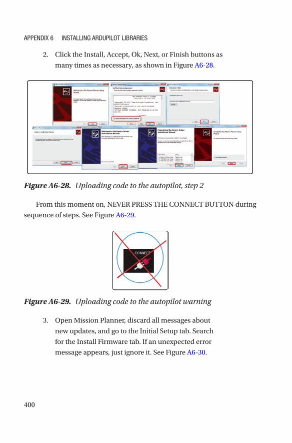
2. Click the Install, Accept, Ok, Next, or Finish buttons as
many times as necessary, as shown in Figure A6-28.
From this moment on, NEVER PRESS THE CONNECT BUTTON during
sequence of steps. See Figure A6-29.
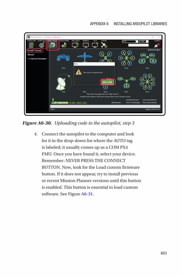
3. Open Mission Planner, discard all messages about
new updates, and go to the Initial Setup tab. Search
for the Install Firmware tab. If an unexpected error
message appears, just ignore it. See Figure A6-30.
Figure A6-29. Uploading code to the autopilot warning
Figure A6-28. Uploading code to the autopilot, step 2
APPENDIX 6 INstAllINg ArDuPIlot lIbrArIEs
401
4. Connect the autopilot to the computer and look
for it in the drop-down list where the AUTO tag
is labeled; it usually comes up as a COM PX4
FMU. Once you have found it, select your device.
Remember: NEVER PRESS THE CONNECT
BUTTON. Now, look for the Load custom firmware
button. If it does not appear, try to install previous
or recent Mission Planner versions until this button
is enabled. This button is essential to load custom
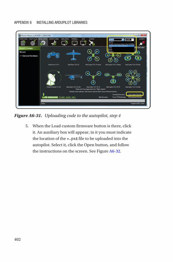
software. See Figure A6-31.
Figure A6-30. Uploading code to the autopilot, step 3
APPENDIX 6 INstAllINg ArDuPIlot lIbrArIEs
402
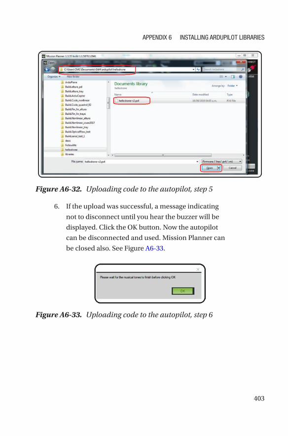
5. When the Load custom firmware button is there, click
it. An auxiliary box will appear; in it you must indicate
the location of the *.px4 file to be uploaded into the
autopilot. Select it, click the Open button, and follow
the instructions on the screen. See Figure A6-32.
Figure A6-31. Uploading code to the autopilot, step 4
APPENDIX 6 INstAllINg ArDuPIlot lIbrArIEs
403
6. If the upload was successful, a message indicating
not to disconnect until you hear the buzzer will be
displayed. Click the OK button. Now the autopilot
can be disconnected and used. Mission Planner can
be closed also. See Figure A6-33.
Figure A6-32. Uploading code to the autopilot, step 5
Figure A6-33. Uploading code to the autopilot, step 6
APPENDIX 6 INstAllINg ArDuPIlot lIbrArIEs
404
Terminal Test of the Previously Loaded Program
1. Reconnect the Pixhawk, remembering the address
assigned in step 4 above. If you don’t know this
address, look for it in devices and printers, or in the
Windows device manager.
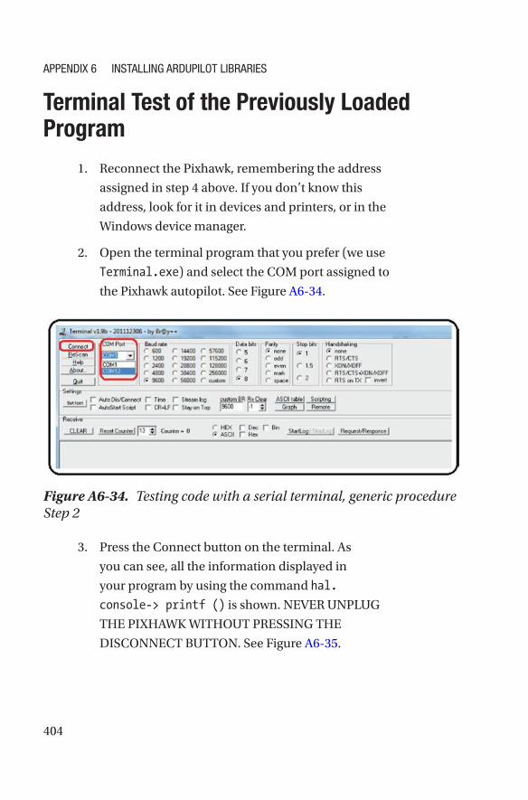
2. Open the terminal program that you prefer (we use
Terminal.exe) and select the COM port assigned to
the Pixhawk autopilot. See Figure A6- 34.
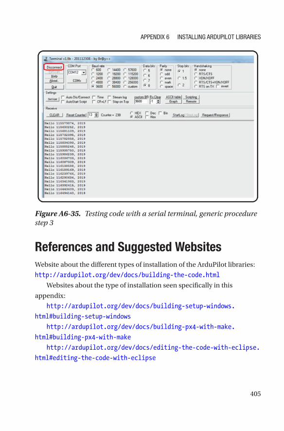
3. Press the Connect button on the terminal. As
you can see, all the information displayed in
your program by using the command hal.
console-> printf () is shown. NEVER UNPLUG
THE PIXHAWK WITHOUT PRESSING THE
DISCONNECT BUTTON. See Figure A6-35.
Figure A6-34. Testing code with a serial terminal, generic procedure Step 2
APPENDIX 6 INstAllINg ArDuPIlot lIbrArIEs
405
References and Suggested WebsitesWebsite about the different types of installation of the ArduPilot libraries:
http://ardupilot.org/dev/docs/building-the-code.html
Websites about the type of installation seen specifically in this
appendix:
http://ardupilot.org/dev/docs/building-setup-windows.
html#building- setup- windows
http://ardupilot.org/dev/docs/building-px4-with-make.
html#building- px4- with-make
http://ardupilot.org/dev/docs/editing-the-code-with-eclipse.
html#editing-the-code-with-eclipse
Figure A6-35. Testing code with a serial terminal, generic procedure step 3
APPENDIX 6 INstAllINg ArDuPIlot lIbrArIEs
407© Julio Alberto Mendoza-Mendoza, Victor Gonzalez-Villela 2020 J. A. Mendoza-Mendoza et al., Advanced Robotic Vehicles Programming, https://doi.org/10.1007/978-1-4842-5531-5
APPENDIX 7
Thrust VectoringBy controlling each one of the vehicle engines including the auxiliary
servos, the ArduPilot libraries and Pixhawk autopilot become a team of
great features. One of these features is the feasibility of designing unusual
or non-existent systems. For this, two concepts are presented: thrust
vectoring and omnidirectionality.
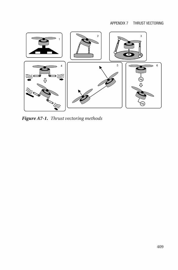
Thrust vectoring is the ability to regulate a motor’s main thrust
direction. This is achieved through several methods; see Figure A7-1.
1. With flaps: This method has been used for decades
by airplanes, ships, and cars. It uses one or more
fixed main engines, and flaps are used to deflect
the airflow (they are usually placed on the wings
or the tail). Once the main flow has been redirected,
the aircraft can change its flight direction.
2. With direct movement of the motor: This method
is feasible in toy airplanes since it involves directly
moving a full motor, which is already rotating at
high speeds, and moving an object that is rotating at
high speeds entails a lot of force by the servos that
move this engine (due to gyroscopic effects). It has
also been used in boats for several decades, where
the pilot moves a helm or rudder that deflects the
direction where the main engine pushes the boat.
408
3. With direct movement of the propeller’s blades:
This is a very useful method in large aircraft such as
helicopters. It allows deflecting the aircraft without
moving the main rotor—just by moving the blade’s
orientation by means of cyclic or collective plates or
swashplates.
4. With pneumatic and vacuum methods: This is
a similar idea to the use of flaps, but instead uses
tubes that blow air, liquid, or generate a vacuum to
divert the main airflow thrusted by the propellers.
5. With variations on the effect of multiple engines:
This is how quadcopter drones work. All engines
have a fixed position and direction of rotation in
a rigid body, and the movement of the body in
different directions is achieved by selectively varying
each engine’s speed.
6. With movement of a built-in mass: In this case, a
“massive” object placed in the vehicle’s center of
gravity is used. If a direction change is wanted, that
mass is moved, and the vehicle is forced to move in
the direction where this mass has been placed. This
example has been employed for decades with roller
skates, kayaks, and motorcycles, where the drivers,
in order to change vehicle’s direction, must tilt their
body toward the side where they want to move.
APPENDIX 7 ThrusT VEcTorINg
409
Figure A7-1. Thrust vectoring methods
APPENDIX 7 ThrusT VEcTorINg
411© Julio Alberto Mendoza-Mendoza, Victor Gonzalez-Villela 2020 J. A. Mendoza-Mendoza et al., Advanced Robotic Vehicles Programming, https://doi.org/10.1007/978-1-4842-5531-5
APPENDIX 8
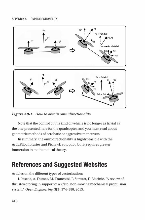
OmnidirectionalityIt is possible to introduce the concept of omnidirectionality by using one
of the vectorization methods previously explained. It basically provides
a vehicle with total mobility or the ability to achieve the reached position
regardless of orientation.
For example, a standard quadcopter cannot tilt and stay floating at
the same time because when it tilts, it tends to move in the direction it has
been tilted.
But if a standard quadcopter (or underwater vehicle) is fitted with extra
motors different to its planar configuration (like individual vectorizers for
each motor), you can get a system that floats at any point in space with
variable and independent orientation (maybe full movement, maybe
restricted). See Figure A8-1.
412
Figure A8-1. How to obtain omnidirectionality
Note that the control of this kind of vehicle is no longer as trivial as
the one presented here for the quadcopter, and you must read about
geometric methods of acrobatic or aggressive maneuvers.
In summary, the omnidirectionality is highly feasible with the
ArduPilot libraries and Pixhawk autopilot, but it requires greater
immersion in mathematical theory.
References and Suggested WebsitesArticles on the different types of vectorization:
J. Pascoa, A. Dumas, M. Trancossi, P. Stewart, D. Vucinic. “A review of
thrust-vectoring in support of a v/stol non-moving mechanical propulsion
system.” Open Engineering, 3(3):374–388, 2013.
APPENDIX 8 OmNIDIrEctIONAlIty
413
C. Bermes, S. Leutenegger, S. Bouabdallah, D. Schafroth, R. Siegwart.
“New design of the steering mechanism for a mini coaxial helicopter.” In
Intelligent Robots and Systems, 2008. IROS 2008. IEEE/RSJ International
Conference on, pages 1236–1241. IEEE, 2008.
J. Paulos, M. Yim. “Cyclic blade pitch control for small uav without a
swashplate.” In AIAA Atmospheric Flight Mechanics Conference, page 1186,
2017.
X. Yuan, J. Zhu. “Inverse dynamic modeling and analysis of a coaxial
helicopters swashplate mechanism.” Mechanism and Machine Theory,
113:208–230, 2017.
Articles on omnidirectional aircraft:
D. Brescianini, R. D’Andrea. “Design, modeling and control of an
omni-directional aerial vehicle.” In Robotics and Automation (ICRA), 2016
IEEE International Conference on, pages 3261–3266. IEEE, 2016.
M. Tognon, A. Franchi. “Omnidirectional aerial vehicles with
unidirectional thrusters: Theory, optimal design, and control.” IEEE
Robotics and Automation Letters, 3(3):2277–2282, 2018.
A. Nikou, G. C. Gavridis, K. J. Kyriakopoulos. “Mechanical design,
modelling and control of a novel aerial manipulator.” In Robotics and
Automation (ICRA), 2015 IEEE International Conference on, pages
4698–4703. IEEE, 2015.
Application of vectorization and omnidirectionality in aerial robotic
manipulators:
J. Mendoza-Mendoza, G. Sepulveda-Cervantes, C. Aguilar-Ibanez,
M. Mendez, M. Reyes-Larios, P. Matabuena, J. Gonzalez-Avila. “Air-arm: A
new kind of flying manipulator.” In Research, Education and Development
of Unmanned Aerial Systems (RED-UAS), 2015 Workshop on, pages
278–287. IEEE, 2015.
www.inrol.snu.ac.kr/
S. Park, J. Her, J. Kim, D. Lee. “Design, modeling and control of omni-
directional aerial robot.” In Intelligent Robots and Systems (IROS), 2016
IEEE/RSJ International Conference on, pages 1570–1575. IEEE, 2016.
APPENDIX 8 OmNIDIrEctIONAlIty
414
M. Zhao, T. Anzai, F. Shi, X. Chen, K. Okada, M. Inaba. “Design,
modeling, and control of an aerial robot dragon: A dual-rotor-embedded
multilink robot with the ability of multi-degreeof-freedom aerial
transformation.” IEEE Robotics and Automation Letters, 3(2):1176–1183,
2018.
www.jsk.t.u-tokyo.ac.jp/~chou/
D. Mellinger, M. Shomin, N. Michael, V. Kumar. “Cooperative grasping
and transport using multiple quadrotors.” In Distributed autonomous
robotic systems, pages 545–558. Springer, 2013.
Control methods employed with omnidirectional vehicles:
T. Lee. “Geometric controls for a tethered quadrotor uav.” In Decision
and Control (CDC), 2015 IEEE 54th Annual Conference on, pages
2749–2754. IEEE, 2015.
D. Lee, C. Ha, Z. Zuo. “Backstepping control of quadrotor-type uavs
and its application to teleoperation over the internet.” In Intelligent
Autonomous Systems 12, pages 217–225. Springer, 2013.
D. Mellinger, N. Michael, V. Kumar. “Trajectory generation and control
for precise aggressive maneuvers with quadrotors.” The International
Journal of Robotics Research, 31(5):664–674, 2012.
H. Abaunza, P. Castillo, A. Victorino, R. Lozano. “Dual quaternion
modeling and control of a quad-rotor aerial manipulator.” Journal of
Intelligent & Robotic Systems, pages 1–17, 2017.
APPENDIX 8 OmNIDIrEctIONAlIty
415© Julio Alberto Mendoza-Mendoza, Victor Gonzalez-Villela 2020 J. A. Mendoza-Mendoza et al., Advanced Robotic Vehicles Programming, https://doi.org/10.1007/978-1-4842-5531-5
APPENDIX 9
Extended Power MethodsAs a curious reader, you will have already realized that these vehicles
consume a large amount of energy. A single basic brushless motor
consumes 12V and 10A on average. This implies using high current energy
sources and a power of at least 500 watts. Although LIPO batteries provide
these characteristics and portability, they only last between 10 and 30
minutes of flight in average vehicles. In order to satisfy this level of power
consumption, there are only three extended energy methods available in
the market:
• Internal combustion: In this case, motors called
glow-engines are used in aeromodelling. However,
their application in multicopters is hard and it is only a
matter of recent research.
• Solar energy: The area that a solar cell must occupy is
only viable in fixed-wing aircraft. Research into small
size, rotating-wing aircraft and multicopter vehicles is
just being developed.
• Direct electrical connection: This is a viable way as
long as you have the drone operating with an umbilical
cord anchored to the ground or to a car. In this case,
a ground source provides the necessary power to
416
the vehicle through a series of transformers. It is an
interesting option because the operating power allows
for a very thin cable operating with high voltage and
low current to be then converted to low voltage and
high current, thus achieving mobility independence
up to 500 meters. This method is widespread and you
can find more about it by Googling “tethered drone” or
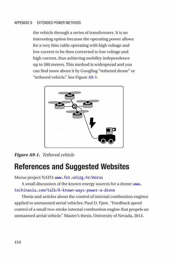
“tethered vehicle.” See Figure A9-1.
Figure A9-1. Tethered vehicle
References and Suggested WebsitesMorus project NATO: www.fer.unizg.hr/morus
A small discussion of the known energy sources for a drone: www.
techinasia.com/talk/6-known-ways-power-a-drone
Thesis and articles about the control of internal combustion engines
applied to unmanned aerial vehicles: Paul D. Fjare. “Feedback speed
control of a small two-stroke internal combustion engine that propels an
unmanned aerial vehicle.” Master’s thesis, University of Nevada, 2014.
APPENDIX 9 EXtENDED PowEr MEthoDs
417
Tomislav Haus, Marko Car, Matko Orsag, Stjepan Bogdan.
“Identification results of an internal combustion engine as a quadrotor
propulsion system, Control and Automation (MED).” 2017 25th
Mediterranean Conference on, IEEE, 2017, pp. 713–718.
Solar drone article: M. Hasan Shaheed, Aly Abidali, Jibran Ahmed,
Shakir Ahmed, Irmantas Burba, Pourshid Jan Fani, George Kwofie,
Kazimierz Wojewoda, Antonio Munjiza. “Flying by the sun only: The
solarcopter prototype.” Aerospace Science and Technology 45 (2015),
209–214.
Articles on “tethered” drones or drones with specialized electrical
extensions:
Beom W. Gu, Su Y. Choi, Young Soo Choi, Guowei Cai, Lakmal
Seneviratne, Chun T. Rim. “Novel roaming and stationary tethered aerial
robots for continuous mobile missions in nuclear power plants.” Nuclear
Engineering and Technology 48 (2016), no. 4, 982–996.
Christos Papachristos, Anthony Tzes. “The power-tethered uav-
ugv team: A collaborative strategy for navigation in partially-mapped
environments, Control and Automation (MED).” 2014 22nd Mediterranean
Conference of, IEEE, 2014, pp. 1153–1158.
Tethered units for sale: search keywords “tethered drone”
http://sph-engineering.com/airmast
http://elistair.com
Future wireless power of drones and other vehicles as well as a state
of the art on current energy technologies: Chun T. Rim, Chris Mi. Wireless
Power Transfer for Electric Vehicles and Mobile Devices, John Wiley & Sons,
2017.
Compact and robust converters useful for tethered vehicles design:
www.vicorpower.com/
APPENDIX 9 EXtENDED PowEr MEthoDs
419© Julio Alberto Mendoza-Mendoza, Victor Gonzalez-Villela 2020 J. A. Mendoza-Mendoza et al., Advanced Robotic Vehicles Programming, https://doi.org/10.1007/978-1-4842-5531-5
APPENDIX 10
Summary of the Design of a QuadcopterThe design process of a multicopter is illustrated as a flow diagram. This
contemplates three aspects that are considered standard and frequent
in the design process: the body or vehicle, the brain or autopilot, and the
external control or radio control selection. Notice that the selection of
sensors has been omitted as it is a very variable task among end users.
For example, some users will want cameras, some will prefer LIDARs,
ultrasounds, etc. For more information in this regard, consult this
appendix’s bibliography.
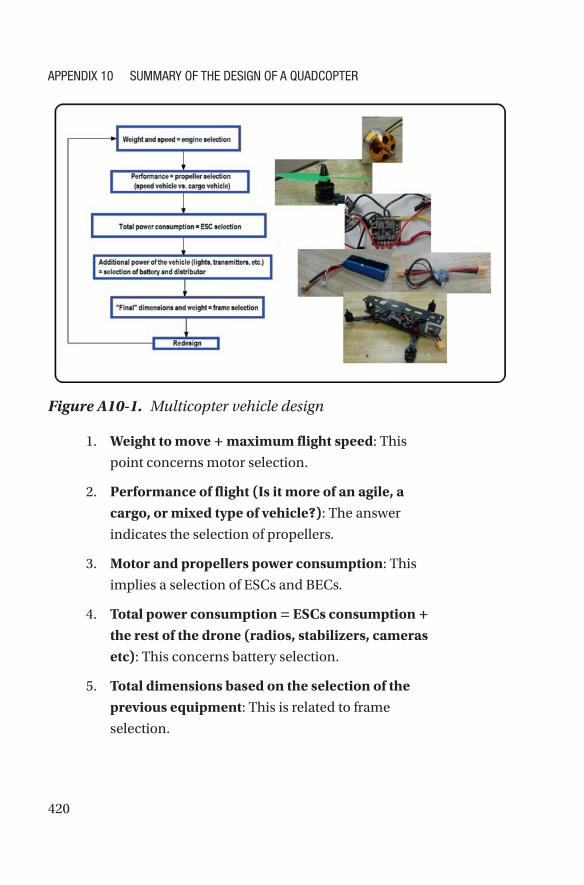
Vehicle DesignThe vehicle design is shown in Figure A10-1.
420
1. Weight to move + maximum flight speed: This
point concerns motor selection.
2. Performance of flight (Is it more of an agile, a cargo, or mixed type of vehicle?): The answer
indicates the selection of propellers.
3. Motor and propellers power consumption: This
implies a selection of ESCs and BECs.
4. Total power consumption = ESCs consumption + the rest of the drone (radios, stabilizers, cameras etc): This concerns battery selection.
5. Total dimensions based on the selection of the previous equipment: This is related to frame
selection.
Figure A10-1. Multicopter vehicle design
APPENDIX 10 SummAry of thE DESIgN of A QuADcoPtEr
421
6. A full design means you’re ready to build.
Otherwise, a redesign means going back to step 1.
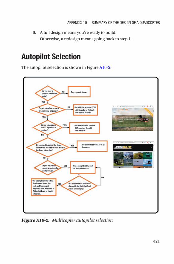
Autopilot SelectionThe autopilot selection is shown in Figure A10-2.
Figure A10-2. Multicopter autopilot selection
APPENDIX 10 SummAry of thE DESIgN of A QuADcoPtEr
422
1. Can the required application be done with manual
operations? Remember that the GUI has a very
robust control, while the SDK allows the reader to
operate with the least detail possible but the control
and its robustness will be designed by the user.
IF the answer is yes, use autopilots based on GUI
type CC3D.
IF the answer is no, use autopilots based on SDKs, if
you know how to program.
2. Does the application demand a particular flight
mode X Y Z and turning angle?
IF yes, you could use Mission Planner scripts or a
simplified SDK.
3. IF no, does the application demand a flight mode
with total angular variation and altitude?
IF yes, look for an extended SDK.
4. IF not, does the application demand independent
control of each engine (for example, a new
prototype that does not exist)?
IF yes, you must look for a full SDK such as
ArduPilot, and a good autopilot such as the
Pixhawk.
5. Is the Pixhawk enough for your task?
IF no, use development boards combined with
autopilots, such as the ErleBrain.
APPENDIX 10 SummAry of thE DESIgN of A QuADcoPtEr
423
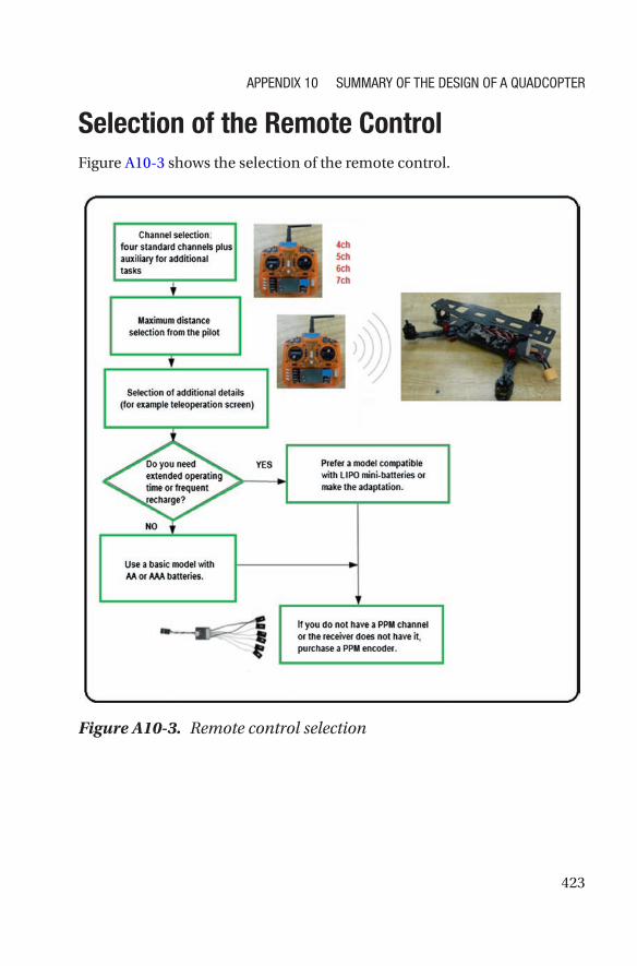
Selection of the Remote ControlFigure A10-3 shows the selection of the remote control.
Figure A10-3. Remote control selection
APPENDIX 10 SummAry of thE DESIgN of A QuADcoPtEr
424
1. How many tasks are required in addition to the four
basic movements? For example, a six-channel radio
where the two additional channels are levers of type
ON/OFF will have a total of four combinations for
four other tasks:
Aux1 On Aux2 On
Aux1 On Aux2 Off
Aux1 Off Aux2 On
Aux1 Off Aux2 Off
Result = four-channel radio + number of extra
channels
2. Determine the maximum range distance.
3. Determine additional features.
4. Do you want an extended operation time?
If yes, opt for a model with optional LIPO battery
power.
5. Does your control have a PPM port? If not, you must
buy an adapter.
References and WebsitesMaker-style books that facilitate the understanding and selection of
various components of a multicopter:
II Davis, Robert James. Arduino Flying Projects: How to Build
Multicopters, from 100mm to 550mm, CreateSpace Independent
Publishing Platform, 2017.
APPENDIX 10 SummAry of thE DESIgN of A QuADcoPtEr
425
Terry Kilby, Belinda Kilby. Getting Started with Drones: Build and
Customize Your Own Quadcopter, Maker Media, Inc., 2015.
Vasilis Tzivaras. Building a Quadcopter with Arduino, Packt Publishing
Ltd, 2016.
A very complete article that deals with the process of designing,
modeling, and controlling a multicopter from the scientific point of view:
Hyunsoo Yang, Yongseok Lee, Sang- Yun Jeon, Dongjun Lee. “Multi-
rotor drone tutorial: systems, mechanics, control and state estimation.”
Intelligent Service Robotics 10, 2017, no. 2, 79–93.
On the use of Python scripts in Mission Planner:
http://ardupilot.org/planner/docs/using-python-scripts-in-
mission-planner.html
https://github.com/ArduPilot/MissionPlanner/tree/master/
Scripts
About the SDK autonomy for the Parrot Bebop: https://bebop-
autonomy.readthedocs.io/en/latest/
On the different platforms, prebuilt drones, and navigation cards
supported by the ArduPilot libraries: http://ardupilot.org/dev/docs/
building-the-code.htm
Alternative project Crazyflie: www.bitcraze.io/getting-started-
with-development/
APPENDIX 10 SummAry of thE DESIgN of A QuADcoPtEr
427© Julio Alberto Mendoza-Mendoza, Victor Gonzalez-Villela 2020 J. A. Mendoza-Mendoza et al., Advanced Robotic Vehicles Programming, https://doi.org/10.1007/978-1-4842-5531-5
APPENDIX 11
Working with Header FilesYou probably want to work with additional header files beyond those
already included in the extended header (defines.h, configs.h,
and compat.h). This is possible under the following restrictions. The
distribution of ArduPilot libraries included with this book is limited for use
with internal libraries (internal with respect to the project). This way, it is
only possible to use internal header files (which are defined in the project
folder). Also, these header files must contain declarations and definitions
in a single file with the extension .h (not as in the common way found in
many software projects where the declaration is indicated in an .h file and
the definition in a .c or .cpp file).
Having said that, we recommend generating header files that contain
very simple definitions, constants, or functions (port registers, control
constants, communication speeds, etc.).
Any other way to use header files, such as using commands from
external libraries other than ArduPilot, is left as your responsibility.
This way, you can search in forums or verify through them if an
improvement is available with recent versions or alternative versions of the
ArduPilot libraries.
428
ATTENTION: Do not attempt to invoke the extended header within a
header file. For reasons of compilation with the distribution included with
this book, Eclipse does not detect the extended header encoded within the
header file. You must copy the extended header to the main file for each
one of your projects.
Having indicated the characteristics and restrictions of these header
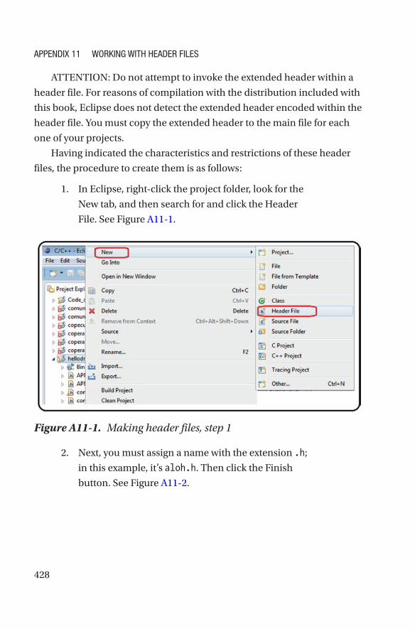
files, the procedure to create them is as follows:
1. In Eclipse, right-click the project folder, look for the
New tab, and then search for and click the Header
File. See Figure A11-1.
Figure A11-1. Making header files, step 1
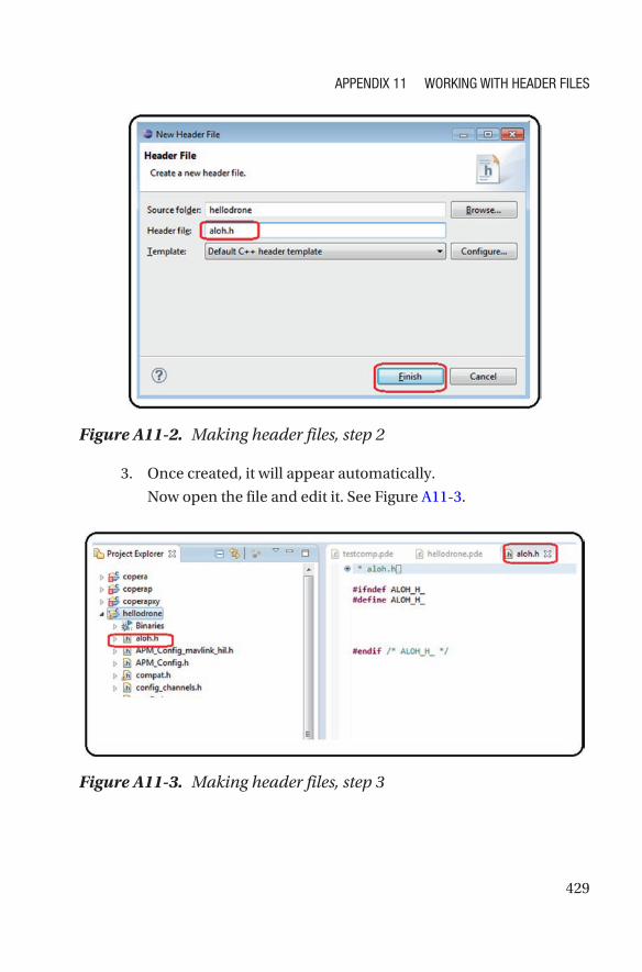
2. Next, you must assign a name with the extension .h;
in this example, it’s aloh.h. Then click the Finish
button. See Figure A11-2.
APPENDIX 11 WorkINg WIth hEADEr FIlEs
429
Figure A11-2. Making header files, step 2
3. Once created, it will appear automatically.
Now open the file and edit it. See Figure A11-3.
Figure A11-3. Making header files, step 3
APPENDIX 11 WorkINg WIth hEADEr FIlEs
430
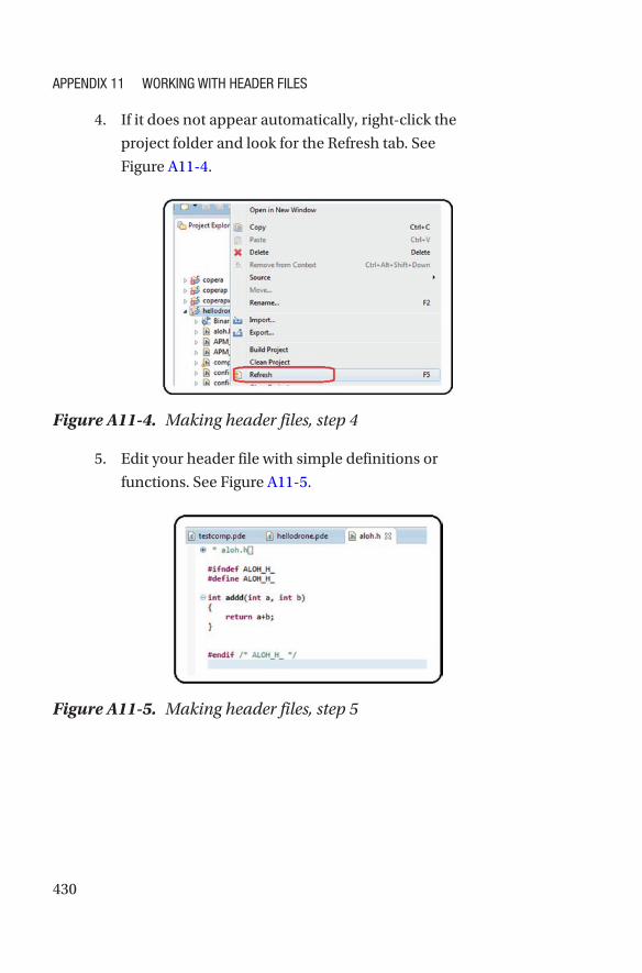
4. If it does not appear automatically, right-click the
project folder and look for the Refresh tab. See
Figure A11-4.
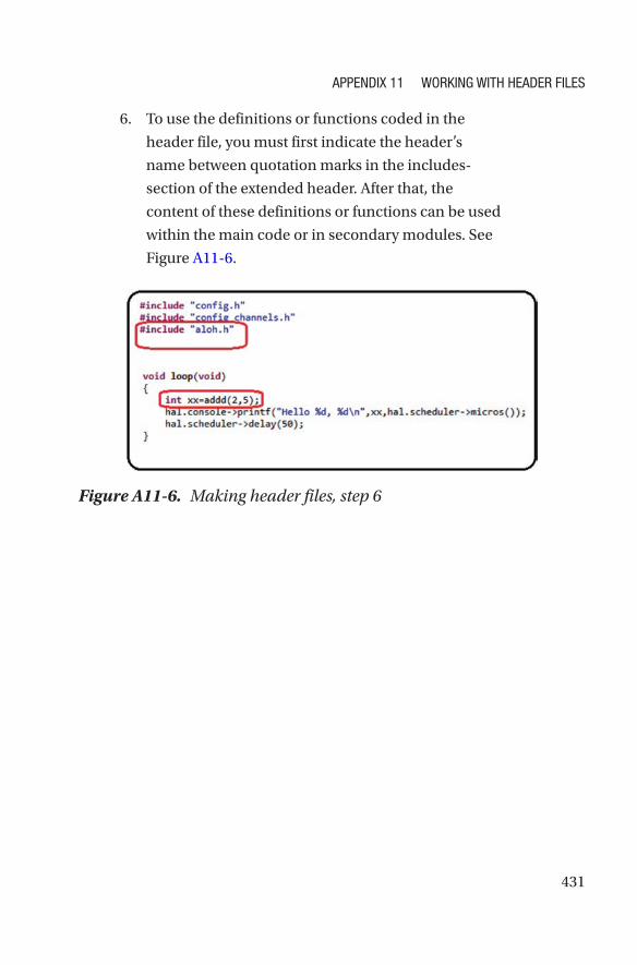
Figure A11-5. Making header files, step 5
Figure A11-4. Making header files, step 4
5. Edit your header file with simple definitions or
functions. See Figure A11-5.
APPENDIX 11 WorkINg WIth hEADEr FIlEs
431
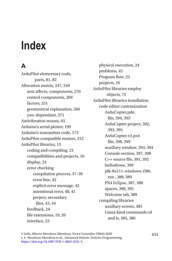
6. To use the definitions or functions coded in the
header file, you must first indicate the header’s
name between quotation marks in the includes-
section of the extended header. After that, the
content of these definitions or functions can be used
within the main code or in secondary modules. See
Figure A11-6.
Figure A11-6. Making header files, step 6
APPENDIX 11 WorkINg WIth hEADEr FIlEs
433© Julio Alberto Mendoza-Mendoza, Victor Gonzalez-Villela 2020 J. A. Mendoza-Mendoza et al., Advanced Robotic Vehicles Programming, https://doi.org/10.1007/978-1-4842-5531-5
Index
AArduPilot elementary code,
parts, 81, 82Allocation matrix, 247, 249
arm affects, components, 270control components, 269factors, 251geometrical explanation, 266yaw-dependant, 271
Antivibration mount, 65Arduino’s serial plotter, 199Arduino’s transmitter code, 173ArduPilot-compatible motors, 212ArduPilot libraries, 15
coding and compiling, 23compatibilities and projects, 16display, 24error checking
compilation process, 37–39error line, 42explicit error message, 42intentional error, 40, 41project, secondary
files, 43, 44feedback, 24file extensions, 19, 20interface, 23
physical execution, 24problems, 45Program flow, 23projects, 16
ArduPilot libraries employ objects, 75
ArduPilot libraries installationcode editor customization
ArduCopter.pde. file, 394, 395
ArduCopter project, 392, 393, 395
ArduCopter-v2.px4 file, 398, 399
auxiliary window, 393, 394Console section, 397, 398C++ source file, 391, 392hellodrone, 399jdk-8u111-windows-i586.
exe., 388, 389PX4 Eclipse, 387, 388spaces, 390, 391Welcome tab, 389
compiling librariesauxiliary screen, 385Linux-kind commands cd
and ls, 385, 386
434
PX4 ArduCopter firmware, 386, 387
PX4 Console, 384, 385px4-v2 command, 386
Pixhawk drivers, 381–383software download, 380terminal test, 404, 405toolchain, 383, 384uploading .px4 files
Firmware tab, 400, 401load custom software, 401, 402location, 402, 403Mission Planner, 399, 400, 403warning, 400
websites, 405Auxiliary robotics components
battery tester/monitor, 59brushless motors, 47, 49distributors, 60embedded on-board
computer, 66ESC, 49, 50fasteners, 64frame, 52function, 71, 72GPS module, 59LIPO battery, 57, 58passive antivibration modules, 65power module, 61propellers, 51remote control, 65silicon wire, 62, 63
special connector, 53–56special Pixhawk components, 67structure, 71telemetry module, 56, 57thermofit, 63, 64
BBias translation concept, 305Bicopter, 261Brushed/DC motors, 47Brushless (BLDC) motors, 47, 49,
174, 243components, 175description, 175equipment, 175keyword, 184, 187process, 175Servos and Radios, 182, 184testing with Arduino, 176, 177writing to, 178, 179
CClass definition, 74Coaxial system, 263Code optimization
files, 195hardware and software, 203Pixhawk autopilot
connection, 195, 202RC output signals, 199robots, 194writing to DC motors, 193, 198,
200, 201
ArduPilot libraries installation (cont.)
INDEX
435
writing to motors, 187, 189–191, 193
Computational efficiency, mathematical equality, 68, 69
Control methodsclosed vs. open loop, 292–293theory and practice, 293
allocation matrix, 294linear systems control, 298roll and pitch, 301, 302sinusoidal forces, 296spring and damper, 295translational and rotational
models, 297tuning process, 296
DData use and storage, 213, 215–219Decoupled tasks
altitude, 286characteristics, 287, 288control components, 289optional tasks
motor, 287trajectory, 286
orientation, 286physical explanation, 290position, 286remote control, 286
Dirty integration/rectangular approximation algorithm, 124
Distributors, 60
Dronebody frames, 245, 246coordinate frame, 254geometric configuration, 253matrix form, 260, 261movements, 252multicopter, 248problems, 249, 250propeller, 247propulsion/allocation
matrix, 247, 252–259quadcopters, 251reference frames, 244, 245rotational frames, 255self-rotating effect, 253
Drone flight implementationcomponents, 308label, 309tasks, 309
Dynamic rotational equations, 277
body frame, 277forces and torques, 280pqr notation, 278trigonometric properties, 279
Dynamic translation equations, 275, 276
EElectronic speed
controller (ESC), 48Euler angles vs. pqr variables, 278Extended code, setup, 361, 362
INDEX
436
Extended energy methodsdirect electrical
connection, 415internal combustion, 415solar energy, 415websites, 416, 417
Extended header, 363–365, 367, 368External Position Sensors
Reading (GPS)dirty integrator
algorithm, 125, 126read planar positions and
velocities, 127, 129
FFasteners, 64Flight_modes() function, 343Flight modes, 282
aggressive, 283ArduPilot libraries, 285
automatic mode, 285classifications, 284vs. control methods vs. task
planning, 283kinodynamic, 283rudeness, 284soft, 283
Functional code, 369–371, 373–375
GGPS module, 59
HHeader files, 428–431Hovering, 286
I, JInput and output operations
altitude and vertical velocity readings, 123, 124
analog sensors, reading, 130, 132
angular singularity, 119, 120angular velocity readings,
121, 122auxiliary channels, 112, 113battery reading, 138, 139command, 89digital reading and
writing, 136, 137drift, 118electrical noise, 117filtering signals, 133, 134, 136header
code, 94commands, 92, 93
LED, using visual alerts, 141, 142
map values, function, 90position and orientation internal
sensors reading, 116saturation values, function, 91setup, 95
INDEX
437
state machine, 113–115terminal reading, 95–101
Installation and coding, 79–81
KKeyboard motor calibration, 184
LLIPO battery, 58Log_Write functions, 347Lyapunov methods, 296
MMap function, 107Mathematical stabilization
methods, 296microSD card, 220
flight data, 220–230Mission planner interface, 220Module, 72, 73, 100Motor effect
roll/pitch lever, 243throttle lever, 242yaw lever, 242
Multicopter design processautopilot selection, 421, 422remote control
selection, 423, 424vehicle design, 419–421websites, 424, 425
NNewton’s second law, 275Normalization, 267
OOmnidirectionality, 411, 412
websites, 412–414Orientation and position, 77–79
PPixhawk autopilot
clones vs. originals, 13commercial autopilot vs.
design, 14custom code, uploading, 25–29data types, 20definition, 3development card, 3, 4features, 9, 10GUI vs. SDK interfaces, 6ports, 10–12PPM, PWM, 1000/2000,
implementation, 21, 22projects, 16SDKs, types, 7, 8types, 5
Pixhawk code, 171Pixhawk’s receptor code, 172Pixhawk type X configuration, 241Pixhawk type X quadcopter, 265
INDEX
438
Planar vertical takeoff and landing (PVTOL), 261
coaxial, 261, 263control analysis, 263non-coaxial, 264
Polling method, 158, 159, 162, 165, 168, 169, 171
Programming ArduPilot code, models, 83, 84
Propellers, 51Propulsion matrix, 247, 264, 268
QQuadcopter
coordinate frames, 246linear-attitude equations, 281non-linear equations, 280resume of, 282
RRadio control motor calibration, 182Radio reading
control signals, 106, 107limiting values, 111map function, 107saturation function, 109, 110tests, 103–105
Read_radio() function, 342Real time mode
control.pde module, 343, 344data.pde module, 348–350, 352hovering control, quadcopter,
338–341
Module radio.pde, 342pose.pde module, 352, 354state machine, 345–347
Real-time working environment, ArduPilot libraries
execution time, measuringruntime task, 333scheduler, 334, 335system clock invoation,
330–332linker, 325parts, 328, 329scheduler, 326, 327
Remote control components, 66
SSaturation function, 109Save_data() function, 347Scheduler, 326SDK commands, comparison,
357–360Serial.write() command, 171Servomotors, 206, 208, 209, 211Signal biasing, effects of, 306Signal saturation, effects of, 308Software development kit (SDK), 5Special Pixhawk components, 67Spring-damper type
system, 293, 295Stepper motors, 204
ArduPilot libraries, 204Pixhawk, 204, 205
Symmetric quadcopter angles, 271
INDEX
439
T, UTelemetry module, 56, 57Tethered vehicle, 416Thematic keywords, 377, 378Thermofit, 63, 64Thrust vectoring method, 407–409Time management, ArduPilot
libraries, 231, 232, 234, 235Translation value, 250Trigonometric properties, 279
VVariable, 70Velocity kinematic relations
angular variations, 274Euler angles, 273frames vs. translational
velocities, 274planar axes, 273translational velocities, 273
WWired/wireless serial
communicationchecksum method
reception, 155, 156sending, 155
components, 143connection, 144data reception process and
recap, 153data verification
procedure, 154description, 143development boards, 174external sensors, 171, 172geometrical interpretation
of module and residue, 154
polling method, 158, 159, 162, 165, 168, 169, 171
sending data, 149–151telemetry device configuration,
144–148UART devices, 143XOR type checksum, 156, 157
X, Y, ZXOR checksum
method, 156, 157
INDEX
Related Documents