Calhoun: The NPS Institutional Archive Theses and Dissertations Thesis Collection 2002 Comparison of approaches for determining the failure of stiffened cylindrical shells Price, David J. (David Joseph) http://hdl.handle.net/10945/11023

Welcome message from author
This document is posted to help you gain knowledge. Please leave a comment to let me know what you think about it! Share it to your friends and learn new things together.
Transcript

Calhoun: The NPS Institutional Archive
Theses and Dissertations Thesis Collection
2002
Comparison of approaches for determining the
failure of stiffened cylindrical shells
Price, David J. (David Joseph)
http://hdl.handle.net/10945/11023

Comparison of Approaches for Determining the Failure of Stiffened Cylindrical Shells
by
David J. Price DISTRIBUTION STATEMENT A Approved for Public Release
B.S. Mechanical Engineering Distribution Unlimited North Carolina State University, 1991
M.S. Engineering The Catholic University of America, 1999
Submitted to the Department of Ocean Engineering and the Department of Mechanical Engineering in Partial Fulfillment of the Requirements for the Degrees of
Master of Science in Naval Architecture and Marine Engineering
and
Master of Science in Mechanical Engineering
at the Massachusetts Institute of Technology
June 2002
© 2002 David J. Price. All rights reserved.
The author hereby grants to MIT permission to reproduce and to distribute publicly paper and electronic ^copies of this thesis document in whole or in part.
1/ ~ Signature of Author
Certified by K^JV Iü^AJOA
Department of Ocean Engineering and the Department of Mechanical Engineering
May 15,2002
Certified by KJUJ^L^LL*\ David V. Burke, Senior Lecturer
Department of Ocean Engineering Thesis Supervisor
Nicholas M. Patrikalakis, Profess
Accepted by
Accepted by
Mechanical Engineering £or of Engineering
Thesis Reader
So Chairman, Depart:
essor of Ocean Engineering Committee on Graduate Students
Department of Ocean Engineering
Ain A. Sonin, Professor of Mechanical Engineering Chairman, Department Committee on Graduate Students
Department of Mechanical Engineering
20020822 009

Page intentionally left blank

Comparison of Approaches for Determining the Failure of Stiffened Cylindrical Shells
by
David J. Price
Submitted to the Department of Ocean Engineering and the Department of Mechanical Engineering in Partial Fulfillment of the Requirements for the Degrees of
Master of Science in Naval Architecture and Marine Engineering and
Master of Science in Mechanical Engineering
ABSTRACT
The thesis compares the analytical solution, two marine classification society design rules, and two design guides against experimental results for predicting the failure modes (general instability, axisymmetric buckling, and asymmetric collapse of the shell [lobar buckling]) and failure pressures of ring-stiffened cylinders
The analytical solution is first summarized based on several sources. The design rules for the classification societies and the design guidance from two sources are then presented with brief explanations for each one. The design rules used are: American Bureau of Shipping (Rules for Building and Classing Underwater Vehicles, Systems, and Hyperbaric Facilities, 1990) and Germanischer Lloyd (Rules for Underwater Technology, 1988). The design guides used were Society of Naval Architects and Marine Engineers (Submersible Vehicle Systems Design, 1990) and Massachusetts Institute of Technology Course 13A Professional Summer Notes (MIT 13A Submarine Design Trends, 2001).
The United States Navy Naval Sea Systems Command, Submarine Structural Integrity Division supplied experimental data for four cylinders that covered the failure modes and allowed comparison between experiment and design rules / guidance.
The comparison of experimental to predicted data found that the design codes and design guides performed adequately in predicting axisymmetric yield and asymmetric buckling. The performance of the design codes and guides in predicting failure by general instability was unsatisfactory. For the experimental failures by general instability, the design codes and guides predicted significantly higher failure pressures than those experimentally determined; resulting in the design codes and guides actually predicting failure by axisymmetric yield in stead of general instability. These inconsistencies in the predictions of failure mode and pressures for general instability should be further explored to determine causes and corrections.
Thesis Supervisor: David V. Burke Title: Senior Lecturer
Thesis Reader: Nicholas M. Patrikalakis Title: Professor of Ocean and Mechanical Engineering
Kawasaki Professor of Engineering

Acknowledgements
I would like to thank Mr. William Will of the Naval Sea Systems Command, Submarine Structural Integrity division for providing the experimental data for the thesis and providing invaluable knowledge into the mechanics of cylindrical failures.
1 would also like to thank Dr. David Burke for not only being a very supportive advisor and providing the impetus for the thesis, but for giving much needed and timely guidance throughout the analysis and writing processes.
Lastly I would like to thank Matt Graytek and Stephanie Norris for producing some initial programming of the design rules. These were very important starting points for my analyses.
This thesis is dedicated to:
My parents: William F. Price and Letitia M. Price and My wife: Shelly L. Price

Table of Contents
Table of Contents 5 List of Figures 6 List of Tables 6 List of Appendices 6 Chapter 1: Introduction 7
1.1 Failure Types 7 1.2 Concept Exploration 8 1.3 Analysis Techniques 8 1.4 Design Rules and Guides Examined 9
Chapter 2: Overview of Ring-Stiffened Cylindrical Shells 11 2.1 Terminology 11
2.1.1 Material Properties 11 2.1.2 Geometry 12
2.1.2.1 Cylinder Geometry 12 2.1.2.2 Stiffener Geometry 12
2.2 Classification of Stiffeners 14 2.3 Stresses in Cylinders 15
Chapter 3: Analytic Solutions 17 3.1 History of Analyses 17 3.2 Current Theory 18
3.2.1 Axisymmetric Yield 19 3.2.2 Asymmetric Buckling (Lobar Buckling) 23 3.2.3 General Instability 24
Chapter 4: The Design Rules and Analysis Tools 27 4.1 American Bureau of Shipping (ABS) 27
4.1.1 Axisymmetric Yield 27 4.1.2 Asymmetric Buckling 28 4.1.3 General Instability 29
4.2 Germanischer Lloyd 30 4.2.1 Axisymmetric Yield 30 4.2.2 Asymmetric Buckling 35 4.2.3 General Instability 35
4.3 Society of Naval Architects and Marine Engineers (SNAME) 36 4.3.1 Axisymmetric Yield 36 4.3.2 Asymmetric Buckling 37 4.3.3 General Instability 38
4.4 MIT 13A Professional Summer Submarine Design Trends 38 4.4.1 Axisymmetric Yield 38 4.4.2 Asymmetric Buckling 40 4.4.3 General Instability 41

Chapter 5: Experimental Results 43 5.1 NAVSEA Test Cylinders 43
5.1.1 Cylinder l.d 44 5.1.2 Cylinder l.f 45 5.1.3 Cylinder 2.a 45 5.1.4 Cylinder 2.c 47
5.2 Calculation to Experiment Comparison 4g
Chapter 6: Conclusions 53 6.1 Comparative Analysis Review 53 6.2 Agreements and Differences 54 6.3 Applications of the Models 55 6.4 Further Areas of Study 55
References 57
List of Figures
Figure 1: Cylinder and Stiffener Geometry 14 Figure 2: Basic Cylindrical Shell Stresses 16 Figure 3: Failure Pressure Ratio versus Slenderness Ratio 19 Figure 4: Coordinate System for a Cylindrical Shell 20 Figure 5: Test Cylinder l.d Schematic 44 Figure 6: Test Cylinder 1 .f Schematic 45 Figure 7: Test Cylinder 2.a Schematic 45 Figure 8: Test Cylinder 2.c Schematic 47
List of Tables
Table 1: Comparison of Design Rule Calculations to Experimental Results 48 Table 2: Cylinder 1 .f Elastic General Instability Failure Pressures 50 Table 3: Cylinder 2.c Elastic General Instability Failure Pressures 51
List of Appendices
Appendix A: Codes for Test Cylinder 1 .d 59 Appendix B: Codes for Test Cylinder 1 .f 99 Appendix C: Codes for Test Cylinder 2.a 141 Appendix D: Codes for Test Cylinder 2.c 183

Chapter 1: Introduction
The widespread use of stiffened cylinders in the marine industry has generated many
studies into the stability and failure of these cylinders and methodology for failure prevention.
Of primary concern to entities involved with the use of manned submersible vehicles is the
design of ring-stiffened cylinders; this type of stiffened cylinder is used for significant portions
of the pressure hull. Over a hundred years of theoretical and experimental research has led to a
general understanding of the mechanics of failure for these cylinders. Based on this research,
marine Classification Societies, such as the American Bureau of Shipping (ABS), the American
Petroleum Institute (API), NORSOK and Germanischer Lloyd (GL) have promulgated design
rules to provide guidelines on the design and building of stiffened cylinders for safe operation.
Other design and analysis theories and guidance are available in texts such as those published by
the Society of Naval Architects and Naval Engineers (SNAME).
1.1 Failure Types
There are three primary types of failure of ring-stiffened cylinders. They are
axisymmetric yielding (AY) of the shell between stiffeners, asymmetric buckling of the shell
between stiffeners (Lobar), and general instability of the shell and stiffeners (GI). Axisymmetric
yield generally occurs when the shell is relatively heavy and the frames are closely spaced.
Lobar buckling can occur when the shell is relatively light and the frames are strong and widely
spaced. General Instability can occur when the cylinder is relatively long, the shell is thin and
the frames are small. General Instability is very dependent upon eccentricities in the shell, which
tend to lower the cylinder's resistance to the General Instability mode. [1]

As analyzed here General Instability is presumed to occur in the elastic region of the
stress - strain curve of the material. Cylinders also fail by inelastic General Instability, which
occurs at significantly lower pressures than that of elastic General Instability. Failure by this
mode is not addressed by the design rules. Other modes of failure also exist such as multi-wave
instability, which is a sub-type of General Instability. It can occur in both the elastic and
inelastic regions. Again the design rules do not address this failure mode. Several of the
classification societies address stiffener tripping, which is the rotation of a stiffener away from
perpendicular with the shell, however stiffener tripping is usually a precursor to general
instability and is not a separate major failure mode.
1.2 Concept Exploration
For this thesis, an emphasis was placed on exploring how the various design rules
predicted failure of cylinders that replicate modern submarine design (i.e. the shell was relatively
thick compared to the diameter of the cylinder). This was facilitated by experimental failure data
from the U.S. Navy's Naval Sea Systems Command (NAVSEA) Submarine Structural Integrity
Division. The analysis was limited to ring-stiffened cylinders to remain consistent with the
primary concern of the thesis. The test cylinders that were chosen had failed in all three possible
modes, allowing for comparison of the design rules in all modes of failure. .
1.3 Analysis Techniques
For the analyses, the design rules for the various classification societies and design
guidance were programmed into MATHCAD™ for consistency of approach, ease of symbolic
representation, and quickness of computations. The analytical solution was also programmed
into MATHCAD™ for comparison. The experimental data from the four test cylinders were

then input into each computer code. The codes gave a failure pressure for each type of failure.
The lowest calculated pressure was then considered the failure pressure and the corresponding
mode was designated the failure mode. The failure modes and pressures were then compared
against the experimental results with emphasis placed on agreement between codes and
experiment on failure mode (first priority) and then failure pressure (second priority). If a
different failure mode was predicted than that experimentally found for a particular cylinder, an
analysis was performed for agreement between predicted failure pressures and also the closeness
of the failure mode pressures.
1.4 Design Rules and Guides Examined
There were two classification society design rules examined: The American Bureau of
Shipping (rules from Rules for Building and Classing Underwater Vehicles, Systems and
Hyperbaric Facilities, 1990 Edition) (reference 2) and Germanischer Lloyd {Rules for
Underwater Technology, 1988 Edition) (reference 3). Design guides included: The Society of
Naval Architects and Marine Engineers (SNAME) {Submersible Vehicle Systems Design, 1990)
(reference 4) and the Massachusetts Institute of Technology (MIT) Course 13A Professional
Summer (13A PS) Submarine Design Trends Course notes (reference 5) was also used. The 13A
PS is based upon the 1967 version of the SNAME publication Principles of Naval Architecture
(PNA) with some modifications determined by Harry Jackson (CAPT, USN Ret.). A third
classification society, the American Petroleum Institute (API) was planned to be used, however
the immediately available rules from API were not valid for the experimental data used.
However, API does have rules to cover the types of cylinders examined here.
Analytic solutions for the three failure modes were gathered from several sources. These
sources included Hydrostatically Loaded Structures: The Structural Mechanics, Analysis and

Design of Powered Submersibles by William Nash (reference 6), Principles of Naval
Architecture, 1967 edition (reference 1), a David Taylor Model Basin technical paper by J.G.
Pulos and V.L. Salerno (reference 7), and several journal articles from the Transactions of The
Royal Institution of Naval Architects by S. Kendrick (reference 8) and C. T. F. Ross (reference
9).
In Chapter 2 a brief discussion on the terminology of ring-stiffened cylindrical shells is
produced along with a short derivation of the basic stresses in these cylinders. Chapter 3
contains the summary of analytic solutions used to predict failure (the solutions are not re-
derived), Chapter 4 has the summary of the design rules and guides from the various sources.
Chapter 5 describes the test cylinders and then compares the results from experiment to the
results predicted by the design rules and guides. Chapter 6 summarizes the results with
recommendations for further study.
10

Chapter 2: Overview of Ring-Stiffened Cylindrical Shells
Ring-stiffened cylinders are the prevalent construction type in the mid-bodies of modern
submersibles. The stiffeners provide additional strength to the shell that is required for the
pressure differential between the external hydrostatic pressure and the internal, approximate
atmospheric pressure. [6]
2.1 Terminology
The various classification societies use slightly different terminology for the cylinder
geometries and properties. In the computerized design rules, the symbols used by each
classification society are generally used to avoid confusion between the published code and the
programs. All of the codes require computation of the moment of inertia (I) of the ring stiffener
and the moment of inertia (Ie) of an effective ring stiffener (the frame and some length of
attached shell). The formulas for I and Ie came from [10].
The terminology can be divided into two categories: material properties and geometry.
All stresses and pressures are in pounds per square inch (psi), lengths are in inches (in), areas are
in square inches (in2) and moments of inertia are in inches to the fourth power (in4).
2.1.1 Material Properties
1) Modulus of Elasticity (E): The slope of the linear region of the stress-strain curve of a given
material. For all of the calculations a value of 3 X 10⁷ psi (a common value for steel) was used.
2) Poisson's Ratio (v or u): The ratio of lateral strain to axial strain in a material. For all
calculations, a value of 0.3 (a general figure for steel) was used.
11

3) Yield Strength (o\ or fy or k): An arbitrary value for materials marking the onset of plastic
deformation of a material. This is usually considered the point of 0.2% permanent strain. This
value is of primary concern in the axisymmetric yield calculations. This parameter ranged in
value from 65,500 psi to 157,000 psi.
2.1.2 Geometry
2.1.2.1 Cylinder Geometry (see Figure 1)
1) Cylinder Length (L or Lb or Lc): Overall length of the cylinder between supports. This varies
by cylinder and is of primary concern for General Instability calculations
2) Shell Mid-plane Radius (R): Radius from centerline of cylinder to the shell mid-plane.
3) Shell plate thickness (t or tp or s or h): Thickness of the cylinder shell plating.
2.1.2.2 Stiffener Geometry (see Figure 1)
1) Length between Stiffeners (L or Lf or Ls): Distance between centerlines of adjacent stiffeners.
This distance was assumed to be constant for each cylinder. This dimension is important for
both Axisymmetric Yield and Lobar Buckling.
2) Web Height (hw): Length of the web for 'T' stiffeners or the height of the stiffener for
rectangular stiffeners.
3) Web Thickness (tw): Thickness of the web for T stiffeners or the thickness of the stiffener for
rectangular stiffeners.
4) Flange Breadth (bf): Width of the flange for T stiffeners. This value is set to zero for
rectangular stiffeners.
5) Flange Depth (d): Thickness of the flange for T stiffeners. This value is set to zero for
rectangular stiffeners.
12

6) Stiffener Depth (H): The distance from the shell to the end of the stiffener. This is the
stiffener height for rectangular stiffeners and the web height plus the flange depth for 'T'
stiffeners.
7) Faying Length (b): The distance of contact of the stiffener to the shell. It is equal to the flange
width for 'T' and rectangular stiffeners; if T'-beam or wide-beam (WF) stiffeners are used, then
equal to the flange breadth in contact with the shell.
8) Effective Length of the Shell (Le): A length of shell to be considered as part of the combined
stiffener and shell used in the General Instability analyses. This length is usually a fraction of
the stiffener spacing, but many times will be equal to the stiffener spacing.
9) Area of the stiffener (A): Cross-sectional area of the stiffener.
10) Effective Area of the stiffener (Aeff): Cross-sectional area of the combined stiffener and
effective length of shell or a modified area of the stiffener (A) based on the location of the
stiffener.
11) Moment of Inertia (I): Area moment of inertia of the dedicated stiffener, used by some codes
as part of the calculation for the effective moment of inertia.
12) Effective Moment of Inertia (Ieff): Area moment of inertia for the combined stiffener and
shell, used for General Instability calculations.
13

Figure 1: Cylinder and Stiffener Geometry
2.2 Classification of Stiffeners
There are several methods to classify stiffeners. Of importance to the analysis of
cylinders is the location of the stiffener: either internal or external to the cylinder shell. Both
types are used for cylinder construction; slight modifications to the design rules (concerning
effective areas and moments of inertia) are required based on the location. External stiffeners of
equal size to internal stiffeners require more material because of the greater circumferential
length but offer the advantage of freeing spacing within the cylinder for equipment / living space.
[5]
14

Another classification of stiffeners are field (light / non-heavy) and heavy (king frame)
stiffeners. Heavy stiffeners are substantially larger than the field stiffeners and are used to
reduce the effective length of the cylinder for general instability concerns. Field stiffeners are of
uniform size, shape, and spacing. For the current analyses no heavy stiffeners were used.
2.3 Stresses in Cylinders
A brief discussion of stresses in cylindrical shells is required to setup the derivation of
the structural mechanics in support of the analytical solution. As a starting point, a cylinder can
be considered a thin-walled structure (shell) if the ratio of the mid-plane radius to the wall
thickness is greater than ten. This assumption allows the determination of the stresses by statics
alone. [10] All of the cylinders considered are treated as shells. A second assumption in the
analysis is to consider the hydrostatic pressure as constant across the cylinder.
Cylindrical shells, exposed to hydrostatic pressure, have two basic stresses imposed by
the pressure: hoop stress and axial stress. The equations for the stress are:
1) Hoop (circumferential) Stress: <JH=^—- (1)
2) Axial Stress: ^ = — (2) * It
Where p is the external pressure, R is the shell mean radius and t is the shell thickness. Figure 2
shows the derivation of these two equations.
The addition of ring stiffeners to the base shell complicates the hoop stress analysis by
introducing non-uniform deformation of the shell in the radial direction. There is also a beam-
column effect due to the pressure acting in the axial direction. These effects will be addressed in
Chapter 3.
15
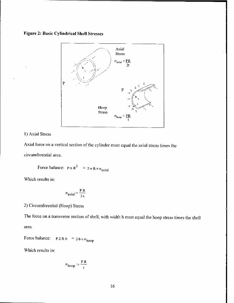
Figure 2: Basic Cylindrical Shell Stresses
Axial Stress
Oaxia] = PR 2t
I *■ y
-i 4-
Hoop Stress
71 ^ f\
^k
^hoop ~ PS
1) Axial Stress
Axial force on a vertical section of the cylinder must equal the axial stress times the
circumferential area.
Force balance: P-TI-R2 = 2-Tt-R-t- 'axial
Which results in:
PR aaxial~ 2.t
2) Circumferential (Hoop) Stress
The force on a transverse section of shell, with width b must equal the hoop stress times the shell
area.
Force balance: p-2-R-b = 2-b-t-o hoop
Which results in:
PR hoop •
16

Chapter 3: Analytic Solutions
Analytic solutions have been proposed and proven for the three major failure modes of
stiffened cylinders. This chapter briefly describes the theories and equations used in the
experimental analyses.
3.1 History of Analyses
The failure of cylinders exposed to external pressure has been studied for almost 150
years. The first attempts at understanding cylinder behavior was done by experiment and
empirical relationships in the 1850's.[6] The first analytic solution for a non-reinforced cylinder
was presented by G. H. Bryan in 1888.[9] The first analysis of a reinforced cylinder appeared in
1913 by R. V. Southwell, followed a year later by a solution to the elastic buckling of a thin shell
proposed by von Mises.[6] In 1934 Widenburg proposed a solution for asymmetric buckling that
is independent of the number of lobes of failure. [6] This equation is the one used in the current
analysis. Solutions for axisymmetric yield were first put forward by von Sanden and Günther in
1920.[9] Viterbo presented a modified version of Sanden and Günther's solution in 1930.[9]
Pulos and Salerno presented a solution that included the Sanden and Günther solution, the
Viterbo modification and a term to account for the bending stress in the cylinder caused by the
axial pressure.[9] The Pulos and Salerno solution is used in this thesis. For elastic general
instability, the first reported analysis was presented by Tokugawa in 1929. In 1954 A. R. Bryant
developed a similar equation using a different methodology. [6]
Analytical work from the 1950's onward has focused on obtaining solutions for different
boundary conditions and more fully reconciling the analytic predictions with experimental
results and to more fully understand the effects of initial imperfections in the cylinder's material
17

and geometric properties. With the advent of power digital computers and the use of finite
element analysis there has been great strides made in understanding the failure of cylinders.
3.2 Current Theory
For this thesis, analytic solutions were collected from several sources for the modes of
failure. A comprehensive theoretical solution that addresses all modes of failure is not presented.
Reference 6 provides a good summation of the currently used analytic solutions.
A first indicator of the failure mode of a cylinder is found by plotting the cylinder's
slenderness ratio (k) against the ratio of the shell buckling pressure(pc) to the hoop pressure at
yield(py) (\|/).[1] The equations for these factors are given below.
X=—° — (n \2
(3)
D
Pc V-- (4)
Figure 3 shows the plot of y versus X. If the slenderness ratio is less than approximately 1.14 the
cylinder should fail by axisymmetric yield; if I is greater than 1.14 then the cylinder should fail
by lobar buckling. If the shell and stiffeners are not of sufficient size, the cylinder may fail by
general instability at a pressure less than that found in Figure 3.[1] By using two assumptions
(the material is steel with v = 0.3 and Ls/D » tp/D) it can be shown that: [1]
1.30
This is the buckling part of the curve in Figure 3.
18

Figure 3: Failure Pressure Ratio versus Slenderness Ratio
1 -1
1.8 -
1.6 -
1.4 - \ 1.2 " Yield \
%
V 0.8 -
o.s - 0.4 -
0.2 -
Buckling
' 1 ' C 0.5 1 1.5
Ä
2 2 5
The treatment of boundary / end conditions of the cylinder is a vitally important factor in
the analytic solutions. The literature is full of discussion on what types of end condition to use,
with the choices ranging from full clamped ends to simply supported ends. The extreme cases
are hard to create in reality and therefore the experimental results tend to fall between the ranges
of predictions. Experiments have shown that partially clamped cylinders provide significantly
higher failure pressures than that predicted by mathematical models utilizing simply supported
ends.[8] For this thesis, no discrete boundary conditions were required to be stated for input into
the equations.
3.2.1 Axisymmetric Yield
As mentioned in section 3.1 axisymmetric yield has been studied since the 1920's. The
solution summarized here was put forward by Pulos and Salerno in 1961. It is based on the
previous works of van Sunden and Günther and Viterbo and includes a previously not included
"beam - column" effect due to the hydrostatic pressure acting in the axial direction of the
cylinder.[7] The governing differential equation is:
19

D
/ \ d4
Vdx / 2 dx2
Et w + w
R2
pi (6)
Where:
D:= Et
>(.-v')
D is the flexural rigidity of the shell 12
The term JL. represents the beam - column effect. It makes the solution to equation (6) a non-
linear function of pressure and was the term neglected in the earlier analyses of axisymmetric
yield. Figure 4 shows the coordinate system used in reference 7 to derive the governing
equation, x, (p, and r are the axial, circumferential and axial coordinates respectfully with u, v,
and w being the corresponding displacements. [7]
Figure 4: Coordinate System for a Cylindrical Shell
20

Following typical practice in the solution of non-homogeneous differential equations the
general solution of the governing equation can be written as the sum of the solution of the
homogeneous equation and a particular solution. [6] The solution to the homogeneous equation
produces four roots (A4-A4). By analysis, placement of the origin of the coordinate system to take
advantage of symmetry, and trigonometric identities, the general solution can be given as:
w— i? cosh/l,x + F cosh/Lx (1 ) 1 ^ Et 2 (7)
where B and F are arbitrary constants which can be found by applying boundary conditions to
the equation.[7]. After further mathematical substitutions several dimensionless parameters were
introduced into the solution to allow easier solving of the problem. Four of these parameters (Fi-
F4) were transcendental functions based on the geometry of the cylinder. These functions were
originally graphed to allow for a relatively quick solution to be found for a given cylinder.
Finally an equation for the failure pressure of a given cylinder was determined. This equation
along with the dimensionless parameters is given below.
Pc'=
yU + denoml - denom2
(8)
Where:
denoml := A F22 + F2.F4-(l-2-p)-
denom2 := | — |A- F2 - H-F4- 0.91
f I 0.91 ^ + F4
2-(l - n + n2). ' 0.91 ^
2
l-n
21

A
y:=
a
a + ß + (l-ß)-F,
2-E [tt^)lß
1 i Tii :=—-vi -y
n2:=-VTT^
fcuv). R-t
Fl:=- coshfrij-0) -COS(TI2-ö)
F2:=
F3:=
9 cosh^j-eJ-sinh^Ti j-e) cos(r]2-0)sin(ri2-0)
cosh^Ti ,e)sin(ri2e) sinh(r| ^eVcosfojo)
^2 nj
cosh(tij-ej-sinh^,-e) cosfr|2e)sin(Ti2e)
Til T)2
cos(ti2e)sin(T}2e) cosh^Tij-eJ-sinh^Ti j-e)
~ Tl2 ^1
F4:=
Jl-u2 cosh(Tlr0)sinh(Tli-0) cos^2eVsinfTi2-0)
Til Tl2
cosh^Ti j-e)sin^Ti2e) sinhfri j9)cos(r|2e)
2 cosh^j-ejsinh^Tij-ej cos(Ti2-0)sin(r|2-0)
Tii n2
An iterative process is required for the general case where the parameter y is not zero. The
process begins with assuming that y is zero, finding the failure pressure then recalculating y and
22

solving the equations for the failure pressure again. Usually only two to three iterations are
needed for satisfactory convergence of the failure pressure. [7]
3.2.2 Asymmetric Buckling (Lobar Buckling)
Asymmetric buckling is characterized by circumferential lobes between ring stiffeners.
As noted above this mode of failure will occur when the cylinder's slenderness ratio is relatively
high. This can be further characterized by a relatively thin shell thickness and widely spaced
stiffeners.fi] R. von Mises first proposed a solution to the buckling of un-stiffened cylinders
under hydrostatic pressure in 1929. He assumed sinusoidal displacements in the axial and
circumferential directions to enable solving of a set of linearized partial differential equations
that represented the elastic action of the shell. [6] He eventually obtained the following equation
for the buckling pressure:
vm R 2 J n-R
n + .5 L
m +
2 n + (T)1
2 :-(,-,2) 12
2 n + 7T-R
(9)
The buckling pressure is dependent upon the number of circumferential lobes (n), which must be
an integer value. This fact requires an iterative process of varying n until the lowest pressure is
determined.
In 1933 Widenburg solved the above equation in way that was independent of n. From
test data the buckling pressures from the von Mises equation and the Widenburg approximation
differ by no more than 3.5%. [6]. Further investigation into the bucking of stiffened cylinders
determined that the Widenburg equation worked very well by replacing the length of the cylinder
by the length between stiffeners. Therefore the Widenburg equation (equation 10), shown
below, is the equation used in the current analyses.
23

2.42 El —
PLB= -D- ,a,3 (10)
i-o.«(IU.^I D ^D;
3.2.3 General Instability
General instability consists of the yielding of both the cylindrical shell and ring stiffeners.
A cylinder may be susceptible when the stiffeners are undersized when compared to the shell
thickness and the cylinder is relatively long.[6] General instability may occur in either the elastic
or inelastic stress region of a material. Elastic general instability is the mode covered by the
available literature and is addressed here. Inelastic general instability has been studied mainly by
government laboratories and most of the knowledge of this failure mode is classified material
and therefore unavailable to the present author. [11]
The first analysis of general instability was presented by T. Tokugawa in 1929. [6] His
methodology considered the failure as a combination of the failure of the ring stiffeners and shell
buckling with each taking place separately. [9] In the 1940's S. Kendrick used a strain energy
methodology to determine the failure pressure. In 1953 A. R. Bryant used a simpler strain
energy method and determined an equation similar to both Kendrick's and Tokugawa's. [1, 9]
The Bryant equation is therefore used for this analysis and is shown below as equation 10.
24

■< (n2-l).E.L E-t X v" ~ l'^le
R PGi- -7 ^ : + — (11)
2 , I n - 1 + —
V 2; .(■^r R3-L
Where:
h
The first term can be considered the failure of the shell and the second term can be
considered the failure of a combined stiffener and an effective length of shell. [6] This effective
length has had much discussion in the literature over the decades. Bryant assumed the length to
be the spacing between the stiffeners, but others have proposed various corrections based on the
cylinder's geometric and material properties.[5] For this thesis, the effective length used was the
stiffener spacing.
Similar to the von Mises buckling pressure determination, the number of circumferential
lobes (n) must be found that minimizes the failure pressure. The number of circumferential lobes
is usually between 2 and 4. [5] The factor X is the number of longitudinal lobes in the cylinder.
25

This page intentionally left blank
26

Chapter 4: The Design Rules and Analysis Tools
The two classification societies' design rules that were utilized were the American
Bureau of Shipping and the Germanischer Lloyd rules. These were chosen for their availability,
their different levels of simplification of equations, their coverage of the specific geometries of
the experimental cylinders, and their inclusion of all three failure modes. The Society of Naval
Architects and Marine Engineers Submersible Vehicle Systems Design and Principles of Naval
Architecture (PNA) were chosen for analysis as SNAME is the primary design society in the
United States and has comprehensive guidelines for cylinders. The MIT 13A Professional
Summer Submarine Design Trends notes were used because of the author's familiarity and the
complete analysis of the failure modes.
4.1 American Bureau of Shipping (ABS)
The ABS design rules, as delineated in the Rules for Building and Classing Underwater
Vehicles, Systems and Hyperbaric Facilities (1990), give a brief and conservative approach for
determining the critical / collapse pressures for each failure mode. The ABS design rules do not
explicitly name the failure modes, but there are distinct equations for the three modes.
4.1.1 Axisymmetric Yield
This mode is designated the yield pressure at midbay and midplane of a cylinder. [2] The
formula accounts for the major parts of the analytic solution, but uses single value functions for
the shell parameters and does not explain the functions of each part of the equation. The rules do
account for the difference between internal and external frames by squaring the mid-plane radius
to stiffener radius ratio for external stiffeners. The base equation follows:
27

Where
t a.
y l-F (12)
A-
F:=-
1--I-G V 2
A + tw-t + 2N-1-L
e
A:=AS-
A:=A_
R — Internal Stiffeners or
External Stiffeners
9:: :[,(- 4 •M
M:= Rt
Q:=
cosh(2Q)-cos(2Q)
sinh(2Q) + sin(2Q)
„ (sinh(Q)cos(Q) + cosh(Q)sin(Q))
sinh(2Q) + sin(2Q) G:=2-
H: _ sinh(2Q) - sin(2Q)
sinh(2Q) + sin(2Q)
4.1.2 Asymmetric Buckling
This is called the Von Mises buckling pressure for a cylinder. It is the Widenburg
approximation that is used by most of the classification societies.
28

2.42-E-
v= 2-R
(.-.') 2-R
0.45 f t Cl
2-R
(13)
The ABS code then has a range of allowable pressures depending upon the ratio of Pm to
Py. Below is the logic for the maximum allowable working pressure for inter-stiffener strength
(Pc). Further safety factors are then applied to lower the allowable pressure in practice.
v= p p m .„ m if < 1
2 P y
/
v
P ^ y
2-R my
m if 1 < — < 3
py
5 „ rm -P if — > 3 6 y Py
4.1.3 General Instability
For the elastic general instability, the ABS code uses the Bryant equation with an
effective length not equal to one frame space. The effective length is given below.
L := min 'U-A/RT
. 0.75 L„ . V s /
The equation for the failure pressure is broken into three parts, but the
total is equivalent to the Bryant formula.
E-t EIe"A2(")
R R3L (14)
Where:
29

A,(n):=
A,(n) + — \n + X ] v 2;
A2(n) := n - 1
X:-- 7I-R
4.2 Germanischer Lloyd
The design rules for Germanischer Lloyd are from Rules for Underwater Technology
(1988 edition). The rules address all three failure modes very thoroughly and flow charts are
provided to aide in programming the code for computer use. These rules also address out-of-
roundness up to a nominal value of 0.5% of the mid-plane shell radius by determining a reduced
allowable pressure.[3]
4.2.1 Axisymmetric Yield
The code for axisymmetric yield resembles the Pulos and Salerno methodology with
some additions to account for the transition of the material into the plastic range during yield.
The methodology consists of first guessing a pressure lower than the failure pressure (the test
cases used 1 psi as the starting point) then iterating through a series of equations to determine the
shell stresses. If the determined shell stress becomes greater than 0.8 of the yield strength of the
material, then a Secant Modulus of Elasticity (Es), a Tangent Modulus of Elasticity (E,) and a
plastic range Poisson's Ratio (up ) is calculated and used to determine the other calculation
factors. The determination of the integer m in equation (14) is described in the code below.
Pm:-Paa'C0' , Tim ,
1 + —■
4
' 7im >
VarLU J (15)
30

Where:
a, :=
4
3- C2 C3
v„ P C,
2
> s' > 2 •R
2-s2-E„
Paa := ■ R2,J3.(,-vp
2
Must iterate on the integer m until trial is < trial2. By meeting this condition the
minimum failure pressure is found (with the minimum m).
trial: CCJ-LJ
trial2:= |— (m+ 1)
H 1 + 2 -Hl-vp H4(H.
Et 1
H4:=
4-ll-Vp )K}
2 _ 2 Cr^-^Cs
1 -v.
Cl:=
H2 H4
H,
31

C2:=
C3:=
( 2 ^
1 - H3 H4
V H
/
( H2H3H4^ 1 +
V VPH1 /
C4 is not used for cylinders without heavy stiffeners.
C5:=aLl
Past:= 2-s E
critical pressure, elastic, calculation factor
p = 1 psi (arbitrary low pressure)
This is the actual starting point of the iteration. A pressure (p) is guessed; the code then
calculates the failure pressure. If the failure pressure is greater than the guessed pressure, the
applied pressure is increased by a set amount. This continues until the two pressures, p and pm
are within a chosen delta of each other. This is essentially the method of Pulos and Salerno with
a simpler method for iterating on the presumed pressure.
G:= Past
C6:=--/rTG
C^-VTTG
C8 :- C5'C6
C9:_C5C7
cio:- (>-4- I 2) s-L,
b ( b
s-L] Lj v'-^Fl
32

0.91 c„- —-j
■J 1 - v
4 cosh (Cgj - cos (CM
CJ cosh(Cgjsinh(Cg) cos(C9J-sin(C9J +
C6 C7
cosh(Cgjsin(CpJ sinh(CgVcos(C9)
C7 + C6
cosh(Cg|sinh(Cgj cos(C9Jsin(C9] H
C F2:=
c7
cos
J3 l^T C,
—I- 1-v
;(c9)sin(c9) cosh(Cg)-sinh(Cg)
C7 ^6
coshlCgVsinhlCg] cos(C9]sin(C9j
% + a, cosh(Cgjsin(Co) sinhlCglcoslCol
C7 C6
(Cg)sinh(Cg) cos(c9)-sin(c9) +
r, r„
F .= l_Z Cn Q
4| 2 cosh 1 1 -v C* c7
The functions Fl through F4 are equivalent to those presented in the analytic solution.
a := i —-—— shape factor s2-R2
The following set of equations determines the stresses at the mid-bay of the shell.
-p-R ao:=
°x:= ao-( 2 + Cl0'Cl ^) Gxl := G°\ 2 ~ Cl0'Cl r?4
V^of1 "C10F2+ vC10CllF4) °<t.l :=tv(! - C10F2 - vC10CllF4)
33

G<l>
I 2 2 °i:=Vax + a<|> -°xa<t>
If the calculated stress is > 0.8k then the following equations are used to determine the
material properties in the elastic - plastic region. The code is somewhat circular, the assumption
was made to determine the strain (EI) from the previously calculated stress then to find a new
stress level by the equation given in the code.
cr := -K0-ox
a:=k- .8+ .2tanh{ 5—-e, -4| ]
k £ := —
E 5 4
V V k 0.8 + 0.2atanh
E 0.8+0.2-f tanhf 5-
V V k E -4
£,:=£ ( 1 -tanhf E
5—E -4 k
1 (I ^ Es]
vr. := — — - - - V p _2 u J EJ
KP=(>-K0+K0:
34

4.2.2 Asymmetrie Buckling
For asymmetric bucking the Germanischer Lloyd code uses a modified version of
equation 9. Therefore the dependence upon the number of lobes is not removed and should give
a better estimate of the buckling pressure. The equation is given below.
Es-ßnl(n) Pnl(n):=- R (16)
Where:
P„i(n):=
\- 2 2 ( 2 c An
+ 1
ri ;
s • n - 1 + A.
12 R2.(,-v2)
n - 1 + .5-X
7I-R
4.2.3 General Instability
For elastic general instability, the code uses the Bryant equation with the effective
moment of inertia based upon the effective length of shell as defined:
Letest^+V^
Letest if Letest < Lj where Li is the frame spacing
Lj otherwise
The base equation for general instability also uses a modified radius (Ro) which is the radius to
the centroid of the combined stiffener and effective length of shell. For this thesis no "heavy" or
"king frame" stiffeners were used, however the code allows for these stiffeners with several
more equations.
Pnla(n):=Po(n) + Pl(") (17)
35

Where:
P0(n) := Esßn2(n)
R
(n2-l)-E-Ie
Pj(n):=
*o\
Pn2(») h4
(n2-l + 1.5.\22){n2 + \2
2)
L:=L3
rc- R A2:=T
4.3 Society of Naval Architects and Marine Engineers (SNAME)
The SNAME code was taken from Submersible Vehicle Systems Design (1990). SNAME
is not a classification society as ABS and Germanischer Lloyd, but it does provide many of the
professional and technical resource material for naval architects in the United States. The
current codes are revised versions of those found in the SNAME publication Principles of Naval
Architecture (1967 edition), reference 1. The code addresses all three modes of failure with the
least complex set of equations of those under current study.
4.3.1 Axisymmetric Yield
For axisymmetric yield, the methodology simplifies the analytic solution by using the
older theory of von Sanden and Günther instead of the solution put forward by Pulos and Salerno
in reference 7. The methodology thus neglects the beam-column effect of the axial pressure.
This is justified by designing the shell to yield vice buckle. [1]
36

f 1 + H-
'_R
0.85-B
1 + ß
\
Where:
(18)
B: V*
Ar + tw-t
6 := 10-L12-U - |i
cosh(e)-cos(e)
sinh(e) + sin(e)
4^V5atN V2y f
V2-Ry R
N:
UN t
H:=-
5olVAr+Vty
R
3-sinh| — -cos — | + cosh 2 ) I 2
^Q^ f a\\
\*/ sinh(e) + sin(e)
4.3.2 Asymmetric Buckling
For Lobar buckling, the code uses the Widenburg approximation equation that is
independent of the number of failure lobes. This is the same as used by ABS.
Pb:= 2.42 E
(,V)
2R
1
2R -°'4<lJ.
(19)
37

4.3.3 General Instability
For general instability, the code uses the unmodified Bryant equation; therefore the
length of shell used in the moment of inertia calculation is one stiffener spacing. The code
suggests that the critical value of n is between 2 and 4.
4 t rr
R
Et mq l" -Ij-E-L
Pcr\(ny=— f 2^ 2 , m
n - 1 + — V 2 j
Where:
(n2-,).
(2 if An + m /
R Lf
(20)
7T-R m:=
Lb
4.4 MIT 13A Professional Summer Submarine Design Trends
The Professional Summer notes are a compilation of design theories from Harry Jackson
(CAPT, USN, Ret.) used to instruct the MIT course 13A students in the basics of submarine
design. The actual purpose of the code is to evaluate a proposed submarine design given depth
and material criteria; some modifications were required to provide the failure pressures. The
failure equations for lobar buckling and general instability are generally from reference 1,
however some small modifications have been made. A complete stress calculation is included
for axisymmetric yield.
4.4.1 Axisymmetric Yield
The majority of the modifications to the original code were made to allow calculation of
a failure pressure for this mode. The beginning code provided a required diving depth and
therefore a pressure to withstand. It then performed a von Mises stress analysis on the structure,
resulting with a shell stress. This shell stress (after modification by a safety factor) was then
38

compared to the yield strength of the material for acceptability. The code was modified to iterate
on the pressure, with the failure pressure designated as the pressure at which the calculated stress
was equal to the yield stress (without any modifications by safety factors). There was no distinct
equation for the failure pressure. The following is the code used to determine OSY, which is the
shell stress.
B:= tw'tp
A + tw-tp Area ratio
9 :=Lf
(R-'P)2
_1_
n4
N:= cosh(e) -cos(e)
sinh(e) + sin(e)
Slenderness Parameter
Deflection coefficient
p:=- 2-N
A + tw-tp -(.-v')
0.25 f
T:=
1-- l-B V 2.
1 + ß
HM:=-2-
.Je) (e) Je) . (Q sinn — -cos — + cosh — -sin —
\2) yi) \2) U sinh(e) + sin(e)
Frame flexibility parameter
Frame deflection parameter
Bending effect (mem)
HE:=-2- ( 3 ^
0.5 cosh — sinh — -cos — \2J
sin K^J
K:=
\\-v j
sinh(e) - sin(e)
sinh(e) + sin(e)
sinh(e) + sin(e)
The following begins the von Mises stress analysis.
Bending effect (bend)
Bending efffect near frame
39

G<J>(JE0 °— -PR r /
[i + r(HM
°xxso:= -PR / x -—•(o.5+r-HE)
°<t>(tBi := -PR r / —— [i + r-(HM
lP
°xxsi:= -PR / x (0.5-r-HE)
°xxfo:~
-PR
-PR
l-r 1 + v- ( 3 \
0.5
\J - v / •K
0.5 - r- ( 3 ^
0.5 ■K
<*<t><ffr
üxxfi:
-PR
-PR
l-r 1 - V ( 3 ^
Vl-v
0.5
•K
o.5+ r- ( 3 >
\\-v j
0.5
•K
asv :=
rn^.\
uxxso
°xxsi
CT«|»(|fi
°xxfo
V°xxfiy
öl :=cjsy a2 := °sy 2 03:= asy 5 CT4 := asy
°SYM r 2 :=^CT] -GJ-CT2 + 02
^SYM^ asy:= ma>
V0SYF
GSYF := (^ 2 2
CT3 - a3,ar4 + CT4
4.4.2 Asymmetrie Buckling
The equation for lobar bucking is the same as that used by SNAME and ABS and the
analytic solution; it is the Widenburg approximation:
40
2.42 E-
PCLB:=
ft ^ 2.5
tr 0.45 — U')
0.75 (21)
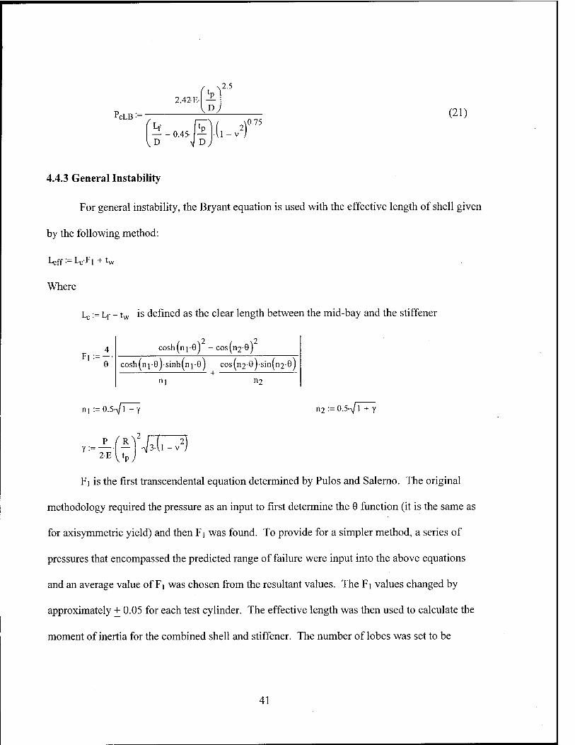
4.4.3 General Instability
For general instability, the Bryant equation is used with the effective length of shell given
by the following method:
Leff.= LcFi + tw
Where
Lc := Lf - tw is defined as the clear length between the mid-bay and the stiffener
4 F,:=--
cosh m ] of - cos(ri2- s)2
cosh(n j •0Jsinh(n ,e) cos(n2 +
•9Jsin(n2
n2
e)
n! --O.S^jT n2: = 0.5-/T + y
y:=- 2-E
^R^
\1PJ ■ffTT)
F\ is the first transcendental equation determined by Pulos and Salerno. The original
methodology required the pressure as an input to first determine the 6 function (it is the same as
for axisymmetric yield) and then Fi was found. To provide for a simpler method, a series of
pressures that encompassed the predicted range of failure were input into the above equations
and an average value of Fi was chosen from the resultant values. The Fi values changed by
approximately + 0.05 for each test cylinder. The effective length was then used to calculate the
moment of inertia for the combined shell and stiffener. The number of lobes was set to be
41

between 2 and 4; the failure pressure was then found without other modifications to the Bryant
formula.
PcGI Etr m M2~ Elcff
W -'+ T w 2 2 + m
R3Lf
Where:
(22)
m:= n- Ls
42

Chapter 5: Experimental Results
The various Classification Societies' design rules were tested against data collected from
experiments conducted by the U. S. Navy in support of submarine design. Each society's design
rules were used to determine the failure pressure and failure mode of each of the test cylinders.
The resulting predictions were then compared to the experimental results. Of primary interest
was agreement between the design rule prediction and experiment on the mode of failure,
followed by the closeness of the predicted failure pressure to the actual collapse pressure.
5.1 NAVSEA Test Cylinders
The test data was provided by the Naval Sea Systems Command submarine structures
unit (SEA 05P2). Four test cylinders were selected that covered the range of examined failure
modes. The cylinder diameter to thickness ratios (D/t) fell between 112 to 198, modeling typical
submarine D/t ratios. Two of the cylinders had internal stiffeners while the other two cylinders
had external stiffeners. All four test cylinders had built-up end stiffeners with a combination of
slightly different spacing and / or larger stiffener dimensions than the uniform field stiffeners.
These end stiffeners were designed to prevent shell yielding in the end bays due to increased
stress levels associated with the boundary conditions. It was estimated that without the end
stiffeners a 4-5% reduction in axisymmetric yielding pressure could occur. None of the end
stiffeners met the classification societies' requirement for a "deep" stiffener. None of the design
rule codes allowed for these variable stiffeners, therefore the non-uniformities were disregarded
and the end stiffeners treated as field stiffeners. The four cylinders are described below.
43

5.1.1 Cylinder l.d
Cylinder l.d was a machined cylindrical shell with rectangular external ring stiffeners.
The material was high strength steel with a yield strength of 80,000 psi. Figure 5 shows the
schematic of the cylinder. The boundary conditions consisted of one end being fully fixed; the
other end had all freedoms fixed except for axial displacement (these conditions conflict with the
design rules assumption of completely clamped ends). External hydrostatic pressure was applied
including axial line load to simulate load on the end plate. The experiment tested the ability of
the design rules to predict elastic shell bucking (Lobar buckling). The experimentally
determined collapse pressure was 633 psi with failure by asymmetric (Lobar) buckling.
Appendix A has the analysis of predicted failure for this cylinder.
Figure 5: Test Cylinder l.d Schematic
4.260 (Typical Spacing) 2.712—?| K- H| -J|
p n iL n ii iL ^-,™
X. u—u—u—Tin—ir^tl
Fr.1 Fr.2 Fr. 3 Fi.4\Fi.5
FT o »
I ^0.750-91
Bulkhead Ring
All dimension« sue inches
Typical Fi ame
44

5.1.2 Cylinder l.f
Cylinder l.f was a cylindrical shell with internal tee stiffeners of welded construction.
The material was high strength steel with a yield strength of 98,500 psi. The boundary
conditions consisted of 4.0 inch steel plates attached with full fixity to the end of the adaptor ring
on the model. External hydrostatic pressure was applied. This test cylinder was used to predict
failure by elastic general instability. There was no experimental elastic collapse pressure;
therefore the critical pressure was calculated by two separate, reliable analysis programs with the
results being 4858 psi (with 3 waves) and 4953 psi (with 3 waves). The test cylinder actually
failed by inelastic general instability at a pressure of 2200 psi. Figure 6 shows the cylinder
dimensions and Appendix B has the analysis of predicted failure for this cylinder.
Figure 6: Test Cylinder l.f Schematic
Acfeplo Ring-
——Detail 'B'.
^c
-p'
k-m|t o IGI-2 SIC 1-2-0
Detail'«
Frames 1 S15
■^z Z7
IGI-2« IGI-2-0
Detail'B'
Frames 2-14
TABLE OF DIMENSIONS (inches)
A B C D E F G H 1 J K L M H P Q R i
45.655 31567 - 2 JIG £.331 — 0.253 — 31.92 — 0265 0305 0263 0.198 0.763 0.762 0263
45

5.1.3 Cylinder 2.a
Cylinder 2.a was a machined cylindrical shell with external tee stiffeners. The material
was high strength steel with a yield strength 65,500 psi. Figure 7 shows the schematic of the
cylinder. The boundary conditions consisted of end closures made of 3.0 inch steel plates
attached to the idealized adaptor ring with full fixity. External uniform hydrostatic pressure was
applied to the model. This cylinder was used by the Navy to predict end bay failure (shell
collapse influenced by end bay design). This is a specific example of axisymmetric buckling and
was used as the axisymmetric model for the classification society rules. The experimental
collapse pressure was found to be 921 psi by axisymmetric collapse in the second bay from the
adaptor ring. Appendix C has the analysis of predicted failure for this cylinder.
Figure 7: Test Cylinder 2.a Schematic
10.64 • 0.903 0.903
fe [email protected] 0)
-5£5&5£JeJ5_5g_ T7
f1 r
t^^a
Adaptor Ring
|(-0.399-3|
~r
0.044 -3 5-
3~f
Typical Frames
|e0.399-5|
X 0.044 -M K-
1T
End Fr «lines
Alt dimensions .ire indies
46

5.1.4 Cylinder 2.c
Cylinder 2.c was a fabricated cylinder with internal ring stiffeners. The base material
was high strength steel with a yield strength of 157,000 psi. Figure 8 shows the schematic of the
cylinder. The shell was cold rolled and fabricated with a deliberate out-of-roundness
imperfection. The frames were built-up. The frame web material was base metal, and the frame
flanges were cold rolled. The boundary conditions consisted of one end being fully fixed with
the other end having all freedoms except axial displacement. External uniform hydrostatic
pressure with an axial end load to simulate end plate loading was applied. This test cylinder was
used by NAVSEA to predict the inelastic general instability failure mode and to model out-of-
roundness imperfections. In the current comparison the out-of-roundness was disregarded. The
collapse pressure was experimentally found to be 3640 psi in 2 circumferential waves in an
inelastic general instability mode. Appendix D has the analysis of predicted failure for this
cylinder.
Figure 8: Test Cylinder 2.c Schematic
11111111111111111111111111111111111 35 34 33 32 31 30 29 28 27 26 25 24 23 22 21 20 19 18 17 18 15 14 13 12 11 10 9 8 7 8 5 A3 2 1
See Detail "A"
h-2 K
—$ £— 0.127
L \t— 1.789 —}| '
0.305
0.127
0.305
TYP
I FR32
Detail "A" FWD. END SIMILAR BUT All dimensions in inches TO OPPOSITE HAIID
47

5.2 Calculation to Experiment Comparison
Table 1 shows the comparison of the classification societies' design rules to the
experimental results. The table displays the calculated failure pressure and failure mode for each
cylinder and the percent difference from the experimental failure pressure (if the experimental
and calculated failure modes are the same).
Table 1: Comparison of Design Rule Calculations to Experimental Results
l.d l.f 2.a 2.C Pressure Mode Pressure Mode Pressure Mode Pressure Mode
NAVSEA
EPERIMENT
633 L 2200 iGI 921 AX 3640 iGI
Analytic
Solution
605
-4.6%
L 2141 AX 876
-5.1%
AX 4080 AX
ABS 605
-4.6%
L 2039 AX 844
-8.8%
AX 4211 AX
PNA 605
-4 .6%
L 1928 AX 815
-12.1%
AX 3864 AX
Germanischer
Lloyd
606
-4.5%
L 2931 AX 1030
12.4%
AX 4567 AX
13A Professional
Summer 605
-4. 6%
L 1994 AX 819
-11.6%
AX 3712 AX
Key: L
AX
GI
e/i
Asymmetric (Lobar) Buckling
Axisymmetric Yielding
General Instability
elastic / inelastic
There is excellent agreement between the experimental data and the calculations for
cylinder 1 .d. The Lobar buckling failure was expected as the slenderness ratio was 201, several
magnitudes greater than the breakpoint of 1.14 between asymmetric and axisymmetric failure.
The agreement between the design rules and the analytic solution calculations was expected as
they all used the same formula to determine the lobar buckling pressure. The calculated failure
pressure was 4% below the experimental pressure. The higher experimental critical pressure was
attributable to the test cylinder being more fully clamped than theorized in the design rules.
48

Cylinder 2.a also generated agreement between the experimental data and the design rule
calculations. The predicted failure mode of axisymmetric yield was confirmed by the
experiment. However there were some significant differences between the predicted collapse
pressure and the experimental failure pressure. All of the design rules, except for the
Germanischer Lloyd, predicted failure at a pressure lower than that experimentally found. The
Germanischer Lloyd calculation over estimated the failure pressure and was the furthest from the
experimental pressure with a pressure 11.8% over the experimental pressure. This failure mode
is the most dependent upon the yield strength of the material therefore a small variance between
the given yield strength and the actual yield strength of the test specimen may have contributed
to the differing pressures predicted by the design rules. All of the design rules use a simplified
version of the methodology presented by Pulos and Salerno [7]. The Germanischer Lloyd and
the modified Professional Summer calculations, perform an iterative operation to find the
pressure, very close to the analytic methodology. The ABS and PNA calculations use single
value equations substituted for the transcendental functions of the analytic solution.
Cylinder l.f failed at 2200 psi experimentally in an inelastic general instability mode.
The experiment was done to test the ability of NAVSEA's computer codes to predict elastic
general instability. A predicted failure pressure of 4858 psi was determined for the elastic
general instability mode. The design rule codes estimated the general instability failure pressure
very well. Table 2 compares the design rules and analytic solution general instability pressures
to the experimental failure pressure. The agreement between the design rules was expected as
they all use the Bryant equation (equation 10) to determine the failure pressure. The only
differences come from the variations in the effective length of the shell for the combined shell
and stiffener calculations and small variations in the radius used in the equation.
49

Of further interest to cylinder 1 .f was that the design rules predicted failure by
axisymmetric yielding at an average of 2206 psi.. As the cylinder actually failed by inelastic
general instability the design code predictions indicate that the two modes of failure are very
close together. This cylinder was very close to failure in multiple modes at approximately the
same pressure (i.e. an identical cylinder of the same dimensions and material may have failed by
axisymmetric yielding vice the general instability depending on the eccentricity of the cylinder
and other small defects). This multiple failure mode condition must be guarded against in real
designs, usually by applying different safety factors to the various modes. [1]
Table 2: Cylinderl.f Elastic General Instability Failure Pressures
DESIGN RULE FAILURE PRESSURE (PSI)
% FROM EXPERIMENT
LOBES
Experiment 4858 3 Analytic Solution 4496 -7.5 3
ABS 4496 -7.5 3 PNA 4496 -7.5 3
Germanischer Lloyd 4651 -4.3 3 13A PS 4460 -8.2 3
Cylinder 2.c failed at 3640 psi in an inelastic general instability mode with 2
circumferential waves. However the design rule calculations all predicted failure by
axisymmetric yielding at an average pressure of 4086 psi. For this cylinder the design rule codes
were not close in predicting the elastic general instability failure pressure. This large
overestimation of the failure pressure can be attributed to the assumption of perfect circularity in
the design codes, whereas the experimental model had a two-wave sinusoidal imperfection of
maximum height of + 0.105 inches. This deliberate out-of-roundness would significantly reduce
the resistance to buckling. Table 3 compares the design rules / analytic solution to the
experimental failure pressure.
50

From Table 3, the axisymmetric failure pressures were higher than the actual failure
pressure but all were within 16% of the experimental result. This closeness between the failure
modes resembles the results for cylinder 1 .f. Further study may be warranted to explore
connections between axisymmetric yield and inelastic general instability.
Table 3: Cylinder 2.c Elastic General Instability Failure Pressures
DESIGN RULE FAILURE PRESSURE (PSI)
% FROM EXPERIMENT
LOBES
Experiment 3640 2 Analytic Solution 8642 137.4 2
ABS 8642 137.4 2 PNA 8642 137.4 2
Germanischer Lloyd 9702 166.5 2 13A PS 8536 134.5 2
51

This page intentionally left blank
52

Chapter 6: Conclusions
The classification society design rules studied are important tools for engineers and naval
architects designing and studying cylindrical structures subjected to external hydrostatic
pressure. The engineer must have confidence that the design code used will provide acceptable
(safe) calculations for his or her structure. This confidence can be assured by comparison of the
calculated failure pressure and mode to that found from experiments. This thesis attempted to
provide that comparison for several of the most used design rules along with a comparison of the
analytical solution upon which most the design rules are at least partly based.
6.1 Comparative Analysis Review
As discussed in Chapter 5, the design rules had mixed results in correctly predicting the
failure mode and failure pressure of the test cylinders. In general all of the design rules and the
analytic solution were in agreement for the specific geometries. For the test cases of failure by
axisymmetric yielding and lobar buckling, the calculated pressures were accurate when
compared against the experimental results. However for the two cylinders that experimentally
failed by general instability, all of the design codes predicted failure by axisymmetric yielding
vice the general instability. The design rules only account for elastic general instability which
will occur at a higher pressure than the inelastic general instability. For cylinder 1 .f the design
codes calculation of the elastic general instability mode failure pressure was very accurate, but
for cylinder 2.c the calculated failure pressures were all greater than 100% over the experimental
pressure. The majority of the pressure differentials for 2.c can be attributed to the built-in non-
circularity in the test cylinder.
53

6.2 Agreements and Differences
In this thesis there were thirty failure pressures calculated (five failures for each of four
test cylinders and five general instability pressures each for the two cylinders that failed by
general instability) with design rule / analytic solution agreement on 33% of the pressures. The
other twenty pressure calculations varied from over 30% to less than 1% different.
The pressure calculations that were in agreement were generated from the use of the same
equation and same dimensions for most of the asymmetric buckling and elastic general
instability calculations. For the asymmetric buckling predictions, ABS, PNA, and the MIT 13A
Professional Summer calculations use the same equation as the analytic solution. This equation
was independent of the number of circumferential lobes in the failed part of the shell. For the
general instability cases, the ABS and PNA calculations agreed with the analytic solution. These
three codes used the same effective length (Lc = frame spacing) and the assumption that the
radius of the combined shell and stiffener was the mid-plane radius of the shell.
The difference between calculations can be accounted for individually: The
Germanischer Lloyd code for asymmetric buckling used an iterative process that was dependent
of the number of lobes in the failed cylinder; however the failure pressure was still within a tenth
of a percent of the other calculations. The predictions for elastic general instability were also
generally close. The Germanischer Lloyd and MIT 13A Professional Summer codes used
different assumptions for Le than the other codes, which gave predicted failure pressures slightly
different than the base general instability equation (equation 10). The largest variations between
the codes were generated for the axisymmetric yield mode. All of the codes used simplified
variations the analytic solution developed by Pulos and Salerno. These variations in the shell
yielding pressure come about due to the different simplifications made in the codes.
54

6.3 Applications of the Models
The various design rules studied are promulgated to ensure safe design of cylinders for
use under external pressure conditions. This safe operation requires an almost absolute certainty
that the design will not fail under the worst anticipated condition (many theories and practices
exist on risk based design and the use of safety factors). The comparison of the design rules to
an analytic solution, analysis tools (MIT 13A Professional Summer and SNAME), and to
experimental results allows a designer to have a good idea of how a particular cylinder design
would be evaluated by each entity. This comparison ability would be useful in judging the initial
feasibility of a design and also would be useful in applications where a design would be subject
to more than one classification society.
The comparisons in this thesis should in no way be used as a detailed design tool for the
subject cylinders. After an initial design is compared and judged to be adequate, much more
rigorous analyses must be used to ensure a safe design. These advanced analyses should include
finite element methodology and other tools that can look at local stresses instead of generalized
stresses in the shell. These higher order analysis tools can account for material differences,
geometric eccentricities (out-of-roundness and other along the shell), varied spacing and sizes of
stiffeners, and actual construction factors such as heat effected zones around welds, and
bulkhead effects. Another important area that is addressed by other parts of the design rules but
not studied here is that of shell penetrations. These discontinuities in the shell are very
susceptible to stress concentration and must be reinforced to prevent failure at pressures lower
than that predicted for a continuous shell.
55

6.4 Further Areas of Study
There are several areas that require further research to completely understand the result of
the above analysis. The area most evident in need of more study is the failure of the cylinders by
inelastic general instability. While some work has been accomplished on this phenomenon, most
of the work is either classified by government entities or is empirical data. As part of the
research into the inelastic general instability should be a detailed analysis of interactions /
relationships with axisymmetric yield. As found from the experimental cylinders that failed by
inelastic general instability, the design codes and analytic solution predicted failure by
axisymmetric yield of the shell at pressures close to the actual failure pressures. These
comparisons suggest that at least the two modes are very close together and may have some
interaction.
There are many other classification societies that produce design rules for stiffened
cylinders and other geometries. These societies include the American Petroleum Institute (API),
NORSOK and Det Norske Veritas (Norway), Lloyd's Register (United Kingdom), Registro
Italiano Navale Group (RINA) (Italy) and several others. These additional design rules could be
compared against the existing test cylinders as well as all of the design rules should be compared
against more experimental data.
Finally, the base methodology can be expanded to include other geometries such as
spheres, hemi-spheres, cones and toroids. The classification societies address most of these
forms which can be found as the end closures for most submersibles and other pressure vessels.
These more complex geometries present more challenging analytic solutions and are in general
harder to manufacture. Experimental data is scarcer; therefore finite element models may be
needed to generate comparisons.
56
References
[1] Society of Naval Architects and Marine Engineers. 1967. Principles of Naval Architecture. New York: The Society of Naval Architects and Marine Engineers.
[2] American Bureau of Shipping. 1990. Rules for Building and Classing Underwater Vehicles, Systems and Hyperbaric Facilities. New York: American Bureau of Shipping
[3] Germanischer Lloyd. 1988. Rules for Underwater Technology. Hamburg: Germanischer Lloyd
[4] Society of Naval Architects and Marine Engineers. 1990. Submersible Vehicle Systems Design. Jersey City: The Society of Naval Architects and Marine Engineers.
[5] Massachusetts Institute of Technology Program 13A Professional Summer. 2001. Submarine Design Trends. Unpublished
[6] Nash, William A. 1995. Hydrostatically Loaded Structures: The Structural Mechanics, Analysis and Design of Powered Submersibles. Tarrytown: Pergamon Press.
[7] Pulos, J.G., and Salerno, V.L. 1961. Axisymmetric Elastic Deformations and Stresses in a Ring-Stiffened, Perfectly Circular Cylindrical Shell Under External Hydrostatic Pressure. David Taylor Model Basin Report 1497.
[8] Kendrick, S. 1965. The Buckling Under External Pressure of Ring Stiffened Circular Cylinders. In Transactions of The Royal Institution of Naval Architects VM1-15 vl07 139-156. United Kingdom: Royal Institution of Naval Architects.
[9] Ross, C. T. F. 1965. The Collapse of Ring-Reinforced Cylinders Under Uniform External Pressure. In Transactions of The Royal Institution of Naval Architects VM1-15 vl07 375-394. United Kingdom: Royal Institution of Naval Architects.
[10] Avallone, Eugene A. ed. and Theodore Baumeister III, ed. 1996. Marks' Standard Handbook for Mechanical Engineers. New York: McGraw-Hill.
[11] Will, William. 2002. Private Conversations. Washington, D.C.
57
This page intentionally left blank
58

Appendix A: Codes for Test Cylinder l.d
59

AMERICAN BUREAU OF SHIPPING
Rules for Building and Classing Underwater Vehicles,
Systems, and Hyperbaric Facilities
Definitions
ksi:= lOOOpsi
E := 3000(ksi Modulus of Elasticity
v := 0.3 Poisson's Ratio
o := 80000psi Yield strength
Shell Parameters
Ls := 4.266n Distance between stiffeners
Lc = 22.488in Distance between bulkheads
R = 8.007in Mean radius of shell
t = 0.081 in Thickness of shell
R •= R + - Outer radius of shell o 2
D0 := 2R0 Outer Diameter of shell
Ring Stiffeners
tw:=0.l38n thickness of web of ring stiffener
depth := 0.57in height of ring stiffener
b := tw faying width of stiffener (from P&S for I beam stiffener)
bf := o.Oin breadth of ring stiffener
b2 := bf - tw breadth of ring stiffener minus the web thickness
60

d := O.Oin ring stiffener flange thickness
Lu := L -1 Unsupported spacing between stiffeners
L:=ma>(Ls,Lb)
L=4.266in
.5- tw-depth +b2d
V depth + b2-d first centroidal height of ring stiffener
cj = 0.285in
c2 := depth - cj second centroidal height of ring stiffener
c2 = 0.285in
h := cj - d distance from centroid of ring stiffener to nearest edge of flange
R^ := R + .5-t + c2 radius to centroid of ring stiffener
Rj = 8.332in
A := (t • depth + b2-d) cross-sectional area of ring stiffener
As = 0.079in
Ir:=|^)(bf-cl3-b2-h3 + Vc23 moment of inertia of ring stiffener about its centroidal axis
Ir=2.13x 10 3in4
Rf-:= R + .5-t + depth Radius to tip of the stiffener
Rf = 8.617in
Combined Plate and Ring Stiffener
effective length of shell plate ^1.5•^/R4A
Le := min . 0.75L. , V s J
61

Le= 1.208in
Ap:=Lt area of effective plate
A '= A + A sp '^p T ns area of plate and ring stiffener
Hc := depth + t height of combined plate and ring stiffener
Hc = 0.054ft
B, := L - tw plate length minus the web thickness
c]c:=.5{ twHc
2 + Brt2+b2d(2Hc-d)
twHc + B,t + db2 neutral axis of combined plate and ring stiffener
from outer fiber of plate (R0)
c,c = O.lOlin
\ := R - .5t + clc radius to centroidal axis of combined ring stiffener and shell
Re = 8.067in
'-3 .L'lc3 " B,(clc - l)3 + bf-(Hc - c,cf - (bf - tw).(Hc - c|c - d)3
moment of inertia of combined plate and shell
Ie = 0.009in4
General Equations
M:=L
Rt
M = 5.297
e:=[3(,-v2); •M
62

6 = 6.809
Q:=
Q = 3.405
N:= cosh(2Q) -cos(2Q)
sinh(2Q) + sin(2-Q)
N = 0.997
G:=2 (sinh(Q)-cos(Q) + cosh(Q)sin(Q))
sinh(2Q) + sin(2Q)
G =-0.081
H:= sinh(2Q) - sin(2Q)
sinh(2Q) + sin(2Q)
H = 0.998
Inter-Stiffener Strength (6.19.1)
1) Inter-stiffener strength equations
This equates to axisymmetric buckling
A:=A. Effective area of plate and stiffener (External stiffeners)
A = 0.073in2
A- 1
F:=
•G ■J
A + tw-t + 2N-t-L
F = -0.027
ay- t
R
1 -F yield pressure at midbay and midplane of cylinder
63

P = 787.9psi
This corresponds to Lobar buckling
2.42- E- Pm:=
2R
(.-.') 2R l2R
von Mises buckling pressure for a cylinder
P = 604.9psi
Maximum allowable working pressure for inter-stiffener strength
P P m ._ m Pc:= 2
1 f — < 1 py
■V f
1 P ^ y
2P
h . Pm if >3
py
Pm
py = 0.768
Pc = 302.4psi
p • - raits •" = Pc- .8
if 1<—<3 py
aits 242psi
64

2) longitudinal stress
Limiting pressure corresponding to the longitudinal stress at stiffeners reaching yield. No direct
correlation to major failure modes
y:=
A-l 1
A + tw-t + 2-N-t-L
e
pi:= 2-cyt
R 1 +
( 12 ^^ •y-H
vl -v J
P, = 732.7psi
P„k := Pi.67 Maximum allowable working pressure for longitudinal stress
pals = 49088Psi
b Overall Buckling Strength (6.19.5)
K:=- 7T-R
n:= 1
A2(n) := n - 1
AjCn)- X
f
A2(n) + V 2 ̂
(2 3 •\n + A. /
E.t EIe-A2(n)
R R3L
65

Given
n >2
n2 := Minimiza pn j ,n]
n2 = 3.109
n must be an integer
n2im:= round (n2,0)
"2int = 3
12first
n2first = 2
n2jnt100 if n2int=l
n2int ~ ' otherwise
12prime'
f n2f.rst X
n2int
n2int+1
n2int+2
12prime]
Pn2:=
Pn2 =
'Pnlfn2prim^)
Pnlfn2prime,
Pnl('n2prime2
Pnlfn2prime3
( 3^ 5.127x 10
1.522x 10³
1.974x 10³
psi
1,3.022 x 10 j
Pn := min(Pn2)
66

p_ = 1522.3psi
Paol:=Pn-5
Paol = 761.131psi
Summary
Axisymmetric Buckling
Py = 787.9psi
Lobar Buckling
Pm = 604.9psi
General Instability
pn = 1522.3psi
n2int = 3
67

Germanischer Lloyd
1988 Edition
Chapter 2 - Submersibles
MPa:=106Pa ksi:=103psi
General Definitions
E:=3000(ksi
Lj := 4.26än stiffener spacing
L3 := 22.488n length of cylinder between bulkheads or lines of support
s := .08lin thickness of shell
R := 8.002n radius to centerline of shell
v := 0.3 Poisson's Ratio
k := 80-ksi minimum yield stress of material
Stiffener Dimensions
ef := o.Oin flange thickness
df := o.Oin width of flange from web to edge of flange
b2:=2-df
dw := 0.57in Height of web
ew:=o.l38n web thickness
b := ew width of stiffener ring in contact with shell
A j := ef(evv + 2df) + ew-dw cross-sectional area of stiffener ring
A, =0.079in2
68

"stiff :=dw+ef
Hstiff=0.57in
'1 -= 1 ew "stiff +b2ef
2 ewHstiff+b2ef
cj =0.285in
c2:" "stiff ~cl
c2 = 0.285in
h2 := c, - ef
h2 = 0.285in
(ew + 2df)cj -(2df)h2 + ew-c2 Centroidal Moment of inertia of ring stiffener
Ij =2.13x 10 3in4
e := c2 + .5s distance from stiffener centroid to center of shell
e = 0.325in
Effective Stiffener and Shell
Letest :=b+V2Rs
Le:= Letest if Letest - Ll
Li otherwise
Le= 1.277in
2 3 A,e Les
1 .- I li + e A, J 12 1 + —-
Le-s
L = 6.92x 10 3in4
Effective length of shell (eqn 45a,b)
Moment of Inertia of combined plate and shell
69

Hstiffc:= Hstiff + s Total height of stiffener and plate
Hstiffc = °-651in
dj := s
bsl:=Le-ew
1 ewHstiffc + b2ef +bsls(2Hstiffc-s) clc:= 2 ewHstifrc
+ b2ef+bsrs
c]c = 0.47in
c2c:=Hstiffc_clc
c2c = 0.181in
R0 := R - .5s + c2c radius of stiffener ring centroid including effect of Le
R0 = 8.I48in
R2 A := A, Modified area of stiffener ring
«o2
A = 0.076in2
el:=c2c+5s
e, =0.222in
70

2.4 Asymmetrie Buckling (Lobar but not named this)
TtR
Li
n := 2 initial guess
R trt\ ■
( 2 ^
w I "2 2f 2 , , A2
s -In - 1 + ^.j 1 1
2( 2) 12R -U -v /
Pn](n).- 2 , c, 2
n - 1 + .5-Xj
I >s-ßnl(n) Pn](n).-
R
Given
n>2
n := Minimizap i ,n)
n0 = 10.612 n must be an integer
ngint:= round (ng,ö)
ngint = ''
"gfirst:" ngjnt-100 if ngint=l
"gint"1 < Dtherwise
"gfirst = 10
gpnme'
^ "gfirst ^
"gint
"gint + l
V"gint + 2y
gpnme
(\0^
11
12
V13y
71

Pn2:=
Pnl h gpnme0 )
gpnme Pnl(n
Pnl^gprimeJ
Pnl^gprimeJ
Per:= min(Pn2)
pcr = 605.9psi
3.3.3 General Instability
L:=U
71-R
X2= 1.119
ßn2(n):=
P0(n) :=
P](n):=-
(^n2 - 1 + 0.5-X22jf n2 + X7
Esßn2(n)
R
(n2-l).E,p
RoLl
Pnla(n):=P0(n) + Pl(n)
n:=2
Given
n>2
n2:=Minimiz^pnla>n)
72

n? = 3.247 n must be an integer
n2int:=round(n2>°)
n2int = 3
12prime-
^2int-^
n2int
n2int + '
vn2int+2y
Pnlaf n2prime.
Pg2:=
Pnlaf n2primej
Pnlaf n2prime,
Pnlaf n2prime,
Pg:=min(pg2)
pB = 1244psi
/
PR2
5.022x 10
1.244x 10
1.452x 10
V2.187x 10 )
psi
2.6 Symmetric Buckling (axisymmetric)
More Definitions
For Elastic-Plastic Region (Eqns are in the program)
Es := E Secant Modulus = Young's Modulus for elastic region
Ej^E Tangent Modulus = Young's Modulus for elastic region
v := v Poissons Ratio, elastic-plastic; = Poisson's ratio in elastic
1^7] s2-R2
shape factor
73

a = 0.063— mm
C5:= = a-L] calculation factor for symmetric buckling
C5 = 6.809
Pact 2s E . .
:= . critical pressure, elastic, calculation factor 1 dM
R2J3.(,-v2)
Past = 3716.21 lpsi
C5: = a-L] calculation factor for symmetric buckling
C5 = 6.809
G:= p
Past
C6: = — J\ -G 2
C7: = — J\ + G 2
C8: = C5C6
C9: = c5-c7
F. • 4 cosh(Cg) -cos(c9)
rl ' C5 cosh(Cg)sinh(Cg) cos(c9)sin(c9)
c6 c7
cosh(Cg)-sin(c9) sinh(CgVcos(c9)
F-, - C7 C6
r2- cosh(Cg)sinh(Cg) cos(c9)sin(c9j
c6 c7
74

cos(Cg)sin(C^j cosh (CgVsinm Cgi
F,:= 2 cosh(Cgjsinh(Cgj coslC^jsirnCpj
cosh (Cglsinl Cn) sinhl Cgjcosf Co)
2 cosh(CgVsinhfCg) cos(Co)sin(C0J 1 -v
C,
C
1 2y s-Li
10- A b + h sLi Li
( O
C 11 0.91
1 -v
-p-R
CTx:=aoi- + cio'cirF4
a<f>:= ao{1 - C10'F2 + vC10Cl 1F4)
axi:=ao| --ciocirF4
ax=-3.286x 10 Pa
a(()l:=Go-( 1 -C10"F2~vC10CllF4)
a± = -6.(>5\x 10 Pa
K0
C*
.8k = 64ksi Determination factor (if>.8k then must use Et, Es, etc)
75
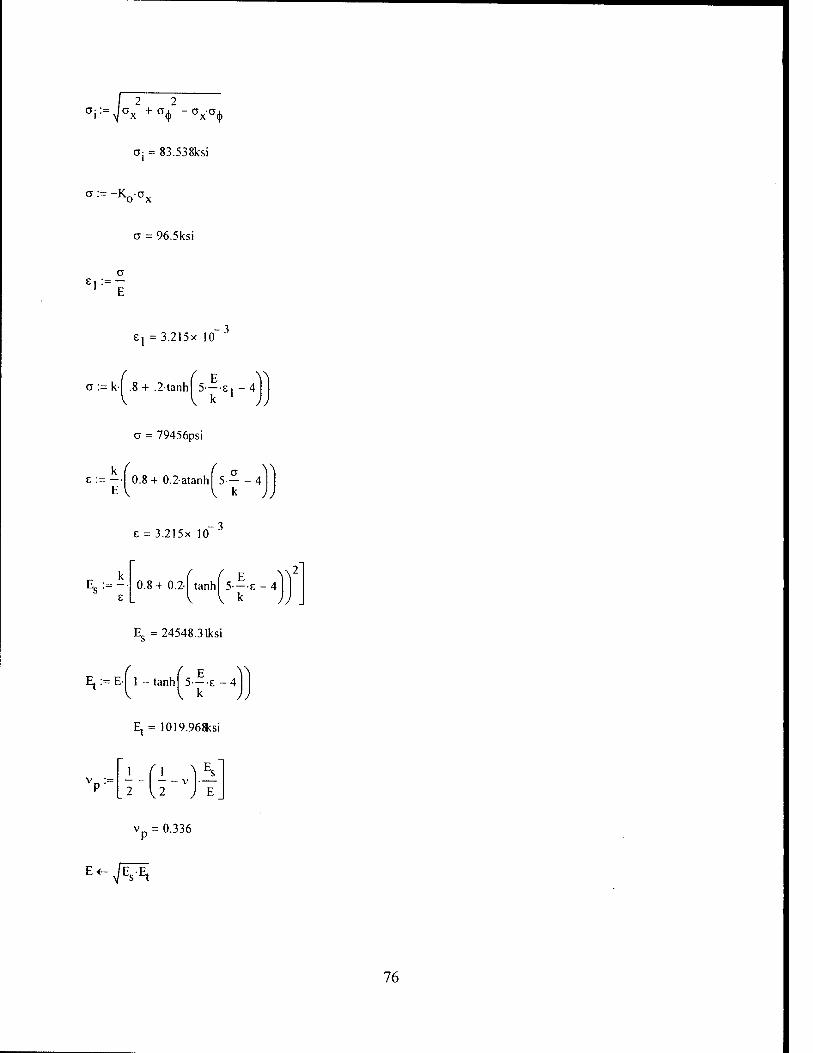
°i:=V°x2 + a4> -ax°<|)
Oj = 83.538ksi
u := -Koüx
a = 96.5ksi
E, :=-
E, =3.215x 10
:=k- .8+ .2tanh 5—E, -4 1
a = 79456psi
£:=-■ 0.8+ 0.2atanh 5 4
E = 3.215x 10
E 0.8+ 0.2-| tanh| 5—E -4
Es = 24548.3 lksi
Ej :=E[ 1 -tanh| 5—E - 4
Et= 1019.968ksi
2 12 J E
vp = 0.336
■sj^s'^x
76

2.s2-Es
Paa ■ —
^('-vp'j
K,:= (l-K0 + K02)
H,
4|l-vp j-Kj
H2--=[(2-vp)-(l-2-vp}K0-]
Hp= 1 + H4- H2 -3-^1 -vp
C ( H2.H3.H4^
3'- 1 + vpHl
C3 = 0.068
C2:=
' 2 > H3 H4
C2 = 0.049
Cj:=
2 > H2 H4
1 Hi
Cj = 0.897
C0:=
2 2 crc2-vP-
c3
2 ]-Vp
c0 = c .221
77

a, :=
4
3-
2
A s2-R2
trial := a,L,
trial = 1.068
m:= 1
m tria!2:= J— (m + 1)
trial2= 1 iterate on m until trial is < trial2
Pm:~ Paa'C0
pm = 923.8psi
p = 924.0psi
a,hA , ' f *-m ^ UarLiy
failure pressure
iteration point - change pressure until pm = p
Summary
Axisymmetric Buckling
pm=923.8psi
Lobar Buckling
pcr = 605.9psi
General Instability
Pg=1244psi
78

Society of Naval Architects and Marine Engineers
Submersible Vehicle Systems Design (1990)
ksi:= lOOCpsi
Input Section
Lf := 4.266n Length between frames
L. := 22.488n Length between bulkheads
R := 8.00^n Radius of cylinder to centerline of shell
t:=0.08lin shell thickness
RQ := R + .5-t radius to outside of shell
RQ = 8.047in
E := 30000ksi modulus of elasticity
a :=80ksi minimum yield stress of material
H ■= 0.3 Poisson's ratio
Ring Stiffeners
t := 0.l3Sn thickness of web of ring stiffener W
depth := 0.57in total height of ring stiffener
bf := O.Oin breadth of ring stiffener
d := O.Oin ring stiffener flange thickness
b7 := bf -1 breadth of ring stiffener minus the web thickness
79

c, := .5-
2 2\ tvvdepth + b2-d
first centroidal height of ring stiffener tw- depth + b2d
C] =0.285in
c2 := depth - c, second centroidal height of ring stiffener
c2 = 0.285in
h := cl ~ d distance from centroid of ring stiffener to nearest edge of flange
h = 0.285in
R,. := R + .5t + c2 radius to centroid of ring stiffener
RT=8.332in
Ar:= (vdePth + b2-d) cross-sectional area of ring stiffener
Ar = 0.079in2
lr:=UJ^bfCl _b2'h +tw'c23J moment of inertia of ring stiffener about its centroidal axis
Ir=2.13x 10~3in4
Combined Plate and Ring Stiffener
area of effective plate
area of plate and ring stiffener
height of combined plate and ring stiffener
plate length minus the web thickness
V = Lft
Asp :=Ap + Ar
HC:= = depth + t
B,:= Lf-(w
80

clc:=.5| twHc
2 + Brt2+b2-d.(2-Hc-d)
twHc + Brt+db2
neutral axis of combined plate and ring stiffener
from outer fiber of plate (RO)
clc = 0.lOHn
R := R - .5t + c, radius to centroidal axis of combined ring stiffener and shell
Rc = 8.067in
L:=- 3 L
Lf clc3 - Bl(clc - *)3 + bf(Hc - c]c)3 - (bf - tw)-(Hc - clc - d)3
moment of inertia of combined plate and shell
Ie = 0.009in4
Axisymmetric yielding
B:= V1
Ar + twt
B = 0.124
0 := 10-|j2-U - \?)_ f T„ \
V2-Ry
50-t
R
9 = 6.809
N:= cosh(e)-cos(e)
sinh(e) + sin(e)
N = 0.997
ß:= 11-N
50-
f 2 ^^
Ar + t„ ,-t V r w ) R
ß = 1.126
81

H:=
( (*\ 3-sinh —
\2J cos| — I + cosh
fa\ fQ\ — -sin
sinh(e) + sin(e)
H = 0.105
> R Pv: y '0.85-B
1 + H- 1 + ß
py = 781.382psi
Lobar Buckling
Pb:= 2.42 E
2)
t
2R
r _!t - 0.4S|
' > i2
[_2-R \ .2-R, ) \
Pj, = 604.9psi
General Instability
7tR
Lb
n:= 1
Pcrl("):=V7 E-t
R 2 , m
n - 1 + — 2 /
(n2-,). EL
(2 2)2
•\n + m } R Lf
Given
n> 1
82

n2 := Minimiza pcrj,n)
n2 = 3.109 n must be an integer
n2jnt:= round (n2,0)
n2int = 3
12first -= n2inf100 if n2jnt=l
n2int _ ^ otherwise
12first:
2prime'
f n2first A
n2int
n2int + ]
Vn2int+27
Pcr2:
-ZT'
'PcrljSprime^
Pcr/^prime,
Pcrlf ^prim^l
Pcrlf ^prime^
in(Pcr2)
pcr = 1522.3psi
Summary
Axisymmetric Buckling
p = 781.4psi
Lobar Buckling
Pfr = 604.9psi
General Instability
pcr = 1522.3psi
83

MIT 13A Professional Summer Submarine Design Trends
PROGRAM TO COMPUTE SUITABILITY OF SUBMARINE DESIGN PARAMETERS.
Ref: "Hull Material Trade Off Study", D Fox, Jan 94
ksi= lOOOpsi
Global Variable Inputs:
e = 0.Oin Eccentricity
Material:
GV = 80000psi yield stress of mat
E = 3000(ksi young's modululs
v =03 poisson's ratio
Geometry:
R = 8.oo^n shell radius
DH2R shell diameter
Lf = 4.266n frame spacing
Ls = 22.488n bulkhead spacing
tp = o.08iin shell thickness
tf = o.Oin flange tickness
wf HE o.Oin flange width
tw = 0.i38n web thickness
hw s o.57in web height
84

Compute areas:
R, ■= R + — Frame Radius 2 .
Rj = 8.047in
Af := tf wf Frame flange, web area
A\v :_ t\V'h\y
A := Af + Aw Frame Area = Flange + Web
A = 0.079in2
PARTI SHELL YIELDING
Von Sanden and Günther (1952)
PNA Section 8.4
twtp
A + tw-tp Area ratio
B = 0.124
9 :=Lf
(R-.p)2 . Slenderness Parameter
9 = 6.809
N:= cosh(e)-cos(e) sinh(e) + sin(e) Deflection coefficient
2-N
A + tw-tp ,-U2) 0.25 f Frame flexibility parameter
ß = 1.126
85

i -- 2)
B
1 + ß Frame deflection parameter
r =0.341
sinh
HM:=-2- •cos| — I + cosh I (B) .(B
— sin — \2J \2
sinh(e) + sin(e) Bending effect (mem)
HM =0.081
HE:=-2- f ^0.5 sinnl - lcos| *\ (*\ f — - cosh — sin
11 ill I C Vl -v' j
HE = 0.085
sinh(e) + sin(e)
2 Bending effect (bend)
K:=
Peri:
sinh(e) - sin(e)
sinh(e) + sin(e) fy «- Oy
P0 <r- 1 Psi
Pj <- 1000 psi
P2 <- 2000 psi
delta <- 5 psi
limit <- 1 psi
conv<- 1 psi
j^0
while j < 20
for i e 0 2
-P;R
lp
-P.R I«6i< ~[l + r.HM-vHEi]
-PR , « —'05 + r-Hpi
-P.R i< —'0.5-r-HEi
°<Mfo ' -PR
l
-P-R l
i -r-
l-r
1 + V 3 "\
0 5
/
1 - v
1 - v
( 3 ^3 .]
. 2 \1 - v )
Bending efffect near frame
86

-P.-R i
1 -r- tp
1 - V
°xxfb '
°xxfi<-
-P.-R l
-P.-R
o.5 - r 3 ^
1 - v
0.5
0.5
■K
l-v2y
■K
0.5 + r- ( 3
1 - v
0.5
-K
' sy •e-
' °<t>t>sc>
°iM6i
ü xxso
° XXSl
c xxfo
\ a xxfi /
o 1 <- a syo
° 2 *" ° sy2
f3*-fsy5
° 4 <- a sy7
"SYM ' f 2 2~) J
f 2 2V ^03 - o3ct 4 + a 4 J
a sy <— max °SYM
shel •
dav <
^SYF /
stress. <— a sy
test- <— If y — a syi
test-.
conv
test,
break if stress- - fy < limit
PQ <- P. if shel- dav > 0
P2 <- P, if shel dav < 0
P <— P + M ^ r0 +
j<- j+ 1
lP2 - P0>
ouV
r
87

Perl 801.682
14
Pcrit - Perl -'PS'
Peril = 801.7psi
PART 2 LOBAR BUCKLING
Windenberg Approx of Von Mises (1933)
Assumes n lobes = Pi*D/L
Collapse pressure:
■t x2.5
2.42-E-1 —
PeLB: Lf ft] ( if75
0.4S — Ul -v ) D 4 D )
PeLB = 604.9psi
PART 3 GENERAL INSTABILITY
Corrected Bryant Formula (1954) for better model test correlation
Pressure loading is:
P:=pgDtSFgi
P = 6697.99psi
Compute effective frame spacing:
2 . _P_[ _R
r_2EltP '^T?)
y = 1.802
Compute clear length:
88

LQ:- Lf tw
nj := 0.5-^1 -y
nj=0.448i
Web thickness:
T>2 := 0.5-y/l + y
n2 = 0.837
4 coshmj »f - cos(n2 of cosh(nj •6Jsinh(n
"1
,-e) cosfn 2-GJ-sin(n2
n2
e)
Fj = 0.23
must be less
than 1.00
F1 is almost a linear decreasing function for pressures from 1 to 2000 psi with an average value
of 0.27. This will be used in the following analysis as the pressure is the unknown and therefore
the above equations cannot be directly used.
F! := 0.27
Leff:=Lc-Fl + *v Effective shell plate length:
Leff = 1.253in
Theoretical critical lobe number values are:
i:= 0..2
3
v4y
Aeff := Leff tp
Circumferential Lobes
Effective plate area
89

Aeff = O.lOlin
m:= 7i-
Ls Longitudinal Lobes
m= 1.119
'hw + tf^
yna:
V 2 Af
, 2 Acff
Aeff + Aw + Af Frame-plate neutral axis (ref web centre+ toward
flange):
yna =-0.183m
Uses Parallel Axis Theorm: Icor = I + Ad2
Moments of inertia for plate,flange,web:
Lefftf
12
Iw := twhw"
12
If:= Wf tf
12
'pcor := !p + Aeff f tp + h\v
, 2 + yna
nvcor:_ I\v + AW'(yna)
( H + K A
Ifcor := If + Af yna V 2 j
Total:
90

leff :_ Ipcor + Kvcor + 'fcor
. 4 Ieff = 0.007in
The critical Elastic General Instability pressure is:
&t„ PcGI. :=
m M2~ •E-Ieff
' R / \2 , m / \2 2 H -1+TIH +m.
2 R3.Lf
Min Pressure:
r
PcGI =
5.035x 10
1.278x 10 psi
U.516X 10 )
PcGI := min(PcGl)
PcGI = 1278.1psi
Summary
Axisymmetric Buckling
Peril = 801.7psi
Lobar Buckling
PcLB = 604.9psi
General Instability
PcGI = 1278.1psi
3
91

Analytic Solution
Definitions
ksi:= 6.894757106Pa
E:=30000<si Modulus of Elasticity
R := 8.007m Radius of cylinder to centerline of shell
D:=2R Diameter of cylinder
o := 80ksi Yield strength
L:=4.26än Length of supported cylinder
Lj, := 22.488n Distance between bulkheads
(.1 := .3 Poison's ratio for Fe/Steel
t:=0.081in Shell thickness
Ring Stiffeners
tw:=0.138n thickness of web of ring stiffener
H:=0.57in height of ring stiffener
b:=tw faying width of stiffener (from P&S for I beam stiffener)
bf:=0.0in breadth of ring stiffener
b2:=bf-»w breadth of ring stiffener minus the web thickness
d:=0.0in ring stiffener flange thickness
4)nash := L - bf distance from flange edges
92

cj:=.5. y H2 + b2-d2
twH+b2d ;
first centroidal height of ring stiffener
cj =0.285in
c2:=H-C] second centroidal height of ring stiffener
c2 = 0.285in
h := Ci - d distance from centroid of ring stiffener to nearest edge of flange
h = 0.285in
Rr:=R+ .5t + c2 radius to centroid of ring stiffener
Rj. = 8.332in
Ar := (tw-H + b2d) cross-sectional area of ring stiffener
Ar = 0.079in2
ML 3 , ,3 3 Ij. := - •( bfcj - b2h + twc2 I moment of inertia of ring stiffener about its centroidal axis
Ir = 2.13x 10 3in4
Aeff:=Ar' effective area of stiffener eqn [24a] from P&S
Aeff = 0.076in
A eff a := ratio of effective frame area to shell area eqn [62] P&S L-t
a =0.219
ß := - ratio of faying width to frame spacing eqn [62] P&S
ß = 0.032
93

Combined Plate and Ring Stiffener
Ap := Lt area of effective plate
AsP := AP + Ar area of plate and ring stiffener
Hc := H + t height of combined plate and ring stiffener
Hc = 0.054ft
Bl:=L-»w plate length minus the web thickness
clc:=.5i twHc
2 + Brt2+b2d.(2.Hc-d)
twHc + Bj-t + db2 neutral axis of combined plate and ring stiffener
from outer fiber of plate (R0)
clc = O.lOlin
Rc := R + .5-t + c]c radius to centroidal axis of combined ring stiffener and shell
Rc = 8.148in
L:=- ,Lclc3 - Bl(c,c - t)3 + bf(Hc - c]c)3 - (bf - tw).(Hc - c,c - d)3]
moment of inertia of combined plate and shell
le = 0.oiin4
Buckling of unreinforced shells
von Mises bucking pressure:
n:= l
guess at number of waves around the circumference
94

Purl(n):= \ — E-t
R 2 [ n-R
n + .5- / J
2 n +
7I-R
L
12- (.-
-i2
2 n +
7tR
Given
n> 1
nj :=Minimiz^pur],n)
nj = 10.594
n must be an integer
n]int:= round (nj,0)
nlint=11
1 prime'
"lint"1
"lint
nlint+ l
vnlint+2y
Purlf "lprime.
Purl
Purl "lpri prime.
Purl( "lprime.
V Purl "lpri prime.
Pur := min(Purl)
pur = 607.94^si
95

Axisymi netric Buckling
P cab := y <-0
] im il <-— 1 0 p si
t est <— 0 p si
con v <— I p si
j «- o wh i le j£20
f
Y
) L
i i *- j-V' -i
r, 2 <_ -L.^J] +
e <-^3-(i - n' VRM
4 cosh (r| j -6 j -COS(TI2-0)
0 cosh (r\ ,-eVsinh try , e) c o s (r\ 2 -0)sin (ri 2 O)
ii n2
cosh(r| | e)sin(r| j-6) sinh(r| |<oYcos(r| 2-6)
r , n 2 71 ' cosh(n |0)sinh(ri (o) COS(T| 2-0Vsin(r| 2-0)
1 1 n 2
cos(r) 20)sin (ri 2-0) cosh (r| | eVsinh (r| , ö)
^2 n i r,< 1 3
. 2 ■vj 1 - n
cosh(r| |OVsinh(r) |0) cos(r) 2'0)sin(ri 20)
ni n 2
cosh(r) |-e)sin(iT 2-0) sinh(r) |-eVcos(Ti 2e)
n 2 il 1 r . 1 3
J i - u2 C05h (71 re)sinh (^ re) cos(ri 2-o)sin (IT 2 e)
^ 1 ^2
.. o- « + ß +
"1 — ex 2 )
(l-ß)-F,
denom 1 <- A F22+F2.F4.(, -2,).( I °9' ) + F4
2.(,-M+,2).f 0" ^
L U i - M2 J I ■ - n2 JJ den o m 2 <— [ — H—ra
'AT) PcJ (3
/— + denom 1 - denom 2
break if |p cj - test 1 < Urn it
^!gU,.(-*')!£)' test <- p c2
j <- j + 1
P c2 out <
u c 0 n v
out ( «- j
0 ul
96

Pcab 885.4
Paxiy^Pcab.'P5'
paxiy=885.4psi
Asymmetric Collapse (Lobar buckling)
Windenberg Approx of Von Mises (1933)
Assumes n lobes = Pi*D/L
PcLB:=
2.42EI —
2.5
f- vD
m ( 2)°-75 -0.45 — U -n /
PcLB=604-9Psi
General Instability of shells and rings
^:= 7T-R
n:= 1
Et PcGl(n):= — —
Given
(n2-lW
2y („Wf R'.L
n> 1
r^ := MinimizapcQj,n)
n7 = 3.109 n must be an integer
97
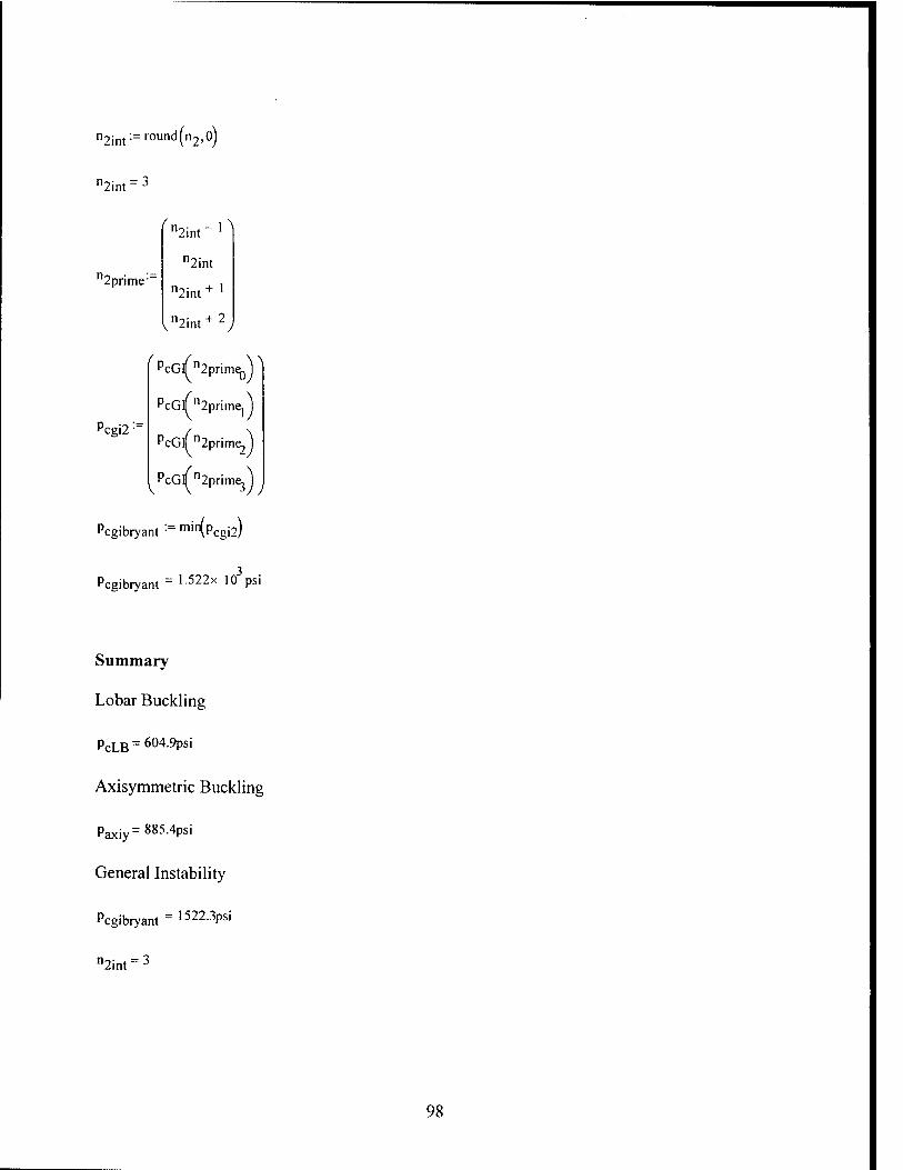
n2int:=round(n2>0)
n2int" 3
12prime-
'n2int-]
n2int
n2int + '
vn2int+2
cgi2 •■
/PcGlTn2prim^V
PcGlTn2prime1)
PcGlfn2prime2")
PcGlfn2prime;")
Pcgibryant := min\Pcgi2)
3 Pcgibryant = L522x ,0 Psl
Summary
Lobar Buckling
PcLB = 604-9Psi
Axisymmetric Buckling
Paxiy=8854Psi
General Instability
Pcgibryant = 1522-3PS'
n2int = 3
98
Appendix B: Codes for Test Cylinder l.f
99

AMERICAN BUREAU OF SHIPPING
Definitions
ksi = lOOCpsi
E:= 30000<si Modulus of Elasticity
v := = 0.3 Poisson's Ratio
ay = 9850tbsi Yield strength
Shell Parameters
Ls: = 2.665n Distance between stiffeners
Lc: = 42.12% Distance between bulkheads
R:= = 17.3285in Mean radius of shell
t := 0.263in Thickness of shell
Ro :=R + 1 2
Outer radius of shell
Ro = 7.46in
Do :=2.R0 Outer Diameter of shell
Ring Stiffeners
lw = 0.19Sn thickness of web of ring stiffener
depth := 1.025i i height of ring stiffener
b:= :tw faying width of stiffener (from P&S for I beam stiffener)
bf: = 0.763in breadth of ring stiffener
b2 = bf-Kv breadth of ring stiffener minus the web thickness
d:= .263in ring stiffener flange thickness
100

Lj, := Ls - tw Unsupported spacing between stiffeners
Lj, = 2.467in
L-ma^Lg,!^)
Cl:=.5.
L = 2.665in
f 2 2^ tw-depth +b2d
V first centroidal height of ring stiffener
tw- depth + b2d
cj =0.351in
c2 := depth - c} second centroidal height of ring stiffener
c2 = 0.674in
h := cj - d distance from centroid of ring stiffener to nearest edge of flange
Rg := R - .5t - c2 radius to centroid of ring stiffener
Rg = 16.523in
As := (tw-depth + b2d) cross-sectional area of ring stiffener
As = 0.352in2
Ij := - •( bfcj - b2h + tw-c2 ) moment of inertia of ring stiffener about its centroidal axis
Ir=0.031in4
Rf := R - .5t - depth Radius to tip of the stiffener
Rf= 16.172in
101

Combined Plate and Ring Stiffener
Le := mir
r\.5-JT^
V °^Ls ,
Le = 1.999in
Ap:=L-t
Asp := Ap + As
H := depth + t
Effective length of shell
area of effective plate
area of plate and ring stiffener
height of combined plate and ring stiffener
Hc = 0.107ft
B,:=L-tw
c,c:=.5|
plate length minus the web thickness
tvvHc2 + Brt2 + b2d(2Hc-d)
twHc + B,-t + db2 neutral axis of combined plate and ring stiffener
from outer fiber of plate (R0)
c]c = 0.4in
.<..-". -. wlc radius to centroidal axis of combined ring stiffener and shell R -=R + .5-t-c,
R^. = 17.06in
Ie := 1[LC,C3 - B,.(cIc - t)3 + bf-(Hc - c,c)3 - (bf - tw).(Hc - c,c - d)3]
moment of inertia of combined plate and shell
Ie = 0.l87in4
General Equations
M:= R-t
M = 1.248
102

,[,(, •M
9 = 1.605
Q:=
Q = 0.802
N:= cosh(2Q) -cos(2-Q)
sinh(2Q) + sin(2Q)
N = 0.774
G:=2- (sinh(Q)cos(Q) + cosh(Q)sin(Q))
sinh(2Q) + sin(2Q)
G= 0.934
H: sinh(2Q) - sin(2Q)
sinh(2Q) + sin(2Q)
H = 0.41
Inter-Stiffener Strength (6.19.1)
1) Inter-stiffener strength equations
This equates to axisymmetric buckling
A:=AC Effective area of plate and stiffener
A = 0.369in
f A-
V 2.
A + tw-t + 2N-t-L
9
F = 0.267
103

yield pressure at midbay and midplane of cylinder
yR
1 -F
Py = 2039.3psi
von Mises buckling pressure for a cylinder
This corresponds to Lobar buckling
5
( t \2
Pnv
2.42E-
3 r (,-v2)4.
_2R \2-RJ
Pm='° 369.9psi
maximum allowable working pressure for inter-stiffener strength
pc:= P P m .„ m if < 1 2 P
y
( P ^ i y
V 2P V my if 1<^<3
py
5 „ • , m —Pv if — > 3 6 y py
m = 5.085
P= 1699.4psi
Paits :~ Pc'8
Paits=1359.5psi
104

2) longitudinal stress
limiting pressure corresponding to the longitudinal stress at stiffeners reaching yield
No direct correlation to major failure modes
A
!■=■
2
A + tw-t + 2-N-t-L
2-cyt
R 1 +
f 12 > •y-H
- 1
Vi -v ;
P| = 2098psi
pals:= PP67 maximum allowable working pressure for longitudinal stress
Pa]s = 1405.6^>si
Overall Buckling Strength (6.19.5)
X:= 7lR
n:= 1
A2(n) := n - 1
Aj(n):=
A2(n) + - V 2 J
Et Pnl(n):=—Al(n)+ 3
f2 A \n + X j
EIeA2(n)
R L
Given
105

n >2
n2 := Minimizapn] ,nj
n2 = 2.974 n must be an integer
n2int:= round (n2,0)
n2int = 3
12first • n2int100 if n2int=l
n2int "" ' otherwise
^first:
12prime-=
f n2flrst ^
n2int
n2int + 1
n2int + 2
Pn2:
nlf n2prime0 J
nlf n2prime, j
nlf n2prime,
nlf n2prime3
Pn := min(Pn2)
pn = 4496. lpsi
PaoI:=Pn-5
12prime,
Pn2 =
1.151 x 10
4.496x 10
6.32 x 10
V 9.774 x 10"
psi
Pao) = 2.248x 10 psi
106

Summary
Axisymmetric Buckling
P = 2039.3psi
Lobar Buckling
Pm= 10369.9psi
General Instability
pn =4496.1psi
n2int" 3
107

Germanischer Lloyd
MPa:= 106Pa
ksi := 10 psi
General Definitions
E := 3000(ksi modulus of elasticity
Lj := 2.665n stiffener spacing
L3 := 42.12<ln length of cylinder between bulkheads or lines of support
s:=o.263in thickness of shell
R := I7.3285n radius to centerline of shell
v := 0.3 Poisson's Ratio
k := 98.5ksi minimum yield stress of material
Stiffener Dimensions
ef := o.263in flange thickness
df := o.2825n width of flange from web to edge of flange
bo := 2-df
dw := 0.762n Height of web
ew:=0.198n web thickness
b:=ew width of stiffei
A, := ef(ew + 2df) + ew-dw cross-sectional area of stiffener ring
A, =0.352in2
108

Hstiff:=dw+ef
Hstiff=1.025in
ci :=■ 1 VHstiff +b2ef
2 VHstiff+b2ef
Cj =0.351in
c2 :~ Hstiff ~cl
c2 = 0.674in
h2:=cj-ef
h2 = 0.088in
'1-1 I (ew + 2-df)-Cl3 - (2-df)-h2
3 + ew-c23 Centroidal Moment of inertia of ring stiffener
Ij =0.031 in4
e := c2 + .5s distance from stiffener centroid to center of shell
e = 0.805in
Effective Stiffener and Shell
Letest :=b+V2-R-s
v= Letest lf Letest - Ll
Li otherwise
L = 2.665in
A 2 T 3 Are Les 1e- I 1. I
A, ' 12 1 +
Vs
Ie = 0.187in4
Effective length of shell (eqn 45a,b)
Moment of Inertia of combined plate and shell
109

Hstiffc := Hstiff + s Total height of stiffener and plate
Hstiffc=1.288in
d,:=
bs,:=Le-ew
clc:
2 ?
1 evvHstiffc +b2ef +bsrs(2Hstiffc-s)
2 ewHstiffc+b2ef+bsls
c,c = 0.888in
c2c:=Hstiffc~clc
c2c = 0.4 in
R0 := R + .5s - c2c radius of stiffener ring centroid including effect of Le
R0= 17.06in
R2 A := A | Modified area of stiffener ring
Ro2
A = 0.363in2
e,:=c2c+.5-s
2.4 Asymmetric Buckling (Lobar but not named this)
7I-R *l :=~~ eqn 19
Ll
n := 2 initial guess
110

ßnl(n)
(n2 V2 s2{n2-l + X2
— + 1
12R .(,-v2)
2 , c* 2
n - 1 + .5-X|
eqn 18
Pnl(n) Esßn](n)
R eqn 17
Given
n>2
ng := Minimiza pn j ,n)
n_ = 10.936 n must be an integer
ngint:=round(ng'°)
"gfirst:
neint = H
ngint100 if ngint=l
"eint ~~ ' otherwise
"gfirst 10
gpnme ■
"gfirst
"gint
"gint + *
Vngint + 2;
Pn2:
"er-
Pnlf ngprime0
Pnlf "gprime,
Pnlf "gprime,
PnlPgprimeJ
lin(Pn2)
gpnme" ii
12
V13y
p =9269.1psi
111

3.3.3 General Instability
L:=Lo Spacing between effective stiffeners
X2:= 7I-R
\2 = 1 -292
ßn2("):=
n2- 1 + 0.5^22J-fn2+ l2
2
P0(n) := Esßn2(n)
P](n):= (.'-.)■ EL
RoLl
Pnla(n):=P0(n) + Pl(n)
n:=2
Given
n >2
n2 := Minimizapnja,n)
n2 = 2.955 n must be an integer
n2int:=round(n2>°)
n2int - 3
12prime =
^n2int-^
n2int
n2int+1
n-.;„, + 2 V"2int
112

Po2:
Pnlaf n2prime,
Pnlaf n2prime.
Pnlaf n2prim^
Pnlaf^primeJ
in(Pg2)
pD = 4651.4psi
Pa2
f11569^
4651
6612
V10240^
psi
2.6 Symmetric Buckling (axisymmetric)
More Definitions
For Elastic-Plastic Region (Eqns are in the program)
Es •= E Secant Modulus = Young's Modulus for elastic region
E(:=E Tangent Modulus = Young's Modulus for elastic region
v := v Poisson's Ratio, elastic-plastic; = Poisson's ratio in elastic
TT7) sV
shape factor
a = 0.024- mm
Cc := a-Li calculation factor for symmetric buckling
C5 = 1.605
Past := 2-s2-E
past = 8364.876psi
critical pressure, elastic, calculation factor
113

G:= Past
C6:=-VT^G
C7:=—J\ + G 1 2
C8 :~ C5"C6
C9:-C5C7
Fl:= 4 cosh(Cg) - cos(c9)
C5 cosh(Cg)sinh(Cg) cos(c9)sin(c9)
cosh(Cg)-sin(c9) sinh(Cg)cos(c9)
F2:= cosh(Cg)sinh(Cg) cos(c9)sin(c9)
cos(c9)sin(c9) cosh(CgVsinhYCg)
jl-v2 cosh(Cg)sinh(Cg) cos(c9)sin(c9)
cosh (Cg)sin(c9) sinh(cgVcos(c9)
Q F4:=
1 - v 2 cosh(Cg)sinh(Cg) cos(c9)sin(c9)
C,
v ) A
C]0:= ^ 2; s-L]
A b + — +
s-Lj Lj Fl
C„:= 0.91
1 - v
114

-p-R
CTx:=cV| - + C10C11F4
a<j):=ao(1-cio-F2 + vCio-cirF4)
°xl:=CTo1 2 "C10CHF4
ox=-8.275x 10 Pa
°<t)i:=ao(1-cioF2-v-ciocirF4)
aA = -1.013x 10⁹Pa
if the calculated stress is > .8 of the yield stress, then must use Et, Es, etc
.8k = 78.8ksi
KQ:-
2 2 a-=-'ax + c<|> -0x'0(j)
a;= 135.505ksi
a:=-Koax
o= 147ksi
£1 := — 1 E
6, =4.898x 10 3
er := k-f .8+ .2-tanh 5—E
o = 98461.1psi
115

E:=-| 0.8+ 0.2-atanh E
f a ^ 5 4
V k JJ
£ = 4.898x 10
z 0.8+0.2-1 tanhl 5---E-4
k )
Es = 2.009x 10⁴ksi
Ej := E-j 1 -tanhj 5—8-4
E, = 59.275ksi
V= 1- 1-vU 2 12 E
v = 0.366
^
2-s2-E„ aa
R' ■H]-\
Ki:=(l-K0 + K02)
. =1
H4:=
4-U-v J.K,
H3:=[(,-2.vp)-(2-vp).K0]
H2:=[(2-vp)-(,-2.Vp).K0]
Hi:=[l + H4 H2 -3.p-vp !)]]
116

( H2'H3"H4^ 1 +
vpHl
C3 = -0.748
C2:
H3 'H4
H,
H2 H4
H,
C0:=
2 2 CrC2-v pC3
1 -v.
a, :=
4
3- °2 { CA
2
^ s > 2 '•R
trial := alLl
71
trial = 0.173
m:=l
m trial2:= j—(m+ 1)
trial2 = 1 iterate on m until trial is < trial2
CXJ-LJ f H-m ^*
V t-m ) a,Li Pm:=PaaC0'
pm = 2931.4psi
p = 2931psi
iterate on p until pm is equal to p
117

Summary
Axisymmetric Buckling
Pm = 2931.4psi
Lobar Buckling
pcr = 9269.1psi
General Instability
p„ = 4651.4psi
118
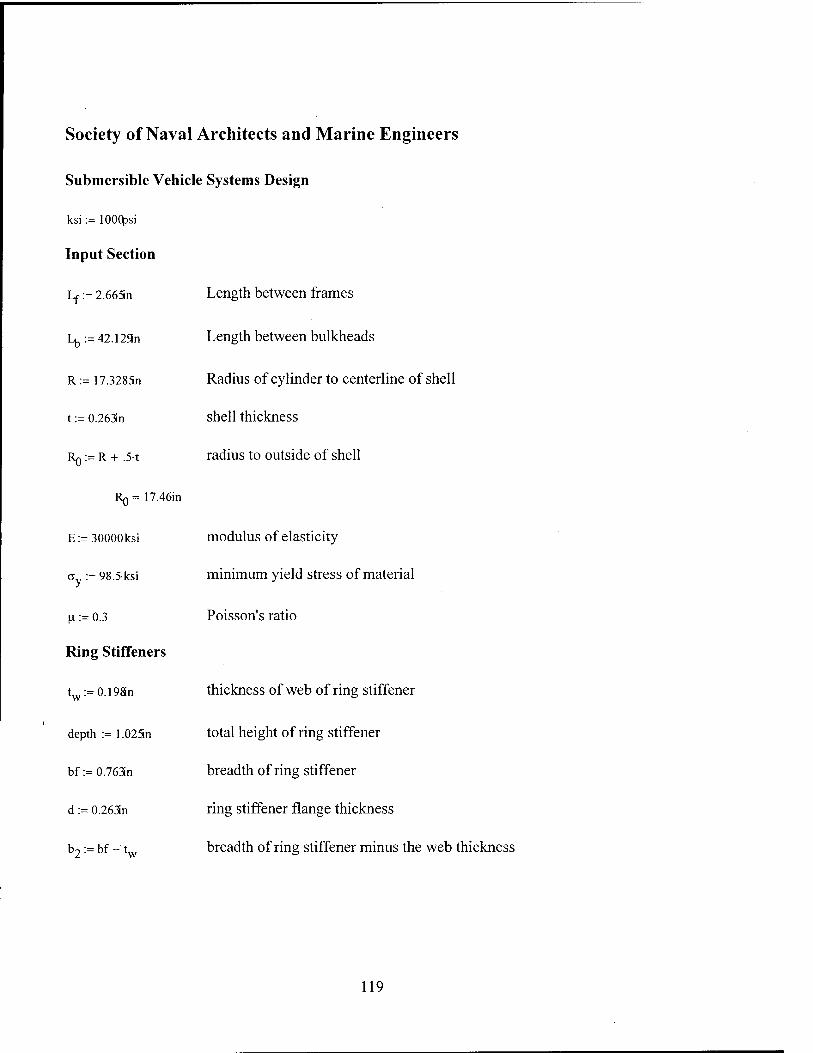
Society of Naval Architects and Marine Engineers
Submersible Vehicle Systems Design
ksi:= lOOOpsi
Input Section
Lr := 2.66Sn
Lb:=42.129n
R:=17.3285n
t := 0.263n
RQ:=R+ .5-t
RQ= 17.46in
E:=30000ksi
a := 98.5ksi
|i := 0.3
Ring Stiffeners
t -=0.19811 W
depth := 1.025n
bf:=0.763n
d := 0.263n
b2:=bf-tw
Length between frames
Length between bulkheads
Radius of cylinder to centerline of shell
shell thickness
radius to outside of shell
modulus of elasticity
minimum yield stress of material
Poisson's ratio
thickness of web of ring stiffener
total height of ring stiffener
breadth of ring stiffener
ring stiffener flange thickness
breadth of ring stiffener minus the web thickness
119

c,:=.5.
2 2 tw- depth + b2-d first centroidal height of ring stiffener
^ V depth + b2d
c, =0.351in
c2 := depth - C] second centroidal height of ring stiffener
c2 = 0.674in
h := c, - d distance from centroid of ring stiffener to nearest edge of flange
h = 0.088in
R,. := R - .5 t - c2 radius to centroid of ring stiffener
R,.= 16.523in
Ar:= (twdepth + b2d) cross-sectional area of ring stiffener
Ar = 0.352in2
V=l~ \bf'ci -b2h + twc2 J moment of inertia of ring stiffener about its centroidal axis
I,. = 0.031 in4
Combined Plate and Ring Stiffener
A -=Lft area of effective plate
Asp := A + Ar area of plate and ring stiffener
Hc := depth + t height of combined plate and ring stiffener
B, := Lf - tw plate length minus the web thickness
120

clc:=.5 VHc
2 + Brt2+b2.d-(2-Hc-d)
VHc + Bll + db2 neutral axis of combined plate and ring stiffener
from outer fiber of plate (RQ)
clc = 0.4in
R := R + .5h - clc radius to centroidal axis of combined ring stiffener and shell
Rc= 16.972in
Ie:=- e 3 %-clc -Br(c,c-t) +bf-(Hc-clc) _(bf-tw).(Hc-c]c-d)
moment of inertia of combined plate and shell
Ie = 0.187in
a. Axisymmetric yielding
V» Ar + tw-t
B = 0.129
1
9 := 10-L12-V1 - |a2JJ • — 50t
R
N:=
9 = 1.605
cosh(e)-cos(e) sinh(e) + sin(e)
N = 0.774
121

ß:= UN
50- vAr+tw-t;
ß = 1.675
f
H:=- V
sinh — cos — + cosh — -sin —
sinh(e) + sin(e)
H = -0.833
Py:= VR
1 + H f0.85-B
V 1 + ß
py = 1927.7psi
b. Lobar Buckling
Pb:= 2.42 E
(,V)
t
2R _
l]
_2R -fef. pb= 10369.943psi
c. General Instability
m:= TtR
h
n:= 1
122
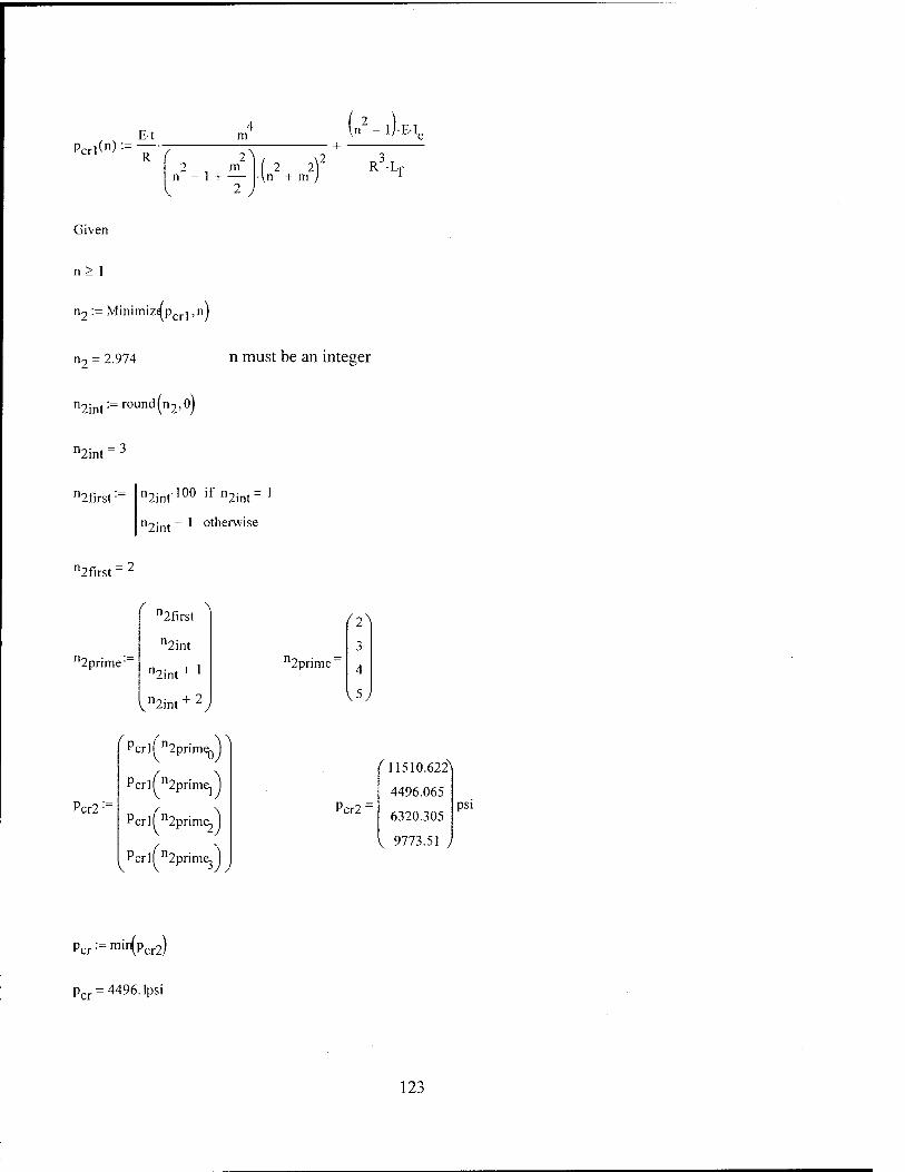
Perlen) :=—7 E-t
R
m
2 , m n - 1 + —
2 J
(n2 - l).E-T
(2 lf R Lr
Given
n> 1
n2 := Minimiza pcr j, n J
n2 = 2.974 n must be an integer
n2im:= round (n2,0)
n2int" 3
^first ■ n2int100 if n2int =
n2int ~ ' otherwise
^first:
2prime"
f n2first ^
n2int
n2int + l
Vn2int+2y
'Pcrlfn2 ■ ^
Pcr2 :=
iprime^
Pcrlf n2prime,
Pcr/^prim^
Peril n2prime.
12prime" 3
4
V5y
Pcr2:
^11510.622^
4496.065
6320.305
V 9773.51 )
psi
Per := min(Pcr2)
pcr = 4496.1psi
123

Summary
Axisymmetric Buckling
p = 1927.7psi
Lobar Buckling
pb = 10369.9psi
General Instability
pcr = 4496.Ipsi
124

MIT 13A Professional Summer Submarine Design Trends
PROGRAM TO COMPUTE SUITABILITY OF SUBMARINE DESIGN PARAMETERS.
Ref: "Hull Material Trade Off Study", D Fox, Jan 94
Define input parameters:
ksi= lOOOpsi
Global Variable Inputs:
e = o.o-in Eccentricity
Material:
GY = 98500psi
E = 3000(ksi
v =0.3
Yield Strength
Modulus of Elasticity
Poisson's Ratio
Geometry:
D = 34.657in shell diameter
R = D
2 shell radius
tf = .263in flange tickness
LfS i 2.665n frame spacing
Wf = .763in flange width
U = = 42.129 in bulkhead spacing
tw = .19Sn web thickness
tp-= = 0.263n shell thickness
K = .762in web height
125

tp R] := R - -t- Frame Radius
2
Rl = 17.197in
Af := tf wf Frame flange, web area:
A\v := twhw
A := Af + Av Frame Area = Flange + Web
A = 0.352in2
PARTI SHELL YIELDING
Von Sanden and Günther (1952)
PNA Section 8.4
B:= »w tp
A + tw tp Area ratio
0 :=Lf- 311 .')
2 T4
(R'p)2
cosh(e) -cos(e)
sinh(e) + sin(e)
Slenderness parameter
Deflection coefficient:
ß:= 2-N
A + twtp ■(.-,')
0.25
£ Frame flexability parameter:
ß = 1.676
r-.= V 2,
1 + ß Frame deflection parameter:
r = 0.269
126
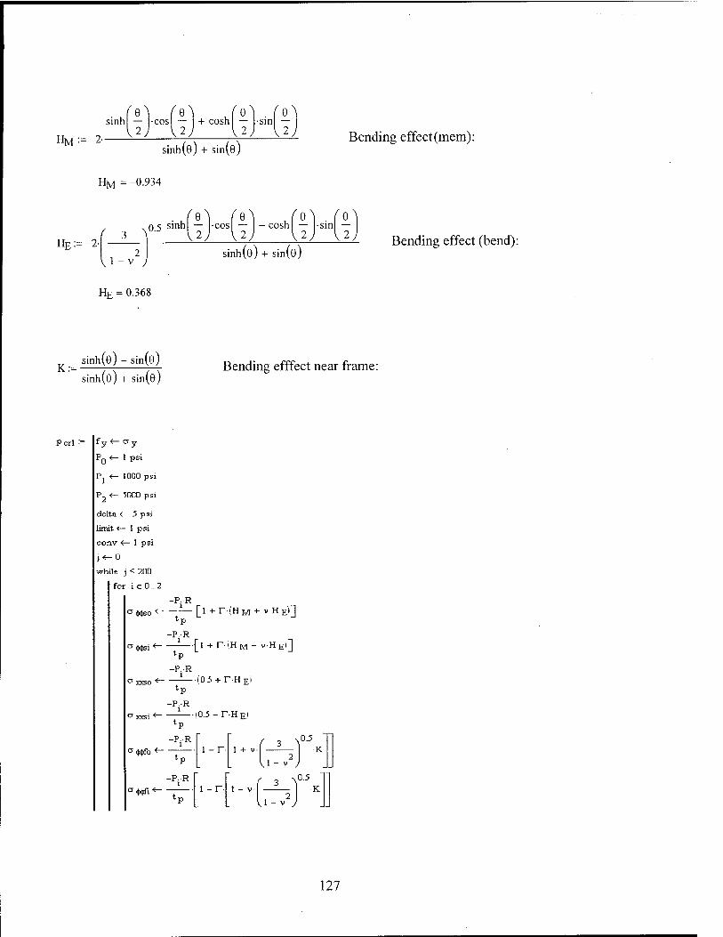
sinh
HM:=-2-
ft — |-cos| — I + cosh
\2) V2
f e\\
V ^ J sin
sinh(e) + sin(e) Bending effect (mem):
HM = -0.934
HE:=-2- \ 0.5 s'nn
f a\
V2.
/o\
\2) cosh •sin
vl -v J
HE = 0.368
sinh(e) + sin(e) Bending effect (bend):
K:= sinh(e) - sin(e)
sinh(e) + sin(e) Bending efffect near frame:
Perl fy <-Oy
PQ <- 1 psi
P. <- 1000 psi
P2 <— 5000 psi
delta <— 5 psi
limit <— 1 psi
conv <— 1 psi
j^O
while j < 200
for ie 0.2
-P.R
°<Wso *~~ [l +r-iHM + V-HE'I] tp
-P.R aWsi*~
1 _1 + r-iHM- v-HEi]
tp
-P.R a xxso *~
* 1.0.5 +r-H£i tp
-P.R
Oxxsi <— A
0.5 - r-H E.'i tp
-P.R l
" r / , \°-5 i °#fo *- i -r- J 1 tp L li-v2
a «Wifi ■«—
-P.R l l - r- 1 ■■( 3 1
0.5
■K tp . l.-.'J
127
a Qtfo ■
' Wtfi '
a 2 '
lP
-PR l
-PR l
lP
-PR l
~~<V" ° •(■too
a«Ei
° xxso
° xxsi
° it"Mb
° iMfi
o xxfo
V. ° xxfi
05- r(—-—| K
V i - '
-*2
° 3 <- O Sy3
-*7
°SYM<- (a l -ci a2 + a2 J
1
( 2 2V ^3 -0304 + 04 ) °SYF
o SY <— max °SYM
\\
°SYF
stiess. <— o sy
test. <— pfy - o sy1
testp shel <—
conv
test, dav <
break if stress. - fy < limit
PQ<-PJ if shel dav > 0
P2*-Pj if shel dav < 0
P1^V 'P2-P0'
OUt, (r- j - 1
out
128

Perl = ' 1994.1 r
Peril :=Pcrl0lpsi
pcrit=1994.1psi
PART 2 LOBAR BUCKLING
Windenberg Approx of Von Mises (1933)
Assumes n lobes = Pi*D/L
Collapse pressure:
2.42E-
PCLB:=
,2.5
D
Lf *p 0.45 — U') 0.75
PcLB=10369.9psi
PART 3 GENERAL INSTABILITY
Corrected Bryant Formula (1954) for better model test correlation
Pressure loading is:
P := 6000psi
Compute effective frame spacing
P
KXP)
\|,(,v) y = 0.717
Comput e ck :ar length:
Lc := Lf - tv
129

ti] := 0.5-^1 -y
ri] =0.266
Web thickness:
ti2 := 0.5-yi+y
n2 = 0.655
tw = 0.198in
Fl
9 1 cosh(n|-0J - cos(n2-6)
cosh(n]-0)sinh(nie) cos(n2e)sin(n2e)
n2
must be less than 1.00
Fi = 0.958
Fi is almost a linear decreasing function for pressures from 1 to 10000 psi with an average value
of 0.91. This will be used in the following analysis as the pressure is the unknown and therefore
the above equations cannot be directly used.
Fi := 0.96
Leff-Lc'Fl + tw Effective shell plate length:
Lgff = 2.566in
Theoretical critical lobe number values are:
i:=0..2
(2\
n :=
v4y
Aeff :=Lefftp
2 Aeff = 0.675in
Circumferential Lobes
Effective plate area:
130

m:= 71" Ls
Longitudinal Lobes:
m= 1.292
hw + tf
yna-
"w
v_2 •Af-
fK + ip^ •Aeff
Aeff + Aw + Af
Frame-plate neutral axis (ref web centre+ toward flange):
yna=-0.237in
Uses Parallel Axis Theorm: Icor = I + Ad2
Moments of inertia for plate,flange,web:
IP:= Lefftp"
12
twhw
12
Wf-tf
12
Ipcor :_ 'p + Aeff LV 2 ,
+ Yr
nvcor :_ nv + Aw^ynaj
!fcor := !f + Af
Total:
V 2 Yna
*eff :~ 'pcor + nvcor + 4c< Moment of Inertia corrected for neutral axis.
Ieff =0.185in4
The critical Elastic General Instability pressure is:
131

PcGI. == E-tr m w2- ■E-'eff
' R / \2 . m
h) 2 2
+ m
Min Pressure:
PcGI =
f \\ 1.15x 10
4.46 x 10³
^ 6.253 x 10³
psi
(2\
3
,4,
PcGI := mir(PcGl)
pcGI = 4460.2psi
ngi:=3
Summary
Axisymmetric Buckling
Pcrit= I994.1psi
Lobar Buckling
PcLB=10369.^si
General Instability
PcGI = 4460.2psi
ngi=3
2 R3'.Lf
132

Analytic Solution
Definitions
ksi := 6.89475710 Pa
E := 3000(ksi
R:=17.3285n
D:=2R
o := 98.5ksi
L:=2.665n
Lb:=42.129n
H:=.3
t := 0.263in
Ring Stiffeners
tw:=0.19Sn W
H:= 1.025n
b:=tw
bf:=0.763in
Modulus of Elasticity
Radius of cylinder to centerline of shell
Diameter of cylinder
Yield strength
Length between stiffener centers
Distance between bulkheads
Poison's ratio for Fe/Steel
Shell thickness
thickness of web of ring stiffener
height of ring stiffener
faying width of stiffener (from P&S for I beam stiffener)
breadth of ring stiffener
b2 := bf -1 breadth of ring stiffener minus the web thickness
d := 0.263n
Lbnash := L - bf
ring stiffener flange thickness
distance from flange edges
133

c, := .5. yH2 + b2d
2
V VH + b2d j first centroidal height of ring stiffener
c, =0.351in
C2:= H - Cj second centroidal height of ring stiffener
c2 = 0.674in
h := c, - d distance from centroid of ring stiffener to nearest edge of flange
h = 0.088in
R,. := R - .5t - c2 radius to centroid of ring stiffener
R,.= 16.523in
Ar := (twH + b2d) cross-sectional area of ring stiffener
Ar=0.352in2
v^).(b, 1 ~b2h +VC2 moment of inertia of ring stiffener about its centroidal axis
lr = 0.031 in
Aeff:=Ar (vT
effective area of stiffener eqn [24a] from P&S
Aeff = 0.369in
a := ■ V:ff Lt
ratio of effective frame area to shell area eqn [62] P&S
a = 0.526
ß := - ratio of faying width to frame spacing eqn [62] P&S
ß = 0.074
134

Combined Plate and Ring Stiffener
Ap:=L-t area of effective plate
Asp := Ap + Ar area of plate and ring stiffener
Hc:=H+t height of combined plate and ring stiffener
Hc = 0.107ft
Bl:=L-tw plate length minus the web thickness
clc:=.5| VHc
2 + Brt2+b2-d.(2.Hc-d)
twHc + Brt + db2
neutral axis of combined plate and ring stiffener
from outer fiber of plate (R0)
clc = o.4in
R„ := R - .5t - c lc radius to centroidal axis of combined ring stiffener and shell
Rc= 16.797in
'-T L.clc^Br(clc-l)3 + bf-(Hc-c,c)3^(bf-,w)-(Hc-clc-d)3
moment of inertia of combined plate and shell
Ie = 0.187in
a. Buckling of unreinforced shells
von Mises bucking pressure:
n := 1 guess at number of waves around the circumference
135

Purl(n):= E.A l 1
/ \4
+ [ (■)' 1 ■/♦I !T)1 2
RJ
[M?)1 2 n + f—1
2" 2
M.-M2).
Given
n> 1
n j := Minimizapurj ,nj
nj = 10.906 n must be an integer
n]im:= round (nj,0)
nlint=11
1 prime-
Sinf-,N
"lint
nlint+ '
<nlint+2,
^Purl^lprime^
Purl:
Purlfnl prime,
Purl^lprim^
Purlfnlprime3
pur:=min(purl)
pur = 9272.3psi
136

b. Axisymmetric Buckling
Pcab: y<-0
limit*- lpsi
test <— lpsi
conv <— lpsi
j<-0
while j < 1
1 r ii<---v' -T
n2<--Vi + y
4 F, «--
cosh(n,-9) -coslr|2-9)
9 cosh In, ]-9]sinhlr] j-9) cos(r|2-9lsinlr|2-9
n, 12
cosh (n. ]-8]sinlr|2-9J sinh (TJ |-9)cos(r|2-9)
12 11
coshfri |-9J-sinhlr| j-9) coslr|2-9Vsinlri2-9)
12 1l
coslri2'9)sinlrt2-9j cosh I n ]-8Vsinhlr| j-9]
12 11
2 cosh (n j-9J-5inhlTi j-9| coslr|2'91-sinf r|2'6)
1, 12
cosh (n |-9J-sin(r]2'ö) sinhfrj j-9]-cosln2'6)
1 12 1l
__ 2 cosh (TI |-9)sinhlri ]-9J cos(n,2'9)'s'n(l2'®)
1l 12
- P + (l - ß) F,
denoml <— A F22 .F^.d-^U^, I + F4Ml-M + ,
l-V 1-M
, 3 'l I 0.91 denom2 <- | - -A- F2 - u-F4- I
■J 1 -u
J— + denoml - denom2
2-E
break if [p 2-test| < limit
lest <- pc2
j<-j+ 1
Pc2 out <
u conv
out *- j
137

Pcab =
( A 2.141 x 10
I 2 ,
Paxiy^PcabQ-'P5'
paxiy=2140.7psi
c. Asymmetric Collapse (Lobar buckling)
Windenberg Approx of Von Mises (1933)
Assumes n lobes = Pi*D/L
2.42 E
PcLB: D
2.5
L t 0.45 — D JD (■V)'
0.75
pcLB= 10369.9psi
d. General Instability of shells and rings
X:= 7I-R
"Lb"
PcGI<n) := — f Bt
R
\n2- lj-EI
1 + — 2; l\$ R3L
n:= 1
Given
n> 1
n2 := Minimiz^pcQj,n)
n2 = 2.974 n must be an integer
138

n2int:= round (n2,0)
12int:
2prime'
n2int - ]
n2int
n2int + l
Vn2int+2y
Pcgi2 :=
^PcG/n2prim^^
PcGlTn2prime1
PcGlfn2prim^
PcGlfn2prim^
Pcgibryant := mir\Pcgi2)
Pcgibryant = 4496. lpsi
Summary
Lobar Buckling
pcLB= 10369.9psi
Axi symmetric Buckling
Paxiy=2140'7Psi
General Instability
Pcgibryant =4496. lpsi
^int:
139

This page intentionally left blank
140

Appendix C: Codes for Test Cylinder 2.a
141

AMERICAN BUREAU OF SHIPPING
Rules for Building and Classing Underwater Vehicles, Systems, and Hyperbaric Facilities
Definitions
ksi:= lOOOpsi
E:=30000xsi
v := 0.3
Modulus of Elasticity
Poisson's Ratio
öy := 65500psi Yield strength
Shell Parameters
Ls := 1.366n
Lc := 8.636n
R:=8.4179n
t := 0.0858n
■.=-*♦;
Distance between stiffeners
Distance between bulkheads
Mean radius of shell
Thickness of shell
Outer radius of shell
R0 = 8.461 in
Do^-R„
Ring Stiffeners
tw := 0.044n
depth := 0.531 Sin
bf:=0.39S!n
b2:=bf-tw
Outer Diameter of shell
thickness of web of ring stiffener
height of ring stiffener
faying width of stiffener (from P&S for I beam stiffener)
breadth of ring stiffener
breadth of ring stiffener minus the web thickness
142

d := 0.078n ring stiffener flange thickness
Lu := L -1 Unsupported spacing between stiffeners
Ljj = 1.322in
L-ma^Lg,!^)
Cl:=.5-
L= 1.366in
f 2 2^ tw-depth +b2-d
V depth + b2d first centroidal height of ring stiffener
Cj =0.143in
c2 := depth - c. second centroidal height of ring stiffener
c2 = 0.389in
h := cj - d distance from centroid of ring stiffener to nearest edge of flange
R^ := R + .5-t + c2 radius to centroid of ring stiffener
Rj = 8.85in
A :=(twdepth + b2d) cross-sectional area of ring stiffener
As = 0.051in2
L := ( - ]•( bf-cj3 - b2h3 + t c2 ) moment of inertia of ring stiffener about its centroidal axis
1,.= 1.219x 10_3in4
Rf := R + .5-t + depth Radius to tip of the stiffener
Rf=8.993in
143

Combined Plate and Ring Stiffener
Le := min 1.5-jRt N
. 0.75 Lc .
Le= ].025in
Ap:=Lt area of effective plate
Asp:=Ap + As area of plate and ring stiffener
H := depth + t height of combined plate and ring stiffener
Hc = 0.051ft
Bl=L-tw plate length minus the web thickness
'lc- twHc
2 + Brt2+b2d(2Hc-d)
twHc + B,t + db2 neutral axis of combined plate and ring stiffener
from outer fiber of plate (R0)
c]c = 0.174in
Rp := R - .5-t + c]c radius to centroidal axis of combined ring stiffener and shell
Re = 8.549in
^-3 Lclc3 " B,-(clc - t)3 + bf-(Hc - clc)3 - (bf - tw)-(Hc - c]c - d)3
moment of inertia of combined plate and shell
le = 0.008in4
General Equations
M:= Rt
M = 1.607
144

>tM n4 •M
9 = 2.066
Q>i
N:=
Q= 1.033
cosh(2Q)-cos(2-Q)
sinh(2Q) + sin(2Q)
N = 0.942
G:=2 (sinh(Q)cos(Q) + cosh(Q)sin(Q))
sinh(2Q) + sin(2Q)
G= 0.835
H:= sinh(2Q) - sin(2Q)
sinh(2Q) + sin(2Q)
H = 0.631
a Inter-Stiffener Strength (6.19.1)
1) Inter-stiffener strength equations
This equates to axisymmetric buckling
A:=A„ External stiffeners Effective area of plate and stiffener
A = 0.046in2
All-- |G
A + tw-t + 2N-t-L
e
F = 0.209
145

yield pressure at midbay and midplane of cylinder
'*R
1 -F
Py = 844.1 psi
This corresponds to Lobar buckling
von Mises buckling pressure for a cylinder
nv
>
2.42 E- URJ
3 r U2)4. L 0.45
_2-R {2-Rj _
Pm = 29< *7.7psi
maximum allowable working pressure for inter-stiffener strength
Pm Pm it < 1
2 P y
V f P ^ '- y
I 2-PmJ
6 V lf 7" > y
3
if l<-^<3 py
m — = 3.492 py
Pc = 703.4psi
Paits:=Pc-8
Paits = 562-7psi
146

2) longitudinal stress
limiting pressure corresponding to the longitudinal stress at stiffeners reaching yield
No direct correlation to major failure modes
\
y:=
A-l 1-^ 2y
A + tw-t + 2-N-t-L
e
pl:=
2-ay-t
R 1 +
( 12 ^
\\-v )
•y-H
Pj = 848.5psi
maximum allowable working pressure for longitudinal stress
Pals:=Pl-67
Pa)s = 568.47psi
b Overall Buckling Strength (6.19.5)
X:= 7T-R
n:=l
A2(n) := n - 1
AjCn) :=
A2(n) +
E-t pnl(n):=—Aj(n)+ ^
E-Ie-A2(n)
R L
147

Given
n> 2
n2:=Minimiz^pn],nj
n2 = 3.957 n must be an integer
n2im:= round (n2,0)
n2int = 4
12first • n2im100 if n2in,= l
n2int ~ ' otherwise
^first = 3
12primc
f n2f.rst A
n2int
n2int + '
^n2int+2J
Pn2:=
nlf n2primeQ
nlf^prime, J
nlf n2prime, J
nlf n2prime, J
Pn := min(Pn2)
pn = 6498.2psi
Paol:=Pn-5
Paol = 3.249x 10 psi
12prime, = 4
Pn2
( 3^ 8.609x 10
6.498 x 10³
7.797 x 10³
1.054x 10⁴
psi
148

Summary
Axisymmetric Buckling
P = 844.1psi
Lobar Buckling
Pm = 2947.7psi
General Instability
pn = 6498.2psi
n2int = 4
149

Germanischer Lloyd
1988 Edition
Chapter 2 - Submersibles
MPa:=106Pa
ksi := 10 psi
General Definitions
E:=30000xsi Modulus of Elasticity
L, := 1.36än stiffener spacing
L3 := 8.636n length of cylinder between bulkheads or lines of support
s :=0.0858n thickness of shell
R:=8.4179n radius to centerline of shell
v := 0.3 Poisson's Ratio
k:=65.5ksi minimum yield stress of material
Stiffener Dimensions
ef :=0.078n flange thickness
df:=.I775n width of flange from web to edge of flange
b2:=2df
dw := 0.4539n Height of web
ew := 0.044n web thickness
b := cw width of stiffener ring in contact with shell
150

A, = effe + 2-df) + e d cross-sectional area of stiffener ring 1 i V w 1/ w w
,. 2 Aj = 0.051in
Hstiff:=dw+ef
Hstiff=0.532in
1 ewHstiff +b2ef
2 ew-Hstiff+b2ef
cj =0.143in
c2:=Hstiff-cl
c2 = 0.389in
h2 := C] - ef
h2 = 0.065in
h-\-3 (e + 2df-)cj - (2df)h2 + ew-c2 Centroidal Moment of inertia of ring stiffener
3. 4 Ij = 1.219x 10 in
e := c2 + .5s distance from stiffener centroid to center of shell
e = 0.432in
Effective Stiffener and Shell
Letest :=b + V2R-s
Letest = 31.645mm
V= Letest lf Letest - Ll
Li otherwise
L£= 1.246in
Effective length of shell (eqn 45a,b)
151

A,-e Les 3
le := -— + Ij + —— Moment of Inertia of combined plate and shell
l + Aj ' 12
Les
Ie = 7.732x 10 3in4
Hstiffc:= Hstiff + s Total height °f stiffener and plate
Hstiffc = 0.618in
d,:=s
bs,:=Le -ew
1 evvHstiffc + b2"ef +bsj-s-(2-Hstiffc-s) Cjc :- —
2 ewHstiffc+b2ef+bsls
c,c = 0.435in
c2c:=Hstiffc_clc
c2c = 0.183in
Ro := R - .5 s + c2c radius of stiffener ring centroid including effect of Le
Rj, = 8.558in
R2 A := A j Modified area of stiffener ring
«o2
A = 0.049in2
ei:=c2c+.5-s
ej = 0.225in
152

2.4 Asymmetrie Buckling (Lobar but not named this)
v=- 7I-R
n:=2 initial guess
ßnl(")-=
( 2 n
+ 1
^i ;
V2 2f 2 n2 s -I n - 1 + A.j
12 R2.(,-v2)
2 i «i 2 n - 1 + .5-A.j
Pn](n):=- Esßnl(n)
R
Given
n>2
n := Minimiza pn| ,n)
n = 13.832 n must be an integer
ngint:=round(ng'°)
ngint = 14
1gfirst • ngint-100 if ngint=l
neint - * otherwise
gfirst = 13
gpnme •
"gfirst
"gint
ngint + ]
^"gint + 2
n gpnme"
^13\
14
15
153

Pn2:
Pnl(ngprimeoy
Pnl^gprime,)
Pnl^gprime^)
Pnl[ngprimej)
pcr:=min(pn2)
pcr = 2814.7psi
3.3.3 General Instability
L:=L3 Spacing between effective stiffeners
x2-, 7I-R
\2 = 3.062
ßn2(n):=-
P0(n)
Pl(n):=
{n2 - 1 + 0.5^22)-(n2 + X2
2)
E-s-ßn2(n)
R
(n2-,). EL
Ro'-L]
Pnla(n):=P0(n) + Pl(n)
n:=2
Given
n>2
154

n2 := Minimiz^pn]a,nj
n7 = 4.01 n must be an integer
nT,„t := roun ^int • d(n2,0)
12int:
12prime'
^2int-lA
n2int
n2int + !
vn2int+2y
Pnlaf n2prim&.
Pg2:=
Pnlaf n2prime]
Pnlafn2prim^
Pnlaf n2prime,
pg:=min(pg2)
p =6184.9psi
PR2:
8.442x 10
6.185x 10
7.296x 10
V9.812x 10 )
psi
2.6 Symmetric Buckling (axisymmetric)
More Definitions
Default values for Elastic-Plastic Region (Eqns are below)
E ■= E Secant Modulus = Young's Modulus for elastic region
Ej:=E Tangent Modulus = Young's Modulus for elastic region
v := v Poisson's Ratio, elastic-plastic; = Poisson's ratio in elastic
155

a := 177}
2i>2 s R
shape factor
a = 0.06-
C5:=o-Lj calculation factor for symmetric buckling
C5 = 2.066
Past := 2s E
R2.ff^7) critical pressure, elastic, calculation factor
Past = 3772.56^Dsi
Must guess pressure and then change when compared to pm at bottom of calculation
G:= Past
1 C6:=--JT=G
1 C7:=— J] + G
' 2
C8:-C5C6
C9:— C^Cy
cosh(Cg) -cos(c9)
C5 cosh(c8)sinh(c8) cos(c9)sin(c9)
FT:=
cosh(Cg)sin(c9) sinh(Cg)cos(c9)
C7 + C6
cosh (Cg)sinh(Cg) cos(c9)sin(c9)
156

cos(CgJsin(CpJ cosh (CgVsinhl Cgi
F3:=
Q
1 -v cosh(CgVsinh(Cg] cosfCpl-sinlQO
Q C, -6 W
coshfCglsinfC^J sinmCgVcoslQj
C7 C6
2 cosh(CgVsinh(Cgj cosfCpjsinlCpj 1 -v
CA C,
C
( ,,\
\ ^J s-L
10- A b + — +
s-Lj Lj ( b^ 1
I LlJ
'IT 0.91
1 -v
ao:=- -p-R
Gx:=oo|- + C10Cll^
ax=-4.675 x 10 Pa
G<j>:=Gc>-( l-C10-F2 + v.C10-CirF4
ax = -5.789X 10 Pa
Gxl:=Go| 2~C10"C11'F4
oxl = -2.292x 10 Pa
G<j)i:=Go-(1-cio-F2-v-cio-cirF4)
CT., = -5.074X 10 Pa
157

°4> CTx
.8k = 52.4ksi
If the calculated stress is greater than .8k then must find E,, Es, etc.
_ _
(Tj = 77.165ksi
CJ:=-K0GX
s, := —
E] =2.799x 10
a:=k[ .8+ .2-tanh[ 5— e,-4
a = 65290.1psi
E := }.8+ 0.2atanh 5-
E = 2.799x 10
V k
3
E 0.8 + 0.2J tanhl 5— • E -4
Es = 23254. lksi
Ej-E (i--*(ȣ. E-4
Ef = 480.6ksi
V= i-l-v 2 12 ) E
vp = 0.345
158

E<- ^
2-s -E„
R2j3-( 1 - vp2
Paa:=
Kl:=^l-K0 + K0
Et
H4:=
H3:=
4-ll-Vp J.K,
H2:=
= [(l-2.vp)-(2-vp).K0]
H 1 •=
C:=
1 + H4 H2 -3.^1-vp
1 + H2'H3'H4^
v„H p'"i ;
Co = -0.764
/
C2:=
C2 =
\
1 H3 H4
H, V 1 J
0.167
Cj:=
/ 2 ^ H2 H4
1 H,
C,=
v i y
0.555
C0:= cr<VVc32
1 -v.
C0 = 0.163
159

a, :=
trial :=
4(—|
3- °2 ( c \
p C,
2
> s' » 2
■R
arLj
trial = 0.353
Iterate on m until trial <= trial2
m:= 1
m tria!2:= f — (m + 1)
tria!2 = 1
Pm:=PaaC0'
cxi-L
V 7t-m
I'M | 1 + -
4
( Tt-m ^
°rLiy
pm= 1029.8psi
p - 103Q5S1 iterate on pressure until pnl is equal to p
Summary
Axisymmetric Buckling
pm= 1029.8psi
Lobar Buckling
pcr = 2814.7psi
General Instability
pg = 6184.9psi
160

Society of Naval Architects and Marine Engineers
Submersible Vehicle Systems Design
ksi := lOOOpsi
Input Section
Lf:=1.366n
1^ := 8.636n
R:=8.4179n
t:=0.0858n
RQ:=R+ .5-t
RQ = 8.461in
E:=30000ksi
a := 65.5-ksi
|i := 0.3
Ring Stiffeners
tw := 0.044m W
depth :=0.5319n
bf:=0.39Sin
d := 0.07Sn
b2:=bf-tw
Length between frames
Length between bulkheads
Radius of cylinder to centerline of shell
shell thickness
radius to outside of shell
modulus of elasticity
minimum yield stress of material
Poisson's ratio
thickness of web of ring stiffener
total height of ring stiffener
breadth of ring stiffener
ring stiffener flange thickness
breadth of ring stiffener minus the web thickness
161

Cl:=.5-
( 2 l\ tw- depth + b2-d
twdepth + bjd
cj =0.143in
first centroidal height of ring stiffener
c2 := depth - cj second centroidal height of ring stiffener
c2 = 0.389in
h := c j - d distance from centroid of ring stiffener to nearest edge of flange
h = 0.065in
Rj := R + .5-t + c2 radius to centroid of ring stiffener
R,. = 8.85in
Ar := (twdepth + bjd) cross-sectional area of ring stiffener
Ar=0.051in2
lr := - H bf-cj - b2-h + twc2 J moment of inertia of ring stiffener about its centroidal axis
1,.= 1.219x 10_3in4
Combined Plate and Ring Stiffener
A •= Lj-1 area of effective plate
Asp := A + Ar area of plate and ring stiffener
Hc := depth + t height of combined plate and ring stiffener
Bj := Lf - tw plate length minus the web thickness
162

clc:=.5| tw.Hc
2 + Brt2+b2.d.(2.Hc-d)
twHc + Bjt + db2
neutral axis of combined plate and ring stiffener
from outer fiber of plate (RQ)
c]c = 0.174in
R := R - .5t + c, radius to centroidal axis of combined ring stiffener and shell
R^ = 8.549in
Lf clc3 - Br(clc - t)3 + bfK - clc)3 - (bf - SvMH, - clc - d)3
moment of inertia of combined plate and shell
ie = 0.008in
Axisymmetric yielding
B:= V1
Ar + tw-t
B = 0.069
9 := 10- Mivir V2-Ry
50t
R
9 = 2.066
N: cosh(e)-cos(e) sinh(e) + sin(e)
N = 0.942
163

ß:= UN
T Ar + t.„-t 50._ V r w J R
ß = 1.947
H:=
3sinh — cos — \2) {2
+ cosh fa\
\*J sin —
\2
sinh(e) + sin(e)
H =-0.681
VR
y ro.ss-i^ 1 + H
V 1 + ß
p =814.733psi
Lobar Buckling
Pb:= 2.42 E
U')
t
2R
r
_2R -fe)1 pb = 2.948x 10 psi
General Instability
7I-R m:=
h
n:= 1
164

Et Perl*") := Y (
(n2-lW
2 , m n - 1 + —
(2 2f R Lf
Given
n> 1
n2 := Minimize pcr|, nj
n2 = 3.957 n must be an integer
n2int:=round(n2'°)
n2int = 4
^first • n2int-100 if n2im=l
n2int - * otherwise
12prime'
n2first
n2int
n2int + ]
Vn2int+2y
Pcr2 :=
^Pcrlf^prime^
Peril n2prime.
Peril n2prime,
Pcrlf n2prime,
in(Pcr2)
p = 6498.2psi
165

Summary
Axisymmetric Buckling
p = 814.7psi
Lobar Buckling
pb = 2947.7psi
General Instability
pcr = 6498.2psi
166

MIT 13A Professional Summer Submarine Design Trends
PROGRAM TO COMPUTE SUITABILITY OF SUBMARINE DESIGN PARAMETERS.
Ref: "Hull Material Trade Off Study", D Fox, Jan 94
Define input parameters:
ksi= 100Q)si
Global Variable Inputs:
e = 0.0-in Eccentricity
Material:
öy = 65500psi
E = 3000(ksi
v =0.3
Geometry:
R=8.4179n
D = 2R
Lf = 1.36än
Ls = 8.636in
tp = 0.0858n
tf = 0.078n
wf = 0.399fn
tw = 0.044n
hw = 0.4539n
Yield strength
Modulus of Elasticity
Poisson's Ratio
shell radius
shell diameter
frame spacing
bulkhead spacing
shell thickness
flange tickness
flange width
web thickness
web height
167

Compute areas:
Rf:=R+-ü 2
Frame Radius
Rf = 8.461 in
Frame flange, web area:
Af :=tf Wf
A\v := t\v'nw
A := Af + Av Frame Area = Flange + Web
A = 0.051 in2
PART 1 SHELL YIELDING
B:= tw'tp
A + tw-tp
Area ratio
B = 0.069
:=Lf- ;-(,-v>)
Slenderness parameter:
6 = 2.066
N cosh(e)-cos(e) sinh(e) + sin(e)
Deflection coefficient:
N
2-N
A + tw-tp
-,0.25
•U2) J**r Frame flexibility parameter:
ß = 1.947
168

T:=
l -- V 2y
-B
1 + ß Frame deflection parameter:
r = 0.265
HM:=-2"
sinh — -cos — + cosh QS
\ ■ fe sin
sinh(e) + sin(e) Bending effect (mem):
HM = -0.835
f - x0.5 sinh HE:=-2-
\\-v" )
HE = 0.557
sinh(e) - sin(e)
sinh(e) + sin(e)
'e^ \^J
cos| — I - cosh sin ,2y
sinh(e) + sin(e) Bending effect (bend):
Bending efffect near frame:
169

P crl := fy <- Oy
P0 «- 1 psi
Pj <- 1000 psi
P2 «- 2000 psi
delta <- 5 psi
limit<— 1 psi
conv <— 1 psi
while j < 20
for i-s 0. 2
rl«60 '
-PR
rtosi<
~- -[l+r-iHM +v-HEt] lp
PiR
r— [i + riHM-vHEi]
-PtR < —i0.5 + r-HE'
-PR •i0.5-r-HEt
rtofo '
1 «fr
°3Ddb*-
-P.R l
-P.R l
-P.R l
axxfi<- -P.R
l
i -r
l -r
0.3 - r
0.5 + r
1 + V
0.5 ■K
05
( 3 >|
\l~ v J
( 3
0.5
0.5 K
1-v
^WBO^
rWBi
0Sy<~
°xxfo
a 1 <- ° sy
CT2<-0Sy,
a 3 <~ cr sy,
o
2
O 4 *- O Sy
170

ÜSYM<- ( 2 A [a i -a [-a 2+ 02 )
(■ 2 2
/ a SY <— max
CSYM \\
V ^SYF )J
stress. <— a SY
test.«- ify-csYi
test. shel<-
dav <-
conv
test.
conv
break if IstresSj - fy < limit
P0<-P. if sheldav>0
P2^P, if sheldav<0
pi^V
j<-j+ 1
iP2-P0'
out. <— j - 1
out
Perl 819.181
14
Peril :=Pcrl0'lpsi
Peril = 819.2psi
171

PART 2 LOBAR BUCKLING
Windenberg Approx of Von Mises (1933)
Assumes n lobes = Pi*D/L
Collapse
pressure:
2.42E-
PcLB-
fx ^5
tr Lf I'D 0.45 —
VD ^D; ■(,-v2)
0.75
PcLB = 2947.7psi
PART 3 GENERAL INSTABILITY
Corrected Bryant Formula (1954) for better model test correlation
Pressure loading is:
P:=p-gDtSF. g"
P= 1786.13 lpsi
Compute effective frame spacing
P Y:=IE" Vv)
y = 0.473
Compute clear length:
Lc==Lf- -tw
n] :=0.5>/l -7
n] =0.363
172

n2: = o.sVT + 7
n2 = 0.607
Fi:= cosh(n j •)' - cos(n2- *?
cosh(ni •0Jsinh(n ,e) cos (112 •8jsin(n2
n2
°)
F) = 0.894 must be less than 1.00
F] is almost a linear decreasing function for pressures from 1 to 2000 psi with an average value
of 0.90. This will be used in the following analysis as the pressure is the unknown and therefore
the above equations cannot be directly used.
F] :=0.90
Leff :=LcFl + lv Effective shell plate length:
l^ff = 1.234in
Theoretical critical lobe number values are: i := o.. 2
Aeff := Leff lp Effective plate area
Aeff =0.106in :
Circumferential Lobes
f2^
n := 3
v4y
Longitudinal Lobes:
m:=7i- R_
m= 3.062
173

hw + tf
yna: V 2
Af h\v + tp
■Aeff
Acff + Aw + Af
Frame-plate neutral axis (ref web centre+ toward flange):
yna = -0.129in
Uses Parallel Axis Theorm: Icor = I + Ad2
Moments of inertia for plate,flange,web:
b Leff'p
12
lw twhw
12
In-
t 3 Wf tf
12
!pcor := !p + Aeff tp + hw ^
+ yr
'wcor:= h\ + Aw(ynaj
'fcor := If + Af ftf+hv
V 2
'eff:= Ipcor + I\vcor + 'fcor
Ieff=7.711x 10 3in4
yna
Moment of Inertia corrected for neutral axis.
Determine Rf as radius to centroid of combined plate and stiffener:
The critical Elastic General Instability pressure is:
PcGI. = Etr w2- EIeff
i R ( \2 , m
(";) 2 2
+ m 3
R Lf
174

Min Pressure:
i <0 2.039x 10
PcGI = 8.546x 10³
v6.379x 103,
psi
(2 \
n := 3
14, 1
PcGI := min(PcGI)
PcGI = 6378 9psi
Summary
Axisymmetric Buckling
Pcrit = 819.2psi
Lobar Buckling
PcLB = 2947.7psi
General Instability
PcGI = 6378.9psi
175

Analytic Solution
Defintions
ksi:= 6.894757106Pa
E := 3000(ksi Modulus of Elasticity
R:=8.4179n Radius of cylinder to centerline of shell
D := 2R Diameter of cylinder
o :=65.5ksi Yield strength
L:= 1.366m Length of supported cylinder
Lf, := 8.636n Distance between bulkheads
p:=.3 Poison's ratio for Fe/Steel
t := 0.0858n Shell thickness
Ring Stiffeners
tw := 0.044n thickness of web of ring stiffener
H:=0.5319n height of ring stiffener
b:=tw faying width of stiffener (from P&S for I beam stiffener)
bf:=0.39Sin breadth of ring stiffener
b2:=bf-,w breadth of ring stiffener minus the web thickness
d := 0.078in ring stiffener flange thickness
^nash := L - bf distance from flange edges
176

c,:=.5- yH2 + b2-d2
twH+b2d first centroidal height of ring stiffener
cj =0.143in
c2:=H-Cj second centroidal height of ring stiffener
c2 = 0.389in
h := c, - d distance from centroid of ring stiffener to nearest edge of flange
h = 0.065in
Rj. := R + .5t + c2 radius to centroid of ring stiffener
Rr=8.85i
Ar := (tw-H + b2-d) cross-sectional area of ring stiffener
Ar=0.051in2
VH^Kbf-cl3-b2-h3 + Vc23 moment of inertia of ring stiffener about its centroidal axis
lr= 1.219x 10 3in4
Aeff:=Ar- effective area of stiffener eqn [24a] from P&S
Aeff = 0.049in
veff a := ■
Lt ratio of effective frame area to shell area eqn [62] P&S
a =0.415
"■I ratio of faying width to frame spacing eqn [62] P&S
ß = 0.032
177

Combined Plate and Ring Stiffener
Ap:=Lt area of effective plate
Asp:=Ap + Ar
Hc := H + t
area of plate and ring stiffener
height of combined plate and ring stiffener
Hc = 0.05lft
Bl:=L-tw plate length minus the web thickness
c]c:=.5l tw-Hc
2 + B,t2 + b2d(2Hc-d)
twHc + Bj-t + db2 neutral axis of combined plate and ring stiffener
from outer fiber of plate (R0)
c]c = 0.174in
Rc := R - .5t + clc radius to centroidal axis of combined ring stiffener and shell
Rc = 8.549in
e 3 Lclc -B,-(cIc-t) +bf.(Hc-cIc)3-(bf-tw).(Hc-clc-d)3
moment of inertia of combined plate and shell
le = 0.0iin4
a. Buckling of unreinforced shells
n:= 1 guess at number of waves around the circumference
Puri(n) E-t
R
n + .5- 7T-R
(n-R) 4
U + r ->2
/ \2 2 (n-R) n +
V L
(-2
.2-(,-p2).
2 n +
7I-R
L
178

Given
n> 1
rij :=Minimizapur],nJ
nj = 13.812 n must be an integer
nHnt:= round (nj,0)
nlint=14
'l prime"
'"lint-1^
"lint
nlint+ l
vnlint+2y
Purl( nl prime.
Purl
Purl "I I prime.
Purl "I 1 prime.
Purl "I 1 prime.
Pur := min(Purl)
p =2.816x 10 psi
179

b. Axisymmetric Buckling
Pcab: y *- 0
irnit«- lOpsi
test <- Opsi
conv +- lpsi
j«-o
while j < 20
ni *- -VT^T
i2<--Vi_n;
L e^HV)-
r , 4 coshjq|-6) - cos(n29)
8 coshlrij ■e)-sinh(ii|-9) cos(n2'6)'s,n(,l2'G)
ii n2
cosh(ri|'e)sin(n20) sinhfn, i-öVcos^-O)
]|2_ nj
coshfii |-oVsinh(T| j-o) cos(n2e)'sin(n2e)
cos(tl2e)'sin(Tl2'0) cosh(p |-6Vsinh(li je)
~~ ~ 12 1l
t 2 cosh(n,|'0)'sinh(r|i'0) cos(n2°)sin(n2°)
1l 12
cosh(n |'ö)sin(ri2B) sinh(n i-9Vcos(r]2e)
~1 i2 nj
!_ 2 cosh(n|6)sinh(n|'6) cos(r|2e)sin(Tl2-9)
ii n2
■f." a + ß + (l-ß)-F,
dcnoml 4- A F22+F2-F4-(l-2-M)
U'V + F4
2il-M + M2J 0.91
1-M
denom2 *- | — |-A-
Pc2"
F2 - M'F4
1-M
°>U
+ denornl - dcnom2
break if |pc2 - test I < limit
2-E
test <- pc2
j<-j+ 1
Pc2 out <
u conv
out <- j
180

'875.9^ Pcab = 0 V 2 J
Paxiy^PcabQ^P5'
paxiy=875.9psi
c. Asymmetric Collapse (Lobar buckling)
Windenberg Approx of Von Mises (1933)
Assumes n lobes = Pi*D/L
Collapse pressure:
2.42 E-
PcLB:= D
2.5
-o.4sji)(,vr D
pcLB= 2.948x 10 psi
d. General Instability of shells and rings
X:=- 7I-R
4
n:= 1
PcGl<n):- „ , Et
R
(n2-l)-E,
A 2 , \
n - 1 + — V 2y
(n2 + .2)
2 R3-L
Given
n> 1
181

n2 := Minimiz^pcQj,nj
n2 = 3.957 n must be an integer
n2int:= round (n2,0)
n2int = 4
^prime"1
]2int
n2int
n2int + »
rn;„, + 2 V"2int
PcGlfn2prim^
PcGlfn2prime]
csi2 * / \ PcG/n2prime2J
PcGlfn2prime5]
Pcgibryant := mir(Pcgi2)
3 Pcgibryant = 6498x 10 Psi
Summary
Lobar Buckling
PcLB = 29477Psi
Axisymmetric Buckling
Paxiy=875-9Psi
General Instability
Pcgibryant = 6498.2psi
n2int = 4
182

Appendix D: Codes for Test Cylinder 2.c
183

AMERICAN BUREAU OF SHIPPING
Rules for Building and Classing Underwater Vehicles, Systems, and Hyperbaric Facilities
Definitions
ksi:= lOOCpsi
E := 3000(ksi Modulus of Elasticity
v:=0.3 Poisson's Ratio
a := 15700(bsi Yield strength
Shell Parameters
Ls := 3.25<Sn Distance between stiffeners
Lc:=115.533n Distance between bulkheads
R:= 18.882n Mean radius of shell
t:=0.331n Thickness of shell
R0 := R + - o 2 Outer radius of shell
R0 = 19.051 in
Do:=2Ro Outer Diameter of shell
Ring Stiffeners
tw:=0.121n thickness of web of ring stiffener
depth :=2.315n height of ring stiffener
b:=tw faying width of stiffener (from P&S for I beam stiffener)
bf:=1.552n breadth of ring stiffener
b2:=bf-tw breadth of ring stiffener minus the web thickness
184

d := 0.305n ring stiffener flange thickness
L. := L -1 Unsupported spacing between stiffeners
L,, = 3.129in
L-ma^Lg,!^)
c,:=.5.
L=3.256in
tw-depth +b2d
tw-depth + b2d
cl = 0.558in
first centroidal height of ring stiffener
c2 := depth - cj second centroidal height of ring stiffener
c2 = 1.757in
h := cj - d distance from centroid of ring stiffener to nearest edge of flange
Rg := R - .5-t - c2 radius to centroid of ring stiffener
Rg = 16.957in
As := (twdepth + b2-d) cross-sectional area of ring stiffener
As = 0.729in2
1^= - fbf-cj -b2h + tw-c2 ) moment of inertia of ring stiffener about its centroidal axis
Ir=0.312in4
Rf := R - .5-t - depth Radius to tip of the stiffener
Rf = 16.398in
185

Combined Plate and Ring Stiffener
1.5-VR-t L„ := min
{ 0.75^ J
Le = 2.442in
Ap:=Lt
Asp := Ap + As
Hc := depth + t
Hc = 0.221ft
B, :=L- Kv
effective plate length
area of effective plate
area of plate and ring stiffener
height of combined plate and ring stiffener
plate length minus the web thickness
lc tvvHc
2+B,t2 + b2d(2Hc-d)
twHc+ B,t+ db2 neutral axis of combined plate and ring stiffener
from outer fiber of plate (R0)
c]c = 0.937in
R^. := R + .51 - clc radius to centroidal axis of combined ring stiffener and shell
Rc= 18.114in
L:= — Lclc3 - B,-(c,c - t)3 + bf-(Hc - clc)3 - (bf - tw).(Hc - clc - d)3]
moment of inertia of combined plate and shell
Ie= 1.946in4
General Equations
M:=
M = 1.291
186

9:= •U2)- ■M
9 = 1.659
N:=
Q = 0.83
cosh(2Q)-cos(2Q)
sinh(2-Q) + sin(2Q)
N = 0.797
G:=2- (sinh(Q)cos(Q) + cosh(Q)sin(Q))
sinh(2-Q) + sin(2Q)
G = 0.926
H:= sinh(2Q) - sin(2-Q)
sinh(2Q) + sin(2Q)
H = 0.435
Inter-Stiffener Strength (6.19.1)
1) Inter-stiffener strength equations
yield pressure at midbay and midplane of cylinder
This equates to axisymmetric buckling
A:=AC _R_ Effective area of plate and stiffener (Internal stiffeners)
A = 0.811in2
187

F:=
1 IG ^ 2,
A + tw-t + 2N-t-L
F = 0.335
y i-F
Py = 421 l.lpsi
von Mises buckling pressure for a cylinder
This corresponds to Lobar buckling
2.42 E 2R
3 r
(.- V)4. L
2R -0.4S| - =r
Pm= 13410.8psi
Pc:=
P P m .„ m if < ,
py ,__3L| if ,<^<3
V 2-P, m,
5 „ ., *m — Pv if — > 3 6 y P
Pc = 3509.3psi
188

maximum allowable working pressure for inter-stiffener strength
Paits:=Pc-8
Pait =2807.4psi
2) longitudinal stress
limiting pressure corresponding to the longitudinal stress at stiffeners reaching yield
No direct correlation to major failure modes
y:=-
A + tw-t + 2-N-t-L
e
2-cyt
R 1 +
f 12 ^2
■Y-H
vl -v J
P] = 3566.1psi
maximum allowable working pressure for longitudinal stress
Pals:=PP67
Pals = 2389.29psi
b Overall Buckling Strength (6.19.5)
K:=- 7I-R
n:=l
A2(n) := n - 1
189

A,(n):=
A2(n) + — z 2
(„M2
, , Et E-Ie-A2(n)
Pnl(n):=Y'Al(n) + 3 R L
Given
n>2
n2:=Minimizapn] ,n)
n2 = 2 n must be an integer
n2int:= round (n2,0)
n2int - 2
n2first:= n2inf100 if n2int=1
n2int ~ ' otherwise
' n2flrst '
n2int n2prime =
n2int + X
,n2int+2,
'Pnl(^n2Primeö)>
Pnlfn2prime,)
Pn2:=
Pnlfn2primeJ
^Pnl(n2prime3^
Pn := min(Pn2)
Pr = 8642. lps
12first = 1
Pn2
1.768x 10
8.642x 10
2.136x 10 psi
3.995 x 10
190

Summary
Axisymmetric Buckling
P =4211.1psi
Lobar Buckling
Pm= 13410.8psi
General Instability
pn = 8642. lpsi
n2int = 2
191

Germanischer Lloyd
1988 Edition
Chapter 2 - Submersibles
MPa:= 106Pa
3 ksi := 10 psi
General Definitions
E:=3000(ksi Modulus of Elasticity
Lj :=3.25än stiffener spacing
L3:=115.532n length of cylinder between bulkheads or lines of support
s := 0.337in thickness of shell
R:= 18.882n radius to centerline of shell
v := 0.3 Poisson's Ratio
k:= 157-ksi minimum yield stress of material
Stiffener Dimensions
ef:=0.305n flange thickness
df:=0.7125n width of flange from web to edge of flange
b2:=2-df
dw := 2.01in Height of web
ew:=0.121n web thickness
b:=ew width of stiffener ring in contact with shell
192
Ai := ef(e „ + 2df) + e -d,„ cross-sectional area of stiffener ring 1 I V W 1/ W W ^
Aj =0.729in
Hstiff:=dw+ef
Hstiff=2.315in
1 VHstiff +b2ef ci :=-•
2 ewHstiff+b2ef
Cj =0.558in
c2:=Hstiff-cl
C9 = 1.757in
h2:=c1-ef
h2 = 0.253in
h-= (ew+2df)c1 - (2df)h2 + ew-c2 Centroidal Moment of inertia of ring stiffener
. 4 Ij =0.312in
e := c2 + .5s distance from stiffener centroid to center of shell
e= 1.925in
Effective Stiffener and Shell
Letest:=b + >f2^
Letest=93-838mm
Le:= Letest if Letest < Lj Effective length of shell
Li otherwise
Le = 3.256in
193

Aj-e Les 3
Ie := — + I, + —— Moment of Inertia of combined plate and shell
] + A, ' 12
Le-s
Ie= 1.946in4
Hstiffc:= Hstiff + s Total height of stiffener and plate
Hstiffc = 2652in
dj := s
bs,:=Le-ew
1 ewHstiffc +b2ef +bsls(2Hstiffc-s) c]c:= —
2 ewHstiffc+b2ef+bsrs
Cjc = 1.715in
c2c:=Hstiffc~clc
c2c = 0.937in
1^ := R + .5s - c2c radius of stiffener ring centroid including effect of L£
R0= 18.114in
R2 A := A, Modified area of stiffener ring
A = 0.792in2
e,:=c2c+.5-s
e] = 1.105in
194

2.4 Asymmetrie Buckling (Lobar but not named this)
V=- 7I-R
n:=2 initial guess
ß„l(n):=
( 2 ^ n — + 1
2
■2 if 2 s • n - 1 + A.1
12- R2-(l-v2)
2 , <, 2 n - 1 + .5-A.j
Pnl(n):=' Esßnl(n)
R
Given
n>2
ng :=Minimiz^pnl,nj
n =10.171 n must be an integer
ngint := round (n o)
ngint = 10
^gfirst' ngint-100 if ngint =1
neint ~~ * otherwise
n gpnme ■
"gfirst
ngint
ngint + l
Vngint + 2;
n gpnme'
r9\ 10
li
V12y
195

Pn2:=
pnlf ngprime0
'cr ■
Pnl^gprime,)
Pnl^gprimej)
Pnl(ngprimej)
in(Pn2)
pcr= 12139.3psi
3.3.3 General Instability
L:=L3 Spacing between effective stiffeners
x2-, TtR
ßn2(")
n -1 + 0.SX2 )\n +l2 2 2 2
P0(") :=
P](n):=
Esßn2(n)
(n2-,). EL
RoLl
Pnla(n):=P0(n) + Pl(n)
n:=2
Given
n>2
n2:=Minimiz^pn]a,n)
n2 = 2 n must be an integer
196

n2int:= round (n2,0)
^int:
2prime"
'2int ~
n2int
n2int + ]
Vn2int+2;
Pnlaf n2prime^
Pg2:=
Pnlaf n2primej
Pnlafn2prim^
Pnlaf n2prime,
in(Pg2)
p = 9702.4psi
Pg2:
1.768x 10
9.702x 10
2.418x 10
4.525x 10
psi
2.6 Symmetric Buckling (axisymmetric)
More Definitions
For Elastic-Plastic Region (Eqns are in the program)
E := E Secant Modulus = Young's Modulus for elastic region
E(:=E
v '= v
Tangent Modulus = Young's Modulus for elastic region
Poisson's Ratio, elastic-plastic; = Poisson's ratio in elastic
a := J^T) ,v
shape factor
a = 0.02-
197

C5 := a-L, calculation factor for symmetric buckling
C5 = 1.659
2-s *E >ast := ,. critical pressure, elastic, calculation factor
past = 11567.346?si
G:=^- Past
C6:=^yfT^G
C7:=— JTTG 1 2
C8:-C5C6
C9:-C5C7
Fl:= cosh (Cg) - cos (Cg)
C5 cosh(Cg)sinh(Cg) cos(c9)sin(c9)
% + Öj
cosh (c8)-sin(c9) sinh(c8)cos(c9)
F ^ + C6 2 cosh(Cg)-sinh(Cg) cos(c9)sin(c9)
% + Gj
cos(c9)-sin(c9) cosh(Cg)sinh(c8)
F = P^ °7 " c6 3 J , _ v
2 cosh(Cg)-sinh(Cg) cos(c9)-sin(c9)
C6 + C7
198

coshfCgVsinfQO sinhlCgJcosfCg)
F4:= C
2 coshfCgVsinmCgj coslQjVsinfQj)
Cn
v \ A
2 / s-Li
'10 = A b
+ — + sLj Lj
( *>}
C„:= 0.91
1 -v
-p-R
Gx:=öo| - + ciocirF4
V=Go{ 1-C10'F2 + vC10CHF4
0xl:=tV| 2~C10'C11"F4
ax=-1.168x 10 Pa
°$i := Go{1"cioF2-vC10CHF4)
d(j) = -1.259x 10 Pa
K0:= a*
2 2 CTi:=-JCTx + a<fr ~axa$
a= 176.383ksi
a:=-K0ax
a = 182.6ksi
199

Ei :=
Ej =6.087x 10
o:=k- .8+ .2-tanh 5--EJ -4 ]
G = 155380. lpsi
.:=— 0.8+ 0.2-atanh 5- El l k
e = 6.087x 10
E
( 0.8 + 0.2- tanh
V 1>H1 Es = 1.743x 10nPa
Ej := E 1 - tanh ( E 5—E-4
10. Ej= 1.067x 10 Pa
V= 2 U JE
vp = 0.332
^
2s2-Er
^ 1 -v.
Kl:=('-Ko + Ko2)
200

Et 1 - —
HA
4-ll-vp )-K}
^[(^pH^pK] H2-=[(2-P)-(
l-2^}Ko]
H,:=[l + H4 H2 -3-^1-Vp
( H2H3H4^ 1 +
VHi ;
C3 = -0.83
C2:= 1
C]:=
H3 H4
Hl J
C2 = 0.321
H2 H4
H,
Cj = 0.458
Cn
2 „ 2 Ci^-^-Cs
1 -v.
C0 = 0.283
3- Co ( Q,\
C i;
s2.R2
201

trial := cxj-L,
trial = 0.413
iterate on m until trial <= trial2
m:= 1
m tria!2:= j—(m+ 1)
trial2= 1
Pm:-PaaC0'
rcc.L^ I'M f Tim >
V 7t-m J v°rLi; j
p = 4566.9psi
p = 4561psi iterate on p until pm equals p
Summary
Axisymmetric Buckling
pm = 4566.9psi
Lobar Buckling
pcr= 12139.3psi
General Instability
p„ = 9702.4psi
202

Society of Naval Architects and Marine Engineers
Submersible Vehicle Systems Design
ksi := lOOOpsi
Input Section
Lf:=3.25än
L^llS^an
R:=18.882n
t := 0.33^n
RQ:=R+ .5t
Length between frames
Length between bulkheads
Radius of cylinder to centerline of shell
shell thickness
radius to outside of shell
RQ= 19.051in
E:=30000ksi
a,, := 157ksi
H := 0.3
Ring Stiffeners
tv:=0.12^n W
depth :=2.315n
bf:=1.552n
d := 0.305n
b2:=bf-tw
modulus of elasticity
minimum yield stress of material
Poisson's ratio
thickness of web of ring stiffener
total height of ring stiffener
breadth of ring stiffener
ring stiffener flange thickness
breadth of ring stiffener minus the web thickness
203

c,:=.5.
( 2 l\ tw- depth + b2d
V depth + b2d
cj =0.558in
first centroidal height of ring stiffener
c2 := depth - cj second centroidal height of ring stiffener
c2=1.757in
h := c j - d distance from centroid of ring stiffener to nearest edge of flange
h = 0.253in
R,. := R - .51 - c2 radius to centroid of ring stiffener
R,.= 16.957in
Ar := (tw-depth + b2-d) cross-sectional area of ring stiffener
Ar = 0.729in2
lr = IT Vbf'cl ~b2'h + Vc2 j moment of inertia of ring stiffener about its centroidal axis
Ir=0.312in4
Combined Plate and Ring Stiffener
A :=Lft area of effective plate
Asp := A + Ar area of plate and ring stiffener
Hc := depth + t height of combined plate and ring stiffener
B, := Lf - tw plate length minus the web thickness
204

clc:=.5| tw.Hc
2 + Brt2 + b2-d-(2-Hc-d)
VHc + V + db2 neutral axis of combined plate and ring stiffener
from outer fiber of plate (Ro)
clc = 0.937in
Rc:=R+.5t-c]( radius to centroidal axis of combined ring stiffener and shell
\ = 18.114in
L:= 3 L Lf clc3 " Bl(clc - l)3 + bf(Hc " clc)3 " (bf " tw)-("c - clc - d)3
moment of inertia of combined plate and shell
Ie= 1.946in
a. Axisymmetric yielding
B:=- V*
Ar+tw-t
B = 0.055
9:=1 o|_12-U - n2) r T_ \
V2-Ry
50t
R
9 = 1.659
N:= cosh(e)-cos(9) sinh(e) + sin(e)
N = 0.797
205
ß:= UN
/ 2 \ t
5aMAr+vV R
ß = 1.366
H:=-
( (Q 3sinh| — Icosl — | + cosh
^ 0^ sin| —
2
V sinh(e) + sin(e)
H =-0.818
/
a*k y 1 + H/0.85-B>i
1 + ß
py = 3863.5 lpsi
b. lobar buckling
Pb: 2.42-E
(.-,')
t
2R ~ r
2R --tef. pb = 1.341x 10 psi
c. General Instability
m:= 71-R
n:= 1
206

PcrlW - n , E-t
R
m
2^ 2 , m
n - 1 + — 2y
(n2 - l).E.I
(2 lf •\n + m /
RLf
Given
n> 1
ri2 := Minimiza pcrj, nj
n2 = 1.654 n must be an integer
n2int:=rou"d("2'0)
n2int = 2
^first • n2int100 if n2jm-l
n2int ~~ * otherwise
"2first
12prime"
n2int
n2int + l
Vn2int+2y
Pcrl( n2prim&)
Pcr2 :=
Pcrlf n2prime,
Pcrlf ^prim^
Pcr/^primeJ
in(Pcr2)
pcr= 8642. lpsi
207

Summary
Axisymmetric Buckling
py = 3863.5psi
Lobar Buckling
pb= 13410.8psi
General Instability
p =8642.1psi
208

MIT 13A Professional Summer Submarine Design Trends
PROGRAM TO COMPUTE SUITABILITY OF SUBMARINE DESIGN PARAMETERS.
Ref: "Hull Material Trade Off Study", D Fox, Jan 94
Define input parameters:
ksi = lOOOpsi
Global Variable Inputs:
e = 0.0-in Eccentricity
Material:
Gy = 15700Q>si Yield Strength
E=3000Cksi Modulus of Elasit
v =0.3 Poisson's Ratio
Geometry:
R= 18.882n shell radius
D = 2R shell diameter
Lf = 3.256n frame spacing
Ls = 115.532n bulkhead spacing
tp = 0.337in shell thickness
tf = 0.305n flange tickness
Wf = 1.552n flange width
tw = 0.121n web thickness
hw = 2.01in web height
209

Compute areas:
Ri := R - — 2
Frame Radius
R] = ]8.713in
Frame flange, web area:
Af := tf-Wf
A\v '•- t\v"h\v
A := Af + Aw Frame Area = Flange + Web
A = 0.729in
PARTI SHELL YIELDING
B: twtp
A + twtp Area ratio
B = 0.055
0 :=Lf >(-v')'
(R >P)2 .
Slenderness parameter:
9 = 1.659
N cosh(e)-cos(e)
sinh(e) + sin(e) Deflection coefficient:
ß:= 2-N
A + tw-tp ■(,-v2)
0.25 i— Frame flexibility parameter:
ß = 1.366
210

r:= 1--I-B
v L_ 1 + ß
Frame deflection parameter:
r= 0.336
sinh
HM:=-2-
cos I — I + cosh V2; V2
sin (- ,2
sinh(0) + sin(e) Bending effect (mem):
HM = -0.926
0.5 sinh
HE:=-2-
K:=
HE = 0.391
sinh(e) - sin(e)
sinh(e) + sin(e)
(1 cos (-) ,2,
(Q\ (e i cosh | — I-sin V2 ) V 2
sinh(e) + sin(e) Bending effect (bend):
Bending efffect near frame:
P crl :=
PQ *- 1 psi
P, <- 1000 psi
P2 <r- 3000 psi
delta <— 5 psi
limit <— 1 psi
conv <— 1 psi
j«-0
while j < 200
for ie 0..2
'«so'
-P.R ——[l +T-(HM+ vH£i] tp
P.R — • [l + r|HM-vHEt] t n
-P.R ,< —(OJ + r-HEl
-P.R cxxsi< —(0.5-r-HE)
ü <M<fo'
riMfi<
-P.R l
-P.R l
i -r-
l-r
1 + V
1 - V
3 > 0.5
1-v2,
v0.5
I-*2/
211

°xxfo'
0»fi<
-PR l
0.5 -r
-P,R 1
0.5 + r
f 3 >|
\l- v J
( 3 ^
0.5
0.5
\\-v )
• sy'
'°Wso>
°Wsi
° xxso
a xxsi
a«fo
öWfi
°>ofo
^° X3tfl ,
°1
°2
'sy0
sy2
° 3 <~ o Sy3
a 4 <- a sy?
°SYM<- V°l -01-02 + 02)
J
f 2 2V °SYF<-Va3 -0304 + 04 J
a sy <- n>ax OSYM
OSYF
stress. <- o sy
test. <— 'fy - a sy'
testD
conv
test
\\
shel<-
dav<- 1
conv
break if Istress. - f „I < limit
PQ «- Pj if sheldav>0
P2<- Pj if sheldav<0
pi^-po +
j<-j+ 1
'W
out, ■j-1
out
212

Perl =
f 3 3.712x 10
15
Pcrit:=Pcrl0lPsi
Pcrit = 3712psi
PART 2 LOBAR BUCKLING
Windenberg Approx of Von Mises (1933)
Assumes n lobes = Pi*D/L
Collapse pressure:
2.42E-
PCLB:=
ft ^5
D v^y ^Lf f^t ^0-75
0.45 ■(.-vf
PcLB=13410.8psi
PART 3 GENERAL INSTABILITY
Corrected Bryant Formula (1954) for better model test correlation
Pressure loading is:
P:=p-g-DfSFgi
P= 1.674x 10³ psi
Compute effective frame spacing:
(R\ y:=
2-E \ff^)
\1PJ
7 = 0.145
213

Compute clear length:
Lc := Lf - tw
n] := 0.5-^ 1 - y
n] =0.462
Web thickness:
n2 := 0.5A/ 1 + y
n2 = 0.535
tw = 0.127in
*-f cosh(ni-e) -cos(n2e)
cosh(n|e)sinh(ni-e) cos(n2e)sin(n2e) nl n2
F] = 0.959 must be less than 1.00
Fl is almost a linear decreasing function for pressures from 1 to 10000 psi with an average value
of 0.96. This will be used in the following analysis as the pressure is the unknown and therefore
the above equations cannot be directly used.
F! :=0.96
Effective shell plate length:
Lgff^Lc-F] + tw
Leff=3.131in
Theoretical critical lobe number values are: i := o.. 2
Aeff := Leff tp Effective plate area:
Aeff = 1.055in2
214
Circumferential Lobes
n :=
r2\ 3
V4;
Longitudinal Lobes:
m:= 7T- R_
m=0.513
Af
yna: V •Aeff
Aeff + Aw + Af
Frame-plate neutral axis (ref web centre+ toward flange):
-0.387in
Uses Parallel Axis Theorm: Icor = I + Ad2
Moments of inertia for plate,flange,web:
IP:=
Leff-y 12
Iw:= t\v'"vv
12
Wf-tf
12
Ipcor '■- *p + Aeff , 2 ,
+ Yr
Kvcor := l\v + ■^■w'^ynaj
ftf+hw ^ Ifcor := If + Af I yna
215

Total:
leff:- Ipcor + 'wcor + ho Moment of Inertia corrected for neutral axis.
Ieff=1.92in4
The critical Elastic General Instability pressure is:
P-^, •= E-tp 4
m [("H EIeff
'' R
_(ni) ~l + T_ i"i)2 + m2_
+ 2
R3Lf
Min Pressure:
( A 8.536x 10 f2>
PcGI = 2.107x 10⁴ psi n := 3
^3.942x 10⁴y
K4J
pcGI •"= min(PcGI)
PCGI = 8535.8psi
ngi:=2
Summary
Axisymmetric Buckling
Pcrit = 37I2psi
Lobar Buckling
PcLB = 13410. Spsi
General Instability
PCGI = 8535.8psi
ngi=2
216

Analytic Solution t
Definitions
ksi:= 6.894757106Pa
E := 3000(ksi Modulus of Elasticity
R:= 18.882n Radius of cylinder to centerline of shell
D := 2R Diameter of cylinder
CT := 157ksi Yield strength
L:=3.256n Length of supported cylinder
Lfr-^llSttln Distance between bulkheads
H:=.3 Poison's ratio for Fe/Steel
t:=0.337in Shell thickness
Ring Stiffeners
t,„:=0.127n W
thickness of web of ring stiffener
H:=2.315n height of ring stiffener
b:=tw faying width of stiffener (from P&S for I beam stiffener)
bf:= 1.552n breadth of ring stiffener
b2:=bf-tw breadth of ring stiffener minus the web thickness
d := 0.305n ring stiffener flange thickness
Lbnash := L ~ bf distance from flange edges
217

c, := .5
2 2^ twH +b2d
Z
V w " • "l " J VH + b2d
Cj =0.558in
first centroidal height of ring stiffener
c2:=H-c, second centroidal height of ring stiffener
c2= 1.757in
h :=c, - d distance from centroid of ring stiffener to nearest edge of flange
h = 0.253in
R,. := R - .5-t - c2 radius to centroid of ring stiffener
R,.= 16.957in
Ar := (twH + b2d) cross-sectional area of ring stiffener
Ar = 0.729in
V=l 3 j\bfcl ~b2h +Vc2j moment of inertia of ring stiffener about its centroidal axis
Ir=0.312in
Aeff:=A,-| — r «r
effective area of stiffener eqn [24a] from P&S
. 2 Aeff =0.811 in
veff a :=
Lt ratio of effective frame area to shell area eqn [62] P&S
a = 0.739
-I ratio of faying width to frame spacing eqn [62] P&S
ß = 0.039
218

Combined Plate and Ring Stiffener
v= = L-t
Asp :=Ap + Ar
Hc:= = H+t
Hc = = 0.221ft
B]:= L-tw
area of effective plate
area of plate and ring stiffener
height of combined plate and ring stiffener
plate length minus the web thickness
clc:=.5 VHc2 + Brt2 + b2d(2Hc-d)
VHc + Bll + db2
clc = 0.937in
Rc:=R+.5t-c1(
Rc= 18.114in
neutral axis of combined plate and ring stiffener
from outer fiber of plate (Ro)
radius to centroidal axis of combined ring stiffener and shell
L:=- L-Clc3 - Br(clc - f + bf(Hc - clc)3 " (bf " lw)(Hc - clc - d)3
moment of inertia of combined plate and shell
Ie= 1.946in
a. Buckling of unreinforced shells
von Mises bucking pressure:
n := l guess at number of waves around the circumference
219

Purlf") := ~ Ej
R 2 Jit-R^
n + .5
7tR
J
2 n +
7t-R
L
(. - J) \2- M /J
Y 2 ( it-R n +
Given
n> 1
rij :=Minimizapur],nj
nj = 10.14 n must be an integer
n j |nt := round (n j, 0J
n]int=10
1 prime3
"lint
lint
nlint+ '
V n 1 int + 2
Purl
Purl(nlprim^)
Purl fnl prime,)
Purl^lprimej
Purl^lprimej
pur:=min(purI)
4 pur = 1.214x 10 psi
220

b. Axisymmetric Buckling
Pcab: y <- 0
limit-«— lOpsi
test <— Opsi
conv *- lpsi
while j < 20
1 ii<--V'-r
Tl2<--Vl + Y
F, < coshltij'9) -cosfr^f
coshlr] j-GlsinhlTj j-9) coslr^'OVsinir^-S
1l 12
cosh (Tij-SJ-sinlti2-8) sinhlr] |-6VCOS(T|2'6
12 1l
coshfTi j-9J-sinhlrt j-9j cos (r| 2'0 l-sin( r] 2^
11 12
cos!r|2-9|-sinlri2-8| coshlr] j-9j-sinhlr] j-l
12 1l
2 coshlr] j-6]-sinhlri j-9 1 coslr|2"8)-sin(ri2-9
H 12
coshlr] ]-9j-sinlr]2-9) sinh(r| j-9 Jcoslr]2-9
12 1l
2 coshlr] j-9|-sinh[r] ]-9l cosln^^ l-sinln^^
1l 12
<x + ß + (l-ß)-F,
denoml *- A F22 + F2F4(l - 2-n)-
0.91
U.V + F4 \l - u + u
2 f 0.91
1-U
denom2 <— | — |-A-
Pc2-
F2-M-F4 0.91
1-H
MI
J^ + denoml - denom2
break if p 2 - test < limit
y^.[£Uv)].f« 2E
test <- pc2
Pc2 out_
conv
out <- j
221
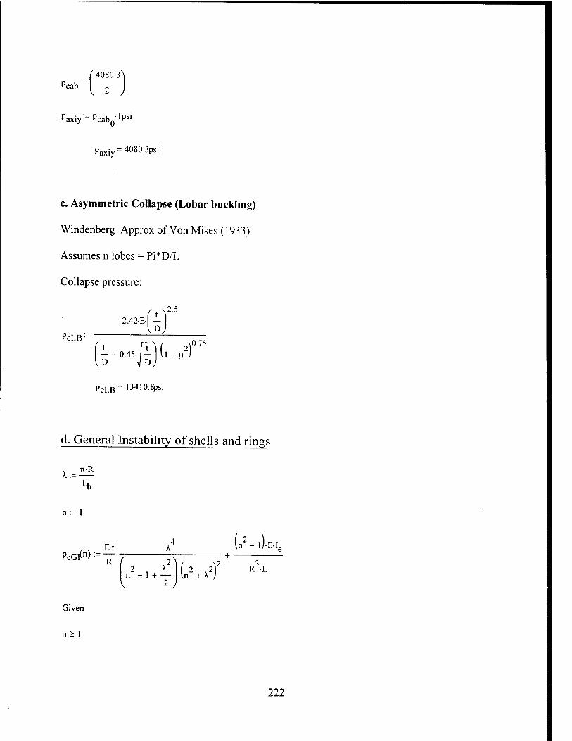
Pcab I 2 ,
Paxiy^PcabQ-'P5'
Paxiy = 4080.3psi
c. Asymmetric Collapse (Lobar buckling)
Windenberg Approx of Von Mises (1933)
Assumes n lobes = Pi*D/L
Collapse pressure:
2.42-E-
PcLB:= D
2.5
o.ji).(,vr ^D
pcLB= 13410.8psi
d. General Instability of shells and rings
*:= 7I-R
n:= 1
PcGl(n):=Y7 (n2-,).E,
2 , X n - 1 + — .(„2 + rf R3L
Given
n> 1
222
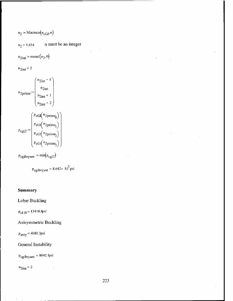
n2 := Minimiz^pcQj,nj
n7 = l .654 n must be an integer
n2int:= round (n2,0)
^int:
12prime'
Sinf1^ n2int
n2int + ]
Vn2int+2
^PcG(n2prim^A
Pcsi2 :-
PcG/n2primej
PcGlfn2prim^
PcGlTn2pr ne.
Pcgibryant :~ m'lr\Pcgi2!
Pcgibryant = 8642x ^Psi
Summary
Lobar Buckling
pcLB= 13410.8psi
Axisymmetric Buckling
Paxiy=4080-3Psi
General Instability
Pcgibryant = 8642.1psi
^int:
223

This page intentionally left blank
224
Related Documents