DEVELOPMENT TECHNOLOGY UNIT Working Paper No 33 Comparison Between DTU and Commercial Hydraulic Ram Pump Performance Development Technology Unit, Department of Engineering, Warwick University, Coventry CV4 7AL Tel: (0) 203 523122 Fax: (0) 203 418922 Telex: 311904 UNIVWK G

Welcome message from author
This document is posted to help you gain knowledge. Please leave a comment to let me know what you think about it! Share it to your friends and learn new things together.
Transcript
DEVELOPMENT TECHNOLOGY UNIT
Working Paper No 33
Comparison Between DTU and Commercial Hydraulic Ram Pump Performance
Development Technology Unit, Department o f Engineering,
W arwick University, Coventry CV4 7AL
Tel: (0) 203 523122 Fax: (0) 203 418922 Telex: 311904 UNIVWK G
DTU Working paper No.33 1992Comparison between DTU and Commercial Ram
Hydraulic Ram Pump Performances
UPDATE AND COMMENTS/ APRIL 1996Since this paper was written, the DTU Mark 6.4 pump has been phased out, to be replaced by first the M8.4 and more recently the S2. All these are pumps normally run with a 2" G.I. drivepipe and delivering to up to 100m using a drive flow of 40 to 120 litres/min. Preliminary results for the M8/S2 on a single setting are given at the end of this paper, indicating that, setting for setting, the M8 is superior to its predecessors. Generally the DTU later models are more efficient than the M6. Of course performance as measured in this paper is only part of the story. The DTU pumps are made largely of mild steel and are therefore more subject to corrosion than most 'commercial' machines. In recent years there has been a trend towards use of plastics in ram pumps as pvc or ABS piping replaces galvanised iron. However plastic pumps can rarely operate reliably at delivery heads exceeding 40 meters. There is also a growing interest in providing the air-cushioning of the output via an enclosed air packet {for example closed cell foam) instead of an air vessel with a free air-water surface. This arrangement can effectively increase the usable drive head by allowing the impulse valve exhaust to emerge under water.In the paper, the early comparisons with commercial pumps use data from a study by T H Delft which were obtained from slightly larger models (from the respective manufacturers' ranges), and with a much higher drivehead, than the comparisons in the rest of the paper.Details of the current (1996) DTU designs, namely SI (for use with a 1" steel drivepipe), S2 (2" steel) and P90 (90 mm. pvc) are given in DTU Technical Releases TR11, TR14 and TR12 respectively.
CONTENTS Page No.
1. INTRODUCTION 1
1.1 D e lf t U n iv e r s i ty 1
1 .2 DTU, U n iv e rs i ty o f Warwick 1
2 . SUMMARY OF WORK CARRIED OUT AT DELFT
2 .1 S e le c t io n o f Pumps 2
2 .2 A ssessm ent o f E x perim en ta l P ro ced u re 4
2 .3 Summary o f R e s u lts 6
2 .4 C o n c lu sio n s about Commercial Pumps 7
2 .5 Non-D im ensional Com parison 10
3 . SUMMARY OF DTU TESTS
3.1 E x p erim en ta l R ig and P ro ced u re 10
3 .2 Pump T uning 10
3 .3 Sunmary o f T es t R e s u lts 12
4 . COMPARISON OF DTU AND COMMERCIAL PUMPS
4 .1 P roblem s in Com parison 17
4 .2 E f f ic ie n c y Com parisons 17
4 .3 Power Com parison 19
5 . COST COMPARISON 19
6 . SUMMARY OF CONCLUSION 22
A ppendix A CONTINUING DTU PUMP DEVELOPMENT 25
A ppendix B TABLES OF PERFORMANCE RESULTS 28
A ppendix C FURTHER NOTES AND COMMENTS ON THE WORK AT DELF 33
T.D.Jeffery April 1991
Li s t o f Tables Page No.
T ab le 1 Com parison o f Commercial H y d rau lic Rams 3
2 C ost Com parison o f Commercial Rams 4
3 H y d rau lic Rams S e le c te d by D e lf t 5
4 Summary o f D e lf t T e s t R e s u lts 6
5 Summary o f DTU M6.4 T e s t R e s u lts 7
L i s t o f G raphs
Graph I E f f ic ie n c y o f Commercial Pumps 8
2 Power o f Commercial Pumps 9
3 R a tio o f Commercial Pumps 11
4 E f f ic ie n c y o f DTU M6.4 14
5 Power o f DTU M6.4 15
6 R a tio o f DTU M6.4 16
7 E f f ic ie n c y Com parison o f DTU w ith Commercial Pumps 18
8 Power Com parison o f DTU w ith Commercial Pumps ’ 20
9 R a tio Com parison o f DTU w ith Commercial Pumps 23
10 E f f ic ie n c y Com parison o f M6.4 and M8.4 26
11 Power Com parison o f M6.4 and M8.4 27
L is t o f F ig u re s
F ig u re 1 DTU ex p e rim en ta l r ig 12

l. INTKQBUCnQJi
This paper details the performance of the DTU Marie 6.4 hydraulic ram pump in comparison to commercial models run under similar conditions. Details of the performance of a number of commercial pumps tested at Delft University, Netherlands arc used for comparisoa
1.1 Delft University
Between 1982 and 1984 J. Tacke of Delft University of Technology carried out tests on a number of commercially available hydraulic ram pumps. These were published in 1988 with comprehensive details of all results obtained and the development of a mathematical model for prediction of ram performance. As part of this programme Field tests were conducted by the Foundation of Dutch Volunteers in Rwanda. These aimed to investigate the technical performance and durability under operating conditions in a community setting, social acceptance and community panicipation in installing, operating and maintaining a hydraulic ram system.
The presentation by Delft of all laboratory test results is excellent and allows a good level of comparison for tests on subsequent designs. Unfortunately no details of the findings or conclusions resulting from the field trials in Rwanda are made available. However the DTU are greatly indebted to Delft for their provision of such a useful resouce.
1.2 DTU. University of Warwick
The Development Technology Unit has been investigating hydraulic ram pump design, performance and manufacture since 1985. This began with student projects and has grown into a full-time research programme largely funded by the Overseas Development Administration. The aims of the programme are:'
a) to analyse in detail the operation of the ram pump gaining a comprehensive understanding of the operating principles and complex hydraulic interactions occuring within the pump.
b) to produce pump designs suitable for manufacture in developing countries using available materials and production processes.
c) to thoroughly test such designs for their performance and endurance (including extensive field trials) and offer findings for widespread dissemination.
d) to develop and prove methods for surveying and design of complete water supply installations.
e) to produce design charts and computer based tools to enable design and field engineers to confidently include hydraulic ram pumps as an option in their water supply schemes.
f) to provide technical expertise and training for two African based programmes installing ram pumps for village water supply and irrigation.
In terms of hardware development the DTU has two distinct working areas. The first is the development of designs of steel hydraulic ram pumps based on the 2" diameter BSP pipe that has been found to be widely available in developing countries and is of an appropriate capacity for small village water supply schemes. The second area of hardware development is the production of plastic hydraulic ram pumps based on widely available 110mm plastic pipe and especially suitable for irrigation close to water courses. Rough specifications and performance indications are given below.
- 1 -
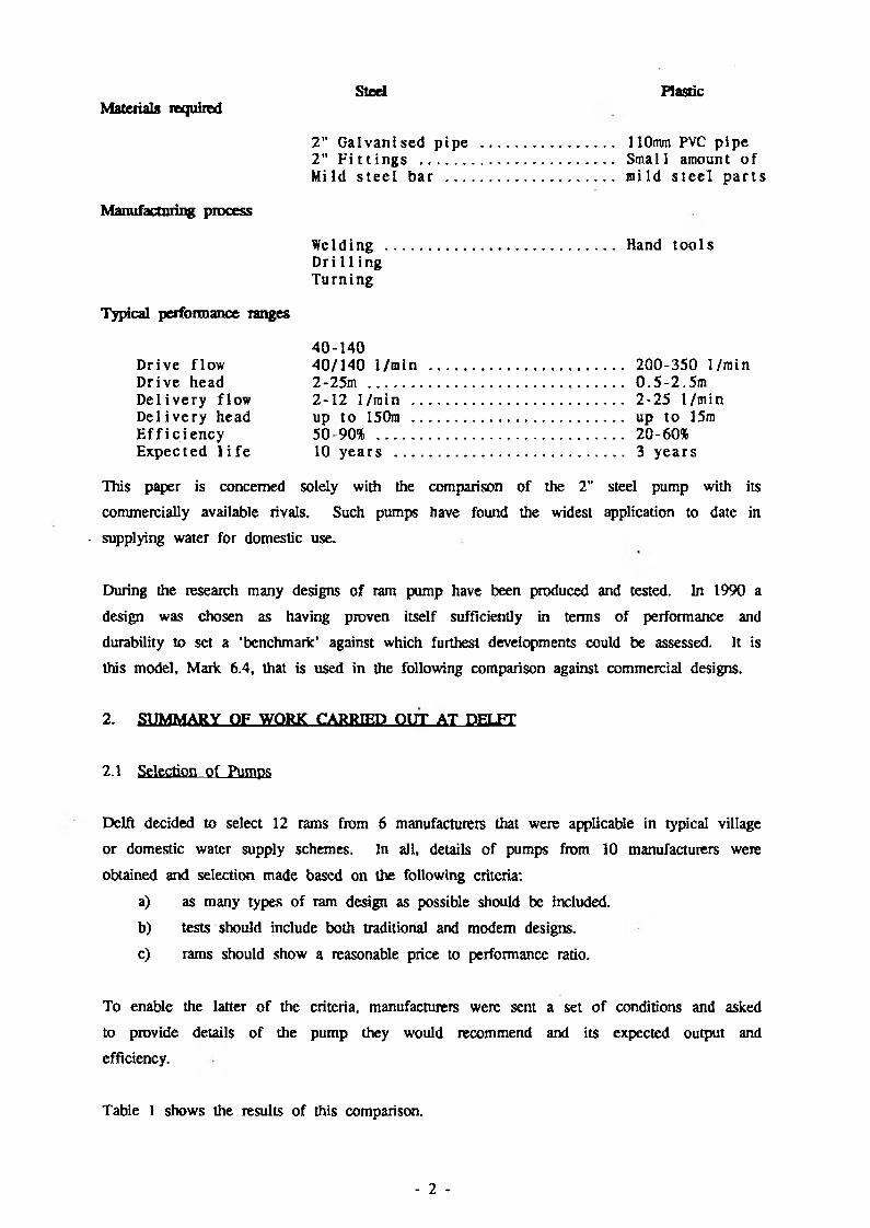
Steel PlasticMaterials required
2" G a lv an ised p ip e ................................... 110mm PVC p ip e2" F i t t i n g s ................................................... Small amount o f
M ild s te e l b a r ............................................ m ild s te e l p a r t s
Manufacturing process
W elding ............................................................ Hand to o lsD ri1 1ing T urn ing
Typical performance ranges
40-140D rive flow 40/140 I/m in ................................................... 200-350 I/m inD rive head 2-25m ................................................................... 0 . 5 - 2 . 5mD e liv e ry flow 2-12 1/min ........................................................ 2*25 1/m inD e liv e ry head up to 150m ........................................................ up to 15mE ff ic ie n c y 5090% ................................................................. 20-60%E xpected l i f e 10 y e a rs ............................................................ 3 y e a rs
This paper is concerned solely with the comparison of the 2" steel pump with its
commercially available rivals. Such pumps have found the widest application to date in
• supplying water for domestic use.
During the research many designs of ram pump have been produced and tested. In 1990 a
design was chosen as having proven itself sufficiently in terms of performance and
durability to set a ‘benchmark’ against which furthest developments could be assessed. It is
this model, Mark. 6.4, that is used in the following comparison against commercial designs.
2. SUMMARY OF WORK CARRIED OUT AT DELFT
2.1 Selection of Pumps
Delft decided to select 12 rams from 6 manufacturers that were applicable in typical village
or domestic water supply schemes. In all, details of pumps from 10 manufacturers were
obtained and selection made based on the following criteria:
a) as many types of ram design as possible should be included.
b) tests should include both traditional and modem designs.
c) rams should show a reasonable price to performance ratio.
To enable the latter of the criteria, manufacturers were sent a set o f conditions and asked
to provide details o f the pump they would recommend and its expected output and
efficiency.
Table 1 shows the results o f this comparison.
- 2 -
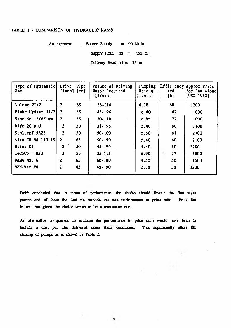
TABLE 1 - COMPARISON OF HYDRAULIC RAMS
Arrangement: Source Supply = 90 I/m in
Supply Head Hs = 7.50 m
Delivery Head hd = 75 m
Type o f H y d ra u lic Ram
D rive[ in c h ]
P ipe[mm]
Volume o f D riv in g W ater R equired
[1 /m in]
Pumping R ate q
[ I /m in i
E f f ic ie n c yt r d[%]
Approx P r ic e fo r Ram Alone [USS-I982]
V ulcan 2 1 /2 2 65 36-114 6 .1 0 68 1200
B lake Hydram 31 /2 2 65 45- 96 6 .0 0 67 1000
Sano No. 5 /6 5 mm 2 65 50-110 6 .9 5 77 1000
R ife 20 HDU 2 50 38- 95 5 .4 0 60 1100
Schlum pf 5A23 2 50 50-100 5 .5 0 61 2700
A lto CH 66-110-18 2 65 50- 90 5 .4 0 60 2100B ria u D4 2 50 45- 90 5 .4 0 60 3200CeCoCo - H50 2 50 25-115 6 .9 0 77 3500VAMA No. 6 2 65 60-100 4 .5 0 50 1500BZH-Ram W6 2 65 45- 90 2 .7 0 30 1200
Delit concluded that in terms of performance, the choice should favour the first eight
pumps and o f these the first six provide the best performance to price ratio. From the
inform anon given the choice seems to be a reasonable one.
An alternative comparison to evaluate the performance to price ratio would have been to
include a cost per litre delivered under these conditions. This significantly alters the
ranking of pumps as is shown in Table 2.
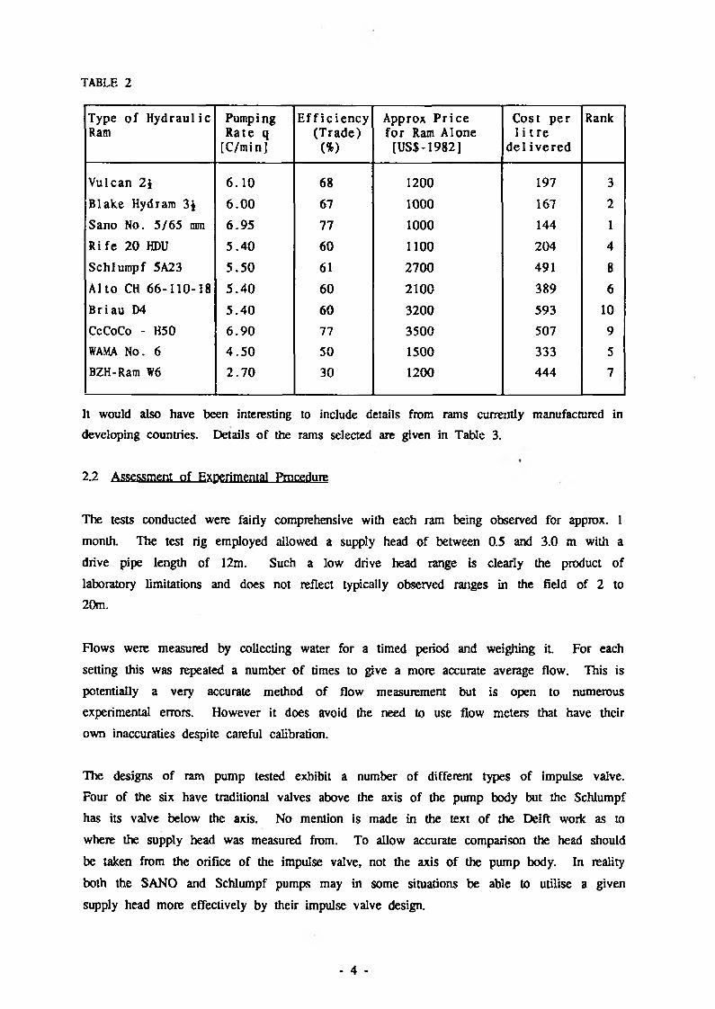
TABLE 2
Type o f H y d rau lic Ram
Pumping R ate q
[C/minJ
E f f ic ie n c y(T rade)
(%>
Approx P r ic e fo r Ram Alone
[US$-I982]
Cost p e r 1 i t r e
d e l iv e re d
Rank
V ulcan 2 \ 6 .1 0 68 1200 197 3
B lake Hydram 3J 6 .0 0 67 1000 167 2
Sano No. 5 /65 mm 6.9 5 77 1000 144 1
R ife 20 HDU 5 .4 0 60 1100 204 4
Schlum pf 5A23 5 .5 0 61 2700 491 8
A lto CH 66-110-18 5 .4 0 60 2100 389 6
B riau D4 5 .4 0 60 3200 593 10CeCoCo - H50 6 .9 0 77 3500 507 9
WAMA No. 6 4 .5 0 50 1500 333 5BZH-Ram W6 2 .7 0 30 1200 444 7
It would also have been interesting to include details from rams currently manufactured in
developing countries. Details of the rams selected are given in Table 3.
2.2 Assessment of Experimental Procedure
The tests conducted were fairly comprehensive with each ram being observed for approx. 1
month. The test rig employed allowed a supply head of between 0.5 and 3.0 m with a
drive pipe length of 12m. Such a low drive head range is clearly the product of
laboratory limitations and does not reflect typically observed ranges in the field of 2 to 20m.
Flows were measured by collecting water for a timed period and weighing it. For each
setting this was repeated a number o f times to give a more accurate average flow. This is
potentially a very accurate method of flow measurement but is open to numerous
experimental errors. However it does avoid the need to use flow meters that have their
own inaccuraties despite careful calibration.
The designs of ram pump tested exhibit a number of different types of impulse valve.
Four of the six have traditional valves above the axis of the pump body but the Schlumpf
has its valve below the axis. No mention is made in the text of the Delft work as to
where the supply head was measured from. To allow accurate comparison the head should
be taken from the orifice of the impulse valve, not the axis of the pump body. In reality
both the SANO and Schlumpf pumps may in some situations be able to utilise a given
supply head more effectively by their impulse valve design.
- 4 -
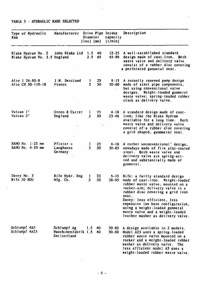
TABLE 3 - HYDRAULIC RAMS SELECTED
Type o f H y d rau lic Ram
M an u fac tu re r D rive P ip e In ta k e D e s c r ip t io n D iam eter cap ac i ty
[ in s ] [ran] [1 /m in]
B lake Hydram No. 2 John B lake L td 1 .5 40 B lake Hydram No. 3 .5 England 2 .5 65
12-25 A w e l l - e s t a b l i s h e d s ta n d a rd 45-96 d e s ig n made o f c a s t - i r o n . Both
w aste v a lv e and d e l iv e r y va lv e c o n s is t o f a rubber d is c co v erin g
a p e r f o r a te d gunm etal s e a t .
A lto J 26 -8 0 -8 A lto CH 50-110-18
J.M . D esclaud 1 25 8-15 F ra n c e 2 50 30-60
A r e c e n t ly renewed pump d es ig n made o f s t e e l p ip e com ponents, b u t u s in g c o n v e n tio n a l v a lv e d e s ig n s . W eig h t-lo ad ed gunmetal w aste v a lv e ; s p r in g - lo a d e d rubber c l a c k as d e l i v e r y v a l v e .
Vulcan 1" Vulcan 2"
Green & C a r t e r 1 25 4-18 England 2 50 23-46
A s t a n d a r d d e s ig n made o f c a s t - i r o n ; l i k e the Blake Hydram a v a i l a b l e fo r a long t ime. Both was te v a l v e and d e l i v e r y va lve c o n s i s t o f ' a rubber d i s c cover ing a g r i d shaped , gunmmetal s e a t .
SANO No. 1-25 mm SAN0 No. 4 -50 mm
P f i s t e r + Langhanss Ge rmany
1 25 6-16 A r a t h e r u n c o n v e n t i o n a l ’ d e s ig n ,2 50 30-65 nowadays made o f f i r e z i n c - c o a t e d
s t e e l . Both waste v a lv e and d e l i v e r y v a lv e a r e s p r i n g - a c t - ted and s u b s t a n t i a l l y made o f g u n m e ta l .
Davey No. 3 R i fe 20 HDU
R i f e Hydr. Eng I 25 5-15 R i f e : a f a i r l y s t a n d a r d des ign Mfg. Co. 2 50 38-95 made o f c a s t - i r o n . Weight - loaded
rubber waste v a l v e , mounted on a rocker -a rm ; d e l i v e r y v a lv e i s a rubber d i s c c o v e r in g a g r i d i ron s e a t .Davey: l e s s e f f i c i e n t , l e s s e xpens ive low base c o n f i g u r a t i o n , u s in g a w e ig h t - lo a d e d gunmetal waste v a l v e and a w e ig h t - lo ad ed l e a t h e r washer as d e l i v e r y va lve .
Schlumpf 4A5 Schlumpf 4A23
Schlumpf Ag 1.5 40 30-60 M as c h in e n fa b r ik 1.5 40 30-60 Swi t z e r l a n d
A d es ig n a v a i l a b l e in 2 models . Model A23 u s es a s p r in g - l o a d e d rubber waste v a lv e mounted on a rocker and a w e ig h t - l o a d e d rubber washer as d e l i v e r y v a l v e . The l e s s e f f i c i e n t model A5 u ses a w e ig h t - lo a d e d ru b b er waste va lve .
- 5 -
The laboratory experiments also included the use of piezo-electric pressure transducers,
displacement transducers and strain guages to observe in detail the changes occuring.
Although the resolution o f these observations is low they are well presented and provide
useful insights into pump operation.
The major criticism of the information presented by Delft is that they supply no indication
of how each pump was setup when the results were taken. They simply state that ‘waste
valve adjustment’ was ‘kept constant’ over the whole range of tests. To ensure a fair
comparison the waste valves were presumably initially adjusted to the manufacturers
recommendation that would give the best overall performance (efficiency and power output)
under typical operating conditions. If this was not the case then the results are practically
worthless as some of the pumps may have been badly tuned whilst others were well tuned
for the given operating conditions.
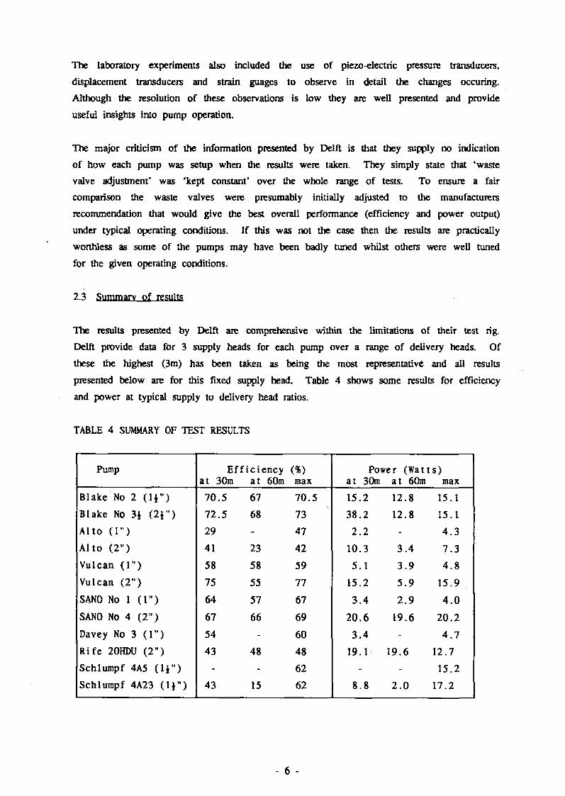
2.3 Summary o f results
The results presented by Delft are comprehensive within the limitations of their test rig.
Delft provide data for 3 supply heads for each pump over a range of delivery heads. Of
these the highest (3m) has been taken as being the most representative and all results
presented below are for this fixed supply head. Table 4 shows some results for efficiency
and power at typical supply to delivery head ratios.
TABLE 4 SUMMARY OF TEST RESULTS
Pump E f f i c i e n c y a t 30m a t 60m
<%)max
Power (W at ts ) a t 30m a t 60m max
Blake No 2 ( H " ) 70.5 67 70 .5 15.2 12.8 15.1
Blake No 3* ( 2 D 72.5 68 73 38.2 12.8 15.1
A l to (1") 29 - 47 2 .2 - 4 .3
A l to (2 " ) 41 23 42 10.3 3 .4 7 .3Vulcan (1" ) 58 58 59 5.1 3 .9 4 .8Vulcan ( 2 ” ) 75 55 77 15.2 5 .9 15.9SANO No 1 (1" ) 64 57 67 3 .4 2 . 9 4 . 0
SANO No 4 (2" ) 67 66 69 20.6 19.6 20 .2
Davey No 3 ( 1 ” ) 54 - 60 3 .4 - 4 . 7
R i fe 20HDU (2" ) 43 48 48 19.1 19.6 12.7
Schlumpf 4A5 ( l j w) - - 62 - - 15.2
Schlumpf 4A23 (1 * “ ) 43 15 62 8 .8 2 . 0 17.2
- 6 -

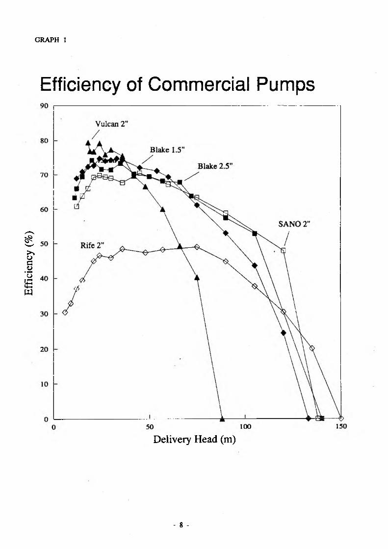
Five of the pumps tested are of similar specification to the DTU models and were therefore
selected for analysis and comparison. Graphs 1 and 2 show power and efficency curves
for these five pumps. The large variations between pumps can be seen quite clearly and
comparison is complicated by the marked differences in the power and efficiency curves.
At low heads for instance the Vulcan 2" ram is the most efficient but has the lowest
output power and will only run up to a delivery head of 85 m.
2.4 Conclusions about commercial pumps
Delft offer no conclusions or direct comparisons between the various pumps tested. The
results are complex and comparison has to be based on many factors in order to produce
sensible recommendations. In any given situation the exact requirements will vary. The
points given below are an attempt to pick out the main items in order to draw some
conclusions.
1) The Vulcan 2" has the highest efficiency recorded at 76.9% and at low heads (up to
36 m) has the best effiency of all the pumps.
2) The Rife 2" has the lowest efficiency up to 70 m and never increases over 50%.
However it has the widest range of delivery heads over which it will operate. Overall
it would be fair to say that the Rife pump has the poorest efficiency.
3) Overall the Blake 2 i" is the most efficient closely followed by the smaller Blake 1J".
They show good efficiencies over the normal operating range and will pump over a
wide range o f delivery heads.
4) Similarly the SANO 2" show's good efficiencies over a wide range of delivery heads
and is more efficient than the Blake pump over about 75 m.
5) The Vulcan 2" has the lowest power output over its small range of delivery heads.
6) Blake is clearly the most powerful pump over its entire range.
7) At low delivery heads (up to 75 m) the SANO 2” has a slightly higher output than
the Rife 2” which above 75 m is better. However there is little to choose between them over the complete range o f operation.
8) Attempting to combine both power and efficiency it would seem reasonable to conclude
that the Blake 2 j ” offers the best overall performance. Of the remainder the SANO
2" would seem to be the best compromise.
Effic
ienc
y (%
)GRAPH i
Efficiency of Commercial Pumps
Delivery Head (m)
- 8 -

Powe
r (W
)GRAPH 2
0 50 100 150
Delivery Head (m)
- 9 -
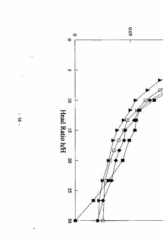
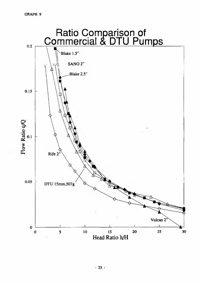
2.5 Non-Dimensionai Comparison
Delft use a further means of pump comparison by graphically presenting the ratio of
delivery 10 supply flow (q/Q) over a range of delivery to supply head (h/H) ratios. Thus a
non dimensional comparison between pumps is possible. For any given head ratio the
greater the ratio of flows the better the perfoimace of the pump. Graph 3 shows these
ratio curves for the five pumps chosen. Only two conclusions can sensibly be drawn from
this comparison:
1) The Rife 2" is notably worse than all its rivals.
2) There is little to choose between all of the other makes of pump.
Despite this lack of obvious conclusions the ability to compare pumps using non
dimensional parameters may prove valuable.
3. SUMMARY OF DTU TESTS
3.1 Experimental rig and procedure
The DTU has established performance testing rigs at the University to allow comprehensive
analysis of prototype pumps. The major restrictions imposed by the rigs location are:
i) drive pipe length - limited to 10.5 m and horizontal
ii) drive head - restricted to 2, 3, 4 or 5 m
The delivery head is controlled using a needle valve providing an accurately variable orifice
over which the desired head can be dropped (measured by a pressure guage). Both drive
and delivery Hows are measured by float type flow meters for fast and accurate readings.
For their tests Delft used three drive head setting, 1, 2 and 3 m. However for comparison
between DTU and commercial pumps only one drive head was chosen (3.0 m).
3.2 Pump Tuning
The DTU pump design selected for testing was the Marie 6.4 which typically uses a 2"
BSP drive pipe but also runs using I j" pipe (see Figure 1). As the Delft work gives no
clear indication of how pumps were tuned a series of results were recorded using different
settings of the impulse valve. Low stroke, low weight settings generally give high
efficiency and low power output Up to a point it is also true to say that high stroke,
t A

GRAPH 3
Commerc'al Pum,
H e a d R a t i o h / U 2°
* 11 .

high weight settings give low efficiency and high output power.
Choosing which of these results are used to compare against the Delit ones is dealt with in
Section 4.1.
Figure 1
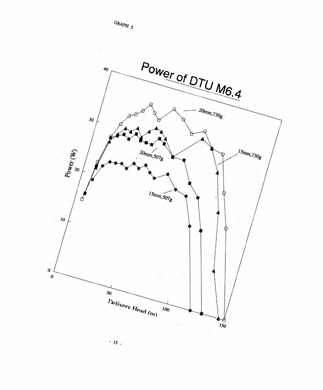
3.3 Summary of test results
Table 5 gives a selection of results for identical conditions as those in Table 4 for the commercial pumps.
Graphs 4 and 5 show the variation in efficiency and power over the full range of potential delivery heads.
Graph 6 presents the non dimensional flow ratio to head ratio curves for these results.
- 12 -

The design o f the M6.4 pump allows it to be tuned to suit a wide range of flow and head
conditions, making one model applicable to many sites. The results show the wide range
of efficiency and power obtainable under these given conditions and emphasize how
important tuning can be. If drive water is limited then peak efficiency will be required to
make best use of that available. If there is plenty o f drive water pumps should be tuned
to give maximum power output despite the lower efficiency of such a setting.
It is clear that both good efficiency and power are obtainable over a broad range of
delivery heads and that the pump is capable of operating at very high head ratios.
The stroke o f teh M6.4 design can range between 5 mm 40 mm with infinite adustment
between these limits. The minimum weight of the valve assembly is 507g comprising the
plug, stem, nuts etc. although recent modification to the pump enables further reduction.
Maximum weight is limited by the physical dimensions but lOOOg should be considered as
the upper limit.
The results show for just a few combinations of stroke and weight how the efficiency and
power output characteristics o f the pump can be dramatically altered. Low stroke and
weight give high efficiency but low power over a limited range of delivery heads whereas
high stroke and weight give lower efficiency but high power output ovei* a wider possible
range of heads. Tuning of the pump to best suit any particular set of conditions is a
complicated process to explain and is dealt with in other DTU literature.
TABLE 5 SUMMARY OF DTU M6.4 TEST RESULTS
Pump S e t t i n g s Dr ive P ipe S t r o k e Length D ia ( " ) (mm)
Weight(g)
E f f i c i e n c y a t 30m a t 60m max
Power a t 30m a t 60m max
1) 1.5 10 507 68 83.3 88 .9 16.7 17.2 18.32) 1.5 15 507 59 .7 64.8 6 8 .7 22 .6 22 .6 24 .6
3) 1.5 20 507 50 54.7 60 .4 24 .5 25 .5 28.1
4) 2 10 507 66.7 82 .2 82 .2 15.7 18.1 18.1
5) 2 15 507 63 .2 70 .8 74 .2 2 3 .5 22 .6 24 .5
6) 2 20 507 58 62.5 65 .9 2 8 .5 29 .4 30.17) 2 10 730 67.1 77.8 82 .6 24 24 27 .5
8) 2 15 730 59 .8 61.4 73 .3 30 .2 30 .4 32.4
9) 2 20 730 51 .9 58 .7 6 1 .6 33 .4 36 .3 36.3
- 13 -

C R A P H 4
O liver*, r» l°0
* 14 .
G* * P H s
0\Xa>Q*
soo

Flow Ratio q/Qo ©
►—» iv»Oto
Q
33CT\Ratio Graph for DTU M6.4

4. w J J i PARISON OF PTU AND COMMERCIAL PUMPS
4.1 Problems in comparison
There are inevitably problems and potential inaccuracies in taking data from two separate
sets of tests carried out on two different test rigs. The main areas of difficulty are
outlined below along with some explanation o f their significance and potential methods for
overcoming them.
a) The drive pipe lengths o f the two test rigs differ by 1.5 m with the Delft rig using
an inclined pipe whereas the Warwick tests use a horizontal one. The length of the
drive pipe o f a hydraulic ram pump system affects (among other things) the time taken
for pressure waves to traverse the length of the pipe, total friction in the system and
the energy available for pumping. The exact effects of these parameters on pump
performance are complicated to evaluate and given the relatively small difference can be assumed to have no major effect for the purposes of this comparison.
b) As has already been mentioned, the Delft work is unclear about the tuning of each of
the pumps tested, other than the fact that they were left constant throughout testing
once installed. To allow a sensible comparison it has been assumed that the
commercial pumps tested by Delft were each set to some recommended point that gave
a reasonable efficiency and power output across a broad range of conditions. In order
to compare the DTU pump a best average setting from those taken has been chosen
and also comparisons of the optimum settings for efficiency and power. The setting
chosen for the general comparison is labelled as No. 5 in Table 5 using a standard 2"
drive pipe, a valve stroke of 15 mm and weight of 507 g.
4.2 Efficiency comparisons
The efficiency o f the DTU pump is of the same order as the better of the commercial
models. Graph 7 shows the chosen average and peak efficiency settings of M6.4 against the 5 commercial pumps.
In a typical operating range say 20-80 m the DTU average setting gives efficiencies ranging
between approx 63% and 74%. The DTU peak setting of those chosen returns results for
the same range between 64% and 83%. Detailing the comparison between these settings
and those for the commercial models is best don visually. The main points that can be drawn are:
- 17 -

Effic
ienc
y (%
)GRAPH 7
- 18 -

a) The Blakes machines have the best efficiency over the widest range o f delivery heads
with between 62% and 75% in the 20-80 m operating band. This is very similar the
DTU average setting although the shape of the curves is somewhat different giving
maximum and minimum efficiencies at different heads.
b) The DTU M6.4 pump has a markedly different efficiency profile from all the
commercial models with peak efficiency occurring at much higher heads.
c) The DTU M6.4 is capable of operating over a range of delivery beads as great as any
of the commercial models.
Separate tests to determine the peak efficiency of the M6.4 have shown that it is
capable of running at efficiencies of over 90%.
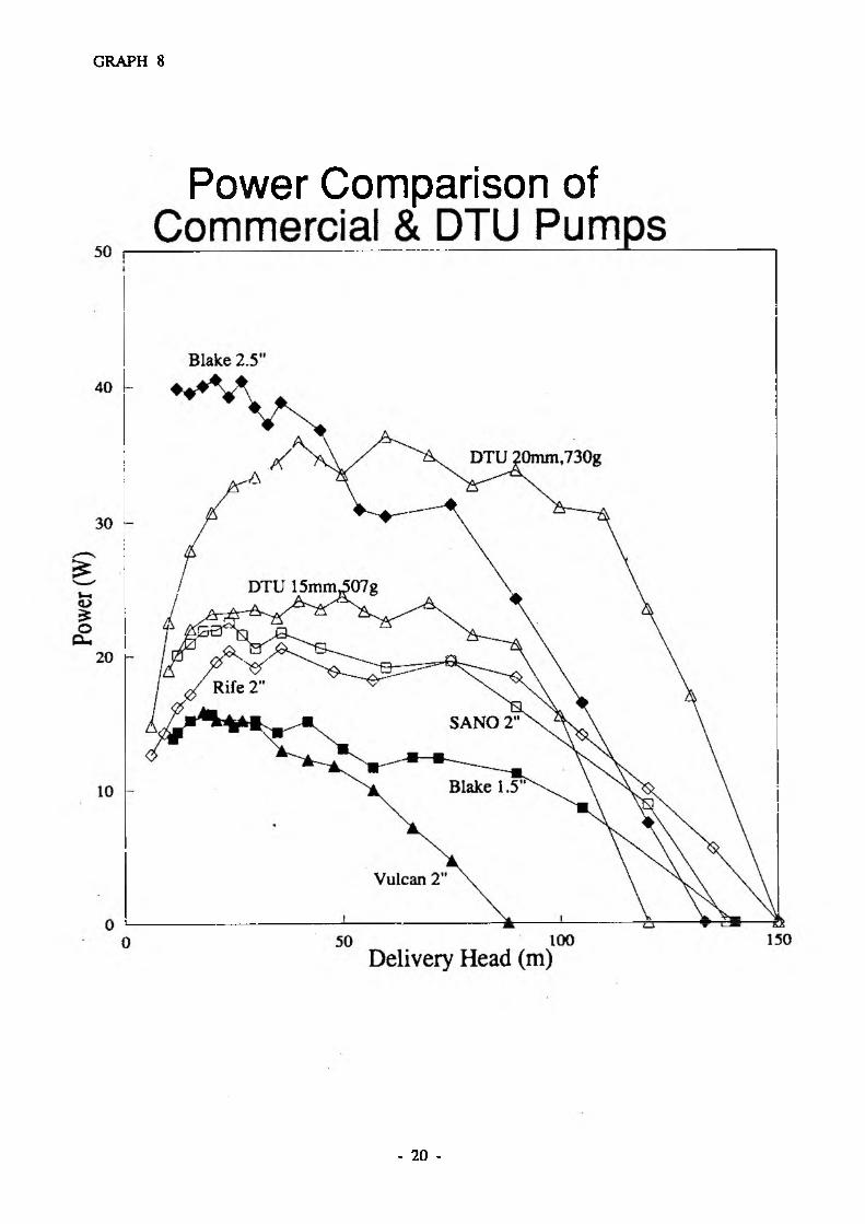
4.3 Power Comparison
Graph 8 shows the chosen average and peak power settings for the M6.4 against the 5
commercial pumps.
a) The average setting of the DTU M6.4 is clearly more powerful over a very wide
range o f delivery heads than 1̂1 of the commercial models of the same size. The
Blake 2±" model is clearly more powerful as should be expected from this
considerably larger capacity pump.
b) The peak setting of the M6.4 used gives power output similar to and, at higher heads,
better than even the Blake 2 i" model. Increased weight on the M6.4 would further
increase the power output although the limitation o f the pipe size and drive head
would probably limit peak power to around 40 watts.
5. COST COMPARISON
Table 2 in section 2.1 shows the costs of 10 rams in US$ in 1982 as given by Delft
These costs are for the pumps alone with no drive pipe, delivery pipe, shipping etc.
included, and range from US$ 1000 to 3500. No updated prices are available for
comparison with the DTU pump so an annual inflation rate of 5% has been assumed. A
comparative cost for the DTU pumps is hard to ascertain as they have only been
manufactured as one-off prototypes to date in the UK. The design of all the DTU pumps
is intended to allow manufacture in the country of use, avoiding any shipping and
importation problems but working to the constraints imposed in non-industrialised areas.
Power Comparison of
GRAPH 8
- 20 -
The Baptist Community of Western Zaire (CBZO) have a village water supply programme
installing the DTU M6.4 in its rural areas. Currently the manufacture of these pumps is
being contracted to a workshop in Kinshasa who are producing them in small batches as
requested. The total cost of these units in Zaire is approx. US$450 but once proper
manufacture has started it is estimated that this will reduce to $250-$300.
The actual cost to an end user in a developing country of a ram pump will include any
shipping and importation costs if it is made eslewhere. To accurately compare the DTU
pumps made in country with imported commercial models the costs associated with
transportation should be included. However such costs are so dependant upon the shipping
distance, customs duties etc. that they would be impossible to estimate with any accuracy.
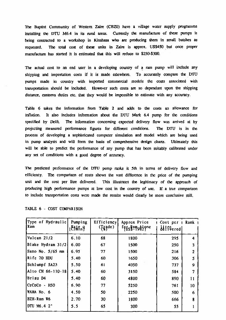
Table 6 takes the information from Table 2 and adds to the costs an allowance for
inflation. It also includes information about the DTU Mark 6.4 pump for the conditions
specified by Delft. The information concerning expected delivery flow was arrived at by
projecting measured performance figures for different conditions. The DTU is in the
process of developing a sophisticated computer simulation and model which are being used in pump analysis and will form the basis of comprehensive design charts. Ultimately this
will be able to predict the performance of any pump that has been suitably calibrated under
any set of conditions with a good degree of accuracy.
The predicted performance of the DTU pump ranks it 5th in terms of delivery flow and
efficiency. The comparison of costs shows the vast difference in the price of the pumping
unit and the cost per litre delivered. This illustrates the legitimacy of the approach of
producing high performance pumps at low cost in the country of use. If a true comparison
to include transportation costs were made the results would clearly be more conclusive still.
TABLE 6 - COST COMPARISON
Type o f H y d rau l ic Ram
Pumping
[ M f n ?
E f f i c i e n c y1
Approx P r i c e
f?6sSa,M i r e
r“ iCost p e r
U t t e r e d
■IRank i
Vulcan 21 /2 6 .10 68 1800 295 4Blake Hydram 31/2 6 .00 67 1500 250 3Sano No. 5 /65 mm 6.95 77 1500 216 2R i f e 20 HDU 5.40 60 1650 306 5Schlumpf 5A23 5 .50 61 4050 737 9A l to CH 66-110-18 5 .40 60 3150 584 7B r ia n D4 5 .40 60 4800 890 11CeCoCo - H50 6 .90 77 5250 761 10WAMA No. 6 4 .5 0 50 2250 500 6BZH-Ram W6 2 .7 0 30 1800 666 8DTU M6.4 2" 5 .5 65 300 55 1
6. SUMMARY OF CONCLUSION
The following points summarise the conclusions that can be drawn from these tests.
a) The DTU Mark 6.4 pump gives efficiencies comparable with the more efficient
commercial pumps over a wide range of condition.
b) The M.6.4 produces a higher output power than all commercial models of the same
size over a wide range of conditions.
c) The M6.4 has a cost to output ratio considerably lower than all of its commercial rivals.
The tests show that it is possible to produce simple and comparatively cheap hydraulic ram
pumps that can match and exceed the performance of commericial models. Whilst
endurance tests to date indicate that the DTU pumps are likely to exhibit adequate
durability no data is yet available for a long term comparison with commercial rivals. The
current design specification is to produce low maintenance pumps whose steel components
have a 10 year life and rubber components last approximately 6 months.
More detailed information concerning the design, manufacture, installation and performace of
DTU pumps is available on request.
- 22 -
Flow
Ratio
q/
Q
GRAPH
0.2
0.15 -
0.1 -
0.05 -
0 L 0
Ratio Comparison of Commercial & DTU Pumps
5 10 15 20 25 30
Head Ratio h/H
- 23 -

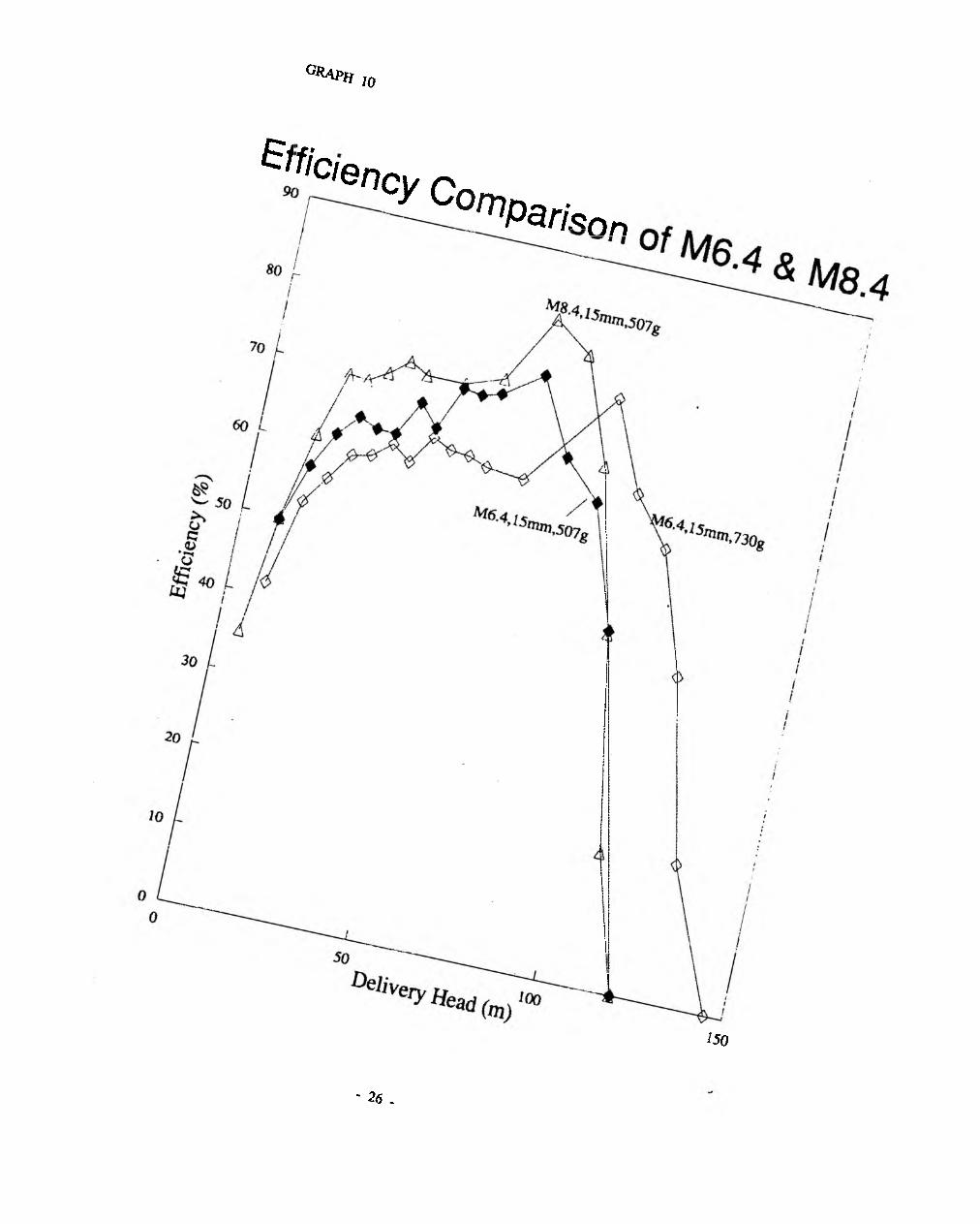
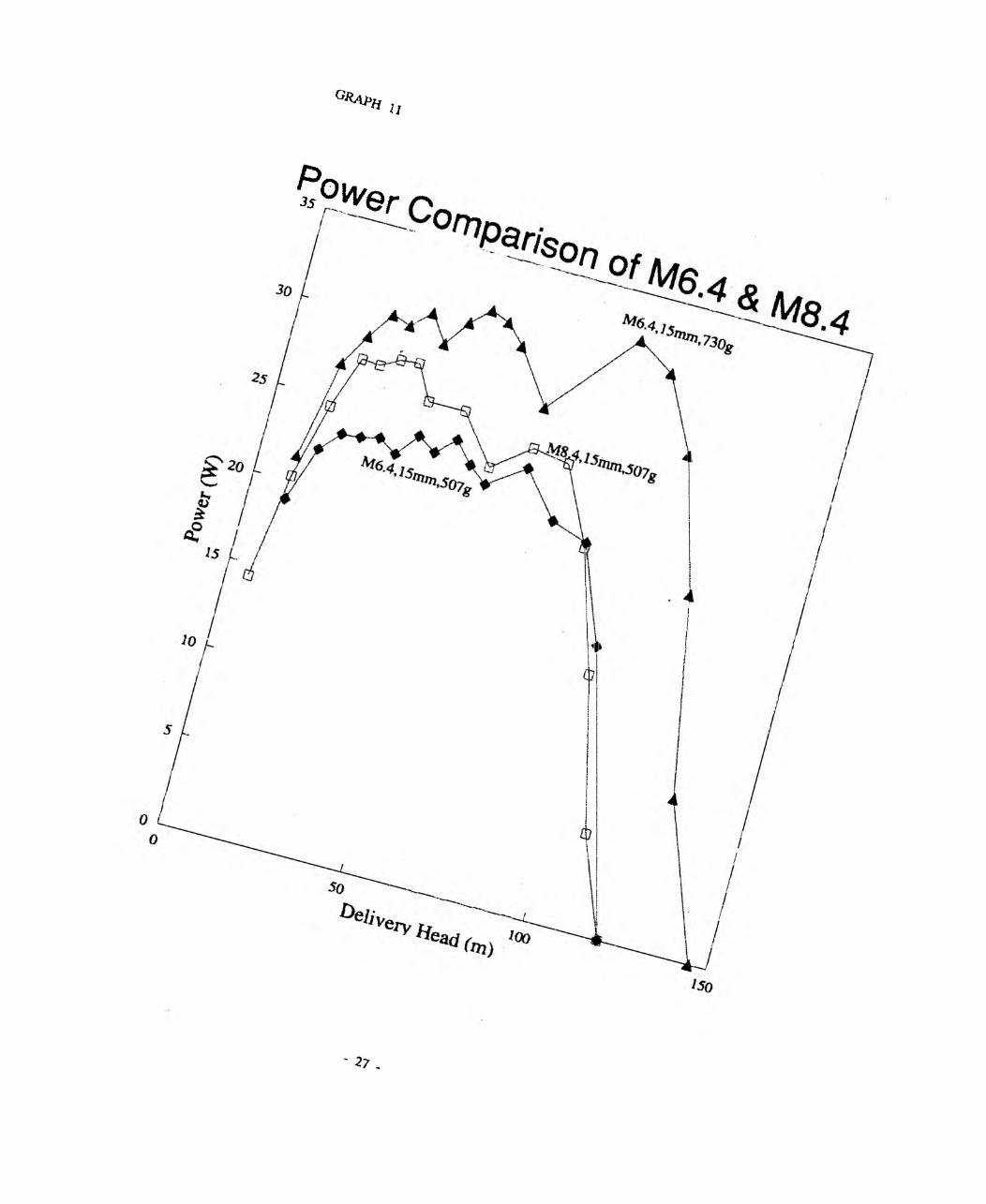
Appendix A CONTINUING DTU PUMP DEVELOPMENT
The Marie 6.4 pump was set as a DTU standard in 1990 to allow organisations interested
in using the pummp to have a standard model to woik with. Since that time a number of
developments have occurred in the on-going research programme and new design initiatives
produced. One such is the development of the Mark 8.4 that uses the same valves as the
M6.4 but replaces the 2" fittings used in the pump body witha body of 4" velded
construction. This alteration dramatically reduces the peak overpressure experienced the
system, damps out the high frequency oscillations experienced during the cycle and increases
both the efficiency and power output for any given set of conditions.
Graphs 10 and 11 allow comparison of the M8.4 with the M6.4 under identical conditions.
- 25 -
G ra p h 1 0
©»Clency ComPrison
150
' 26 .
q * a * h „
^°jver
' 2? ,
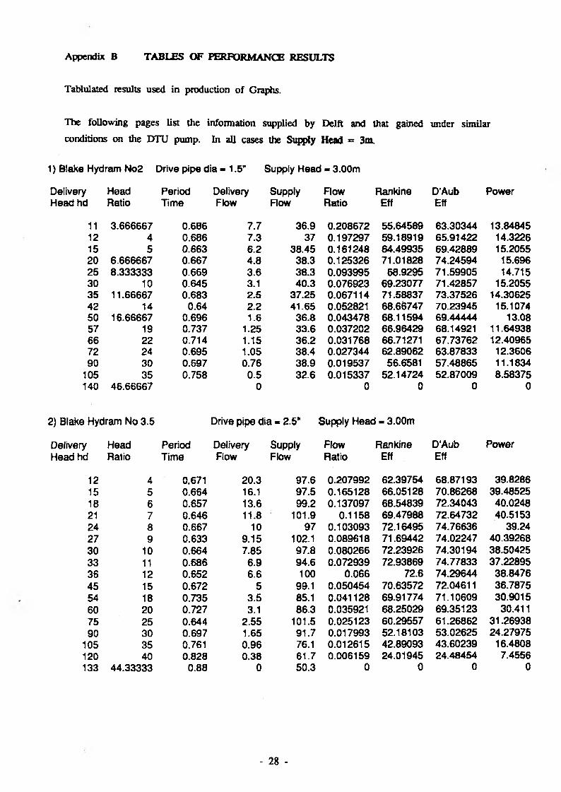
Appendix B TABLES OF PERFORMANCE RESULTS
Tablulated results used in production of Graphs.
The following pages list the information supplied by Delft and that gained under similarconditions on the DTU pump. In all cases the Supply Head = 3m.
1) Blake Hydram No2 Drive pipe dia - 1.5” Supply Head - 3.00m
Delivery Head Period Delivery Supply Flow Rankine D’Aub PowerHead hd Ratio Time Flow Flow Ratio Eff Eff
11 3.666667 0.606 7.7 36.9 0.208672 55.64589 63.30344 13.8484512 4 0.686 7.3 37 0.197297 59.18919 65.91422 14.322615 5 0.663 6.2 38.45 0.161248 64.49935 69.42889 15.205520 6.666667 0.667 4.8 38.3 0.125326 71.01828 74.24594 15.69625 8.333333 0.669 3.6 38.3 0.093995 68.9295 71.59905 14.71530 10 0.645 3.1 40.3 0.076923 69.23077 71.42857 15.205535 11.66667 0.683 2.5 37.25 0.067114 71.58837 73.37526 14.3062542 14 0.64 2.2 41.65 0.052821 68.66747 70.23945 15.107450 16.66667 0.696 1.6 36.8 0.043478 68.11594 69.44444 13.0857 19 0.737 1.25 33.6 0.037202 66.96429 68.14921 11.6493866 22 0.714 1.15 36.2 0.031768 66.71271 67.73762 12.4096572 24 0.695 1.05 38.4 0.027344 62.89062 63.87833 12.360690 30 0.697 0.76 38.9 0.019537 56.6581 57.48865 11.1834
105 35 0.758 0.5 32.6 0.015337 52.14724 52.87009 8.58375140 46.66667 0 0 0 0 0
2) Blake Hydram No 3.5 Drive pipe d ia - 2.5" Supply HeadI - 3.00m
Delivery Head Period Delivery Supply Flow Rankine D’Aub PowerHead hd Ratio Time Flow Flow Ratio Eft Eff
12 4 0.671 20.3 97.6 0.207992 62.39754 68.87193 39.828615 5 0.664 16.1 97.5 0.165128 66.05128 70.86268 39.4852518 6 0.657 13.6 99.2 0.137097 68.54839 72.34043 40.024821 7 0.646 11.8 101.9 0.1158 69.47988 72.64732 40.515324 8 0.667 10 97 0.103093 72.16495 74.76636 39.2427 9 0.633 9.15 102.1 0.089618 71.69442 74.02247 40.3926830 10 0.664 7.85 97.8 0.080266 72.23926 74.30194 38.5042533 11 0.686 6.9 94.6 0.072939 72.93869 74.77833 37.2289536 12 0.652 6.6 100 0.066 72.6 74.29644 38.847645 15 0.672 5 99.1 0.050454 70.63572 72.04611 36.787554 18 0.735 3.5 85.1 0.041128 69.91774 71.10609 30.901560 20 0.727 3.1 86.3 0.035921 68.25029 69.35123 30.41175 25 0.644 2.55 101.5 0.025123 60.29557 61.26862 31.2693890 30 0.697 1.65 91.7 0.017993 52.18103 53.02625 24.27975
105 35 0.761 0.96 76.1 0.012615 42.89093 43.60239 16.4808120 40 0.828 0.38 61.7 0.006159 24.01945 24.48454 7.4556133 44.33333 0.88 0 50.3 0 0 0 0
- 28 -
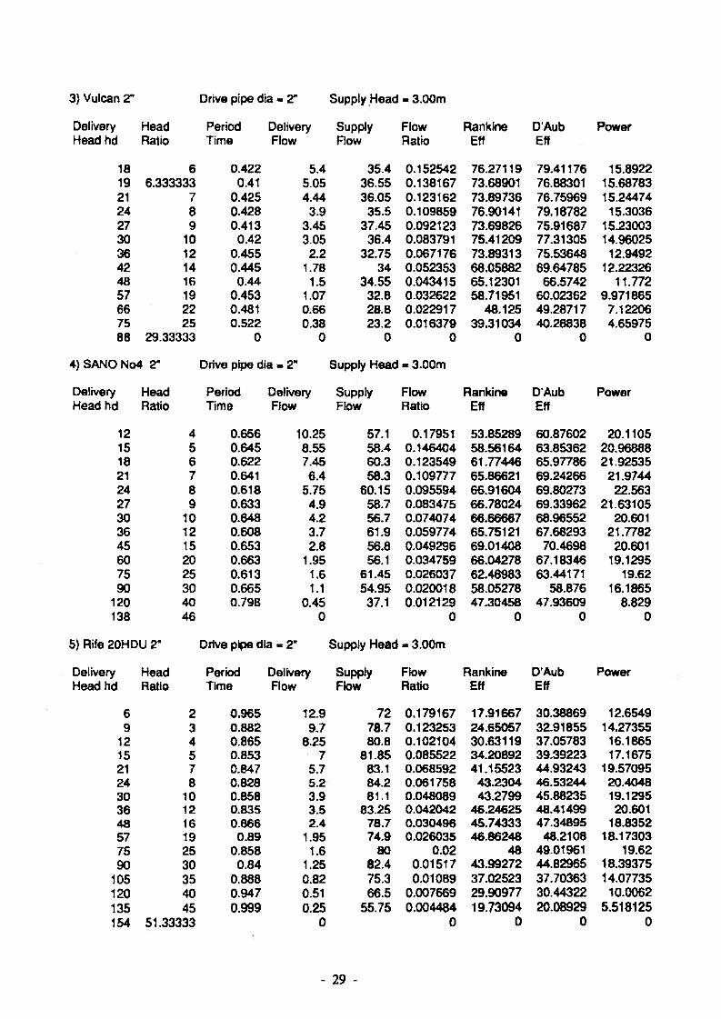
3} Vulcan 2" Drive pipe dia * 2" Supply Head - 3.00m
Delivery Head Period Delivery Supply Flow Rankfne D’Aufa PowerHead hd Ratio Time Flow Flow Ratio Eff Eff
18 6 0.422 5.4 35.4 0.152542 76.27119 79.41176 15.892219 6.333333 0.41 5.05 36.55 0.138167 73.68901 76.88301 15.6878321 7 0.425 4.44 36.05 0.123162 73.89736 76.75969 15.2447424 8 0.428 3.9 35.5 0.109859 76.90141 79.18782 15.303627 9 0.413 3.45 37.45 0.092123 73.69826 75.91687 15.2300330 10 0.42 3.05 36.4 0.083791 75.41209 77.31305 14.9602536 12 0.455 2.2 32.75 0.067176 73.89313 75.53648 12.949242 14 0.445 1.78 34 0.052353 68.05882 69.64785 12.2232648 16 0.44 1.5 34.55 0.043415 65.12301 66.5742 11.77257 19 0.453 1.07 32.8 0.032622 58.71951 60.02362 9.97186566 22 0.481 0.66 28.8 0.022917 48.125 49.28717 7.1220675 25 0.522 0.38 23.2 0.016379 39.31034 40.28838 4.6597588 29.33333 0 0 0 0 0 0 0
4) SANO No4 2" Drive pipe dia a 2" Supply Head - 3.00m
Delivery Head Period Delivery Supply Flow Rankine D’Aub PowerHead hd Ratio Time Flow Flow Ratio Eff Eff
12 4 0.656 10.25 57.1 0.17951 53.85289 60.87602 20.110515 5 0.645 8.55 58.4 0.146404 58.56164 63.85362 20.9688818 6 0.622 7.45 60.3 0.123549 61.77446 65.97786 21.9253521 7 0.641 6.4 58.3 0.109777 65.86621 69.24266 21.974424 8 0.618 5.75 60.15 0.095594 66.91604 69.80273 22.56327 9 0.633 4.9 58.7 0.083475 66.78024 69.33962 21.6310530 10 0.648 4.2 56.7 0.074074 66.66667 68.96552 20.60136 12 0.608 3.7 61.9 0.059774 65.75121 67.68293 21.778245 15 0.653 2.8 56.8 0.049296 69.01408 70.4698 20.60160 20 0.663 1.95 56.1 0.034759 66.04278 67.18346 19.129575 25 0.613 1.6 61!45 0.026037 62.48983 63.44171 19.6290 30 0.665 1.1 54.95 0.020018 58.05278 58.876 16.1865
120 40 0.798 0.45 37.1 0.012129 47.30458 47.93609 8.829138 46 0 0 0 0 0
5) Rife 20HDU 2" Drive pipe dia « 2" Supply Head « 3.00m
Delivery Head Period Delivery Supply Flow Rankine D'Aub PowerHead hd Ratio Time Flow Flow Ratio Eff Eff
6 2 0.965 12.9 72 0.179167 17.91667 30.38869 12.65499 3 0.882 9.7 78.7 0.123253 24.65057 32.91855 14.27355
12 4 0.865 8.25 80.8 0.102104 30.63119 37.05783 16.186515 5 0.853 7 81.85 0.085522 34.20892 39.39223 17.167521 7 0.847 5.7 83.1 0.068592 41.15523 44.93243 19.5709524 8 0.828 5.2 84.2 0.061758 43.2304 46.53244 20.404830 10 0.858 3.9 81.1 0.048089 43.2799 45.88235 19.129536 12 0.835 3.5 83.25 0.042042 46.24625 48.41499 20.60148 16 0.866 2.4 78.7 0.030496 45.74333 47.34895 18.835257 19 0.89 1.95 74.9 0.026035 46.86248 48.2108 18.1730375 25 0.858 1.6 80 0.02 48 49.01961 19.6290 30 0.84 1.25 82.4 0.01517 43.99272 44.82965 18.39375
105 35 0.888 0.82 75.3 0.010B9 37.02523 37.70363 14.07735120 40 0.947 0.51 66.5 0.007669 29.90977 30.44322 10.0062135 45 0.999 0.25 55.75 0.004484 19.73094 20.08929 5.518125154 51.33333 0 0 0 0 0
- 29 -
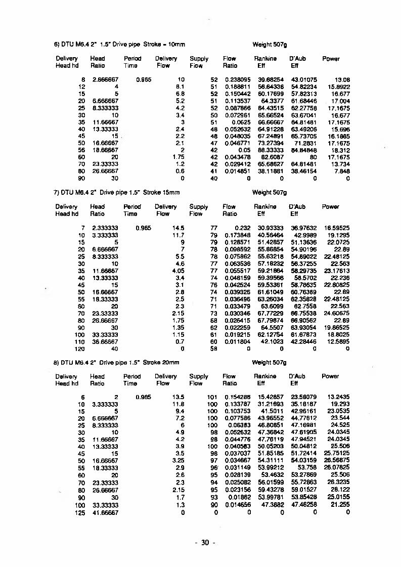
6) DTU M6.4 2" 1.5' Drive pipe Stroke - 10mm Weight 507g
Delivery Head Period Delivery Supply Flow Rankine D'Aub PowerHead hd Ratio Time Flow Flow Ratio Eff Eff
B 2.S66667 0.965 10 52 0.238095 39.68254 43.01075 13.0812 4 8.1 51 0.188811 56.64336 54.82234 15.892215 5 6.8 52 0.150442 60.17899 57.82313 16.67720 6.666667 5.2 51 0.113537 64.3377 61.68446 17.00425 8.333333 4.2 52 0.087866 64.43515 62.27758 17.167530 10 3.4 50 0.072961 65.66524 63.67041 16.67735 11.66667 3 51 0.0625 66.66667 64.81481 17.167540 13.33333 2.4 48 0.052632 64.91228 63.49206 15.69645 15 2.2 48 0.048035 67.24891 65.73705 16.186550 16.66667 2.1 47 0.046771 73.27394 71.2831 17.167556 18.66667 2 42 0.05 88.33333 84.84848 18.31260 20 1.75 42 0.043478 82.6087 80 17.167570 23.33333 1.2 42 0.029412 65.68627 64.81481 13.73480 26.66667 0.6 41 0.014851 38.11881 38.46154 7.84890 30 0 40 0 0 0 0
7) DTU M6.4 2" Drive pipe 1.5’ Stroke 15mm Weight 507g
Delivery Head Period Delivery Supply Flow Rankine D'Aub PowerHead hd Ratio TimB Flow Flow Ratio Eff Eff
7 2.333333 0.965 14.5 77 0.232 30.93333 36.97632 16.5952510 3.333333 11.7 79 0.173848 40.56464 42.9989 19.129515 5 9 79 0.128571 51.42857 51.13636 22.072520 6.666667 7 78 0.098592 55.86854 54.90196 22.8925 8.333333 5.5 78 0.075862 55.63218 54.89022 22.4812530 10 4.6 77 0.063536 57.18232 56.37255 22.56335 11.66667 4.05 77 0.065517 59.21864 58.29735 23.1761340 13.33333 3.4 74 0.048159 59.39566 58.5702 22.23645 15 3.1 76 0.042524 59.53361 58.78635 22.8082550 16.66667 2.8 74 0.039326 61.61049 60.76389 22.8955 18.33333 2.5 71 0.036496 63.26034 62.35828 22.4812580 20 2.3 71 0.033479 63.6099 62.7558 22.56370 23.33333 2.15 73 0.030346 67.77229 66.75538 24.6067580 26.66667 1.75 68 0.026415 67.79874 66.90562 22.8990 30 1.35 62 0.022259 64.5507 63.93054 19.86525
100 33.33333 1.15 61 0.019215 62.12754 61.67873 18.8025110 36 66667 0.7 60 0.011804 42.1023 42.28446 12.5895120 40 0 58 0 0 0 0
8) DTU M6.4 2" Drive pipe 1.5’ Stroke 20mm Weight 5Q7g
Delivery Head Period Delivery Supply Flow Rankine D’Aub PowerHead hd Ratio Time Flow Flow Ratio Eff Eff
6 2 0.965 13.5 101 0.154286 15.42857 23.58079 13.243510 3.333333 11.8 100 0.133787 31.21693 35.18187 19.29315 5 9.4 100 0.103753 41.5011 42.96161 23.053520 6.666667 7.2 100 0.077586 43.96552 44.77612 23.54425 8.333333 6 100 0.06383 46.80851 47.16981 24.52530 10 4.9 98 0.052632 47.36842 47.61905 24.034535 11.66667 4.2 98 0.044776 47.76119 47.94521 24.034540 13.33333 3.9 too 0.040583 50.05203 50.04812 25.50645 15 3.5 98 0.037037 51.85185 51.72414 25.7512550 16.66667 3.25 97 0.034667 54.31111 54.03159 26.5687555 18.33333 2.9 96' 0.031149 53.99212 53.758 26.0782560 20 2.6 95 0.028139 53.4632 53.27869 25.50670 23.33333 2.3 94 0.025082 56.01599 55.72863 26.323580 26.66667 2.15 95 0.023156 59.43278 59.01527 28.12290 30 1.7 93 0.01862 53.99781 53.85428 25.0155
100 33.33333 1.3 90 0.014656 47.3882 47.46258 21.255125 41.66667 0 0 0 0 0 0
- 30 -

9) DTU M6.4 2" Drive pipe 2" Stroke 20mm Weight 507g
Delivery Head Period Delivery Supply Flow Rankine D’Aub PowerHead hd Ratio Time Flow Flow Rato Eff Eff
7 2.333333 0.965 14 108 0.148936 19.85816 26 77596 16.02310 3.333333 13.3 108 0.140444 32.77015 36.5485 21.745515 5 11.3 106 0.119324 47.72967 48.16709 27.7132520 6.666667 8.7 105 0.090343 51.19418 51.01143 28.44925 8.333333 7.1 103 0.074035 54.29267 53.73903 29.0212530 10 5.8 100 0.061571 55.41401 54.82042 28.44935 11.66667 5.2 102 0.053719 57.30028 56.59204 29.75740 13.33333 4.4 100 0.046025 56.7643 56.19413 28.77645 15 3.9 98 0.041445 58.02338 57.40922 28.6942550 16.66667 3.5 97 0.037433 58.64528 58.04312 28.612555 18.33333 3.35 96 0.036158 62.67314 61.81849 30.1248860 20 3 96 0.032258 61.29032 60.60606 29.4370 23.33333 2.3 89 0.026528 59.24644 58.78058 26.323580 26.66667 2.1 85 0.025332 65.01809 64.29392 27.46890 30 1.6 86 0.018957 54.9763 54.79452 23.544
100 33.33333 1.3 86 0.015348 49.62613 49.63727 21.255110 36.66667 0.85 84 0.010222 36.46021 36.73149 15.28725130 43.33333 0 ERR ERR 0
10) DTU M6.4 2‘ Drive pipe 2" Stroke 15mm Weight 507g
Delivery Head Period Delivery Supply Flow Rankine D'Aub PowerHead hd Ratio Time Flow Flow Ratio Eff Eff
6 2 0.965 13.3 78 0.205564 20.55641 29.13472 13.047310 3.333333 11.6 78 0.174699 40.76305 43.15476 18.96615 5 9 79 0.12B571 51.42857 51.13636 22.072520 6.666667 7.1 77 0.101574 57.55842 56.2822 23.21725 8.333333 5.7 74 0.083455 61.20059 59.59849 23.2987530 10 4.8 76 0.067416 60.67416 59.40594 23.54435 11.66667 4 74 0.057143 60.95238 59.82906 22.8940 13.33333 3.7 73 0.053391 65.84897 64.31986 24.19845 15 3.2 74 0.045198 63.27684 62.17617 23.54450 16.66667 3 71 0.044118 69.11765 67.56757 24.52555 18.33333 2.6 68 0.039755 68.90928 67.51653 23.380560 20 2.3 65 0.036683 69.69697 68.35067 22.56370 23.33333 2.1 66 0.032864 73.39593 71.95301 24.034580 26.66667 1.65 68 0.024868 63.82818 63.17301 21.58290 30 1.42 71 0.020408 59.18367 58.82353 20.8953
100 33.33333 0.95 71 0.013562 43.84963 44.01205 15.5325120 40
11) DTU M6.4 2" Drive pipe 2" Stroke 10mm Weight - 507g
Delivery Head Period Delivery Supply Flow Rankine D’Aub PowerHead hd Ratio Time Flow Row Ratio Eff Eff
20 6.666667 0.965 4.8 48 0.111111 62.96296 66.66667 15.69625 8.333333 3.8 48 0.085973 63.04676 65.97222 15.532530 10 3.2 48 0.071429 64.28571 66.66667 15.69635 11.66667 2.7 49 0.058315 62.20302 64.28571 15.4507540 13.33333 2.35 45 0.0551 67.95623 69.62963 15.36945 15 2.15 42 0.053952 75.53325 76.78571 15.8186350 16.66667 2 43 0.04878 76.42276 77.51938 16.3560 20 1.85 45 0.042874 81.46002 82.22222 18.148570 23.33333 1.25 43 0.02994 66.86627 67.82946 14.3062580 26.66667 0.6 37 0.016484 42.30769 43.24324 7.84890 30 0 0 0 0 0 0
- 31 -
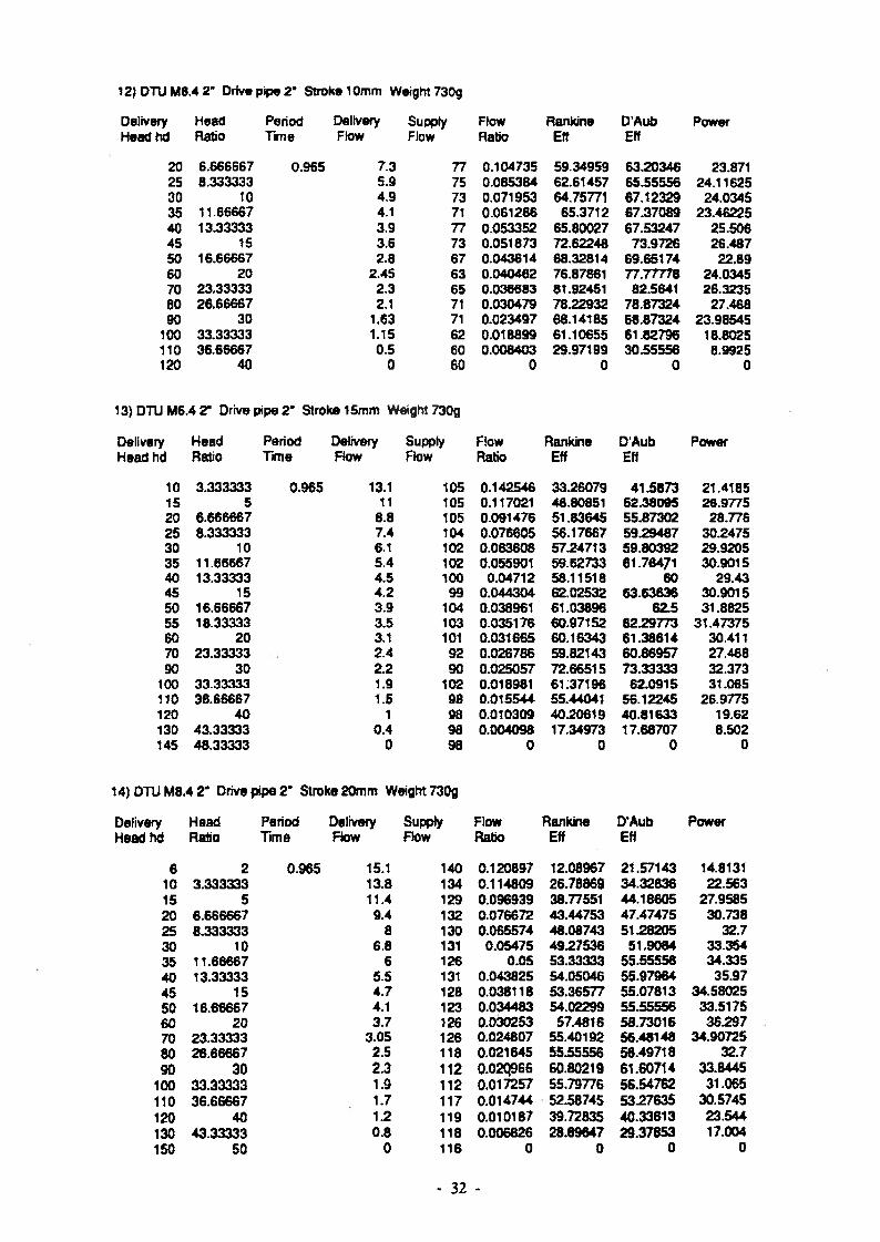
12) DTU M6.4 2’ Drive pip® 2" Stroks 10mm Weight 730g
Delivery Head Period Delivery Supply Flow Rankine D'Aub PowerHeadbd Ratio Time Flow Flow Ratio Eff Eff
20 6.666667 0.965 7.3 77 0.104735 59.34959 63.20346 23.87125 8.333333 5.9 75 0.0B5384 62.61457 65.55556 24.1162530 10 4.9 73 0.071953 64.75771 67.12329 24.034535 11.66667 4.1 71 0.061266 65.3712 67.37089 23.4622540 13.33333 3.9 77 0.053352 65.80027 67.53247 25.50645 15 3.6 73 0.051873 72.62248 73.9726 26.48750 16.66667 2.8 67 0.043614 68.32814 69.65174 22.8960 20 2.45 63 0.040462 76.87861 77.77778 24.034570 23.33333 2.3 65 0.036683 81.92451 82.5641 26.323580 26.66667 2.1 71 0.030479 78.22932 78.87324 27.46890 30 1.63 71 0.023497 68.14185 68.87324 23.98545
100 33.33333 1.15 62 0.018699 61.10655 61.82796 18.8025110 36.66667 0.5 60 0.008403 29.97199 30.55556 8.9925120 40 0 60 0 0 0 0
13) DTU M6.4 2’ Drive pipe 2 ’ Stroke 15mm Weight! 730g
Delivery Head Period Delivery Supply Flow Rankine D'Aub PowerHead hd Ratio Time Flow Flow Rato Eff Eff
10 3.333333 0.965 13.1 105 0.142546 33.26079 41.5873 21.418515 5 11 105 0.117021 48.80851 52.38095 26.977520 6.666667 8.8 105 0.091476 51.83645 55.87302 28.77625 8.333333 7.4 104 0.076605 56.17667 59.29487 30.247530 10 6.1 102 0.063608 57.24713 59.80392 29.920535 11.66667 5.4 102 0.055901 59.62733 61.76471 30.901540 13.33333 4.5 100 0.04712 58.11518 60 29.4345 15 4.2 99 0.044304 62.02532 63.63636 30.901550 16.66667 3.9 104 0.038961 61.03896 62.5 31.882555 18.33333 3.5 103 0.035176 60.97152 62.29773 31.4737560 20 3.1 101 0.031665 60.16343 61.38614 30.41170 23.33333 2.4 92 0.0267S6 59.82143 60.86957 27.46890 30 2.2 90 0.025057 72.66515 73.33333 32.373
100 33.33333 1.9 102 0.018981 6137196 62.0915 31.065110 36.66667 1.5 98 0.015544 55.44041 56.12245 26.9775120 40 1 98 0.010309 40.20619 40.81633 19.62130 43.33333 0.4 98 0.004098 17.34973 17.68707 8.502145 48.33333 0 98 0 0 0 0
14) DTU M8.4 2* Drive pipe 2" Stroke 20mm Weight 730g
Delivery HBad Period Delivery Supply Flow Rankine D'Aub PowerHeadM Ratio Time Flow Flow Ratio Eff Eff
6 2 0.965 15.1 140 0.120897 12.08967 21.57143 14.813110 3.333333 13.8 134 0.114809 26.78869 34.32836 22.56315 5 11.4 129 0.096939 38.77551 44.18605 27.958520 6.666667 9.4 132 0.076672 43.44753 47.47475 30.73825 6.333333 8 130 0.065574 48.08743 51.28205 32.730 10 6.8 131 0.05475 49.27536 51.9084 33.35435 11.66667 6 126 0.05 53.33333 55.55556 34.33540 13.33333 5.5 131 0.043825 54.05046 55.97964 35.9745 15 4.7 128 0.038118 53.36577 55.07813 34.5802550 16.66667 4.1 123 0.034483 54.02299 55.55556 33.517560 20 3.7 126 0.030253 57.4816 58.73016 36.29770 23.33333 3.05 126 0.024807 55.40192 56.48148 34.9072580 26.66667 2.5 118 0.021645 55.55556 56.49718 32.790 30 2.3 112 0.02Q966 60.80219 61.60714 33.8445
too 33.33333 1.9 112 0.017257 55.79776 56.54762 31.065110 36.66667 1.7 117 0.014744 52.58745 53.27635 30.5745120 40 1.2 119 0.010187 39.72835 40.33613 23.544130 43.33333 0.8 118 0.006826 28.69647 29.37653 17.004150 50 0 116 0 0 0 0
- 32 -

Appendix C FURTHER NOTES AND COMMENTS ON THE WORK AT DELFT
The following are a series of points arising from the work at Delft that have not been
mentioned in the main text of this paper.
1) Delft managed to record delivery valve movement of rubber type valves by bonding
strain guages to the rubber. This technique overcomes the difficulty of recording and
analysing delivery valve movement experienced by the DTU.
2) An electronic beat frequency counter was used at Delft to record the operating
frequency and period of pumps under test. This is another technique worth pursuing
for ongoing tests at Warwick.
3) There is some confusion and lack of consistancy between ram pump manufacturers and
users as to how efficiency is measured. Delft produce the following summary
Rankine Drive tank water level is taken as the datum point and supply and
delivery heads measured from that point. Therefore the net amount of potential energy in the water delivered = pgq(h->H)
the net amount of energy input = pgQH
Hence Rankine e f f i c i e n c y Hr = 9 * ft1'**)Q x H
D’Aubuisson The impulse valve orifice is taken as the datum point and therefore
work done = pgqh
energy supply = pg (Q + q)H
q x hD’Aubuisson E f f i c i e n c y tjd = — 3------------(Q + q) x H
Manufacturers
Most manufacturers take a simplified efficiency that actually produces a higher value of
efficiency under any given set of conditions
% = 'L^ h-Q x K
Delft prefer the Rankine expression which yields the lowest results particularly at low
- 33 -
delivery heads.
The DTU currently uses the D’Aubuisson formula as the test rig measures the total
flow into the pump (Q + q) rather than just the waste flow. This has been used
throughout this report.
There seems little to choose between these two which produce similar results under
normal operating conditions. The simplified efficiency used by many manufacturers is more inaccurate but produces more flattering figures!
4) Observation on relative position of delivery and impulse valves concerning air intake
during recoil.
During recoil, large quantities of air can be drawn in through
the open impulse valve as water flows back up the drive pipe.
Only a small quantity of air can be drawn through the snifter
valve so section A remains relatively full of water. As
acceleration of water towards the pump re-occurs the majority
of the air is expelled through the impulse valve and only the
small volume entering from the snifter enters the air vessel.
If the recoil is large in this configuration and a significant
quantity of air drawn in through the impulse valve, the
column may receed past the vertical pipe section leading to
the delivery valve. When acceleration occurs a significant
pocket of air may be trapped under the delivery valve. This
would tend to dampen out the next pressure pulse and reduce delivery flow.
5) The Alto ram from France has an inflatable rubber air compartment in the air vessel
to ensure a permanent separation of air and water. This is an attractive option as it
reduces the need for a reliable snifter to replenish air lost from the air vessel.
6) The SANO rams are fitted with a ‘drip valve’ in the air vessel that appears to be
located at a point where the air/water interface should be. It presumably operates by
passing water if the level in the air vessel rises above it. What is its operating mechanism?
8) Delft draw the following conclusions about pump performance and operation from
results produced by their mathematical model.
- 34 -
given an available source supply die pumping rate (q) is primarily determined by
the supply head (H,)and the delivery head (l\j).
an increase of the delivery head (fyj) decreases the quantity pumped per cycle
(V{j) and by that the pumping rate (q) decreases.
an increase of the supply head (Hg) increases the pumping frequency and by that the pumping rate (q) increases.
an increase of Uc (ie. the velocity of the water in the drive pipe at waste valve
closure) normally increases the pumping rate (q) while the pumping frequency
decreases, but more water (Q) is needed to operate the ram. However, there is
a limiation as to this point: an increase in such that the value of the ratio
Uc/Uo approaches unity (whgre Uq is the maximum attainable velocity of the
water in the drive pipe) implies a decrease in pumping rate (q) while, as before,
the waste flow (Q) increases, a condition to be avoided.
the larger the size (ie. drive pipe bore) of the ram, the more water (Q) is
required to operate the ram and the more water (q) can be delivered to a higher
level (hd).
9) Delft recommend that if the delivery flow from one ramains insufficient a second ram
should be placed below the first and utilise its drive water. However if there is
sufficient drive head available to be able to do this would a better performance be
gained by having two rams each working from a portion of the drive head or one ram
working with the total head available?
10) Delft stale that the drive pipe length should be approximately 4 to 7 times the supply
head. They make no justification for this statement.
11) Delft state that the best pumping results are usually obtained when the cut off velocity
is between 60% and 80% of the terminal velocity of the system.
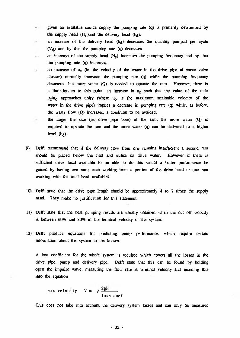
12) Delft produce equations for predicting pump performance, which require certain
information about the system to tbe known.
A loss coefficient for the whole system is required which covers all the losses in the
drive pipe, pump and delivery pipe. Delft state that this can be found by holding
open the impulse valve, measuring the flow rate at terminal velocity and inserting this
into the equation
max v e l o c i t y V = / -------l o s s coe f
This does not take into account the delivery system losses and can only be measured
- 35 -
once the system is installed, preventing prediction of performance prior to installation.
It would be more useful to have a loss coefficient measured for each pump and also
to have a simple method of calculating pipe loss coefficient based on diameter and length.
The other requirement for use of Delft’s model is to find the cut off velocity for the
particular impulse valve setting. They state that this can be found when the maximum
delivery head obtainable is known using
Cutoff = (g/c) x h ^
They recommend that Ifoax is found by closing the delivery side of the pump and
letting the pump run up to its maximum head. This would provide a rather crude
approximation producing a low result and could prove to be very dangerous.
- 36 -
Related Documents