International Research Journal of Engineering and Technology (IRJET) e-ISSN: 2395-0056 Volume: 02 Issue: 05 | Aug-2015 www.irjet.net p-ISSN: 2395-0072 © 2015, IRJET ISO 9001:2008 Certified Journal Page 1158 COMPARATIVE STUDY ON SEISMIC ANALYSIS OF MULTISTOREY BUILDING STIFFENED WITH BRACING AND SHEAR WALL. Mohd Atif 1 , Prof. Laxmikant Vairagade 2 , Vikrant Nair 3 1 P.G. Student, Civil Engineering Department, G.H.R.A.E.T Nagpur, Maharashtra, India 2 Assistant Professor, Civil Engineering Department, G.H.R.A.E.T, Nagpur, Maharashtra, India 3 Structural Consultant, Techpro Consultancy, Nagpur, Maharashtra, India ---------------------------------------------------------------------***--------------------------------------------------------------------- Abstract - This research work focuses on comparison of seismic analysis of G+15 building stiffened with bracings and shear wall. The performance of the building is analyzed in Zone II, Zone III, Zone IV, Zone V. The study includes understanding the main consideration factor that leads the structure to perform poorly during earthquake in order to achieve their appropriate behavior under future earthquakes. The analyzed structure is symmetrical, G+15, Ordinary RC moment-resting frame (OMRF). Modelling of the structure is done as per staad pro. V8i software. Time period of the structure in both the direction is retrieve from the software and as per IS 1893(part 1):2002 seismic analysis has undergone. The Lateral seismic forces of RC frame is carried out using linear static method as per IS 1893(part 1) : 2002 for different earthquake zones. The scope of present work is to understand that the structures need to have suitable Earthquake resisting features to safely resist large lateral forces that are imposed on them during Earthquake. Shear walls are efficient, both in terms of construction cost and effectiveness in minimizing Earthquake damage in structure. Also the braced frames can absorb great degree of energy exerted by earthquake.. The results of the performance and the analysis of the models are then graphically represented and also in tabular form and is compared for determining the best performance of building against lateral stiffness by arrangement of three different types of bracings with three different orientation of bracings and shear wall. A comparative analysis is done in terms of Base shear, Displacement, Axial load, Moments in Y and Z direction in columns and shear forces, maximum bending moments, max Torsion in beams. Key Words: Seismic analysis, Bracings, Shear Wall, Lateral Stiffness, Indian code IS 1893:2002 and OMRF. 1. INTRODUCTION 1.1 Overview The tallness of a building is relative and cannot be defined in absolute terms either in relation to height or the number of stories. But, from a structural engineer's point of view the tall building or multi-storied building can be defined as one that, by virtue of its height, is affected by lateral forces due to wind or earthquake or both to an extent that they play an important role in the structural design. Tall structures have fascinated mankind from the beginning of civilization. The Egyptian Pyramids, one among the seven wonders of world, constructed in 2600 B.C. are among such ancient tall structures. Such structures were constructed for defense and to show pride of the population in their civilization. The growth in modern multi-storied building construction, which began in late nineteenth century, is intended largely for commercial and residential purposes. The design of tall buildings essentially involves a conceptual design, approximate analysis, preliminary design and optimization, to safely carry gravity and lateral loads. The design criteria are, strength, serviceability, stability and human comfort. Earthquakes have become a frequent event all over the world. It is very difficult to predict the intensity, location, and time of occurrence of earthquake. Structures adequately designed for usual loads like dead, live, wind etc may not be necessarily safe against earthquake loading. It is neither practical nor economically viable to design structures to remain within elastic limit during earthquake. The design approach adopted in the Indian Code IS 1893(Part I): 2002 ‘Criteria for Earthquake Resistant Design Of Structures’ is to ensure that structures possess at least a minimum strength to withstand minor earthquake occurring frequently, without damage; resist moderate earthquakes without significant structural damage though some non-structural damage may occur; and aims that structures withstand major earthquake without collapse. Structures need to have suitable earthquake resistant features to safely resist large lateral forces that are imposed on them during frequent earthquakes. Ordinary structures for houses are usually built to safely carry their own weights. Low lateral loads caused by wind and therefore, perform poorly under large lateral forces caused by even moderate size earthquake. These lateral forces can produce the critical stresses in a structure, set up undesirable vibrations and, in addition, cause lateral sway of structure, which could reach a stage of discomfort to the occupants.

Welcome message from author
This document is posted to help you gain knowledge. Please leave a comment to let me know what you think about it! Share it to your friends and learn new things together.
Transcript

International Research Journal of Engineering and Technology (IRJET) e-ISSN: 2395-0056
Volume: 02 Issue: 05 | Aug-2015 www.irjet.net p-ISSN: 2395-0072
© 2015, IRJET ISO 9001:2008 Certified Journal Page 1158
COMPARATIVE STUDY ON SEISMIC ANALYSIS OF MULTISTOREY
BUILDING STIFFENED WITH BRACING AND SHEAR WALL.
Mohd Atif1, Prof. Laxmikant Vairagade2, Vikrant Nair3
1P.G. Student, Civil Engineering Department, G.H.R.A.E.T Nagpur, Maharashtra, India 2Assistant Professor, Civil Engineering Department, G.H.R.A.E.T, Nagpur, Maharashtra, India
3Structural Consultant, Techpro Consultancy, Nagpur, Maharashtra, India ---------------------------------------------------------------------***---------------------------------------------------------------------Abstract - This research work focuses on comparison of seismic analysis of G+15 building stiffened with bracings and shear wall. The performance of the building is analyzed in Zone II, Zone III, Zone IV, Zone V. The study includes understanding the main consideration factor that leads the structure to perform poorly during earthquake in order to achieve their appropriate behavior under future earthquakes. The analyzed structure is symmetrical, G+15, Ordinary RC moment-resting frame (OMRF). Modelling of the structure is done as per staad pro. V8i software. Time period of the structure in both the direction is retrieve from the software and as per IS 1893(part 1):2002 seismic analysis has undergone. The Lateral seismic forces of RC frame is carried out using linear static method as per IS 1893(part 1) : 2002 for different earthquake zones. The scope of present work is to understand that the structures need to have suitable Earthquake resisting features to safely resist large lateral forces that are imposed on them during Earthquake. Shear walls are efficient, both in terms of construction cost and effectiveness in minimizing Earthquake damage in structure. Also the braced frames can absorb great degree of energy exerted by earthquake.. The results of the performance and the analysis of the models are then graphically represented and also in tabular form and is compared for determining the best performance of building against lateral stiffness by arrangement of three different types of bracings with three different orientation of bracings and shear wall. A comparative analysis is done in terms of Base shear, Displacement, Axial load, Moments in Y and Z direction in columns and shear forces, maximum bending moments, max Torsion in beams.
Key Words: Seismic analysis, Bracings, Shear Wall, Lateral Stiffness, Indian code IS 1893:2002 and OMRF. 1. INTRODUCTION 1.1 Overview The tallness of a building is relative and cannot be defined in absolute terms either in relation to height or the number of stories. But, from a structural engineer's point of view the tall building or multi-storied building can be defined as one that, by virtue of its height, is affected by lateral forces due to wind or earthquake or both to an
extent that they play an important role in the structural design. Tall structures have fascinated mankind from the beginning of civilization. The Egyptian Pyramids, one among the seven wonders of world, constructed in 2600 B.C. are among such ancient tall structures. Such structures were constructed for defense and to show pride of the population in their civilization. The growth in modern multi-storied building construction, which began in late nineteenth century, is intended largely for commercial and residential purposes. The design of tall buildings essentially involves a conceptual design, approximate analysis, preliminary design and optimization, to safely carry gravity and lateral loads. The design criteria are, strength, serviceability, stability and human comfort. Earthquakes have become a frequent event all over the world. It is very difficult to predict the intensity, location, and time of occurrence of earthquake. Structures adequately designed for usual loads like dead, live, wind etc may not be necessarily safe against earthquake loading. It is neither practical nor economically viable to design structures to remain within elastic limit during earthquake. The design approach adopted in the Indian Code IS 1893(Part I): 2002 ‘Criteria for Earthquake Resistant Design Of Structures’ is to ensure that structures possess at least a minimum strength to withstand minor earthquake occurring frequently, without damage; resist moderate earthquakes without significant structural damage though some non-structural damage may occur; and aims that structures withstand major earthquake without collapse. Structures need to have suitable earthquake resistant features to safely resist large lateral forces that are imposed on them during frequent earthquakes. Ordinary structures for houses are usually built to safely carry their own weights. Low lateral loads caused by wind and therefore, perform poorly under large lateral forces caused by even moderate size earthquake. These lateral forces can produce the critical stresses in a structure, set up undesirable vibrations and, in addition, cause lateral sway of structure, which could reach a stage of discomfort to the occupants.

International Research Journal of Engineering and Technology (IRJET) e-ISSN: 2395-0056
Volume: 02 Issue: 05 | Aug-2015 www.irjet.net p-ISSN: 2395-0072
© 2015, IRJET ISO 9001:2008 Certified Journal Page 1159
Shear wall is one of the most commonly used lateral load resisting element in high rise building. Shear wall (SW) has high in plane stiffness and strength which can be used simultaneously to resist large horizontal load and support gravity load. The scope of present work is to study and investigate the effectiveness of RC shear wall in medium rise building. Reinforced concrete shear walls are used in Bare frame building to resist lateral force due to wind and earthquakes. They are usually provided between column lines, in stair wells, lift wells, in shafts. Shear wall provide lateral load resisting by transferring the wind or earthquake load to foundation. Besides, they impart lateral stiffness to the system and also carry gravity loads. But bare frame with shear wall still become economically unattractive. If the structural engineers consider property the non-structural element in structural design along with other elements like shear wall gives better results.
The most effective and practical method of enhancing the seismic resistance is to increase the energy absorption capacity of structures by combining bracing elements in the frame. The braced frame can absorb a greater degree of energy exerted by earthquakes. Bracing members are widely used in steel structures to reduce lateral displacement and dissipate energy during strong ground motions. This concept extended to concrete frames. The various aspects such as size and shape of building, location of shear wall and bracing in building, distribution of mass, distribution of stiffness greatly affect the behaviors of structures. Bracing system improves the seismic performance of the frame by increasing its lateral stiffness and capacity. To the addition of bracing system load could be transferred out of the frame and into the braces, by passing the weak columns. The stiffness added by the bracing system is maintained almost up to the peak strength. Stiffness is particularly important at serviceability state, where deformations are limited to prevent damage.
1.2 Objective of the Project Tall building developments have been rapidly increasing worldwide. The growth of multistory building in the last several decades is seen as the part of necessity for vertical expansion for business as well as residence in major cities. It is observed that there is a need to study the structural systems for R.C.C framed structure, which resists the lateral loads due to seismic effect. Safety and minimum damage level of a structure could be the prime requirement of tall buildings. To meet these requirements, the structure should have adequate lateral strength, lateral stiffness and sufficient ductility. Among the various structural systems, shear wall frame or braced concrete frame could be a point of choice for designer. Therefore, it attracts to review and observe the behavior of these structural systems under seismic effect. Hence, it is
proposed to study the dynamic behavior of reinforced concrete frame with and without shear wall and steel braced frame. The purpose of this study is to compare the seismic response of above structural systems. Axial forces and moments in members and floor displacements will be compared.
The most effective and practical method of enhancing the seismic resistance is to increase the energy absorption capacity of structures by combining bracing elements in the frame. The braced frame can absorb a greater degree of energy exerted by earthquakes. The present study is an effort towards analysis of the structure during the earthquake. G+15stories residential building is considered. To analyze a multi-storeyed RC framed building considering different earthquake intensities II, III, IV and V by response spectra method and find the base shear value for different structures. Seismic analysis of RC frame with bare and different position of shear wall and braced frame is carried out using Linear static analysis method as per IS 1893 (Part I): 2002[22] by using STAAD-PRO software .For this analysis different types of models are considered and comparison of seismic performance is carried out.
1.3 Methodology The methodology worked out to achieve the mentioned objectives is as follows:
1. Modeling of the selected building in Staad pro. V8i Software.
2. Retrieved time period of structure from the software.
3. Thirteen models as per the Indian code specification were prepared. Models including Bare frame, frames with shear walls and frames with bracings.
4. Applied calculated Lateral seismic forces and load combinations as per IS 1893-2002.
Analyzed the models for axial forces, moments, lateral displacements, max shear force and max torsion and graphical and tabular representation of the data is presented.
1.3.1 Time period
The Equivalent static methods works on seismic coefficient, which rely on the natural time period of vibration of the structure, the earthquake resistance design of the structures requires time period to calculate the base shear. The time period of the structure has been taken from the Staad pro software.

International Research Journal of Engineering and Technology (IRJET) e-ISSN: 2395-0056
Volume: 02 Issue: 05 | Aug-2015 www.irjet.net p-ISSN: 2395-0072
© 2015, IRJET ISO 9001:2008 Certified Journal Page 1160
Time period in X- direction = 1.02 Sa/g = 1.33 Time period in Y- direction= 1.44 Sa/g = 0.94
1.3.2 Load Combinations Load combinations that are to be used for Limit state Design of reinforced concrete structure are listed below. (1) 1.5(DL + LL) (2) 1.2(DL + LL ± EQ - X) (3) 1.2(DL + LL ± EQ - Y) (4) 1.5(DL ± EQ - X) (5) 1.5(DL ± EQ - Y) (6) 0.9DL ± 1.5EQ - X (7) 0.9DL ± 1.5EQ – Y
1.3.2 Distribution of the horizontal seismic
forces: Load and base shear calculation has been done as per IS 1893-2002. The base shear is calculated and distributed throughout the height at each floor of the building and the lateral seismic force induced at any level is determined.
Indian standards IS-1893:2002: IS 1893:2002 is denoted as “Criteria for earthquake resistant Design of structures” Part 1 General provisions and buildings. The design lateral force shall first be computed for the building as a whole. Thedesign lateral force shall then be distributed to the various floor levels. This overall design seismic force thus obtained at each floor level shall then be distributed to individual lateral load resisting elements depending on the floor diaphragm action. The design base shear calculated shall be distributed along the height of the building as per the following expression:
1.3.3 Mass and Base shear calculatons:
Mass calculations and base shear are summarized as:
ZONE
MODEL TYPE
TOTAL MASS KN
BASE SHEAR
in X- dir KN
BASE SHEAR in Z- dir KN
II
BF 51161.4 1136.64 804.94 DB1 51246.58 1138.53 806.28 DB2 51225.29 1138.06 805.94 DB3 51246.58 1138.53 806.28 VB1 51331.76 1140.42 807.62 VB2 51289.17 1139.47 806.95 VB3 51331.76 1140.42 807.62 XB1 51331.76 1140.42 807.62 XB2 51289.17 1139.47 806.95 XB3 51331.76 1140.42 807.62 SW1 37518 833.52 587.78 SW2 36557.55 812.19 572.73 SW3 46864.05 1041.16 737.33
III
BF 51161.4 1818.62 1287.9 DB1 51246.58 1821.65 1290.05 DB2 51225.29 1820.89 1289.51 DB3 51246.58 1821.65 1290.05 VB1 51331.76 1824.67 1292.19 VB2 51289.17 1823.16 1291.12 VB3 51331.76 1824.67 1292.19 XB1 51331.76 1824.67 1292.19 XB2 51289.17 1823.16 1291.12 XB3 51331.76 1824.67 1292.19 SW1 37518 1333.64 940.45 SW2 36557.55 1299.5 916.38 SW3 46864.05 1665.86 1179.72
IV
BF 51161.4 2727.93 1931.85 DB1 51246.58 2732.47 1935.07 DB2 51225.29 2731.33 1934.27 DB3 51246.58 2732.47 1935.07 VB1 51331.76 2737.01 1938.29 VB2 51289.17 2734.74 1936.68 VB3 51331.76 2737.01 1938.29 XB1 51331.76 2737.01 1938.29 XB2 51289.17 2734.74 1936.68 XB3 51331.76 2737.01 1938.29 SW1 37518 2000.46 1410.68 SW2 36557.55 1949.25 1374.56 SW3 46864.05 2498.79 1769.59

International Research Journal of Engineering and Technology (IRJET) e-ISSN: 2395-0056
Volume: 02 Issue: 05 | Aug-2015 www.irjet.net p-ISSN: 2395-0072
© 2015, IRJET ISO 9001:2008 Certified Journal Page 1161
1.3.3 Specifications The specifications used in modeling are
Sr. No
Parameters Dimensions/Type
1 Plan dimension 18m x 9 m
2 Number of stories G+15
3 Total height of building 48m 4 Height of each storey 3m 5 Column size 230 X 600 mm 6 Beam size 230 x 400 mm 7 Grade of concrete M20 8 Frame type OMRF 9 Soil type Medium soil
10 Live load 3 KN/sq.m 11 Floor finish 1 KN/sq.m 12 Inner wall 230 mm 13 Outer wall 230 mm 14 Slab thickness 230mm 15 Unit weights of Concrete 25 KN/Cum
16 Unit weights of brick work
19 KN/Cum
17 Shear wall thickness 200mm 18 Section for steel bracing ISA 110 X 110 X 10mm
1.3.4 Modeling: This building has been modeled as 3D Space frame model with six degree of freedom at each node using STAAD - PRO, software for stimulation of behavior under gravity
and seismic loading. The isometric 3D view and plan of the building model is shown as figure. The support condition is considered as fully fixed.
Fig-1: Plan of the selected building
Fig-2: 3D View of the selected building
ZONE
MODEL TYPE
TOTAL MASS KN
BASE SHEAR
in X- dir KN
BASE SHEAR in Z- dir KN
V
BF 51161.4 4091.89 2897.78 DB1 51246.58 4098.7 2902.61 DB2 51225.29 4097 2901.4 DB3 51246.58 4098.7 2902.61 VB1 51331.76 4105.51 2907.43 VB2 51289.17 4102.11 2905.02 VB3 51331.76 4105.51 2907.43 XB1 51331.76 4105.51 2907.43 XB2 51289.17 4102.11 2905.02 XB3 51331.76 4105.51 2907.43 SW1 37518 3000.69 2116.02 SW2 36557.55 2923.87 2061.85 SW3 46864.05 3748.19 2654.38

International Research Journal of Engineering and Technology (IRJET) e-ISSN: 2395-0056
Volume: 02 Issue: 05 | Aug-2015 www.irjet.net p-ISSN: 2395-0072
© 2015, IRJET ISO 9001:2008 Certified Journal Page 1162
Fig-3: Building with diagonal bracings at corner (DB1) Fig-4: Building with diagonal bracings at periphery (DB2)
Fig-5: Building with diagonal bracings at outer and inner position (DB3)
Fig-6: Building with V- bracings at corner (VB1)
Fig-7: Building with V- bracings at periphery (VB2)

International Research Journal of Engineering and Technology (IRJET) e-ISSN: 2395-0056
Volume: 02 Issue: 05 | Aug-2015 www.irjet.net p-ISSN: 2395-0072
© 2015, IRJET ISO 9001:2008 Certified Journal Page 1163
Fig-8: Building with V- bracings at outer and inner position (VB3)
Fig-9: Building with X- bracings at corner (XB1)
Fig-10: Building with X- bracings at periphery (XB2)
Fig11: Building with X- bracings at outer and inner position(XB3)
Fig-12: Building with Shear walls at corner (SW1)

International Research Journal of Engineering and Technology (IRJET) e-ISSN: 2395-0056
Volume: 02 Issue: 05 | Aug-2015 www.irjet.net p-ISSN: 2395-0072
© 2015, IRJET ISO 9001:2008 Certified Journal Page 1164
Fig-13: Building with Shear Walls at periphery (SW2)
Fig13: Building with Shear walls at outer and inner pos. (SW3)
2 ANALYSIS AND RESULTS 2.1 OVERVIEW A G+15 building is analyzed and compared with shear wall and three different patterns of bracings with three different positioning of it during the earthquake considering all the four zones. Parameters like displacement, axial force, bending moment for columns and shear, moment, torsion for beams are calculated. Graphical and Tabular representation of data is discussed in this chapter.
2.2 Column
2.2.1 Maximum Displacements
Table-1: Maximum lateral displacement
Fig-2.2.1: Comparison of Maximum lateral displacement.
ZONE SOIL TYPE TYPE MAX DEFL. mm
IV MEDIUM
BF 341.641
DB1 222.012
DB2 247.796
DB3 282.161
VB1 207.066
VB2 236.085
VB3 256.524
XB1 195.09
XB2 225.44
XB3 241.876
SW1 118.825
SW2 219.33 SW3 112.107
ZONE SOIL TYPE TYPE MAX DEFL. mm
II MEDIUM
BF 143.817
DB1 98.138
DB2 108.318
DB3 123.313
VB1 88.8
VB2 99.947
VB3 111.55
XB1 83.841
XB2 96.093
XB3 105.852
SW1 52.917
SW2 92.278
SW3 49.041
ZONE SOIL TYPE TYPE MAX DEFL. mm
III MEDIUM
BF 228.391
DB1 150.545
DB2 167.972
DB3 191.079
VB1 138.947
VB2 158.558
VB3 173.403
XB1 130.711
XB2 151.497
XB3 163.853
SW1 80.695
SW2 146.63 SW3 75.721
ZONE SOIL TYPE TYPE MAX DEFL. mm
V MEDIUM
BF 511.748
DB1 329.173
DB2 369.401
DB3 419.241
VB1 309.157
VB2 353.908
VB3 381.551
XB1 290.725
XB2 337.882
XB3 359.278
SW1 329.173
SW2 369.401 SW3 219.241

International Research Journal of Engineering and Technology (IRJET) e-ISSN: 2395-0056
Volume: 02 Issue: 05 | Aug-2015 www.irjet.net p-ISSN: 2395-0072
© 2015, IRJET ISO 9001:2008 Certified Journal Page 1165
2.2.2 Maximum Axial Force on columns
Table-2: Maximum Axial Force
Fig-2.2.2: Comparison of Maximum Axial force
ZONE SOIL TYPE TYPE MAX. AXIAL FORCE KN
II MEDIUM
BF 3754.125
DB1 3676.076
DB2 3633.57
DB3 4365.885
VB1 3662.431
VB2 3600.98
VB3 4205.122
XB1 3660.097
XB2 3616.189
XB3 4368.47
SW1 3446.125
SW2 3009.234
SW3 2703.727
ZONE SOIL TYPE TYPE MAX. AXIAL FORCE KN
III MEDIUM
BF 3754.125
DB1 3676.076
DB2 3779.796
DB3 5143.843
VB1 3662.431
VB2 3732.18
VB3 4947.643
XB1 3660.097
XB2 3965.621
XB3 5141.555
SW1 3446.125
SW2 3009.234
SW3 2703.727
ZONE SOIL TYPE TYPE MAX. AXIAL FORCE KN
IV MEDIUM
BF 4080.79
DB1 4470.95
DB2 4483.657
DB3 6188.884
VB1 4130.686
VB2 4465.085
VB3 5976.484
XB1 4320.864
XB2 4787.607
XB3 6211.149
SW1 3453.888
SW2 3016.997
SW3 2830.39
ZONE SOIL TYPE TYPE MAX. AXIAL FORCE KN
V MEDIUM
BF 4806.754
DB1 5684.934
DB2 5532.102
DB3 7744.801
VB1 5300.399
VB2 5561.863
VB3 7461.526
XB1 5530.95
XB2 6019.381
XB3 7757.32
SW1 5684.934
SW2 5532.102
SW3 4744.801

International Research Journal of Engineering and Technology (IRJET) e-ISSN: 2395-0056
Volume: 02 Issue: 05 | Aug-2015 www.irjet.net p-ISSN: 2395-0072
© 2015, IRJET ISO 9001:2008 Certified Journal Page 1166
2.2.3 Maximum Moment in columns Table-3: Maximum Moment in columns
ZONE SOIL TYPE TYPE MAX.MOMENT KN-m
II MEDIUM
BF 126.818
DB1 129.019
DB2 166.199
DB3 123.71
VB1 108.32
VB2 98.933
VB3 108.921
XB1 104.818
XB2 106.402
XB3 112.518
SW1 153.471
SW2 78.053
SW3 125.172
ZONE SOIL TYPE TYPE MAX.MOMENT KN-m
III MEDIUM
BF 200.963
DB1 197.255
DB2 261.507
DB3 200.578
VB1 154.956
VB2 142.515
VB3 150.414
XB1 155.434
XB2 161.543
XB3 166.58
SW1 183.425
SW2 100.503
SW3 143.837
ZONE SOIL TYPE TYPE MAX.MOMENT KN-m
IV MEDIUM
BF 301.426
DB1 288.603
DB2 388.063
DB3 303.525
VB1 223.593
VB2 205.561
VB3 209.105
XB1 222.093
XB2 233.728
XB3 238.316
SW1 223.069
SW2 133.891
SW3 178.032
ZONE SOIL TYPE TYPE MAX.MOMENT KN-m
V MEDIUM
BF 451.383
DB1 425.079
DB2 567.75
DB3 472.812
VB1 326.99
VB2 307.431
VB3 310.17
XB1 324.714
XB2 342.01
XB3 346.378
SW1 425.079
SW2 367.75
SW3 412.812
International Research Journal of Engineering and Technology (IRJET) e-ISSN: 2395-0056
Volume: 02 Issue: 05 | Aug-2015 www.irjet.net p-ISSN: 2395-0072
© 2015, IRJET ISO 9001:2008 Certified Journal Page 1167
Fig-2.2.3: Comparison of Maximum moments(KN-M)
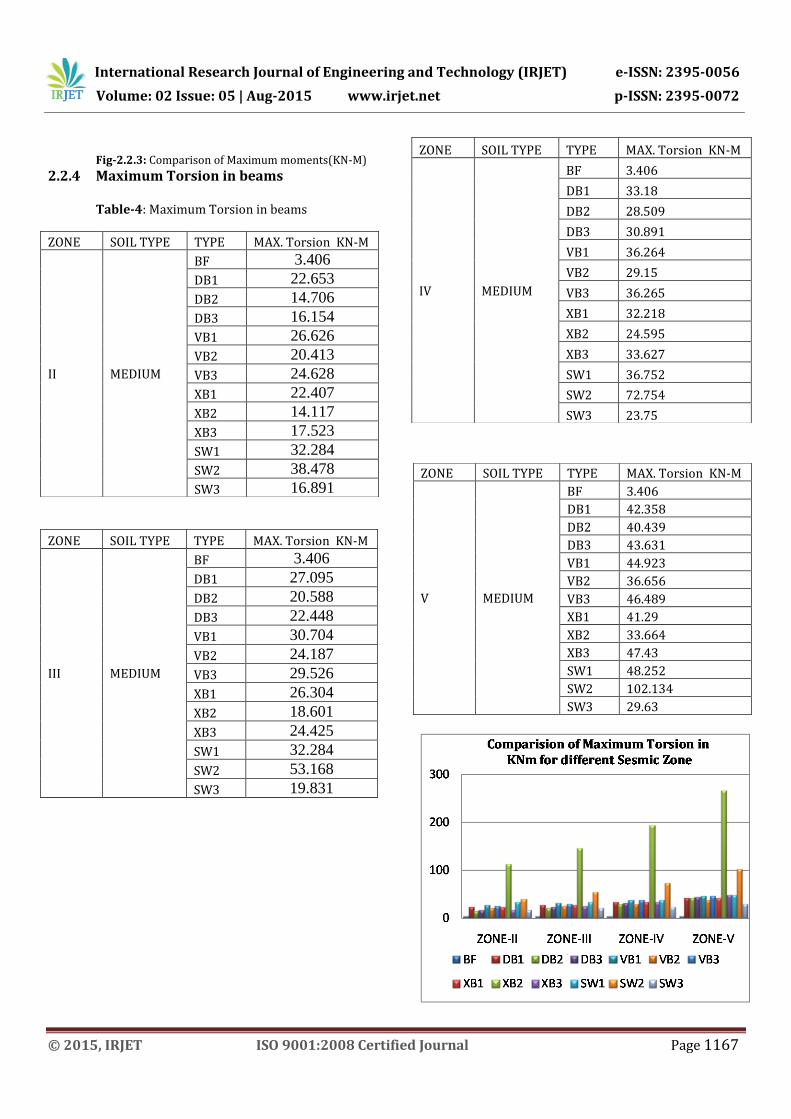
2.2.4 Maximum Torsion in beams Table-4: Maximum Torsion in beams
ZONE SOIL TYPE TYPE MAX. Torsion KN-M
II MEDIUM
BF 3.406
DB1 22.653
DB2 14.706
DB3 16.154
VB1 26.626
VB2 20.413
VB3 24.628
XB1 22.407
XB2 14.117
XB3 17.523
SW1 32.284
SW2 38.478
SW3 16.891
ZONE SOIL TYPE TYPE MAX. Torsion KN-M
III MEDIUM
BF 3.406
DB1 27.095
DB2 20.588
DB3 22.448
VB1 30.704
VB2 24.187
VB3 29.526
XB1 26.304
XB2 18.601
XB3 24.425
SW1 32.284
SW2 53.168
SW3 19.831
ZONE SOIL TYPE TYPE MAX. Torsion KN-M
IV MEDIUM
BF 3.406
DB1 33.18
DB2 28.509
DB3 30.891
VB1 36.264
VB2 29.15
VB3 36.265
XB1 32.218
XB2 24.595
XB3 33.627
SW1 36.752
SW2 72.754
SW3 23.75
ZONE SOIL TYPE TYPE MAX. Torsion KN-M
V MEDIUM
BF 3.406
DB1 42.358
DB2 40.439
DB3 43.631
VB1 44.923
VB2 36.656
VB3 46.489
XB1 41.29
XB2 33.664
XB3 47.43
SW1 48.252
SW2 102.134
SW3 29.63

International Research Journal of Engineering and Technology (IRJET) e-ISSN: 2395-0056
Volume: 02 Issue: 05 | Aug-2015 www.irjet.net p-ISSN: 2395-0072
© 2015, IRJET ISO 9001:2008 Certified Journal Page 1168
Fig-2.2.4: Comparison of Maximum Torsion in KN-M
2.2.5 Maximum Shear Force in beams Table5: Maximum Shear Force in beams
Fig-2.2.5: Comparison of Maximum Shear Force in KN
ZONE SOIL TYPE TYPE MAX. Shear Force KN
IV MEDIUM
BF 218.074
DB1 225.548
DB2 244.451
DB3 226.616
VB1 208.606
VB2 199.395
VB3 222.312
XB1 212.821
XB2 192.901
XB3 230.083
SW1 232.594
SW2 217.858
SW3 226.96
ZONE SOIL TYPE TYPE MAX. Shear Force KN
II MEDIUM
BF 124.754
DB1 131.386
DB2 129.777
DB3 127.152
VB1 123.726
VB2 138.309
VB3 161.741
XB1 126.963
XB2 111.387
XB3 127.548
SW1 154.856
SW2 161.105
SW3 161.183
ZONE SOIL TYPE TYPE MAX. Shear Force KN
III MEDIUM
BF 162.906
DB1 171.271
DB2 178.986
DB3 168.9
VB1 159.966
VB2 164.224
VB3 187.604
XB1 163.927
XB2 145.142
XB3 170.622
SW1 174.066
SW2 184.836
SW3 177.274
ZONE SOIL TYPE TYPE MAX. Shear Force KN
V MEDIUM
BF 301.32
DB1 306.635
DB2 343.052
DB3 313.19
VB1 282.809
VB2 263.032
VB3 307.138
XB1 287.62
XB2 264.539
XB3 319.274
SW1 327.298
SW2 268.88
SW3 315.367

International Research Journal of Engineering and Technology (IRJET) e-ISSN: 2395-0056
Volume: 02 Issue: 05 | Aug-2015 www.irjet.net p-ISSN: 2395-0072
© 2015, IRJET ISO 9001:2008 Certified Journal Page 1169
2.2.6 Maximum Banding Moments in beams Table-6: Maximum Bending Moments in beams
Fig-2.2.6: Comparison of Max Bending Moment in KNM
ZONE SOIL TYPE TYPE MAX.Bending Moment (KN-M)
IV MEDIUM
BF 279.626
DB1 299.361
DB2 325.499
DB3 285.92
VB1 272.145
VB2 244.727
VB3 269.389
XB1 280.431
XB2 248.03
XB3 291.714
SW1 307.192
SW2 326.849
SW3 289.273
ZONE SOIL TYPE TYPE MAX.Bending Moment (KN-M)
II MEDIUM
BF 140.675
DB1 156.132
DB2 148.978
DB3 139.584
VB1 143.332
VB2 124.651
VB3 136.62
XB1 149.443
XB2 120.803
XB3 140.255
SW1 184.371
SW2 219.48
SW3 195.675
ZONE SOIL TYPE TYPE MAX.Bending Moment (KN-M)
III MEDIUM
BF 199.346
DB1 216.778
DB2 226.704
DB3 199.148
VB1 198.372
VB2 171.62
VB3 184.174
XB1 205.821
XB2 175.778
XB3 202.523
SW1 218.915
SW2 264.667
SW3 220.104
ZONE SOIL TYPE TYPE MAX.Bending Moment (KN-M)
V MEDIUM
BF 403.62
DB1 422.737
DB2 474.302
DB3 416.078
VB1 384.955
VB2 352.464
VB3 397.211
XB1 394.331
XB2 356.408
XB3 425.501
SW1 449.248
SW2 423.028
SW3 421.859

International Research Journal of Engineering and Technology (IRJET) e-ISSN: 2395-0056
Volume: 02 Issue: 05 | Aug-2015 www.irjet.net p-ISSN: 2395-0072
© 2015, IRJET ISO 9001:2008 Certified Journal Page 1170
CONCLUSIONS
1. Shear wall elements are very much efficient in reducing lateral displacement of frame as drift and horizontal deflection induced in shear wall frame are much less than that induced in braced frame and plane frame.
2. The location of shear-wall and brace member has significant effect on the seismic response than the plane frame.
3. The location of shear-wall- 3 is favorable as they are effective in reducing actions induced in frame with less horizontal deflection and drift.
% REDUCTION OF MAXIMUML LATERAL DSLACEMENT in mm
ZONE BF SW3 % Reduction
ZONE-II 143.817 49.041 65.90% ZONE-
III 228.391 75.721 66.85% ZONE-
IV 341.641 112.107 67.19%
ZONE-V 511.748 219.241 57.16%
4. Shear wall construction will provide large
stiffness to the building by reducing the damage to the structure.
5. The concept of using steel bracing is one of the advantageous concepts which can be used to strengthen or retrofit the existing structures.
6. Steel bracings can be used as an alternative to the other strengthening or retrofitting techniques available as the total weight on the existing building will not change significantly.
7. Steel bracings reduce flexure and shear demands on beams and columns and transfer the lateral loads through axial load mechanism.
8. The lateral displacements of the building studied are reduced by the use of X type of bracing systems.
9. The building frames with X bracing system will have minimum possible bending moments in comparison to other types of bracing systems.
10. Using steel bracings the total weight on the existing building will not change significantly.
11. The lateral displacement of the building is reduced by 35% to 45 % by the use of X Type steel bracing system, and X bracing type reduced maximum displacement.
REFERENCES
[1] Himalee Rahangadle, S. R. Satone, “Design and Analysis of Multistoried Building with Effect of Shear wall”, International journal of Engineering Reserch and Applications, Vol 3, Issue 3, pp-223-232, ISSN:2248-9622.
[2] Arlekar J. N., Jain S. K. and Murty C. V.R., “Seismic Response of RC Frame Building with Soft First Storey”, proceeding of CBRI Golden Jubliee Conference on Natural Hazards in Urban Habitat, 1997, New Delhi, pp.13-24.
[3] Anand. N., Mightraj. C., Prince Arulraj G., “Seismic Behaviour of RCC shear wall Under Different Soil Conditions”, Indian Geotechnical Conference-2012, GEO trendz , IGS Mumbai chapter ant IIT Bombay.
[4] FEMA 356, Presented and Commentry for the Seismic Rehabilitation of Buildings, Federal Emergency Management Agency , Washington, 2000.
[5] Nabin Raj C. , S. Elavenil, “ Analytical Study on Seismic Performance of Hybrid (Dual) Structural System Subjected to Earthquake”, International Journal of Modern Engineering Research. Vol.2, Issue.4, 2012, pp2358-2363, ISSN:2249-6645.
[6] Kumar, S. R. and kumar, G. R., “Seismic Retrofit of Soft Storey Building using Steel Bracing”, Workshop on retrofitting of structures, Oct 10-11, 2003, IIT Roorkee,pp. 148-158.
[7] Lawson R.S.. Vicki Vance, Krawinkler H., “Nonlinear Static Pushover Analysis- Why, When, and How?”, Fifth US National Conference on Earthquake Engineering Proceeding, Vol.1, 1994, pp.283-292.
[8] Krawinkler H., Seneviratna G., “Pros and Cones of Pushover analysis of seismic performance Evaluation”, Engineering Structures, Vol.20, No.4-6,1997.
[9] M.D. Kevadkar, P. B. Kodag, “Lateral Load analysis of R.C.C Building”, International Journal of Modern Engineering Research Vol.3, Issue3,2013. Pp1428-
1434, ISSN:2249-6645. [10] Kadid A. and Boumrkik A., “Pushover Analysis of
Reinforced Concrete Frames Structures”, Asian Journal of Civil Engineering (Building and Housing), VOL.9, No.1, 2008,pp.75-83.
[11] Kabeyasawa, T., Sanada, Y. and Kuramoto, H., “Design and Analysis of a Six Storey RC Frame- wall System with Soft First Storey for Shaking Table Test”, Vol.35, NO.11, 2006, PP.1425-1451.
[12] Sundar M. Deshmukh, J. G. Kulkarni, “ Analysis of Partially Braced Multistorey Building Frames Subjected to Gravity and Earthquake Loads”, International Journal of Advance Research In Science and Engineering. Vol. No.2, Issue No.8, 2013, ISSN 2319-8354.
Related Documents