INTERNATIONAL JOURNAL OF RESEARCH IN AERONAUTICAL AND MECHANICAL ENGINEERING WWW.IJRAME.COM ISSN (ONLINE): 2321-3051 Emerging Trends in Mechanical Engineering Proceedings of the International Conference, ETME-2017, 27 & 28 December, 2017, Pg: -535-552 Suvechha Hota - 535 - COMPARATIVE STUDY OF REVERSE CYCLE DEFROSTING AND ELECTRIC DEFROSTING FOR REFRIGERATOR Suvechha Hota 1 , Prasanta Kumar Satapathy 2 1 Research Scholar , Department of Mechanical Engineering, College of Engineering and Technology, Bhubaneswar, E-mail id- [email protected], Mobile no.-+91- 9776362272. 2 Associate Professor , Department of Mechanical Engineering, College of Engineering and Technology , Bhubaneswar. *Author for correspondence ABSTRACT As the excessive frost deposition on the surface of the evaporator coil results in poor refrigerating effect and the frost layer acts as an insulator resulting reduction in heat transfer rate. Hence an efficient defrosting method plays an important role for a refrigeration cycle. This paper presents the different parameters involved in frosting and defrosting by considering a 225 litre refrigerator running with refrigerant R-134a. The parameter like overall heat transfer co-efficient is calculated during frosting. Analytical study has been carried out to calculate the frost thickness by considering different relative humidity, operation time which is given by the modified Ivanova‟s model. And during defrosting the melting time required for particular frost thickness are calculated for different power inputs by reverse cycle defrosting method and electric defrosting method. The effects on heat transfer and frost thickness during frosting under different temperatures of refrigerant and different atmospheric temperatures have been studied. KEY WORDS: Frosting, Overall Heat Transfer Co-efficient, Reverse Cycle Defrosting, Electric Defrosting INTRODUCTION Out of all these refrigeration systems, based on commercial and domestic purposes, the vapour compression refrigeration system is most, useful and economic system. The V-C cycle (as shown in figure 1), uses a liquid refrigerant as a medium which absorbs heat from the refrigerated space and rejects it in the condenser to maintain the lower temperature [12][8].

Welcome message from author
This document is posted to help you gain knowledge. Please leave a comment to let me know what you think about it! Share it to your friends and learn new things together.
Transcript
INTERNATIONAL JOURNAL OF RESEARCH IN AERONAUTICAL AND MECHANICAL ENGINEERING
WWW.IJRAME.COM ISSN (ONLINE): 2321-3051
Emerging Trends in Mechanical Engineering Proceedings of the
International Conference, ETME-2017, 27 & 28 December, 2017, Pg: -535-552
Suvechha Hota
- 535 -
COMPARATIVE STUDY OF REVERSE CYCLE
DEFROSTING AND ELECTRIC DEFROSTING FOR
REFRIGERATOR
Suvechha Hota1, Prasanta Kumar Satapathy
2
1 Research Scholar , Department of Mechanical Engineering, College of Engineering and
Technology, Bhubaneswar, E-mail id- [email protected], Mobile no.-+91-
9776362272. 2 Associate Professor , Department of Mechanical Engineering, College of Engineering and
Technology , Bhubaneswar.
*Author for correspondence
ABSTRACT
As the excessive frost deposition on the surface of the evaporator coil results in poor refrigerating effect and the frost layer acts as an insulator resulting reduction in heat transfer rate. Hence an efficient defrosting
method plays an important role for a refrigeration cycle. This paper presents the different parameters involved in frosting and defrosting by considering a 225 litre refrigerator running with refrigerant R-134a. The parameter like overall heat transfer co-efficient is calculated during frosting. Analytical study has been carried out to calculate the frost thickness by considering different relative humidity, operation time which is given by the modified Ivanova‟s model. And during defrosting the melting time required for particular frost thickness are calculated for different power inputs by reverse cycle defrosting method and electric defrosting method. The effects on heat transfer and frost thickness during frosting under different temperatures of refrigerant and different atmospheric temperatures have been studied.
KEY WORDS: Frosting, Overall Heat Transfer Co-efficient, Reverse Cycle Defrosting,
Electric Defrosting
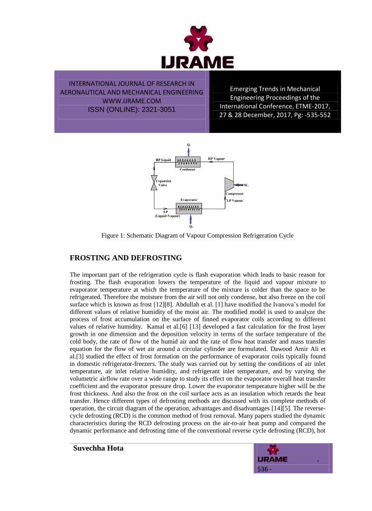
INTRODUCTION Out of all these refrigeration systems, based on commercial and domestic purposes, the vapour
compression refrigeration system is most, useful and economic system. The V-C cycle (as shown
in figure 1), uses a liquid refrigerant as a medium which absorbs heat from the refrigerated space
and rejects it in the condenser to maintain the lower temperature [12][8].
INTERNATIONAL JOURNAL OF RESEARCH IN AERONAUTICAL AND MECHANICAL ENGINEERING
WWW.IJRAME.COM ISSN (ONLINE): 2321-3051
Emerging Trends in Mechanical Engineering Proceedings of the
International Conference, ETME-2017, 27 & 28 December, 2017, Pg: -535-552
Suvechha Hota
- 536 -
Figure 1: Schematic Diagram of Vapour Compression Refrigeration Cycle
FROSTING AND DEFROSTING
The important part of the refrigeration cycle is flash evaporation which leads to basic reason for
frosting. The flash evaporation lowers the temperature of the liquid and vapour mixture to
evaporator temperature at which the temperature of the mixture is colder than the space to be
refrigerated. Therefore the moisture from the air will not only condense, but also freeze on the coil
surface which is known as frost [12][8]. Abdullah et al. [1] have modified the Ivanova‟s model for
different values of relative humidity of the moist air. The modified model is used to analyze the process of frost accumulation on the surface of finned evaporator coils according to different
values of relative humidity. Kamal et al.[6] [13] developed a fast calculation for the frost layer
growth in one dimension and the deposition velocity in terms of the surface temperature of the
cold body, the rate of flow of the humid air and the rate of flow heat transfer and mass transfer
equation for the flow of wet air around a circular cylinder are formulated. Dawood Amir Ali et
al.[3] studied the effect of frost formation on the performance of evaporator coils typically found
in domestic refrigerator-freezers. The study was carried out by setting the conditions of air inlet
temperature, air inlet relative humidity, and refrigerant inlet temperature, and by varying the
volumetric airflow rate over a wide range to study its effect on the evaporator overall heat transfer
coefficient and the evaporator pressure drop. Lower the evaporator temperature higher will be the
frost thickness. And also the frost on the coil surface acts as an insulation which retards the heat transfer. Hence different types of defrosting methods are discussed with its complete methods of
operation, the circuit diagram of the operation, advantages and disadvantages [14][5]. The reverse-
cycle defrosting (RCD) is the common method of frost removal. Many papers studied the dynamic
characteristics during the RCD defrosting process on the air-to-air heat pump and compared the
dynamic performance and defrosting time of the conventional reverse cycle defrosting (RCD), hot
INTERNATIONAL JOURNAL OF RESEARCH IN AERONAUTICAL AND MECHANICAL ENGINEERING
WWW.IJRAME.COM ISSN (ONLINE): 2321-3051
Emerging Trends in Mechanical Engineering Proceedings of the
International Conference, ETME-2017, 27 & 28 December, 2017, Pg: -535-552
Suvechha Hota
- 537 -
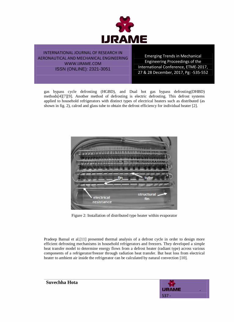
gas bypass cycle defrosting (HGBD), and Dual hot gas bypass defrosting(DHBD)
methods[4][7][9]. Another method of defrosting is electric defrosting. This defrost systems
applied to household refrigerators with distinct types of electrical heaters such as distributed (as
shown in fig. 2), calrod and glass tube to obtain the defrost efficiency for individual heater [2].
Figure 2: Installation of distributed type heater within evaporator
Pradeep Bansal et al.[11] presented thermal analysis of a defrost cycle in order to design more efficient defrosting mechanisms in household refrigerators and freezers. They developed a simple
heat transfer model to determine energy flows from a defrost heater (radiant type) across various
components of a refrigerator/freezer through radiation heat transfer. But heat loss from electrical
heater to ambient air inside the refrigerator can be calculated by natural convection [10].
INTERNATIONAL JOURNAL OF RESEARCH IN AERONAUTICAL AND MECHANICAL ENGINEERING
WWW.IJRAME.COM ISSN (ONLINE): 2321-3051
Emerging Trends in Mechanical Engineering Proceedings of the
International Conference, ETME-2017, 27 & 28 December, 2017, Pg: -535-552
Suvechha Hota
- 538 -
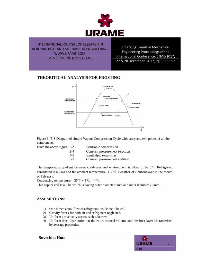
THEORITICAL ANALYSIS FOR FROSTING
Figure 3: T-S Diagram of simple Vapour Compression Cycle with entry and exit points of all the
components.
From the above figure, 1-2 Isentropic compression
2-4 Constant pressure heat rejection
4-5 Isenthalpic expansion 5-1 Constant pressure heat addition
The temperature gradient between condenser and environment is taken to be 8 . Refrigerant
considered is R134a and the ambient temperature is 36 . (weather of Bhubaneswar in the month
of February.
Condensing temperature = 36 .+ 8 .= 44 .
This copper coil is a tube which is having outer diameter 8mm and inner diameter 7.5mm.
ASSUMPTIONS:
1) One dimensional flow of refrigerant inside the tube coil.
2) Gravity forces for both air and refrigerant neglected.
3) Uniform air velocity across each tube row.
4) Uniform frost distribution on the entire control volume and the frost layer characterised
by average properties.

INTERNATIONAL JOURNAL OF RESEARCH IN AERONAUTICAL AND MECHANICAL ENGINEERING
WWW.IJRAME.COM ISSN (ONLINE): 2321-3051
Emerging Trends in Mechanical Engineering Proceedings of the
International Conference, ETME-2017, 27 & 28 December, 2017, Pg: -535-552
Suvechha Hota
- 539 -
5) The freezer system is symmetrical, i.e. the temperature on one wall is equal to the
temperature on the opposite wall. This assumption is also made for the evaporator where
temperatures on the left and right are assumed equal.
CALCULATION FOR COOLING CAPACITY/ REFRIGERATING CAPACITY:
As the phase change occurs i.e. from liquid phase to vapour of refrigerant in the evaporator coil,
hence we will consider the refrigerant flow as two phase flow.
htp= Heat Transfer Co-efficient for two phase flow of refrigerant in the
evaporator coil.
htp = f(Xtt) (1)
where Tsat and Ts are the saturation temperature and surface temperature respectively.
f(Xtt) =
(2)
Now, Lockhart-Martinelli parameter, Xtt=
(3)
For the calculation of overall heat transfer co-efficient we will consider the convective heat
transfer co-efficient of the refrigerant side and the conductive heat transfer co-efficient of the
copper coil.
Hence,
(4)
Area of the evaporator coil, Aec = 2πreclc
To calculate the heat transfer through the evaporator coil without frosting it is very necessary to calculate the LMTD (Logarithmic Mean Temperature Difference) of the refrigerant which is at -
3 .

INTERNATIONAL JOURNAL OF RESEARCH IN AERONAUTICAL AND MECHANICAL ENGINEERING
WWW.IJRAME.COM ISSN (ONLINE): 2321-3051
Emerging Trends in Mechanical Engineering Proceedings of the
International Conference, ETME-2017, 27 & 28 December, 2017, Pg: -535-552
Suvechha Hota
- 540 -
Fig 4: Diagram of Temperature Distribution for Evaporator
Logarithmic mean temperature difference,
=
(5)
The heat transfer through the evaporator coil is otherwise known as cooling capacity or
refrigerating capacity of the refrigeration system. Heat transfer through the evaporator coil,
Qe =
(6)
Mass flow rate of refrigerant can be calculated as follows,
= =
(7)
Heat rejection from the condenser, =
(8)
Power input to the compressor, =
(9)
INTERNATIONAL JOURNAL OF RESEARCH IN AERONAUTICAL AND MECHANICAL ENGINEERING
WWW.IJRAME.COM ISSN (ONLINE): 2321-3051
Emerging Trends in Mechanical Engineering Proceedings of the
International Conference, ETME-2017, 27 & 28 December, 2017, Pg: -535-552
Suvechha Hota
- 541 -
CALCULATION OF DIFFERENT PARAMETERS DURING DEFROSTING:
Let us assume the frost thickness „t‟ mm. After formation of „t‟ mm thickness frost, the overall
heat transfer co-efficient will be,
(10)
According to Ivanova‟s experiment, the thickness of ice deposited on the surface of evaporator
coil is a function of air mass velocity , relative humidity of moist air and operation
time .
The expression for frost thickness is as follows:
(11)
Where,
(12)
Then, Total mass of ice deposited on the coi,
(13)
Volume of ice = Volume (coil with ice) – Volume (coil)
Volume (coil with ice) = π (radius of coil + frost thickness)2 length of the coil
Volume of coil = π (radius of coil)2 length of coil.
INTERNATIONAL JOURNAL OF RESEARCH IN AERONAUTICAL AND MECHANICAL ENGINEERING
WWW.IJRAME.COM ISSN (ONLINE): 2321-3051
Emerging Trends in Mechanical Engineering Proceedings of the
International Conference, ETME-2017, 27 & 28 December, 2017, Pg: -535-552
Suvechha Hota
- 542 -
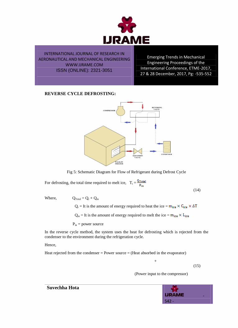
REVERSE CYCLE DEFROSTING:
Fig 5: Schematic Diagram for Flow of Refrigerant during Defrost Cycle
For defrosting, the total time required to melt ice, Tt =
(14)
Where, QTotal = Qr + Qm
Qr = It is the amount of energy required to heat the ice =
Qm = It is the amount of energy required to melt the ice =
Pin = power source
In the reverse cycle method, the system uses the heat for defrosting which is rejected from the
condenser to the environment during the refrigeration cycle.
Hence,
Heat rejected from the condenser = Power source = (Heat absorbed in the evaporator)
+
(15)
(Power input to the compressor)
INTERNATIONAL JOURNAL OF RESEARCH IN AERONAUTICAL AND MECHANICAL ENGINEERING
WWW.IJRAME.COM ISSN (ONLINE): 2321-3051
Emerging Trends in Mechanical Engineering Proceedings of the
International Conference, ETME-2017, 27 & 28 December, 2017, Pg: -535-552
Suvechha Hota
- 543 -
But generally, some power loss occurs due to natural convection in the condenser because the
atmospheric air flows through the finned condenser coils. Heat loss in the condenser,
Qloss =
(16)
Where,
(17)
The empirical correlation for Nusselt number for vertical plate may be used for vertical cylinder.
Hence the Nusselt correlation equation for turbulent free convection in vertical plates is given by
the following equation,
(18)
The Rayleigh number, Ra = Gr. Pr
The Grashof number, Gr =
To calculate the heat transfer through the condenser coil, it is very necessary to calculate the
LMTD (Logarithmic Mean Temperature Difference) of the vapour refrigerant which is at 60

INTERNATIONAL JOURNAL OF RESEARCH IN AERONAUTICAL AND MECHANICAL ENGINEERING
WWW.IJRAME.COM ISSN (ONLINE): 2321-3051
Emerging Trends in Mechanical Engineering Proceedings of the
International Conference, ETME-2017, 27 & 28 December, 2017, Pg: -535-552
Suvechha Hota
- 544 -
Figure 6 - Diagram of Temperature Distribution for Condenser
As 60% of the heat losses due to the natural convection process through the condenser coil in
defrost cycle, so reverse cycle defrosting requires a bypass line from compressor to the evaporator
directly by means of a solenoid valve.
ELECTRIC DEFROSTING:
The total energy required to melt the frost is same in both reverse cycle defrosting and electric
defrosting. The power input is 200 W by the heater. Some amount of heat losses to the air inside the freezer due to natural convection. As shown in the figure the electrical heaters are the
horizontal cylinders. Hence the empirical correlation for Nusselt number for horizontal cylinders
is given by the following equation.
Nu = = Ra 1012 (19)
INTERNATIONAL JOURNAL OF RESEARCH IN AERONAUTICAL AND MECHANICAL ENGINEERING
WWW.IJRAME.COM ISSN (ONLINE): 2321-3051
Emerging Trends in Mechanical Engineering Proceedings of the
International Conference, ETME-2017, 27 & 28 December, 2017, Pg: -535-552
Suvechha Hota
- 545 -
RESULTS AND DISCUSSION
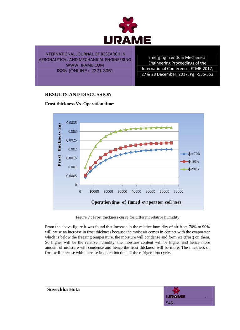
Frost thickness Vs. Operation time:
Figure 7 : Frost thickness curve for different relative humidity
From the above figure it was found that increase in the relative humidity of air from 70% to 90%
will cause an increase in frost thickness because the moist air comes in contact with the evaporator
which is below the freezing temperature, the moisture will condense and form ice (frost) on them.
So higher will be the relative humidity, the moisture content will be higher and hence more
amount of moisture will condense and hence the frost thickness will be more. The thickness of
frost will increase with increase in operation time of the refrigeration cycle.
INTERNATIONAL JOURNAL OF RESEARCH IN AERONAUTICAL AND MECHANICAL ENGINEERING
WWW.IJRAME.COM ISSN (ONLINE): 2321-3051
Emerging Trends in Mechanical Engineering Proceedings of the
International Conference, ETME-2017, 27 & 28 December, 2017, Pg: -535-552
Suvechha Hota
- 546 -
Heat Transfer Vs. Frost Thickness:
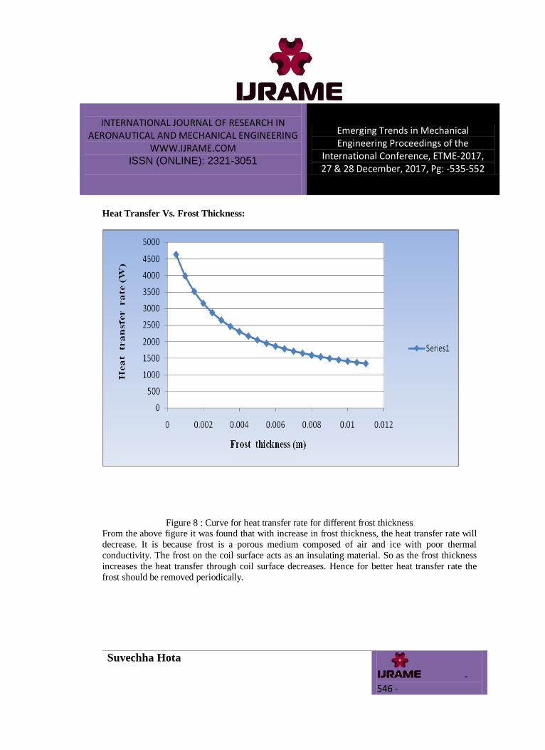
Figure 8 : Curve for heat transfer rate for different frost thickness From the above figure it was found that with increase in frost thickness, the heat transfer rate will
decrease. It is because frost is a porous medium composed of air and ice with poor thermal
conductivity. The frost on the coil surface acts as an insulating material. So as the frost thickness
increases the heat transfer through coil surface decreases. Hence for better heat transfer rate the
frost should be removed periodically.
INTERNATIONAL JOURNAL OF RESEARCH IN AERONAUTICAL AND MECHANICAL ENGINEERING
WWW.IJRAME.COM ISSN (ONLINE): 2321-3051
Emerging Trends in Mechanical Engineering Proceedings of the
International Conference, ETME-2017, 27 & 28 December, 2017, Pg: -535-552
Suvechha Hota
- 547 -
Frost Thickness Vs. Heat Transfer:
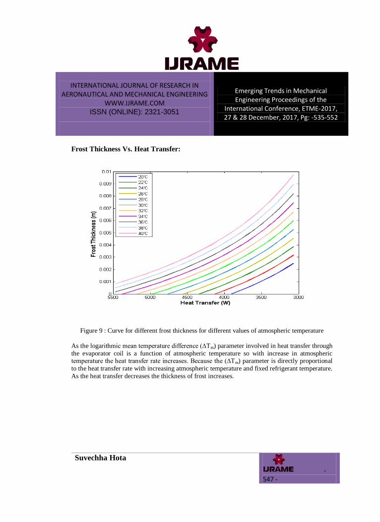
Figure 9 : Curve for different frost thickness for different values of atmospheric temperature
As the logarithmic mean temperature difference (∆Tm) parameter involved in heat transfer through
the evaporator coil is a function of atmospheric temperature so with increase in atmospheric temperature the heat transfer rate increases. Because the (∆Tm) parameter is directly proportional
to the heat transfer rate with increasing atmospheric temperature and fixed refrigerant temperature.
As the heat transfer decreases the thickness of frost increases.
INTERNATIONAL JOURNAL OF RESEARCH IN AERONAUTICAL AND MECHANICAL ENGINEERING
WWW.IJRAME.COM ISSN (ONLINE): 2321-3051
Emerging Trends in Mechanical Engineering Proceedings of the
International Conference, ETME-2017, 27 & 28 December, 2017, Pg: -535-552
Suvechha Hota
- 548 -
Frost Thickness Vs. Heat Transfer:
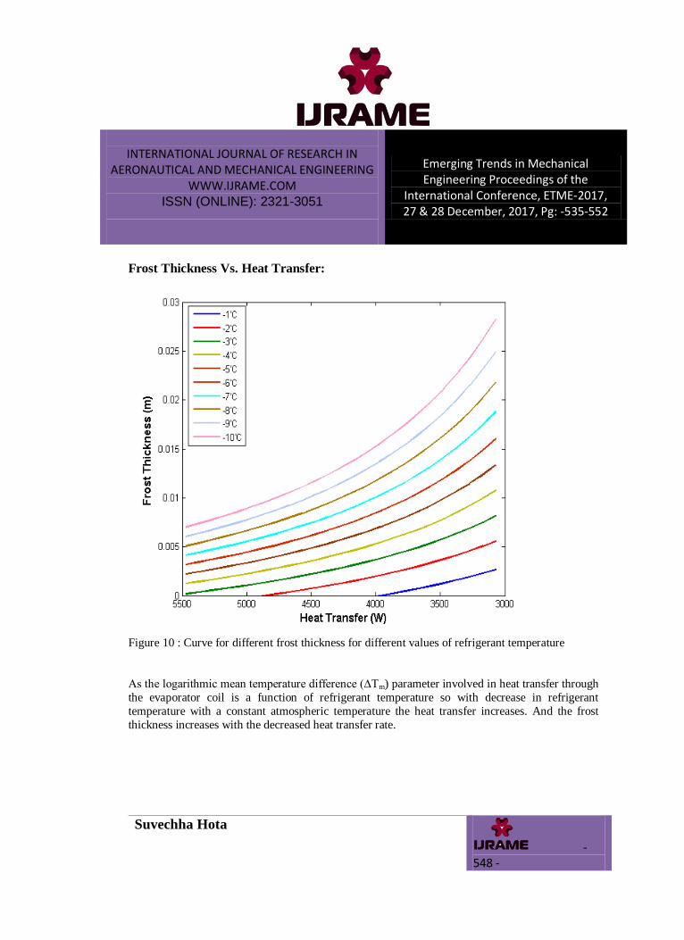
Figure 10 : Curve for different frost thickness for different values of refrigerant temperature
As the logarithmic mean temperature difference (∆Tm) parameter involved in heat transfer through
the evaporator coil is a function of refrigerant temperature so with decrease in refrigerant
temperature with a constant atmospheric temperature the heat transfer increases. And the frost
thickness increases with the decreased heat transfer rate.
INTERNATIONAL JOURNAL OF RESEARCH IN AERONAUTICAL AND MECHANICAL ENGINEERING
WWW.IJRAME.COM ISSN (ONLINE): 2321-3051
Emerging Trends in Mechanical Engineering Proceedings of the
International Conference, ETME-2017, 27 & 28 December, 2017, Pg: -535-552
Suvechha Hota
- 549 -
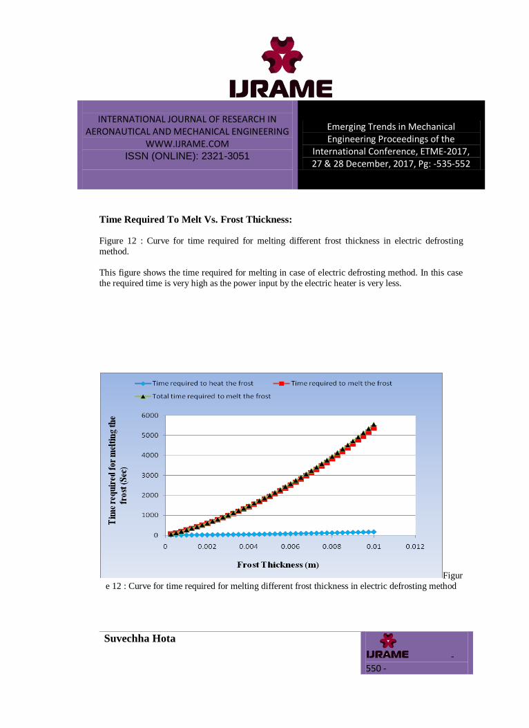
Time Required To Melt Vs. Frost Thickness:
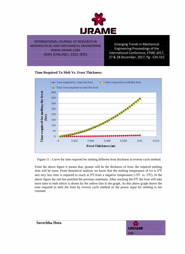
Figure 11 : Curve for time required for melting different frost thickness in reverse cycle method.
From the above figure it means that, greater will be the thickness of frost, the required melting
time will be more. From theoretical analysis we know that the melting temperature of ice is 0
and very less time is required to reach at 0 from a negative temperature (-3 to -5 ). In the
above figure the red line justified the previous statement. After reaching the 0 the frost will take
more time to melt which is shown by the yellow line in the graph. As this above graph shows the
time required to melt the frost by reverse cycle method so the power input for melting is not
constant.
INTERNATIONAL JOURNAL OF RESEARCH IN AERONAUTICAL AND MECHANICAL ENGINEERING
WWW.IJRAME.COM ISSN (ONLINE): 2321-3051
Emerging Trends in Mechanical Engineering Proceedings of the
International Conference, ETME-2017, 27 & 28 December, 2017, Pg: -535-552
Suvechha Hota
- 550 -
Time Required To Melt Vs. Frost Thickness:
Figure 12 : Curve for time required for melting different frost thickness in electric defrosting
method.
This figure shows the time required for melting in case of electric defrosting method. In this case
the required time is very high as the power input by the electric heater is very less.
Figur
e 12 : Curve for time required for melting different frost thickness in electric defrosting method
INTERNATIONAL JOURNAL OF RESEARCH IN AERONAUTICAL AND MECHANICAL ENGINEERING
WWW.IJRAME.COM ISSN (ONLINE): 2321-3051
Emerging Trends in Mechanical Engineering Proceedings of the
International Conference, ETME-2017, 27 & 28 December, 2017, Pg: -535-552
Suvechha Hota
- 551 -
CONCLUSION
In this study one 225 liter (1.5 TR) refrigerator is considered for the theoretical study of different
parameters during frosting and defrosting in case of both reverse cycle and electric defrosting
method. From the figure 4.2 (Curve for heat transfer rate for different frost thickness) it is
concluded that up to 3 mm frost thickness the heat transfer decreases drastically. And after 3 mm
thickness of frost the heat transfer gradually decreases. So particularly for this study the defrost
cycle starts at 3 mm of frost thickness. With a relative humidity of 90% and air mass velocity of 2
Kg/ hr m2 inside the refrigerator, the refrigeration system takes an operation time of 8 hrs to form
3 mm of frost thickness as shown in figure 4.1. Hence the defrost cycle is 3 per day. In this study
the heat rejection from the condenser is due to forced convection by means of a blower because the complete heat rejection increases the system efficiency. But in case of reverse cycle defrosting
it is possible to flow the hot gas through the same path as in refrigeration cycle with compressor in
working condition and other components in non-working condition. But the major disadvantage of
this path is 60% of heat is rejected by natural convection through the condenser tube to the
atmosphere. So the reverse cycle method requires another bypass line from the compressor to the
evaporator directly as a result of which this method uses maximum heat as power source for
defrosting. Hence it is concluded that maximum is the power required minimum will be the
melting time. In the figure 4.5 and 4.6 it is shown that to melt 3 mm thickness reverse cycle
method takes 50 sec whereas electric defrosting method takes 18 min. From the economical
analysis of both the defrosting method, a conclusion can be drawn that reverse cycle defrosting is
faster and economical than the electric defrosting method.
REFERENCES
[1] Abdullah H. M. AlEssa1,2,*, Bassam Al-Zgoul2 “ Building Up of Frost Depending Upon Conditions of Air Cooler Operation” International Journal of Mechanics and Applications 2012, 2(2): 1-4.
[2] Cláudio MELO*, Fernando T.KNABBEN, Paula V. PEREIRA “An Experimental Study on Defrost
Heaters Applied to Household Refrigerators “International Refrigeration and Air Conditioning
Conference, July 16-19, 2012 [3] Dawood Amir Ali, M.S., R. R. Crawford “The Effects of Frost Formation on the
Performance of Domestic Refrigerator-Freezer Finned-Tube Evaporator Coils” Department of Mechanical and Industrial Engineering University of illinois at Urbana-Champaign, 1992.
INTERNATIONAL JOURNAL OF RESEARCH IN AERONAUTICAL AND MECHANICAL ENGINEERING
WWW.IJRAME.COM ISSN (ONLINE): 2321-3051
Emerging Trends in Mechanical Engineering Proceedings of the
International Conference, ETME-2017, 27 & 28 December, 2017, Pg: -535-552
Suvechha Hota
- 552 -
[4] Hwan-Jong Choi a,b, Byung-Soon Kim b, Donghoon Kang b, Kyung Chun Kim a,* “Defrosting
method adopting dual hot gas bypass for an air-to-air heat pump” Applied Energy 88 (2011) 4544–4555.
[5] JuliusH. Rainwater “Five Defrost Methods For Commercial Refrigeration” march2009.
[6] Kamal A. R. Ismail1, Fatima A. Morais Lino1, Carlos T. Salinas1, Luiz Vicente Scalon2, Raquel
da Cunha Ribeiro da Silva1 “Numerical and Experimental Investigation on Frost Formation on Cold Cylinders” IOSR Journal of Engineering (IOSRJEN) Vol. 05, Issue 03 (March. 2015), ||V2|| PP 43-58.
[7] Li Zhang, Takeshi Fujinawa, Michiyuki Saikawa “Theoretical study on a frost-free household
refrigerator-freezer” International Journal of Refrigeration 2-10-2015.
[8] Mahesh M. Rathore“Engineering Heat and Mass Transfer” 2006. [9] Minglu Qu a, Dongmei Pan a, Liang Xia a,*, Shiming Deng a, Yiqiang Jiang b “A study of the
reverse cycle defrosting performance on a multi-circuit outdoor coil unit in an air source heat pump – Part II: Modelling analysis” Applied Energy 91 (2012) 274–280.
[10] Prabal Talukdar “ Natural/Free convection ” Department of Mechanical Engineering Department of
Mechanical Engineering IIT Delhi. [11] Pradeep Bansal, David Fothergill, Ryan Fernandes “Thermal analysis of the defrost cycle in a
domestic freezer” international journal of refrigeration 33(2010) 589-599. [12] Ramesh Chandra Arora ”Refrigeration and air conditioning” January 2011. [13] Raquel da Cunha Ribeiro da Silva, Carlos T. Salinas, Kamal A. R. Ismail “Numerical prediction of
frost thickness growth over a cold cylinder” The 4th International Congress on University-Industry Cooperation – Taubate, SP – Brazil – December 5th through 7th, 2012.
[14] Service Engineers‟ Section of the Institute of Refrigeration “Defrosting” Technical Bulletin No3,
October 2000.
Related Documents