FACULTY OF ENGINEERING DEPARTMENT OF TEXTILE ENGINEERING Comparative study between100% cotton yarn & cotton-polyester blend yarn Submitted by: Nadim Haider Maruf ID: 132-32-227 Supervisor: Prof. Dr. Md. Mahbubul Haque Head Dept. of TE Daffodil International University Dissertation submitted to the Department of Textile Engineering of Daffodil International University in partial fulfillment of the requirement for the Degree of Masters of Science in Textile Engineering ©daffodil international university

Welcome message from author
This document is posted to help you gain knowledge. Please leave a comment to let me know what you think about it! Share it to your friends and learn new things together.
Transcript

FACULTY OF ENGINEERING
DEPARTMENT OF TEXTILE ENGINEERING
Comparative study between100% cotton yarn & cotton-polyester blend yarn
Submitted by: Nadim Haider Maruf ID: 132-32-227
Supervisor: Prof. Dr. Md. Mahbubul Haque Head
Dept. of TE Daffodil International University
Dissertation submitted to the Department of Textile Engineering of Daffodil International
University in partial fulfillment of the requirement for the Degree of Masters of Science in
Textile Engineering
©daffodil international university
APPROVAL
I hereby declare that the work which is being presented in this thesis entitled,
“Comparative study between 100% cotton yarn & cotton-polyester blend yarn” is
original work of my own, has not been presented for a degree of any other university
and all the resource of materials uses for this thesis have been acknowledged.
This is to certify that the above declaration made by the candidate is correct to the best of my knowledge.
_______________________ _________________
Prof. Dr. Md. MahbubulHaque Date
Supervisor
©daffodil international university i

DECLARATION
I hereby declare that the work which is being presented in this thesis entitled,
“Comparative study between 100% cotton yarn & cotton-polyester blend yarn” is
original work of my own, has not been presented for a degree of any other university
and all the resource of materials uses for this thesis have been acknowledged.
_______________________ _________________
Nadim Haider Maruf Date
This is to certify that the above declaration made by the candidate is correct to the best of my knowledge.
_______________________ _________________
Prof. Dr. Md. MahbubulHaque Date
Supervisor
©daffodil international university ii

ACKNOWLEDGEMENT
Above all, I praise the almighty Allah who gave me His enabling grace to successfully
complete this research work.
With sincerity, I extend my warm and deep appreciation and gratitude to my supervisor, Dr.
Md. MahbubulHaquefor his unreserved guidance and support to come up with this
research work. Being working with him, I have not only earned valuable knowledge but was
also inspired by his innovativeness which helped to enrich my experience to a greater
extent. His ideas and way of working was truly remarkable. I believe that this research could
not be finished if he did not help me continuously.
I am thankful to Md. Mazedul Islam Mazed, General Manager, Yasmin spinning mills ltd.
for his kind help and advice.
I would also like to thank all who responded to my questionnaires and interviews, which
helped me in coming up with this research.
I am grateful to my all colleagues for their encouragement for this research work.
Finally, I express my sincere gratitude to my father, mother, brother, sister and sister-in-law for their continuous support, ideas and love during my studies. -The Author
©daffodil international university iii
ABSTRACT
This study makes an assessment on difference in manufacturing of cotton yarn & cotton-
polyester blend yarn. To undertake this study, the following three yarns were produced
e.g.100% cotton yarn, 50/50 cotton & polyester blend yarn and 20/80 cotton & polyester
blend yarn were produced. After that all the three yarns were tested for various parameters.
It was observed that as the percentage of polyester increases the U% i.e. the irregularity in
the sliver & roving decreases. For uniform blending of cotton-polyester more draw frame
was required than that was required for 100% cotton process. In the roving frame it was
possible to maintain higher flyer speed and lower twist for PC & TC. Between TC & PC the
flyer speed was higher and twist was lower for TC than PC. It was observed that
imperfections (IPI) decreased with the increase of share or % of polyester in the yarns. The
yarn strength increases with the increase of polyester percentage in the yarns. Since the % of
polyester is higher in TC therefore its strength was higher than that of PC yarns. Finally it
was possible to maintain higher spindle speed and lower twist for PC & TC. Further to this
the spindle speed was higher and twist was lower for TC than PC.
©daffodil international university
iv

Table of Contents DECLARATION………………………………………………………………………………….i ACKNOWLEDGEMENT………………………………………………………………………...ii ABSTRACT……………………………………………………………………………………...iii TABLE OF CONTENTS…………………………………………………………………....iv LIST OF TABLES…………………………………………………………………………...v
LIST OF FIGURES…………………………………………………………………………vi
1. INTRODUCTION ............................................................................................................ 1
1.1 Research Background .................................................................................................... 1
1.2 Research Objective ........................................................................................................ 2
1.3 Significance of the Study ............................................................................................... 2
1.4 Scope of the Study ......................................................................................................... 2
2. LITERATURE REVIEW ................................................................................................. 3
2.1 Evolution of Quality ...................................................................................................... 3
2.2 Blending ......................................................................................................................... 4
2.3 Blow room ..................................................................................................................... 5
2.4 Carding Machine ........................................................................................................... 6
2.5 Draw Frame ................................................................................................................... 9
2.6 Simplex Machine ......................................................................................................... 11
2.7 Ring spinning Machine ................................................................................................ 11
2.8 Auto corner .................................................................................................................. 13
2.9 High Volume Instrument (HVI) .................................................................................. 13
2.10 Uster Evenness Tester................................................................................................ 14
3. Methodology .................................................................................................................. 15
3.1 Blow room ................................................................................................................... 15
3.2 Carding ........................................................................................................................ 17
3.3 Draw frame .................................................................................................................. 21
3.4 Simplex ........................................................................................................................ 26
3.5 Ring frame ................................................................................................................... 29
3.6 Auto-cone .................................................................................................................... 35
3.7 Testing of blend ratio of yarns ..................................................................................... 41
4. Discussion of Results ..................................................................................................... 43
©daffodil international university v
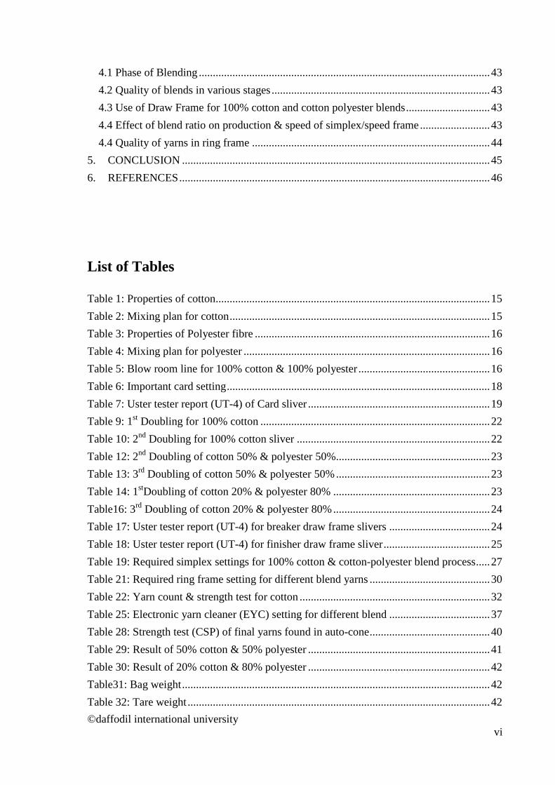
4.1 Phase of Blending ........................................................................................................ 43
4.2 Quality of blends in various stages .............................................................................. 43
4.3 Use of Draw Frame for 100% cotton and cotton polyester blends .............................. 43
4.4 Effect of blend ratio on production & speed of simplex/speed frame ......................... 43
4.4 Quality of yarns in ring frame ..................................................................................... 44
5. CONCLUSION .............................................................................................................. 45
6. REFERENCES ............................................................................................................... 46
List of Tables Table 1: Properties of cotton .................................................................................................. 15
Table 2: Mixing plan for cotton ............................................................................................. 15
Table 3: Properties of Polyester fibre .................................................................................... 16
Table 4: Mixing plan for polyester ........................................................................................ 16
Table 5: Blow room line for 100% cotton & 100% polyester ............................................... 16
Table 6: Important card setting .............................................................................................. 18
Table 7: Uster tester report (UT-4) of Card sliver ................................................................. 19
Table 9: 1st Doubling for 100% cotton .................................................................................. 22
Table 10: 2nd Doubling for 100% cotton sliver ..................................................................... 22
Table 12: 2nd Doubling of cotton 50% & polyester 50% ....................................................... 23
Table 13: 3rd Doubling of cotton 50% & polyester 50% ....................................................... 23
Table 14: 1stDoubling of cotton 20% & polyester 80% ........................................................ 23
Table16: 3rd Doubling of cotton 20% & polyester 80% ........................................................ 24
Table 17: Uster tester report (UT-4) for breaker draw frame slivers .................................... 24
Table 18: Uster tester report (UT-4) for finisher draw frame sliver ...................................... 25
Table 19: Required simplex settings for 100% cotton & cotton-polyester blend process ..... 27
Table 21: Required ring frame setting for different blend yarns ........................................... 30
Table 22: Yarn count & strength test for cotton .................................................................... 32
Table 25: Electronic yarn cleaner (EYC) setting for different blend .................................... 37
Table 28: Strength test (CSP) of final yarns found in auto-cone ........................................... 40
Table 29: Result of 50% cotton & 50% polyester ................................................................. 41
Table 30: Result of 20% cotton & 80% polyester ................................................................. 42
Table31: Bag weight .............................................................................................................. 42
Table 32: Tare weight ............................................................................................................ 42
©daffodil international university vi

List of Figures
Figure 1: Uster tester report (UT-4) of Card sliver ................................................................ 20
Figure 2: Irregularity of different breaker sliver .................................................................... 25
Figure 3: Irregularity of different finisher sliver ................................................................... 25
Figure 6: Required Twist per inch (TPI) in ring frame for different blend yarns ................. 31
Figure 7: Yarn strength variation found in ring frame .......................................................... 33
Figure 8: Yarn faults in different blend ................................................................................. 34
Figure 9: Winding speed for formation different yarns packages ......................................... 36
Figure 13: Yarn strength variation found in auto-cone ......................................................... 41
©daffodil international university vii
1. INTRODUCTION 1.1 Research Background The globalization of the market and the rapid improvements in information flow has made competition in manufacturing industries to be fierce worldwide. As a result, industries such as the garment industry are facing the greatest challenge in history because of the rapidly changing business environment with respect to global competition, market performance, and changing technology. Garment is a fashion product that is influenced by social trends and global economic environments. While people have been manufacturing cotton for various uses for hundreds of years, polyester is a fairly recent phenomenon. Developed in the 1950s from chemically treated petroleum, polyester was intended as a fabric that would be inexpensive to mass manufacture and durable under a variety of conditions. It did not take long to test combinations of polyester and other fabrics and, by the late 1950s, poly cotton blends were available. Its use as a stretch fabric, especially, helped lead to poly cotton fabrics becoming a common clothing textile.Polyester was often blended with other fibres to give the best of both worlds. With cotton it combined breathability with easy-care convenience. To the warmth of wool it added an improved drape, wash ability and comfort. It strengthened rayon’s and improved their crease-resistance. However it still had a comparatively small market share compared to other synthetics nylon, acrylic and Rayon (initially it was blended only with other synthetics - it wasn't until the late 50s that manufacturers hit upon the poly-cotton blend). Polyester was introduced into cotton fabrics to curb some of the problems people have when working with or wearing pure cotton. Cotton wrinkles easily, can stretch out and lose its color in the wash and can stain easily, due to the absorptive qualities of natural fibres. Polyester, on the other hand, retains its shape and color and can easily be cleaned, due to the various types of treatments that may be applied to the fabric during the manufacturing process. Poly cotton is known for its durability, as it can easily be thrown in the washing machine and retains its shape better than items made of pure cotton. Poly cotton blends are also known for their comfort. Poly cotton should have a higher percentage of cotton than polyester fabrics in the weave. The cotton allows the fabric to breathe and retain the softness of the natural fibres, while maintaining the structure enforced by the polyester. The polyester in the poly cotton blend can lead the fabric to pill over time, making the fabric look worn. While an item with a high cotton percentage (more than 85 per cent) can retain the softness of cotton, anything lower may feel too synthetic and lose the benefits of the cotton within the fabric. There is still a stigma attached to polyester fabrics, due to their mass manufacture and often lack of aesthetic quality, and many people will refuse to buy a poly cotton blend.
Uses of Poly Cotton:
Poly cotton can be used to make a variety of everyday items, from upholstery and bedding to sportswear and denim. Poly cotton is particularly used for items expected to get a lot of wear. Sheets and sofa covers, as well as track suits, T-shirts and hoodies, are often made in poly cotton blends, as these items require both comfort and durability
©daffodil international university 1
1.2 Research Objective The main objective of this study is to critically examine and identify the main differences
during processing cotton yarn & cotton-polyester blend yarn.
Furthermore, the research targeted to achieve the following specific objectives:
• To study and identify the difference in process during processing.
• Understanding the differences in machine setting.
• To check the differences in testing result.
• To help the spinner in cotton-polyester blend manufacturing.
• Propose appropriate measures to improve the quality of products.
1.3 Significance of the Study As in this competition era, acompany must be aware about the customer needs&what a
consumer expects from the company. A company must have this information or a customer
database if it wants to stay in the market to competitive edge in the market. After conducting
this study we must be able to understand actual difference between cotton & cotton-
polyester blend processing, what are the factors must be considered during processing. By
which company can formulate the strategies as per the customer needs & deliver them the
products which consumer want from the company, which will be profitable for the
company.
1.4 Scope of the Study If we talk about the scope of this study in future then the scope of such study is very wider.
Scope of the study is that after gathering the information about the manufacturing of cotton
& cotton-polyester blend, who like to purchase thecotton-polyester blend yarn. After
studying the factors which influence them to go with that specific quality, it includes
production & quality. This study will be helpful for the companies who are in this business
segment of yarn manufacturing. They will be able to know the needs of the buyer& what
will be the products & services which will help them to change the non-user into user of
their yarn& retain their existing customer by providing them the products which they want
from the company.
©daffodil international university
2
2. LITERATURE REVIEW
2.1 Evolution of Quality Yarn: A product of substantial length & relatively small cross-section consisting of fibers and/ or filaments with or without twist. Yarn is a long continuous length of interlocked fibers, suitable for use in the production of textiles, Sewing, Knitting, Weaving & rope making. Yarn can be made from any number of synthetic or natural fibers. Yarn may be defined as arrangement of fibers uniformly to a continuous mass of fiber bound together by twist without twisting. A generic term for a continuous strand spun from a group of natural or synthetic staple fibers, or filaments, used in weaving, knitting to from textile fabrics. Types of yarn: a) Spun Yarn: A yarn consisting of fiber of regular or irregular staple length usually bound together by twist. b) Filament yarn: A yarn of an indefinite or extreme length such as found naturally in silk. Manufactured fibers are extruded into filaments that are converted into filament yarn, staple or tow. Yarn can be classified according to
(1) Length of fiber: (a) Spun yarn (Short staple and Long staple) (b) Filament yarn (Monofilament, Multifilament) (2) No of strand: (a) single yarn (b) Ply or Double yarn (c) Cable yarn
Ply Yarn: All yarns are single ply unless twisted with another yarn. Terms used are: 2 ply if two yarns are twisted together & 3 ply if three are twisted. Piled yarns are used to make yarns stronger. In the jeans wear industry it has become important to ply yarns in piece dyed fabrics that are intended to endure a long stone wash cycle. Cable Yarn: A cable yarn is made up of two or smaller piled yarns twisted together. The easiest cable yarn is a 4-ply. 3) Spinning System:
(a) Ring yarn (b) Rotor yarn (c) Air jet yarn (d) Worsted yarn e) Woolen yarn
4) Types of fiber blend e.g. CVC, PC:
5) Process sequence used e.g. (a) Carded yarn (b) Combed yarn
©daffodil international university 3

2.2 Blending Raw materials used in spinning mill are always inhomogeneous in their characteristics. In part, this is inevitable owing to the different cultivation conditions of natural fibres and different production conditions for synthetic fibres. It is done in order to influence the end product and the process. Blending is performed mainly in order to:
• Give the required characteristics to the end product, for example, blending of synthetic fibres with natural fibres produces the desired easy-care character.
• Compensate for variations in the characteristics of the raw materials. • Hold down raw material cost • Influence favorably the behavior of the raw material during processing • Achieve effects by varying color, fibre characteristics and so on.
Types of blending:
• Bale Mixing: before the blow room • Flock blending: within the blow room • Lap blending: using scutchers • Web blending: at ribbon lap machine or blending at drawframe • Sliver blending: at drawframe, the sliver-lap machine, or at the comber • Fibre blending: at card or the OE spinning machine • Roving blending: at the ring spinning machine
Flow chart for 100% cotton (carded) yarn manufacturing: Input Process stage Output Raw cotton Blow room Cotton as chute mat Chute mat Carding Sliver Sliver Breaker Draw Frame Sliver Sliver Finisher Draw Frame Sliver Sliver Simplex Roving Roving Ring frame Yarn Yarn Auto-cone Yarn package Flow chart for cotton-polyester blend yarn manufacturing: Input Process stage Output Raw cotton Blow room Cotton as chute mat Chute mat Carding Sliver Sliver Breaker Draw Frame Sliver Sliver Finisher Draw Frame Sliver Sliver Simplex Roving Roving Ring frame Yarn Yarn Auto-cone Yarn package
©daffodil international university 4
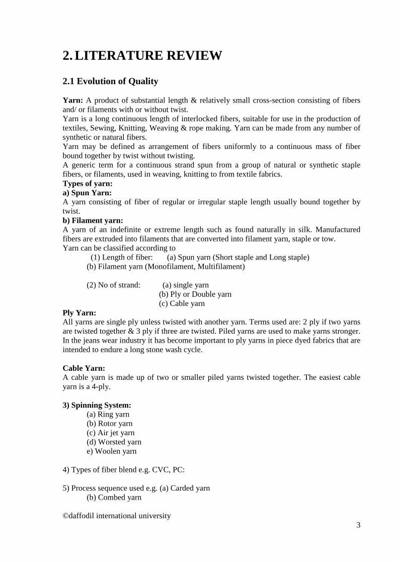
2.3 Blow room The section in where the supplied compressed fibre bales are turned into a uniform lap of particular length or small fibre tufts by opening cleaning, blending or mixing is called blow room section. It is the first section of spinning. Objects of blow room:
• To open the baled fibers into small tufts which allow foreign matter to be separated from the fibers & prepare the material for easy carding.
• To clean the fibers by removing the foreign matter as the waste. • To mix thoroughly the different component fibers of a mixing so as to give a
homogeneous blending. • To form a compact & uniform sheet of fibers the lap. or • To feed blended material to the chute feed system.
Basic operations involved in the blow room:
• Opening by the action of opposite spike • Cleaning by the action of beater • Dust removal by action of air current • Blending or Mixing • Formation of carding lap or even feed of the materials to the card by regulating
action.
Rieter Blow Room line: Unifloc B 12 Uniclean B11 UnimixB60 UniflexB70 FFD (Vission Shield, Jossi) Condenser A21 Trutzschler Blow Room line: Blendomat BO
©daffodil international university 5
Precleaner CLP Multimixer MPM Fine Cleaner CLC FFD (SP EP, Securo, Prop, Securomat) Dustex
2.4 Carding Machine In 1748 Lewis Paul of Birmingham, England invented the hand driven carding machine.The name card is derived from the Latin ‘Carduus’. It means thistle, the spiked fruit of which was used for plucking fibres apart in earlier time. The proverbs of experts-
• “The card is the heart of the spinning mill” • ‘Well-carded is half-spun’- demonstrate the immense significance of carding for the
final result of the spinning operation. These proverbs demonstrate the immense significance of carding for the final result of the spinning operation. The importance of carding is still greater where new spinning systems are concerned. The considerable influence of the card on yarn quality arises from the very complex series of events in the process itself, and also from the pressure to adopt an extremely high production rate on economic ground. Carding is defined as the reduction of entangled mass of fibers to filmly web by working them between two closely spaced relatively moving surfaces clothed with sharp points. It is a preliminary process in spun yarn technology just after blow room process. Tasks of carding machine:
• Opening to individualize the fibres. • Elimination of remaining impurities and dust. • Disentangling of neps. • Elimination of short fiber. • Fiber orientation or alignment. • Producing a uniform continuous strand called sliver. • Fibre blending
Different types of cards
• Revolving flat card: Card designed for processing of relatively shortfibres have flats circulating on an endless path. So they are referred as revolving flat cards. ©daffodil international university
6

©daffodil international university 7
• Tandem card: Tandem card consists of two individual cards joined together to make up a unit, in which the doffer of the first cards feeds fiber material to the taker-in of the second card. e.g.: Crosrol tandem card.
• Super card: Feature:
• Two or three taker-in instead of one. • Cylinder speed up to 800 rpm. • Increase of the operating width 1.5 m • Production 150 kg/ hour.
Functional Zone of carding Generally there are four functional zone of carding:
• Feeding Zone • Cleaning Zone • Carding Zone • Sliver formation Zone
Card feeding is of two types:
• Lap Feed (Conventional) • Chute feed (Modern)
(a) Single chute feed system (b) Double chute feed system Advantages of lap feed system
• Linear density of the lap is very good and easier to maintain (uniformity). • The whole installation is very flexible. • The deviation of card output will be nil as laps can be rejected. • Autolevellers are not required, hence investment cost and maintenance cost is less.
Disadvantages of lap feed system
• Transportation of lap needs more manual efforts (more labour). • Lap run out is an additional source of fault, as it should be replaced by a new lap. • More good fiber loss during lap change. • More load on the taker-in as laps are heavily compressed.
Advantages of Chute feed system
• High performance of carding due to high degree of openness of feed web. • Labour requirement is less due to no lap transportation and lap change in cards. • This system eliminates additional burden on the taker-in to open the compressed lap. • Elimination of lap waste up to 3%.
Disadvantages of chute feed system:
• Flock feeding is the only solution for high production cards. • Linear density of the web to the card is not as good as lap.
©daffodil international university 8
• Installation is not flexible. • Autoleveller is a must, hence investment cost and maintenance cost is more
Action that process in carding machine Carding machine operates by performing several actions. Some important actions are discussed below-
• Carding action: When the wire point of two closed surface are inclined o the opposite direction and fibre tuft weight is reduced by the relative notion of the two surface then the action is called carding action. Here the wire point works as point against point. Carding action occurs between cylinder and flat.
• Stripping action: When the wire point of two closed surface are inclined to the
opposite direction and both the surface rotate to the opposite direction then the action is called stripping action. Here the point works as point against back. Stripping action occurs between Taker-in and cylinder.
• Doffing action: When the wire point between two closed surfaces are inclined to the
same direction and both the surfaces rotate to the opposite direction then the action is called doffing action.As fibre transferred is occurred by this action as transfer action. Doffing action occurs between cylinder and doffer.
Basic elements of chute feed system
• Conveyer system. • Proper control of air pressure. • A mechanism to feed the material at uniform weight per unit length. • A delivery system to feed material to card feed rollers. • A sensing mechanism to keep a certain amount of material as reserve.
Carding machine Trutzschler carding machine: Model: TC03, DK903, DK803, DK 760 Rieter carding machine: Model: C60, C51, C50 2.5 Draw Frame Drawing: It is a process of yarn manufacturing in which the sliver is elongated when passes through pairs of rollers, each pair moving faster than the previous one.This permits combination of several slivers. These slivers are drawn and elongated to straighten and create greater uniformity. Objects of draw frame:
• To straighten the fibres that are hooked and crimped. • Parallelization of fibres
©daffodil international university 9

• Production of sliver having uniform weight per unit length by drafting. • Reduce irregularities of sliver by doubling. • To remove dust from the slivers. • To make perfect blending of the component
Requirement of drafting arrangement: The drafting arrangement is the heart of drawframe. The requirements of drafting arrangement are given below:
• Simple, uncomplicated construction. • Stable design with smooth running of the roller. • A mode of operation giving a high quality product even a high running speed. • High degree of flexibility • Optimal control over the movement of fibres during the drafting operation. • High precision both of operation and adjustment. • Rapid and simple adjustability of roller spacing and draft level. • Ease of maintenance and cleaning • Optimal ergonomic design
Factors affecting the draft:
• Mass of fibre in the strand cross-section • Degree of order of the fibre • Shape of the cross- section of the fibre strand. • Compactness of the fibre strand • Adhesion between the fibres depend upon surface structure • Fibre length • Twist in the fibre strand • Evenness of distribution of fibre lengths
Actions involved in draw frame:
• Doubling • Drafting
Doubling: The process of combing two or more slivers into a single form is called doubling. In draw frame machine, generally 6-8 slivers are fed which is converted into one. It is expressed as doubling of draw frame. Drafting system How much no. of roller and it how way arrange is known drafting system. The drafting system is the heart of the draw frame and thus the part which exerts the most decisive influence on quality. Drafting systems: ( Figures from W. Klein)
• 4-over-4 roller drafting system. • 3-over-4 roller drafting system. • 3-over-3 roller drafting system. • 4-over-3 roller drafting system. • 5-over- 4 roller drafting system (Rieter).
©daffodil international university 10
2.6 Simplex Machine Objectives of simplex machine:
• Attenuation of drawn sliver to form roving of required count by drafting. • Insert small amount of twist to give required strength of roving. • Wind the twisted roving on to the bobbin. • Build the roving in bobbin such a form which will facilitate handling, withdrawing
& transfer to the next process. Operation involved in Simplex machine:
• Creeling: To feed the sliver by the help of several rows of driven rollers to the machine.
• Drafting: To reduce the weight per unit length of sliver to make it suitable for ring spinning system.
• Twisting: To insert small amount of twist to give required strength to the roving. • Winding: To wind the twisted roving onto the bobbin. • Building: To build the roving in bobbin such a form which will facilitate handling,
withdrawing & transfer to the next process. • Doffing: To replace an empty bobbin at the place of full bobbin
Manufacturers of simplex machine: There are some manufacturers which manufacture simplex machine. These are given below:
• Rieter – Switzerland (F 15, F35 etc.) • Toyota – Japan (FL-16, FL-100, FL-200) • Lakhsmi Machinery Works – India • China Textile Machinery Works • Marzoli etc.
Necessity of simplex machine: Simplex machine is necessary for two principle reasons. These are given below:
• The first reason is related to the required draft. Sliver is a thick, untwisted fibre strand that tends to be hairy and to create fly. The amount of draft 300-500 is required to convert this to a yarn. The drafting arrangement of ring spinning machine in their present forms are not capable of processing this strand in a single drafting operation to create a yarn.
• The second reason is that draw frame can represent the worst conceivable mode of transport and presentation of feed material to spinning frame.
2.7 Ring spinning Machine The ring spinning machine was first invented in 1828 by the American Thorp. In 1830, another American scientist, Jenk, contributed the traveler rotating on the ring. There have been many development has done in ring spinning machine for the last years but the basic concept remained unchanged.
©daffodil international university 11

Operations involved in ring frame:
• Creeling • Drafting • Twisting • Winding • Building • Doffing
Advantage of Ring spinning system:
• Any type of material (fibre) can be spun • Wide range of count can be processed • It delivers a yarn with optimum characteristics. • Idealized twisting system • It is uncomplicated and easy to operate • Higher yarn strength can be achieved
Disadvantages:
• Low production • Machine generates more heat
Function of ring frame:
• Draft the roving until the required fineness is achieved • Twist the drafted strand to form yarn of required count and strength • Winding the twisted yarn on to the bobbin for suitable storage, transportation and
further processing.
Drafting system:
• Regular drafting without apron- i) Conventional 3 over 3 drafting system ii) Improved drafting system • Apron drafting i) Single Apron- a. Saco Lowel Drafting b. Improved system ii) Double apron- a. Casablanca’s drafting system b. SKF drafting system
Some important models of SKF drafting system:
SKF PK-211 SKF PK-220 SKF PK-225 SKF PK-235 SKF PK-255 SKF PK-265 SKF PK-2025
©daffodil international university 12

Types of drafting system: There are commonly two types of drafting system are used in ring frame:
1) Spring loaded drafting system or Pendulum arm. example: SKF PK 2025 or Texparts 2035
2) Pneumatic drafting system: SKF PK 3025 Difference between pneumatic and pendulum arm drafting system:
Pneumatic drafting system Pendulum arm 1. Loaded by pneumatic pressure i.e. compressed air
1. Loaded by spring
2. Uniform pressure is applied to all drafting rollers
2. Applied pressure in all drafting zones is not uniform
3. Consistent yarn quality is achieved 3. Consistent yarn quality is not achieved 4. Modern drafting system 4. conventional system
2.8 Auto corner Objectives:
• To make a yarn package for selling in the market.
• Detect yarn faults and remove faults from yarn.
• Splice or joint two edges of yarn.
Fault detection of yarn is done by electronic yarn clearer (EYC)
2.9 High Volume Instrument (HVI) The testing of fibres was always of importance to the spinner. It is done by the HVI machine. High volume instrument systems are based on the fibre bundle strength testing, ie, many fibres are checked at the same time and their average values determined. Traditional testing using micronaire, pressley, stelometre, and fibro graph are designed to determine average value for a large number of fibres, the so called fibre bundle tests. In HVI, the bundle testing method is automated. Here, the time for testing is less and so the number of samples that could be processed is increased, quite considerably. The influence of operator is reduced. The HVI testing is attractive due to the classing of cotton and the laying down of a mix in the spinning mill. This HVI testing is suitable for the extensive quality control of all the bales processed in a spinning mill. The mill is in a position to determine its own quality level within a certain operating range. The time for testing per sample is 0.3 minutes. It is best applied to instituting optimum condition for raw material. About 180 samples per hour can be tested and that too with only 2 operators.
©daffodil international university 13
High volume instrument used in bale management system This is based on the categorising of cotton bales according to their fibre quality characteristics. It includes the measurement of the fiber characteristics with reference to each individual bale, separation of bales into classes and lying down of balanced bale mixes based on these classes. The reason for undertaking this work lies in the fact that there is sometimes a considerable variation in the fibre characteristics from one bale to another, even within the same delivery. This variation will result in the yarn quality variation if the bales are mixed in an uncontrolled manner. 2.10 Uster Evenness Tester The instrument by which unevenness (U%) , co-efficient of variation of mass (CVm%), yarn hairiness, imperfection index (IPI) and thick, thin place, nepsetc of yarn, roving sliver can be measured or calculated is called Uster Evenness Tester or Uster Tester 5. The evenness of yarn is an important index of quality control of textiles, so the researches about the yarn evenness test method have been the hotspot in the textile measurement for recent years. In this article, yarn evenness testing by uster evenness tester. The evenness of yarn is one of main indexes to measure the quality of yearns. The unevenness of yarns will deteriorate the mightiness of yarns, and increase the end breakage rate in the spinning, and the increase of the end breakage rate will directly limit the speed of the machines and reduce the productivity. In addition, the unevenness of yarns will seriously influence the appearance quality of textiles. The usual yarn evenness testing methods mainly include the length measurement and weight measurement method, the visual measurement method and the Uster evenness tester method. Because of large computation, the length measurement and weight measurement method is only used in the research works requiring higher nicety or adjusting and measuring unevenness instruments, and it is rarely adopted in general tests. Because the visual measurement method is quick and convenient, and it can comprehensively evaluate the appearance quality of yarns, and it is a very usual method in productions, but it has many deficiencies such as large man-made factor influences, random character, non-objectivity and bad repetition character, and its testing results are hard to be reserved. The Uster evenness tester can get rid of the influence of man-made factors to the testing results, and it can quickly and objectively measure the unevenness of yarns, so it is applied widely. However, as viewed from its testing principle, it still has certain deficiencies. First, the Uster CV value of yarn evenness can only denote the unevenness degree of yarns, but cannot reflect the uneven structure of yarns. Second, the Uster CV value of yarn evenness only considers the average of the unevenness degree of yarns, and cannot reflect the uneven waves with different characters on yarns, i.e. it ignores the discrete character of yarn unevenness. But these uneven waves of yarns would largely influence the unevenness of cloth cover. Third, when measuring blended yarns, because both the properties of fiber materials and the dielectric coefficients are different, and if the blended evenness of fibers in yarns is bad, the capacitance will change, which will influence the CV values. If above factors cannot be controlled effectively, the nicety of the testing result of yarn unevenness will be influenced. Fourth, the nicety of testing values will be impacted by ©daffodil international university
14

the testing conditions (the atmosphere state, the historical reversion condition of samples, the time of humidifying treatment).
3. Methodology The works reported in this thesis is a comparative study of 100% cotton yarn with two cotton-polyester blends of two different blend ratios (shown below). Accordingly three yarns sample were spun and then their properties were tested to make comparison. These samples were compared in every steps of ring spinning. Finally the manufactured yarn is compared for quality & production. The samples are: A. 100% cotton yarn. B. 50% cotton & 50% polyester (PC yarn) C. 20% cotton & 80% polyester (TC yarn) First two stages of yarn manufacturing are Blow room & then Carding. These stages were separate both for 100% cotton & 100% polyester. Card Slivers (100% cotton & 100% polyester) were blend in third stage known as Draw frame according to their percentage.
3.1 Blow room 3.1.1 Processing of 100% cotton 3.1.1.1Cotton mixing: Different cotton fibre characteristics is shown in the table.
Table 1: Properties of cotton
Cotton name Length in mm (HVI) Color (HVI) Fineness (micronaire value)
Bar-kina Faso 29 Light Spotted 3.65
Cameron 28 White 4.50
Ivory 29 Light Spotted 4.10
Togo 29 White 4.20
Table 2: Mixing plan for cotton
Serial no. Cotton type LC no. Weight/bale in kg
Quantity in bales
Mixing quantity in
kg
Mixing %
A Ivory 10075 232 28 6960 63
B Bar-kina 31397 220 06 1320 13
©daffodil international university 15
C Togo 11267 220 05 1100 11
D Cameron 18244 218 06 1308 13
Total 45 10688 100
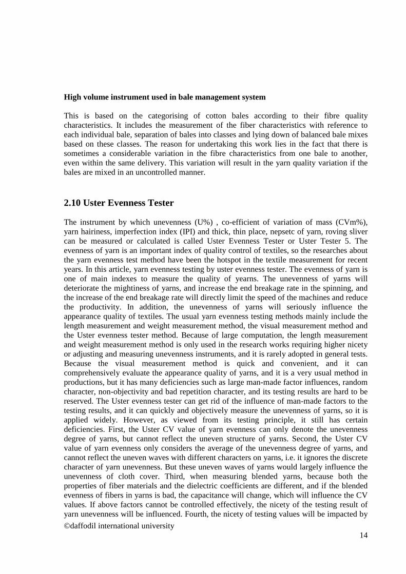
Table 3.1.1.4: Lay down/Mixing plan for cotton in blow room
Total bale: 45
Maximum/group: 3
A B A C A A A C A B A B A D A
D A A A D A B A A A D A C A A
A A D B A C A A D C A A A A B
3.1.2: Processing of Polyester Table 3: Properties of Polyester fibre
Name Color Length Fineness
Virgin China Semi-dull 32 mm 3.95
Table 4: Mixing plan for polyester
PSF type LC no. Weight/bale in kg Mixing quantity
in bale Total weight in
kg
Virgin (China) 50019 380 25 9500
3.1.2.1 Mixing & Lay down plan for Polyester: There is no plan for polyester fibre. Polyester bales are feed one by one manually.
Table 5: Blow room line for 100% cotton& 100% polyester
Cotton 100% Polyester 100%
Blendomat BO Rotopic Pre-cleaner CLP TO-T1
Metal detector SP-EM Multi-mixer MPM
©daffodil international university 16
Fine cleaner CLC Foreign fibre detector (FFD)
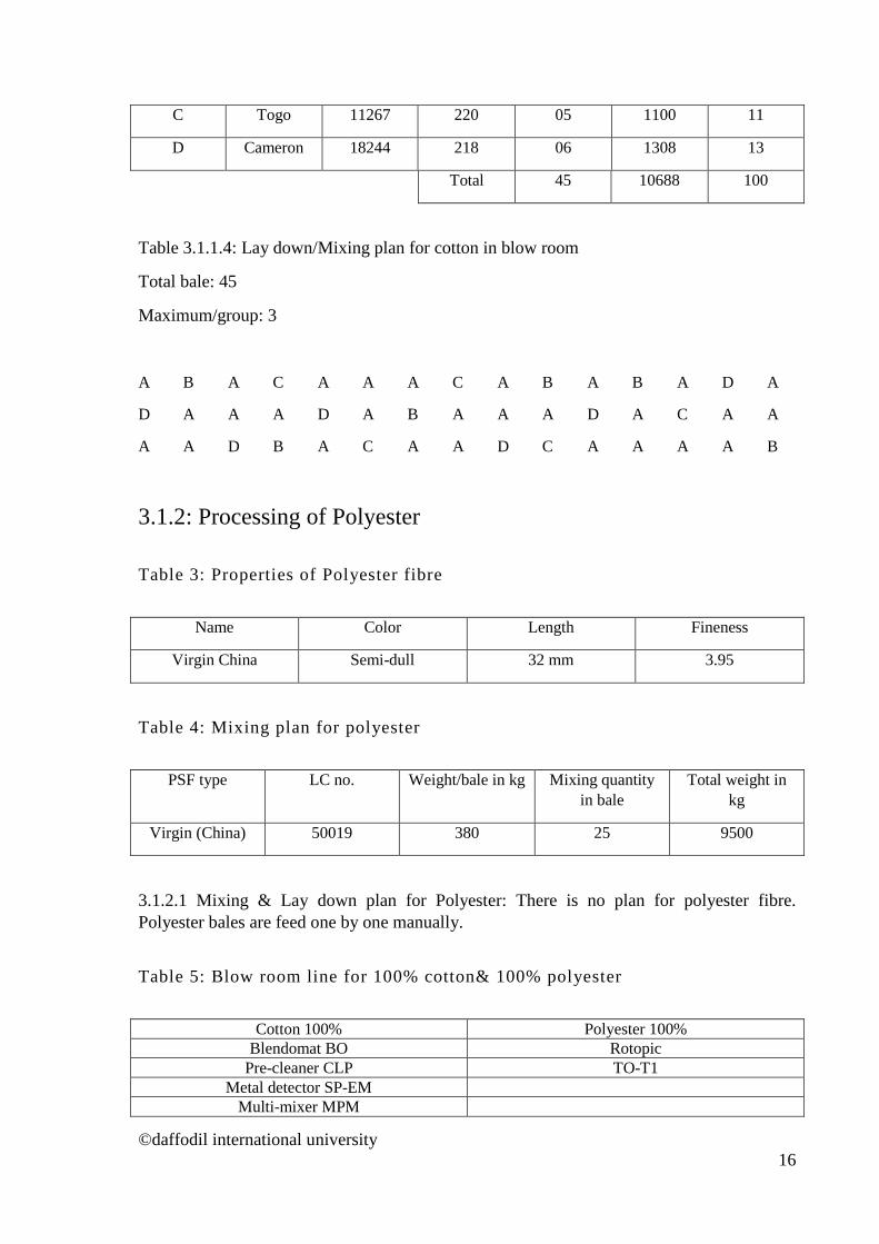
3.2 Carding
Model: Rieter C60 Card Machine Origin: Switzerland Type: Automatic Chute feed
©daffodil international university 17
3.2.1 Carding setting for 100% cotton & 100% polyester is shown in the Table 6
Table 6: Important cardsetting
Setting points 100% cotton 100% polyester Licker in - cylinder 10 12
Flat - cylinder 11.11.10.9.9 12.11.11.10.10 Cylinder - Doffer 10 8
Mote knife Front : 14 Back: 16
Front : 12 Back: 12
Stationary flat Front : 14 Back: 12
Front : 14 Back: 16
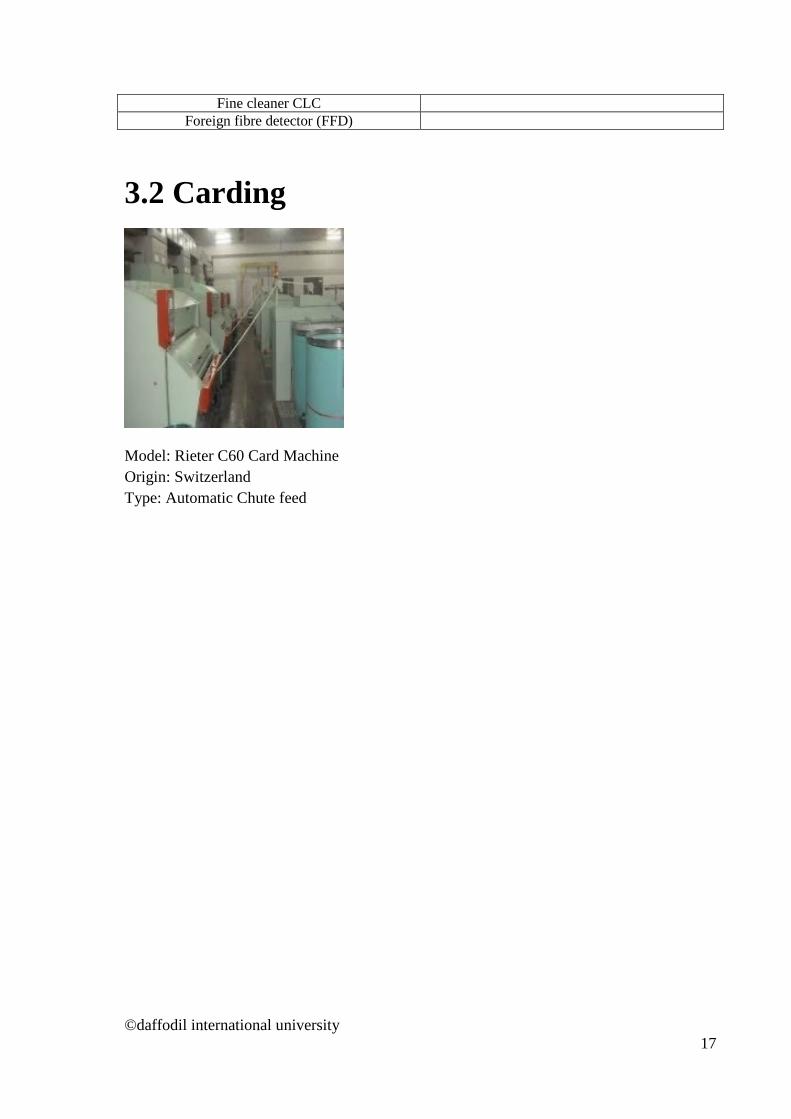
Delivery speed 150 meter/minute 160 meter/minute 3.2.1.2Quality of Card Sliver measured by Uster tester (UT 4).
In order to assess the quality of card sliver the both 100% cotton and 100% polyester were tested in Uster tester and is shown in the Table 7&Figure 1
Model: Uster tester (UT-4) Origin: Switzerland Year: 2000
©daffodil international university 18

Table 7: Uster tester report (UT-4) of Card sliver
Process U% CVm% CVm1m% Sliver weight Cotton 3.09 3.88 1.64 465 grain/6yds
Polyester 2.26 2.87 1.09 390 grain/6yds
©daffodil international university 19

Figure 1: Uster tester report (UT-4) of Card sliver
3.09
2.26
0
0.5
1
1.5
2
2.5
3
3.5
Sliver
Irreg
ular
ity/U
%
Uster report of card sliver
Cotton Polyester
©daffodil international university 20
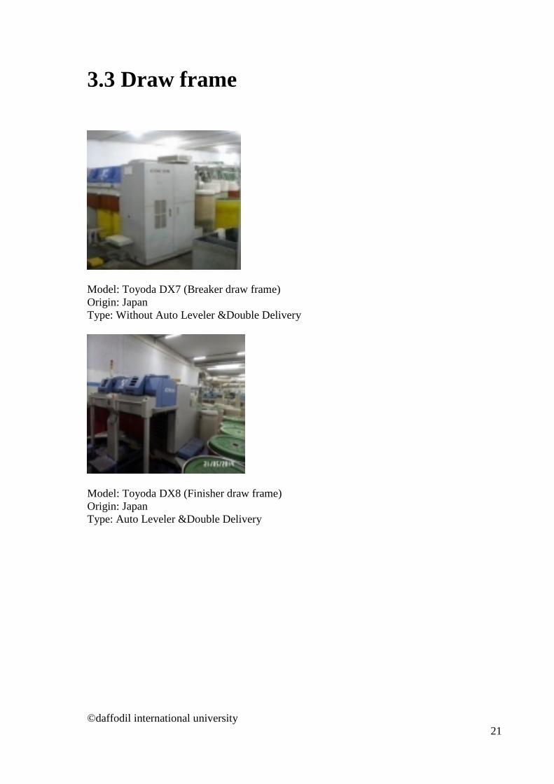
3.3 Draw frame
Model: Toyoda DX7 (Breaker draw frame) Origin: Japan Type: Without Auto Leveler &Double Delivery
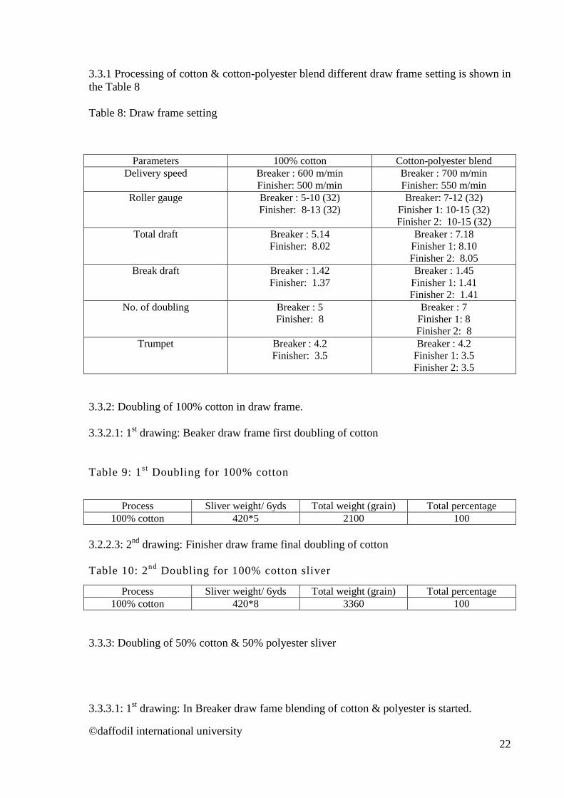
Model: Toyoda DX8 (Finisher draw frame) Origin: Japan Type: Auto Leveler &Double Delivery
©daffodil international university 21
3.3.1 Processing of cotton & cotton-polyester blend different draw frame setting is shown in the Table 8 Table 8: Draw frame setting
Parameters 100% cotton Cotton-polyester blend Delivery speed Breaker : 600 m/min
Finisher: 500 m/min Breaker : 700 m/min Finisher: 550 m/min
Roller gauge Breaker : 5-10 (32) Finisher: 8-13 (32)
Breaker: 7-12 (32) Finisher 1: 10-15 (32) Finisher 2: 10-15 (32)
Total draft Breaker : 5.14 Finisher: 8.02
Breaker : 7.18 Finisher 1: 8.10 Finisher 2: 8.05
Break draft Breaker : 1.42 Finisher: 1.37
Breaker : 1.45 Finisher 1: 1.41 Finisher 2: 1.41
No. of doubling Breaker : 5 Finisher: 8
Breaker : 7 Finisher 1: 8 Finisher 2: 8
Trumpet Breaker : 4.2 Finisher: 3.5
Breaker : 4.2 Finisher 1: 3.5 Finisher 2: 3.5
3.3.2: Doubling of 100% cotton in draw frame. 3.3.2.1: 1st drawing: Beaker draw frame first doubling of cotton Table 9: 1st Doubling for 100% cotton
Process Sliver weight/ 6yds Total weight (grain) Total percentage
100% cotton 420*5 2100 100 3.2.2.3: 2nd drawing: Finisher draw frame final doubling of cotton Table 10: 2nd Doubling for 100% cotton sliver
Process Sliver weight/ 6yds Total weight (grain) Total percentage 100% cotton 420*8 3360 100
3.3.3: Doubling of 50% cotton & 50% polyester sliver 3.3.3.1: 1st drawing: In Breaker draw fame blending of cotton & polyester is started.
©daffodil international university 22
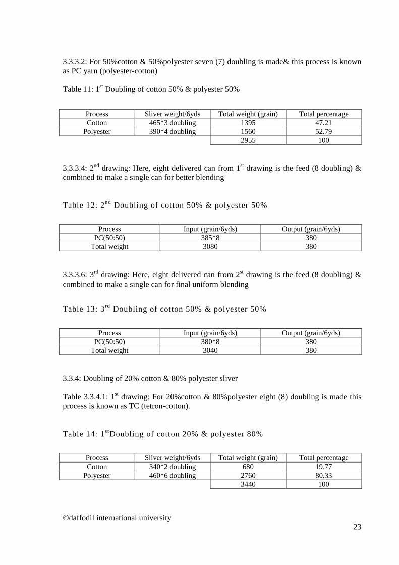
3.3.3.2: For 50%cotton & 50%polyester seven (7) doubling is made& this process is known as PC yarn (polyester-cotton) Table 11: 1st Doubling of cotton 50% & polyester 50%
Process Sliver weight/6yds Total weight (grain) Total percentage Cotton 465*3 doubling 1395 47.21
Polyester 390*4 doubling 1560 52.79 2955 100
3.3.3.4: 2nd drawing: Here, eight delivered can from 1st drawing is the feed (8 doubling) & combined to make a single can for better blending Table 12: 2nd Doubling of cotton 50% & polyester 50%
Process Input (grain/6yds) Output (grain/6yds)
PC(50:50) 385*8 380 Total weight 3080 380
3.3.3.6: 3rd drawing: Here, eight delivered can from 2st drawing is the feed (8 doubling) & combined to make a single can for final uniform blending
Table 13: 3rd Doubling of cotton 50% & polyester 50%
Process Input (grain/6yds) Output (grain/6yds)
PC(50:50) 380*8 380 Total weight 3040 380
3.3.4: Doubling of 20% cotton & 80% polyester sliver Table 3.3.4.1: 1st drawing: For 20%cotton & 80%polyester eight (8) doubling is made this process is known as TC (tetron-cotton). Table 14: 1stDoubling of cotton 20% & polyester 80%
Process Sliver weight/6yds Total weight (grain) Total percentage Cotton 340*2 doubling 680 19.77
Polyester 460*6 doubling 2760 80.33 3440 100
©daffodil international university 23
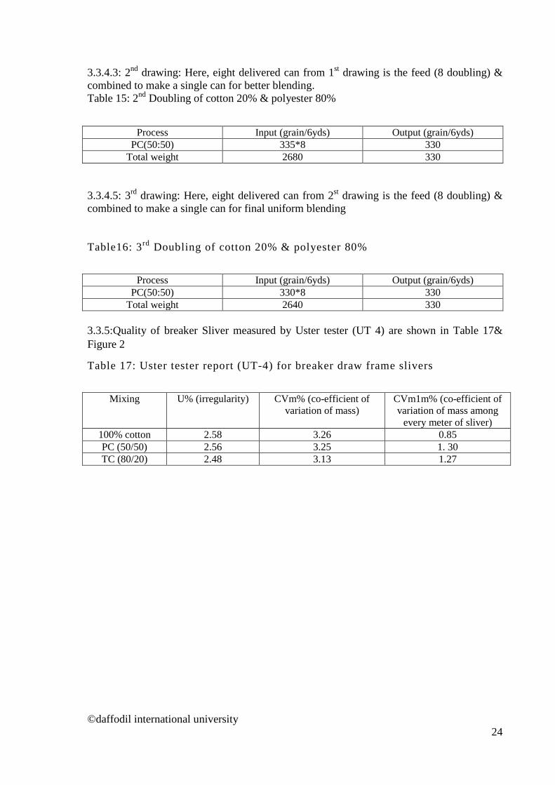
3.3.4.3: 2nd drawing: Here, eight delivered can from 1st drawing is the feed (8 doubling) & combined to make a single can for better blending. Table 15: 2nd Doubling of cotton 20% & polyester 80%
Process Input (grain/6yds) Output (grain/6yds)
PC(50:50) 335*8 330 Total weight 2680 330
3.3.4.5: 3rd drawing: Here, eight delivered can from 2st drawing is the feed (8 doubling) & combined to make a single can for final uniform blending Table16: 3rd Doubling of cotton 20% & polyester 80%
Process Input (grain/6yds) Output (grain/6yds)
PC(50:50) 330*8 330 Total weight 2640 330
3.3.5:Quality of breaker Sliver measured by Uster tester (UT 4) are shown in Table 17& Figure 2
Table 17: Uster tester report (UT-4) for breaker draw frame slivers
Mixing U% (irregularity) CVm% (co-efficient of
variation of mass) CVm1m% (co-efficient of variation of mass among
every meter of sliver) 100% cotton 2.58 3.26 0.85 PC (50/50) 2.56 3.25 1. 30 TC (80/20) 2.48 3.13 1.27
©daffodil international university 24
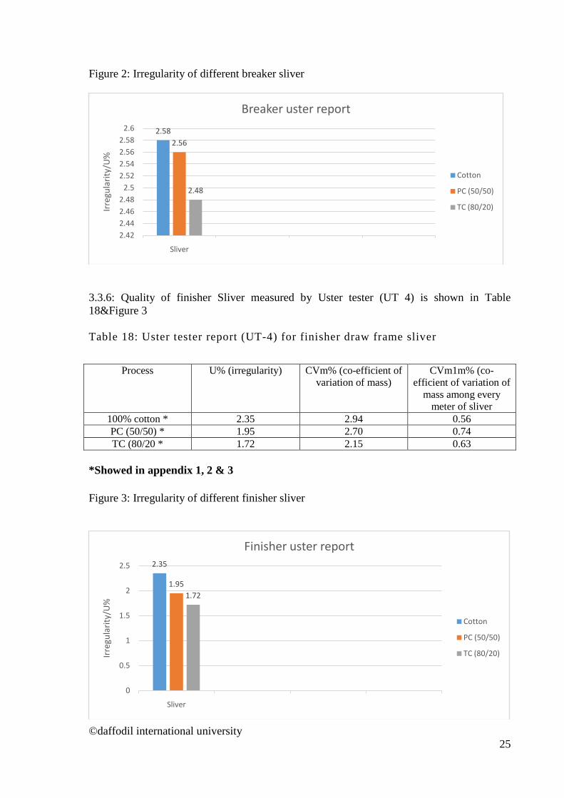
Figure 2: Irregularity of different breaker sliver
3.3.6: Quality of finisher Sliver measured by Uster tester (UT 4) is shown in Table 18&Figure 3 Table 18: Uster tester report (UT-4) for finisher draw frame sliver
Process U% (irregularity) CVm% (co-efficient of
variation of mass) CVm1m% (co-
efficient of variation of mass among every
meter of sliver 100% cotton * 2.35 2.94 0.56 PC (50/50) * 1.95 2.70 0.74 TC (80/20 * 1.72 2.15 0.63
*Showed in appendix 1, 2 & 3 Figure 3: Irregularity of different finisher sliver
2.582.56
2.48
2.422.442.462.48
2.52.522.542.562.58
2.6
Sliver
Irreg
ular
ity/U
%Breaker uster report
Cotton
PC (50/50)
TC (80/20)
2.35
1.951.72
0
0.5
1
1.5
2
2.5
Sliver
Irreg
ular
ity/U
%
Finisher uster report
Cotton
PC (50/50)
TC (80/20)
©daffodil international university 25
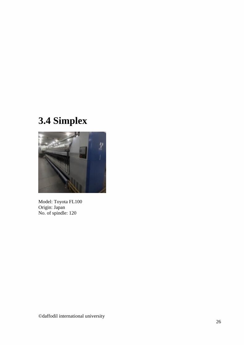
3.4 Simplex
Model: Toyota FL100 Origin: Japan No. of spindle: 120
©daffodil international university 26
3.4.1: Processing of cotton & cotton-polyester blend different simplex machine setting is shown in the Table 19
Table 19: Required simplex settings for 100% cotton & cotton-polyester blend process
Parameters 100% Cotton Cotton-Polyester blend
settings settings settings settings Flyer speed 950 950 1050 1050
Roving hank 0.90 1.10 1.10 1.30 Roving TPI 1.15 1.22 1.05 1.05 Roving TM 1.21 1.16 1.10 1.19 Total draft 7.54 8.97 8.45 9.92 Back draft 1.26 1.26 1.25 1.30
Roller gauge 37.5/49.5/48.5 (9-21-20)
37.5/49.5/48.5 (9-21-20)
37.5/49.5/48.5 (9-21-20)
37.5/49.5/48.5 (9-21-20)
Spacer Beige (5.5) Black (4.5) Beige (5.5) Black (4.5) 3.4.2: Quality of simplex roving measured by Uster tester (UT 4) is shownTable 20&Figure 4
Process U%
(irregularity) CV % mass CV% of 1 m* CV% of 3 m*
100% cotton *
4.07 5.13 1.85 1.18
50% Cotton50% polyester blend (PC)
*
3.05 3.83 1.19 0.71
20% Cotton 80%polyester (TC) *
2.99 3.57 1.60 1.10
*Shown in appendixes 4, 5 & 6.
©daffodil international university 27
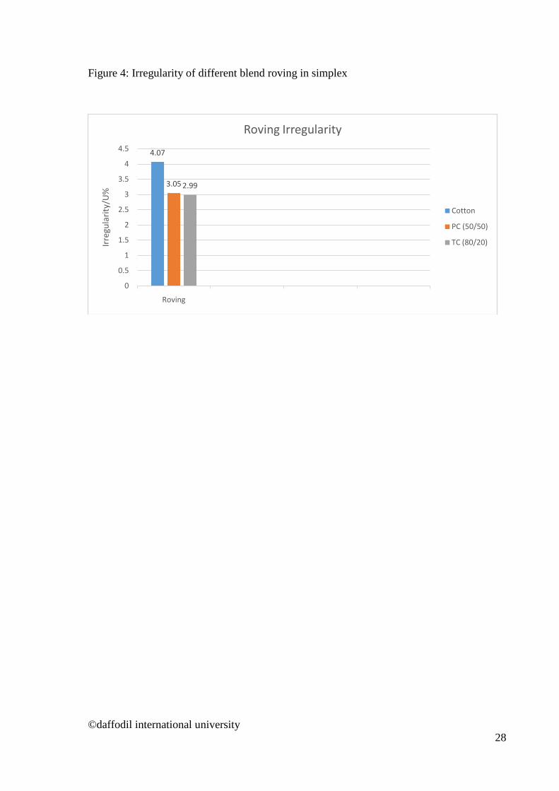
Figure 4: Irregularity of different blend roving in simplex
4.07
3.05 2.99
0
0.5
1
1.5
2
2.5
3
3.5
4
4.5
Roving
Irreg
ular
ity/U
%
Roving Irregularity
Cotton
PC (50/50)
TC (80/20)
©daffodil international university 28

3.5 Ring frame
Model: Jingwei Ring frame F1520 Origin: China No. of spindle: 960
©daffodil international university 29

3.5.1: Processing of cotton & cotton-polyester blend different ring frame setting is shown in the Table 21, Figure 5&Figure 6
Table 21: Required ring frame setting for different blend yarns
Parameters 30 KW 40 KW 100% Cotton
50/50 PC 80/20 TC 100% Cotton
50/50 PC 80/20 TC
Nominal count 30KW 30PC 30TC 40KW 40PC 40TC Actual count 30 30.20 30.10 40 40.15 40.20 Spindle speed 15000 16000 16500 16000 17000 17500
Total draft 35.87 30.20 30.40 48.14 38.70 38.90 Back draft 1.13 1.15 1.16 1.13 1.15 1.16
Roller gauge 44*54 45*65 45*65 44*54 45*65 45*65 TPI 20.67 19.20 17.45 25.6 24.71 23.05
Spacer Yellow Yellow Yellow Red Red Red Figure 5: Maximum Spindle speed utilized inring frame for different blend yarns
13500
14000
14500
15000
15500
16000
16500
17000
17500
18000
30 Ne 40 Ne
Spin
dle
spee
d
Yarn count & speed
100% cotton 50/50 PC 80/20 TC
©daffodil international university 30

Figure 6: Required Twist per inch (TPI) in ring frame for different blend yarns
3.5.2: Yarn count & Yarn strength (C.S.P) test.
Wrap reel & balance Electronic weight balance Origin: India Origin: Japan Year: 2000 Year: 2000
0
5
10
15
20
25
30
30 Ne 40 Ne
Twist
per
inch
(TPI
)
Yarn count & Twist
100% cotton 50/50 PC 80/20 TC
©daffodil international university 31
Lea strength tester Origin: India Year: 2000 3.5.2.1: Variation of yarn strength for different blends is shown in the Table 22&Figure 7. Here, Average count * Average lea strength = Count Strength Product (C.S.P)
Table 22: Yarn count & strength test for cotton
Process
Count 30 Ne Count 40 Ne Average
count Average strength
C.S.P Average count
Average strength
C.S.P
100% Cotton 30.02 92.07 2764 40.05 65.15 2609 50% cotton
50% polyester 30.10 116.20 3497 40.02 86.75 3471
20% cotton 80% polyester
30.15 129.36 3901 40.10 94.26 3780
©daffodil international university 32

Figure 7: Yarn strength variation found in ring frame
3.5.3: Yarn faults (IPI) found in ring frame for different yarns is shown in Table 3.5.3.1 &Figure 8 Table 23: Uster tester result of different blends in ring frame
Count Blend U% CVm% Thin (-
50)% Thick
(+50)% Neps
(+200) % Imperfections
IPI (thin + thick + neps)
30 KW
100%Cotton* 11.22 14.33 2.5 142.5 274 419 50/50 PC* 9.92 12.59 0 49.5 108 157.5 80/20 TC 9.70 12.12 0 42.5 99 141.5
40KW
100%Cotton 11.40 14.35 7.5 190 395.5 593 50/50 PC* 10.69 13.58 2.5 94 178.5 275 80/20 TC* 11.28 14.28 13.5 93 160 266.5
*Showed in appendix 7, 8, 9 & 10
0
500
1000
1500
2000
2500
3000
3500
4000
4500
30 Ne 40 Ne
Yarn
stre
ngth
(C.S
.P)
Yarn count & strength
100% cotton 50/50 PC 80/20 TC
©daffodil international university 33

Figure 8: Yarn faults in different blend
419
593
157.5
275
141.5
266.5
0
100
200
300
400
500
600
700
30 Ne 40 Ne
Impe
rfec
tions
(IPI
)Blends & faults
100% cotton 50/50 PC 80/20 TC
©daffodil international university 34
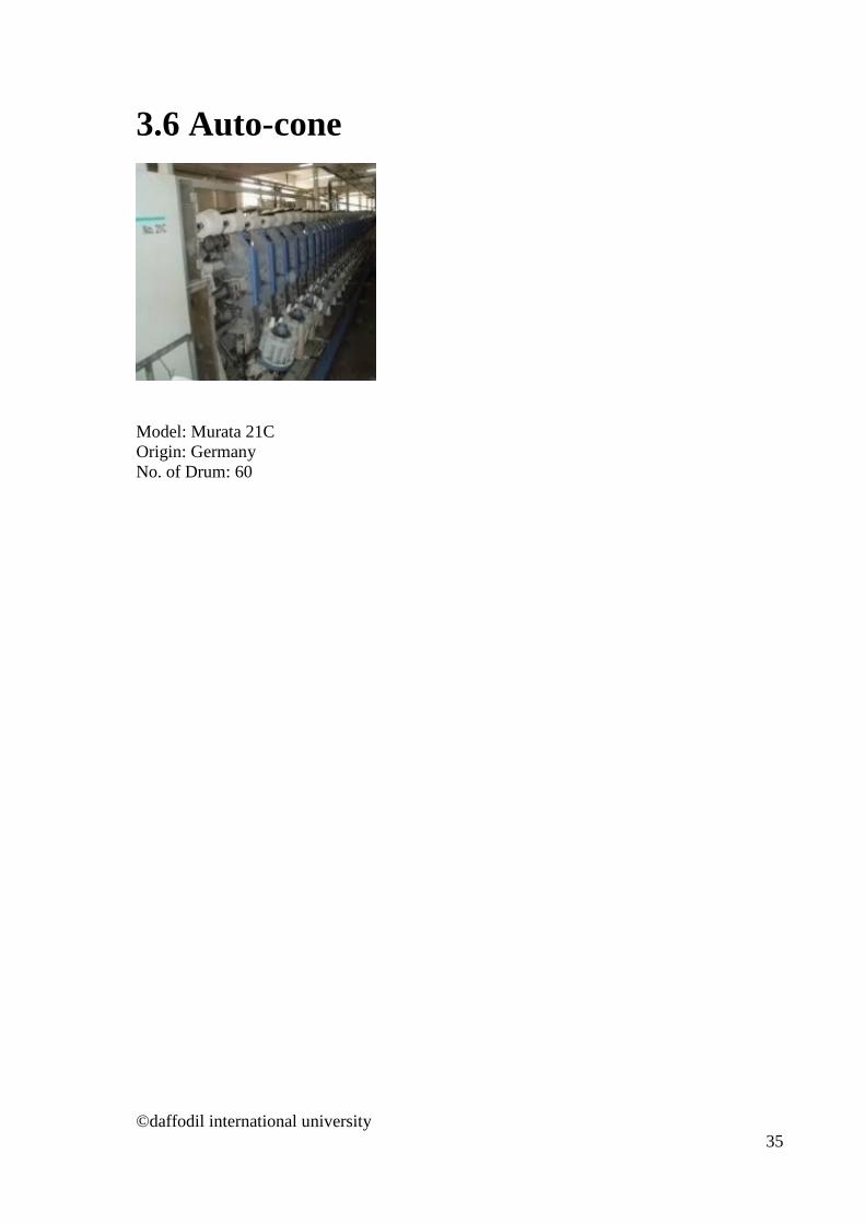
3.6 Auto-cone
Model: Murata 21C Origin: Germany No. of Drum: 60
©daffodil international university 35
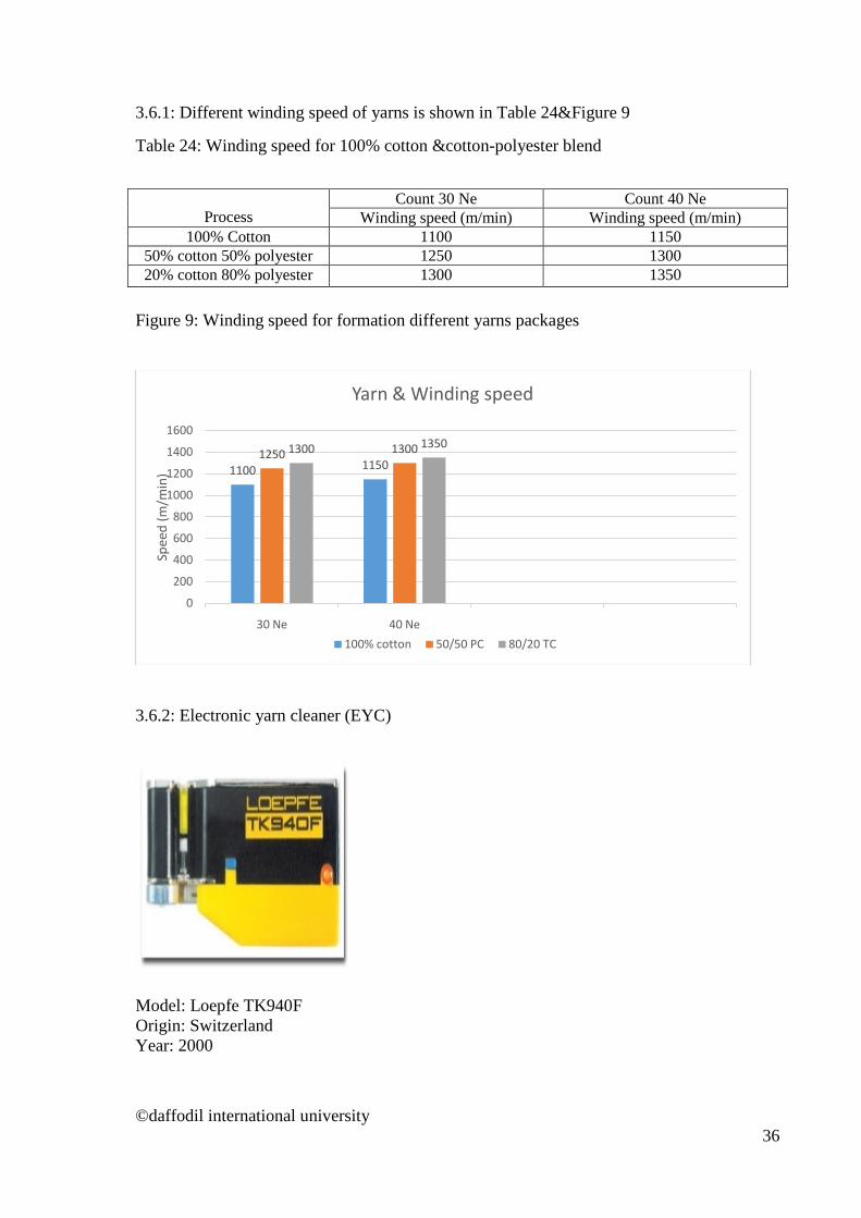
3.6.1: Different winding speed of yarns is shown in Table 24&Figure 9
Table 24: Winding speed for 100% cotton &cotton-polyester blend
Process Count 30 Ne Count 40 Ne
Winding speed (m/min) Winding speed (m/min) 100% Cotton 1100 1150
50% cotton 50% polyester 1250 1300 20% cotton 80% polyester 1300 1350
Figure 9: Winding speed for formation different yarns packages
3.6.2: Electronic yarn cleaner (EYC)
Model: Loepfe TK940F Origin: Switzerland Year: 2000
1100 11501250 13001300 1350
0
200
400
600
800
1000
1200
1400
1600
30 Ne 40 Ne
Spee
d (m
/min
)
Yarn & Winding speed
100% cotton 50/50 PC 80/20 TC
©daffodil international university 36

3.6.2.1: Electronic yarn cleaner (EYC) setting for cotton & blend process is shown in Table 25& Figure 10 Table 25: Electronic yarn cleaner (EYC) setting for different blend
Count Fault name 100% Cotton 50/50 PC 80/20 TC
Fault Diameter %) Fault length
Fault Diameter% Fault length
Fault Diameter% Fault length
All
30Ne &
40Ne
N (Neps) 4.0 5.0 6.0 S (short thick) 2.1 1.9 cm 2.20 2.1 cm 2.30 2.2 cm L (long thick) 1.25 25 cm 1.28 30 cm 1.30 30 cm
T (thin) -16 25 cm -20 30 cm -20 30 cm Cp (count plus) 7.9 10 m 11 10 m 12 10m
Cm (count minus) 6.6 11 12
Figure10: Electronic yarn cleaner (EYC) setting for different blends
42.1 1.25
-16
5
2.2 1.28
-20
6
2.3 1.3
-20
-25
-20
-15
-10
-5
0
5
10
Neps Short thick Long thick Thin
Faul
t Dia
met
er
Yarn Clearer settings
100%Cotton 50/50 PC 80/20 TC
©daffodil international university 37
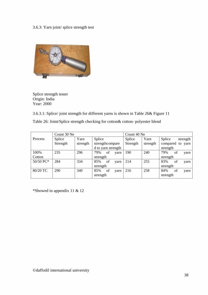
3.6.3: Yarn joint/ splice strength test
Splice strength tester Origin: India Year: 2000 3.6.3.1: Splice/ joint strength for different yarns is shown in Table 26& Figure 11
Table 26: Joint/Splice strength checking for cotton& cotton- polyester blend
Process
Count 30 Ne Count 40 Ne Splice Strength
Yarn strength
Splice strengthcompared to yarn strength
Splice Strength
Yarn strength
Splice strength compared to yarn strength
100% Cotton
235 296 79% of yarn strength
190 240 79% of yarn strength
50/50 PC* 284 334 85% of yarn strength
214 255 83% of yarn strength
80/20 TC 290 340 85% of yarn strength
216 258 84% of yarn strength
*Showed in appendix 11 & 12
©daffodil international university 38
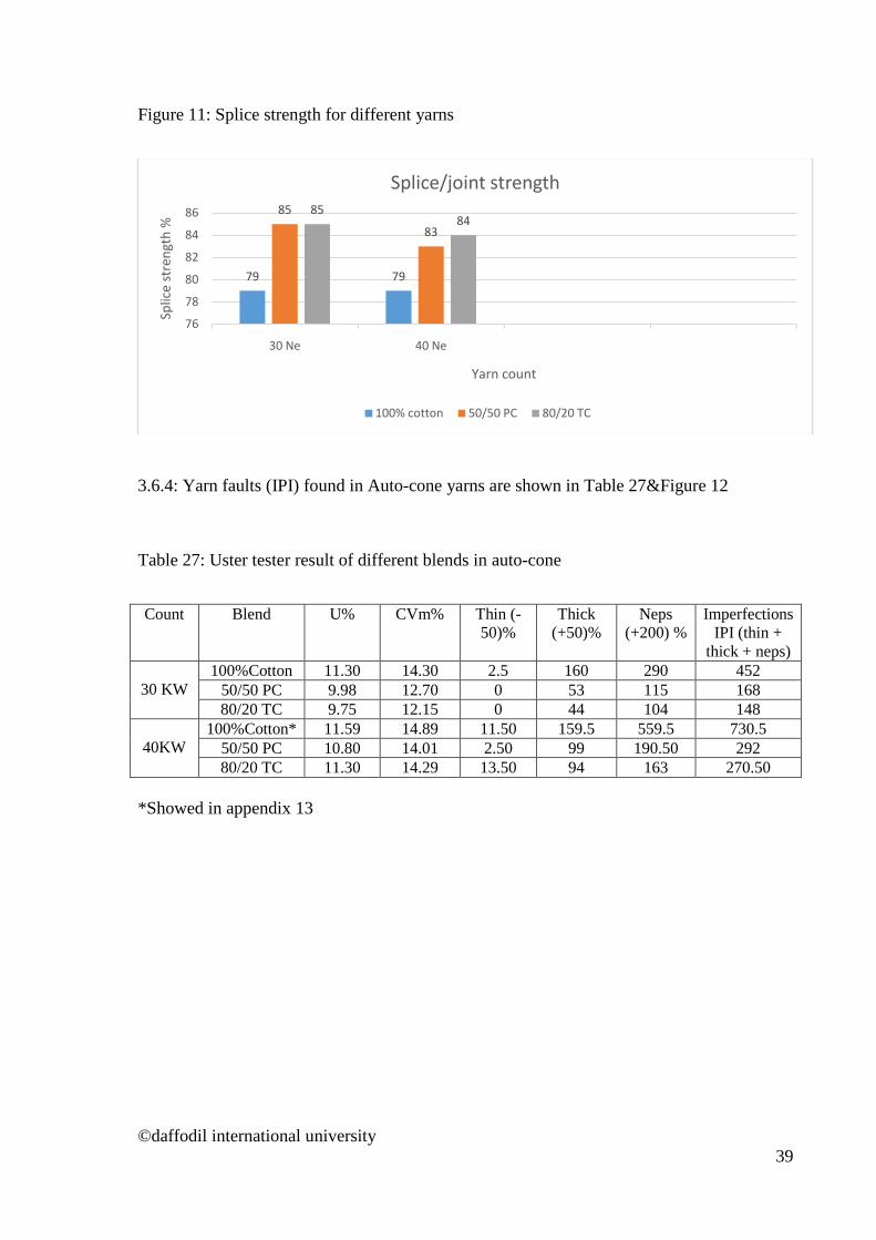
Figure 11: Splice strength for different yarns
3.6.4: Yarn faults (IPI) found in Auto-cone yarns are shown in Table 27&Figure 12
Table 27: Uster tester result of different blends in auto-cone
Count Blend U% CVm% Thin (-
50)% Thick
(+50)% Neps
(+200) % Imperfections
IPI (thin + thick + neps)
30 KW
100%Cotton 11.30 14.30 2.5 160 290 452 50/50 PC 9.98 12.70 0 53 115 168 80/20 TC 9.75 12.15 0 44 104 148
40KW
100%Cotton* 11.59 14.89 11.50 159.5 559.5 730.5 50/50 PC 10.80 14.01 2.50 99 190.50 292 80/20 TC 11.30 14.29 13.50 94 163 270.50
*Showed in appendix 13
79 79
85
83
8584
76
78
80
82
84
86
30 Ne 40 Ne
Splic
e st
reng
th %
Yarn count
Splice/joint strength
100% cotton 50/50 PC 80/20 TC
©daffodil international university 39

Figure 12: Imperfections of yarns in auto-cone
3.6.5: Yarn strength (CSP) found in auto-cone yarns is shown in Table 28&Figure 13 Table 28: Strength test (CSP) of final yarns found in auto-cone
Process
Count 30 Ne Count 40 Ne Average
count Average strength
C.S.P Average count
Average strength
C.S.P
100% Cotton 29.95 93.75 2808 40.00 66.25 2650 50/50 PC 30.08 117.68 3540 39.98 87.56 3501 80/20 TC 30.10 126.36 3930 40.10 94.96 3805
452
730.5
168
292
148
270.5
0
100
200
300
400
500
600
700
800
30 Ne 40 Ne
Impe
rfec
tions
(IPI
)
Yarn count & fault
100% cotton 50/50 PC 80/20 TC
©daffodil international university 40

Figure 13: Yarn strength variation found in auto-cone
3.7 Testing of blend ratio of yarns 3.7.1: Preparing a solution of 70% H2So4 & 30% water Solution temperature below 10 C First keep the yarn sample in pot then pour the acid-water solution into the pot. After 15-20 minutes yarn sample taken from the solution. The sample is washed with water & ironing is done to make it dry. 3.7.2: Testing of cotton & blend is shown in Table 3.7.2.2 &Table 3.7.2.3 3.7.2.1: Result of 100% cotton: Dissolved in the solution. Table 29: Result of 50% cotton & 50% polyester
Weight of sample (gram)
Weight after keeping in solution (gram)
Cotton % Polyester %
0.166 0.086 48.19 51.81 0.179 0.092 48.60 51.40 0.183 0.096 47.54 52.46
0
500
1000
1500
2000
2500
3000
3500
4000
4500
30 Ne 40 Ne
Yarn
stre
ngth
(C.S
.P)
Yarn count & strength
100% cotton 50/50 PC 80/20 TC
©daffodil international university 41
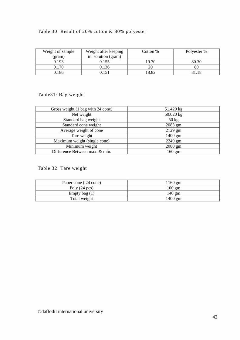
Table 30: Result of 20% cotton & 80% polyester
Weight of sample (gram)
Weight after keeping in solution (gram)
Cotton % Polyester %
0.193 0.155 19.70 80.30 0.170 0.136 20 80 0.186 0.151 18.82 81.18
Table31: Bag weight
Gross weight (1 bag with 24 cone) 51.420 kg
Net weight 50.020 kg Standard bag weight 50 kg Standard cone weight 2083 gm
Average weight of cone 2129 gm Tare weight 1400 gm
Maximum weight (single cone) 2240 gm Minimum weight 2080 gm
Difference Between max. & min. 160 gm Table 32: Tare weight
Paper cone ( 24 cone) 1160 gm
Poly (24 pcs) 100 gm Empty bag (1) 140 gm Total weight 1400 gm
©daffodil international university 42

4. Discussion of Results
4.1 Phase of Blending In this thesis blending of cotton & polyester were done in draw frame stage. Draw frame it is easier to obtain uniform blend ratio. During opening, cleaning in blow room and carding, optimum settings for each blend component (cotton & polyester) can be used for better quality of output with less damage of fibres. It is also easy to control the process in draw frame blending.
4.2Quality of blends in various stages Table7, Table17,Table18,Table20, Figure1,Figure3, Figure 4 &Figure7 shows that from carding to simplex theirregularity/U% of 100% cotton slivers & roving are higher than the polyester & its blend.
This is because Polyester is a man-made synthetic fibre. Man-made fibre’s uniformity ratio is always higher than cotton fibre because of its nature. As a result,with the increase of polyester percentage in the sliver & roving irregularity /U% decreased.Further to this the irregularity /U% was lower for TC than PC.
4.3Use of Draw Frame for 100% cotton and cotton polyester blends For 100% cotton, two draw frames (e.g. breaker & finisher) were used.But for cotton-Polyester blend three draw frames (e.g. breaker, finisher 1 & finisher 2) were used.
For uniform blending of cotton-polyester more draw frame is used than 100% cotton process.
4.4 Effect of blend ratio on production & speed of simplex/speed frame Table 19 shows that in seed frame flyer speed is higher & twist per inch is lower in cotton-polyester blend with compare to 100% cotton roving.
More flyer speed & less twist means higher production.Higher flyer speed in 100% cotton roving causes more breakage in simplex results decrease in the quality of roving. Lower twist in 100% cotton roving can causes insufficient strength of roving. These factors are mainly determined by strength, length & uniformity ratio of fibre. In polyester fibre strength, length & uniformity is better than cotton fibre. As a result, it was possible to maintain higher flyer speed and lower twist for PC & TC. Further to this the flyer speed was higher and twist was lower for TC than PC.
©daffodil international university 43

4.4 Quality of yarnsin ring frame 4.4.1 Effect of blend ratio on imperfections (IPI) of yarns
Table 23 & Figure 8 shows that the imperfections (IPI) were lower in PC & TC than 100% cotton yarns.
Imperfections (IPI) of yarns mainly depends on length, uniformity ratio, fineness & cleanliness of fibre. All these properties are higher in man-made fibre than cotton fibre. For this reason, imperfections (IPI) decreased with the increase of share or % of polyester in the yarns.
4.4.2 Effect of blend ratio on strength of yarns
Table 22 & Figure 7shows that strength is higher for PC & TC yarns than 100% cotton yarns.
Yarn strength mainly influenced by fibre strength, fibre length & fibre fineness etc. All these properties are higher in man-made polyester fibre than natural cotton fibre. As a result, yarn strength increase with the increase of polyester percentage in the yarns. Since the % of polyester is higher in TC therefore its strength was higher than that of PC yarns.
4.4.3 Effect of blend ratio on production & speed of ring frame.
Table 21, Figure 5 & Figure 6 shows that in ring frame spindle speed is higher & twist per inch is lower in cotton-polyester blend yarns with compare to 100% cotton yarns.
More spindle speed & less twist means higher production. Higher spindle speed in 100% cotton roving causes more breakage in ring frame results decrease in the quality of yarn. Lower twist in 100% cotton yarn can causes insufficient strength of yarn. These factors are mainly determined by strength, length & uniformity ratio of fibre. In polyester fibre strength, length & uniformity is better than cotton fibre. As a result, it was possible to maintain higher spindle speed and lower twist for PC & TC. Further to this the spindle speed was higher and twist was lower for TC than PC.
©daffodil international university 44
5. CONCLUSION The works reported in thesis was a comparative study between the properties of 100% cotton yarns with cotton polyester blend. It was observed that as the percentage of polyester increasesthe U% i.e. the irregularity in the sliver & roving decreases.For uniform blending of cotton-polyester more draw frame was required than that was required for 100% cotton process. In the roving frame it was possible to maintain higher flyer speed and lower twist for PC & TC. Between TC & PC the flyer speed was higher and twist was lower for TC than PC.It was observed that iimperfections (IPI) decreased with the increase of share or % of polyester in the yarns.The yarn strength increases with the increase of polyester percentage in the yarns. Since the % of polyester is higher in TC therefore its strength was higher than that of PC yarns.It was possible to maintain higher spindle speed and lower twist for PC & TC. Further to this the spindle speed was higher and twist was lower for TC than PC.
©daffodil international university 45

6. REFERENCES
1. W.C. Harris, Some aspects of preblending cotton, 1962. 2. J.B. Speakman, Fibre Blends, 49, p.580 3. S.A.G. Caldweel, Modern Fibre Blending Practice, 1961 4. D.E. Howe, Massive Blending as a means Levelling Out Cotton’s Variables, 1959. 5. Caldwell, p. 52 6. G.V. Lund, Fibre Blending, 1954 7. D.R. Cox, Some Statistical Aspects of Mixing & Blending, 1954 8. J.E. Ford, Segregation of component fibres in Blended yarn, 1958 9. J.F. Bogdan, An Exploration of Roller Drafting, 1962. 10. The Technology of Short-staple spinning by W. Klein 11. Spun Yarn Technology volume (1& 2) by A. Venkatasubramani 12. Essential practical cotton spinning by T.K Pattabiram 13. Elements of carding and drawing by Prof. R.A. Khare 14. Elements of raw cotton and blow room by Dr. A. R. Khare 15. Spun Yarn Technology volume (1& 2) by A. Venkatasubramani 16. Essential practical cotton spinning by T.K Pattabiram
©daffodil international university 46
Related Documents