[Patil, 3(9): September, 2014] ISSN: 2277-9655 Scientific Journal Impact Factor: 3.449 (ISRA), Impact Factor: 1.852 http: // www.ijesrt.com (C)International Journal of Engineering Sciences & Research Technology [503] IJESRT INTERNATIONAL JOURNAL OF ENGINEERING SCIENCES & RESEARCH TECHNOLOGY Comparative Analysis of Various Condenser in Vapour Compression Refrigeration System Patil Deepak P. *, Prof. Bhangale J.H., Prof. Palande D.D. * PG Student,M.E (Heat Power), Department of Mechanical Engineering, MCERC Eklahare Nasik, India [email protected] Head of Department, Department of Mechanical Engineering, MCERC Eklahare Nasik, India Associate Professor, Department of Mechanical Engineering, MCERC Eklahare Nasik, India Abstract The present work is to analyze performance of refrigeration system on three condensers viz. micro-channel, round tube and coil tube using R134a and R290 refrigerants. These three condensers are kept in parallel with other components of refrigerating unit while construction.The performance of refrigeration system is checked for each condenser at various cooling loads in the range from 175 W to 288 W.The performance of the condenser is measured for whole refrigeration unit in terms of coefficient of performance, efficiency of the system, heat rejection ratio, heat rejected from condenserand heat transfer coefficient. The experimental data of heat transfer coefficient is validated with existing correlation.The result shows that for both refrigerants R134a and R290, coefficient of performance increases with increase in heating load. From the analysis of three condensers, coefficient of performance of refrigeration system using microchannel condenser is more compared to round tube and coil tube condenser. The coefficient of performance of the system with the microchannel condenser is found 15.3% higher than that with the round tube condenser and 8% higher than that with the coil tube condenser. AlsoR134a gives better cooling effect than the R290 for all operating condition. Keywords: Microchannel, refrigerant, C.O.P., cooling load. Introduction Heat exchangers with multi-ported microchannel tubes are already used in mobile air- conditioning systems due to their compactness and high performance. For better understanding of the physical phenomena in microchannel tubes, the characteristics of heat transfer, pressure drop, and flow patterns have been studied by many researchers. The ability of micro channels to provide high surface area-to volume ratios, high heat transfer coefficients, high efficiencies and system compactness are among the major advantages of microchannel for use in a diverse range of industries. Condensation heat transfer in micro-channels and mini-channels is naturally of great practical importance in development of next generation ultra-compact and high performance two-phase flow thermal systems. But compared to the evaporation phenomenon, condensation in microchannel has been the subject of fewer studies. It can be argued that these two phenomena are essentially similar, and this may be true to some extent. The main aim of the current study was to characterize the condensation heat transfer performance of two selected refrigerants R134a (Tetrafluroethane) and R290 (Propane) in a single square micro-channel condenser, round tube condenser and coil tube condenser. The condenser heat exchanger plays a significant role in the structure and operation of the heat pump as it affects the system’s coefficient of performance (COP). Two heat exchangers were used as condensers in the same air-conditioning system, one with round tubes and the other with flat microchannel tubes in a parallel-flow arrangement. The differences were recorded and are explained herein. This paper presents the difference measured in the performance for three condensers only as well as the effects on the system. The microchannel heat exchanger was made to have nearly an identical face area, depth and consequently volume, plus the same fin density as the baseline, round-tube heat exchanger with plate fins. The baseline condenser along with all other elements of the system was part of the very generously sized, off- the-shelf, air-conditioning system manufactured by one of the market and technology leaders.

Welcome message from author
This document is posted to help you gain knowledge. Please leave a comment to let me know what you think about it! Share it to your friends and learn new things together.
Transcript

[Patil, 3(9): September, 2014] ISSN: 2277-9655
Scientific Journal Impact Factor: 3.449
(ISRA), Impact Factor: 1.852
http: // www.ijesrt.com (C)International Journal of Engineering Sciences & Research Technology
[503]
IJESRT INTERNATIONAL JOURNAL OF ENGINEERING SCIENCES & RESEARCH
TECHNOLOGY
Comparative Analysis of Various Condenser in Vapour Compression Refrigeration System Patil Deepak P. *, Prof. Bhangale J.H., Prof. Palande D.D.
* PG Student,M.E (Heat Power), Department of Mechanical Engineering, MCERC Eklahare Nasik, India
Head of Department, Department of Mechanical Engineering, MCERC Eklahare Nasik, India
Associate Professor, Department of Mechanical Engineering, MCERC Eklahare Nasik, India
Abstract The present work is to analyze performance of refrigeration system on three condensers viz. micro-channel,
round tube and coil tube using R134a and R290 refrigerants. These three condensers are kept in parallel with other
components of refrigerating unit while construction.The performance of refrigeration system is checked for each
condenser at various cooling loads in the range from 175 W to 288 W.The performance of the condenser is
measured for whole refrigeration unit in terms of coefficient of performance, efficiency of the system, heat rejection
ratio, heat rejected from condenserand heat transfer coefficient.
The experimental data of heat transfer coefficient is validated with existing correlation.The result shows
that for both refrigerants R134a and R290, coefficient of performance increases with increase in heating load. From
the analysis of three condensers, coefficient of performance of refrigeration system using microchannel condenser is
more compared to round tube and coil tube condenser. The coefficient of performance of the system with the
microchannel condenser is found 15.3% higher than that with the round tube condenser and 8% higher than that with
the coil tube condenser. AlsoR134a gives better cooling effect than the R290 for all operating condition.
Keywords: Microchannel, refrigerant, C.O.P., cooling load.
Introduction Heat exchangers with multi-ported
microchannel tubes are already used in mobile air-
conditioning systems due to their compactness and
high performance. For better understanding of the
physical phenomena in microchannel tubes, the
characteristics of heat transfer, pressure drop, and
flow patterns have been studied by many researchers.
The ability of micro channels to provide high surface
area-to volume ratios, high heat transfer coefficients,
high efficiencies and system compactness are among
the major advantages of microchannel for use in a
diverse range of industries. Condensation heat
transfer in micro-channels and mini-channels is
naturally of great practical importance in
development of next generation ultra-compact and
high performance two-phase flow thermal systems.
But compared to the evaporation phenomenon,
condensation in microchannel has been the subject of
fewer studies. It can be argued that these two
phenomena are essentially similar, and this may be
true to some extent. The main aim of the current
study was to characterize the condensation heat
transfer performance of two selected refrigerants
R134a (Tetrafluroethane) and R290 (Propane) in a
single square micro-channel condenser, round tube
condenser and coil tube condenser. The condenser
heat exchanger plays a significant role in the
structure and operation of the heat pump as it affects
the system’s coefficient of performance (COP). Two
heat exchangers were used as condensers in the same
air-conditioning system, one with round tubes and the
other with flat microchannel tubes in a parallel-flow
arrangement. The differences were recorded and are
explained herein. This paper presents the difference
measured in the performance for three condensers
only as well as the effects on the system. The
microchannel heat exchanger was made to have
nearly an identical face area, depth and consequently
volume, plus the same fin density as the baseline,
round-tube heat exchanger with plate fins. The
baseline condenser along with all other elements of
the system was part of the very generously sized, off-
the-shelf, air-conditioning system manufactured by
one of the market and technology leaders.

[Patil, 3(9): September, 2014] ISSN: 2277-9655
Scientific Journal Impact Factor: 3.449
(ISRA), Impact Factor: 1.852
http: // www.ijesrt.com (C)International Journal of Engineering Sciences & Research Technology
[504]
The literature review is carried out in order to see the
present research in this area which is elaborated
under the present status. Many researchers have
attempted experimental and theoretical work on
micro channel condenser some of this work is
focused on the use of micro channel condensers in
refrigeration System exchangers.
D. A. Luhrs and W. E. Dunn (1994) [1], Presented
Design and Construction of a Microchannel
Condenser Tube Experimental Facility. A test facility
was built for the purpose of performing heat transfer
studies on microchannel heat exchangers. The studies
will involve condensation of refrigerant 134a inside
the enhanced tubes,' although no condensation results
are presented in this document. The design and
construction of the experimental facility is detailed
with a description of each component and its function
in the stand. The operation of the facility was verified
using an energy balance analysis and the results are
presented. The refrigerant and air side heat transfers
agree within ±3% at high air flow rates but fall out of
this error bound at lower flow rates. Also, a
discussion of the method for determining the
refrigerant and air side resistances for the tube is
given along with the theory for future correlation
development. Finally, future modifications to the
stand are suggested in order to correct any problems
with it, improving the ability of the stand to produce
accurate, reliable heat transfer performance data.
Riehl et al. (1998) [2], reviewed single-phase and
two-phase flow heat transfer coefficients of
experimental data obtained for micro channels and
compared them to the available analytical models.
The comparisons showed large discrepancies. The
models they examined were not able to predict the
experimental data accurately. Furthermore,
correlations of micro-channel convective flow also
showed wide discrepancies. Later Riehl and
Ochterbeck presented experimental results of
condensation using methanol as the working fluid.
The experiments were conducted for two different
saturation temperatures, range of heat dissipation rate
from 20 to 350W and four microchannel condensers
with channel diameters between 0.5 and 1.5 mm. All
the channels had aspect ratios of 1. Their results
showed high heat transfer coefficients with Nusselt
numbers ranging from 15 to 600. They also obtained
a Nusselt number correlation which was able to
predict 95% of the data within 25% error band.
Yin et al. (2001) [3], developed a CO2 microchannel
gas cooler model. In their model, each pass was
separated into 10 equal-length element. The model
predicted the gas cooler capacity with good accuracy.
A serpentine microchannel gas cooler model based
on the microchannel gas cooler model presented by
Yin et al. (2001) was used to simulate the serpentine
gas cooler in their investigation. Tubes in each slab
were divided into 10 elements. Thermal conductivity
of the serpentine microchannel gas cooler was not
considered in their model. The uniform air flow
assumption was used in the serpentine gas cooler
model.
Cavallini et al. (2002) investigated [4] ,condensation
of R123a, R125, R410a, R32, R236ea and R22 inside
a round tube with 8 mm inner diameter while varying
the mass flux from 100 to750 kg m-2 s-1. The study
intended to improve Friedel’s correlation (1979) in
the annular regime. They also used the dimensionless
vapor velocity to distinguish between the different
flow regimes that exist in condensation. Then new
constants were fitted to the Friedel’s correlation from
the study of the annular regime, and Due to the
insignificant effect of gravitational forces in the
annular flow regime, the Froude number was not
accounted for in the two-phase multiplier correlation.
However, these predictions cannot be applied to flow
transitions.
Kim et al. (2003) [5], studied condensation in flat
aluminum multi-channel tubes using R410A and
R22. The tubes had two internal geometries: one with
a smooth inner surface (Dh = 1.41 mm), the other
with a micro-finned inner surface (Dh = 1.56 mm).
Their results showed that for the smooth tube, the
heat transfer coefficient of R410A was slightly larger
than that of R22. For the micro-finned tube, however,
the trend was reversed. They also compared their data
with Webb’s (1999), Koyama et al.’s (2003a, b),
Akers et al.’s (1959) and Shah’s (1979) correlations
and concluded that for the smooth tube, Webb’s
correlation predicted the data reasonably well. For
the micro-finned tube, they modified Yang and
Webb’s (1997) model to correlate with their data.
The modified model predicted the data within 30%.
El Hajal et al. and Thome et al. (2003) [6], studied
condensation of 15 different fluids amongst which
were pure refrigerants and refrigerant blends. They
used the studies of Kattan et al. (1998a, 1998b,
1998c) of evaporating refrigerants to develop a flow
regime map and a heat transfer model. In this study
they observed the following regimes: bubbly flow,
intermittent, annular, stratified wavy, fully stratified
and mist. However, the model did not include the
bubbly flow regime. They suggested that heat
transfer occurred due to two types of mechanisms:
[Patil, 3(9): September, 2014] ISSN: 2277-9655
Scientific Journal Impact Factor: 3.449
(ISRA), Impact Factor: 1.852
http: // www.ijesrt.com (C)International Journal of Engineering Sciences & Research Technology
[505]
film and convective condensation. The regimes that
contributed to convective condensation were annular,
mist and intermittent flows, whereas stratified-wavy
and stratified flows were governed by both
mechanisms. The developed correlation of heat
transfer coefficient was governed by the interfacial
friction factor, Prandtl number and Reynolds number.
Baird et al. (2003) [7], experimentally investigated
local heat transfer coefficient of condensation for
R123 and of R11 inside 0.92 mm and 1.95 tube
diameters, a range of mass fluxes 70-600 kgm-2 s-1,
heat fluxes 15-110 kWm-2, and pressures 120-410
KPa. Their data showed a strong influence of mass
flux and local quality on the heat transfer coefficient,
with a weaker influence of system pressure. Then
they developed a model that agreed with their
experimental data more than other models by using a
simple shear driven annular flow model to predict the
condensation heat transfer coefficient.
Bandhauer et al. (2006) [8], implemented a thermal
amplification technique for the accurate measurement
of small heat duties over small refrigerant quality
increments. They reported local heat transfer rates
within 10% for 0.506, 0.761 and 1.520 mm circular
multichannel tubes with R134a as the working fluid.
Measurements were conducted over mass flux range
150-750 kg m2 s1 and refrigerant quality range about
0.15-0.85. In general, the data indicated an
approximately linear trend between heat transfer
coefficient and local quality over the range of
qualities and mass fluxes measured. However, the
proper distinction between heat transfer coefficients
at different mass fluxes was difficult since the
differences fell within the measurement uncertainty.
Also there was no information about the possible
effect of flow mal distribution among parallel tubes
on measured parameters. The authors also developed
a model for calculation of heat transfer coefficient
that used their pressure drop model to compute the
interfacial shear stress and the friction velocity. The
resulting model predicts 86% of the data within 20%
and also captured correctly the trends exhibited by
the data.
Pega Hrnjak, 1, Andy D. Litch [9], Reported
Microchannel heat exchangers for charge
minimization in air-cooled ammonia condensers and
chillers. They presented experimental results from a
prototype ammonia chiller with an air-cooled
condenser and a plate evaporator. The main
objectives were charge reduction and compactness of
the system. The charge is reduced to 20 g/kW (2.5
oz/Ton). This is lower than any currently available
air-cooled ammonia chiller on the market. The major
contribution comes from use of microchannel
aluminum tubes. Two aluminum condensers were
evaluated in the chiller: one with a parallel tube
arrangement between headers and ‘‘microchannel’’
tubes (hydraulic diameter Dh = 0.7 mm), and the
other with a single serpentine ‘‘macrochannel’’ tube
(Dh = 4.06 mm). The performances of the chiller and
condensers are compared based on various criteria to
other available ammonia chillers. This prototype was
made and examined in the Air Conditioning and
Refrigeration Center in 1998, at the University of
Illinois at Urbana-Champaign.
Qian Sub, Guang Xu Yua, Hua Sheng Wanga [2009]
[10], reported short communication on Microchannel
condensation: Correlations and theory Attention is
drawn, to the fact that, while four different
correlations for condensation in Micro channels are
in fair agreement for the case of R134a (on which the
empirical constants in the correlations are
predominately based) they differ markedly when
applied to other fluids such as ammonia. A wholly
theoretical model is compared with the correlations
for both R134a and ammonia.
Son and Lee (2009) [11], carried out experiments on
condensation heat transfer of R22, R134a and R410A
in single-channels with 1.77, 3.36 and 5.35 mm
diameters, mass flux of 200-400 kgm-2 s-1 and
saturation temperature of 40 °C. They observed that
annular flow is almost the dominant flow regime for
condensation in small diameter tubes and reported an
earlier transition into the annular flow in their
microchannel tubes. Also they concluded that the
majority of the existing correlations failed to predict
their condensation data accurately, and they proposed
their own correlation. Some researchers (Kim et al.
(2003a, b) and Wang et al. (2002)) suggested that the
condensation phenomena in minichannels may be
different from those in macro-channels.
Liang-Liang Shaoa, Liang Yanga,b, Chun-Lu
Zhangb,, Bo Gua (2009)[12] , presented Numerical
modeling of serpentine microchannel condensers
Microchannel (or minichannel) heat exchangers are
drawing more attention because of the potential cost
reduction and the lower refrigerant charge.
Serpentine microchannel heat exchangers are even
more compact because of the minimized headers.
Using the serpentine microchannel condenser, some
thermodynamically good but flammable refrigerants
like R-290 (Propane) can be extended to more
applications. To well size the serpentine
microchannel condensers, a distributed-parameter
[Patil, 3(9): September, 2014] ISSN: 2277-9655
Scientific Journal Impact Factor: 3.449
(ISRA), Impact Factor: 1.852
http: // www.ijesrt.com (C)International Journal of Engineering Sciences & Research Technology
[506]
model has been developed in this paper. Model
validation shows good agreement with the
experimental data. The predictions on the heating
capacity and the pressure drop fall into 10% error
band. Further analysis shows the impact of the pass
number and the airside maldistribution on the
condenser performance.
Akhil Agarwal , Todd M. Bandhauer , Srinivas
Garimella (2010)[13] , Reported measurement and
modeling of condensation heat transfer in non-
circular microchannel Heat transfer coefficients in six
non-circular horizontal microchannel (0.424 < Dh <
0.839 mm) of different shapes during condensation of
refrigerant R134a over the mass flux range 150 < G <
750 kg m2 s1 were measured in this study. The
channels included barrel-shaped, N-shaped,
rectangular, square, and triangular extruded tubes,
and a channel with a W-shaped corrugated insert that
yielded triangular microchannel. The thermal
amplification technique developed and reported in
earlier work by the authors is used to measure the
heat transfer coefficients across the vapor-liquid
dome in small increments of vapor quality. Results
from previous work by the authors on condensation
flow mechanisms in microchannel geometries were
used to interpret the results based on the applicable
flow regimes. The effect of tube shape was also
considered in deciding the applicable flow regime. A
modified version of the annular-flow-based heat
transfer model proposed recently by the authors for
circular microchannel, with the required shear stress
being calculated from a non-circular microchannel
pressure drop model also reported earlier was found
to best correlate the present data for square,
rectangular and barrel shaped microchannel. For the
other microchannel shapes with sharp acute-angle
corners, a mist-flow-based model from the literature
on larger tubes was found to suffice for the prediction
of the heat transfer data. These models predict the
data significantly better than the other available
correlations in the literature.
J.R. Garcı´a-Cascales, F. Vera-Garcı´a, J.
Gonza´lvez-Macia (2010) [14], Presented Compact
heat exchangers modeling: Condensation a model for
the analysis of compact heat exchangers working as
either evaporators or condensers is presented. This
paper will focus exclusively on condensation
modeling. The model is based on cell discretization
of the heat exchanger in such a way that cells are
analyzed following the path imposed by the
refrigerant flowing through the tubes. It has been
implemented in a robust code developed for assisting
with the design of compact heat exchangers and
refrigeration systems. These heat exchangers consist
of serpentine fins that are brazed to multi-port tubes
with internal microchannel. This paper also
investigates a number of correlations used for the
calculation of the refrigerant side heat transfer
coefficient. They are evaluated comparing the
predicted data with the experimental data. The
working fluids used in the experiments are R134a
and R410A, and the secondary fluid is air. The
experimental facility is briefly described and some
conclusions are finally drawn.
ZHANG Huiyong, LI Junming , LI Hongqi (2010)
[15] , Presented Numerical Simulations of a Micro-
Channel Wall-Tube Condenser for Domestic
Refrigerators In recent years, microchannel heat
exchangers have begun to be used in refrigeration
and air conditioning systems. This paper introduces a
microchannel condenser for domestic refrigerators
with a theoretical model to evaluate its performance.
The model was used to obtain the optimal design
parameters for different numbers of tubes and tube
lengths. The results show that the needed tube height
of the downward section decreases with the number
of tubes and the tube diameter. Compared with the
original condenser, the present optimal design
parameters can reduce the total metal mass by 48.6%
for the two wall two side design and by 26% for the
two wall one side design. Thus, the present condenser
is much better than the condensers usually used in
actual domestic refrigerators.
Gunda Mader, Georg P.F. Fosel, Lars F.S.
Larsen(2013) [16] Presented Comparison of the
transient behavior of microchannel and fin-and-tube
evaporators The development of control algorithms
for refrigeration systems requires models capable of
simulating transient behavior with sensible
computational time and effort. The most pronounced
dynamics in these systems are found in the condenser
and the evaporator, especially the transient behavior
of the evaporator is of great importance when
designing and tuning controllers for refrigeration
systems. Various so called moving boundary models
were developed for capturing these dynamics and
showed to cover the important characteristics. A
factor that has significant influence on the time
constant and nonlinear behavior of a system is the
amount of refrigerant charge in the evaporator which
is considerably reduced when microchannel heat
exchangers are utilized. Here a moving boundary
model is used and adapted to simulate and compare
the transient behavior of a microchannel evaporator
with a fin-and-tube evaporator for a residential air-

[Patil, 3(9): September, 2014] ISSN: 2277-9655
Scientific Journal Impact Factor: 3.449
(ISRA), Impact Factor: 1.852
http: // www.ijesrt.com (C)International Journal of Engineering Sciences & Research Technology
[507]
conditioning system. The results are validated
experimentally at a test rig.
G.B. Ribeiro, J.R. Barbosa Jr. A.T. Prata(2013) [17]
Presented Performance of microchannel condensers
with metal foams on the air-side: Application in
small-scale refrigeration systems the thermal-
hydraulic performance of microchannel condensers
with open-cell metal foams to enhance the air-side
heat transfer is investigated in this paper. Three
different copper metal foam structures with distinct
pore densities (10 and 20 PPI) and porosities (0.893
and 0.947) were tested. A conventional condenser
surface, with copper plain fins, was also tested for
performance comparison purposes. The experimental
apparatus consisted of a closed-loop wind tunnel
calorimeter and a refrigerant loop, which allowed the
specification of the mass flow rate and
thermodynamic state of R-600a at the condenser
inlet. The experiments were performed at a
condensing temperature of 45 °C. The air-side flow
rate ranged from 1.4 – 10.3 to 3.3 – 10.3 m3/s (giving
face velocities in the range of 2.1e4.9 m/s). The heat
transfer rate, the overall thermal conductance, the
Colburn j-factor, the friction factor and the pumping
power were calculated as part of the analysis.
Present Status of microchannel condenser Presently microchannel condensers are used
in electronics and automobile air conditioning.
Extensive study of Measurement and modeling of
condensation heat transfer in non circular
microchannel has been carried out. Various
correlations And Theories for condensation in
microchannel are developed also experimental results
for ammonia chillers with air cooled condensers and
plate evaporators are presented which reduces charge
and gives compactness to the system. The thermal
hydraulic performance of microchannel condensers
with open cell metal foam to enhance the air side heat
transfer is investigated and heat transfer rate, the
overall thermal conductance, pumping power is
calculated for the same.
Objective of the study Heat exchangers with multi-ported
microchannel tubes are already used in mobile air-
conditioning systems due to their compactness and
high performance. To study the measurements and
modeling of condensation heat transfer in
microchannel. Also to apply various correlations and
theories of condensations for the given setup.
Experimentation
A liquid boils and condenses – the change
between the liquid and gaseous states at a
temperature which depends on its pressure, within the
limits of its freezing point and critical temperature. In
boiling it must obtain the latent heat of evaporation
and in condensing the latent heat must be given up
again. The basic refrigeration cycle makes use of the
boiling and condensing of a working fluid at different
temperatures and, therefore, at different pressures.
Heat is put into the fluid at the lower temperature and
pressure and provides the latent heat to make it boil
and change to a vapour. This vapour is then
mechanically compressed to a higher pressure and a
corresponding saturation temperature at which its
latent heat can be rejected so that it changes back to a
liquid.
Microchannel condenser:-Microchannel heat
exchangers have begun to be used in refrigeration
and air conditioning systems mainly consists of
microchannel tubes, louvered fins, header tubes,
baffles, receiver/dryer bottle, and inlet/outlet fittings.
Parallel flow (PF) condenser, widely used in
automotive A/C system, is a typical microchannel
heat exchanger. In a PF condenser, refrigerant flows
through microchannel tubes in parallel within the
same pass while in series from pass to pass. In other
words, the mass flow of refrigerant in any pass is a
constant at a stable condition. The size and
specification of microchannel condenser used in set
up as given below.
Specification of miocrochannel condenser:-
Size of microchannel condenser: 325*325mm
Type: Square port type
Number of channels: 32
Thickness of channel: 5mm
Diameter of refrigerant tube: 11mm
Fin material: Aluminium
Refrigerant tube material: Copper

[Patil, 3(9): September, 2014] ISSN: 2277-9655
Scientific Journal Impact Factor: 3.449
(ISRA), Impact Factor: 1.852
http: // www.ijesrt.com (C)International Journal of Engineering Sciences & Research Technology
[508]
Fig. 1 Profile of microchannel condenser
Round Tube condenser:- In Round type condensers,
the circulation of air over the condenser surface is
maintained by using a fan or a blower. These
condensers normally use fins on air-side for good
heat transfer. The fins can be either plate type or
annular type. The red colour tubes indicate inlet and
blue colour shows outlet of refrigerant from
condenser. Actual view of round tube condenser
shown in fig. 2.
Fig. 2 Profile of round tube condenser
The specification of Round tube condenser:
Diameter of refrigerant tube: 09 mm
Length of round tubes: 3600 mm
Number of round tubes: 36
Round tube: 12” *12” * 4 rows
Fins material: Aluminium
Refrigerant tube material: Copper
Shell and Coil tube condenser:- In these condensers
the refrigerant flows through the shell while water
flows through the tubes in single to four
passes. The condensed refrigerant collects at the
bottom of the shell. The coldest water contacts the
liquid refrigerant so that some subcooling can also be
obtained. The liquid refrigerant is drained from the
bottom to the receiver. There might be a vent
connecting the receiver to the condenser for smooth
drainage of liquid refrigerant. The shell also acts as a
receiver. Further the refrigerant also rejects heat to
the surroundings from the shell. The most common
type is horizontal shell type as shown in fig. 3
The specification of shell and coil tube condenser:
Diameter of shell: 100mm
Length of the shell: 400mm
Coil Diameter: 75mm
Refrigerant tube diameter: 6.25mm
Number of turns to refrigerant coil: 20
Fig. 3 Profile of shell and coil tube condenser
Evaporator:- The purpose of the evaporator is to
receive low-pressure, low temperature fluid from the
expansion valve and to bring it in close thermal
contact with the load. The refrigerant takes up its
latent heat from the load and leaves the evaporator as
a dry gas. The charge from expansion device enters
in evaporator bath and absorbs the heat from brine
solution. Charge from evaporator again enters to
compressor at a evaporator pressure (LP).
Fig.4 Line diagram of evaporator
Specification of evaporator:
[Patil, 3(9): September, 2014] ISSN: 2277-9655
Scientific Journal Impact Factor: 3.449
(ISRA), Impact Factor: 1.852
http: // www.ijesrt.com (C)International Journal of Engineering Sciences & Research Technology
[509]
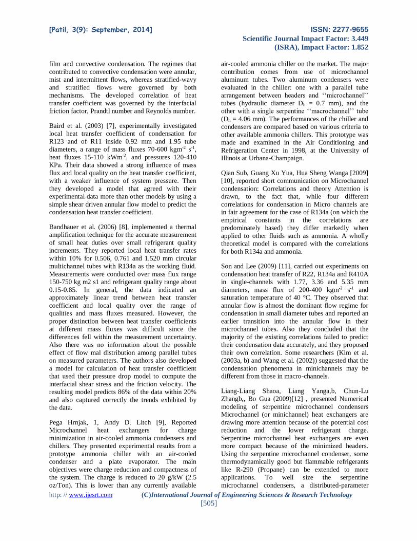
Refrigerant tube diameter: 9mm
Circular coil tube diameter: 200mm
Length of the tube: 600 mm
Volume capacity of brine solution: 10litre
Evaporator type: Wound coil
Evaporator coil material: Copper
Fig. 5 Profile of evaporator
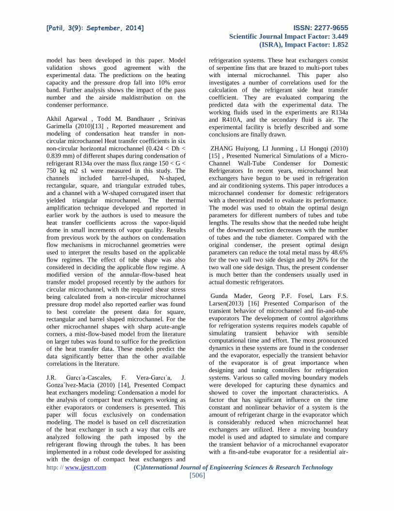
Experimentation For the analysis of refrigeration system
using microchannel condenser set up is built to find
various parameters. The measurement parameters are
actual coefficient of performance, theoretical
coefficient of performance, mass flow rate of
refrigerant, heat rejection ratio, heat rejected by
condenser and heat transfer coefficient. From various
operating conditions the data obtained from
refrigeration system using microchannel condenser
was compared with round tube and coil tube
condenser. In experimental procedure, performance
of microchannel condenser, round tube condenser
and coil tube condenser was compared using two
different refrigerants which are R134a
(Tetrafluoroethane) and R290 (CH3CH2CH3)
propane. The three condensers are connected in series
and operated by closing , opening of throttle valve
shown in figure 6.
Operation procedure:-Connect the two plugs to main.
Before ON the supply, conform that all the switches
on panel are off position. See the dimmerstat is at
zero position. Then put ON the heater switch & give
power to heater. This will heat the water in
evaporator & this can be seen to dial thermometer.
Adjust the heater voltage such that the Temperature
dial thermometer reading reaches 25 - 300 C. Now
ON the D.P. switches. Put ON the condenser fan
switch & wait for 2 - 3 minutes. Now switch ON the
solenoid valve switch & the compressor switch. The
refrigeration flow will start. This can be confirmed on
the sight glass. Now the ammeter, voltmeter will
show the current & voltage for compressor. Note
down the time for 10 revolutions of energy for
compression. After some time we will see that the
Temperature of water in the evaporator slowly goes
down & reaches steady state. (Adjust this temp. at 28
to 300 C). After the steady state note down the
readings as follows:
1. HP Condenser pressure in Kg/cm2. = Kg/cm2
2. LP Evaporator Pressure in Kg/Cm2 = Kg/cm2
3. Rotameter in Reading LPH = LPH
4. Condenser Inlet Temperature in 0C = Tci
5. Condenser Outlet Temperature 0C = Tco
6. Evaporator Inlet Temperature in 0C = Tci
7. Evaporator Outlet Temperature 0C = Teo
8. Time for 10 Pulses of heater energy meter = in sec
(EMC=3200imp. /KW-hr.)
9. Time for 10 Pulses of comp energy meter = in sec.
(EMC=6400imp. /KW-hr.)
10. Ammeter reading = in Amp
11. Voltmeter reading = in V
12. Evaporator Bath Temp in 0C = 0C.

[Patil, 3(9): September, 2014] ISSN: 2277-9655
Scientific Journal Impact Factor: 3.449
(ISRA), Impact Factor: 1.852
http: // www.ijesrt.com (C)International Journal of Engineering Sciences & Research Technology
[510]
Fig. 6 Profile of experimental set-up
Parameters calculated:-
1. Compressor Power (Wact) = 𝑁𝑐∗3600
𝑒𝑚𝑐∗𝑡𝑐
2. Heater power (Nact) = 𝑁ℎ∗3600
𝑒𝑚𝑐∗𝑡ℎ
3. C.O.P act = 𝑊𝑎𝑐𝑡
Nact
4. C.O.P theoretical = 𝐻𝑒𝑜−𝐻𝑒𝑖
𝐻𝑐𝑖−𝐻𝑒𝑜
5. HRR = 1 + 1
𝐶𝑂𝑃
6. Qc = mCp (ΔT)
Results and discussion The experimental data obtained from
three condensers and two refrigerants are presented in
this chapter. To compare performance analysis of
refrigeration system using microchannel condenser,
round tube condenser and coil tube condenser with
refrigerants R134a and R290 various graphs are
plotted. The graphs are obtained from calculations
shown in chapter 5 and results table as shown in this
chapter.
1.Effect of cooling load on actual coefficient of
performance using R134a:-
The coefficient of performance is an index of
performance of a thermodynamic cycle or a thermal
system. Because the COP can be greater than 1, COP
is used instead of thermal efficiency.
Fig.7 C.O.P Vs Cooling load for refrigerant R134a
The coefficient of performance can be used for the
analysis of the following:
A refrigerator that is used to produce a
refrigeration effect only, that is, COPref
A heat pump in which the heating effect is
produced by rejected heat COPhp
A heat recovery system in which both the
refrigeration effect and the heating effect are
used at the same time, COPhr
2. Effect of cooling load on efficiency using R134a
From figure 8 it can be seen that efficiency of
microchannel condenser is more than round tube and
coil tube condenser.
Fig. 8 Efficiency Vs cooling load for R134a
3. Effect of cooling load on theoretical coefficient
of performance using R134a
Figure 9 shows Effect of cooling load on theoretical
coefficient of performance using R134a . It can be
seen from figure that as cooling load increases
theorotical coefficient of performance increases for
all condensers. The increase in coefficeint of
performance is more for microchannel condenser.
Fig. 9 C.O.Pth Vs cooling load for refrigerant R134a
0
0.5
1
1.5
2
2.5
3
175 208 239 261 288
C.O
.P
Microcha
nnel
Round
tube
Coil
Tube
Cooling Load (watt)
R134a
0
5
10
15
20
25
30
35
175 208 239 261 288
Eff
icie
ncy Microcha
nnel
Round
Tube
Coil
Tube
R134a
Cooling Load (watt)
0
2
4
6
8
10
12
175 208 239 261 288
C.O
.Pth
.
Microcha
nnel
Round
Tube
Coil
Tube
Cooling Load, W
R1
34a
[Patil, 3(9): September, 2014] ISSN: 2277-9655
Scientific Journal Impact Factor: 3.449
(ISRA), Impact Factor: 1.852
http: // www.ijesrt.com (C)International Journal of Engineering Sciences & Research Technology
[511]
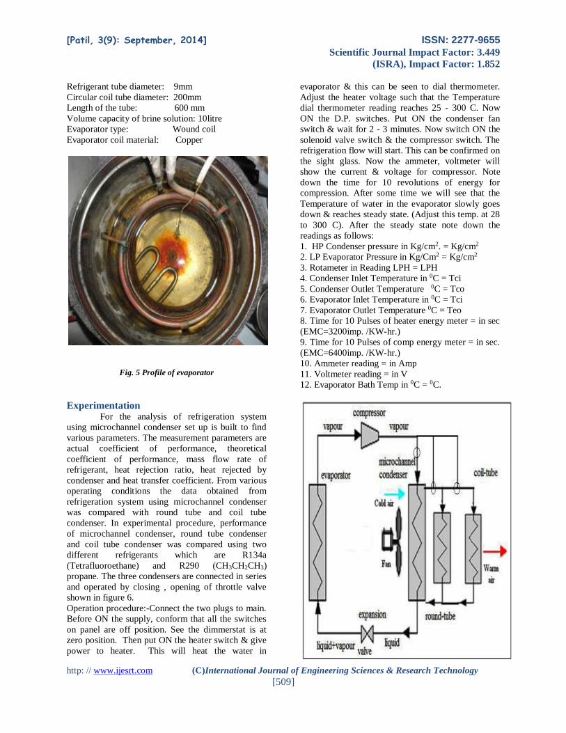
4. Effect of load on C.O.P using R290
Figure 10 shows effect of load on C.O.P and
efficiency using R290. With increase in cooling load
actual coefficient of performance increases. The
increase in COP is more for microchannel condenser.
Fig. 10 C.O.P Vs cooling load for refrigerant R290
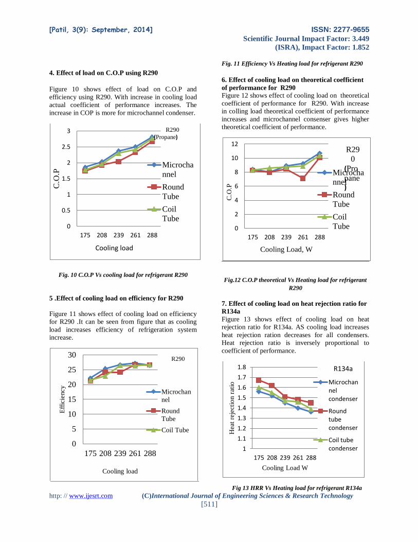
5 .Effect of cooling load on efficiency for R290
Figure 11 shows effect of cooling load on efficiency
for R290 .It can be seen from figure that as cooling
load increases efficiency of refrigeration system
increase.
Fig. 11 Efficiency Vs Heating load for refrigerant R290
6. Effect of cooling load on theoretical coefficient
of performance for R290
Figure 12 shows effect of cooling load on theoretical
coefficient of performance for R290. With increase
in colling load theoretical coefficient of performance
increases and microchannel consenser gives higher
theoretical coefficient of performance.
Fig.12 C.O.P theoretical Vs Heating load for refrigerant
R290
7. Effect of cooling load on heat rejection ratio for
R134a
Figure 13 shows effect of cooling load on heat
rejection ratio for R134a. AS cooling load increases
heat rejection ration decreases for all condensers.
Heat rejection ratio is inversely proportional to
coefficient of performance.
Fig 13 HRR Vs Heating load for refrigerant R134a
0
0.5
1
1.5
2
2.5
3
175 208 239 261 288
C.O
.P
Microcha
nnel
Round
Tube
Coil
Tube
R290
(Propane)
Cooling load
0
5
10
15
20
25
30
175 208 239 261 288
Eff
icie
ncy
Microchan
nel
Round
Tube
Coil Tube
R290
Cooling load
0
2
4
6
8
10
12
175 208 239 261 288C
.O.P
Microcha
nnel
Round
Tube
Coil
Tube
R29
0
(Pro
pane)
Cooling Load, W
1
1.1
1.2
1.3
1.4
1.5
1.6
1.7
1.8
175 208 239 261 288
Hea
t re
ject
ion r
atio
Cooling Load W
Microchannelcondenser
Roundtubecondenser
Coil tubecondenser
R134a

[Patil, 3(9): September, 2014] ISSN: 2277-9655
Scientific Journal Impact Factor: 3.449
(ISRA), Impact Factor: 1.852
http: // www.ijesrt.com (C)International Journal of Engineering Sciences & Research Technology
[512]
8. Effect of cooling load on heat rejected from
condenser for R134a
Figure 14 shows variation in heat rejected from
condenser with cooling load for R134a. Heat rejected
from condenser increases as cooling load increases
but power consumption to drive the compressor to
achieve this load increases.
Fig.14Heat rejected from condenser Vs cooling load
9. Effect of cooling load on heat rejection ratio for
R290
Figure 15 shows effect of cooling load on heat
rejection ratio for R290. As cooling load increases
heat rejection ration decreases for all condensers.
Heat rejection ratio is inversely proportional to
coefficient of performance.
Fig.15 HRR Vs cooling load, watt
10. Effect of cooling load on heat rejected from
condenser for R290
Figure 16 shows variation in heat rejected from
condenser with cooling load for R290. Heat rejected
from condenser increases as cooling load increases
but power consumption to drive the compressor to
achieve this load increases.
Fig.6.10 Heat rejected from condenser Vs Cooling load
for refrigerant R290
11. Effect of cooling load on actual coefficient of
performance for different combination of
condenser and refrigerant
Figure shows effect of cooling load on actual
coefficient of performance for different combination
of condenser and refrigerant. For all condenser actual
coefficient of performance increases with increase in
cooling load. The microchannel condenser using
R290 refrigerant gives highest actual coefficient of
performance.
0
50
100
150
200
250
175 208 239 261 288
Qc
Microcha
nnel
Round
Tube
Coil
Tube
Cooling load W
R134a
11.11.21.31.41.51.61.71.8
175 208 239 261 288
Hea
t re
ject
ion r
atio
Cooling Load W
Microchannelcondenser
Roundtubecondenser
Coil tubecondenser
R290
0
50
100
150
200
250
175 208 239 261 288
Qc
Microchan
nel
Round
Tube
Coil Tube
Cooling load, watt
R290(Propane)
0
0.5
1
1.5
2
2.5
3
175 208 239 261 288
Act
ual
CO
P
Cooling Load
Actual COP Vs Cooling Load
R134a-Micro
R134a-Round
R134a-Coil
R290-Micro
R290-Round
R290-Coil

[Patil, 3(9): September, 2014] ISSN: 2277-9655
Scientific Journal Impact Factor: 3.449
(ISRA), Impact Factor: 1.852
http: // www.ijesrt.com (C)International Journal of Engineering Sciences & Research Technology
[513]
Fig. 16 Heat rejected from condenser Vs Cooling load for
R134A and R290
12. The presentation of pressure, temperature and
enthalpy on P-h chart
Fig. 17 P-h chart at load 175watt (Microchannel
condenser, R134a)
Experimental Validation 1. Theoretical Aspects: In the condenser, . three
zones, corresponding to refrigerant de-superheating,
condensation and Sub-cooling are considered. In the
superheating zone the surface temperature is above
the saturation temperature so there is no condensation
in this region. The real condensation of refrigerant
occurs in the condensation zone , where two phase
flow (a combination of liquid and vapor refrigerant )
exists . A large number of techniques for predicting
the heat-transfer coefficients during condensation
inside pipes have been proposed .These range from
very arbitrary correlations to highly sophisticated
treatments of the mechanics of flow.
2. Shah’s Correlation: The two-phase flow heat
transfer model developed by Shah is a simple
correlation that has been verified over a large range
of experimental data. In fact, experimental data from
over 20 different researchers has been used in its
development. For this model, at any given quality,
the two-phase heat transfer coefficient is defined as:
Nul = 0.023 Rel0.8 Prl 0.4
Where, 0 < x < 1
Rel > 350
Prl > 0.5
Nomenclature used in correlations
Re Reynolds number ρvD/μ
Nu Nusselt number hD/k
Pr Prandtl number Cpμ/k
hr refrigerant-side heat transfer coefficient W/m2.K
hi enthalpy of refrigerant inter condenser kJ/kg
Tsi temperature of inner tube surface ºC
Tao temperature of air outlet ºC
Q rate of heat flow Watt
Ao outside area of tube m2
Ai inside area of tube m2
ρl saturated liquid density kg/m3
α heat transfer coefficient
[W/m2K]
λ thermal conductivity
[W/mK]
D inside diameter of tube [m]
x vapor quality
Pr Prandt number
This correlation takes into account the pressure of the
refrigerant also in addition to the quality of the
mixture. This can also be used to find the local
condensation heat transfer coefficient. The heat
transfer coefficient is a product of heat transfer coefficient given by Dittus-Boelter equation and an
additional term.
The two-phase heat transfer coefficient is defined as:
htp = hl*Y
Where Y = (1-x) 0.8 + 3.8x0.76 (1-x) 0.04 /pr0.38
pr is the reduced pressure = condenser pressure /
critical pressure
To check variation in heat transfer coefficient
between experimental heat transfer coefficient and
Shah’s Correlation heat transfer coefficient various
graphs at cooling loads are obtained.
3. Experimental aspects:
Volume flow rate of refrigerant ,inlet and outlet
temperature of air across the condenser ,air velocity
,and the readings of current ,voltage ,power
consumed are taken using refrigerant R134a at
different volume flow rate at ambient temperature of
(31ºC,28.6ºC,24.3 ºC) .The same measurements are
taken for R290 at ambient temperature of
(31ºC,28.6ºC,24.3 ºC) for comparison purposes. The
condenser is supplied with glass tubes to show the
phase of refrigerant along the condenser.
Once the temperature of refrigerant enters
and leaves the condenser, condenser pressure and

[Patil, 3(9): September, 2014] ISSN: 2277-9655
Scientific Journal Impact Factor: 3.449
(ISRA), Impact Factor: 1.852
http: // www.ijesrt.com (C)International Journal of Engineering Sciences & Research Technology
[514]
volume flow rate are measured then the heat rejected
from condenser Q is calculated as,
Q= m (hi- ho) *1000
Under steady state conditions, the rate of heat transfer
Q is the same from the outside surface to the inside
surface of the tube and from the inside surface of the
tube to the refrigerant. Although the difference
between average outside tube surface temperature
Tso and inner tube surface temperature Tsi is small,
the inner tube surface temperature is calculated as:
Q= (kt/xt) Am (Tso – Tsi)
The average values of experimental heat transfer
coefficient are calculated at average surface
temperature of the condenser as:
Q= hr Ai (Tsat –Tsi)
Fig. 18 Heat transfer coefficient (W/m2K) Vs cooling load
(W)
Conclusion The present work is to find performance
analysis of refrigeration system using microchannel
condenser, round tube condenser and coil tube
condenser with two refrigerants R134a and R290.
Experiments are performed to find the effects of mass
flow rate, the saturation temperature, coefficient of
performance, heat rejection ratio, and heat rejection
rate from condenser with heat transfer coefficient.
For both refrigerants R134a and R290, coefficient of
performance increases with increase in cooling load.
From the three condensers, C.O.P of refrigeration
system using microchannel condenser is more
compared to round tube and coil tube condenser. The
C.O.P of the system with the microchannel condenser
is found 19.75 % higher than that with the round tube
condenser and 8.65 % higher than that with the coil
tube condenser using R134a. The C.O.P of the
system with the microchannel condenser is found
8.21 % higher than that with the round tube
condenser and 4.04 % higher than that with the coil
tube condenser using R290.
For condenser parameters, heat rejection ratio with
the microchannel condenser is 2.39% lower
compared to coil tube condenser and 5.62% lower
with round tube condenser. For a fixed condenser
temperature, as the evaporator temperature decreases
the COP decreases and heat rejection ratio increases.
The heat rejected from microchannel condenser is
15.73% higher compared to round tube condenser
and 7.136 % higher than the coil tube condenser. The
overall temperature after condenser remains same for
both refrigerants as well as for three condensers at
various cooling load.
References [1] D. A. Luhrs and W. E. Dunn, Design and
Construction of a Microchannel Condenser
Tube Experimental Facility. Air
Conditioning and Refrigeration Center
University of Illinois Mechanical &
Industrial Engineering Dept., ACRC TR –
65, July 1994
[2] Riehl, R.R., Seleghim, P. Jr., Ochterbeck,
Comparison of Heat Transfer Correlations
for Single- and Two-Phase Microchannel
Flows for Microelectronics Cooling. Paper
Presented at the Sixth Intersociety
Conference on Thermal and Thermo
mechanical Phenomena in Electronic
Systems, 1998. ITHERM 98.
[3] Yin, J.M. et. Al. 2001 R-744 gas cooler
model development and validation. Int. J.
Refrigeration 24, 692–701.
[4] Cavallini, A., Censi, G., Del Col, D. 2002.
Condensation of halogenated refrigerants
inside smooth tubes. HVAC&R Res. 8 (4),
429-451.
[5] Kim M.H. et. Al. 2003. A Study of
Condensation Heat Transfer in a Single
570
580
590
600
610
620
630
640
650
660
670
175 208 239 261 288
Hea
t tr
ansf
er c
oef
fici
ent
Experimental
Shah'scorrelation
Cooling load
R134a

[Patil, 3(9): September, 2014] ISSN: 2277-9655
Scientific Journal Impact Factor: 3.449
(ISRA), Impact Factor: 1.852
http: // www.ijesrt.com (C)International Journal of Engineering Sciences & Research Technology
[515]
Mini-Tube and a Review of Korean Micro-
and Mini-Channel Studies. Paper Presented
at the ASME 1st International Conference on
Microchannels and Minichannels,
Rochester, New York, USA.
[6] El Hajal, J., Thome, J.R., Cavallini, A.,
2003. Condensation in horizontal tubes, part
1: two-phase flow pattern map. Int. J. Heat
Mass Transfer 46 (18), 3349-3363.
[7] Baird, J.R., Fletcher, D.F., Haynes, B.S.,
2003. Local condensation heat transfer rates
in fine passages. Int. J. Heat Mass Transfer
46 (23), 4453-4466.
[8] Bandhauer, T.M., Agarwal, A., Garimella,
S., 2006. Measurement and modeling of
condensation heat transfer coefficients in
circular microchannels. J. Heat Transfer
128, 1050.
[9] Pega Hrnjak, Andy D. Litch, Microchannel
heat exchangers for charge minimization in
air-cooled ammonia condensers and chillers,
International Journal of Refrigeration, 3 I
(2008) 658- 668.
[10] Qian Sub, Guang Xu Yua, Short
Communication on Microchannel
Condensation: Correlations and Theory,
International Journal of Refrigeration, 32
(2009) II 49- 52
[11] Son, C.H., Lee, H.S., 2009. Condensation
heat transfer characteristics of R-22, R-134a
and R-410A in small diameter tubes. Heat
Mass Transfer 45 (9), 1153-1166.
[12] Liang-Liang Shao, Liang Yang Chun-Lu
Zhang, Bo Gu, Numerical modeling of
serpentine microchannel condensers,
International Journal of Refrigeration, 32
(2009) II 62-72.
[13] Akhil Agarwal, Todd M. Bandhauer,
Srinivas Garimella, Measurement and
modeling of condensation heat transfer in
non-circular microchannels, International
Journal of Refrigeration, 33(2010) II 69- 79.
[14] J.R. Garcıa-Cascales, F. Vera-Garcıa J.
Gonzalvez-Macia, J.M. Corberan-Salvador,
M.W. Johnson, G.T. Kohler, Compact heat
exchangers modeling: Condensation,
International Journal of Refrigeration, 33
(2010) I 35- I 47.
[15] ZHANG Huiyong, LI Junming, LI Hongqi,
Numerical Simulations of a Micro-Channel
Wall-Tube Condenser for Domestic
Refrigerators, TSINGHUA Science and
Technology, ISSN ll1007-
0214ll09/16llpp426-433 Volume 15,
Number 4, August 2010
[16] Gunda Mader, Georg P.F. Fosel, Lars F.S.
Larsen, Comparison Of The Transient
Behavior Of Microchannel And Fin-And-
Tube Evaporators, International Journal of
Refrigeration, 34 (2013) I 222- I 229
[17] G.B. Ribeiro, J.R. Barbosa Jr. A.T. Prata,
Performance of microchannel condensers
with metal foams on the air-side:
Application in small-scale refrigeration
systems, Applied Thermal Engineering 36
(2013) 152-160
[18] Shan K. Wang, Handbook of air
conditioning and refrigeration / Shan K.
Wang-2nd edition, McGraw-Hill
Publications, ISBN 0-07-068167-8/2013
[19] Lessons on Refrigeration and Air
Conditioning from IIT Kharagpur Useful
Training Material for Mechanical
Engineering Students/College, 2008.
Author Biblography
Deepak Padmakar Patil
PG Student,
M.E (Heat Power),
Department of
Mechanical Engineering,
MCERC Eklahare Nasik,
India
Email:
Related Documents


![IJESRT /Archives-2015/July-2015/35_QFD... · http: // © International Journal of Engineering Sciences & Research Technology [249] IJESRT ... (Jnanesh & Hebbar, 2008). Total Quality](https://static.cupdf.com/doc/110x72/5ad42c787f8b9a571e8be123/archives-2015july-201535qfdhttp-international-journal-of-engineering.jpg)