March 26, 2021 Dr. Craig Scratchley Dr. Shervin Jannesar Dr. Andrew Rawicz School of Engineering Science, Simon Fraser University British Columbia, V5A 1S6 RE: ENSC 405W/440 Design Specifications for NovaBand Dear Dr. Scratchley, Dr. Jannesar, and Dr. Rawicz, Attached to this letter you will find the design specifications document for NovaBand, a programmatic resistance device intended for use in physiotherapy clinics for muscular rehabilitation. By working alongside practicing physiotherapists, our company aims to create an affordable, versatile device that facilitates an efficient recovery process for physiotherapy patients through the application of isokinetic exercise. The design specifications document details NovaBand’s functionality and justifies the design choices made. Our design choices are founded in engineering experience, research, and experimentation and were selected to meet the requirements outlined in our previously transmitted requirements specifications document. Our team consists of five senior engineering students, each with a varied engineering background: Kevin Jerome, Arvin Amini, Nicolas Skinner, George Lertzman-Lepofsky, and Jordan Lei. For the last several months, we have been collaborating to create a truly exceptional product. We thank you for taking the time to read this design specifications document. If you have any questions, please reach out to our Chief Communications Officer, George, at [email protected]. Sincerely, Jordan Lei Chief Executive Officer NovaBand Solutions

Welcome message from author
This document is posted to help you gain knowledge. Please leave a comment to let me know what you think about it! Share it to your friends and learn new things together.
Transcript

March 26, 2021
Dr. Craig Scratchley
Dr. Shervin Jannesar
Dr. Andrew Rawicz
School of Engineering Science, Simon Fraser University
British Columbia, V5A 1S6
RE: ENSC 405W/440 Design Specifications for NovaBand
Dear Dr. Scratchley, Dr. Jannesar, and Dr. Rawicz,
Attached to this letter you will find the design specifications document for NovaBand, a
programmatic resistance device intended for use in physiotherapy clinics for muscular
rehabilitation. By working alongside practicing physiotherapists, our company aims to create an
affordable, versatile device that facilitates an efficient recovery process for physiotherapy patients
through the application of isokinetic exercise.
The design specifications document details NovaBand’s functionality and justifies the design
choices made. Our design choices are founded in engineering experience, research, and
experimentation and were selected to meet the requirements outlined in our previously transmitted
requirements specifications document.
Our team consists of five senior engineering students, each with a varied engineering background:
Kevin Jerome, Arvin Amini, Nicolas Skinner, George Lertzman-Lepofsky, and Jordan Lei.
For the last several months, we have been collaborating to create a truly exceptional product.
We thank you for taking the time to read this design specifications document. If you have any
questions, please reach out to our Chief Communications Officer, George, at [email protected].
Sincerely,
Jordan Lei
Chief Executive Officer
NovaBand Solutions

ENSC 405W: Company 6
Design Specifications:
NovaBand
Jordan Lei (CEO)
Kevin Jerome (COO)
Arvin Amini (CTO)
Nicolas Skinner (CFO)
George Lertzman-Lepofsky (CCO)
Contact:
George Lertzman-Lepofsky
i
Version History
Version # Implemented By Revision
Date
Approved
By
Approval
Date
Reason
1.0
Jordan Lei,
Kevin Jerome,
Arvin Amini,
Nicolas Skinner,
George Lertzman-Lepofsky
03/26/21 Jordan Lei 03/26/21
Initial
Design
Definition
Draft

ii
Approvals
Signature:
Date: 03/26/21
Print Name: Jordan Lei
Title: Mr.
Role: Chief Executive Officer
Signature: Date:
Print Name:
Title:
Role:

iii
Abstract
When used for physiotherapy, traditional resistance bands present several issues. First, they are
unable to precisely vary resistive force as they are stretched. Second, the force produced is linearly
related to the displacement of the band. These problems result in suboptimal exercise and
rehabiliatory efficiency; there is a dramatic difference between the muscle-torque curve and the
force applied by the band in the latter half of a given exercise. Existing physiotherapy machines
attempt to address these weaknesses, but ultimately fail to do so for various economic and practical
reasons. To cover these shortcomings, NovaBand Solutions offers a programmatic resistance
device: NovaBand. NovaBand is an affordable, versatile device that works in concert with muscle
characteristics to provide a custom-tailored isokinetic exercise for physiotherapy patients.
Physiotherapists can precisely control the device via a mobile application while their patients
physically interact with the device through carefully controlled exercises.
iv
Contents Version History ....................................................................................................................................................... i
Approvals ................................................................................................................................................................. ii
Abstract .................................................................................................................................................................... iii
Contents ................................................................................................................................................................... iv
Glossary ................................................................................................................................................................... vi
List of Figures ....................................................................................................................................................... vii
List of Tables ....................................................................................................................................................... viii
1. Introduction ....................................................................................................................................................... 1
1.1 Background ................................................................................................................................................. 1
1.2 Scope .............................................................................................................................................................. 1
1.3 System Overview ....................................................................................................................................... 1
2. Mechanical .......................................................................................................................................................... 4
2.1 Braking System .......................................................................................................................................... 4
2.1.1 Braking Mechanism ......................................................................................................................... 4
2.1.2 Brake Pad Material ........................................................................................................................... 7
2.1.3 Brake Rotor ......................................................................................................................................... 7
2.2 Retraction System ..................................................................................................................................... 9
2.3 Housing ...................................................................................................................................................... 10
2.3.1 Layout and Subsystems ............................................................................................................... 10
2.3.2 Structure ........................................................................................................................................... 11
2.3.3 Material ............................................................................................................................................. 12
2.4 Mounting ................................................................................................................................................... 12
2.5 Tension System ....................................................................................................................................... 13
2.5.1 Rope .................................................................................................................................................... 13
2.5.2 Handle ................................................................................................................................................ 15
3. Electronics ........................................................................................................................................................ 15
3.1 Microcontroller ....................................................................................................................................... 15
3.2 Motor Driver ............................................................................................................................................ 17
3.3 Control Systems ...................................................................................................................................... 18
3.4 Power Source ........................................................................................................................................... 19
4. Software ............................................................................................................................................................ 20
4.1 Physiotherapist-to-Device Interface............................................................................................... 20
4.1.1 Mobile Application ........................................................................................................................ 20
4.1.2 Data Transmission ........................................................................................................................ 21
5. Conclusion ........................................................................................................................................................ 23
References ............................................................................................................................................................ 24
Appendix A – Supporting Test Plans .......................................................................................................... 28
A.1 Mechanical ................................................................................................................................................ 28
v
A.1.1 Braking System .............................................................................................................................. 28
A.1.2 Retraction System ......................................................................................................................... 29
A.1.3 Housing, Materials, and Layout ............................................................................................... 29
A.1.4 Mounting System ........................................................................................................................... 30
A.1.5 Tension System .............................................................................................................................. 30
A.2 Electronics ................................................................................................................................................ 30
A.2.1 Microcontroller .............................................................................................................................. 30
A.2.2 Motor Driver ................................................................................................................................... 31
A.2.3 Control Systems ............................................................................................................................. 31
A.2.4 Power Source .................................................................................................................................. 31
A.3 Software .................................................................................................................................................... 32
A.3.1 Physiotherapist-to-Device Interface ...................................................................................... 32
Appendix B – Supporting Design Options ................................................................................................ 33
B.1 Mechanical ................................................................................................................................................ 33
B.1.1 Braking System .............................................................................................................................. 33
B.1.2 Retraction System ......................................................................................................................... 37
B.1.3 Housing, Materials, and Layout................................................................................................ 38
B.1.4 Mounting ........................................................................................................................................... 39
B.1.5 Tension System .............................................................................................................................. 39
B.2 Electronics ................................................................................................................................................ 43
B.2.1 Microcontroller .............................................................................................................................. 43
B.2.2 Motor driver .................................................................................................................................... 45
B.2.3 Control systems ............................................................................................................................. 46
B.2.4 Power source .................................................................................................................................. 48
B.3 Software .................................................................................................................................................... 49
B.3.1 Physiotherapist-to-Device Interface ...................................................................................... 49
B.3.2 Data Transmission ........................................................................................................................ 50
vi
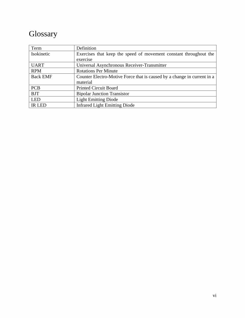
Glossary
Term Definition
Isokinetic Exercises that keep the speed of movement constant throughout the
exercise
UART Universal Asynchronous Receiver-Transmitter
RPM Rotations Per Minute
Back EMF Counter Electro-Motive Force that is caused by a change in current in a
material
PCB Printed Circuit Board
BJT Bipolar Junction Transistor
LED Light Emitting Diode
IR LED Infrared Light Emitting Diode
vii
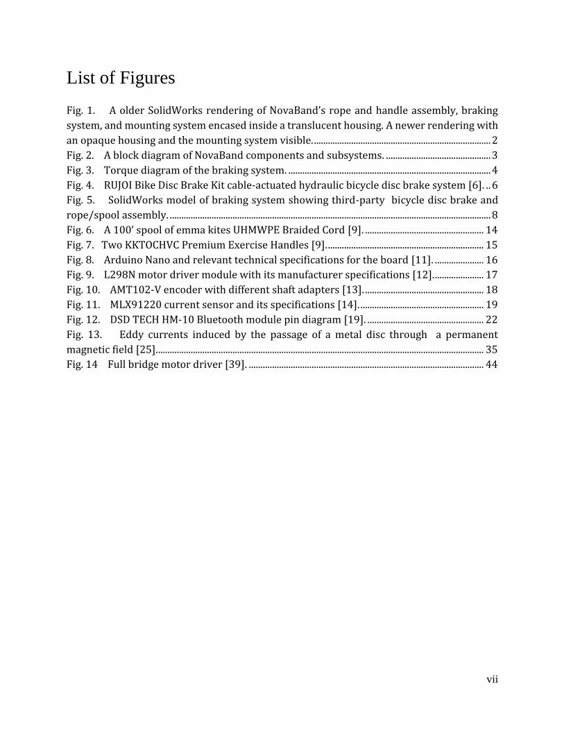
List of Figures
Fig. 1. A older SolidWorks rendering of NovaBand’s rope and handle assembly, braking
system, and mounting system encased inside a translucent housing. A newer rendering with
an opaque housing and the mounting system visible. ............................................................................ 2
Fig. 2. A block diagram of NovaBand components and subsystems. ............................................. 3
Fig. 3. Torque diagram of the braking system. ....................................................................................... 4
Fig. 4. RUJOI Bike Disc Brake Kit cable-actuated hydraulic bicycle disc brake system [6]. .. 6
Fig. 5. SolidWorks model of braking system showing third-party bicycle disc brake and
rope/spool assembly. .......................................................................................................................................... 8
Fig. 6. A 100’ spool of emma kites UHMWPE Braided Cord [9]. ................................................... 14
Fig. 7. Two KKTOCHVC Premium Exercise Handles [9]. ................................................................... 15
Fig. 8. Arduino Nano and relevant technical specifications for the board [11]. ..................... 16
Fig. 9. L298N motor driver module with its manufacturer specifications [12]. ..................... 17
Fig. 10. AMT102-V encoder with different shaft adapters [13]. ................................................... 18
Fig. 11. MLX91220 current sensor and its specifications [14]. ..................................................... 19
Fig. 12. DSD TECH HM-10 Bluetooth module pin diagram [19]. .................................................. 22
Fig. 13. Eddy currents induced by the passage of a metal disc through a permanent
magnetic field [25]. ............................................................................................................................................ 35
Fig. 14 Full bridge motor driver [39]. ..................................................................................................... 44

viii
List of Tables
TABLE I DESIGN SPECIFICATIONS FOR THE BRAKING SYSTEM ........................................................................... 7
TABLE II DESIGN SPECIFICATIONS FOR THE BRAKE PAD MATERIAL ................................................................. 7
TABLE III DESIGN SPECIFICATIONS FOR BRAKE ROTOR...................................................................................... 8
TABLE IV DESIGN SPECIFICATIONS FOR THE RETRACTION SYSTEM .................................................................. 9
TABLE V DESIGN SPECIFICATIONS FOR THE HOUSING SYSTEM ....................................................................... 10
TABLE VI DESIGN SPECIFICATIONS FOR THE LAYOUT ...................................................................................... 10
TABLE VII DESIGN SPECIFICATIONS FOR THE STRUCTURE .............................................................................. 11
TABLE VIII DESIGN SPECIFICATIONS FOR THE MATERIALS ............................................................................. 12
TABLE IX DESIGN SPECIFICATIONS FOR THE MOUNTING SYSTEM .................................................................. 13
TABLE X DESIGN SPECIFICATIONS FOR THE ROPE ............................................................................................ 14
TABLE XI DESIGN SPECIFICATIONS FOR THE HANDLE ...................................................................................... 15
TABLE XII DESIGN SPECIFICATIONS FOR THE MICROCONTROLLER ................................................................ 16
TABLE XIII DESIGN SPECIFICATIONS FOR THE MOTOR DRIVER ...................................................................... 17
TABLE XIV DESIGN SPECIFICATIONS FOR THE CONTROL SYSTEMS ................................................................ 18
TABLE XV DESIGN SPECIFICATIONS FOR THE POWER SOURCE ....................................................................... 19
TABLE XVI DESIGN SPECIFICATIONS FOR MOBILE APP ................................................................................... 21
TABLE XVII TECHNICAL SPECIFICATIONS FOR BLUETOOTH LOW ENERGY [18] .......................................... 21
TABLE XVIII DESIGN SPECIFICATIONS FOR DATA TRANSMISSION ................................................................. 22
TABLE XIX PRODUCT OPTIONS FOR MECHANICAL DISC BRAKES ................................................................... 33
TABLE XX PRODUCT OPTIONS FOR HYDRAULIC DISC BRAKES ....................................................................... 34
TABLE XXI PRODUCT OPTIONS FOR BRAKE PAD MATERIALS ........................................................................ 36
TABLE XXII BRAKE ROTOR MATERIAL PROPERTIES ....................................................................................... 36
TABLE XXIII PRODUCT OPTIONS FOR THE BRAKE ROTOR .............................................................................. 37
TABLE XXIV PRODUCT OPTIONS FOR RETRACTION SYSTEM ........................................................................... 38
TABLE XXV CHARACTERISTICS OF COMMON TYPES OF LINES [31] .............................................................. 40
TABLE XXVI PRODUCT OPTIONS FOR THE ROPE .............................................................................................. 41
TABLE XXVII DESIGN OPTIONS FOR HANDLE ................................................................................................... 42
TABLE XXVIII DESIGN OPTIONS FOR MICROCONTROLLER ............................................................................. 43
TABLE XXIX DESIGN OPTIONS FOR MOTOR DRIVER ........................................................................................ 45
TABLE XXX DESIGN OPTIONS FOR ENCODER .................................................................................................... 46
TABLE XXXI DESIGN OPTIONS FOR CURRENT SENSE CHIP ............................................................................. 47
TABLE XXXII DESIGN OPTIONS FOR POWER SOURCE ...................................................................................... 47
TABLE XXXIII DESIGN OPTIONS FOR DATA TRANSMISSION ........................................................................... 50
1
1. Introduction 1.1 Background
NovaBand is a programmatic resistance device designed to aid physiotherapists and their patients
undergoing muscular rehabilitation. NovaBand aims to be a direct replacement for traditional
resistance bands. These resistance bands are only able to increase tension mid-exercise and exert
force in a way that diverges from the typical joint-angle curve observed in common muscle groups
[1] [2], potentially leading to slower patient rehabilitation times or further injury.
Existing physiotherapy machines attempt to solve these two issues by having the patient perform
an isokinetic exercise, which is carried out at a constant velocity and has clear benefits for both
strength building and muscular rehabilitation [3]. However, these machines are cumbersome and
expensive and are therefore not used outside of research and specialized clinics [4]. In contrast,
NovaBand aims to provide a portable, low-cost, and versatile medical device that makes isokinetic
exercise accessible to patients in a way that was not previously possible. NovaBand is also very
convenient for physiotherapists by eliminating the need for multiple sets of bands.
1.2 Scope
This document provides justification and appropriate background explanation for each of the major
subsystems that constitute the proof-of-concept version of NovaBand, and, if known, later versions
of the product.
Each design section illustrates the purpose of a particular device subsystem, lists relevant design
specifications, and offers justification for the final design choice selected. Appendix A contains
supporting test plans that ensure each design specification is achieved. Appendix B provides
additional subsystem justification and outlines alternative design choices that were researched for
each subsystem.
1.3 System Overview
NovaBand consists of two distinct elements: a physical device (herein referred to as “the device”)
and a mobile phone application (herein referred to as “the app”) which provides a software user
interface for the device. Most often, patients will interact with the device itself while a
physiotherapist will primarily use the app. Fig. 1(a) shows a partial SolidWorks rendering of the
device. Note that some device subsystems are not included in Fig. 1(a) for brevity and clarity. Fig.
1(a) is an alternative placement for the handle and pictures an experimental handle used for testing
on the back of the system. Fig. 1(b) shows a Solidworks rendering of the device with an opaque
housing. A mounting system is visible on the right side of the body of the device.
As introduced previously, NovaBand aims to provide patients with a truly isokinetic exercise. To
achieve this, the device must be able to closely match the force exerted by a patient as they perform
an exercise repetition. Patients interact with the device by exerting a pulling force on a handle
connected to a rope that is precisely unspooled from the device. The device subsystem used to

2
counteract the force applied by the patient is referred to as the “braking system” can be seen on
the right-hand side of Fig. 2. As the patient pulls, a sophisticated control system instructs the
internal braking system on the exact configurations needed to match this pulling force.
(a) (b)
Fig. 1. A older SolidWorks rendering of NovaBand’s rope and handle assembly, braking
system, and mounting system encased inside a translucent housing. A newer rendering with an
opaque housing and the mounting system visible.
Once the device has spooled out rope, a subsystem is required to reel the rope back in to prepare
for the next exercise. This subsystem is referred to as the “retraction system” and is pictured on
the left-hand side of Fig. 2.
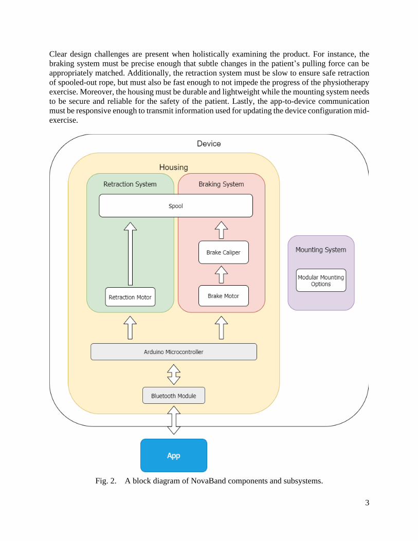
To coordinate the braking and retraction subsystems, a microcontroller is used. The
microcontroller, also shown in Fig. 2, communicates with each subsystem to provide configuration
instructions. It also transmits and receives data to and from the app, respectively, via an electrically
connected Bluetooth module. As shown in Fig. 1, these systems are contained in a box-like housing
which serves to separate these systems from the external environment and protect the patient.
However, one system exists outside of the housing: the “mounting system”. The mounting system,
shown on the right of the housing in Fig. 1(b), secures the device to a surface to prevent excess
movement while an exercise is being carried out by a patient. This subsystem is also shown on the
right-hand side of Fig. 2.
3
Clear design challenges are present when holistically examining the product. For instance, the
braking system must be precise enough that subtle changes in the patient’s pulling force can be
appropriately matched. Additionally, the retraction system must be slow to ensure safe retraction
of spooled-out rope, but must also be fast enough to not impede the progress of the physiotherapy
exercise. Moreover, the housing must be durable and lightweight while the mounting system needs
to be secure and reliable for the safety of the patient. Lastly, the app-to-device communication
must be responsive enough to transmit information used for updating the device configuration mid-
exercise.
Fig. 2. A block diagram of NovaBand components and subsystems.
4
2. Mechanical
While NovaBand is controlled by the software and electronic subsystems, it is primarily a
mechanical device: its mechanical subsystems perform the most important functions of the
product. While there may not necessarily be clear division in mechanical components for the proof-
of-concept device, they are sectioned-off here for clarity.
2.1 Braking System
The braking system is truly the core of NovaBand – it is the reason for all other mechanical,
electronic, and software-based subsystems. The system also has very high interplay: it interacts
directly with the Retraction System (Section 2.2), the Housing (Section 2.3), the Motor Driver
(Section 3.2), the Control Systems (Section 3.3), and the rope spool.
In essence, the braking system applies a resistive force acting against any force applied that works
to unspool the rope from the device as well as implementing inputted resistance curves. This
braking force is required to be highly precise, accurate, and fidelitous: any dramatic deviation from
the expected applied force causes a failure in NovaBand’s primary purpose (isokinetic exercise),
as well is potentially injurious to the patient. Furthermore, this force must be able to be engaged
or disengaged rapidly in case of sudden changes in the velocity of the exercise – again to both
maintain a constant velocity and prevent injury.
2.1.1 Braking Mechanism
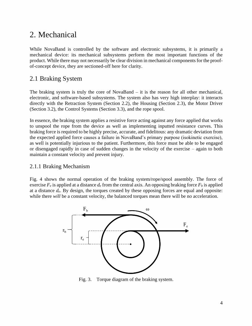
Fig. 4 shows the normal operation of the braking system/rope/spool assembly. The force of
exercise Fe is applied at a distance de from the central axis. An opposing braking force Fb is applied
at a distance de. By design, the torques created by these opposing forces are equal and opposite:
while there will be a constant velocity, the balanced torques mean there will be no acceleration.
Fig. 3. Torque diagram of the braking system.

5
∑ τ𝑖 = 0 ⟶ 𝐹𝑏𝑟𝑏 = 𝐹𝑒𝑟𝑒 , (1)
𝐹𝑏 =𝐹𝑒𝑟𝑒
𝑟𝑏. (2)
If we take the maximum Fe to be 140N (defined by Req. 3.1.3), the radius of the spool to be 5.0cm,
and the radius of the disc to be 8cm, we have:
𝐹𝑏 =𝐹𝑒𝑟𝑒
𝑟𝑏=
140 ⋅ 0.05
0.08= 87.5𝑁. (3)
This gives an upper bound on the required resistive force. This is related to the applied force Fa
through the coefficient of friction of the braking surface, μ:
𝐹𝑏 = μ𝐹𝑎, (4)
where Fa gives the true force required by the brake. If we consider the distance of an exercise de
to be the hypotenuse of the triangle created by the arc of the exercise, we have
𝑑𝑒 = √2𝑎2 = √2𝑎, (5)
where a is the length of limb performing the exercise. A length of rope de unspooled from the
device will cause the spool itself to rotate sb times, proportional to its radius:
𝑠𝑏 =𝑑𝑒
𝑟𝑒. (6)
We can consider a to be the average length of a male forearm, approximately 25.40 cm [5]. The
brake rotor must rotate the same amount, so we can relate the above braking force to work W as
follows:
𝑊 = 𝐹 ⋅ 𝑑 = 𝐹𝑏
√2 𝑎
𝑟𝑒
(2π𝑟𝑏) = (87.5)(7.18)(2π0.08) = 316𝐽. (7)
This is an upper bound on the amount of energy output required by the braking system in a given
exercise. Now,
𝑃 =𝑊
𝑡, (8)
where P is the power output by the brake during an exercise. If we assume a reasonable exercise
to take two seconds, we have:
𝑃𝑏 =316
2= 156𝑊. (9)
6
Again, this is an upper bound on the power output by the braking system but will provide an
adequate target for design considerations. Realistically, the power involved in a standard exercise
(and thus the heat input to the rotor) will be much less: most physiotherapeutic exercises are
performed slowly and at low weight (the equivalent of Fb).
When selecting a braking mechanism, the following qualities were considered:
1) maximize holding strength;
2) maximize fidelity in instantaneous braking force;
3) minimize actuation time;
4) minimize diameter;
5) maximize durability;
6) minimize weight;
7) minimize cost.
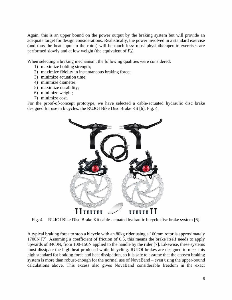
For the proof-of-concept prototype, we have selected a cable-actuated hydraulic disc brake
designed for use in bicycles: the RUJOI Bike Disc Brake Kit [6], Fig. 4.
Fig. 4. RUJOI Bike Disc Brake Kit cable-actuated hydraulic bicycle disc brake system [6].
A typical braking force to stop a bicycle with an 80kg rider using a 160mm rotor is approximately
1700N [7]. Assuming a coefficient of friction of 0.5, this means the brake itself needs to apply
upwards of 3400N, from 100-150N applied to the handle by the rider [7]. Likewise, these systems
must dissipate the high heat produced while bicycling. RUJOI brakes are designed to meet this
high standard for braking force and heat dissipation, so it is safe to assume that the chosen braking
system is more than robust-enough for the normal use of NovaBand – even using the upper-bound
calculations above. This excess also gives NovaBand considerable freedom in the exact
7
dimensions and materials of the rotor and the brake pads, which may dramatically affect the
maximum braking forces.
Cable-actuated hydraulic disc brakes combine the best of traditional mechanical disc brakes and
pure hydraulic disc brakes: they do not require NovaBand to design a specialized piston to
compress the brake line and retain the better modulation and increased braking force of hydraulic
brakes. Details about the performance and design of the braking system are given in TABLE I.
TABLE I
DESIGN SPECIFICATIONS FOR THE BRAKING SYSTEM
Specification ID Specification Description Requirement
Reference ID
Des 2.1.1 A The RUJOI cable-actuated hydraulic disc brake shall
apply a variable resistive braking force to a rotor attached
to the rope spool.
Req 3.3.5 A
Des 2.1.2 A The RUJOI braking system will take input from the
Control System and the app to increase or decrease the
applied braking force.
Req 3.3.6 A
Des 2.1.3 B The RUJOI braking system shall be able to apply forces
of at least 140N.
Req 3.1.3 B
2.1.2 Brake Pad Material
The RUJOI braking system can apply a much larger braking force than is likely needed in
NovaBand. As well, testing has revealed that unmodified bike brakes are unable to reach the
necessary level of fidelity in braking force. To address this, the brake pads will be modified to hold
a piece of felt cloth to the rotor, rather than the stock sintered metal. Further testing has revealed
that the modified felted brake pads give higher fidelity in the braking force. Furthermore, the cloth
surface reduces (or eliminates) the noise produced while braking. Details about the performance
and design of this component are given in TABLE II.
TABLE II
DESIGN SPECIFICATIONS FOR THE BRAKE PAD MATERIAL
Specification ID Specification Description Requirement
Reference ID
Des 2.1.4 A The brake pad will be covered in felt to increase the
fidelity of braking force.
Req 3.1.1 A
Des 2.1.5 B The felted material of the brake pad will dampen any
noise produced by the frictional braking to within 60dB.
Req 3.3.8 B
2.1.3 Brake Rotor
The primary design considerations for the brake rotor are weight, heat dissipation, size, and
structural integrity. Standard bicycle brake rotors range from 140mm to 205mm, of which the
8
smallest has been selected – to minimize weight and overall size of the device. When used on
bicycles, larger rotors are valued for increased heat dissipation, but NovaBand operates these
brakes at such low forces (3) and produces such little heat (9) relative to their normal application
that heat dissipation should not be a concern, even with a smaller rotor. To compromise between
weight, heat dissipation, structural integrity, and braking modulation, NovaBand will use a Jagwire
140mm hybrid aluminum-and-steel rotor [8]. This rotor gives substantial weight savings (25%)
and thermal dissipation over 100% steel rotors, while maintaining the increased braking
modulation and durability of a steel braking surface. Details about the performance and design of
this component are given in TABLE III.
TABLE III
DESIGN SPECIFICATIONS FOR BRAKE ROTOR
Specification ID Specification Description Requirement
Reference ID
Des 2.1.6 A The Jagwire brake rotor will provide adequate structural
integrity to withstand the braking force applied during an
exercise.
Req 3.3.5 A
Des 2.1.7 B The Jagwire brake rotor will provide adequate heat
dissipation.
Req 3.3.7 B
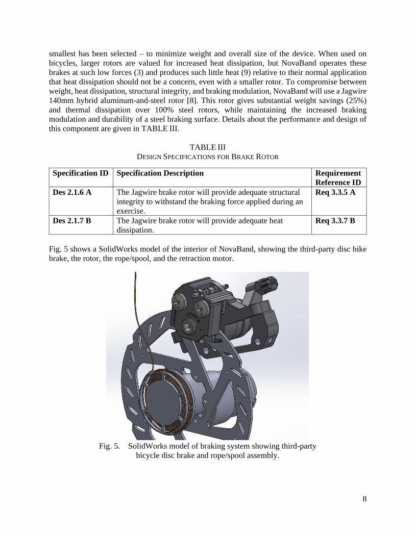
Fig. 5 shows a SolidWorks model of the interior of NovaBand, showing the third-party disc bike
brake, the rotor, the rope/spool, and the retraction motor.
Fig. 5. SolidWorks model of braking system showing third-party
bicycle disc brake and rope/spool assembly.
9
2.2 Retraction System
To successfully complete an exercise repetition, the rope spooled out during the first half of an
exercise must be retracted back towards the device once the exercise is completed. Once fully
retracted, the device state will be properly configured, allowing for another exercise repetition to
begin. To be able to meet retraction time requirements while having enough power to retract the
rope a 24V, a 178RPM DC motor was chosen. This motor will be attached to a spool inside the
device and is activated when instructed by the microcontroller.
As the motor is connected to the spool directly, it is possible to calculate the estimated maximum
speed of rope while retracting. Equation (10) shows the formula for calculating the speed of rope,
v, given a spool of radius r:
𝑣 = 𝑟ω. (10)
To be able to use (10), the 178RPM rotational speed of the motor must be converted to rad/s speed.
As shown in (11), the rotational speed of the motor is calculated to be 18.64rad/s:
1𝑅𝑃𝑀 =2π
60𝑟𝑎𝑑/𝑠 → 178𝑅𝑃𝑀 = 18.64𝑟𝑎𝑑/𝑠. (11)
Using this rotational speed and (10), we can calculate the rope speed using (12):
𝑣 = 1.6𝑐𝑚 ∗ 18.64𝑟𝑎𝑑/𝑠 = 29.824𝑐𝑚/𝑠. (12)
The calculated rope speed in (12) is the maximum speed that the rope reaches while being retracted
by the retraction motor. TABLE IV summarizes the design specifications for the retraction system
and its related requirement specifications.
TABLE IV
DESIGN SPECIFICATIONS FOR THE RETRACTION SYSTEM
Specification ID Specification Description Requirement
Reference ID
Des 2.2.1 A As soon as encoders detect an input force, a hardware
interrupt will be activated that stops the retracting motor
from winding the rope.
Req 3.3.9 A
Des 2.2.2 A The retraction motor is hardware limited at 178RPM
which equates to maximum of 0.3m/s rope speed.
Reg 3.3.10 A
Des 2.2.3 A As soon as encoders detect that there is no input force, a
hardware interrupt will be activated that makes the
retracting motor begin winding the rope.
Req 3.3.11 B
Des 2.2.4 A At the 0.3m/s maximum rope speed based on Des 2.2.2 A
the 0.9m rope of NovaBand will retract in three seconds.
Req 3.3.12 B
10
2.3 Housing
The housing encloses the physical parts of the NovaBand device. In general, the housing can be
considered a single unit, or box, which encloses the mechanical and electronic components. The
housing is designed to protect the user from the movement and potentially noxious temperatures
of internal components, as well as the subsystems from potential damage from drops or external
sources. TABLE V highlights the design specifications for the housing system.
TABLE V
DESIGN SPECIFICATIONS FOR THE HOUSING SYSTEM
Specification ID Specification Description Requirement
Reference ID
Des 2.3.1 A All of the electronic and mechanical components, except
for the rope and handle, will be enclosed in the device.
None of the internal components will be directly
accessible.
Req 3.3.15 B
2.3.1 Layout and Subsystems
The layout is how the internal components are placed in the device. The positioning of the
components needs to be optimized to balance the size of the device with the thermal output of each
component.
TABLE VI highlights the design specifications for the layout and how it will be optimized for
space and user feedback.
TABLE VI
DESIGN SPECIFICATIONS FOR THE LAYOUT
Specification ID Specification Description Requirement
Reference ID
Des 2.3.2 A
The layout of internal components shall minimize the
space used, without leading to thermal issues.
Req 3.3.3 B
Req 3.2.10 P
Des 2.3.3 B
Components such as buttons and LEDs will be on the
surface of the device to serve as input and feedback to the
user.
N/A
The following subsystems will be included inside of the housing:
1) a tension system;
2) a retraction system;
3) the encoders and sensors;
4) and all other electronic components named in Section 3.

11
The following components will not be inside of the housing:
1) a smartphone;
2) the user interface to customize and control the internal components.
Some components, including but not limited to buttons/switches to turn the device on and off, will
also be on the surface of the housing to give the user visual feedback on the state of the device
(e.g. the device is on or paired over Bluetooth) and some means of control without a phone.
2.3.2 Structure
There will be two general elements to consider when looking at the design of the housing. One
will be the interior structure which will hold together all the mechanical and electronic
components. The other is the exterior structure which will be added to enclose the entire device.
TABLE VII highlights the design specifications for the internal and external structures and their
interaction with other components of the device.
TABLE VII
DESIGN SPECIFICATIONS FOR THE STRUCTURE
Specification ID Specification Description Requirement
Reference ID
Des 2.3.4 A The internal and external structures should be reliably
connected but easy to connect and disconnect when
necessary for maintenance.
N/A
Des 2.3.5 A
The internal structure shall hold all the internal
components reliably.
Req 3.2.11 B
Des 2.3.6 B
The external structure will be made from soft plastic to
avoid hurting users or the device without significant
additional forces applied.
Req 3.2.4 B
Req 3.3.14 B
Internal Structure
The internal structure is designed to hold the internal components of the device, as well as maintain
the layout should any external forces get applied. Each of the components will be mounted onto
the internal structure. This structure should be rigid and resist any change in shape, which is why
aluminum was chosen as the material.
External Structure
The external structure, or shell, has two primary functions: to protect the user from any motion,
heat, or electricity in the internal components, and to protect the internal components from any
external damage.
The shell will have no sharp corners or edges so that it will not easily hurt the user without
excessive force.

12
2.3.3 Material
The materials for the internal structure must be rigid and strong while not being too heavy for a
user to carry. Aluminum is a good choice under these restrictions. A metal also provides the benefit
of acting as a heat sink to dissipate any unwanted heat generated in any of the subsystems.
The material of the external structure should be light and soft to keep it easy to carry, dampen any
drops or forces onto the device, and not hurt the user under normal conditions. For these
restrictions, plastic would be the ideal material.
TABLE VIII highlights the design specifications for the materials of both the internal and external
structures.
TABLE VIII
DESIGN SPECIFICATIONS FOR THE MATERIALS
Specification ID Specification Description Requirement
Reference ID
Des 2.3.7 A The internal structure shall be made from aluminum. N/A
Des 2.3.8 B
The material of the external structure shall be made of soft
plastic to shield the user from electrical and thermal
damage and product the internal components.
Req 3.2.12 P
Req 3.3.13 A
Des 2.3.9 B
The material of the external structure will not block
Bluetooth signals.
Req 3.4.2 B
One of the overall goals is for the materials to be lightweight, to keep the device fairly portable.
For the external structure, NovaBand will use a soft plastic material. This will give the flexibility
in the shape and design of the shell. Plastic will also not black any Bluetooth signals used for
communication between the device and the app.
2.4 Mounting
As a multipurpose device, our device will need to be mounted in different locations and situations.
The mounting system will be a modular mechanism, where different mounting systems can be
mounted to the main device and swapped out with other systems. For proof-of-concept, a door
mount will be used which is shown in Fig. 1.
TABLE IX highlights the design specifications for the mounting system which include the modular
mounting system and how it is attached to the device in the beta product.

13
TABLE IX
DESIGN SPECIFICATIONS FOR THE MOUNTING SYSTEM
Specification ID Specification Description Requirement
Reference ID
Des 2.4.1 A The mounting system shall be attached to the housing. Req 3.1.2 B
Req 3.3.17 A
Des 2.4.2 B The mounting system shall be modular to allow different
mechanisms to be mounted in different environments.
Req 3.3.19 P
Des 2.4.3 B The modular mounts shall be held firmly via a locking
mechanism, with a release system.
Req 3.2.8 B,
Req 3.3.18 B
One of the obstacles expressed by physiotherapists while using resistance bands was difficulty in
finding places they can mount them for patients to do their exercises properly. As many
environments are different, from homes to offices to clinics, a modular system is the best choice.
Modularity gives us the possibility to design various mounts that will be better in certain situations.
For the purpose of proof-of-concept prototype, a single mount design is being considered, which
attaches to a door.
In beta, these mounts would have a locking mechanism which will give them a reliable connection
and not slip out during use. When swapping the mount is desired, the user will be able to release
the lock via a mechanical latch to attach a new mount.
2.5 Tension System
The tension system is a point of constant and direct contact with the patient. The core design
parameters are safety, reliability, and comfort, while avoiding compromising the functionality of
the device.
2.5.1 Rope
The primary design considerations for the rope are as follows:
1) minimize diameter;
2) maximize strength;
3) minimize stretch;
4) minimize cost;
5) maximize durability;
6) minimize weight.
To match these constraints, emma kites UHMWPE Braided Cord [9] – ultra-high molecular weight
polyethylene has been selected. This product is marketed as having the “least stretch” (only 4.5%
elongation at breaking weight) and is rated for a maximum load of 350lb (1556.88N, 158.7kg).
Minimum stretch is a high priority, as any non-programmatic stretch during an exercise will cause
a deviation from the intended torque-muscle curve. Typical maximum recommended working
load-limit for ropes is 20% of the rope break-strength [10], so this rope comfortably exceeds the
tension specified by Req. 3.3.1 A with a 2.22 times safety margin (or room for an increased
14
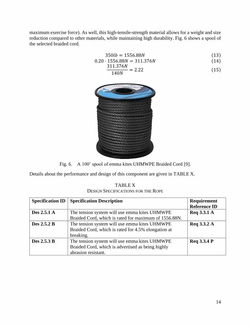
maximum exercise force). As well, this high-tensile-strength material allows for a weight and size
reduction compared to other materials, while maintaining high durability. Fig. 6 shows a spool of
the selected braided cord.
350𝑙𝑏 = 1556.88𝑁 (13)
0.20 ⋅ 1556.88𝑁 = 311.376𝑁 (14) 311.376𝑁
140𝑁= 2.22 (15)
Fig. 6. A 100’ spool of emma kites UHMWPE Braided Cord [9].
Details about the performance and design of this component are given in TABLE X.
TABLE X
DESIGN SPECIFICATIONS FOR THE ROPE
Specification ID Specification Description Requirement
Reference ID
Des 2.5.1 A The tension system will use emma kites UHMWPE
Braided Cord, which is rated for maximum of 1556.88N.
Req 3.3.1 A
Des 2.5.2 B The tension system will use emma kites UHMWPE
Braided Cord, which is rated for 4.5% elongation at
breaking.
Req 3.3.2 A
Des 2.5.3 B The tension system will use emma kites UHMWPE
Braided Cord, which is advertised as being highly
abrasion resistant.
Req 3.3.4 P

15
2.5.2 Handle
The handle is the mechanism by which the user interacts with the main functionality of the device.
The handle that has been selected can be viewed in Fig. 7. The KKTOCHVC Premium Exercise
Handles are ideal in terms of grip and comfort during exercises.Fig. 7. Two KKTOCHVC
Premium Exercise Handles .
Fig. 7. Two KKTOCHVC Premium Exercise Handles [9].
TABLE XI
DESIGN SPECIFICATIONS FOR THE HANDLE
Specification ID Specification Description Requirement
Reference ID
Des 2.5.4 A The handle is ideally sized and ergonomically shaped to
comfortably fit the human hand.
Req 3.3.3 B
Des 2.5.5 B The handle can be easily unclipped and swapped with other
handles or mounts using the same mechanism.
N/A
The rope is attached to the loop on the handle. As the user pulls on the handle, they will unspool
the rope and work directly against the braking system.
The handle will be a modular system. The user will be able to swap the handle out for other handles
or mounts, which enables them to work out other muscle groups that are not able to hold the handle.
3. Electronics
Electronic processing components are required to coordinate NovaBand’s various subsystems. The
electronic components act as a bridge between the mechanical and software systems.
3.1 Microcontroller
In essence, the microcontroller is the brains of the project that connects each piece of hardware
together and allows them to communicate with the software. However, the Novaband
microcontroller does not require any complex calculations to operate successfully.

16
NovaBand requires a microcontroller to send the proper signals to the drivers to control the motors.
It must also communicate with the Bluetooth module using the UART protocol. TABLE
XIITABLE IV shows the design specifications for the microcontroller and its related requirement
specifications.
TABLE XII
DESIGN SPECIFICATIONS FOR THE MICROCONTROLLER
Specification ID Specification Description Requirement
Reference ID
Des 3.1.1 A The microcontroller shall be able to communicate with the
motor drivers.
Req 3.4.2 B
Des 3.1.2 A The microcontroller shall support the UART
communication protocol.
N/A
Des 3.1.3 A The microcontroller shall be able to communicate with
encoders.
Req 3.4.2 B
Des 3.1.4 B The microcontroller shall be able to communicate with
tension sensors.
Req 3.4.2 B
Des 3.1.5 B The microcontroller shall support hardware interrupts. N/A
The Arduino Nano is a simple microcontroller designed for use in small projects with no need for
large amounts of processing power. The Arduino Nano and its relevant technical specifications
can be seen in Fig. 8(a) and Fig. 8(b), respectively.
(a) (b)
Fig. 8. Arduino Nano and relevant technical specifications for the board [11].
17
3.2 Motor Driver
As the power output of the microcontroller alone is not enough to drive the motors, there is a need
for motor drivers. A motor driver module is a H-bridge with back EMF protection that can translate
the low-power digital output of the microcontroller into the high-power signal that is needed to
drive a motor. TABLE XIIITABLE IV shows the design specifications for the motor driver.
TABLE XIII
DESIGN SPECIFICATIONS FOR THE MOTOR DRIVER
Specification ID Specification Description Requirement
Reference ID
Des 3.2.1 A The motor driver shall handle voltages up to 24V. N/A
Des 3.2.2 A The motor driver shall handle two motors independently. N/A
Des 3.2.3 A The motor driver shall handle current draws up to 2A. N/A
Des 3.2.4 A The motor driver shall handle communication with the
microcontroller.
Req 3.4.2 B
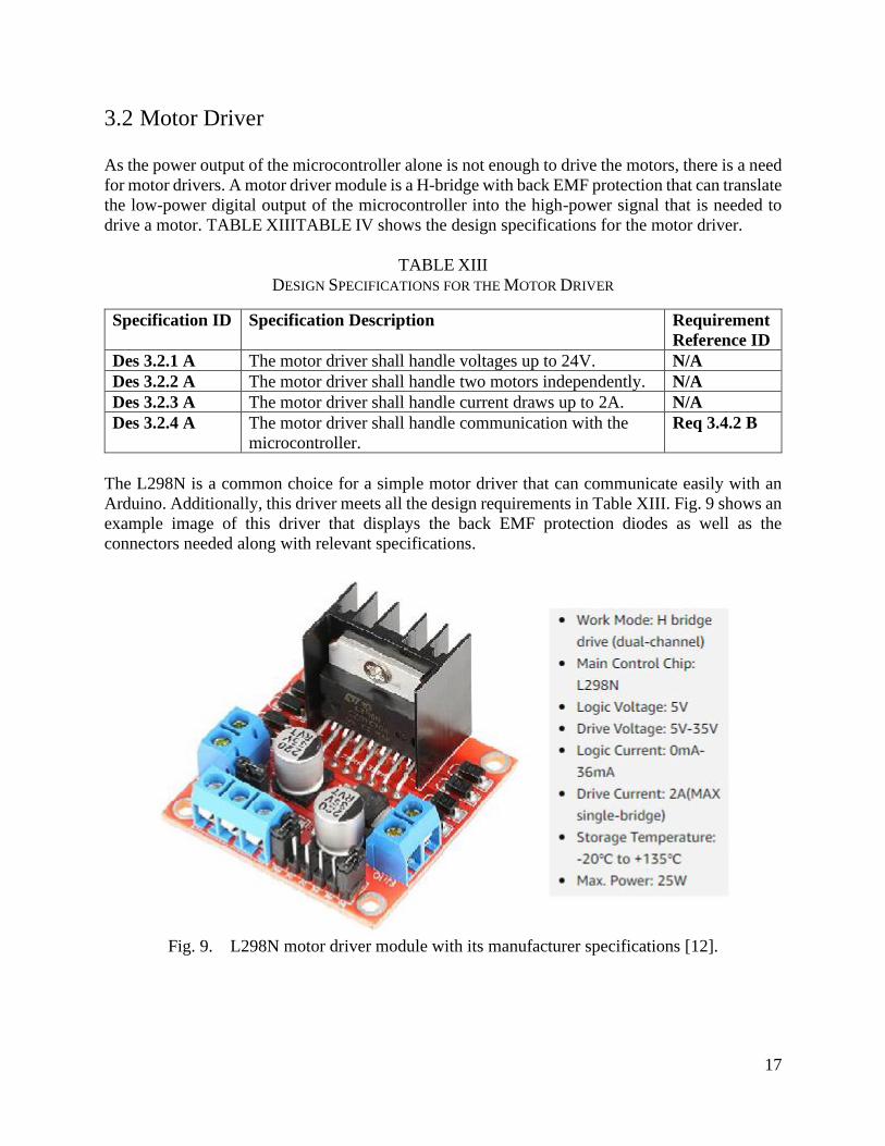
The L298N is a common choice for a simple motor driver that can communicate easily with an
Arduino. Additionally, this driver meets all the design requirements in Table XIII. Fig. 9 shows an
example image of this driver that displays the back EMF protection diodes as well as the
connectors needed along with relevant specifications.
Fig. 9. L298N motor driver module with its manufacturer specifications [12].
18
3.3 Control Systems
The NovaBand device requires a proper control system to achieve precise management over rope
tension and speed during an exercise. A few control mechanisms are available for use. For
example, by using encoders, the rope speed can be measured in order to be maintained when
preforming isokinetic exercises. In addition, NovaBand will have a current sense chip that is able
to measure the amount of power consumed by each of the motors. Using the current sensors, the
device is able to detect excessive force on the motors and prevent damage. TABLE XIVTABLE
IV shows the design specifications for the control systems and its related requirements.
TABLE XIV
DESIGN SPECIFICATIONS FOR THE CONTROL SYSTEMS
Specification ID Specification Description Requirement
Reference ID
Des 3.3.1 A The encoder shall be attachable to a rotator. N/A
Des 3.3.2 A The encoder shall be able to communicate to the
microcontroller.
Req 3.4.2 B
Des 3.3.3 B The encoder shall detect the end of the rope. Req 3.3.6 A
Des 3.3.4 B The encoder shall detect the speed of the rope with high
accuracy.
Req 3.3.6 A
Des 3.3.5 B The current sensors shall be able to measure power
consumption of the motors.
N/A
Des 3.3.6 B The current sensors shall halt device operation before the
motors are damaged.
Req 3.3.6 A
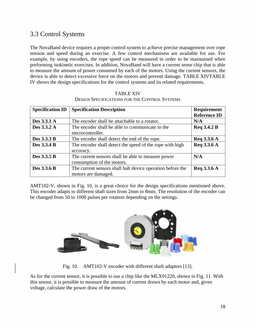
AMT102-V, shown in Fig. 10, is a great choice for the design specifications mentioned above.
This encoder adapts to different shaft sizes from 2mm to 8mm. The resolution of the encoder can
be changed from 50 to 1000 pulses per rotation depending on the settings.
Fig. 10. AMT102-V encoder with different shaft adapters [13].
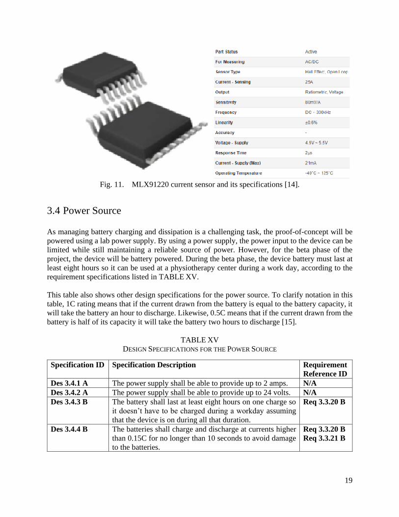
As for the current sensor, it is possible to use a chip like the MLX91220, shown in Fig. 11. With
this sensor, it is possible to measure the amount of current drawn by each motor and, given
voltage, calculate the power draw of the motors.
19
Fig. 11. MLX91220 current sensor and its specifications [14].
3.4 Power Source
As managing battery charging and dissipation is a challenging task, the proof-of-concept will be
powered using a lab power supply. By using a power supply, the power input to the device can be
limited while still maintaining a reliable source of power. However, for the beta phase of the
project, the device will be battery powered. During the beta phase, the device battery must last at
least eight hours so it can be used at a physiotherapy center during a work day, according to the
requirement specifications listed in TABLE XV.
This table also shows other design specifications for the power source. To clarify notation in this
table, 1C rating means that if the current drawn from the battery is equal to the battery capacity, it
will take the battery an hour to discharge. Likewise, 0.5C means that if the current drawn from the
battery is half of its capacity it will take the battery two hours to discharge [15].
TABLE XV
DESIGN SPECIFICATIONS FOR THE POWER SOURCE
Specification ID Specification Description Requirement
Reference ID
Des 3.4.1 A The power supply shall be able to provide up to 2 amps. N/A
Des 3.4.2 A The power supply shall be able to provide up to 24 volts. N/A
Des 3.4.3 B The battery shall last at least eight hours on one charge so
it doesn’t have to be charged during a workday assuming
that the device is on during all that duration.
Req 3.3.20 B
Des 3.4.4 B The batteries shall charge and discharge at currents higher
than 0.15C for no longer than 10 seconds to avoid damage
to the batteries.
Req 3.3.20 B
Req 3.3.21 B

20
4. Software
All mechanical and electronic components of the product are controlled through software.
Specifically, a mobile application communicating with a Bluetooth module attached to the device’s
microcontroller is the chosen method of control.
4.1 Physiotherapist-to-Device Interface
This section describes the design choices that relate to how a physiotherapist interacts with the
NovaBand device and how the user input is captured and transmitted to the device.
4.1.1 Mobile Application
NovaBand is intended to be precisely controlled by a physiotherapist to optimize the rehabilitation
routine of their patients. To meet this requirement, a physiotherapist needs an effective interface
to dynamically configure the device state.
The leading interface candidate is a custom mobile app. Apps are commonplace nowadays,
meaning that new apps can present an easier learning curve for a user than more traditional
hardware-based controls due to the significant transfer of previously learned knowledge.
Importantly, apps offer significant customizability with their ability to be altered via software
updates. Lastly, mobile apps are inherently portable; physiotherapists are afforded the flexibility
of operating the device from a comfortable distance.
TABLE XVI outlines the design specifications for the NovaBand mobile app. For the proof-of-
concept, the app shall be able to configure the tension or speed of the exercise on the NovaBand
device. Arguably, this is the most important feature to implement as all other configurations rely
on a reliable mechanism for updating the device tension settings.
The beta stage of development and onward present unknown challenges. Beta stage specifications
are shown in latter rows of TABLE XVI. It is expected that by the end of the beta stage,
physiotherapists shall be able to change exercises, receive notifications, and manage patient-
specific profiles. The exact implementation details of these features are not fully understood as of
now, but early progress indicates that each feature is likely achievable using the current
development technology. For instance, creating a simple list of preset exercises and allowing the
physiotherapist to select one of them fulfills most of the functionality required to change exercises
dynamically. Push notifications or on-screen textboxes can serve as general notification messages.
Lastly, using a simple database on the physiotherapist’s phone may be a sufficient means to save
and retrieve multiple patient profiles.
21
TABLE XVI
DESIGN SPECIFICATIONS FOR MOBILE APP
Specification ID Specification Description Requirement
Reference ID
Des 4.1.1 A The app shall allow the user to change tension required for
an exercise.
Req 3.1.1 A
Req 3.4.1 A
Des 4.1.2 A The app shall allow the user to change the type of exercise
being performed.
Req 3.1.1 A
Req 3.4.1 A
Des 4.1.3 A The app shall allow the user to change speed for an
exercise.
Req 3.1.1 A
Req 3.4.1 A
Des 4.1.4 B The app shall notify the user when an exercise is in
progress.
Req 3.4.1 A
Req 3.4.2 B
Des 4.1.5 B The app shall allow users to switch profiles and access their
saved exercises.
N/A
4.1.2 Data Transmission
For the mobile app to send data to the device, a data transmission protocol is required. An ideal
protocol must be simple to use, low latency, consume minimal power, and have a medium-long
communications range. It is noted that not all desired characteristics are explicitly listed in the
product’s requirements specifications document for various reasons. However, Bluetooth is one
such protocol that has these characteristics.
The Bluetooth protocol operates by establishing device-to-device trust using a pairing process,
which permits communication between bonded devices [16]. This pairing process can be
completed quickly via a phone user interface and without knowledge of the internal workings of
the protocol, fulfilling the requirement of the protocol being easy to use.
Continuing, TABLE XVII lists relevant technical specifications for Bluetooth Low Energy, a
feature supported by Bluetooth version 4.0 and newer, which consumes considerably less energy
than the previous (“classic”) versions of Bluetooth [17]. Based on the latency, power, and range
specifications listed in TABLE XVII, combined with the simplicity of pairing Bluetooth devices,
Bluetooth 4.0 is the leading choice for the required data transmission protocol.
TABLE XVII
TECHNICAL SPECIFICATIONS FOR BLUETOOTH LOW ENERGY [18]
Technical Specification Value for Bluetooth Low Energy
Range Less than 100m
Over air data rate Up to 2Mbit/s
Latency 6ms
Power Consumption 0.01W – 0.50W
Peak Current Consumption Less than 15mA
22
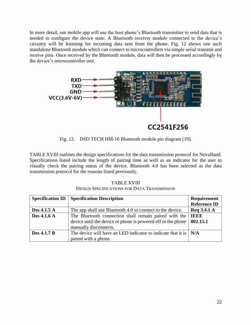
In more detail, our mobile app will use the host phone’s Bluetooth transmitter to send data that is
needed to configure the device state. A Bluetooth receiver module connected to the device’s
circuitry will be listening for incoming data sent from the phone. Fig. 12 shows one such
standalone Bluetooth module which can connect to microcontrollers via simple serial transmit and
receive pins. Once received by the Bluetooth module, data will then be processed accordingly by
the device’s microcontroller unit.
Fig. 12. DSD TECH HM-10 Bluetooth module pin diagram [19].
TABLE XVIII outlines the design specifications for the data transmission protocol for NovaBand.
Specifications listed include the length of pairing time as well as an indicator for the user to
visually check the pairing status of the device. Bluetooth 4.0 has been selected as the data
transmission protocol for the reasons listed previously.
TABLE XVIII
DESIGN SPECIFICATIONS FOR DATA TRANSMISSION
Specification ID Specification Description Requirement
Reference ID
Des 4.1.5 A The app shall use Bluetooth 4.0 to connect to the device. Req 3.4.1 A
Des 4.1.6 A The Bluetooth connection shall remain paired with the
device until the device or phone is powered off or the phone
manually disconnects.
IEEE
802.15.1
Des 4.1.7 B The device will have an LED indicator to indicate that it is
paired with a phone.
N/A
23
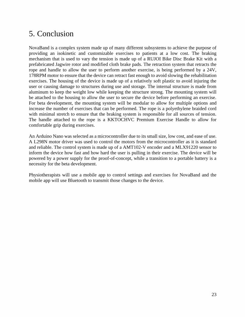
5. Conclusion
NovaBand is a complex system made up of many different subsystems to achieve the purpose of
providing an isokinetic and customizable exercises to patients at a low cost. The braking
mechanism that is used to vary the tension is made up of a RUJOI Bike Disc Brake Kit with a
prefabricated Jagwire rotor and modified cloth brake pads. The retraction system that retracts the
rope and handle to allow the user to perform another exercise, is being performed by a 24V,
178RPM motor to ensure that the device can retract fast enough to avoid slowing the rehabilitation
exercises. The housing of the device is made up of a relatively soft plastic to avoid injuring the
user or causing damage to structures during use and storage. The internal structure is made from
aluminum to keep the weight low while keeping the structure strong. The mounting system will
be attached to the housing to allow the user to secure the device before performing an exercise.
For beta development, the mounting system will be modular to allow for multiple options and
increase the number of exercises that can be performed. The rope is a polyethylene braided cord
with minimal stretch to ensure that the braking system is responsible for all sources of tension.
The handle attached to the rope is a KKTOCHVC Premium Exercise Handle to allow for
comfortable grip during exercises.
An Arduino Nano was selected as a microcontroller due to its small size, low cost, and ease of use.
A L298N motor driver was used to control the motors from the microcontroller as it is standard
and reliable. The control system is made up of a AMT102-V encoder and a MLX91220 sensor to
inform the device how fast and how hard the user is pulling in their exercise. The device will be
powered by a power supply for the proof-of-concept, while a transition to a portable battery is a
necessity for the beta development.
Physiotherapists will use a mobile app to control settings and exercises for NovaBand and the
mobile app will use Bluetooth to transmit those changes to the device.

24
References
[1] R. Allain, "Do Rubber Bands Act Like Springs?," WIRED, 08 August 2012. [Online].
Available: https://www.wired.com/2012/08/do-rubber-bands-act-like-springs/. [Accessed
20 February 2021].
[2] F. Guenzkofer, H. Bubb and K. Bengler, "Maximum elbow joint torques for digital human
models," International Journal of Human Factors Modelling and Simulation, vol. III, no.
2, pp. 109-132, 2021.
[3] A. Hamilton, "Sports Injury Bulletin," [Online]. Available:
https://www.sportsinjurybulletin.com/smooth-movement-the-benefits-of-isokinetic-
training/. [Accessed 22 March 2021].
[4] Biodex, "System 4 Pro™ - Dynamometers - Physical Medicine | Biodex," Biodex.com,
[Online]. Available: https://www.biodex.com/physical-
medicine/products/dynamometers/system-4-pro. [Accessed 10 March 2021].
[5] N. Zarzycka and S. Załuska, "Measurements of the forearm in inhabitants of the Lublin
region," Ann Univ Mariae Curie Sklodowska Med, vol. 44, pp. 85-92, 1989.
[6] Amazon.com, "RUJOI Bike Disc Brake Kit, Aluminum Front and Rear Caliper, Full
Aluminum Alloy Bicycle Brake Lever, 160mm Rotor, Mechanic Tool-Free Pad Adjuster
for Road Bike, Mountain Bike," Amazon.com, 2 August 2019. [Online]. Available:
https://www.amazon.com/RUJOI-Aluminum-Mechanic-Tool-Free-
Adjuster/dp/B08R3ML6T1?th=1. [Accessed 24 March 2021].
[7] C. Oertel, H. Neuburger and A. Sabo, "Construction of a test bench for bicycle rim and
disc brakes," Procedia Engineering, vol. 2, pp. 2943-2948, 2010.
[8] CanadaBicycleParts, "JAGWIRE LR1 PRO LIGHTWEIGH ROTOR,"
CanadaBicycleParts, 26 June 2018. [Online]. Available:
https://www.canadabicycleparts.com/jagwire-lr1-pro-lightweigh-rotor-13679. [Accessed
25 March 2021].
[9] Amazon.com, "emma kites UHMWPE Braided Cord High Strength Least Stretch Tent
Tarp Rain Fly Guyline Hammock Ridgeline Suspension for Camping Hiking Backpacking
Survival Recreational Marine Outdoors," Amazon.com, 29 March 2018. [Online].
Available:
https://www.amazon.ca/gp/product/B07BKSJFJ8/ref=ppx_yo_dt_b_asin_title_o04_s00?ie
=UTF8&th=1&psc=1. [Accessed 24 March 2021].
[10] LIFT-IT, "Samson Rope Information Sheet," LIFT-IT, 5 October 2012. [Online].
Available: https://www.lift-it.com/info-rope-use-inspection#. [Accessed 24 March 2021].
[11] Ardunio, "ARDUINO NANO," Ardunio, [Online]. Available:
https://store.arduino.cc/usa/arduino-nano. [Accessed 23 February 2021].
[12] Amazon.com, "Akozon Motor Driver 1pc L298N Module H Bridge Driver Board Module
for Stepper Motor Smart Car Robot," Akozon, [Online]. Available:
https://www.amazon.ca/Akozon-Module-Bridge-Driver-
Stepper/dp/B07GC26TVK/ref=sr_1_1_sspa?dchild=1&keywords=ld298+motor+driver&q
id=1616798480&sr=8-1-

25
spons&psc=1&spLa=ZW5jcnlwdGVkUXVhbGlmaWVyPUFMNFRVQ1pMQjdETFEmZ
W5jcnlwdGVkSWQ9QTAyNTk1OTkxMzlNSE42ME4yODdOJmV.
[13] Digikey, "AMT102-V," CUI Devices, [Online]. Available:
https://www.digikey.ca/en/products/detail/cui-devices/AMT102-
V/827015?utm_adgroup=Sensors%2C%20Transducers&utm_source=google&utm_mediu
m=cpc&utm_campaign=Smart%20Shopping_Product_Sensors%2C%20Transducers&utm
_term=&productid=827015&gclid=Cj0KCQjwjPaCBhDkARI.
[14] Digikey, "MLX91220KDF-ABF-025-RE," Melexis Technologies NV, [Online].
Available: https://www.digikey.ca/en/products/detail/melexis-technologies-
nv/MLX91220KDF-ABF-025-RE/11617705.
[15] Battery university , "BU-402: What Is C-rate?," 9 3 2017. [Online]. Available:
https://batteryuniversity.com/learn/article/what_is_the_c_rate#:~:text=Charge%20and%20
discharge%20rates%20of,delivers%202A%20for%2030%20minutes..
[16] Android Developers, "Bluetooth overview," 2021. [Online]. Available:
https://developer.android.com/guide/topics/connectivity/bluetooth. [Accessed 25 March
2021].
[17] Android Developers, "Bluetooth Low Energy," Android, 08 March 2021. [Online].
Available: https://developer.android.com/guide/topics/connectivity/bluetooth-le.
[Accessed 24 March 2021].
[18] Wikipedia, "Bluetooth Low Energy," [Online]. Available:
https://en.wikipedia.org/wiki/Bluetooth_Low_Energy. [Accessed 24 March 2021].
[19] Amazon, "DSD TECH HM-10 Bluetooth 4.0 BLE iBeacon UART Module with 4PIN
Base Board for Arduino UNO R3 Mega 2560 Nano," [Online]. Available:
https://www.amazon.ca/DSD-TECH-Bluetooth-iBeacon-
Arduino/dp/B06WGZB2N4/ref=sr_1_5?dchild=1&keywords=Arduino+Bluetooth&qid=1
616647292&sr=8-5. [Accessed 24 March 2021].
[20] Amazon.com, "WINOMO Pack of Disc Brake Front Rear Disc Rotor Brake Kit for MTB
Bicycle(F180/R160," Amazon.com, 7 March 2018. [Online]. Available:
https://www.amazon.ca/gp/product/B079P6SZLY. [Accessed 23 March 2021].
[21] Walmart, "2pcs Bike MTB Mechanical Disc Brake Kit Front and Rear Brake WIth G2
Rotors Set for Mountain Bicycle-160mm," Walmart, 23 March 2021. [Online]. Available:
https://www.walmart.ca/en/ip/2pcs-Bike-MTB-Mechanical-Disc-Brake-Kit-Front-and-
Rear-Brake-WIth-G2-Rotors-Set-for-Mountain-Bicycle-160mm/PRD43PEG24TBVG4.
[Accessed 25 March 2021].
[22] Amazon.com, "1 Pair Bicycle Brake Fine Paint Aluminum Alloy Hydraulic Disc Brakes
Front Rear Oil Pressure Bike Braking for MTB Road Bike 4 Colors Optional,"
Amazon.com, 5 August 2019. [Online]. Available: https://www.amazon.ca/Bicycle-
Aluminum-Hydraulic-Pressure-Optional/dp/B07W1HWFDL/. [Accessed 24 March 2021].
[23] Amazon.com, "USDREAM Hydraulic Disc Brakes Mountain Bike Sets MTB
800/1400mm Hydraulic Bicycle Front/Rear Oil Pressure Braking Kit," Amazon.com, 2
March 2019. [Online]. Available: https://www.amazon.ca/USDREAM-Hydraulic-
Mountain-Bicycle-Pressure/dp/B07PLXK47C/. [Accessed 23 March 2021].
26
[24] CanadaBicycleParts, "SHIMANO BR-UR300 DISC BRAKE," CanadaBicycleParts,
[Online]. Available: https://www.canadabicycleparts.com/shimano-br-ur300-disc-brake-
22130. [Accessed 23 March 2021].
[25] Chetvorno, "Eddy current brake diagram," 13 June 2015. [Online]. Available:
https://commons.wikimedia.org/wiki/File:Eddy_current_brake_diagram.svg. [Accessed 24
March 2021].
[26] Amazon.com, "4 Pairs Resin Bike Bicycle Disc Brake Pads for TRP Tektro Shimano
Deore Br-M575 M525 M515 T615 T675 M505 M495 M486 M485 M475 M465 M447
M446 M445 M416 M415 M395 M375 M315 M355 C601 C501," Amazon.com, 16
October 2019. [Online]. Available: https://www.amazon.ca/Magitati-Bicycle-Tektro-
Shimano-Br-M575/dp/B07Z3KBMYT/. [Accessed 26 March 2021].
[27] Amazon.com, "AHL 4pairs Bicycle Disc Brake Pads for Shimano M375 M395 M486
M485 M475 M416 M446 M515 M445 M525 for Tektro Aquila/Auriga
Pro/Gemini/Draco," Amazon.com, 18 August 2016. [Online]. Available:
https://www.amazon.ca/AHL-4pairs-Bicycle-Shimano-Tektro/dp/B01AHP55IY/.
[Accessed 25 March 2021].
[28] Amazon.com, "corki 140mm 160mm 180mm 203mm Bike Disc Brake Rotor with 6 Bolts
Fit for Road Bike,Mountain Bike,MTB,BMX," Amazon.com, 27 February 2020. [Online].
Available: https://www.amazon.ca/corki-140mm-160mm-180mm-
Mountain/dp/B082STJD1F/. [Accessed 24 March 2021].
[29] Robotshop, "GM37 Geared Motor with encoder - 24V 178RPM," ES-Motors, [Online].
Available: https://www.robotshop.com/ca/en/gm37-geared-motor-with-encoder-24v-
178rpm.html.
[30] Animalia life, "Photo Gallery of - Retractable Dog Leash Mechanism," [Online].
Available: http://www.animalia-life.club/other/retractable-dog-leash-mechanism.html.
[31] The Home Depot, "Types of Rope," The Home Depot, 20 November 2020. [Online].
Available: https://www.homedepot.com/c/ab/types-of-
rope/9ba683603be9fa5395fab9020598ae9. [Accessed 23 March 2021].
[32] Quality Nylon Rope, "Everything You Need To Know About Rope And Cord Stretching,"
Quality Nylon Rope, 6 January 2016. [Online]. Available:
https://www.qualitynylonrope.com/blog/everything-you-need-to-know-about-rope-and-
cord-stretching-/. [Accessed 23 March 2021].
[33] QC SUPPLY, "No Stretch Rope - 1000 Ft," QC SUPPLY, 16 August 2010. [Online].
Available: https://www.qcsupply.com/90450-no-stretch-rope.html. [Accessed 24 March
2021].
[34] Amazon.com, "emma kites 100% Braided Kevlar String Black High Tensile for Outdoor
Activities, Tactical, Survival and Other General Purpose," Amazon.com, 25 October 2016.
[Online]. Available: https://www.amazon.ca/emma-kites-Activities-Tactical-
Survival/dp/B01AZBIOR4/?th=1&psc=1. [Accessed 24 March 2021].
[35] Amazon.com, "emma kites UHMWPE Braided Cord High Strength Least Stretch Tent
Tarp Rain Fly Guyline Hammock Ridgeline Suspension for Camping Hiking Backpacking
Survival Recreational Marine Outdoors," Amazon.com, 29 March 2018. [Online].
Available: https://www.amazon.ca/gp/product/B07BKSJFJ8/?th=1&psc=1. [Accessed 24
March 2021].
27
[36] Amazon, "KKTOCHVC Premium Exercise Pull Handles Resistance Bands Foam Updated
Handle Replacement Fitness Equipment for Pilates, Yoga, Strength Training,"
Amazon.com, [Online]. Available: https://www.amazon.ca/KKTech-Resistance-
Replacement-Equipment-
Training%EF%BC%88/dp/B01JKVRKKW/ref=sr_1_11?dchild=1&keywords=resistance
+band+handle&qid=1616816500&sr=8-11. [Accessed 26 March 2021].
[37] Amazon, "GoFit Adjustable Neoprene Ankle Strap - Black Extreme Tube/Band,"
Amazon.com, [Online]. Available: https://www.amazon.ca/GoFit-Carabiner-Rubber-
Resistance-
Training/dp/B0091MBGTC/ref=sr_1_49?crid=25J95011D06TX&dchild=1&keywords=re
sistance+band+handles+with+foot&qid=1616816821&sprefix=resistance+band+foot+han
dle%2Caps%2C231&sr=8-49. [Accessed 26 March 2021].
[38] Raspberry Pi Foundation, "Raspberry Pi Zero," Raspberry Pi Foundation, [Online].
Available: https://www.raspberrypi.org/products/raspberry-pi-zero/. [Accessed 23
February 2021].
[39] N. Dahl, "What Is an H-Bridge?," [Online]. Available: https://www.build-electronic-
circuits.com/h-bridge/.
[40] Digikey, "CR9321-PNP," CR Magnetics Inc, [Online]. Available:
https://www.digikey.ca/en/products/detail/cr-magnetics-inc/CR9321-PNP/1045178.
[41] D. Thomas, E. Wilkie and J. Irvine, "Comparison of Power Consumption of WiFi Inbuilt
Internet of Things Device with Bluetooth Low Energy," International Journal of
Computer and Information Engineering, vol. 10, no. 10, p. 1856, 2016.
[42] Zigbee Alliance, "Zigbee," Zigbee Alliance, [Online]. Available:
https://zigbeealliance.org/solution/zigbee/. [Accessed 26 03 2021].
[43] "Sliding Filament Theory," The University of Sheffield, 2011. [Online]. Available:
https://slidingfilament.webnode.com/applications/length-tension-relationship/. [Accessed
20 February 2021].
[44] Theraband, "Theraband Professional Latex Resistance Band Loop," [Online]. Available:
https://www.theraband.com/theraband-professional-latex-resistance-band-loops.html.
[45] Amazon.com, "RUJOI Bike Disc Brake Kit, Aluminum Front and Rear Caliper, Full
Aluminum Alloy Bicycle Brake Lever, 160mm Rotor, Mechanic Tool-Free Pad Adjuster
for Road Bike, Mountain Bike," Amazon.com, 23 April 2019. [Online]. Available:
https://www.amazon.ca/gp/product/B07TW7H3GX/ref=ppx_yo_dt_b_asin_title_o03_s00
?ie=UTF8&psc=1. [Accessed 23 March 2021].
[46] Amazon.com, "RUJOI Bike Disc Brake Kit, Aluminum Front and Rear Caliper, Full
Aluminum Alloy Bicycle Brake Lever, 160mm Rotor, Mechanic Tool-Free Pad Adjuster
for Road Bike, Mountain Bike," Amazon.com, 2 August 2019. [Online]. Available:
https://www.amazon.com/RUJOI-Aluminum-Mechanic-Tool-Free-
Adjuster/dp/B08RHX6G32/?th=1. [Accessed 25 March 2021].
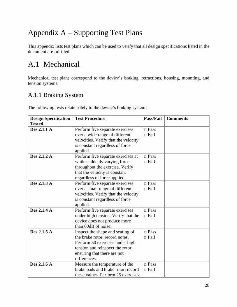
28
Appendix A – Supporting Test Plans
This appendix lists test plans which can be used to verify that all design specifications listed in the
document are fulfilled.
A.1 Mechanical
Mechanical test plans correspond to the device’s braking, retractions, housing, mounting, and
tension systems.
A.1.1 Braking System
The following tests relate solely to the device’s braking system:
Design Specification
Tested
Test Procedure Pass/Fail Comments
Des 2.1.1 A Perform five separate exercises
over a wide range of different
velocities. Verify that the velocity
is constant regardless of force
applied.
□ Pass
□ Fail
Des 2.1.2 A Perform five separate exercises at
while suddenly varying force
throughout the exercise. Verify
that the velocity is constant
regardless of force applied.
□ Pass
□ Fail
Des 2.1.3 A Perform five separate exercises
over a small range of different
velocities. Verify that the velocity
is constant regardless of force
applied.
□ Pass
□ Fail
Des 2.1.4 A Perform five separate exercises
under high tension. Verify that the
device does not produce more
than 60dB of noise.
□ Pass
□ Fail
Des 2.1.5 A Inspect the shape and seating of
the brake rotor, record notes.
Perform 50 exercises under high
tension and reinspect the rotor,
ensuring that there are not
differences.
□ Pass
□ Fail
Des 2.1.6 A Measure the temperature of the
brake pads and brake rotor, record
these values. Perform 25 exercises
□ Pass
□ Fail

29
at high tension, record the final
temperature of the rotor. Ensure
that the temperature does not
exceed 52℃.
Des 2.1.6 A Perform one rep at high tension to
verify function of the device.
Perform 25 more exercises and
then reperform a rep at high
tension. Verify that the velocity is
constant throughout the exercise.
□ Pass
□ Fail
A.1.2 Retraction System
The following tests relate to the device’s retraction system:
Design Specification
Tested
Test Procedure Pass/Fail Comments
Des 2.2.1 A Perform an exercise and allow the
system to retract. As it is
retracting, pull on the rope and
ensure it stops retracting.
□ Pass
□ Fail
Des 2.2.2 A
Des 2.2.3 A
Perform an exercise and release
the handle. Ensure that the handle
begins to retract and does not
retract faster than 0.3m/s.
□ Pass
□ Fail
A.1.3 Housing, Materials, and Layout
The following tests relate to the device’s housing, materials, and layout:
Design Specification
Tested
Test Procedure Pass/Fail Comments
Des 2.3.1 A Physically inspect the device and
attempt to open it at the seams.
Ensure that none of the
components can be accessed.
□ Pass
□ Fail
Des 2.3.8 B
Lift the device to one meter of
elevation and drop it. Ensure the
device did not sustain any
significant damage.
□ Pass
□ Fail
Des 2.3.9 B
Change settings of an exercise.
Ensure that the settings were
changed.
□ Pass
□ Fail

30
A.1.4 Mounting System
The following tests relate to the device’s mounting system:
Design Specification
Tested
Test Procedure Pass/Fail Comments
Des 2.4.2 B Detach the existing mounting
system, attach a different module,
and ensure that the module locks
in place. Mount the device,
perform an exercise, and ensure
that the device is securely
mounted
□ Pass
□ Fail
A.1.5 Tension System
The following tests relate to the device’s tension system:
Design Specification
Tested
Test Procedure Pass/Fail Comments
Des 2.5.1 A Perform a maximum resistance
exercise. Ensure that the rope does
not break or strain.
□ Pass
□ Fail
Des 2.5.2 B Stretch the rope manually.
Measure the stretch and ensure it
remains under 4.5%.
□ Pass
□ Fail
Des 2.5.3 B Stretch the rope and rub it against
an abrasive surface. Ensure the
rope does not sustain any
structural damage.
□ Pass
□ Fail
A.2 Electronics
The electronics test plans correspond to the device’s force and distance sensors, as well as the
encoders.
A.2.1 Microcontroller
The following tests relate to the device’s microcontroller:
Design Specification
Tested
Test Procedure Pass/Fail Comments
Des 3.1.1 A
Des 3.1.3 A
Perform an exercise with a set
speed. Perform an exercise with a
□ Pass
□ Fail
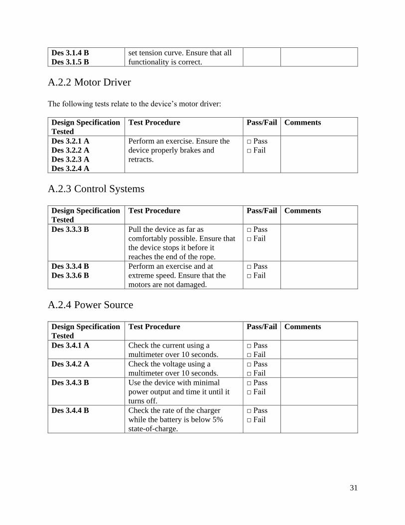
31
Des 3.1.4 B
Des 3.1.5 B
set tension curve. Ensure that all
functionality is correct.
A.2.2 Motor Driver
The following tests relate to the device’s motor driver:
Design Specification
Tested
Test Procedure Pass/Fail Comments
Des 3.2.1 A
Des 3.2.2 A
Des 3.2.3 A
Des 3.2.4 A
Perform an exercise. Ensure the
device properly brakes and
retracts.
□ Pass
□ Fail
A.2.3 Control Systems
Design Specification
Tested
Test Procedure Pass/Fail Comments
Des 3.3.3 B Pull the device as far as
comfortably possible. Ensure that
the device stops it before it
reaches the end of the rope.
□ Pass
□ Fail
Des 3.3.4 B
Des 3.3.6 B
Perform an exercise and at
extreme speed. Ensure that the
motors are not damaged.
□ Pass
□ Fail
A.2.4 Power Source
Design Specification
Tested
Test Procedure Pass/Fail Comments
Des 3.4.1 A Check the current using a
multimeter over 10 seconds.
□ Pass
□ Fail
Des 3.4.2 A Check the voltage using a
multimeter over 10 seconds.
□ Pass
□ Fail
Des 3.4.3 B Use the device with minimal
power output and time it until it
turns off.
□ Pass
□ Fail
Des 3.4.4 B Check the rate of the charger
while the battery is below 5%
state-of-charge.
□ Pass
□ Fail
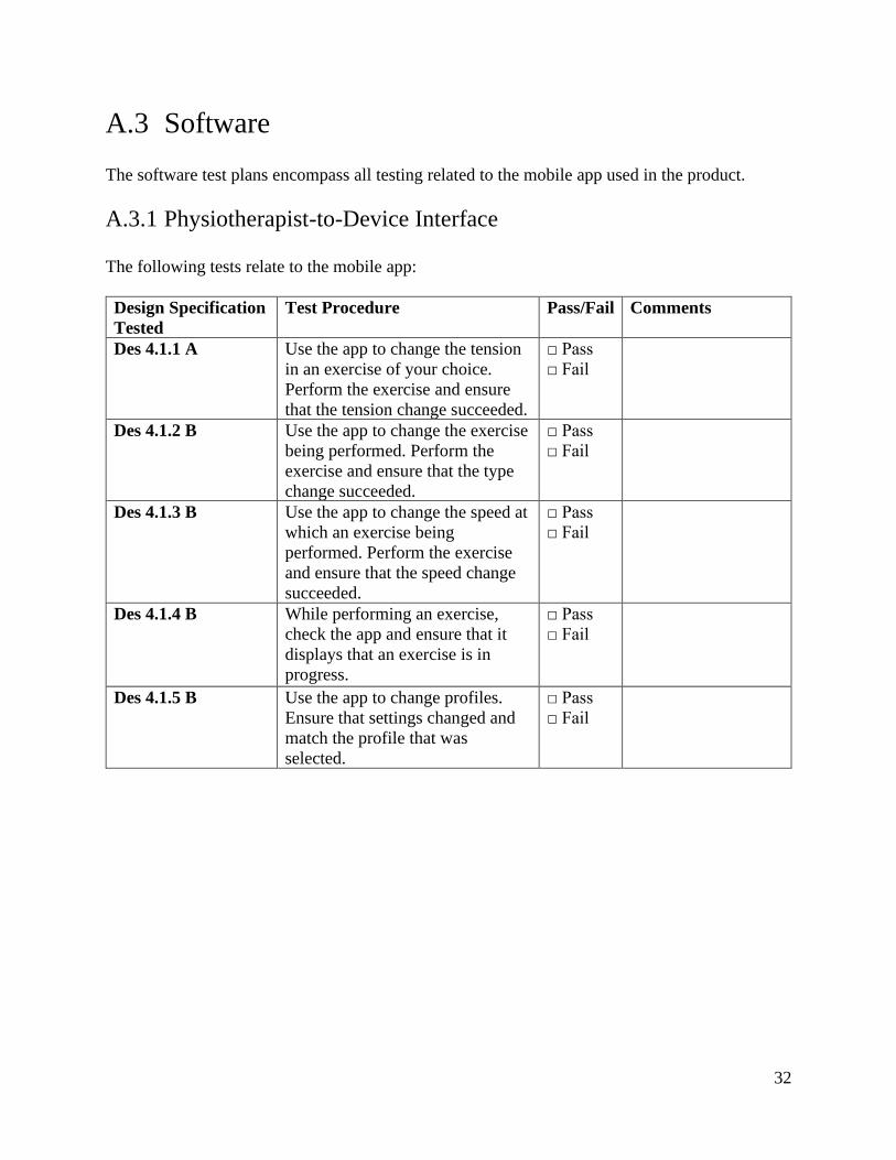
32
A.3 Software
The software test plans encompass all testing related to the mobile app used in the product.
A.3.1 Physiotherapist-to-Device Interface
The following tests relate to the mobile app:
Design Specification
Tested
Test Procedure Pass/Fail Comments
Des 4.1.1 A Use the app to change the tension
in an exercise of your choice.
Perform the exercise and ensure
that the tension change succeeded.
□ Pass
□ Fail
Des 4.1.2 B Use the app to change the exercise
being performed. Perform the
exercise and ensure that the type
change succeeded.
□ Pass
□ Fail
Des 4.1.3 B Use the app to change the speed at
which an exercise being
performed. Perform the exercise
and ensure that the speed change
succeeded.
□ Pass
□ Fail
Des 4.1.4 B While performing an exercise,
check the app and ensure that it
displays that an exercise is in
progress.
□ Pass
□ Fail
Des 4.1.5 B Use the app to change profiles.
Ensure that settings changed and
match the profile that was
selected.
□ Pass
□ Fail

33
Appendix B – Supporting Design Options
B.1 Mechanical B.1.1 Braking System
B.1.1.1 Braking Mechanism
Mechanical Bicycle Disc Brake
The most common type of bicycle disc brake is mechanical – a lever arm pressed by the rider pulls
on a steel cable attached to a clamp, which closes onto a metal disc, which is in turn attached to
the wheel. Any commercially available disc brake would provide more than enough braking force
[7], but might not necessarily have enough high-enough fidelity at the relatively low forces of this
application. Mechanical brakes have the advantage of being actuated by a simple lever, which is
inherently easy to actuate with the axle of a motor. Mechanical disc brakes are also usually much
cheaper than other options, though the cheapest end of hydraulic brakes do come close. Product
options for mechanical disc brakes are given in TABLE XIX.
TABLE XIX
PRODUCT OPTIONS FOR MECHANICAL DISC BRAKES
Product Name Description
RUJOI Bike Disc Brake
Kit [6]
Price $45.99
Rotor Material Stainless steel rotors
Rotor Diameter 160mm
Configuration Front and rear
Misc. Includes handles and cable
WINOMO Pack of Disc
Brake [20]
Price $20.32
Rotor Material Aluminum
Rotor Diameter 160mm
Configuration Front and rear
Misc.
2pcs Bike MTB
Mechanical Disc Brake
Kit [21]
Price $28.93
Rotor Material Stainless steel
Rotor Diameter 160mm
Configuration Front and rear brakes
Misc.
Hydraulic Bicycle Disc Brake
Hydraulic brakes operate by way of a closed line of hydraulic fluid connected on one end to a
piston that is compressed by the handle and on the other to a pair of calipers. This closed hydraulic
line provides a much more consistent and smooth modulation of the braking force (which is
desirable), but would require a linear actuator or a complicated and custom mechanism to convert
from rotary motion to rotational to actuate the line’s piston. Luckily, there exists a hybrid: cable
actuated hydraulic disc brakes. For NovaBand, these combine the best of mechanical and hydraulic
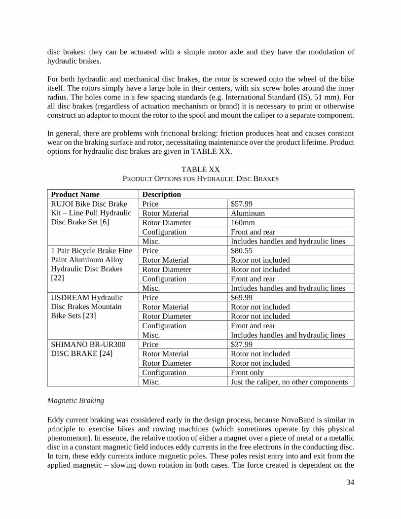
34
disc brakes: they can be actuated with a simple motor axle and they have the modulation of
hydraulic brakes.
For both hydraulic and mechanical disc brakes, the rotor is screwed onto the wheel of the bike
itself. The rotors simply have a large hole in their centers, with six screw holes around the inner
radius. The holes come in a few spacing standards (e.g. International Standard (IS), 51 mm). For
all disc brakes (regardless of actuation mechanism or brand) it is necessary to print or otherwise
construct an adaptor to mount the rotor to the spool and mount the caliper to a separate component.
In general, there are problems with frictional braking: friction produces heat and causes constant
wear on the braking surface and rotor, necessitating maintenance over the product lifetime. Product
options for hydraulic disc brakes are given in TABLE XX.
TABLE XX
PRODUCT OPTIONS FOR HYDRAULIC DISC BRAKES
Product Name Description
RUJOI Bike Disc Brake
Kit – Line Pull Hydraulic
Disc Brake Set [6]
Price $57.99
Rotor Material Aluminum
Rotor Diameter 160mm
Configuration Front and rear
Misc. Includes handles and hydraulic lines
1 Pair Bicycle Brake Fine
Paint Aluminum Alloy
Hydraulic Disc Brakes
[22]
Price $80.55
Rotor Material Rotor not included
Rotor Diameter Rotor not included
Configuration Front and rear
Misc. Includes handles and hydraulic lines
USDREAM Hydraulic
Disc Brakes Mountain
Bike Sets [23]
Price $69.99
Rotor Material Rotor not included
Rotor Diameter Rotor not included
Configuration Front and rear
Misc. Includes handles and hydraulic lines
SHIMANO BR-UR300
DISC BRAKE [24]
Price $37.99
Rotor Material Rotor not included
Rotor Diameter Rotor not included
Configuration Front only
Misc. Just the caliper, no other components
Magnetic Braking
Eddy current braking was considered early in the design process, because NovaBand is similar in
principle to exercise bikes and rowing machines (which sometimes operate by this physical
phenomenon). In essence, the relative motion of either a magnet over a piece of metal or a metallic
disc in a constant magnetic field induces eddy currents in the free electrons in the conducting disc.
In turn, these eddy currents induce magnetic poles. These poles resist entry into and exit from the
applied magnetic – slowing down rotation in both cases. The force created is dependent on the
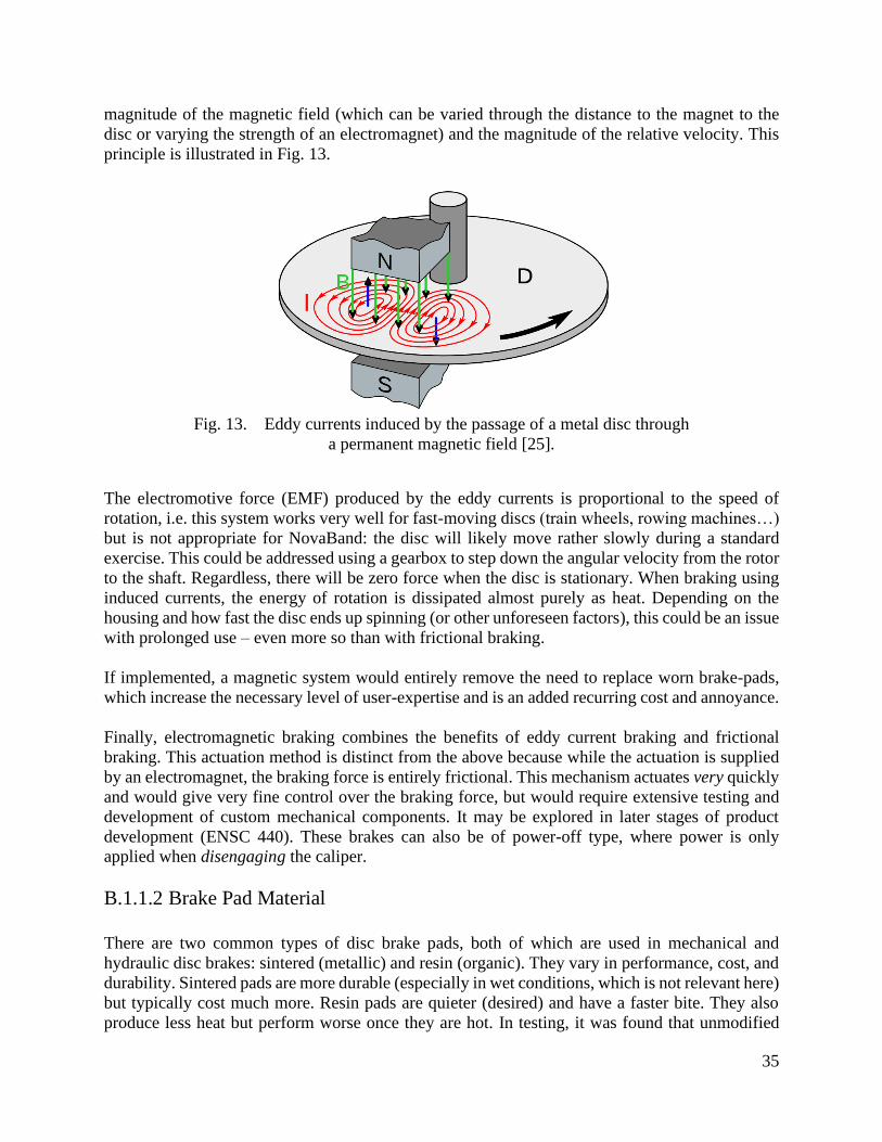
35
magnitude of the magnetic field (which can be varied through the distance to the magnet to the
disc or varying the strength of an electromagnet) and the magnitude of the relative velocity. This
principle is illustrated in Fig. 13.
Fig. 13. Eddy currents induced by the passage of a metal disc through
a permanent magnetic field [25].
The electromotive force (EMF) produced by the eddy currents is proportional to the speed of
rotation, i.e. this system works very well for fast-moving discs (train wheels, rowing machines…)
but is not appropriate for NovaBand: the disc will likely move rather slowly during a standard
exercise. This could be addressed using a gearbox to step down the angular velocity from the rotor
to the shaft. Regardless, there will be zero force when the disc is stationary. When braking using
induced currents, the energy of rotation is dissipated almost purely as heat. Depending on the
housing and how fast the disc ends up spinning (or other unforeseen factors), this could be an issue
with prolonged use – even more so than with frictional braking.
If implemented, a magnetic system would entirely remove the need to replace worn brake-pads,
which increase the necessary level of user-expertise and is an added recurring cost and annoyance.
Finally, electromagnetic braking combines the benefits of eddy current braking and frictional
braking. This actuation method is distinct from the above because while the actuation is supplied
by an electromagnet, the braking force is entirely frictional. This mechanism actuates very quickly
and would give very fine control over the braking force, but would require extensive testing and
development of custom mechanical components. It may be explored in later stages of product
development (ENSC 440). These brakes can also be of power-off type, where power is only
applied when disengaging the caliper.
B.1.1.2 Brake Pad Material
There are two common types of disc brake pads, both of which are used in mechanical and
hydraulic disc brakes: sintered (metallic) and resin (organic). They vary in performance, cost, and
durability. Sintered pads are more durable (especially in wet conditions, which is not relevant here)
but typically cost much more. Resin pads are quieter (desired) and have a faster bite. They also
produce less heat but perform worse once they are hot. In testing, it was found that unmodified
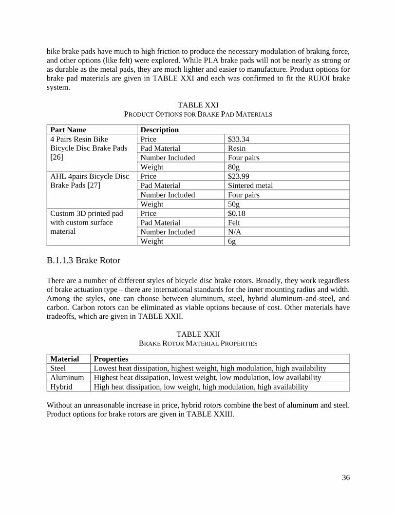
36
bike brake pads have much to high friction to produce the necessary modulation of braking force,
and other options (like felt) were explored. While PLA brake pads will not be nearly as strong or
as durable as the metal pads, they are much lighter and easier to manufacture. Product options for
brake pad materials are given in TABLE XXI and each was confirmed to fit the RUJOI brake
system.
TABLE XXI
PRODUCT OPTIONS FOR BRAKE PAD MATERIALS
Part Name Description
4 Pairs Resin Bike
Bicycle Disc Brake Pads
[26]
Price $33.34
Pad Material Resin
Number Included Four pairs
Weight 80g
AHL 4pairs Bicycle Disc
Brake Pads [27]
Price $23.99
Pad Material Sintered metal
Number Included Four pairs
Weight 50g
Custom 3D printed pad
with custom surface
material
Price $0.18
Pad Material Felt
Number Included N/A
Weight 6g
B.1.1.3 Brake Rotor
There are a number of different styles of bicycle disc brake rotors. Broadly, they work regardless
of brake actuation type – there are international standards for the inner mounting radius and width.
Among the styles, one can choose between aluminum, steel, hybrid aluminum-and-steel, and
carbon. Carbon rotors can be eliminated as viable options because of cost. Other materials have
tradeoffs, which are given in TABLE XXII.
TABLE XXII
BRAKE ROTOR MATERIAL PROPERTIES
Material Properties
Steel Lowest heat dissipation, highest weight, high modulation, high availability
Aluminum Highest heat dissipation, lowest weight, low modulation, low availability
Hybrid High heat dissipation, low weight, high modulation, high availability
Without an unreasonable increase in price, hybrid rotors combine the best of aluminum and steel.
Product options for brake rotors are given in TABLE XXIII.

37
TABLE XXIII
PRODUCT OPTIONS FOR THE BRAKE ROTOR
Part Name Description
JAGWIRE LR1 PRO
LIGHTWEIGH ROTOR
[8]
Price $64.99
Material Hybrid aluminum-and-steel
Number Included One
Diameter 140mm
Weight 80g
Corki Disc Brake Rotor
[28]
Price $44.99
Material Steel
Number Included Two
Diameter 140mm
Weight 100g
B.1.2 Retraction System
For the retraction system to be able to function, NovaBand must be able to retract the rope fully at
safe speeds specified by Req 3.3.12 B. There are a few ways that this can be achieved. TABLE
XXIV shows different choices for the retraction system.
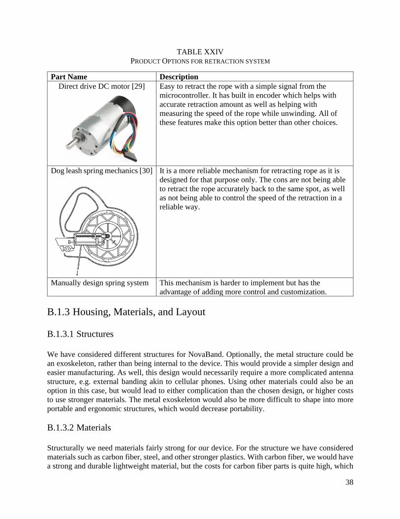
38
TABLE XXIV
PRODUCT OPTIONS FOR RETRACTION SYSTEM
Part Name Description
Direct drive DC motor [29]
Easy to retract the rope with a simple signal from the
microcontroller. It has built in encoder which helps with
accurate retraction amount as well as helping with
measuring the speed of the rope while unwinding. All of
these features make this option better than other choices.
Dog leash spring mechanics [30]
It is a more reliable mechanism for retracting rope as it is
designed for that purpose only. The cons are not being able
to retract the rope accurately back to the same spot, as well
as not being able to control the speed of the retraction in a
reliable way.
Manually design spring system This mechanism is harder to implement but has the
advantage of adding more control and customization.
B.1.3 Housing, Materials, and Layout
B.1.3.1 Structures
We have considered different structures for NovaBand. Optionally, the metal structure could be
an exoskeleton, rather than being internal to the device. This would provide a simpler design and
easier manufacturing. As well, this design would necessarily require a more complicated antenna
structure, e.g. external banding akin to cellular phones. Using other materials could also be an
option in this case, but would lead to either complication than the chosen design, or higher costs
to use stronger materials. The metal exoskeleton would also be more difficult to shape into more
portable and ergonomic structures, which would decrease portability.
B.1.3.2 Materials
Structurally we need materials fairly strong for our device. For the structure we have considered
materials such as carbon fiber, steel, and other stronger plastics. With carbon fiber, we would have
a strong and durable lightweight material, but the costs for carbon fiber parts is quite high, which
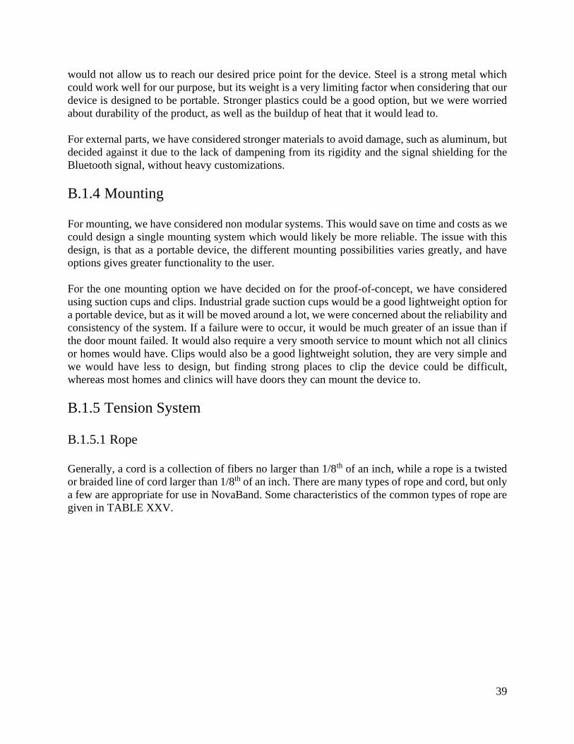
39
would not allow us to reach our desired price point for the device. Steel is a strong metal which
could work well for our purpose, but its weight is a very limiting factor when considering that our
device is designed to be portable. Stronger plastics could be a good option, but we were worried
about durability of the product, as well as the buildup of heat that it would lead to.
For external parts, we have considered stronger materials to avoid damage, such as aluminum, but
decided against it due to the lack of dampening from its rigidity and the signal shielding for the
Bluetooth signal, without heavy customizations.
B.1.4 Mounting
For mounting, we have considered non modular systems. This would save on time and costs as we
could design a single mounting system which would likely be more reliable. The issue with this
design, is that as a portable device, the different mounting possibilities varies greatly, and have
options gives greater functionality to the user.
For the one mounting option we have decided on for the proof-of-concept, we have considered
using suction cups and clips. Industrial grade suction cups would be a good lightweight option for
a portable device, but as it will be moved around a lot, we were concerned about the reliability and
consistency of the system. If a failure were to occur, it would be much greater of an issue than if
the door mount failed. It would also require a very smooth service to mount which not all clinics
or homes would have. Clips would also be a good lightweight solution, they are very simple and
we would have less to design, but finding strong places to clip the device could be difficult,
whereas most homes and clinics will have doors they can mount the device to.
B.1.5 Tension System
B.1.5.1 Rope
Generally, a cord is a collection of fibers no larger than 1/8th of an inch, while a rope is a twisted
or braided line of cord larger than 1/8th of an inch. There are many types of rope and cord, but only
a few are appropriate for use in NovaBand. Some characteristics of the common types of rope are
given in TABLE XXV.

40
TABLE XXV
CHARACTERISTICS OF COMMON TYPES OF LINES [31]
Line Type Description
Twine and string Lightweight, made from cotton, manila, and polypropylene. Easy to tie,
less durable.
Wire rope Metal wire twisted into a plait, usually steel, can be nylon coated,
virtually no stretch, "good for industrial and sports purposes".
Paracord Lightweight nylon with an inner core, woven outer sheath. Abrasion
resistant, general purpose.
Polyester rope Synthetic, little to no stretch, durable, resistant to abrasion, general
purpose.
Polypropylene rope Lightweight, strong, stretchy, hard to tie.
Nylon rope Synthetic fiber, very elastic, strong, durable, good for towing and
tiedowns.
Sisal rope Holds knots well, natural fibre, not durable.
Manila rope Natural material, easy to tie, strong, durable, biodegradable.
As well, ordered from most to least stretch: nylon, polypropylene, polyester, Kevlar (aramid), wire
[32]. From this information, research was limited to wire, paracord, Kevlar, and polyester ropes.
Wire rope can be eliminated because it does not bend easily (for storage inside the device) and can
break when fatigued. As well, paracord has too much stretch. Commercially available high-
molecular weight polyethylene and aramid ropes were judged to be largely functionally identical,
with some differences in pricing. Product options for the rope are given in TABLE XXVI.
41
TABLE XXVI
PRODUCT OPTIONS FOR THE ROPE
Part Name Description
No Stretch Rope [33] Price $64.85
Material Braided polyester
Length 1000ft
Break Strength Unknown
Stretch Low
Diameter 3.17mm
emma kites 100% Braided
Kevlar String [34]
Price $24.95
Material Kevlar
Length 30m
Break Strength 300lb
Stretch Very low
Diameter 1.1mm
emma kites UHMWPE
Braided Cord [35]
Price $19.95
Material Ultra-high molecular weight polyester
Length 31m
Break Strength 350lb
Stretch Low
Diameter 1.0mm
B.1.5.2 Handle
Other options explored for the handle were the uses of loops, clamps, and also the idea of a static
nonmodular design. The loops would be the most general design which would allow for the most
multipurpose use, but we believe this to be an inferior design for each of the cases it would be used
in. Clamps would be a great option looking at workouts for the lower body, but much harder for
conventional uses in the upper body compared the the handle with the grip for a hand. As each
part of the body is quite different, we believe a modular system with various options to give the
user the best option for any part of their body, while also requiring minimal design as standard
clips could be used to swap out handles. TABLE XXVII outlines the potential design options for
the handle.
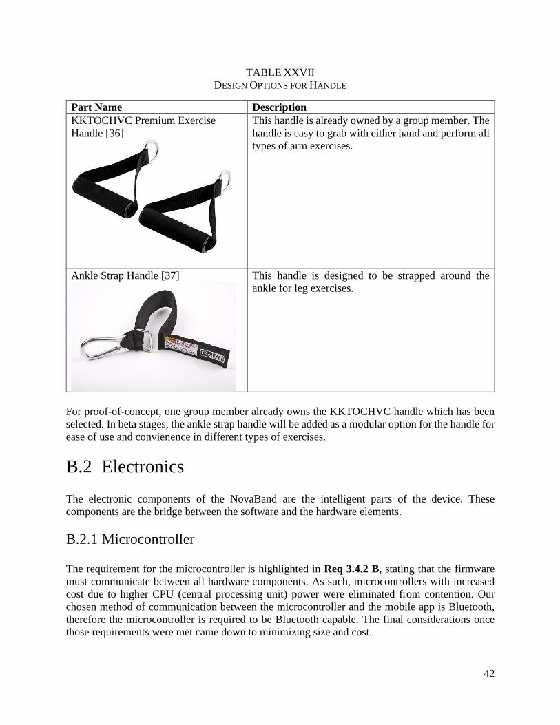
42
TABLE XXVII
DESIGN OPTIONS FOR HANDLE
Part Name Description
KKTOCHVC Premium Exercise
Handle [36]
This handle is already owned by a group member. The
handle is easy to grab with either hand and perform all
types of arm exercises.
Ankle Strap Handle [37]
This handle is designed to be strapped around the
ankle for leg exercises.
For proof-of-concept, one group member already owns the KKTOCHVC handle which has been
selected. In beta stages, the ankle strap handle will be added as a modular option for the handle for
ease of use and convienence in different types of exercises.
B.2 Electronics
The electronic components of the NovaBand are the intelligent parts of the device. These
components are the bridge between the software and the hardware elements.
B.2.1 Microcontroller
The requirement for the microcontroller is highlighted in Req 3.4.2 B, stating that the firmware
must communicate between all hardware components. As such, microcontrollers with increased
cost due to higher CPU (central processing unit) power were eliminated from contention. Our
chosen method of communication between the microcontroller and the mobile app is Bluetooth,
therefore the microcontroller is required to be Bluetooth capable. The final considerations once
those requirements were met came down to minimizing size and cost.

43
B.2.1.1 Microcontroller Options
TABLE XXVIII outlines the different options for microcontrollers that were considered in the
research process for the NovaBand proof-of-concept. Both Arduino and Raspberry Pi families
outside of the Nano and Zero respectively were considered as well, however, they were quickly
eliminated due to size constraints and the lack of a need for a high-powered CPU.
TABLE XXVIII
DESIGN OPTIONS FOR MICROCONTROLLER
Design Option Technical Specifications
Arduino Nano [11]
Operating Voltage 5V
Clock Speed 16MHz
DC Current per I/O Pins 40mA
Input Voltage 7-12V
Power Consumption 19mA
PCB Size 18mm x 45mm
Weight 7g
Raspberry Pi Zero [38]
Operating Voltage 5V
Clock Speed 1GHz
DC Current per I/O Pins 40mA
Input Voltage 5.1V
Power Consumption 100mA (typical)
PCB Size 30mm x 65mm
Weight 9g
Printed Circuit Board (PCB)
All technical specifications vary depending on
the board that is designed.
The Arduino Nano is a simple microcontroller designed for use in small projects with no need for
large amounts of processing power.
The Raspberry Pi Zero is an extremely low-cost board, with a relatively high-powered CPU for
the size of the board. The Pi Zero is a standalone computer and functions as such, but also has
general-purpose input/output, or GPIO, pins to allow for connections to multiple external devices
which allows it to function as a microcontroller as well as a computer.
Finally, the last option considered was to use a custom printed circuit board. A printed circuit
board, or PCB, has specific components soldered onto the board at the request of the purchaser.
PCBs are very versatile and relatively inexpensive. However, to properly make use of the benefits
of a PCB, one would need to know all the exact requirements in advance of fabricating and
ordering the board.
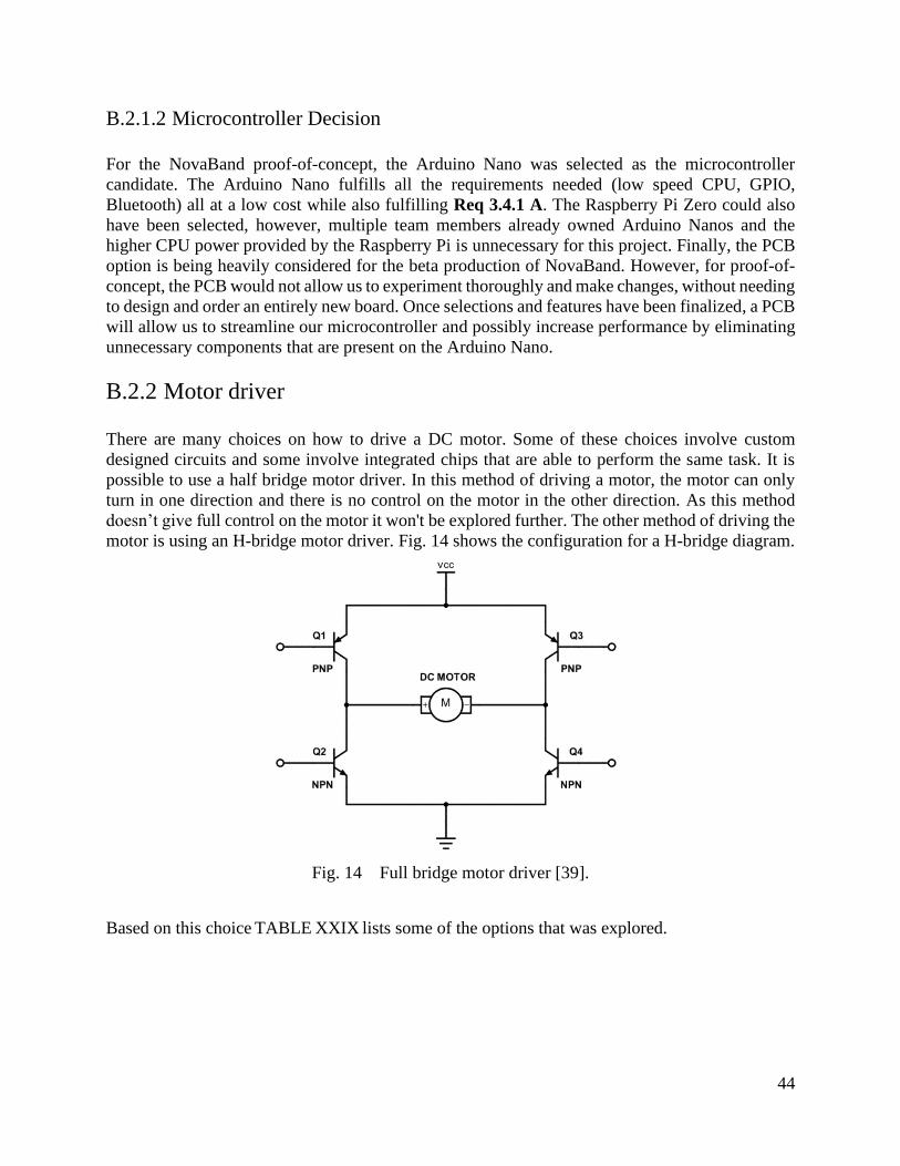
44
B.2.1.2 Microcontroller Decision
For the NovaBand proof-of-concept, the Arduino Nano was selected as the microcontroller
candidate. The Arduino Nano fulfills all the requirements needed (low speed CPU, GPIO,
Bluetooth) all at a low cost while also fulfilling Req 3.4.1 A. The Raspberry Pi Zero could also
have been selected, however, multiple team members already owned Arduino Nanos and the
higher CPU power provided by the Raspberry Pi is unnecessary for this project. Finally, the PCB
option is being heavily considered for the beta production of NovaBand. However, for proof-of-
concept, the PCB would not allow us to experiment thoroughly and make changes, without needing
to design and order an entirely new board. Once selections and features have been finalized, a PCB
will allow us to streamline our microcontroller and possibly increase performance by eliminating
unnecessary components that are present on the Arduino Nano.
B.2.2 Motor driver
There are many choices on how to drive a DC motor. Some of these choices involve custom
designed circuits and some involve integrated chips that are able to perform the same task. It is
possible to use a half bridge motor driver. In this method of driving a motor, the motor can only
turn in one direction and there is no control on the motor in the other direction. As this method
doesn’t give full control on the motor it won't be explored further. The other method of driving the
motor is using an H-bridge motor driver. Fig. 14 shows the configuration for a H-bridge diagram.
Fig. 14 Full bridge motor driver [39].
Based on this choice TABLE XXIX lists some of the options that was explored.
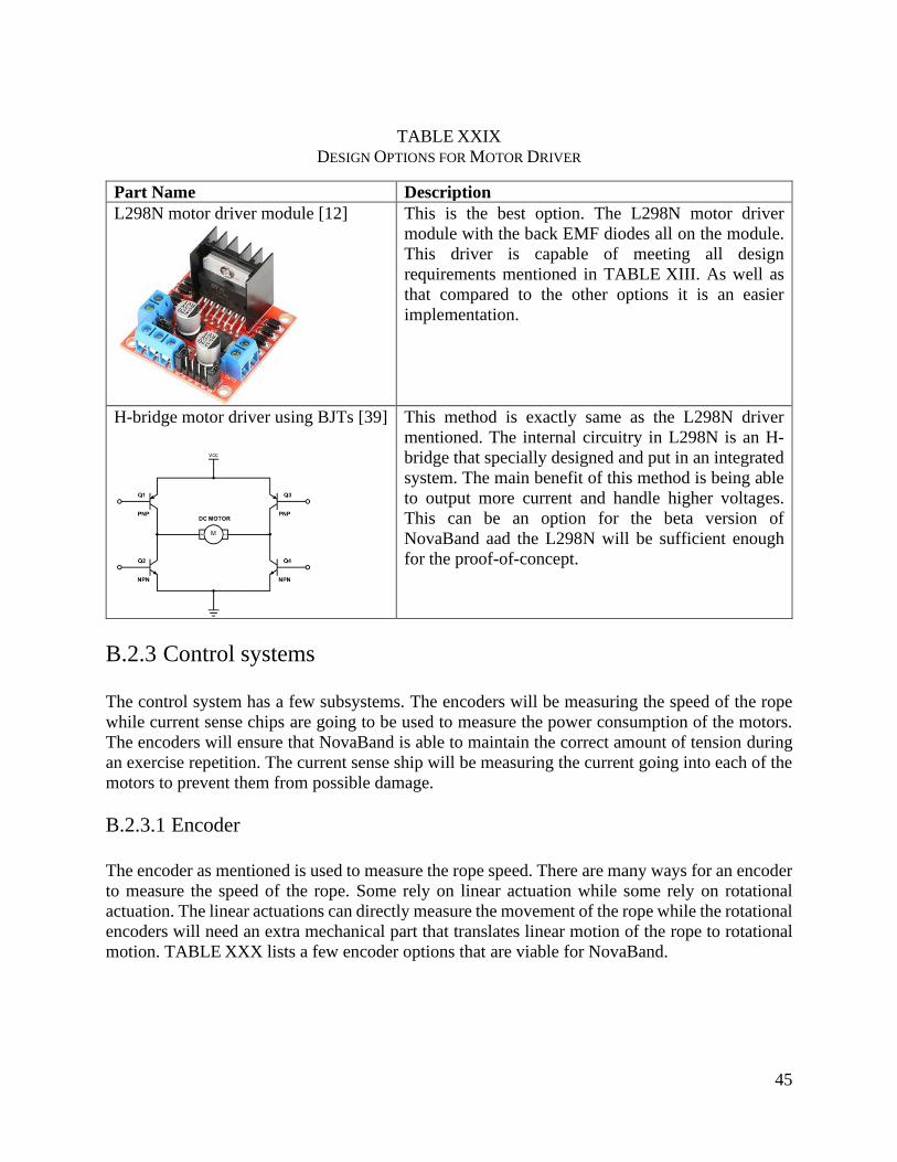
45
TABLE XXIX
DESIGN OPTIONS FOR MOTOR DRIVER
Part Name Description
L298N motor driver module [12]
This is the best option. The L298N motor driver
module with the back EMF diodes all on the module.
This driver is capable of meeting all design
requirements mentioned in TABLE XIII. As well as
that compared to the other options it is an easier
implementation.
H-bridge motor driver using BJTs [39]
This method is exactly same as the L298N driver
mentioned. The internal circuitry in L298N is an H-
bridge that specially designed and put in an integrated
system. The main benefit of this method is being able
to output more current and handle higher voltages.
This can be an option for the beta version of
NovaBand aad the L298N will be sufficient enough
for the proof-of-concept.
B.2.3 Control systems
The control system has a few subsystems. The encoders will be measuring the speed of the rope
while current sense chips are going to be used to measure the power consumption of the motors.
The encoders will ensure that NovaBand is able to maintain the correct amount of tension during
an exercise repetition. The current sense ship will be measuring the current going into each of the
motors to prevent them from possible damage.
B.2.3.1 Encoder
The encoder as mentioned is used to measure the rope speed. There are many ways for an encoder
to measure the speed of the rope. Some rely on linear actuation while some rely on rotational
actuation. The linear actuations can directly measure the movement of the rope while the rotational
encoders will need an extra mechanical part that translates linear motion of the rope to rotational
motion. TABLE XXX lists a few encoder options that are viable for NovaBand.
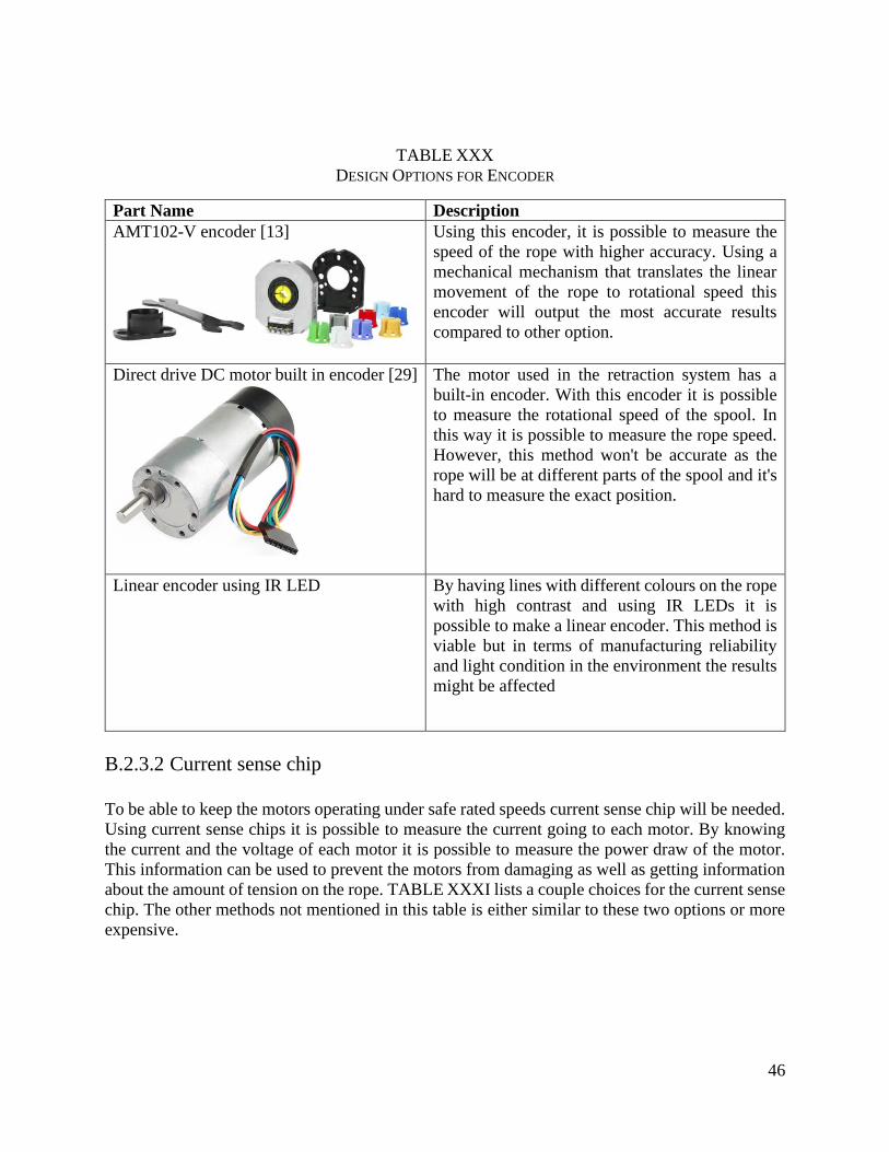
46
TABLE XXX
DESIGN OPTIONS FOR ENCODER
Part Name Description
AMT102-V encoder [13]
Using this encoder, it is possible to measure the
speed of the rope with higher accuracy. Using a
mechanical mechanism that translates the linear
movement of the rope to rotational speed this
encoder will output the most accurate results
compared to other option.
Direct drive DC motor built in encoder [29]
The motor used in the retraction system has a
built-in encoder. With this encoder it is possible
to measure the rotational speed of the spool. In
this way it is possible to measure the rope speed.
However, this method won't be accurate as the
rope will be at different parts of the spool and it's
hard to measure the exact position.
Linear encoder using IR LED By having lines with different colours on the rope
with high contrast and using IR LEDs it is
possible to make a linear encoder. This method is
viable but in terms of manufacturing reliability
and light condition in the environment the results
might be affected
B.2.3.2 Current sense chip
To be able to keep the motors operating under safe rated speeds current sense chip will be needed.
Using current sense chips it is possible to measure the current going to each motor. By knowing
the current and the voltage of each motor it is possible to measure the power draw of the motor.
This information can be used to prevent the motors from damaging as well as getting information
about the amount of tension on the rope. TABLE XXXI lists a couple choices for the current sense
chip. The other methods not mentioned in this table is either similar to these two options or more
expensive.

47
TABLE XXXI
DESIGN OPTIONS FOR CURRENT SENSE CHIP
Part Name Description
MLX91220 current sensor [14]
Using an integrated chip like MLX91220 and a
low resistance high accuracy resistor outputs the
most accurate results as the current will be
measured directly from the wires that are attached
to each motor. This option is also cheaper than the
other methods mentioned below
CR9321 current sensor [40]
The other method is using current sensors that
enclose the wiring that goes to each motor and
measures the current using the magnetic field
generated by the current. This method is much
more expensive while less accurate and only good
for really high current systems which is not
needed for NovaBand.
B.2.4 Power source
There are multiple ways to power the device. As mentioned in the body a power supply will be
used for the proof of concept while lithium-ion batteries are the chosen option. Pros and cons of
each method is shown in TABLE XXXII. TABLE XXXII
DESIGN OPTIONS FOR
TABLE XXXII
DESIGN OPTIONS FOR POWER SOURCE
Part Name Description
Lab power supply This method is reliable and provides enough
power for NovaBand to operate. The power
supply provided from the engineering lab is able
to provide up to 30V and 3 amps which is higher
than the needs for the device.
Lithiom-ion battery cells For beta, the source of power will be changed to
batteries. Using batteries NovaBand can operate
without being attached to power supply. This
method is not used for the proof-of-concept as
focusing on the other parts of the product was
more important and operating lithion-ion
batteries comes with its own risks which will
require proper battery management circuit.
48
Directly powered from the wall using
internal power supply
This method is not ideal as NovaBand has to be
pluggd into the wall at all times to operate while
being more danagarous. In addition, heavy AC
and DC converters will need to be added.
B.3 Software
The software component of the product operates in a domain adjacent to the physical device.
Broadly, the software works in tandem with the electrical and mechanical subsystems to configure
the device state dynamically depending on the needs of a particular rehabilitation exercise.
B.3.1 Physiotherapist-to-Device Interface
The physiotherapist-to-device interface is a critical bridge between the product’s software and
hardware components. The physiotherapist must be able to easily and precisely control the device
to provide the best rehabilitation work out for their patients.
B.3.1.1 Physiotherapist-to-Device Interface Options
For the physiotherapist-to-device interface, three options were considered: a mobile application,
an on-device button interface, and a custom remote control. Each option needs to meet both Req
3.1.1 A and Req 3.4.1 A, which require that the device must be able to programmatically vary
resistance and must respond to user input within one second, respectively.
A mobile application is a low-cost, highly customizable design option. The graphical user interface
of an app, if well designed, creates an easy-to-use abstraction for controlling the device. If changes
to the app are needed, they can be made available via software updates and quickly applied. Since
an app functions on mobile phone software, the phone’s hardware peripherals, including the
communication components, can be utilized. However, some challenges arise due to differences
in operating system specific features between Android and iOS. Additionally, data transmission
latency and operating range depends on the data transmission protocol used, such as WiFi and
Bluetooth.
Alternatively, an on-device button interface allows the NovaBand device to be completely stand-
alone while still providing a way for physiotherapists to interact with the device. This approach
comes with a couple of issues, however: lack of post-manufacturing customization, device
fragility, additional production cost, and a potentially difficult learning curve for users. Button
mappings that cover all possible configurations would be far too complex to operate or require
additional clarifcation. Unfortunately, this approach also adds another point of failure to the overall
design of the device; if the buttons stops working, the physiotherapist has no way to confgure the
device.
The final option considered was a custom remote control. This option has many similarities to the
on-device button interface in that it still suffers from a lack of post-manufacturing customization.
Additionally, the complexity of the customization options would force the design to include many
49
buttons which is both clumsy and unintuitive. It is also worth noting that the remote itself is
susceptible to damage from being dropped and will be harder to replace than a mobile phone.
Lastly, the remote also requires wireless data transmission, just as the mobile application does.
B.3.1.2 Physiotherapist-to-Device Decision
The device must be able to programmatically vary resistance according to Req 3.1.1 A. The option
that best fulfills this requirement while leading to the fewest additional challenges is the mobile
app. Both the built-in button interface and remote control options cost more than the app, will be
more difficult to use, and cannot be easily changed after they are. In contrast, the app is free to
develop, offers a familiar interface to users, and, most importantly, can be changed via software
updates after the initial version is deployed.
Req 3.4.1 A notes that the device must respond to user input changes within one second. All design
options considered are likely to impose a similar latency, but the app can choose from Bluetooth,
Wi-Fi, and other protocols to communicate. Compared to the app, the other design options do not
offer sufficient communication protocol alternatives which can guarantee meeting the latency
requirements.
To summarize, Req 3.1.1 A and Req 3.4.1 A require the device to both have the ability to
programmatically vary resistance and respond to input within one second. Three design options
were considered: a mobile application, an on-device button interface, and a remote control. Among
these options, a mobile application has been selected due to its low cost, ease of updating, and
support for multiple data transmission protocols.
B.3.2 Data Transmission
As stated previously, the app will need a wireless protocol to communicate with the device. Req
3.4.1 A requires one second for data transmission and settings updates. As such, the data
transmission needs to be performed in under one second and the protocol selected must meet that
requirement.
B.3.2.1 Data Transmission Options
TABLE XXXIII outlines the different options for data transmission. There are multiple options
that exist to wirelessly transmit data: Bluetooth, Wi-Fi, and Zigbee.
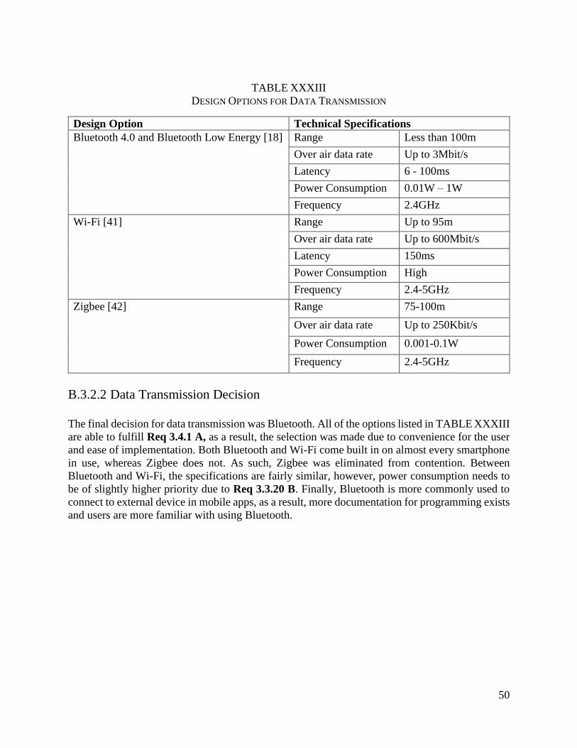
50
TABLE XXXIII
DESIGN OPTIONS FOR DATA TRANSMISSION
Design Option Technical Specifications
Bluetooth 4.0 and Bluetooth Low Energy [18]
Range Less than 100m
Over air data rate Up to 3Mbit/s
Latency 6 - 100ms
Power Consumption 0.01W – 1W
Frequency 2.4GHz
Wi-Fi [41]
Range Up to 95m
Over air data rate Up to 600Mbit/s
Latency 150ms
Power Consumption High
Frequency 2.4-5GHz
Zigbee [42]
Range 75-100m
Over air data rate Up to 250Kbit/s
Power Consumption 0.001-0.1W
Frequency 2.4-5GHz
B.3.2.2 Data Transmission Decision
The final decision for data transmission was Bluetooth. All of the options listed in TABLE XXXIII
are able to fulfill Req 3.4.1 A, as a result, the selection was made due to convenience for the user
and ease of implementation. Both Bluetooth and Wi-Fi come built in on almost every smartphone
in use, whereas Zigbee does not. As such, Zigbee was eliminated from contention. Between
Bluetooth and Wi-Fi, the specifications are fairly similar, however, power consumption needs to
be of slightly higher priority due to Req 3.3.20 B. Finally, Bluetooth is more commonly used to
connect to external device in mobile apps, as a result, more documentation for programming exists
and users are more familiar with using Bluetooth.
Related Documents