COMPACT V/f & SENSORLESS INVERTER BDI50 English User manual Rev. 0.5 – 13-1-2017

Welcome message from author
This document is posted to help you gain knowledge. Please leave a comment to let me know what you think about it! Share it to your friends and learn new things together.
Transcript
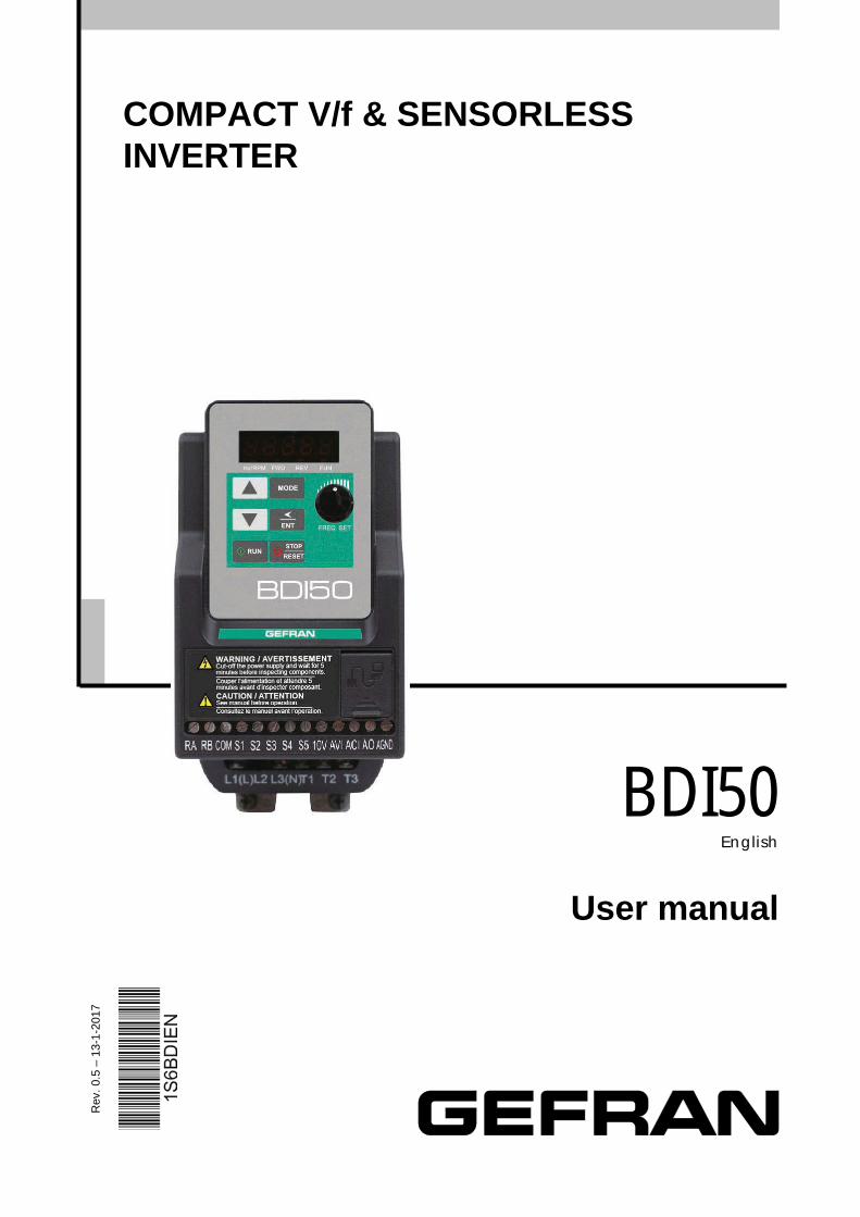
COMPACT V/f & SENSORLESS INVERTER
BDI50 English
User manual
Rev
. 0.5
– 1
3-1-
2017
------------------------------------------------------------------------------------------------------------------------------ Software version This manual is updated according the software version V 1.04 The identification number of the software version is indicated on the identification plate of the drive or can be checked with the par. 13.01. Thank you for choosing this Gefran product. We will be glad to receive any possible information which could help us improving this manual. The e-mail address is the following: techdoc@ gefran.com. Before using the product, read the safety instruction section carefully. Keep the manual in a safe place and available to engineering and installation personnel during the product functioning period. Gefran S.p.A has the right to modify products, data and dimensions without notice. The data can only be used for the product description and they can not be understood as legally stated properties. All rights reserved
I
Table of Contents Chapter 0 Preface 0-1
0.1 Preface 0-1 Chapter 1 Safety Precautions 1-1
1.1 Before Power UP 1-1 1.2 During Power UP 1-2 1.3 Before Operation 1-2 1.4 During Operation 1-3 1.5 Inverter Disposal 1-3 Chapter 2 Part Number Definition 2-1 2.1 Model part number 2-1 2.2 Standard Product Specification 2-2 Chapter 3 Environment & Installation 3-1
3.1 Environment 3-1 3.2 Installation 3-3 3.2.1 Installation methods 3-3 3.2.2 Installation space 3-6 3.2.3 Derating curves 3-9 3.2.4 Capacitor reforming Guide after long storage 3-10 3.3 Wiring guidelines 3-11 3.3.1 Main considerations 3-11 3.3.2 Power cables 3-13 3.3.3 Control cable selection and wiring 3-13 3.3.4 Wiring and EMC guidelines 3-14 3.3.5 Failure liability 3-15 3.3.6 Considerations for peripheral equipment 3-17 3.3.7 Ground connection 3-18 3.4 Specifications 3-19 3.4.1 Product Specifications 3-19 3.4.2 General Specifications 3-21 3.5 Standard wiring 3-23 3.5.1 200V Single phase (NPN input) 3-23 3.5.2 200V Single phase (PNP input) 3-24 3.5.3 230V Three phase (NPN input) 3-25 3.5.4 400V Three phase (PNP input) 3-26 3.5.5 400V Three phase (NPN input) 3-27 3.6 Terminal Description 3-29 3.6.1 Description of main circuit terminals 3-29 3.6.2 Control circuit terminal description 3-30 3.7 Dimensions and weight 3-32
3.8 EMC filter Disconnection 3-37 Chapter 4 Software Index 4-1
4.1 Keypad Description 4-1 4.1.1 Operator Panel Functions 4-1
II
4.1.2 Digital Display Description 4-2 4.1.3 Digital Display Setup 4-4 4.1.4 Example of Keypad Operation 4-6 4.1.5 Operation Control 4-8 4.2 Programmable Parameter Groups 4-9 4.3 Parameter Function Description 4-24
Chapter 5 Troubleshooting and Maintenance 5-1 5.1 Error Display and Corrective Action 5-1 5.1.1 Manual Reset and Auto-Reset 5-1 5.1.2 Keypad Operation Error Instruction 5-3 5.1.3 Special conditions 5-4 5.2 General troubleshooting 5-5 5.3 Routine and periodic inspection 5-6 5.4 Maintenance 5-7
Chapter 6 Accessories 6-1 6.1 Input choke Specifications 6-1 6.2 Output choke Specifications 6-1 6.3 Fuse Specification 6-1 6.4 Fuse Specification (UL Model Recommended) 6-2 6.5 Braking Resistor 6-3 6.6 Copy Unit (KB-BDI/VDI) 6-4 6.7 Communication options 6-4 6.8 RJ45 to USB connecting Cable (1.8m) 6-5
Appendix 1 BDI50 Parameters Setting List App1-1 Appendix 2 Instructions for UL App2-1 Appendix 3 BDI50 Communication protocols App3-1 Modbus communication protocol App3-1 BACnet communication protocol App3-18 Appendix 4 Cable RJ45 to USB instruction manual App4-1 Appendix 5 BDI50 series accessories manual App5-1
0-1
Chapter 0 Preface 0.1 Preface
To extend the performance of the product and ensure personnel safety, please read this manual thoroughly before using the inverter. Should there be any problem in using the product that cannot be solved with the information provided in the manual, contact our technical or sales representative who will be willing to help you.
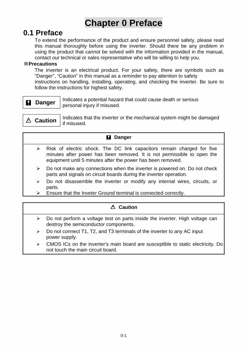
※Precautions The inverter is an electrical product. For your safety, there are symbols such as “Danger”, “Caution” in this manual as a reminder to pay attention to safety instructions on handling, installing, operating, and checking the inverter. Be sure to follow the instructions for highest safety.
Danger Indicates a potential hazard that could cause death or serious personal injury if misused.
Caution Indicates that the inverter or the mechanical system might be damaged if misused.
Danger
Risk of electric shock. The DC link capacitors remain charged for five minutes after power has been removed. It is not permissible to open the equipment until 5 minutes after the power has been removed.
Do not make any connections when the inverter is powered on. Do not check parts and signals on circuit boards during the inverter operation.
Do not disassemble the inverter or modify any internal wires, circuits, or parts.
Ensure that the Inveter Ground terminal is connected correctly.
Caution
Do not perform a voltage test on parts inside the inverter. High voltage can destroy the semiconductor components.
Do not connect T1, T2, and T3 terminals of the inverter to any AC input power supply.
CMOS ICs on the inverter’s main board are susceptible to static electricity. Do not touch the main circuit board.
1-1
Chapter 1 Safety Precautions 1.1 Before Power Up
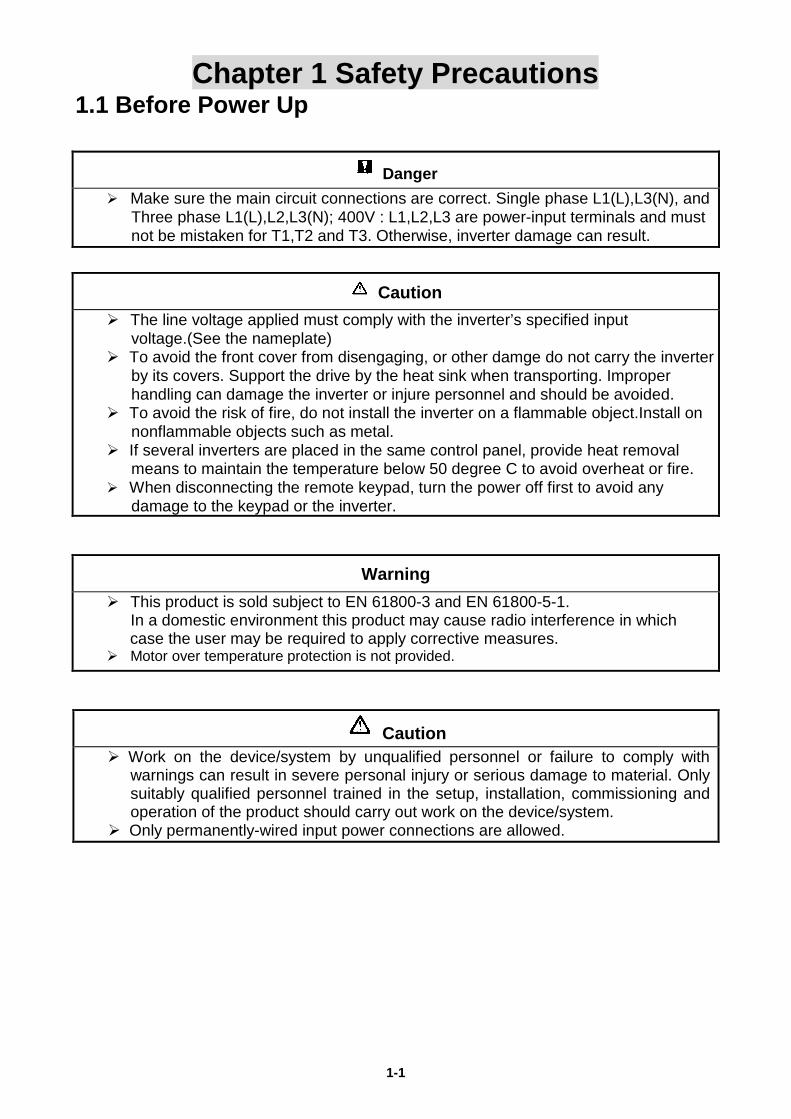
Danger Make sure the main circuit connections are correct. Single phase L1(L),L3(N), and
Three phase L1(L),L2,L3(N); 400V : L1,L2,L3 are power-input terminals and must not be mistaken for T1,T2 and T3. Otherwise, inverter damage can result.
Caution The line voltage applied must comply with the inverter’s specified input
voltage.(See the nameplate) To avoid the front cover from disengaging, or other damge do not carry the inverter
by its covers. Support the drive by the heat sink when transporting. Improper handling can damage the inverter or injure personnel and should be avoided.
To avoid the risk of fire, do not install the inverter on a flammable object.Install on nonflammable objects such as metal.
If several inverters are placed in the same control panel, provide heat removal means to maintain the temperature below 50 degree C to avoid overheat or fire.
When disconnecting the remote keypad, turn the power off first to avoid any damage to the keypad or the inverter.
Warning
This product is sold subject to EN 61800-3 and EN 61800-5-1. In a domestic environment this product may cause radio interference in which
case the user may be required to apply corrective measures. Motor over temperature protection is not provided.
Caution Work on the device/system by unqualified personnel or failure to comply with
warnings can result in severe personal injury or serious damage to material. Only suitably qualified personnel trained in the setup, installation, commissioning and operation of the product should carry out work on the device/system.
Only permanently-wired input power connections are allowed.
1-2
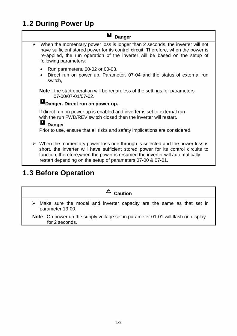
1.2 During Power Up Danger
When the momentary power loss is longer than 2 seconds, the inverter will not have sufficient stored power for its control circuit. Therefore, when the power is re-applied, the run operation of the inverter will be based on the setup of following parameters:
• Run parameters. 00-02 or 00-03. • Direct run on power up. Parameter. 07-04 and the status of external run
switch,
Note-: the start operation will be regardless of the settings for parameters 07-00/07-01/07-02.
Danger. Direct run on power up. If direct run on power up is enabled and inverter is set to external run with the run FWD/REV switch closed then the inverter will restart.
Danger Prior to use, ensure that all risks and safety implications are considered.
When the momentary power loss ride through is selected and the power loss is
short, the inverter will have sufficient stored power for its control circuits to function, therefore,when the power is resumed the inverter will automatically restart depending on the setup of parameters 07-00 & 07-01.
1.3 Before Operation
Caution
Make sure the model and inverter capacity are the same as that set in parameter 13-00.
Note : On power up the supply voltage set in parameter 01-01 will flash on display for 2 seconds.
1-3
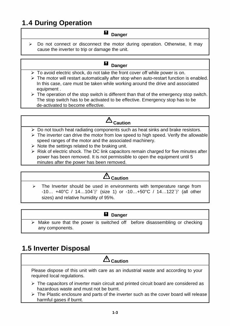
1.4 During Operation Danger
Do not connect or disconnect the motor during operation. Otherwise, It may cause the inverter to trip or damage the unit.
Caution Do not touch heat radiating components such as heat sinks and brake resistors. The inverter can drive the motor from low speed to high speed. Verify the allowable
speed ranges of the motor and the associated machinery. Note the settings related to the braking unit. Risk of electric shock. The DC link capacitors remain charged for five minutes after
power has been removed. It is not permissible to open the equipment until 5 minutes after the power has been removed.
Caution The Inverter should be used in environments with temperature range from
-10… +40°C / 14…104℉ (size 1) or -10…+50°C / 14…122℉ (all other sizes) and relative humidity of 95%.
Danger Make sure that the power is switched off before disassembling or checking
any components.
1.5 Inverter Disposal Caution
Please dispose of this unit with care as an industrial waste and according to your required local regulations. The capacitors of inverter main circuit and printed circuit board are considered as
hazardous waste and must not be burnt. The Plastic enclosure and parts of the inverter such as the cover board will release
harmful gases if burnt.
Danger To avoid electric shock, do not take the front cover off while power is on. The motor will restart automatically after stop when auto-restart function is enabled.
In this case, care must be taken while working around the drive and associated equipment .
The operation of the stop switch is different than that of the emergency stop switch. The stop switch has to be activated to be effective. Emergency stop has to be de-activated to become effective.
2-1
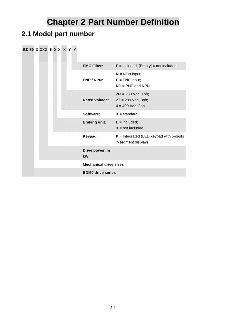
Chapter 2 Part Number Definition 2.1 Model part number BDI50 -X XXX -K X X -X -Y -Y
EMC Filter: F = included; [Empty] = not included
PNP / NPN: N = NPN input; P = PNP input; NP = PNP and NPN
Rated voltage: 2M = 230 Vac, 1ph; 2T = 230 Vac, 3ph; 4 = 400 Vac, 3ph
Software: X = standard
Braking unit:
B = included; X = not included
Keypad:
K = Integrated (LED keypad with 5-digits 7-segment display)
Drive power, in kW
Mechanical drive sizes
BDI50 drive series
2-2
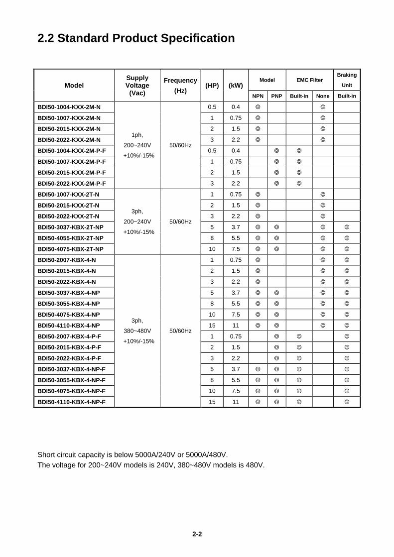
2.2 Standard Product Specification
Model Supply Voltage
(Vac)
Frequency (Hz)
(HP) (kW) Model EMC Filter
Braking
Unit
NPN PNP Built-in None Built-in
BDI50-1004-KXX-2M-N
1ph,
200~240V
+10%/-15%
50/60Hz
0.5 0.4 ◎ ◎
BDI50-1007-KXX-2M-N 1 0.75 ◎ ◎
BDI50-2015-KXX-2M-N 2 1.5 ◎ ◎
BDI50-2022-KXX-2M-N 3 2.2 ◎ ◎
BDI50-1004-KXX-2M-P-F 0.5 0.4 ◎ ◎
BDI50-1007-KXX-2M-P-F 1 0.75 ◎ ◎
BDI50-2015-KXX-2M-P-F 2 1.5 ◎ ◎
BDI50-2022-KXX-2M-P-F 3 2.2 ◎ ◎
BDI50-1007-KXX-2T-N
3ph,
200~240V
+10%/-15%
50/60Hz
1 0.75 ◎ ◎
BDI50-2015-KXX-2T-N 2 1.5 ◎ ◎
BDI50-2022-KXX-2T-N 3 2.2 ◎ ◎
BDI50-3037-KBX-2T-NP 5 3.7 ◎ ◎ ◎ ◎
BDI50-4055-KBX-2T-NP 8 5.5 ◎ ◎ ◎ ◎
BDI50-4075-KBX-2T-NP 10 7.5 ◎ ◎ ◎ ◎
BDI50-2007-KBX-4-N
3ph,
380~480V
+10%/-15%
50/60Hz
1 0.75 ◎ ◎ ◎
BDI50-2015-KBX-4-N 2 1.5 ◎ ◎ ◎
BDI50-2022-KBX-4-N 3 2.2 ◎ ◎ ◎
BDI50-3037-KBX-4-NP 5 3.7 ◎ ◎ ◎ ◎
BDI50-3055-KBX-4-NP 8 5.5 ◎ ◎ ◎ ◎
BDI50-4075-KBX-4-NP 10 7.5 ◎ ◎ ◎ ◎
BDI50-4110-KBX-4-NP 15 11 ◎ ◎ ◎ ◎
BDI50-2007-KBX-4-P-F 1 0.75 ◎ ◎ ◎
BDI50-2015-KBX-4-P-F 2 1.5 ◎ ◎ ◎
BDI50-2022-KBX-4-P-F 3 2.2 ◎ ◎ ◎
BDI50-3037-KBX-4-NP-F 5 3.7 ◎ ◎ ◎ ◎
BDI50-3055-KBX-4-NP-F 8 5.5 ◎ ◎ ◎ ◎
BDI50-4075-KBX-4-NP-F 10 7.5 ◎ ◎ ◎ ◎
BDI50-4110-KBX-4-NP-F 15 11 ◎ ◎ ◎ ◎
Short circuit capacity is below 5000A/240V or 5000A/480V. The voltage for 200~240V models is 240V, 380~480V models is 480V.
3-1
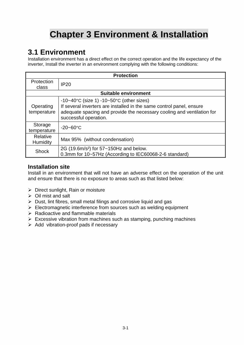
Chapter 3 Environment & Installation 3.1 Environment Installation environment has a direct effect on the correct operation and the life expectancy of the inverter, Install the inverter in an environment complying with the following conditions:
Protection Protection
class IP20
Suitable environment
Operating temperature
-10~40°C (size 1) -10~50°C (other sizes) If several inverters are installed in the same control panel, ensure adequate spacing and provide the necessary cooling and ventilation for successful operation.
Storage temperature -20~60°C
Relative Humidity Max 95% (without condensation)
Shock 2G (19.6m/s²) for 57~150Hz and below. 0.3mm for 10~57Hz (According to IEC60068-2-6 standard)
Installation site Install in an environment that will not have an adverse effect on the operation of the unit and ensure that there is no exposure to areas such as that listed below: Direct sunlight, Rain or moisture Oil mist and salt Dust, lint fibres, small metal filings and corrosive liquid and gas Electromagnetic interference from sources such as welding equipment Radioactive and flammable materials Excessive vibration from machines such as stamping, punching machines Add vibration-proof pads if necessary
3-2
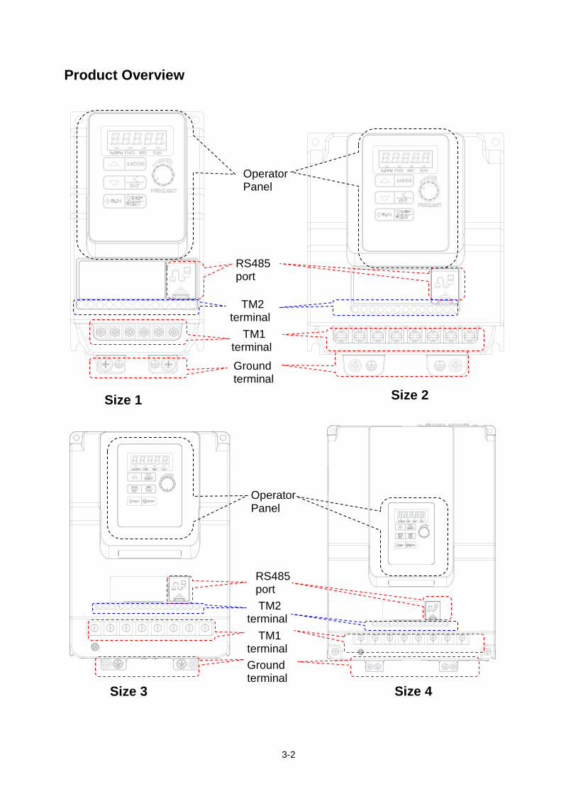
Product Overview
Size 3
Size 4
RS485 port
Operator Panel
TM2 terminal TM1 terminal
Ground terminal
Operator Panel
RS485 port TM2
terminal
TM1 terminal Ground terminal
Size 1
Size 2
3-3
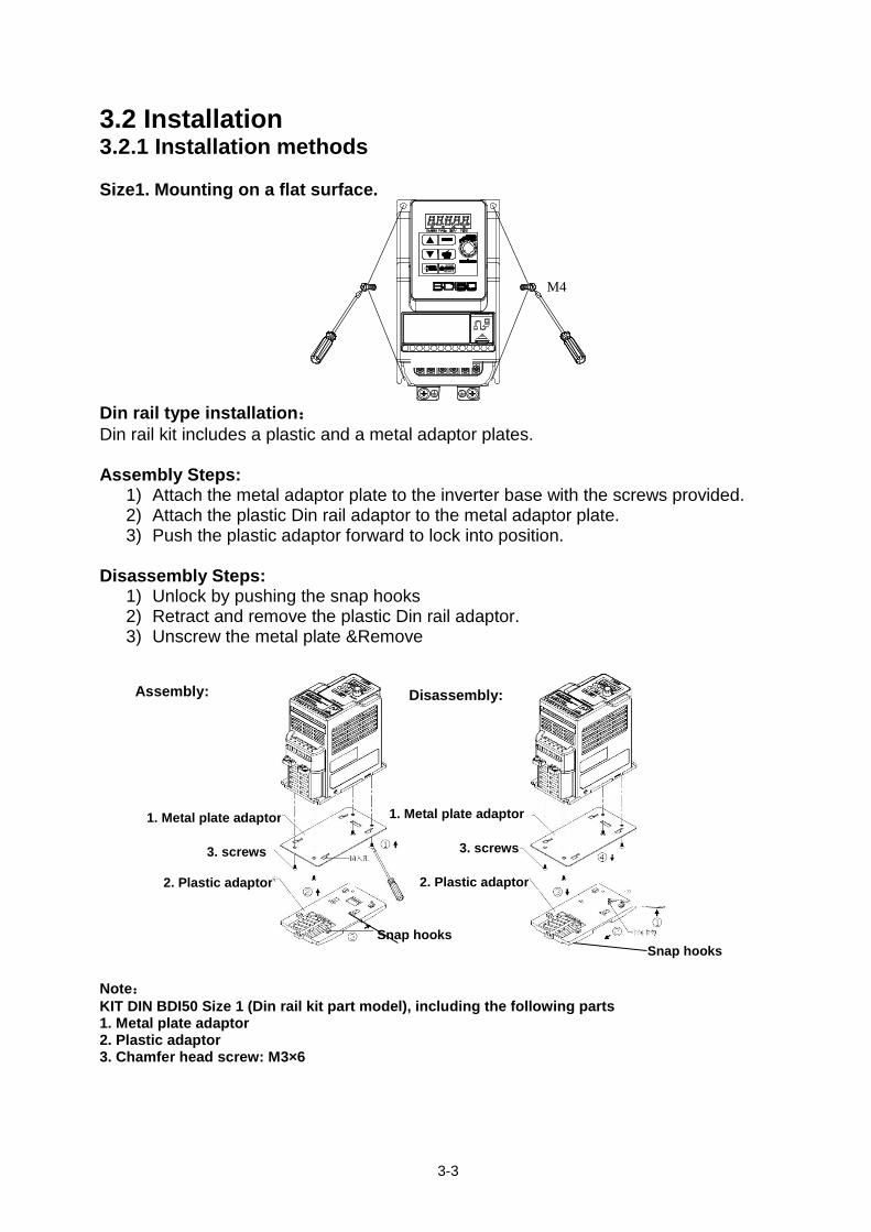
3.2 Installation 3.2.1 Installation methods Size1. Mounting on a flat surface.
Din rail type installation: Din rail kit includes a plastic and a metal adaptor plates. Assembly Steps:
1) Attach the metal adaptor plate to the inverter base with the screws provided. 2) Attach the plastic Din rail adaptor to the metal adaptor plate. 3) Push the plastic adaptor forward to lock into position.
Disassembly Steps:
1) Unlock by pushing the snap hooks 2) Retract and remove the plastic Din rail adaptor. 3) Unscrew the metal plate &Remove
Note: KIT DIN BDI50 Size 1 (Din rail kit part model), including the following parts 1. Metal plate adaptor 2. Plastic adaptor 3. Chamfer head screw: M3×6
M4
1. Metal plate adaptor
2. Plastic adaptor
Snap hooks
1. Metal plate adaptor
2. Plastic adaptor
Snap hooks
3. screws 3. screws
Assembly: Disassembly:
3-4
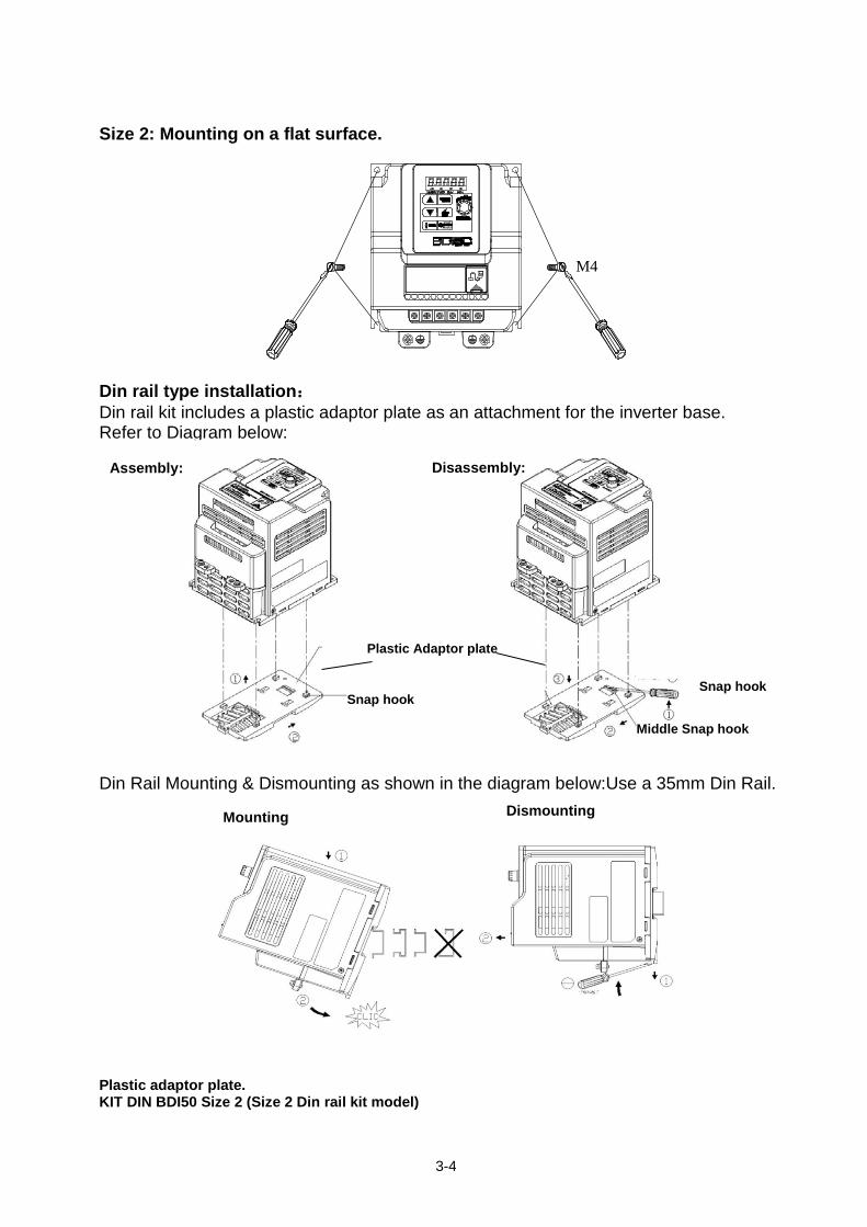
Size 2: Mounting on a flat surface.
Din rail type installation: Din rail kit includes a plastic adaptor plate as an attachment for the inverter base. Refer to Diagram below:
Din Rail Mounting & Dismounting as shown in the diagram below:Use a 35mm Din Rail.
Plastic adaptor plate. KIT DIN BDI50 Size 2 (Size 2 Din rail kit model)
M4
Mounting
Dismounting
Assembly:
Disassembly:
Plastic Adaptor plate
Snap hook
Middle Snap hook
Snap hook
3-5
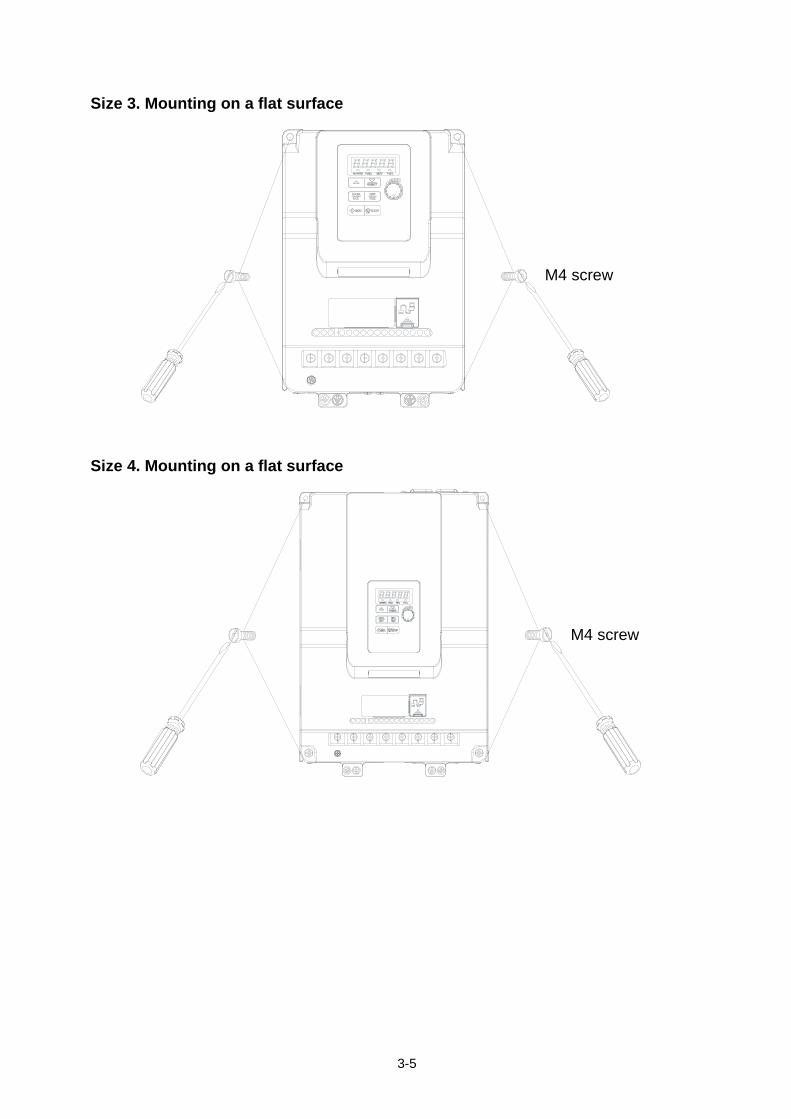
Size 3. Mounting on a flat surface
M4 螺丝
Size 4. Mounting on a flat surface
M4 螺丝
M4 screw
M4 screw
3-6
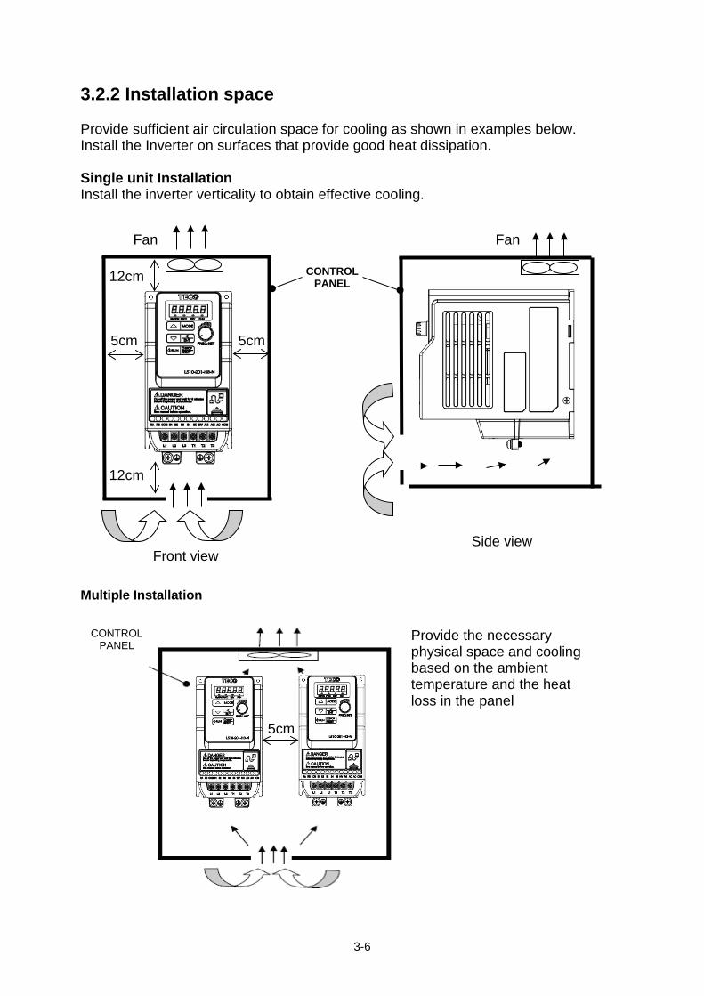
3.2.2 Installation space Provide sufficient air circulation space for cooling as shown in examples below. Install the Inverter on surfaces that provide good heat dissipation. Single unit Installation Install the inverter verticality to obtain effective cooling. Multiple Installation
5cm 5cm
12cm
12cm
Front view
CONTROL PANEL
Fan Fan
Side view
Provide the necessary physical space and cooling based on the ambient temperature and the heat loss in the panel
CONTROL PANEL
5cm
3-7
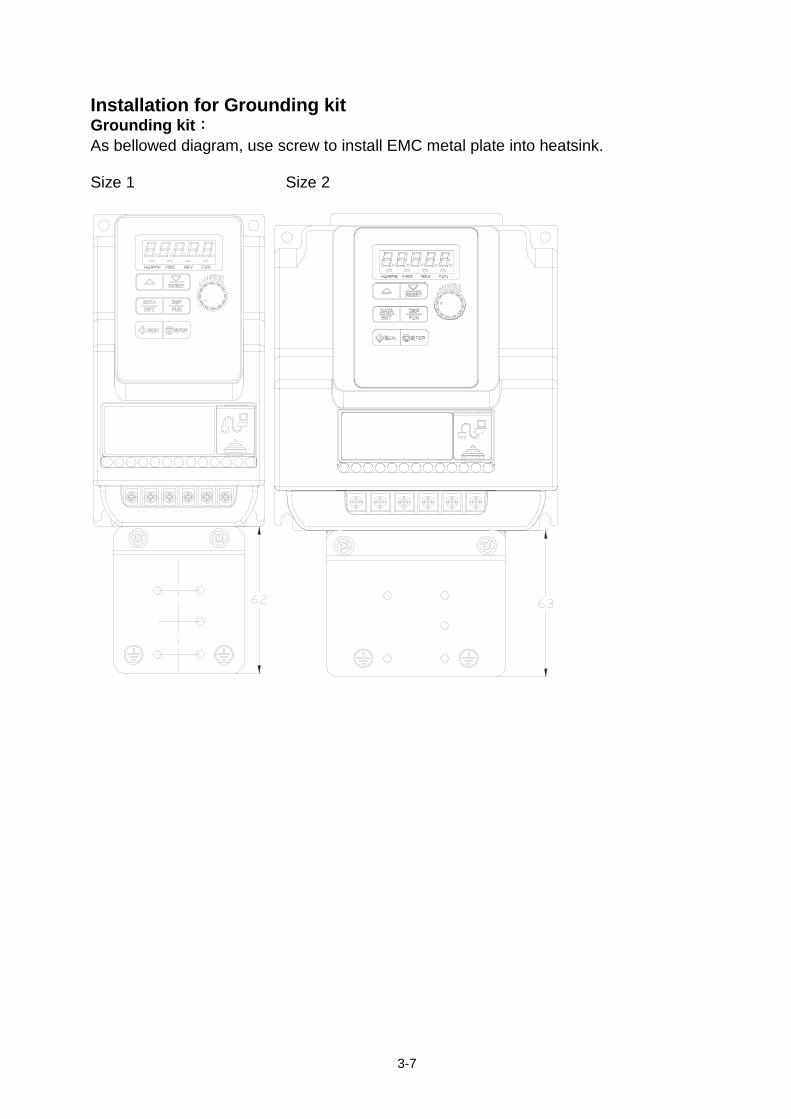
Installation for Grounding kit Grounding kit: As bellowed diagram, use screw to install EMC metal plate into heatsink. Size 1 Size 2
3-8
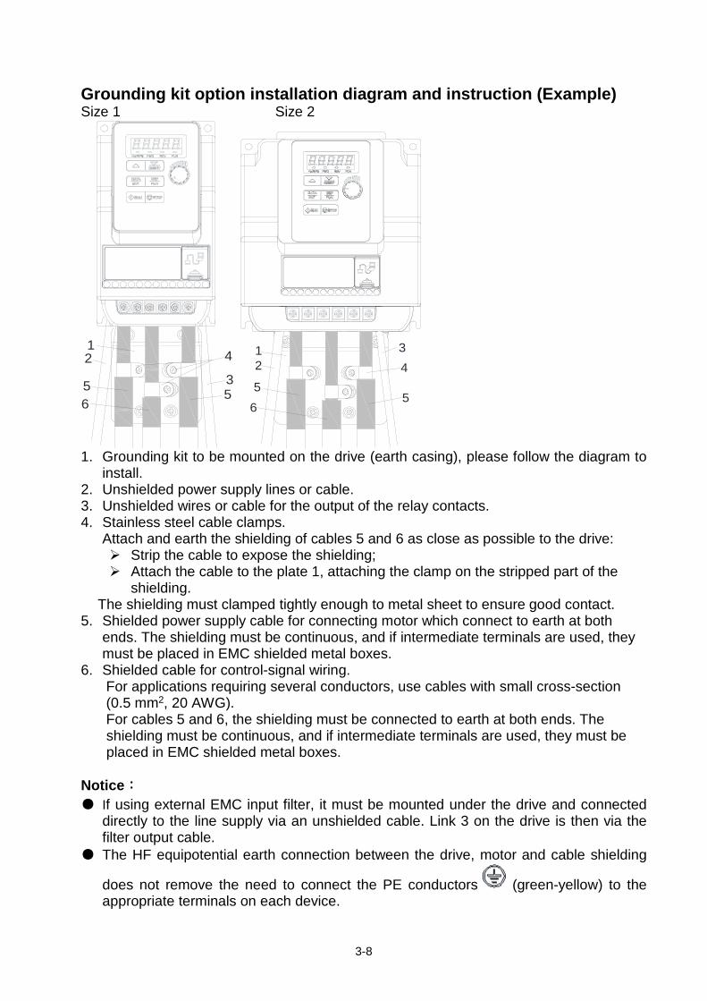
Grounding kit option installation diagram and instruction (Example) Size 1 Size 2
12
6
4
355
12
6
34
55
1. Grounding kit to be mounted on the drive (earth casing), please follow the diagram to
install. 2. Unshielded power supply lines or cable. 3. Unshielded wires or cable for the output of the relay contacts. 4. Stainless steel cable clamps.
Attach and earth the shielding of cables 5 and 6 as close as possible to the drive: Strip the cable to expose the shielding; Attach the cable to the plate 1, attaching the clamp on the stripped part of the
shielding. The shielding must clamped tightly enough to metal sheet to ensure good contact.
5. Shielded power supply cable for connecting motor which connect to earth at both ends. The shielding must be continuous, and if intermediate terminals are used, they must be placed in EMC shielded metal boxes.
6. Shielded cable for control-signal wiring. For applications requiring several conductors, use cables with small cross-section (0.5 mm2, 20 AWG). For cables 5 and 6, the shielding must be connected to earth at both ends. The shielding must be continuous, and if intermediate terminals are used, they must be placed in EMC shielded metal boxes.
Notice: ● If using external EMC input filter, it must be mounted under the drive and connected
directly to the line supply via an unshielded cable. Link 3 on the drive is then via the filter output cable.
● The HF equipotential earth connection between the drive, motor and cable shielding
does not remove the need to connect the PE conductors (green-yellow) to the appropriate terminals on each device.
3-9
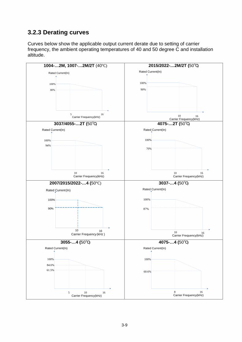
3.2.3 Derating curves Curves below show the applicable output current derate due to setting of carrier frequency, the ambient operating temperatures of 40 and 50 degree C and installation altitude.
1004-…2M, 1007-…2M/2T (40℃) 2015/2022-…2M/2T (50℃)
100%
80%
5 16
Rated Current(In)
Carrier Frequency(kHz)
100%
90%
10 16
Rated Current(In)
Carrier Frequency(kHz) 3037/4055-…2T (50℃) 4075-…2T (50℃)
100%
94%
10 16
Rated Current(In)
Carrier Frequency(kHz)
100%
70%
10 16
Rated Current(In)
Carrier Frequency(kHz) 2007/2015/2022-…4 (50℃) 3037-…4 (50℃)
100%
87%
10 16
Rated Current(In)
Carrier Frequency(kHz)
3055-…4 (50℃) 4075-…4 (50℃)
100%
84.6%
61.5%
5 10 16
Rated Current(In)
Carrier Frequency(kHz)
100%
60.6%
8 16
Rated Current(In)
Carrier Frequency(kHz)
100%
90%
10 16
Rated Current(In)
Carrier Frequency (kHz )
3-10
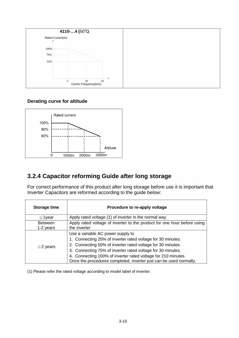
4110-…4 (50℃)
100%
70%
55%
5 10 16
Rated Current(In)
Carrier Frequency(kHz)
Derating curve for altitude
3.2.4 Capacitor reforming Guide after long storage For correct performance of this product after long storage before use it is important that Inverter Capacitors are reformed according to the guide below:
Storage time
Procedure to re-apply voltage
≦1year Apply rated voltage (1) of inverter in the normal way Between 1-2 years
Apply rated voltage of inverter to the product for one hour before using the inverter
≧2 years
Use a variable AC power supply to 1. Connecting 25% of inverter rated voltage for 30 minutes. 2. Connecting 50% of inverter rated voltage for 30 minutes. 3. Connecting 75% of inverter rated voltage for 30 minutes. 4. Connecting 100% of inverter rated voltage for 210 minutes. Once the procedures completed, inverter just can be used normally.
(1) Please refer the rated voltage according to model label of inverter.
3-11
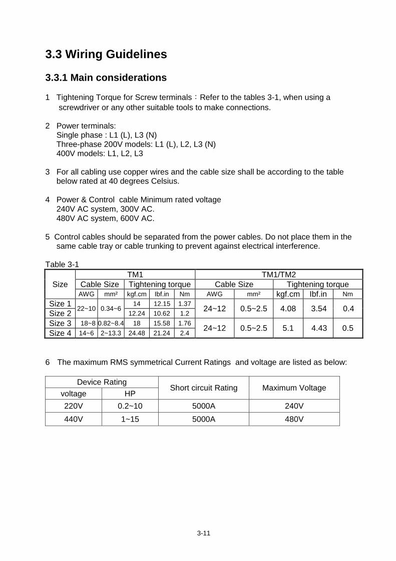
3.3 Wiring Guidelines 3.3.1 Main considerations 1 Tightening Torque for Screw terminals:Refer to the tables 3-1, when using a screwdriver or any other suitable tools to make connections. 2 Power terminals: Single phase : L1 (L), L3 (N) Three-phase 200V models: L1 (L), L2, L3 (N) 400V models: L1, L2, L3 3 For all cabling use copper wires and the cable size shall be according to the table below rated at 40 degrees Celsius.
4 Power & Control cable Minimum rated voltage 240V AC system, 300V AC. 480V AC system, 600V AC. 5 Control cables should be separated from the power cables. Do not place them in the same cable tray or cable trunking to prevent against electrical interference. Table 3-1
Size TM1 TM1/TM2
Cable Size Tightening torque Cable Size Tightening torque AWG mm² kgf.cm Ibf.in Nm AWG mm² kgf.cm Ibf.in Nm
Size 1 22~10 0.34~6 14 12.15 1.37 24~12 0.5~2.5 4.08 3.54 0.4 Size 2 12.24 10.62 1.2
Size 3 18~8 0.82~8.4 18 15.58 1.76 24~12 0.5~2.5 5.1 4.43 0.5 Size 4 14~6 2~13.3 24.48 21.24 2.4 6 The maximum RMS symmetrical Current Ratings and voltage are listed as below:
Device Rating
Short circuit Rating Maximum Voltage voltage HP 220V 0.2~10 5000A 240V 440V 1~15 5000A 480V

3-12
7 Electrical ratings of terminals:
Power (kW) Horsepower Supply voltage Specification Voltage (Volt) Current(A)
0.4 / 0.75 0.5 / 1 220~240V 300 30 1.5 / 2.2 2 / 3 220~240V 30
0.75 / 1.5 / 2.2 1 / 2 / 3 380~480V 600 28 3.7 5 220~240V 300 45
5.5 / 7.5 7.5 / 10 220~240V 300 65 3.7 / 5.5 5 / 7.5 380~480V 600 45 7.5 / 11 10 / 15 380~480V 600 65
3-13
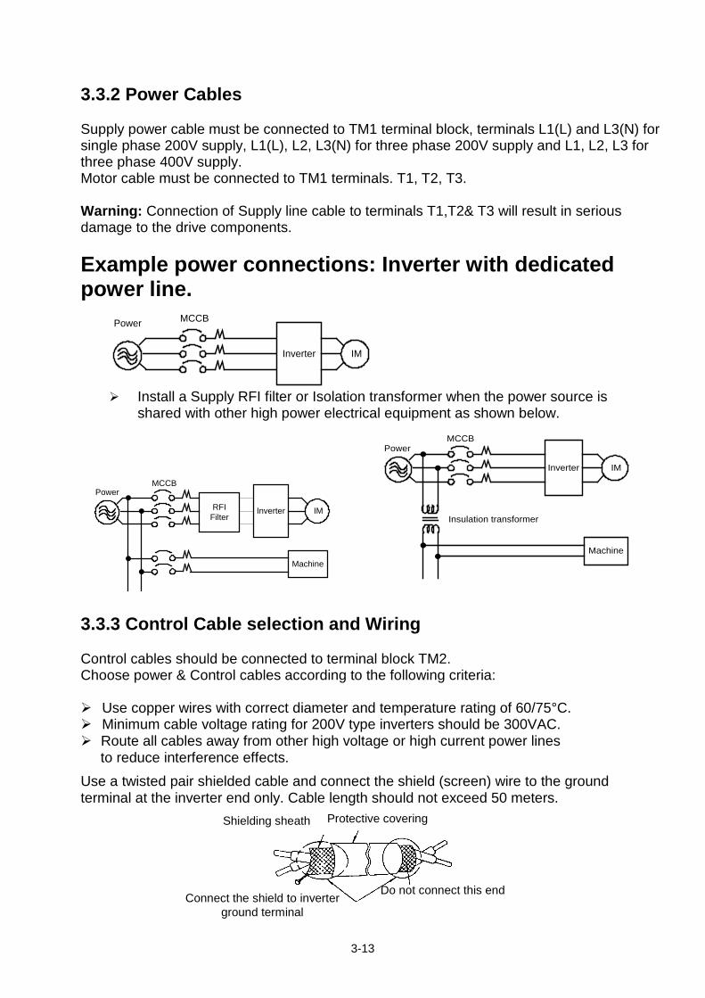
3.3.2 Power Cables Supply power cable must be connected to TM1 terminal block, terminals L1(L) and L3(N) for single phase 200V supply, L1(L), L2, L3(N) for three phase 200V supply and L1, L2, L3 for three phase 400V supply. Motor cable must be connected to TM1 terminals. T1, T2, T3. Warning: Connection of Supply line cable to terminals T1,T2& T3 will result in serious damage to the drive components. Example power connections: Inverter with dedicated power line.
Inverter IM
Power MCCB
Install a Supply RFI filter or Isolation transformer when the power source is
shared with other high power electrical equipment as shown below.
Inverter IM
Machine
Insulation transformer
Power MCCB
3.3.3 Control Cable selection and Wiring Control cables should be connected to terminal block TM2. Choose power & Control cables according to the following criteria: Use copper wires with correct diameter and temperature rating of 60/75°C. Minimum cable voltage rating for 200V type inverters should be 300VAC. Route all cables away from other high voltage or high current power lines
to reduce interference effects. Use a twisted pair shielded cable and connect the shield (screen) wire to the ground terminal at the inverter end only. Cable length should not exceed 50 meters.
Shielding sheath
Protective covering
Inverter IM
Machine
RFIFilter
Power MCCB
Connect the shield to inverter ground terminal
Do not connect this end
3-14
3.3.4 Wiring and EMC guidelines For effective interference suppression, do not route power and control cables in the same conduit or trunking. To prevent radiated noise, motor cable should be put in a metal conduit. Alternatively an armored or shielded type motor cable should be used. For effective suppression of noise emissions the cable armor or shield must be grounded at both ends to the motor and the inverter ground. These connections should be as short as possible. Motor cable and signal lines of other control equipment should be at the least 30 cm apart. BDI50-…-F series with built-in EMC filter All BDI50-…-F inverters are equipped with an internal EMC filter able to comply the performance levels required by EN 61800-3:2012 standard (category C2) with a maximum of 10 meters of shielded motor cable.
3-15
Typical Wiring
Drive
5 6
7
8
2
3
1
4
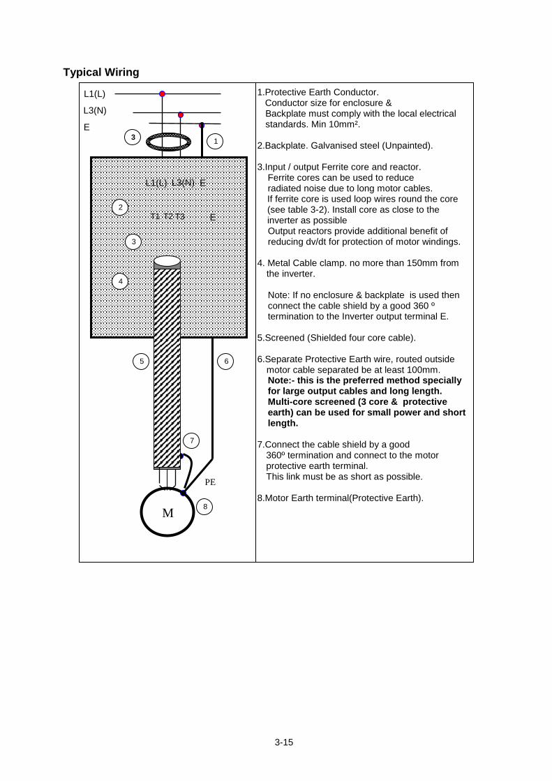
1.Protective Earth Conductor. Conductor size for enclosure & Backplate must comply with the local electrical standards. Min 10mm².
2.Backplate. Galvanised steel (Unpainted). 3.Input / output Ferrite core and reactor.
Ferrite cores can be used to reduce radiated noise due to long motor cables. If ferrite core is used loop wires round the core (see table 3-2). Install core as close to the inverter as possible Output reactors provide additional benefit of reducing dv/dt for protection of motor windings.
4. Metal Cable clamp. no more than 150mm from
the inverter.
Note: If no enclosure & backplate is used then connect the cable shield by a good 360 º termination to the Inverter output terminal E.
5.Screened (Shielded four core cable). 6.Separate Protective Earth wire, routed outside
motor cable separated be at least 100mm. Note:- this is the preferred method specially for large output cables and long length. Multi-core screened (3 core & protective earth) can be used for small power and short length.
7.Connect the cable shield by a good 360º termination and connect to the motor protective earth terminal. This link must be as short as possible.
8.Motor Earth terminal(Protective Earth).
L1(L)
PE
M
E T1 T2 T3
L3(N) E
L1(L) L3(N) E
3
3-16
3.3.5 Failure liability Gefran bears no responsibility for any failures or damaged caused to the inverter if the
recommendations in this instruction manual have not been followed specifically points listed below.
If a correctly rated fuse or circuit breaker has not been installed between the power
source and the inverter. If a magnetic contactor, a phase capacitor, burst absorber and LC or RC circuits have
been connected between the inverter and the motor. If an incorrectly rated three-phase squirrel cage induction motor has been used. Note:
When one inverter is driving several motors, the total current of all motors running simultaneously must be less than the rated current of the inverter, and each motor has to be equipped with a correctly rated thermal overload relay.
3-17
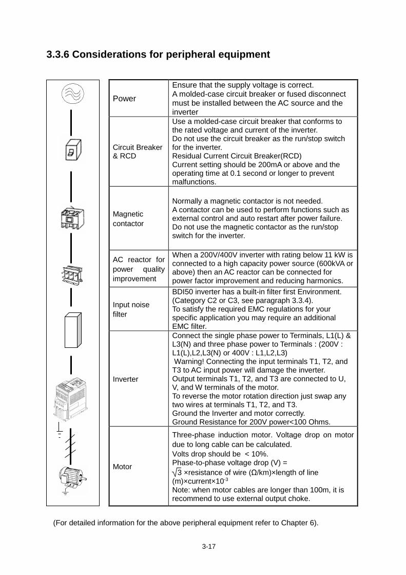
3.3.6 Considerations for peripheral equipment ( (For detailed information for the above peripheral equipment refer to Chapter 6).
Power
Ensure that the supply voltage is correct. A molded-case circuit breaker or fused disconnect must be installed between the AC source and the inverter
Circuit Breaker & RCD
Use a molded-case circuit breaker that conforms to the rated voltage and current of the inverter. Do not use the circuit breaker as the run/stop switch for the inverter. Residual Current Circuit Breaker(RCD) Current setting should be 200mA or above and the operating time at 0.1 second or longer to prevent malfunctions.
Magnetic contactor
Normally a magnetic contactor is not needed. A contactor can be used to perform functions such as external control and auto restart after power failure. Do not use the magnetic contactor as the run/stop switch for the inverter.
AC reactor for power quality improvement
When a 200V/400V inverter with rating below 11 kW is connected to a high capacity power source (600kVA or above) then an AC reactor can be connected for power factor improvement and reducing harmonics.
Input noise filter
BDI50 inverter has a built-in filter first Environment. (Category C2 or C3, see paragraph 3.3.4). To satisfy the required EMC regulations for your specific application you may require an additional EMC filter.
Inverter
Connect the single phase power to Terminals, L1(L) & L3(N) and three phase power to Terminals : (200V : L1(L),L2,L3(N) or 400V : L1,L2,L3) Warning! Connecting the input terminals T1, T2, and T3 to AC input power will damage the inverter. Output terminals T1, T2, and T3 are connected to U, V, and W terminals of the motor. To reverse the motor rotation direction just swap any two wires at terminals T1, T2, and T3. Ground the Inverter and motor correctly. Ground Resistance for 200V power<100 Ohms.
Motor
Three-phase induction motor. Voltage drop on motor due to long cable can be calculated. Volts drop should be < 10%. Phase-to-phase voltage drop (V) =
3 ×resistance of wire (Ω/km)×length of line (m)×current×10-3
Note: when motor cables are longer than 100m, it is recommend to use external output choke.
3-18
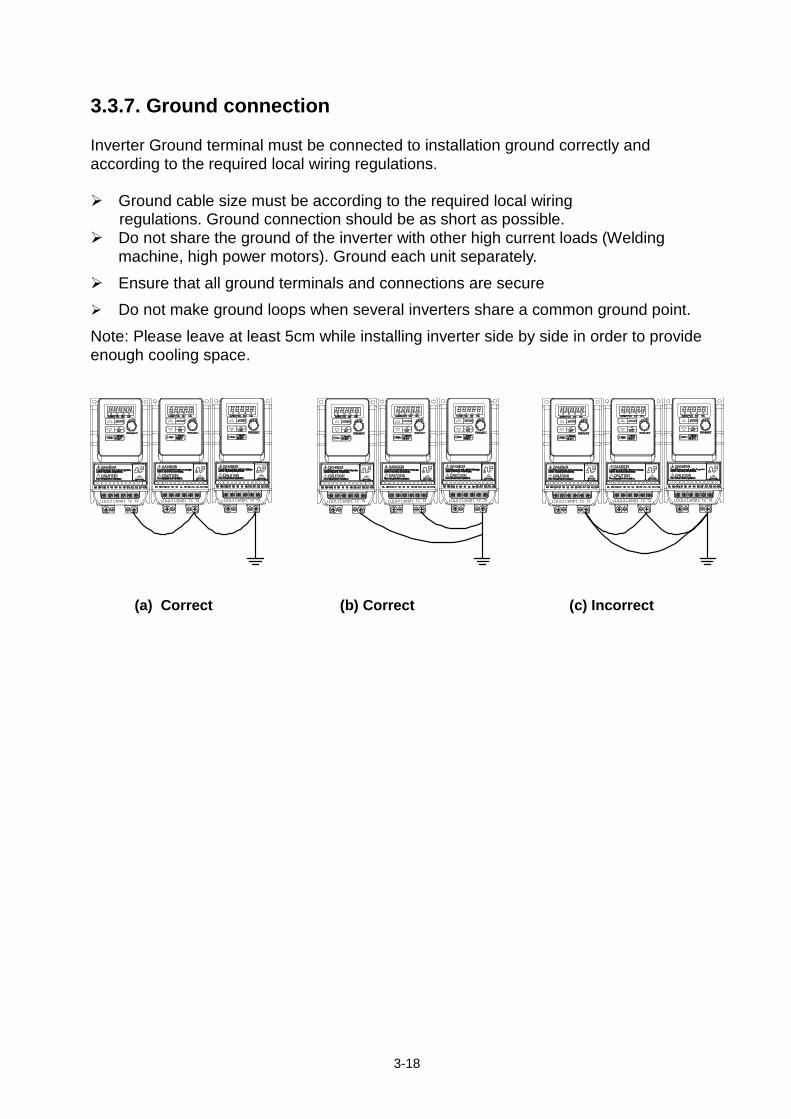
3.3.7. Ground connection Inverter Ground terminal must be connected to installation ground correctly and according to the required local wiring regulations. Ground cable size must be according to the required local wiring
regulations. Ground connection should be as short as possible. Do not share the ground of the inverter with other high current loads (Welding
machine, high power motors). Ground each unit separately.
Ensure that all ground terminals and connections are secure Do not make ground loops when several inverters share a common ground point.
Note: Please leave at least 5cm while installing inverter side by side in order to provide enough cooling space.
(a) Correct (b) Correct (c) Incorrect
L1(L) T1 T2 T3L3(N)L2 L1(L) T1 T2 T3L3(N)L2 L1(L) T1 T2 T3L3(N)L2 L1(L) T1 T2 T3L3(N)L2 L1(L) T1 T2 T3L3(N)L2 L1(L) T1 T2 T3L3(N)L2 L1(L) T1 T2 T3L3(N)L2 L1(L) T1 T2 T3L3(N)L2 L1(L) T1 T2 T3L3(N)L2
3-19
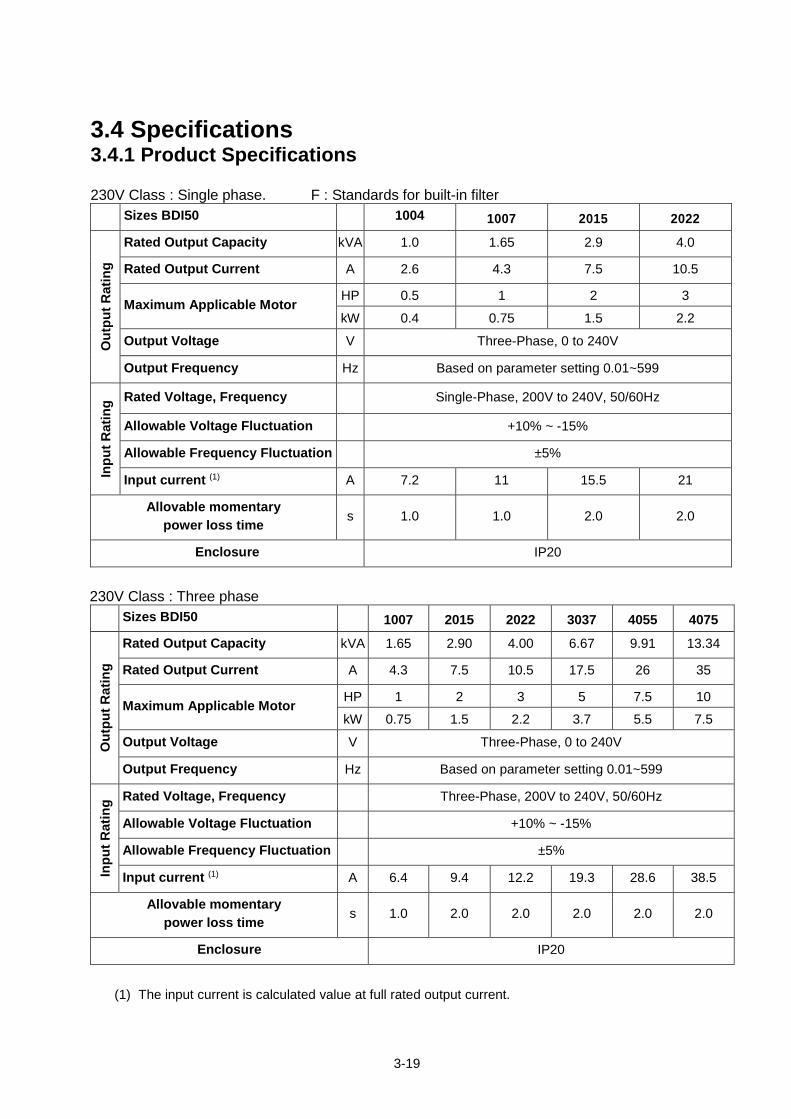
3.4 Specifications 3.4.1 Product Specifications 230V Class : Single phase. F : Standards for built-in filter
Sizes BDI50 1004 1007 2015 2022
Out
put R
atin
g
Rated Output Capacity kVA 1.0 1.65 2.9 4.0
Rated Output Current A 2.6 4.3 7.5 10.5
Maximum Applicable Motor HP 0.5 1 2 3
kW 0.4 0.75 1.5 2.2
Output Voltage V Three-Phase, 0 to 240V
Output Frequency Hz Based on parameter setting 0.01~599
Inpu
t Rat
ing Rated Voltage, Frequency Single-Phase, 200V to 240V, 50/60Hz
Allowable Voltage Fluctuation +10% ~ -15%
Allowable Frequency Fluctuation ±5%
Input current (1) A 7.2 11 15.5 21
Allovable momentary power loss time
s 1.0 1.0 2.0 2.0
Enclosure IP20
230V Class : Three phase
Sizes BDI50 1007 2015 2022 3037 4055 4075
Out
put R
atin
g
Rated Output Capacity kVA 1.65 2.90 4.00 6.67 9.91 13.34
Rated Output Current A 4.3 7.5 10.5 17.5 26 35
Maximum Applicable Motor HP 1 2 3 5 7.5 10
kW 0.75 1.5 2.2 3.7 5.5 7.5
Output Voltage V Three-Phase, 0 to 240V
Output Frequency Hz Based on parameter setting 0.01~599
Inpu
t Rat
ing Rated Voltage, Frequency Three-Phase, 200V to 240V, 50/60Hz
Allowable Voltage Fluctuation +10% ~ -15%
Allowable Frequency Fluctuation ±5%
Input current (1) A 6.4 9.4 12.2 19.3 28.6 38.5
Allovable momentary power loss time
s 1.0 2.0 2.0 2.0 2.0 2.0
Enclosure IP20
(1) The input current is calculated value at full rated output current.
3-20
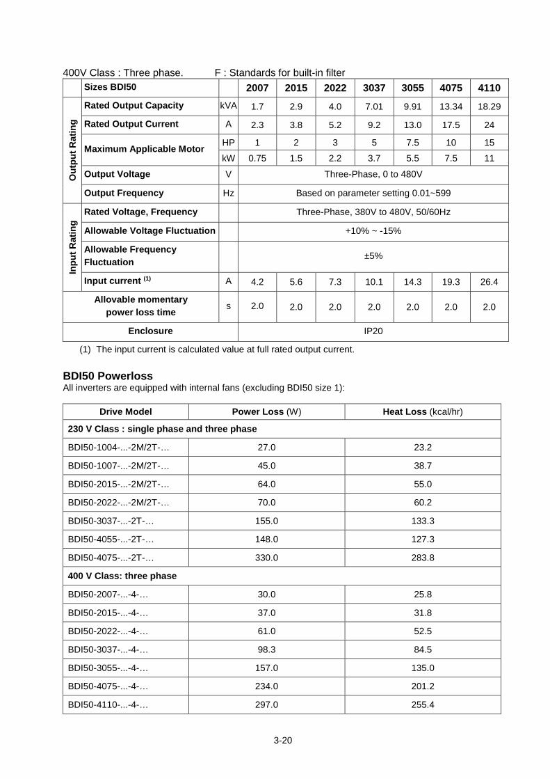
400V Class : Three phase. F : Standards for built-in filter Sizes BDI50 2007 2015 2022 3037 3055 4075 4110
Out
put R
atin
g
Rated Output Capacity kVA 1.7 2.9 4.0 7.01 9.91 13.34 18.29
Rated Output Current A 2.3 3.8 5.2 9.2 13.0 17.5 24
Maximum Applicable Motor HP 1 2 3 5 7.5 10 15
kW 0.75 1.5 2.2 3.7 5.5 7.5 11
Output Voltage V Three-Phase, 0 to 480V
Output Frequency Hz Based on parameter setting 0.01~599
Inpu
t Rat
ing
Rated Voltage, Frequency Three-Phase, 380V to 480V, 50/60Hz
Allowable Voltage Fluctuation +10% ~ -15%
Allowable Frequency Fluctuation ±5%
Input current (1) A 4.2 5.6 7.3 10.1 14.3 19.3 26.4
Allovable momentary power loss time s 2.0 2.0 2.0 2.0 2.0 2.0 2.0
Enclosure IP20
(1) The input current is calculated value at full rated output current. BDI50 Powerloss All inverters are equipped with internal fans (excluding BDI50 size 1):
Drive Model Power Loss (W) Heat Loss (kcal/hr)
230 V Class : single phase and three phase
BDI50-1004-...-2M/2T-… 27.0 23.2
BDI50-1007-...-2M/2T-… 45.0 38.7
BDI50-2015-...-2M/2T-… 64.0 55.0
BDI50-2022-...-2M/2T-… 70.0 60.2
BDI50-3037-...-2T-… 155.0 133.3
BDI50-4055-...-2T-… 148.0 127.3
BDI50-4075-...-2T-… 330.0 283.8
400 V Class: three phase
BDI50-2007-...-4-… 30.0 25.8
BDI50-2015-...-4-… 37.0 31.8
BDI50-2022-...-4-… 61.0 52.5
BDI50-3037-...-4-… 98.3 84.5
BDI50-3055-...-4-… 157.0 135.0
BDI50-4075-...-4-… 234.0 201.2
BDI50-4110-...-4-… 297.0 255.4
3-21
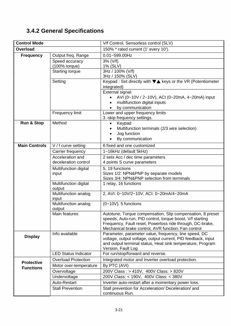
3.4.2 General Specifications
Control Mode V/f Control, Sensorless control (SLV) Overload 150% * rated current (1’ every 10’).
Frequency Output freq. Range 0.01~599.00Hz Speed accuracy (100% torque)
3% (V/f) 1% (SLV)
Starting torque 3Hz / 100% (V/f) 3Hz / 150% (SLV)
Setting Keypad : Set directly with ▼▲ keys or the VR (Potentiometer integrated) External signal:
• AVI (0~10V / 2~10V), ACI (0~20mA, 4~20mA) input • multifunction digital inputs • by communication
Frequency limit Lower and upper frequency limits 3 -skip frequency settings.
Run & Stop Method • Keypad • Multifunction terminals (2/3 wire selection) • Jog function • By communication
Main Controls V / f curve setting 6 fixed and one customized Carrier frequency 1~16kHz (default 5kHz) Acceleration and deceleration control
2 sets Acc / dec time parameters 4 points S curve parameters
Multifunction digital input
5, 19 functions Sizes 1/2: NPN&PNP by separate models Sizes 3/4: NPN&PNP selection from terminals
Multifunction digital output
1 relay, 16 functions
Multifunction analog input
2, AVI: 0~10V/2~10V, ACI: 0~20mA/4~20mA
Multifunction analog output
(0~10V), 5 functions
Main features Autotune, Torque compensation, Slip compensation, 8 preset speeds, Auto-run, PID control, torque boost, V/f starting Frequency, Fault reset, Powerloss ride through, DC-brake, Mechanical brake control, AVR function, Fan control
Display Info available Parameter, parameter value, frequency, line speed, DC voltage, output voltage, output current, PID feedback, input and output terminal status, Heat sink temperature, Program Version, Fault Log
LED Status Indicator For run/stop/forward and reverse.
Protective Functions
Overload Protection Integrated motor and Inverter overload protection. Motor over-temperature By PTC (AVI) Overvoltage 200V Class : > 410V, 400V Class: > 820V Undervoltage 200V Class: < 190V, 400V Class: < 380V Auto-Restart Inverter auto-restart after a momentary power loss. Stall Prevention Stall prevention for Acceleration/ Deceleration/ and
continuous Run.
3-22
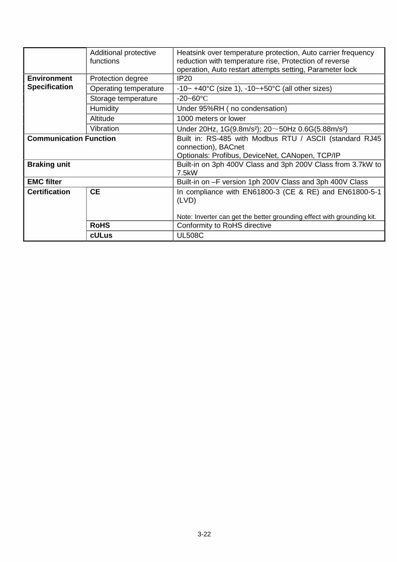
Additional protective functions
Heatsink over temperature protection, Auto carrier frequency reduction with temperature rise, Protection of reverse operation, Auto restart attempts setting, Parameter lock
Environment Specification
Protection degree IP20 Operating temperature -10~ +40°C (size 1), -10~+50°C (all other sizes) Storage temperature -20~60°C Humidity Under 95%RH ( no condensation) Altitude 1000 meters or lower Vibration Under 20Hz, 1G(9.8m/s²); 20~50Hz 0.6G(5.88m/s²)
Communication Function Built in: RS-485 with Modbus RTU / ASCII (standard RJ45 connection), BACnet Optionals: Profibus, DeviceNet, CANopen, TCP/IP
Braking unit Built-in on 3ph 400V Class and 3ph 200V Class from 3.7kW to 7.5kW
EMC filter Built-in on –F version 1ph 200V Class and 3ph 400V Class Certification CE In compliance with EN61800-3 (CE & RE) and EN61800-5-1
(LVD) Note: Inverter can get the better grounding effect with grounding kit.
RoHS Conformity to RoHS directive cULus UL508C
3-23
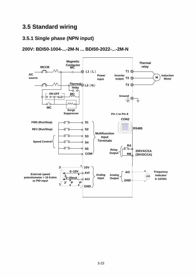
3.5 Standard wiring 3.5.1 Single phase (NPN input) 200V: BDI50-1004-...-2M-N ... BDI50-2022-...-2M-N
(MCCBL1(L)
ACsource
S2
S3
S4
AO3 +
250VAC/1A (30VDC/1A)
T1
T2
T3
RB
RAS5
L3(N)
(
ON-OFF
SurgeSuppressor
10V
AVI
ACI GND
MC
MagneticContactor
RS485
FWD (Run/Stop)
REV (Run/Stop)
Speed Control
External speed potentiometer = 10 Kohm
or PID input
Induction Motor
COM
MC
Thermal relay
MC
S1
GND
0~10V2 AO
+
-
Frequency Indicator0~10VDC
CON2
Thermal relay
M
0~20mAP P'2'1
-
RelayOutput
Pin 1 to Pin 8
Ground
Inverter output
Power input
AnalogOutput
Multifunction Input
Terminals
AnalogInput
3-24
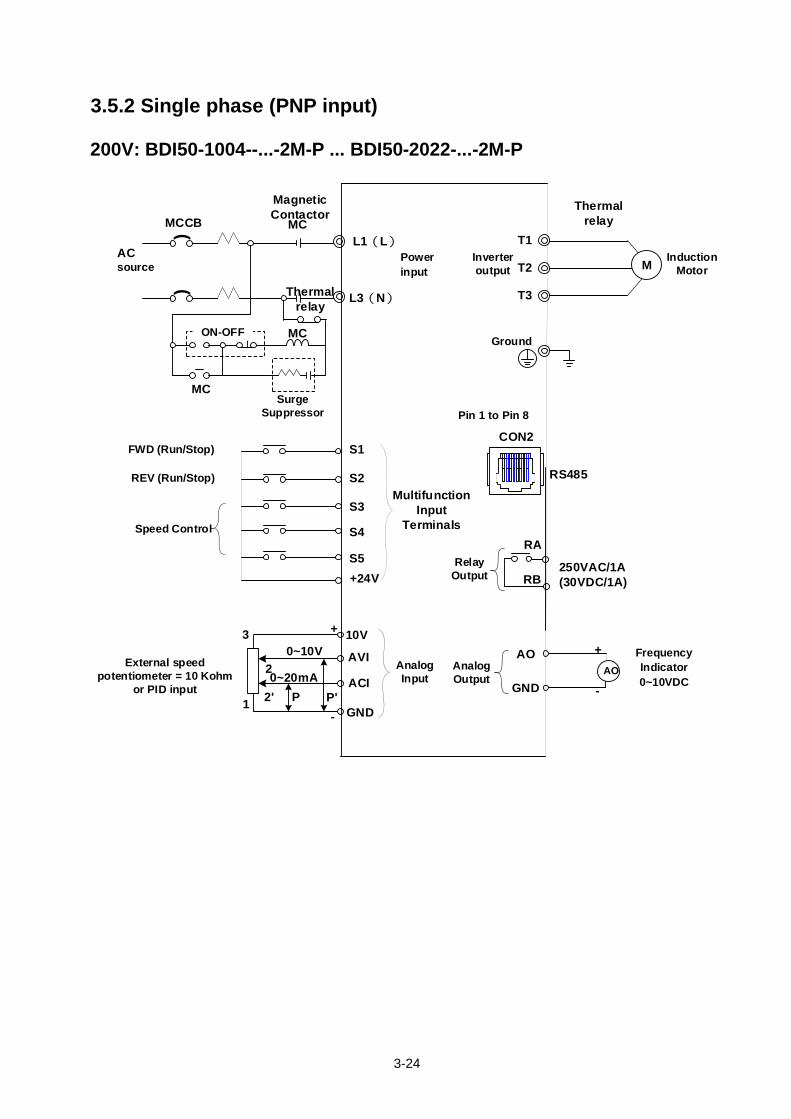
3.5.2 Single phase (PNP input) 200V: BDI50-1004--...-2M-P ... BDI50-2022-...-2M-P
(MCCBL1(L)
ACsource
S2
S3
S4
AO3 +
250VAC/1A (30VDC/1A)
T1
T2
T3
RB
RAS5
L3(N)
(
ON-OFF
SurgeSuppressor
10V
AVI
ACI GND
MC
MagneticContactor
RS485
FWD (Run/Stop)
REV (Run/Stop)
Speed Control
External speed potentiometer = 10 Kohm
or PID input
Induction Motor
+24V
MC
Thermal relay
MC
S1
GND
0~10V2 AO
+
-
Frequency Indicator0~10VDC
CON2
Thermal relay
M
0~20mAP P'2'1
-
RelayOutput
Pin 1 to Pin 8
Ground
Inverter output
Power input
AnalogOutput
Multifunction Input
Terminals
AnalogInput
3-25
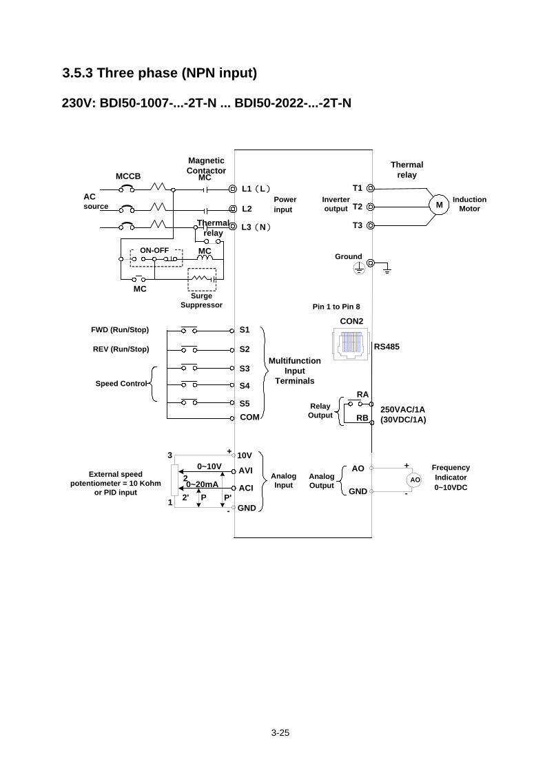
3.5.3 Three phase (NPN input) 230V: BDI50-1007-...-2T-N ... BDI50-2022-...-2T-N
(MCCBL1(L)
ACsource
S2
S3
S4
AO3 +
250VAC/1A (30VDC/1A)
T1
T2
T3
RB
RAS5
L3(N)
(
ON-OFF
SurgeSuppressor
10V
AVI
ACI GND
MC
MagneticContactor
RS485
FWD (Run/Stop)
REV (Run/Stop)
Speed Control
External speed potentiometer = 10 Kohm
or PID input
Induction Motor
COM
MC
Thermal relay
MC
S1
GND
0~10V2 AO
+
-
Frequency Indicator0~10VDC
CON2
Thermal relay
M
0~20mAP P'2'1
-
RelayOutput
Pin 1 to Pin 8
Ground
Inverter output
Power input
AnalogOutput
Multifunction Input
Terminals
AnalogInput
(
L2
3-26
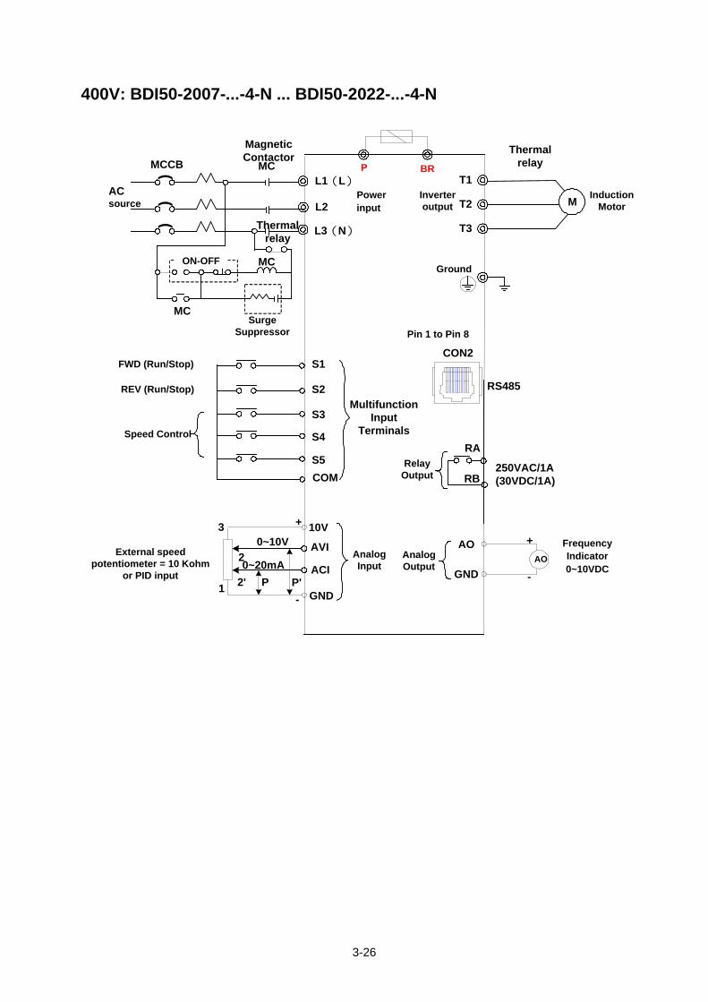
400V: BDI50-2007-...-4-N ... BDI50-2022-...-4-N
(MCCBL1(L)
ACsource
S2
S3
S4
AO3 +
250VAC/1A (30VDC/1A)
T1
T2
T3
RB
RAS5
L3(N)
(
ON-OFF
SurgeSuppressor
10V
AVI
ACI GND
MC
MagneticContactor
RS485
FWD (Run/Stop)
REV (Run/Stop)
Speed Control
External speed potentiometer = 10 Kohm
or PID input
Induction Motor
COM
MC
Thermal relay
MC
S1
GND
0~10V2 AO
+
-
Frequency Indicator0~10VDC
CON2
Thermal relay
M
0~20mAP P'2'1
-
RelayOutput
Pin 1 to Pin 8
Ground
Inverter output
Power input
AnalogOutput
Multifunction Input
Terminals
AnalogInput
(
L2
P BR
3-27
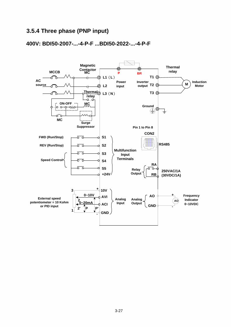
3.5.4 Three phase (PNP input) 400V: BDI50-2007-...-4-P-F ...BDI50-2022-...-4-P-F
(MCCBL1(L)
ACsource
S2
S3
S4
AO3 +
250VAC/1A (30VDC/1A)
T1
T2
T3
RB
RAS5
L3(N)
(
ON-OFF
SurgeSuppressor
10V
AVI
ACI GND
MC
MagneticContactor
RS485
FWD (Run/Stop)
REV (Run/Stop)
Speed Control
External speed potentiometer = 10 Kohm
or PID input
Induction Motor
+24V
MC
Thermal relay
MC
S1
GND
0~10V2 AO
+
-
Frequency Indicator0~10VDC
CON2
Thermal relay
M
0~20mAP P'2'1
-
RelayOutput
Pin 1 to Pin 8
Ground
Inverter output
Power input
AnalogOutput
Multifunction Input
Terminals
AnalogInput
(
L2
P BR
3-28
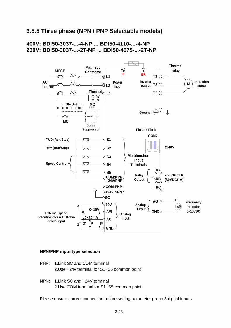
3.5.5 Three phase (NPN / PNP Selectable models) 400V: BDI50-3037-...-4-NP ... BDI50-4110-...-4-NP 230V: BDI50-3037-...-2T-NP ... BDI50-4075-...-2T-NP
(MCCBL1
ACsource
S2
S3
S4
AO3
+
250VAC/1A (30VDC/1A)
T1
T2
T3
RB
RAS5
L3
(
ON-OFF
SurgeSuppressor
10V
AVI
ACI
GND
MagneticContactor
RS485
FWD (Run/Stop)
REV (Run/Stop)
Speed Control
External speed potentiometer = 10 Kohm
or PID input
Induction Motor
COM:NPN
MC
Thermal relay
MC
S1
GND
0~10V2
AO
+
-
Frequency Indicator0~10VDC
CON2
Thermal relay
M
0~20mAP P'2'1
-
L2
(
+24V:NPN *RC
SC
COM:PNP+24V:PNP
Power input
P BR
Inverter output
Ground
Pin 1 to Pin 8
Multifunction Input
Terminals
RelayOutput
AnalogOutput
AnalogInput
NPN/PNP input type selection PNP: 1.Link SC and COM terminal
2.Use +24v terminal for S1~S5 common point NPN: 1.Link SC and +24V terminal
2.Use COM terminal for S1~S5 common point
Please ensure correct connection before setting parameter group 3 digital inputs.
3-29
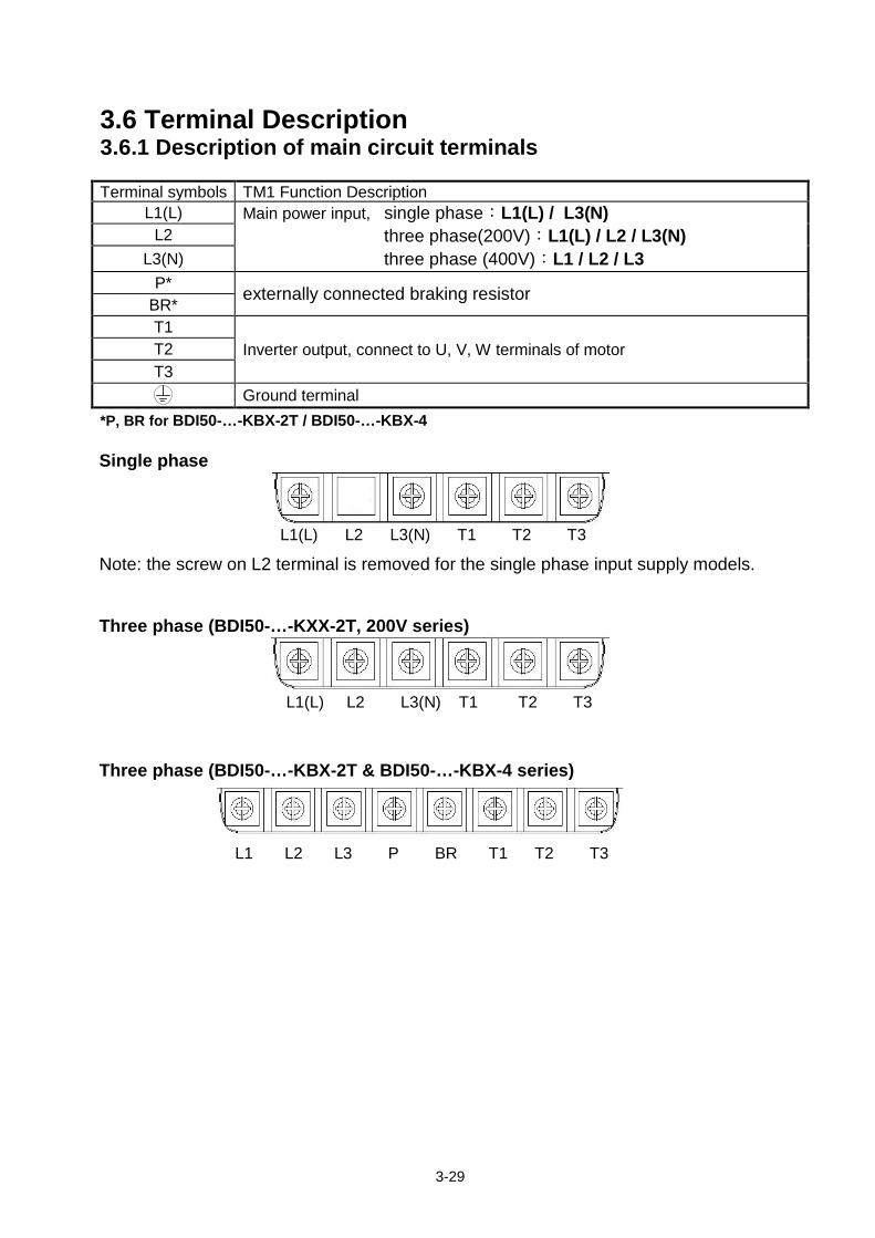
3.6 Terminal Description 3.6.1 Description of main circuit terminals Terminal symbols TM1 Function Description
L1(L) Main power input, single phase:L1(L) / L3(N) three phase(200V):L1(L) / L2 / L3(N) three phase (400V):L1 / L2 / L3
L2 L3(N)
P* externally connected braking resistor BR* T1
Inverter output, connect to U, V, W terminals of motor T2 T3
Ground terminal *P, BR for BDI50-…-KBX-2T / BDI50-…-KBX-4 Single phase
Note: the screw on L2 terminal is removed for the single phase input supply models. Three phase (BDI50-…-KXX-2T, 200V series)
Three phase (BDI50-…-KBX-2T & BDI50-…-KBX-4 series)
L1(L) L2 L3(N) T1 T2 T3
L1(L) L2 L3(N) T1 T2 T3
L1 L2 L3 P BR T1 T2 T3
3-30
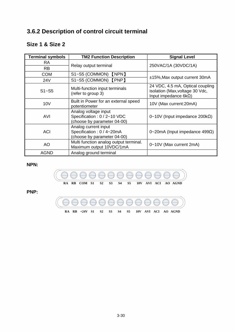
3.6.2 Description of control circuit terminal Size 1 & Size 2 Terminal symbols TM2 Function Description Signal Level
RA Relay output terminal 250VAC/1A (30VDC/1A)
RB COM S1~S5 (COMMON) 【NPN】
±15%,Max output current 30mA 24V S1~S5 (COMMON) 【PNP】
S1~S5 Multi-function input terminals (refer to group 3)
24 VDC, 4.5 mA, Optical coupling isolation (Max,voltage 30 Vdc, Input impedance 6kΩ)
10V Built in Power for an external speed potentiometer 10V (Max current:20mA)
AVI Analog voltage input Specification : 0 / 2~10 VDC (choose by parameter 04-00)
0~10V (Input impedance 200kΩ)
ACI Analog current input Specification : 0 / 4~20mA (choose by parameter 04-00)
0~20mA (Input impedance 499Ω)
AO Multi function analog output terminal. Maximum output 10VDC/1mA 0~10V (Max current 2mA)
AGND Analog ground terminal NPN:
RA RB COM S1 S2 S3 S4 S5 10V AVI ACI AO AGND
PNP:
RA RB +24V S1 S2 S3 S4 S5 10V AVI ACI AO AGND
3-31
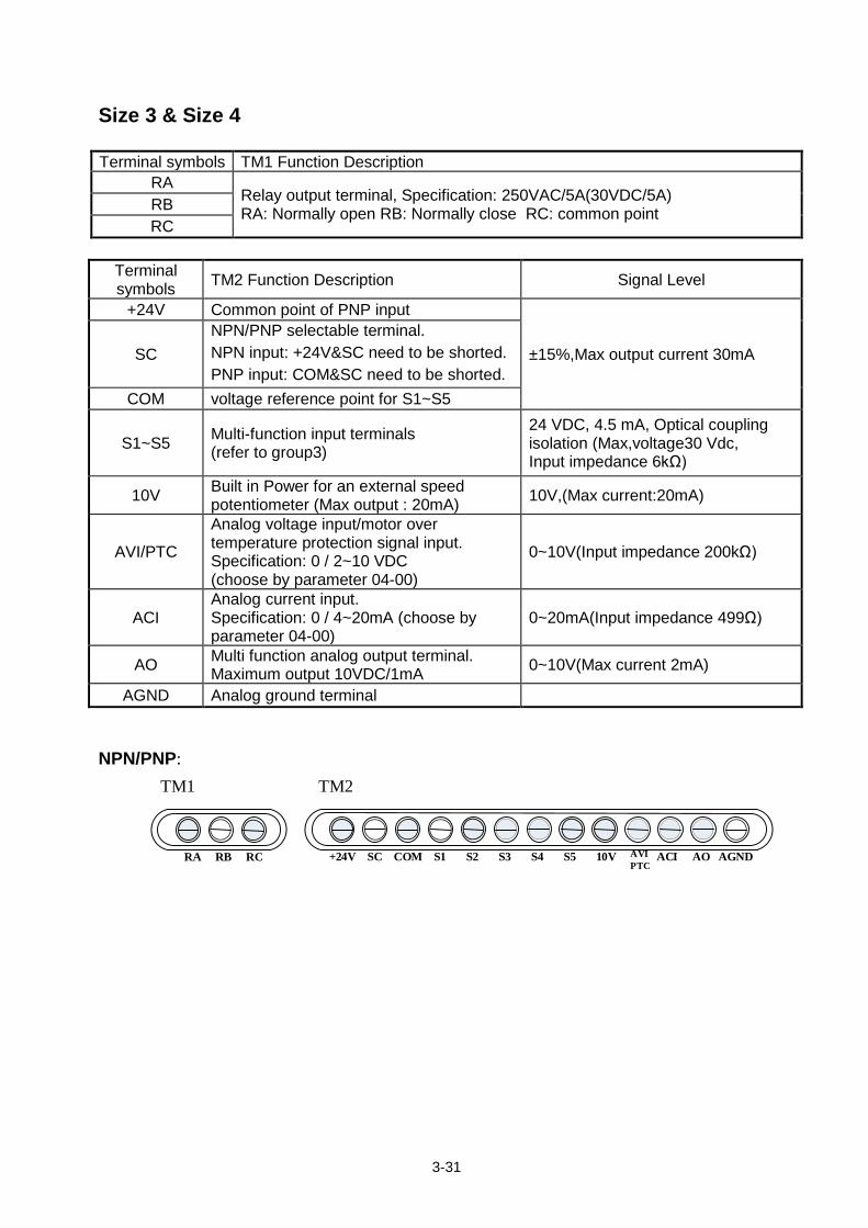
Size 3 & Size 4 Terminal symbols TM1 Function Description
RA Relay output terminal, Specification: 250VAC/5A(30VDC/5A) RA: Normally open RB: Normally close RC: common point RB
RC
Terminal symbols TM2 Function Description Signal Level
+24V Common point of PNP input
±15%,Max output current 30mA SC NPN/PNP selectable terminal. NPN input: +24V&SC need to be shorted. PNP input: COM&SC need to be shorted.
COM voltage reference point for S1~S5
S1~S5 Multi-function input terminals (refer to group3)
24 VDC, 4.5 mA, Optical coupling isolation (Max,voltage30 Vdc, Input impedance 6kΩ)
10V Built in Power for an external speed potentiometer (Max output : 20mA) 10V,(Max current:20mA)
AVI/PTC
Analog voltage input/motor over temperature protection signal input. Specification: 0 / 2~10 VDC (choose by parameter 04-00)
0~10V(Input impedance 200kΩ)
ACI Analog current input. Specification: 0 / 4~20mA (choose by parameter 04-00)
0~20mA(Input impedance 499Ω)
AO Multi function analog output terminal. Maximum output 10VDC/1mA 0~10V(Max current 2mA)
AGND Analog ground terminal NPN/PNP:
+24V SC COM S1 S2 S3 S4 S5 10V ACI AO AGND RA RB RC
TM1 TM2
AVIPTC
3-32
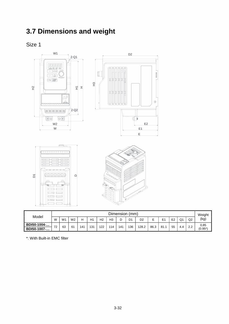
3.7 Dimensions and weight Size 1
DD1
W1
WW2
D2
E
E1E2
HH1
H2 H
3
2-Q1
2-Q2
Model Dimension (mm) Weight
(kg) W W1 W2 H H1 H2 H3 D D1 D2 E E1 E2 Q1 Q2
BDI50-1004-… 72 63 61 141 131 122 114 141 136 128.2 86.3 81.1 55 4.4 2.2 0,85 (0.95*) BDI50-1007-…
*: With Built-in EMC filter
3-33
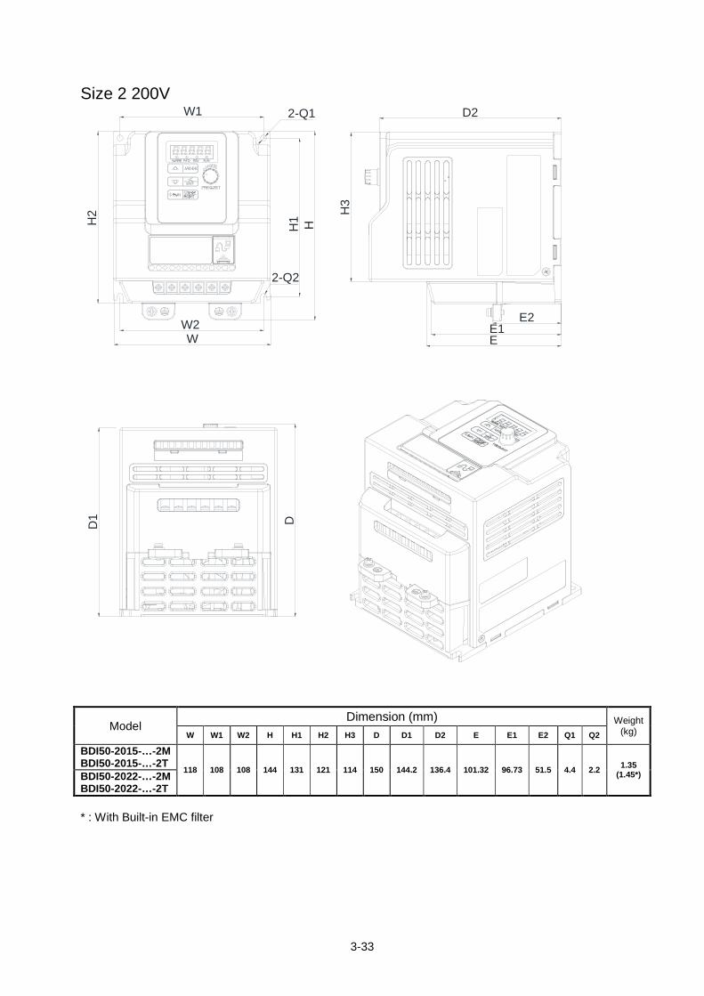
Size 2 200V
W
H2
W1
H1
D1 D
W2H
2-Q1
2-Q2
D2
H3
EE1
E2
Model Dimension (mm) Weight
(kg) W W1 W2 H H1 H2 H3 D D1 D2 E E1 E2 Q1 Q2
BDI50-2015-…-2M BDI50-2015-…-2T
118 108 108 144 131 121 114 150 144.2 136.4 101.32 96.73 51.5 4.4 2.2 1.35 (1.45*) BDI50-2022-…-2M
BDI50-2022-…-2T * : With Built-in EMC filter
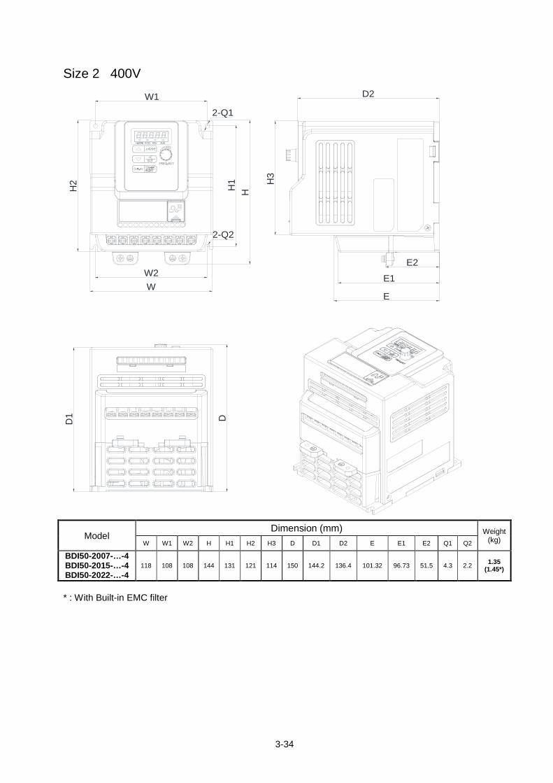
3-34
Size 2 400V D
1 D
W1
HH1
H2 H
3
WW2
D2
E
E1
E2
2-Q1
2-Q2
Model
Dimension (mm) Weight (kg) W W1 W2 H H1 H2 H3 D D1 D2 E E1 E2 Q1 Q2
BDI50-2007-…-4 BDI50-2015-…-4 BDI50-2022-…-4
118 108 108 144 131 121 114 150 144.2 136.4 101.32 96.73 51.5 4.3 2.2 1.35 (1.45*)
* : With Built-in EMC filter
3-35
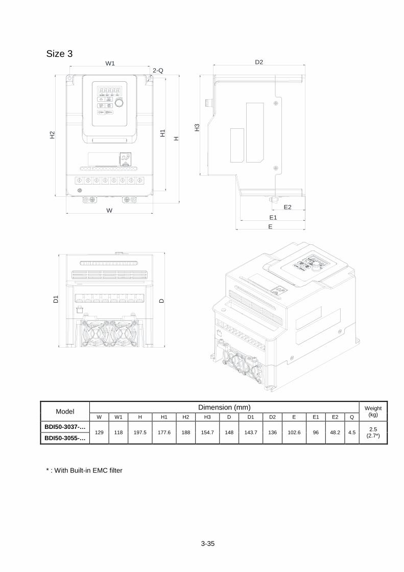
Size 3
H1
HH2
DD1
H3
W1
W
D2
EE1
E2
2-Q
Model Dimension (mm) Weight
(kg) W W1 H H1 H2 H3 D D1 D2 E E1 E2 Q
BDI50-3037-… 129 118 197.5 177.6 188 154.7 148 143.7 136 102.6 96 48.2 4.5 2.5
(2.7*) BDI50-3055-…
* : With Built-in EMC filter
3-36
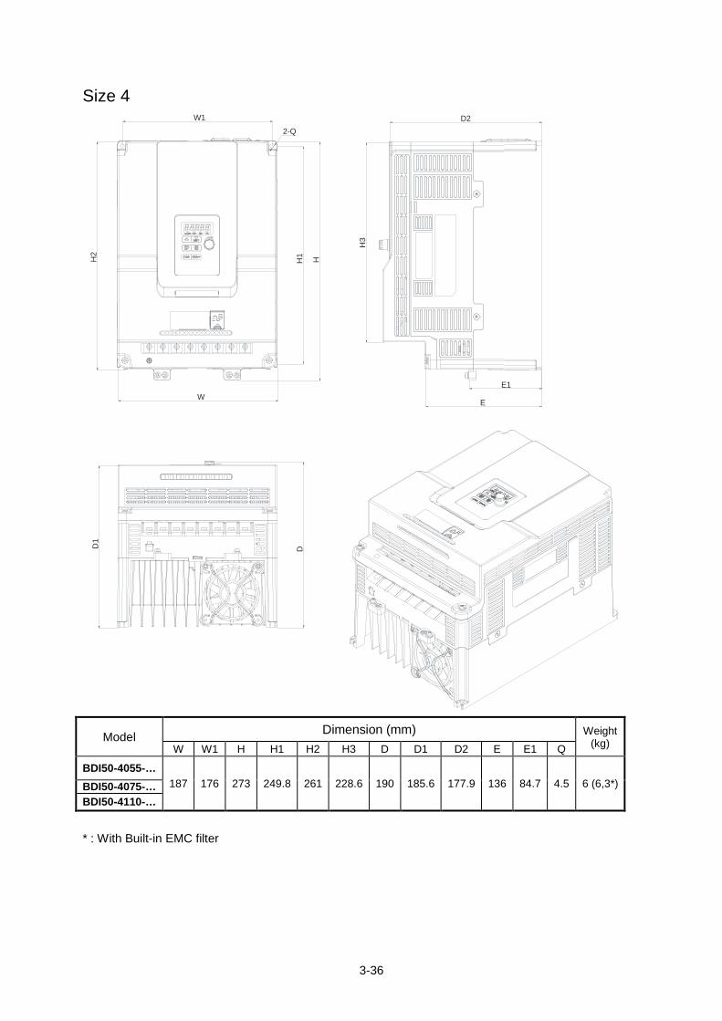
Size 4 W1
H1
D
W
D2
E
E1
D1
H2
H
H3
2-Q
Model Dimension (mm) Weight
(kg) W W1 H H1 H2 H3 D D1 D2 E E1 Q
BDI50-4055-… 187 176 273 249.8 261 228.6 190 185.6 177.9 136 84.7 4.5 6 (6,3*) BDI50-4075-…
BDI50-4110-…
* : With Built-in EMC filter
3-37
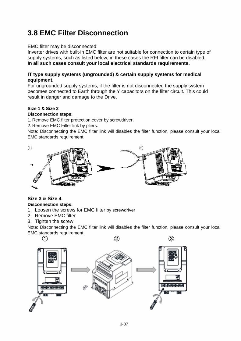
3.8 EMC Filter Disconnection EMC filter may be disconnected: Inverter drives with built-in EMC filter are not suitable for connection to certain type of supply systems, such as listed below; in these cases the RFI filter can be disabled. In all such cases consult your local electrical standards requirements. IT type supply systems (ungrounded) & certain supply systems for medical equipment. For ungrounded supply systems, if the filter is not disconnected the supply system becomes connected to Earth through the Y capacitors on the filter circuit. This could result in danger and damage to the Drive. Size 1 & Size 2 Disconnection steps: 1. Remove EMC filter protection cover by screwdriver. 2. Remove EMC Filter link by pliers. Note: Disconnecting the EMC filter link will disables the filter function, please consult your local EMC standards requirement. ① ②
Size 3 & Size 4 Disconnection steps: 1. Loosen the screws for EMC filter by screwdriver 2. Remove EMC filter 3. Tighten the screw Note: Disconnecting the EMC filter link will disables the filter function, please consult your local EMC standards requirement.
4-1
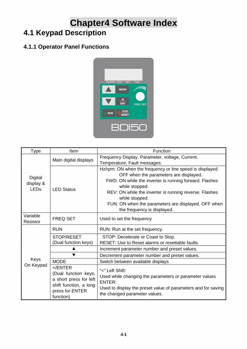
Chapter4 Software Index 4.1 Keypad Description 4.1.1 Operator Panel Functions
Type Item Function
Digital display &
LEDs
Main digital displays Frequency Display, Parameter, voltage, Current, Temperature, Fault messages.
LED Status
Hz/rpm: ON when the frequency or line speed is displayed. OFF when the parameters are displayed.
FWD: ON while the inverter is running forward. Flashes while stopped.
REV: ON while the inverter is running reverse. Flashes while stopped.
FUN: ON when the parameters are displayed. OFF when the frequency is displayed.
Variable Resistor FREQ SET Used to set the frequency
Keys On Keypad
RUN RUN: Run at the set frequency.
STOP/RESET (Dual function keys)
STOP: Decelerate or Coast to Stop. RESET: Use to Reset alarms or resettable faults.
▲ Increment parameter number and preset values. ▼ Decrement parameter number and preset values.
MODE Switch between available displays </ENTER (Dual function keys, a short press for left shift function, a long press for ENTER function)
“<” Left Shift: Used while changing the parameters or parameter values ENTER: Used to display the preset value of parameters and for saving the changed parameter values.
4-2
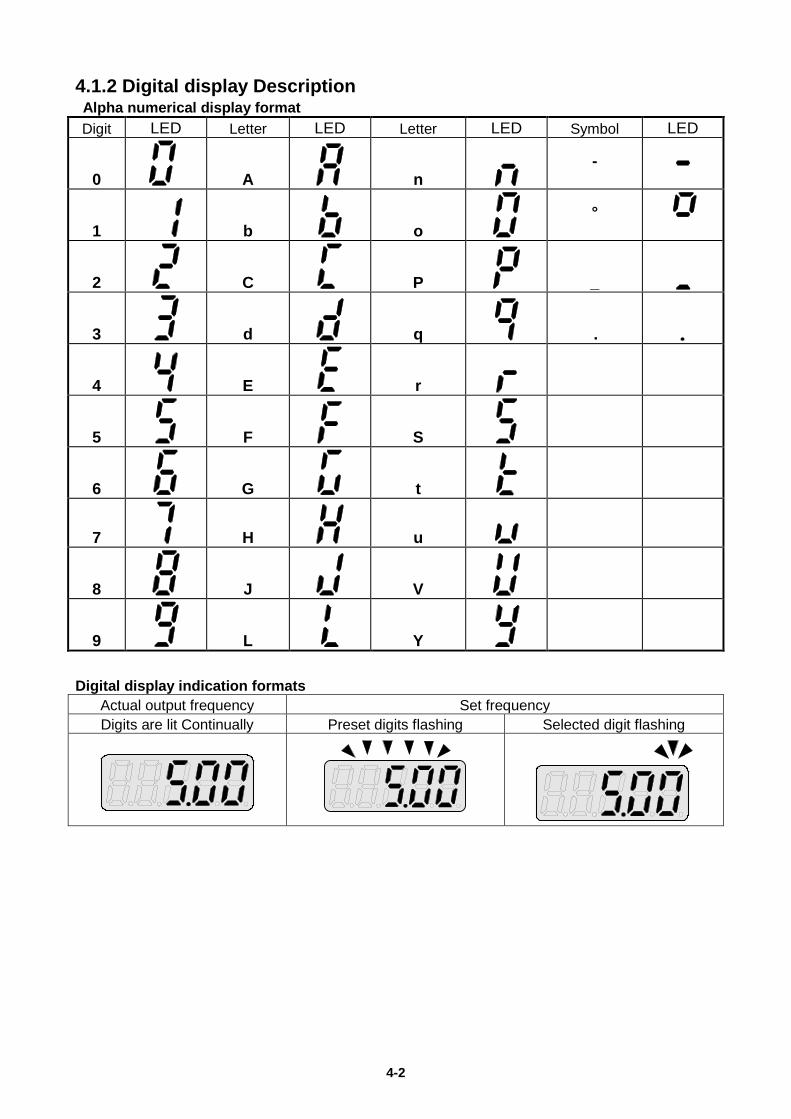
4.1.2 Digital display Description Alpha numerical display format Digit LED Letter LED Letter LED Symbol LED
0 A n -
1 b o °
2 C P _
3 d q .
4 E r
5 F S
6 G t
7 H u
8 J V
9 L Y Digital display indication formats
Actual output frequency Set frequency Digits are lit Continually Preset digits flashing Selected digit flashing
4-3
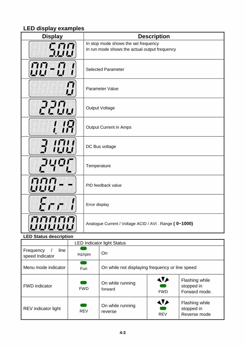
LED display examples
Display Description
In stop mode shows the set frequency In run mode shows the actual output frequency
Selected Parameter
Parameter Value
Output Voltage
Output Current in Amps
DC Bus voltage
Temperature
PID feedback value
Error display
Analogue Current / Voltage ACID / AVI . Range ( 0~1000)
LED Status description LED Indicator light Status Frequency / line speed Indicator Hz/RPM
On
Menu mode indicator FUN
On while not displaying frequency or line speed
FWD indicator
FWD
On while running forward FWD
Flashing while stopped in Forward mode.
REV indicator light
REV
On while running reverse REV
Flashing while stopped in Reverse mode
Hz/rpm
Fun
FWD
REV
FWD
REV
4-4
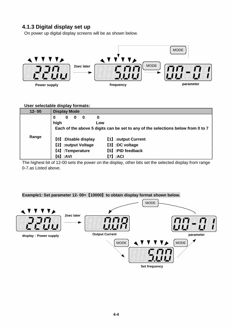
4.1.3 Digital display set up On power up digital display screens will be as shown below.
MODE
2sec later
Power supply frequency parameter
MODE
User selectable display formats: 12- 00 Display Mode
Range
0 0 0 0 0 high Low Each of the above 5 digits can be set to any of the selections below from 0 to 7 【0】:Disable display 【1】:output Current 【2】:output Voltage 【3】:DC voltage 【4】:Temperature 【5】:PID feedback 【6】:AVI 【7】:ACI
The highest bit of 12-00 sets the power on the display, other bits set the selected display from range 0-7.as Listed above. Example1: Set parameter 12- 00=【10000】to obtain display format shown below.
MODE
MODE MODE
2sec later
display:Power supply Output Current
Set frequency
parameter
4-5
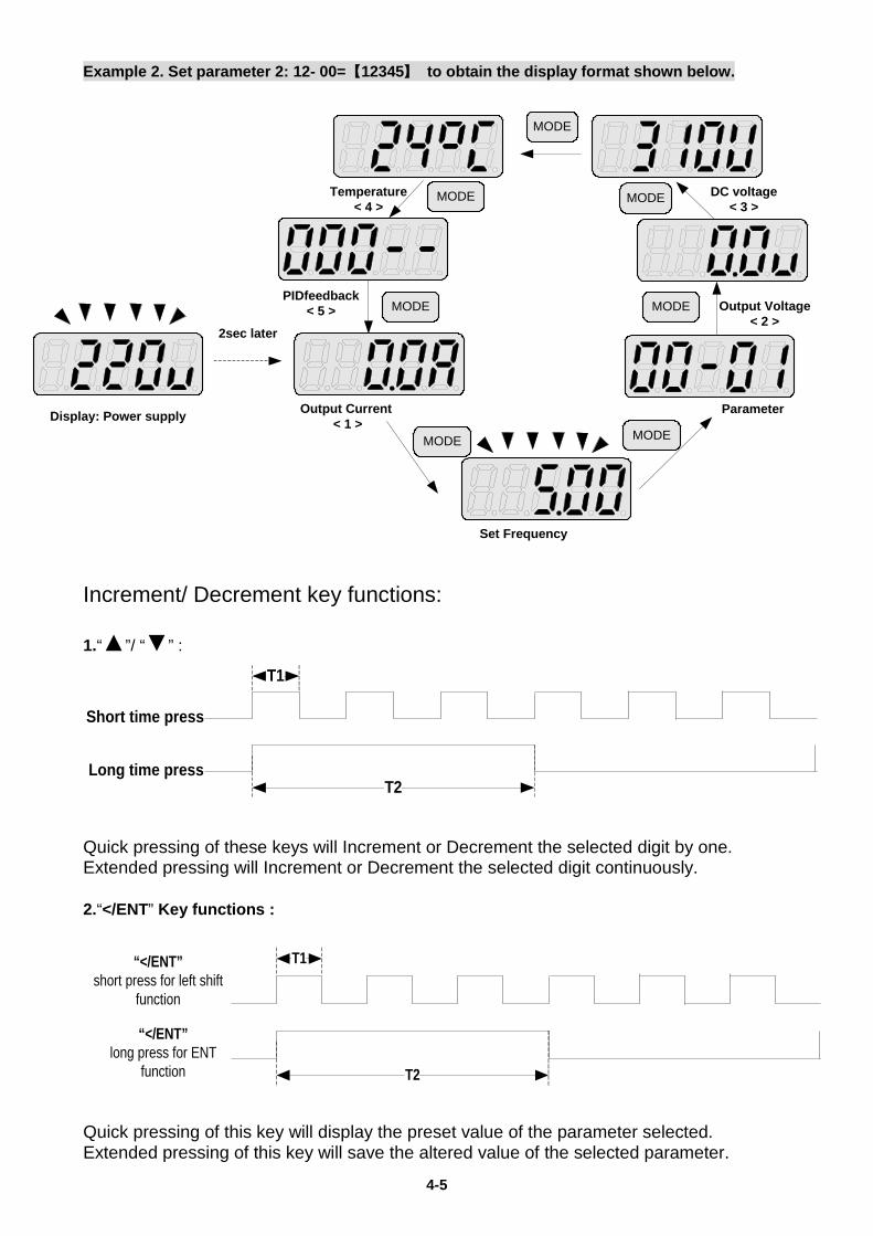
Example 2. Set parameter 2: 12- 00=【12345】 to obtain the display format shown below.
MODE MODE
2sec later
MODE
MODE
MODE
MODE
MODE
Temperature< 4 >
PIDfeedback< 5 >
Output Current < 1 >
Parameter
DC voltage< 3 >
Output Voltage< 2 >
Set Frequency
Display: Power supply
Increment/ Decrement key functions: 1.“▲”/ “▼” :
Short time press
Long time press
T1
T2
Quick pressing of these keys will Increment or Decrement the selected digit by one. Extended pressing will Increment or Decrement the selected digit continuously. 2.“</ENT” Key functions :
“</ENT”short press for left shift
function
“</ENT”long press for ENT
function
T1
T2
Quick pressing of this key will display the preset value of the parameter selected. Extended pressing of this key will save the altered value of the selected parameter.
4-6
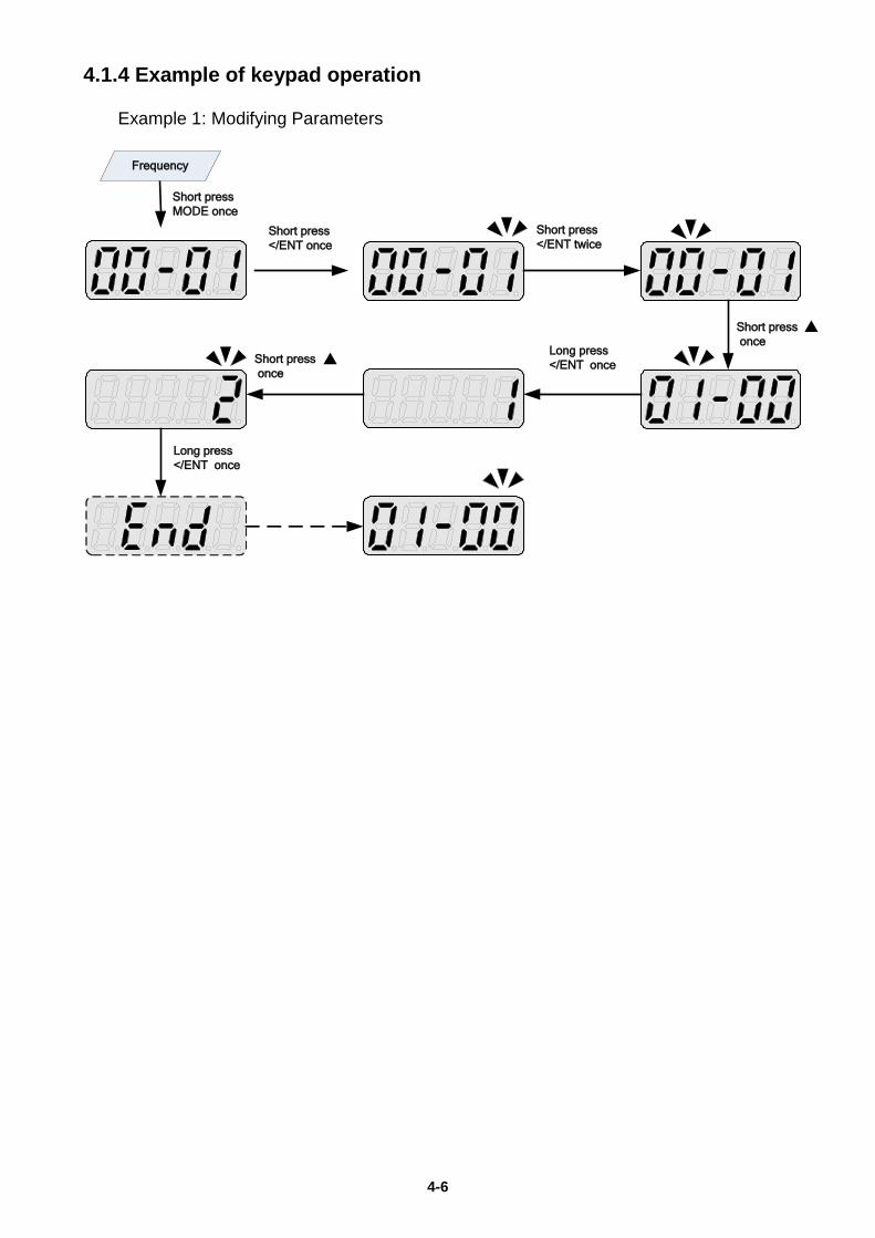
4.1.4 Example of keypad operation Example 1: Modifying Parameters
Short press</ENT once
Short press</ENT twice
Short press once
Long press</ENT once
Frequency
Short press once
Long press</ENT once
Short pressMODE once
▲
▲
4-7
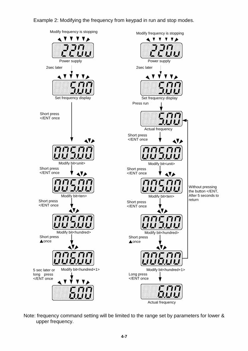
Example 2: Modifying the frequency from keypad in run and stop modes.
Modify frequency in stopping Modify frequency in operating
2sec later 2sec later
Short time press</ENT once
Press RUN
5sec lateror long time press</ENT once
Long time press</ENT once
Without pressing the button</ENT,After 5 seconds to return
Short time press</ENT once
Power Supply Power supply
Actual frequency
Actual frequency
Short time press</ENT once
Short time press</ENT once
Short time press
▲ once
Short time press</ENT once
Short time press</ENT once
Short time press
▲ once
Set frequency display Set frequency display
Modify bit<unit>
Modify bit<ten>
Modify bit<hundred>
Modify bit<hundred+1> Modify bit<hundred+1>
Modify bit<hundred>
Modify bit<ten>
Modify bit<unit>
Note: frequency command setting will be limited to the range set by parameters for lower &
upper frequency.
Modify frequency is stopping Modify frequency is stopping
Power supply Power supply
2sec later 2sec later
Set frequency display Set frequency display Press run
Short press </ENT once
Short press </ENT once
Actual frequency
Short press </ENT once
Short press </ENT once
Short press </ENT once
Short press </ENT once
Short press ▲once
Short press ▲once
5 sec later or long press </ENT once Long press
</ENT once
Modify bit<unit> Modify bit<unit>
Modify bit<ten> Modify bit<ten>
Modify bit<hundred> Modify bit<hundred>
Modify bit<hundred+1> Modify bit<hundred+1>
Actual frequency
Without pressing the button </ENT, After 5 seconds to return
4-8
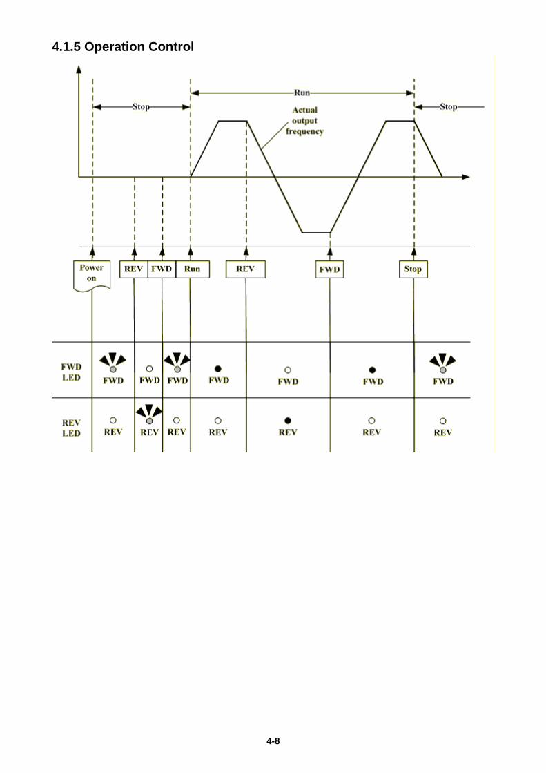
4.1.5 Operation Control
4-9
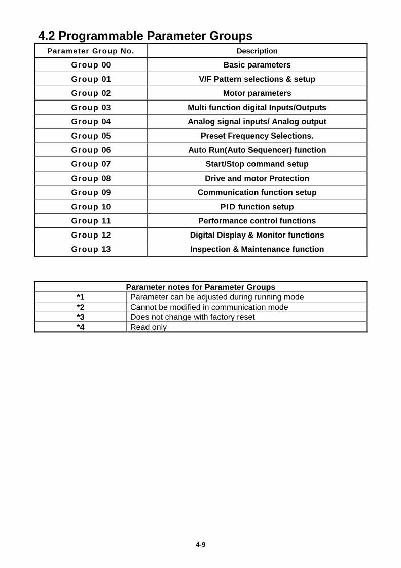
4.2 Programmable Parameter Groups Parameter Group No. Description
Group 00 Basic parameters
Group 01 V/F Pattern selections & setup
Group 02 Motor parameters
Group 03 Multi function digital Inputs/Outputs
Group 04 Analog signal inputs/ Analog output
Group 05 Preset Frequency Selections.
Group 06 Auto Run(Auto Sequencer) function
Group 07 Start/Stop command setup
Group 08 Drive and motor Protection
Group 09 Communication function setup
Group 10 PID function setup
Group 11 Performance control functions
Group 12 Digital Display & Monitor functions
Group 13 Inspection & Maintenance function
Parameter notes for Parameter Groups *1 Parameter can be adjusted during running mode *2 Cannot be modified in communication mode *3 Does not change with factory reset *4 Read only
4-10
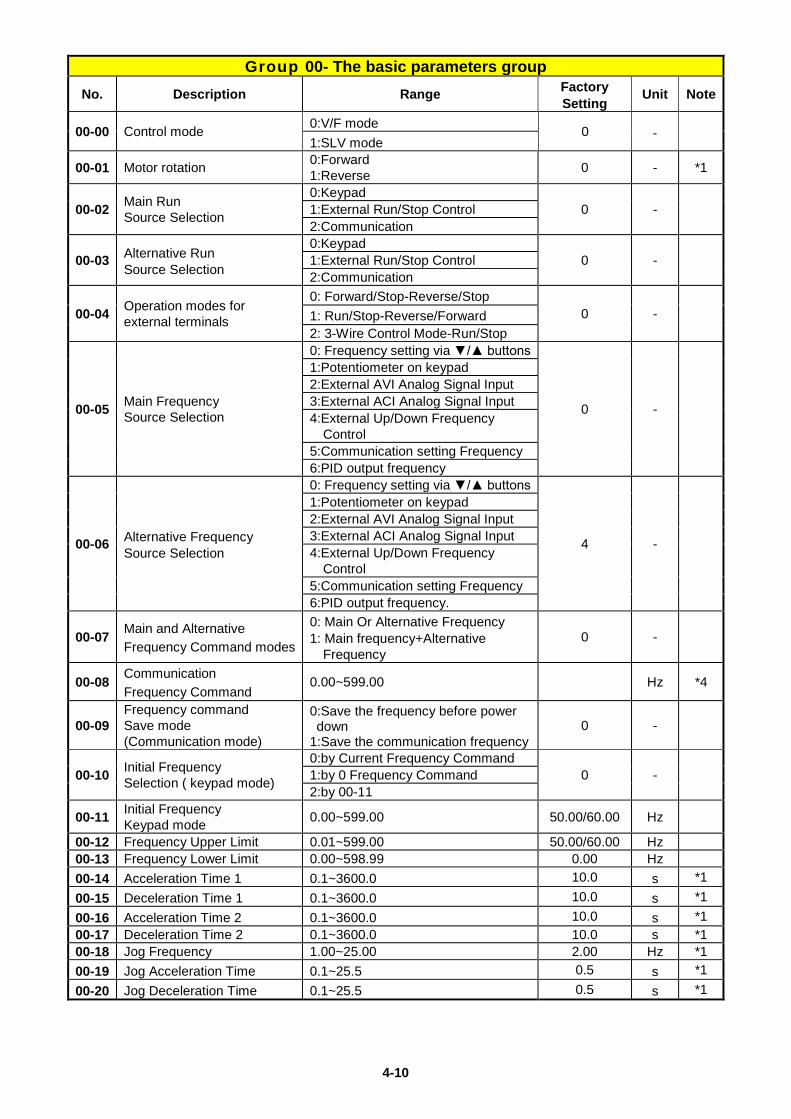
Group 00- The basic parameters group No. Description Range Factory
Setting Unit Note
00-00 Control mode 0:V/F mode 0 - 1:SLV mode
00-01 Motor rotation 0:Forward 1:Reverse 0 - *1
00-02 Main Run Source Selection
0:Keypad 0 - 1:External Run/Stop Control
2:Communication
00-03 Alternative Run Source Selection
0:Keypad 0 - 1:External Run/Stop Control
2:Communication
00-04 Operation modes for external terminals
0: Forward/Stop-Reverse/Stop 0 - 1: Run/Stop-Reverse/Forward
2: 3-Wire Control Mode-Run/Stop
00-05 Main Frequency Source Selection
0: Frequency setting via ▼/▲ buttons
0 -
1:Potentiometer on keypad 2:External AVI Analog Signal Input 3:External ACI Analog Signal Input 4:External Up/Down Frequency
Control 5:Communication setting Frequency 6:PID output frequency
00-06 Alternative Frequency Source Selection
0: Frequency setting via ▼/▲ buttons
4 -
1:Potentiometer on keypad 2:External AVI Analog Signal Input 3:External ACI Analog Signal Input 4:External Up/Down Frequency
Control 5:Communication setting Frequency 6:PID output frequency.
00-07 Main and Alternative Frequency Command modes
0: Main Or Alternative Frequency 1: Main frequency+Alternative
Frequency 0 -
00-08 Communication Frequency Command
0.00~599.00 Hz *4
00-09 Frequency command Save mode (Communication mode)
0:Save the frequency before power down
1:Save the communication frequency 0 -
00-10 Initial Frequency Selection ( keypad mode)
0:by Current Frequency Command 0 - 1:by 0 Frequency Command
2:by 00-11
00-11 Initial Frequency Keypad mode 0.00~599.00 50.00/60.00 Hz
00-12 Frequency Upper Limit 0.01~599.00 50.00/60.00 Hz 00-13 Frequency Lower Limit 0.00~598.99 0.00 Hz 00-14 Acceleration Time 1 0.1~3600.0 10.0 s *1 00-15 Deceleration Time 1 0.1~3600.0 10.0 s *1 00-16 Acceleration Time 2 0.1~3600.0 10.0 s *1 00-17 Deceleration Time 2 0.1~3600.0 10.0 s *1 00-18 Jog Frequency 1.00~25.00 2.00 Hz *1 00-19 Jog Acceleration Time 0.1~25.5 0.5 s *1 00-20 Jog Deceleration Time 0.1~25.5 0.5 s *1
4-11
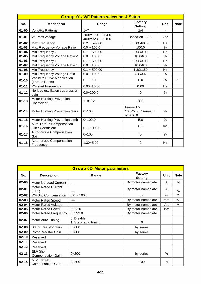
Group 01- V/F Pattern selection & Setup No. Description Range Factory
Setting Unit Note
01-00 Volts/Hz Patterns 1~7 1/4 -
01-01 V/F Max voltage 200V:170.0~264.0 400V:323.0~528.0 Based on 13-08 Vac
01-02 Max Frequency 0.2 ~ 599.00 50.00/60.00 Hz 01-03 Max Frequency Voltage Ratio 0.0 ~ 100.0 100.0 % 01-04 Mid Frequency 2 0.1 ~ 599.00 2.50/3.00 Hz 01-05 Mid Frequency Voltage Ratio 2 0.0 ~ 100.0 10.0/6.8 % 01-06 Mid Frequency 1 0.1 ~ 599.00 2.50/3.00 Hz 01-07 Mid Frequency Voltage Ratio 1 0.0 ~ 100.0 10.0/6.8 % 01-08 Min Frequency 0.1 ~ 599.00 1.30/1.50 Hz 01-09 Min Frequency Voltage Ratio 0.0 ~ 100.0 8.0/3.4 %
01-10 Volts/Hz Curve Modification (Torque Boost) 0 ~ 10.0 0.0 % *1
01-11 V/F start Frequency 0.00~10.00 0.00 Hz
01-12 No-load oscillation suppression gain 0.0~200.0 0 %
01-13 Motor Hunting Prevention Coefficient 1~8192 800
01-14 Motor Hunting Prevention Gain 0~100 Frame 1/2 100V/200V series: 7 others: 0
%
01-15 Motor Hunting Prevention Limit 0~100.0 5.0 %
01-16 Auto-Torque Compensation Filter Coefficient 0.1~1000.0 0.1 ms
01-17 Auto-torque Compensation Gain 0~100 0 %
01-18 Auto-torque Compensation Frequency 1.30~5.00 2 Hz
Group 02- Motor parameters No. Description Range Factory
Setting Unit Note
02-00 Motor No Load Current ---- By motor nameplate A *4
02-01 Motor Rated Current (OL1) ---- By motor nameplate A *4
02-02 V/F Slip Compensation 0.0 ~ 100.0 0.0 % *1 02-03 Motor Rated Speed ---- By motor nameplate rpm *4 02-04 Motor Rated Voltage ---- By motor nameplate Vac *4 02-05 Motor Rated Power 0~22.0 By motor nameplate kW 02-06 Motor Rated Frequency 0~599.0 By motor nameplate
02-07 Motor Auto Tuning 0: Disable 1: Static auto tuning 0
02-08 Stator Resistor Gain 0~600 by series 02-09 Rotor Resistor Gain 0~600 by series 02-10 Reserved 02-11 Reserved 02-12 Reserved
02-13 SLV Slip Compensation Gain 0~200 by series %
02-14 SLV Torque Compensation Gain 0~200 100 %
4-12
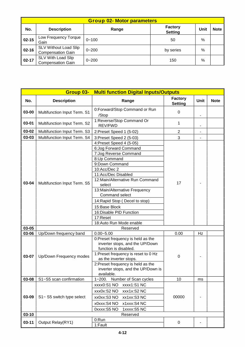
Group 02- Motor parameters No. Description Range Factory
Setting Unit Note
02-15 Low Frequency Torque Gain 0~100 50 %
02-16 SLV Without Load Slip Compensation Gain 0~200 by series %
02-17 SLV With Load Slip Compensation Gain 0~200 150 %
Group 03- Multi function Digital Inputs/Outputs No. Description Range Factory
Setting Unit Note
03-00 Multifunction Input Term. S1 0:Forward/Stop Command or Run
/Stop 0
-
03-01 Multifunction Input Term. S2 1:Reverse/Stop Command Or REV/FWD 1 -
03-02 Multifunction Input Term. S3 2:Preset Speed 1 (5-02) 2 - 03-03 Multifunction Input Term. S4 3:Preset Speed 2 (5-03) 3 -
03-04 Multifunction Input Term. S5
4:Preset Speed 4 (5-05)
17 -
6:Jog Forward Command 7:Jog Reverse Command 8:Up Command 9:Down Command 10:Acc/Dec 2 11:Acc/Dec Disabled 12:Main/Alternative Run Command
select 13:Main/Alternative Frequency
Command select 14:Rapid Stop ( Decel to stop) 15:Base Block 16:Disable PID Function 17:Reset 18:Auto Run Mode enable
03-05 Reserved 03-06 Up/Down frequency band 0.00~5.00 0.00 Hz
03-07 Up/Down Frequency modes
0:Preset frequency is held as the inverter stops, and the UP/Down function is disabled.
0 -
1:Preset frequency is reset to 0 Hz as the inverter stops.
2:Preset frequency is held as the inverter stops, and the UP/Down is available.
03-08 S1~S5 scan confirmation 1~200. Number of Scan cycles 10 ms
03-09 S1~ S5 switch type select
xxxx0:S1 NO xxxx1:S1 NC
00000 -
xxx0x:S2 NO xxx1x:S2 NC xx0xx:S3 NO xx1xx:S3 NC x0xxx:S4 NO x1xxx:S4 NC 0xxxx:S5 NO 1xxxx:S5 NC
03-10 Reserved
03-11 Output Relay(RY1) 0:Run 0 - 1:Fault
4-13
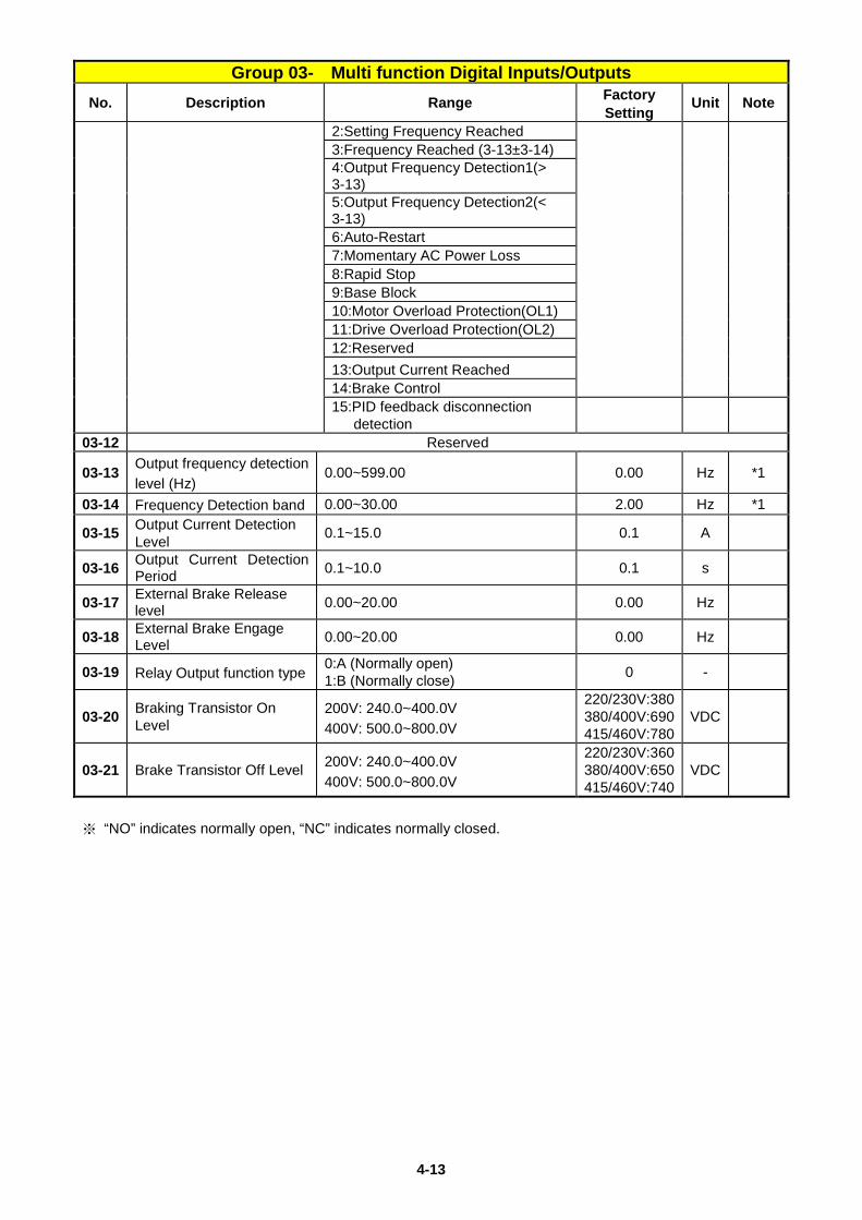
Group 03- Multi function Digital Inputs/Outputs No. Description Range Factory
Setting Unit Note
2:Setting Frequency Reached 3:Frequency Reached (3-13±3-14) 4:Output Frequency Detection1(> 3-13) 5:Output Frequency Detection2(< 3-13) 6:Auto-Restart 7:Momentary AC Power Loss 8:Rapid Stop 9:Base Block 10:Motor Overload Protection(OL1) 11:Drive Overload Protection(OL2) 12:Reserved 13:Output Current Reached 14:Brake Control 15:PID feedback disconnection
detection
03-12 Reserved
03-13 Output frequency detection level (Hz)
0.00~599.00 0.00 Hz *1
03-14 Frequency Detection band 0.00~30.00 2.00 Hz *1
03-15 Output Current Detection Level 0.1~15.0 0.1 A
03-16 Output Current Detection Period 0.1~10.0 0.1 s
03-17 External Brake Release level 0.00~20.00 0.00 Hz
03-18 External Brake Engage Level 0.00~20.00 0.00 Hz
03-19 Relay Output function type 0:A (Normally open) 1:B (Normally close) 0 -
03-20 Braking Transistor On Level
200V: 240.0~400.0V 400V: 500.0~800.0V
220/230V:380 380/400V:690 415/460V:780
VDC
03-21 Brake Transistor Off Level 200V: 240.0~400.0V 400V: 500.0~800.0V
220/230V:360 380/400V:650 415/460V:740
VDC
※ “NO” indicates normally open, “NC” indicates normally closed.
4-14
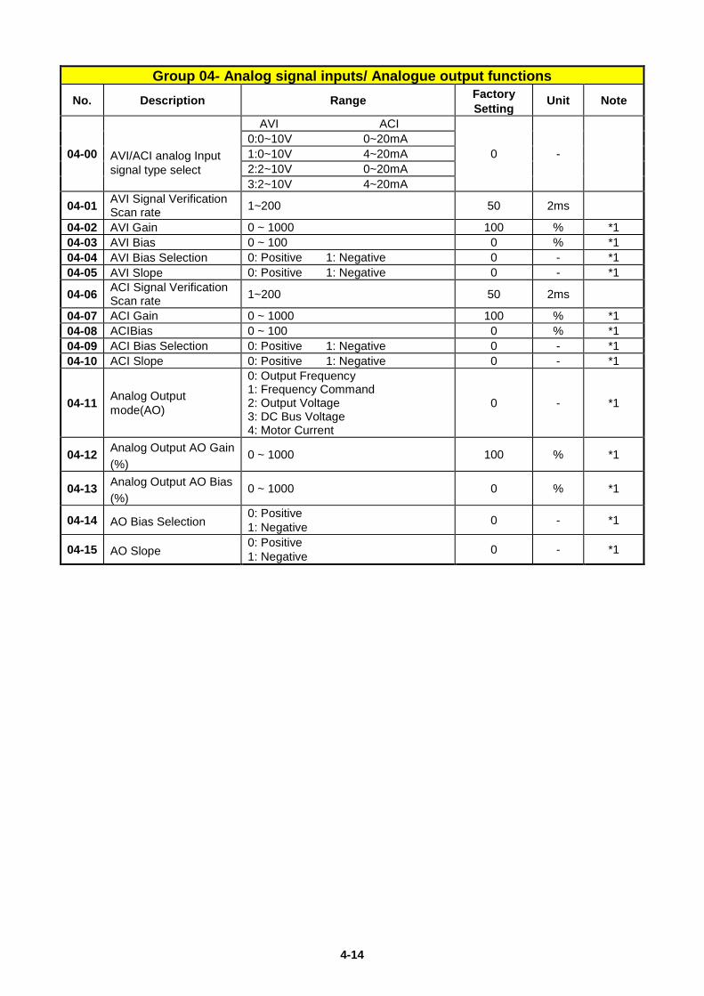
Group 04- Analog signal inputs/ Analogue output functions
No. Description Range Factory Setting
Unit Note
04-00 AVI/ACI analog Input signal type select
AVI ACI
0 - 0:0~10V 0~20mA 1:0~10V 4~20mA 2:2~10V 0~20mA 3:2~10V 4~20mA
04-01 AVI Signal Verification Scan rate 1~200 50 2ms
04-02 AVI Gain 0 ~ 1000 100 % *1 04-03 AVI Bias 0 ~ 100 0 % *1 04-04 AVI Bias Selection 0: Positive 1: Negative 0 - *1 04-05 AVI Slope 0: Positive 1: Negative 0 - *1
04-06 ACI Signal Verification Scan rate 1~200 50 2ms
04-07 ACI Gain 0 ~ 1000 100 % *1 04-08 ACIBias 0 ~ 100 0 % *1 04-09 ACI Bias Selection 0: Positive 1: Negative 0 - *1 04-10 ACI Slope 0: Positive 1: Negative 0 - *1
04-11 Analog Output mode(AO)
0: Output Frequency 1: Frequency Command 2: Output Voltage 3: DC Bus Voltage 4: Motor Current
0 - *1
04-12 Analog Output AO Gain (%)
0 ~ 1000 100 % *1
04-13 Analog Output AO Bias (%)
0 ~ 1000 0 % *1
04-14 AO Bias Selection 0: Positive 1: Negative 0 - *1
04-15 AO Slope 0: Positive 1: Negative 0 - *1
4-15
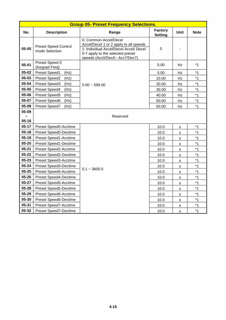
Group 05- Preset Frequency Selections.
No. Description Range Factory Setting
Unit Note
05-00 Preset Speed Control mode Selection
0: Common Accel/Decel Accel/Decel 1 or 2 apply to all speeds
0 - 1: Individual Accel/Decel Accel/ Decel 0-7 apply to the selected preset speeds (Acc0/Dec0~ Acc7/Dec7)
05-01 Preset Speed 0 (Keypad Freq)
0.00 ~ 599.00
5.00 Hz *1
05-02 Preset Speed1 (Hz) 5.00 Hz *1 05-03 Preset Speed2 (Hz) 10.00 Hz *1 05-04 Preset Speed3 (Hz) 20.00 Hz *1 05-05 Preset Speed4 (Hz) 30.00 Hz *1 05-06 Preset Speed5 (Hz) 40.00 Hz *1 05-07 Preset Speed6 (Hz) 50.00 Hz *1 05-08 Preset Speed7 (Hz) 50.00 Hz *1 05-09
~ 05-16
Reserved
05-17 Preset Speed0-Acctime
0.1 ~ 3600.0
10.0 s *1 05-18 Preset Speed0-Dectime 10.0 s *1 05-19 Preset Speed1-Acctime 10.0 s *1 05-20 Preset Speed1-Dectime 10.0 s *1 05-21 Preset Speed2-Acctime 10.0 s *1 05-22 Preset Speed2-Dectime 10.0 s *1 05-23 Preset Speed3-Acctime 10.0 s *1 05-24 Preset Speed3-Dectime 10.0 s *1 05-25 Preset Speed4-Acctime 10.0 s *1 05-26 Preset Speed4-Dectime 10.0 s *1 05-27 Preset Speed5-Acctime 10.0 s *1 05-28 Preset Speed5-Dectime 10.0 s *1 05-29 Preset Speed6-Acctime 10.0 s *1 05-30 Preset Speed6-Dectime 10.0 s *1 05-31 Preset Speed7-Acctime 10.0 s *1 05-32 Preset Speed7-Dectime 10.0 s *1
4-16
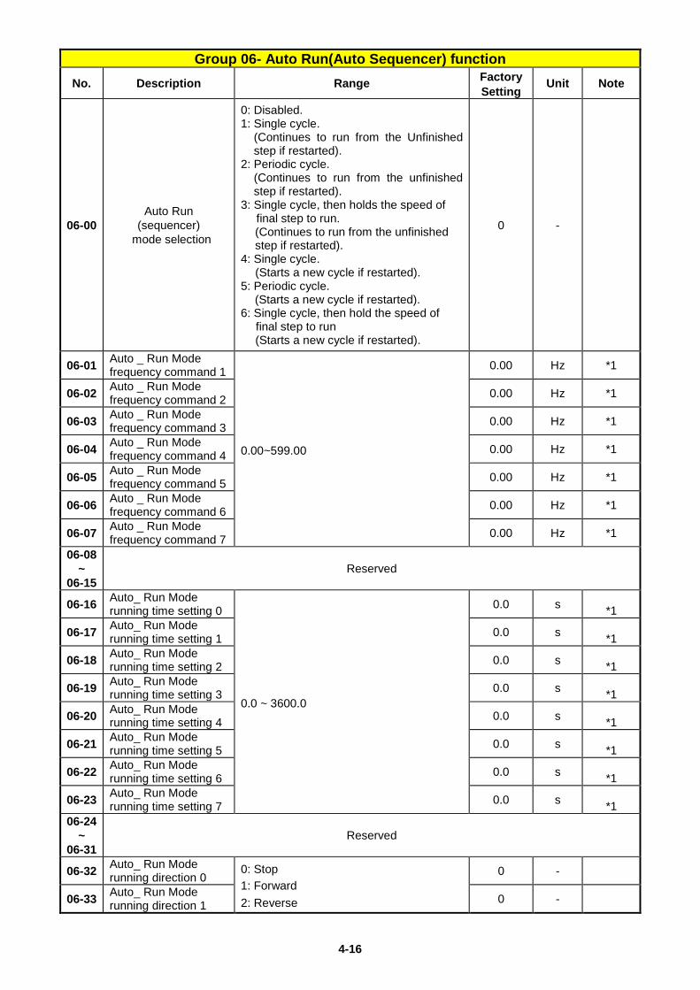
Group 06- Auto Run(Auto Sequencer) function No. Description Range Factory
Setting Unit Note
06-00 Auto Run
(sequencer) mode selection
0: Disabled. 1: Single cycle.
(Continues to run from the Unfinished step if restarted).
2: Periodic cycle. (Continues to run from the unfinished step if restarted).
3: Single cycle, then holds the speed of final step to run. (Continues to run from the unfinished step if restarted).
4: Single cycle. (Starts a new cycle if restarted).
5: Periodic cycle. (Starts a new cycle if restarted).
6: Single cycle, then hold the speed of final step to run (Starts a new cycle if restarted).
0 -
06-01 Auto _ Run Mode frequency command 1
0.00~599.00
0.00 Hz *1
06-02 Auto _ Run Mode frequency command 2 0.00 Hz *1
06-03 Auto _ Run Mode frequency command 3 0.00 Hz *1
06-04 Auto _ Run Mode frequency command 4 0.00 Hz *1
06-05 Auto _ Run Mode frequency command 5 0.00 Hz *1
06-06 Auto _ Run Mode frequency command 6 0.00 Hz *1
06-07 Auto _ Run Mode frequency command 7 0.00 Hz *1
06-08 ~
06-15 Reserved
06-16 Auto_ Run Mode running time setting 0
0.0 ~ 3600.0
0.0 s *1
06-17 Auto_ Run Mode running time setting 1 0.0 s *1
06-18 Auto_ Run Mode running time setting 2 0.0 s *1
06-19 Auto_ Run Mode running time setting 3 0.0 s *1
06-20 Auto_ Run Mode running time setting 4 0.0 s *1
06-21 Auto_ Run Mode running time setting 5 0.0 s *1
06-22 Auto_ Run Mode running time setting 6 0.0 s *1
06-23 Auto_ Run Mode running time setting 7 0.0 s *1
06-24 ~
06-31 Reserved
06-32 Auto_ Run Mode running direction 0
0: Stop 1: Forward 2: Reverse
0 -
06-33 Auto_ Run Mode running direction 1 0 -
4-17
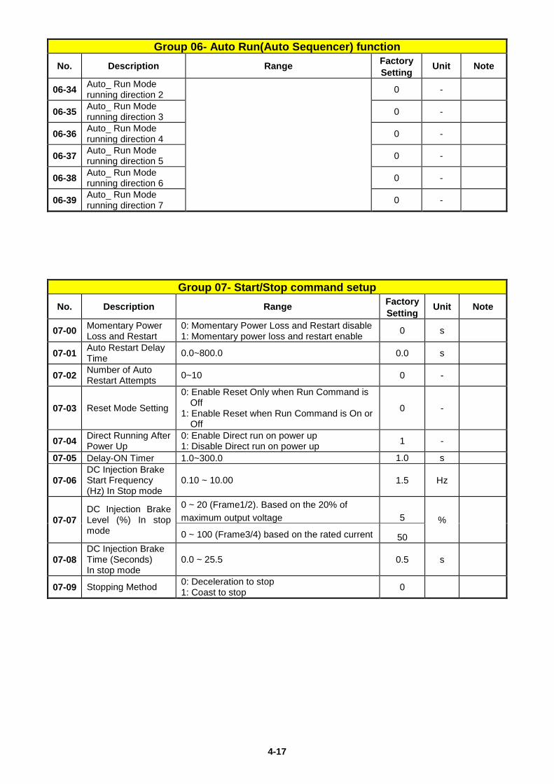
Group 06- Auto Run(Auto Sequencer) function No. Description Range Factory
Setting Unit Note
06-34 Auto_ Run Mode running direction 2 0 -
06-35 Auto_ Run Mode running direction 3 0 -
06-36 Auto_ Run Mode running direction 4 0 -
06-37 Auto_ Run Mode running direction 5 0 -
06-38 Auto_ Run Mode running direction 6 0 -
06-39 Auto_ Run Mode running direction 7 0 -
Group 07- Start/Stop command setup No. Description Range Factory
Setting Unit Note
07-00 Momentary Power Loss and Restart
0: Momentary Power Loss and Restart disable 1: Momentary power loss and restart enable 0 s
07-01 Auto Restart Delay Time 0.0~800.0 0.0 s
07-02 Number of Auto Restart Attempts 0~10 0 -
07-03 Reset Mode Setting
0: Enable Reset Only when Run Command is Off
1: Enable Reset when Run Command is On or Off
0 -
07-04 Direct Running After Power Up
0: Enable Direct run on power up 1: Disable Direct run on power up 1 -
07-05 Delay-ON Timer 1.0~300.0 1.0 s
07-06 DC Injection Brake Start Frequency (Hz) In Stop mode
0.10 ~ 10.00 1.5 Hz
07-07 DC Injection Brake Level (%) In stop mode
0 ~ 20 (Frame1/2). Based on the 20% of maximum output voltage 5 % 0 ~ 100 (Frame3/4) based on the rated current 50
07-08 DC Injection Brake Time (Seconds) In stop mode
0.0 ~ 25.5 0.5 s
07-09 Stopping Method 0: Deceleration to stop 1: Coast to stop 0
4-18
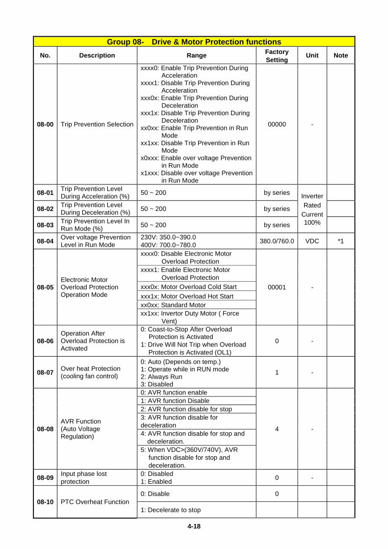
Group 08- Drive & Motor Protection functions No. Description Range Factory
Setting Unit Note
08-00 Trip Prevention Selection
xxxx0: Enable Trip Prevention During Acceleration
xxxx1: Disable Trip Prevention During Acceleration
xxx0x: Enable Trip Prevention During Deceleration
xxx1x: Disable Trip Prevention During Deceleration
xx0xx: Enable Trip Prevention in Run Mode
xx1xx: Disable Trip Prevention in Run Mode
x0xxx: Enable over voltage Prevention in Run Mode
x1xxx: Disable over voltage Prevention in Run Mode
00000 -
08-01 Trip Prevention Level During Acceleration (%) 50 ~ 200 by series Inverter
Rated Current 100%
08-02 Trip Prevention Level During Deceleration (%) 50 ~ 200 by series
08-03 Trip Prevention Level In Run Mode (%) 50 ~ 200 by series
08-04 Over voltage Prevention Level in Run Mode
230V: 350.0~390.0 400V: 700.0~780.0 380.0/760.0 VDC *1
08-05 Electronic Motor Overload Protection Operation Mode
xxxx0: Disable Electronic Motor Overload Protection
00001 -
xxxx1: Enable Electronic Motor Overload Protection
xxx0x: Motor Overload Cold Start xxx1x: Motor Overload Hot Start xx0xx: Standard Motor xx1xx: Invertor Duty Motor ( Force
Vent)
08-06 Operation After Overload Protection is Activated
0: Coast-to-Stop After Overload Protection is Activated
1: Drive Will Not Trip when Overload Protection is Activated (OL1)
0 -
08-07 Over heat Protection (cooling fan control)
0: Auto (Depends on temp.) 1: Operate while in RUN mode 2: Always Run 3: Disabled
1 -
08-08 AVR Function (Auto Voltage Regulation)
0: AVR function enable
4 -
1: AVR function Disable 2: AVR function disable for stop 3: AVR function disable for deceleration 4: AVR function disable for stop and deceleration. 5: When VDC>(360V/740V), AVR
function disable for stop and deceleration.
08-09 Input phase lost protection
0: Disabled 1: Enabled 0 -
08-10 PTC Overheat Function 0: Disable 0
1: Decelerate to stop
4-19
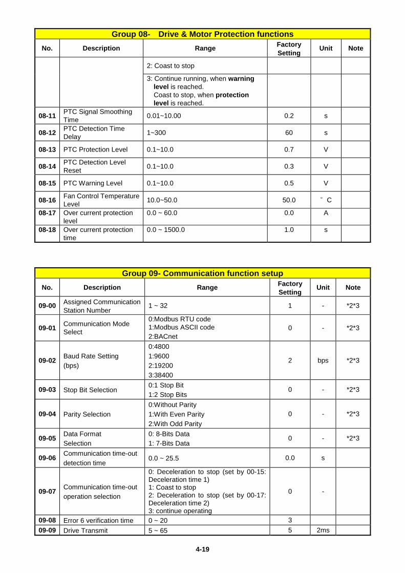
Group 08- Drive & Motor Protection functions No. Description Range Factory
Setting Unit Note
2: Coast to stop
3: Continue running, when warning level is reached.
Coast to stop, when protection level is reached.
08-11 PTC Signal Smoothing Time 0.01~10.00 0.2 s
08-12 PTC Detection Time Delay 1~300 60 s
08-13 PTC Protection Level 0.1~10.0 0.7 V
08-14 PTC Detection Level Reset 0.1~10.0 0.3 V
08-15 PTC Warning Level 0.1~10.0 0.5 V
08-16 Fan Control Temperature Level 10.0~50.0 50.0 °C
08-17 Over current protection level
0.0 ~ 60.0 0.0 A
08-18 Over current protection time
0.0 ~ 1500.0 1.0 s
Group 09- Communication function setup No. Description Range Factory
Setting Unit Note
09-00 Assigned Communication Station Number
1 ~ 32 1 - *2*3
09-01 Communication Mode Select
0:Modbus RTU code 1:Modbus ASCII code 2:BACnet
0 - *2*3
09-02 Baud Rate Setting (bps)
0:4800 1:9600 2:19200 3:38400
2 bps *2*3
09-03 Stop Bit Selection 0:1 Stop Bit 1:2 Stop Bits
0 - *2*3
09-04 Parity Selection 0:Without Parity 1:With Even Parity 2:With Odd Parity
0 - *2*3
09-05 Data Format Selection
0: 8-Bits Data 1: 7-Bits Data
0 - *2*3
09-06 Communication time-out detection time
0.0 ~ 25.5 0.0 s
09-07 Communication time-out operation selection
0: Deceleration to stop (set by 00-15: Deceleration time 1) 1: Coast to stop 2: Deceleration to stop (set by 00-17: Deceleration time 2) 3: continue operating
0 -
09-08 Error 6 verification time 0 ~ 20 3 09-09 Drive Transmit 5 ~ 65 5 2ms
4-20
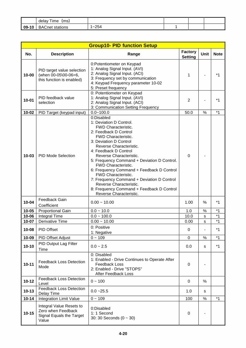
delay Time(ms) 09-10 BACnet stations 1~254 1
Group10- PID function Setup No. Description Range Factory
Setting Unit Note
10-00 PID target value selection (when 00-05\00-06=6, this function is enabled)
0:Potentiometer on Keypad 1: Analog Signal Input. (AVI) 2: Analog Signal Input. (ACI) 3: Frequency set by communication 4: Keypad Frequency parameter 10-02 5: Preset frequency
1 - *1
10-01 PID feedback value selection
0: Potentiometer on Keypad 1: Analog Signal Input. (AVI) 2: Analog Signal Input. (ACI) 3: Communication Setting Frequency
2 - *1
10-02 PID Target (keypad input) 0.0~100.0 50.0 % *1
10-03 PID Mode Selection
0:Disabled 1: Deviation D Control.
FWD Characteristic. 2: Feedback D Control
FWD Characteristic. 3: Deviation D Control
Reverse Characteristic. 4: Feedback D Control
Reverse Characteristic. 5: Frequency Command + Deviation D Control.
FWD Characteristic. 6: Frequency Command + Feedback D Control
FWD Characteristic. 7: Frequency Command + Deviation D Control
Reverse Characteristic. 8: Frequency Command + Feedback D Control
Reverse Characteristic.
0 -
10-04 Feedback Gain Coefficient
0.00 ~ 10.00 1.00 % *1
10-05 Proportional Gain 0.0 ~ 10.0 1.0 % *1 10-06 Integral Time 0.0 ~ 100.0 10.0 s *1 10-07 Derivative Time 0.00 ~ 10.00 0.00 s *1
10-08 PID Offset 0: Positive 1: Negative
0 - *1
10-09 PID Offset Adjust 0 ~ 109 0 % *1
10-10 PID Output Lag Filter Time
0.0 ~ 2.5 0.0 s *1
10-11 Feedback Loss Detection Mode
0: Disabled 1: Enabled - Drive Continues to Operate After
Feedback Loss 2: Enabled - Drive "STOPS"
After Feedback Loss
0 -
10-12 Feedback Loss Detection Level 0 ~ 100 0 %
10-13 Feedback Loss Detection Delay Time 0.0 ~25.5 1.0 s
10-14 Integration Limit Value 0 ~ 109 100 % *1
10-15
Integral Value Resets to Zero when Feedback Signal Equals the Target Value
0:Disabled 1: 1 Second 30: 30 Seconds (0 ~ 30)
0 -
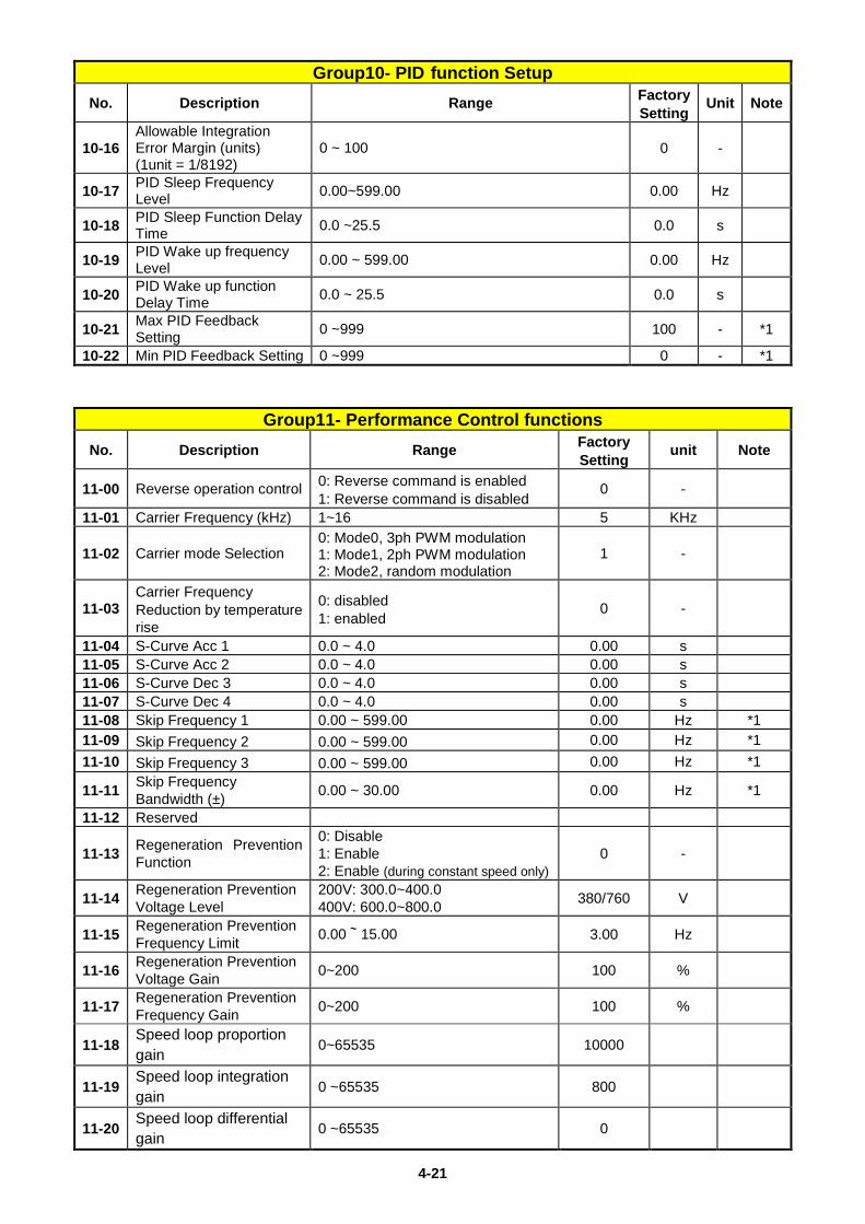
4-21
Group10- PID function Setup No. Description Range Factory
Setting Unit Note
10-16 Allowable Integration Error Margin (units) (1unit = 1/8192)
0 ~ 100 0 -
10-17 PID Sleep Frequency Level 0.00~599.00 0.00 Hz
10-18 PID Sleep Function Delay Time 0.0 ~25.5 0.0 s
10-19 PID Wake up frequency Level 0.00 ~ 599.00 0.00 Hz
10-20 PID Wake up function Delay Time 0.0 ~ 25.5 0.0 s
10-21 Max PID Feedback Setting 0 ~999 100 - *1
10-22 Min PID Feedback Setting 0 ~999 0 - *1
Group11- Performance Control functions No. Description Range Factory
Setting unit Note
11-00 Reverse operation control 0: Reverse command is enabled 1: Reverse command is disabled
0 -
11-01 Carrier Frequency (kHz) 1~16 5 KHz
11-02 Carrier mode Selection 0: Mode0, 3ph PWM modulation 1: Mode1, 2ph PWM modulation 2: Mode2, random modulation
1 -
11-03 Carrier Frequency Reduction by temperature rise
0: disabled 1: enabled
0 -
11-04 S-Curve Acc 1 0.0 ~ 4.0 0.00 s 11-05 S-Curve Acc 2 0.0 ~ 4.0 0.00 s 11-06 S-Curve Dec 3 0.0 ~ 4.0 0.00 s 11-07 S-Curve Dec 4 0.0 ~ 4.0 0.00 s 11-08 Skip Frequency 1 0.00 ~ 599.00 0.00 Hz *1 11-09 Skip Frequency 2 0.00 ~ 599.00 0.00 Hz *1 11-10 Skip Frequency 3 0.00 ~ 599.00 0.00 Hz *1
11-11 Skip Frequency Bandwidth (±) 0.00 ~ 30.00 0.00 Hz *1
11-12 Reserved
11-13 Regeneration Prevention Function
0: Disable 1: Enable 2: Enable (during constant speed only)
0 -
11-14 Regeneration Prevention Voltage Level
200V: 300.0~400.0 400V: 600.0~800.0 380/760 V
11-15 Regeneration Prevention Frequency Limit 0.00~15.00 3.00 Hz
11-16 Regeneration Prevention Voltage Gain 0~200 100 %
11-17 Regeneration Prevention Frequency Gain 0~200 100 %
11-18 Speed loop proportion gain
0~65535 10000
11-19 Speed loop integration gain
0 ~65535 800
11-20 Speed loop differential gain
0 ~65535 0
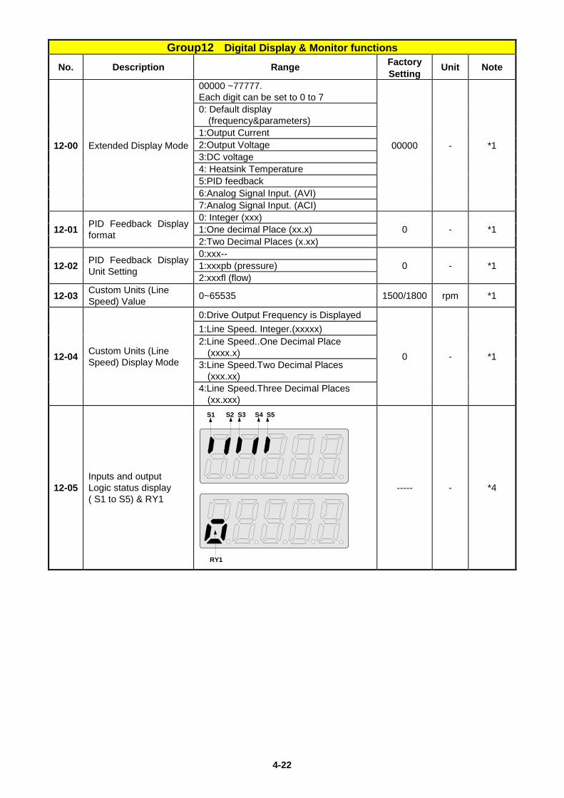
4-22
Group12 Digital Display & Monitor functions No. Description Range Factory
Setting Unit Note
12-00 Extended Display Mode
00000 ~77777. Each digit can be set to 0 to 7
00000 - *1
0: Default display (frequency¶meters)
1:Output Current 2:Output Voltage 3:DC voltage 4: Heatsink Temperature 5:PID feedback 6:Analog Signal Input. (AVI) 7:Analog Signal Input. (ACI)
12-01 PID Feedback Display format
0: Integer (xxx) 0 - *1 1:One decimal Place (xx.x)
2:Two Decimal Places (x.xx)
12-02 PID Feedback Display Unit Setting
0:xxx-- 0 - *1 1:xxxpb (pressure)
2:xxxfl (flow)
12-03 Custom Units (Line Speed) Value 0~65535 1500/1800 rpm *1
12-04 Custom Units (Line Speed) Display Mode
0:Drive Output Frequency is Displayed
0 - *1
1:Line Speed. Integer.(xxxxx) 2:Line Speed..One Decimal Place
(xxxx.x) 3:Line Speed.Two Decimal Places
(xxx.xx) 4:Line Speed.Three Decimal Places
(xx.xxx)
12-05 Inputs and output Logic status display ( S1 to S5) & RY1
S1 S2 S3 S4 S5
RY1
----- - *4
4-23
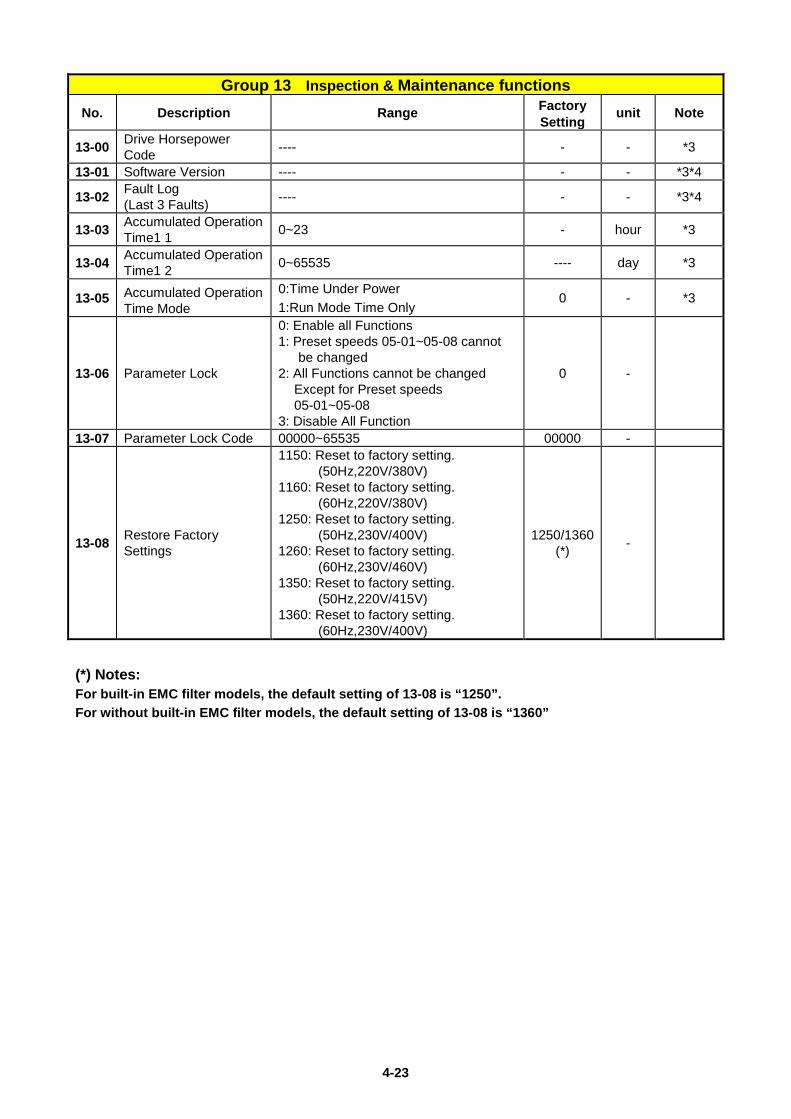
Group 13 Inspection & Maintenance functions
No. Description Range Factory Setting
unit Note
13-00 Drive Horsepower Code ---- - - *3
13-01 Software Version ---- - - *3*4
13-02 Fault Log (Last 3 Faults) ---- - - *3*4
13-03 Accumulated Operation Time1 1 0~23 - hour *3
13-04 Accumulated Operation Time1 2 0~65535 ---- day *3
13-05 Accumulated Operation Time Mode
0:Time Under Power 1:Run Mode Time Only
0 - *3
13-06 Parameter Lock
0: Enable all Functions 1: Preset speeds 05-01~05-08 cannot
be changed 2: All Functions cannot be changed
Except for Preset speeds 05-01~05-08
3: Disable All Function
0 -
13-07 Parameter Lock Code 00000~65535 00000 -
13-08 Restore Factory Settings
1150: Reset to factory setting. (50Hz,220V/380V)
1160: Reset to factory setting. (60Hz,220V/380V)
1250: Reset to factory setting. (50Hz,230V/400V)
1260: Reset to factory setting. (60Hz,230V/460V)
1350: Reset to factory setting. (50Hz,220V/415V)
1360: Reset to factory setting. (60Hz,230V/400V)
1250/1360 (*) -
(*) Notes: For built-in EMC filter models, the default setting of 13-08 is “1250”. For without built-in EMC filter models, the default setting of 13-08 is “1360”
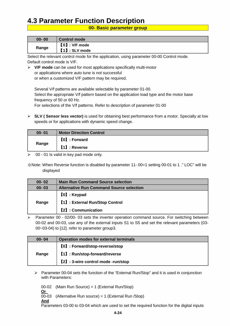
4-24
4.3 Parameter Function Description 00- Basic parameter group
00- 00 Control mode
Range 【0】: V/F mode 【1】: SLV mode
Select the relevant control mode for the application, using parameter 00-00 Control mode. Default control mode is V/F. V/F mode can be used for most applications specifically multi-motor
or applications where auto tune is not successful or when a customized V/F pattern may be required.
Several V/f patterns are available selectable by parameter 01-00. Select the appropriate V/f pattern based on the application load type and the motor base frequency of 50 or 60 Hz. For selections of the V/f patterns. Refer to description of parameter 01-00
SLV ( Sensor less vector) is used for obtaining best performance from a motor. Specially at low
speeds or for applications with dynamic speed change.
00- 01 Motor Direction Control
Range 【0】: Forward
【1】: Reverse
00 - 01 Is valid in key pad mode only.
※Note: When Reverse function is disabled by parameter 11- 00=1 setting 00-01 to 1 .” LOC” will be displayed
00- 02 Main Run Command Source selection 00- 03 Alternative Run Command Source selection
Range
【0】: Keypad
【1】: External Run/Stop Control
【2】: Communication
Parameter 00 - 02/00- 03 sets the inverter operation command source. For switching between 00-02 and 00-03, use any of the external inputs S1 to S5 and set the relevant parameters (03-00~03-04) to [12]. refer to parameter group3.
00- 04 Operation modes for external terminals
Range
【0】: Forward/stop-reverse/stop
【1】: Run/stop-forward/reverse
【2】: 3-wire control mode -run/stop Parameter 00-04 sets the function of the “External Run/Stop” and it is used in conjunction
with Parameters: 00-02 (Main Run Source) = 1 (External Run/Stop) Or 00-03 (Alternative Run source) = 1 (External Run /Stop) And Parameters 03-00 to 03-04 which are used to set the required function for the digital inputs
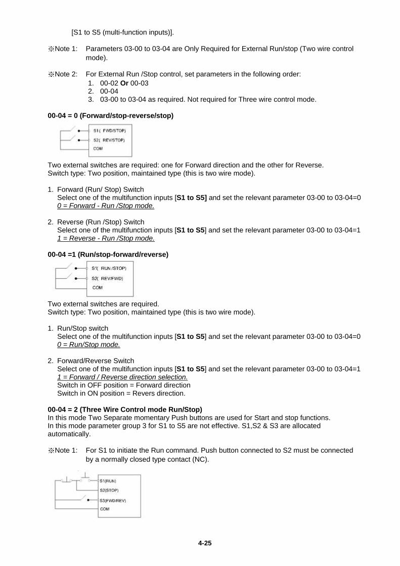
4-25
[S1 to S5 (multi-function inputs)]. ※Note 1: Parameters 03-00 to 03-04 are Only Required for External Run/stop (Two wire control
mode). ※Note 2: For External Run /Stop control, set parameters in the following order:
1. 00-02 Or 00-03 2. 00-04 3. 03-00 to 03-04 as required. Not required for Three wire control mode.
00-04 = 0 (Forward/stop-reverse/stop)
Two external switches are required: one for Forward direction and the other for Reverse. Switch type: Two position, maintained type (this is two wire mode). 1. Forward (Run/ Stop) Switch Select one of the multifunction inputs [S1 to S5] and set the relevant parameter 03-00 to 03-04=0 0 = Forward - Run /Stop mode. 2. Reverse (Run /Stop) Switch Select one of the multifunction inputs [S1 to S5] and set the relevant parameter 03-00 to 03-04=1 1 = Reverse - Run /Stop mode. 00-04 =1 (Run/stop-forward/reverse)
Two external switches are required. Switch type: Two position, maintained type (this is two wire mode). 1. Run/Stop switch Select one of the multifunction inputs [S1 to S5] and set the relevant parameter 03-00 to 03-04=0 0 = Run/Stop mode. 2. Forward/Reverse Switch Select one of the multifunction inputs [S1 to S5] and set the relevant parameter 03-00 to 03-04=1 1 = Forward / Reverse direction selection. Switch in OFF position = Forward direction Switch in ON position = Revers direction. 00-04 = 2 (Three Wire Control mode Run/Stop) In this mode Two Separate momentary Push buttons are used for Start and stop functions. In this mode parameter group 3 for S1 to S5 are not effective. S1,S2 & S3 are allocated automatically. ※Note 1: For S1 to initiate the Run command. Push button connected to S2 must be connected
by a normally closed type contact (NC).
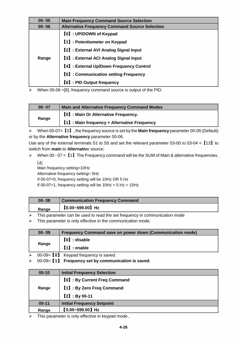
4-26
00- 05 Main Frequency Command Source Selection 00- 06 Alternative Frequency Command Source Selection
Range
【0】: UP/DOWN of Keypad
【1】: Potentiometer on Keypad
【2】: External AVI Analog Signal Input
【3】: External ACI Analog Signal Input
【4】: External Up/Down Frequency Control
【5】: Communication setting Frequency
【6】: PID Output frequency When 00-06 =[6], frequency command source is output of the PID.
00- 07 Main and Alternative Frequency Command Modes
Range 【0】: Main Or Alternative Frequency.
【1】: Main frequency + Alternative Frequency
When 00-07=【0】, the frequency source is set by the Main frequency parameter 00-05 (Default) or by the Alternative frequency parameter 00-06. Use any of the external terminals S1 to S5 and set the relevant parameter 03-00 to 03-04 =【13】to switch from main to Alternative source. When 00 - 07 =【1】The Frequency command will be the SUM of Main & alternative frequencies.
I.e: Main frequency setting=10Hz Alternative frequency setting= 5Hz If 00-07=0, frequency setting will be 10Hz OR 5 Hz If 00-07=1, frequency setting will be 10Hz + 5 Hz = 15Hz
00- 08 Communication Frequency Command
Range 【0.00~599.00】Hz This parameter can be used to read the set frequency in communication mode This parameter is only effective in the communication mode.
00- 09 Frequency Command save on power down (Communication mode)
Range 【0】: disable
【1】: enable
00-09=【0】 Keypad frequency is saved. 00-09=【1】 Frequency set by communication is saved.
00-10 Initial Frequency Selection
Range
【0】: By Current Freq Command
【1】: By Zero Freq Command
【2】: By 00-11 00-11 Initial Frequency Setpoint Range 【0.00~599.00】Hz
This parameter is only effective in keypad mode..
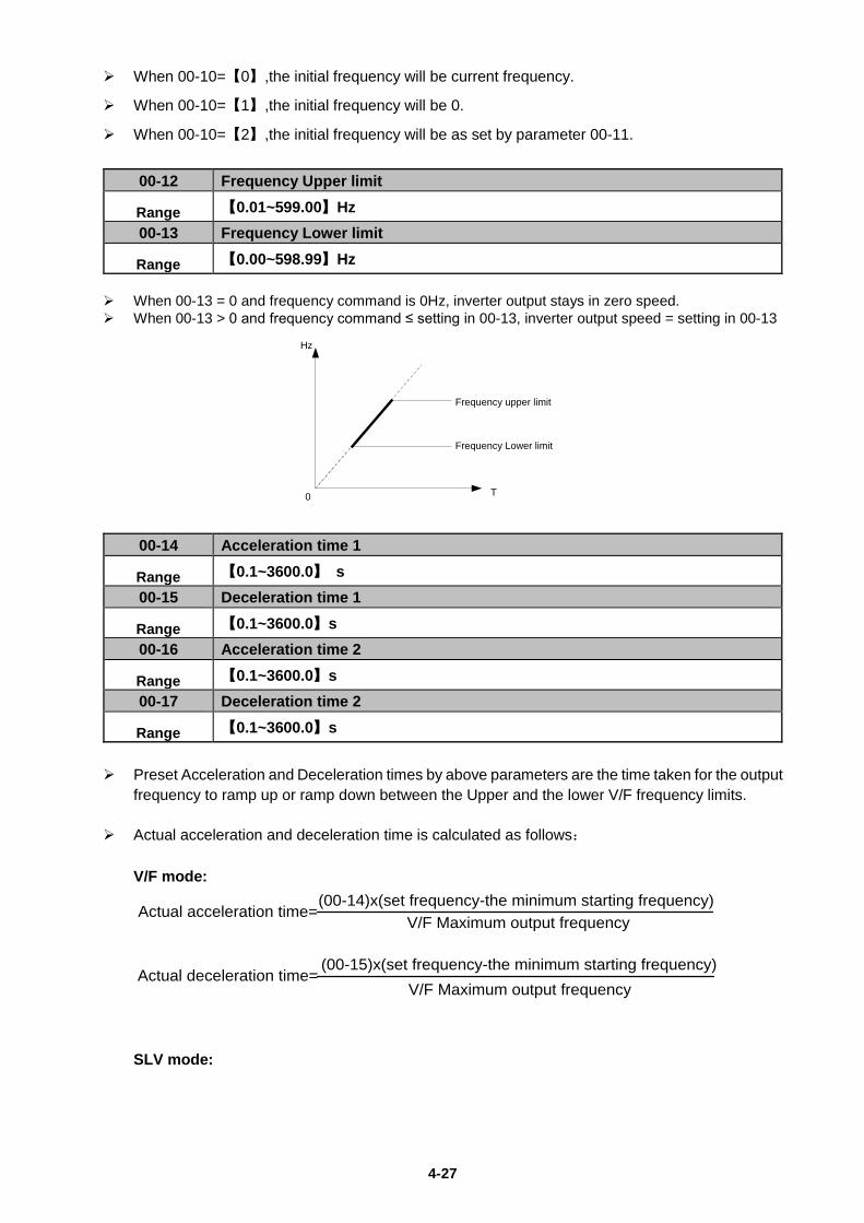
4-27
When 00-10=【0】,the initial frequency will be current frequency.
When 00-10=【1】,the initial frequency will be 0.
When 00-10=【2】,the initial frequency will be as set by parameter 00-11.
00-12 Frequency Upper limit
Range 【0.01~599.00】Hz 00-13 Frequency Lower limit
Range 【0.00~598.99】Hz When 00-13 = 0 and frequency command is 0Hz, inverter output stays in zero speed. When 00-13 > 0 and frequency command ≤ setting in 00-13, inverter output speed = setting in 00-13
Frequency upper limit
Frequency Lower limit
0
Hz
T
00-14 Acceleration time 1
Range 【0.1~3600.0】 s 00-15 Deceleration time 1
Range 【0.1~3600.0】s 00-16 Acceleration time 2
Range 【0.1~3600.0】s 00-17 Deceleration time 2
Range 【0.1~3600.0】s Preset Acceleration and Deceleration times by above parameters are the time taken for the output
frequency to ramp up or ramp down between the Upper and the lower V/F frequency limits.
Actual acceleration and deceleration time is calculated as follows:
V/F mode:
(00-15)x(set frequency-the minimum starting frequency)
Actual acceleration time=(00-14)x(set frequency-the minimum starting frequency)
V/F Maximum output frequency
Actual deceleration time=V/F Maximum output frequency
SLV mode:
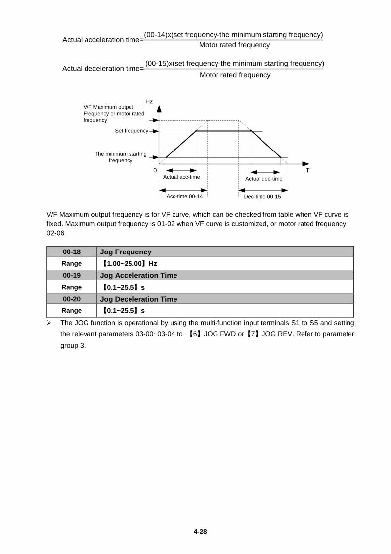
4-28
(00-15)x(set frequency-the minimum starting frequency)
Actual acceleration time=(00-14)x(set frequency-the minimum starting frequency)
Motor rated frequency
Actual deceleration time=Motor rated frequency
V/F Maximum output Frequency or motor rated frequency
Set frequency
Acc-time 00-14 Dec-time 00-15
Actual acc-time Actual dec-time
Hz
T0
The minimum starting frequency
V/F Maximum output frequency is for VF curve, which can be checked from table when VF curve is fixed. Maximum output frequency is 01-02 when VF curve is customized, or motor rated frequency 02-06
00-18 Jog Frequency Range 【1.00~25.00】Hz 00-19 Jog Acceleration Time Range 【0.1~25.5】s 00-20 Jog Deceleration Time Range 【0.1~25.5】s
The JOG function is operational by using the multi-function input terminals S1 to S5 and setting the relevant parameters 03-00~03-04 to 【6】JOG FWD or【7】JOG REV. Refer to parameter group 3.
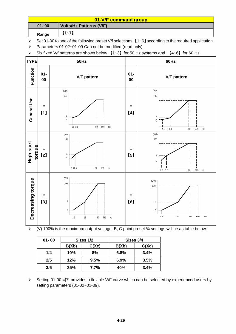
4-29
01-V/F command group 01- 00 Volts/Hz Patterns (V/F)
Range 【1~7】
Set 01-00 to one of the following preset V/f selections 【1~6】according to the required application. Parameters 01-02~01-09 Can not be modified (read only). Six fixed V/f patterns are shown below.【1~3】for 50 Hz systems and 【4~6】for 60 Hz.
TYPE 50Hz 60Hz
Func
tion
01-00 V/F pattern 01-
00 V/F pattern
Gen
eral
Use
=
【1】
100
BC
1.3 2.5 50
(V)%
Hz599
=【4】
Hig
h st
art
torq
ue
=【2】
100
BC
1.3 2.5 50
(V)%
Hz599
=【5】
Dec
reas
ing
torq
ue
=【3】
100
B
C
1.3 25 50
(V)%
Hz599
=【6】
(V) 100% is the maximum output voltage. B, C point preset % settings will be as table below:
01- 00 Sizes 1/2 Sizes 3/4 B(Xb) C(Xc) B(Xb) C(Xc)
1/4 10% 8% 6.8% 3.4%
2/5 12% 9.5% 6.9% 3.5%
3/6 25% 7.7% 40% 3.4% Setting 01-00 =[7] provides a flexible V/F curve which can be selected by experienced users by
setting parameters (01-02~01-09).
100
B
C
1.5 30 60
(V)%
Hz599
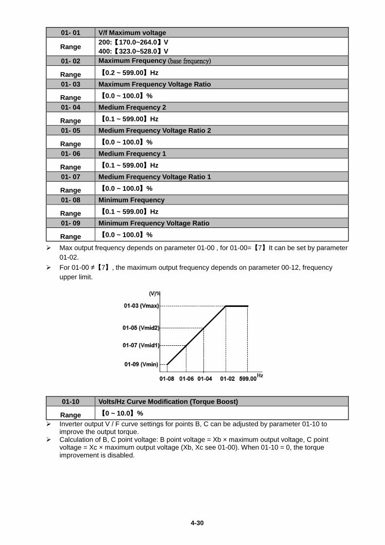
4-30
01- 01 V/f Maximum voltage
Range 200:【170.0~264.0】V 400:【323.0~528.0】V
01- 02 Maximum Frequency (base frequency)
Range 【0.2 ~ 599.00】Hz 01- 03 Maximum Frequency Voltage Ratio
Range 【0.0 ~ 100.0】% 01- 04 Medium Frequency 2
Range 【0.1 ~ 599.00】Hz 01- 05 Medium Frequency Voltage Ratio 2
Range 【0.0 ~ 100.0】% 01- 06 Medium Frequency 1
Range 【0.1 ~ 599.00】Hz 01- 07 Medium Frequency Voltage Ratio 1
Range 【0.0 ~ 100.0】% 01- 08 Minimum Frequency
Range 【0.1 ~ 599.00】Hz 01- 09 Minimum Frequency Voltage Ratio
Range 【0.0 ~ 100.0】%
Max output frequency depends on parameter 01-00 , for 01-00=【7】It can be set by parameter 01-02.
For 01-00 ≠【7】, the maximum output frequency depends on parameter 00-12, frequency upper limit.
01-10 Volts/Hz Curve Modification (Torque Boost)
Range 【0 ~ 10.0】% Inverter output V / F curve settings for points B, C can be adjusted by parameter 01-10 to
improve the output torque. Calculation of B, C point voltage: B point voltage = Xb × maximum output voltage, C point
voltage = Xc × maximum output voltage (Xb, Xc see 01-00). When 01-10 = 0, the torque improvement is disabled.
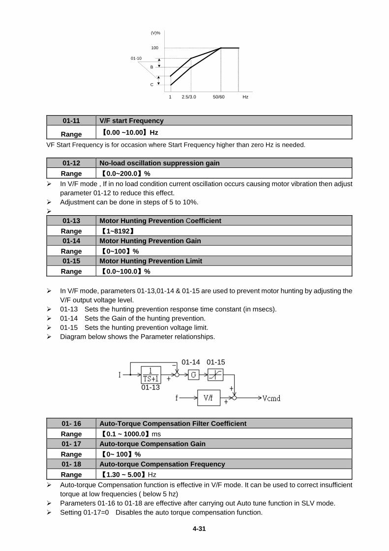
4-31
100
B
C
1 2.5/3.0 50/60
(V)%
Hz
01-10
01-11 V/F start Frequency
Range 【0.00 ~10.00】Hz
VF Start Frequency is for occasion where Start Frequency higher than zero Hz is needed.
01-12 No-load oscillation suppression gain Range 【0.0~200.0】%
In V/F mode , If in no load condition current oscillation occurs causing motor vibration then adjust parameter 01-12 to reduce this effect.
Adjustment can be done in steps of 5 to 10%.
01-13 Motor Hunting Prevention Coefficient Range 【1~8192】 01-14 Motor Hunting Prevention Gain Range 【0~100】% 01-15 Motor Hunting Prevention Limit Range 【0.0~100.0】%
In V/F mode, parameters 01-13,01-14 & 01-15 are used to prevent motor hunting by adjusting the
V/F output voltage level. 01-13 Sets the hunting prevention response time constant (in msecs). 01-14 Sets the Gain of the hunting prevention. 01-15 Sets the hunting prevention voltage limit. Diagram below shows the Parameter relationships.
01- 16 Auto-Torque Compensation Filter Coefficient Range 【0.1 ~ 1000.0】ms 01- 17 Auto-torque Compensation Gain Range 【0~ 100】% 01- 18 Auto-torque Compensation Frequency Range 【1.30 ~ 5.00】Hz
Auto-torque Compensation function is effective in V/F mode. It can be used to correct insufficient torque at low frequencies ( below 5 hz)
Parameters 01-16 to 01-18 are effective after carrying out Auto tune function in SLV mode. Setting 01-17=0 Disables the auto torque compensation function.
01-13
01-14 01-15
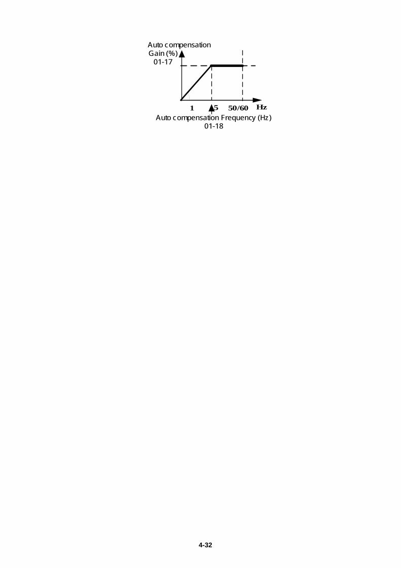
4-32
1 5 50/60
Auto compensationGain (%)
01-17
HzAuto compensation Frequency (Hz)
01-18
4-33
02- Motor parameter group
02- 00 Motor no load current. (For slip compensation calculation) Range ---- 02- 01 Motor Rated Current
※Note: Please set the value according to motor’s nameplate.
Range ---- 02- 02 Slip Compensation Gain. (V/f mode only)
Range 【0.0 ~ 100.0】(%) When the load causes the actual motor speed to be reduced below the speed set by
inverter output frequency (Slip) , parameter 02-02 Slip compensation can be used to correct the speed. Slip compensation calculation in V/F mode:
Slip compensation boost=Output Current-(02-00)
(02-01)-(02-00)x(02-02)xRate motor slip
Motor slip = Motor synchronous speed- Motor Rated Speed
(02-02)approximate Value=Motor synchronization speed-Rated speed
Motor synchronization speed 1204
Example: 4 poles, 60Hz induction motor synchronization speed= x 60=1800(RPM)
※Note: Parameters 02- 00/02- 01 have to be set according to the specific motor data and in relation to the Inverter rating model parameter (13- 00).
02- 03 Motor Rated Speed Range ----
Slide compensation limit, inverter will calculate the motor slide according to 02-03. V/F slide
compensation will not be higher than 02-03. ※Note: Please set the value according to motor’s nameplate.
02- 04 Motor Rated Voltage Range ----
In order to prevent the output voltage of inverter is too high. The output voltage value will not
be higher than 02-04. 02-04 can be changed during operation. ※Note: Please set the value according to motor’s nameplate.
4-34
02- 05 Motor Rated Power Range 【0~22.0】kW 02- 06 Motor Rated Frequency Range 【0~599.0】Hz
02- 07 Motor Auto Tuning
Range 【0】: Disable 【1】: Static auto tuning
02- 08 Stator Resistor Gain Range ---- 02- 09 Rotor Resistor Gain Range ----
Auto tune function in SLV mode. 00-00=【1】 Set motor parameters 02-01 and 02-03~02-06,then set 02-07 to【1 ] to start the auto tune
function. During the Auto tune function the display will show AT and show END briefly when auto tune is
completed then the display will return to the frequency display.
Following an auto tune the motor test data are stored in parameters 02-08&02-09 then the setting in 02-07 will automatically reset to 0. Notes: Carry out Auto tune again whenever replacing the motor. Auto tune function is not possible for applications with multi-motor connected to one inverter. Auto tune can be used on motors of equivalent size to the inverter or one size smaller(or one
size bigger). Just need to set the motor parameter and set 02-07 to be 1. Parameters 02-00 ~ 02-06 are available both for V/F & SLV mode (Except parameter 02-02
which is for V/f).
02- 13 SLV Slip Compensation Gain Range 【0~200】% 02- 14 SLV Torque Compensation Gain Range 【0~200】%
SLV Slip compensation When the load causes the actual motor speed to be reduced below the speed set by
inverter output frequency (Slip), parameter 02-13 SLV Slip compensation can be used to correct the speed. Adjust 02-13 in steps of 5 to 10%.
SLV Torque compensation When the output torque is insufficient due to load demand, it can be adjusted by this
parameter. Torque producing current is adjusted to compensate for the reduced torque. 02-13、02-14 compensation is based on the load current. The unit of 02-13 is based on rated
slip frequency; The unit of 02-14 is based on rated torque difference. The adjustment for 01-14 can be increased or decreased every time about 5% to 10%.
02- 15 Low Frequency Torque Gain Range 【0~100】%
In SLV mode parameter 02-15 can be used to reduce the effect of PWM dead zone which helps to increase the output torque. Output torque is increased by compensation. PWM dead zone at low frequencies below 10Hz causes torque reduction.
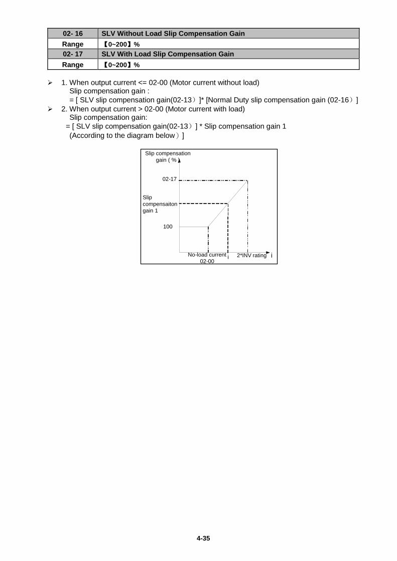
4-35
02- 16 SLV Without Load Slip Compensation Gain Range 【0~200】% 02- 17 SLV With Load Slip Compensation Gain Range 【0~200】%
1. When output current <= 02-00 (Motor current without load) Slip compensation gain : = [ SLV slip compensation gain(02-13)]* [Normal Duty slip compensation gain (02-16)] 2. When output current > 02-00 (Motor current with load) Slip compensation gain: = [ SLV slip compensation gain(02-13)] * Slip compensation gain 1 (According to the diagram below)]
i
Slip compensation gain ( % )
No-load current02-00
2*INV ratingi
02-17
100
Slip compensaiton gain 1
4-36
03- External digital inputs & Relay Output functions
03- 00 Multifunction Input Term. S1 03- 01 Multifunction Input Term. S2 03- 02 Multifunction Input Term. S3 03- 03 Multifunction Input Term. S4 03- 04 Multifunction Input Term. S5
Range
【0】:Forward/Stop Command-------------------(Parameters 00- 02/00-03=1 & 00-04)
【1】:Reverse/Stop Command---------------------(Parameters 00-02/00-03=1 & 00-04)
【2】:Preset Speed 1 (5- 02)--------------------- (Parameter Group5)
【3】:Preset Speed 2 (5- 03)----------------------(Parameter Group5)
【4】:Preset Speed 4 (5- 05) ---------------------(Parameter Group5)
【6】:JOG Forward Command-------------------(Parameters 00-18~00-20)
【7】:JOG Reverse Command------------------ (Parameters 00-18~00-20)
【8】:Up Command--------------------------- (Parameters 00- 05/00- 06=4& 03-06/03-07)
【9】:Down Command----------------------- (Parameters 00- 05/00- 06=4& 03-06/03-07) 【10】: 2nd Acc/Dec times 【11】: Disable Acc/Dec
【12】: Main/ Alternative run source Select-----------------(Parameters 00- 02/00- 03)
【13】: Main/Alternative Frequency Command Select----(Parameters 00- 05/00- 06)
【14】: Rapid Stop (controlled deceleration stop)
【15】: Base Block (Coast to stop)
【16】: Disable PID Function.----------------------------------(Parameter Goup10)
【17】: Reset
【18】: Enable Auto Run Mode--------------------------------(Parameter Group 6) Various example settings and descriptions for Parameters 03-00 to 03-04 are noted in the following pages seconds from 1 to 13.
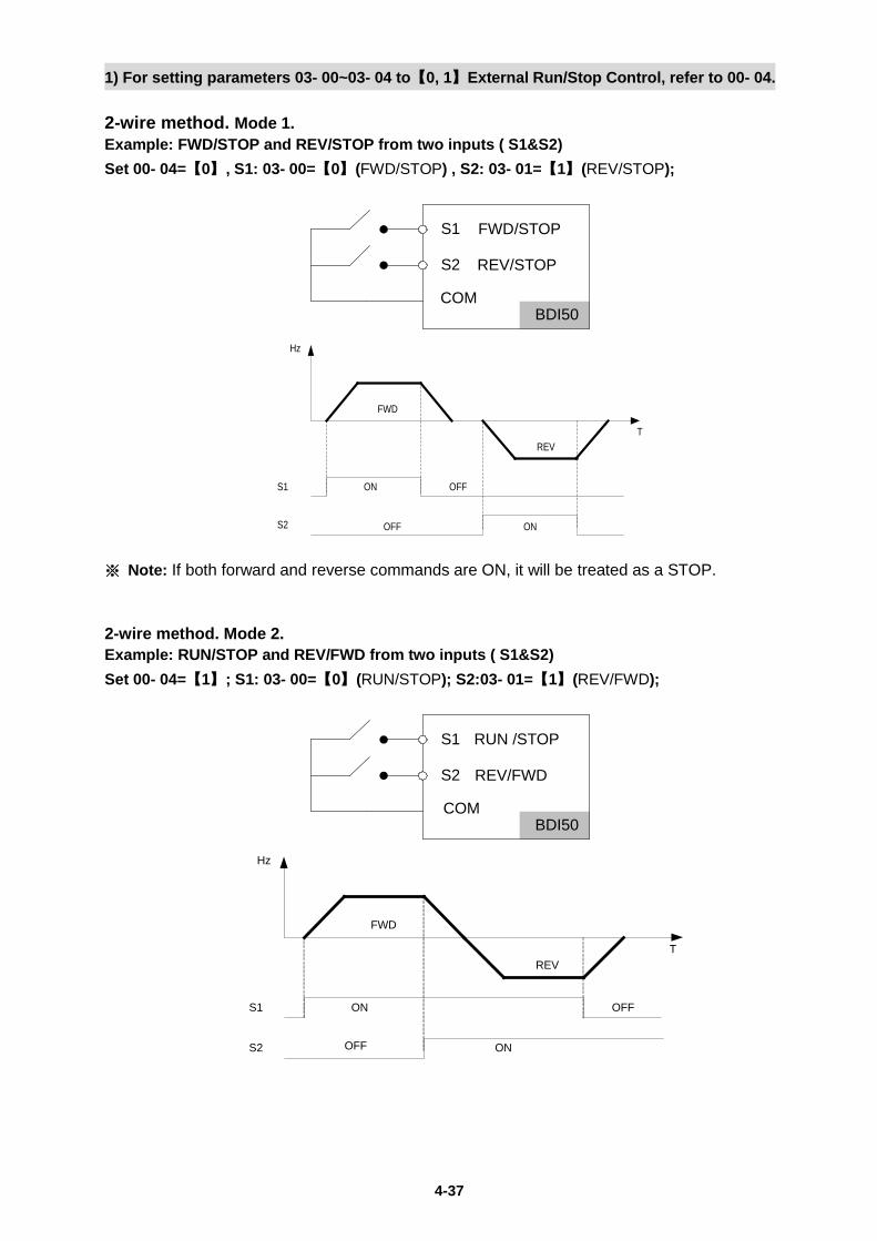
4-37
1) For setting parameters 03- 00~03- 04 to【0, 1】External Run/Stop Control, refer to 00- 04. 2-wire method. Mode 1. Example: FWD/STOP and REV/STOP from two inputs ( S1&S2) Set 00- 04=【0】, S1: 03- 00=【0】(FWD/STOP) , S2: 03- 01=【1】(REV/STOP);
S1 ON OFF
FWD
REV
ONOFFS2
Hz
T
※ Note: If both forward and reverse commands are ON, it will be treated as a STOP. 2-wire method. Mode 2. Example: RUN/STOP and REV/FWD from two inputs ( S1&S2) Set 00- 04=【1】; S1: 03- 00=【0】(RUN/STOP); S2:03- 01=【1】(REV/FWD);
S1 ON OFF
FWD
REV
S2
T
Hz
ONOFF
BDI50
S1
S2
COM
FWD/STOP
REV/STOP
BDI50
S1
S2
COM
RUN /STOP
REV/FWD
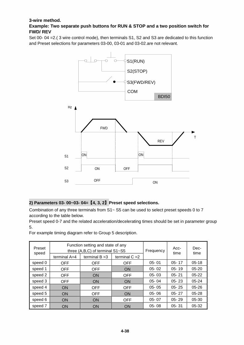
4-38
3-wire method. Example: Two separate push buttons for RUN & STOP and a two position switch for FWD/ REV Set 00- 04 =2.( 3 wire control mode), then terminals S1, S2 and S3 are dedicated to this function and Preset selections for parameters 03-00, 03-01 and 03-02.are not relevant.
S1
OFF
FWD
REV
S2
S3
ON
ON ON
Hz
T
OFF ON 2) Parameters 03- 00~03- 04=【4, 3, 2】Preset speed selections. Combination of any three terminals from S1~ S5 can be used to select preset speeds 0 to 7 according to the table below. Preset speed 0-7 and the related acceleration/decelerating times should be set in parameter group 5. For example timing diagram refer to Group 5 description.
Preset speed
Function setting and state of any three (A,B,C) of terminal S1~S5 Frequency Acc-
time Dec-time
terminal A=4 terminal B =3 terminal C =2 speed 0 OFF OFF OFF 05- 01 05- 17 05-18 speed 1 OFF OFF ON 05- 02 05- 19 05-20 speed 2 OFF ON OFF 05- 03 05- 21 05-22 speed 3 OFF ON ON 05- 04 05- 23 05-24 speed 4 ON OFF OFF 05- 05 05- 25 05-26 speed 5 ON OFF ON 05- 06 05- 27 05-28 speed 6 ON ON OFF 05- 07 05- 29 05-30 speed 7 ON ON ON 05- 08 05- 31 05-32
BDI50
S1(RUN)
S2(STOP)
S3(FWD/REV)
COM
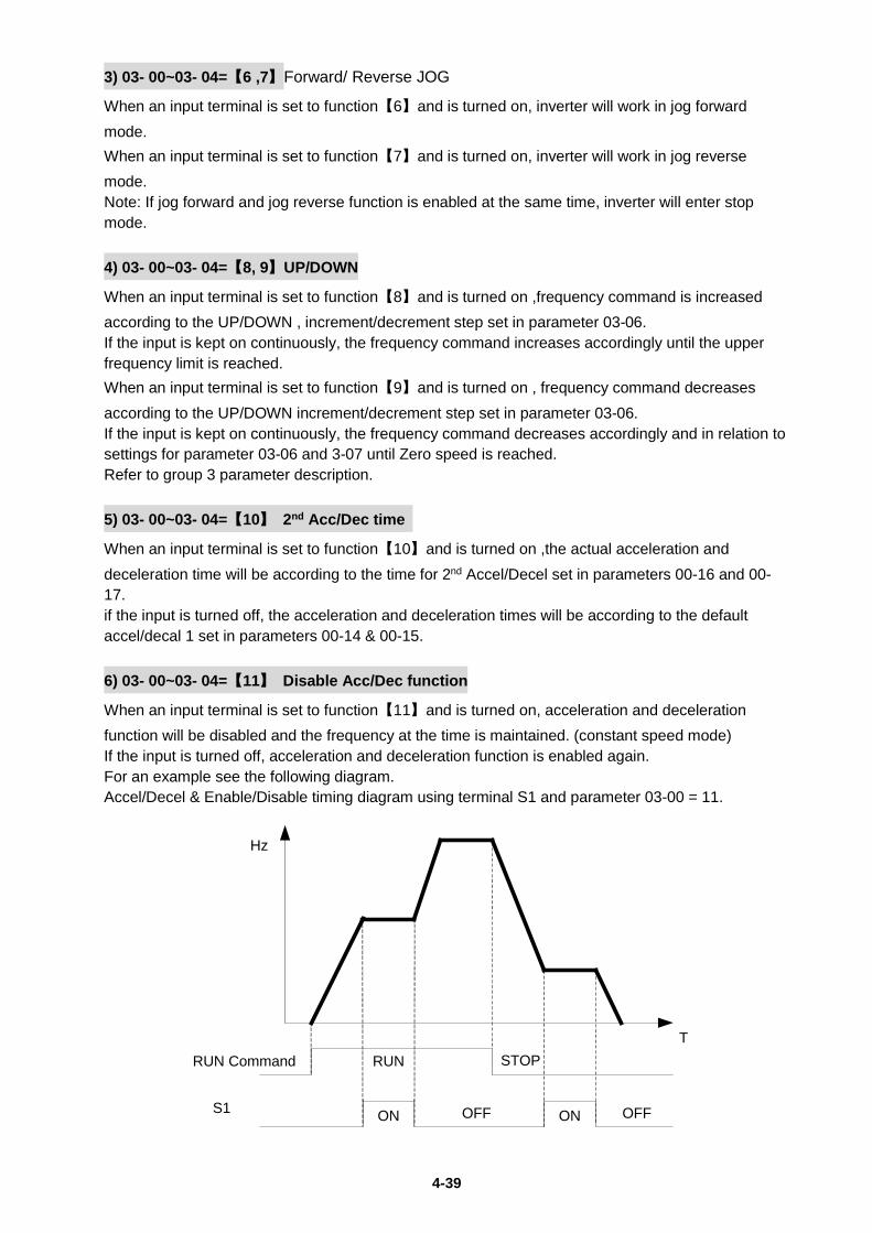
4-39
3) 03- 00~03- 04=【6 ,7】Forward/ Reverse JOG
When an input terminal is set to function【6】and is turned on, inverter will work in jog forward mode. When an input terminal is set to function【7】and is turned on, inverter will work in jog reverse mode. Note: If jog forward and jog reverse function is enabled at the same time, inverter will enter stop mode. 4) 03- 00~03- 04=【8, 9】UP/DOWN
When an input terminal is set to function【8】and is turned on ,frequency command is increased according to the UP/DOWN , increment/decrement step set in parameter 03-06. If the input is kept on continuously, the frequency command increases accordingly until the upper frequency limit is reached. When an input terminal is set to function【9】and is turned on , frequency command decreases according to the UP/DOWN increment/decrement step set in parameter 03-06. If the input is kept on continuously, the frequency command decreases accordingly and in relation to settings for parameter 03-06 and 3-07 until Zero speed is reached. Refer to group 3 parameter description. 5) 03- 00~03- 04=【10】 2nd Acc/Dec time
When an input terminal is set to function【10】and is turned on ,the actual acceleration and deceleration time will be according to the time for 2nd Accel/Decel set in parameters 00-16 and 00-17. if the input is turned off, the acceleration and deceleration times will be according to the default accel/decal 1 set in parameters 00-14 & 00-15. 6) 03- 00~03- 04=【11】 Disable Acc/Dec function
When an input terminal is set to function【11】and is turned on, acceleration and deceleration function will be disabled and the frequency at the time is maintained. (constant speed mode) If the input is turned off, acceleration and deceleration function is enabled again. For an example see the following diagram. Accel/Decel & Enable/Disable timing diagram using terminal S1 and parameter 03-00 = 11.
RUN Command
S1
RUN STOP
ON OFF ON OFF
T
Hz
4-40
7) 03- 00~03- 04=【12】Main/ Alternative run source select. When an input terminal is set to function【12】and is turned on, the run command source is according to parameter 00-03(Alternative Run source).If the Input is off it will be according to 00-02 ( Main run source). 8) 03- 00~03- 04=【13】Main/ Alternative Frequency source Select
When an input terminal is set to function【13】and is turned on, the frequency source is according to parameter 00-06(Alternative Frequency source).If the Input is off it will be according to 00-05 ( Main Frequency source). 9) 03- 00~03- 04=【14】Rapid Stop (controlled deceleration stop) When DI is on, motor decelerates to stop. When turning off DI (remove ES), BDI50 won’t run again. BDI50 runs again only after giving Run command again. 10) 03- 00~03- 04=【15】Base Block (Coast to stop) When DI is on, motor free runs to stop. When turning off DI (remove BB), BDI50 will start running from 5Hz below the set frequency, to 5Hz above the set frequency, and then back to the set frequency. 11) 03- 00~03- 04=【16】Disable PID Function.
When an input terminal is set to function【16】and is turned on, PID functions is disabled, if it is turned off , PID function is enabled again. 12) 03- 00~03- 04=【17】Reset
When a failure that can be manually reset occurs, turn on a terminal with function 【17】, the failure will be reset. (Same function as the Reset button on keypad). 13) 03- 00~03- 04=【18】Auto _ Run Mode
When an input terminal is set to function【18】, the programmable auto- sequencer function is enabled, Refer to description of parameter group 6.
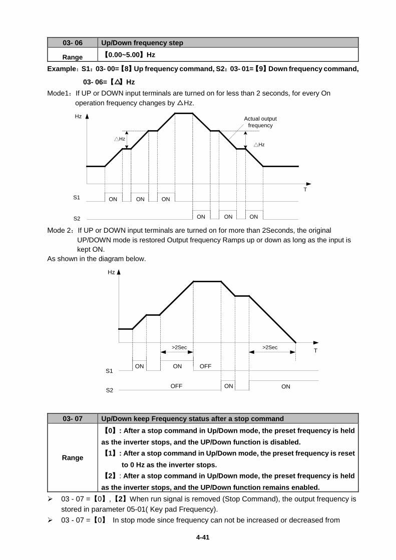
4-41
03- 06 Up/Down frequency step
Range 【0.00~5.00】Hz
Example:S1:03- 00=【8】Up frequency command, S2:03- 01=【9】Down frequency command,
03- 06=【△】Hz Mode1:If UP or DOWN input terminals are turned on for less than 2 seconds, for every On
operation frequency changes by △ Hz.
S1
S2
ON ON ON
Hz
T
△Hz
Actual output frequency
ON ON ON
△Hz
Mode 2:If UP or DOWN input terminals are turned on for more than 2Seconds, the original
UP/DOWN mode is restored Output frequency Ramps up or down as long as the input is kept ON.
As shown in the diagram below.
S1
S2
ON ON
ON
>2Sec
OFF
OFF
>2Sec T
Hz
ON
03- 07 Up/Down keep Frequency status after a stop command
Range
【0】: After a stop command in Up/Down mode, the preset frequency is held as the inverter stops, and the UP/Down function is disabled. 【1】: After a stop command in Up/Down mode, the preset frequency is reset
to 0 Hz as the inverter stops. 【2】: After a stop command in Up/Down mode, the preset frequency is held as the inverter stops, and the UP/Down function remains enabled.
03 - 07 =【0】,【2】When run signal is removed (Stop Command), the output frequency is stored in parameter 05-01( Key pad Frequency).
03 - 07 =【0】 In stop mode since frequency can not be increased or decreased from
4-42
Up/Down terminals then keypad can be used to change the frequency by modifying parameter 05-01.
03 - 07 =【1】In Up/down frequency mode inverter will ramp up from 0Hz on Run
command and Ramp down to 0 Hz on stop command.
03- 08 Multifunction terminals S1~S5 scan time Range 【1~200】 2ms
Multifunction input terminal On/Off periods will be scanned for the number of cycles according to the set value in parameter 03-08. If the signal status for On or off period is less than the set period it will be treated as noise.
Scan period unit is 1ms. Use this parameter if unstable input signal is expected, however setting long scan time periods
results in slower response times.
03- 09 s1~s5 Input type selection NO & NC
Range
【xxxx0】:S1 NO 【xxxx1】:S1 NC
【xxx0x】:S2 NO 【xxx1x】:S2 NC
【xx0xx】:S3 NO 【xx1xx】:S3 NC
【x0xxx】:S4 NO 【x1xxx】:S4 NC
【0xxxx】:S5 NO 【1xxxx】:S5 NC (NO) Normally open, (NC) Normally closed. Select as required. For selecting Normally Open (NO) or Normally Closed(NC) set the relevant digit in
parameter 03-09 to 0 or 1 as required. Set Parameter 03-09 first before you use the Parameters 00-02/00-03=1 to set the
inverter run mode to External multifunction inputs.
03-11 Multifunction Output Relay RY1 functions. ( Terminals RB, RA )
Range
【0】:Run
【1】:Fault
【2】:Setting Frequency Reached -------------------------------( refer to 03-14)
【3】:Frequency Reached (3-13±3-14) -------------------------( refer to 03-13/03-14)
【4】:Output Frequency Detection 1 (> 03-13) ----------( refer to 03-13)
【5】:Output Frequency Detection 2 (< 03-13) ----------( refer to 03-13)
【6】:Auto-Restart
【7】:Momentary AC Power Loss----------------------------( refer to 07-00)
【8】:Rapid Stop ( Decelerate to Stop)
【9】:Base Block
【10】:Motor Overload Protection (OL1)
【11】:Drive Overload Protection (OL2)
【12】:Reserved
【13】:Output Current Reached ---------------------------------(refer to 03-15/03-16)
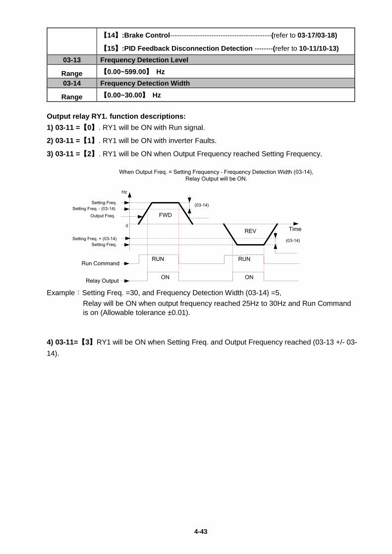
4-43
【14】:Brake Control--------------------------------------------(refer to 03-17/03-18)
【15】:PID Feedback Disconnection Detection --------(refer to 10-11/10-13) 03-13 Frequency Detection Level
Range 【0.00~599.00】 Hz 03-14 Frequency Detection Width
Range 【0.00~30.00】 Hz Output relay RY1. function descriptions: 1) 03-11 =【0】. RY1 will be ON with Run signal.
2) 03-11 =【1】. RY1 will be ON with inverter Faults.
3) 03-11 =【2】. RY1 will be ON when Output Frequency reached Setting Frequency.
FWD
REV
Setting Freq. (03-14)
When Output Freq. = Setting Frequency – Frequency Detection Width (03-14), Relay Output will be ON.
Output Freq.
ON ONRelay Output
Hz
Time0
RUN RUNRun Command
Setting Freq. – (03-14)
(03-14)Setting Freq. + (03-14)Setting Freq.
Example:Setting Freq. =30, and Frequency Detection Width (03-14) =5,
Relay will be ON when output frequency reached 25Hz to 30Hz and Run Command is on (Allowable tolerance ±0.01).
4) 03-11=【3】RY1 will be ON when Setting Freq. and Output Frequency reached (03-13 +/- 03-14).
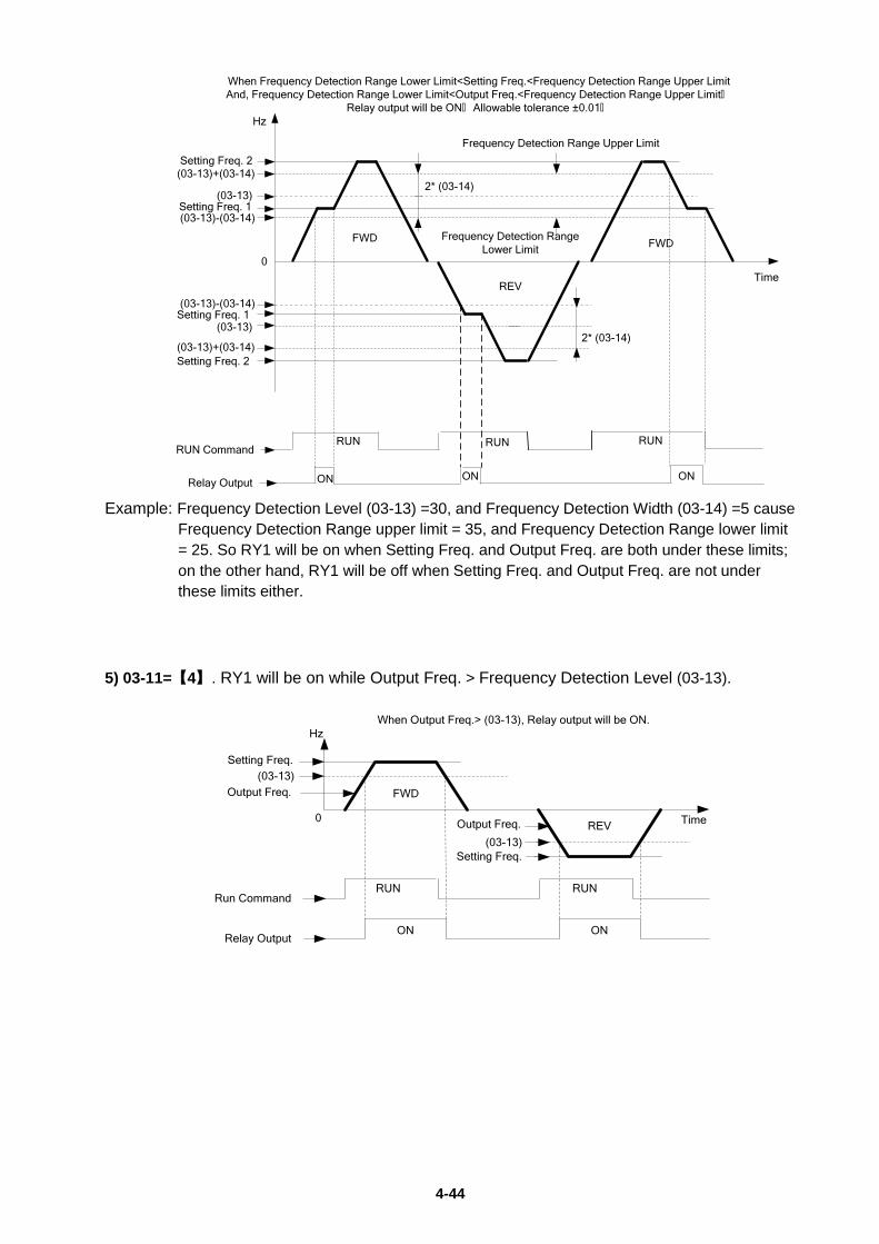
4-44
FWD
REV
Setting Freq. 2
Setting Freq. 1
Setting Freq. 1
Setting Freq. 2
2* (03-14)
Relay Output ON ON ON
RUN RUNRUNRUN Command
FWD
Hz
Time0
When Frequency Detection Range Lower Limit<Setting Freq.<Frequency Detection Range Upper LimitAnd, Frequency Detection Range Lower Limit<Output Freq.<Frequency Detection Range Upper Limit,
Relay output will be ON, Allowable tolerance ±0.01,
(03-13)
(03-13)+(03-14)
(03-13)-(03-14)
(03-13)
(03-13)-(03-14)
(03-13)+(03-14)2* (03-14)
Frequency Detection Range Upper Limit
Frequency Detection Range Lower Limit
Example: Frequency Detection Level (03-13) =30, and Frequency Detection Width (03-14) =5 cause
Frequency Detection Range upper limit = 35, and Frequency Detection Range lower limit = 25. So RY1 will be on when Setting Freq. and Output Freq. are both under these limits; on the other hand, RY1 will be off when Setting Freq. and Output Freq. are not under these limits either.
5) 03-11=【4】. RY1 will be on while Output Freq. > Frequency Detection Level (03-13).
When Output Freq.> (03-13), Relay output will be ON.
FWD
REV
Setting Freq.
Setting Freq.
Output Freq.
Output Freq.
RUN RUN
ON ON
Run Command
Relay Output
(03-13)
(03-13)
Hz
Time0
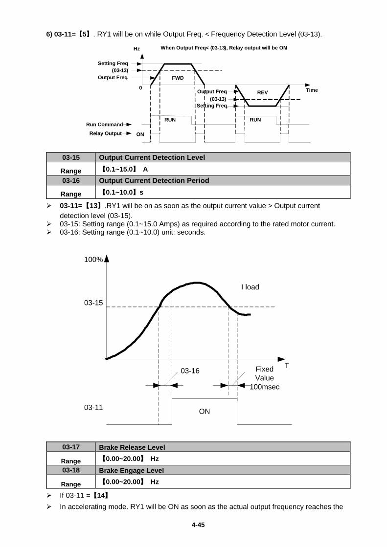
4-45
6) 03-11=【5】. RY1 will be on while Output Freq. < Frequency Detection Level (03-13).
03-15 Output Current Detection Level
Range 【0.1~15.0】 A 03-16 Output Current Detection Period
Range 【0.1~10.0】s
03-11=【13】.RY1 will be on as soon as the output current value > Output current detection level (03-15).
03-15: Setting range (0.1~15.0 Amps) as required according to the rated motor current. 03-16: Setting range (0.1~10.0) unit: seconds.
03-16 Fixed Value
100msec
03-15
03-11 ON
I load
100%
T
03-17 Brake Release Level
Range 【0.00~20.00】 Hz 03-18 Brake Engage Level
Range 【0.00~20.00】 Hz
If 03-11 =【14】 In accelerating mode. RY1 will be ON as soon as the actual output frequency reaches the
When Output Freq.< (03-13), Relay output will be ON.
FWD
REV
Setting Freq.
Setting Freq.
Output Freq.
Output Freq.
RUN RUN
ON
Run CommandRelay Output
(03-13)
(03-13)
Hz
Time0
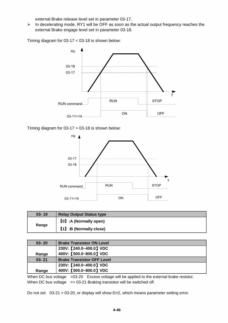
4-46
external Brake release level set in parameter 03-17. In decelerating mode, RY1 will be OFF as soon as the actual output frequency reaches the
external Brake engage level set in parameter 03-18. Timing diagram for 03-17 < 03-18 is shown below:
03-17
03-18
03-11=14
RUN command
Hz
T
ON OFF
RUN STOP
Timing diagram for 03-17 > 03-18 is shown below:
03-18
03-17
RUN command
03-11=14
Hz
T
ON OFF
RUN STOP
03- 19 Relay Output Status type
Range 【0】:A (Normally open)
【1】:B (Normally close)
03- 20 Brake Transistor ON Level
Range 230V:【240.0~400.0】VDC 400V:【500.0~800.0】VDC
03- 21 Brake Transistor OFF Level
Range 230V:【240.0~400.0】VDC 400V:【500.0~800.0】VDC
When DC bus voltage >03-20 Excess voltage will be applied to the external brake resistor. When DC bus voltage <= 03-21 Braking transistor will be switched off. Do not set 03-21 > 03-20, or display will show Err2, which means parameter setting error.
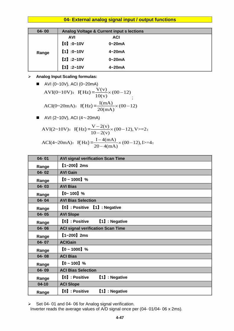
4-47
04- External analog signal input / output functions
04- 00 Analog Voltage & Current input s lections
Range
AVI ACI 【0】:0~10V 0~20mA
【1】:0~10V 4~20mA
【2】:2~10V 0~20mA
【3】:2~10V 4~20mA
Analog Input Scaling formulas:
AVI (0~10V), ACI (0~20mA) V(v)AVI(0~10V) F Hz (00 12)10(v)
× −: ( ) =;
I(mA)ACI(0~20mA) F Hz (00 12)20(mA)
× −: ( ) =
AVI (2~10V), ACI (4~20mA)
V 2(v)AVI(2~10V) F Hz (00 12),V>=210 2(v)−
× −−
: ( ) = ;
I 4(mA)ACI(4~20mA) F Hz (00 12), I>=420 4(mA)−
× −−
: ( ) = ;
04- 01 AVI signal verification Scan Time
Range 【1~200】2ms 04- 02 AVI Gain
Range 【0 ~ 1000】% 04- 03 AVI Bias
Range 【0~ 100】% 04- 04 AVI Bias Selection
Range 【0】: Positive 【1】: Negative 04- 05 AVI Slope
Range 【0】: Positive 【1】: Negative 04- 06 ACI signal verification Scan Time
Range 【1~200】2ms 04- 07 ACIGain
Range 【0 ~ 1000】% 04- 08 ACI Bias
Range 【0 ~ 100】% 04- 09 ACI Bias Selection
Range 【0】: Positive 【1】: Negative 04-10 ACI Slope
Range 【0】: Positive 【1】: Negative Set 04- 01 and 04- 06 for Analog signal verification. Inverter reads the average values of A/D signal once per (04- 01/04- 06 x 2ms).
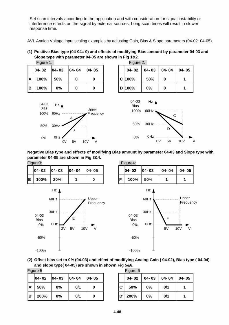
4-48
Set scan intervals according to the application and with consideration for signal instability or interference effects on the signal by external sources. Long scan times will result in slower response time.
AVI. Analog Voltage input scaling examples by adjusting Gain, Bias & Slope parameters (04-02~04-05). (1) Positive Bias type (04-04= 0) and effects of modifying Bias amount by parameter 04-03 and
Slope type with parameter 04-05 are shown in Fig 1&2. Figure 1. Figure 2.
04- 02 04- 03 04- 04 04- 05 04- 02 04- 03 04- 04 04- 05
A 100% 50% 0 0 C 100% 50% 0 1
B 100% 0% 0 0 D 100% 0% 0 1
60Hz
30Hz
0Hz0V 5V 10V
Hz
V
04-03Bias
100%
50%
0%
Upper Frequency
A
B
60Hz
30Hz
0Hz0V 5V 10V
Hz
V
100%
50%
0%
C
D
04-03Bias
Negative Bias type and effects of modifying Bias amount by parameter 04-03 and Slope type with parameter 04-05 are shown in Fig 3&4. Figure3: Figure4: 04- 02 04- 03 04- 04 04- 05 04- 02 04- 03 04- 04 04- 05
E 100% 20% 1 0 F 100% 50% 1 1
60Hz
30Hz
0Hz2V 5V 10V
Hz
V
04-03Bias
-100%
-50%
-0%
E
Upper Frequency
60Hz
30Hz
0Hz5V 10V
Hz
V
04-03Bias
-100%
-50%
-0%
F
Upper Frequency
(2) Offset bias set to 0% (04-03) and effect of modifying Analog Gain ( 04-02), Bias type ( 04-04)
and slope type( 04-05) are shown in shown Fig 5&6. Figure 5 Figure 6 04- 02 04- 03 04- 04 04- 05 04- 02 04- 03 04- 04 04- 05
A' 50% 0% 0/1 0 C' 50% 0% 0/1 1
B' 200% 0% 0/1 0 D' 200% 0% 0/1 1
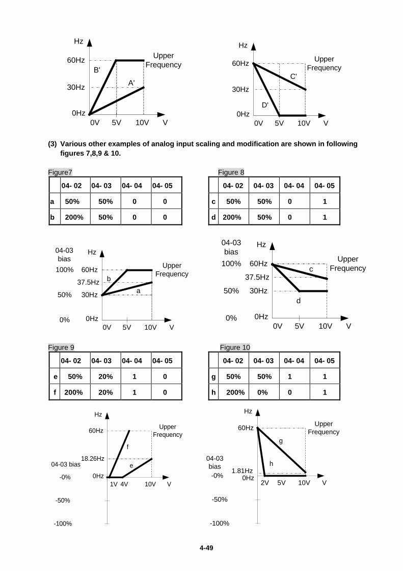
4-49
60Hz
30Hz
0Hz0V 5V 10V
Hz
V
Upper Frequency
B'
A'
60Hz
30Hz
0Hz0V 5V 10V
Hz
V
Upper Frequency
D'
C'
(3) Various other examples of analog input scaling and modification are shown in following
figures 7,8,9 & 10. Figure7 Figure 8 04- 02 04- 03 04- 04 04- 05 04- 02 04- 03 04- 04 04- 05
a 50% 50% 0 0 c 50% 50% 0 1
b 200% 50% 0 0 d 200% 50% 0 1
60Hz
30Hz
0Hz0V 5V 10V
Hz
V
04-03bias
100%
50%
0%
UpperFrequency
b
a37.5Hz
60Hz
30Hz
0Hz0V 5V 10V
Hz
V
04-03bias
100%
50%
0%
UpperFrequencyc
d
37.5Hz
Figure 9 Figure 10 04- 02 04- 03 04- 04 04- 05 04- 02 04- 03 04- 04 04- 05
e 50% 20% 1 0 g 50% 50% 1 1
f 200% 20% 1 0 h 200% 0% 0 1
60Hz
18.26Hz
0Hz1V 4V 10V
Hz
V
04-03 bias
-100%
-50%
-0%
Upper Frequency
e
f
60Hz
1.81Hz0Hz
2V 10V
Hz
V
04-03bias
-100%
-50%
-0%
Upper Frequency
h
5V
g
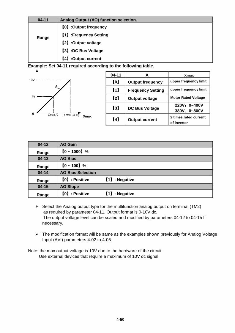
4-50
04-11 Analog Output (AO) function selection.
Range
【0】:Output frequency
【1】:Frequency Setting
【2】:Output voltage
【3】:DC Bus Voltage
【4】:Output current Example: Set 04-11 required according to the following table.
0
10V
Xmax
A
Xmax( 04-11)Xmax / 2
5 V
04-12 AO Gain
Range 【0 ~ 1000】% 04-13 AO Bias
Range 【0 ~ 100】% 04-14 AO Bias Selection
Range 【0】: Positive 【1】: Negative 04-15 AO Slope
Range 【0】: Positive 【1】: Negative Select the Analog output type for the multifunction analog output on terminal (TM2)
as required by parameter 04-11. Output format is 0-10V dc. The output voltage level can be scaled and modified by parameters 04-12 to 04-15 If
necessary. The modification format will be same as the examples shown previously for Analog Voltage
Input (AVI) parameters 4-02 to 4-05. Note: the max output voltage is 10V due to the hardware of the circuit. Use external devices that require a maximum of 10V dc signal.
04-11 A Xmax
【0】 Output frequency upper frequency limit
【1】 Frequency Setting upper frequency limit
【2】 Output voltage Motor Rated Voltage
【3】 DC Bus Voltage 220V:0~400V 380V:0~800V
【4】 Output current 2 times rated current of inverter
4-51
05- Preset Frequency Selections.
05- 00 Preset Speed Control mode Selection
Range
【0】:Common Accel / Decel.
【1】: Individual Accel/Decel for each preset speed 0-7.
05- 01 Preset Speed 0 (Keypad Freq) 05- 02 Preset Speed 1 05- 03 Preset Speed 2 05- 04 Preset Speed 3 05- 05 Preset Speed 4 05- 06 Preset Speed 5 05- 07 Preset Speed 6 05- 08 Preset Speed 7
Range 【0.00 ~ 599.00】 Hz 05-17 Preset Speed 0 Acceleration time 05-18 Preset Speed 0 Deceleration time 05-19 Preset Speed 1 Acceleration time 05- 20 Preset Speed 1 Deceleration time 05- 21 Preset Speed 2 Acceleration time 05- 22 Preset Speed 2 Deceleration time 05- 23 Preset Speed 3 Acceleration time 05- 24 Preset Speed 3 Deceleration time 05- 25 Preset Speed 4 Acceleration time 05- 26 Preset Speed 4 Deceleration time 05- 27 Preset Speed 5 Acceleration time 05- 28 Preset Speed 5 Deceleration time 05- 29 Preset Speed 6 Acceleration time 05- 30 Preset Speed 6 Deceleration time 05- 31 Preset Speed 7 Acceleration time 05- 32 Preset Speed 7 Deceleration time
Range 【0.1 ~ 3600.0】s
When 05- 00 =【0】Accel /Decl 1 or 2 set by parameters 00-14/00-15 or 00-16/00-17 apply to all speeds.
When 05- 00 =【1】Individual Accel/Decel apply to each preset speed 0-7. Parameters 05-17 to 05-32.
Formula for calculating acceleration and deceleration time: V/F mode:
Actual Acc time = Time of Accel 1 or 2 x Preset Frequency V/F Max Frequency
Actual Dec time = Time of Decel 1 or 2 x Preset Frequency
V/F Max Frequency SLV mode:
Actual Acc time = Time of Accel 1 or 2 x Preset Frequency Motor rated output frequency
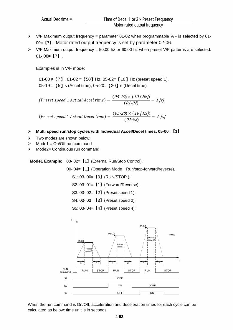
4-52
Actual Dec time = Time of Decel 1 or 2 x Preset Frequency Motor rated output frequency
V/F Maximum output frequency = parameter 01-02 when programmable V/F is selected by 01-
00=【7】. Motor rated output frequency is set by parameter 02-06. V/F Maximum output frequency = 50.00 hz or 60.00 hz when preset V/F patterns are selected.
01- 00≠【7】. Examples is in V/F mode:
01-00 ≠【7】, 01-02 =【50】Hz, 05-02=【10】Hz (preset speed 1), 05-19 =【5】s (Accel time), 05-20=【20】s (Decel time)
(𝑃𝑃𝑃𝑃𝑃𝑃𝑃𝑃𝑃𝑃𝑃𝑃 𝑃𝑃𝑠𝑠𝑃𝑃𝑃𝑃𝑠𝑠 1 𝐴𝐴𝐴𝐴𝑃𝑃𝐴𝐴𝐴𝐴𝐴𝐴 𝐴𝐴𝐴𝐴𝐴𝐴𝑃𝑃𝐴𝐴 𝑃𝑃𝑡𝑡𝑡𝑡𝑃𝑃) = (05-19) × (10 [ Hz])
(01-02) = 1 [s]
(𝑃𝑃𝑃𝑃𝑃𝑃𝑃𝑃𝑃𝑃𝑃𝑃 𝑃𝑃𝑠𝑠𝑃𝑃𝑃𝑃𝑠𝑠 1 𝐴𝐴𝐴𝐴𝑃𝑃𝐴𝐴𝐴𝐴𝐴𝐴 𝐷𝐷𝑃𝑃𝐴𝐴𝑃𝑃𝐴𝐴 𝑃𝑃𝑡𝑡𝑡𝑡𝑃𝑃) = (05-20) × (10 [ Hz])
(01-02) = 4 [s]
Multi speed run/stop cycles with Individual Accel/Decel times. 05-00=【1】 Two modes are shown below: Mode1 = On/Off run command Mode2= Continuous run command Mode1 Example: 00- 02=【1】(External Run/Stop Control).
00- 04=【1】(Operation Mode:Run/stop-forward/reverse).
S1: 03- 00=【0】(RUN/STOP );
S2: 03- 01=【1】(Forward/Reverse);
S3: 03- 02=【2】(Preset speed 1);
S4: 03- 03=【3】(Preset speed 2);
S5: 03- 04=【4】(Preset speed 4);
a b c d e f
RUN RUN RUN
ON
ON
STOP STOP STOP
OFF
OFF
RUN command
S2
S3
S4
05-01
05-02
05-03
Presetspeed0
Presetspeed1
Presetspeed2
Hz
T
FWD
OFF
When the run command is On/Off, acceleration and deceleration times for each cycle can be calculated as below: time unit is in seconds.
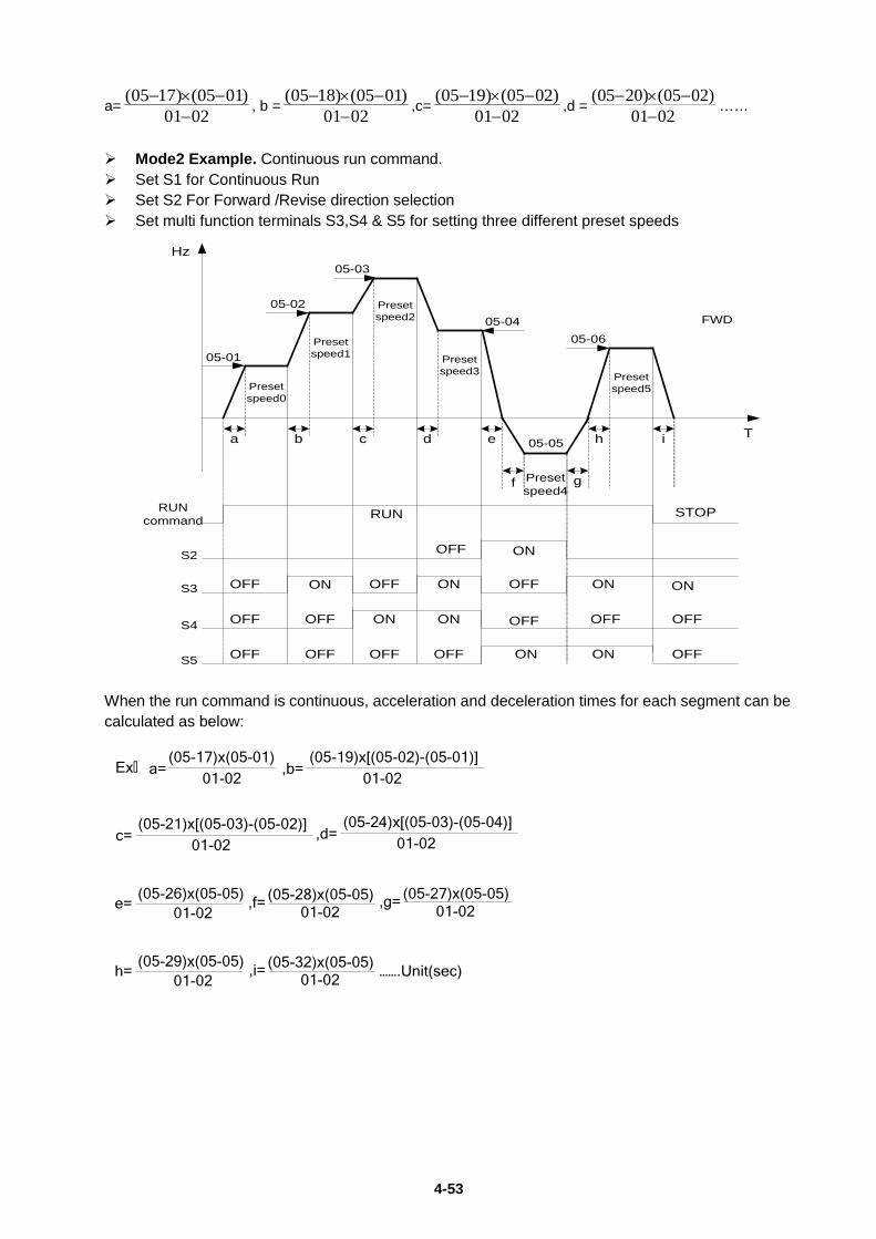
4-53
a=(05 17) (05 01)
01 02− × −
−, b =
(05 18) (05 01)01 02
− × −−
,c=(05 19) (05 02)
01 02− × −
−,d =
(05 20) (05 02)01 02
− × −−
……
Mode2 Example. Continuous run command. Set S1 for Continuous Run Set S2 For Forward /Revise direction selection Set multi function terminals S3,S4 & S5 for setting three different preset speeds
05-01
05-02
05-03
05-0405-06
05-05
ON
OFF ON
OFF ON
OFF
a b c d e
f g
h i
FWD
T
Hz
S2
S3
S4
S5
RUN command
Presetspeed0
Presetspeed1
Presetspeed2
Presetspeed3
Presetspeed4
Presetspeed5
RUN STOP
ONOFF
OFF
OFF OFF
OFF
OFF
ON
ON
ON
ON
OFF
OFF OFF OFF
OFF
ON
When the run command is continuous, acceleration and deceleration times for each segment can be calculated as below:
Ex,(05-17)x(05-01)
01-02a=
(05-19)x[(05-02)-(05-01)]01-02
,b=
(05-21)x[(05-03)-(05-02)]01-02
c=(05-24)x[(05-03)-(05-04)]
01-02,d=
(05-26)x(05-05)01-02
e= (05-28)x(05-05)01-02
,f= (05-27)x(05-05)01-02
,g=
(05-29)x(05-05)01-02
h= (05-32)x(05-05)01-02
,i= …….Unit(sec)
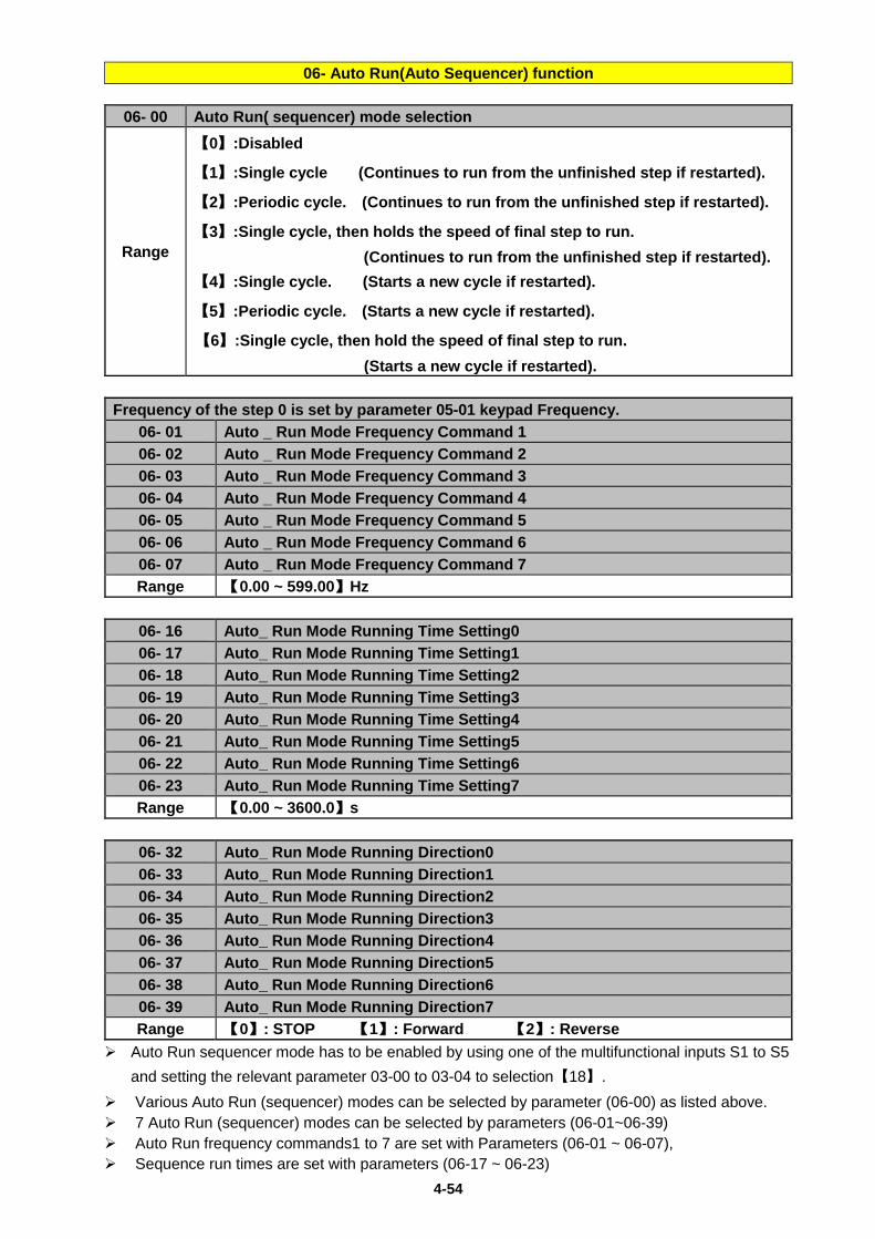
4-54
06- Auto Run(Auto Sequencer) function
06- 00 Auto Run( sequencer) mode selection
Range
【0】:Disabled
【1】:Single cycle (Continues to run from the unfinished step if restarted).
【2】:Periodic cycle. (Continues to run from the unfinished step if restarted).
【3】:Single cycle, then holds the speed of final step to run. (Continues to run from the unfinished step if restarted). 【4】:Single cycle. (Starts a new cycle if restarted).
【5】:Periodic cycle. (Starts a new cycle if restarted).
【6】:Single cycle, then hold the speed of final step to run. (Starts a new cycle if restarted).
Frequency of the step 0 is set by parameter 05-01 keypad Frequency.
06- 01 Auto _ Run Mode Frequency Command 1 06- 02 Auto _ Run Mode Frequency Command 2 06- 03 Auto _ Run Mode Frequency Command 3 06- 04 Auto _ Run Mode Frequency Command 4 06- 05 Auto _ Run Mode Frequency Command 5 06- 06 Auto _ Run Mode Frequency Command 6 06- 07 Auto _ Run Mode Frequency Command 7 Range 【0.00 ~ 599.00】Hz
06- 16 Auto_ Run Mode Running Time Setting0 06- 17 Auto_ Run Mode Running Time Setting1 06- 18 Auto_ Run Mode Running Time Setting2 06- 19 Auto_ Run Mode Running Time Setting3 06- 20 Auto_ Run Mode Running Time Setting4 06- 21 Auto_ Run Mode Running Time Setting5 06- 22 Auto_ Run Mode Running Time Setting6 06- 23 Auto_ Run Mode Running Time Setting7 Range 【0.00 ~ 3600.0】s
06- 32 Auto_ Run Mode Running Direction0 06- 33 Auto_ Run Mode Running Direction1 06- 34 Auto_ Run Mode Running Direction2 06- 35 Auto_ Run Mode Running Direction3 06- 36 Auto_ Run Mode Running Direction4 06- 37 Auto_ Run Mode Running Direction5 06- 38 Auto_ Run Mode Running Direction6 06- 39 Auto_ Run Mode Running Direction7 Range 【0】: STOP 【1】: Forward 【2】: Reverse
Auto Run sequencer mode has to be enabled by using one of the multifunctional inputs S1 to S5 and setting the relevant parameter 03-00 to 03-04 to selection【18】.
Various Auto Run (sequencer) modes can be selected by parameter (06-00) as listed above. 7 Auto Run (sequencer) modes can be selected by parameters (06-01~06-39) Auto Run frequency commands1 to 7 are set with Parameters (06-01 ~ 06-07), Sequence run times are set with parameters (06-17 ~ 06-23)
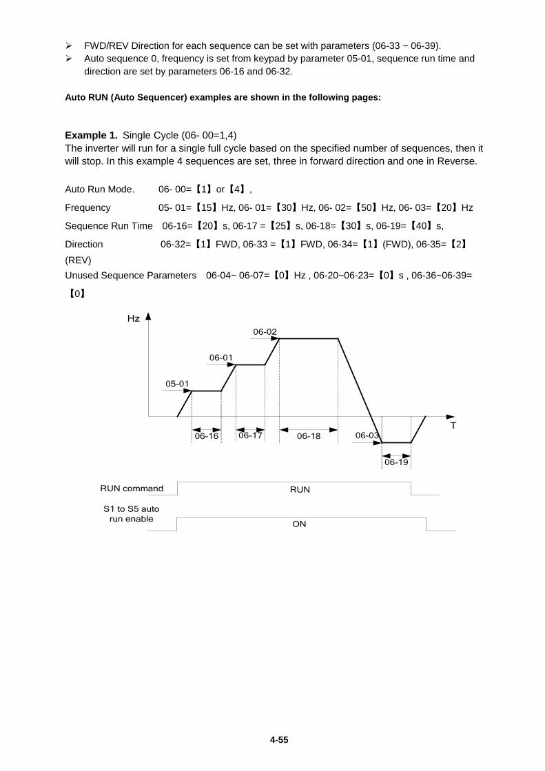
4-55
FWD/REV Direction for each sequence can be set with parameters (06-33 ~ 06-39). Auto sequence 0, frequency is set from keypad by parameter 05-01, sequence run time and
direction are set by parameters 06-16 and 06-32. Auto RUN (Auto Sequencer) examples are shown in the following pages: Example 1. Single Cycle (06- 00=1,4) The inverter will run for a single full cycle based on the specified number of sequences, then it will stop. In this example 4 sequences are set, three in forward direction and one in Reverse. Auto Run Mode. 06- 00=【1】or【4】,
Frequency 05- 01=【15】Hz, 06- 01=【30】Hz, 06- 02=【50】Hz, 06- 03=【20】Hz
Sequence Run Time 06-16=【20】s, 06-17 =【25】s, 06-18=【30】s, 06-19=【40】s,
Direction 06-32=【1】FWD, 06-33 =【1】FWD, 06-34=【1】(FWD), 06-35=【2】(REV) Unused Sequence Parameters 06-04~ 06-07=【0】Hz , 06-20~06-23=【0】s , 06-36~06-39=
【0】
05-01
06-01
06-02
06-0306-16 06-17 06-18
06-19
T
Hz
RUN command RUN
ON
S1 to S5 auto run enable
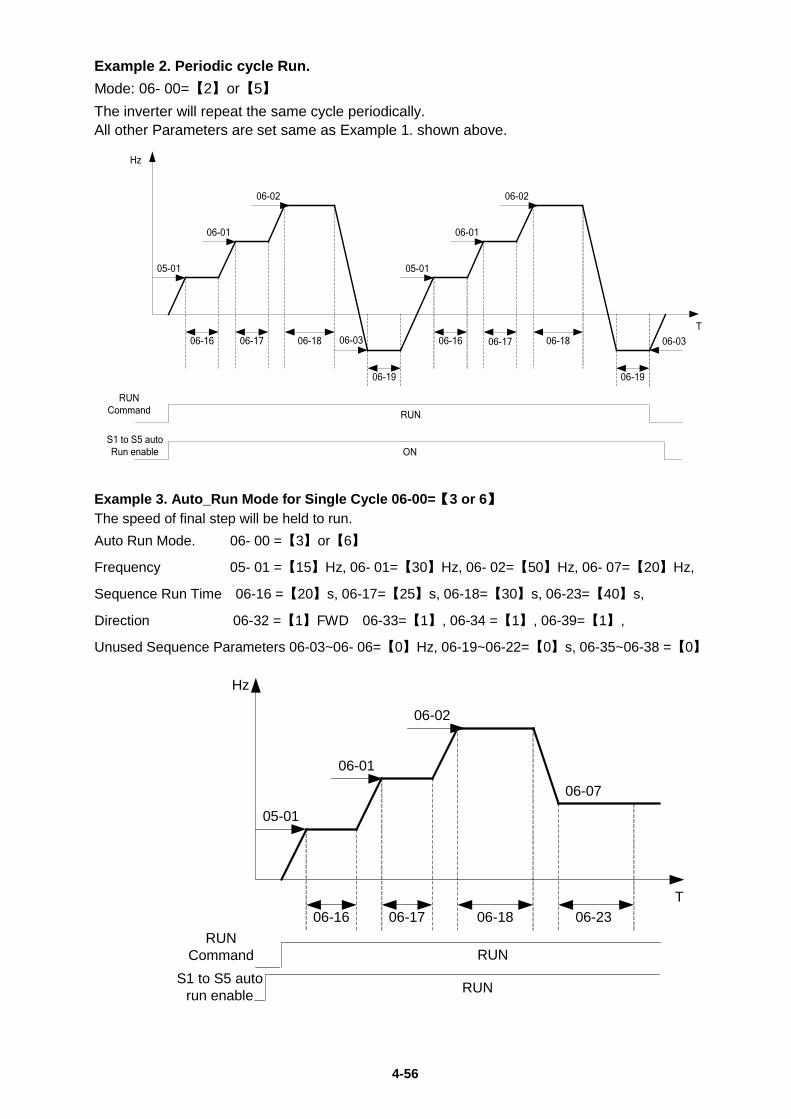
4-56
Example 2. Periodic cycle Run. Mode: 06- 00=【2】or【5】 The inverter will repeat the same cycle periodically. All other Parameters are set same as Example 1. shown above.
05-01
06-01
06-02
06-03
05-01
06-01
06-02
06-0306-16 06-17 06-18
06-19
06-16 06-17 06-18
06-19
T
Hz
RUN Command RUN
ONS1 to S5 autoRun enable
Example 3. Auto_Run Mode for Single Cycle 06-00=【3 or 6】 The speed of final step will be held to run. Auto Run Mode. 06- 00 =【3】or【6】
Frequency 05- 01 =【15】Hz, 06- 01=【30】Hz, 06- 02=【50】Hz, 06- 07=【20】Hz,
Sequence Run Time 06-16 =【20】s, 06-17=【25】s, 06-18=【30】s, 06-23=【40】s,
Direction 06-32 =【1】FWD 06-33=【1】, 06-34 =【1】, 06-39=【1】,
Unused Sequence Parameters 06-03~06- 06=【0】Hz, 06-19~06-22=【0】s, 06-35~06-38 =【0】
05-01
06-01
06-02
06-16 06-17 06-18 06-23
Hz
06-07
T
RUN Command RUN
RUNS1 to S5 auto run enable
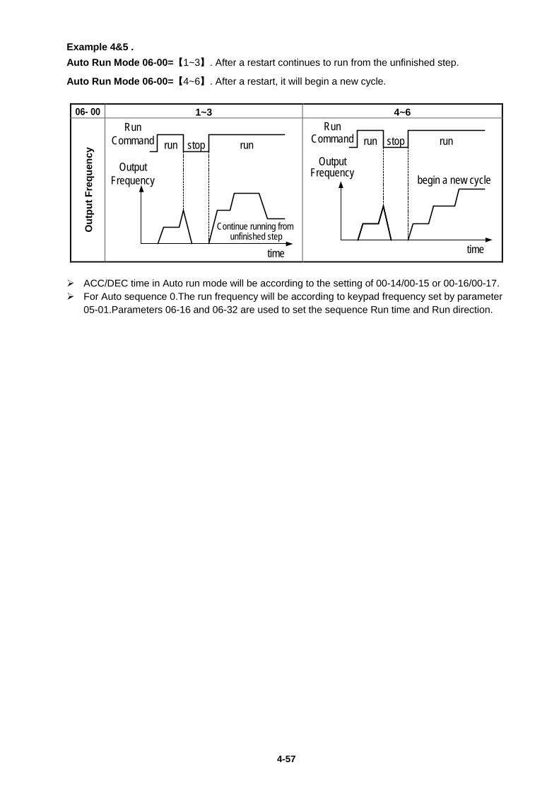
4-57
Example 4&5 . Auto Run Mode 06-00=【1~3】. After a restart continues to run from the unfinished step.
Auto Run Mode 06-00=【4~6】. After a restart, it will begin a new cycle.
06- 00 1~3 4~6
Out
put F
requ
ency
ACC/DEC time in Auto run mode will be according to the setting of 00-14/00-15 or 00-16/00-17. For Auto sequence 0.The run frequency will be according to keypad frequency set by parameter
05-01.Parameters 06-16 and 06-32 are used to set the sequence Run time and Run direction.
time
OutputFrequency
RunCommand
Continue running from unfinished step
stop runrun
time
OutputFrequency
RunCommand
begin a new cycle
stop runrun
4-58
07- Start/Stop command setup 07- 00 Momentary power loss and restart
Range
【0】:Momentary Power Loss and Restart disable
【1】:Momentary power loss and restart enable If the input power supply due to sudden increase in supply demand by other equipment results
in voltage drops below the under voltage level, the inverter will stop its output at once. When 07-00 =【0】.On power loss, the inverter will not start.
When 07-00 =【1】.Aafter a momentary power loss, inverter will restart with the same frequency before power loss, and there is no limitation on number of restarts.
On power loss, as long as the inverter CPU power is not completely lost, the momentary power loss restart will be effective, restart will be according to setting of parameters 00-02 & 07-04 and status of External run switch.
Caution: After any power loss if the Run mode is set to External by parameter 00-02=1 and if Direct start on power up is also selected by parameter 07-04=0, please note that the inverter will run on resumption of power. To ensure safety of operators and to avoid any damages to the machinery, all necessary safety measure must be considered, including disconnection of power to the inverter.
07- 01 Auto Restart Delay Time
Range 【0.0~800.0】s 07- 02 Number of Auto Restart Attempts
Range 【0~10】
07- 02=【0】: The inverter will not auto restart after trips due to fault.
07- 02>【0】, 07- 01=【0】.After a trip due to fault the inverter will run with the same frequency before power loss, and restarts after an internal delay of 0.5 seconds.
07- 02>【0】, 07- 01>【0】, After a fault trip the inverter will run with the same frequency before power loss, and restart with a delay according the preset in parameter 07-01.
Note: Auto restart after a fault will not function while DC injection braking or decelerating to stop
Note: this function is available just after a fault/error. This parameter cannot be used after momentary power loss.
07- 03 Reset Mode Setting
Range 【0】:Enable Reset Only when Run Command is Off
【1】:Enable Reset when Run Command is On or Off 07-03=0 Once the inverter is detected a fault, please turn Run switch Off and then On again to
perform reset, otherwise restarting will not be possible.
07- 04 Direct Running on Power Up
Range 【0】:Enable Direct running after power up
【1】:Disable Direct running after power up 07- 05 Delay-ON Timer (Seconds)
Range 【1.0~300.0】s When direct run on power up is selected by 07-04=0 and the inverter is set to external run by
(00-02/00-03=1), if the run switch is ON as power is applied, the inverter will auto start.
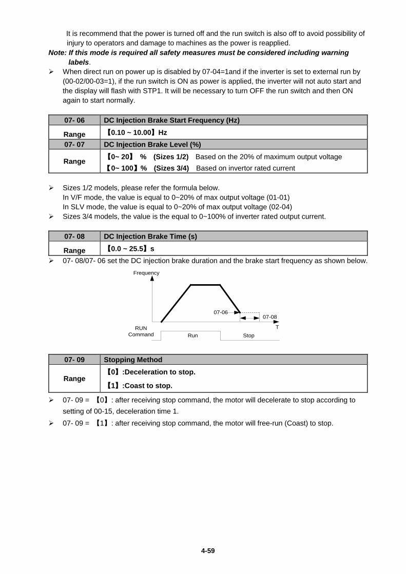
4-59
It is recommend that the power is turned off and the run switch is also off to avoid possibility of injury to operators and damage to machines as the power is reapplied.
Note: If this mode is required all safety measures must be considered including warning labels.
When direct run on power up is disabled by 07-04=1and if the inverter is set to external run by (00-02/00-03=1), if the run switch is ON as power is applied, the inverter will not auto start and the display will flash with STP1. It will be necessary to turn OFF the run switch and then ON again to start normally.
07- 06 DC Injection Brake Start Frequency (Hz)
Range 【0.10 ~ 10.00】Hz 07- 07 DC Injection Brake Level (%)
Range 【0~ 20】 % (Sizes 1/2) Based on the 20% of maximum output voltage 【0~ 100】% (Sizes 3/4) Based on invertor rated current
Sizes 1/2 models, please refer the formula below.
In V/F mode, the value is equal to 0~20% of max output voltage (01-01) In SLV mode, the value is equal to 0~20% of max output voltage (02-04)
Sizes 3/4 models, the value is the equal to 0~100% of inverter rated output current.
07- 08 DC Injection Brake Time (s)
Range 【0.0 ~ 25.5】s 07- 08/07- 06 set the DC injection brake duration and the brake start frequency as shown below.
Frequency
T
07-0807-06
RUN Command Run Stop
07- 09 Stopping Method
Range 【0】:Deceleration to stop.
【1】:Coast to stop.
07- 09 = 【0】: after receiving stop command, the motor will decelerate to stop according to setting of 00-15, deceleration time 1.
07- 09 = 【1】: after receiving stop command, the motor will free-run (Coast) to stop.
4-60
08- Protection function group 08- 00 Trip Prevention Selection
Range
【xxxx0】:Enable Trip Prevention During Acceleration 【xxxx1】:Disable Trip Prevention During Acceleration 【xxx0x】:Enable Trip Prevention During Deceleration 【xxx1x】:Disable Trip Prevention During Deceleration 【xx0xx】:Enable Trip Prevention in Run Mode 【xx1xx】:Disable Trip Prevention in Run Mode 【x0xxx】:Enable over voltage Prevention in Run Mode 【x1xxx】:Disable over voltage Prevention in Run Mode
08- 01 Trip Prevention Level During Acceleration
Range 【50 ~ 200】% Trip prevention adjustment level during acceleration to prevent over current (OC-A) trips. If trip prevention during acceleration is enabled and an over current occurs due to the load, then
the acceleration is interrupted until the over current level is dropped below the setting in 08-01 then the acceleration is resumed.
08- 02 Trip Prevention Level During Deceleration
Range 【50 ~ 200】% Trip prevention adjustment level during deceleration to prevent over Voltage (OV-C) trips. If trip prevention during deceleration is enabled and an over voltage occurs during stopping due
to the load, then the deceleration is interrupted until the over voltage level is dropped below the setting in 08-02 then the deceleration is resumed.
08- 03 Trip Prevention Level during continuous Run Mode
Range 【50 ~ 200】% Trip prevention adjustment level during continuous Run to prevent over current (OC-C) trips. If trip prevention during continuous Run is enabled and an over current occurs due the load
such as a sudden transient load, then the output frequency is reduced by decelerating to a lower speed until the over current level is dropped below the preset in 08-03, then the output frequency accelerates back to the normal running frequency.
08- 04 Over voltage Prevention Level during Run Mode
Range 200:【350~390】VDC 400:【700~780】VDC
Over voltage prevention level can be set by parameter 08-04 when necessary. When the DC bus voltage is higher than 08-04, inverter will keep running, the output frequency will be decreased once the DC bus voltage reduced. It’s the over voltage prevention function, inverter will not appear any error message. (If the DC bus voltage higher than OV protection level, inverter will appear “OV” message). 08- 05 Electronic Motor Overload Protection Operation Mode(OL1)
Range
xxxx0: Disable Electronic Motor Overload Protection xxxx1: Enable Electronic Motor Overload Protection xxx0x: Motor Overload Cold Start xxx1x: Motor Overload Hot Start xx0xx: Standard Motor xx1xx: Invertor Duty Motor ( Force Vent)
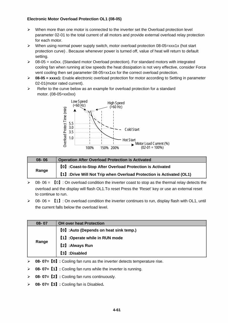
4-61
Electronic Motor Overload Protection OL1 (08-05) When more than one motor is connected to the inverter set the Overload protection level
parameter 02-01 to the total current of all motors and provide external overload relay protection for each motor.
When using normal power supply switch, motor overload protection 08-05=xxx1x (hot start protection curve) . Because whenever power is turned off, value of heat will return to default setting.
08-05 = xx0xx. (Standard motor Overload protection). For standard motors with integrated cooling fan when running at low speeds the heat dissipation is not very effective, consider Force vent cooling then set parameter 08-05=xx1xx for the correct overload protection.
08-05 = xxxx1: Enable electronic overload protection for motor according to Setting in parameter 02-01(motor rated current).
Refer to the curve below as an example for overload protection for a standard motor. (08-05=xx0xx)
Cold Start
Low Speed (<60 Hz)
Hot Start
High Speed (>60 Hz)
100% 150% 200%Motor Load Current (%)
(02-01 = 100%)
5.5
3.5
Over
load P
rotec
t Tim
e (mi
n)
3.0
1.0
08- 06 Operation After Overload Protection is Activated
Range 【0】:Coast-to-Stop After Overload Protection is Activated
【1】:Drive Will Not Trip when Overload Protection is Activated (OL1)
08- 06 = 【0】: On overload condition the inverter coast to stop as the thermal relay detects the overload and the display will flash OL1.To reset Press the ‘Reset’ key or use an external reset to continue to run.
08- 06 = 【1】: On overload condition the inverter continues to run, display flash with OL1, until the current falls below the overload level.
08- 07 OH over heat Protection
Range
【0】:Auto (Depends on heat sink temp.)
【1】:Operate while in RUN mode
【2】:Always Run
【3】:Disabled
08- 07=【0】: Cooling fan runs as the inverter detects temperature rise.
08- 07=【1】: Cooling fan runs while the inverter is running.
08- 07=【2】: Cooling fan runs continuously.
08- 07=【3】: Cooling fan is Disabled.
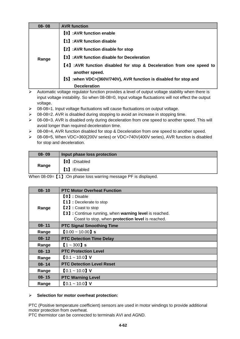
4-62
08- 08 AVR function
Range
【0】:AVR function enable
【1】:AVR function disable
【2】:AVR function disable for stop
【3】:AVR function disable for Deceleration
【4】:AVR function disabled for stop & Deceleration from one speed to another speed.
【5】:when VDC>(360V/740V), AVR function is disabled for stop and Deceleration
Automatic voltage regulator function provides a level of output voltage stability when there is input voltage instability. So when 08-08=0, Input voltage fluctuations will not effect the output voltage.
08-08=1. Input voltage fluctuations will cause fluctuations on output voltage. 08-08=2. AVR is disabled during stopping to avoid an increase in stopping time. 08-08=3. AVR is disabled only during deceleration from one speed to another speed. This will
avoid longer than required deceleration time. 08-08=4, AVR function disabled for stop & Deceleration from one speed to another speed. 08-08=5, When VDC>360(200V series) or VDC>740V(400V series), AVR function is disabled
for stop and deceleration.
08- 09 Input phase loss protection
Range 【0】:Disabled
【1】:Enabled When 08-09=【1】:On phase loss warring message PF is displayed.
08- 10 PTC Motor Overheat Function
Range
【0】: Disable 【1】: Decelerate to stop 【2】: Coast to stop 【3】: Continue running, when warning level is reached. Coast to stop, when protection level is reached.
08- 11 PTC Signal Smoothing Time Range 【0.00 ~ 10.00】s 08- 12 PTC Detection Time Delay Range 【1 ~ 300】s 08- 13 PTC Protection Level Range 【0.1 ~ 10.0】V 08- 14 PTC Detection Level Reset Range 【0.1 ~ 10.0】V 08- 15 PTC Warning Level Range 【0.1 ~ 10.0】V
Selection for motor overheat protection: PTC (Positive temperature coefficient) sensors are used in motor windings to provide additional motor protection from overheat. PTC thermistor can be connected to terminals AVI and AGND.
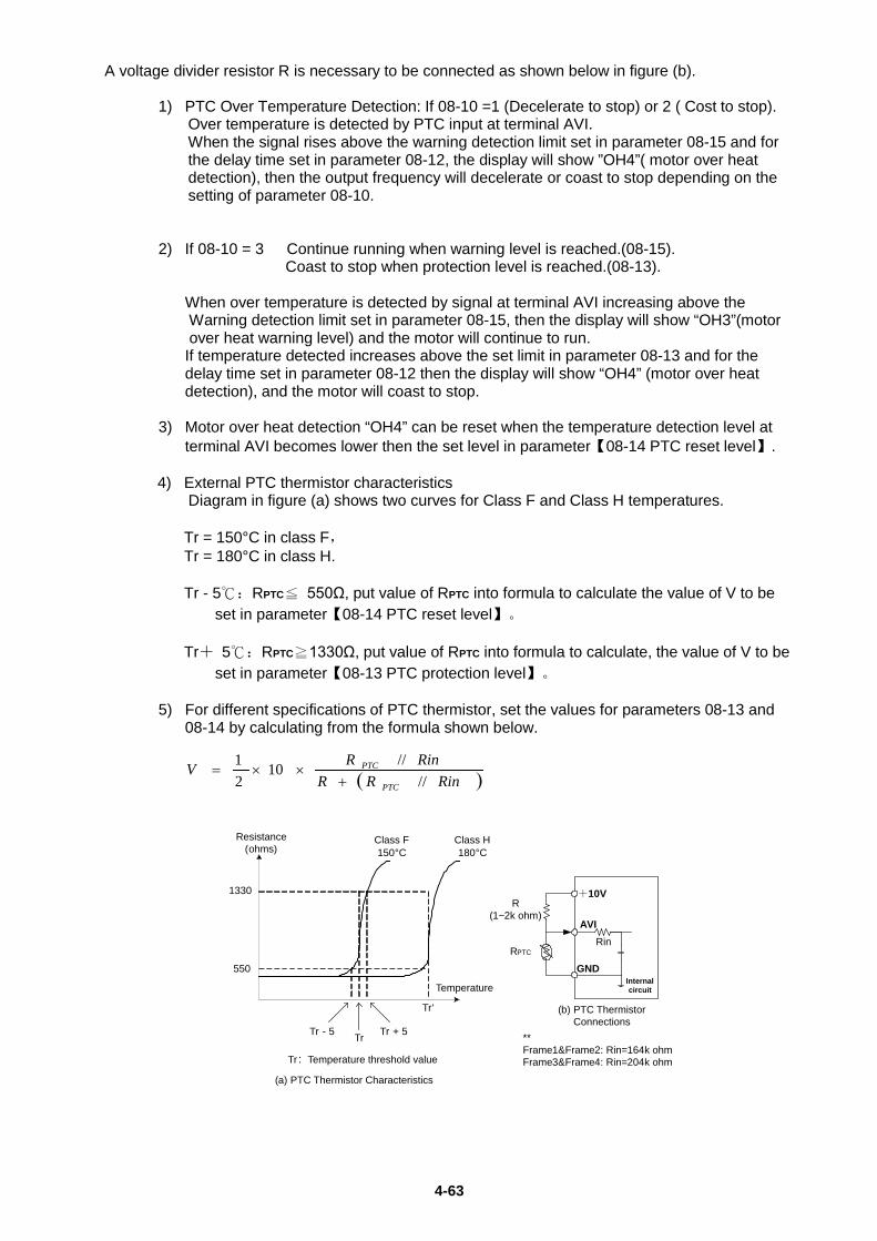
4-63
A voltage divider resistor R is necessary to be connected as shown below in figure (b). 1) PTC Over Temperature Detection: If 08-10 =1 (Decelerate to stop) or 2 ( Cost to stop).
Over temperature is detected by PTC input at terminal AVI. When the signal rises above the warning detection limit set in parameter 08-15 and for the delay time set in parameter 08-12, the display will show ”OH4”( motor over heat detection), then the output frequency will decelerate or coast to stop depending on the setting of parameter 08-10.
2) If 08-10 = 3 Continue running when warning level is reached.(08-15). Coast to stop when protection level is reached.(08-13). When over temperature is detected by signal at terminal AVI increasing above the
Warning detection limit set in parameter 08-15, then the display will show “OH3”(motor over heat warning level) and the motor will continue to run.
If temperature detected increases above the set limit in parameter 08-13 and for the delay time set in parameter 08-12 then the display will show “OH4” (motor over heat detection), and the motor will coast to stop.
3) Motor over heat detection “OH4” can be reset when the temperature detection level at
terminal AVI becomes lower then the set level in parameter【08-14 PTC reset level】.
4) External PTC thermistor characteristics Diagram in figure (a) shows two curves for Class F and Class H temperatures.
Tr = 150°C in class F, Tr = 180°C in class H. Tr - 5℃:RPTC≦ 550Ω, put value of RPTC into formula to calculate the value of V to be
set in parameter【08-14 PTC reset level】。 Tr+ 5℃:RPTC≧1330Ω, put value of RPTC into formula to calculate, the value of V to be
set in parameter【08-13 PTC protection level】。
5) For different specifications of PTC thermistor, set the values for parameters 08-13 and 08-14 by calculating from the formula shown below.
( )RinRRRinRV
PTC
PTC
////10
21
+××=
1330
550
Resistance (ohms)
Temperature
Class F150°C
Class H180°C
Tr'
Tr - 5 Tr Tr + 5
Tr:Temperature threshold value
(a) PTC Thermistor Characteristics
(b) PTC Thermistor Connections
R(1~2k ohm)
RPTC
+10V
AVI
GNDInternal circuit
Rin
**Frame1&Frame2: Rin=164k ohmFrame3&Frame4: Rin=204k ohm
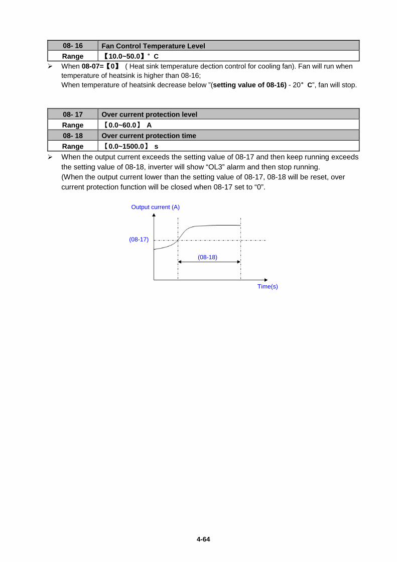
4-64
08- 16 Fan Control Temperature Level Range 【10.0~50.0】°C
When 08-07=【0】 ( Heat sink temperature dection control for cooling fan). Fan will run when temperature of heatsink is higher than 08-16; When temperature of heatsink decrease below ”(setting value of 08-16) - 20°C”, fan will stop.
08- 17 Over current protection level Range 【0.0~60.0】 A 08- 18 Over current protection time Range 【0.0~1500.0】 s
When the output current exceeds the setting value of 08-17 and then keep running exceeds the setting value of 08-18, inverter will show “OL3” alarm and then stop running. (When the output current lower than the setting value of 08-17, 08-18 will be reset, over current protection function will be closed when 08-17 set to “0”.
Output current (A)
Time(s)
(08-18)
(08-17)
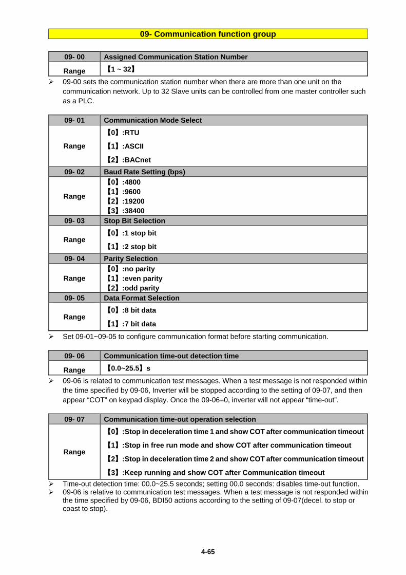
4-65
09- Communication function group
09- 00 Assigned Communication Station Number
Range 【1 ~ 32】 09-00 sets the communication station number when there are more than one unit on the
communication network. Up to 32 Slave units can be controlled from one master controller such as a PLC.
09- 01 Communication Mode Select
Range
【0】:RTU
【1】:ASCII
【2】:BACnet 09- 02 Baud Rate Setting (bps)
Range
【0】:4800 【1】:9600 【2】:19200 【3】:38400
09- 03 Stop Bit Selection
Range 【0】:1 stop bit
【1】:2 stop bit 09- 04 Parity Selection
Range 【0】:no parity 【1】:even parity 【2】:odd parity
09- 05 Data Format Selection
Range 【0】:8 bit data
【1】:7 bit data Set 09-01~09-05 to configure communication format before starting communication.
09- 06 Communication time-out detection time
Range 【0.0~25.5】s 09-06 is related to communication test messages. When a test message is not responded within
the time specified by 09-06, Inverter will be stopped according to the setting of 09-07, and then appear “COT” on keypad display. Once the 09-06=0, inverter will not appear “time-out”.
09- 07 Communication time-out operation selection
Range
【0】:Stop in deceleration time 1 and show COT after communication timeout
【1】:Stop in free run mode and show COT after communication timeout
【2】:Stop in deceleration time 2 and show COT after communication timeout
【3】:Keep running and show COT after Communication timeout Time-out detection time: 00.0~25.5 seconds; setting 00.0 seconds: disables time-out function. 09-06 is relative to communication test messages. When a test message is not responded within
the time specified by 09-06, BDI50 actions according to the setting of 09-07(decel. to stop or coast to stop).
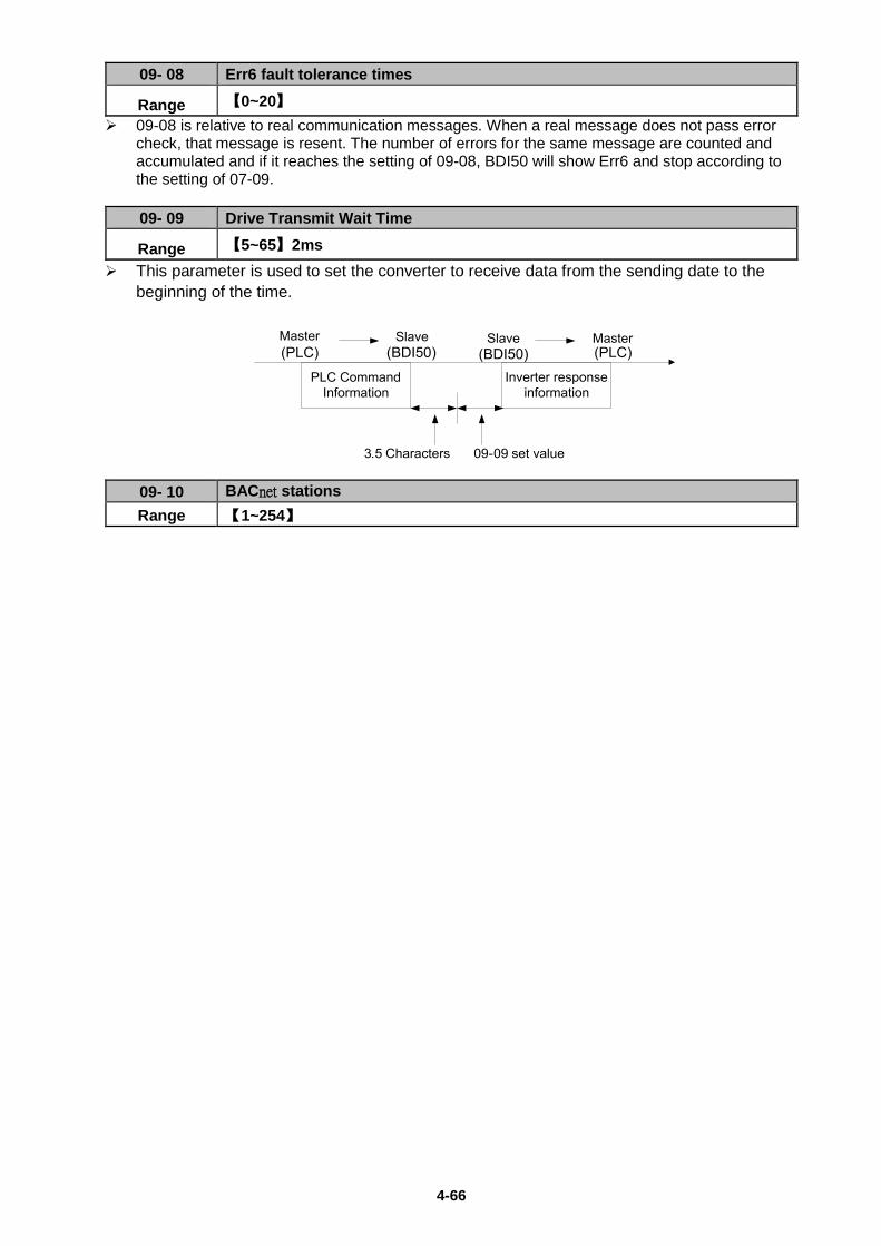
4-66
09- 08 Err6 fault tolerance times
Range 【0~20】 09-08 is relative to real communication messages. When a real message does not pass error
check, that message is resent. The number of errors for the same message are counted and accumulated and if it reaches the setting of 09-08, BDI50 will show Err6 and stop according to the setting of 07-09.
09- 09 Drive Transmit Wait Time
Range 【5~65】2ms This parameter is used to set the converter to receive data from the sending date to the
beginning of the time.
09- 10 BACnet stations Range 【1~254】
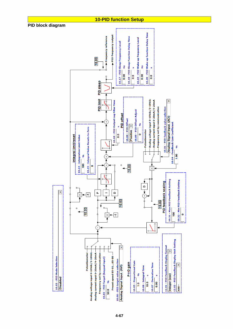
4-67
10-PID function Setup PID block diagram
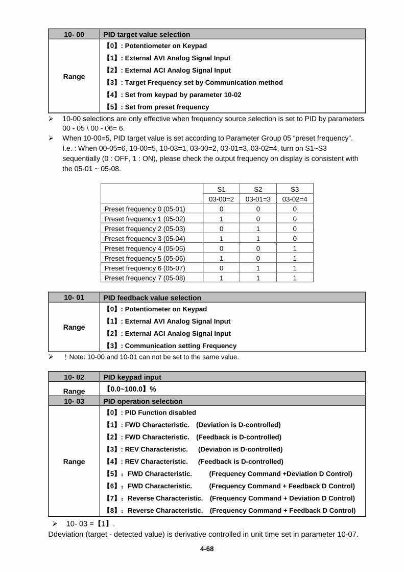
4-68
10- 00 PID target value selection
Range
【0】: Potentiometer on Keypad
【1】: External AVI Analog Signal Input
【2】: External ACI Analog Signal Input
【3】: Target Frequency set by Communication method
【4】: Set from keypad by parameter 10-02
【5】: Set from preset frequency 10-00 selections are only effective when frequency source selection is set to PID by parameters
00 - 05 \ 00 - 06= 6. When 10-00=5, PID target value is set according to Parameter Group 05 “preset frequency”.
I.e. : When 00-05=6, 10-00=5, 10-03=1, 03-00=2, 03-01=3, 03-02=4, turn on S1~S3 sequentially (0 : OFF, 1 : ON), please check the output frequency on display is consistent with the 05-01 ~ 05-08.
S1 S2 S3
03-00=2 03-01=3 03-02=4 Preset frequency 0 (05-01) 0 0 0 Preset frequency 1 (05-02) 1 0 0 Preset frequency 2 (05-03) 0 1 0 Preset frequency 3 (05-04) 1 1 0 Preset frequency 4 (05-05) 0 0 1 Preset frequency 5 (05-06) 1 0 1 Preset frequency 6 (05-07) 0 1 1 Preset frequency 7 (05-08) 1 1 1
10- 01 PID feedback value selection
Range
【0】: Potentiometer on Keypad
【1】: External AVI Analog Signal Input
【2】: External ACI Analog Signal Input
【3】: Communication setting Frequency !Note: 10-00 and 10-01 can not be set to the same value.
10- 02 PID keypad input
Range 【0.0~100.0】% 10- 03 PID operation selection
Range
【0】: PID Function disabled
【1】: FWD Characteristic. (Deviation is D-controlled)
【2】: FWD Characteristic. (Feedback is D-controlled)
【3】: REV Characteristic. (Deviation is D-controlled)
【4】: REV Characteristic. (Feedback is D-controlled)
【5】:FWD Characteristic. (Frequency Command +Deviation D Control)
【6】:FWD Characteristic. (Frequency Command + Feedback D Control)
【7】:Reverse Characteristic. (Frequency Command + Deviation D Control)
【8】:Reverse Characteristic. (Frequency Command + Feedback D Control)
10- 03 =【1】. Ddeviation (target - detected value) is derivative controlled in unit time set in parameter 10-07.
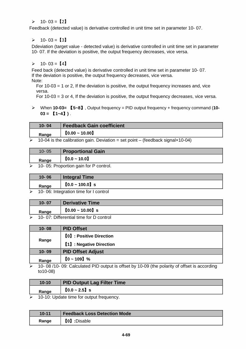
4-69
10- 03 =【2】 Feedback (detected value) is derivative controlled in unit time set in parameter 10- 07. 10- 03 =【3】 Ddeviation (target value - detected value) is derivative controlled in unit time set in parameter 10- 07. If the deviation is positive, the output frequency decreases, vice versa. 10- 03 =【4】 Feed back (detected value) is derivative controlled in unit time set in parameter 10- 07. If the deviation is positive, the output frequency decreases, vice versa. Note:
For 10-03 = 1 or 2, If the deviation is positive, the output frequency increases and, vice versa. For 10-03 = 3 or 4, If the deviation is positive, the output frequency decreases, vice versa.
When 10-03= 【5~8】, Output frequency = PID output frequency + frequency command (10- 03 = 【1~4】) .
10- 04 Feedback Gain coefficient
Range 【0.00 ~ 10.00】 10-04 is the calibration gain. Deviation = set point – (feedback signal×10-04)
10- 05 Proportional Gain
Range 【0.0 ~ 10.0】 10- 05: Proportion gain for P control.
10- 06 Integral Time
Range 【0.0 ~ 100.0】s 10- 06: Integration time for I control
10- 07 Derivative Time
Range 【0.00 ~ 10.00】s 10- 07: Differential time for D control
10- 08 PID Offset
Range 【0】: Positive Direction
【1】: Negative Direction 10- 09 PID Offset Adjust
Range 【0 ~ 109】% 10- 08 /10- 09: Calculated PID output is offset by 10-09 (the polarity of offset is according
to10-08)
10-10 PID Output Lag Filter Time
Range 【0.0 ~ 2.5】s 10-10: Update time for output frequency.
10-11 Feedback Loss Detection Mode Range 【0】:Disable
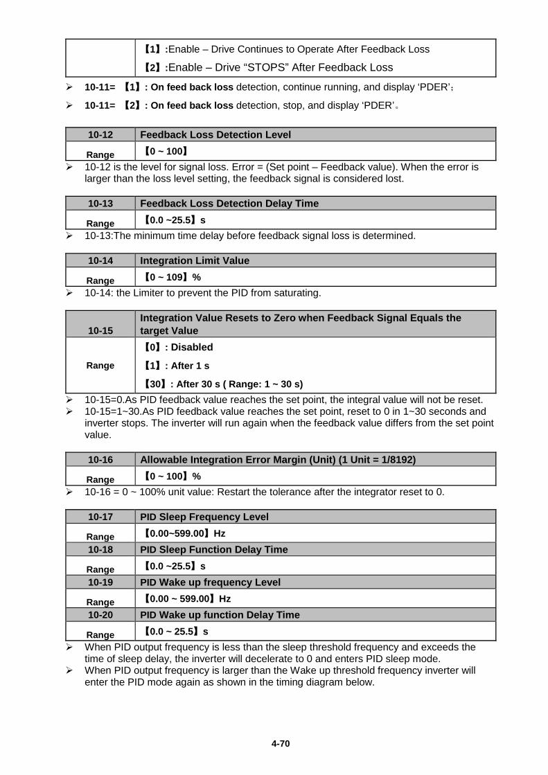
4-70
【1】:Enable – Drive Continues to Operate After Feedback Loss
【2】:Enable – Drive “STOPS” After Feedback Loss
10-11= 【1】: On feed back loss detection, continue running, and display ‘PDER’;
10-11= 【2】: On feed back loss detection, stop, and display ‘PDER’。
10-12 Feedback Loss Detection Level
Range 【0 ~ 100】 10-12 is the level for signal loss. Error = (Set point – Feedback value). When the error is
larger than the loss level setting, the feedback signal is considered lost.
10-13 Feedback Loss Detection Delay Time
Range 【0.0 ~25.5】s 10-13:The minimum time delay before feedback signal loss is determined.
10-14 Integration Limit Value
Range 【0 ~ 109】% 10-14: the Limiter to prevent the PID from saturating.
10-15 Integration Value Resets to Zero when Feedback Signal Equals the target Value
Range
【0】: Disabled
【1】: After 1 s
【30】: After 30 s ( Range: 1 ~ 30 s) 10-15=0.As PID feedback value reaches the set point, the integral value will not be reset. 10-15=1~30.As PID feedback value reaches the set point, reset to 0 in 1~30 seconds and
inverter stops. The inverter will run again when the feedback value differs from the set point value.
10-16 Allowable Integration Error Margin (Unit) (1 Unit = 1/8192)
Range 【0 ~ 100】% 10-16 = 0 ~ 100% unit value: Restart the tolerance after the integrator reset to 0.
10-17 PID Sleep Frequency Level
Range 【0.00~599.00】Hz 10-18 PID Sleep Function Delay Time
Range 【0.0 ~25.5】s 10-19 PID Wake up frequency Level
Range 【0.00 ~ 599.00】Hz 10-20 PID Wake up function Delay Time
Range 【0.0 ~ 25.5】s When PID output frequency is less than the sleep threshold frequency and exceeds the
time of sleep delay, the inverter will decelerate to 0 and enters PID sleep mode. When PID output frequency is larger than the Wake up threshold frequency inverter will
enter the PID mode again as shown in the timing diagram below.
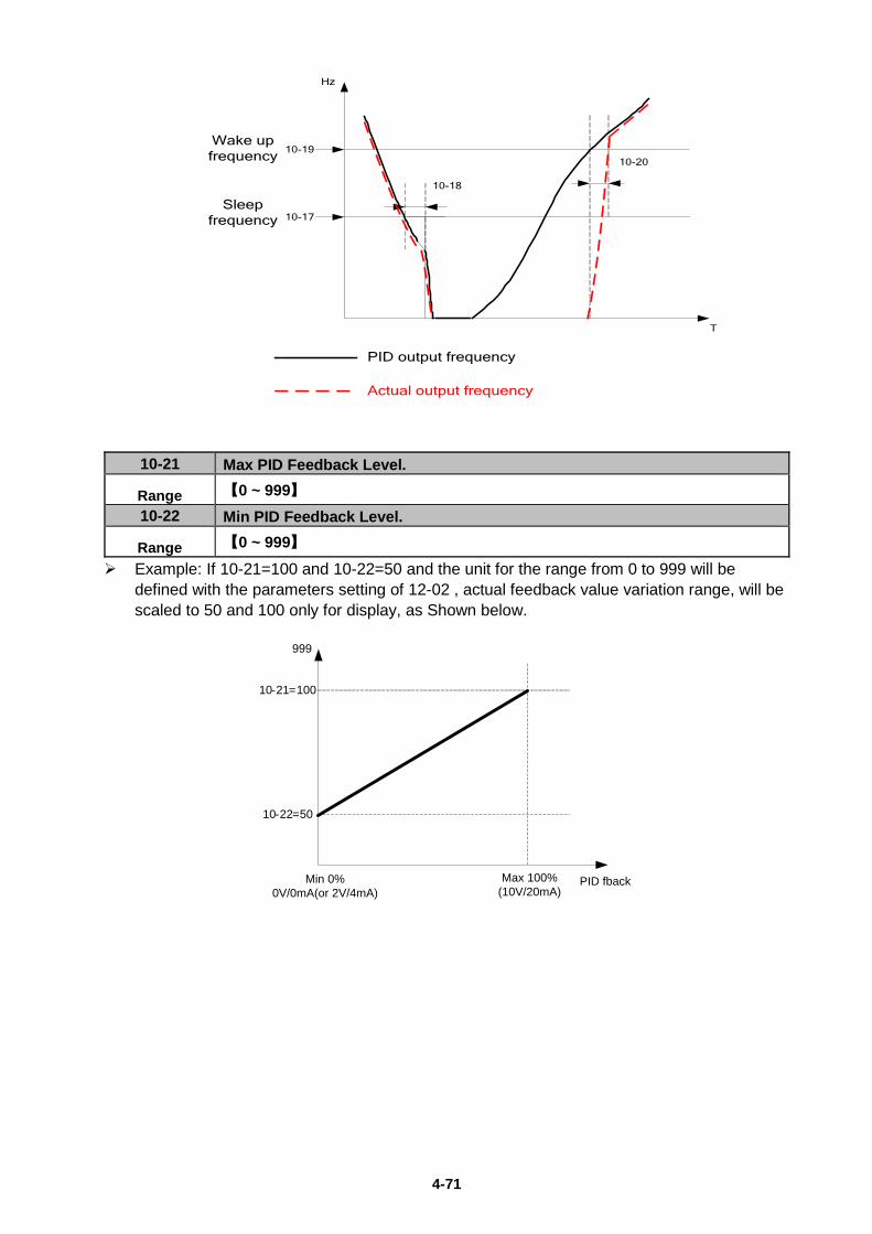
4-71
10-18
Hz
T
10-19
10-17
10-20
Wake upfrequency
Sleepfrequency
PID output frequency
Actual output frequency
10-21 Max PID Feedback Level.
Range 【0 ~ 999】 10-22 Min PID Feedback Level.
Range 【0 ~ 999】 Example: If 10-21=100 and 10-22=50 and the unit for the range from 0 to 999 will be
defined with the parameters setting of 12-02 , actual feedback value variation range, will be scaled to 50 and 100 only for display, as Shown below.
10-21=100
10-22=50
Min 0%0V/0mA(or 2V/4mA)
Max 100%(10V/20mA)
999
PID fback
4-72
11 Performance control functions
11- 00 Prevention of Reverse operation
Range 【0】:Reverse command is enabled
【1】:Reverse command is disabled 11-00=1, the reverse command is disabled.
11- 01 Carrier Frequency
Range 【1~16】KHz
11- 02 Carrier mode selection
Range
【0】: Mode 0 3-phase PWM modulation
【1】: Mode 1 2-phase PWM modulation
【2】: Mode 2 random PWM modulation The function can be used for audible noise reduction from a motor. It can be used in cases where the 100% torque from motor is not critical but it is necessary to reduce the audible noise. Mode 0: 3-phase PWM Modulation. Three Output transistors are ON at the same time (Full
Duty). Carrier frequency is set according to Parameter 11-01.
Mode 1: 2-phase PWM Modulation. Two output transistors are ON at the same time (2/3 Duty). This mode is suitable for variable torque applications such as Fan & pump. It reduces the Output transistor switching losses. Carrier frequency will be according to parameter 11-01 with the exception noted below: Note: If 11-01 > 2KHz, 11-03=0 (Auto carrier frequency change is disabled) and the following conditions apply then 2-phase PWM will automatically change to 3- phase PWM with the carrier frequency = 2/3* (11-01). Conditions: • During Acceleration If Output frequency is < 0.7*Fmax. • During Deceleration when output frequency is < 0.6*Fmax • Fmax = (Par 01-02) in Control mode (Par 00-00) = (0) V/f mode • Fmax = (Par 02-06) in Control mode (Par 00-00) = (1) SLV mode
Mode 2: Random PWM Modulation This modulation method will use 3-phase PWM and 2-phase PWM modulation in a random combination. Carrier frequency is set according to Parameter 11-01.
PWM mode selection considerations:
Modes Name IGBT Duty Heat Losses
Torque Performance
Waveform Distortion
Motor Noise
0 3-Phase PWM 100% High High Low Low 1 2-Phase PWM 66.6% Low Low High High 2 Random PWM 66.6% Low Low High Mid
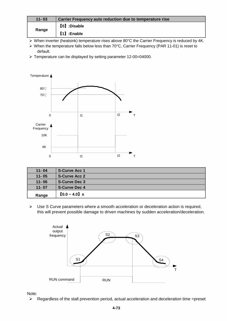
4-73
11- 03 Carrier Frequency auto reduction due to temperature rise
Range 【0】:Disable
【1】:Enable When inverter (heatsink) temperature rises above 80°C the Carrier Frequency is reduced by 4K. When the temperature falls below less than 70°C, Carrier Frequency (PAR 11-01) is reset to
default. Temperature can be displayed by setting parameter 12-00=04000.
70℃
80℃
t1 t2 T0
Temperature
Carrier Frequency
10K
4K
t1 t2 T0
11- 04 S-Curve Acc 1 11- 05 S-Curve Acc 2 11- 06 S-Curve Dec 3 11- 07 S-Curve Dec 4
Range 【0.0 ~ 4.0】s Use S Curve parameters where a smooth acceleration or deceleration action is required,
this will prevent possible damage to driven machines by sudden acceleration/deceleration.
S1
S2 S3
S4
RUN command
Actual output
frequency
RUN
T
Note: Regardless of the stall prevention period, actual acceleration and deceleration time =preset
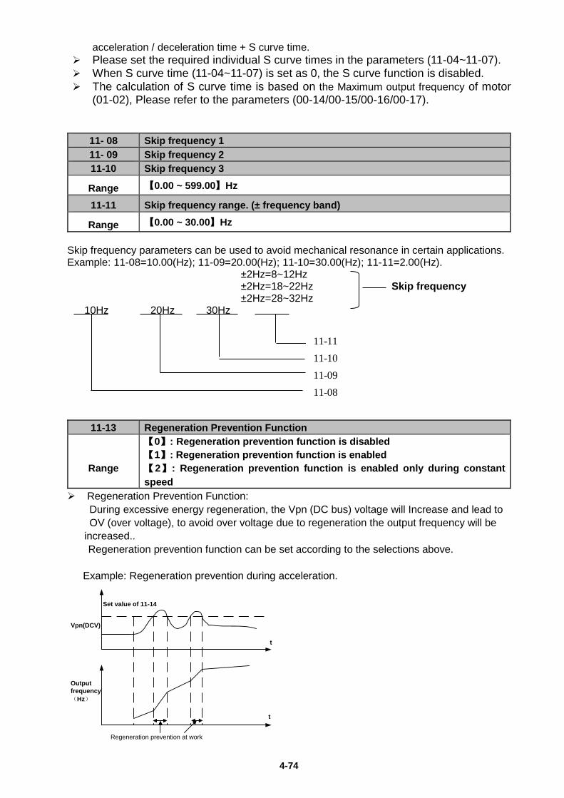
4-74
acceleration / deceleration time + S curve time. Please set the required individual S curve times in the parameters (11-04~11-07). When S curve time (11-04~11-07) is set as 0, the S curve function is disabled. The calculation of S curve time is based on the Maximum output frequency of motor
(01-02), Please refer to the parameters (00-14/00-15/00-16/00-17).
11- 08 Skip frequency 1 11- 09 Skip frequency 2 11-10 Skip frequency 3
Range 【0.00 ~ 599.00】Hz
11-11 Skip frequency range. (± frequency band)
Range 【0.00 ~ 30.00】Hz Skip frequency parameters can be used to avoid mechanical resonance in certain applications. Example: 11-08=10.00(Hz); 11-09=20.00(Hz); 11-10=30.00(Hz); 11-11=2.00(Hz).
±2Hz=8~12Hz ±2Hz=18~22Hz Skip frequency ±2Hz=28~32Hz 10Hz 20Hz 30Hz
11-13 Regeneration Prevention Function
Range
【0】: Regeneration prevention function is disabled 【1】: Regeneration prevention function is enabled 【2】: Regeneration prevention function is enabled only during constant speed
Regeneration Prevention Function: During excessive energy regeneration, the Vpn (DC bus) voltage will Increase and lead to OV (over voltage), to avoid over voltage due to regeneration the output frequency will be
increased.. Regeneration prevention function can be set according to the selections above. Example: Regeneration prevention during acceleration.
Regeneration prevention at work
Vpn(DCV)
Set value of 11-14
Output frequency(Hz)
t
t
11-11 11-10 11-09 11-08
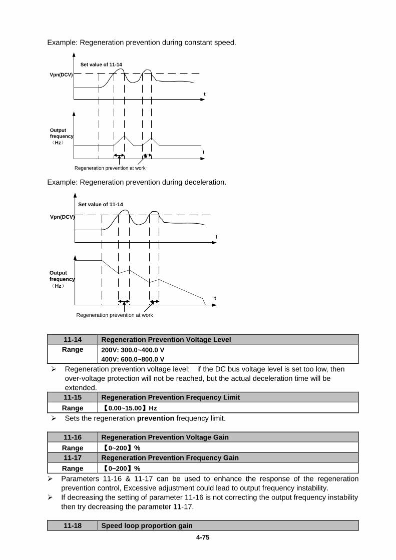
4-75
Example: Regeneration prevention during constant speed.
Set value of 11-14
t
t
Regeneration prevention at work
Vpn(DCV)
Output frequency(Hz)
Example: Regeneration prevention during deceleration.
t
t
Vpn(DCV)
Output frequency(Hz)
Set value of 11-14
Regeneration prevention at work
11-14 Regeneration Prevention Voltage Level Range 200V: 300.0~400.0 V
400V: 600.0~800.0 V Regeneration prevention voltage level: if the DC bus voltage level is set too low, then
over-voltage protection will not be reached, but the actual deceleration time will be extended. 11-15 Regeneration Prevention Frequency Limit Range 【0.00~15.00】Hz
Sets the regeneration prevention frequency limit.
11-16 Regeneration Prevention Voltage Gain Range 【0~200】% 11-17 Regeneration Prevention Frequency Gain Range 【0~200】%
Parameters 11-16 & 11-17 can be used to enhance the response of the regeneration prevention control, Excessive adjustment could lead to output frequency instability.
If decreasing the setting of parameter 11-16 is not correcting the output frequency instability then try decreasing the parameter 11-17. 11-18 Speed loop proportion gain
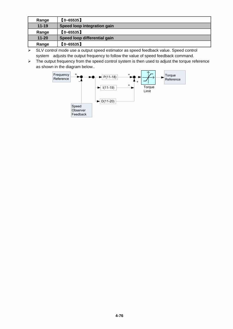
4-76
Range 【0~65535】 11-19 Speed loop integration gain Range 【0~65535】 11-20 Speed loop differential gain Range 【0~65535】
SLV control mode use a output speed estimator as speed feedback value. Speed control system adjusts the output frequency to follow the value of speed feedback command.
The output frequency from the speed control system is then used to adjust the torque reference as shown in the diagram below..
P(11-18)
I(11-19)
+
-
Frequency Reference
Speed Observer Feedback
D(11-20)
+
++
TorqueReference
TorqueLimit
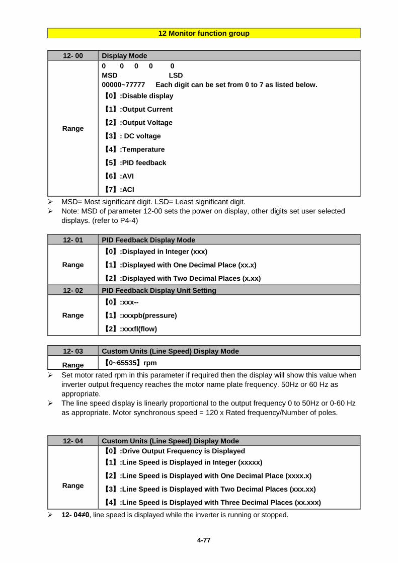
4-77
12 Monitor function group
12- 00 Display Mode
Range
0 0 0 0 0 MSD LSD 00000~77777 Each digit can be set from 0 to 7 as listed below. 【0】:Disable display
【1】:Output Current
【2】:Output Voltage
【3】: DC voltage
【4】:Temperature
【5】:PID feedback
【6】:AVI
【7】:ACI MSD= Most significant digit. LSD= Least significant digit. Note: MSD of parameter 12-00 sets the power on display, other digits set user selected
displays. (refer to P4-4)
12- 01 PID Feedback Display Mode
Range
【0】:Displayed in Integer (xxx)
【1】:Displayed with One Decimal Place (xx.x)
【2】:Displayed with Two Decimal Places (x.xx) 12- 02 PID Feedback Display Unit Setting
Range
【0】:xxx--
【1】:xxxpb(pressure)
【2】:xxxfl(flow)
12- 03 Custom Units (Line Speed) Display Mode
Range 【0~65535】rpm Set motor rated rpm in this parameter if required then the display will show this value when
inverter output frequency reaches the motor name plate frequency. 50Hz or 60 Hz as appropriate.
The line speed display is linearly proportional to the output frequency 0 to 50Hz or 0-60 Hz as appropriate. Motor synchronous speed = 120 x Rated frequency/Number of poles.
12- 04 Custom Units (Line Speed) Display Mode
Range
【0】:Drive Output Frequency is Displayed 【1】:Line Speed is Displayed in Integer (xxxxx)
【2】:Line Speed is Displayed with One Decimal Place (xxxx.x)
【3】:Line Speed is Displayed with Two Decimal Places (xxx.xx)
【4】:Line Speed is Displayed with Three Decimal Places (xx.xxx) 12- 04≠0, line speed is displayed while the inverter is running or stopped.
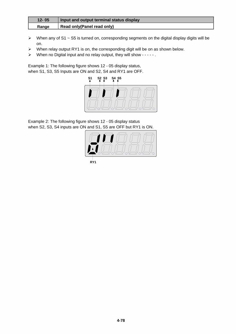
4-78
12- 05 Input and output terminal status display Range Read only(Panel read only)
When any of S1 ~ S5 is turned on, corresponding segments on the digital display digits will be
on. When relay output RY1 is on, the corresponding digit will be on as shown below. When no Digital input and no relay output, they will show - - - - - . Example 1: The following figure shows 12 - 05 display status, when S1, S3, S5 Inputs are ON and S2, S4 and RY1 are OFF.
S1 S2 S3 S4 S5
Example 2: The following figure shows 12 - 05 display status when S2, S3, S4 inputs are ON and S1, S5 are OFF but RY1 is ON.
RY1
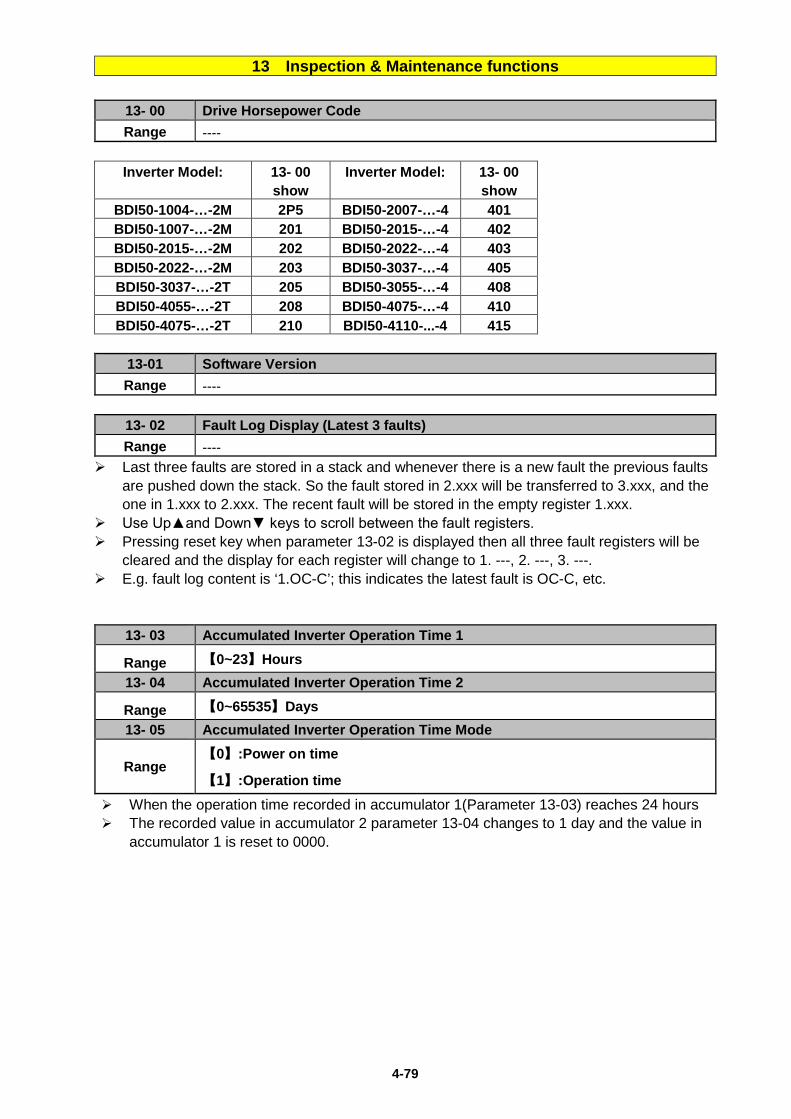
4-79
13 Inspection & Maintenance functions
13- 00 Drive Horsepower Code Range ----
Inverter Model: 13- 00
show Inverter Model: 13- 00
show BDI50-1004-…-2M 2P5 BDI50-2007-…-4 401 BDI50-1007-…-2M 201 BDI50-2015-…-4 402 BDI50-2015-…-2M 202 BDI50-2022-…-4 403 BDI50-2022-…-2M 203 BDI50-3037-…-4 405 BDI50-3037-…-2T 205 BDI50-3055-…-4 408 BDI50-4055-…-2T 208 BDI50-4075-…-4 410 BDI50-4075-…-2T 210 BDI50-4110-...-4 415
13-01 Software Version Range ----
13- 02 Fault Log Display (Latest 3 faults) Range ----
Last three faults are stored in a stack and whenever there is a new fault the previous faults are pushed down the stack. So the fault stored in 2.xxx will be transferred to 3.xxx, and the one in 1.xxx to 2.xxx. The recent fault will be stored in the empty register 1.xxx.
Use Up▲and Down▼ keys to scroll between the fault registers. Pressing reset key when parameter 13-02 is displayed then all three fault registers will be
cleared and the display for each register will change to 1. ---, 2. ---, 3. ---. E.g. fault log content is ‘1.OC-C’; this indicates the latest fault is OC-C, etc.
13- 03 Accumulated Inverter Operation Time 1
Range 【0~23】Hours 13- 04 Accumulated Inverter Operation Time 2
Range 【0~65535】Days 13- 05 Accumulated Inverter Operation Time Mode
Range 【0】:Power on time
【1】:Operation time When the operation time recorded in accumulator 1(Parameter 13-03) reaches 24 hours The recorded value in accumulator 2 parameter 13-04 changes to 1 day and the value in
accumulator 1 is reset to 0000.
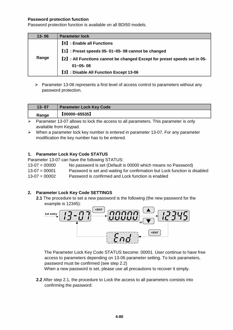
4-80
Password protection function Password protection function is available on all BDI50 models.
13- 06 Parameter lock
Range
【0】: Enable all Functions
【1】: Preset speeds 05- 01~05- 08 cannot be changed
【2】: All Functions cannot be changed Except for preset speeds set in 05- 01~05- 08
【3】: Disable All Function Except 13-06 Parameter 13-06 represents a first level of access control to parameters without any
password protection.
13- 07 Parameter Lock Key Code
Range 【00000~65535】 Parameter 13-07 allows to lock the access to all parameters. This parameter is only
available from Keypad. When a parameter lock key number is entered in parameter 13-07. For any parameter
modification the key number has to be entered. 1. Parameter Lock Key Code STATUS Parameter 13-07 can have the following STATUS: 13-07 = 00000 No password is set (Default is 00000 which means no Password) 13-07 = 00001 Password is set and waiting for confirmation but Lock function is disabled 13-07 = 00002 Password is confirmed and Lock function is enabled 2. Parameter Lock Key Code SETTINGS
2.1 The procedure to set a new password is the following (the new password for the example is 12345):
1st entry▲
▼or
</ENT
</ENT
The Parameter Lock Key Code STATUS become: 00001. User continue to have free access to parameters depending on 13-06 parameter setting. To lock parameters, password must be confirmed (see step 2.2) When a new password is set, please use all precautions to recover it simply.
2.2 After step 2.1, the procedure to Lock the access to all parameters consists into
confirming the password:
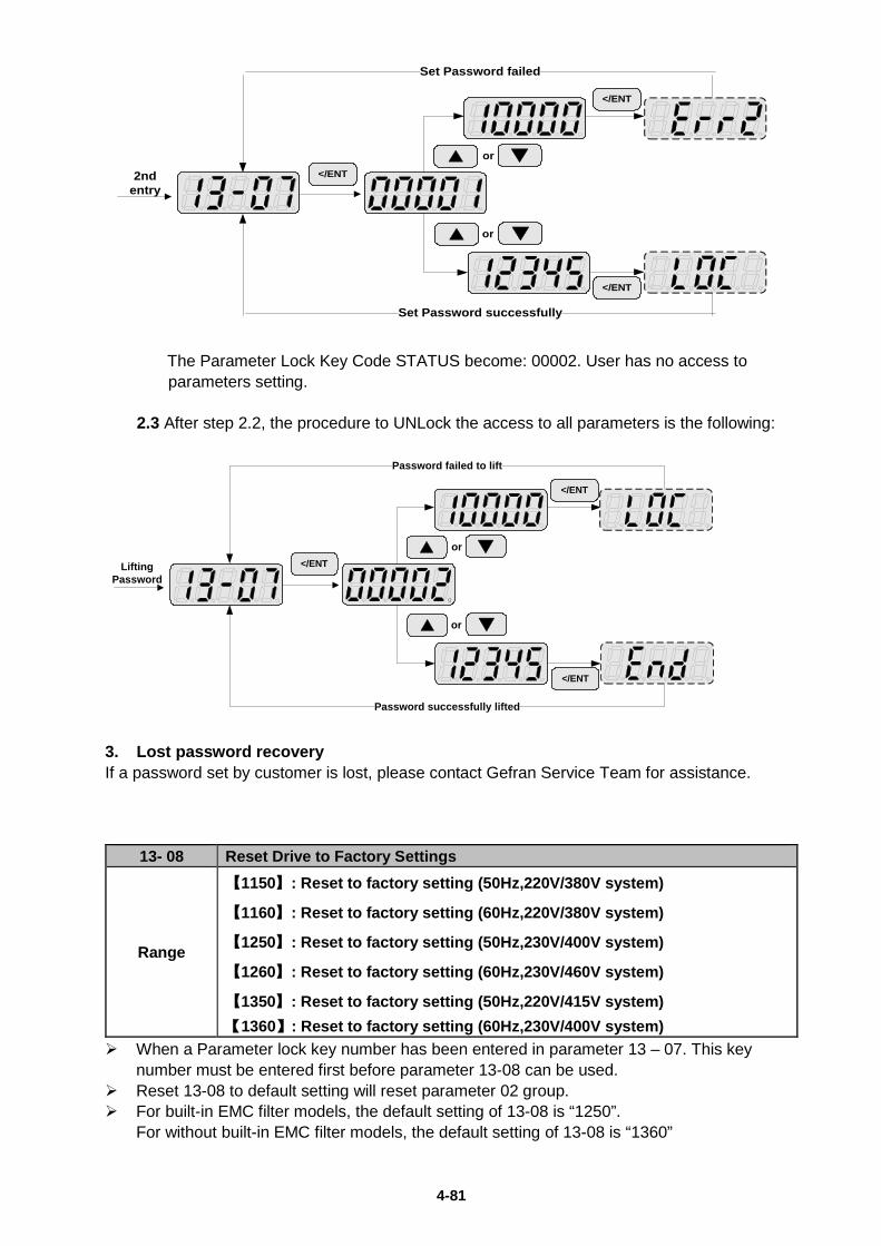
4-81
2nd entry
</ENT
▲ ▼or
</ENT
Set Password successfully
Set Password failed
▲ ▼or
</ENT
The Parameter Lock Key Code STATUS become: 00002. User has no access to parameters setting.
2.3 After step 2.2, the procedure to UNLock the access to all parameters is the following:
Lifting Password
</ENT▲ ▼or
</ENT
Password successfully lifted
Password failed to lift
▲ ▼or
</ENT
3. Lost password recovery If a password set by customer is lost, please contact Gefran Service Team for assistance.
13- 08 Reset Drive to Factory Settings
Range
【1150】: Reset to factory setting (50Hz,220V/380V system)
【1160】: Reset to factory setting (60Hz,220V/380V system)
【1250】: Reset to factory setting (50Hz,230V/400V system)
【1260】: Reset to factory setting (60Hz,230V/460V system)
【1350】: Reset to factory setting (50Hz,220V/415V system) 【1360】: Reset to factory setting (60Hz,230V/400V system)
When a Parameter lock key number has been entered in parameter 13 – 07. This key number must be entered first before parameter 13-08 can be used.
Reset 13-08 to default setting will reset parameter 02 group. For built-in EMC filter models, the default setting of 13-08 is “1250”.
For without built-in EMC filter models, the default setting of 13-08 is “1360”
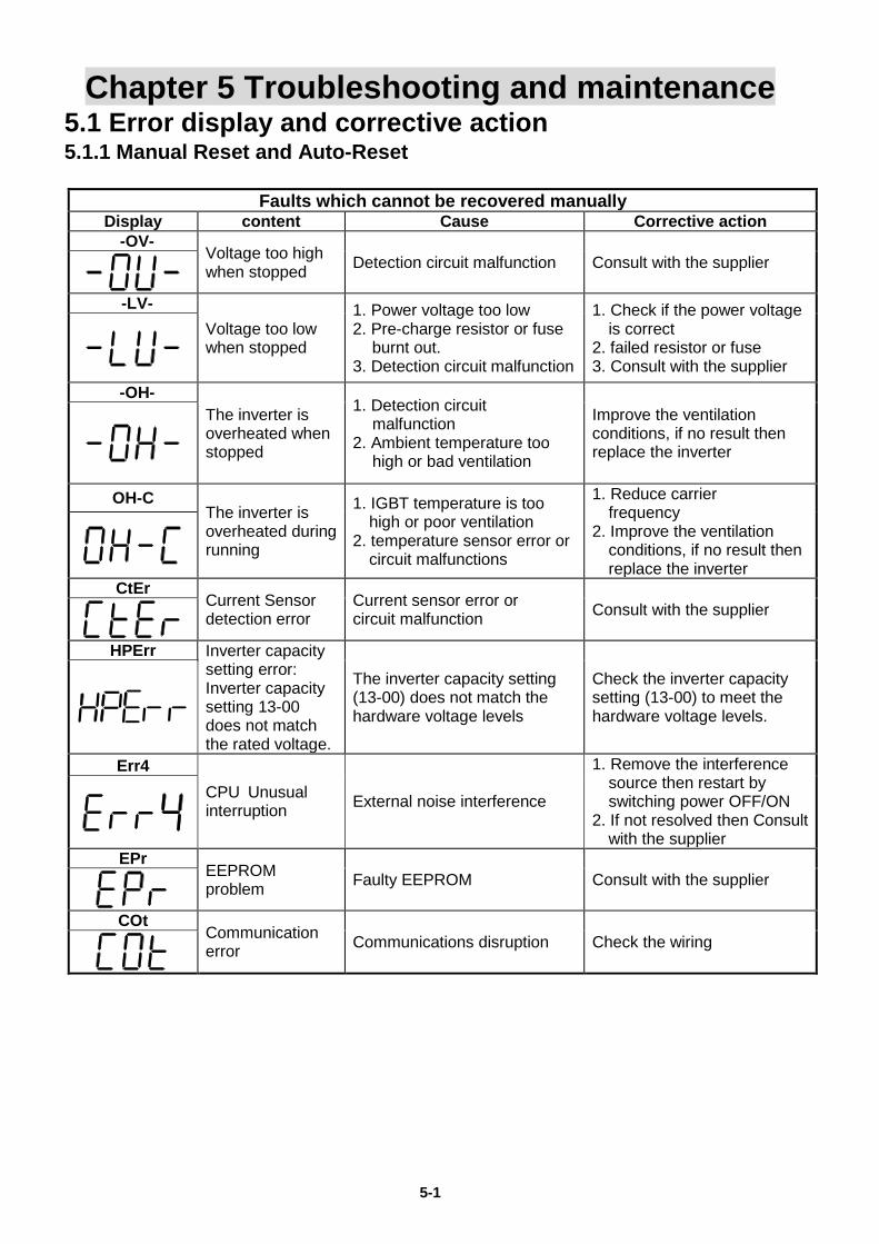
5-1
Chapter 5 Troubleshooting and maintenance 5.1 Error display and corrective action 5.1.1 Manual Reset and Auto-Reset
Faults which cannot be recovered manually Display content Cause Corrective action -OV-
Voltage too high when stopped Detection circuit malfunction Consult with the supplier
-LV-
Voltage too low when stopped
1. Power voltage too low 2. Pre-charge resistor or fuse
burnt out. 3. Detection circuit malfunction
1. Check if the power voltage is correct
2. failed resistor or fuse 3. Consult with the supplier
-OH- The inverter is overheated when stopped
1. Detection circuit malfunction
2. Ambient temperature too high or bad ventilation
Improve the ventilation conditions, if no result then replace the inverter
OH-C The inverter is overheated during running
1. IGBT temperature is too high or poor ventilation
2. temperature sensor error or circuit malfunctions
1. Reduce carrier frequency
2. Improve the ventilation conditions, if no result then replace the inverter
CtEr Current Sensor detection error
Current sensor error or circuit malfunction Consult with the supplier
HPErr Inverter capacity
setting error: Inverter capacity setting 13-00 does not match the rated voltage.
The inverter capacity setting (13-00) does not match the hardware voltage levels
Check the inverter capacity setting (13-00) to meet the hardware voltage levels.
Err4 CPU Unusual interruption External noise interference
1. Remove the interference source then restart by switching power OFF/ON
2. If not resolved then Consult with the supplier
EPr EEPROM problem Faulty EEPROM Consult with the supplier
COt
Communication error Communications disruption Check the wiring
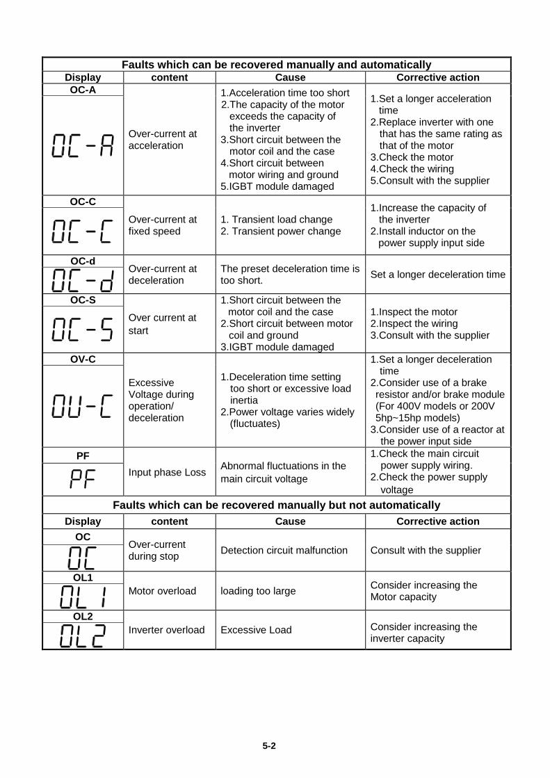
5-2
Faults which can be recovered manually and automatically Display content Cause Corrective action OC-A
Over-current at acceleration
1.Acceleration time too short 2.The capacity of the motor
exceeds the capacity of the inverter
3.Short circuit between the motor coil and the case
4.Short circuit between motor wiring and ground
5.IGBT module damaged
1.Set a longer acceleration time
2.Replace inverter with one that has the same rating as that of the motor
3.Check the motor 4.Check the wiring 5.Consult with the supplier
OC-C Over-current at fixed speed
1. Transient load change 2. Transient power change
1.Increase the capacity of the inverter
2.Install inductor on the power supply input side
OC-d Over-current at deceleration
The preset deceleration time is too short. Set a longer deceleration time
OC-S
Over current at start
1.Short circuit between the motor coil and the case
2.Short circuit between motor coil and ground
3.IGBT module damaged
1.Inspect the motor 2.Inspect the wiring 3.Consult with the supplier
OV-C
Excessive Voltage during operation/ deceleration
1.Deceleration time setting too short or excessive load inertia
2.Power voltage varies widely (fluctuates)
1.Set a longer deceleration time
2.Consider use of a brake resistor and/or brake module (For 400V models or 200V 5hp~15hp models)
3.Consider use of a reactor at the power input side
PF Input phase Loss Abnormal fluctuations in the
main circuit voltage
1.Check the main circuit power supply wiring. 2.Check the power supply voltage
Faults which can be recovered manually but not automatically Display content Cause Corrective action
OC Over-current during stop Detection circuit malfunction Consult with the supplier
OL1
Motor overload loading too large Consider increasing the Motor capacity
OL2
Inverter overload Excessive Load Consider increasing the inverter capacity
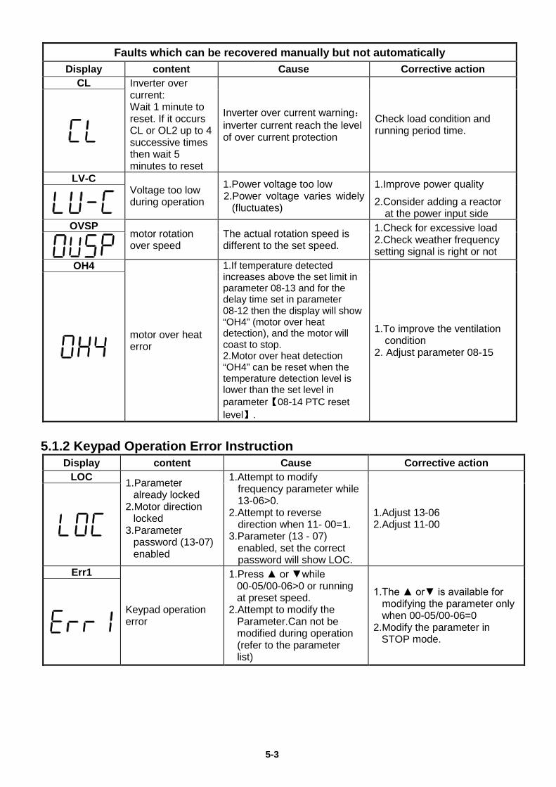
5-3
Faults which can be recovered manually but not automatically Display content Cause Corrective action
CL Inverter over current: Wait 1 minute to reset. If it occurs CL or OL2 up to 4 successive times then wait 5 minutes to reset
Inverter over current warning: inverter current reach the level of over current protection
Check load condition and running period time.
LV-C Voltage too low during operation
1.Power voltage too low 2.Power voltage varies widely
(fluctuates)
1.Improve power quality
2.Consider adding a reactor at the power input side
OVSP motor rotation over speed
The actual rotation speed is different to the set speed.
1.Check for excessive load 2.Check weather frequency setting signal is right or not
OH4
motor over heat error
1.If temperature detected increases above the set limit in parameter 08-13 and for the delay time set in parameter 08-12 then the display will show “OH4” (motor over heat detection), and the motor will coast to stop. 2.Motor over heat detection “OH4” can be reset when the temperature detection level is lower than the set level in parameter【08-14 PTC reset level】.
1.To improve the ventilation condition
2. Adjust parameter 08-15
5.1.2 Keypad Operation Error Instruction Display content Cause Corrective action
LOC 1.Parameter already locked
2.Motor direction locked
3.Parameter password (13-07) enabled
1.Attempt to modify frequency parameter while 13-06>0.
2.Attempt to reverse direction when 11- 00=1.
3.Parameter (13 - 07) enabled, set the correct password will show LOC.
1.Adjust 13-06 2.Adjust 11-00
Err1
Keypad operation error
1.Press ▲ or ▼while 00-05/00-06>0 or running at preset speed.
2.Attempt to modify the Parameter.Can not be modified during operation (refer to the parameter list)
1.The ▲ or▼ is available for modifying the parameter only when 00-05/00-06=0
2.Modify the parameter in STOP mode.
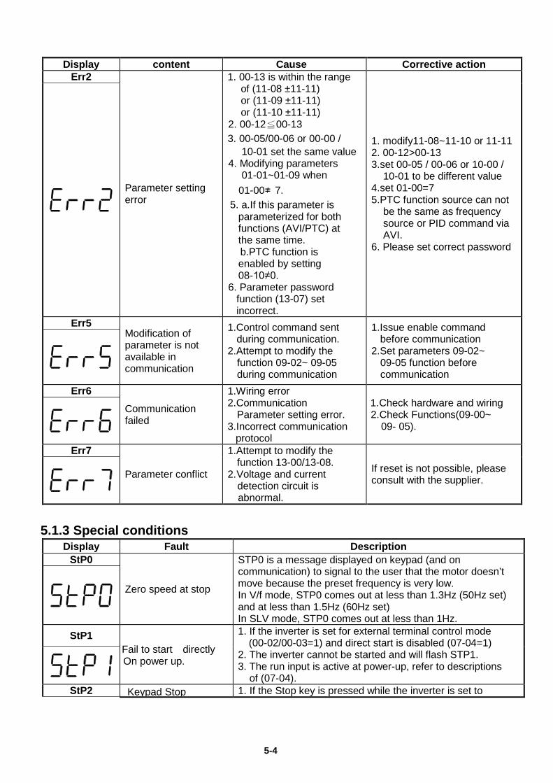
5-4
Display content Cause Corrective action Err2
Parameter setting error
1. 00-13 is within the range of (11-08 ±11-11) or (11-09 ±11-11) or (11-10 ±11-11)
2. 00-12≦00-13 3. 00-05/00-06 or 00-00 /
10-01 set the same value 4. Modifying parameters
01-01~01-09 when 01-00≠ 7. 5. a.If this parameter is
parameterized for both functions (AVI/PTC) at the same time.
b.PTC function is enabled by setting 08-10≠0.
6. Parameter password function (13-07) set incorrect.
1. modify11-08~11-10 or 11-11 2. 00-12>00-13 3.set 00-05 / 00-06 or 10-00 /
10-01 to be different value 4.set 01-00=7 5.PTC function source can not
be the same as frequency source or PID command via AVI.
6. Please set correct password
Err5 Modification of parameter is not available in communication
1.Control command sent during communication.
2.Attempt to modify the function 09-02~ 09-05 during communication
1.Issue enable command before communication
2.Set parameters 09-02~ 09-05 function before communication
Err6 Communication failed
1.Wiring error 2.Communication
Parameter setting error. 3.Incorrect communication
protocol
1. Check hardware and wiring 2.Check Functions(09-00~
09- 05).
Err7
Parameter conflict
1.Attempt to modify the function 13-00/13-08.
2. Voltage and current detection circuit is abnormal.
If reset is not possible, please consult with the supplier.
5.1.3 Special conditions
Display Fault Description StP0
Zero speed at stop
STP0 is a message displayed on keypad (and on communication) to signal to the user that the motor doesn’t move because the preset frequency is very low. In V/f mode, STP0 comes out at less than 1.3Hz (50Hz set) and at less than 1.5Hz (60Hz set) In SLV mode, STP0 comes out at less than 1Hz.
StP1 Fail to start directly On power up.
1. If the inverter is set for external terminal control mode (00-02/00-03=1) and direct start is disabled (07-04=1)
2. The inverter cannot be started and will flash STP1. 3. The run input is active at power-up, refer to descriptions
of (07-04). StP2 Keypad Stop 1. If the Stop key is pressed while the inverter is set to
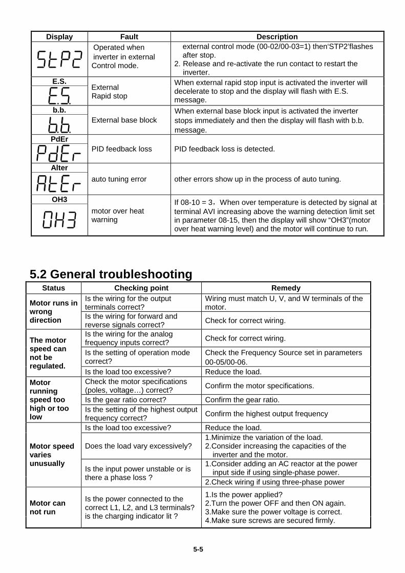
5-5
Display Fault Description
Operated when inverter in external Control mode.
external control mode (00-02/00-03=1) then‘STP2’flashes after stop.
2. Release and re-activate the run contact to restart the inverter.
E.S. External Rapid stop
When external rapid stop input is activated the inverter will decelerate to stop and the display will flash with E.S. message.
b.b. External base block
When external base block input is activated the inverter stops immediately and then the display will flash with b.b. message.
PdEr PID feedback loss PID feedback loss is detected.
Alter
auto tuning error other errors show up in the process of auto tuning.
OH3 motor over heat warning
If 08-10 = 3,When over temperature is detected by signal at terminal AVI increasing above the warning detection limit set in parameter 08-15, then the display will show “OH3”(motor over heat warning level) and the motor will continue to run.
5.2 General troubleshooting
Status Checking point Remedy
Motor runs in wrong direction
Is the wiring for the output terminals correct?
Wiring must match U, V, and W terminals of the motor.
Is the wiring for forward and reverse signals correct? Check for correct wiring.
The motor speed can not be regulated.
Is the wiring for the analog frequency inputs correct? Check for correct wiring.
Is the setting of operation mode correct?
Check the Frequency Source set in parameters 00-05/00-06.
Is the load too excessive? Reduce the load. Motor running speed too high or too low
Check the motor specifications (poles, voltage…) correct? Confirm the motor specifications.
Is the gear ratio correct? Confirm the gear ratio. Is the setting of the highest output frequency correct? Confirm the highest output frequency
Motor speed varies unusually
Is the load too excessive? Reduce the load.
Does the load vary excessively? 1.Minimize the variation of the load. 2.Consider increasing the capacities of the
inverter and the motor.
Is the input power unstable or is there a phase loss ?
1.Consider adding an AC reactor at the power input side if using single-phase power.
2.Check wiring if using three-phase power
Motor can not run
Is the power connected to the correct L1, L2, and L3 terminals? is the charging indicator lit ?
1.Is the power applied? 2.Turn the power OFF and then ON again. 3.Make sure the power voltage is correct. 4.Make sure screws are secured firmly.

5-6
Status Checking point Remedy Is there voltage across the output terminals T1, T2, and T3? Turn the power OFF and then ON again.
Is overload causing the motor to stall? Reduce the load so the motor will run.
Are there any abnormalities in the inverter? See error descriptions to check wiring and
correct if necessary. Is there a forward or reverse run command ? Has the analog frequency signal been input?
1.Is analog frequency input signal wiring correct? 2.Is voltage of frequency input correct?
Is the operation mode setting correct? Operate through the digital keypad
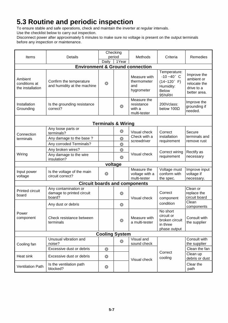
5-7
5.3 Routine and periodic inspection To ensure stable and safe operations, check and maintain the inverter at regular intervals. Use the checklist below to carry out inspection. Disconnect power after approximately 5 minutes to make sure no voltage is present on the output terminals before any inspection or maintenance.
Items Details Checking
period Methods Criteria Remedies Daily 1Year
Environment & Ground connection
Ambient conditions at the installation
Confirm the temperature and humidity at the machine ◎
Measure with thermometer and hygrometer
Temperature: -10 ~40°C (14~120°F) Humidity: Below 95%RH
Improve the ambient or relocate the drive to a better area.
Installation Grounding
Is the grounding resistance correct? ◎
Measure the resistance with a multi-tester
200Vclass: below 100Ω
Improve the grounding if needed.
Terminals & Wiring
Connection terminals
Any loose parts or terminals? ◎ Visual check
Check with a screwdriver
Correct installation requirement
Secure terminals and remove rust
Any damage to the base ? ◎ Any corroded Terminals? ◎
Wiring Any broken wires? ◎
Visual check Correct wiring requirement
Rectify as necessary Any damage to the wire
insulation? ◎
voltage
Input power voltage
Is the voltage of the main circuit correct? ◎
Measure the voltage with a multi-tester
Voltage must conform with the spec.
Improve input voltage if necessary.
Circuit boards and components
Printed circuit board
Any contamination or damage to printed circuit board?
◎ Visual check
Correct component condition
Clean or replace the circuit board
Power component
Any dust or debris ◎ Clean components
Check resistance between terminals ◎ Measure with
a multi-tester
No short circuit or broken circuit in three phase output
Consult with the supplier
Cooling System
Cooling fan Unusual vibration and noise? ◎ Visual and
sound check
Correct cooling
Consult with the supplier
Excessive dust or debris ◎
Visual check
Clean the fan
Heat sink Excessive dust or debris ◎ Clean up debris or dust
Ventilation Path Is the ventilation path blocked? ◎ Clear the
path
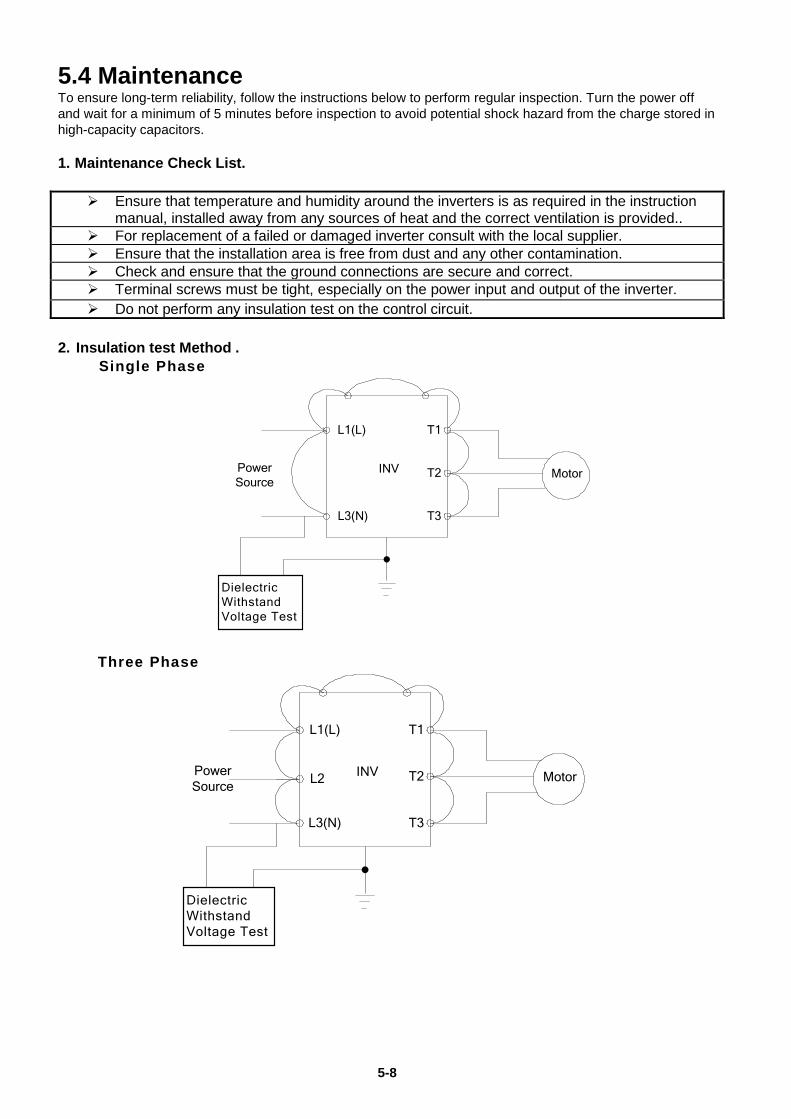
5-8
5.4 Maintenance To ensure long-term reliability, follow the instructions below to perform regular inspection. Turn the power off and wait for a minimum of 5 minutes before inspection to avoid potential shock hazard from the charge stored in high-capacity capacitors. 1. Maintenance Check List.
Ensure that temperature and humidity around the inverters is as required in the instruction manual, installed away from any sources of heat and the correct ventilation is provided..
For replacement of a failed or damaged inverter consult with the local supplier. Ensure that the installation area is free from dust and any other contamination. Check and ensure that the ground connections are secure and correct. Terminal screws must be tight, especially on the power input and output of the inverter. Do not perform any insulation test on the control circuit.
2. Insulation test Method .
Single Phase
INV
L1(L)
L3(N)
T1
T2
T3
Dielectric Withstand Voltage Test
Power Source
Motor
Three Phase
INV
L1(L)
L3(N)
T1
T2
T3
Dielectric Withstand Voltage Test
Power Source
MotorL2
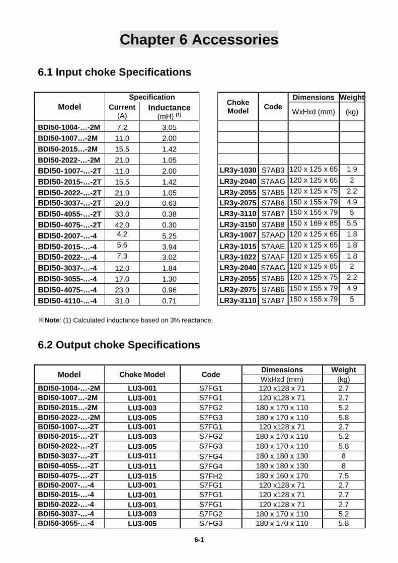
6-1
Chapter 6 Accessories
6.1 Input choke Specifications
Model Specification
Choke Model Code
Dimensions Weight Current
(A) Inductance
(mH) (1) WxHxd (mm) (kg)
BDI50-1004-…-2M 7.2 3.05
BDI50-1007…-2M 11.0 2.00
BDI50-2015…-2M 15.5 1.42
BDI50-2022-…-2M 21.0 1.05
BDI50-1007-…-2T 11.0 2.00 LR3y-1030 S7AB3 120 x 125 x 65 1.9
BDI50-2015-…-2T 15.5 1.42 LR3y-2040 S7AAG 120 x 125 x 65 2
BDI50-2022-…-2T 21.0 1.05 LR3y-2055 S7AB5 120 x 125 x 75 2.2 BDI50-3037-…-2T 20.0 0.63 LR3y-2075 S7AB6 150 x 155 x 79 4.9 BDI50-4055-…-2T 33.0 0.38 LR3y-3110 S7AB7 150 x 155 x 79 5
BDI50-4075-…-2T 42.0 0.30 LR3y-3150 S7AB8 150 x 169 x 85 5.5
BDI50-2007-…-4 4.2 5.25 LR3y-1007 S7AAD 120 x 125 x 65 1.8
BDI50-2015-…-4 5.6 3.94 LR3y-1015 S7AAE 120 x 125 x 65 1.8 BDI50-2022-…-4 7.3 3.02 LR3y-1022 S7AAF 120 x 125 x 65 1.8 BDI50-3037-…-4 12.0 1.84 LR3y-2040 S7AAG 120 x 125 x 65 2
BDI50-3055-…-4 17.0 1.30 LR3y-2055 S7AB5 120 x 125 x 75 2.2
BDI50-4075-…-4 23.0 0.96 LR3y-2075 S7AB6 150 x 155 x 79 4.9
BDI50-4110-…-4 31.0 0.71 LR3y-3110 S7AB7 150 x 155 x 79 5 ※Note: (1) Calculated inductance based on 3% reactance.
6.2 Output choke Specifications
Model Choke Model Code Dimensions Weight WxHxd (mm) (kg)
BDI50-1004-…-2M LU3-001 S7FG1 120 x128 x 71 2.7 BDI50-1007…-2M LU3-001 S7FG1 120 x128 x 71 2.7 BDI50-2015…-2M LU3-003 S7FG2 180 x 170 x 110 5.2 BDI50-2022-…-2M LU3-005 S7FG3 180 x 170 x 110 5.8 BDI50-1007-…-2T LU3-001 S7FG1 120 x128 x 71 2.7 BDI50-2015-…-2T LU3-003 S7FG2 180 x 170 x 110 5.2 BDI50-2022-…-2T LU3-005 S7FG3 180 x 170 x 110 5.8 BDI50-3037-…-2T LU3-011 S7FG4 180 x 180 x 130 8 BDI50-4055-…-2T LU3-011 S7FG4 180 x 180 x 130 8 BDI50-4075-…-2T LU3-015 S7FH2 180 x 160 x 170 7.5 BDI50-2007-…-4 LU3-001 S7FG1 120 x128 x 71 2.7 BDI50-2015-…-4 LU3-001 S7FG1 120 x128 x 71 2.7 BDI50-2022-…-4 LU3-001 S7FG1 120 x128 x 71 2.7 BDI50-3037-…-4 LU3-003 S7FG2 180 x 170 x 110 5.2 BDI50-3055-…-4 LU3-005 S7FG3 180 x 170 x 110 5.8
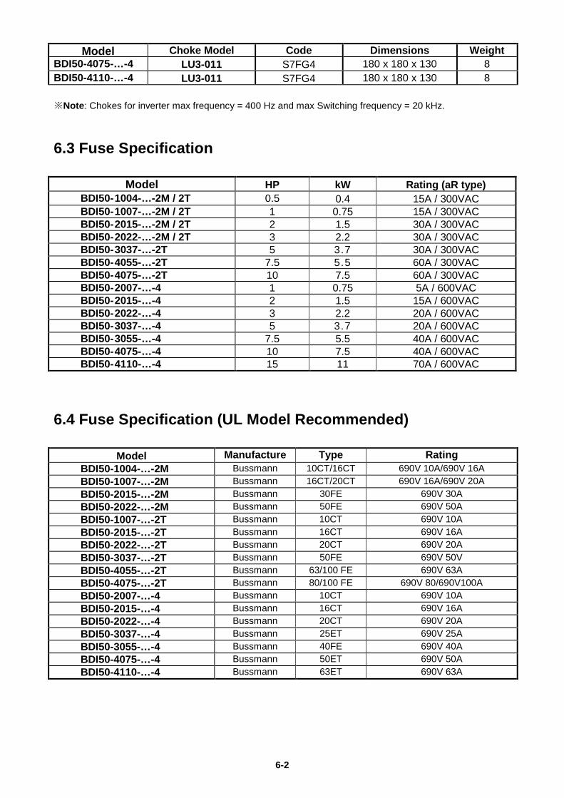
6-2
Model Choke Model Code Dimensions Weight BDI50-4075-…-4 LU3-011 S7FG4 180 x 180 x 130 8 BDI50-4110-…-4 LU3-011 S7FG4 180 x 180 x 130 8 ※Note: Chokes for inverter max frequency = 400 Hz and max Switching frequency = 20 kHz.
6.3 Fuse Specification
Model HP kW Rating (aR type) BDI50-1004-…-2M / 2T 0.5 0.4 15A / 300VAC BDI50-1007-…-2M / 2T 1 0.75 15A / 300VAC BDI50-2015-…-2M / 2T 2 1.5 30A / 300VAC BDI50-2022-…-2M / 2T 3 2.2 30A / 300VAC BDI50-3037-…-2T 5 3.7 30A / 300VAC BDI50-4055-…-2T 7.5 5.5 60A / 300VAC BDI50-4075-…-2T 10 7.5 60A / 300VAC BDI50-2007-…-4 1 0.75 5A / 600VAC BDI50-2015-…-4 2 1.5 15A / 600VAC BDI50-2022-…-4 3 2.2 20A / 600VAC BDI50-3037-…-4 5 3.7 20A / 600VAC BDI50-3055-…-4 7.5 5.5 40A / 600VAC BDI50-4075-…-4 10 7.5 40A / 600VAC BDI50-4110-…-4 15 11 70A / 600VAC
6.4 Fuse Specification (UL Model Recommended)
Model Manufacture Type Rating BDI50-1004-…-2M Bussmann 10CT/16CT 690V 10A/690V 16A BDI50-1007-…-2M Bussmann 16CT/20CT 690V 16A/690V 20A BDI50-2015-…-2M Bussmann 30FE 690V 30A BDI50-2022-…-2M Bussmann 50FE 690V 50A BDI50-1007-…-2T Bussmann 10CT 690V 10A BDI50-2015-…-2T Bussmann 16CT 690V 16A BDI50-2022-…-2T Bussmann 20CT 690V 20A BDI50-3037-…-2T Bussmann 50FE 690V 50V BDI50-4055-…-2T Bussmann 63/100 FE 690V 63A BDI50-4075-…-2T Bussmann 80/100 FE 690V 80/690V100A BDI50-2007-…-4 Bussmann 10CT 690V 10A BDI50-2015-…-4 Bussmann 16CT 690V 16A BDI50-2022-…-4 Bussmann 20CT 690V 20A BDI50-3037-…-4 Bussmann 25ET 690V 25A BDI50-3055-…-4 Bussmann 40FE 690V 40A BDI50-4075-…-4 Bussmann 50ET 690V 50A BDI50-4110-…-4 Bussmann 63ET 690V 63A
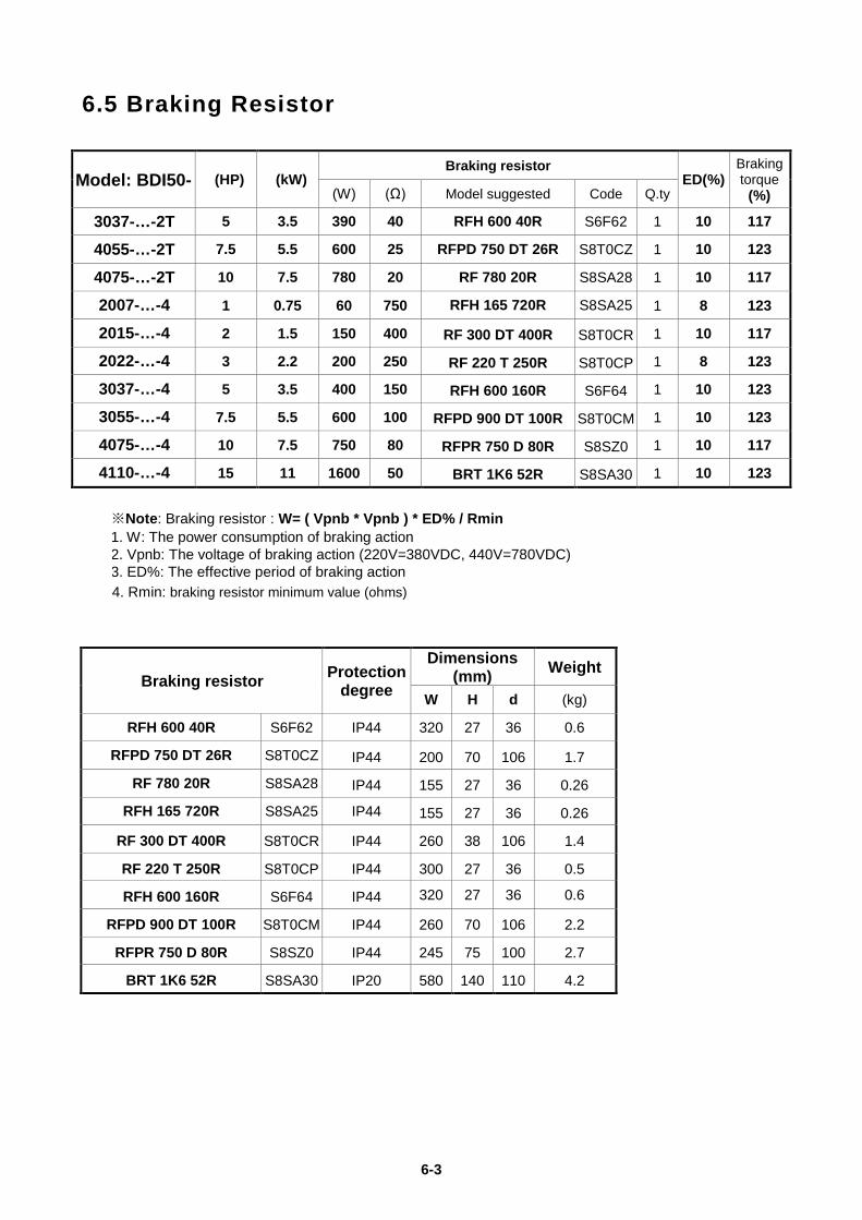
6-3
6.5 Braking Resistor
Model: BDI50- (HP) (kW) Braking resistor
ED(%) Braking torque
(%) (W) (Ω) Model suggested Code Q.ty
3037-…-2T 5 3.5 390 40 RFH 600 40R S6F62 1 10 117
4055-…-2T 7.5 5.5 600 25 RFPD 750 DT 26R S8T0CZ 1 10 123
4075-…-2T 10 7.5 780 20 RF 780 20R S8SA28 1 10 117
2007-…-4 1 0.75 60 750 RFH 165 720R S8SA25 1 8 123
2015-…-4 2 1.5 150 400 RF 300 DT 400R S8T0CR 1 10 117
2022-…-4 3 2.2 200 250 RF 220 T 250R S8T0CP 1 8 123
3037-…-4 5 3.5 400 150 RFH 600 160R S6F64 1 10 123
3055-…-4 7.5 5.5 600 100 RFPD 900 DT 100R S8T0CM 1 10 123
4075-…-4 10 7.5 750 80 RFPR 750 D 80R S8SZ0 1 10 117
4110-…-4 15 11 1600 50 BRT 1K6 52R S8SA30 1 10 123
※Note: Braking resistor : W= ( Vpnb * Vpnb ) * ED% / Rmin 1. W: The power consumption of braking action 2. Vpnb: The voltage of braking action (220V=380VDC, 440V=780VDC) 3. ED%: The effective period of braking action 4. Rmin: braking resistor minimum value (ohms)
Braking resistor Protection degree
Dimensions (mm) Weight
W H d (kg)
RFH 600 40R S6F62 IP44 320 27 36 0.6
RFPD 750 DT 26R S8T0CZ IP44 200 70 106 1.7
RF 780 20R S8SA28 IP44 155 27 36 0.26
RFH 165 720R S8SA25 IP44 155 27 36 0.26
RF 300 DT 400R S8T0CR IP44 260 38 106 1.4
RF 220 T 250R S8T0CP IP44 300 27 36 0.5
RFH 600 160R S6F64 IP44 320 27 36 0.6
RFPD 900 DT 100R S8T0CM IP44 260 70 106 2.2
RFPR 750 D 80R S8SZ0 IP44 245 75 100 2.7
BRT 1K6 52R S8SA30 IP20 580 140 110 4.2
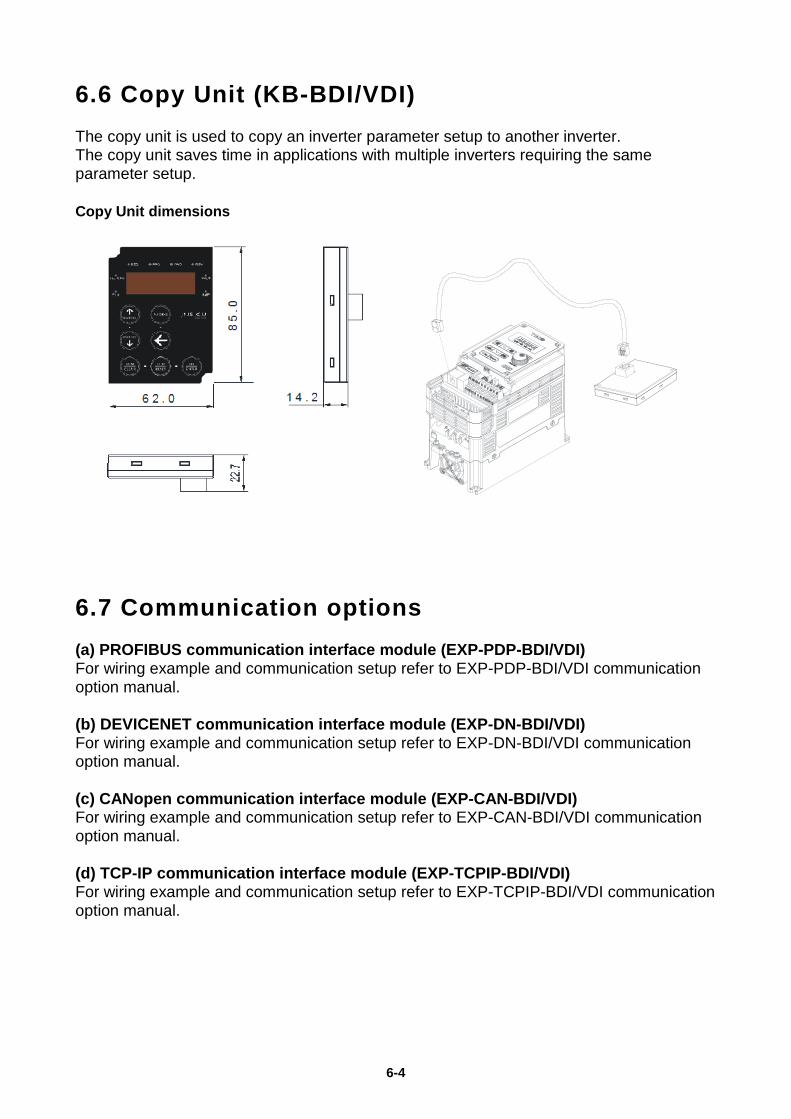
6-4
6.6 Copy Unit (KB-BDI/VDI) The copy unit is used to copy an inverter parameter setup to another inverter. The copy unit saves time in applications with multiple inverters requiring the same parameter setup. Copy Unit dimensions
6.7 Communication options (a) PROFIBUS communication interface module (EXP-PDP-BDI/VDI) For wiring example and communication setup refer to EXP-PDP-BDI/VDI communication option manual. (b) DEVICENET communication interface module (EXP-DN-BDI/VDI) For wiring example and communication setup refer to EXP-DN-BDI/VDI communication option manual. (c) CANopen communication interface module (EXP-CAN-BDI/VDI) For wiring example and communication setup refer to EXP-CAN-BDI/VDI communication option manual. (d) TCP-IP communication interface module (EXP-TCPIP-BDI/VDI) For wiring example and communication setup refer to EXP-TCPIP-BDI/VDI communication option manual.
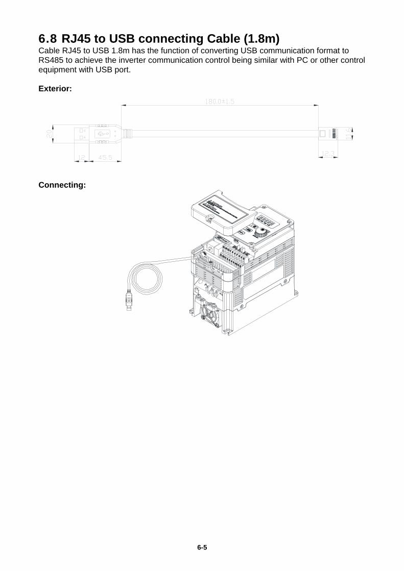
6-5
6.8 RJ45 to USB connecting Cable (1.8m) Cable RJ45 to USB 1.8m has the function of converting USB communication format to RS485 to achieve the inverter communication control being similar with PC or other control equipment with USB port. Exterior:
Connecting:
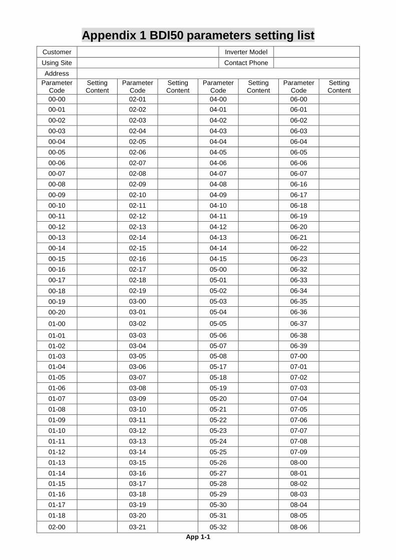
App 1-1
Appendix 1 BDI50 parameters setting list Customer Inverter Model Using Site Contact Phone Address
Parameter Code
Setting Content
Parameter Code
Setting Content
Parameter Code
Setting Content
Parameter Code
Setting Content
00-00 02-01 04-00 06-00 00-01 02-02 04-01 06-01 00-02 02-03 04-02 06-02 00-03 02-04 04-03 06-03 00-04 02-05 04-04 06-04 00-05 02-06 04-05 06-05 00-06 02-07 04-06 06-06 00-07 02-08 04-07 06-07 00-08 02-09 04-08 06-16 00-09 02-10 04-09 06-17 00-10 02-11 04-10 06-18 00-11 02-12 04-11 06-19 00-12 02-13 04-12 06-20 00-13 02-14 04-13 06-21 00-14 02-15 04-14 06-22 00-15 02-16 04-15 06-23 00-16 02-17 05-00 06-32 00-17 02-18 05-01 06-33 00-18 02-19 05-02 06-34 00-19 03-00 05-03 06-35 00-20 03-01 05-04 06-36
01-00 03-02 05-05 06-37
01-01 03-03 05-06 06-38 01-02 03-04 05-07 06-39 01-03 03-05 05-08 07-00 01-04 03-06 05-17 07-01 01-05 03-07 05-18 07-02 01-06 03-08 05-19 07-03 01-07 03-09 05-20 07-04 01-08 03-10 05-21 07-05 01-09 03-11 05-22 07-06 01-10 03-12 05-23 07-07 01-11 03-13 05-24 07-08 01-12 03-14 05-25 07-09 01-13 03-15 05-26 08-00 01-14 03-16 05-27 08-01 01-15 03-17 05-28 08-02 01-16 03-18 05-29 08-03 01-17 03-19 05-30 08-04 01-18 03-20 05-31 08-05
02-00 03-21 05-32 08-06
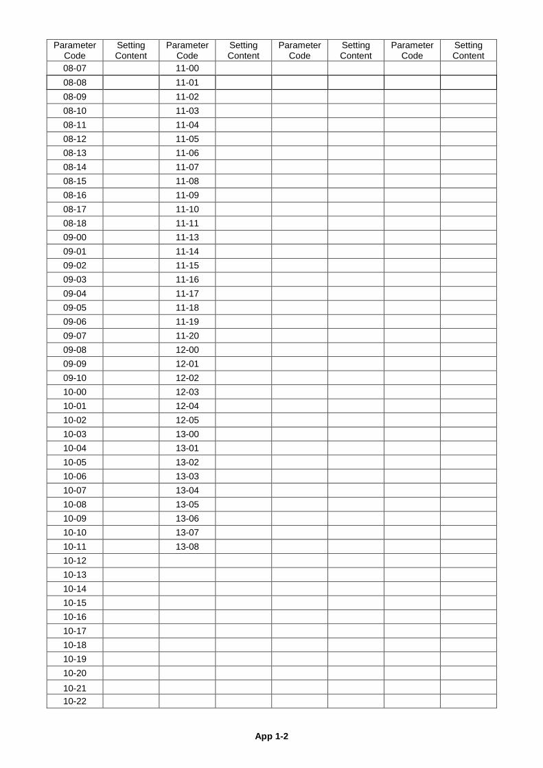
App 1-2
Parameter Code
Setting Content
Parameter Code
Setting Content
Parameter Code
Setting Content
Parameter Code
Setting Content
08-07 11-00 08-08 11-01 08-09 11-02 08-10 11-03 08-11 11-04 08-12 11-05 08-13 11-06 08-14 11-07 08-15 11-08 08-16 11-09 08-17 11-10 08-18 11-11 09-00 11-13 09-01 11-14 09-02 11-15 09-03 11-16 09-04 11-17 09-05 11-18 09-06 11-19 09-07 11-20 09-08 12-00 09-09 12-01 09-10 12-02 10-00 12-03 10-01 12-04 10-02 12-05 10-03 13-00 10-04 13-01 10-05 13-02 10-06 13-03 10-07 13-04 10-08 13-05 10-09 13-06 10-10 13-07 10-11 13-08 10-12 10-13 10-14 10-15 10-16 10-17 10-18 10-19 10-20 10-21 10-22
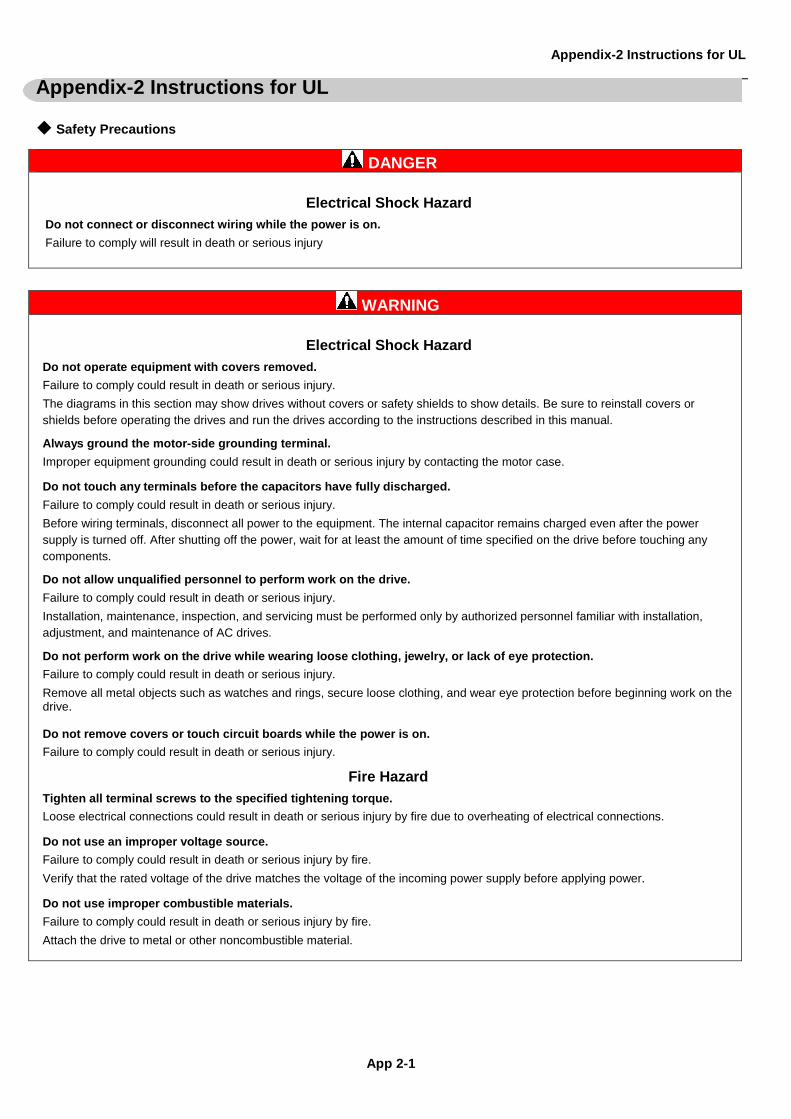
Appendix-2 Instructions for UL
App 2-1
Appendix-2 Instructions for UL ◆ Safety Precautions
DANGER Electrical Shock Hazard
Do not connect or disconnect wiring while the power is on. Failure to comply will result in death or serious injury
WARNING Electrical Shock Hazard
Do not operate equipment with covers removed. Failure to comply could result in death or serious injury. The diagrams in this section may show drives without covers or safety shields to show details. Be sure to reinstall covers or shields before operating the drives and run the drives according to the instructions described in this manual.
Always ground the motor-side grounding terminal. Improper equipment grounding could result in death or serious injury by contacting the motor case.
Do not touch any terminals before the capacitors have fully discharged. Failure to comply could result in death or serious injury. Before wiring terminals, disconnect all power to the equipment. The internal capacitor remains charged even after the power supply is turned off. After shutting off the power, wait for at least the amount of time specified on the drive before touching any components.
Do not allow unqualified personnel to perform work on the drive. Failure to comply could result in death or serious injury. Installation, maintenance, inspection, and servicing must be performed only by authorized personnel familiar with installation, adjustment, and maintenance of AC drives.
Do not perform work on the drive while wearing loose clothing, jewelry, or lack of eye protection. Failure to comply could result in death or serious injury. Remove all metal objects such as watches and rings, secure loose clothing, and wear eye protection before beginning work on the drive. Do not remove covers or touch circuit boards while the power is on. Failure to comply could result in death or serious injury.
Fire Hazard
Tighten all terminal screws to the specified tightening torque. Loose electrical connections could result in death or serious injury by fire due to overheating of electrical connections.
Do not use an improper voltage source. Failure to comply could result in death or serious injury by fire. Verify that the rated voltage of the drive matches the voltage of the incoming power supply before applying power.
Do not use improper combustible materials. Failure to comply could result in death or serious injury by fire. Attach the drive to metal or other noncombustible material.
Appendix-2 Instructions for UL
App 2-2
NOTICE Observe proper electrostatic discharge procedures (ESD) when handling the drive and circuit boards. Failure to comply may result in ESD damage to the drive circuitry.
Never connect or disconnect the motor from the drive while the drive is outputting voltage. Improper equipment sequencing could result in damage to the drive.
Do not use unshielded cable for control wiring. Failure to comply may cause electrical interference resulting in poor system performance. Use shielded twisted-pair wires and ground the shield to the ground terminal of the drive.
NOTICE Do not modify the drive circuitry. Failure to comply could result in damage to the drive and will void warranty. Gefran is not responsible for any modification of the product made by the user. This product must not be modified.
Check all the wiring to ensure that all connections are correct after installing the drive and connecting any other devices. Failure to comply could result in damage to the drive.
◆ UL Standards The UL/cUL mark applies to products in the United States and Canada and it means that UL has performed product testing and evaluation and determined that their stringent standards for product safety have been met. For a product to receive UL certification, all components inside that product must also receive UL certification.
UL/cUL Mark ◆ UL Standards Compliance This drive is tested in accordance with UL standard UL508C and complies with UL requirements. To ensure continued compliance when using this drive in combination with other equipment, meet the following conditions: ■ Installation Area Do not install the drive to an area greater than pollution severity 2 (UL standard). ■ Main Circuit Terminal Wiring UL approval requires crimp terminals when wiring the drive’s main circuit terminals. Use crimping tools as specified by the crimp terminal manufacturer. Gefran recommends crimp terminals made by NICHIFU for the insulation cap. The table below matches drives models with crimp terminals and insulation caps. Orders can be placed with a Gefran representative or directly with the Gefran sales department.
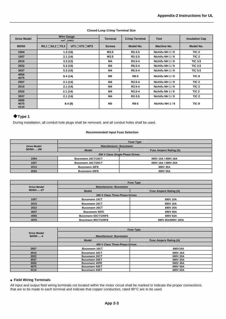
Appendix-2 Instructions for UL
App 2-3
Closed-Loop Crimp Terminal Size
Drive Model Wire Gauge Terminal Crimp Terminal Tool Insulation Cap
mm2 , (AWG)
BDI50 R/L1 S/L2 T/L3 U/T1 V/T2 W/T3 Screws Model No. Machine No. Model No.
1004 1.3 (16) M3.5 R2-3.5 Nichifu NH 1 / 9 TIC 2
1007 2.1 (14) M3.5 R2-3.5 Nichifu NH 1 / 9 TIC 2
2015 3.3 (12) M4 R3.5-4 Nichifu NH 1 / 9 TIC 3.5
2022 5.3 (10) M4 R5.5-4 Nichifu NH 1 / 9 TIC 3.5
3037 5.3 (10) M4 R5.5-4 Nichifu NH 1 / 9 TIC 5.5
4055 4075 8.4 (14) M5 R8-5 Nichifu NH 1 / 9 TIC 8
2007 2.1 (14) M4 R3.5-4 Nichifu NH 1 / 9 TIC 2
2015 2.1 (14) M4 R3.5-4 Nichifu NH 1 / 9 TIC 2
2022 2.1 (14) M4 R3.5-4 Nichifu NH 1 / 9 TIC 2
3037 2.1 (14) M4 R2-3.5 Nichifu NH 1 / 9 TIC 2
3055 4075 4110
8.4 (8) M5 R8-5 Nichifu NH 1 / 9 TIC 8
◆Type 1 During installation, all conduit hole plugs shall be removed, and all conduit holes shall be used.
Recommended Input Fuse Selection Fuse Type
Drive Model BDI50-…-2M
Manufacturer: Bussmann Model Fuse Ampere Rating (A)
200 V Class Single-Phase Drives 1004 Bussmann 10CT/16CT 690V 10A / 690V 16A 1007 Bussmann 16CT/20CT 690V 16A / 690V 20A 2015 Bussmann 30FE 690V 30A 2022 Bussmann 50FE 690V 50A
Fuse Type Drive Model
BDI50-…-2T Manufacturer: Bussmann
Model Fuse Ampere Rating (A) 200 V Class Three-Phase Drives
1007 Bussmann 10CT 690V 10A 2015 Bussmann 16CT 690V 16A 2022 Bussmann 20CT 690V 20A 3037 Bussmann 50FE 690V 50A 4055 Bussmann 63CT/100FE 690V 63A 4075 Bussmann 80CT/100FE 690V 80A/690V 100A
Fuse Type
Drive Model BDI50-…-4 Manufacturer: Bussmann
Model Fuse Ampere Rating (A) 400 V Class Three-Phase Drives
2007 Bussmann 10CT 690V10A 2015 Bussmann 16CT 690V 16A 2022 Bussmann 20CT 690V 20A 3037 Bussmann 25ET 690V 25A 3055 Bussmann 40FE 690V 40A 4075 Bussmann 50ET 690V 50A 4110 Bussmann 63ET 690V 63A
■ Field Wiring Terminals All input and output field wiring terminals not located within the motor circuit shall be marked to indicate the proper connections that are to be made to each terminal and indicate that copper conductors, rated 80°C are to be used.
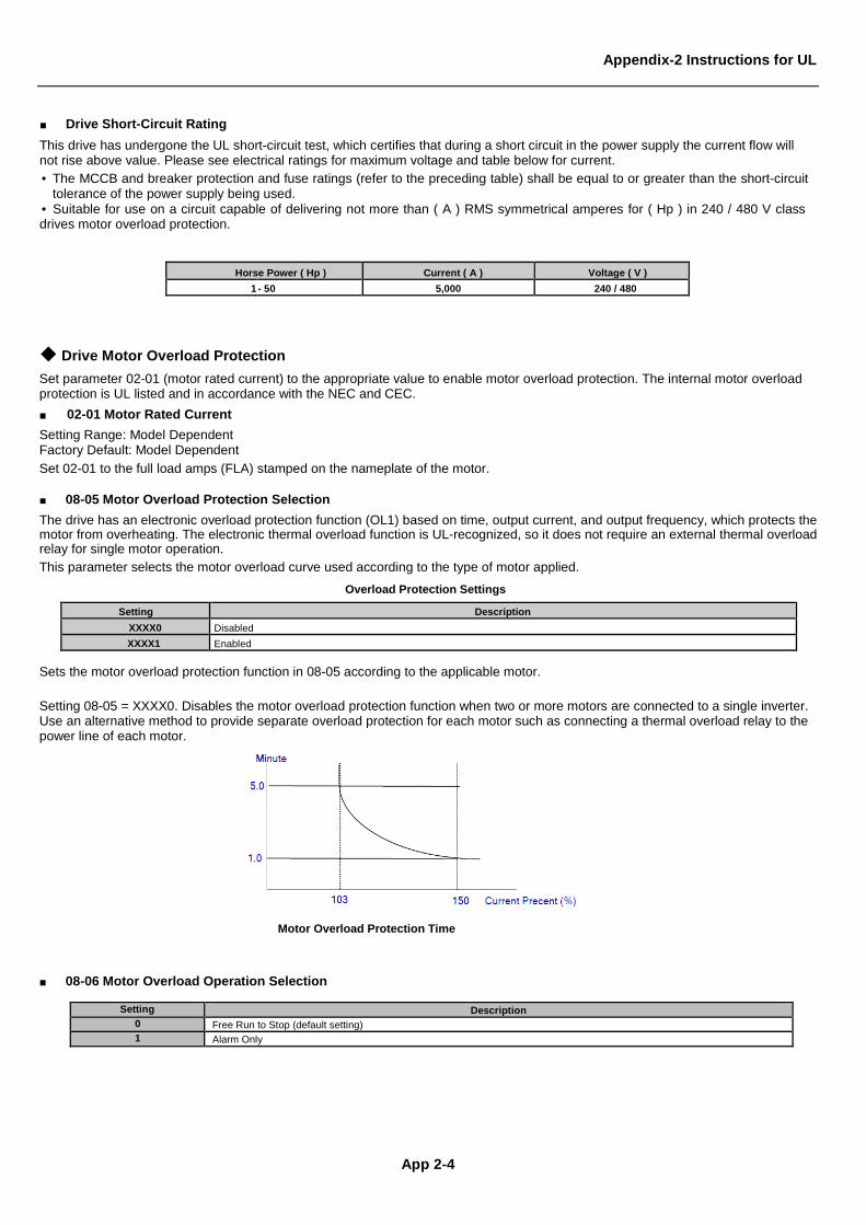
Appendix-2 Instructions for UL
App 2-4
■ Drive Short-Circuit Rating This drive has undergone the UL short-circuit test, which certifies that during a short circuit in the power supply the current flow will not rise above value. Please see electrical ratings for maximum voltage and table below for current. • The MCCB and breaker protection and fuse ratings (refer to the preceding table) shall be equal to or greater than the short-circuit
tolerance of the power supply being used. • Suitable for use on a circuit capable of delivering not more than ( A ) RMS symmetrical amperes for ( Hp ) in 240 / 480 V class drives motor overload protection.
Horse Power ( Hp ) Current ( A ) Voltage ( V ) 1 - 50 5,000 240 / 480
◆ Drive Motor Overload Protection Set parameter 02-01 (motor rated current) to the appropriate value to enable motor overload protection. The internal motor overload protection is UL listed and in accordance with the NEC and CEC. ■ 02-01 Motor Rated Current Setting Range: Model Dependent Factory Default: Model Dependent Set 02-01 to the full load amps (FLA) stamped on the nameplate of the motor. ■ 08-05 Motor Overload Protection Selection The drive has an electronic overload protection function (OL1) based on time, output current, and output frequency, which protects the motor from overheating. The electronic thermal overload function is UL-recognized, so it does not require an external thermal overload relay for single motor operation. This parameter selects the motor overload curve used according to the type of motor applied.
Overload Protection Settings
Setting Description XXXX0 Disabled XXXX1 Enabled
Sets the motor overload protection function in 08-05 according to the applicable motor. Setting 08-05 = XXXX0. Disables the motor overload protection function when two or more motors are connected to a single inverter. Use an alternative method to provide separate overload protection for each motor such as connecting a thermal overload relay to the power line of each motor.
Motor Overload Protection Time
■ 08-06 Motor Overload Operation Selection
Setting Description 0 Free Run to Stop (default setting) 1 Alarm Only
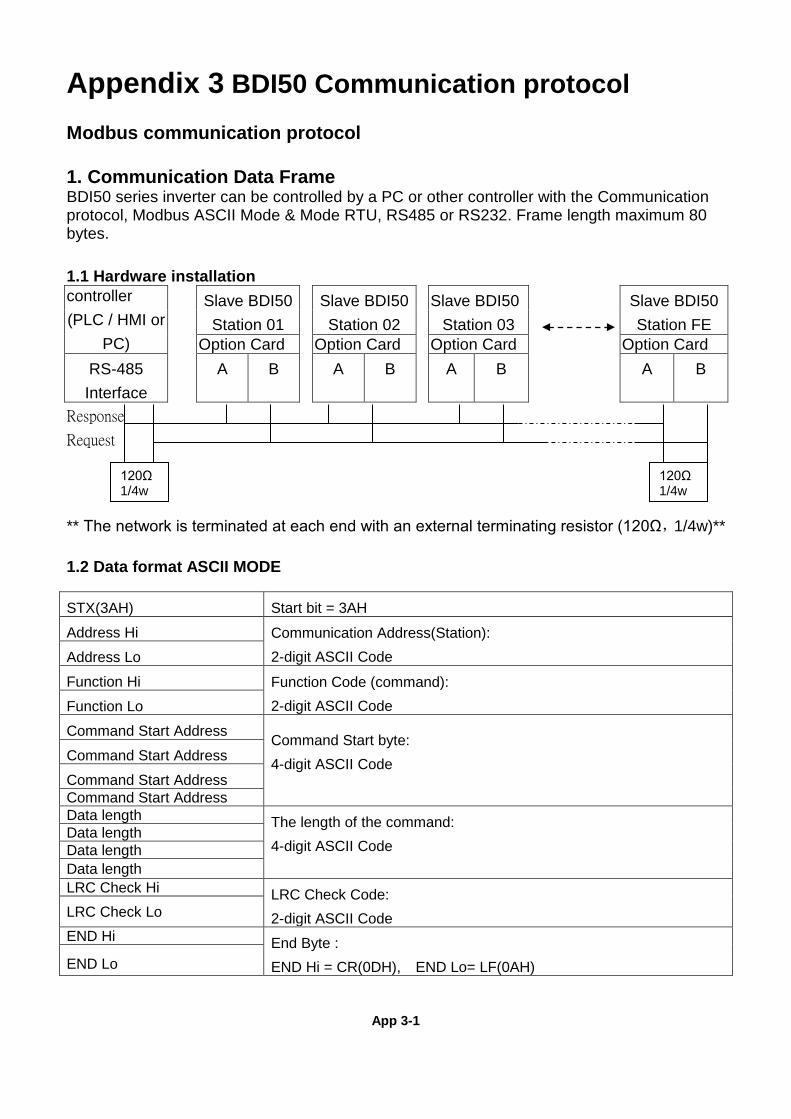
App 3-1
Appendix 3 BDI50 Communication protocol Modbus communication protocol 1. Communication Data Frame BDI50 series inverter can be controlled by a PC or other controller with the Communication protocol, Modbus ASCII Mode & Mode RTU, RS485 or RS232. Frame length maximum 80 bytes. 1.1 Hardware installation controller (PLC / HMI or
PC)
Slave BDI50 Station 01
Slave BDI50 Station 02
Slave BDI50 Station 03
Slave BDI50 Station FE
Option Card Option Card Option Card Option Card
RS-485 Interface
A B A B A B A B
Response
Request
** The network is terminated at each end with an external terminating resistor (120Ω,1/4w)**
1.2 Data format ASCII MODE
STX(3AH) Start bit = 3AH
Address Hi Communication Address(Station): 2-digit ASCII Code Address Lo
Function Hi Function Code (command): 2-digit ASCII Code Function Lo
Command Start Address Command Start byte: 4-digit ASCII Code
Command Start Address
Command Start Address Command Start Address Data length The length of the command:
4-digit ASCII Code
Data length Data length Data length LRC Check Hi LRC Check Code:
2-digit ASCII Code LRC Check Lo END Hi End Byte :
END Hi = CR(0DH), END Lo= LF(0AH) END Lo
120Ω 1/4w
120Ω 1/4w
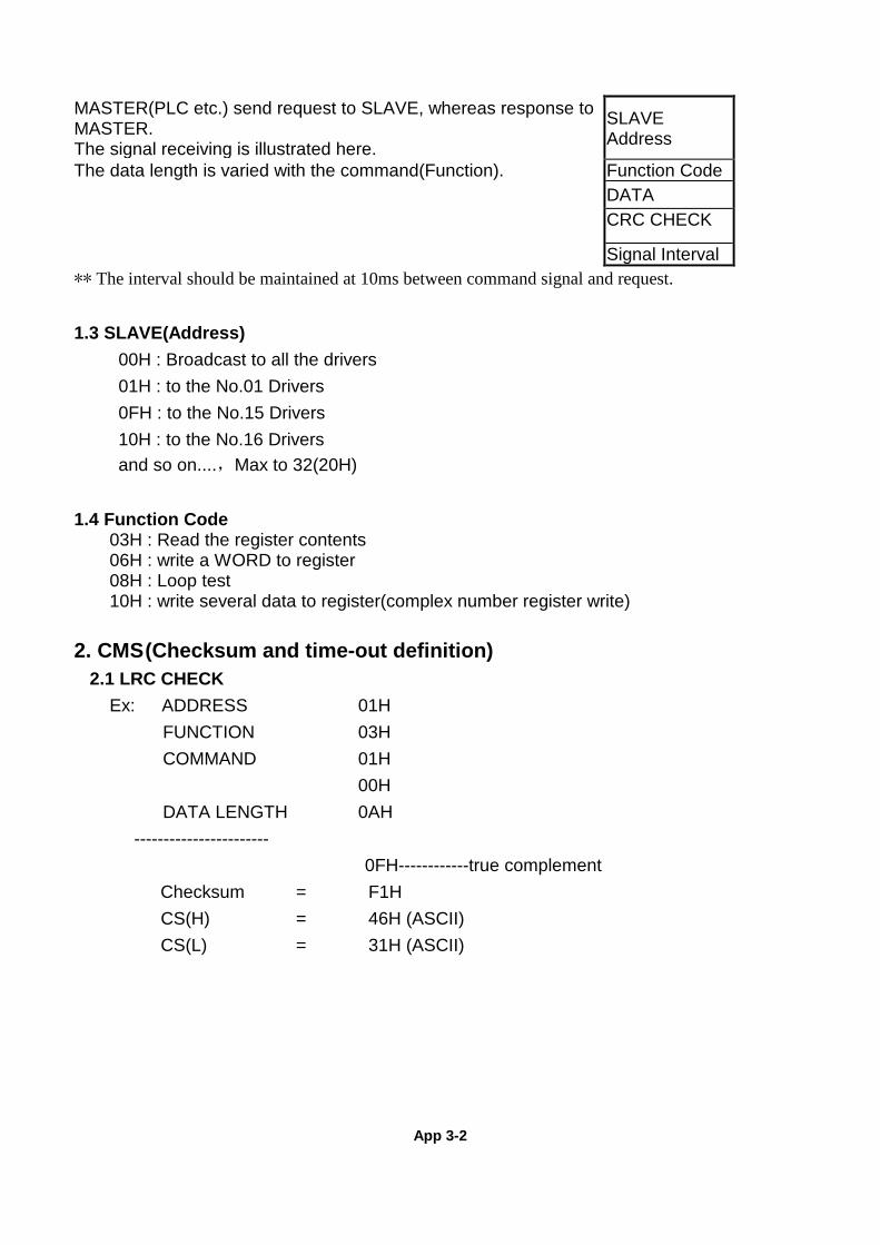
App 3-2
MASTER(PLC etc.) send request to SLAVE, whereas response to MASTER. The signal receiving is illustrated here.
SLAVE Address
The data length is varied with the command(Function). Function Code DATA
CRC CHECK
Signal Interval ** The interval should be maintained at 10ms between command signal and request. 1.3 SLAVE(Address) 00H : Broadcast to all the drivers 01H : to the No.01 Drivers 0FH : to the No.15 Drivers 10H : to the No.16 Drivers
and so on....,Max to 32(20H)
1.4 Function Code 03H : Read the register contents 06H : write a WORD to register 08H : Loop test 10H : write several data to register(complex number register write) 2. CMS (Checksum and time-out definition)
2.1 LRC CHECK Ex: ADDRESS 01H
FUNCTION 03H COMMAND 01H
00H DATA LENGTH 0AH
----------------------- 0FH------------true complement
Checksum = F1H CS(H) = 46H (ASCII) CS(L) = 31H (ASCII)
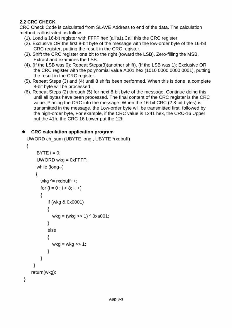
App 3-3
2.2 CRC CHECK: CRC Check Code is calculated from SLAVE Address to end of the data. The calculation method is illustrated as follow:
(1). Load a 16-bit register with FFFF hex (all’s1).Call this the CRC register. (2). Exclusive OR the first 8-bit byte of the message with the low-order byte of the 16-bit
CRC register, putting the result in the CRC register. (3). Shift the CRC register one bit to the right (toward the LSB), Zero-filling the MSB,
Extract and examines the LSB. (4). (If the LSB was 0): Repeat Steps(3)(another shift). (If the LSB was 1): Exclusive OR
the CRC register with the polynomial value A001 hex (1010 0000 0000 0001), putting the result in the CRC register.
(5). Repeat Steps (3) and (4) until 8 shifts been performed. When this is done, a complete 8-bit byte will be processed .
(6). Repeat Steps (2) through (5) for next 8-bit byte of the message, Continue doing this until all bytes have been processed. The final content of the CRC register is the CRC value. Placing the CRC into the message: When the 16-bit CRC (2 8-bit bytes) is transmitted in the message, the Low-order byte will be transmitted first, followed by the high-order byte, For example, if the CRC value is 1241 hex, the CRC-16 Upper put the 41h, the CRC-16 Lower put the 12h.
CRC calculation application program UWORD ch_sum (UBYTE long , UBYTE *rxdbuff) { BYTE i = 0; UWORD wkg = 0xFFFF; while (long--)
{ wkg ^= rxdbuff++; for (i = 0 ; i < 8; i++)
{ if (wkg & 0x0001)
{ wkg = (wkg >> 1) ^ 0xa001; } else
{ wkg = wkg >> 1; } } } return(wkg);
}
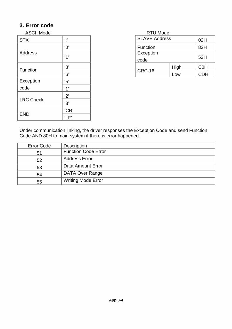
App 3-4
3. Error code ASCII Mode RTU Mode STX ‘:’ SLAVE Address 02H
Address ‘0’ Function 83H
‘1’ Exception
code 52H
Function ‘8’
CRC-16 High C0H
‘6’ Low CDH Exception
code ‘5’ ‘1’
LRC Check ‘2’ ‘8’
END ‘CR’ ‘LF’
Under communication linking, the driver responses the Exception Code and send Function Code AND 80H to main system if there is error happened.
Error Code Description
51 Function Code Error
52 Address Error
53 Data Amount Error
54 DATA Over Range
55 Writing Mode Error
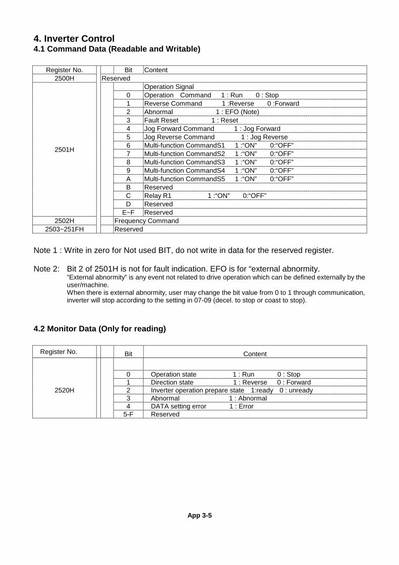
App 3-5
4. Inverter Control 4.1 Command Data (Readable and Writable)
Register No. Bit Content
2500H Reserved
2501H
Operation Signal 0 Operation Command 1 : Run 0 : Stop 1 Reverse Command 1 :Reverse 0 :Forward 2 Abnormal 1 : EFO (Note) 3 Fault Reset 1 : Reset 4 Jog Forward Command 1 : Jog Forward 5 Jog Reverse Command 1 : Jog Reverse 6 Multi-function CommandS1 1 :“ON” 0:“OFF” 7 Multi-function CommandS2 1 :“ON” 0:“OFF” 8 Multi-function CommandS3 1 :“ON” 0:“OFF” 9 Multi-function CommandS4 1 :“ON” 0:“OFF”
A Multi-function CommandS5 1 :“ON” 0:“OFF” B Reserved
C Relay R1 1 :“ON” 0:“OFF” D Reserved E~F Reserved
2502H Frequency Command 2503~251FH Reserved
Note 1 : Write in zero for Not used BIT, do not write in data for the reserved register. Note 2: Bit 2 of 2501H is not for fault indication. EFO is for “external abnormity. ”External abnormity” is any event not related to drive operation which can be defined externally by the
user/machine. When there is external abnormity, user may change the bit value from 0 to 1 through communication,
inverter will stop according to the setting in 07-09 (decel. to stop or coast to stop).
4.2 Monitor Data (Only for reading)
Register No. Bit Content
2520H
0 Operation state 1 : Run 0 : Stop 1 Direction state 1 : Reverse 0 : Forward 2 Inverter operation prepare state 1:ready 0 : unready 3 Abnormal 1 : Abnormal 4 DATA setting error 1 : Error
5-F Reserved
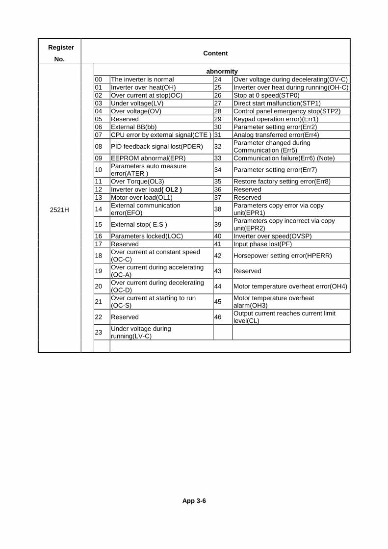
App 3-6
Register
No. Content
2521H
abnormity 00 The inverter is normal 24 Over voltage during decelerating(OV-C) 01 Inverter over heat(OH) 25 Inverter over heat during running(OH-C) 02 Over current at stop(OC) 26 Stop at 0 speed(STP0) 03 Under voltage(LV) 27 Direct start malfunction(STP1) 04 Over voltage(OV) 28 Control panel emergency stop(STP2) 05 Reserved 29 Keypad operation error)(Err1) 06 External BB(bb) 30 Parameter setting error(Err2) 07 CPU error by external signal(CTE ) 31 Analog transferred error(Err4)
08 PID feedback signal lost(PDER) 32 Parameter changed during Communication (Err5)
09 EEPROM abnormal(EPR) 33 Communication failure(Err6) (Note)
10 Parameters auto measure error(ATER ) 34 Parameter setting error(Err7)
11 Over Torque(OL3) 35 Restore factory setting error(Err8) 12 Inverter over load( OL2 ) 36 Reserved 13 Motor over load(OL1) 37 Reserved
14 External communication error(EFO) 38 Parameters copy error via copy
unit(EPR1)
15 External stop( E.S ) 39 Parameters copy incorrect via copy unit(EPR2)
16 Parameters locked(LOC) 40 Inverter over speed(OVSP) 17 Reserved 41 Input phase lost(PF)
18 Over current at constant speed (OC-C) 42 Horsepower setting error(HPERR)
19 Over current during accelerating (OC-A) 43 Reserved
20 Over current during decelerating (OC-D) 44 Motor temperature overheat error(OH4)
21 Over current at starting to run (OC-S) 45 Motor temperature overheat
alarm(OH3)
22 Reserved 46 Output current reaches current limit level(CL)
23 Under voltage during running(LV-C)
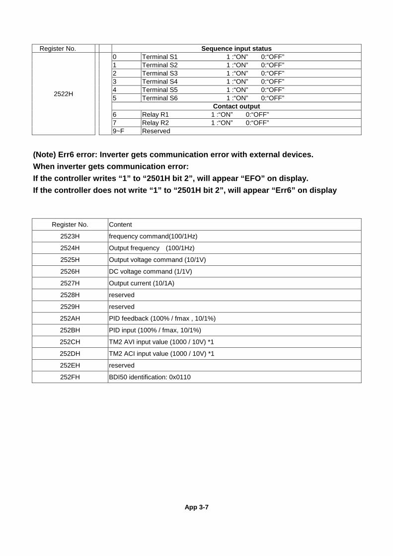
App 3-7
Register No. Sequence input status
2522H
0 Terminal S1 1 :“ON” 0:“OFF” 1 Terminal S2 1 :“ON” 0:“OFF” 2 Terminal S3 1 :“ON” 0:“OFF” 3 Terminal S4 1 :“ON” 0:“OFF” 4 Terminal S5 1 :“ON” 0:“OFF” 5 Terminal S6 1 :“ON” 0:“OFF”
Contact output 6 Relay R1 1 :“ON” 0:“OFF” 7 Relay R2 1 :“ON” 0:“OFF” 9~F Reserved
(Note) Err6 error: Inverter gets communication error with external devices. When inverter gets communication error: If the controller writes “1” to “2501H bit 2”, will appear “EFO” on display. If the controller does not write “1” to “2501H bit 2”, will appear “Err6” on display
Register No. Content
2523H frequency command(100/1Hz)
2524H Output frequency (100/1Hz)
2525H Output voltage command (10/1V)
2526H DC voltage command (1/1V)
2527H Output current (10/1A)
2528H reserved
2529H reserved
252AH PID feedback (100% / fmax , 10/1%)
252BH PID input (100% / fmax, 10/1%)
252CH TM2 AVI input value (1000 / 10V) *1
252DH TM2 ACI input value (1000 / 10V) *1
252EH reserved
252FH BDI50 identification: 0x0110
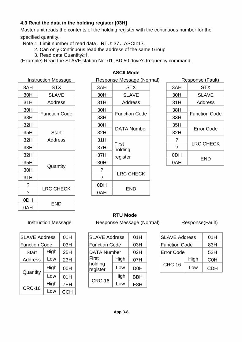
App 3-8
4.3 Read the data in the holding register [03H] Master unit reads the contents of the holding register with the continuous number for the specified quantity. Note:1. Limit number of read data,RTU: 37,ASCII:17.
2. Can only Continuous read the address of the same Group 3. Read data Quantity≥1.
(Example) Read the SLAVE station No: 01 ,BDI50 drive’s frequency command.
ASCII Mode Instruction Message Response Message (Normal) Response (Fault)
3AH STX 3AH STX 3AH STX 30H SLAVE
Address 30H SLAVE
Address 30H SLAVE
Address 31H 31H 31H 30H
Function Code 30H
Function Code 38H
Function Code 33H 33H 33H 32H
Start Address
30H DATA Number
35H Error Code
35H 32H 32H 32H 31H
First holding register
? LRC CHECK
33H 37H ? 32H
Quantity
37H 0DH END
35H 30H 0AH 30H ?
LRC CHECK
31H ? ?
LRC CHECK 0DH
END
? 0AH 0DH
END
0AH RTU Mode
Instruction Message Response Message (Normal) Response(Fault)
SLAVE Address 01H SLAVE Address 01H SLAVE Address 01H Function Code 03H Function Code 03H Function Code 83H
Start Address
High 25H DATA Number 02H Error Code 52H Low 23H First
holding register
High 07H CRC-16
High C0H
Quantity High 00H Low D0H Low CDH Low 01H
CRC-16 High BBH
CRC-16 High 7EH Low E8H Low CCH
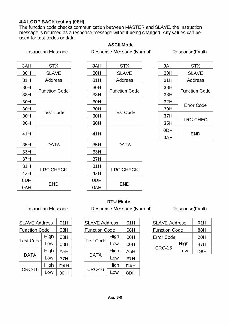
App 3-9
4.4 LOOP BACK testing [08H] The function code checks communication between MASTER and SLAVE, the Instruction message is returned as a response message without being changed. Any values can be used for test codes or data.
ASCII Mode Instruction Message Response Message (Normal) Response(Fault)
3AH STX 3AH STX 3AH STX 30H SLAVE
Address 30H SLAVE
Address 30H SLAVE
Address 31H 31H 31H 30H
Function Code 30H
Function Code 38H
Function Code 38H 38H 38H 30H
Test Code
30H
Test Code
32H Error Code
30H 30H 30H 30H 30H 37H
LRC CHEC 30H 30H 35H
41H
DATA
41H
DATA
0DH END
0AH 35H 35H 33H 33H 37H 37H 31H
LRC CHECK 31H
LRC CHECK
42H 42H 0DH
END 0DH
END
0AH 0AH
RTU Mode Instruction Message Response Message (Normal) Response(Fault)
SLAVE Address 01H SLAVE Address 01H SLAVE Address 01H Function Code 08H Function Code 08H Function Code 88H
Test Code High 00H
Test Code High 00H Error Code 20H
Low 00H Low 00H CRC-16
High 47H
DATA High A5H
DATA High A5H Low D8H
Low 37H Low 37H
CRC-16 High DAH
CRC-16 High DAH
Low 8DH Low 8DH
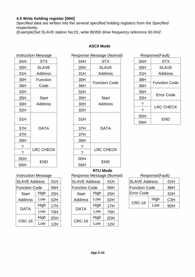
App 3-10
4.5 Write holding register [06H] Specified data are written into the several specified holding registers from the Specified respectively. (Example)Set SLAVE station No:01, write BDI50 drive frequency reference 60.0HZ.
ASCII Mode
Instruction Message Response Message (Normal) Response(Fault)
3AH STX 3AH STX 3AH STX 30H SLAVE
Address 30H SLAVE
Address 30H SLAVE
Address 31H 31H 31H 30H Function
Code 30H
Function Code 38H
Function Code 36H 36H 36H 32H
Start Address
32H Start
Address
35H Error Code
35H 35H 32H 30H 30H ?
LRC CHECK 32H 32H ?
31H
DATA
31H
DATA
0DH END
0AH 37H 37H 37H 37H 30H 30H
? LRC CHECK
? LRC CHECK
? ?
0DH END
0DH END
0AH 0AH
RTU Mode Instruction Message Response Message (Normal) Response(Fault)
SLAVE Address 01H SLAVE Address 01H SLAVE Address 01H Function Code 06H Function Code 06H Function Code 86H
Start Address
High 25H Start Address
High 25H Error Code 52H Low 02H Low 02H
CRC-16 High C3H
DATA High 17H
DATA High 17H Low 9DH
Low 70H Low 70H
CRC-16 High 2DH
CRC-16 High 2DH
Low 12H Low 12H
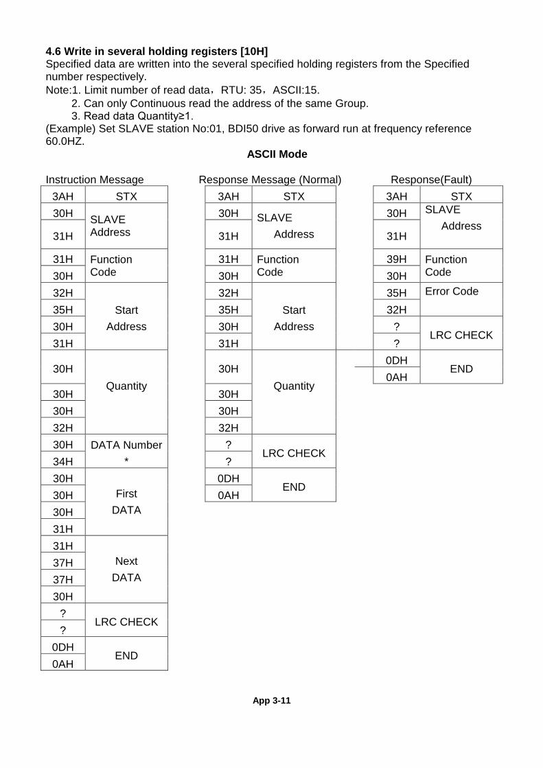
App 3-11
4.6 Write in several holding registers [10H] Specified data are written into the several specified holding registers from the Specified number respectively. Note:1. Limit number of read data,RTU: 35,ASCII:15.
2. Can only Continuous read the address of the same Group. 3. Read data Quantity≥1.
(Example) Set SLAVE station No:01, BDI50 drive as forward run at frequency reference 60.0HZ.
ASCII Mode
Instruction Message Response Message (Normal) Response(Fault) 3AH STX 3AH STX 3AH STX 30H SLAVE
Address
30H SLAVE
Address
30H SLAVE
Address 31H 31H 31H
31H Function Code
31H Function Code
39H Function Code 30H 30H 30H
32H Start
Address
32H Start
Address
35H Error Code 35H 35H 32H
30H 30H ? LRC CHECK
31H 31H ?
30H Quantity
30H Quantity
0DH END
0AH 30H 30H 30H 30H 32H 32H 30H DATA Number
* ?
LRC CHECK
34H ? 30H
First DATA
0DH END
30H 0AH 30H 31H 31H
Next DATA
37H 37H 30H
? LRC CHECK
?
0DH END
0AH
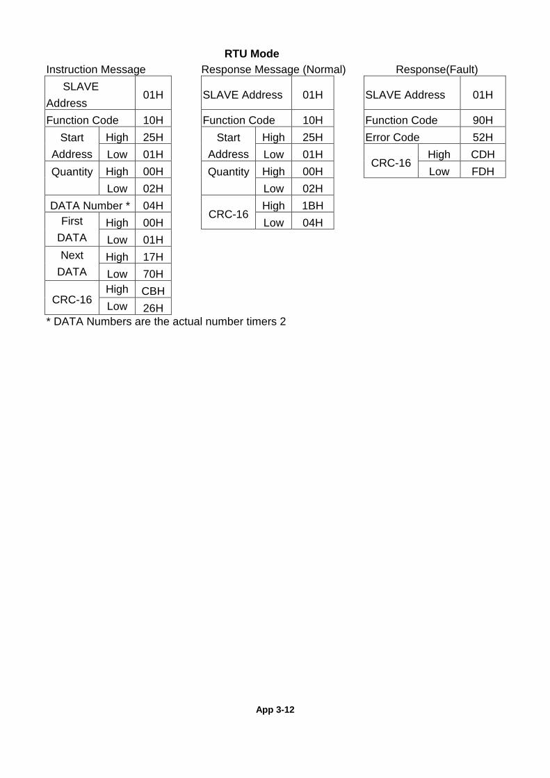
App 3-12
RTU Mode Instruction Message Response Message (Normal) Response(Fault) SLAVE Address
01H SLAVE Address 01H SLAVE Address 01H
Function Code 10H Function Code 10H Function Code 90H Start
Address High 25H Start
Address High 25H Error Code 52H
Low 01H Low 01H CRC-16
High CDH Quantity
High 00H Quantity
High 00H Low FDH
Low 02H Low 02H DATA Number * 04H
CRC-16 High 1BH
First DATA
High 00H Low 04H Low 01H
Next DATA
High 17H
Low 70H
CRC-16 High CBH
Low 26H * DATA Numbers are the actual number timers 2
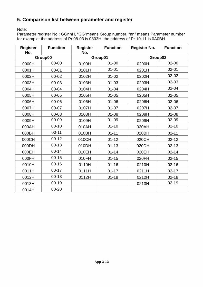
App 3-13
5. Comparison list between parameter and register Note: Parameter register No.: GGnnH, “GG”means Group number, “nn” means Parameter number for example: the address of Pr 08-03 is 0803H. the address of Pr 10-11 is 0A0BH.
Register No.
Function Register No.
Function Register No. Function
Group00 Group01 Group02 0000H 00-00 0100H 01-00 0200H 02-00
0001H 00-01 0101H 01-01 0201H 02-01
0002H 00-02 0102H 01-02 0202H 02-02
0003H 00-03 0103H 01-03 0203H 02-03
0004H 00-04 0104H 01-04 0204H 02-04
0005H 00-05 0105H 01-05 0205H 02-05 0006H 00-06 0106H 01-06 0206H 02-06 0007H 00-07 0107H 01-07 0207H 02-07 0008H 00-08 0108H 01-08 0208H 02-08 0009H 00-09 0109H 01-09 0209H 02-09
000AH 00-10 010AH 01-10 020AH 02-10
000BH 00-11 010BH 01-11 020BH 02-11 000CH 00-12 010CH 01-12 020CH 02-12 000DH 00-13 010DH 01-13 020DH 02-13 000EH 00-14 010EH 01-14 020EH 02-14 000FH 00-15 010FH 01-15 020FH 02-15 0010H 00-16 0110H 01-16 0210H 02-16 0011H 00-17 0111H 01-17 0211H 02-17 0012H 00-18 0112H 01-18 0212H 02-18 0013H 00-19 0213H 02-19
0014H 00-20
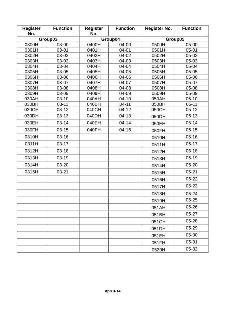
App 3-14
Register
No. Function Register
No. Function Register No. Function
Group03 Group04 Group05 0300H 03-00 0400H 04-00 0500H 05-00 0301H 03-01 0401H 04-01 0501H 05-01 0302H 03-02 0402H 04-02 0502H 05-02 0303H 03-03 0403H 04-03 0503H 05-03 0304H 03-04 0404H 04-04 0504H 05-04 0305H 03-05 0405H 04-05 0505H 05-05 0306H 03-06 0406H 04-06 0506H 05-06 0307H 03-07 0407H 04-07 0507H 05-07 0308H 03-08 0408H 04-08 0508H 05-08 0309H 03-09 0409H 04-09 0509H 05-09 030AH 03-10 040AH 04-10 050AH 05-10 030BH 03-11 040BH 04-11 050BH 05-11 030CH 03-12 040CH 04-12 050CH 05-12 030DH 03-13 040DH 04-13 050DH 05-13 030EH 03-14 040EH 04-14 050EH 05-14 030FH 03-15 040FH 04-15 050FH 05-15 0310H 03-16 0510H 05-16 0311H 03-17 0511H 05-17 0312H 03-18 0512H 05-18 0313H 03-19 0513H 05-19 0314H 03-20 0514H 05-20 0315H 03-21 0515H 05-21
0516H 05-22 0517H 05-23
0518H 05-24 0519H 05-25 051AH 05-26 051BH 05-27 051CH 05-28 051DH 05-29 051EH 05-30
051FH 05-31 0520H 05-32
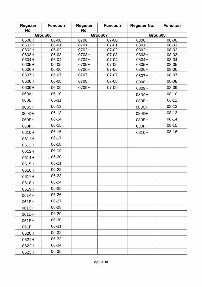
App 3-15
Register
No. Function Register
No. Function Register No. Function
Group06 Group07 Group08 0600H 06-00 0700H 07-00 0800H 08-00 0601H 06-01 0701H 07-01 0801H 08-01 0602H 06-02 0702H 07-02 0802H 08-02 0603H 06-03 0703H 07-03 0803H 08-03 0604H 06-04 0704H 07-04 0804H 08-04 0605H 06-05 0705H 07-05 0805H 08-05 0606H 06-06 0706H 07-06 0806H 08-06 0607H 06-07 0707H 07-07 0807H 08-07 0608H 06-08 0708H 07-08 0808H 08-08 0609H 06-09 0709H 07-09 0809H 08-09 060AH 06-10 080AH 08-10 060BH 06-11 080BH 08-11
060CH 06-12 080CH 08-12
060DH 06-13 080DH 08-13
060EH 06-14 080EH 08-14
060FH 06-15 080FH 08-15
0610H 06-16 0810H 08-16
0611H 06-17
0612H 06-18
0613H 06-19
0614H 06-20
0615H 06-21
0616H 06-22
0617H 06-23
0618H 06-24
0619H 06-25
061AH 06-26
061BH 06-27
061CH 06-28
061DH 06-29
061EH 06-30
061FH 06-31
0620H 06-32
0621H 06-33
0622H 06-34
0623H 06-35
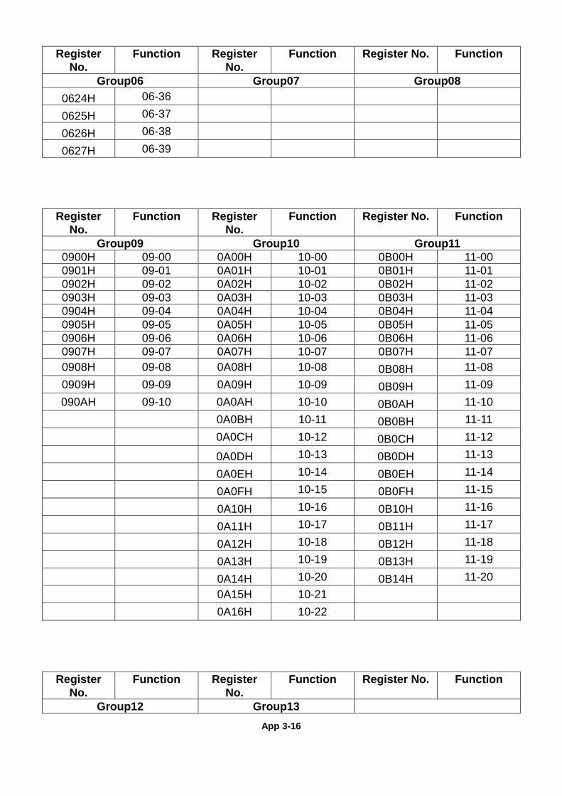
App 3-16
Register No.
Function Register No.
Function Register No. Function
Group06 Group07 Group08 0624H 06-36
0625H 06-37
0626H 06-38
0627H 06-39
Register No.
Function Register No.
Function Register No. Function
Group09 Group10 Group11 0900H 09-00 0A00H 10-00 0B00H 11-00 0901H 09-01 0A01H 10-01 0B01H 11-01 0902H 09-02 0A02H 10-02 0B02H 11-02 0903H 09-03 0A03H 10-03 0B03H 11-03 0904H 09-04 0A04H 10-04 0B04H 11-04 0905H 09-05 0A05H 10-05 0B05H 11-05 0906H 09-06 0A06H 10-06 0B06H 11-06 0907H 09-07 0A07H 10-07 0B07H 11-07 0908H 09-08 0A08H 10-08 0B08H 11-08 0909H 09-09 0A09H 10-09 0B09H 11-09 090AH 09-10 0A0AH 10-10 0B0AH 11-10
0A0BH 10-11 0B0BH 11-11 0A0CH 10-12 0B0CH 11-12 0A0DH 10-13 0B0DH 11-13 0A0EH 10-14 0B0EH 11-14 0A0FH 10-15 0B0FH 11-15 0A10H 10-16 0B10H 11-16 0A11H 10-17 0B11H 11-17 0A12H 10-18 0B12H 11-18 0A13H 10-19 0B13H 11-19 0A14H 10-20 0B14H 11-20
0A15H 10-21
0A16H 10-22
Register No.
Function Register No.
Function Register No. Function
Group12 Group13

App 3-17
0C00H 12-00 0D00H 13-00 0C01H 12-01 0D01H 13-01 0C02H 12-02 0D02H 13-02 0C03H 12-03 0D03H 13-03 0C04H 12-04 0D04H 13-04 0C05H 12-05 0D05H 13-05
0D06H 13-06 0D07H 13-07 0D08H 13-08
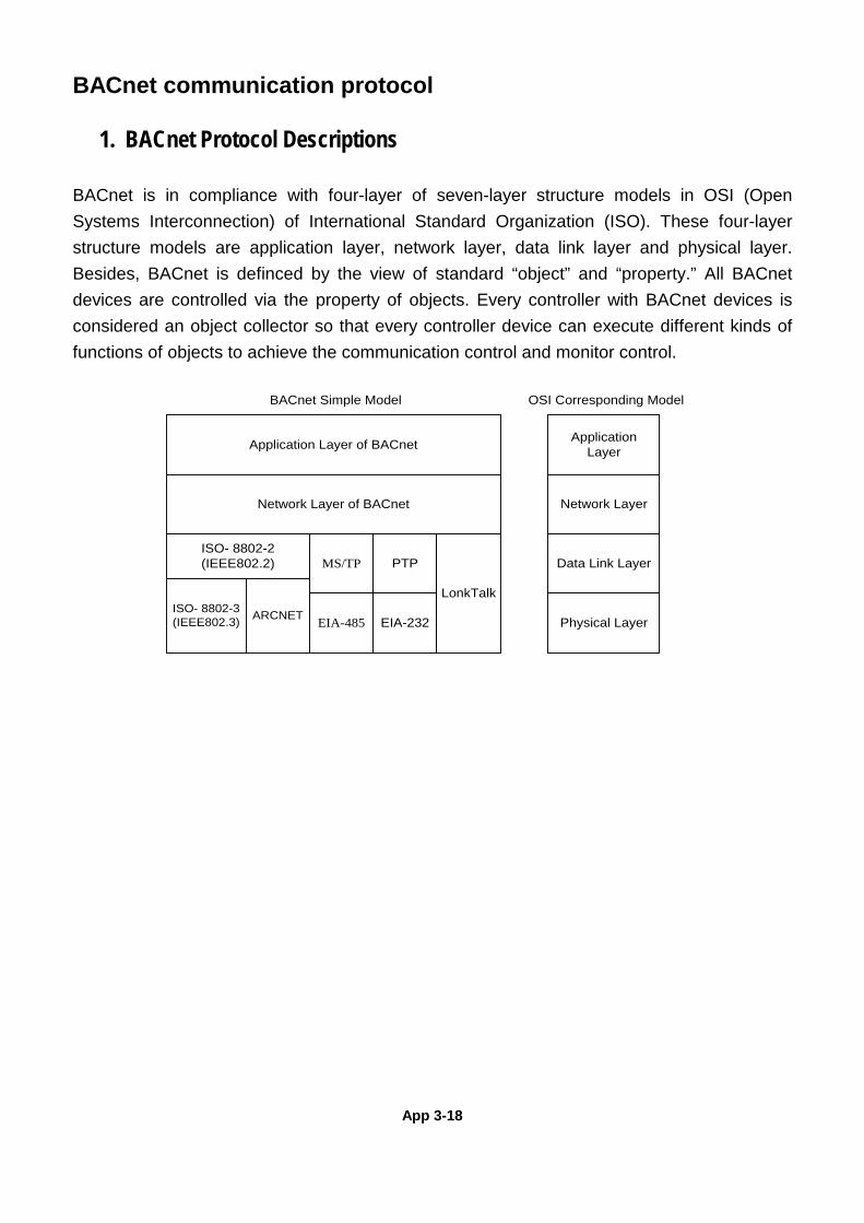
App 3-18
BACnet communication protocol
1. BACnet Protocol Descriptions
BACnet is in compliance with four-layer of seven-layer structure models in OSI (Open Systems Interconnection) of International Standard Organization (ISO). These four-layer structure models are application layer, network layer, data link layer and physical layer. Besides, BACnet is definced by the view of standard “object” and “property.” All BACnet devices are controlled via the property of objects. Every controller with BACnet devices is considered an object collector so that every controller device can execute different kinds of functions of objects to achieve the communication control and monitor control.
Application Layer
Network Layer
Data Link Layer
Physical Layer
Application Layer of BACnet
Network Layer of BACnet
ISO- 8802-2(IEEE802.2)
ISO- 8802-3(IEEE802.3) ARCNET
MS/TP PTP
EIA-485 EIA-232
LonkTalk
OSI Corresponding ModelBACnet Simple Model
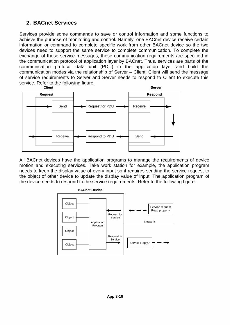
App 3-19
2. BACnet Services Services provide some commands to save or control information and some functions to achieve the purpose of monitoring and control. Namely, one BACnet device receive certain information or command to complete specific work from other BACnet device so the two devices need to support the same service to complete communication. To complete the exchange of these service messages, these communication requirements are specified in the communication protocol of application layer by BACnet. Thus, services are parts of the communication protocol data unit (PDU) in the application layer and build the communication modes via the relationship of Server – Client. Client will send the message of service requirements to Server and Server needs to respond to Client to execute this service. Refer to the following figure.
Request for PDU
Respond to PDU
Receive
SendReceive
Send
Request Respond
Client Server
All BACnet devices have the application programs to manage the requirements of device motion and executing services. Take work station for example, the application program needs to keep the display value of every input so it requires sending the service request to the object of other device to update the display value of input. The application program of the device needs to respond to the service requirements. Refer to the following figure.
Application Program
Object
Object
Object
Object
BACnet Device
Request for Service
Respond to Service
Network
Service requestRead property
Service Reply?
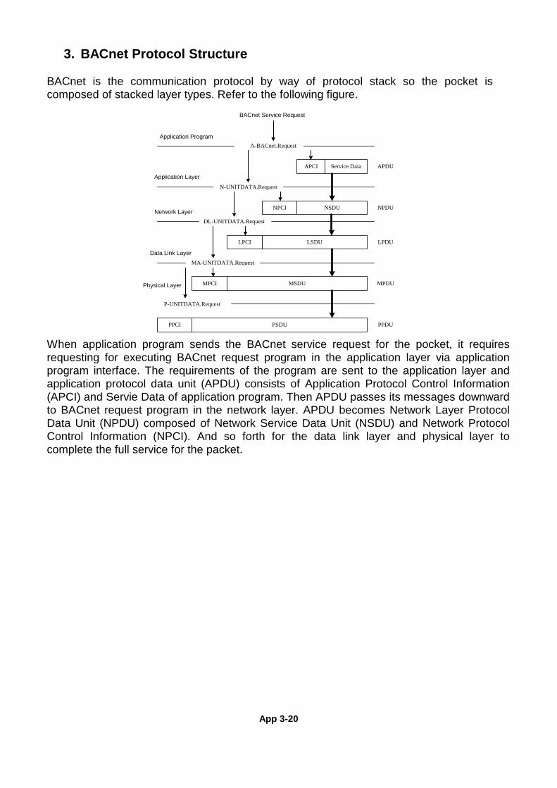
App 3-20
3. BACnet Protocol Structure BACnet is the communication protocol by way of protocol stack so the pocket is composed of stacked layer types. Refer to the following figure. When application program sends the BACnet service request for the pocket, it requires requesting for executing BACnet request program in the application layer via application program interface. The requirements of the program are sent to the application layer and application protocol data unit (APDU) consists of Application Protocol Control Information (APCI) and Servie Data of application program. Then APDU passes its messages downward to BACnet request program in the network layer. APDU becomes Network Layer Protocol Data Unit (NPDU) composed of Network Service Data Unit (NSDU) and Network Protocol Control Information (NPCI). And so forth for the data link layer and physical layer to complete the full service for the packet.
BACnet Service Request
Application Program
Application Layer
Network Layer
Data Link Layer
Physical Layer
A-BACnet.Request
N-UNITDATA.Request
DL-UNITDATA.Request
MA-UNITDATA.Request
P-UNITDATA.Request
APCI Service Data APDU
NSDUNPCI NPDU
LSDU LPDULPCI
MSDUMPCI
PSDUPPCI
MPDU
PPDU
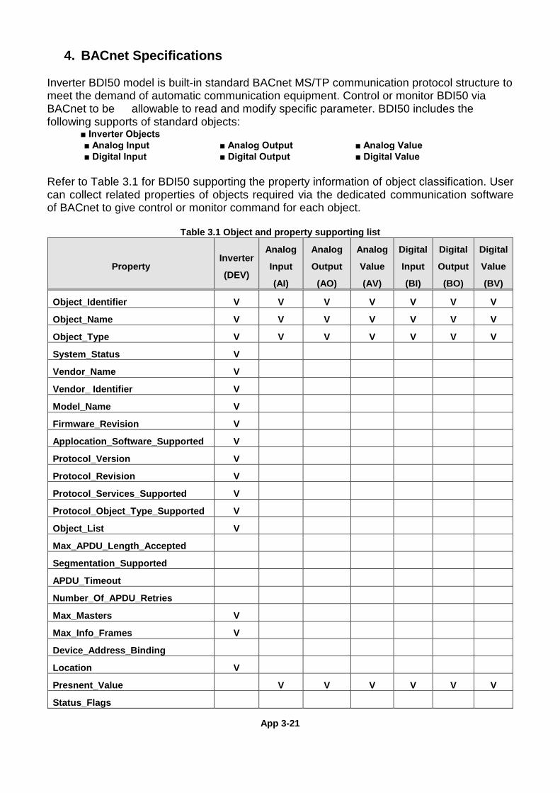
App 3-21
4. BACnet Specifications Inverter BDI50 model is built-in standard BACnet MS/TP communication protocol structure to meet the demand of automatic communication equipment. Control or monitor BDI50 via BACnet to be allowable to read and modify specific parameter. BDI50 includes the following supports of standard objects: ■ Inverter Objects ■ Analog Input ■ Analog Output ■ Analog Value ■ Digital Input ■ Digital Output ■ Digital Value Refer to Table 3.1 for BDI50 supporting the property information of object classification. User can collect related properties of objects required via the dedicated communication software of BACnet to give control or monitor command for each object.
Table 3.1 Object and property supporting list
Property Inverter
(DEV)
Analog
Input
(AI)
Analog
Output
(AO)
Analog
Value
(AV)
Digital
Input
(BI)
Digital
Output
(BO)
Digital
Value
(BV)
Object_Identifier V V V V V V V
Object_Name V V V V V V V
Object_Type V V V V V V V
System_Status V
Vendor_Name V
Vendor_ Identifier V
Model_Name V
Firmware_Revision V
Applocation_Software_Supported V
Protocol_Version V
Protocol_Revision V
Protocol_Services_Supported V
Protocol_Object_Type_Supported V
Object_List V
Max_APDU_Length_Accepted
Segmentation_Supported
APDU_Timeout
Number_Of_APDU_Retries
Max_Masters V
Max_Info_Frames V
Device_Address_Binding
Location V
Presnent_Value V V V V V V
Status_Flags
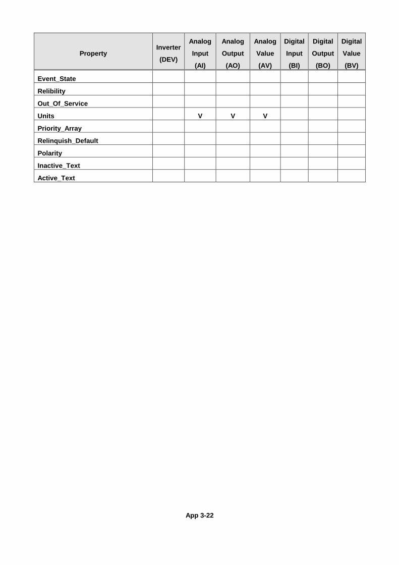
App 3-22
Property Inverter
(DEV)
Analog
Input
(AI)
Analog
Output
(AO)
Analog
Value
(AV)
Digital
Input
(BI)
Digital
Output
(BO)
Digital
Value
(BV)
Event_State
Relibility
Out_Of_Service
Units V V V
Priority_Array
Relinquish_Default
Polarity
Inactive_Text
Active_Text
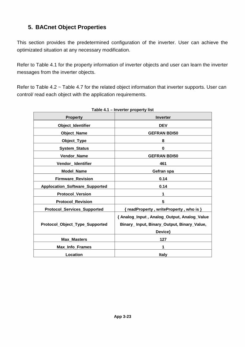
App 3-23
5. BACnet Object Properties
This section provides the predetermined configuration of the inverter. User can achieve the optimizated situation at any necessary modification. Refer to Table 4.1 for the property information of inverter objects and user can learn the inverter messages from the inverter objects. Refer to Table 4.2 ~ Table 4.7 for the related object information that inverter supports. User can control/ read each object with the application requirements.
Table 4.1 – Inverter property list
Property Inverter
Object_Identifier DEV
Object_Name GEFRAN BDI50
Object_Type 8
System_Status 0
Vendor_Name GEFRAN BDI50
Vendor_ Identifier 461
Model_Name Gefran spa
Firmware_Revision 0.14
Applocation_Software_Supported 0.14
Protocol_Version 1
Protocol_Revision 5
Protocol_Services_Supported { readProperty , writeProperty , who is }
Protocol_Object_Type_Supported
{ Analog_Input , Analog_Output, Analog_Value
Binary_ Input, Binary_Output, Binary_Value,
Device}
Max_Masters 127
Max_Info_Frames 1
Location Italy
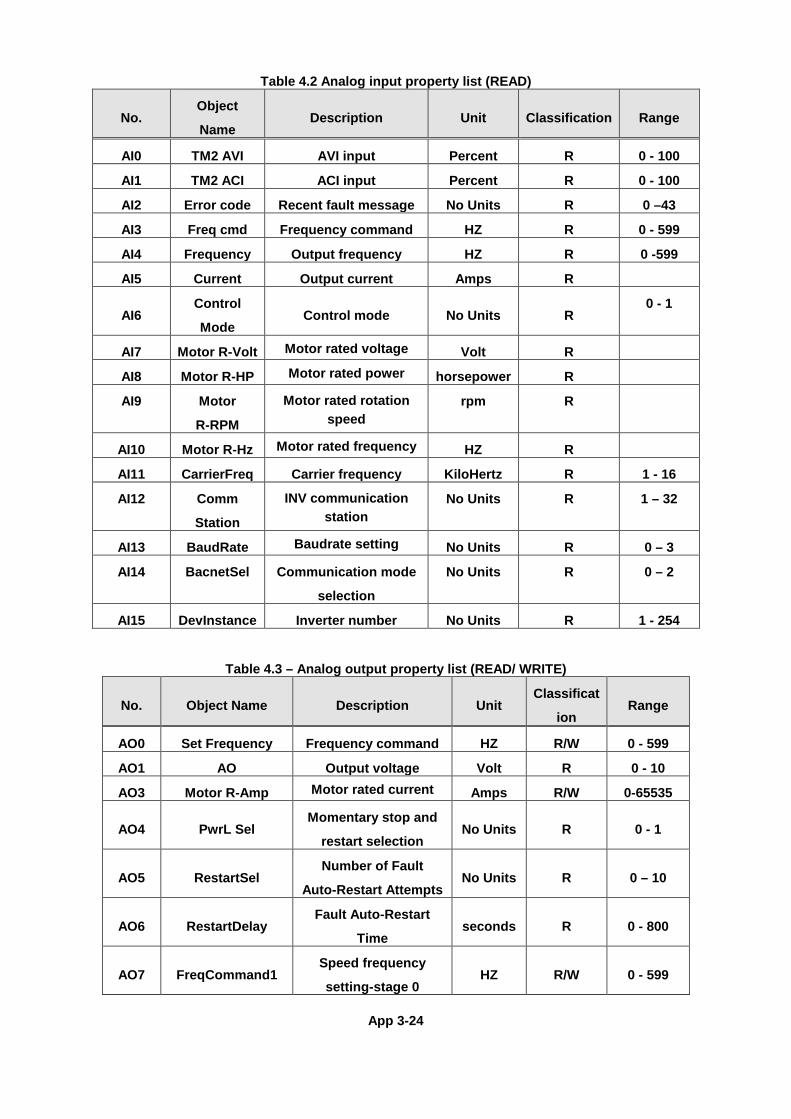
App 3-24
Table 4.2 Analog input property list (READ)
No. Object
Name Description Unit Classification Range
AI0 TM2 AVI AVI input Percent R 0 - 100
AI1 TM2 ACI ACI input Percent R 0 - 100
AI2 Error code Recent fault message No Units R 0 –43
AI3 Freq cmd Frequency command HZ R 0 - 599
AI4 Frequency Output frequency HZ R 0 -599
AI5 Current Output current Amps R
AI6 Control
Mode Control mode No Units R
0 - 1
AI7 Motor R-Volt Motor rated voltage Volt R
AI8 Motor R-HP Motor rated power horsepower R
AI9 Motor
R-RPM
Motor rated rotation speed
rpm R
AI10 Motor R-Hz Motor rated frequency HZ R
AI11 CarrierFreq Carrier frequency KiloHertz R 1 - 16
AI12 Comm
Station
INV communication station
No Units R 1 – 32
AI13 BaudRate Baudrate setting No Units R 0 – 3
AI14 BacnetSel Communication mode
selection
No Units R 0 – 2
AI15 DevInstance Inverter number No Units R 1 - 254
Table 4.3 – Analog output property list (READ/ WRITE)
No. Object Name Description Unit Classificat
ion Range
AO0 Set Frequency Frequency command HZ R/W 0 - 599
AO1 AO Output voltage Volt R 0 - 10
AO3 Motor R-Amp Motor rated current Amps R/W 0-65535
AO4 PwrL Sel Momentary stop and
restart selection No Units R 0 - 1
AO5 RestartSel Number of Fault
Auto-Restart Attempts No Units R 0 – 10
AO6 RestartDelay Fault Auto-Restart
Time seconds R 0 - 800
AO7 FreqCommand1 Speed frequency
setting-stage 0 HZ R/W 0 - 599
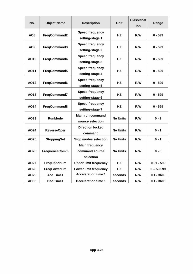
App 3-25
No. Object Name Description Unit Classificat
ion Range
AO8 FreqCommand2 Speed frequency
setting-stage 1 HZ R/W 0 - 599
AO9 FreqCommand3 Speed frequency
setting-stage 2 HZ R/W 0 - 599
AO10 FreqCommand4 Speed frequency
setting-stage 3 HZ R/W 0 - 599
AO11 FreqCommand5 Speed frequency
setting-stage 4 HZ R/W 0 - 599
AO12 FreqCommand6 Speed frequency
setting-stage 5 HZ R/W 0 - 599
AO13 FreqCommand7 Speed frequency
setting-stage 6 HZ R/W 0 - 599
AO14 FreqCommand8 Speed frequency
setting-stage 7 HZ R/W 0 - 599
AO23 RunMode Main run command
source selection No Units R/W 0 - 2
AO24 ReverseOper Direction locked
command No Units R/W 0 - 1
AO25 StoppingSel Stop modes selection No Units R/W 0 - 1
AO26 FrequenceComm
Main frequency
command source
selection
No Units R/W 0 - 6
AO27 FreqUpperLim Upper limit frequency HZ R/W 0.01 - 599
AO28 FreqLowerLim Lower limit frequency HZ R/W 0 – 598.99
AO29 Acc Time1 Acceleration time 1 seconds R/W 0.1 - 3600
AO30 Dec Time1 Deceleration time 1 seconds R/W 0.1 - 3600
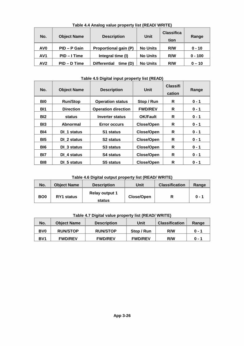
App 3-26
Table 4.4 Analog value property list (READ/ WRITE)
No. Object Name Description Unit Classifica
tion Range
AV0 PID – P Gain Proportional gain (P) No Units R/W 0 - 10
AV1 PID – I Time Integral time (I) No Units R/W 0 - 100
AV2 PID – D Time Differential time (D) No Units R/W 0 – 10
Table 4.5 Digital input property list (READ)
No. Object Name Description Unit Classifi
cation Range
BI0 Run/Stop Operation status Stop / Run R 0 - 1
BI1 Direction Operation direction FWD/REV R 0 - 1
BI2 status Inverter status OK/Fault R 0 - 1
BI3 Abnormal Error occurs Close/Open R 0 - 1
BI4 DI_1 status S1 status Close/Open R 0 - 1
BI5 DI_2 status S2 status Close/Open R 0 - 1
BI6 DI_3 status S3 status Close/Open R 0 - 1
BI7 DI_4 status S4 status Close/Open R 0 - 1
BI8 DI_5 status S5 status Close/Open R 0 - 1
Table 4.6 Digital output property list (READ/ WRITE) No. Object Name Description Unit Classification Range
BO0 RY1 status Relay output 1
status Close/Open R 0 - 1
Table 4.7 Digital value property list (READ/ WRITE)
No. Object Name Description Unit Classification Range
BV0 RUN/STOP RUN/STOP Stop / Run R/W 0 - 1
BV1 FWD/REV FWD/REV FWD/REV R/W 0 - 1
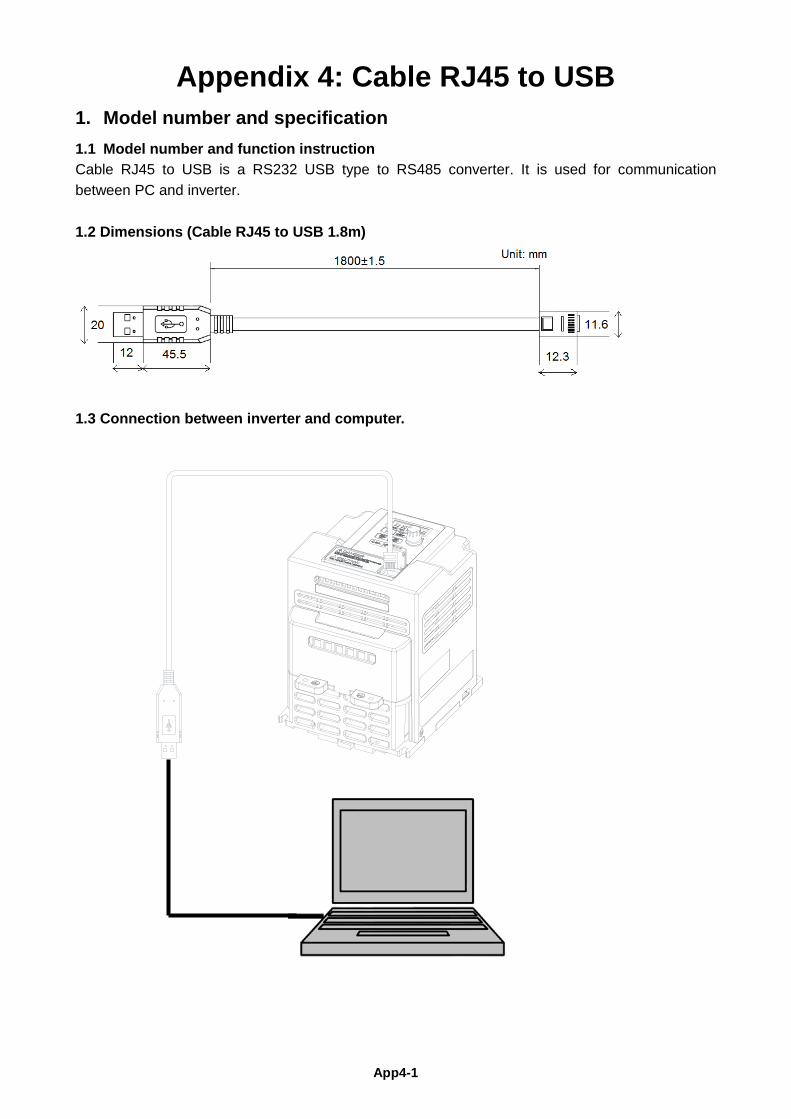
App4-1
Appendix 4: Cable RJ45 to USB 1. Model number and specification 1.1 Model number and function instruction Cable RJ45 to USB is a RS232 USB type to RS485 converter. It is used for communication between PC and inverter. 1.2 Dimensions (Cable RJ45 to USB 1.8m)
1.3 Connection between inverter and computer.
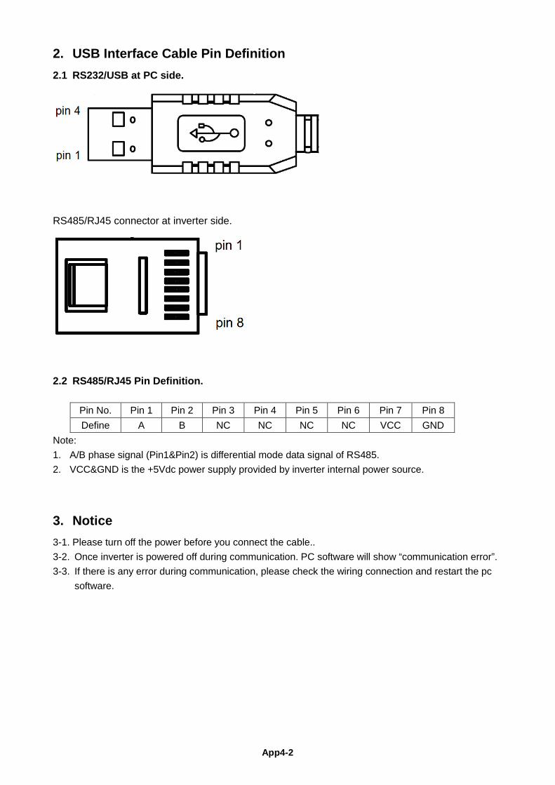
App4-2
2. USB Interface Cable Pin Definition 2.1 RS232/USB at PC side.
RS485/RJ45 connector at inverter side.
2.2 RS485/RJ45 Pin Definition.
Pin No. Pin 1 Pin 2 Pin 3 Pin 4 Pin 5 Pin 6 Pin 7 Pin 8 Define A B NC NC NC NC VCC GND
Note: 1. A/B phase signal (Pin1&Pin2) is differential mode data signal of RS485. 2. VCC&GND is the +5Vdc power supply provided by inverter internal power source.
3. Notice 3-1. Please turn off the power before you connect the cable.. 3-2. Once inverter is powered off during communication. PC software will show “communication error”. 3-3. If there is any error during communication, please check the wiring connection and restart the pc
software.
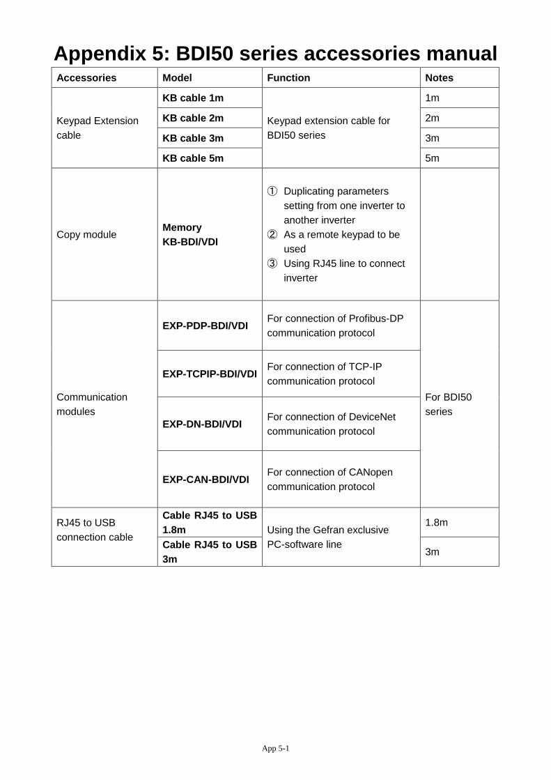
App 5-1
Appendix 5: BDI50 series accessories manual Accessories Model Function Notes
Keypad Extension cable
KB cable 1m
Keypad extension cable for BDI50 series
1m
KB cable 2m 2m
KB cable 3m 3m
KB cable 5m 5m
Copy module Memory KB-BDI/VDI
① Duplicating parameters setting from one inverter to another inverter
② As a remote keypad to be used
③ Using RJ45 line to connect inverter
Communication modules
EXP-PDP-BDI/VDI For connection of Profibus-DP communication protocol
For BDI50 series
EXP-TCPIP-BDI/VDI For connection of TCP-IP communication protocol
EXP-DN-BDI/VDI For connection of DeviceNet communication protocol
EXP-CAN-BDI/VDI For connection of CANopen communication protocol
RJ45 to USB connection cable
Cable RJ45 to USB 1.8m Using the Gefran exclusive
PC-software line
1.8m
Cable RJ45 to USB 3m
3m
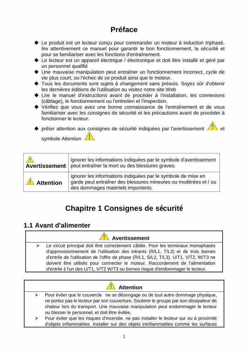
1
Préface
Le produit est un lecteur conçu pour commander un moteur à induction triphasé. lire attentivement ce manuel pour garantir le bon fonctionnement, la sécurité et pour se familiariser avec les fonctions d'entraînement.
Le lecteur est un appareil électrique / électronique et doit être installé et géré par un personnel qualifié
Une mauvaise manipulation peut entraîner un fonctionnement incorrect, cycle de vie plus court, ou l'échec de ce produit ainsi que le moteur.
Tous les documents sont sujets à changement sans préavis. Soyez sûr d'obtenir les dernières éditions de l'utilisation ou visitez notre site Web
Lire le manuel d'instructions avant de procéder à l'installation, les connexions (câblage), le fonctionnement ou l'entretien et l'inspection.
Vérifiez que vous avez une bonne connaissance de l'entraînement et de vous familiariser avec les consignes de sécurité et les précautions avant de procéder à fonctionner le lecteur.
prêter attention aux consignes de sécurité indiquées par l'avertissement et
symbole Attention .
Avertissement
ignorer les informations indiquées par le symbole d'avertissement peut entraîner la mort ou des blessures graves.
Attention
ignorer les informations indiquées par le symbole de mise en garde peut entraîner des blessures mineures ou modérées et / ou des dommages matériels importants.
Chapitre 1 Consignes de sécurité
1.1 Avant d'alimenter
Avertissement Le circuit principal doit être correctement câblée. Pour les terminaux monophasés
d'approvisionnement de l'utilisation des intrants (R/L1, T/L3) et de trois bornes d'entrée de l'utilisation de l'offre de phase (R/L1, S/L2, T/L3). U/T1, V/T2, W/T3 ne doivent être utilisés pour connecter le moteur. Raccordement de l'alimentation d'entrée à l'un des U/T1, V/T2 W/T3 ou bornes risque d'endommager le lecteur.
Attention Pour éviter que le couvercle ne se désengage ou de tout autre dommage physique,
ne portez pas le lecteur par son couverture. Soutenir le groupe par son dissipateur de chaleur lors du transport. Une mauvaise manipulation peut endommager le lecteur ou blesser le personnel, et doit être évitée.
Pour éviter que les risques d'incendie, ne pas installer le lecteur sur ou à proximité d'objets inflammables. Installer sur des objets ininflammables comme les surfaces
2
métalliques. Si plusieurs disques sont placés dans le même panneau de contrôle, fournir une
ventilation adéquate pour maintenir la température en dessous de 40 ° C/104 ° F (50 ° C/122 ° F sans housse de protection) pour éviter la surchauffe ou incendie.
Lors d'un retrait ou d'installation de l'opérateur numérique, éteignez-le d'abord, puis de suivre les instructions de ce manuel pour éviter les erreurs de l'opérateur ou de la perte de l'affichage causé par des connexions défectueuses.
Avertissement Lors d'un retrait ou d'installation de l'opérateur numérique, éteignez-le d'abord, puis
de suivre les instructions de ce manuel pour éviter les erreurs de l'opérateur ou de la perte de l'affichage causé par des connexions défectueuses....
1.2 Câblage
Avertissement Coupez toujours l'alimentation électrique avant de procéder à l'installation
d'entraînement et le câblage des terminaux utilisateurs. Le câblage doit être effectué par un personnel qualifié / électricien certifié. Assurez-vous que le lecteur est correctement mis à la terre. (220V Classe: impédance
de mise à la terre doit être inférieure à 100Ω Classe 440V:. Impédance de mise à la terre doit être inférieure à 10Ω.)
vérifier et tester mes circuits d'arrêt d'urgence après le câblage. (L’Installateur est responsable du câblage.)
Ne touchez jamais de l'entrée ou de lignes électriques de sortie permettant directement ou toute entrée ou de lignes de puissance de sortie à venir en contact avec le boîtier d'entraînement.
Ne pas effectuer un test de tenue en tension diélectrique (mégohmmètre) sur le disque dur ou cela va entraîner des dommages de lecture pour les composants semi-conducteurs.
Attention
La tension d'alimentation appliquée doit se conformer à la tension d'entrée spécifiée par le lecteur. (Voir la section signalétique du produit)
Raccorder la résistance de freinage et de l'unité de freinage sur les bornes assignées. Ne pas brancher une résistance de freinage directement sur les bornes CC P (+) et N
(-), sinon risque d'incendie. Utilisez des recommandations de la jauge de fil et les spécifications de couple. (Voir
Wire Gauge et la section de spécification de couple)。
Ne jamais brancher l'alimentation d'entrée aux bornes onduleur de sortie U/T1, V/T2, W/T3.
Ne pas brancher un contacteur ou interrupteur en série avec le variateur et le moteur. Ne branchez pas un facteur condensateur de correction de puissance ou suppresseur
de tension à la sortie du variateur。
S'assurer que l'interférence générée par l'entraînement et le moteur n'a pas d'incidence sur les périphériques.
3
1.3 Avant l'opération
Avertissement Assurez-vous que la capacité du disque correspond aux paramètres de notation avant
d'alimenter. Réduire le paramètre de la fréquence porteuse si le câble du variateur au moteur est
supérieure à 80 pi (25 m). Un courant de haute fréquence peut être générée par la capacité parasite entre les câbles et entraîner un déclenchement de surintensité du variateur, une augmentation du courant ou d'une lecture actuelle inexactes.
Veillez à installer tous les couvercles avant de l'allumer. Ne retirez pas les capots pendant que l'alimentation du lecteur est allumé, un choc électrique peut se produire autrement.
Ne pas actionner d'interrupteurs avec les mains mouillées, un choc électrique pourrait survenir autrement.
Ne touchez pas les bornes d'entraînement lorsqu'il est alimenté, même si le lecteur est arrêté, un choc électrique pourrait survenir autrement.
1.4 Configuration Paramètre
Attention
Ne branchez pas une charge pour le moteur tout en effectuant un auto-tune. Assurez-vous que le moteur peut fonctionner librement et il y a suffisamment d'espace
autour du moteur lors de l'exécution d'un auto-tune rotation.
1.5 Opération
Avertissement Veillez à installer tous les couvercles avant de l'allumer. Ne retirez pas les capots
pendant que l'alimentation du lecteur est allumé, un choc électrique peut se produire autrement.
Ne pas brancher ou débrancher le moteur pendant le fonctionnement. Le variateur pourrai se déclencher et ainsi endommager le lecteur.
Les opérations peuvent commencer soudainement si une alarme ou un défaut est réarmé avec un ordre de marche active. Assurez-vous qu'un ordre de marche est actif lors de la réinitialisation de l'alarme ou de défaut, autrement des accidents peuvent se produire.
Ne pas actionner d'interrupteurs avec les mains mouillées, un choc électrique pourrait survenir .
Un interrupteur d'urgence externe indépendant est fourni, qui s'arrête en urgence vers le bas la sortie de l'onduleur en cas de danger.
Si le redémarrage automatique après une récupération d'énergie est activée, le variateur démarrera automatiquement après le rétablissement du courant.
Assurez-vous qu'il est sûr de faire fonctionner le variateur et le moteur avant d'effectuer un auto-tune rotation.
Ne touchez pas les bornes d'entraînement lorsqu'il est alimenté même si l’onduleur s'est arrêté, un choc électrique pourrait survenir .
Ne pas contrôler les signaux sur les circuits pendant que le lecteur est en marche. Après la mise hors tension, le ventilateur de refroidissement peut continuer à
fonctionner pendant un certain temps.
4
Attention
Ne touchez pas les composants générant de la chaleur tels que radiateurs et des résistances de freinage.
Vérifiez soigneusement la performance du moteur ou de la machine avant d'utiliser à grande vitesse, sous peine de blessure.
Notez les réglages des paramètres liés à l'unité de freinage lorsque applicable. Ne pas utiliser la fonction de freinage d'entraînement pour un maintien mécanique,
sous peine de blessure. Ne pas contrôler les signaux sur les circuits pendant que le lecteur est en marche.
1.6 Entretien, Inspection et remplacement Avertissement
Attendre un minimum de 5 minutes après que l'alimentation a été débranchée avant de commencer une inspection. Vérifiez également que le voyant de charge est éteint et que la tension du bus cc a chuté au-dessous de 25Vdc.
Ne jamais toucher les bornes à haute tension dans le lecteur. Assurez-vous que l'alimentation du lecteur est débranché avant de démonter le
lecteur. Seul le personnel autorisé peuvent faire l'entretien, l'inspection et les opérations de
remplacement. (Enlevez les bijoux en métal tels que les montres et les bagues et utiliser des outils isolés.)
Attention
Le variateur peut être utilisé dans un environnement avec une gamme de température allant de 14 ° -104 ° F (10-40 ° C) et l'humidité relative de 95% sans condensation.
Le variateur doit être utilisé dans un environnement sans poussière, gaz, vapeur et humidité.
1.7 Mise au rebut du variateur
Attention jeter cet appareil avec soin comme un déchet industriel et selon les réglementations
locales nécessaires. Les condensateurs du circuit principal d'entraînement et circuits imprimés sont
considérés comme des déchets dangereux et ne doivent pas être brûlés. The Plastic enclosure and parts of the drive such as the top cover board will release
harmful gases if burned.
Motor over temperature protection is not provided.

Gef
ran
wo
rld
wid
e
GEFRAN S.p.A.Via Sebina 7425050 Provaglio d’Iseo (BS) ITALYPh. +39 030 98881Fax +39 030 [email protected]
Drive & Motion Control UnitVia Carducci 2421040 Gerenzano [VA] ITALYPh. +39 02 967601Fax +39 02 [email protected]
Technical Assistance : [email protected]
Customer Service : [email protected]. +39 02 96760500Fax +39 02 96760278
GEFRAN DEUTSCHLAND GMBH
Philipp-Reis-Straße 9aD-63500 SeligenstadtPh. +49 (0) 61828090Fax +49 (0) [email protected]
GEFRAN BENELUX NV
ENA 23 Zone 3, nr. 3910 Lammerdries-Zuid 14AB-2250 OLENPh. +32 (0) 14248181Fax +32 (0) [email protected]
GEFRAN SIEI - ASIA
31 Ubi Road 1 #02-07, Aztech Building, Singapore 408694Ph. +65 6 8418300Fax +65 6 [email protected]
SIEI AREG - GERMANY
Gottlieb-Daimler Strasse 17/3D-74385 - PleidelsheimPh. +49 (0) 7144 897360Fax +49 (0) 7144 [email protected]
GEFRAN UK LTD
Unit 7, Brook Business Centre54a Cowley Mill Road, Uxbridge, UB8 2FXPh. +44 (0) 8452 604555Fax +44 (0) 8452 604556 [email protected]
GEFRAN INDIA
Survey No. 191/A/1, Chinchwad Station Road, Chinchwad, Pune-411033, MaharashtraPh. +91 20 6614 6500Fax +91 20 6614 [email protected]
SENSORMATE AG
Steigweg 8,CH-8355 Aadorf, SwitzerlandPh. +41(0)52-2421818 Fax +41(0)52-3661884http://www.sensormate.ch
GEFRAN MIDDLE EAST ELEKTRIK VE ELEKTRONIK SAN. VE TIC. LTD. STI
Yesilkoy Mah. Ataturk Cad. No: 12/1 B1 Blok K:12 D: 389 Bakirkoy /Istanbul TURKIYE Ph. +90212 465 91 21Fax +90212 465 91 22
GEFRAN INC.
8 Lowell AvenueWINCHESTER - MA 01890Toll Free 1-888-888-4474Fax +1 (781) [email protected]
GEFRAN FRANCE SA
4, rue Jean Desparmet - BP 823769355 LYON Cedex 08Ph. +33 (0) 478770300Fax +33 (0) [email protected]
GEFRAN SIEI
Drives Technology Co., LtdNo. 1285, Beihe Road, JiadingDistrict, Shanghai, China 201807Ph. +86 21 69169898Fax +86 21 [email protected]
GEFRAN BRASIL
ELETROELETRôNICAAvenida Dr. Altino Arantes,377 Vila Clementino04042-032 SÂO PAULO - SPPh. +55 (0) 1155851133Fax +55 (0) [email protected]
Related Documents