SCADAPack Smart RTUs and I/O Expansion Modules Compact and Versatile Controller for SCADA & Telemetry Solutions se.com SCADAPack TM Smart RTUs combine the monitoring and communications capabilities of remote terminal units (RTU) with the processing and data-logging power of programmable logic controllers (PLC), providing superior functionality wherever remote processes require automatic supervision and autonomous control. Unique Features

Welcome message from author
This document is posted to help you gain knowledge. Please leave a comment to let me know what you think about it! Share it to your friends and learn new things together.
Transcript
SCADAPack Smart RTUsand I/O Expansion Modules
Compact and Versatile Controller for SCADA & Telemetry Solutions
se.com
SCADAPackTM Smart RTUs combine the monitoring
and communications capabilities of remote terminal
units (RTU) with the processing and data-logging
power of programmable logic controllers (PLC),
providing superior functionality wherever remote
processes require automatic supervision and
autonomous control.
Unique Features

Enhanced performance in oil/gas and water/wastewater applicationsSCADAPack Smart RTUs are the foundation for a range of solutions offering specific software and configuration tools tailored to your needs in:
Digital Oil Field Solutions: • Electronic Flow Measurement
• Well Production Optimisation
Water/Wastewater Solutions:• Optimised for Remote Pumping Networks
• Lift Station Control
SCADAPack Smart RTU

Oil & Gas Applications - SCADAPack 3xx, 32• ModbusTM core database, DNP3 level 2 layer, optional DF1 support• Programming and configuration: TelePACETM Studio, IEC61131-3, C/C++• O&G-focused app: RealfloTM
Life is On | Schneider Electric 3
SCADAPack
RTU
Analog
Input1Analog Output1 Digital Input1 Digital Output1
Frequency
Input1
Counter
Input1
Serial
Port
Ethernet
Port
USB
Device
Port
USB Host
Port
330 0 0 0 0 1 2 3 1 1 1
334 8 2 (optional) 16 10 1 2 3 1 1 1
350 6 2 (optional)8 (shared with
digital outputs)
8 (shared with
digital inputs)1 2 3 1 1 1
357 14 2 or 4 (optional)
8 (shared with
digital outputs)
+ 32
8 (shared with
digital inputs) +
16
1 2 3 1 1 1
32P 0 03 (shared with
counters)1 1
3 (shared
with digital
inputs)
3 1 0 0
32P4 8 2 (optional)3 (shared with
counters) + 1613 1
3 (shared
with digital
inputs)
4 1 0 0
32P4A 8 2 (optional)
3 (shared with
counters)
+ 32 (shared
with digital
outputs)
1 + 32 (shared
with digital
inputs)
1
3 (shared
with digital
inputs))
4 1 0 0
32P4B 8 2 (optional)3 (shared with
counters) + 32
3 (shared with
counters) + 161
3 (shared
with digital
inputs)
3 1 0 0
Footnotes:1 Number of on-board I/O may be further expanded for any SCADAPack using Expansion I/O Modules. Refer to individual product data sheets for detailed specifications.

Water Applications -SCADAPack 3xxE & 53xE• DNP3 Level 4 core database, Modbus layer, IEC 60870-5-101/103/104, optional DF1 support• Programming: IEC61131-3, configuration: E Configurator• DNP3 Secure Authentication & IEEE 1711 (AGA12) support
SCADAPack Smart RTU
SCADAPack
RTU
Analog
Input1
Analog
Output1Digital Input1 Digital Output1
Frequency
Input1
Counter
Input1
Serial
Port
Ethernet
Port
USB
Device
Port
USB Host
Port
330E 0 0 0 0 1 2 3 1 1 12
334E 8 2 (optional) 16 10 1 2 3 1 1 12
337E 8 2 (optional) 32 16 1 2 3 1 1 12
350E 6 2 (optional)
8 (shared with
digital
outputs)
8 (shared with
digital inputs)1 2 3 1 1 12
357E 142 or 4
(optional)
8 (shared with
digital
outputs) + 32
8 (shared with
digital inputs) +
16
1 2 3 1 1 12
530E 0 0 2 1 0 0 4 3 1 1
535E 6 2 (optional)
8 (shared with
counter
inputs) + 10
9 0
8 (shared
with
digital
inputs)
4 3 1 1
Footnotes:1 Number of on-board I/O may be further expanded for any SCADAPack using Expansion I/O Modules. Refer to individual product data sheets for detailed specifications.2 Component present but not supported.
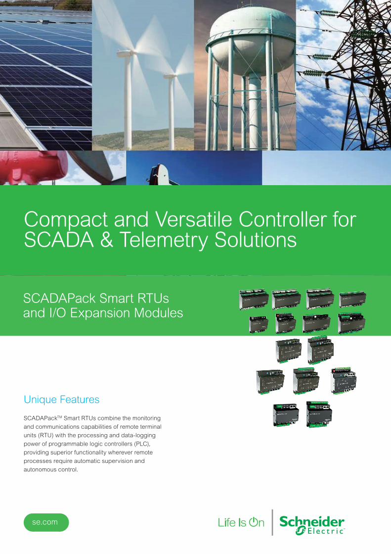
Multiple Applications - SCADAPack x70Oil and Gas:• Tank monitoring and automation• Well test automation• Well production and optimization• Measurement
Water & Wastewater• Leakage detection• Equipment monitoring & control• Water quality monitoring• Irrigation• DMAs (District Metering Areas), PMAs (Press. Monitoring Areas)• Monitoring flow / level / pressure and temperature, etc.• and many others...
Life is On | Schneider Electric 5
SCADAPack
RTU
Analog
Input1
Analog
Output1
Digital
Input1
Digital
Output1
Frequency
Input1
Serial
Port
Ethernet
Port
USB
Device
Port
USB Host
Port
470 4 0 4 24 (shared
with DIs)5 2 1 1
474 12 2 20 128 (shared
with DIs5 2 1 1
570 0 0 2 1 0 4 3 1 1
575 6 2 (option) 18 98 (shared
with DIs)4 3 1 1
574 8 2 (option) 18 11 0 4 3 1 1
Footnote:1 Number of on-board I/O may be further expanded for any SCADAPack using Expansion I/O Modules. Refer to individual product data sheets for detailed
specifications.

SCADAPack 32: P4A | P4 | P4B Specifications
P4A, integrated 5604 I/O board
Controller
Processor Hitachi SH-3 32-bit CMOS microcontroller, 120 MHz clock, integrated watchdog timer
Memory 8 Mb SDRAM, 4 Mb FLASH, 1 Mb CMOS RAM
Non-volatile RAM CMOS RAM with lithium battery retains contents for 2 years with no power
I/O
Analog Inputs • 8, user-selectable 0...10 Vdc (15-bit) or 0...20 mA (14-bit)
• 1, 0...32.768 Vdc (10-bit)
Analog Outputs 2 with optional 5305 analog output module, output range 0...20 mA
Digital Inputs 4 on controller board - 3 Digital Input/Counter, 1 Interrupt with optical isolation
Digital Outputs 1, 30 Vdc / 60 mA (used as status output)
Digital I/O 5604 I/O 32 configurable as input or output (1 A DC max output / dry contact input)
Additional I/O
I/O Expansion
Supported modules:
5304, 5401, 5402, 5403, 5404, 5405, 5406A, 5407, 5409, 5410, 5411, 5414, 5415, 5502, 5504, 5505, 5506,
5606, 5607, 5904
Communications
Serial Port COM1 Configurable RS-232 or RS-485, 2-wire half duplex or 4-wire full/half duplex
Serial Port COM2, COM4• RS-232, DTE, 8 -pin modular jack, full or half duplex with RTS/CTS control
• Implemented Td, Rd, CTS, RTS, DCD, DTR, +5 V
Serial Port COM3 Located on 5604 I/O module. Same specifications as COM2 and COM4
Baud Rates COM1,
COM2 & COM4300, 600, 1200, 2400, 4800, 9600, 19200, 38400, 57600 and 115200
Baud Rate COM3 1200, 2400, 4800, 9600, 19200, 38400, 57600 and 115200
Serial Protocols Modbus RTU, Modbus ASCII, DNP3, DF1, PPP
Ethernet Port RJ45, 10BaseT
Network Protocols IP: ARP, TCP, TFTP, UDP, ICMP
Ethernet Port Protocols Modbus/TCP, Modbus RTU in UDP, Modbus ASCII in UDP, DNP in TCP, DNP in UDP
Selection GuideStandard SCADAPack
SCADAPack Smart RTU

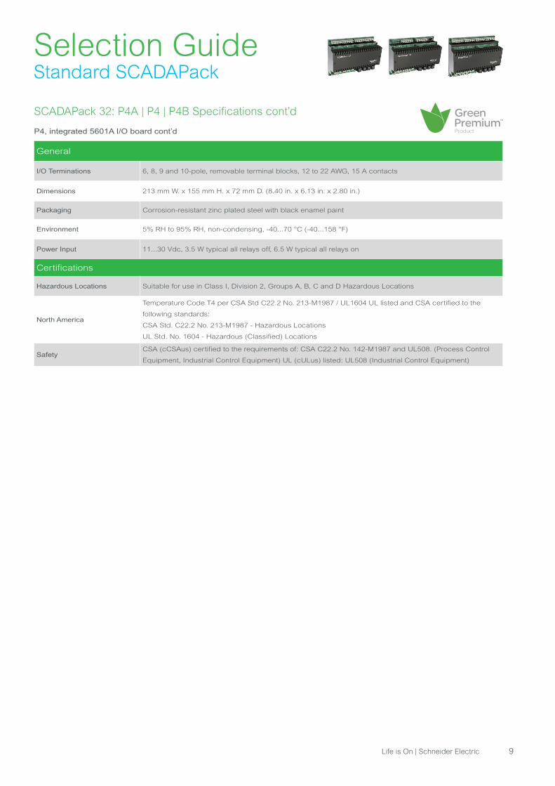
SCADAPack 32: P4A | P4 | P4B Specifications cont’d
P4A, integrated 5604 I/O board cont’d
General
I/O Terminations 6, 8, 9 and 10-pole, removable terminal blocks, 12 to 22 AWG, 15 A contacts
Dimensions 213 mm W. x 155 mm H. x 72 mm D. (8.40 in. x 6.13 in. x 2.80 in.)
Packaging Corrosion-resistant zinc plated steel with black enamel paint
Environment 5% RH to 95% RH, non-condensing, -40...70 °C (-40...158 °F)
Power Input 11...30 Vdc, 4.3 W typical (10.8 W full I/O capacity in use)
Certifications
Hazardous Locations Suitable for use in Class I, Division 2, Groups A, B, C and D Hazardous Locations
North America
Temperature Code T4 per CSA Std C22.2 No. 213-M1987 / UL1604 UL listed and CSA certified to the
following standards:
• CSA Std. C22.2 No. 213-M1987 - Hazardous Locations
• UL Std. No. 1604 - Hazardous (Classified) Locations
SafetyCSA (cCSAus) certified to the requirements of: CSA C22.2 No. 142-M1987 and UL508. (Process Control
Equipment, Industrial Control Equipment) UL (cULus) listed: UL508 (Industrial Control Equipment)
Selection GuideStandard SCADAPack
Life is On | Schneider Electric 7
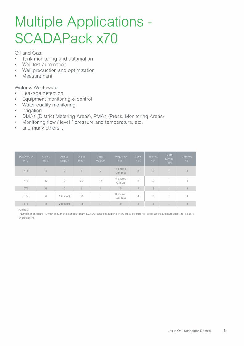
SCADAPack 32: P4A | P4 | P4B Specifications cont’d
P4, integrated 5601A I/O board
Controller
Processor Hitachi SH-3 32-bit CMOS microcontroller, 120 MHz clock, integrated watchdog timer
Memory 8 Mb SDRAM, 4 Mb FLASH, 1 Mb CMOS RAM
Non-volatile RAM CMOS RAM with lithium battery retains contents for 2 years with no power
I/O
Analog Inputs 8, user-selectable 0...5 Vdc (15-bit) or 0...20 mA (14-bit)
Analog Outputs 2 with optional 5303 analog output module, output range 0...20 mA
Digital Inputs• 4 on controller board - 3 Digital Input/Counter, 1 Interrupt with optical isolation
• 16 on 5601A I/O module - 6.5 mA typical at 24 Vdc and 3.5 mA typical at 115 V
Digital Outputs
• 1 on controller board , 30 Vdc, 60 mA (used as status output)
• 12 on 5601A I/O module - Sealed mechanical relay:
• 0.4 A at 125 Vrms, 2 A at 30 Vdc resistive loads
• 1.0 A at 30 Vdc, 0.2 A at 125 Vrms inductive load with pf=0.4, L/R=7 ms
• 250 Vrms, 220 Vdc maximum operating voltage
Additional I/O
I/O Expansion
Supported modules:
5304, 5401, 5402, 5403, 5404, 5405, 5406A, 5407, 5409, 5410, 5411, 5414, 5415, 5502, 5504, 5505, 5506,
5606, 5607, 5904
Communications
Serial Port COM1 Configurable RS-232 or RS-485, 2 wire half duplex or 4 wire full/half duplex
Serial Ports COM2,
COM4
RS-232, DTE, 8 -pin modular jack, full or half duplex with RTS/CTS control. Implemented Td, Rd, CTS, RTS,
DCD, DTR, +5 Vdc
Serial Port COM3 Located on 5601A I/O module. Same specifications as COM2 and COM4
Baud Rates COM1,
COM2 & COM4300, 600, 1200, 2400, 4800, 9600, 19200, 38400, 57600 and 115200
Baud Rate COM3 1200, 2400, 4800, 9600, 19200, 38400, 57600 and 115200
Serial Protocols Modbus/RTU, Modbus ASCII, DNP3, DF1, PPP
Ethernet Port 10BaseT, RJ45
Network Protocols IP: ARP, TCP, TFTP, UDP, ICMP
Ethernet Port Protocols Modbus TCP, Modbus RTU in UDP, Modbus ASCII in UDP, DNP in TCP, DNP in UDP
Selection GuideStandard SCADAPack
SCADAPack Smart RTU
SCADAPack 32: P4A | P4 | P4B Specifications cont’d
P4, integrated 5601A I/O board cont’d
General
I/O Terminations 6, 8, 9 and 10-pole, removable terminal blocks, 12 to 22 AWG, 15 A contacts
Dimensions 213 mm W. x 155 mm H. x 72 mm D. (8.40 in. x 6.13 in. x 2.80 in.)
Packaging Corrosion-resistant zinc plated steel with black enamel paint
Environment 5% RH to 95% RH, non-condensing, -40...70 °C (-40...158 °F)
Power Input 11...30 Vdc, 3.5 W typical all relays off, 6.5 W typical all relays on
Certifications
Hazardous Locations Suitable for use in Class I, Division 2, Groups A, B, C and D Hazardous Locations
North America
Temperature Code T4 per CSA Std C22.2 No. 213-M1987 / UL1604 UL listed and CSA certified to the
following standards:
CSA Std. C22.2 No. 213-M1987 - Hazardous Locations
UL Std. No. 1604 - Hazardous (Classified) Locations
SafetyCSA (cCSAus) certified to the requirements of: CSA C22.2 No. 142-M1987 and UL508. (Process Control
Equipment, Industrial Control Equipment) UL (cULus) listed: UL508 (Industrial Control Equipment)
Selection GuideStandard SCADAPack
Life is On | Schneider Electric 9

SCADAPack 32: P4A | P4 | P4B Specifications cont’d
P4B, integrated 5606 I/O board
Controller
Processor Hitachi SH-3 32-bit CMOS microcontroller, 120 MHz clock, integrated watchdog timer
Memory 8 Mb SDRAM, 4 Mb FLASH, 1 Mb CMOS RAM
Non-volatile RAM CMOS RAM with lithium battery retains contents for 2 years with no power
I/O
Analog Inputs8, single-ended, software selectable 0...5 Vdc / 0...10 Vdc or 0...20 mA / 4...20 mA
(15-bit resolution)
Analog Outputs 2 with optional 5305 analog output module, output range 0...20 mA
Digital Inputs
4 on controller board - 3 Digital Input/Counter, 1 Interrupt with optical isolation
32 on 5606 I/O module
• 0.67 mA typical at 24 Vdc on the 12/24 Vdc range
• 0.37 mA typical at 48 Vdc on the 48 Vdc range
• 0.35 mA typical at 120 Vdc on the 115/125 Vdc range
• 0.35 mA typical at 240 Vdc on the 240 Vdc range
Digital Outputs
1 on controller board , 30 Vdc, 60 mA (used as status output)
16 relay outputs on 5606 I/O module - dry contact or DC solid state:
• Dry contact rating: 3 A, 30 Vdc or 240 Vac (Resistive)
• DC solid state rating: 3 A, 60 Vdc
Additional I/O
I/O Expansion
Supported modules:
5304, 5401, 5402, 5403, 5404, 5405, 5406A, 5407, 5409, 5410, 5411, 5414, 5415, 5502, 5504, 5505, 5506,
5606, 5607, 5904
Communications
Serial Port COM1 Configurable RS-232 or RS-485, 2 wire half duplex or 4 wire full/half duplex
Serial Ports COM2,
COM4
RS-232, DTE, 8-pin modular jack, full or half duplex with RTS/CTS control. Implemented Td, Rd, CTS, RTS,
DCD, DTR, +5 Vdc
Baud Rates COM1,
COM2 & COM4300, 600, 1200, 2400, 4800, 9600, 19200, 38400, 57600 and 115200
Serial Protocols Modbus RTU, Modbus ASCII, DNP3, DF1, PPP
Ethernet Port 10BaseT, RJ45
Network Protocols IP: ARP, TCP, TFTP, UDP, ICMP
Ethernet Port Protocols Modbus TCP, Modbus RTU in UDP, Modbus ASCII in UDP, DNP in TCP, DNP in UDP
Selection GuideStandard SCADAPack
SCADAPack Smart RTU

SCADAPack 32: P4A | P4 | P4B Specifications cont’d
P4B, integrated 5606 I/O board cont’d
General
I/O Terminations 5, 6, 8, 9 and 10-pole, removable terminal blocks, 12 to 22 AWG, 15 A contacts
Dimensions 213 mm W. x 164 mm H. x 72 mm D. (8.40 in. x 6.48 in. x 2.80 in.)
Packaging Corrosion-resistant zinc plated steel with black enamel paint
Environment 5% RH to 95% RH, non-condensing, -40...70 °C (-40...158 °F)
Power Input 11...30 Vdc, 4.3 W typical (10.8 W full I/O capacity in use)
Certifications
Hazardous Locations Suitable for use in Class I, Division 2, Groups A, B, C and D Hazardous Locations
North America
Temperature Code T4 per CSA Std C22.2 No. 213-M1987 / UL1604 UL listed and CSA certified to the
following standards:
• CSA Std. C22.2 No. 213-M1987 - Hazardous Locations
• UL Std. No. 1604 - Hazardous (Classified) Locations
Hazardous Locations EuropeModel “5606 SSR, 24DI version only” ATEX II 3G, Ex nA IIC T4 per EN 60079-15, protection type n (Zone
2). Does not include Wireless versions
Hazardous LocationsModel “5606 SSR version only” IECEx, Ex nA IIC T4 per IEC 60079-15, protection type n (Zone 2) Does not
include Wireless versions
SafetyCSA (cCSAus) certified to the requirements of: CSA C22.2 No. 142-M1987 and UL508. (Process Control
Equipment, Industrial Control Equipment) UL (cULus) listed: UL508 (Industrial Control Equipment)
Selection GuideStandard SCADAPack
Life is On | Schneider Electric 11
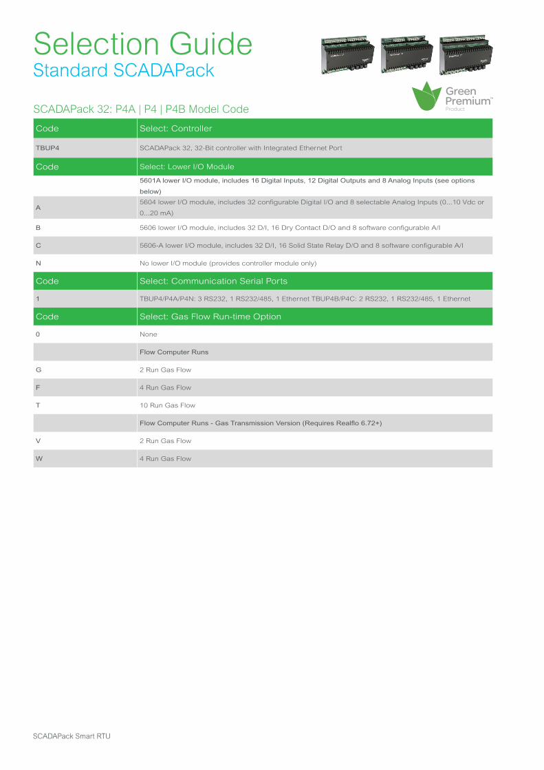
SCADAPack 32: P4A | P4 | P4B Model Code
Code Select: Controller
TBUP4 SCADAPack 32, 32-Bit controller with Integrated Ethernet Port
Code Select: Lower I/O Module
5601A lower I/O module, includes 16 Digital Inputs, 12 Digital Outputs and 8 Analog Inputs (see options
below)
A5604 lower I/O module, includes 32 configurable Digital I/O and 8 selectable Analog Inputs (0...10 Vdc or
0...20 mA)
B 5606 lower I/O module, includes 32 D/I, 16 Dry Contact D/O and 8 software configurable A/I
C 5606-A lower I/O module, includes 32 D/I, 16 Solid State Relay D/O and 8 software configurable A/I
N No lower I/O module (provides controller module only)
Code Select: Communication Serial Ports
1 TBUP4/P4A/P4N: 3 RS232, 1 RS232/485, 1 Ethernet TBUP4B/P4C: 2 RS232, 1 RS232/485, 1 Ethernet
Code Select: Gas Flow Run-time Option
0 None
Flow Computer Runs
G 2 Run Gas Flow
F 4 Run Gas Flow
T 10 Run Gas Flow
Flow Computer Runs - Gas Transmission Version (Requires Realflo 6.72+)
V 2 Run Gas Flow
W 4 Run Gas Flow
Selection GuideStandard SCADAPack
SCADAPack Smart RTU

SCADAPack 32: P4A | P4 | P4B Model Code cont’d
Code Select: Protocol Option/Programming Environment
2Modbus and DNP 3.0 (Level 2) protocol with Telepace Ladder Logic and C Language
firmware loaded - IEC enabled
5Modbus and DNP 3.0 (Level 2) protocol with IEC 61131-3 and C Language firmware loaded - Telepace
enabled
Code Select: Analog Inputs
010...20 mA, Single-ended (On TBUP4 & TBUP4A, Default on TBUP4B which is software
configurable to 0...5 Vdc or 0...10 Vdc)
02 0...5 Vdc, Single-ended (TBUP4 Only)
03 0...10 Vdc, Single-ended (TBUP4A Only)
Code Select: Digital Inputs/Outputs
0 Dry Contact Digital Inputs, Open Drain Digital Outputs, Individually configurable (TBUP4A Only)
024 Vdc D/I TBUP4 & TBUP4B: Dry Contact D/O TBUP4C: Solid State Relay D/O (Not for TBUP4A or TBU-
P4N)
1120 Vac D/I TBUP4 & TBUP4B: Dry Contact D/O TBUP4C: Solid State Relay D/O (Not for TBUP4A or TBU-
P4N)
Code Select: Analog Outputs
0 None (required for TBUP4N)
1 2 channel Analog Output option, 0...20 mA
Footnotes:
1. Available only with optional integrated wireless modules or with stand-alone wireless modules.
2. Not applicable in all countries.
Note: This product is RoHS-compliant.
Selection GuideStandard SCADAPack
Life is On | Schneider Electric 13
Selection GuideStandard SCADAPack
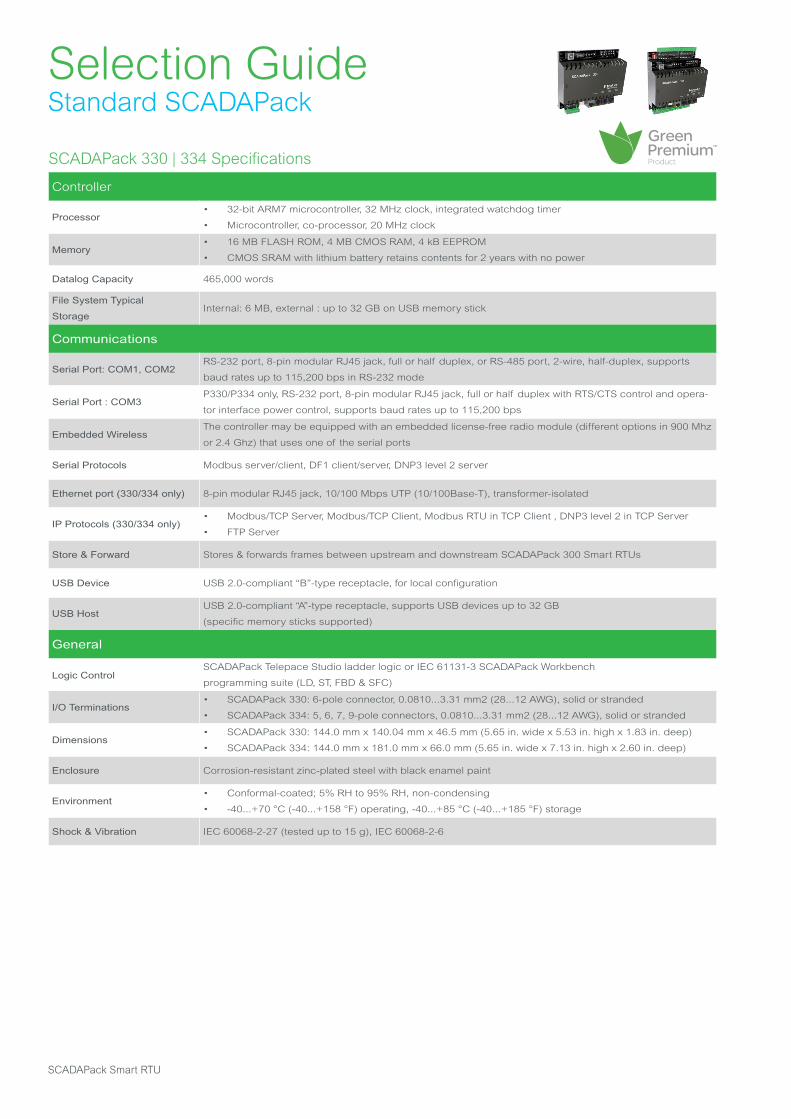
SCADAPack 330 | 334 Specifications
Controller
Processor• 32-bit ARM7 microcontroller, 32 MHz clock, integrated watchdog timer
• Microcontroller, co-processor, 20 MHz clock
Memory• 16 MB FLASH ROM, 4 MB CMOS RAM, 4 kB EEPROM
• CMOS SRAM with lithium battery retains contents for 2 years with no power
Datalog Capacity 465,000 words
File System Typical
Storage Internal: 6 MB, external : up to 32 GB on USB memory stick
Communications
Serial Port: COM1, COM2RS-232 port, 8-pin modular RJ45 jack, full or half duplex, or RS-485 port, 2-wire, half-duplex, supports
baud rates up to 115,200 bps in RS-232 mode
Serial Port : COM3P330/P334 only, RS-232 port, 8-pin modular RJ45 jack, full or half duplex with RTS/CTS control and opera-
tor interface power control, supports baud rates up to 115,200 bps
Embedded WirelessThe controller may be equipped with an embedded license-free radio module (different options in 900 Mhz
or 2.4 Ghz) that uses one of the serial ports
Serial Protocols Modbus server/client, DF1 client/server, DNP3 level 2 server
Ethernet port (330/334 only) 8-pin modular RJ45 jack, 10/100 Mbps UTP (10/100Base-T), transformer-isolated
IP Protocols (330/334 only)• Modbus/TCP Server, Modbus/TCP Client, Modbus RTU in TCP Client , DNP3 level 2 in TCP Server
• FTP Server
Store & Forward Stores & forwards frames between upstream and downstream SCADAPack 300 Smart RTUs
USB Device USB 2.0-compliant “B”-type receptacle, for local configuration
USB HostUSB 2.0-compliant “A”-type receptacle, supports USB devices up to 32 GB
(specific memory sticks supported)
General
Logic Control SCADAPack Telepace Studio ladder logic or IEC 61131-3 SCADAPack Workbench
programming suite (LD, ST, FBD & SFC)
I/O Terminations • SCADAPack 330: 6-pole connector, 0.0810...3.31 mm2 (28...12 AWG), solid or stranded
• SCADAPack 334: 5, 6, 7, 9-pole connectors, 0.0810...3.31 mm2 (28...12 AWG), solid or stranded
Dimensions• SCADAPack 330: 144.0 mm x 140.04 mm x 46.5 mm (5.65 in. wide x 5.53 in. high x 1.83 in. deep)
• SCADAPack 334: 144.0 mm x 181.0 mm x 66.0 mm (5.65 in. wide x 7.13 in. high x 2.60 in. deep)
Enclosure Corrosion-resistant zinc-plated steel with black enamel paint
Environment• Conformal-coated; 5% RH to 95% RH, non-condensing
• -40...+70 °C (-40...+158 °F) operating, -40...+85 °C (-40...+185 °F) storage
Shock & Vibration IEC 60068-2-27 (tested up to 15 g), IEC 60068-2-6
SCADAPack Smart RTU

Selection GuideStandard SCADAPack
SCADAPack 330 | 334 Specifications cont’d
Power Supply
Rated Voltage 12...30 Vdc. Limit voltage: 11.5...32 Vdc; turn on voltage: 10...11.5 Vdc; turn off voltage: 9...10 Vdc
Maximum Power 7 W at 24 Vdc (internal 5 Vdc supply fully loaded)
Power Requirements
SCADAPack 330 and 334 support 3 power modes: sleep, normal clock speed and reduced
clock speed
• Typical power consumption (at 20 °C/ 68 °F):
At normal
clock speed
At reduced
clock speed
SCADAPack
Model
Ethernet/
USB
DO
Relays12 V dc 24 V dc 12 V dc 24 V dc
Sleep Mode 80 mW 240 mW 80 mW 240 mW
330OFF 0.7 W 0.9 W 0.5 W 0.7 W
ON - 1.8 W 2.0 W 1.6 W 1.8 W
334
OFF 0.9 W 1.2 W 0.7 W 1.0 W
OFF ON 2.9 W 3.4 W 2.7 W 3.2 W
ON OFF 2.4 W 2.8 W 2.3 W 2.6 W
ON 4.0 W 4.5 W 3.8 W 4.3 W
Certifications
EMC and Radio
Frequency
• ICES-003 Issue 5 August 2012
• CE and RCM markings
General Safety UL 508
Hazardous LocationscCSAus Non-incendive Electrical Equipment for use in Class I, Division 2, Groups A, B, C and D
IECEx/ATEX Class I, Zone 2
Life is On | Schneider Electric 15

Selection GuideStandard SCADAPack
SCADAPack 330 | 334 Specifications cont'd
Controller Board
Counter Inputs• 1, 0...10 Hz (dry contact)
• 2, 0...10 kHz (turbine or dry contact)
Internal Power Monitor Power input - analog input and low indication, onboard lithium battery - low indication
Internal Temperature
MonitorController temperature range -40...+75 °C (-40...+167 °F)
I/O board (334 only)
Analog Inputs
8, software-configurable to 0...20, 4...20 mA , 0...5 or 0...10 V, plus over range
• Resolution: 15-bit ADC (15-bit over the measurement range in 10 V, 14-bit in 20 mA)
• Accuracy: ±0.1% of full scale at 25 °C (77 °F), ±0. 2% over temperature range
• Input Resistance: 250 Ω or 20 kΩ in 20 mA or 10 V configurations (60 kΩ for 32.768 V)
• Normal rejection mode: 27 dB at 60 Hz
• Sampling rate: 170 ms
• Isolation: 500 Vac from logic and chassis
Analog Outputs• 2 (optional), 0...20/4...20 mA, voltage output may be accomplished with external precision resistor
• Same features as the analog outputs located on the controller board
Digital Inputs
16, 12…24 Vdc
• Turn on voltage: 9 Vdc (minimum), Turn off voltage: 4 Vdc (maximum)
• Over-voltage tolerance: 150% sustained over-voltage without foreseeable damage
• DC input current: 0.67 mA at 24 Vdc
• Time stamping : 170 ms
• Isolation: in group of 8, 1500 Vac from logic supply and chassis
Digital Outputs
10, dry-contact relays or solid-state relays (Form A - normally open)
• 5 contacts share one common
• Isolation: Chassis or logic to contact 1500 Vac (1 min.)
Dry-contact relays:
• Contact rating 3 A, 30 Vdc (resistive), 12 A maximum per common
Solid state relays:
• Load voltage 60 Vdc maximum
• Load current 3 A continuous max at 50 °C (122 °F) or 2 A at 70 °C (158 °F)
Additional IO
I/O Expansion
Supported modules:
• Current 5000 modules
Maximum number of modules per unit:
• SCADAPack 330: 8 (*)
• SCADAPack 334: 7 (*)
(*): to reach this limit, additional power supply modules (reference: 5103) are required
SCADAPack Smart RTU
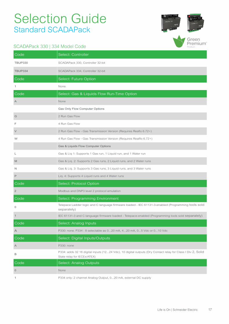
SCADAPack 330 | 334 Model Code
Code Select: Controller
TBUP330 SCADAPack 330, Controller 32-bit
TBUP334 SCADAPack 334, Controller 32-bit
Code Select: Future Option
1 None
Code Select: Gas & Liquids Flow Run-Time Option
A None
Gas Only Flow Computer Options
G 2 Run Gas Flow
F 4 Run Gas Flow
V 2 Run Gas Flow - Gas Transmission Version (Requires Reaflo 6.72+)
W 4 Run Gas Flow - Gas Transmission Version (Requires Realflo 6.72+)
Gas & Liquids Flow Computer Options
L Gas & Liq 1: Supports 1 Gas run, 1 Liquid run, and 1 Water run
M Gas & Liq. 2: Supports 2 Gas runs, 2 Liquid runs, and 2 Water runs
N Gas & Liq. 3: Supports 3 Gas runs, 3 Liquid runs, and 3 Water runs
P Liq. 4: Supports 4 Liquid runs and 4 Water runs
Code Select: Protocol Option
2 Modbus and DNP3 level 2 protocol emulation
Code Select: Programming Environment
0Telepace Ladder logic and C language firmware loaded - IEC 61131-3-enabled (Programming tools sold
separately)
1 IEC 61131-3 and C language firmware loaded - Telepace-enabled (Programming tools sold separately)
Code Select: Analog Inputs
A P330: none. P334 : 8 selectable as 0...20 mA, 4...20 mA, 0...5 Vdc or 0...10 Vdc
Code Select: Digital Inputs/Outputs
A P330: none
BP334: adds 32 16 digital inputs (12...24 Vdc), 10 digital outputs (Dry Contact relay for Class I Div 2, Solid
State relay for IECEx/ATEX)
Code Select: Analog Outputs
0 None
1 P334 only: 2 channel Analog Output, 0...20 mA, external DC supply
Selection GuideStandard SCADAPack
Life is On | Schneider Electric 17

SCADAPack 330 | 334 Model Code cont’d
Code Select: Future Option
0 None
Code Select: Certifications
S With FCC, UL508, CE marking and RCM
X Adds IECEx/ATEX Class I, Zone 2
U Adds cCSAus Nonincendive Electrical Equipment for use in Class I, Division 2, Groups A, B, C and D
Selection GuideStandard SCADAPack
SCADAPack Smart RTU

Selection GuideStandard SCADAPack
SCADAPack 350 | 357 Specifications
Controller
Processor• 32-bit ARM7 microcontroller, 32 MHz clock, integrated watchdog timer
• Microcontroller, co-processor, 20 MHz clock
Memory• 16 MB FLASH ROM, 4 MB CMOS RAM, 4 kB EEPROM
• CMOS SRAM with lithium battery retains contents for 2 years with no power
Datalog Capacity 465,000 words
File System Typical
Storage Internal: 6 MB, external : up to 32 GB on USB memory stick
Communications
Serial Port: COM1, COM2
• RS-485, 2-pole removable terminal block, 2-wire, half duplex, supports baud rates up to 115,200
bps
• RS-232 port, 8-pin modular RJ45 jack, full or half duplex, or RS-485 port, 2-wire, half-duplex,
supports baud rates up to 115,200 bps in RS-232 mode
Serial Port : COM3RS-232 port, 8-pin modular RJ45 jack, full or half duplex with RTS/CTS control and operator interface pow-
er control, supports baud rates up to 115,200 bps
Serial Protocols Modbus client/server, DF1 client/server, DNP3 level 2 server
Ethernet Port 8-pin modular RJ45 jack, 10/100 Mbps UTP (10/100 Base-T), transformer-isolated
IP Protocols• Modbus/TCP Server, Modbus/TCP Client, Modbus RTU in TCP Client , DNP3 level 2 in TCP Server
• FTP Server
Store & Forward Stores & forwards frames between upstream and downstream SCADAPack 300 Smart RTUs
USB Device USB 2.0-compliant “B”-type receptacle, for local configuration
USB HostUSB 2.0-compliant “A”-type receptacle, supports USB devices up to 32 GB (specific memory sticks
supported)
General
Logic Control SCADAPack Telepace Studio ladder logic or IEC 61131-3 SCADAPack Workbench
programming suite: (LD, ST, FBD & SFC)
I/O Terminations
• SCADAPack 350: 6, 12-pole connector, 0.0810...3.31 mm2 (28...12 AWG), solid or stranded
• SCADAPack 357: 5, 6, 7, 9, 10, 12-pole connectors, 0.0810...3.31 mm2 (28...12 AWG), solid or
stranded
Dimensions• SCADAPack 350: 211.8 mm x 140.4 mm x 46.5 mm (8.34 in. wide x 5.53 in. high x 1.83 in. deep)
• SCADAPack 357: 211.8 mm x 181.0 mm x 66.0 mm (8.34 in. wide x 7.13 in. high x 2.60 in. deep)
Enclosure Corrosion-resistant zinc-plated steel with black enamel paint
Environment
• Conformal coated
• -40...+70 °C (-40...+158 °F) operating, -40...+85 °C (-40...185 °F) storage
• 5% RH to 95% RH, non-condensing
Shock & Vibration IEC 60068-2-27 (tested up to 15 g), IEC 60068-2-6
Life is On | Schneider Electric 19
Selection GuideStandard SCADAPack
SCADAPack 350 | 357 Specifications cont'd
Power Supply
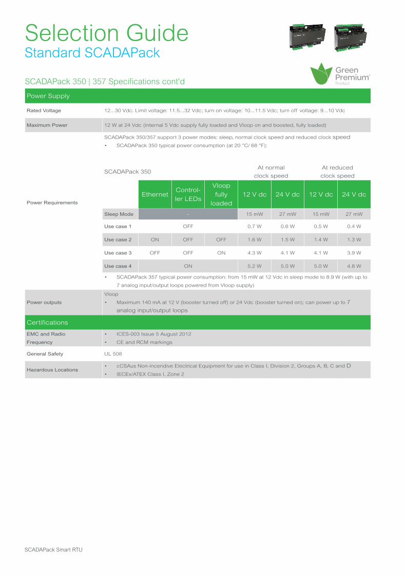
Rated Voltage 12...30 Vdc. Limit voltage: 11.5...32 Vdc; turn on voltage: 10...11.5 Vdc; turn off voltage: 9...10 Vdc
Maximum Power 12 W at 24 Vdc (internal 5 Vdc supply fully loaded and Vloop on and boosted, fully loaded)
Power Requirements
SCADAPack 350/357 support 3 power modes: sleep, normal clock speed and reduced clock speed
• SCADAPack 350 typical power consumption (at 20 °C/ 68 °F):
SCADAPack 350At normal
clock speed
At reduced
clock speed
EthernetControl-
ler LEDs
Vloop
fully
loaded
12 V dc 24 V dc 12 V dc 24 V dc
Sleep Mode - 15 mW 27 mW 15 mW 27 mW
Use case 1 OFF 0.7 W 0.6 W 0.5 W 0.4 W
Use case 2 ON OFF OFF 1.6 W 1.5 W 1.4 W 1.3 W
Use case 3 OFF OFF ON 4.3 W 4.1 W 4.1 W 3.9 W
Use case 4 ON 5.2 W 5.0 W 5.0 W 4.8 W
• SCADAPack 357 typical power consumption: from 15 mW at 12 Vdc in sleep mode to 8.9 W (with up to
7 analog input/output loops powered from Vloop supply)
Power outputs
Vloop
• Maximum 140 mA at 12 V (booster turned off) or 24 Vdc (booster turned on); can power up to 7
analog input/output loops
Certifications
EMC and Radio
Frequency
• ICES-003 Issue 5 August 2012
• CE and RCM markings
General Safety UL 508
Hazardous Locations• cCSAus Non-incendive Electrical Equipment for use in Class I, Division 2, Groups A, B, C and D
• IECEx/ATEX Class I, Zone 2
SCADAPack Smart RTU

Selection GuideStandard SCADAPack
SCADAPack 350 | 357 Specifications cont'd
Controller Board
Analog Inputs
5, user-selectable 0...10 V or 0...20 mA plus over range
• 1, 0...32.7 Vdc (15-bit) for DC supply monitoring
• Resolution: 15-bit ADC (15-bit over the measurement range in 10 V, 14-bit in 20 mA)
• Accuracy: ±0.1% of full scale at 25 °C (+77 °F), ±0.2% over temperature range
• Input Resistance: 250 Ω or 20 kΩ in 20 mA or 10 V configurations (60 kΩ for 32.768 V)
• Normal rejection mode: 27 dB at 60 Hz
Analog Outputs
2 (optional), 0...20 mA, 4...20 mA, voltage output may be accomplished with external precision resistor
• Resolution: 12-bit over 0...20 mA range
• Accuracy: ±0.15% at 25 °C (+77 °F), ±0.35% of full scale over temperature range
• Response Time: less than 10 μs for 10% to 90% signal change
• Power Supply: 12…30 Vdc, external
• Power (Current) Requirements: 10 mA plus up to 20 mA per output
• Isolation: isolated from RTU logic and chassis
• Load Range: 12 Vdc: 0…375 Ω, 24 Vdc: 0…925 Ω,
• Logic End-Of- Scan to Signal Update Latency: typically 18... 27 ms
Digital Inputs/Outputs
8, user-selectable as inputs or outputs (open drain)
As Digital Inputs
• Dry contact
As Digital Outputs
• Sinking MOSFET output, rated 30 V, 0.5 A, ground return connected to Chassis Ground
Counter Inputs• 1, 0...10 Hz (dry contact)
• 2, 0...10 kHz (turbine or dry contact)
Internal Power monitor Power input - analog input and low indication, onboard lithium battery - low indication
Internal Temperature Monitor Controller temperature range -40 °C...+75 °C (-40...+167 °F)
I/O board (357 only)
Analog Inputs
8, software-configurable to 0...20, 4...20 mA , 0...5 or 0...10 V
Same features as for the 5 analog inputs located on the controller board (see above) except the following:
• Isolation: 500 Vac from logic and chassis
Analog Outputs2 (optional), 0...20/4...20 mA, voltage output may be accomplished with external precision resistor.
Same features as for the analog outputs located on the controller board
Digital Inputs
32, 12…24 Vdc
• Turn on voltage: 9 Vdc (minimum), Turn off voltage: 4 Vdc (maximum)
• Over-voltage tolerance: 150% sustained over-voltage without foreseeable damage
• DC input current: 0.67 mA at 24 Vdc
• Time stamping : 170 ms
• Isolation : in group of 8, 1500 Vac from logic supply and chassis
Digital Outputs
16, relays (Form A)
• 4 contacts share one common
• Isolation : isolated in groups of 4. Isolated from RTU logic, RTU chassis and other groups to 1500
Vac
• Contact Rating: 3 A, 30 Vdc
Life is On | Schneider Electric 21
Selection GuideStandard SCADAPack
SCADAPack 350 | 357 Specifications cont'd
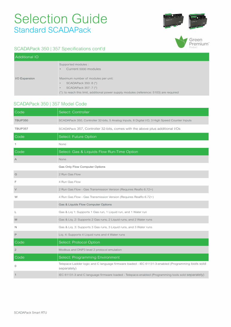
Additional IO
I/O Expansion
Supported modules :
• Current 5000 modules
Maximum number of modules per unit:
• SCADAPack 350: 8 (*)
• SCADAPack 357: 7 (*)
(*): to reach this limit, additional power supply modules (reference: 5103) are required
SCADAPack 350 | 357 Model Code
Code Select: Controller
TBUP350 SCADAPack 350, Controller 32-bits, 5 Analog Inputs, 8 Digital I/O, 3 High Speed Counter Inputs
TBUP357 SCADAPack 357, Controller 32-bits, comes with the above plus additional I/Os
Code Select: Future Option
1 None
Code Select: Gas & Liquids Flow Run-Time Option
A None
Gas Only Flow Computer Options
G 2 Run Gas Flow
F 4 Run Gas Flow
V 2 Run Gas Flow - Gas Transmission Version (Requires Reaflo 6.72+)
W 4 Run Gas Flow - Gas Transmission Version (Requires Realflo 6.72+)
Gas & Liquids Flow Computer Options
L Gas & Liq 1: Supports 1 Gas run, 1 Liquid run, and 1 Water run
M Gas & Liq. 2: Supports 2 Gas runs, 2 Liquid runs, and 2 Water runs
N Gas & Liq. 3: Supports 3 Gas runs, 3 Liquid runs, and 3 Water runs
P Liq. 4: Supports 4 Liquid runs and 4 Water runs
Code Select: Protocol Option
2 Modbus and DNP3 level 2 protocol emulation
Code Select: Programming Environment
0Telepace Ladder logic and C language firmware loaded - IEC 61131-3-enabled (Programming tools sold
separately)
1 IEC 61131-3 and C language firmware loaded - Telepace-enabled (Programming tools sold separately)
SCADAPack Smart RTU
Selection GuideStandard SCADAPack
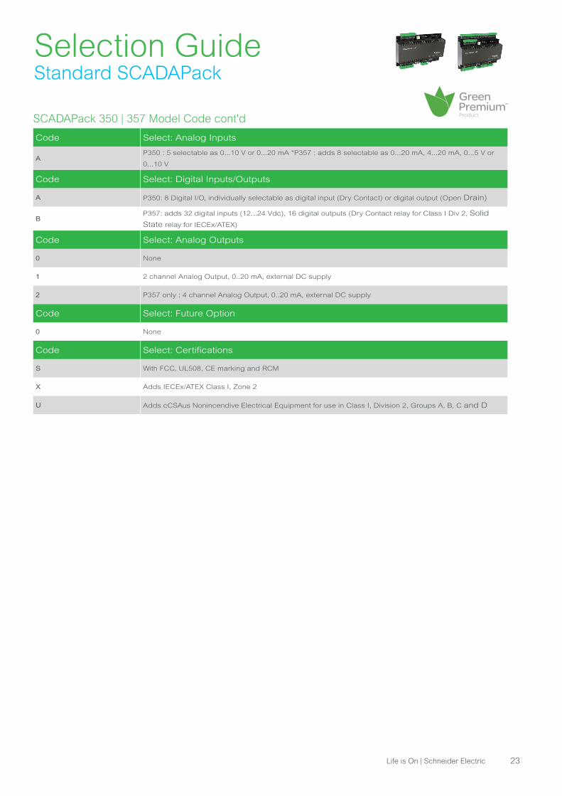
SCADAPack 350 | 357 Model Code cont'd
Code Select: Analog Inputs
AP350 : 5 selectable as 0...10 V or 0...20 mA *P357 : adds 8 selectable as 0...20 mA, 4...20 mA, 0...5 V or
0...10 V
Code Select: Digital Inputs/Outputs
A P350: 8 Digital I/O, individually selectable as digital input (Dry Contact) or digital output (Open Drain)
BP357: adds 32 digital inputs (12...24 Vdc), 16 digital outputs (Dry Contact relay for Class I Div 2, Solid
State relay for IECEx/ATEX)
Code Select: Analog Outputs
0 None
1 2 channel Analog Output, 0..20 mA, external DC supply
2 P357 only : 4 channel Analog Output, 0..20 mA, external DC supply
Code Select: Future Option
0 None
Code Select: Certifications
S With FCC, UL508, CE marking and RCM
X Adds IECEx/ATEX Class I, Zone 2
U Adds cCSAus Nonincendive Electrical Equipment for use in Class I, Division 2, Groups A, B, C and D
Life is On | Schneider Electric 23
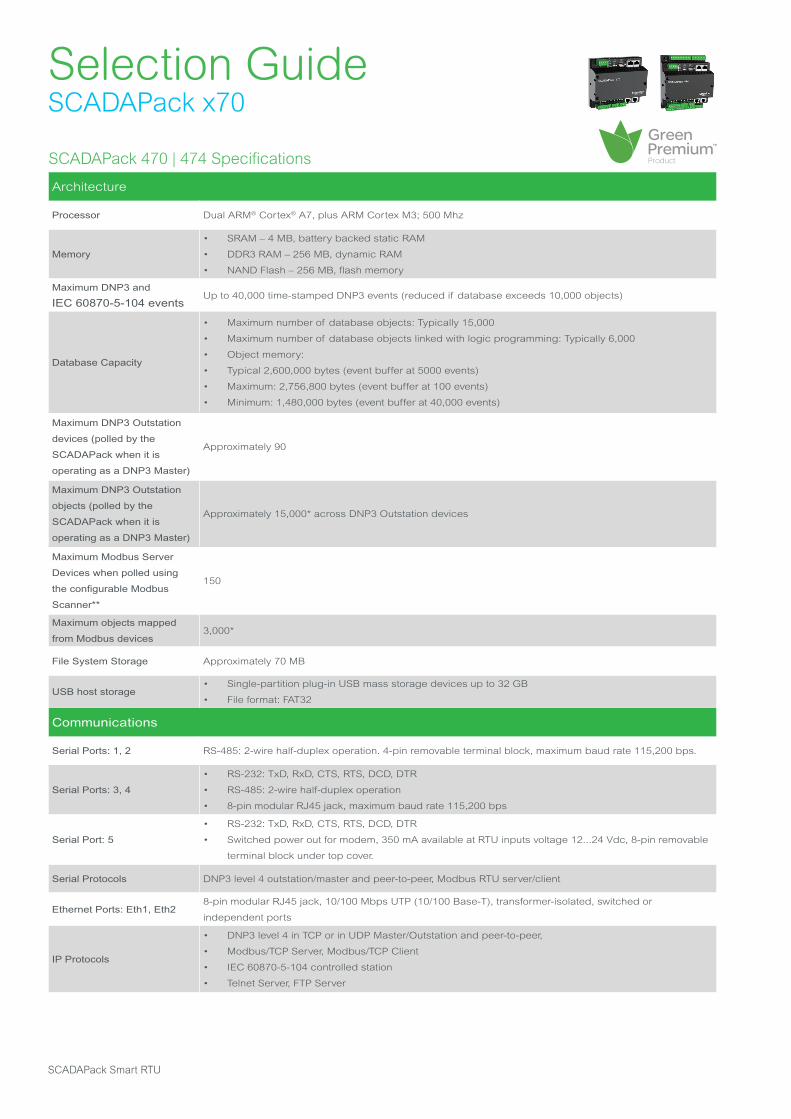
SCADAPack 470 | 474 Specifications
Architecture
Processor Dual ARM® Cortex® A7, plus ARM Cortex M3; 500 Mhz
Memory
• SRAM – 4 MB, battery backed static RAM
• DDR3 RAM – 256 MB, dynamic RAM
• NAND Flash – 256 MB, flash memory
Maximum DNP3 and
IEC 60870-5-104 eventsUp to 40,000 time-stamped DNP3 events (reduced if database exceeds 10,000 objects)
Database Capacity
• Maximum number of database objects: Typically 15,000
• Maximum number of database objects linked with logic programming: Typically 6,000
• Object memory:
• Typical 2,600,000 bytes (event buffer at 5000 events)
• Maximum: 2,756,800 bytes (event buffer at 100 events)
• Minimum: 1,480,000 bytes (event buffer at 40,000 events)
Maximum DNP3 Outstation
devices (polled by the
SCADAPack when it is
operating as a DNP3 Master)
Approximately 90
Maximum DNP3 Outstation
objects (polled by the
SCADAPack when it is
operating as a DNP3 Master)
Approximately 15,000* across DNP3 Outstation devices
Maximum Modbus Server
Devices when polled using
the configurable Modbus
Scanner**
150
Maximum objects mapped
from Modbus devices3,000*
File System Storage Approximately 70 MB
USB host storage• Single-partition plug-in USB mass storage devices up to 32 GB
• File format: FAT32
Communications
Serial Ports: 1, 2 RS-485: 2-wire half-duplex operation. 4-pin removable terminal block, maximum baud rate 115,200 bps.
Serial Ports: 3, 4
• RS-232: TxD, RxD, CTS, RTS, DCD, DTR
• RS-485: 2-wire half-duplex operation
• 8-pin modular RJ45 jack, maximum baud rate 115,200 bps
Serial Port: 5
• RS-232: TxD, RxD, CTS, RTS, DCD, DTR
• Switched power out for modem, 350 mA available at RTU inputs voltage 12...24 Vdc, 8-pin removable
terminal block under top cover.
Serial Protocols DNP3 level 4 outstation/master and peer-to-peer, Modbus RTU server/client
Ethernet Ports: Eth1, Eth28-pin modular RJ45 jack, 10/100 Mbps UTP (10/100 Base-T), transformer-isolated, switched or
independent ports
IP Protocols
• DNP3 level 4 in TCP or in UDP Master/Outstation and peer-to-peer,
• Modbus/TCP Server, Modbus/TCP Client
• IEC 60870-5-104 controlled station
• Telnet Server, FTP Server
Selection GuideSCADAPack x70
SCADAPack Smart RTU
General
Logic Control RemoteConnect software (SCADAPack x70 Logic with five IEC 61131-3 languages)
I/O Terminations 3.3...0.08 mm2 (12...28 AWG), solid or stranded
Dimensions• SCADAPack 470: 142 mm W x 127 mm H x 67 mm D (5.59 in. x 5.00 in. x 2.64 in.)
• SCADAPack 474: 142 mm W x 166 mm H x 88 mm D (5.59 in. x 6.54 in. x 3.46 in.)
Packaging• Corrosion-resistant zinc-plated steel with black enamel paint
• Conformal-coated circuit boards
Environment
• -40…70 °C (-40…158 °F) operating temperature when the unit is mounted horizontally on a vertical
surface
• -40…65 °C (-40…149 °F) operating temperature when the unit is mounted in any other position
• -40…85 °C (-40…185 °F) storage temperature
• 5...95% relative humidity, non-condensing
• Pollution Degree 2, Installation Category I, Indoor use
Shock IEC 61131-2 ½ sine, 15 ms, 15 g
Vibration
• IEC 61131-2
• 5...8.4 Hz: Amplitude controlled, 7.0 mm (0.28 in) peak-to-peak
• 8.4...150 Hz: Acceleration controlled, 1.0 g peak
Power Supply
Input voltage
Rated Voltage 14…29 Vdc
• Turn-on 10…11.5 Vdc
• Turn-off 9…10 Vdc
Power requirements• 2.8 W (SCADAPack 470)
• 4 W (SCADAPack 474
Maximum power input
to controller (excluding
modem)
8.4 W8.4 W
Selection GuideSCADAPack x70
SCADAPack 470 | 474 Specifications cont'd
Communications cont'd
USB Device Port • USB 2.0-compliant C-type receptacle
• Supports communications at 1.5 Mb/s and 12 Mb/s
USB Host Port
• USB 2.0-compliant A-type receptacle
• Supports USB mass storage devices up to 32 GB
• Supports communications at 1.5 Mb/s and 12 Mb/s
* Varies depending on object types, event storage, and integrated application memory usage.
** Refer to product manual for details as actual maximum number of Modbus server devices depends on polling method(s) and port
type (serial or Ethernet).
Life is On | Schneider Electric 25
Selection GuideSCADAPack x70
SCADAPack 470 | 474 Specifications cont'd
Certifications
Industrial Standards
Requirements specific to the SCADAPack functional characteristics, immunity, robustness, and safety:
• IEC/EN 61131-2
• CAN/CSA 22.2 No. 61010-1-12 and CAN/CSA 22.2 No. 61010-2-201
• UL 61010-1 and UL 61010-2-201
CE Marking Compliance
• For the latest information regarding product compliance with European Directives for CE marking, refer to the
EU Declaration of Conformity issued for your product at se.com
• For the latest information regarding product compliance with RoHS, WEEE directives and REACH regulation,
visit the Schneider Electric Check a Product portal at https://www.reach.schneider-electric.com
Installation in Classified
Ex Area
• North America: Hazardous locations Class I, Division 2, groups A, B, C, and D, T4 and Class I, Zone 2, T4, -40
°C ≤ Tamb ≤ 70 °C (-40 °F ≤ Tamb ≤ 158 °F) according to CSA C22.2 No. 213-17, UL 12.12.01
• ATEX: EU Directive 2014/34/EU in defined atmosphere Zone 2 ATEX II 3G, Ex ec nC IIC T4 Gc according to EN
IEC 60079- 0, EN IEC 60079-7 and EN IEC 60079-15
Specific Countries
• For Australia and New Zealand: ACMA requirements for RCM marking
• For United States: FCC Part 15 Subpart B Class A
• For Eurasian Economic Union: EAC
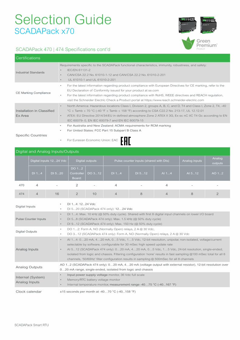
Digital and Analog Inputs/Outputs
Digital inputs 12...24 Vdc Digital outputs Pulse counter inputs (shared with DIs) Analog inputsAnalog
outputs
DI 1...4 DI 5...20
DO 1...2
Controller
Board:
DO 3...12 DI 1...4 DI 5...12 AI 1...4 AI 5...12 AO 1...2
470 4 - 2 - 4 - 4 - -
474 4 16 2 10 4 8 4 8 2
Digital Inputs• DI 1...4: 12...24 Vdc
• DI 5...20 (SCADAPack 474 only): 12…24 Vdc
Pulse Counter Inputs
• DI 1...4: Max. 10 kHz (@ 50% duty cycle). Shared with first 8 digital input channels on lower I/O board
• DI 5...8 (SCADAPack 474 only): Max. 1.5 kHz (@ 50% duty cycle)
• DI 9...12 (SCADAPack 474 only): Max. 150 Hz (@ 50% duty cycle)
Digital Outputs• DO 1...2: Form A, NO (Normally Open) relays, 2 A @ 30 Vdc,
• DO 3...12 (SCADAPack 474 only): Form A, NO (Normally Open) relays, 2 A @ 30 Vdc
Analog Inputs
• AI 1...4: 0…20 mA, 4…20 mA, 0…5 Vdc, 1…5 Vdc, 12-bit resolution, unipolar, non-isolated, voltage/current
selectable by software, configurable for 30 mSec high speed update rate
• AI 5...12 (SCADAPack 474 only): 0…20 mA, 4…20 mA, 0…5 Vdc, 1…5 Vdc, 24-bit resolution, single-ended,
isolated from logic and chassis. Filtering configuration ‘none’ results in fast sampling @100 mSec total for all 8
channels, ‘50/60Hz’ filter configuration results in sampling @ 500mSec for all 8 channels
Analog OutputsAO 1...2 (SCADAPack 474 only): 0…20 mA, 4…20 mA (voltage output with external resistor), 12-bit resolution over
0…20 mA range, single-ended, isolated from logic and chassis
Internal (System) Analog Inputs
• Input power supply voltage monitor, 36 Vdc full scale
• Memory/RTC battery voltage monitor
• Internal temperature monitor, measurement range -40…75 °C (-40...167 °F)
Clock calendar ±15 seconds per month at -40…70 °C (-40...158 °F)
SCADAPack Smart RTU
Selection GuideSCADAPack x70
SCADAPack 470 | 474 Specifications cont'd
Additional I/O
Supported Modules
• 5304, 5405, 5414, 5415, 5506, 5606, 5607, 6601, 6607
• When SCADAPack 47x controller is used with 5000-series I/O Expansion modules, order one Inter Module
Cable (IMC) adaptor cable (ref. TBUM297138), to adapt from 20 signal lines (used by SCADAPack x70 Smart
RTUs) to 16 signal lines (used by 5000-series IO modules)
• Maximum number of external expansion modules per unit: 15 *
I/O Expansion Limits *
• Refer to the SCADAPack x70 Documentation Set > Hardware Manuals for further details.
• Maximum intermodule cable length (not including the short cables that come with each module) is 1.82 m (75
in.)
* Additional power supply modules (model 5103) may be required for additional bus power, depending on how many expansion modules are
included on the bus. Refer to the SCADAPack x70 Documentation Set for further details.
Life is On | Schneider Electric 27

Selection GuideSCADAPack x70
SCADAPack 470 | 474 Model Code
Code Select: Hardware Platform
TBUP470 SCADAPack 470, 32-bit controller, Dual Core
TBUP474 SCADAPack 474, 32-bit controller, Dual Core comes with additional I/O
Code Select: Firmware Platform
U SCADAPack x70 Firmware (RemoteConnect Configuration & IEC 61131-3 programming software, included)
Code Select: SCADA Security
A Standard security features
C DNP3 Secure Authentication SAv2 (Security Administrator application required)
Code Select: Protocol Option
5 DNP3 Serial/IP client/outstation/peer-to-peer, Modbus RTU/TCP client/server, TCP/IP
Code Select: License Option
0 None
7DNP3 Data Concentrator Master License – allows collection of DNP3 events and data from multiple
outstations
Code Select: Analog Inputs
A P470: 4 Analog Inputs, selectable as 0…20 mA, 4…20 mA, 0…5 Vdc, 1…5 Vdc
BP474: adds 8 Analog Inputs, factory-shipped selectable as 0…20 mA, 4…20 mA, 0…5 Vdc, 1…5 Vdc, and
2 Analog Outputs, selectable as 0...20 or 4...20 mA
Code Select: Digital Inputs/Outputs
A P470: 4 Digital Inputs (12...24 Vdc), 2 Digital Outputs Form A, NO (Normally Open) relays
BP474: adds 16 Digital Inputs (12...24 Vdc) and 10 Digital Outputs Form A NO (Normally
Open) relays
Code Select: Analog Outputs
0 None
1574 and 575: 2 channel Analog Output option, shipped selectable as 0…20 mA or 4…20 mA, external
DC supply required
Code Future Option
0 None
Code Select: Realflo Flow Computer - Flow Run License Options
0 None
33 Runs - any combination of gas, liquid or water totaling 3 runs (gas runs include gas transmission
option)
66 Runs - any combination of gas, liquid or water totaling 6 runs (gas runs include gas transmission
option)
T10 Runs - any combination of gas, liquid or water totaling 10 runs (gas runs include gas transmission
option)
Code Select: Certifications
S
• FCC 47 CFR Part 15, Subpart B; ICES-003; CE and RCM markings, cULus Hazardous Location Class
I, Division 2, Groups A, B, C and D, T4; and Class I, Zone 2, IIC
• ATEX: EU Directive 2014/34/EU) in defined atmosphere Zone 2 ATEX II 3G, Ex ec nC IIC T4 Gc
according to EN IEC 60079- 0, EN IEC 60079-7 and EN IEC 60079-15
• For Eurasian Economic Union: EAC
SCADAPack Smart RTU
Selection GuideSCADAPack x70
SCADAPack 570 | 574 | 575 Specifications
Architecture
Processor SPEAr 1380 32-bit dual-core Cortex A9 microcontroller, 500 MHz
Memory• 128 MB NAND FLASH, 128 MB DDR3 RAM
• Non-Volatile RAM CMOS SRAM with lithium battery retains contents for 2 years with no power
Maximum DNP3 and
IEC 60870-5-104 eventsUp to 40,000 time-stamped DNP3 events (reduced if database exceeds 10,000 objects)
Database CapacityTypical maximum 15,000 objects, max. number of logic connected objects is 6000 (subset of 15,000
total objects)
DNP3 Data Concentrator
Client
(Optional) Manages up to 100* DNP3 peer (server) devices for collection of DNP3 data and events from
other DNP3 outstations
DNP3 Client Stations Up to 3
DNP3 Peer Devices Up to 90
Modbus Client Up to 80* simultaneous Modbus TCP client (outgoing client) connections
Modbus Server Up to 20* Modbus TCP server (incoming server) connections
File System Storage Internal: 70 MB usable; External: 32 GB (using optional memory stick)
USB host storage• Single-partition plug-in USB mass storage devices up to 32 GB
• File format: FAT32
Communications
Serial Ports: Serial1,
Serial2
RS-232 port, 8-pin modular RJ45 jack, +5 Vdc power control, hardware handshaking, maximum baud
rate 115,200 bps
• Rated to ±15 kV (IEC 61000-4-2, Air Discharge) static protection
Serial Ports: Serial3, Serial4
Configurable as:
• RS-232 or RS-485 two wire, half duplex, maximum baud rate 115,200 bps
• 8-pin modular RJ45 jack, rated to ±15 kV (IEC 61000-4-2, Air Discharge) static protection
Serial Protocols DNP3 level 4 server/client and peer-to-peer, Modbus RTU server/client
Ethernet Ports:
Eth1, Eth2, Eth38-pin modular RJ45 jack, 10/100 Mbps UTP (10/100 Base-T), transformer isolated
IP Protocols
• DNP3 level 4 in TCP or in UDP Client/Server and peer-to-peer,
• Modbus/TCP Server, Modbus/TCP Client
• IEC 60870-5-104 controlled station
• Telnet Server, FTP Server
• HART pass through over TCP when connected to SCADAPack 6602 modules
USB Device Port USB 2.0-compliant “B”-type receptacle, for local configuration
USB Host Port USB 2.0-compliant “A”-type receptacle, supports USB devices up to 32 GB
Life is On | Schneider Electric 29
Selection GuideSCADAPack x70SCADAPack 570 | 574 | 575 Specifications
General
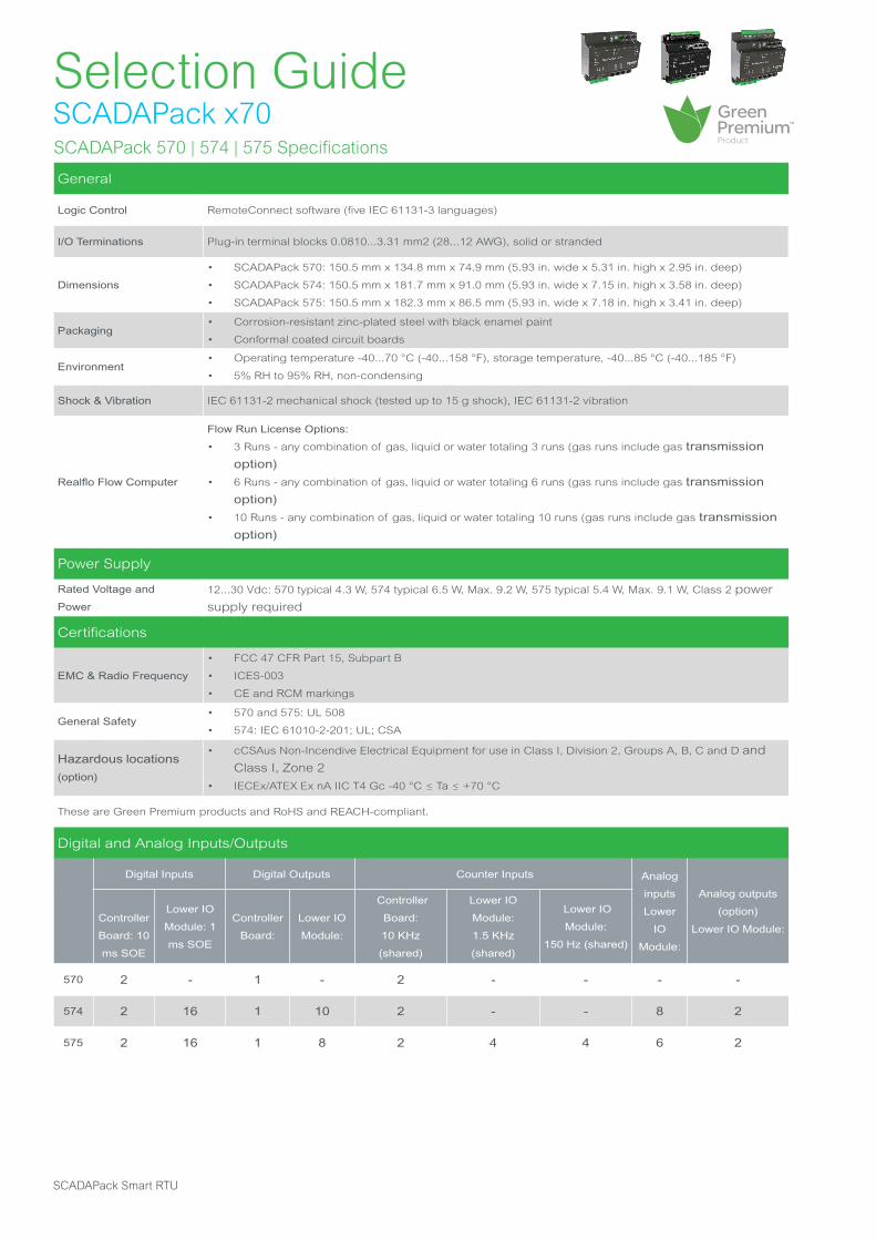
Logic Control RemoteConnect software (five IEC 61131-3 languages)
I/O Terminations Plug-in terminal blocks 0.0810...3.31 mm2 (28...12 AWG), solid or stranded
Dimensions
• SCADAPack 570: 150.5 mm x 134.8 mm x 74.9 mm (5.93 in. wide x 5.31 in. high x 2.95 in. deep)
• SCADAPack 574: 150.5 mm x 181.7 mm x 91.0 mm (5.93 in. wide x 7.15 in. high x 3.58 in. deep)
• SCADAPack 575: 150.5 mm x 182.3 mm x 86.5 mm (5.93 in. wide x 7.18 in. high x 3.41 in. deep)
Packaging• Corrosion-resistant zinc-plated steel with black enamel paint
• Conformal coated circuit boards
Environment• Operating temperature -40...70 °C (-40...158 °F), storage temperature, -40...85 °C (-40...185 °F)
• 5% RH to 95% RH, non-condensing
Shock & Vibration IEC 61131-2 mechanical shock (tested up to 15 g shock), IEC 61131-2 vibration
Realflo Flow Computer
Flow Run License Options:
• 3 Runs - any combination of gas, liquid or water totaling 3 runs (gas runs include gas transmission option)
• 6 Runs - any combination of gas, liquid or water totaling 6 runs (gas runs include gas transmission option)
• 10 Runs - any combination of gas, liquid or water totaling 10 runs (gas runs include gas transmission option)
Power Supply
Rated Voltage and
Power
12...30 Vdc: 570 typical 4.3 W, 574 typical 6.5 W, Max. 9.2 W, 575 typical 5.4 W, Max. 9.1 W, Class 2 power
supply required
Certifications
EMC & Radio Frequency
• FCC 47 CFR Part 15, Subpart B
• ICES-003
• CE and RCM markings
General Safety• 570 and 575: UL 508
• 574: IEC 61010-2-201; UL; CSA
Hazardous locations
(option)
• cCSAus Non-Incendive Electrical Equipment for use in Class I, Division 2, Groups A, B, C and D and
Class I, Zone 2
• IECEx/ATEX Ex nA IIC T4 Gc -40 °C ≤ Ta ≤ +70 °C
These are Green Premium products and RoHS and REACH-compliant.
Digital and Analog Inputs/Outputs
Digital Inputs Digital Outputs Counter Inputs Analog
inputs
Lower
IO
Module:
Analog outputs
(option)
Lower IO Module:
Controller
Board: 10
ms SOE
Lower IO
Module: 1
ms SOE
Controller
Board:
Lower IO
Module:
Controller
Board:
10 KHz
(shared)
Lower IO
Module:
1.5 KHz
(shared)
Lower IO
Module:
150 Hz (shared)
570 2 - 1 - 2 - - - -
574 2 16 1 10 2 - - 8 2
575 2 16 1 8 2 4 4 6 2
SCADAPack Smart RTU
SCADAPack 570 | 574 | 575 Specifications cont'd
Digital and Analog Inputs/Outputs cont'd
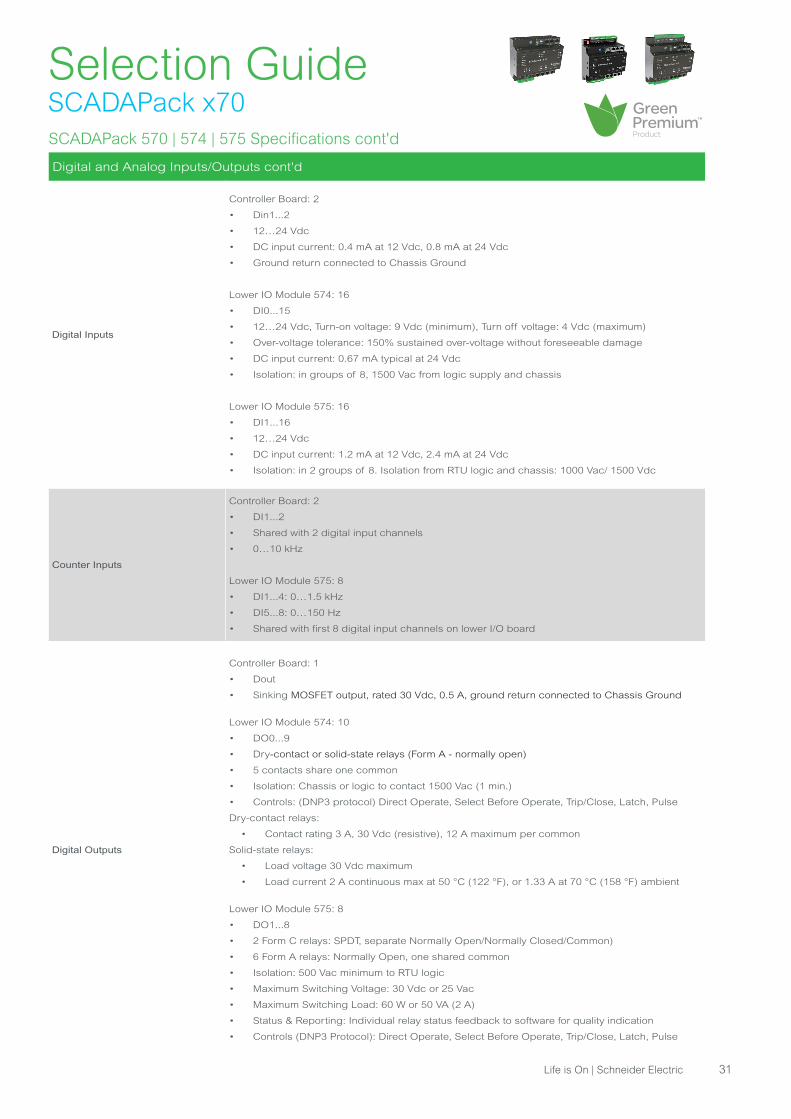
Digital Inputs
Controller Board: 2
• Din1...2
• 12…24 Vdc
• DC input current: 0.4 mA at 12 Vdc, 0.8 mA at 24 Vdc
• Ground return connected to Chassis Ground
Lower IO Module 574: 16
• DI0...15
• 12…24 Vdc, Turn-on voltage: 9 Vdc (minimum), Turn off voltage: 4 Vdc (maximum)
• Over-voltage tolerance: 150% sustained over-voltage without foreseeable damage
• DC input current: 0.67 mA typical at 24 Vdc
• Isolation: in groups of 8, 1500 Vac from logic supply and chassis
Lower IO Module 575: 16
• DI1...16
• 12…24 Vdc
• DC input current: 1.2 mA at 12 Vdc, 2.4 mA at 24 Vdc
• Isolation: in 2 groups of 8. Isolation from RTU logic and chassis: 1000 Vac/ 1500 Vdc
Counter Inputs
Controller Board: 2
• DI1...2
• Shared with 2 digital input channels
• 0…10 kHz
Lower IO Module 575: 8
• DI1...4: 0…1.5 kHz
• DI5...8: 0…150 Hz
• Shared with first 8 digital input channels on lower I/O board
Digital Outputs
Controller Board: 1
• Dout
• Sinking MOSFET output, rated 30 Vdc, 0.5 A, ground return connected to Chassis Ground
Lower IO Module 574: 10
• DO0...9
• Dry-contact or solid-state relays (Form A - normally open)
• 5 contacts share one common
• Isolation: Chassis or logic to contact 1500 Vac (1 min.)
• Controls: (DNP3 protocol) Direct Operate, Select Before Operate, Trip/Close, Latch, Pulse
Dry-contact relays:
• Contact rating 3 A, 30 Vdc (resistive), 12 A maximum per common
Solid-state relays:
• Load voltage 30 Vdc maximum
• Load current 2 A continuous max at 50 °C (122 °F), or 1.33 A at 70 °C (158 °F) ambient
Lower IO Module 575: 8
• DO1...8
• 2 Form C relays: SPDT, separate Normally Open/Normally Closed/Common)
• 6 Form A relays: Normally Open, one shared common
• Isolation: 500 Vac minimum to RTU logic
• Maximum Switching Voltage: 30 Vdc or 25 Vac
• Maximum Switching Load: 60 W or 50 VA (2 A)
• Status & Reporting: Individual relay status feedback to software for quality indication
• Controls (DNP3 Protocol): Direct Operate, Select Before Operate, Trip/Close, Latch, Pulse
Life is On | Schneider Electric 31
Selection GuideSCADAPack x70
Additional I/O
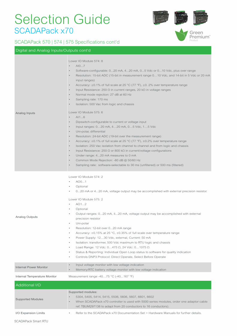
Supported Modules
Supported modules:
• 5304, 5405, 5414, 5415, 5506, 5606, 5607, 6601, 6602
• When SCADAPack x70 controller is used with 5000 series modules, order one adaptor cable
ref. TBUM297138 to adapt from 20 conductors to 16 conductors).
I/O Expansion Limits • Refer to the SCADAPack x70 Documentation Set > Hardware Manuals for further details.
SCADAPack Smart RTU
SCADAPack 570 | 574 | 575 Specifications cont'd
Digital and Analog Inputs/Outputs cont'd
Analog Inputs
Lower IO Module 574: 8
• AI0...7
• Software-configurable: 0...20 mA, 4...20 mA, 0...5 Vdc or 0...10 Vdc, plus over range
• Resolution: 15-bit ADC (15-bit in measurement range 0…10 Vdc, and 14-bit in 5 Vdc or 20 mA
input ranges)
• Accuracy: ±0.1% of full scale at 25 °C (77 °F), ±0. 2% over temperature range
• Input Resistance: 250 Ω in current ranges, 20 kΩ in voltage ranges
• Normal mode rejection: 27 dB at 60 Hz
• Sampling rate: 170 ms
• Isolation: 500 Vac from logic and chassis
Lower IO Module 575: 6
• AI1...6
• Dipswitch-configurable to current or voltage input
• Input ranges: 0…20 mA, 4…20 mA, 0…5 Vdc, 1…5 Vdc
• Uni-polar, differential
• Resolution: 24-bit ADC (19-bit over the measurement range)
• Accuracy: ±0.1% of full scale at 25 °C (77 °F), ±0.2% over temperature range
• Isolation: 250 Vac isolation from channel to channel and from logic and chassis
• Input Resistance: 250 Ω or 800 kΩ in current/voltage configurations
• Under range: 4...20 mA measures to 0 mA
• Common Mode Rejection: -80 dB @ 50/60 Hz
• Sampling rate: software-selectable to 30 ms (unfiltered) or 500 ms (filtered)
Analog Outputs
Lower IO Module 574: 2
• AO0...1
• Optional
• 0...20 mA or 4...20 mA, voltage output may be accomplished with external precision resistor.
Lower IO Module 575: 2
• AO1...2
• Optional
• Output ranges: 0...20 mA, 4...20 mA, voltage output may be accomplished with external
precision resistor
• Uni-polar
• Resolution: 12-bit over 0...20 mA range
• Accuracy: ±0.15% at 25 °C, ±0.35% of full scale over temperature range
• Power Supply: 12…30 Vdc, external, Current: 50 mA
• Isolation: transformer, 500 Vdc maximum to RTU logic and chassis
• Load Range: 12 Vdc: 0…475 Ω, 24 Vdc: 0…1075 Ω
• Status & Reporting: Individual Open Loop status to software for quality indication
• Controls DNP3 Protocol: Direct Operate, Select Before Operate
Internal Power Monitor• Input voltage monitor with low voltage indication
• Memory/RTC battery voltage monitor with low voltage indication
Internal Temperature Monitor Measurement range -40…75 °C (-40...167 °F)
Selection GuideSCADAPack x70
SCADAPack 570 | 574 | 575 Model Code
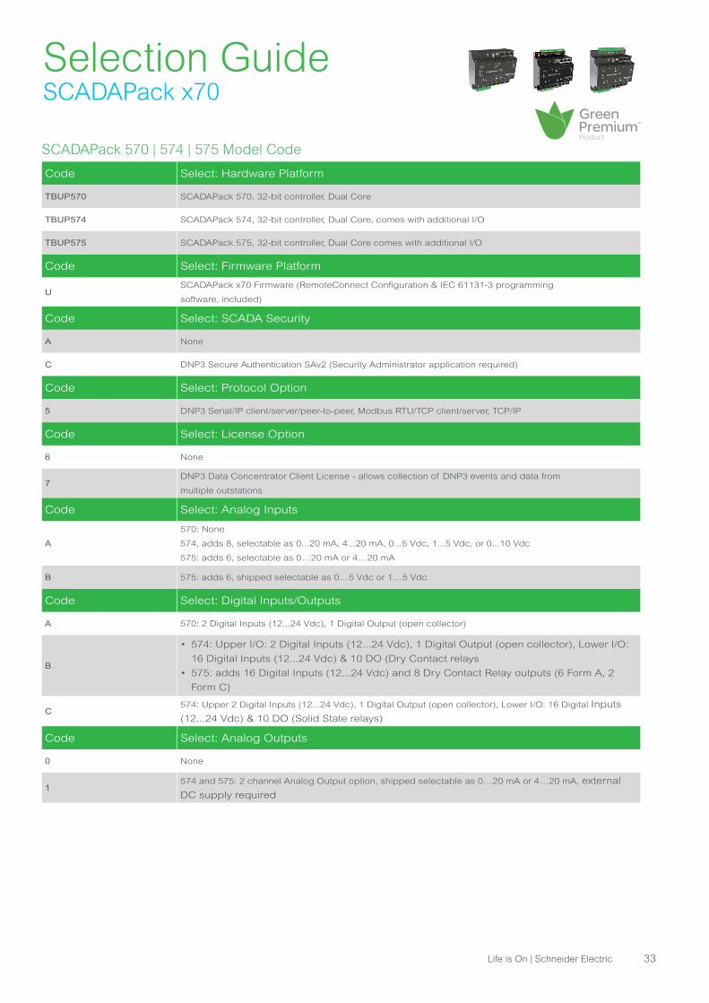
Code Select: Hardware Platform
TBUP570 SCADAPack 570, 32-bit controller, Dual Core
TBUP574 SCADAPack 574, 32-bit controller, Dual Core, comes with additional I/O
TBUP575 SCADAPack 575, 32-bit controller, Dual Core comes with additional I/O
Code Select: Firmware Platform
USCADAPack x70 Firmware (RemoteConnect Configuration & IEC 61131-3 programming
software, included)
Code Select: SCADA Security
A None
C DNP3 Secure Authentication SAv2 (Security Administrator application required)
Code Select: Protocol Option
5 DNP3 Serial/IP client/server/peer-to-peer, Modbus RTU/TCP client/server, TCP/IP
Code Select: License Option
6 None
7DNP3 Data Concentrator Client License - allows collection of DNP3 events and data from
multiple outstations
Code Select: Analog Inputs
A
570: None
574, adds 8, selectable as 0...20 mA, 4...20 mA, 0...5 Vdc, 1...5 Vdc, or 0...10 Vdc
575: adds 6, selectable as 0…20 mA or 4…20 mA
B 575: adds 6, shipped selectable as 0…5 Vdc or 1…5 Vdc
Code Select: Digital Inputs/Outputs
A 570: 2 Digital Inputs (12...24 Vdc), 1 Digital Output (open collector)
B
• 574: Upper I/O: 2 Digital Inputs (12...24 Vdc), 1 Digital Output (open collector), Lower I/O:
16 Digital Inputs (12...24 Vdc) & 10 DO (Dry Contact relays
• 575: adds 16 Digital Inputs (12...24 Vdc) and 8 Dry Contact Relay outputs (6 Form A, 2
Form C)
C574: Upper 2 Digital Inputs (12...24 Vdc), 1 Digital Output (open collector), Lower I/O: 16 Digital Inputs
(12...24 Vdc) & 10 DO (Solid State relays)
Code Select: Analog Outputs
0 None
1574 and 575: 2 channel Analog Output option, shipped selectable as 0…20 mA or 4…20 mA, external
DC supply required
Life is On | Schneider Electric 33
Selection GuideSCADAPack x70
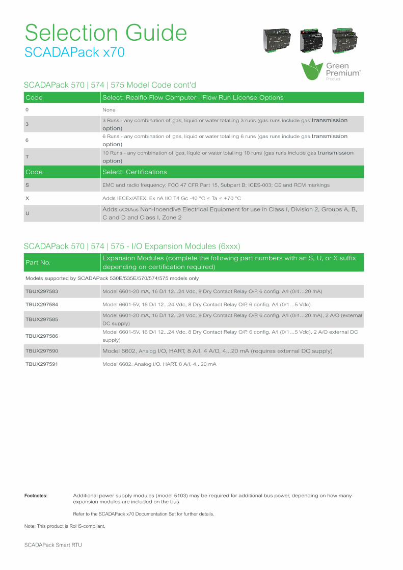
SCADAPack 570 | 574 | 575 - I/O Expansion Modules (6xxx)
Part No.Expansion Modules (complete the following part numbers with an S, U, or X suffix
depending on certification required)
Models supported by SCADAPack 530E/535E/570/574/575 models only
TBUX297583 Model 6601-20 mA, 16 D/I 12...24 Vdc, 8 Dry Contact Relay O/P, 6 config. A/I (0/4…20 mA)
TBUX297584 Model 6601-5V, 16 D/I 12...24 Vdc, 8 Dry Contact Relay O/P, 6 config. A/I (0/1…5 Vdc)
TBUX297585Model 6601-20 mA, 16 D/I 12...24 Vdc, 8 Dry Contact Relay O/P, 6 config. A/I (0/4…20 mA), 2 A/O (external
DC supply)
TBUX297586Model 6601-5V, 16 D/I 12...24 Vdc, 8 Dry Contact Relay O/P, 6 config. A/I (0/1…5 Vdc), 2 A/O external DC
supply)
TBUX297590 Model 6602, Analog I/O, HART, 8 A/I, 4 A/O, 4...20 mA (requires external DC supply)
TBUX297591 Model 6602, Analog I/O, HART, 8 A/I, 4...20 mA
Footnotes: Additional power supply modules (model 5103) may be required for additional bus power, depending on how many expansion modules are included on the bus.
Refer to the SCADAPack x70 Documentation Set for further details.
Note: This product is RoHS-compliant.
SCADAPack Smart RTU
SCADAPack 570 | 574 | 575 Model Code cont'd
Code Select: Realflo Flow Computer - Flow Run License Options
0 None
33 Runs - any combination of gas, liquid or water totalling 3 runs (gas runs include gas transmission option)
66 Runs - any combination of gas, liquid or water totalling 6 runs (gas runs include gas transmission option)
T10 Runs - any combination of gas, liquid or water totalling 10 runs (gas runs include gas transmission option)
Code Select: Certifications
S EMC and radio frequency; FCC 47 CFR Part 15, Subpart B; ICES-003; CE and RCM markings
X Adds IECEx/ATEX: Ex nA IIC T4 Gc -40 °C ≤ Ta ≤ +70 °C
UAdds cCSAus Non-Incendive Electrical Equipment for use in Class I, Division 2, Groups A, B,
C and D and Class I, Zone 2
Selection GuideSCADAPack x70
Selection GuideSCADAPack E
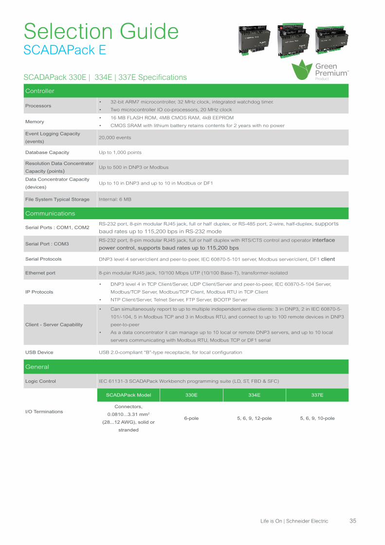
SCADAPack 330E | 334E | 337E Specifications
Controller
Processors• 32-bit ARM7 microcontroller, 32 MHz clock, integrated watchdog timer.
• Two microcontroller IO co-processors, 20 MHz clock
Memory• 16 MB FLASH ROM, 4MB CMOS RAM, 4kB EEPROM
• CMOS SRAM with lithium battery retains contents for 2 years with no power
Event Logging Capacity
(events)20,000 events
Database Capacity Up to 1,000 points
Resolution Data Concentrator
Capacity (points)Up to 500 in DNP3 or Modbus
Data Concentrator Capacity
(devices) Up to 10 in DNP3 and up to 10 in Modbus or DF1
File System Typical Storage Internal: 6 MB
Communications
Serial Ports : COM1, COM2RS-232 port, 8-pin modular RJ45 jack, full or half duplex, or RS-485 port, 2-wire, half-duplex, supports
baud rates up to 115,200 bps in RS-232 mode
Serial Port : COM3RS-232 port, 8-pin modular RJ45 jack, full or half duplex with RTS/CTS control and operator interface
power control, supports baud rates up to 115,200 bps
Serial Protocols DNP3 level 4 server/client and peer-to-peer, IEC 60870-5-101 server, Modbus server/client, DF1 client
Ethernet port 8-pin modular RJ45 jack, 10/100 Mbps UTP (10/100 Base-T), transformer-isolated
IP Protocols
• DNP3 level 4 in TCP Client/Server, UDP Client/Server and peer-to-peer, IEC 60870-5-104 Server,
Modbus/TCP Server, Modbus/TCP Client, Modbus RTU in TCP Client
• NTP Client/Server, Telnet Server, FTP Server, BOOTP Server
Client - Server Capability
• Can simultaneously report to up to multiple independent active clients: 3 in DNP3, 2 in IEC 60870-5-
101/-104, 5 in Modbus TCP and 3 in Modbus RTU, and connect to up to 100 remote devices in DNP3
peer-to-peer
• As a data concentrator it can manage up to 10 local or remote DNP3 servers, and up to 10 local
servers communicating with Modbus RTU, Modbus TCP or DF1 serial
USB Device USB 2.0-compliant “B”-type receptacle, for local configuration
General
Logic Control IEC 61131-3 SCADAPack Workbench programming suite (LD, ST, FBD & SFC)
I/O Terminations
SCADAPack Model 330E 334E 337E
Connectors,
0.0810...3.31 mm2
(28...12 AWG), solid or
stranded
6-pole 5, 6, 9, 12-pole 5, 6, 9, 10-pole
Life is On | Schneider Electric 35
Selection GuideSCADAPack E
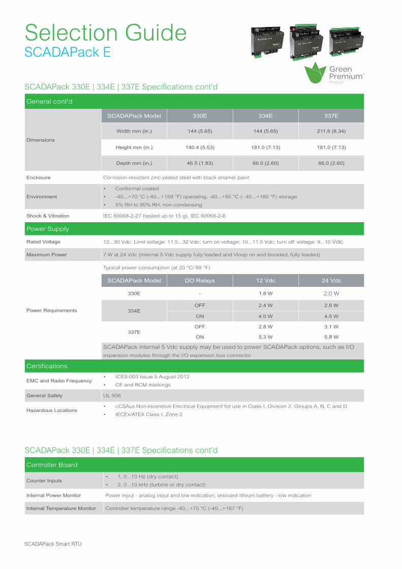
SCADAPack 330E | 334E | 337E Specifications cont'd
General cont'd
Dimensions
SCADAPack Model 330E 334E 337E
Width mm (in.) 144 (5.65) 144 (5.65) 211.8 (8.34)
Height mm (in.) 140.4 (5.53) 181.0 (7.13) 181.0 (7.13)
Depth mm (in.) 46.5 (1.83) 66.0 (2.60) 66.0 (2.60)
Enclosure Corrosion-resistant zinc-plated steel with black enamel paint
Environment
• Conformal coated
• -40...+70 °C (-40...+158 °F) operating, -40...+85 °C (- 40...+185 °F) storage
• 5% RH to 95% RH, non-condensing
Shock & Vibration IEC 60068-2-27 (tested up to 15 g), IEC 60068-2-6
Power Supply
Rated Voltage 12...30 Vdc. Limit voltage: 11.5...32 Vdc; turn on voltage: 10...11.5 Vdc; turn off voltage: 9...10 Vdc
Maximum Power 7 W at 24 Vdc (internal 5 Vdc supply fully loaded and Vloop on and boosted, fully loaded)
Power Requirements
Typical power consumption (at 20 °C/ 68 °F)
SCADAPack Model DO Relays 12 Vdc 24 Vdc
330E - 1.8 W 2.0 W
334EOFF 2.4 W 2.8 W
ON 4.0 W 4.5 W
337EOFF 2.8 W 3.1 W
ON 5.3 W 5.8 W
SCADAPack internal 5 Vdc supply may be used to power SCADAPack options, such as I/O
expansion modules through the I/O expansion bus connector
Certifications
EMC and Radio Frequency• ICES-003 Issue 5 August 2012
• CE and RCM markings
General Safety UL 508
Hazardous Locations• cCSAus Non-incendive Electrical Equipment for use in Class I, Division 2, Groups A, B, C and D
• IECEx/ATEX Class I, Zone 2
SCADAPack Smart RTU
SCADAPack 330E | 334E | 337E Specifications cont'd
Controller Board
Counter Inputs• 1, 0...10 Hz (dry contact)
• 2, 0...10 kHz (turbine or dry contact)
Internal Power Monitor Power input - analog input and low indication, onboard lithium battery - low indication
Internal Temperature Monitor Controller temperature range -40...+75 °C (-40...+167 °F)
Selection GuideSCADAPack E
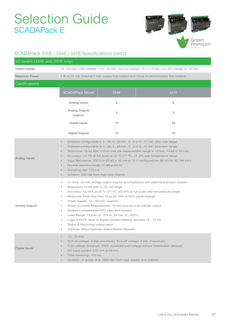
SCADAPack 330E | 334E | 337E Specifications cont'd
I/O board (334E and 337E only)
Rated Voltage 12...30 Vdc. Limit voltage: 11.5...32 Vdc; turn on voltage: 10...11.5 Vdc; turn off voltage: 9...10 Vdc
Maximum Power 7 W at 24 Vdc (internal 5 Vdc supply fully loaded and Vloop on and boosted, fully loaded)
Certifications
SCADAPack Model 334E 337E
Analog Inputs 8 8
Analog Outputs
(option)2 2
Digital Inputs 16 32
Digital Outputs 10 16
Analog Inputs
• Software-configurable to 0...20, 4...20 mA , 0...5 or 0...10 Vdc, plus over range
• Software-configurable to 0...20, 4...20 mA , 0...5 or 0...10 Vdc, plus over range
• Resolution: 15-bit ADC (15-bit over the measurement range in 10 Vdc, 14-bit in 20 mA)
• Accuracy: ±0.1% of full scale at 25 °C (77 °F), ±0. 2% over temperature range
• Input Resistance: 250 Ω or 20 kΩ in 20 mA or 10 V configurations (60 kΩ for 32.768 Vdc)
• Normal rejection mode: 27 dB at 60 Hz
• Sampling rate: 170 ms
• Isolation: 500 Vac from logic and chassis
Analog Outputs
• 0...20/4...20 mA, voltage output may be accomplished with external precision resistor
• Resolution: 12-bit over 0...20 mA range
• Accuracy: ±0.15% at 25 °C (77 °F), ±0.35% of full scale over temperature range
• Response Time: less than 10 μs for 10% to 90% signal change
• Power Supply: 12…30 Vdc, external
• Power (Current) Requirements: 10 mA plus up to 20 mA per output
• Isolation: isolated from RTU logic and chassis
• Load Range: 12 Vdc: 0…375 Ω, 24 Vdc: 0…925 Ω
• Logic End-Of- Scan to Signal Update Latency: typically 18... 27 ms
• Status & Reporting: output value
• Controls: Direct Operate, Select Before Operate
Digital Inputs
• 12…24 Vdc
• Turn on voltage: 9 Vdc (minimum), Turn off voltage: 4 Vdc (maximum)
• Over-voltage tolerance: 150% sustained over-voltage without foreseeable damage
• DC input current: 0.67 mA at 24 Vdc
• Time stamping : 170 ms
• Isolation : in group of 8, 1500 Vac from logic supply and chassis
Life is On | Schneider Electric 37

Selection GuideSCADAPack E
SCADAPack 330E | 334E | 337E Specifications cont'd
Certifications cont'd
Digital Outputs
• Relays (Form A)
• 4 contacts share one common
• Isolation : isolated in groups of 4 (P337E) or 5 (P334E). Isolated from RTU logic, RTU chassis and
other groups to 1500 Vac
• Maximum Switching Voltage: 30 Vdc or 250 Vac (resistive)
• Maximum Switching Load: 150 W or 1250 VA (5 A)
• Controls: Direct Operate, Select Before Operate, Trip/Close, Latch, Pulse
Additional I/O
I/O Expansion
5606, 5607 and 5304, 5404, 5411, 5414, 5415, 5505 and 5506
Maximum number of modules per unit:
• SCADAPack 330E: 8 (*)
• SCADAPack 334E and 337E: 7 (*)
(*): to reach this limit, additional power supply modules are required
SCADAPack 330E | 334E | 337E Model Code
Code Select: Controller
TBUP330 SCADAPack 330E, Controller 32-bit, 3 High Speed Counter Inputs
TBUP334 SCADAPack 334E, Controller 32-bit, comes with the above plus additional I/Os
TBUP337 SCADAPack 337E, Controller 32-bit, comes with the above plus additional I/Os
Code Select: Firmware Platform
ESCADAPack E Firmware (Configuration Software included), executes two IEC 61131 kernels, Workbench
required
Code Select: SCADA Security
A None
B AGA-12 Encryption for DNP3 (Security Administrator application required)
C DNP3 Secure Authentication SAv2 (Security Administrator application required)
D DNP3 Secure Authentication with AGA-12 (Security Administrator application required)
Code Select: Protocol Option
5DNP3 Serial/IP client/server/peer-to-peer, IEC 60870-5-101/104 Server, Modbus RTU/TCP client/server,
TCP/IP
Code Select: License Option *
5 IEC61131 (executes two kernels, SCADAPack Workbench required), and DF1 client
Footnotes: * Includes DNP3 Data Concentrator License (limit of 500 points from 10 IEDs) Multiple DNP3 Client License (up to 3 Clients)
SCADAPack Smart RTU
Selection GuideSCADAPack E
SCADAPack 330E | 334E | 337E Model Code cont'd
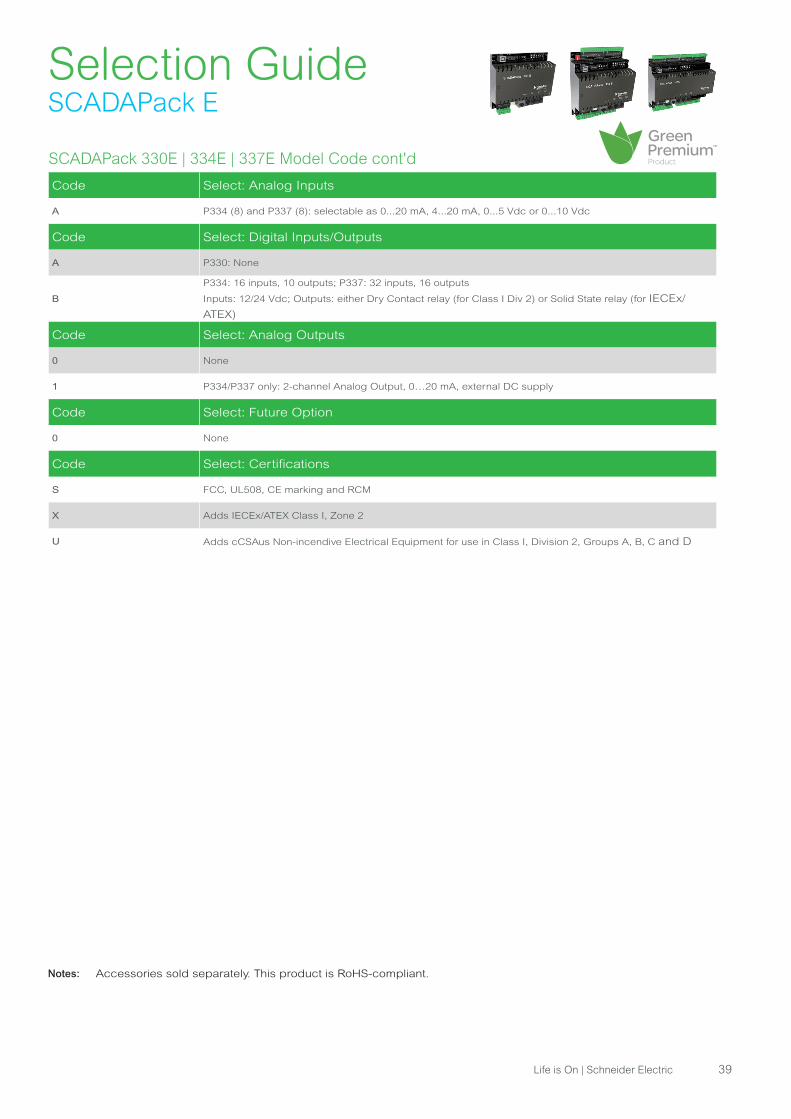
Code Select: Analog Inputs
A P334 (8) and P337 (8): selectable as 0...20 mA, 4...20 mA, 0...5 Vdc or 0...10 Vdc
Code Select: Digital Inputs/Outputs
A P330: None
B
P334: 16 inputs, 10 outputs; P337: 32 inputs, 16 outputs
Inputs: 12/24 Vdc; Outputs: either Dry Contact relay (for Class I Div 2) or Solid State relay (for IECEx/
ATEX)
Code Select: Analog Outputs
0 None
1 P334/P337 only: 2-channel Analog Output, 0…20 mA, external DC supply
Code Select: Future Option
0 None
Code Select: Certifications
S FCC, UL508, CE marking and RCM
X Adds IECEx/ATEX Class I, Zone 2
U Adds cCSAus Non-incendive Electrical Equipment for use in Class I, Division 2, Groups A, B, C and D
Notes: Accessories sold separately. This product is RoHS-compliant.
Life is On | Schneider Electric 39
Selection GuideSCADAPack E
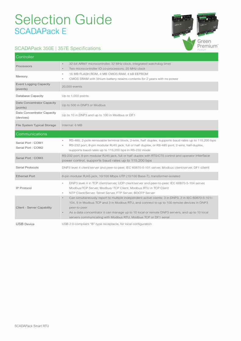
SCADAPack 350E | 357E Specifications
Controller
Processors• 32-bit ARM7 microcontroller, 32 MHz clock, integrated watchdog timer.
• Two microcontroller IO co-processors, 20 MHz clock
Memory• 16 MB FLASH ROM, 4 MB CMOS RAM, 4 kB EEPROM
• CMOS SRAM with lithium battery retains contents for 2 years with no power
Event Logging Capacity
(events)20,000 events
Database Capacity Up to 1,000 points
Data Concentrator Capacity
(points)Up to 500 in DNP3 or Modbus
Data Concentrator Capacity
(devices) Up to 10 in DNP3 and up to 100 in Modbus or DF1
File System Typical Storage Internal: 6 MB
Communications
Serial Port : COM1
Serial Port : COM2
• RS-485, 2-pole removable terminal block, 2-wire, half duplex, supports baud rates up to 115,200 bps
• RS-232 port, 8-pin modular RJ45 jack, full or half duplex, or RS-485 port, 2-wire, half-duplex,
supports baud rates up to 115,200 bps in RS-232 mode
Serial Port : COM3RS-232 port, 8-pin modular RJ45 jack, full or half duplex with RTS/CTS control and operator interface
power control, supports baud rates up to 115,200 bps
Serial Protocols DNP3 level 4 client/server and peer-to-peer, IEC 60870-5-101 server, Modbus client/server, DF1 client
Ethernet Port 8-pin modular RJ45 jack, 10/100 Mbps UTP (10/100 Base-T), transformer-isolated
IP Protocol
• DNP3 level 4 in TCP client/server, UDP client/server and peer-to-peer, IEC 60870-5-104 server,
Modbus/TCP Server, Modbus/ TCP Client, Modbus RTU in TCP Client
• NTP Client/Server, Telnet Server, FTP Server, BOOTP Server
Client - Server Capability
• Can simultaneously report to multiple independent active clients: 3 in DNP3, 2 in IEC 60870-5-101/-
104, 5 in Modbus TCP and 3 in Modbus RTU, and connect to up to 100 remote devices in DNP3
peer-to-peer
• As a data concentrator it can manage up to 10 local or remote DNP3 servers, and up to 10 local
servers communicating with Modbus RTU, Modbus TCP or DF1 serial
USB Device USB 2.0-compliant “B”-type receptacle, for local configuration
SCADAPack Smart RTU
Selection GuideSCADAPack E
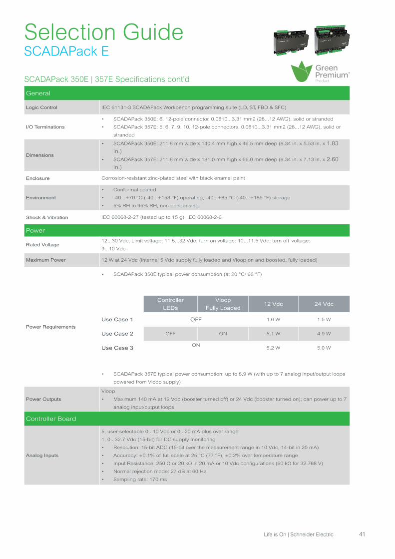
SCADAPack 350E | 357E Specifications cont'd
General
Logic Control IEC 61131-3 SCADAPack Workbench programming suite (LD, ST, FBD & SFC)
I/O Terminations
• SCADAPack 350E: 6, 12-pole connector, 0.0810...3.31 mm2 (28...12 AWG), solid or stranded
• SCADAPack 357E: 5, 6, 7, 9, 10, 12-pole connectors, 0.0810...3.31 mm2 (28...12 AWG), solid or
stranded
Dimensions
• SCADAPack 350E: 211.8 mm wide x 140.4 mm high x 46.5 mm deep (8.34 in. x 5.53 in. x 1.83
in.)
• SCADAPack 357E: 211.8 mm wide x 181.0 mm high x 66.0 mm deep (8.34 in. x 7.13 in. x 2.60
in.)
Enclosure Corrosion-resistant zinc-plated steel with black enamel paint
Environment
• Conformal coated
• -40...+70 °C (-40...+158 °F) operating, -40...+85 °C (-40...+185 °F) storage
• 5% RH to 95% RH, non-condensing
Shock & Vibration IEC 60068-2-27 (tested up to 15 g), IEC 60068-2-6
Power
Rated Voltage12...30 Vdc. Limit voltage: 11.5...32 Vdc; turn on voltage: 10...11.5 Vdc; turn off voltage:
9...10 Vdc
Maximum Power 12 W at 24 Vdc (internal 5 Vdc supply fully loaded and Vloop on and boosted, fully loaded)
Power Requirements
• SCADAPack 350E typical power consumption (at 20 °C/ 68 °F)
Controller
LEDs
Vloop
Fully Loaded12 Vdc 24 Vdc
Use Case 1 OFF 1.6 W 1.5 W
Use Case 2 OFF ON 5.1 W 4.9 W
Use Case 3ON
5.2 W 5.0 W
• SCADAPack 357E typical power consumption: up to 8.9 W (with up to 7 analog input/output loops
powered from Vloop supply)
Power Outputs
Vloop
• Maximum 140 mA at 12 Vdc (booster turned off) or 24 Vdc (booster turned on); can power up to 7
analog input/output loops
Controller Board
Analog Inputs
5, user-selectable 0...10 Vdc or 0...20 mA plus over range
1, 0...32.7 Vdc (15-bit) for DC supply monitoring
• Resolution: 15-bit ADC (15-bit over the measurement range in 10 Vdc, 14-bit in 20 mA)
• Accuracy: ±0.1% of full scale at 25 °C (77 °F), ±0.2% over temperature range
• Input Resistance: 250 Ω or 20 kΩ in 20 mA or 10 Vdc configurations (60 kΩ for 32.768 V)
• Normal rejection mode: 27 dB at 60 Hz
• Sampling rate: 170 ms
Life is On | Schneider Electric 41
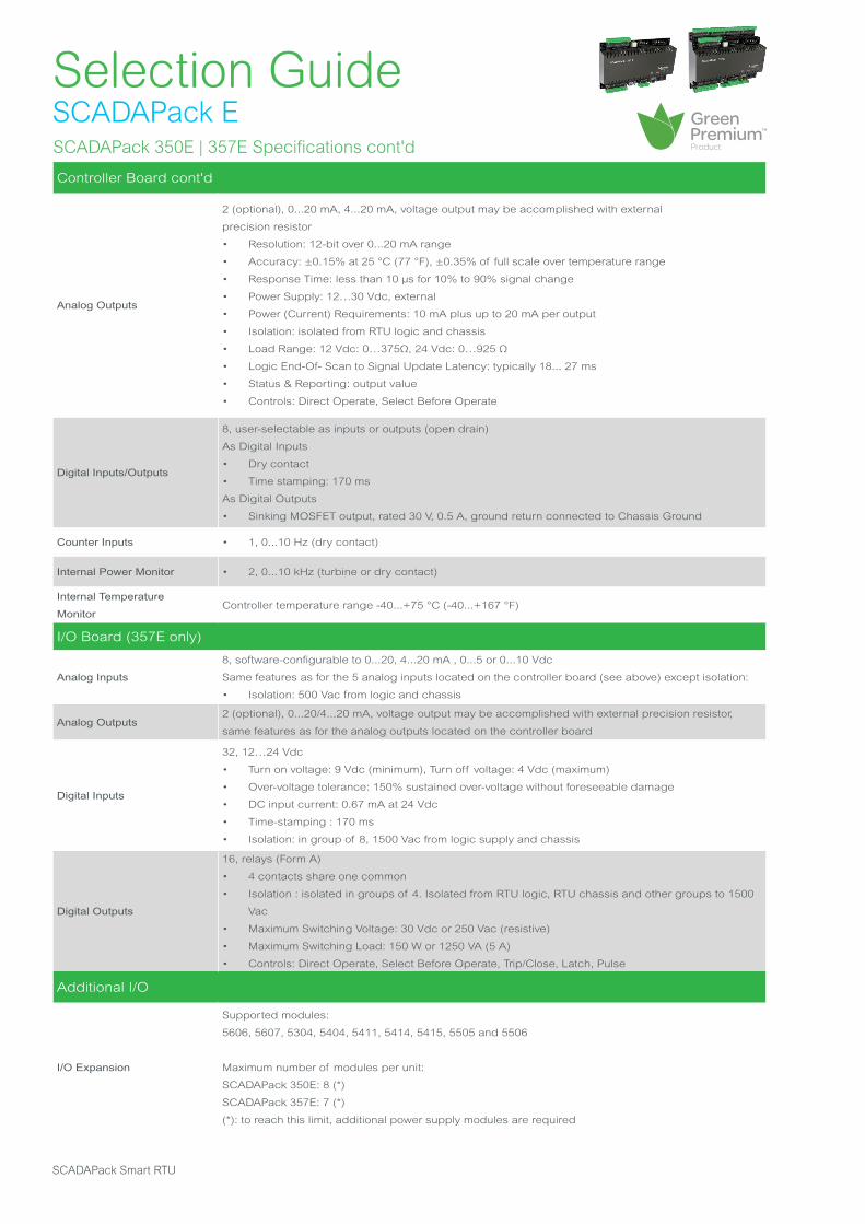
Selection GuideSCADAPack ESCADAPack 350E | 357E Specifications cont'd
Controller Board cont'd
Analog Outputs
2 (optional), 0...20 mA, 4...20 mA, voltage output may be accomplished with external
precision resistor
• Resolution: 12-bit over 0...20 mA range
• Accuracy: ±0.15% at 25 °C (77 °F), ±0.35% of full scale over temperature range
• Response Time: less than 10 μs for 10% to 90% signal change
• Power Supply: 12…30 Vdc, external
• Power (Current) Requirements: 10 mA plus up to 20 mA per output
• Isolation: isolated from RTU logic and chassis
• Load Range: 12 Vdc: 0…375Ω, 24 Vdc: 0…925 Ω
• Logic End-Of- Scan to Signal Update Latency: typically 18... 27 ms
• Status & Reporting: output value
• Controls: Direct Operate, Select Before Operate
Digital Inputs/Outputs
8, user-selectable as inputs or outputs (open drain)
As Digital Inputs
• Dry contact
• Time stamping: 170 ms
As Digital Outputs
• Sinking MOSFET output, rated 30 V, 0.5 A, ground return connected to Chassis Ground
Counter Inputs • 1, 0...10 Hz (dry contact)
Internal Power Monitor • 2, 0...10 kHz (turbine or dry contact)
Internal Temperature
MonitorController temperature range -40...+75 °C (-40...+167 °F)
I/O Board (357E only)
Analog Inputs
8, software-configurable to 0...20, 4...20 mA , 0...5 or 0...10 Vdc
Same features as for the 5 analog inputs located on the controller board (see above) except isolation:
• Isolation: 500 Vac from logic and chassis
Analog Outputs2 (optional), 0...20/4...20 mA, voltage output may be accomplished with external precision resistor,
same features as for the analog outputs located on the controller board
Digital Inputs
32, 12…24 Vdc
• Turn on voltage: 9 Vdc (minimum), Turn off voltage: 4 Vdc (maximum)
• Over-voltage tolerance: 150% sustained over-voltage without foreseeable damage
• DC input current: 0.67 mA at 24 Vdc
• Time-stamping : 170 ms
• Isolation: in group of 8, 1500 Vac from logic supply and chassis
Digital Outputs
16, relays (Form A)
• 4 contacts share one common
• Isolation : isolated in groups of 4. Isolated from RTU logic, RTU chassis and other groups to 1500
Vac
• Maximum Switching Voltage: 30 Vdc or 250 Vac (resistive)
• Maximum Switching Load: 150 W or 1250 VA (5 A)
• Controls: Direct Operate, Select Before Operate, Trip/Close, Latch, Pulse
Additional I/O
I/O Expansion
Supported modules:
5606, 5607, 5304, 5404, 5411, 5414, 5415, 5505 and 5506
Maximum number of modules per unit:
SCADAPack 350E: 8 (*)
SCADAPack 357E: 7 (*)
(*): to reach this limit, additional power supply modules are required
SCADAPack Smart RTU
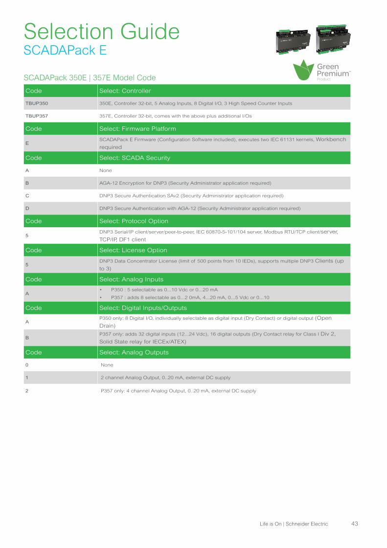
Selection GuideSCADAPack E
SCADAPack 350E | 357E Model Code
Code Select: Controller
TBUP350 350E, Controller 32-bit, 5 Analog Inputs, 8 Digital I/O, 3 High Speed Counter Inputs
TBUP357 357E, Controller 32-bit, comes with the above plus additional I/Os
Code Select: Firmware Platform
ESCADAPack E Firmware (Configuration Software included), executes two IEC 61131 kernels, Workbench
required
Code Select: SCADA Security
A None
B AGA-12 Encryption for DNP3 (Security Administrator application required)
C DNP3 Secure Authentication SAv2 (Security Administrator application required)
D DNP3 Secure Authentication with AGA-12 (Security Administrator application required)
Code Select: Protocol Option
5DNP3 Serial/IP client/server/peer-to-peer, IEC 60870-5-101/104 server, Modbus RTU/TCP client/server,
TCP/IP, DF1 client
Code Select: License Option
5DNP3 Data Concentrator License (limit of 500 points from 10 IEDs), supports multiple DNP3 Clients (up
to 3)
Code Select: Analog Inputs
A• P350 : 5 selectable as 0...10 Vdc or 0...20 mA
• P357 : adds 8 selectable as 0...2 0mA, 4...20 mA, 0...5 Vdc or 0...10
Code Select: Digital Inputs/Outputs
AP350 only: 8 Digital I/O, individually selectable as digital input (Dry Contact) or digital output (Open
Drain)
BP357 only: adds 32 digital inputs (12...24 Vdc), 16 digital outputs (Dry Contact relay for Class I Div 2,
Solid State relay for IECEx/ATEX)
Code Select: Analog Outputs
0 None
1 2 channel Analog Output, 0..20 mA, external DC supply
2 P357 only: 4 channel Analog Output, 0..20 mA, external DC supply
Life is On | Schneider Electric 43
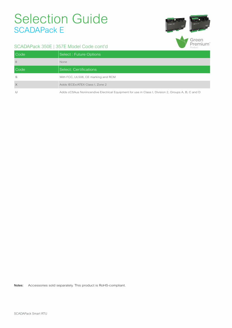
Selection GuideSCADAPack E
SCADAPack 350E | 357E Model Code cont'd
Code Select : Future Options
0 None
Code Select: Certifications
S With FCC, UL508, CE marking and RCM
X Adds IECEx/ATEX Class I, Zone 2
U Adds cCSAus Nonincendive Electrical Equipment for use in Class I, Division 2, Groups A, B, C and D
Notes: Accessories sold separately. This product is RoHS-compliant.
SCADAPack Smart RTU

Selection GuideSCADAPack E
SCADAPack 530E | 535E Specifications
Controller
Processor SPEAr 1380 32-bit dual-core Cortex A9 microcontroller, up to 600 MHz
Memory• 128 MB NAND FLASH, 128 MB DDR3 RAM
• Non-Volatile RAM CMOS SRAM with lithium battery retains contents for 2 years with no power
Event Logging Capacity
(events)40,000 (this number decreases if the database is greater than 10,000 points)
Database Capacity (points) Up to 20,000 (this number decreases if the event pool is above 7,000 events)
Data Concentrator
Capacity (points)Approximately 15,000
Data Concentrator
Capacity (devices) Approximately 100
File System Typical
Storage Internal: 10 MB; External: 32 GB (on optional memory stick)
Communications
Serial Ports: Serial1,
Serial2
RS-232 port, 8-pin modular RJ45 jack, full or half duplex with RTS/CTS control and operator interface
power control, supports baud rates up to 115,200 bps. Rated to ±15 kV (IEC 61000-4-2, Air
Discharge) static protection
Serial Ports: Serial3, Serial4
• RS-232 port, 8-pin modular RJ45 jack, full or half duplex, or RS-485 port, 2-wire, half-duplex,
supports baud rates up to 115,200 bps
• In RS-232 mode, rated to ±15 kV (IEC 61000-4-2, Air Discharge) static protection
Embedded Wireless • The controller board is fitted with Socket Modem support, for future use
Serial ProtocolsDNP3 level 4 server/client and peer-to-peer, IEC 60870-5-101 server, Modbus server/client, DF1
client
Ethernet Ports:
Eth1, Eth2, Eth38-pin modular RJ45 jack, 10/100 Mbps UTP (10/100 Base-T), transformer-isolated
IP Protocols
• DNP3 level 4 in TCP Client/Server, UDP Client/Server and peer-to-peer, IEC 60870-5-104 Server,
Modbus/TCP Server, Modbus/ TCP Client, Modbus RTU in TCP Client
• NTP Client/Server, Telnet Server, FTP Server, BOOTP Serve
Client - Server Capability
• Can simultaneously report to up to 29 independent clients (3 in DNP3, 2 in IEC 60870-5-5-101/104,
20 in Modbus TCP and 4 in Modbus RTU ) and connect to up to 100 remote devices in DNP3 peer-to-
peer
• As a data concentrator it can manage up to 100 local or remote DNP3 servers, and up to 100 local
servers communicating with Modbus RTU, Modbus TCP or DF1 serial
USB Device USB 2.0-compliant “B”-type receptacle, for local configuration
USB HostUSB 2.0-compliant “A”-type receptacle, supports USB devices up to 32GB (specific memory sticks
supported)
Life is On | Schneider Electric 45
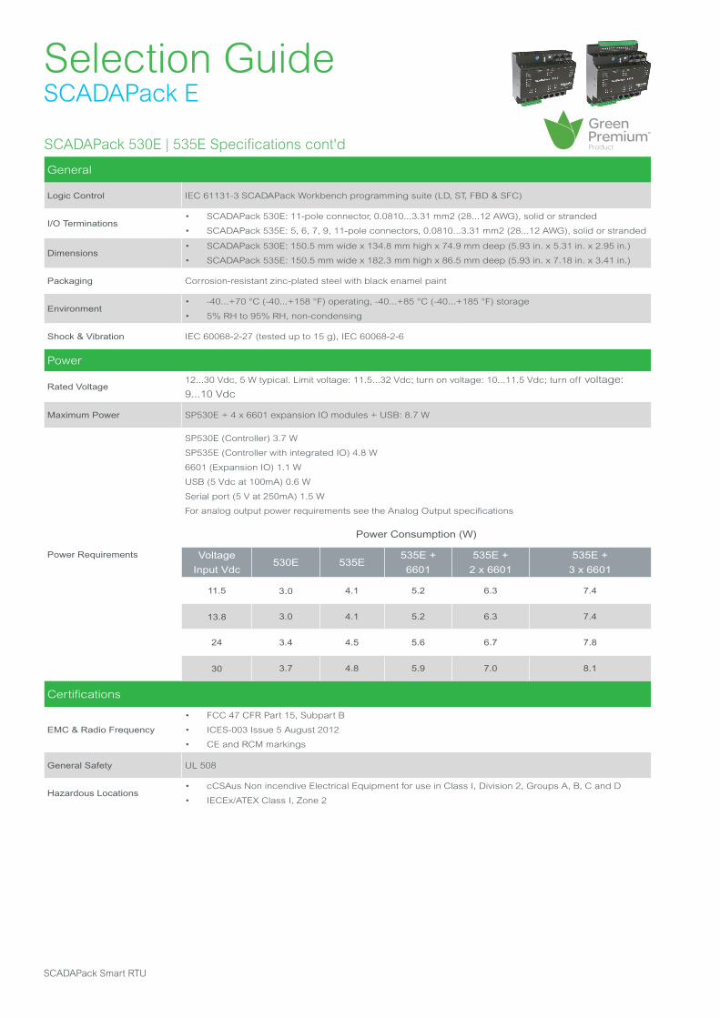
Selection GuideSCADAPack E
SCADAPack 530E | 535E Specifications cont'd
General
Logic Control IEC 61131-3 SCADAPack Workbench programming suite (LD, ST, FBD & SFC)
I/O Terminations• SCADAPack 530E: 11-pole connector, 0.0810...3.31 mm2 (28...12 AWG), solid or stranded
• SCADAPack 535E: 5, 6, 7, 9, 11-pole connectors, 0.0810...3.31 mm2 (28...12 AWG), solid or stranded
Dimensions• SCADAPack 530E: 150.5 mm wide x 134.8 mm high x 74.9 mm deep (5.93 in. x 5.31 in. x 2.95 in.)
• SCADAPack 535E: 150.5 mm wide x 182.3 mm high x 86.5 mm deep (5.93 in. x 7.18 in. x 3.41 in.)
Packaging Corrosion-resistant zinc-plated steel with black enamel paint
Environment• -40...+70 °C (-40...+158 °F) operating, -40...+85 °C (-40...+185 °F) storage
• 5% RH to 95% RH, non-condensing
Shock & Vibration IEC 60068-2-27 (tested up to 15 g), IEC 60068-2-6
Power
Rated Voltage12...30 Vdc, 5 W typical. Limit voltage: 11.5...32 Vdc; turn on voltage: 10...11.5 Vdc; turn off voltage:
9...10 Vdc
Maximum Power SP530E + 4 x 6601 expansion IO modules + USB: 8.7 W
Power Requirements
SP530E (Controller) 3.7 W
SP535E (Controller with integrated IO) 4.8 W
6601 (Expansion IO) 1.1 W
USB (5 Vdc at 100mA) 0.6 W
Serial port (5 V at 250mA) 1.5 W
For analog output power requirements see the Analog Output specifications
Power Consumption (W)
Voltage
Input Vdc530E 535E
535E +
6601
535E +
2 x 6601
535E +
3 x 6601
11.5 3.0 4.1 5.2 6.3 7.4
13.8 3.0 4.1 5.2 6.3 7.4
24 3.4 4.5 5.6 6.7 7.8
30 3.7 4.8 5.9 7.0 8.1
Certifications
EMC & Radio Frequency
• FCC 47 CFR Part 15, Subpart B
• ICES-003 Issue 5 August 2012
• CE and RCM markings
General Safety UL 508
Hazardous Locations • cCSAus Non incendive Electrical Equipment for use in Class I, Division 2, Groups A, B, C and D
• IECEx/ATEX Class I, Zone 2
SCADAPack Smart RTU
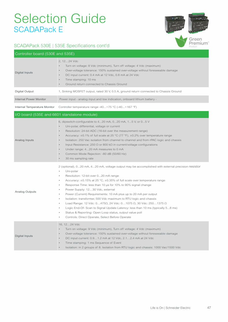
Selection GuideSCADAPack E
SCADAPack 530E | 535E Specifications cont'd
Controller board (530E and 535E)
Digital Inputs
2, 12…24 Vdc
• Turn on voltage: 8 Vdc (minimum), Turn off voltage: 4 Vdc (maximum)
• Over-voltage tolerance: 150% sustained over-voltage without foreseeable damage
• DC input current: 0.4 mA at 12 Vdc, 0.8 mA at 24 Vdc
• Time stamping: 10 ms
• Ground return connected to Chassis Ground
Digital Output 1, Sinking MOSFET output, rated 30 V, 0.5 A, ground return connected to Chassis Ground
Internal Power Monitor Power input - analog input and low indication, onboard lithium battery -
Internal Temperature Monitor Controller temperature range -40...+75 °C (-40...+167 °F)
I/O board (535E and 6601 standalone module)
Analog Inputs
6, dipswitch-configurable to 4...20 mA, 0...20 mA, 1...5 V, or 0...5 V
• Uni-polar, differential, voltage or current
• Resolution: 24-bit ADC (16-bit over the measurement range)
• Accuracy: ±0.1% of full scale at 25 °C (77 °F), ±0.2% over temperature range
• Isolation: 250 Vac isolation from channel to channel and from rPAC logic and chassis
• Input Resistance: 250 Ω or 800 kΩ in current/voltage configurations
• Under range: 4...20 mA measures to 0 mA
• Common Mode Rejection: -80 dB (50/60 Hz)
• 30 ms sampling rate
Analog Outputs
2 (optional), 0...20 mA, 4...20 mA, voltage output may be accomplished with external precision resistor
• Uni-polar
• Resolution: 12-bit over 0...20 mA range
• Accuracy: ±0.15% at 25 °C, ±0.35% of full scale over temperature range
• Response Time: less than 10 μs for 10% to 90% signal change
• Power Supply: 12…30 Vdc, external
• Power (Current) Requirements: 10 mA plus up to 20 mA per output
• Isolation: transformer, 500 Vdc maximum to RTU logic and chassis
• Load Range: 12 Vdc: 0…475Ω, 24 Vdc: 0…1075 Ω, 30 Vdc: 250…1375 Ω
• Logic End-Of- Scan to Signal Update Latency: less than 10 ms (typically 5...8 ms)
• Status & Reporting: Open Loop status, output value poll
• Controls: Direct Operate, Select Before Operate
Digital Inputs
16, 12…24 Vdc
• Turn on voltage: 9 Vdc (minimum), Turn off voltage: 4 Vdc (maximum)
• Over-voltage tolerance: 150% sustained over-voltage without foreseeable damage
• DC input current: 0.9…1.2 mA at 12 Vdc, 2.1…2.4 mA at 24 Vdc
• Time stamping: 1 ms Sequence of Event
• Isolation: in 2 groups of 8. Isolation from RTU logic and chassis: 1000 Vac/1500 Vdc
Life is On | Schneider Electric 47

Selection GuideSCADAPack E
SCADAPack 530E | 535E Specifications cont'd
I/O board (535E and 6601 standalone module) cont'd
Digital Outputs
8, relays (2 Form C, 6 Form A)
• Form C: SPDT, separate Normally Open/Normally Closed/Common
• Form A: Normally open, one common
• Isolation: 500 Vac minimum to RTU logic
• Maximum Switching Voltage: 30 Vdc or 25 Vac
• Maximum Switching Load: 60 W or 50 VA (2A)
• Status & Reporting: Individual relay pole feedback to software, output state poll
• Controls: Direct Operate, Select Before Operate, Trip/Close, Latch, Pulse
Counter Inputs 8, shared with digital input channels 1 to 4: 0…1.5 kHz, 5 to 8: 0…150 Hz
Additional I/O
I/O Expansion
Supported modules:
• 5304, 5405, 5414, 5415, 5506, 5606, 5607, 6601
Maximum number of modules per unit:
• SCADAPack 530E: 16*
• SCADAPack 535E: 15*
Footnote: * to reach this limit, additional power supply modules are required
SCADAPack Smart RTU
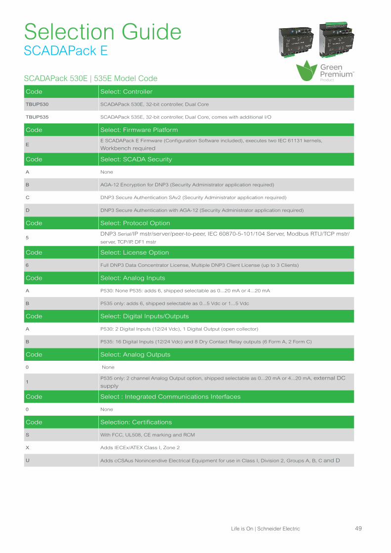
Selection GuideSCADAPack E
SCADAPack 530E | 535E Model Code
Code Select: Controller
TBUP530 SCADAPack 530E, 32-bit controller, Dual Core
TBUP535 SCADAPack 535E, 32-bit controller, Dual Core, comes with additional I/O
Code Select: Firmware Platform
EE SCADAPack E Firmware (Configuration Software included), executes two IEC 61131 kernels,
Workbench required
Code Select: SCADA Security
A None
B AGA-12 Encryption for DNP3 (Security Administrator application required)
C DNP3 Secure Authentication SAv2 (Security Administrator application required)
D DNP3 Secure Authentication with AGA-12 (Security Administrator application required)
Code Select: Protocol Option
5DNP3 Serial/IP mstr/server/peer-to-peer, IEC 60870-5-101/104 Server, Modbus RTU/TCP mstr/
server, TCP/IP, DF1 mstr
Code Select: License Option
6 Full DNP3 Data Concentrator License, Multiple DNP3 Client License (up to 3 Clients)
Code Select: Analog Inputs
A P530: None P535: adds 6, shipped selectable as 0...20 mA or 4...20 mA
B P535 only: adds 6, shipped selectable as 0...5 Vdc or 1...5 Vdc
Code Select: Digital Inputs/Outputs
A P530: 2 Digital Inputs (12/24 Vdc), 1 Digital Output (open collector)
B P535: 16 Digital Inputs (12/24 Vdc) and 8 Dry Contact Relay outputs (6 Form A, 2 Form C)
Code Select: Analog Outputs
0 None
1P535 only: 2 channel Analog Output option, shipped selectable as 0...20 mA or 4...20 mA, external DC
supply
Code Select : Integrated Communications Interfaces
0 None
Code Selection: Certifications
S With FCC, UL508, CE marking and RCM
X Adds IECEx/ATEX Class I, Zone 2
U Adds cCSAus Nonincendive Electrical Equipment for use in Class I, Division 2, Groups A, B, C and D
Life is On | Schneider Electric 49

Selection GuideSCADAPack E
I/O Expansion Modules (Supported by SCADAPack 530E & 535E Controllers only)Model Codes
Part No.I/O Expansion Modules (complete the following part numbers with S, U or X depending on
certification required)
TBUX297583___ Model 6601-20 mA, 16 D/I 12...24 Vdc, 8 Dry Contact relay O/P, 6 config. A/I (0/4...20 mA)
TBUX297584___ Model 6601-5 V, 16 D/I 12...24 Vdc, 8 Dry Contact relay O/P, 6 config. A/I (0/1...5 Vdc)
TBUX297585___
Model 6601-20 mA, 16 D/I 12...24 Vdc, 8 Dry Contact relay O/P, 6 config. A/I (0/4...20 mA), 2 A/O (external
DC
supply)
TBUX297586___Model 6601-5 V, 16 D/I 12...24 Vdc, 8 Dry Contact relay O/P, 6 config. A/I (0/1...5 Vdc), 2 A/O (external DC
supply)
I/O expansion and distributed architecture
1. Depending on the options chosen (with or without the future socket modem), SCADAPack 535E embedded DC supply can power
either two (2) or four (4) 6601 IO expansion modules. When more 6601 IO expansion modules are required in any of
these two configurations, then it is necessary to use one of our power supply extensions (one unit can power up to 8x
6601 modules).
2. SCADAPack 535E can be used as a Remote I/O client, managing up to 15 SCADAPack ES server units: SCADAPack 535E
automatically downloads the corresponding configuration into these server devices (which is very useful when replacing
devices, as the operator does not have to do any firmware setting).
Notes: Accessories sold separately. This product is RoHS-compliant.
SCADAPack Smart RTUSCADAPack Smart RTU

Selection GuideI/O Expansion Modules
5103 Uninterruptible Power Supply Specifications
General
AC/DC Input• 16...24 Vac for 5/24 Vdc outputs operational, 24 Vac required for battery charging
• 14.5+/-0.5 Vdc for 5/24 Vdc outputs operational, 20 Vdc required for battery charging
DC/Battery Input Turn on at 11.5 Vdc ± 0.3 Vdc, Turn off at 10.5 Vdc ± 0.5 Vdc, Maximum input is 36 Vdc
Input Power 35 VA maximum at 24 Vac, 1.9 A at 13.5 Vdc
Outputs
5 Vdc at 2.0 A, 24 Vdc at 0.5 A, 17 W total available from the two outputs
11...14 Vdc battery charger at 200 mA (factory adjusted to 13.5 Vdc for gelled electrolyte lead/acid
battery)
Mode Isolated switch-mode, 30 KHz switch frequency
Line Regulation < 1% over operating range
Load Regulation• 5 Vdc output: 5.15 Vdc ±1% over operating range
• 24 Vdc output: ±17%
Output Ripple• 5 Vdc output: < 10 mV at 20 °C (68 °F)
• 24 Vdc output: < 50 mV at 20 °C (68 °F)
Visual Indicators 5 Vdc and 24 Vdc green LEDs show power status
Power Requirements 35 VA maximum @ 24 Vac, 1.9 A @ 13.5 Vdc
Terminations 10-pole, removable terminal block, 12...22 AWG, 15 amp contacts
Dimensions 108 mm wide x 118 mm high x 44 mm deep (4.25 in. x 4.625 in. x 1.75 in.)
Mounting 7.5 x 35 DIN rail
Packaging Corrosion-resistant zinc plated steel with black enamel paint
Environment• 5% RH to 95% RH, non-condensing
• -40...+60 °C (-40...+140 °F)
Safety
Non-Incendive Electrical Equipment for Use in Class I, Division 2 Groups A, B, C and D
Hazardous Locations.
Temperature Code T4 at 60 °C ambient. UL Listed to the following standards:
• CSA Std. C22.2 No. 213-M1987 - Hazardous Locations
• CSA Std. C22.2 No. 142-M1987 - Process Control Equipment
• UL Std. No. 1604 - Hazardous (Classified) Locations
• UL Std. No. 508 - Industrial Control Equipment
5103 Uninterruptible Power Supply Model Code
Part Number Model Description
TBUX297102 5103 SCADAPack Uninterruptible power supply
Accessories
Part Number Model Description
TBUX294034 1206 12 Vdc 6 AH gelled electrolyte battery
TBUX294000 ACX-24 120/24 Vac, 40 VA transformer
TBUX294167 ACX-24E 220/24 Vac, 40 VA transformer
Notes: Accessories sold separately. This product is RoHS-compliant.
Some I/O Expansion modules are specific to SCADAPack 300 RTUs, others are specific to SCADAPack E RTUs.
Life is On | Schneider Electric 51
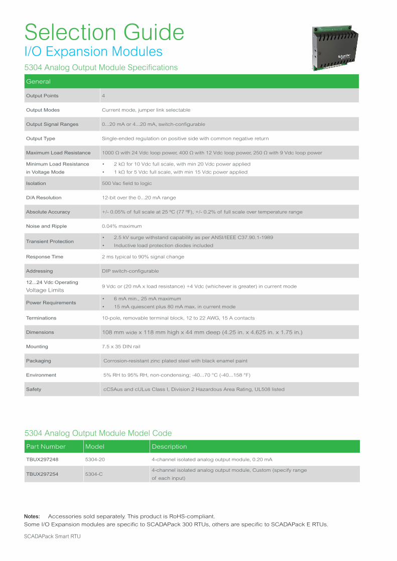
Selection GuideI/O Expansion Modules5304 Analog Output Module Specifications
General
Output Points 4
Output Modes Current mode, jumper link selectable
Output Signal Ranges 0...20 mA or 4...20 mA, switch-configurable
Output Type Single-ended regulation on positive side with common negative return
Maximum Load Resistance 1000 Ω with 24 Vdc loop power, 400 Ω with 12 Vdc loop power, 250 Ω with 9 Vdc loop power
Minimum Load Resistance
in Voltage Mode
• 2 kΩ for 10 Vdc full scale, with min 20 Vdc power applied
• 1 kΩ for 5 Vdc full scale, with min 15 Vdc power applied
Isolation 500 Vac field to logic
D/A Resolution 12-bit over the 0...20 mA range
Absolute Accuracy +/- 0.05% of full scale at 25 ºC (77 ºF), +/- 0.2% of full scale over temperature range
Noise and Ripple 0.04% maximum
Transient Protection • 2.5 kV surge withstand capability as per ANSI/IEEE C37.90.1-1989
• Inductive load protection diodes included
Response Time 2 ms typical to 90% signal change
Addressing DIP switch-configurable
12...24 Vdc Operating
Voltage Limits9 Vdc or (20 mA x load resistance) +4 Vdc (whichever is greater) in current mode
Power Requirements• 6 mA min., 25 mA maximum
• 15 mA quiescent plus 80 mA max. in current mode
Terminations 10-pole, removable terminal block, 12 to 22 AWG, 15 A contacts
Dimensions 108 mm wide x 118 mm high x 44 mm deep (4.25 in. x 4.625 in. x 1.75 in.)
Mounting 7.5 x 35 DIN rail
Packaging Corrosion-resistant zinc plated steel with black enamel paint
Environment 5% RH to 95% RH, non-condensing; -40...70 °C (-40...158 °F)
Safety cCSAus and cULus Class I, Division 2 Hazardous Area Rating, UL508 listed
5304 Analog Output Module Model Code
Part Number Model Description
TBUX297248 5304-20 4-channel isolated analog output module, 0.20 mA
TBUX297254 5304-C4-channel isolated analog output module, Custom (specify range
of each input)
Notes: Accessories sold separately. This product is RoHS-compliant.
Some I/O Expansion modules are specific to SCADAPack 300 RTUs, others are specific to SCADAPack E RTUs.
SCADAPack Smart RTU

Selection GuideI/O Expansion Modules5401 Configurable Digital I/O Module Specifications
General
Number of Inputs or Outputs 8
Voltage Range See relay specifications below
Load Current See relay specifications below
Surge Current See relay specifications below
Off-State Leakage See relay specifications below
Transient Protection Integral to the solid-state relay
Response Time See relay specifications below
Isolation 1500 Vac
Addressing DIP switch-configurable
Input/Output Assignment DIP switch selection for each I/O point
Power Requirements 5 Vdc @ 90 mA
Visual Indicators 8: LEDs
Field Terminations 2: 8-pole, removable terminal block, 12...22 AWG, 15 A contacts
Dimensions 108 mm wide x 118 mm high x 44 mm deep (4.25 in. x 4.625 in. x 1.75 in.)l
Mounting 7.5 x 35 DIN rail
Packaging Corrosion-resistant zinc plated steel with black enamel paint
Environment 5% RH to 95% RH, non-condensing, –40...60 °C or (–40...140 °F)
Safety cCSAus and cULus Class I, Division 2 Hazardous Area Rating, UL508 listed
5401 Configurable Digital I/O Module Model Code
Part Number Model Solid-State Relays for use with Model 5401
TBUM297122 IACM-5 90...140 Vac/Vdc input relay
TBUM297132 IACM-5A 180...280 Vac/Vdc input relay
TBUM297133 IACM-5E 10...32 Vdc, 15...32 Vac, no polarity
TBUM297124 IDCM-5 3...32 Vdc input relay
TBUM297123 OACM-5 24...140 Vac output relay, 3 A
TBUM297134 OACM-5H 24...280 Vac output relay, 5 A
TBUM297125 ODCM-5 3...60 Vdc output relay, 3 A
TBUM297135 ODCM-5A 10...200 Vdc, 1 A
Part Number Model Description
TBUX297121 5401 8-point input or output module (requires solid-state relays)
Notes: Accessories sold separately. This product is not RoHS-compliant.
Some I/O Expansion modules are specific to SCADAPack 300 RTUs, others are specific to SCADAPack E RTUs.
Life is On | Schneider Electric 53
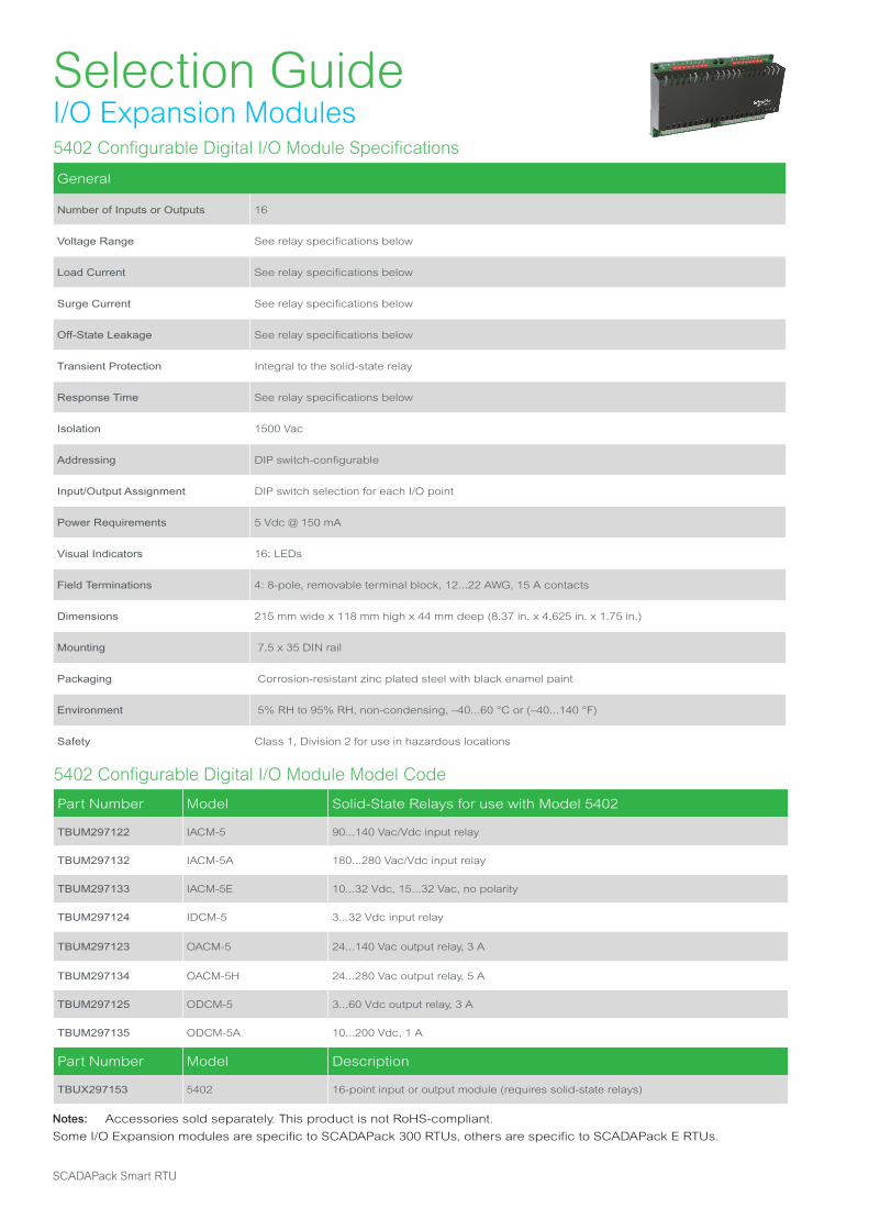
Selection GuideI/O Expansion Modules5402 Configurable Digital I/O Module Specifications
General
Number of Inputs or Outputs 16
Voltage Range See relay specifications below
Load Current See relay specifications below
Surge Current See relay specifications below
Off-State Leakage See relay specifications below
Transient Protection Integral to the solid-state relay
Response Time See relay specifications below
Isolation 1500 Vac
Addressing DIP switch-configurable
Input/Output Assignment DIP switch selection for each I/O point
Power Requirements 5 Vdc @ 150 mA
Visual Indicators 16: LEDs
Field Terminations 4: 8-pole, removable terminal block, 12...22 AWG, 15 A contacts
Dimensions 215 mm wide x 118 mm high x 44 mm deep (8.37 in. x 4.625 in. x 1.75 in.)
Mounting 7.5 x 35 DIN rail
Packaging Corrosion-resistant zinc plated steel with black enamel paint
Environment 5% RH to 95% RH, non-condensing, –40...60 °C or (–40...140 °F)
Safety Class 1, Division 2 for use in hazardous locations
5402 Configurable Digital I/O Module Model Code
Part Number Model Solid-State Relays for use with Model 5402
TBUM297122 IACM-5 90...140 Vac/Vdc input relay
TBUM297132 IACM-5A 180...280 Vac/Vdc input relay
TBUM297133 IACM-5E 10...32 Vdc, 15...32 Vac, no polarity
TBUM297124 IDCM-5 3...32 Vdc input relay
TBUM297123 OACM-5 24...140 Vac output relay, 3 A
TBUM297134 OACM-5H 24...280 Vac output relay, 5 A
TBUM297125 ODCM-5 3...60 Vdc output relay, 3 A
TBUM297135 ODCM-5A 10...200 Vdc, 1 A
Part Number Model Description
TBUX297153 5402 16-point input or output module (requires solid-state relays)
Notes: Accessories sold separately. This product is not RoHS-compliant.
Some I/O Expansion modules are specific to SCADAPack 300 RTUs, others are specific to SCADAPack E RTUs.
SCADAPack Smart RTU

Selection GuideI/O Expansion Modules5403 High Level Digital Input Module Specifications
General
Number of Inputs or Outputs 8
Voltage Range OFF to ON transition threshold is typically 50% of full scale signal range
Over-Voltage Tolerance 150% sustained over-voltage without damage
Input Current 5 mA typical
Response Time• OFF to ON: 7 ms typical
• ON to OFF: 24 ms typical
Isolation 1500 Vac in groups of 4 inputs
Addressing DIP switch-configurable
Power Requirements 5 Vdc @ 45 mA all LEDs ON, 5 Vdc @ 25 mA with LEDs disabled
Visual Indicators 8: LEDs controlled for power reduction
Field Terminations
• 1: 10-pole, removable terminal block
• 12...2 AWG
• 15 A contacts
Dimensions 108 mm wide x 118 mm high x 44 mm deep (4.25 in. x 4.625 in. x 1.75 in.)
Mounting 7.5 x 35 DIN rail
Packaging Corrosion-resistant zinc plated steel with black enamel paint
Environment 5% RH to 95% RH, non-condensing, –40...60 °C or (–40...140 °F)
Safety cCSAus and cULus Class I, Division 2 Hazardous Area Rating, UL508 listed
5403 High Level Digital Input Module Model Code
Part Number Model Signal Range
TBUX297110 5403-12 12 Vac, Vdc
TBUX297109 5403-24 24 Vac, Vdc
TBUX297106 5403-240 240 Vac, Vdc
Notes: Accessories sold separately. This product is RoHS-compliant.
Some I/O Expansion modules are specific to SCADAPack 300 RTUs, others are specific to SCADAPack E RTUs.
Life is On | Schneider Electric 55
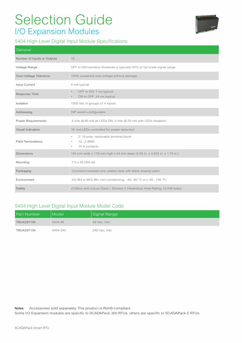
Selection GuideI/O Expansion Modules5404 High Level Digital Input Module Specifications
General
Number of Inputs or Outputs 16
Voltage Range OFF to ON transition threshold is typically 50% of full scale signal range
Over-Voltage Tolerance 150% sustained over-voltage without damage
Input Current 5 mA typical
Response Time• OFF to ON: 7 ms typical
• ON to OFF: 24 ms typical
Isolation 1500 Vac in groups of 4 inputs
Addressing DIP switch-configurable
Power Requirements 5 Vdc @ 80 mA all LEDs ON, 5 Vdc @ 25 mA with LEDs disabled
Visual Indicators 16: red LEDs controlled for power reduction
Field Terminations
• 2: 10-pole, removable terminal block
• 12...2 AWG
• 15 A contacts
Dimensions 144 mm wide x 118 mm high x 44 mm deep (5.65 in. x 4.625 in. x 1.75 in.)
Mounting 7.5 x 35 DIN rail
Packaging Corrosion-resistant zinc plated steel with black enamel paint
Environment 5% RH to 95% RH, non-condensing, –40...60 °C or (–40...140 °F)
Safety cCSAus and cULus Class I, Division 2 Hazardous Area Rating, UL508 listed
5404 High Level Digital Input Module Model Code
Part Number Model Signal Range
TBUX297156 5404-48 48 Vac, Vdc
TBUX297154 5404-240 240 Vac, Vdc
Notes: Accessories sold separately. This product is RoHS-compliant.
Some I/O Expansion modules are specific to SCADAPack 300 RTUs, others are specific to SCADAPack E RTUs.
SCADAPack Smart RTU

Selection GuideI/O Expansion Modules5405 Digital Input Module Specifications
General
Number of Inputs or Outputs 32
Ranges 12...24 Vdc, 16...24 Vac, 120 Vac/Vdc
Over-Voltage Tolerance 150% sustained over-voltage without damage
Input Current
• 6.0 mA typical @ 24 Vdc on the 24 Vdc range
• 3.5 mA typical @ 24 Vac on the 24 Vac range
• 2.5 mA typical @ 120 Vdc on the 120 Vdc range
• 1.5 mA typical @ 120 Vac on the 120 Vac range
DC Input Logic Levels• OFF to ON transition threshold is typically 7.5 Vdc on the 24 Vdc range
• OFF to ON transition threshold is typically 55 Vdc on the 120 Vdc range
AC Input Levels• OFF to ON transition threshold is typically 6 Vac on the 24 Vac range
• OFF to ON transition threshold is typically 45 Vac on the 120 Vac range
Transient Protection 2.5 kV surge withstand capability as per ANSI/IEEE C37.90.1-1989
Isolation• Isolated in 4 groups of 8. Inputs 0...15 are on the bottom edge
• Inputs 16...31 are on the top edge. Isolation 500 Vac/Vdc from chassis and logic ground
Power Requirements 5 Vdc @ 10 mA with all inputs ON
Terminations 4: 9-pole, removable terminal blocks, 12 to 22 AWG, 15 A contacts
Dimensions 144 mm wide x 127 mm high x 45 mm deep (5.65 in. x 5.00 in. x 1.88 in.)
Packaging Corrosion-resistant zinc plated steel with black enamel paint
Environment 5% RH to 95% RH, non-condensing, –40...60 °C or (–40...140 °F)
Addressing Configurable with 4 DIP switches
AC/DC Operation 2: DIP switches determine AC/DC and 50/60 Hz operation
Visual Indicators 32: Red LED’s, field powered. Cannot be disabled to conserve power
Safety cCSAus and cULus Class I, Division 2 Hazardous Area Rating, UL508 listed
5405 Digital Input Module Model Code
Part Number Model Description
TBUX297249 5405-120 32-point, 120 Vac discrete input module
TBUX297247 5405-24 32-point, 12...24 Vdc discrete input module
Notes: Accessories sold separately. This product is RoHS-compliant.
Some I/O Expansion modules are specific to SCADAPack 300 RTUs, others are specific to SCADAPack E RTUs.
Life is On | Schneider Electric 57
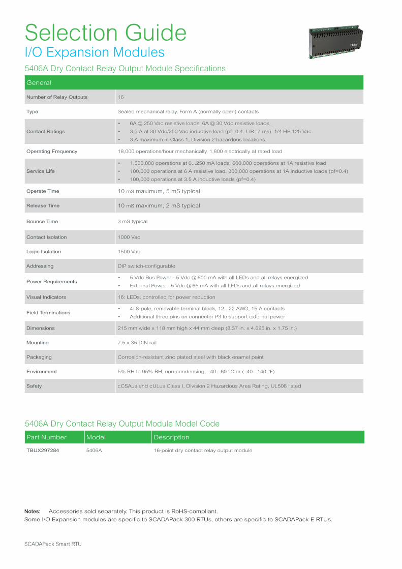
Selection GuideI/O Expansion Modules5406A Dry Contact Relay Output Module Specifications
General
Number of Relay Outputs 16
Type Sealed mechanical relay, Form A (normally open) contacts
Contact Ratings
• 6A @ 250 Vac resistive loads, 6A @ 30 Vdc resistive loads
• 3.5 A at 30 Vdc/250 Vac inductive load (pf=0.4. L/R=7 ms), 1/4 HP 125 Vac
• 3 A maximum in Class 1, Division 2 hazardous locations
Operating Frequency 18,000 operations/hour mechanically, 1,800 electrically at rated load
Service Life
• 1,500,000 operations at 0...250 mA loads, 600,000 operations at 1A resistive load
• 100,000 operations at 6 A resistive load, 300,000 operations at 1A inductive loads (pf=0.4)
• 100,000 operations at 3.5 A inductive loads (pf=0.4)
Operate Time 10 mS maximum, 5 mS typical
Release Time 10 mS maximum, 2 mS typical
Bounce Time 3 mS typical
Contact Isolation 1000 Vac
Logic Isolation 1500 Vac
Addressing DIP switch-configurable
Power Requirements• 5 Vdc Bus Power - 5 Vdc @ 600 mA with all LEDs and all relays energized
• External Power - 5 Vdc @ 65 mA with all LEDs and all relays energized
Visual Indicators 16: LEDs, controlled for power reduction
Field Terminations• 4: 8-pole, removable terminal block, 12...22 AWG, 15 A contacts
• Additional three pins on connector P3 to support external power
Dimensions 215 mm wide x 118 mm high x 44 mm deep (8.37 in. x 4.625 in. x 1.75 in.)
Mounting 7.5 x 35 DIN rail
Packaging Corrosion-resistant zinc plated steel with black enamel paint
Environment 5% RH to 95% RH, non-condensing, –40...60 °C or (–40...140 °F)
Safety cCSAus and cULus Class I, Division 2 Hazardous Area Rating, UL508 listed
5406A Dry Contact Relay Output Module Model Code
Part Number Model Description
TBUX297284 5406A 16-point dry contact relay output module
Notes: Accessories sold separately. This product is RoHS-compliant.
Some I/O Expansion modules are specific to SCADAPack 300 RTUs, others are specific to SCADAPack E RTUs.
SCADAPack Smart RTU
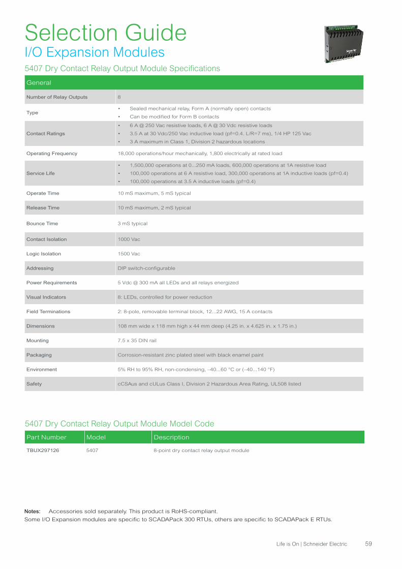
Selection GuideI/O Expansion Modules5407 Dry Contact Relay Output Module Specifications
General
Number of Relay Outputs 8
Type• Sealed mechanical relay, Form A (normally open) contacts
• Can be modified for Form B contacts
Contact Ratings
• 6 A @ 250 Vac resistive loads, 6 A @ 30 Vdc resistive loads
• 3.5 A at 30 Vdc/250 Vac inductive load (pf=0.4. L/R=7 ms), 1/4 HP 125 Vac
• 3 A maximum in Class 1, Division 2 hazardous locations
Operating Frequency 18,000 operations/hour mechanically, 1,800 electrically at rated load
Service Life
• 1,500,000 operations at 0...250 mA loads, 600,000 operations at 1A resistive load
• 100,000 operations at 6 A resistive load, 300,000 operations at 1A inductive loads (pf=0.4)
• 100,000 operations at 3.5 A inductive loads (pf=0.4)
Operate Time 10 mS maximum, 5 mS typical
Release Time 10 mS maximum, 2 mS typical
Bounce Time 3 mS typical
Contact Isolation 1000 Vac
Logic Isolation 1500 Vac
Addressing DIP switch-configurable
Power Requirements 5 Vdc @ 300 mA all LEDs and all relays energized
Visual Indicators 8: LEDs, controlled for power reduction
Field Terminations 2: 8-pole, removable terminal block, 12...22 AWG, 15 A contacts
Dimensions 108 mm wide x 118 mm high x 44 mm deep (4.25 in. x 4.625 in. x 1.75 in.)
Mounting 7.5 x 35 DIN rail
Packaging Corrosion-resistant zinc plated steel with black enamel paint
Environment 5% RH to 95% RH, non-condensing, –40...60 °C or (–40...140 °F)
Safety cCSAus and cULus Class I, Division 2 Hazardous Area Rating, UL508 listed
5407 Dry Contact Relay Output Module Model Code
Part Number Model Description
TBUX297126 5407 8-point dry contact relay output module
Notes: Accessories sold separately. This product is RoHS-compliant.
Some I/O Expansion modules are specific to SCADAPack 300 RTUs, others are specific to SCADAPack E RTUs.
Life is On | Schneider Electric 59
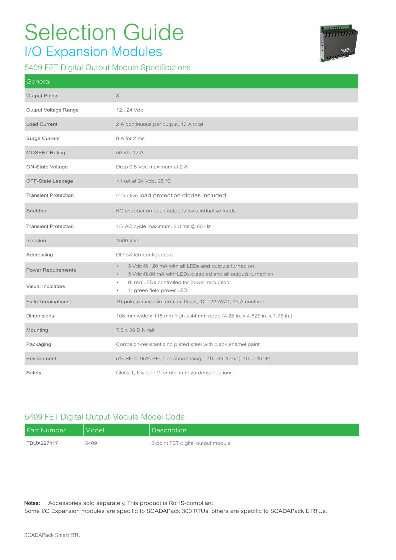
Selection GuideI/O Expansion Modules5409 FET Digital Output Module Specifications
General
Output Points 8
Output Voltage Range 12...24 Vdc
Load Current 2 A continuous per output, 10 A total
Surge Current 8 A for 2 ms
MOSFET Rating 50 Vc, 12 A
ON-State Voltage Drop 0.5 Vdc maximum at 2 A
OFF-State Leakage <1 uA at 24 Vdc, 25 °C
Transient Protection Inductive load protection diodes included
Snubber RC snubber on each output allows inductive loads
Transient Protection 1/2 AC cycle maximum, 8.3 ms @ 60 Hz
Isolation 1500 Vac
Addressing DIP switch-configurable
Power Requirements• 5 Vdc @ 120 mA with all LEDs and outputs turned on
• 5 Vdc @ 80 mA with LEDs disabled and all outputs turned on
Visual Indicators• 8: red LEDs controlled for power reduction
• 1: green field power LED
Field Terminations 10-pole, removable terminal block, 12...22 AWG, 15 A contacts
Dimensions 108 mm wide x 118 mm high x 44 mm deep (4.25 in. x 4.625 in. x 1.75 in.)
Mounting 7.5 x 35 DIN rail
Packaging Corrosion-resistant zinc plated steel with black enamel paint
Environment 5% RH to 95% RH, non-condensing, –40...60 °C or (–40...140 °F)
Safety Class 1, Division 2 for use in hazardous locations
5409 FET Digital Output Module Model Code
Part Number Model Description
TBUX297117 5409 8-point FET digital output module
Notes: Accessories sold separately. This product is RoHS-compliant.
Some I/O Expansion modules are specific to SCADAPack 300 RTUs, others are specific to SCADAPack E RTUs.
SCADAPack Smart RTU
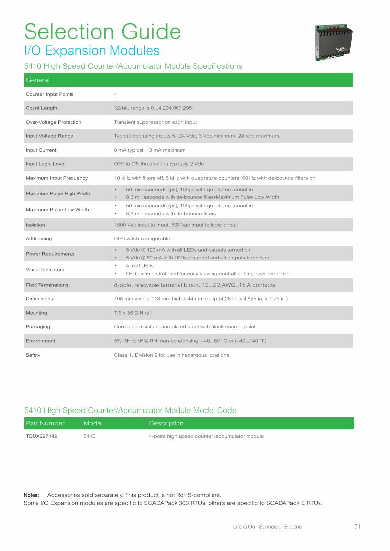
Selection GuideI/O Expansion Modules5410 High Speed Counter/Accumulator Module Specifications
General
Counter Input Points 4
Count Length 32-bit, range is 0...4,294,967,295
Over-Voltage Protection Transient suppressor on each input
Input Voltage Range Typical operating inputs 5...24 Vdc, 3 Vdc minimum, 28 Vdc maximum
Input Current 8 mA typical, 13 mA maximum
Input Logic Level OFF to ON threshold is typically 2 Vdc
Maximum Input Frequency 10 kHz with filters off, 5 kHz with quadrature counters, 60 Hz with de-bounce filters on
Maximum Pulse High Width• 50 microseconds (μs), 100μs with quadrature counters
• 8.3 milliseconds with de-bounce filtersMaximum Pulse Low Width
Maximum Pulse Low Width• 50 microseconds (μs), 100μs with quadrature counters
• 8.3 milliseconds with de-bounce filters
Isolation 1500 Vac input to input, 500 Vac input to logic circuit
Addressing DIP switch-configurable
Power Requirements• 5 Vdc @ 120 mA with all LEDs and outputs turned on
• 5 Vdc @ 80 mA with LEDs disabled and all outputs turned on
Visual Indicators• 4: red LEDs
• LED on time stretched for easy viewing controlled for power reduction
Field Terminations 8-pole, removable terminal block, 12...22 AWG, 15 A contacts
Dimensions 108 mm wide x 118 mm high x 44 mm deep (4.25 in. x 4.625 in. x 1.75 in.)
Mounting 7.5 x 35 DIN rail
Packaging Corrosion-resistant zinc plated steel with black enamel paint
Environment 5% RH to 95% RH, non-condensing, –40...60 °C or (–40...140 °F)
Safety Class 1, Division 2 for use in hazardous locations
5410 High Speed Counter/Accumulator Module Model Code
Part Number Model Description
TBUX297149 5410 4-point high speed counter /accumulator module
Notes: Accessories sold separately. This product is not RoHS-compliant.
Some I/O Expansion modules are specific to SCADAPack 300 RTUs, others are specific to SCADAPack E RTUs.
Life is On | Schneider Electric 61

Selection GuideI/O Expansion Modules5411 Digital Output Module Specifications
General
Output Points 32
Output Rating
• 1.0 A maximum
• 0.35 Vdc maximum drop at 1.0 A
• 0.05 Vdc maximum drop at 0.1 A
Transient Protection• 2.5 kV surge withstand capability as per ANSI/IEEE C37.90.1-1989
• Inductive load protection diodes included
Isolation• Isolated in 2 groups of 16
• Isolation 500 Vac/Vdc from chassis and logic ground
Power Requirements
• 5 Vdc @ 150 mA with all LEDs and outputs turned on
• 5 Vdc @ 40 mA with all LEDs disabled and all outputs turned on
• 24 Vdc @ 5 mA with all outputs ON
• 8 Vdc min., 30 Vdc max
Visual Indicators 32: Red LEDs, can be disabled to conserve power
Field Terminations• 2: 9 and two 10-pole, removable terminal blocks
• 12...22 AWG, 15 A contacts
Dimensions 144 mm wide x 127 mm high x 45 mm deep (5.65 in. x 5.00 in. x 1.80 in.)
Mounting 7.5 x 35 DIN rail
Packaging Corrosion-resistant zinc plated steel with black enamel paint
Environment 5% RH to 95% RH, non-condensing; -40...70 °C (-40...158 °F)
Safety cCSAus and cULus Class I, Division 2 Hazardous Area Rating, UL508 listed
5411 Digital Output Module Model Code
Part Number Model Description
TBUX297246 5411 32-point digital output module
Notes: Accessories sold separately. This product is RoHS-compliant.
Some I/O Expansion modules are specific to SCADAPack 300 RTUs, others are specific to SCADAPack E RTUs.
SCADAPack Smart RTU
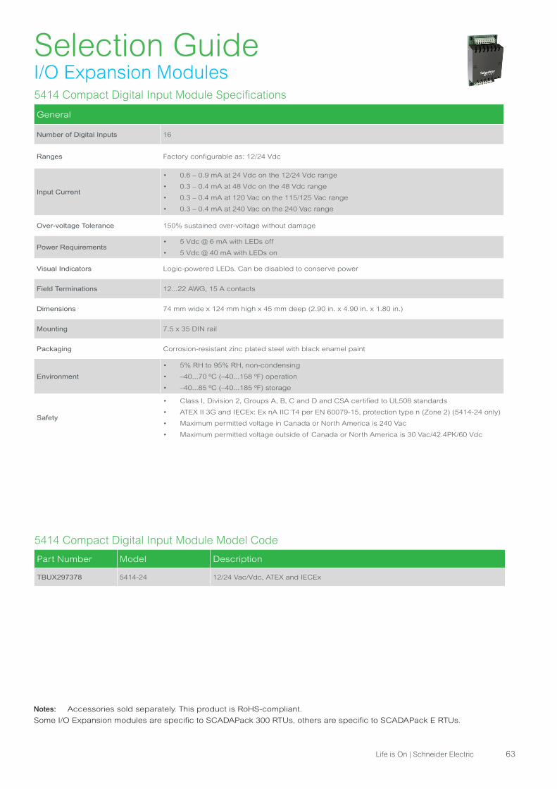
Selection GuideI/O Expansion Modules5414 Compact Digital Input Module Specifications
General
Number of Digital Inputs 16
Ranges Factory configurable as: 12/24 Vdc
Input Current
• 0.6 – 0.9 mA at 24 Vdc on the 12/24 Vdc range
• 0.3 – 0.4 mA at 48 Vdc on the 48 Vdc range
• 0.3 – 0.4 mA at 120 Vac on the 115/125 Vac range
• 0.3 – 0.4 mA at 240 Vac on the 240 Vac range
Over-voltage Tolerance 150% sustained over-voltage without damage
Power Requirements• 5 Vdc @ 6 mA with LEDs off
• 5 Vdc @ 40 mA with LEDs on
Visual Indicators Logic-powered LEDs. Can be disabled to conserve power
Field Terminations 12...22 AWG, 15 A contacts
Dimensions 74 mm wide x 124 mm high x 45 mm deep (2.90 in. x 4.90 in. x 1.80 in.)
Mounting 7.5 x 35 DIN rail
Packaging Corrosion-resistant zinc plated steel with black enamel paint
Environment
• 5% RH to 95% RH, non-condensing
• –40...70 ºC (–40...158 ºF) operation
• –40...85 ºC (–40...185 ºF) storage
Safety
• Class I, Division 2, Groups A, B, C and D and CSA certified to UL508 standards
• ATEX II 3G and IECEx: Ex nA IIC T4 per EN 60079-15, protection type n (Zone 2) (5414-24 only)
• Maximum permitted voltage in Canada or North America is 240 Vac
• Maximum permitted voltage outside of Canada or North America is 30 Vac/42.4PK/60 Vdc
5414 Compact Digital Input Module Model Code
Part Number Model Description
TBUX297378 5414-24 12/24 Vac/Vdc, ATEX and IECEx
Notes: Accessories sold separately. This product is RoHS-compliant.
Some I/O Expansion modules are specific to SCADAPack 300 RTUs, others are specific to SCADAPack E RTUs.
Life is On | Schneider Electric 63

Selection GuideI/O Expansion Modules5415 Compact Digital Output Module Specifications
General
Number of Digital Outputs 12
Type• Form A Contacts (Normally open), Dry Contact or Solid State Relay variants
• 4 contacts per common
Contact Rating
• 12 A maximum per common
• Dry Contact Version: 3 A, 30 Vdc or 250 Vac (Resistive)
• Solid State Relay Version: 60 Vdc max., 3 A max. at 50 °C (122 °F), 2 A max. at 70 °C (158 °F)
Switching Capacity
(Dry Contact Version)
• 5 A, 30 Vdc (150 W Resistive)
• 5 A X 250 Vac (1250 VA Resistive)
5 V Power Requirements
• 5 mA Quiescent
• Dry Contact version: 280 mA relays on, LEDs on
• 260 mA relays on, LEDs off
• Solid State Relay version: Relays on, LEDs on - 144 mA
• Relays on, LEDs off - 120 mA
10-30 Vdc
Power Requirements
• Dry Contact version: 1.0 W maximum with 1.65 W peak for 15 ms durations
• Solid State Relay version: 1.0 W maximum
Visual Indicators Logic-powered LEDs. Can be disabled to conserve power
Field Terminations 12...22 AWG, 15 A contacts
Dimensions 74 mm wide x 124 mm high x 45 mm deep (2.90 in. x 4.90 in. x 1.80 in.)
Mounting 7.5 x 35 DIN rail
Packaging Corrosion-resistant zinc plated steel with black enamel paint
Environment
• 5% RH to 95% RH, non-condensing
• –40...70 ºC (–40...158 ºF) operation
• –40...85 ºC (–40...185 ºF) storage
Safety
• Class I, Division 2, Groups A, B, C and D and CSA certified to UL508 standards
• ATEX II 3G and IECEx: Ex nA IIC T4 per EN 60079-15, protection type n (Zone 2) (5415-A only)
• Maximum permitted voltage in Canada or North America is 240 Vac
• Maximum permitted voltage outside of Canada or North America is 30 Vac/42.4 PK/60 Vdc
5415 Compact Digital Output Module Model Code
Part Number Model Description
TBUX297382 5415 12-Point Compact Mechanical Relay Output Module
TBUX297384 5415-A12-Point Compact Solid-State Relay Output Module, ATEX
and IECEx
Notes: Accessories sold separately. This product is RoHS-compliant.
Some I/O Expansion modules are specific to SCADAPack 300 RTUs, others are specific to SCADAPack E RTUs.
SCADAPack Smart RTU

Selection GuideI/O Expansion Modules5502 Differential Analog Input Module Specifications
General
Input Points 8: voltage or current inputs, each input is switch selectable as voltage or current
Ranges Voltage -10 Vdc...+10 Vdc, Current -20 mA...+20 mA
Resolution Voltage 1.22 mVdc, Current 4.88 μA
Input Resistance Voltage > 10 MΩ, Current 250 Ω
Converter Type 13-bit plus sign successive approximation
Accuracy• +/- 0.1% of full scale at 25 °C (77 °F)
• +/- 0.2% of full scale over temperature range
Isolation• 550 Vac from any input to the chassis or the system power supplies.
• 140 Vac/200 Vdc between inputs
Common Mode Rejection• >96 dB at 50/60 Hz, >50 dB at 10 KHz. with 1 KΩ imbalance
• >50 dB at 1 KHz. with 10 KΩ imbalance
Normal Mode Rejection >45 dB at 50/60 Hz
Transient Protection• Transient suppressors and fuses on each input
• 2.5 kV surge withstand capability as per ANSI/IEEE, C37.90.1-1989
Over-Scale Input Capacity 12 Vdc maximum. Exceeding 12 Vdc will cause the fuse to blow
Input Fuses 1/8 A
Reading Update Time 170 ms with 60 Hz. rejection selected. 185 mS with 50 Hz rejection selected
Power Requirements 5 Vdc @ 100 mA
Terminations 2: 8-pole, removable terminal blocks, 12...22 AWG, 15 A contacts
Dimensions 144 mm wide x 118 mm high x 44 mm deep (5.65 in. x 4.625 in. x 1.75 in.)
Mounting 7.5 x 35 DIN rail
Packaging Corrosion-resistant zinc plated steel with black enamel paint
Environment 5% RH to 95% RH, non-condensing, -40...60 °C (-40...140 °F)
Safety Class 1, Division 2 for use in hazardous locations
5502 Differential Analog Input Module Model Code
Part Number Model Description
TBUX297211 5502 Differential analog input module
Notes: Accessories sold separately. This product is not RoHS-compliant.
Some I/O Expansion modules are specific to SCADAPack 300 RTUs, others are specific to SCADAPack E RTUs.
Life is On | Schneider Electric 65

Selection GuideI/O Expansion Modules5504 Thermocouple Input Module Specifications
General
Input Points 8 thermocouples or millivolt signals
Thermocouple Types
and Ranges
• J: -200...760 °C (-328...1400 °F)
• K: -270...1370 °C (-454...2498 °F)
• E: -270...1000 °C (-454...1832 °F)
• T: -270...400 °C (-454...752 °F)
• mVdc ±80 mVdc
Resolution 0.004 mV, approximately 0.10 °C (0.18 °F)
Input Resistance 1 MΩ
Accuracy Over -40...60°C
Operating Temperature Range
• J: ±0.20% of full scale
• K: ±0.20% of full scale
• E: ±0.15% of full scale
• T: ±0.50% of full scale
• mV ±0.15% of full scale
Cold Junction Compensation• ±0.5 °C (0.9 °F) maximum error from 0°...60 °C (32...140 °F)
• ±1 °C (1.8 °F) maximum error from -40...0 °C (-40...32 °F)
Converter Type ±20000 count, integrating
Common Mode Voltage Range ±10 Vdc can be applied to the inputs, relative to the -24 Vdc power supply input
Isolation 500 Vac from the logic power
Transient Protection MOVs on each input
Response Time 0.5 seconds
Power Requirements• > 5 Vdc @ 40 mA
• > 20...28 Vdc @ 45 mA
Terminations 10-pole and 8-pole, two fixed terminal blocks, 12...22 AWG, 15 A contacts
Power Requirements 5 Vdc @ 100 mA
Terminations 2: 8-pole, removable terminal blocks, 12...22 AWG, 15 A contacts
Dimensions 144 mm wide x 118 mm high x 44 mm deep (5.65 in. x 4.625 in. x 1.75 in.)
Mounting 7.5 x 35 DIN rail
Packaging Corrosion-resistant zinc plated steel with black enamel paint
Environment 5% RH to 95% RH, non-condensing, -40...60 °C (-40...140 °F)
Safety Class 1, Division 2 for use in hazardous locations
5504 Thermocouple Input Module Model Code
Part Number Model Description
TBUX297166 5504 Thermocouple input module
Notes: Accessories sold separately. This product is not RoHS-compliant.
Some I/O Expansion modules are specific to SCADAPack 300 RTUs, others are specific to SCADAPack E RTUs.
SCADAPack Smart RTU
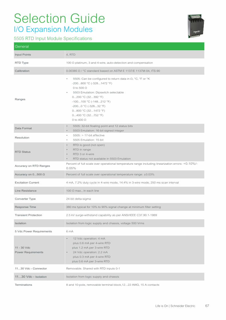
Selection GuideI/O Expansion Modules5505 RTD Input Module Specifications
General
Input Points 4, RTD
RTD Type 100 Ω platinum, 3 and 4-wire, auto-detection and compensation
Calibration 0.00385 Ω / °C standard based on ASTM E 1137/E 1137M-04, ITS-90
Ranges
• 5505: Can be configured to return data in Ω, °C, °F or °K
-200...800 °C (-328...1472 °F)
0 to 500 Ω
• 5503 Emulation: Dipswitch selectable
0...200 °C (32...392 °F)
-100...100 °C (-148...212 °F)
-200...0 °C (-328...32 °F)
0...800 °C (32...1472 °F)
0...400 °C (32...752 °F)
0 to 400 Ω
Data Format• 5505: 32-bit floating point and 12 status bits
• 5503 Emulation: 16-bit signed integer
Resolution• 5505: > 17-bit effective
• 5505 Emulation: 15-bit
RTD Status
• RTD is good (not open)
• RTD in range
• RTD 3 or 4-wire
• RTD status not available in 5503 Emulation
Accuracy on RTD RangesPercent of full scale over operational temperature range including linearization errors: +0.10%/-
0.05%
Accuracy on 0...500 Ω Percent of full scale over operational temperature range: ±0.03%
Excitation Current 4 mA, 7.2% duty cycle in 4-wire mode, 14.4% in 3-wire mode, 250 ms scan interval
Line Resistance 100 Ω max., in each line
Converter Type 24-bit delta-sigma
Response Time 380 ms typical for 10% to 90% signal change at minimum filter setting
Transient Protection 2.5 kV surge-withstand capability as per ANSI/IEEE C37.90.1-1989
Isolation Isolation from logic supply and chassis, voltage 500 Vrms
5 Vdc Power Requirements 6 mA
11 - 30 Vdc
Power Requirements
• 12 Vdc operation: 4 mA
plus 0.6 mA per 4-wire RTD
plus 1.2 mA per 3-wire RTD
• 24 Vdc operation: 2.2 mA
plus 0.3 mA per 4-wire RTD
plus 0.6 mA per 3-wire RTD
11...30 Vdc - Connector Removable. Shared with RTD inputs 0-1
11...30 Vdc - Isolation Isolation from logic supply and chassis
Terminations 8 and 10-pole, removable terminal block,12...22 AWG, 15 A contacts
Life is On | Schneider Electric 67
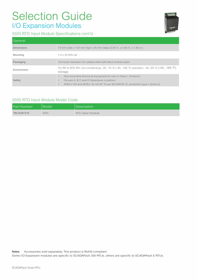
Selection GuideI/O Expansion Modules
5505 RTD Input Module Model Code
Part Number Model Description
TBUX297318 5505 RTD input module
Notes: Accessories sold separately. This product is RoHS-compliant.
Some I/O Expansion modules are specific to SCADAPack 300 RTUs, others are specific to SCADAPack E RTUs.
5505 RTD Input Module Specifications cont'd
General
Dimensions 74 mm wide x 124 mm high x 45 mm deep (2.90 in. x 4.90 in. x 1.80 in.)
Mounting 7.5 x 35 DIN rail
Packaging Corrosion resistant zinc plated steel with black enamel paint
Environment5% RH to 95% RH, non-condensing, -40...70 °C (-40...158 °F) operation, -40...85 °C (-40...185 °F)
storage
Safety
• Non-Incendive Electrical Equipment for Use in Class I, Division2
• Groups A, B C and D Hazardous Locations
• ATEX II 3G and IECEx: Ex nA IIC T4 per EN 60079-15, protection type n (Zone 2)
SCADAPack Smart RTU
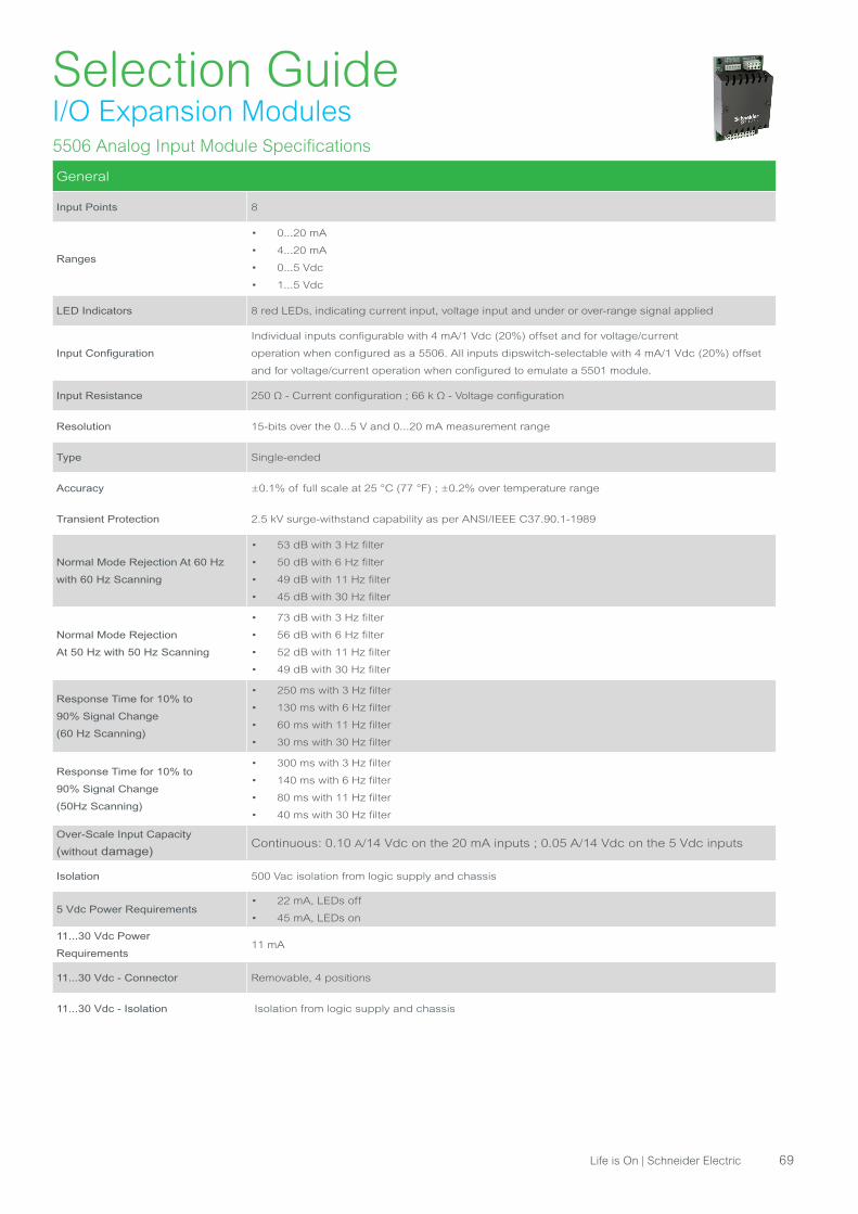
Selection GuideI/O Expansion Modules5506 Analog Input Module Specifications
General
Input Points 8
Ranges
• 0...20 mA
• 4...20 mA
• 0...5 Vdc
• 1...5 Vdc
LED Indicators 8 red LEDs, indicating current input, voltage input and under or over-range signal applied
Input Configuration
Individual inputs configurable with 4 mA/1 Vdc (20%) offset and for voltage/current
operation when configured as a 5506. All inputs dipswitch-selectable with 4 mA/1 Vdc (20%) offset
and for voltage/current operation when configured to emulate a 5501 module.
Input Resistance 250 Ω - Current configuration ; 66 k Ω - Voltage configuration
Resolution 15-bits over the 0...5 V and 0...20 mA measurement range
Type Single-ended
Accuracy ±0.1% of full scale at 25 °C (77 °F) ; ±0.2% over temperature range
Transient Protection 2.5 kV surge-withstand capability as per ANSI/IEEE C37.90.1-1989
Normal Mode Rejection At 60 Hz
with 60 Hz Scanning
• 53 dB with 3 Hz filter
• 50 dB with 6 Hz filter
• 49 dB with 11 Hz filter
• 45 dB with 30 Hz filter
Normal Mode Rejection
At 50 Hz with 50 Hz Scanning
• 73 dB with 3 Hz filter
• 56 dB with 6 Hz filter
• 52 dB with 11 Hz filter
• 49 dB with 30 Hz filter
Response Time for 10% to
90% Signal Change
(60 Hz Scanning)
• 250 ms with 3 Hz filter
• 130 ms with 6 Hz filter
• 60 ms with 11 Hz filter
• 30 ms with 30 Hz filter
Response Time for 10% to
90% Signal Change
(50Hz Scanning)
• 300 ms with 3 Hz filter
• 140 ms with 6 Hz filter
• 80 ms with 11 Hz filter
• 40 ms with 30 Hz filter
Over-Scale Input Capacity
(without damage) Continuous: 0.10 A/14 Vdc on the 20 mA inputs ; 0.05 A/14 Vdc on the 5 Vdc inputs
Isolation 500 Vac isolation from logic supply and chassis
5 Vdc Power Requirements • 22 mA, LEDs off
• 45 mA, LEDs on
11...30 Vdc Power
Requirements11 mA
11...30 Vdc - Connector Removable, 4 positions
11...30 Vdc - Isolation Isolation from logic supply and chassis
Life is On | Schneider Electric 69
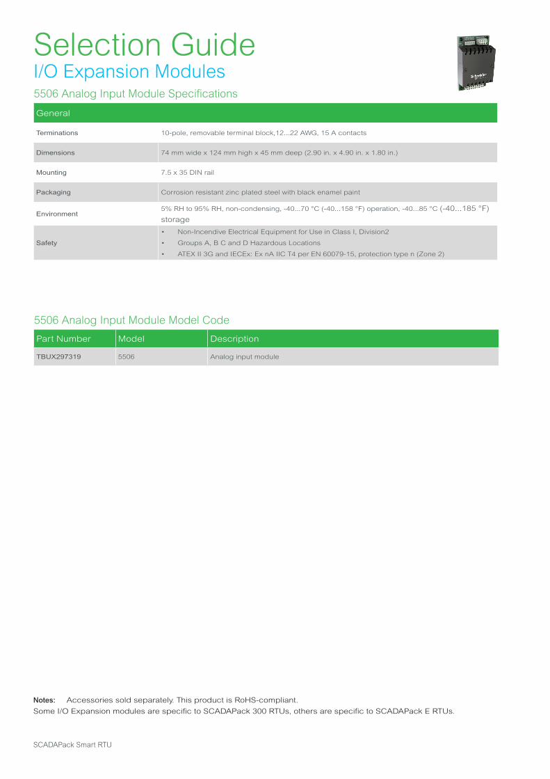
5506 Analog Input Module Specifications
General
Terminations 10-pole, removable terminal block,12...22 AWG, 15 A contacts
Dimensions 74 mm wide x 124 mm high x 45 mm deep (2.90 in. x 4.90 in. x 1.80 in.)
Mounting 7.5 x 35 DIN rail
Packaging Corrosion resistant zinc plated steel with black enamel paint
Environment5% RH to 95% RH, non-condensing, -40...70 °C (-40...158 °F) operation, -40...85 °C (-40...185 °F)
storage
Safety
• Non-Incendive Electrical Equipment for Use in Class I, Division2
• Groups A, B C and D Hazardous Locations
• ATEX II 3G and IECEx: Ex nA IIC T4 per EN 60079-15, protection type n (Zone 2)
5506 Analog Input Module Model Code
Part Number Model Description
TBUX297319 5506 Analog input module
Notes: Accessories sold separately. This product is RoHS-compliant.
Some I/O Expansion modules are specific to SCADAPack 300 RTUs, others are specific to SCADAPack E RTUs.
Selection GuideI/O Expansion Modules
SCADAPack Smart RTU

5606 | 5607 Analog/Digital I/O Modules Specifications
Digital and Analog Inputs/Outputs
I/O Module 5606 5607
Analog Inputs 8 8
Analog Outputs 2 (option) 2 (option)
Digital Inputs 32 16
Digital Outputs 16 10
I/O
Analog Inputs
Software configurable to 0...20 mA, 4...20 mA, 0...5 Vdc or 0...10 Vdc
• Resolution: 15-bit ADC (15-bit over the measurement range in 10 Vdc, 14-bit in
20 mA)
• Accuracy: ±0.1% of full scale at 25 °C (77 °F), ±0.2% over temperature range
• Input Resistance: 250 Ω or 20 kΩ in 20 mA or 10 Vdc configurations
• Isolation: 500 Vac from logic and chassis
• Normal rejection mode: 27 dB at 60 Hz
Analog Outputs
0...20 mA, 4...20 mA, voltage output may be accomplished with external precision
resistor
• Resolution: 12-bit over 0...20 mA range
• Accuracy: ±0.15% at 25 °C (77 °F), ±0.35% of full scale over temperature range
• Response Time: less than 10 μs for 10% to 90% signal change
• Power Supply: 12…30 Vdc, external
• Power (Current) Requirements: 10 mA plus up to 20 mA per output
• Isolation: isolated from RTU logic and chassis
• Load Range: 12 Vdc: 0…375 Ω, 24 Vdc: 0…925 Ω,
• Logic End-Of- Scan to Signal Update Latency: typically 18... 27 ms
Digital Inputs
12…24 Vdc
• Turn on voltage: 9 Vdc (minimum), Turn off voltage: 4 Vdc (maximum)
• Over-voltage tolerance: 150% sustained over-voltage without foreseeable
damage
• DC input current: 0.67 mA at 24 Vdc
• Isolation : in group of 8, 1500 Vac from logic supply and chassis
Digital Outputs
Relays (Form A)
• 4 contacts share one common
• Isolation : isolated in groups of 4. Isolated from RTU logic, RTU chassis and
other groups to 1500 Vac
• Maximum Switching Voltage: 30 Vdc
• Maximum Switching Load: 150 W or 1250 VA (5 A)
General
Power Supply
• Analog Inputs & Outputs: 12 mA at 12…30 Vdc, plus analog output
requirements
• Digital Inputs & Outputs: 650 mA at 5 Vdc, fully loaded
I/O Terminations
• 5606: 5, 9, 10-pole connectors, 0.0810...3.31mm2 (28...12 AWG), solid or
stranded.
• 5607: 5, 9, 12-pole connectors, 0.0810...3.31mm2 (28...12 AWG), solid or
stranded
Selection GuideI/O Expansion Modules
Life is On | Schneider Electric 71
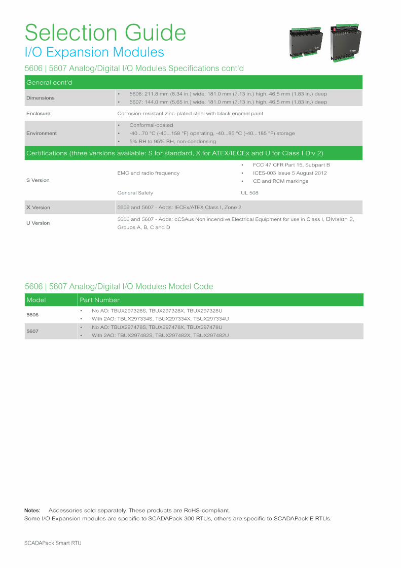
5606 | 5607 Analog/Digital I/O Modules Specifications cont'd
General cont'd
Dimensions• 5606: 211.8 mm (8.34 in.) wide, 181.0 mm (7.13 in.) high, 46.5 mm (1.83 in.) deep
• 5607: 144.0 mm (5.65 in.) wide, 181.0 mm (7.13 in.) high, 46.5 mm (1.83 in.) deep
Enclosure Corrosion-resistant zinc-plated steel with black enamel paint
Environment
• Conformal-coated
• -40...70 °C (-40...158 °F) operating, -40...85 °C (-40...185 °F) storage
• 5% RH to 95% RH, non-condensing
Certifications (three versions available: S for standard, X for ATEX/IECEx and U for Class I Div 2)
S Version
EMC and radio frequency
• FCC 47 CFR Part 15, Subpart B
• ICES-003 Issue 5 August 2012
• CE and RCM markings
General Safety UL 508
X Version 5606 and 5607 - Adds: IECEx/ATEX Class I, Zone 2
U Version5606 and 5607 - Adds: cCSAus Non incendive Electrical Equipment for use in Class I, Division 2,
Groups A, B, C and D
Selection GuideI/O Expansion Modules
5606 | 5607 Analog/Digital I/O Modules Model Code
Model Part Number
5606• No AO: TBUX297328S, TBUX297328X, TBUX297328U
• With 2AO: TBUX297334S, TBUX297334X, TBUX297334U
5607• No AO: TBUX297478S, TBUX297478X, TBUX297478U
• With 2AO: TBUX297482S, TBUX297482X, TBUX297482U
Notes: Accessories sold separately. These products are RoHS-compliant.
Some I/O Expansion modules are specific to SCADAPack 300 RTUs, others are specific to SCADAPack E RTUs.
SCADAPack Smart RTU

6601 Combination IO Module for SCADAPack x70 RTU Specifications
IO
Digital Inputs
16:
Typical Operating Voltage: 12...24 Vdc
Turn-on Voltage Minimum: 9 Vdc
Turn-off Voltage Maximum: 4 Vdc
Over-voltage Tolerance: 36 Vdc sustained over-voltage without foreseeable damage
Input Current
• 0.9…1.2 mA at 12 Vdc
• 2.1…2.4 mA at 24 Vdc
Timestamping: 1 ms Sequence of Event (SOE)
Isolation:
• Isolation is in 2 groups of 8
• Isolation from device logic and chassis
• 1000 Vac or 1500 Vdc
Counter Inputs
8
Electrical Characteristics: Shared with digital input channels
Reporting:
• 16-bit and 32-bit counters
• Deviation
• Timestamped events
• Polled, unsolicited reporting
Frequency: Up to 8 channels:
• DI 1 to 4: 0...1.5 kHz
• DI 5 to 8: 0...150 Hz
Digital Outputs
8
Type:
• 2 Form C single-pole double-throw (SPDT) relays available to the application
• Separate Normally Open/Normally Closed/Common
• 6 Form A relays available to the application
• Normally Open, one Common
Isolation: 500 Vac minimum to device logic
Maximum Switching Voltage: 30 Vdc or 25 Vac
Maximum Switching Load:
• 60 W or 50 VA per relay
• 2 A per relay
• 2 A per common on digital outputs 1-2
• 12 A per common on digital outputs 3-8
Status and reporting:
• Individual relay pole feedback to software
• Output state poll
Temperature de-rating:
Mounted horizontally on a vertical surface: 2 A maximum per relay at 60 °C (140 °F), de-rate by 0.1
A per 1 °C to 1 A maximum per relay at a maximum ambient temperature of 70 °C (158 °F)
Mounted in any other position: 2 A maximum per relay at 60 °C (140 °F), de-rate by 0.1 A per 1 °C to
1.5 A maximum per relay at a maximum ambient temperature of 65 °C (149 °F)
Controls:
• Direct Operate
• Select Before Operate
• Trip/Close
• Latch
• Pulse
Selection GuideCommunication Modules
Life is On | Schneider Electric 73

6601 Combination IO Module for SCADAPack x70 RTU Specifications
IO
Analog Inputs
6
Type: Uni-polar, differential, voltage or current
Resolution (filtered):
• 24-bit conversion yields an effective 19 bits of resolution during filtered conversions
• 10 μV on the 5 Vdc range
• 40 nA resolution on the 20 mA range
Resolution (fast):
• 24-bit conversion yields an effective 13 bits of resolution during unfiltered conversions.
• 0.6 mV resolution on the 5 Vdc range
• 2.4 μA resolution on the 20 mA range
Accuracy:
• ±0.1% of full scale at 25 ºC (77 ºF)
• ±0.2% over-temperature range
Isolation: 250 Vac isolation between channels and from device logic and chassis
Input resistance:
• 250 Ω in current configurations
• 800 kΩ in voltage configurations
Ranges:
• Input Type: 4...20 mA, 0...20 mA, 1...5 Vdc, or 0...5 Vdc
• Under-range: 4...20 mA measures to 0 mA
• Individual inputs can be configured for current or voltage operation using DIP switches.
• Calibration in voltage mode 1...5 Vdc is available as an option.
Sampling Rate:
• Filtered: 500 ms per 6 channels
• Fast: 30 ms per 6 channels
Common Mode Rejection: 80 dB
Normal Mode Rejection:
• Filtered: 86 dB (50/60 Hz)
• Fast: Not applicable
Reporting:
• Deviation
• 8 alert limits
• Under- and over-range events
• Quality flags
• Integer/floating point
• Timestamped events
• Polled, unsolicited reporting on deviation and per alert limit
Timestamping: 30 ms Sequence of Event (SOE)
I/O Cable Length: 30 m (98.4 ft) Maximum
Selection GuideCommunication Modules
SCADAPack Smart RTU
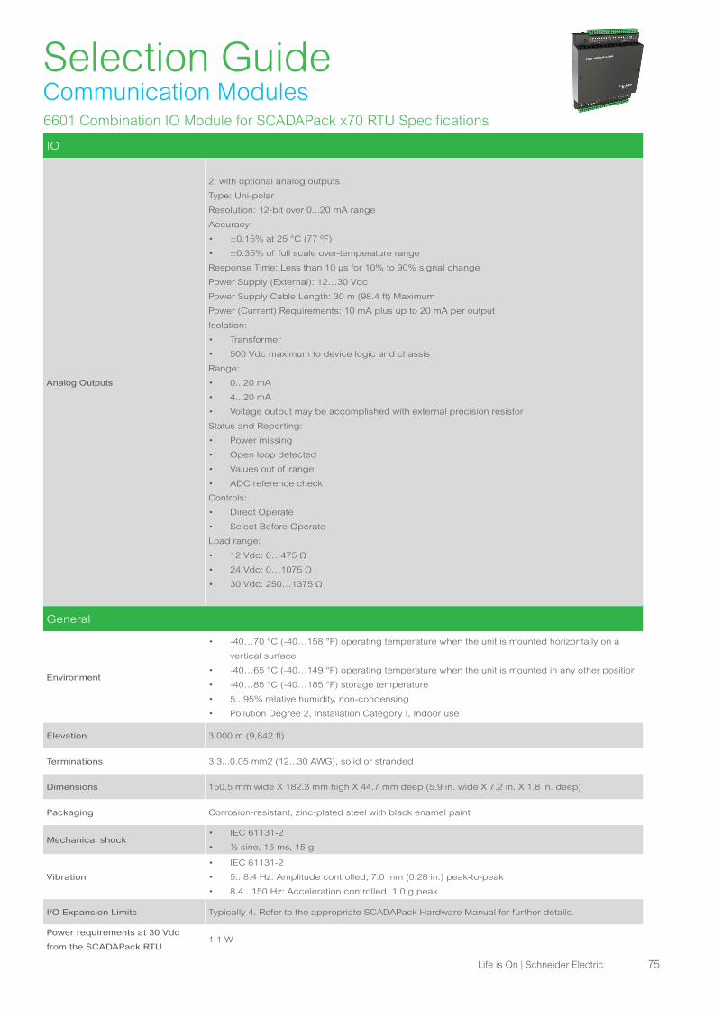
6601 Combination IO Module for SCADAPack x70 RTU Specifications
IO
Analog Outputs
2: with optional analog outputs
Type: Uni-polar
Resolution: 12-bit over 0...20 mA range
Accuracy:
• ±0.15% at 25 °C (77 ºF)
• ±0.35% of full scale over-temperature range
Response Time: Less than 10 μs for 10% to 90% signal change
Power Supply (External): 12…30 Vdc
Power Supply Cable Length: 30 m (98.4 ft) Maximum
Power (Current) Requirements: 10 mA plus up to 20 mA per output
Isolation:
• Transformer
• 500 Vdc maximum to device logic and chassis
Range:
• 0...20 mA
• 4...20 mA
• Voltage output may be accomplished with external precision resistor
Status and Reporting:
• Power missing
• Open loop detected
• Values out of range
• ADC reference check
Controls:
• Direct Operate
• Select Before Operate
Load range:
• 12 Vdc: 0…475 Ω
• 24 Vdc: 0…1075 Ω
• 30 Vdc: 250…1375 Ω
Selection GuideCommunication Modules
Life is On | Schneider Electric 75
General
Environment
• -40…70 °C (-40…158 °F) operating temperature when the unit is mounted horizontally on a
vertical surface
• -40…65 °C (-40…149 °F) operating temperature when the unit is mounted in any other position
• -40…85 °C (-40…185 °F) storage temperature
• 5...95% relative humidity, non-condensing
• Pollution Degree 2, Installation Category I, Indoor use
Elevation 3,000 m (9,842 ft)
Terminations 3.3...0.05 mm2 (12...30 AWG), solid or stranded
Dimensions 150.5 mm wide X 182.3 mm high X 44.7 mm deep (5.9 in. wide X 7.2 in. X 1.8 in. deep)
Packaging Corrosion-resistant, zinc-plated steel with black enamel paint
Mechanical shock• IEC 61131-2
• ½ sine, 15 ms, 15 g
Vibration
• IEC 61131-2
• 5...8.4 Hz: Amplitude controlled, 7.0 mm (0.28 in.) peak-to-peak
• 8.4...150 Hz: Acceleration controlled, 1.0 g peak
I/O Expansion Limits Typically 4. Refer to the appropriate SCADAPack Hardware Manual for further details.
Power requirements at 30 Vdc
from the SCADAPack RTU1.1 W
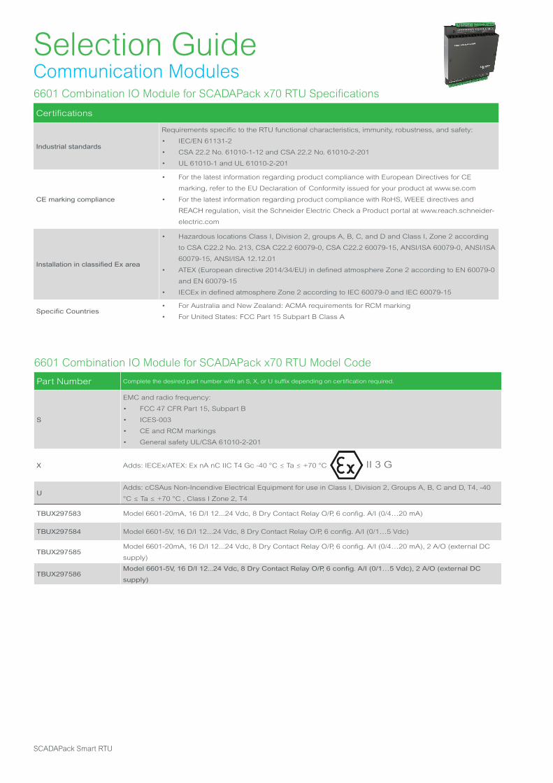
6601 Combination IO Module for SCADAPack x70 RTU Model Code
Part Number Complete the desired part number with an S, X, or U suffix depending on certification required.
S
EMC and radio frequency:
• FCC 47 CFR Part 15, Subpart B
• ICES-003
• CE and RCM markings
• General safety UL/CSA 61010-2-201
X Adds: IECEx/ATEX: Ex nA nC IIC T4 Gc -40 °C ≤ Ta ≤ +70 °C II 3 G
UAdds: cCSAus Non-Incendive Electrical Equipment for use in Class I, Division 2, Groups A, B, C and D, T4, -40
°C ≤ Ta ≤ +70 °C , Class I Zone 2, T4
TBUX297583 Model 6601-20mA, 16 D/I 12...24 Vdc, 8 Dry Contact Relay O/P, 6 config. A/I (0/4…20 mA)
TBUX297584 Model 6601-5V, 16 D/I 12...24 Vdc, 8 Dry Contact Relay O/P, 6 config. A/I (0/1…5 Vdc)
TBUX297585Model 6601-20mA, 16 D/I 12...24 Vdc, 8 Dry Contact Relay O/P, 6 config. A/I (0/4…20 mA), 2 A/O (external DC
supply)
TBUX297586Model 6601-5V, 16 D/I 12...24 Vdc, 8 Dry Contact Relay O/P, 6 config. A/I (0/1…5 Vdc), 2 A/O (external DC
supply)
Selection GuideCommunication Modules6601 Combination IO Module for SCADAPack x70 RTU Specifications
Certifications
Industrial standards
Requirements specific to the RTU functional characteristics, immunity, robustness, and safety:
• IEC/EN 61131-2
• CSA 22.2 No. 61010-1-12 and CSA 22.2 No. 61010-2-201
• UL 61010-1 and UL 61010-2-201
CE marking compliance
• For the latest information regarding product compliance with European Directives for CE
marking, refer to the EU Declaration of Conformity issued for your product at www.se.com
• For the latest information regarding product compliance with RoHS, WEEE directives and
REACH regulation, visit the Schneider Electric Check a Product portal at www.reach.schneider-
electric.com
Installation in classified Ex area
• Hazardous locations Class I, Division 2, groups A, B, C, and D and Class I, Zone 2 according
to CSA C22.2 No. 213, CSA C22.2 60079-0, CSA C22.2 60079-15, ANSI/ISA 60079-0, ANSI/ISA
60079-15, ANSI/ISA 12.12.01
• ATEX (European directive 2014/34/EU) in defined atmosphere Zone 2 according to EN 60079-0
and EN 60079-15
• IECEx in defined atmosphere Zone 2 according to IEC 60079-0 and IEC 60079-15
Specific Countries• For Australia and New Zealand: ACMA requirements for RCM marking
• For United States: FCC Part 15 Subpart B Class A
SCADAPack Smart RTU
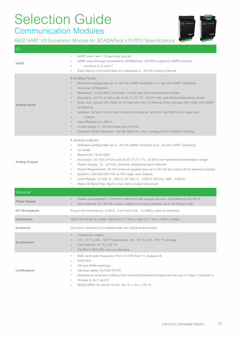
6602 HART I/O Expansion Module for SCADAPack x70 RTU Specifications
IO
HART
• HART scan rate <10 seconds typical1
• HART pass-through provided by SCADAPack x70 RTU supports HART protocol
• revisions 5, 6, and 7
• Each device communicates on a separate 4...20 mA analog channel
Analog Inputs
8 analog inputs:
• Software-configurable as 4...20 mA (HART enabled) or 0...20 mA (HART disabled)
• Uni-polar, differential
• Resolution: 24-bit ADC (effective: 14-bits over the measurement range)
• Accuracy: ±0.1% of full scale at 25 °C (77 °F), ±0.2% over operating temperature range
• Scan rate: typical 270 mSec for 8 channels with no filtering (Fast setting), 800 mSec with 50/60
Hz filtering
• Isolation: 50 Vac/70 Vdc from channel to channel, and 250 Vac/350 Vdc to logic and
• chassis
• Input Resistance: 280 Ω
• Under-range: 4...20 mA measures to 0 mA
• Common Mode Rejection: -80 dB (@60 Hz. when configured for 50/60Hz filtering)
Analog Outputs
4 analog outputs:
• Software-configurable as 4...20 mA (HART enabled) or 0...20 mA (HART disabled)
• Uni-polar
• Resolution: 16-bit DAC
• Accuracy: ±0.15% of full scale at 25 ˚C (77 ˚F), ±0.35% over operating temperature range
• Power Supply: 12…30 Vdc, external, shared by each channel
• Power Requirement: 20 mA (internal supply) plus up to 20 mA per output (from external supply)
• Isolation: 250 Vac/350 Vdc to RTU logic and chassis
• Load Range: 12 Vdc: 0…450 Ω, 24 Vdc: 0…1050 Ω, 30 Vdc: 250…1350 Ω
• Status & Reporting: Open Loop status, output value poll
General
Power Supply• Power consumption 1.3 W from internal 5 Vdc supply (source: SCADAPack x70 RTU)
• One external 12...30 Vdc power supply for analog outputs, up to 20 mA per loop.
I/O Terminations Plug-in terminal blocks, 0.0810...3.31 mm2 (28...12 AWG), solid or stranded
Dimensions 102.0 mm (4.02 in.) wide, 182.4 mm (7.18 in.) high, 47.1 mm (1.85 in.) deep
Enclosure Corrosion resistant zinc-plated steel with black enamel paint
Environment
• Conformal coated
• -40...70 °C (-40...158 °F) operating, -40...85 °C (-40...185 °F) storage
• Cold start at -40 °C (-40 °F)
• 5% RH to 95% RH, non-condensing
Certifications
• EMC and radio frequency FCC 47 CFR Part 15, Subpart B
• ICES-003
• CE and RCM markings
• General safety UL/CSA 61010
• Hazardous locations cCSAus Non-Incendive Electrical Equipment for use in Class I, Division 2,
• Groups A, B, C and D
• IECEx/ATEX: Ex nA IIC T4 Gc -40 °C ≤ Ta ≤ +70 °C
Selection GuideCommunication Modules
Life is On | Schneider Electric 77
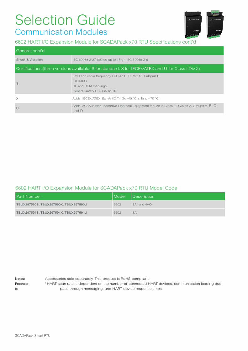
Notes: Accessories sold separately. This product is RoHS-compliant.
Footnote: 1 HART scan rate is dependent on the number of connected HART devices, communication loading due
to pass-through messaging, and HART device response times.
6602 HART I/O Expansion Module for SCADAPack x70 RTU Model Code
Part Number Model Description
TBUX297590S, TBUX297590X, TBUX297590U 6602 8AI and 4AO
TBUX297591S, TBUX297591X, TBUX297591U 6602 8AI
Selection GuideCommunication Modules6602 HART I/O Expansion Module for SCADAPack x70 RTU Specifications cont'd
General cont'd
Shock & Vibration IEC 60068-2-27 (tested up to 15 g), IEC 60068-2-6
Certifications (three versions available: S for standard, X for IECEx/ATEX and U for Class I Div 2)
S
EMC and radio frequency FCC 47 CFR Part 15, Subpart B
ICES-003
CE and RCM markings
General safety UL/CSA 61010
X Adds: IECEx/ATEX: Ex nA IIC T4 Gc -40 °C ≤ Ta ≤ +70 °C
UAdds: cCSAus Non-Incendive Electrical Equipment for use in Class I, Division 2, Groups A, B, C
and D
SCADAPack Smart RTU

6607 Combination IO Module for SCADAPack x70 RTU Specifications
IO
Digital Inputs
16:
Voltage: 12 Vdc or 24 Vdc (Typical)
Over-voltage tolerance:
• 36 Vdc
• 150% sustained over-voltage without foreseeable damage
Input current:
• 1.2 mA typical at 12 Vdc
• 2.4 mA typical at 24 Vdc
Input logic-HI level: OFF to ON transition threshold is typically 6.5 Vdc
Timestamping: 10 ms Sequence of Event (SOE)
Status: Chatter filter detection when digital state changes faster than 5 Hz
Isolation:
• Isolation is in 2 groups of 8
• Isolation from logic supply and chassis: 250 Vac/350 Vdc
Counter Inputs
8:
Electrical characteristics: Shared with digital input channels
Reporting:
• 32-bit counters
• Deviation
• Timestamped events
• Unsolicited reporting
DI1, DI2, DI3, and DI4-supported counting:
• Range: 0 to 1.5 kHz
• Rising edge counting
• Falling edge counting (using digital input state inversion)
DI5, DI6, DI7, and DI8-supported counting:
• Range: 0 to 500 Hz
• Rising edge counting
• Falling edge counting (using digital input state inversion)
Digital Outputs
10:
Type:
• Form A Contacts (normally open)
• 5 contacts share one common
Inductive loads:
• To suppress the noise in AC and DC circuits and help extend the life of the relay
contacts, place a metal oxide varistor (for AC circuits) or a diode (for DC circuits)
across the coil. See Digital Output Wiring Example for further information
Isolation:
• Isolation is in 2 groups of 5
• 250 VAC / 350 VDC maximum to SCADAPack logic and chassis
Dry Contact Relay Version
Contact rating:
• 2 A, 30 VDC
• 10 A maximum per common
Selection GuideCommunication Modules
Life is On | Schneider Electric 79
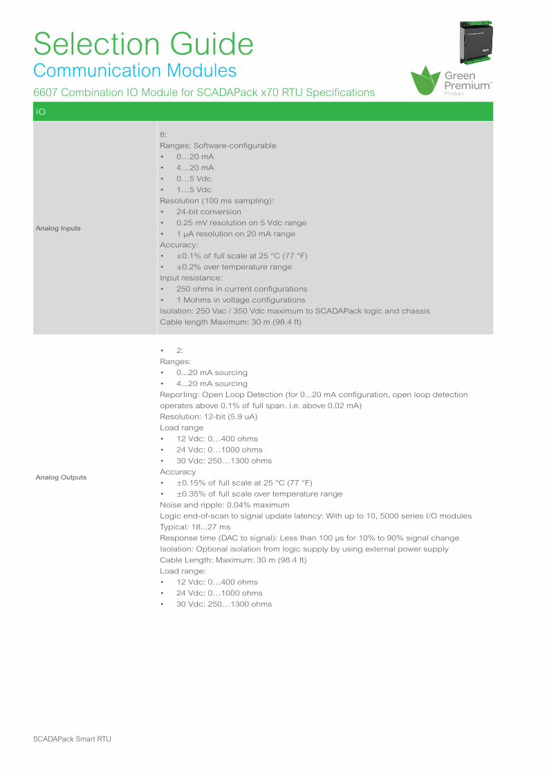
6607 Combination IO Module for SCADAPack x70 RTU Specifications
IO
Analog Inputs
8:
Ranges: Software-configurable
• 0…20 mA
• 4…20 mA
• 0…5 Vdc
• 1…5 Vdc
Resolution (100 ms sampling):
• 24-bit conversion
• 0.25 mV resolution on 5 Vdc range
• 1 μA resolution on 20 mA range
Accuracy:
• ±0.1% of full scale at 25 °C (77 °F)
• ±0.2% over temperature range
Input resistance:
• 250 ohms in current configurations
• 1 Mohms in voltage configurations
Isolation: 250 Vac / 350 Vdc maximum to SCADAPack logic and chassis
Cable length Maximum: 30 m (98.4 ft)
Analog Outputs
• 2:
Ranges:
• 0...20 mA sourcing
• 4...20 mA sourcing
Reporting: Open Loop Detection (for 0...20 mA configuration, open loop detection
operates above 0.1% of full span. i.e. above 0.02 mA)
Resolution: 12-bit (5.9 uA)
Load range
• 12 Vdc: 0…400 ohms
• 24 Vdc: 0…1000 ohms
• 30 Vdc: 250…1300 ohms
Accuracy
• ±0.15% of full scale at 25 °C (77 °F)
• ±0.35% of full scale over temperature range
Noise and ripple: 0.04% maximum
Logic end-of-scan to signal update latency: With up to 10, 5000 series I/O modules
Typical: 18...27 ms
Response time (DAC to signal): Less than 100 μs for 10% to 90% signal change
Isolation: Optional isolation from logic supply by using external power supply
Cable Length: Maximum: 30 m (98.4 ft)
Load range:
• 12 Vdc: 0…400 ohms
• 24 Vdc: 0…1000 ohms
• 30 Vdc: 250…1300 ohms
Selection GuideCommunication Modules
SCADAPack Smart RTU

6607 Combination IO Module for SCADAPack x70 RTU Model Code
Part Number Model Description
TBUX297592S 6607 16, DI, 8 CI, 10 DO, 8 AI, 2 AO
Selection GuideCommunication Modules6607 Combination IO Module for SCADAPack x70 RTU Specifications
General
Environment
• -40…70 °C (-40…158 °F) operating temperature when the unit is mounted horizontally on a
vertical surface
• -40…65 °C (-40…149 °F) operating temperature when the unit is mounted in any other position
• -40…85 °C (-40…185 °F) storage temperature
• 5...95% relative humidity, non-condensing
• Pollution Degree 2, Installation Category I, Indoor use
Elevation 3,000 m (9,842 ft)
Terminations 3.3...0.05 mm2 (12...30 AWG), solid or stranded
Dimensions
• 142 mm (5.6 in) wide
• 166 mm (6.5 in) high
• 46 mm (1.8 in) deep
Packaging Corrosion-resistant, zinc-plated steel with black enamel paint
Mechanical shock• IEC 61131-2
• ½ sine, 15 ms, 15 g
Vibration:
IEC 61131-2
• 5...8.4 Hz: Amplitude-controlled, 7.0 mm (0.28 in) peak-to-peak
• 8.4...150 Hz: Acceleration controlled, 1.0 g peak
Power Supply Input Voltage::
• Rated Voltage 14…29 Vdc
• Turn-on 10…11.5 Vdc
• Turn-off 9…10 Vdc
Power requirements from the
SCADAPack1.2 W
Certifications
Industrial standards
Requirements specific to the SCADAPack functional characteristics, immunity, robustness, and
safety:
• IEC/EN 61131-2
• CSA 22.2 No. 61010-1-12 and CSA 22.2 No. 61010-2-201
• UL 61010-1 and UL 61010-2-201
CE marking compliance
• For the latest information regarding product compliance with European Directives for CE
marking, refer to the EU Declaration of Conformity issued for your product at se.com
• For the latest information regarding product compliance with RoHS, WEEE directives and
REACH regulation, visit the Schneider Electric Check a Product portal at https://www.reach.
schneider-electric.com
Installation in classified Ex areaHazardous locations Class I, Division 2, groups A, B, C, and D, T4 and Class I, Zone 2, IIC
according to CSA C22.2 No. 213-17 and ANSI/ISA 12.12.01
Specific countries• For Australia and New Zealand: ACMA requirements for RCM marking
• For United States: FCC Part 15 Subpart B Class A
Life is On | Schneider Electric 81

5904 HART Interface Module Specifications
General
Modulation
• Bell 202 Frequency Shift Key (FSK)
• Mark = 1200 Hz
• Space = 2200 Hz
Data Rate 1200 baud
Transmit Level 500 mVp-p into 250 Ω
Receive Sensitivity• 120 mVp-p guaranteed on
• 80 mVp-p guaranteed off
Output Impedance• 300 Ω
• Transformer-isolated
Input Impedance• 4000 Ω
• Transformer-isolated
Load Resistor 250 Ω, 1 Watt maximum
Visual Indicators• TX: Transmitted data LED
• RX: Received data LED
Power Requirements 5 Vdc @ 20 mA
Terminations 4-pole, removable terminal block, 12...22 AWG, 15 A contacts
Dimensions 108 mm W. x 118 mm H. x 44 mm D. (4.25 in. x 4.625 in. x 1.75 in.)
Mounting 7.5 x 35 DIN rail
Packaging Corrosion-resistant zinc-plated steel with black enamel paint
Environment 5% RH to 95% RH, non-condensing; -40...70 °C (-40...158 °F)
Safety cCSAus and cULus Class I, Division 2 Hazardous Area Rating, UL508 listed
Selection GuideCommunication Modules
Notes: Accessories sold separately. This product is not RoHS-compliant.
5904 HART Interface Module Model Code
Part Number Model Description
TBUX297205 5904 HART interface module
SCADAPack Smart RTU

Schneider Electric Systems USA
Process Automation, SCADA & Telemetry38 Neponset Avenue, Foxboro, Massachusetts 02035 USADirect Worldwide: +1 (613) 591-1943Email: [email protected] Free within North America: +1 (888) 267-2232www.se.com
© 2019 Schneider Electric. All Rights Reserved. Schneider Electric, Life is On Schneider Electric, Green Premium, Modbus, Realflo, RemoteConnect, SCADAPack, Telepace, and Trio are trademarks and the property of Schneider Electric SE, its subsidiaries and affiliated companies. All other trademarks are the property of their respective owners. May 2021• TBUL00001-03
Disclaimer: Schneider Electric reserves the right to alter product pricing and product specifications.For more information, visit www.se.com.
se.com
MA SELMON Company4 Oxford Road Milford, CT 06460Brad [email protected](203)377-3525
Related Documents