COMP 421 /CMPET 401 COMP 421 /CMPET 401 COMMUNICATIONS and NETWORKING CLASS 6

COMP 421 /CMPET 401 COMMUNICATIONS and NETWORKING CLASS 6.
Dec 13, 2015
Welcome message from author
This document is posted to help you gain knowledge. Please leave a comment to let me know what you think about it! Share it to your friends and learn new things together.
Transcript
COMP 421 /CMPET 401COMP 421 /CMPET 401
COMMUNICATIONS and NETWORKING
CLASS 6

Encoding TechniquesEncoding Techniques
Digital data, digital signal – Easy encoding / Less Complex Less Expensive
Analog data, digital signal– Can transmit data over Digital Network
Digital data, analog signal– Modems / Fiber / Unguided Media
Analog data, analog signal– Cheap & Easy Baseband Transmission / FDM
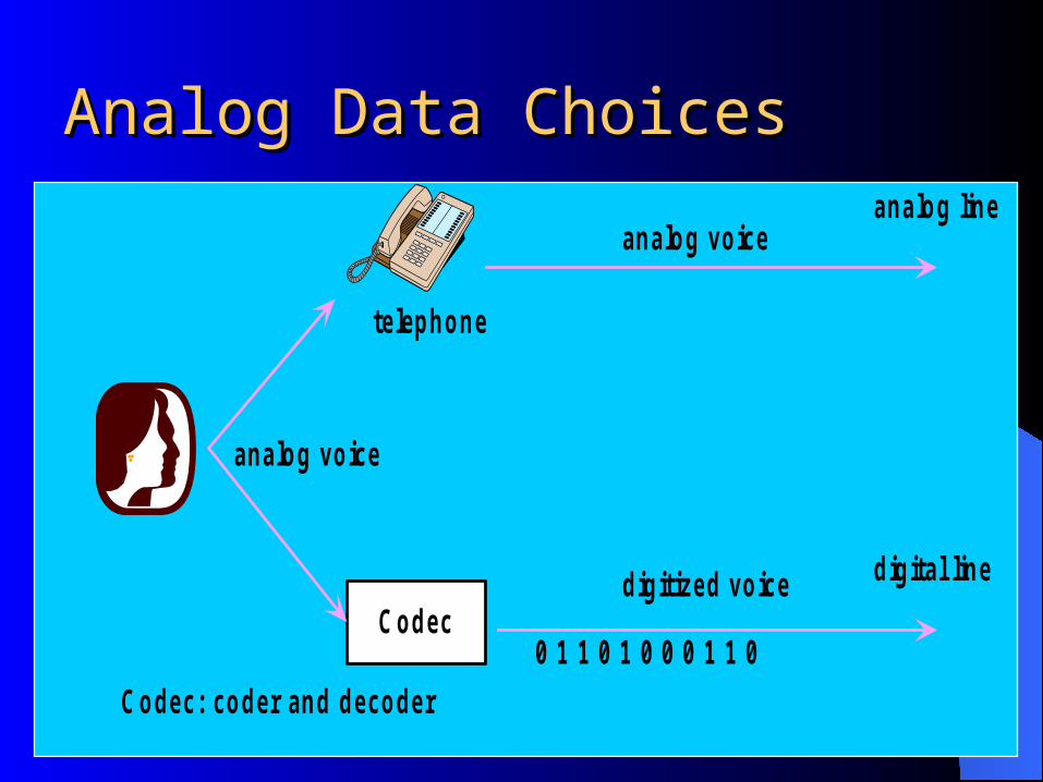
Codec
Codec: coder and decoder
telephone
analog voice
analog line
digital line
analog voice
0 1 1 0 1 0 0 0 1 1 0
digitized voice
Analog Data ChoicesAnalog Data Choices

DSU
DSU: data service unit
analog line
digital line
moduated data
0 1 1 0 1 0 0 0 1 1 0
data
data
modem
Digital Data ChoicesDigital Data Choices
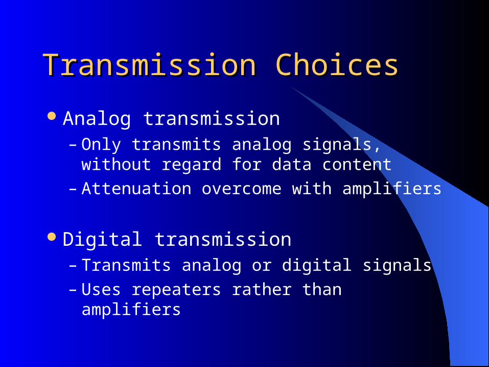
Transmission ChoicesTransmission Choices
Analog transmission– Only transmits analog signals, without regard
for data content– Attenuation overcome with amplifiers
Digital transmission– Transmits analog or digital signals– Uses repeaters rather than amplifiers
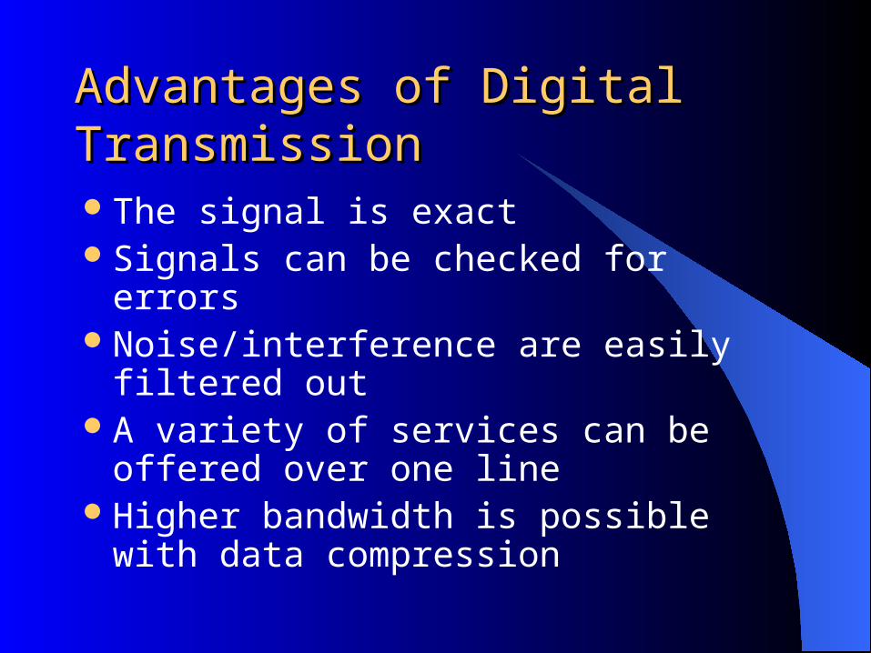
Advantages of Digital TransmissionAdvantages of Digital Transmission
The signal is exactSignals can be checked for errorsNoise/interference are easily filtered outA variety of services can be offered over
one lineHigher bandwidth is possible with data
compression
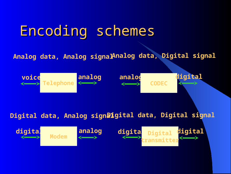
Encoding schemesEncoding schemes
voiceTelephone
analog
digitalModem
analog
analogCODEC
digital
digital Digitaltransmitter
digital
Analog data, Analog signal
Digital data, Analog signal Digital data, Digital signal
Analog data, Digital signal

Encoding and ModulationEncoding and Modulation
Encoder Decoder
Modulator Demodulator
digitalor
analog
digitalor
analog
digital
analog
g(t)
m(t)
fc
s(f)
x(t)
t
ffc
g(t)
m(t)
x(t)
s(t)
Why encoding?Why encoding?
Three factors determine successfulness of receiving a signal:
– S/N (Signal to Noise Ratio)
– Data rate– Bandwidth

Encoding Schemes' Evaluation FactorsEncoding Schemes' Evaluation Factors
Signal spectrum
Clocking
Error detection
Signal interference & noise immunity
Cost and complexity

Digital Data, Digital Signal / CharacteristicsDigital Data, Digital Signal / Characteristics
Digital signal– Uses discrete, discontinuous, voltage pulses
– Each pulse is a signal element
– Binary data is encoded into signal elements

Terms (1)Terms (1)
Unipolar– All signal elements have same sign
Polar– One logic state represented by positive voltage the
other by negative voltageData rate
– Rate of data transmission in bits per secondDuration or length of a bit
– Time taken for transmitter to emit the bit

Terms (2)Terms (2)
Modulation rate– Rate at which the signal level changes– Measured in baud = signal elements per
second
Mark and Space– Binary 1 and Binary 0 respectively
Interpreting SignalsInterpreting Signals
Need to know– Timing of bits - when they start and end– Signal levels
Factors affecting successful interpretation of signals:– Signal to noise ratio– Data rate– Bandwidth
Comparison of Encoding Schemes (1)Comparison of Encoding Schemes (1)
Signal Spectrum– Lack of high frequencies reduces required
bandwidth
– Lack of dc component allows ac coupling via transformer, providing isolation
– It is important to concentrate power in the middle of the bandwidth

Comparison of Encoding Schemes (2)Comparison of Encoding Schemes (2)
Clocking issues•Synchronizing transmitter and receiver is essential
•External clock is one way used for synchronization
•Synchronizing mechanism based on signal is also used & preferred (over using an external clock)

Spectral densitySpectral density
-0.5
0
0.5
1
1.5
0 0.5 1 1.5
NRZ-L,NRZI
B8ZS,HDB3
AMI, Pseudoternary
Manchester, Differential Manchester
Mea
n sq
uare
vol
tage
per
uni
t ban
dwid
th
Normalized frequency (f/r)

Comparison of Encoding Schemes (3)Comparison of Encoding Schemes (3)
Error detection– Can be built into signal encoding
Signal interference and noise immunity– Some codes are better than others
Cost and complexity– Higher signal rate (& thus data rate) lead to higher
costs– Some codes require signal rate greater than data
rate

Encoding SchemesEncoding Schemes
Nonreturn to Zero-Level (NRZ-L)Nonreturn to Zero Inverted (NRZI)Bipolar -AMI (Alternate Mark Inversion)PseudoternaryManchesterDifferential ManchesterB8ZSHDB3
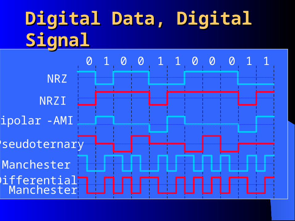
Digital Data, Digital SignalDigital Data, Digital Signal
0 1 0 0 1 1 0 0 0 1 1
NRZ
NRZI
Bipolar -AMI
Pseudoternary
ManchesterDifferentialManchester
Nonreturn to Zero-Level (NRZ-L)Nonreturn to Zero-Level (NRZ-L)
Two different voltages:– 0 - Low Level
– 1 - High Level
Voltage constant during bit interval
Most often, negative voltage for one value and positive for the other

Nonreturn to Zero InvertedNonreturn to Zero Inverted
Nonreturn to zero inverted on onesConstant voltage pulse for duration of bitData encoded as presence or absence of signal
transition at beginning of bit timeTransition (low to high or high to low) denotes
a binary 1No transition denotes binary 0An example of differential encoding (Data
represented by changes rather than levels)
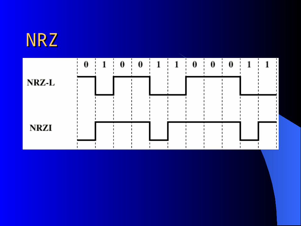
NRZNRZ

NRZ pros and consNRZ pros and cons
Pros– Easy to engineer– Makes good use of bandwidth
Cons– dc component– Lack of synchronization capability
Used for magnetic recordingNot often used for signal transmission

Bipolar-AMIBipolar-AMI
– Zero represented by no line signal
– One represented by positive or negative pulse
– One pulses alternate in polarity
– No loss of sync if a long string of ones happens (zeros still a problem)
– No net dc component Can use a transformer for isolating transmission line
– Lower bandwidth
– Easy error detection

PseudoternaryPseudoternary
One represented by absence of line signal
Zero represented by alternating positive and negative
No advantage or disadvantage over bipolar-AMI
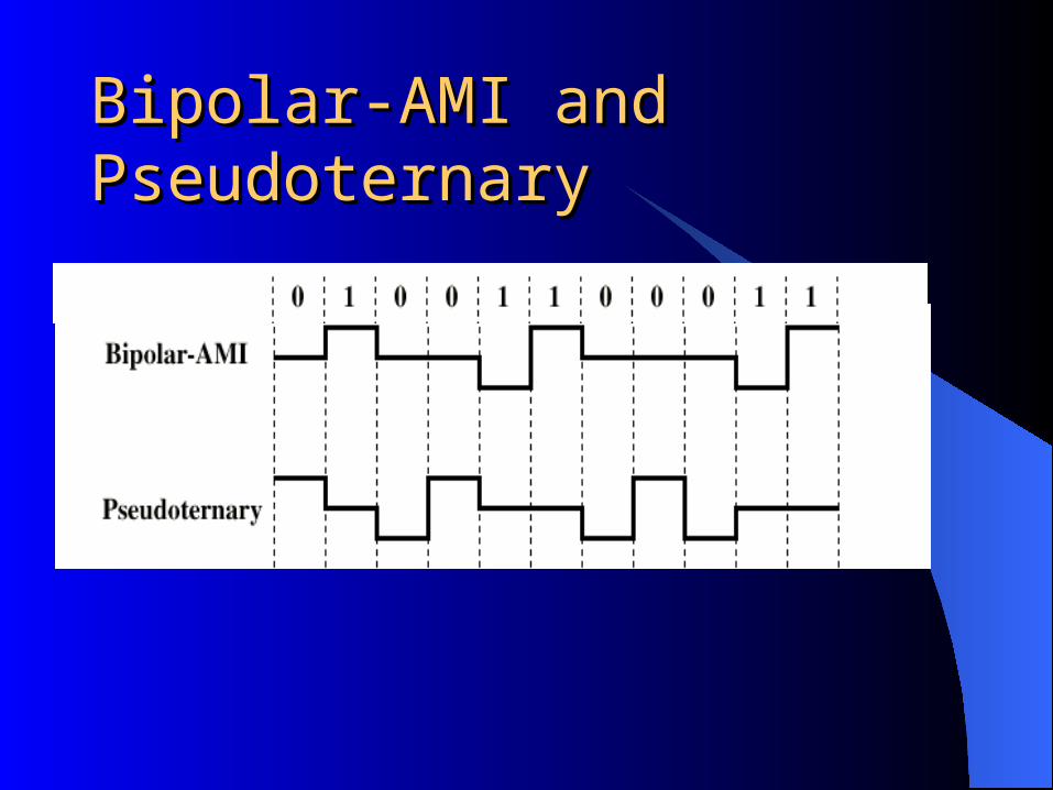
Bipolar-AMI and PseudoternaryBipolar-AMI and Pseudoternary

Trade Off for Multilevel BinaryTrade Off for Multilevel BinaryNot as efficient as NRZ
– With multi-level binary coding, the line signal may take on one of 3 levels, but each signal element, which could represent log23 = 1.58 bits of information, bears only one bit of information
– Receiver must distinguish between three levels : (+A, -A, 0)
– Requires approx. 3dB more signal power for same probability of bit error

BiphaseBiphase
Manchester– Transition in middle of each bit period– Transition serves as clock and data– One is represented by a transition from low to high
– Zero is represented by a transition from high to low Used by IEEE 802.3 (Ethernet)

Differential ManchesterDifferential Manchester
•Always a transition in the middle of the interval for clocking
•Transition at start of a bit period represents zero
•No transition at start of a bit period represents oneNote: this is a differential encoding scheme used by IEEE 802.5 (Token Ring)

Biphase Pros and ConsBiphase Pros and Cons Con
– At least one transition per bit time and possibly two– Maximum modulation rate is twice NRZ– Requires more bandwidth
Pros
– Synchronization on mid bit transition (self clocking)– No dc component– Error detection
Absence of expected transition points to error in transmission

Modulation RateModulation Rate
In General the Modulation Rate D = R/b where
R=Data Rate=bits/sec
b=number of bits per signal element
Data Rate (bit Rate 1/Tb) where Tb is bit duration
For Manchester Encoding maximum Rate is: 2/Tb
The modulation Rate is at which signal elements are generated

Scrambling TechniquesScrambling Techniques Used to reduce signaling rate relative to the
data rate by replacing sequences that would produce constant voltage for a priod of time with a filling sequence that accomplishes the following goals:– Must produce enough transitions to maintain
synchronization
– Must be recognized by receiver and replaced with original data sequence
– is same length as original sequence

Scrambling TechniquesScrambling Techniques
•No dc component
•No long sequences of zero level line signal
•No reduction in data rate
•Error detection capability•As an example, fax machines use the modified Huffman code to accomplish this.

B8ZSB8ZS B8ZS: Abbreviation for bipolar with eight-zero substitution Same as Bipolar AMI with 8 Zeros Substitution Based on Bipolar-AMI If octet of all zeros and last voltage pulse preceding was
positive, encode as 000+-0-+ If octet of all zeros and last voltage pulse preceding was
negative, encode as 000-+0+- Causes two violations of AMI code This is unlikely to occur as a result of noise Receiver detects and interprets the sequence as octet of
all zeros

B8ZSB8ZS•A one is sent on a T1 by sending a pulse, as opposed to not sending a pulse.
•The alternating mark rule means that if the last pulse sent was of a positive going polarity, the next pulse sent must be negative going.
•If a T1 device receives two pulses in a row and they are of the same polarity a bipolar violation (BPV) has occurred.
•In B8ZS a specific combination of valid pulses and bipolar violations is used to represent a string of eight zeroes, whenever the user data contains eight zeroes in a row

B8ZSB8ZSSince a T1 uses a single pair of wires in each direction and the only signals on those wires are the pulses which represent data; the only way to recover clock and retain synchronization on a T1 is by detecting the rate at which pulses are being received. All of the equipment in a T1 circuit must operate at the same rate because all of the equipment must sense the T1 at the correct time in order to determine if a pulse (1) or no pulse (0) has been received at each bit time.
Since only ones are sent as pulses and zeroes are represented by doing nothing, if too many zeroes are sent at a time there will be no pulses on the T1 at all and the clock circuitry in all of the hardware will rapidly fall out of synchronization. Thus the design of AMI requires that a certain ONES DENSITY be maintained, that a certain minimum of the bits over a certain period of time be guaranteed to be a ONE (pulse). This is why AMI circuits require DENSITY enforcement

B8ZSB8ZS
Briefly stated; on average one bit in eight must be a one and no more than (varies according to specific standard) so many zeroes may be sent in a row. In order to be able to satisfy the ones density requirement on an AMI T1 one bit out of every eight is taken away from the user, not available for voice or data traffic, and that 1 bit in 8 is always sent as a one. Once this has been done the requirement for ones density is satisfied and the user is free to send any data pattern in the remaining bandwidth.
B8ZSB8ZS
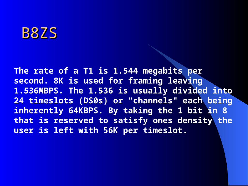
The rate of a T1 is 1.544 megabits per second. 8K is used for framing leaving 1.536MBPS. The 1.536 is usually divided into 24 timeslots (DS0s) or "channels" each being inherently 64KBPS. By taking the 1 bit in 8 that is reserved to satisfy ones density the user is left with 56K per timeslot.
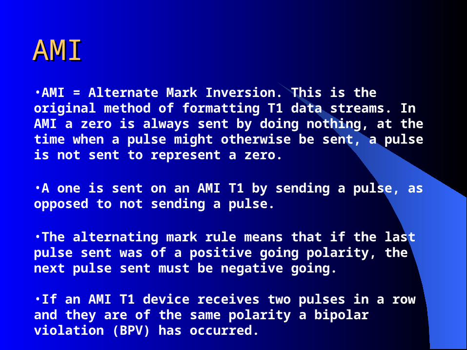
AMIAMI•AMI = Alternate Mark Inversion. This is the original method of formatting T1 data streams. In AMI a zero is always sent by doing nothing, at the time when a pulse might otherwise be sent, a pulse is not sent to represent a zero.
•A one is sent on an AMI T1 by sending a pulse, as opposed to not sending a pulse.
•The alternating mark rule means that if the last pulse sent was of a positive going polarity, the next pulse sent must be negative going.
•If an AMI T1 device receives two pulses in a row and they are of the same polarity a bipolar violation (BPV) has occurred.
•Thus AMI has a rudimentary error checking capability with a 50% probability of detecting altered, inserted or lost bits end to end.

ESFESFExtended Super Frame
A DS level and framing specification for synchronous digital streams over circuits in the North America. A DS1 "frame" is composed of 24 eight-bit bytes plus one framing bit (193 bits). 8000 bytes per second come from each source, and thus 8000 frames per second are transported by the DS1 signal. The result is 193*8000 = 1,544,000 bits per second.
In the original standard, the framing bits continuously repeated the sequence 110111001000, and such a 12-frame unit is called a super-frame. In voice telephony, errors are acceptable (early standards allowed as much as one frame in six to be missing entirely), so the least significant bit in two of the 24 streams was used for signaling between network equipments. This is called robbed bit signaling

ESFESF
To promote error-free transmission, an alternative called the extended super-frame (ESF) of 24 frames was developed. In this standard, six of the 24 framing bits provide a six bit cyclic redundancy check(CRC-6), and six provide the actual framing. The other 12 form a virtual circuit of 4000 bits per second for use by the transmission equipment, for call progress signals such as busy, idle and ringing. DS1 signals using ESF equipment are nearly error-free, because the CRC detects errors and allows automatic re-routing of connections.

HDB3HDB3 High Density Bipolar 3 Zeros Based on bipolar-AMI String of four zeros replaced with one or two
pulses
Note: The following is the explanation for the HDB3 code example on the next slide (see rules in Table 5.4, page 142):
Assuming that an odd number of 1's have occurred since the last substitution, since the polarity of the preceding pulse is "-", then the first 4 zeros are replaced by "000-". For the next 4 zeros, since there have been no Bipolar pulses since the 1st substitution, then they are replaced by"+00+" since the preceding pulse is a "-". For the 3rd case where 4 zeros happen, 2 (even) Bipolar pulses have happened since the last substitution and the polarity of the preceding pulse is "+", so "-00-" is substituted for the zeros.

B8ZS and HDB3B8ZS and HDB3
(Assume odd number of 1s
since last substitution)
See Table 5.4 for HDB3 Substitution Rules

Digital Data, Analog SignalDigital Data, Analog Signal
Transmitting digital data through PSTN (Public telephone system)
– 300Hz to 3400Hz bandwidth– modem (modulator-demodulator) is used to
convert digital data to analog signal and vice versa Three basic modulation techniques are used: Amplitude shift keying (ASK) Frequency shift keying (FSK) Phase shift keying (PSK)

Modulation TechniquesModulation Techniques

Amplitude Shift KeyingAmplitude Shift Keying
Values represented by different amplitudes of carrier
Usually, one amplitude is zero– i.e. presence and absence of carrier is used
Susceptible to sudden gain changesInefficientUp to 1200bps on voice grade linesUsed over optical fiber

ASKASKVd(t)
Vc(t)
VASK(t)
fcfc-f0fc-3f0 fc+f0 fc+3f0
Signalpower
Frequency
frequency spectrum

Frequency Shift KeyingFrequency Shift Keying
Values represented by different frequencies (near carrier)
Less susceptible to error than ASKUp to 1200bps on voice grade linesHigh frequency radio (3-30 MHz)Higher frequency on LANs using co-ax

FSKFSK
Carrier 2
Datasignal
Carrier 1
vd(t)
v1(t)
v2(t)
FSK(t)
f1
Signalpower
Frequency
frequency spectrum
f2

FSK FSK in modemin modem (on Voice Grade Line) (on Voice Grade Line)
400
980(1070)
1850(2225)
1180(1270)
1650(2025)
3400
Amplitude
Frequency(Hz)
PSTN bandwidth
frequency spectrumfrequency spectrum

Phase Shift KeyingPhase Shift Keying
Phase of carrier signal is shifted to represent data
Differential PSK– Phase shifted relative to previous transmission
rather than some reference signal
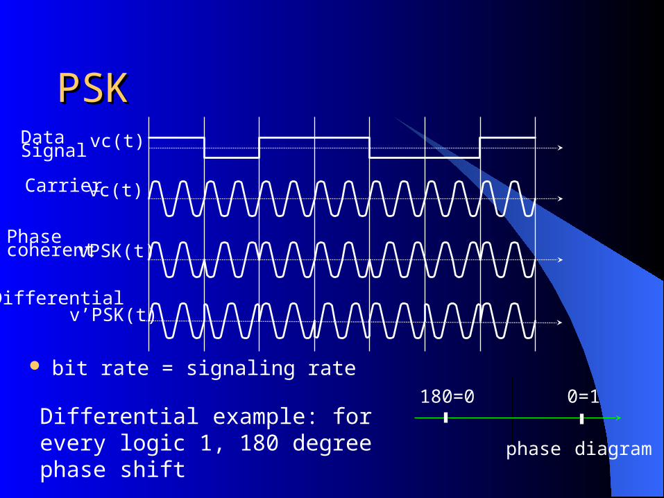
PSKPSKDataSignal
Carrier
Phasecoherent
Differential
vc(t)
vc(t)
vPSK(t)
v’PSK(t)
180=0 0=1
phase diagram
bit rate = signaling rate
Differential example: for every logic 1, 180 degree phase shift
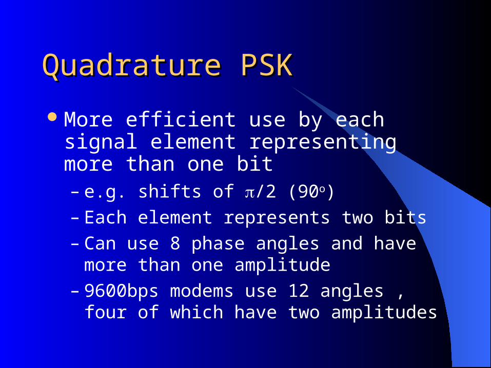
Quadrature PSKQuadrature PSK
More efficient use by each signal element representing more than one bit– e.g. shifts of /2 (90o)– Each element represents two bits– Can use 8 phase angles and have more than
one amplitude– 9600bps modems use 12 angles , four of
which have two amplitudes
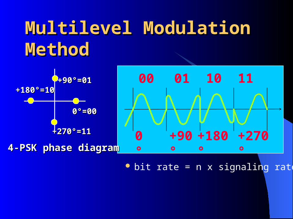
Multilevel Modulation MethodMultilevel Modulation Method
01 1000
0°
+90°
+180°
+270°
11
bit rate = n x signaling rate
+90°=01+90°=01
0°=000°=00
+270°=11+270°=11
+180°=10+180°=10
4-PSK phase diagram4-PSK phase diagram

Performance of Digital to Performance of Digital to Analog Modulation SchemesAnalog Modulation Schemes Bandwidth
– ASK and PSK bandwidth directly related to bit rate
– FSK bandwidth related to data rate for lower frequencies
– Requires more analog bandwidth than ASK In the presence of noise, bit error rate of PSK and
QPSK are about 3dB superior to ASK and FSK

Analog Data, Digital SignalAnalog Data, Digital Signal
Digitization– Conversion of analog data into digital data– Digital data can then be transmitted using NRZ-L
or using other codes– Digital data can then be converted to analog signal– Analog to digital conversion done using a CODEC– Pulse code modulation– Delta modulation
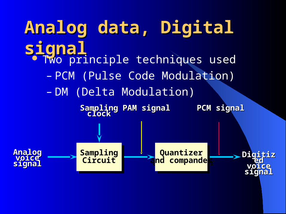
Analog data, Digital signalAnalog data, Digital signal Two principle techniques used
– PCM (Pulse Code Modulation)– DM (Delta Modulation)
AnalogAnalogvoicevoice signalsignal
Sampling Sampling clockclock
PAMPAM signalsignal PCMPCM signalsignal
SamplingCircuit
SamplingCircuit
Quantizerand compander
Quantizerand compander
DigitizedDigitizedvoicevoice signalsignal
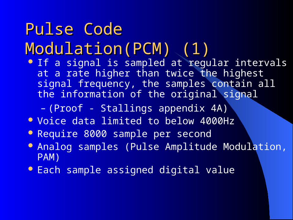
Pulse Code Modulation(PCM) (1)Pulse Code Modulation(PCM) (1) If a signal is sampled at regular intervals at a rate
higher than twice the highest signal frequency, the samples contain all the information of the original signal
– (Proof - Stallings appendix 4A) Voice data limited to below 4000Hz Require 8000 sample per second Analog samples (Pulse Amplitude Modulation, PAM) Each sample assigned digital value
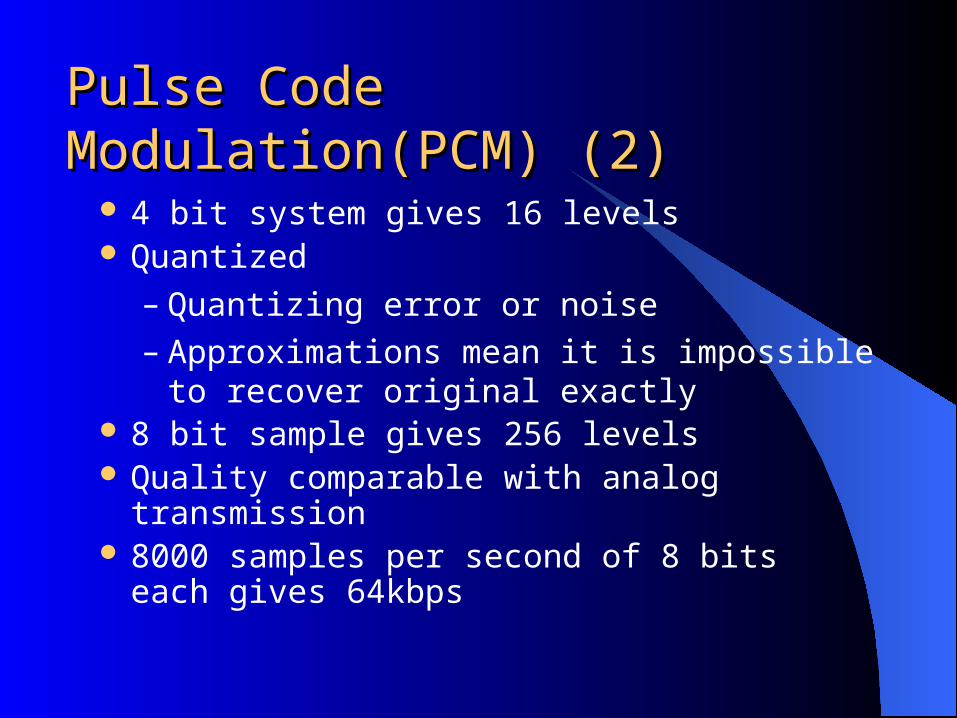
Pulse Code Modulation(PCM) (2)Pulse Code Modulation(PCM) (2)
4 bit system gives 16 levels Quantized
– Quantizing error or noise– Approximations mean it is impossible to
recover original exactly 8 bit sample gives 256 levels Quality comparable with analog transmission 8000 samples per second of 8 bits each gives
64kbps

The process starts with an analog signal, which is sampled by PAM sample. the resulting pulse are quantized to produced PCM pulses and then encoded to produce bit stream. At the receiver end, the process is reversed to reproduce the analog signal.
Pulse Code Modulation(PCM) (3)
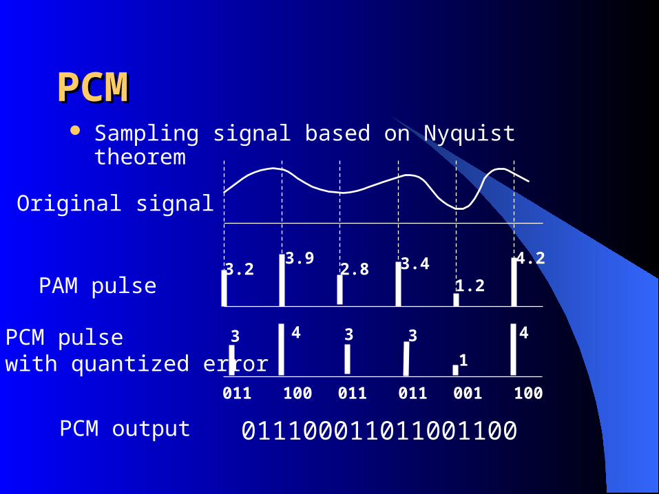
PCMPCM Sampling signal based on Nyquist theorem
3.23.9
2.8 3.41.2
4.2
3 4 3 3
1
4
011 100 011 011 001 100
Original signal
PAM pulse
PCM pulse with quantized error
011100011011001100 PCM output
Nonlinear EncodingNonlinear Encoding
Quantization levels are not necessarily equally spaced. The problem with equal spacing is that the mean absolute error for each sample is the same, regardless the signal level. Lower amplitude values are relatively more distorted.
Nonlinear encoding reduces overall signal distortion
Can also be done by companding
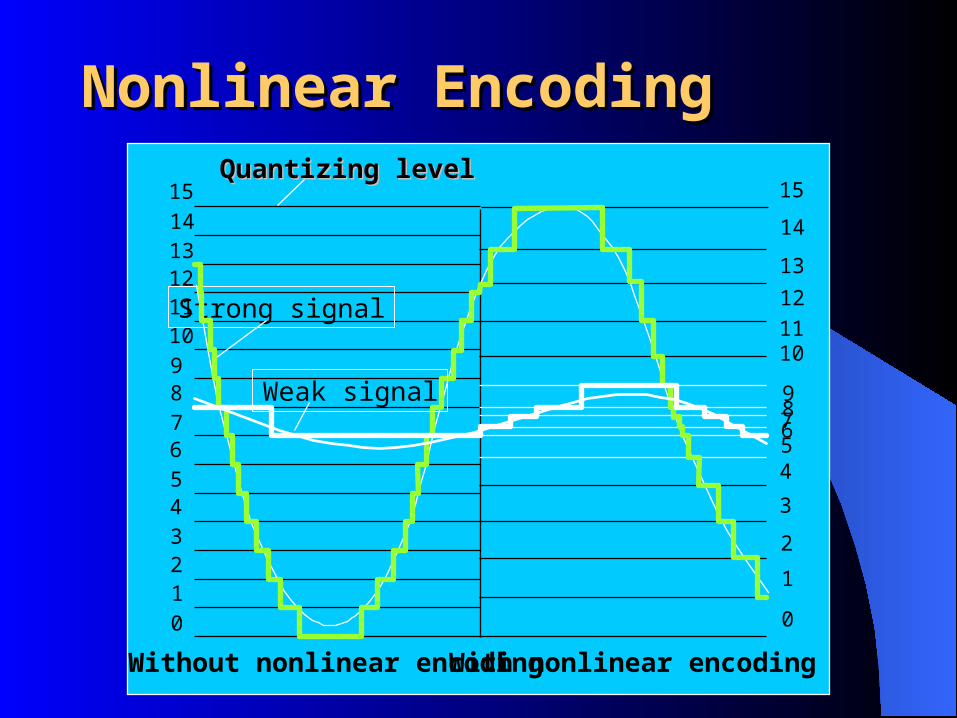
Nonlinear EncodingNonlinear Encoding
0123456789101112131415
Strong signal
Weak signal
0
1
2
3
456789
101112
13
14
15Quantizing levelQuantizing level
Without nonlinear encoding With nonlinear encoding

Prior to the input signal being sampled and converted by ADC into a digital form, it is passed through a circuit known as a compressor. Similarly, at the destination, the reverse operation is perform on the output of the DAC by a circuit known as expander.
Nonlinear Encoding
Delta ModulationDelta Modulation
Analog input is approximated by a staircase function
Move up or down one level () at each sample interval
Binary behavior– Function moves up or down at each sample
interval

Delta Modulation - exampleDelta Modulation - example

Delta Modulation - Delta Modulation - PerformancePerformanceGood voice reproduction
– PCM - 128 levels (7 bit)– Voice bandwidth 4khz– Should be 8000 x 7 = 56kbps for PCM
Data compression can improve on this– e.g. Interframe coding techniques for video

Analog Data, Analog SignalsAnalog Data, Analog Signals
Why modulate analog signals?– Higher frequency can give more efficient
transmission– Permits frequency division multiplexing
Types of modulation– Amplitude– Frequency– Phase

Multilevel Modulation MethodMultilevel Modulation Method
16-QAM phase diagram16-QAM phase diagram
Quadrature Amplitude Modulation (QAM)Combines differential phase and amplitude shifts to achieve 16 distinct states, thereby allowing 4 bits to be represented by a single signal

V.34 ModulationV.34 Modulation V.34 Also known as V.FAST. It will allow modems to operate at 28Kb/s. Uses multidimensional trellis coding and line probing equalization, power control and framing. Adaptive Pre-Emphasis or Precoding is a new form of adaptive equalization that modifies the transmitted signal as well as the receiver. Trellis Coding in more complex forms (64-state 4D, 32-state 4D, etc.) make more efficient use of constellation space. Non-linear encoding wraps the constellation space to bring the inner points closer and increase the distance between the outer points. Shell Mapping forms circular constellations which are optimum shape. Shaping distributes consolation points nearer the center, which is less sensitive to noise. Adaptive Power Control changes the levels to produce the best performance over impaired channels. This capability may also improve performance over analog cellular services. Scaling maintains the best transmit power levels when different modulation technologies are employed. Framing encodes bits over multiple symbols. This increases the systems ability to support different combinations of symbol and data rates and makes it possible to integrate a secondary channel. V.FC V.FAST Class developed by Rockwell International. It is based on the V.34 proposed design, but it is an interim solution. It does not support the V.8 handshaking mechanism for full V.34 compatibility (it will require a software modification) V.8 negotiation using a modulated calling tone and answer tone transfers information about two modem’s functional capabilities in 5 seconds or less.

The 56K ModemThe 56K Modem
The V.90 modulation uses PAM. Each symbol is a different voltage level. 128 symbols multiplied by 8000 symbols per second, gives a 56,000 bits per second downstream rate.
If the environment is noisy, less voltage levels are used. For example, if 64 are in use, then the speed will be 48,000 bits per second in a 56Kbps connection, the server is a digital modem. The PAM modulation requires at least 45dB SNR. The minimum RX level a receiver can pull in is 34db below TX.
For upstream transmission, the information is transmitted in the old way, analog, using QAM, A2D, through the PSTN, D2A and analog again. The upstream rate is limited to 31.2Kbps

END ClassEND Class
Related Documents