1 www.xsens.com MT Low Level Communication Protocol Documentation MTi 1/10/100/600-series Document MT0101P, Revision 2019.A, Dec 2019

Welcome message from author
This document is posted to help you gain knowledge. Please leave a comment to let me know what you think about it! Share it to your friends and learn new things together.
Transcript

1 www.xsens.com
MT Low Level
Communication Protocol
Documentation
MTi 1/10/100/600-series
Document MT0101P, Revision 2019.A, Dec 2019

2 www.xsens.com
Revision Date By Changes
A 3 June 2005 SSM First version
2018.C 25 June 2018 SGI, THO Corrected string formats of $PCTF and
$XSVEL
Added HR output details for MTi 1-series v2
Updated behaviour of SendLatest for PVT
data
Updated SetOutputConfiguration behavior
2019.A 11 Jan 2019 SGI, MCR Added AccelerationHR and RateOfTurnHR
for 10-series; improved general description.
Added OptionFlags:
EnableOrientationSmoother and
EnableConfigMessageAtStartup
Added MTData2 identifiers: XDI_DeviceId,
XDI_LocationId
Added status flag: HaveGnssTimePulse
SGI Added information on wraparound of
SampleTimeFine
Fixed errors in Table 25: Contents of
GnssPvtData
Added MTi 600-series and Req/Set
PortConfig, Req/Set CanOutputConfig and
Req/Set CanConfig
2019.B 11 sept 2019 AKO Added documentation references
2019.C Dec 2019 AKO Xsens brand update
© 2005-2020, Xsens Technologies B.V. All rights reserved. Information in this document is subject to change
without notice. Xsens, Xsens DOT, MVN, MotionGrid, MTi, MTi-G, MTx, MTw, Awinda and KiC are registered trademarks or trademarks of Xsens Technologies B.V. and/or its parent, subsidiaries and/or affiliates in The Netherlands, the USA and/or other countries. All other trademarks are the property of their respective owners.

3 www.xsens.com
Table of Contents
1 Terms, abbreviations and references ........................................ 6
2 Xsens Help Center and User Community ................................... 7
3 Introduction .............................................................................. 8
4 States ...................................................................................... 10
4.1 Config State ............................................................................................. 10
4.2 Measurement State ................................................................................... 11
5 Messages ................................................................................ 13
5.1 Message structure ..................................................................................... 13 5.1.1 Big endian output format ...................................................................... 14
5.2 Message usage .......................................................................................... 15
5.3 Message listing ......................................................................................... 16 5.3.1 WakeUp + State messages ................................................................... 16 5.3.2 Informational messages ........................................................................ 17 5.3.3 Device-specific messages ...................................................................... 21 5.3.4 Synchronization messages .................................................................... 26 5.3.5 Configuration messages ........................................................................ 29 5.3.6 Data-related messages ......................................................................... 10 5.3.7 Filter messages ................................................................................... 19
6 MT low level communication protocol example ....................... 29
7 Miscellaneous .......................................................................... 31
7.1 Default factory settings .............................................................................. 31
7.2 Restore communication .............................................................................. 31 7.2.1 Default communication settings ............................................................. 32
8 Message Reference Listing ...................................................... 33
8.1 WakeUp and State messages (Section 5.3.1) ................................................ 33
8.2 Informational messages (Section 5.3.2) ....................................................... 33
8.3 Device-specific messages (Section 5.3.3) ..................................................... 33
8.4 Synchronization messages (Section 5.3.4) .................................................... 35
8.5 Configuration messages (Section 5.3.5) ....................................................... 35
8.6 Data-related messages (Section 5.3.6) ........................................................ 36
8.7 Filter messages (Section 5.3.7) ................................................................... 37

4 www.xsens.com
List of Tables
Table 1: MTi product documentation overview ........................................................... 7 Table 2: Default configuration of MTi devices ........................................................... 11 Table 3: Construction of an Xbus message ............................................................... 13 Table 4: Structure of FirmwareRev message ............................................................ 19 Table 5: Error codes sent by the MTi ....................................................................... 20 Table 6: Warning codes sent by the MTi .................................................................. 21 Table 7: Available baud rates ................................................................................. 22 Table 8: Options to handle errors ........................................................................... 23 Table 9: Descriptions of the Option Flags ................................................................. 23 Table 10: Sync in settings ..................................................................................... 27 Table 11: Sync out settings ................................................................................... 27 Table 12: Available sync functions .......................................................................... 27 Table 13: Available synchronization lines ................................................................. 29 Table 14: The contents of the configuration message (CONFIGURATION) .................... 30 Table 15: The contents of the configuration message (CONFIGURATION) for MTi-600s .. 30 Table 16: Contents of an MTData2 packet setting in [Set/Req]OutputConfiguration ...... 31 Table 17: Available MTData2 packets ...................................................................... 33 Table 18: Settings for MTData2 Data Identifier ......................................................... 35 Table 19: Available output period for String Output types ........................................... 5 Table 20: Use of Output Skipfactor with String Outputs .............................................. 6 Table 21: List of alignment matrices designations ...................................................... 7 Table 22: Settings of Extended Output Mode ............................................................ 8 Table 23: AccelerationHR output specifications ......................................................... 14 Table 24: RateOfTurnHR output specifications .......................................................... 15 Table 25: Contents of GnssPvtData ......................................................................... 15 Table 26: Contents of GnssSatInfo ......................................................................... 16 Table 27: Contents of StatusWord .......................................................................... 18 Table 28: Structure of stored LatLonAlt value ........................................................... 20 Table 29: Structure of the AvailableFilterProfiles message ......................................... 21 Table 30: List of available filter profiles ................................................................... 22 Table 31: List of available platforms for GNSS receiver .............................................. 24 Table 32: Available orientation resets ..................................................................... 25 Table 33: Minimum and maximum correction ticks for AdjustUTCTime ........................ 26 Table 34: Structure of UTCTime ............................................................................. 26 Table 35: Available commands for IccCommand ....................................................... 27 Table 36: ICC RESULT communicated with IccCommandAck ...................................... 27 Table 37: Payload of IccCommandAck ..................................................................... 27 Table 38: ICCRESULTS .......................................................................................... 28 Table 39: Default factory settings ........................................................................... 31 Table 40: Default settings after a restore communication procedure ........................... 31 Table 41: Default communication options (serial interface) ........................................ 32

5 www.xsens.com
List of Figures Figure 1: The WakeUp procedure of the MTi ............................................................. 10 Figure 2: Port Configuration .................................................................................... 9 Figure 3: Flow chart for data format selection. ......................................................... 10 Figure 4: Structure of an MTData2 message ............................................................ 11 Figure 5: The low-level communication emulator (Device Data Viewer) in MT Manager .. 29
6 www.xsens.com
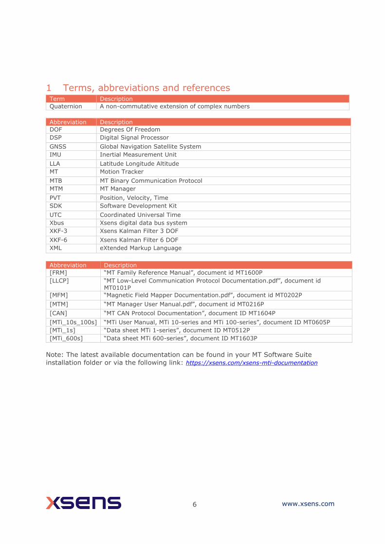
1 Terms, abbreviations and references Term Description
Quaternion A non-commutative extension of complex numbers
Abbreviation Description
DOF Degrees Of Freedom
DSP Digital Signal Processor
GNSS Global Navigation Satellite System
IMU Inertial Measurement Unit
LLA Latitude Longitude Altitude
MT Motion Tracker
MTB MT Binary Communication Protocol
MTM MT Manager
PVT Position, Velocity, Time
SDK Software Development Kit
UTC Coordinated Universal Time
Xbus Xsens digital data bus system
XKF-3 Xsens Kalman Filter 3 DOF
XKF-6 Xsens Kalman Filter 6 DOF
XML eXtended Markup Language
Abbreviation Description
[FRM] “MT Family Reference Manual”, document id MT1600P
[LLCP] “MT Low-Level Communication Protocol Documentation.pdf”, document id MT0101P
[MFM] “Magnetic Field Mapper Documentation.pdf”, document id MT0202P
[MTM] “MT Manager User Manual.pdf”, document id MT0216P
[CAN] “MT CAN Protocol Documentation”, document ID MT1604P
[MTi_10s_100s] “MTi User Manual, MTi 10-series and MTi 100-series”, document ID MT0605P
[MTi_1s] “Data sheet MTi 1-series”, document ID MT0512P
[MTi_600s] “Data sheet MTi 600-series”, document ID MT1603P
Note: The latest available documentation can be found in your MT Software Suite
installation folder or via the following link: https://xsens.com/xsens-mti-documentation

7 www.xsens.com
2 Xsens Help Center and User Community Xsens has an extensive help center, a place where users of Xsens and Xsens employees
(support, field application engineers, sales and R&D engineers) meet. The knowledge
base contains tips and tricks, guidance and answers to frequently asked questions. News
is also shared at the knowledge base and it is possible to ask additional questions
(registration required).
The user community is the place to ask questions. Answers may be given by other users
or by Xsens employees. The response time in the user community is significantly shorter
than the response time at Xsens support.
The knowledge base and user community are searchable simultaneously. A search query
thus shows results irrespective of the source.
Please visit https://base.xsens.com to complete your 1 minute registration.
Table 1 summarizes all available official documents for the Xsens MTi product line.
Table 1: MTi product documentation overview
MTi 1-series MTi 600-series MTi 10/100-series
MTi Family Reference Manual MTi User Manual
MTi 1-series Datasheet MTi 600-series Datasheet
MTi 1-series DK User Manual MTi 600-series DK User Manual
MTi 1-series HW Integration Manual
MTi 600-series HW Integration Manual
MT CAN protocol Documentation
MT Manager Manual
Magnetic Calibration Manual
MT Low Level Communication Protocol Documentation
Firmware Updater User Manual

8 www.xsens.com
3 Introduction
This document describes how to communicate with Xsens’ range of miniature MEMS
based inertial Motion Trackers; MTi 1-series, MTi 10-series, MTi 100-series (including
MTi-G-710 GNSS/INS) and MTi 600-series. These Motion Trackers (or MTs) all use a
common binary communication protocol called the “XBus Protocol”. Knowledge of this
protocol is important if you wish to directly communicate to an MT on low-level basis
using the I2C, SPI, UART, RS-232, RS-485, RS-422 or USB interfaces. The MT
communication protocol based message enables the user to change the configuration of
the MTi’s and retrieve the output data. For I2C and SPI interfaces, refer to [MTi_1s] for
more information on the MTSSP protocol.
Note: not all products support the same functionality. There are 11 different products
described in this document, the description of each message ID contains a table showing
the supported products:
1 2 3 7 10 20 30 100 200 300 710 610 620 630 670
The numbers in this table correspond to the following products:
• 1: MTi-1 IMU
• 2: MTi-2 VRU
• 3: MTi-3 AHRS
• 7: MTi-7 GNSS/INS
• 10: MTi-10 IMU
• 20: MTi-20 VRU
• 30: MTi-30 AHRS
• 100: MTi-100 IMU
• 200: MTi-200 VRU
• 300: MTi-300 AHRS
• 710: MTi-G-710 GNSS/INS
• 610: MTi-610 IMU
• 620: MTi-620 VRU
• 630: MTi-630 AHRS
• 670: MTi-670 GNSS/INS
An empty field indicates that the corresponding product does not support the message.
The configuration settings are all user-settable using the communication protocol.
Examples are output frequency, input and output synchronization, baud rate and output
configuration. The different output modes enable the user to change the output data to
the one that is preferred.
Configuration changes are executed in the so-called “Config State”. In this state the MT
accepts messages that set the output mode or other settings. Once the preferred
configuration is set the user can set the MT into the “Measurement State”. In the
Measurement State the MT starts outputting the data based on the applied configuration
settings. The MT states are discussed in the Section 4.

9 www.xsens.com
The messages used in Config and Measurement state are described in Section 5. In
this section, the generic message format is explained and all messages are described
grouped by functionality.
Section 6 lists some examples of how to use the MT binary data communication protocol.
Additional information about the MT such as a list of factory default values and table of
maximum sample frequencies can be found in section 7. The last section gives a
message reference overview of the MT messages with short descriptions, see section 8.

10 www.xsens.com
4 States The MT has two states, i.e. Config and Measurement state. In the Config State various
settings can be read and written and in the Measurement state the MT will output its
data message which contains data dependent on the current configuration.
There are two different ways to enter the Config State or the Measurement State. At
power-up the MT starts the WakeUp procedure and it will send the WakeUp message. If
no action is taken and the OptionFlag is not set to DisableAutoMeasurement, the device
enters the Measurement State. If the WakeUpAck message is sent within 500ms after
reception of the WakeUp message the MT enters the Config State.
Prior to entering the Measurement State, the Configuration and eMTS (extended Motion
Tracker Settings messages) are sent to the host. The MTi 10-series, MTi 100-series and
MTi 600-series will send these messages by default. For the MTi 1-series, these startup
messages can be enabled or disabled using the setOptionFlags command. Configuration
data is the configuration that is read from the internal non-volatile memory and will be
used in the Measurement State. The data in the Configuration message can always be
used to determine the output configuration. Another way to enter Config State or
Measurement State is to use the GoToConfig or GoToMeasurement messages. The
encrypted eMTS data is required to be able to process the data by Xsens software to
calculate calibrated inertial data values. Settings in the eMTS data are used to estimate
orientation and position.
Another way to enter the Config or Measurement State is to use the GoToConfig or
GoToMeasurement messages while the other state is active.
Figure 1: The WakeUp procedure of the MTi
4.1 Config State
Config State is used to get and/or set various settings of the MT. Most of the settings will
change the configuration which defines the device functionality in Measurement State.
Settings that change the configuration are for example the communication baud rate,
sample period, output mode, output settings or synchronization properties.
At power-up all settings are read from non-volatile memory. All settings are stored in a
format developed by Xsens known as the eMTS (extended Motion Tracker Specification),
Measurement
WakeUp
procedure
WakeUpAck
received by device
No WakeUpAck
received by device
GotoMeasurement
GotoConfig
Config
11 www.xsens.com
along with other device specific data such as calibration parameters. The format is
proprietary, but all settings can be manipulated by using the appropriate Set messages.
Settings changed in Config State are immediately stored in the memory. The memory will
retain the latest values even if the device is disconnected from power. Some messages
have an additional parameter that requires the user to explicitly specify whether the
new values should be stored in non-volatile memory or not. The setting changes are
immediate.
NOTE: There is one exception, namely the baud rate setting. The new setting will not be
applied immediately, it will be used at the next power-cycle or after a soft-reset.
4.2 Measurement State
In the Measurement State the MT will output its data to the host in a way depending on
the configuration settings defined in the Config State. A single message, MTData2, is used
for all different data outputs. It is therefore important that the host knows how the
device is configured. The current configuration will determine how the message data
should be interpreted. A special message, Configuration, contains the information
which with the data received by the host in Measurement State can be unambiguously
interpreted. When logging MTData2 messages it is advisable to include the
Configuration message in the data header for future analysis or post-processing.
If the host does not respond to the WakeUp message at power-up (or after issuing a
Reset message) the MT will automatically enter the Measurement State. Just before
entering the Measurement State it will send the Configuration message. The
configuration settings are all read from the non-volatile memory and are used during
operation.
Table 2: Default configuration of MTi devices
Property MTi-1/10/100/610 IMU
MTi-2/20/200/620 VRU MTi-3/30/300/630 AHRS
MTi-7/670/G-710 GNSS/INS
Output
Configuration
Quaternion: float Quaternion: float
Delta_q: float
Delta_v: float
Mag Field: Float
Packet counter Packet counter Packet counter
Sample Time Fine Sample Time Fine Sample Time Fine
Status Word Status Word Status Word
AltitudeEllipsoid:FP1632
LatLon: FP1632
VelocityXYZ: FP1632
Setting profile
N/A • VRU_General (MTi-2/20/200 VRU)
• Responsive/VRU (MTi-620 VRU)
• General (MTi-3/30/300
AHRS)
General
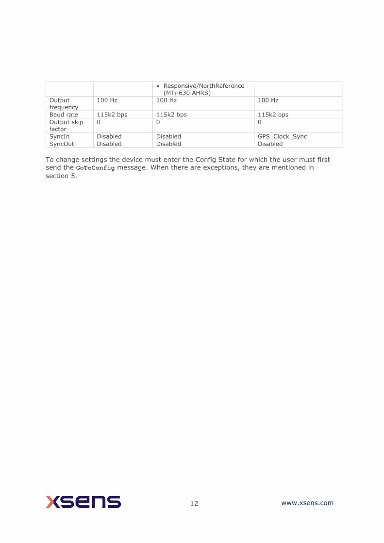
12 www.xsens.com
• Responsive/NorthReference (MTi-630 AHRS)
Output frequency
100 Hz 100 Hz 100 Hz
Baud rate 115k2 bps 115k2 bps 115k2 bps
Output skip factor
0 0 0
SyncIn Disabled Disabled GPS_Clock_Sync
SyncOut Disabled Disabled Disabled
To change settings the device must enter the Config State for which the user must first
send the GoToConfig message. When there are exceptions, they are mentioned in
section 5.

13 www.xsens.com
5 Messages
5.1 Message structure
The communication with the MT is done by messages which are built according to a
standard structure. The message has two basic structures; one with a standard length
and one with extended length. The standard length message has a maximum of 254 data
bytes and is used most frequently. In some cases the extended length message needs to
be used if the number of data bytes exceeds 254 bytes.
An MT message (standard length) contains the following fields:
Xbus header
Preamble BID MID LEN DATA CHECKSUM
An MT message (extended length) contains these fields:
Preamble BID MID LEN LENext DATA CHECKSUM
Table 3: Construction of an Xbus message
Preamble
Every message starts with the preamble. This field always contains the value 250
(=0xFA).
BID or Address
A stand-alone MT has a BID value of 1 (0x01) indicating “first device”. A stand-alone MT
device is however also a “master device” on its own bus and it can therefore also be
addressed using the BID value 255 (0xFF) indicating a “master device”.
An MT will only acknowledge a message (reply) if it is addressed with a valid BID. An MT
will always acknowledge a message with the same BID that has been used to address it.
Field Field width Description
Preamble 1 byte Indicator of start of packet → 250 (0xFA)
BID 1 byte Bus identifier or Address → 255 (0xFF)
MID 1 byte Message identifier
LEN 1 byte For standard length message: Value equals number of bytes in DATA field. Maximum value is 254 (0xFE) For extended length message: Field value is always 255 (0xFF)
EXT LEN 2 bytes 16 bit value representing the number of data
bytes for extended length messages. Maximum value is 2048 (0x0800)
IND ID 1 byte The type of indication received
DATA
(standard length)
0 – 254 bytes Data bytes (optional)
DATA
(extended length)
255 – 2048
bytes
Data bytes
Checksum 1 byte Checksum of message
14 www.xsens.com
For example, this means that the same device can be addressed using a BID of 255
(0xFF) as well as 1 (0x01), and it will reply appropriately with the corresponding BID.
Note however, that messages generated by the MT itself (i.e. not in acknowledge on a
request) will always have a BID of 255 (0xFF). In practice, the only message for which
this occurs is the MTData2 messages.
Message Identifier (MID)
This message field identifies the kind of message. For a complete listing of all possible
messages see section 5.3.
Length (LEN)
Specifies the number of data bytes in the DATA field for standard length message. If
value 255 (=0xFF) is specified the message will be interpreted as an extended message
length and the next two bytes are used for the number of bytes in the DATA field. If zero,
no DATA field exists.
Extended Length (EXT LEN)
This field is a 16 bit value representing the number of data bytes in the DATA field of an
extended length message.
Indication Identifier (IND ID)
This field is an 8-bit value that contains the ID of the indication that was received.
Indication Identifiers are similar to Message Identifiers.
Data (DATA)
This field contains the data bytes and it has a variable length which is specified in the
Length or Extended Length field. The interpretation of the data bytes is message specific,
i.e. depending on the MID value the meaning of the data bytes is different. The data is
always transmitted in big-endian format. See the description of the MTData2 message for
more details about the data bytes.
Checksum
This field is used for communication error-detection. If all message bytes excluding the
preamble are summed and the lower byte value of the result equals zero, the message is
valid and it may be processed. The checksum value of the message should be included in
the summation.
5.1.1 Big endian output format
All binary data communication is done in big-endian format
Example:
Un-calibrated 16 bits accelerometer output
1275 (decimal) = 0x04FB (hexadecimal)
Transmission order of bytes = 0x04 0xFB
Calibrated accelerometer output (float, 4 bytes)
9.81 (decimal) = 0x411CF5C3 (hexadecimal)

15 www.xsens.com
Transmission order of bytes = 0x41 0x1C 0xF5 0xC3
The bit-order in a byte is always:
[MSB…LSB] → [bit 7 …bit 0]
5.2 Message usage Generally, a message with a certain MID value will be replied with a message with a MID
value that is increased by one, i.e. the acknowledge message. Depending on the
message type the acknowledge message can have a data field (no fixed length) or not. If
nothing is specified the data field does not exist. In some cases an error message will be
returned (MID = 66 (0x42)). This occurs in case the previous message has invalid
parameters, is not valid, or could not be successfully executed. An error message
contains an error code in its data field.
Example
Requesting the device ID of an MT:
Sending message:
ReqDID = 0xFA 0xFF 0x00 0x00 0x01 (hexadecimal values)
Receiving message (= Acknowledge):
DeviceID = 0xFA 0xFF 0x01 0x04 HH HL LH LL CS (hexadecimal values)
The requested Device ID is given in the acknowledge message DeviceID (here shown as:
HH HL LH LL, the checksum is CS). As you can see the MID (Message ID) of the
acknowledge message is increased by one with respect to that of the sent message
ReqDID.
Some messages have the same MID and depending on whether or not the message
contains the data field the meaning differs. This is the case with all the messages that
operate on changing the settings. For example, the MID of message requesting the baud
rate (ReqBaudrate) is the same as the message that sets the baud rate (SetBaudrate).
The difference between the two messages is that the Length field of ReqBaudrate and
SetBaudrate is zero and non-zero respectively.
Example
Request current baud rate:
Sending message:
ReqBaudrate = 0xFA 0xFF 0x18 0x00 0xE9 (hexadecimal values)
Receiving message (= Acknowledge):
ReqBaudrateAck = 0xFA 0xFF 0x19 0x01 BR CS (hexadecimal values)
ReqBaudrateAck contains data which represents the current mode (= BR). CS stands for
the checksum value. To change the baud rate you must add the baud rate in the data
field of the sending message:
Set the baud rate:
Sending message:

16 www.xsens.com
SetBaudrate = 0xFA 0xFF 0x18 0x01 BR CS (hexadecimal values)
Receiving message (= Acknowledge):
SetBaudrateAck = 0xFA 0xFF 0x19 0x00 0xE8 (hexadecimal values)
5.3 Message listing
5.3.1 WakeUp + State messages
WakeUp MID 62 (0x3E)
DATA n/a
Direction To host
Valid in WakeUp procedure
1 2 3 7 10 20 30 100 200 300 710 610 620 630 670
At power-up or after issuing a reset this message is sent to the host. If the host
sends WakeUpAck (MID 63 (0x3F)) within 500ms after reception of this message,
the MT enters the Config State or else the Measurement State.
GoToConfig MID 48 (0x30)
DATA n/a
Direction To MT
Valid in Measurement State and Config State
1 2 3 7 10 20 30 100 200 300 710 610 620 630 670
Switch the active state of the device from Measurement State to Config State.
This message can also be used in Config State to confirm that Config State is
currently the active state.
GoToMeasurement MID 16 (0x10)
DATA n/a
Direction To MT
Valid in Config State
1 2 3 7 10 20 30 100 200 300 710 610 620 630 670
Switch the active state of the device from Config State to Measurement State. The
current configuration settings are used to start the measurement.
Reset MID 64 (0x40)
DATA n/a
Direction To MT
17 www.xsens.com
Valid in Config State and Measurement State
1 2 3 7 10 20 30 100 200 300 710 610 620 630 670
Sending this message will cause the MT to reset and to activate the WakeUp
procedure. An acknowledge message will be sent to confirm reception of the
Reset message.
5.3.2 Informational messages
ReqDID MID 0 (0x00)
DATA n/a
Direction To MT
Valid in Config State
1 2 3 7 10 20 30 100 200 300 710 610 620 630 670
Request to send the device identifier (or serial number). MT acknowledges by
sending the DeviceID message.
DeviceID MID 1 (0x01)
DATA IDHH IDHL IDLH IDLL (4 bytes) (MTi 1-series, 10-series and 100-
series)
0x00 0x00 0x00 0x00 IDHH IDHL IDLH IDLL (8 bytes) (MTi 600-
series)
Direction To host
Valid in Config State
1 2 3 7 10 20 30 100 200 300 710 610 620 630 670
Acknowledge of ReqDID message. Data field contains device ID / serial number.
ReqProductCode MID 28 (0x1C)
DATA n/a
Direction To MT
Valid in Config State
1 2 3 7 10 20 30 100 200 300 710 610 620 630 670
Request to send the product code. MT acknowledges by sending the ProductCode
message.
ProductCode
18 www.xsens.com
MID 29 (0x1D)
DATA PRODUCT CODE (max 20 bytes)
Direction To host
Valid in Config State
1 2 3 7 10 20 30 100 200 300 710 610 620 630 670
Acknowledge of ReqProductCode message. Data field contains the product code
string in ASCII format, e.g. MTi-28A33G85.
ReqHardwareVersion MID 30 (0x1E)
DATA n/a
Direction To MT
Valid in Config State
1 2 3 7 10 20 30 100 200 300 710 610 620 630 670
Request to send the hardware revision of the device. MT acknowledges by sending
HardwareRev message.
HardwareVersion MID 31 (0x1F)
DATA MAJOR MINOR (2 bytes)
Direction To host
Valid in Config State
1 2 3 7 10 20 30 100 200 300 710 610 620 630 670
Acknowledge of ReqHardwareVersion message. Data field contains the hardware
code (major, minor).
ReqFWRev MID 18 (0x12)
DATA n/a
Direction To MT
Valid in Config State
1 2 3 7 10 20 30 100 200 300 710 610 620 630 670
Request to send the firmware revision of the device. MT acknowledges by sending
FirmwareRev message.
FirmwareRev MID 19 (0x13)
19 www.xsens.com
DATA MAJOR MINOR REV BUILDNR SCMREF (11 bytes)
Direction To host
Valid in Config State
1 2 3 7 10 20 30 100 200 300 710 610 620 630 670
Acknowledge of ReqFWRev message. Data field contains the firmware code
following the structure of Table 4.
Table 4: Structure of FirmwareRev message
offset
(B)
length
(B)
Description
0 1 Major
1 1 Minor
2 1 Revision
3 4 Build number
7 4 SCM reference
RunSelftest MID 36 (0x24)
DATA n/a
Direction To MT
Valid in Config State
Runs the built-in self test.
1 2 3 7 10 20 30 100 200 300 710 610 620 630 670
SelftestResults MID 37 (0x25)
DATA SELFTEST RESULTS (2 bytes)
Direction To host
Valid in Config State
1 2 3 7 10 20 30 100 200 300 710 610 620 630 670
Acknowledge of RunSelftest message. The data field contains SELFTEST
RESULTS, an unsigned 16 bits value that represents the result of the self test for
each individual sensor (bit value of 1 indicates a passed self test): Bit Field Description
0 accX X-axis accelerometer
1 accY Y-axis accelerometer
2 accZ Z-axis accelerometer
3 gyrX X-axis gyroscope
4 gyrY Y-axis gyroscope
5 gyrZ Z-axis gyroscope
20 www.xsens.com
6 magX X-axis magnetometer
7 magY Y-axis magnetometer
8 magZ Z-axis magnetometer
9 Baro Barometer detected and operational (MTi-7 only)
10 GNSS GNSS module detected (MTi-7 only)
11-15 Reserved
Error MID 66 (0x42)
DATA ERRORCODE (1 byte)
Direction To host
Valid in Config and Measurement State
1 2 3 7 10 20 30 100 200 300 710 610 620 630 670
Indicate that an error has occurred. Error type is specified in the ERROR field. The
error code can be followed by more bytes.
ERRORCODE
A one-byte value indicating the type of error.
Table 5: Error codes sent by the MTi
ERRORCODE Error description
3 (0x03) Period sent is not within valid range
4 (0x04) Message sent is invalid
30 (0x1E) Timer overflow, this can be caused to high output frequency or sending too
much data to MT during measurement
32 (0x20) Baud rate sent is not within valid range
33 (0x21) Parameter sent is invalid or not within range
40 (0x28) Device Error – try updating the firmware; extra device error contains 5 bytes
A full list can be found in the doxygen documentation (Xsensdeviceapi → HTML
doc (index) → Modules → Global Enumerations → XsResultValue).
Warning MID 67 (0x43)
Direction To host
Valid in Config and Measurement State
7 670
Warning from de device.
Mesage data:
uint32_t m_resultValue
char m_string[128]

21 www.xsens.com
Table 6: Warning codes sent by the MTi
Result value Description
401 A configuration item was refused by the GNSS module
402 The communication with the GNSS module timed out
403 Communication between the device and the GNSS module failed
5.3.3 Device-specific messages
ReqBaudrate MID 24 (0x18)
DATA n/a
Direction To MT
Valid in Config State
1 2 3 7 10 20 30 100 200 300 710 610* 620* 630* 670*
* The ReqBaudrate message is deprecated on the MTi 600-series. Use
ReqPortConfig (0x8C) instead.
Request the baud rate of the device. See SetBaudrate for data field description of
the received acknowledge.
SetBaudrate MID 24 (0x18)
DATA BAUDRATE (1 byte)
Direction To MT
Valid in Config State
1 2 3 7 10 20 30 100 200 300 710 610* 620* 630* 670*
* The SetBaudrate message is deprecated on the MTi 600-series. Use
SetPortConfig (0x8C) instead.
This message changes the baud rate of the communication interface (UART, RS-
232, RS-485 or RS-422). The new baudrate will be stored in non-volatile memory
and will become active after issuing the Reset message or power cycle.
BAUDRATE
See table for the different baud rates and the corresponding value of BAUDRATE.
NOTE: The baud rate may limit the output frequency that can be used for a
specific output mode and output setting due to the amount of data that must be
transmitted (throughput); refer to the device manual ([MTi_10s_100s]) for
further details.
NOTE: not all products support all baud rates.

22 www.xsens.com
Table 7: Available baud rates
Baud rate (bps) BAUDRATE
4.0000M 13 (0x0D)
3.6864M 14 (0x0E)
2.0000M 12 (0x0C)
921k6 128 (0x80) or 10 (0x0A)
460k8 0 (0x00)
230k4 1 (0x01)
115k2 (default setting in serial mode) 2 (0x02)
76k6 3 (0x03)
57k6 4 (0x04)
38k4 5 (0x05)
28k8 6 (0x06)
19k2 7 (0x07)
14k4 8 (0x08)
9k6 9 (0x09)
4k8 11 (0x0B)
ReqErrorMode MID 218 (0xDA)
DATA n/a
Direction To MT
Valid in Config State
10 20 30 100 200 300 710
Request the current error mode – see SetErrorMode for information about data
field of received acknowledge.
SetErrorMode MID 218 (0xDA)
DATA ERRORMODE (2 bytes)
Direction To MT
Valid in Config State
10 20 30 100 200 300 710
Set the error mode to a specific ERRORMODE.
ERRORMODE
The ERRORMODE is an unsigned 16 bit value that defines how the device should
deal with errors that are not message-related. The default error mode is that in
case the sampling instance is missed the sample counter is increased and no
further action is taken (ERRORMODE = 1).
23 www.xsens.com
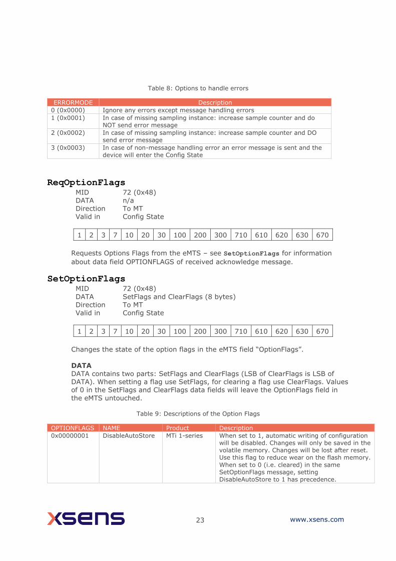
Table 8: Options to handle errors
ERRORMODE Description
0 (0x0000) Ignore any errors except message handling errors
1 (0x0001) In case of missing sampling instance: increase sample counter and do NOT send error message
2 (0x0002) In case of missing sampling instance: increase sample counter and DO send error message
3 (0x0003) In case of non-message handling error an error message is sent and the
device will enter the Config State
ReqOptionFlags MID 72 (0x48)
DATA n/a
Direction To MT
Valid in Config State
1 2 3 7 10 20 30 100 200 300 710 610 620 630 670
Requests Options Flags from the eMTS – see SetOptionFlags for information
about data field OPTIONFLAGS of received acknowledge message.
SetOptionFlags MID 72 (0x48)
DATA SetFlags and ClearFlags (8 bytes)
Direction To MT
Valid in Config State
1 2 3 7 10 20 30 100 200 300 710 610 620 630 670
Changes the state of the option flags in the eMTS field “OptionFlags”.
DATA
DATA contains two parts: SetFlags and ClearFlags (LSB of ClearFlags is LSB of
DATA). When setting a flag use SetFlags, for clearing a flag use ClearFlags. Values
of 0 in the SetFlags and ClearFlags data fields will leave the OptionFlags field in
the eMTS untouched.
Table 9: Descriptions of the Option Flags
OPTIONFLAGS NAME Product Description
0x00000001 DisableAutoStore MTi 1-series When set to 1, automatic writing of configuration will be disabled. Changes will only be saved in the volatile memory. Changes will be lost after reset. Use this flag to reduce wear on the flash memory.
When set to 0 (i.e. cleared) in the same
SetOptionFlags message, setting DisableAutoStore to 1 has precedence.

24 www.xsens.com
0x00000002 DisableAutoMeasurement
MTi 1-series When set to 1, the MT will stay in Config Mode upon start up. This allows full control on when the MT may start sending data. When set to 0 (i.e. cleared) in the same SetOptionFlags message, setting DisableAutoMeasurement to 1 has precedence.
0x00000004 EnableBeidou MTi-7 MTi-670 MTi-G-710
Enables Beidou, disables GLONASS.
0x00000008 Reserved
0x00000010 EnableAhs MTi 1-series
MTi 10-series MTi 100-series
When set to 1, the MTi will have Active Heading
Stabilization (AHS) enabled. AHS overrides magnetic reference, so heading output will be heading tracking instead of referenced heading. Note: AHS is enabled for the MTi-620 and MTi-630 by selecting the VRUAHS filter profile.
0x00000020 EnableOrientationSmoother
MTi-G-710 When set to 1, the MTi will have the Orientation Smoother enabled. The Orientation Smoother aims to reduce any sudden jumps in the Orientation outputs that arise when fusing low-rate GNSS messages with high-rate inertial data.
0x00000040 EnableConfigurabl
eBusId
MTi 10-series
MTi 100-series MTi 600-series
When set to 1, the MTi will use the BusId
configured in EMTS for all Xbus communication.
0x00000080 EnableInRunCompassCalibration
MTi 1-series MTi 10-series MTi 100-series
MTi 600-series
When set to 1, the MTi will have In-run Compass Calibration (ICC) enabled. ICC compensates for magnetic disturbances that move with the object.
0x00000200 EnableConfigMessageAtStartup
MTi 1-series When set to 1, the MTi will automatically send eMTS and Configuration messages at startup. This is a default feature for MTi 10-series, MTi 100-series and MTi 600-series devices.
Examples:
Setting the following message will set DisableAutoStore and will clear the
DisableAutoMeasurement flag:
Preamble, BusId, MID,
LEN
SetFlags (4
bytes)
ClearFlags (4
bytes)
Checksum
FA FF 48 08 00 00 00 01 00 00 00 02 CS
The result will be that changes made will not be written to the flash memory and
that the MT will go to Measurement Mode upon wake up.
Example → message for enabling AHS: FA FF 48 08 00 00 00 10 00 00 00 00 A1
ReqLocationID MID 132 (0x84)
DATA n/a
Direction To MT
Valid in Config State

25 www.xsens.com
1 2 3 7 10 20 30 100 200 300 710 610 620 630 670
Request location ID - see SetLocationID for information about data field of
received acknowledge message.
SetLocationID MID 132 (0x84)
DATA LOCID (2 bytes)
Direction To MT
Valid in Config State
1 2 3 7 10 20 30 100 200 300 710 610 620 630 670
Set a user-defined value. This value can be used to give the device a location
dependant identifier or any arbitrary user value.
LOCID
A 16 bit value having an arbitrary value set by the user. Default value is zero.
RestoreFactoryDef MID 14 (0x0E)
DATA n/a
Direction To MT
Valid in Config State
1 2 3 7 10 20 30 100 200 300 710 610 620 630 670
If this message is sent to the MT the factory defaults are restored. All settings
that have changed will be discarded including object alignments, filter settings,
etc. For more information about the default settings values see section 7.1.
ReqTransmitDelay MID 220 (0xDC)
DATA n/a
Direction To MT
Valid in Config State
10 20 30 100 200 300 710
Requests the delay value which equals the minimum time between last byte
reception and transmission start of acknowledge in RS485 mode.
SetTransmitDelay MID 220 (0xDC)
26 www.xsens.com
DATA Delay value (2 bytes)
Direction To MT
Valid in Config State
10 20 30 100 200 300 710
An unsigned 16 bit value that defines the number of clock ticks to delay the
transmission start after last byte reception. One clock tick is equal to 1 / 29.4912
MHz = 33.9ns. This setting has no effect on RS-232 type MTs.
Valid delay values are 590 (20 μs) to 65535 (2.2 ms).
5.3.4 Synchronization messages
ReqSyncSettings MID 44 (0x2C)
DATA None (0 bytes)
Valid in Config State
1 2 3 7 10 20 30 100 200 300 710 610 620 630 670
Request the synchronization settings of the device. This will return a full list of all
configured synchronization options. See SetSyncSettings for a description of the
fields in the message. The data size of the result will be N*12 bytes, where
N=[0..10].
SetSyncSettings MID 44 (0x2C)
DATA Setting List (N*12 bytes)
Valid in Config State
1 2 3 7 10 20 30 100 200 300 710 610 620 630 670
Set the synchronization settings of the device. This will replace the current
synchronization options with the supplied list.
The size of the message data part is used to compute the size of the list. Each
entry in the list is 12 bytes. To clear the list of sync settings, send a message with
a single entry with a polarity set to 0.
Settings
For information on the functionality, refer to [MTi_10s_100s], [MTi_600s] and
[MTi_1s]. Each setting describes either a system event that should trigger a sync
out action or a sync in event that should trigger a system action. The layout of the
fields is similar for both sync in and sync out settings, but the values are
interpreted slightly differently.

27 www.xsens.com
“Trigger Once” means that the device will perform the action only once. If the
device is reset or receives new sync settings it will again perform the action once.
Table 10: Sync in settings
Offset (bytes)
Setting Size (bytes)
Description
0 Function 1 The action to take when activated (see Table 12)
1 Line 1 The sync line to use (see Table 13)
2 Polarity 1 Which line transition to respond to. One of: Rising Edge (1), Falling Edge (2) or Both (3) If polarity is set to (0), the sync setting will be
disabled.
3 Trigger Once 1 Trigger only once (1) or multiple times (0).
4 Skip First 2 The number of initial events to skip before taking action.
6 Skip Factor 2 The number of events to skip after taking the action before taking action again. Ignored for ReqData.
8 Pulse Width 2 Ignored for sync in.
10 Delay or Clock period
2 Delay after receiving a sync pulse to taking action (100μs units, range [0..60000]) or
Reference clock period (in ms) for ClockBiasEstimation.
Table 11: Sync out settings
Offset (bytes)
Setting Size (bytes)
Description
0 Function 1 The system event to respond to (see Table 12)
1 Line 1 The sync line to use (see Table 13).
2 Polarity 1 The polarity of the sync pulse. One of: Positive Pulse (1), Negative Pulse (2), Both/Toggle (3).
If polarity is set to (0), the sync setting will be disabled.
3 Trigger Once 1 Trigger only once (1) or multiple times (0).
4 Skip First 2 The number of initial events to skip before
taking action.
6 Skip Factor 2 The number of events to skip after taking the action before taking action again.
8 Pulse Width 2 The width of the generated pulse in 100μs units.
Ignored for Toggle pulses.
10 Offset
2 Offset from event to pulse generation (100μs units, range [-30000..+30000]).
Table 12: Available sync functions
ID Name MTi-
1s
MTi-
7
MTi-
10s /
MTi-100s
MTi-
G-
710
MTi-
610
620 630
MTi-
670
Description
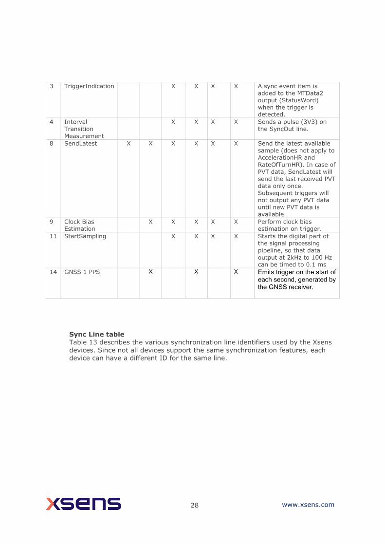
28 www.xsens.com
3 TriggerIndication X X X X A sync event item is added to the MTData2 output (StatusWord) when the trigger is detected.
4 Interval
Transition Measurement
X X X X Sends a pulse (3V3) on
the SyncOut line.
8 SendLatest X X X X X X Send the latest available
sample (does not apply to AccelerationHR and RateOfTurnHR). In case of
PVT data, SendLatest will send the last received PVT data only once. Subsequent triggers will not output any PVT data until new PVT data is
available.
9 Clock Bias Estimation
X X X X X Perform clock bias estimation on trigger.
11 StartSampling X X X X Starts the digital part of the signal processing
pipeline, so that data
output at 2kHz to 100 Hz can be timed to 0.1 ms
14 GNSS 1 PPS X X X Emits trigger on the start of each second, generated by the GNSS receiver.
Sync Line table
Table 13 describes the various synchronization line identifiers used by the Xsens
devices. Since not all devices support the same synchronization features, each
device can have a different ID for the same line.
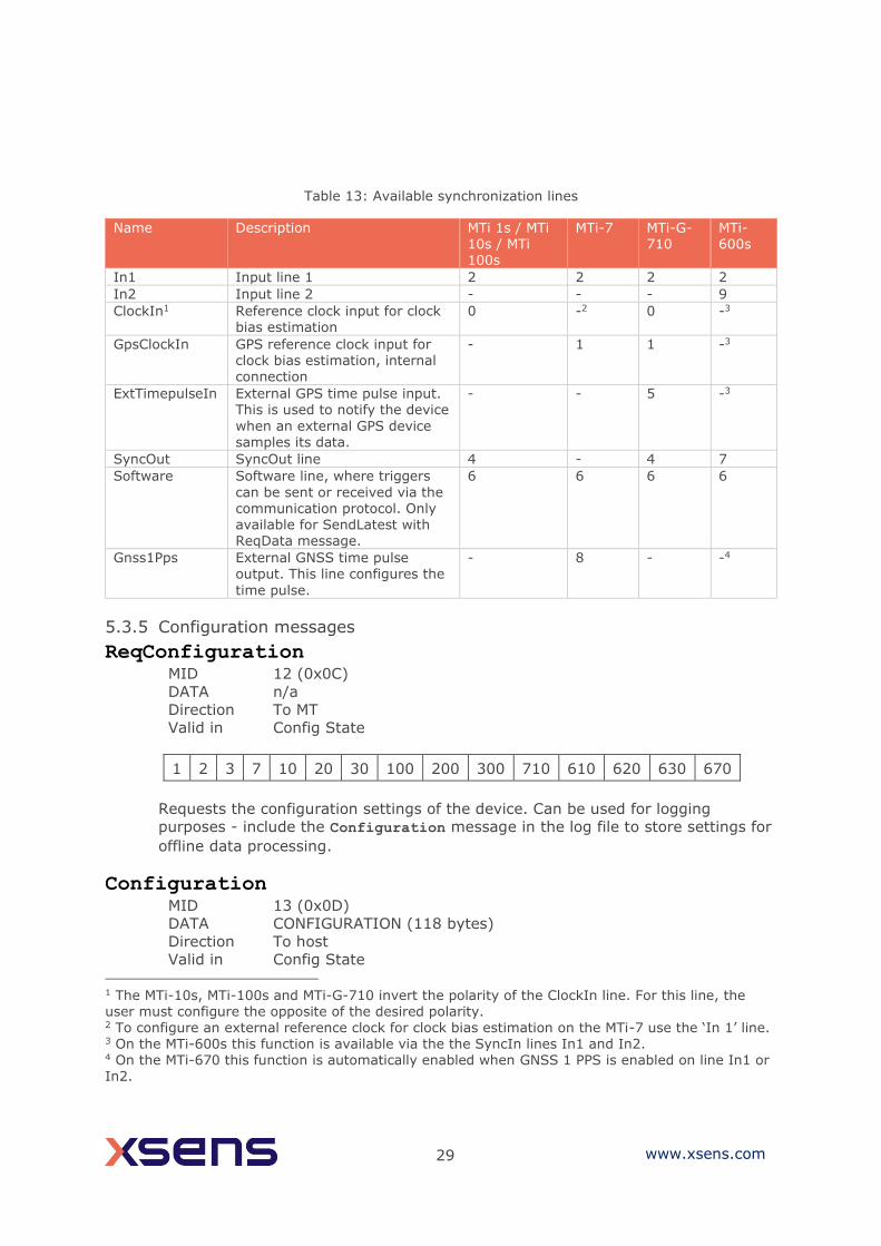
29 www.xsens.com
Table 13: Available synchronization lines
Name Description MTi 1s / MTi 10s / MTi 100s
MTi-7 MTi-G-710
MTi-600s
In1 Input line 1 2 2 2 2
In2 Input line 2 - - - 9
ClockIn1 Reference clock input for clock bias estimation
0 -2 0 -3
GpsClockIn GPS reference clock input for clock bias estimation, internal connection
- 1 1 -3
ExtTimepulseIn External GPS time pulse input. This is used to notify the device
when an external GPS device samples its data.
- - 5 -3
SyncOut SyncOut line 4 - 4 7
Software Software line, where triggers
can be sent or received via the communication protocol. Only available for SendLatest with ReqData message.
6 6 6 6
Gnss1Pps External GNSS time pulse output. This line configures the
time pulse.
- 8 - -4
5.3.5 Configuration messages
ReqConfiguration MID 12 (0x0C)
DATA n/a
Direction To MT
Valid in Config State
1 2 3 7 10 20 30 100 200 300 710 610 620 630 670
Requests the configuration settings of the device. Can be used for logging
purposes - include the Configuration message in the log file to store settings for
offline data processing.
Configuration MID 13 (0x0D)
DATA CONFIGURATION (118 bytes)
Direction To host
Valid in Config State
1 The MTi-10s, MTi-100s and MTi-G-710 invert the polarity of the ClockIn line. For this line, the user must configure the opposite of the desired polarity. 2 To configure an external reference clock for clock bias estimation on the MTi-7 use the ‘In 1’ line. 3 On the MTi-600s this function is available via the the SyncIn lines In1 and In2. 4 On the MTi-670 this function is automatically enabled when GNSS 1 PPS is enabled on line In1 or In2.

30 www.xsens.com
1 2 3 7 10 20 30 100 200 300 710
Acknowledge of ReqConfiguration. Data field contains the current MTi
configuration.
Table 14: The contents of the configuration message (CONFIGURATION)
offset (B) length (B) Description
0 4 Master device ID
4 2 Sampling period
6 2 Output skip factor
8 2 Syncin settings - Mode
10 2 Syncin settings - Skip Factor
12 4 Syncin settings - Offset
16 8 Date, format YYYYMMDD (can be set by host)
24 8 Time, format HHMMSSHH (can be set by host)
32 32 Reserved (host)
64 32 Reserved (client)
96 2 Number of devices ( = 1 (0x0001))
98 4 Device ID (same as master device ID)
102 2 Data length of MTData2 message
104 2 Output mode
106 4 Output settings
110 8 Reserved
610 620 630 670
Acknowledge of ReqConfiguration. Data field contains the current MTi
configuration.
Table 15: The contents of the configuration message (CONFIGURATION) for MTi-600s
offset (B)
length (B)
Description
0 8 Master device ID (64-bit)
8 2 Syncin settings - Mode
10 2 Syncin settings - Skip Factor
12 4 Syncin settings - Offset
16 8 Date, format YYYYMMDD (can be set by host)
24 8 Time, format HHMMSSHH (can be set by host)
32 32 Reserved (host)
64 32 Reserved (client)
96 2 Number of devices ( = 1 (0x0001))
98 8 Device ID (same as master device ID)
102 12 Reserved
31 www.xsens.com
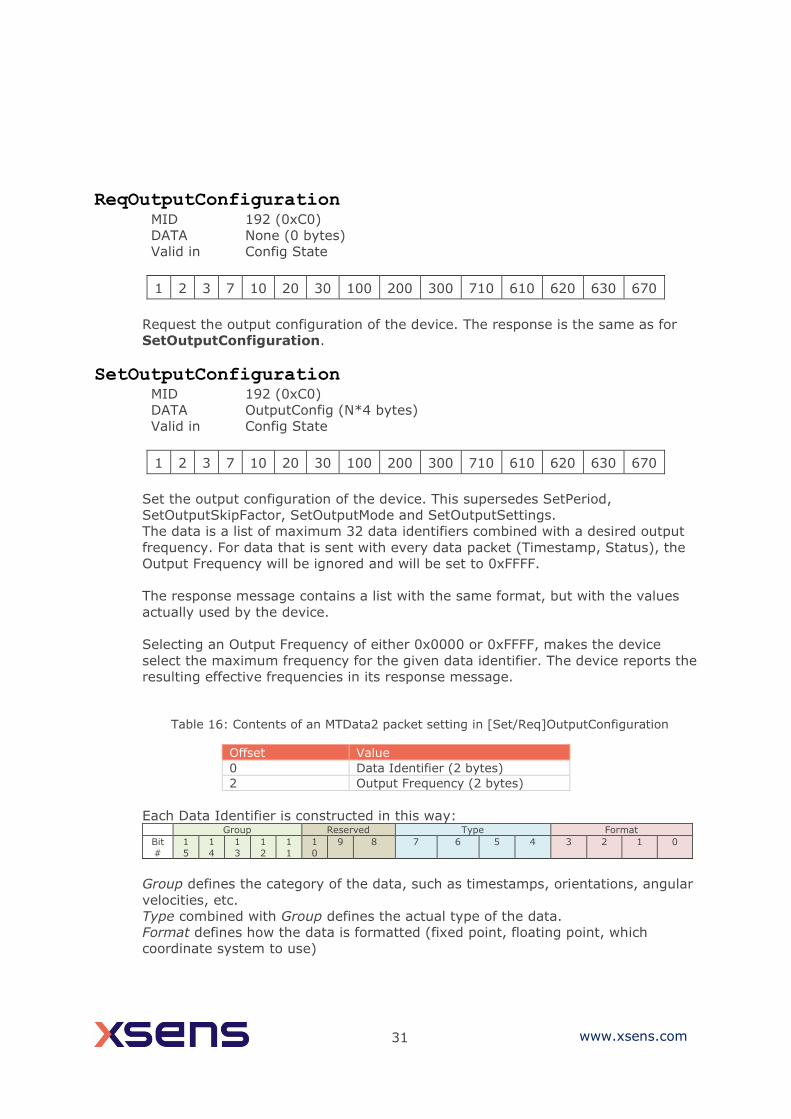
ReqOutputConfiguration MID 192 (0xC0)
DATA None (0 bytes)
Valid in Config State
1 2 3 7 10 20 30 100 200 300 710 610 620 630 670
Request the output configuration of the device. The response is the same as for
SetOutputConfiguration.
SetOutputConfiguration MID 192 (0xC0)
DATA OutputConfig (N*4 bytes)
Valid in Config State
1 2 3 7 10 20 30 100 200 300 710 610 620 630 670
Set the output configuration of the device. This supersedes SetPeriod,
SetOutputSkipFactor, SetOutputMode and SetOutputSettings.
The data is a list of maximum 32 data identifiers combined with a desired output
frequency. For data that is sent with every data packet (Timestamp, Status), the
Output Frequency will be ignored and will be set to 0xFFFF.
The response message contains a list with the same format, but with the values
actually used by the device.
Selecting an Output Frequency of either 0x0000 or 0xFFFF, makes the device
select the maximum frequency for the given data identifier. The device reports the
resulting effective frequencies in its response message.
Table 16: Contents of an MTData2 packet setting in [Set/Req]OutputConfiguration
Offset Value
0 Data Identifier (2 bytes)
2 Output Frequency (2 bytes)
Each Data Identifier is constructed in this way: Group Reserved Type Format
Bit
#
1
5
1
4
1
3
1
2
1
1
1
0
9 8 7 6 5 4 3 2 1 0
Group defines the category of the data, such as timestamps, orientations, angular
velocities, etc.
Type combined with Group defines the actual type of the data.
Format defines how the data is formatted (fixed point, floating point, which
coordinate system to use)

32 www.xsens.com
Reserved is currently unused, but reserved for adding new options to Group and
Type.
All current identifiers are listed in the MT SDK 4 in xsdataidentifiers.h and are
listed in the table below. For a description of their contents, refer to the MTData2
message description in section 5.3.6.
33 www.xsens.com
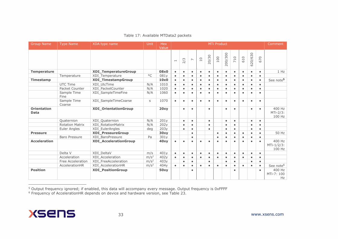
Table 17: Available MTData2 packets
Group Name Type Name XDA type name Unit Hex Value
MTi Product Comment
1
2/3
7
10
20/3
0
100
200/3
00
710
610
620/6
30
670
Temperature XDI_TemperatureGroup 08x0 ● ● ● ● ● ● ● ● ● ● ● 1 Hz
Temperature XDI_Temperature °C 081y ● ● ● ● ● ● ● ● ● ● ●
Timestamp XDI_TimestampGroup 10x0 ● ● ● ● ● ● ● ● ● ● ● See note5
UTC Time XDI_UtcTime N/A 1010 ● ● ● ● ● ● ● ● ● ● ●
Packet Counter XDI_PacketCounter N/A 1020 ● ● ● ● ● ● ● ● ● ● ●
Sample Time Fine
XDI_SampleTimeFine N/A 1060 ● ● ● ● ● ● ● ● ● ● ●
Sample Time Coarse
XDI_SampleTimeCoarse s 1070 ● ● ● ● ● ● ● ● ● ● ●
Orientation Data
XDI_OrientationGroup 20xy ● ● ● ● ● ● ● 400 Hz MTi-2/3:
100 Hz
Quaternion XDI_Quaternion N/A 201y ● ● ● ● ● ● ●
Rotation Matrix XDI_RotationMatrix N/A 202y ● ● ● ● ● ● ●
Euler Angles XDI_EulerAngles deg 203y ● ● ● ● ● ● ●
Pressure XDI_PressureGroup 30xy ● ● ● ● ● ● ● 50 Hz
Baro Pressure XDI_BaroPressure Pa 301y ● ● ● ● ● ● ●
Acceleration XDI_AccelerationGroup 40xy ● ● ● ● ● ● ● ● ● ● ● 400 Hz MTi-1/2/3:
100 Hz
Delta V XDI_DeltaV m/s 401y ● ● ● ● ● ● ● ● ● ● ●
Acceleration XDI_Acceleration m/s2 402y ● ● ● ● ● ● ● ● ● ● ●
Free Acceleration XDI_FreeAcceleration m/s2 403y ● ● ● ● ● ● ●
AccelerationHR XDI_AccelerationHR m/s2 404y ● ● ● ● ● ● ● ● ● ● ● See note6
Position XDI_PositionGroup 50xy ● ● ● 400 Hz MTi-7: 100
Hz
5 Output frequency ignored; if enabled, this data will accompany every message. Output frequency is 0xFFFF 6 Frequency of AccelerationHR depends on device and hardware version, see Table 23.
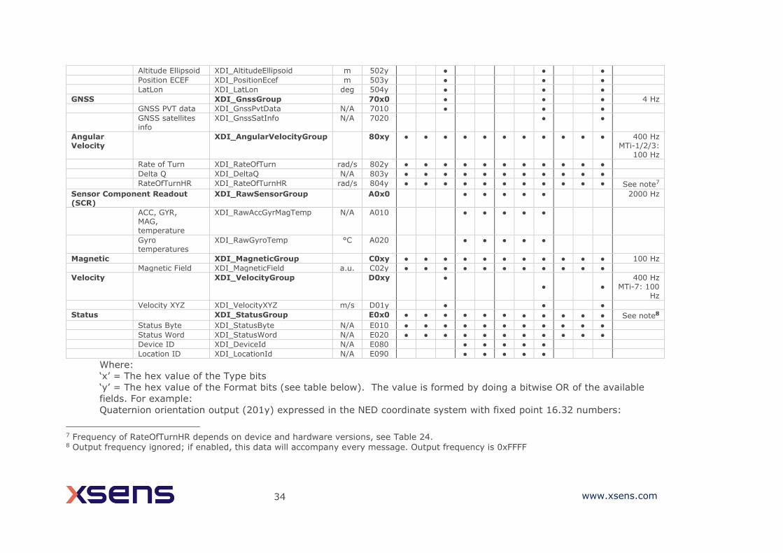
34 www.xsens.com
Altitude Ellipsoid XDI_AltitudeEllipsoid m 502y ● ● ●
Position ECEF XDI_PositionEcef m 503y ● ● ●
LatLon XDI_LatLon deg 504y ● ● ●
GNSS XDI_GnssGroup 70x0 ● ● ● 4 Hz
GNSS PVT data XDI_GnssPvtData N/A 7010 ● ● ●
GNSS satellites info
XDI_GnssSatInfo N/A 7020 ● ●
Angular Velocity
XDI_AngularVelocityGroup 80xy ● ● ● ● ● ● ● ● ● ● ● 400 Hz MTi-1/2/3:
100 Hz
Rate of Turn XDI_RateOfTurn rad/s 802y ● ● ● ● ● ● ● ● ● ● ●
Delta Q XDI_DeltaQ N/A 803y ● ● ● ● ● ● ● ● ● ● ●
RateOfTurnHR XDI_RateOfTurnHR rad/s 804y ● ● ● ● ● ● ● ● ● ● ● See note7
Sensor Component Readout (SCR)
XDI_RawSensorGroup A0x0 ● ● ● ● ● 2000 Hz
ACC, GYR, MAG, temperature
XDI_RawAccGyrMagTemp N/A A010 ● ● ● ● ●
Gyro temperatures
XDI_RawGyroTemp °C A020 ● ● ● ● ●
Magnetic XDI_MagneticGroup C0xy ● ● ● ● ● ● ● ● ● ● ● 100 Hz
Magnetic Field XDI_MagneticField a.u. C02y ● ● ● ● ● ● ● ● ● ● ●
Velocity XDI_VelocityGroup D0xy ● ● ●
400 Hz MTi-7: 100
Hz
Velocity XYZ XDI_VelocityXYZ m/s D01y ● ● ●
Status XDI_StatusGroup E0x0 ● ● ● ● ● ● ● ● ● ● ● See note8
Status Byte XDI_StatusByte N/A E010 ● ● ● ● ● ● ● ● ● ● ●
Status Word XDI_StatusWord N/A E020 ● ● ● ● ● ● ● ● ● ● ●
Device ID XDI_DeviceId N/A E080 ● ● ● ● ●
Location ID XDI_LocationId N/A E090 ● ● ● ● ●
Where:
‘x’ = The hex value of the Type bits
‘y’ = The hex value of the Format bits (see table below). The value is formed by doing a bitwise OR of the available
fields. For example:
Quaternion orientation output (201y) expressed in the NED coordinate system with fixed point 16.32 numbers:
7 Frequency of RateOfTurnHR depends on device and hardware versions, see Table 24. 8 Output frequency ignored; if enabled, this data will accompany every message. Output frequency is 0xFFFF
35 www.xsens.com
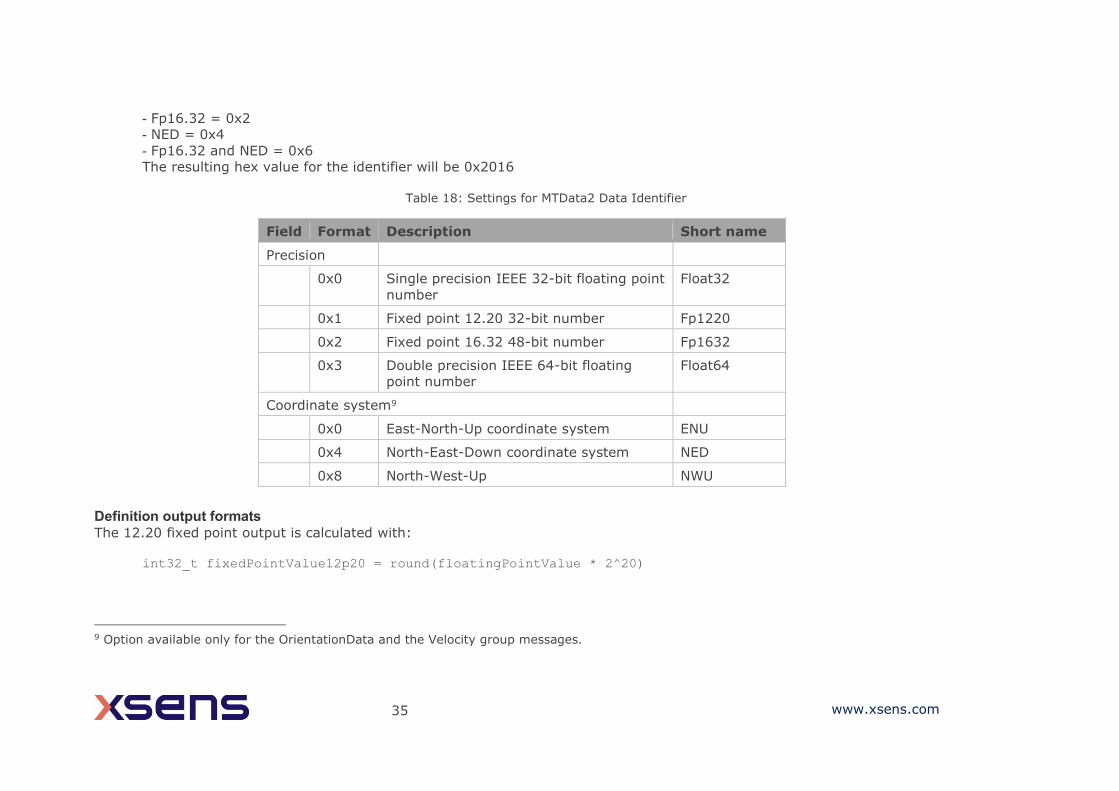
- Fp16.32 = 0x2
- NED = 0x4
- Fp16.32 and NED = 0x6
The resulting hex value for the identifier will be 0x2016
Table 18: Settings for MTData2 Data Identifier
Field Format Description Short name
Precision
0x0 Single precision IEEE 32-bit floating point
number
Float32
0x1 Fixed point 12.20 32-bit number Fp1220
0x2 Fixed point 16.32 48-bit number Fp1632
0x3 Double precision IEEE 64-bit floating
point number
Float64
Coordinate system9
0x0 East-North-Up coordinate system ENU
0x4 North-East-Down coordinate system NED
0x8 North-West-Up NWU
Definition output formats The 12.20 fixed point output is calculated with:
int32_t fixedPointValue12p20 = round(floatingPointValue * 2^20)
9 Option available only for the OrientationData and the Velocity group messages.
36 www.xsens.com
The resulting 32bit integer value is transmitted in big-endian order (MSB first). The range of a 12.20 fixed point value is [-
2048.0 .. 2047.9999990]
The 16.32 fixed point output is calculated with:
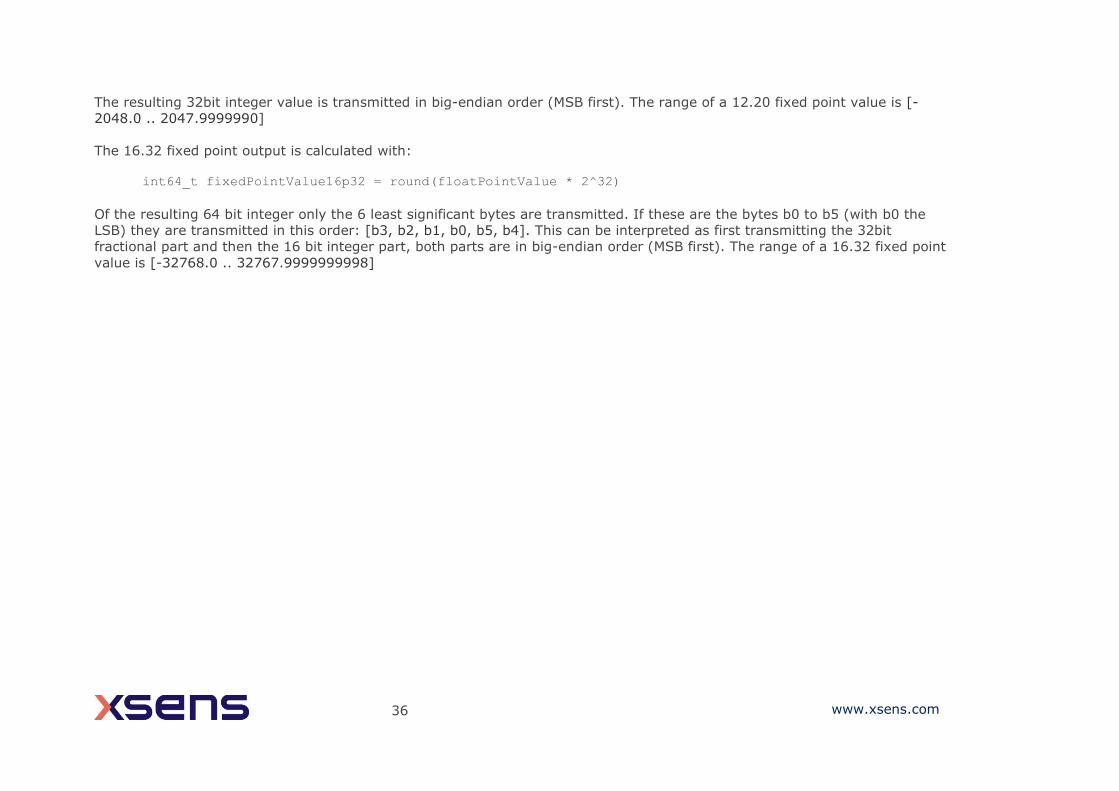
int64_t fixedPointValue16p32 = round(floatPointValue * 2^32)
Of the resulting 64 bit integer only the 6 least significant bytes are transmitted. If these are the bytes b0 to b5 (with b0 the
LSB) they are transmitted in this order: [b3, b2, b1, b0, b5, b4]. This can be interpreted as first transmitting the 32bit
fractional part and then the 16 bit integer part, both parts are in big-endian order (MSB first). The range of a 16.32 fixed point
value is [-32768.0 .. 32767.9999999998]
1 www.xsens.com
ReqStringOutputType MID 142 (0x8E)
DATA n/a
Direction To MT
Valid in Config State
10 20 30 100 200 300 700 710 610 620 630 670
Request the configuration of the NMEA data output.
For the 10, 20, 30, 100, 200, 300, 700 and 710, the frequency can be retrieved
with ReqPeriod message. For the 610, 620, 630 and 670 the frequency is stored
together with the string type.
SetStringOutputType MID 142 (0x8E)
DATA NMEA strings
Direction To MT
Valid in Config State
10 20 30 100 200 300 700 710 610 620 630 670
Configures the NMEA data output. The format for this message is as follows:
For the 10, 20, 30, 100, 200, 300, 700, 710:
uint16_t stringType
The frequency must be set with SetPeriod.
For the 610, 620, 630 and 670:
uint32_t stringType
uint16_t frequency
NMEA strings are not part of the XBus protocol, and do not have the message structure
of the XBus protocol. The following strings are available:
Bit String Type Summary
Format
Description
0 $HCHDM Magnetic Heading $HCHDM,xxx.xx,M*hh
xxx.xx → heading with decimal fraction
M → Magnetic

2 www.xsens.com
*hh → checksum
1 $HCHDG Heading with HeadingOffset $HCHDG,x.x,y.y,a,z.z,a*hr x.x → magnetic sensor heading
y.y → magnetic deviation a → positive/negative deviation/variation z.z → magnetic variation in degrees a → positive/negative deviation/variation
*hr → checksum
2 TSS2 Note: This is a binary output. Heading, Heave (0), Status, Roll, Pitch, Heading Status flag (F) :DDDDDSMHHHHQMRRRRSMPPPPE
DDDDD → Heading * 100 degrees S → space M → space if positive, minus if negative HHHH → Heave in centimetres (fixed to 0) Q → Status flag (fixed to H, Heading)
M → space if positive, minus if negative RRRR → Roll * 100 degrees S → Space M → space of positive, minus if negative
PPPP → Pitch * 100 degrees E → Heading status flag, fixed to F
3 $PHTRO Pitch, Roll $PHTRO,x.xx,a,y.yy,b*hh
x.xx → pitch in degrees a → ‘M’ for bow up, ‘P’ for bow down y.yy → roll in degrees b→ port down
*hh → terminator and checksum
4 $PRDID Pitch, Roll, Heading $PRDID,PPP.PP,RRR.RR,hhh.hh PPP.PP → Pitch in degrees
RRR.RR → Roll in degrees hhh.hh →True Heading in degrees
5 EM1000 Note: This is a binary output.
Roll, Pitch, Heave (0), Heading ABRRPPAAHH AB → header 0x 00 90 RR → Roll in 0.01 degrees PP → Pitch in 0.01 degrees
AA → Heave in cm (fixed to 0) HH → Heading in 0.01 degrees
6 $PSONCMS Quaternion, Acceleration, Rate of Turn, Magnetic Field, Temperature $PSONCMS,Q.QQQQ,P.PPPP,R.RRRR,S.SSSS,XX.XXXX,YY.YYYY,ZZ.ZZZZ,
FF.FFFF,GG.GGGG,HH.HHHH,NN.NNNN,MM,MMMM,PP.PPPP,TT.T*hh
3 www.xsens.com
Q.QQQQ → q0 from quaternions P.PPPP → q1 from quaternions R.RRRR → q2 from quaternions S.SSSS → q3 from quaternions XX.XXXX → acceleration X in m/s2
YY.YYYY → acceleration Y in m/s2
ZZ.ZZZZ → acceleration Z in m/s2
FF.FFFF → rate of turn X in rad/s GG.GGGG → rate of turn Y in rad/s
HH.HHHH → rate of turn Z in rad/s NN.NNNN → magnetic field X in a.u. MM.MMMM → magnetic field Y in a.u. PP.PPPP → magnetic field Z in a.u. TT.T → Sensor temperature in degrees Celsius
*hh → checksum
7 $HCMTW Temperature $HCMTW,TT.T,C*hh TT.T → Sensor temperature in degrees Celsius
C → indicates degrees Celsius *hh → checksum
8 $HEHDT True Heading $HEHDT,xxx.xx,T*hh
xxx.xx → Heading in degrees T → heading type (True, Grid, Magnetic)
9 $HEROT Rate of Turn
$HEROT,-xxx.x,A*hh -xxx.x → rate of turn Z in deg/min (- means bow turns to port) A → data valid *hh → checksum
10 $GPGGA $GPGGA,hhmmss.ss,llll.llll,a,yyyyy.yyyy,a,x,xx,x.x,x.x,M,x.x,M,x.x,xxxx*hh hhmmss.ss → UTC time llll.llll → Latitude a → North or South
yyyyy.yyyy → Longitude
a → East or West x → GPS quality indicator (0=invalid; 1=GPS fix; 2=Diff. GPS fix) xx → number of satellites in view
x.x → HDOP x.x → Height above sea level (MSL) M → meters x.x → Geoidal separation between height above MSL and geoid (WGS84) M → meters
x.x → age in seconds since last update from DGPS station (not used, blank) xxxx → DGPS station reference ID# (not used, blank) *hh → checksum
11 $PTCF $PTCF,hhh.h,T,+RRR.R,+PPP.P,+rrr.r,+ppp.p*cs
hhh.h → heading
T → True North +RRR.R → roll
4 www.xsens.com
+PPP.P → pitch +rrr.r → roll rate +ppp.p → pitch rate *cs → checksum
12 $XSVEL $XSVEL,+xxx.xxxx,+yyy.yyyy,+zzz.zzzz*cs xxx.xxxx → Velocity X yyy.yyyy → Velocity Y zzz.zzzz → Velocity Z
13 $GPZDA $GPZDA,hhmmss.ss,dd,mm,yyyy,xx,yy*CC hhmmss → Hours Minutes Seconds (UTC) dd,mm,yyy → Day,Month,Year xx → 00
yy → 00 *CC checksum
14 $GPRMC $GPRMC,hhmmss,a,llll.ll,a,yyyy.yy,a,sss.s,ccc.c,ddmmyy,vvv.v,a,*cs
hhmmss → Hours Minutes Seconds (UTC of position) a → Validity – A-ok, V-invalid llll.ll → Latitude (DDmm.mm) a → North or South yyyy.yy → Longitude (DDDmm.mm)
a → East or West
sss.s → Speed over ground in knots ccc.c → True course ddmmyy → Date (Day Month Year)
vvv.v → Magnetic variation a → Magnetic variation direction (East or West) *cs → Checksum
15 Reserved Reserved for future string types
ReqPeriod MID 4 (0x04)
DATA n/a
Direction To MT
Valid in Config State
10 20 30 100 200 300 710
Request the current sample period. The MT replies with ReqPeriodAck. The data
field of this message contains the sample period. For the description of the data
field see SetPeriod. Note: ReqPeriod for MTi MkIV (MTi 10-710) is only available
for NMEA output mode (SetStringOutputType).
SetPeriod MID 4 (0x04)
DATA PERIOD (2 bytes)
Direction To MT
Valid in Config State
5 www.xsens.com
10 20 30 100 200 300 710
Sets the sampling period of the device used in Measurement State. Note:
SetPeriod for MTi MkIV (MTi 10-710) is only available for NMEA output mode
(SetStringOutputType).
PERIOD
PERIOD is an unsigned 16-bit value indicating the length of the period. Resolution
is in (1/115200) seconds, i.e. 8.68 us. The following table shows the default,
minimum and maximum values.
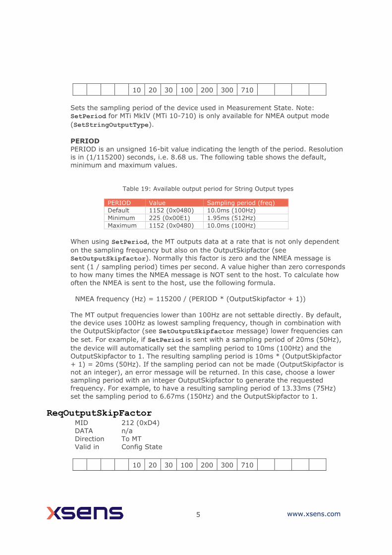
Table 19: Available output period for String Output types
PERIOD Value Sampling period (freq)
Default 1152 (0x0480) 10.0ms (100Hz)
Minimum 225 (0x00E1) 1.95ms (512Hz)
Maximum 1152 (0x0480) 10.0ms (100Hz)
When using SetPeriod, the MT outputs data at a rate that is not only dependent
on the sampling frequency but also on the OutputSkipfactor (see
SetOutputSkipfactor). Normally this factor is zero and the NMEA message is
sent (1 / sampling period) times per second. A value higher than zero corresponds
to how many times the NMEA message is NOT sent to the host. To calculate how
often the NMEA is sent to the host, use the following formula.
NMEA frequency (Hz) = 115200 / (PERIOD * (OutputSkipfactor + 1))
The MT output frequencies lower than 100Hz are not settable directly. By default,
the device uses 100Hz as lowest sampling frequency, though in combination with
the OutputSkipfactor (see SetOutputSkipfactor message) lower frequencies can
be set. For example, if SetPeriod is sent with a sampling period of 20ms (50Hz),
the device will automatically set the sampling period to 10ms (100Hz) and the
OutputSkipfactor to 1. The resulting sampling period is 10ms * (OutputSkipfactor
+ 1) = 20ms (50Hz). If the sampling period can not be made (OutputSkipfactor is
not an integer), an error message will be returned. In this case, choose a lower
sampling period with an integer OutputSkipfactor to generate the requested
frequency. For example, to have a resulting sampling period of 13.33ms (75Hz)
set the sampling period to 6.67ms (150Hz) and the OutputSkipfactor to 1.
ReqOutputSkipFactor MID 212 (0xD4)
DATA n/a
Direction To MT
Valid in Config State
10 20 30 100 200 300 710
6 www.xsens.com
Request how many times the data output is skipped before sending the data in
the NMEA message to host. For information about data field of received
acknowledge see SetOutputSkipFactor. Note: ReqOutputSkipFactor for MTi
MkIV (MTi 10-710) is only available for NMEA output mode
(SetStringOutputType).
SetOutputSkipfactor MID 212 (0xD4)
DATA SKIPFACTOR (2 bytes)
Direction To MT
Valid in Config State
10 20 30 100 200 300 710
Set the output skip factor.
SKIPFACTOR
The skip factor is an unsigned 16 bit value and is by default zero. The value
represents how many times the data output is skipped (running at the current
sampling frequency) before the next NMEA message is sent, i.e. at sample period
of 5.0ms (200Hz) and a skip factor of 4, the measurement is running at 200Hz
but the data is sent at a rate of 40Hz (not 50Hz). See also SetPeriod for more
information about the relationship between the sampling period and output skip
factor. Note: SetOutputSkipFactor for MTi MkIV (MTi 10-710) is only available
for NMEA output mode (SetStringOutputType).
If SKIPFACTOR is set to 65535 (0xFFFF), no data will be sent to the host and
ReqData can be use to request an NMEA message at an arbitrary time. This works
also if SyncIn mode is enabled. Table 20: Use of Output Skipfactor with String Outputs
SKIPFACTOR Description
≠ 65535 (0xFFFF) Skipfactor value
65535 (0xFFFF) Do not send NMEA data automatically
ReqAlignmentRotation MID 236 (0xEC)
DATA PARAMETER (1 byte)
Direction To MT
Valid in Config State
1 2 3 7 10 20 30 100 200 300 710 610 620 630 670
Request the internally stored object alignments (RotSensor and RotLocal in
quaternions) which are set by the ResetOrientation message or
SetAlignmentRotation message. For information about data field of received
acknowledge see SetAlignmentRotation.

7 www.xsens.com
SetAlignmentRotation MID 236 (0xEC)
DATA PARAMETER + QUATERNION (4x4 bytes)
Direction To MT
Valid in Config State
1 2 3 7 10 20 30 100 200 300 710 610 620 630 670
Set the object alignment.
PARAMETER
The parameter indicates which alignment rotation will be set.
Table 21: List of alignment matrices designations
PARAMETER value Description
0 Sensor alignment (RotSensor)
1 Local alignment (RotLocal)
QUATERNION
Corresponds to the alignment matrices RotSensor and RotLocal. The quaternion
(to be entered in floats) can be found by applying the matrix-to-quaternion
transformations as described in [MTi_10s_100s] or by using the functions in XDA.
Values 1-4 of the Quaternion field are displayed below.
q0 q1 q2 q3
Output Format: Float (DEFAULT)
The default format used by the MT is FLOAT. FLOAT is 4 bytes long and
corresponds with the single-precision floating-point value as defined in the IEEE
754 standard (= float)
ReqExtOutputMode MID 134 (0x86)
DATA MODE (2 bytes)
Direction To MT
Valid in Config State
10 20 30 100 200 300 710
Requests the current Extended Output Mode. See SetExtOutputMode for
information about the data field of the received acknowledge message.
SetExtOutputMode MID 134 (0x86)
8 www.xsens.com
DATA MODE (2 bytes)
Direction To MT
Valid in Config State
10 20 30 100 200 300 710
Sets the Extended Output Mode. This message can be used to set the hardware
communication line to the alternative UART (see [MTi_10s_100s] for more
information on this feature). Table 22: Settings of Extended Output Mode
Extended Output Mode Description
Bit 3-0 Reserved
Bit 4 Alternative UART 0: Communication via serial connection and/or USB 1: Communication via alternative UART and/or USB
Bit 5 Enable USB low latency Mode 0: USB low latency disabled 1: USB low latency enabled
Bit 15-6 Reserved
Req/Set PortConfig MID 140 (0x8C)
Direction To MT
Valid in Config state
610 620 630 670
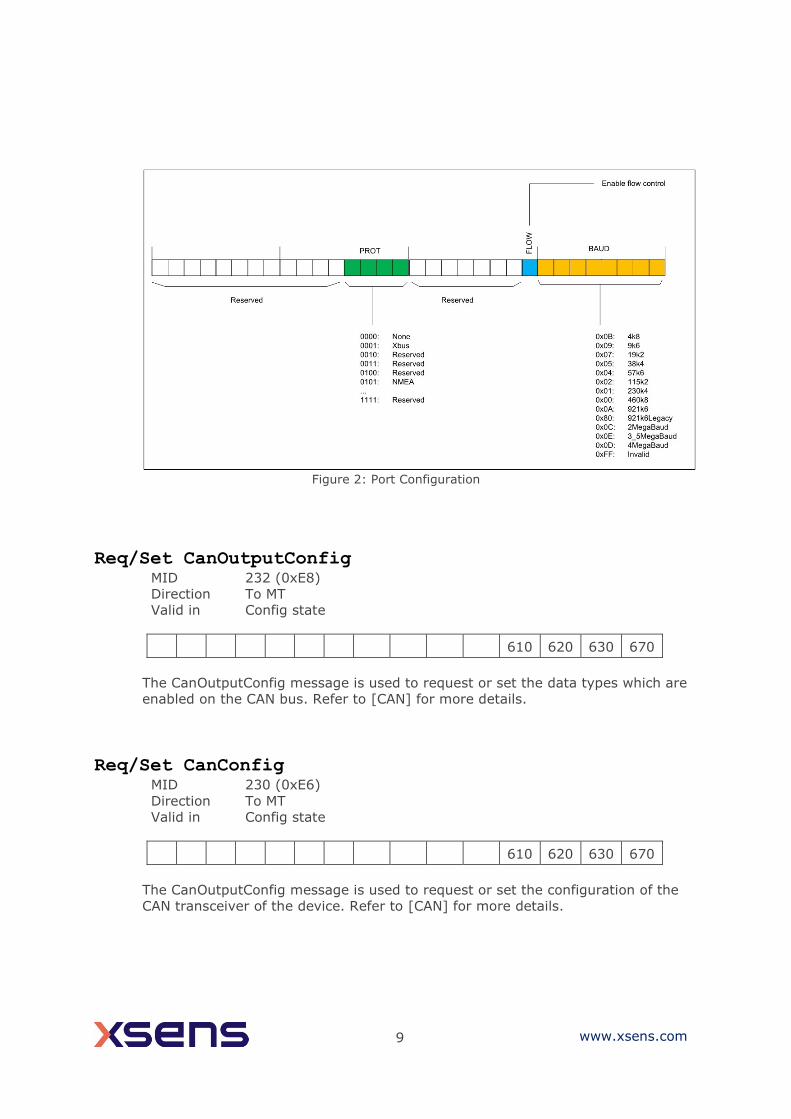
When the payload size is zero, this message is used to request the port
configuration from the device. When the payload size is nonzero, this message is
used to set the port configuration of the device. The port configuration exists of a
list of 32-bit words (see Figure 2), each describing the configuration of a port. The
MTi 600-series has two serial ports as described in [MTi_600s].
9 www.xsens.com
Figure 2: Port Configuration
Req/Set CanOutputConfig MID 232 (0xE8)
Direction To MT
Valid in Config state
610 620 630 670
The CanOutputConfig message is used to request or set the data types which are
enabled on the CAN bus. Refer to [CAN] for more details.
Req/Set CanConfig MID 230 (0xE6)
Direction To MT
Valid in Config state
610 620 630 670
The CanOutputConfig message is used to request or set the configuration of the
CAN transceiver of the device. Refer to [CAN] for more details.
10 www.xsens.com
5.3.6 Data-related messages
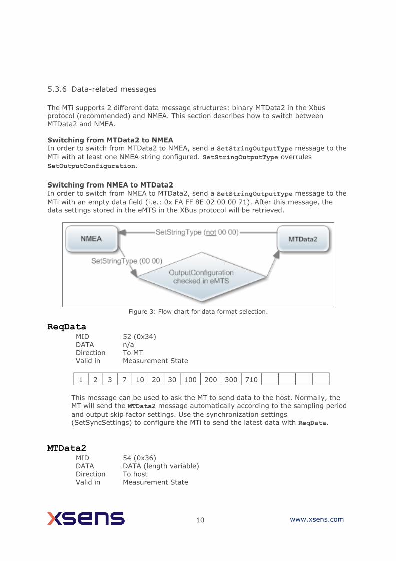
The MTi supports 2 different data message structures: binary MTData2 in the Xbus
protocol (recommended) and NMEA. This section describes how to switch between
MTData2 and NMEA.
Switching from MTData2 to NMEA
In order to switch from MTData2 to NMEA, send a SetStringOutputType message to the
MTi with at least one NMEA string configured. SetStringOutputType overrules
SetOutputConfiguration.
Switching from NMEA to MTData2
In order to switch from NMEA to MTData2, send a SetStringOutputType message to the
MTi with an empty data field (i.e.: 0x FA FF 8E 02 00 00 71). After this message, the
data settings stored in the eMTS in the XBus protocol will be retrieved.
Figure 3: Flow chart for data format selection.
ReqData MID 52 (0x34)
DATA n/a
Direction To MT
Valid in Measurement State
1 2 3 7 10 20 30 100 200 300 710
This message can be used to ask the MT to send data to the host. Normally, the
MT will send the MTData2 message automatically according to the sampling period
and output skip factor settings. Use the synchronization settings
(SetSyncSettings) to configure the MTi to send the latest data with ReqData.
MTData2 MID 54 (0x36)
DATA DATA (length variable)
Direction To host
Valid in Measurement State
11 www.xsens.com
1 2 3 7 10 20 30 100 200 300 710
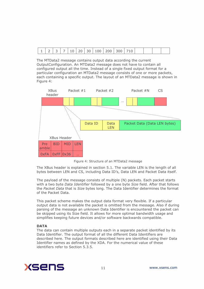
The MTData2 message contains output data according the current
OutputConfiguration. An MTData2 message does not have to contain all
configured output all the time. Instead of a single fixed output format for a
particular configuration an MTData2 message consists of one or more packets,
each containing a specific output. The layout of an MTData2 message is shown in
Figure 4:
XBus
header
Packet #1 Packet #2 Packet #N CS
…
Data ID Data
LEN
Packet Data (Data LEN bytes)
XBus Header
Pre
amble
BID MID LEN
0xFA 0xFF 0x36 ..
The XBus header is explained in section 5.1. The variable LEN is the length of all
bytes between LEN and CS, including Data ID’s, Data LEN and Packet Data itself.
The payload of the message consists of multiple (N) packets. Each packet starts
with a two byte Data Identifier followed by a one byte Size field. After that follows
the Packet Data that is Size bytes long. The Data Identifier determines the format
of the Packet Data.
This packet scheme makes the output data format very flexible. If a particular
output data is not available the packet is omitted from the message. Also if during
parsing of the message an unknown Data Identifier is encountered the packet can
be skipped using its Size field. It allows for more optimal bandwidth usage and
simplifies keeping future devices and/or software backwards compatible.
DATA
The data can contain multiple outputs each in a separate packet identified by its
Data Identifier. The output format of all the different Data Identifiers are
described here. The output formats described here are identified using their Data
Identifier names as defined by the XDA. For the numerical value of these
identifiers refer to Section 5.3.5.
Figure 4: Structure of an MTData2 message
12 www.xsens.com
In the following, format descriptions for data values are defined as [name : type].
In cases where the type is ℝ the data value is a real number and its format is
defined by the precision field of the data identifier (see Section 5.3.5). Normally,
the precision is set to 0x0 (Float32) which corresponds to the 4 bytes long single-
precision floating point value as defined in the IEEE 754 standard
Other defined types are:
U1: Unsigned Char.
U2: Unsigned 16-bit integer
U4: Unsigned 32-bit integer
I1: Two’s complement 8-bit integer.
I2: Two’s complement 16-bit integer.
I4: Two’s complement 32-bit integer.
Note: Not all outputs are available for all products. Refer to
SetOutputConfiguration for supported outputs per product.
XDI_Temperature
Contains the internal temperature of the sensor in degrees Celsius
XDI_UtcTime
Contains the timestamp expressed as the UTC time
XDI_PacketCounter
This packet contains the packet counter. This counter is incremented with every
generated MTData2 message
XDI_SampleTimeFine
Contains the sample time of an output expressed in 10 kHz clock ticks. When
there is no GNSS-fix, this value is arbitrary for GNSS messages.
This outputs wraps around at 0xFFFFFFFFF for the MTi 1-series and exactly after
one day (864000000 ticks) for the MTi 10-series and MTi 100-series.
XDI_SampleTimeCoarse
Contains the sample time of an output expressed in seconds. When there is no
GNSS-fix, this value is arbitrary for GNSS messages.
Temp : ℝ
ns : U4 Year : U2 Month : U1 Day : U1
Hour : U1 Minute : U1 Second : U1 Flags : U1
PacketCounter : U2
SampleTimeFine : U4
SampleTimeCoarse : U4
13 www.xsens.com
Combining XDI_SampleTimeCoarse and XDI_SampleTimeFine allows for creating
a big range timestamp (expressed as a real number) using:
BigTimestamp = [SampleTimeCoarse + (SampleTimeFine mod 10000) / 10000]
(seconds)For MTi 1-series devices, this computation is valid only until the
wraparound of XDI_SampleTimeFine occurs.
XDI_Quaternion
Contains orientation output expressed as a quaternion
XDI_EulerAngles
Contains the three Euler angles in degrees that represent the orientation of the
MT
XDI_RotationMatrix
This packet contains the rotation matrix (DCM) that represents the orientation of
the MT.
XDI_BaroPressure
Contains the pressure as measured by the internal barometer expressed in Pascal.
XDI_DeltaV
Contains the delta velocity value of the SDI output in m/s.
XDI_DeltaQ
Contains the delta quaternion value of the SDI output.
XDI_Acceleration
Contains the calibrated acceleration vector in x, y, and z axes in m/s2.
XDI_FreeAcceleration
Contains the free acceleration vector in x, y, and z axes in m/s2.
Q0 : ℝ Q1 : ℝ Q2 : ℝ Q3 : ℝ
Roll : ℝ Pitch : ℝ Yaw : ℝ
a : ℝ b : ℝ c : ℝ d : ℝ e : ℝ f : ℝ g : ℝ h : ℝ i : ℝ
Pressure : U4
Δv.x : ℝ Δv.y : ℝ Δv.z : ℝ
Δq0 : ℝ Δq1 : ℝ Δq2 : ℝ Δq3 : ℝ
accX : ℝ accY : ℝ accZ : ℝ
freeAccX : ℝ freeAccY : ℝ freeAccZ : ℝ

14 www.xsens.com
XDI_AccelerationHR
Contains the calibrated acceleration vector in x, y, and z axes in m/s2. Output
behaviour depends on device and hardware version, see Table 23.
Table 23: AccelerationHR output specifications
Device Hardware
version
Output
data rate (Hz)
Comments
MTi 1-series
(incl. MTi-7)
< 2.0 ~1000 Output is not aligned with other data; timestamp included. Data has not been processed in the SDI algorithm. Output
has been calibrated with the Xsens calibration parameters (except for g-sensitivity).
≥ 2.0 ~800 Output is not aligned with other data; timestamp included. Data has not been processed in the SDI algorithm. Output has been calibrated with the Xsens calibration parameters (except for g-sensitivity).
MTi 10-series
- ~1000 Output is synchronized with the internal clock of the MTi (10 ppm). Data has been processed in the SDI algorithm. Output is not grouped with messages coming out at the same time. Only available for devices with FW version 1.9.3
and higher.
MTi 100-series (incl. MTi-G-710)
- ~1000 Output is synchronized with the internal clock of the MTi (10 ppm; 1 ppm with GNSS ClockSync). Data has been processed in the SDI algorithm. Output is not grouped with messages coming out at the same time.
MTi 600-series
- ~2000 Output is not aligned with other data; timestamp included. Data has not been processed in the SDI algorithm. Output has been calibrated with the Xsens calibration parameters (except for g-sensitivity).
XDI_RateOfTurn
Contains the calibrated rate of turn vector in x, y, and z axes in rad/s.
XDI_RateOfTurnHR
Contains the calibrated rate of turn vector in x, y, and z axes in rad/s. Output
behaviour depend on device and hardware version, see Table 24.
accX : ℝ accY : ℝ accZ : ℝ
gyrX : ℝ gyrY : ℝ gyrZ : ℝ
gyrX : ℝ gyrY : ℝ gyrZ : ℝ

15 www.xsens.com
Table 24: RateOfTurnHR output specifications
Device Hardware version
Output data rate (Hz)
Comments
MTi 1-series (incl. MTi-7)
< 2.0 ~1000 Output is not aligned with other data; timestamp included. Data has not been processed in the SDI algorithm. Output has been calibrated with the Xsens calibration parameters (except for g-sensitivity).
≥ 2.0 ~800 Output is not aligned with other data; timestamp included.
Data has not been processed in the SDI algorithm. Output has been calibrated with the Xsens calibration parameters (except for g-sensitivity).
MTi 10-series
- ~1000 Output is synchronized with the internal clock of the MTi (10 ppm). Data has been processed in the SDI algorithm. Output is not grouped with messages coming out at the
same time. Only available for devices with FW version 1.9.3 and higher.
MTi 100-series (incl.
MTi-G-710)
- ~1000 Output is synchronized with the internal clock of the MTi (10 ppm; 1 ppm with GNSS ClockSync). Data has been processed in the SDI algorithm. Output is not grouped with messages coming out at the same time.
MTi 600-series
- ~1600 Output is not aligned with other data; timestamp included. Data has not been processed in the SDI algorithm. Output has been calibrated with the Xsens calibration parameters
(except for g-sensitivity).
XDI_GnssPvtData
Table 25: Contents of GnssPvtData
Name Byte offset
Number format
Scaling Unit Purpose/Comment
itow 0 U4 - ms GPS time of week
year 4 U2 - y Year (UTC)
month 6 U1 - m Month (UTC)
day 7 U1 - d Day of the month (UTC)
hour 8 U1 - h Hour of the day 0..23 (UTC)
min 9 U1 - min Minute of hour 0..59 (UTC)
sec 10 U1 - s Seconds of minute 0..60 (UTC)
valid 11 U1 - - Validity flags: bit (0) = UTC Date is valid bit (1) = UTC Time of Day is valid bit (2) = UTC Time of Day has been fully resolved (i.e. no seconds uncertainty)
tAcc 12 U4 - ns Time accuracy estimate (UTC)
nano 16 I4 - ns Fraction of second -1e-9 .. 1e-9
fixtype 20 U1 - - GNSS fix type (range 0..5): 0x00 = No Fix 0x01 = Dead Reckoning only

16 www.xsens.com
0x02 = 2D-Fix 0x03 = 3D-Fix 0x04 = GNSS + dead reckoning combined 0x05 = Time only fix 0x06..0xFF: reserved
flags 21 U1 - - Fix Status Flags: bit (0) = valid fix (within DOP and accuracy masks)
bit (1) = differential corrections are applied bit (2..4) = reserved (ignore) bit (5) = heading of vehicle is valid
numSV 22 U1 - - Number of satellites used in navigation solution
Reserved1 23 U1 - - -
lon 24 I4 1e-7 deg Longitude
lat 28 I4 1e-7 deg Latitude
height 32 I4 - mm Height above ellipsoid
hMSL 36 I4 - mm Height above mean sea level
hAcc 40 U4 - mm Horizontal accuracy estimate
vAcc 44 U4 - mm Vertical accuracy estimate
velN 48 I4 - mm/s NED north velocity
velE 52 I4 - mm/s NED east velocity
velD 56 I4 - mm/s NED down velocity
gSpeed 60 I4 - mm/s 2D ground speed
headMot 64 I4 1e-5 deg 2D heading of motion
sAcc 68 U4 - mm/s Speed accuracy estimate
headAcc 72 U4 1e-5 deg Heading accuracy estimate (both motion
and vehicle)
headVeh 76 I4 1e-5 deg 2D heading of vehicle
gdop 80 U2 0.01 - Geometric DOP
pdop 82 U2 0.01 - Position DOP
tdop 84 U2 0.01 - Time DOP
vdop 86 U2 0.01 - Vertical DOP
hdop 88 U2 0.01 - Horizontal DOP
ndop 90 U2 0.01 - Northing DOP
edop 92 U2 0.01 - Easting DOP
XDI_GnssSatInfo
Table 26: Contents of GnssSatInfo
Name Byte offset
Number format
Scaling Unit Purpose/Comment
itow 0 U4 - ms GPS time of week
numSvs 4 U1 - - Number of satellites
res1 5 U1 - - Reserved for future use (1)
res2 6 U1 - - Reserved for future use (2)
res3 7 U1 - - Reserved for future use (3)
Start of repeated block (numCh times)
gnssId 8+4*N U1 - - GNSS identifier 0 = GPS

17 www.xsens.com
1 = SBAS 2 = Galileo 3 = BeiDou 4 = IMES 5 = QZSS 6 = GLONASS
svId 9+4*N U1 - - Satellite identifier
cno 10+4*N U1 - dBHz Carrier to noise ratio (signal strength)
flags 11+4*N U1 - - Flags:
bit (0..2) = signal quality indicator 0 = no signal
1 = searching signal 2 = signal acquired 3 = signal detected but unusable 4 = code locked and time synchronised 5, 6, 7 = code & carrier locked; time synchronised
bit (3) = SV is being used for navigation bit (4..5) = SV health flag 0 = unknown 1 = healthy 2 = unhealthy bit (6) = differential correction data is available bit (7) = reserved
XDI_RawAccGyrMagTemp
Contains the un-calibrated raw data output of the accelerations, rate of turn and
magnetic field in x, y and z axes. These values are equal to the analog-digital
converter readings of the internal sensors. Message also include the value of the
internal temperature sensor expressed in 1/256th degrees Celsius. This output can be processed by a host processor running the Xsens Device API to
produce calibrated inertial data at a rate of 2000 Hz.
XDI_RawGyroTemp
Contains the values of the gyroscope temperature sensors expressed in 1/256th
deg Celsius
XDI_MagneticField
Contains the calibrated magnetic field value in x, y, and z axes in arbitrary units
(magnetic field is normalized to 1.0 during calibration).
XDI_StatusByte
accX : U2
accY : U2
accZ : U2
gyrX : U2
gyrX : U2
gyrZ : U2
magX : U2
magY : U2
magZ : U2
Temp : I2
tempGyrX : I2 tempGyrY : I2 tempGyrZ : I2
magX : ℝ magY : ℝ magZ : ℝ
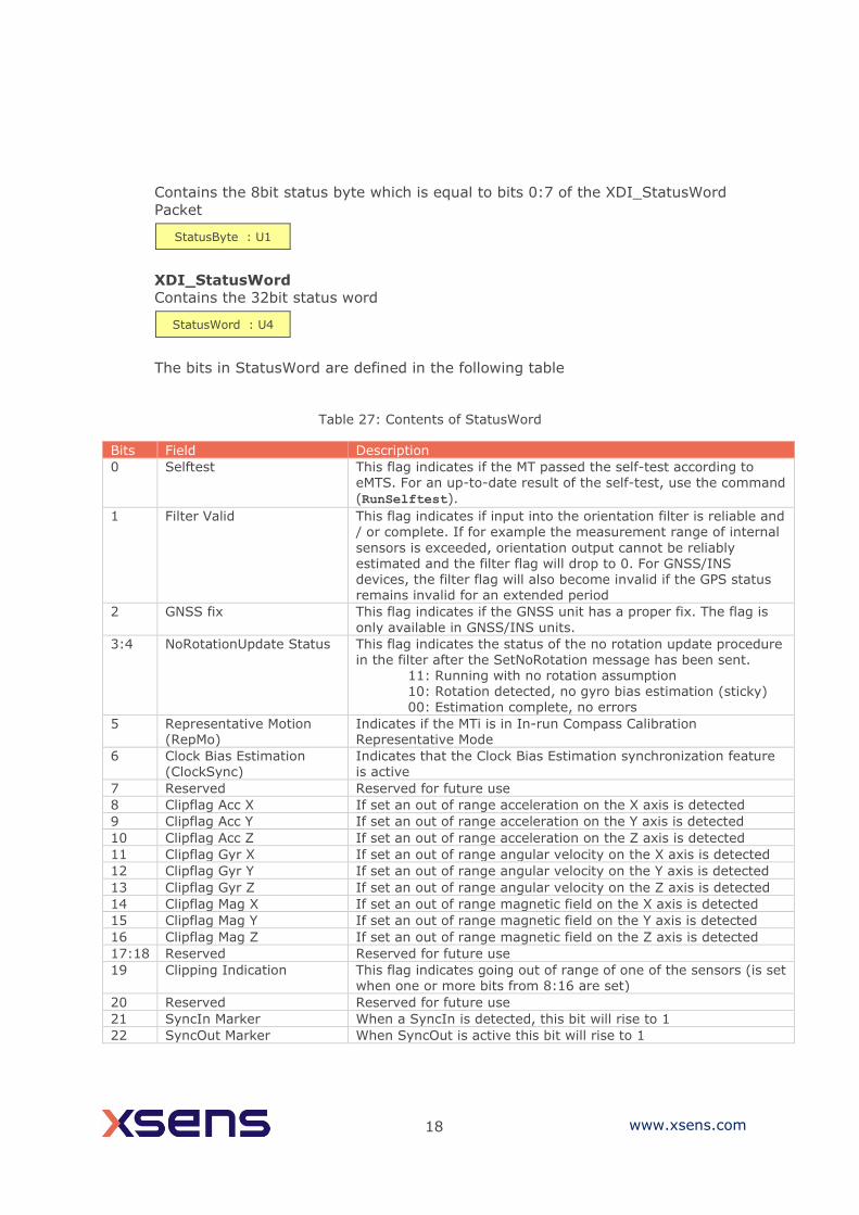
18 www.xsens.com
Contains the 8bit status byte which is equal to bits 0:7 of the XDI_StatusWord
Packet
XDI_StatusWord
Contains the 32bit status word
The bits in StatusWord are defined in the following table
Table 27: Contents of StatusWord
Bits Field Description
0 Selftest This flag indicates if the MT passed the self-test according to eMTS. For an up-to-date result of the self-test, use the command (RunSelftest).
1 Filter Valid This flag indicates if input into the orientation filter is reliable and / or complete. If for example the measurement range of internal
sensors is exceeded, orientation output cannot be reliably
estimated and the filter flag will drop to 0. For GNSS/INS devices, the filter flag will also become invalid if the GPS status remains invalid for an extended period
2 GNSS fix This flag indicates if the GNSS unit has a proper fix. The flag is
only available in GNSS/INS units.
3:4 NoRotationUpdate Status This flag indicates the status of the no rotation update procedure in the filter after the SetNoRotation message has been sent.
11: Running with no rotation assumption 10: Rotation detected, no gyro bias estimation (sticky) 00: Estimation complete, no errors
5 Representative Motion (RepMo)
Indicates if the MTi is in In-run Compass Calibration Representative Mode
6 Clock Bias Estimation (ClockSync)
Indicates that the Clock Bias Estimation synchronization feature is active
7 Reserved Reserved for future use
8 Clipflag Acc X If set an out of range acceleration on the X axis is detected
9 Clipflag Acc Y If set an out of range acceleration on the Y axis is detected
10 Clipflag Acc Z If set an out of range acceleration on the Z axis is detected
11 Clipflag Gyr X If set an out of range angular velocity on the X axis is detected
12 Clipflag Gyr Y If set an out of range angular velocity on the Y axis is detected
13 Clipflag Gyr Z If set an out of range angular velocity on the Z axis is detected
14 Clipflag Mag X If set an out of range magnetic field on the X axis is detected
15 Clipflag Mag Y If set an out of range magnetic field on the Y axis is detected
16 Clipflag Mag Z If set an out of range magnetic field on the Z axis is detected
17:18 Reserved Reserved for future use
19 Clipping Indication This flag indicates going out of range of one of the sensors (is set when one or more bits from 8:16 are set)
20 Reserved Reserved for future use
21 SyncIn Marker When a SyncIn is detected, this bit will rise to 1
22 SyncOut Marker When SyncOut is active this bit will rise to 1
StatusByte : U1
StatusWord : U4

19 www.xsens.com
23:25 Filter Mode Indicates Filter Mode, currently only available for GNSS/INS devices:
000: Without GNSS (filter profile is in VRU mode) 001: Coasting mode (GNSS has been lost <60 sec ago) 011: With GNSS (default mode)
26 HaveGnssTimePulse Indicates that the 1PPS GNSS time pulse is present
27:31 Reserved Reserved for future use
XDI_DeviceId
Contains the 32bit or 64bit Device ID.
XDI_LocationId
Contains the 16bit Location ID.
XDI_PositionEcef
Contains the position of the GNSS/INS in the Earth-Centered, Earth-Fixed (ECEF)
coordinate system in meters. Note that position in ECEF cannot be represented in
Fixed Point values because of the limited range of fixed point representations. Use
double or float representation instead.
XDI_LatLon
Contains the latitude and longitude in degrees of the GNSS/INS position.
XDI_AltitudeEllipsoid
Contains the altitude of the GNSS/INS in meters above the WGS-84 Ellipsoid.
XDI_VelocityXYZ
Contains the X, Y and Z components of the GNSS/INS velocity in m/s.
5.3.7 Filter messages
ReqLatLonAlt Direction To MT
MID 110 (0x6E)
DATA N/A
Valid in Config State
devId : U4 or U8
locId : U2
ecefX : ℝ ecefY : ℝ ecefZ : ℝ
lat : ℝ lon : ℝ
altEllipsoid : ℝ
velX : ℝ velY : ℝ velZ : ℝ
20 www.xsens.com
1 2 3 7 10 20 30 100 200 300 710 610 620 630 670
Requests the Latitude, Longitude and Altitude that is stored in the device. Latitude
Longitude and Altitude are used for local magnetic declination and local gravity.
ReqLatLonAltAck Direction To host
MID 111 (0x6F)
DATA LAT LON ALT (24 bytes)
Valid in Config State
1 2 3 7 10 20 30 100 200 300 710 610 620 630 670
Returns the Latitude, Longitude and Altitude that is stored in the device. Latitude
Longitude and Altitude are used for local magnetic declination and local gravity.
Table 28: Structure of stored LatLonAlt value
Data (byte offset) Description
LAT (0) Latitude in double floating point, big-endian
LON (8) Longitude in double floating point, big-endian
ALT (16) Altitude in double floating point, big-endian
SetLatLonAlt Direction To MT
MID 110 (0x6E)
DATA LAT LON ALT (24 bytes)
Valid in Config State
1 2 3 7 10 20 30 100 200 300 710 610 620 630 670
Sets the Latitude, Longitude and Altitude that is stored in the device. Latitude,
Longitude and Altitude are used for local magnetic declination and local gravity.
See ReqLatLonAltAck for description of DATA.
SetLatLonAltAck Direction To host
MID 111 (0x6F)
DATA N/A
Valid in Config State
1 2 3 7 10 20 30 100 200 300 710 610 620 630 670
ReqAvailableFilterProfiles Direction To MT
21 www.xsens.com
MID 98 (0x62)
Valid in Config State
2 3 7 20 30 200 300 710 620 630 670
Requests the available setting profiles from the on board memory of the Motion
Tracker.
AvailableFilterProfiles
Contains information about available setting profiles that are stored on the non-
volatile memory of the Motion Tracker.
Data contains the following for all 5 available setting profiles. When less than 5
filter profiles are available, the remaining filter profiles are of type 0.
Table 29: Structure of the AvailableFilterProfiles message
DATA (B) Description
TYPE (0 + 22*index) Filter profile type
VERSION (1 + 22*index) Filter profile version
LABEL (2 + 22*index) Filter profile label. The label is NOT 0-terminated and it is padded to 20 bytes with spaces.
ReqFilterProfile (Classic method) Direction To MT
MID 100 (0x64)
Valid in Config State
2 3 7 20 30 200 300 710
Requests the ID of the currently used filter profile.
SetFilterProfile (Classic Method) Direction To MT
MID 100 (0x64)
DATA FILTERPROFILE (2 bytes)
Valid in Config State
2 3 7 20 30 200 300 710
Sets the filter profile to use. For more information about the various setting
profiles please refer to the filter profile sections in the device specific manuals
([MTi_10s_100s]).

22 www.xsens.com
Table 30: List of available filter profiles
FILTERPROFILE Hardware Type Description
39 MTi 10-series/MTi 100-series General
40 MTi 10-series/MTi 100-series High_mag_dep
41 MTi 10-series/MTi 100-series Dynamic
42 MTi 10-series/MTi 100-series Low_mag_dep
43 MTi 10-series/MTi 100-series VRU_general
50 MTi 1-series General
51 MTi 1-series High_mag_dep
52 MTi 1-series Dynamic
53 MTi 1-series North_reference
54 MTi 1-series VRU_general
11 MTi-7 General
12 MTi-7 GeneralNoBaro
13 MTi-7 GeneralMag
01 MTi-G-710 General
02 MTi-G-710 GeneralNoBaro
03 MTi-G-710 GeneralMag
04 MTi-G-710 Automotive
05 MTi-G-710 HighPerformanceEDR
ReqFilterProfileAck (Classic Method) Direction To host MID 101 (0x65)
DATA VERSION FILTERPROFILE
Valid in Config State
2 3 7 20 30 200 300 710
Contains the currently used setting profile.
DATA (B) Description
VERSION (0) Filter profile version
FILTERPROFILE (1) Filter profile type
ReqFilterProfile (Modern method) Direction To MT
MID 100 (0x64)
Valid in Config State
620 630 670
Requests the string of the currently selected filter profile(s)
SetFilterProfile (Modern Method) Direction To MT
MID 100 (0x64)
23 www.xsens.com
DATA ASCII string (1 to 62 bytes)
Valid in Config State
620 630 670
Selects the filter profile(s) to use. Selection is done through a string containing
the labels of the filter profiles to select, separated by a ‘/’ character. The string is
case-sensitive and is not 0-terminated. Its length may not exceed 62 bytes.
The possibility to select multiple profiles at once is there for products that use a
tiered approach. For example to combine a base filter profile with specific heading
behaviour.
For more information about the various setting profiles and the tiered approach
please refer to the filter profile sections in the device specific manuals
([MTi_1s],[MTi_10s_100s],[MTi_600s]).
As an example, a valid filter profile selection string for an MTi-630 is:
“Robust/VRU”
It combines the “Robust” filter profile with the “VRU” heading behaviour. To set
this combination the data must be:
Offset 0 1 2 3 4 5 6 7 8 9
Data(ASCII) R o b u s t / V R U
Data(Hex) 52 6F 62 75 73 74 2F 56 52 55
ReqFilterProfileAck (Modern Method) Direction To host
MID 101 (0x65)
DATA ASCII string (1 to 62 bytes)
Valid in Config State
620 630 670
Contains the currently selected filter profile(s). See SetFilterProfile (Modern
Method) for details
ReqGnssPlatform MID 118 (0x76)
Direction To MT
Valid in Config State

24 www.xsens.com
7 710
Request the current GNSS navigation filter settings used. See SetGnssPlatform for
more information. Only for MTi-G-700/710 with FW version 1.7 or higher.
ReqGnssPlatformAck MID 119 (0x77)
DATA PLATFORM (2 bytes)
Direction To host
Valid in Config State
7 710
Returns the current GNSS navigation filter settings used. See SetGnssPlatform for
more information. Only for MTi-G-700/710 with FW version 1.7 or higher.
SetGnssPlatform MID 118 (0x76)
DATA PLATFORM (2 bytes)
Direction To MT
Valid in Config State
7 710
Sets the GNSS navigation filter settings to use. The setting influences the
behaviour of the Xsens filter output, so it is advised to use after consultation with
Xsens. Only for MTi-G-700/710 with FW version 1.7 or higher.
Table 31: List of available platforms for GNSS receiver
PLATFORM (uint16) Description
0 Portable
8 Airborne <4g
ResetOrientation MID 164 (0xA4)
DATA CODE (2 bytes)
Direction To MT
Valid in Config State and Measurement State
2 3 7 20 30 200 300 710 620 630 670
Reset the orientation. Different resets are supported; see Table 32. For more
information about the different resets see [FRM]. To store the new orientation go
to Config state and send the ResetOrientation message again but now with

25 www.xsens.com
CODE = 0x0000. If the orientation is not stored the next time, the Measurement
State becomes active the reset orientation results are discarded.
CODE
A two-byte value indicating which reset to perform during Measurement State. To
store the present settings, enter the Config State and send the same message
again with RESET equal to zero.
Table 32: Available orientation resets
CODE Description
0 (0x0000) Store current settings (only in config mode)
1 (0x0001) Heading reset (NOT supported by GNSS/INS devices)
2 (0x0002) RESERVED
3 (0x0003) Object or inclination reset
4 (0x0004) Alignment reset (heading and inclination)
5 (0x0005) Default heading
6 (0x0006) Default inclination
7 (0x0007) Default alignment
SetNoRotation MID 34 (0x22)
DATA Duration (seconds) (2 bytes)
Direction To MT
Valid in Measurement State
2 3 7 20 30 200 300 710 620 630 670
Initiates the ‘no rotation’ update procedure. The duration in seconds is the time in
which the MTi is considered to be lying still and the no rotation update is being
applied. For more information about the no rotation update procedure see [FRM]).
Note that the acknowledge message does not reflect the result of the
SetNoRotation message. The result of the SetNoRotation message are
represented in bits 3 and 4 of the Status Word (see MTdata2 / 0x36).
ReqUTCTime Direction To MT
MID 96 (0x60)
1 2 3 7 10 20 30 100 200 300 710 610 620 630 670
Request UTC Time from sensor
SetUTCTime Direction To MT
MID 96 (0x60)
26 www.xsens.com
DATA UTCTime (12 bytes)
1 2 3 7 10 20 30 100 200 300 710 610 620 630 670
Set UTC Time in the onboard memory of the MTi. GNSS/INS devices will
automatically set the UTC Time based on GNSS data.
AdjustUTCTime Direction To MT
MID 168 (0xA8)
DATA Correction ticks (4 bytes)
1 2 3 7 10 20 30 100 200 300 710 610 620 630 670
Sends correction ticks for the UTC Time to the sensor (1 tick is 0.1 ms).
Value must be provided in two’s complement 32-bit integer:
Table 33: Minimum and maximum correction ticks for AdjustUTCTime
Value Correction ticks (time in seconds)
0x00000001 1 (+0.0001 secs)
0x00002710 10000 (+1 sec)
0xFFFFD8EF0 -10000 (-1 sec)
UTCTime Direction To host
MID 97 (0x61)
DATA UTCTime (12 bytes)
1 2 3 7 10 20 30 100 200 300 710 610 620 630 670
Contains UTC Time Table 34: Structure of UTCTime
DATA (B) Description
0 Nanoseconds of second, range 0 .. 1.000.000.000
4 Year, range 1999 .. 2099
6 Month, range 1..12
7 Day of Month, range 1..31
8 Hour of Day, range 0..23
9 Minute of Hour, range 0..59
10 Seconds of Minute, range 0..59
11 0x01 = Valid Time of Week 0x02 = Valid Week Number 0x04 = Valid UTC

27 www.xsens.com
NOTE: Time until UTC flag (0x04) goes to valid takes 12.5 minutes. This time is
needed to correct for the clock bias of the receiver. It is advised to start
synchronization using UTC only when the UTC flag is valid.
IccCommand MID 116 (0x74)
DATA COMMAND (1 byte)
Direction To MT
Valid in Measurement State, Config state
2 3 7 20 30 200 300 710 620 630 670
Handles request and actions with respect to In-run Compass Calibration (ICC) and
Representative Motion.
Table 35: Available commands for IccCommand
COMMAND Action State
00 Start Representative Motion Measurement State
01 Stop Representative Motion Measurement State
02 Store ICC parameters Config State
03 Get Representative Motion State Measurement State
IccCommandAck MID 117 (0x75)
DATA RESULT (0-7 bytes, depending on the command)
Direction To host
Valid in Measurement State
2 3 7 20 30 200 300 710 620 630 670
Acknowledges IccCommand and may return a result based on the command.
Store ICC Paramaters is only valid in Config State.
Table 36: ICC RESULT communicated with IccCommandAck
Payload offset (bytes)
Type Length (bytes)
State
00 Uint8 1 IccCommand, see Table 35
01 Command-specific
N Command-specific additional payload (see Table 37)
Table 37: Payload of IccCommandAck
ICC Command Extra Payload for IccCommandAck (0x75)
Start Representative Motion (0x00) None
Stop Representative Motion (0x01) ICC results (see Table 38 for complete message
payload)
Store ICC results (0x02) None
28 www.xsens.com
Representative Motion state (0x03) State: - 0x00: representative motion inactive - 0x01: representative motion active
Table 38: ICCRESULTS
Payload offset (bytes)
Type Field
0 Uint8 Command = 0x01 = Stop Representative Motion
1 Float ddt value (Ratio of disturbance with respect to noise)
5 Uint8 Dimension of estimate (2D/3D)
6 Uint8 Status byte:
- 0x00 OK - 0x01 Too much disturbance - 0x02 Not enough data - 0x03 Too much disturbance and not enough data
Example: After Representative Motion is stopped, the MTi may return for example
the next message:
FA FF 75 07 01 40 80 3A 85 02 01
FA FF : Preamble and BusId
75 : Message ID (IccCommandAck)
01 : Stop Representative Motion
40 80 3A 85 : ddt value (4.0071435)
02 : Dimension (2D)
00 : No warnings
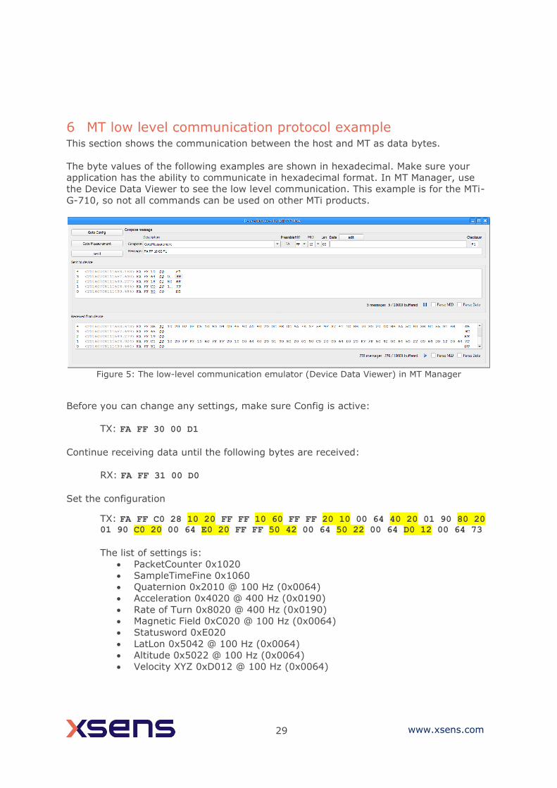
29 www.xsens.com
6 MT low level communication protocol example This section shows the communication between the host and MT as data bytes.
The byte values of the following examples are shown in hexadecimal. Make sure your
application has the ability to communicate in hexadecimal format. In MT Manager, use
the Device Data Viewer to see the low level communication. This example is for the MTi-
G-710, so not all commands can be used on other MTi products.
Figure 5: The low-level communication emulator (Device Data Viewer) in MT Manager
Before you can change any settings, make sure Config is active:
TX: FA FF 30 00 D1
Continue receiving data until the following bytes are received:
RX: FA FF 31 00 D0
Set the configuration
TX: FA FF C0 28 10 20 FF FF 10 60 FF FF 20 10 00 64 40 20 01 90 80 20 01 90 C0 20 00 64 E0 20 FF FF 50 42 00 64 50 22 00 64 D0 12 00 64 73
The list of settings is:
• PacketCounter 0x1020
• SampleTimeFine 0x1060
• Quaternion 0x2010 @ 100 Hz (0x0064)
• Acceleration 0x4020 @ 400 Hz (0x0190)
• Rate of Turn 0x8020 @ 400 Hz (0x0190)
• Magnetic Field 0xC020 @ 100 Hz (0x0064)
• Statusword 0xE020
• LatLon 0x5042 @ 100 Hz (0x0064)
• Altitude 0x5022 @ 100 Hz (0x0064)
• Velocity XYZ 0xD012 @ 100 Hz (0x0064)
30 www.xsens.com
Note the mask: e.g. LatLon, in the example fixed point 16.32, is also available
with fixed point 12.20. That part would then have been “50 41 00 64”.
The MT acknowledges with
RX: FA FF C1 28 10 20 FF FF 10 60 FF FF 20 10 00 64 40 20 01 90 80 20 01 90 C0 20 00 64 E0 20 FF FF 50 42 00 64 50 22 00 64 D0 12 00 64 72
Set the baud rate (serial communication only)
TX: FA FF 18 01 80 68
The MT acknowledges with
RX: FA FF 19 00 E8
Set the filter profile (in this case GeneralNoBaro for an MTi-G-710)
TX: FA FF 64 02 00 02 99
The MT acknowledges with
RX: FA FF 65 00 9C
Goto measurement state to start logging data:
TX: FA FF 10 00 F1
Start logging data:
The MT sends the MTData2 message which has the following format:
RX: FA FF 36 31 10 20 02 DF C5 10 60 04 00 45 9D A0 40 20 0C BE DC 9A FA 3F 54 9F 37 41 1C BB 70 80 20 0C BB AA 5C 80 3B 8C 55 01 BB 81 33
00 E0 20 04 00 00 00 81 45
The message is built up as following:
FA FF 36 Preamble, Bus ID and Message ID (0x36 is MTDATA2)
31 Length of all data
10 20 02 DF C5 In this case the highlighted part is the Packet counter (0x1020) with
length 0x02 and these 2 bytes are DF C5 (decimal: 57285). Double-
clicking a message in the data viewer will show the decimal value in
a pop-up screen.
… All data messages are following with total 0x31 bytes (49 bytes).
Last data packet is “E0 20 04 00 00 00 81”
45 Checksum for this Xbus message
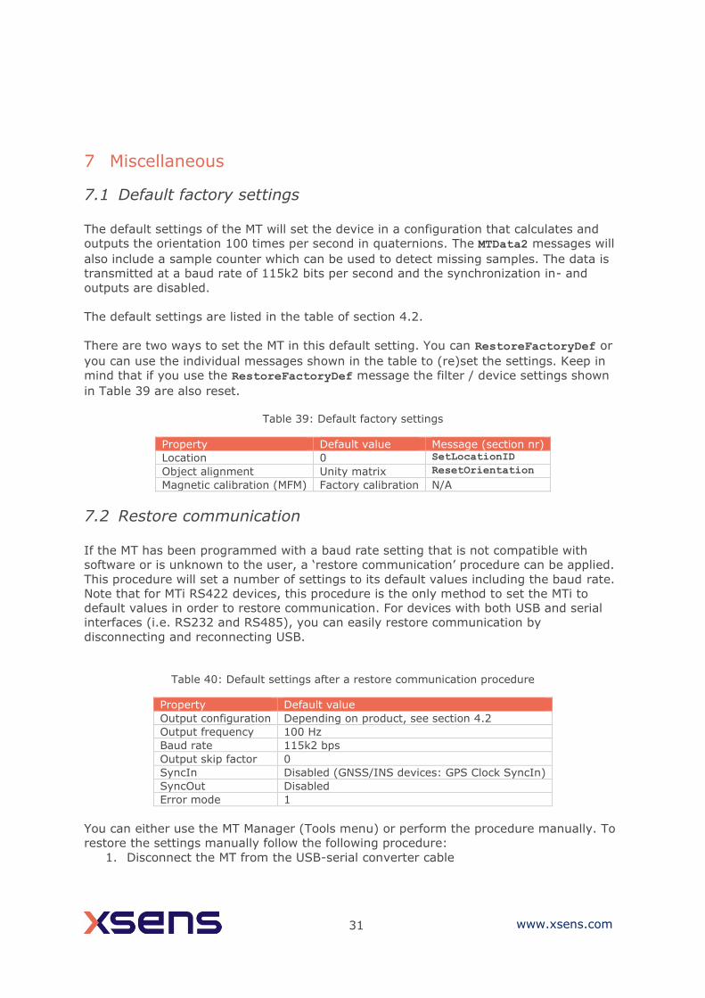
31 www.xsens.com
7 Miscellaneous
7.1 Default factory settings
The default settings of the MT will set the device in a configuration that calculates and
outputs the orientation 100 times per second in quaternions. The MTData2 messages will
also include a sample counter which can be used to detect missing samples. The data is
transmitted at a baud rate of 115k2 bits per second and the synchronization in- and
outputs are disabled.
The default settings are listed in the table of section 4.2.
There are two ways to set the MT in this default setting. You can RestoreFactoryDef or
you can use the individual messages shown in the table to (re)set the settings. Keep in
mind that if you use the RestoreFactoryDef message the filter / device settings shown
in Table 39 are also reset.
Table 39: Default factory settings
Property Default value Message (section nr)
Location 0 SetLocationID
Object alignment Unity matrix ResetOrientation
Magnetic calibration (MFM) Factory calibration N/A
7.2 Restore communication
If the MT has been programmed with a baud rate setting that is not compatible with
software or is unknown to the user, a ‘restore communication’ procedure can be applied.
This procedure will set a number of settings to its default values including the baud rate.
Note that for MTi RS422 devices, this procedure is the only method to set the MTi to
default values in order to restore communication. For devices with both USB and serial
interfaces (i.e. RS232 and RS485), you can easily restore communication by
disconnecting and reconnecting USB.
Table 40: Default settings after a restore communication procedure
Property Default value
Output configuration Depending on product, see section 4.2
Output frequency 100 Hz
Baud rate 115k2 bps
Output skip factor 0
SyncIn Disabled (GNSS/INS devices: GPS Clock SyncIn)
SyncOut Disabled
Error mode 1
You can either use the MT Manager (Tools menu) or perform the procedure manually. To
restore the settings manually follow the following procedure:
1. Disconnect the MT from the USB-serial converter cable
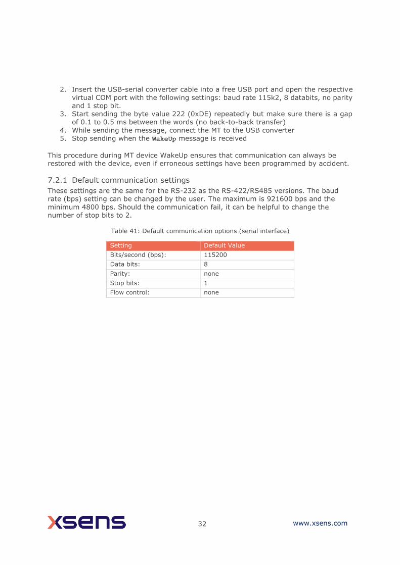
32 www.xsens.com
2. Insert the USB-serial converter cable into a free USB port and open the respective
virtual COM port with the following settings: baud rate 115k2, 8 databits, no parity
and 1 stop bit.
3. Start sending the byte value 222 (0xDE) repeatedly but make sure there is a gap
of 0.1 to 0.5 ms between the words (no back-to-back transfer)
4. While sending the message, connect the MT to the USB converter
5. Stop sending when the WakeUp message is received
This procedure during MT device WakeUp ensures that communication can always be
restored with the device, even if erroneous settings have been programmed by accident.
7.2.1 Default communication settings
These settings are the same for the RS-232 as the RS-422/RS485 versions. The baud
rate (bps) setting can be changed by the user. The maximum is 921600 bps and the
minimum 4800 bps. Should the communication fail, it can be helpful to change the
number of stop bits to 2.
Table 41: Default communication options (serial interface)
Setting Default Value
Bits/second (bps): 115200
Data bits: 8
Parity: none
Stop bits: 1
Flow control: none

33 www.xsens.com
8 Message Reference Listing This section gives a quick reference of all the valid messages. For more information about
the use of the messages see Section 5.
8.1 WakeUp and State messages (Section 5.3.1)
Message MID Direction
WakeUp 62 (0x3E) To host
WakeUpAck 63 (0x3F) To MT
GoToConfig 48 (0x30) To MT
GoToConfigAck 49 (0x31) To host
GoToMeasurement 16 (0x10) To MT
GoToMeasurementAck 17 (0x11) To host
Reset 64 (0x40) To MT
ResetAck 65 (0x41) To host
8.2 Informational messages (Section 5.3.2)
Message MID Direction
ReqDID 0 (0x00) To MT Host request device ID of the device
DeviceID 1 (0x01) To host Device acknowledges request by sending its ID
2 (0x02) To MT Reserved
3 (0x03) To host Reserved
ReqProductCode 28 (0x1C) To MT Host request product code of the device
ProductCode 29 (0x1D) To host Device acknowledges request by sending its product code
ReqHardwareVersion 30 (0x1E) To MT Host requests hardware revision of device
HardwareVersion 31 (0x1F) To host Device acknowledges request by sending its hardware revision
ReqFWRev 18 (0x12) To MT Host requests firmware revision of device
FirmwareRev 19 (0x13) To host Device acknowledges request by sending its firmware revision
10 (0x0A) To MT Reserved
11 (0x0B) To host Reserved
Error 66 (0x42) To host Error message
166 (0xA6) To MT Reserved
167 (0xA7) To host Reserved
8.3 Device-specific messages (Section 5.3.3) Message MID Direction Description
RestoreFactoryDef 14 (0xE) To MT Restores all settings in MT to factory defaults
ReqBaudrate 24 (0x18) To MT Requests current baud rate of the serial communication
ReqBaudrateAck 25 (0x19) To host Device returns baud rate of serial
communication
SetBaudrate 24 (0x18) To MT Host sets baud rate of serial communication
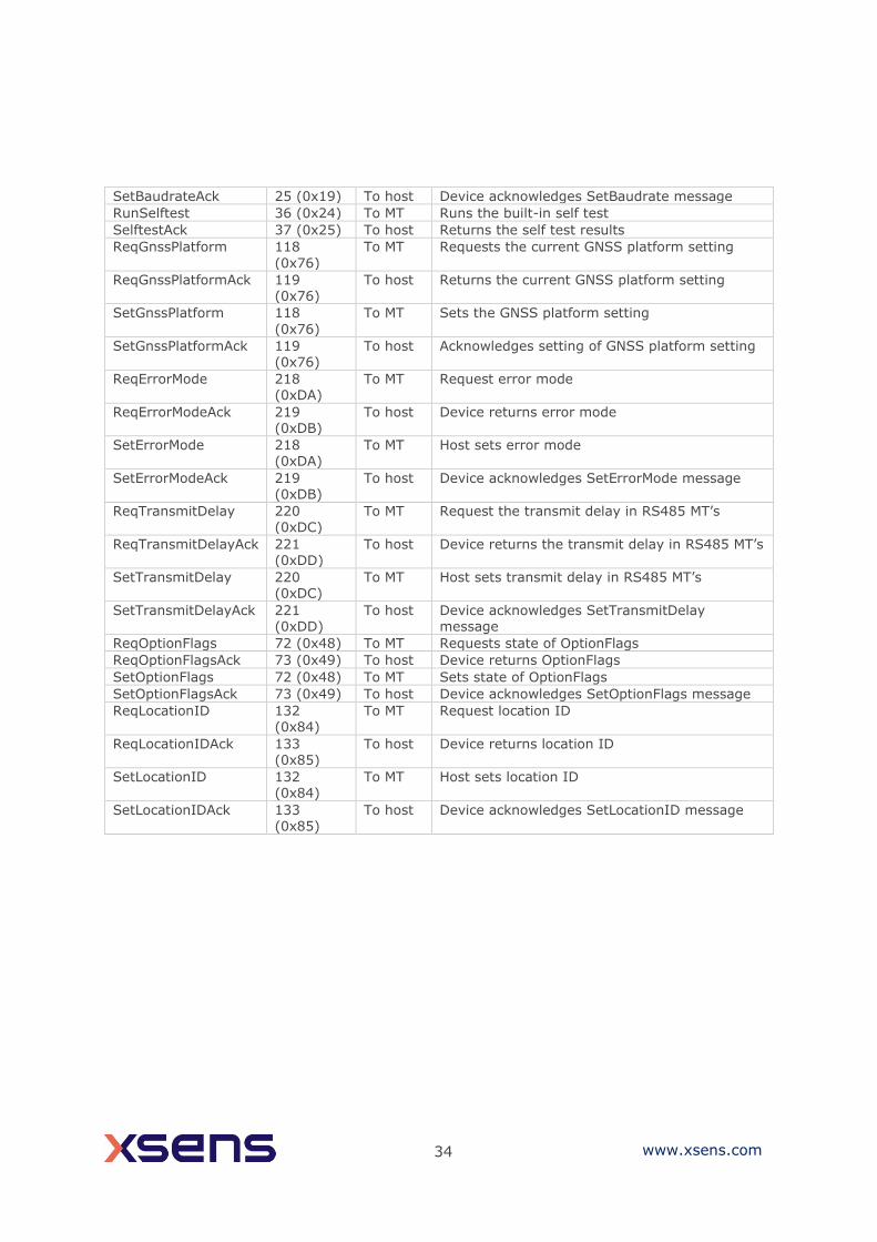
34 www.xsens.com
SetBaudrateAck 25 (0x19) To host Device acknowledges SetBaudrate message
RunSelftest 36 (0x24) To MT Runs the built-in self test
SelftestAck 37 (0x25) To host Returns the self test results
ReqGnssPlatform 118
(0x76)
To MT Requests the current GNSS platform setting
ReqGnssPlatformAck 119 (0x76)
To host Returns the current GNSS platform setting
SetGnssPlatform 118
(0x76)
To MT Sets the GNSS platform setting
SetGnssPlatformAck 119 (0x76)
To host Acknowledges setting of GNSS platform setting
ReqErrorMode 218 (0xDA)
To MT Request error mode
ReqErrorModeAck 219 (0xDB)
To host Device returns error mode
SetErrorMode 218 (0xDA)
To MT Host sets error mode
SetErrorModeAck 219 (0xDB)
To host Device acknowledges SetErrorMode message
ReqTransmitDelay 220 (0xDC)
To MT Request the transmit delay in RS485 MT’s
ReqTransmitDelayAck 221 (0xDD)
To host Device returns the transmit delay in RS485 MT’s
SetTransmitDelay 220 (0xDC)
To MT Host sets transmit delay in RS485 MT’s
SetTransmitDelayAck 221 (0xDD)
To host Device acknowledges SetTransmitDelay message
ReqOptionFlags 72 (0x48) To MT Requests state of OptionFlags
ReqOptionFlagsAck 73 (0x49) To host Device returns OptionFlags
SetOptionFlags 72 (0x48) To MT Sets state of OptionFlags
SetOptionFlagsAck 73 (0x49) To host Device acknowledges SetOptionFlags message
ReqLocationID 132 (0x84)
To MT Request location ID
ReqLocationIDAck 133 (0x85)
To host Device returns location ID
SetLocationID 132 (0x84)
To MT Host sets location ID
SetLocationIDAck 133 (0x85)
To host Device acknowledges SetLocationID message
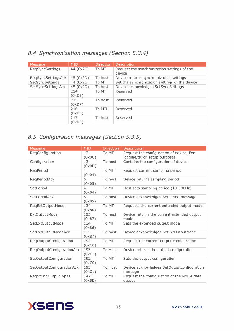
35 www.xsens.com
8.4 Synchronization messages (Section 5.3.4)
Message MID Direction Description
ReqSyncSettings 44 (0x2C) To MT Request the synchronization settings of the device
ReqSyncSettingsAck 45 (0x2D) To host Device returns synchronization settings
SetSyncSettings 44 (0x2C) To MT Set the synchronization settings of the device
SetSyncSettingsAck 45 (0x2D) To host Device acknowledges SetSyncSettings
214 (0xD6)
To MT Reserved
215 (0xD7)
To host Reserved
216 (0xD8)
To MTi Reserved
217 (0xD9)
To host Reserved
8.5 Configuration messages (Section 5.3.5)
Message MID Direction Description
ReqConfiguration 12 (0x0C)
To MT Request the configuration of device. For logging/quick setup purposes
Configuration 13 (0x0D)
To host Contains the configuration of device
ReqPeriod 4 (0x04)
To MT Request current sampling period
ReqPeriodAck 5 (0x05)
To host Device returns sampling period
SetPeriod 4 (0x04)
To MT Host sets sampling period (10-500Hz)
SetPeriodAck 5 (0x05)
To host Device acknowledges SetPeriod message
ReqExtOutputMode 134 (0x86)
To MT Requests the current extended output mode
ExtOutputMode 135
(0x87)
To host Device returns the current extended output
mode
SetExtOutputMode 134
(0x86)
To MT Sets the extended output mode
SetExtOutputModeAck 135 (0x87)
To host Device acknowledges SetExtOutputMode
ReqOutputConfiguration 192
(0xC0)
To MT Request the current output configuration
ReqOutputConfigurationAck 193 (0xC1)
To Host Device returns the output configuration
SetOutputConfiguration 192 (0xC0)
To MT Sets the output configuration
SetOutputConfigurationAck 193 (0xC1)
To Host Device acknowledges SetOutputconfiguration message
ReqStringOutputTypes 142
(0x8E)
To MT Request the configuration of the NMEA data
output

36 www.xsens.com
ReqStringOutputTypesAck 143 (0x8F)
To host Device returns the NMEA output configuration
SetStringOutputTypes 142 (0x8E)
To MT Configures the NMEA data output
SetStringOutputTypesAck 143
(0x8F)
To host Device acknowledges SetStringOutputTypes
message
212 (0xD4)
To MT Reserved
213
(0xD5)
To host Reserved
224 (0xE0)
To MT Reserved
225 (0xE1)
To host Reserved
ReqAlignmentRotation 236 (0xEC)
To MT Requests the sensor alignment or local alignment
ReqRotationQuaternionAck 237 (0xED)
To host Device acknowledges ReqRotationQuaternion
SetAlignmentRotation 236 (0xEC)
To MT Sets the sensor alignment or local alignment
SetRotationQuaternionAck 237 (0xED)
To host Device acknowledges SetRotationQuaternion
ReqOutputMode 208
(0xD0)
To MT Request current output mode (deprecated,
see rev W of this document)
ReqOutputModeAck 209 (0xD1)
To host Device returns output mode (deprecated, see rev W of this document)
SetOutputMode 208 (0xD0)
To MT Host sets output mode (deprecated, see rev W of this document)
SetOutputModeAck 209 (0xD1)
To host Device acknowledges SetOutputMode message (deprecated, see rev W of this document)
ReqOutputSettings 210 (0xD2)
To MT Request current output settings (deprecated, see rev W of this document)
ReqOutputSettingsAck 211 (0xD3)
To host Device returns output settings (deprecated, see rev W of this document)
SetOutputSettings 210 (0xD2)
To MT Host sets output settings (deprecated, see rev W of this document)
SetOutputSettingsAck 211 (0xD3)
To host Device acknowledges SetOutputSettings message (deprecated, see rev W of this document)
8.6 Data-related messages (Section 5.3.6)
Message MID Direction Description
ReqData 52 (0x34) To MT Host requests device to send MTData2 message
MTData 50 (0x32) To host Message with un-calibrated raw data, calibrated data, orientation data or GPS PVT data (obsolete)
MTData2 54 (0x36) To host Message with one or more output data packets
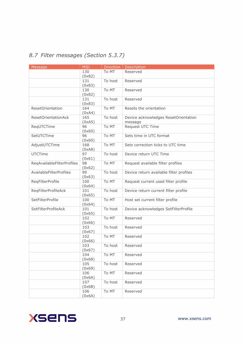
37 www.xsens.com
8.7 Filter messages (Section 5.3.7) Message MID Direction Description
130 (0x82)
To MT Reserved
131 (0x83)
To host Reserved
130 (0x82)
To MT Reserved
131 (0x83)
To host Reserved
ResetOrientation 164 (0xA4)
To MT Resets the orientation
ResetOrientationAck 165 (0xA5)
To host Device acknowledges ResetOrientation message
ReqUTCTime 96 (0x60)
To MT Request UTC Time
SetUTCTime 96
(0x60)
To MT Sets time in UTC format
AdjustUTCTime 168 (0xA8)
To MT Sets correction ticks to UTC time
UTCTime 97
(0x61)
To host Device return UTC Time
ReqAvailableFilterProfiles 98 (0x62)
To MT Request available filter profiles
AvailableFilterProfiles 99 (0x63)
To host Device return available filter profiles
ReqFilterProfile 100 (0x64)
To MT Request current used filter profile
ReqFilterProfileAck 101 (0x65)
To host Device return current filter profile
SetFilterProfile 100 (0x64)
To MT Host set current filter profile
SetFilterProfileAck 101 (0x65)
To host Device acknowledges SetFilterProfile
102 (0x66)
To MT Reserved
103 (0x67)
To host Reserved
102 (0x66)
To MT Reserved
103 (0x67)
To host Reserved
104 (0x68)
To MT Reserved
105 (0x69)
To host Reserved
106
(0x6A)
To MT Reserved
107 (0x6B)
To host Reserved
106
(0x6A)
To MT Reserved

38 www.xsens.com
107 (0x6B)
To host Reserved
ReqLatLonAlt 110 (0x6E)
To MT Requests the latitude, longitude and altitude that is stored in the device
ReqLatLonAltAck 111
(0x6F)
To host Returns the latitude, longitude and altitude
that is stored in the device
SetLatLonAlt 110 (0x6E)
To host Sets latitude, longitude and altitude in the device
SetLatLonAltAck 111
(0x6F)
To MT Device acknowledges SetLatLonAlt
32 (0x20)
To MT Reserved
33 (0x21)
To host Reserved
SetNoRotation 34 (0x22)
To MT Initiates ‘no rotation’ update procedure
SetNoRotationAck 35 (0x23)
To host Device acknowledges SetNoRotation message
IccCommand 116 (0x74)
To MT
IccCommandAck 117 (0x75)
To host
Related Documents