Communication Command Handling Instruction Manual 3390 Power Analyzer 9 This instruction manual handles only parts related to commands. 9 For communication settings, please refer to the instruction manual for the main unit 9 Care has been taken to ensure the accuracy of the contents in this instruction manual, however, please approach HIOKI’s Sales Planning Division or your nearest HIOKI dealer should you have any queries or found any mistakes. 9 Improvements may be made to this instruction manual without prior notice. 9 Unauthorized reproduction or copying of this instruction manual is prohibited. Inquiries HIOKI E. E. Corporation Sales Planning Division Address 81, Koizumi, Ueda, Nagano 386-1192 TEL 0268-28-0560 FAX 0268-28-0569 E-mail [email protected] URL http://www.hioki.co.jp HIOKI E. E. Corporation

Welcome message from author
This document is posted to help you gain knowledge. Please leave a comment to let me know what you think about it! Share it to your friends and learn new things together.
Transcript
Communication Command Handling Instruction Manual
3390
Power Analyzer
This instruction manual handles only parts related to commands.
For communication settings, please refer to the instruction manual for the main unit
Care has been taken to ensure the accuracy of the contents in this instruction
manual, however, please approach HIOKI’s Sales Planning Division or your
nearest HIOKI dealer should you have any queries or found any mistakes.
Improvements may be made to this instruction manual without prior notice.
Unauthorized reproduction or copying of this instruction manual is prohibited.
Inquiries HIOKI E. E. Corporation
Sales Planning Division
Address 81, Koizumi, Ueda, Nagano 386-1192
TEL 0268-28-0560
FAX 0268-28-0569
E-mail [email protected]
URL http://www.hioki.co.jp
HIOKI E. E. Corporation
3390 Power Analyzer Communication Command Handling Instruction Manual Second Revised Edition
2/92
1. Communication Command Overview.........................................................................................6
Command/Message..............................................................................................................................6
Command/Syntax .................................................................................................................................6
Command/Program Header..................................................................................................................7
Query Program Header.........................................................................................................................7
Response Message ..............................................................................................................................8
Terminator and Separator .....................................................................................................................8
Multiple-Command Header Omission ...................................................................................................9
2. Command Reference (Standard Command) ............................................................................10
Clear Standard Event Status Register (SESR) (except Output Queue) ..............................................10
Read Standard Event Status Register (SESR) ...................................................................................10
Query Instrument ID (Recognition Code)............................................................................................11
Set 1 for Output Queue When Finished All Pending Operations ........................................................11
Query Instrument Options...................................................................................................................12
Initialize Instrument .............................................................................................................................12
Request a Sampling ...........................................................................................................................12
Execute Next Command after Command Has Finished Processing...................................................13
3. Command Reference (Device-Specific Commands) ................................................................14
Set and Query Frequency Full Scale .................................................................................................14
Set and Query Coefficient of Integrated Full Scale .............................................................................14
Set and Query D/A Output Items ........................................................................................................15
Select and Query Waveform Output ...................................................................................................15
Select and Query Auto Range Limit ....................................................................................................16
Set and Query Average.......................................................................................................................16
Set and Query LCD Backlight .............................................................................................................17
Select and Query Beep Sound ...........................................................................................................17
Set and Query Efficiency, Pin of Loss Calculation Formula ................................................................18
Set and Query Efficiency, Pout of Loss Calculation Formula ..............................................................18
Set and Query Automatic Saving ........................................................................................................19
Query Existence of CF Card ...............................................................................................................19
Acquire File Name in CF Card ............................................................................................................20
Acquire Folder Name in CF Card........................................................................................................20
Acquire File Data in CF Card ..............................................................................................................21
Set and Query Time............................................................................................................................22
Set and Query Current Auto Range ....................................................................................................23
Select and Query Current Rectifier Type ............................................................................................23
Set and Query Current Range ............................................................................................................24
Initialize Data of Saved Items .............................................................................................................25
Set and Query Efficiency, Saved Items of Loss Calculation Value......................................................25
Set and Query Saved Items of Option Input .......................................................................................26
3390 Power Analyzer Communication Command Handling Instruction Manual Second Revised Edition
3/92
Initialize Harmonic Saved Data Items .................................................................................................26
Select and Query Harmonic List Saved Items ....................................................................................27
Set and Query Output Order of Harmonic Data Saving ......................................................................28
Set and Query Saved Items of Integration Values ..............................................................................29
Set and Query Noise Peak Value Saving............................................................................................30
Set and Query Saved Items of Normal Measurement Values in Respective Channels ......................31
Set and Query Saved Items of SUM’s Normal Measurement Values .................................................32
Set and Query Saved Items of Voltage Data .....................................................................................33
Set and Query Saved Items of Current Data ......................................................................................34
Select and Query ON/OFF of ∆-Y Calculation ....................................................................................35
Execute and Query Zero Adjust ..........................................................................................................35
Select and Query Display Screen Color..............................................................................................36
Select and Query Start Up Screen......................................................................................................36
Change Display Screen ......................................................................................................................37
Select and Query Motor Analysis Option Channel A Input ..................................................................37
Set and Query Motor Analysis Option Channel A Input Frequency Range ........................................38
Set and Query Motor Analysis Option Channel A Rating Torque ........................................................38
Select and Query Low-pass Filter of Motor Analysis Option ..............................................................39
Execute and Clear Motor Analysis Option’s Phase Zero Adjust..........................................................39
Set and Query Motor Analysis Option Channel A Range ...................................................................40
Set and Query Motor Analysis Option Channel A Scaling ...................................................................40
Set and Query Input Frequency Source for Motor Analysis Option’s Slip Calculation ........................41
Set and Query Motor Analysis Option’s Motor Synchronized Sources................................................41
Select and Query Motor Analysis Option Channel A Unit....................................................................42
Execute Zero Adjust of Motor Analysis Option ....................................................................................42
Set and Query Motor Analysis Option Channel B Range ...................................................................43
Set and Query Pulse ON/OFF of Motor Analysis Option Channel B Input ..........................................43
Set and Query ON/OFF of Motor Analysis Option Channel Z Input ....................................................44
Set and Query Motor Analysis Option Channel B Measured Maximum Frequency ............................44
Set and Query Motor Analysis Option Motor Pole Value.....................................................................45
Set and Query Pulse Values of Motor Analysis Option Channel B......................................................45
Set and Query Motor Analysis Option Channel B Scaling...................................................................46
Select and Query Motor Analysis Option Channel B Units..................................................................46
Select and Query Noise Analysis Measurement Channel ..................................................................47
Set and Query Noise Lower Limit Frequency .....................................................................................47
Select and Query Noise Analysis Point Values ...................................................................................48
Select and Query Noise Analysis Sampling Speed.............................................................................48
Set and Query Noise Analysis Window Function ................................................................................49
Set and Query Zero Cross Filter .........................................................................................................49
Set and Query Measurement Lower Limit Frequency.........................................................................50
3390 Power Analyzer Communication Command Handling Instruction Manual Second Revised Edition
4/92
Select and Query Frequency Measurement Source ...........................................................................50
Select and Query Harmonic Synchronized Source.............................................................................51
Set and Query THD Calculation Formula............................................................................................51
Set and Query Header for Response Message ..................................................................................52
Set and Query Hold Status .................................................................................................................52
Set and Query Integration Mode.........................................................................................................53
Execute Integration Data Reset ..........................................................................................................53
Execute Integration (Time) Start .........................................................................................................54
Query Integration (Time) .................................................................................................................54
Execute Integration (Time) Stop..........................................................................................................54
Set and Query Interval Time ...............................................................................................................55
Set and Query IP Address ..................................................................................................................56
Set and Query Default Gateway .........................................................................................................56
Set and Query Subnet Mask...............................................................................................................57
Set and Query Key Lock .....................................................................................................................57
Set and Query Main Instrument Display Language ............................................................................58
Select and Query Low Pulse Filter (LPF) ...........................................................................................58
Query Measurement Data...................................................................................................................59
Query Harmonic Measurement Data ..................................................................................................60
Query Noise Measurement Value Data...............................................................................................61
Query Voltage Noise Measurement Value Data..................................................................................61
Query Current Noise Measurement Value Data..................................................................................61
Initialize Communication Output Item Data.........................................................................................62
Set and Query Efficiency, Loss Calculation Value Communication Output Items ...............................62
Set and Query Communication Output Items of Option Input .............................................................63
Initialize Harmonic Communication Output Data Items.......................................................................63
Select and Query Harmonic List Communication Output Items ..........................................................64
Set and Query Communication Output Items of Integration Value......................................................65
Set and Query Output Order of Harmonic Data Communication Output.............................................66
Set and Query Normal Measurement Value Communication Output Items of Respective Channels .67
Set and Query SUM’s .............................68Normal Measurement Value Communication Output Items
Set and Query Voltage Data Communication Output Items ................................................................69
Set and Query Current Data Communication Output Items ................................................................70
Query Existence of USB Memory .......................................................................................................71
Acquire File Name in USB Memory ....................................................................................................71
Acquire Folder Name in USB Memory................................................................................................72
Acquire File Data in USB Memory ......................................................................................................72
Select and Query Wiring Mode ...........................................................................................................73
Set and Query Execution Confirmation Message ...............................................................................74
Select and Query RS232C Communication Speed.............................................................................74
3390 Power Analyzer Communication Command Handling Instruction Manual Second Revised Edition
5/92
Select and Query RS232C Connection Terminal ................................................................................75
Set and Query Automatic Saving Folder Name ..................................................................................75
Set and Query Manual Saving Folder Name ......................................................................................76
Select and Query Manual Saving Media Location ..............................................................................76
Set and Query CT Ratio......................................................................................................................77
Set and Query VT Ratio......................................................................................................................77
Set and Query Synchronized Source..................................................................................................78
Select and Query Actual Time ON/OFF ..............................................................................................78
Set and Query Actual Time Start Time ................................................................................................79
Set and Query Actual Time Stop Time ................................................................................................80
Select and Query Master/Slave of Synchronized Control Master ......................................................81
Set and Query Synchronized Event Items ..........................................................................................81
Select and Query Timer Control ON/OFF ...........................................................................................82
Set and Query Timer ..........................................................................................................................82
Set and Query Numerical Data Format...............................................................................................83
Set and Query Response Message Unit Separator ............................................................................84
Set and Query Voltage Auto Range ....................................................................................................85
Select and Query Voltage Rectifier Type ............................................................................................85
Set and Query Voltage Range ............................................................................................................86
Set and Query Zero Suppress ............................................................................................................87
4. ..........................................................................88Fundamental Measurement Item Parameters
5. .......................................................................................................................92Troubleshooting
3390 Power Analyzer Communication Command Handling Instruction Manual Second Revised Edition
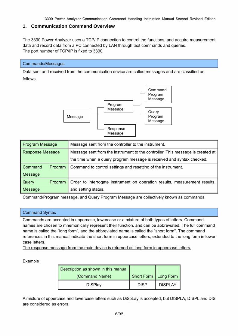
1. Communication Command Overview The 3390 Power Analyzer uses a TCP/IP connection to control the functions, and acquire measurement data and record data from a PC connected by LAN through text commands and queries. The port number of TCP/IP is fixed to 3390.
Commands/Messages
Data sent and received from the communication device are called messages and are classified as
follows.
Message
Program Message
Response Message
Command Program Message
Query Program Message
Program Message Message sent from the controller to the instrument.
Response Message Message sent from the instrument to the controller. This message is created at
the time when a query program message is received and syntax checked.
Command Program
Message
Command to control settings and resetting of the instrument.
Query Program
Message
Order to interrogate instrument on operation results, measurement results,
and setting status.
Command/Program message, and Query Program Message are collectively known as commands.
Command Syntax
Commands are accepted in uppercase, lowercase or a mixture of both types of letters. Command names are chosen to mnemonically represent their function, and can be abbreviated. The full command name is called the "long form", and the abbreviated name is called the "short form". The command references in this manual indicate the short form in uppercase letters, extended to the long form in lower case letters. The response message from the main device is returned as long form in uppercase letters.
Example
Description as shown in this manual
(Command Name)
Short Form
Long Form
DISPlay DISP DISPLAY
A mixture of uppercase and lowercase letters such as DiSpLay is accepted, but DISPLA, DISPL and DIS are considered as errors.
6/92

3390 Power Analyzer Communication Command Handling Instruction Manual Second Revised Edition
Command Program Header
A header shows what kind of function that command has.
A command always requires a header and comes in three types, “Simple Command Type”, “Compound
Command Type”, and “Standard Command Type”.
Types of Commands Description
Explanation
Simple Command Type
A sequence of letters
[Example] :HEADer ON
Compound Command
Type
Multiple simple command type headers separated by colons ":"
[Example] :VOLTage1:RANGe 600
Standard Command
Type
Begins with an asterisk "*", indicating that it is a standard command defined
by IEEE 488.2.
[Example] *RST
Data
Simple Command Type
Data
Compound Command Type
Query Program Header
These commands are used to interrogate the instrument about the results of operations and settings. A
query is formed by appending a question mark "?" after a program header
Types of Commands Description
Simple Command Type
A sequence of letters
[Example] :HEADer?
Compound Command
Type
Multiple simple command type headers separated by colons ":"
[Example] :VOLTage1:RANGe?
Standard Command
Type
Begins with an asterisk "*", indicating that it is a standard command defined
by IEEE 488.2.
[Example] *IDN?
Simple Command Type
Compound Command Type
7/92
3390 Power Analyzer Communication Command Handling Instruction Manual Second Revised Edition
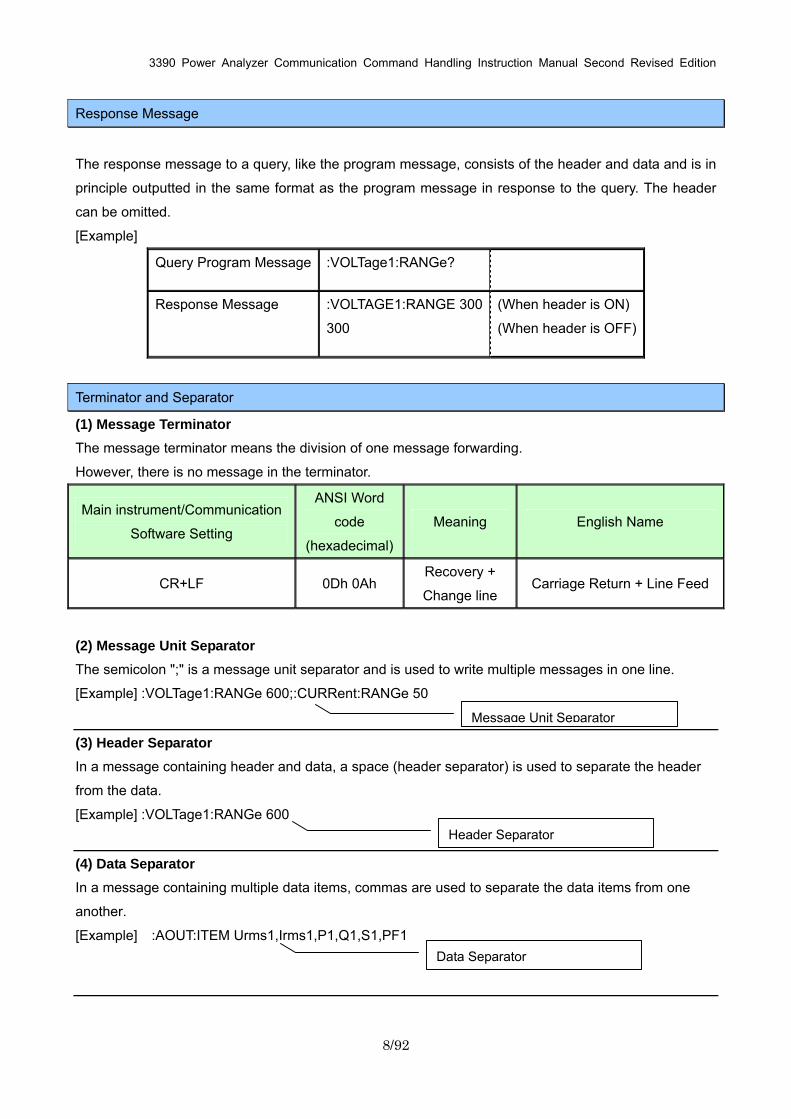
Response Message
The response message to a query, like the program message, consists of the header and data and is in
principle outputted in the same format as the program message in response to the query. The header
can be omitted.
[Example]
Query Program Message :VOLTage1:RANGe?
Response Message :VOLTAGE1:RANGE 300
300
(When header is ON)
(When header is OFF)
Terminator and Separator
(1) Message Terminator The message terminator means the division of one message forwarding.
However, there is no message in the terminator.
Main instrument/Communication
Software Setting
ANSI Word
code
(hexadecimal)
Meaning English Name
CR+LF 0Dh 0Ah Recovery +
Change line Carriage Return + Line Feed
(2) Message Unit Separator The semicolon ";" is a message unit separator and is used to write multiple messages in one line.
[Example] :VOLTage1:RANGe 600;:CURRent:RANGe 50
(3) Header Separator In a message containing header and data, a space (header separator) is used to separate the header
from the data.
[Example] :VOLTage1:RANGe 600
(4) Data Separator In a message containing multiple data items, commas are used to separate the data items from one
another.
[Example] :AOUT:ITEM Urms1,Irms1,P1,Q1,S1,PF1
Data Separator
Header Separator
Message Unit Separator
8/92
3390 Power Analyzer Communication Command Handling Instruction Manual Second Revised Edition
9/92
Multiple-Command Header Omission
When several commands having a common header are combined to form a compound command
if they are written together in sequence, the common portion can be omitted. This common portion is
called the "current path", and until it is cleared, the interpretation of subsequent commands presumes
that they share the same common portion.
This usage of the current path is shown in the following example:
Full Expression :VOLTage1:RANGe 600;:VOLTage1:MEAN OFF
Compacted Expression :VOLTage1:RANGe 600;MEAN OFF
The current path is cleared when the power is turned on, when reset by key input, by a colon ":" at the
start of a command, and when a message terminator is detected.
Standard command messages can be executed regardless of the current path. They have no effect
upon the current path.
A colon ":" is not required at the start of the header of a Simple or Compound command. However, to
avoid confusion with abbreviated forms and operating mistakes, we recommend always placing a colon
at the start of a header.
3390 Power Analyzer Communication Command Handling Instruction Manual Second Revised Edition
10/92
2. Command Reference (Standard Command) Clear Standard Event Status Register (SESR) (except Output Queue)
Syntax Command *CLS
Example Clear Event Register. (SESR)
Note ・No effect on Output Cue.
Read Standard Event Status Register (SESR)
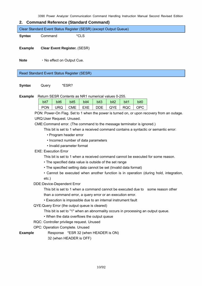
Syntax Query *ESR? Example Return SESR Contents as NR1 numerical values 0-255.
bit7 bit6 bit5 bit4 bit3 bit2 bit1 bit0 PON URQ CME EXE DDE QYE RQC OPC
PON: Power-On Flag. Set to 1 when the power is turned on, or upon recovery from an outage. URQ:User Request. Unused. CME:Command error. (The command to the message terminator is ignored.)
This bit is set to 1 when a received command contains a syntactic or semantic error: • Program header error • Incorrect number of data parameters • Invalid parameter format
EXE: Execution Error This bit is set to 1 when a received command cannot be executed for some reason. • The specified data value is outside of the set range • The specified setting data cannot be set (Invalid data format) • Cannot be executed when another function is in operation (during hold, integration, etc.)
DDE:Device-Dependent Error This bit is set to 1 when a command cannot be executed due to some reason other than a command error, a query error or an execution error. • Execution is impossible due to an internal instrument fault
QYE:Query Error (the output queue is cleared) This bit is set to "1" when an abnormality occurs in processing an output queue. • When the data overflows the output queue
RQC: Controller privilege request. Unused OPC: Operation Complete. Unused
Example Response *ESR 32 (when HEADER is ON) 32 (when HEADER is OFF)
3390 Power Analyzer Communication Command Handling Instruction Manual Second Revised Edition
11/92
Query Device ID (Recognition Code)
Syntax Query *IDN?
Example Query Instrument ID.
Response “Maker’s name”, “Model name”, “Serial number”, “Software version”
Description Response HIOKI,3390,081225345,V1.00
InstrumentID is HIOKI,3390,081225345, and software version is 1.00.
Note "*IDN?" is the last query message inside the program message.
Therefore, any subsequent query (in the same line) that is detected will lead to a query
error and no response message will be outputted.
Set 1 for Output Queue When Finished All Pending Operations
Syntax Query *OPC?
Description When the command (of transferred commands) prior to the *OPC command has
finished processing, “1” is stored in the output queue.
Response 1
Example :DEMAG;*OPC?
:After DEMAG command has finished processing, 1 is stored in the output queue.
3390 Power Analyzer Communication Command Handling Instruction Manual Second Revised Edition
12/92
Query Instrument Options
Syntax Query *OPT?
Description Queries the types of options available in the instrument.
Options are available from 9791, 9792, or 9793 or 0 when it is not available.
Response CH1 sensor, CH2 sensor, CH3 sensor, CH4 sensor, option, option serial
Response Example
ACDC500, ACDC500, ACDC500, ACDC500, 9793, 081108288
Note "*OPT?" is the last query message inside the program message.
Therefore, any subsequent query (in the same line) that is detected will lead to a query
error and no response message will be outputted.
Initialize Instrument
Syntax Command *RST
Description Initializes all instrument settings besides language and communication setting and returns
them to factory default.
Example *RST
Request a Sampling
Syntax Command *TRG
Description Performs one measurement when the display values or peak values are held.
Example :HOLD ON;*TRG;:MEAS?

3390 Power Analyzer Communication Command Handling Instruction Manual Second Revised Edition
13/92
Execute Next Command after Command Has Finished Processing
Syntax Command *WAI
Description Commands after *WAI will not be executed until the next update has finished.
Example :MEAS?;*WAI;*MEAS?
Data will be retrieved each time the display is updated.
Note Display data will not change even when a command is executed when peak values are
held.
3390 Power Analyzer Communication Command Handling Instruction Manual Second Revised Edition
14/92
3. Command Reference (Device-Specific Commands) Set and Query Frequency Full Scale
Syntax Command :AOUT:FREQuency (Frequency Data)
Query :AOUT:FREQuency?
Response Frequency Data :100Hz/500Hz/1kHz/5kHz
Description Command Sets the maximum frequency of D/A output’s Frequency Full Scale and the
motor.
Query Sets the maximum frequency of D/A output’s Frequency Full Scale and
returns it as words.
Example Command :AOUT:FREQ 100Hz
Set the Frequency Full Scale of D/A output as 100Hz.
Query :AOUT:FREQ?
Response :AOUT:FREQUENCY 100Hz (when HEADER is ON)
100Hz (when HEADER is OFF)
Note The settings for the D/A output’s Frequency Full Scale and the motor measured maximum
frequency are the same.
Set and Query Coefficient of Integrated Full Scale
Syntax Command :AOUT:INTEGrate <Magnification data>
Query :AOUT:INTEGrate?
Response Magnification Data :1/10,1/2,1,5,10,50,100,500,1000,5000,10000
Description Command Sets the integration full scale coefficient of D/A Output.
Query Sets the integration full scale coefficient of D/A output and returns it as
words.
Example Command :AOUT:INTEG 1
Set the coefficient of the D/A integration full scale as 1.
Query :AOUT:INTEG?
Response :AOUT:INTEGRATE 1 (when HEADER is ON)
1 (when HEADER is OFF)
3390 Power Analyzer Communication Command Handling Instruction Manual Second Revised Edition
15/92
Set and Query D/A Output Items
Syntax Command :AOUT:ITEM “Item 1”, “Item 2”,.......,”Item 16”
Query :AOUT:ITEM?
Response “Item 1”, “Item 2”, “Item 3”,.......,”Item 15”, “Item 16”
“Item 1 – 16” = Basic measured item parameters (Refer to 4. Basic Measured
Item Parameters)
Description Command Sets the D/A output item. Output items can be specified from 1 to 16.
Output items in the unspecified D/A channels will not be changed.
Query Sets the D/A output items and return them as words.
Example Command :AOUT:ITEM Urms1,Irms1,P1,Q1,S1,PF1
Set the D/A outputs from Channel 1 in sequence as Voltage CH1 RMs,
Current CH1 RMS, Effective Current CH1, Ineffective Current CH1, Apparent
Power CH1, and Power Factor Ch1.
Query :AOUT:ITEM?
Response :AOUT:ITEM
Urms1,Irms1,P1,Q1,S1,PF1,OFF,OFF,OFF,OFF,OFF,OFF
,OFF,OFF,OFF,OFF (when HEADER is ON)
Urms1,Irms1,P1,Q1,S1,PF1,OFF,OFF,OFF,OFF,OFF,OFF,OFF,OFF,OFF
,OFF (when HEADER is OFF) (when HEADER is OFF)
Select and Query Waveform Output
Syntax Command :AOUT:MONitor <ON/OFF>
Query :AOUT:MONitor?
Response ON : Waveform output ON
OFF : Waveform output OFF
Description Command Sets the Waveform output ON/OFF.
Query Returns the setting of the waveform output as ON or OFF.
Example Command :AOUT:MON ON
Set the Monitor output as ON.
Query :AOUT:MON?
Response :AOUT:MONITOR ON (when HEADER is ON)
ON (when HEADER is OFF)
3390 Power Analyzer Communication Command Handling Instruction Manual Second Revised Edition
16/92
Select and Query Auto Range Limit
Syntax Command :AUTOrange <WIDE/NARROW>
Query :AUTOrange?
Response <WIDE/NARROW>
WIDE : Widen the auto range limit.
NARROW : Narrow the auto range limit.
Description Command Selects to widen or narrow the auto range limit.
Query Returns the auto range limit as words.
Example Command :AUTO WIDE
Widen the auto range limit.
Query :AUTO?
Response :AUTORANGE WIDE (when HEADER is ON)
WIDE (when HEADER is OFF)
Set and Query Average
Syntax Command :AVEraging:MODE <OFF/FAST/MID/SLOW>
Query :AVEraging:MODE?
Response <OFF/FAST/MID/SLOW>
Explanation Command Sets the average.
Query Returns the average setting as words.
Example Command :AVE:MODE FAST
Set the average to FAST.
Query :AVE:MODE?
Response :AVERAGING:MODE FAST (when HEADER is ON)
FAST (when HEADER is OFF)
Note When the average setting is changed, the average processing will be restarted.
3390 Power Analyzer Communication Command Handling Instruction Manual Second Revised Edition
17/92
Set and Query LCD Backlight
Syntax Command :BACKlight <ON/1min/5min/10min/30min/60min>
Query :BACKlight?
Response <ON/1min/5min/10min/30min/60min>
Description Command Sets the LCD Backlight.
Query Returns the LCD Backlight setting as words.
Example Command :BACK 30min
Set the LCD Backlight to turn off automatically 30 minutes later.
Query :BACK?
Response :BACKLIGHT 30min (when HEADER is ON)
30min (when HEADER is OFF)
Select and Query Beep Sound
Syntax Command :BEEPer <ON/OFF>
Query :BEEPer?
Response <ON/OFF>
Description Command Set the beep sound ON/OFF.
Query Returns the On/OFF beep sound setting as ON or OFF.
Example Command :BEEP ON
Set the beep sound ON.
Query :BEEP?
Response :BEEPER ON (when HEADER is ON)
ON (when HEADER is OFF)
3390 Power Analyzer Communication Command Handling Instruction Manual Second Revised Edition
18/92
Set and Query Efficiency, Pin of Loss Calculation Formula
Syntax Command :CALCulate[number]:PIN <P1/P2/P3/P4/P12/P34/P123/Pm>
Query :CALCulate[number]:PIN?
[number] ・・・・ 1,2,3
Response “P1/P2/P3/P4/P12/P34/P123/Pm”
Description Command Sets Efficiency, Pin of Loss Calculation Formula. Query Returns the settings of efficiency, Pin of Loss Calculation Formula as
words.
Example Command :CALC1:PIN P1
Set the Pin of the Calculation formula 1 as P1.
Query :CALC1:PIN?
Response :CALCULATE1:PIN P1 (when HEADER is ON)
P1 (when HEADER is OFF)
Note When P12/P34/P123 cannot be selected because of wiring settings, they cannot be specified.
Pm cannot be specified except when it can be selected during the implementation of the motor
analysis option.
Set and Query Efficiency, Pout of Loss Calculation Formula
Syntax Command :CALCulate[number]:POUT <P1/P2/P3/P4/P12/P34/P123/Pm>
Query :CALCulate[number]:POUT?
[number] ・・・・ 1,2,3
Response “P1/P2/P3/P4/P12/P34/P123/Pm”
Description Command Sets the items for Efficiency, Pout of Loss Calculation Formula.
Query Returns the setting items for Pout of Loss Calculation Formula as words.
Example Command :CALC1:POUT Pm
Set the Pout item of Calculation Formula 1 as P1.
Query :CALC1:POUT?
Response :CALCULATE1:POUT Pm (when HEADER is ON)
Pm (when HEADER is OFF)
Note When P12/P34/P123 cannot be selected because of wiring settings, they cannot be specified.
3390 Power Analyzer Communication Command Handling Instruction Manual Second Revised Edition
19/92
Pm cannot be specified except when it can be selected during the implementation of the motor
analysis option.
Set and Query Automatic Saving
Syntax Command :CARD:AUTO:SAVE <ON/OFF>
Query :CARD:AUTO:SAVE?
Response <ON/OFF>
ON: Automatic Save on
OFF: Automatic Save off
Description Command Sets the automatic saving to the CF Card On or OFF
Query Returns the setting for the automatic saving to the CF Card as On or OFF.
Example Command :CARD:AUTO:SAVE ON
Set the automatic saving to the CF Card ON.
Query :CARD:AUTO:SAVE?
Response :CARD:AUTO:SAVE ON (when HEADER is ON)
ON (when HEADER is OFF)
Query Existence of CF Card
Syntax Query :CARD:EXISt?
Response <Y/N>
Y:CF Card Exist
N:CF Card Doesn’t exist
Description Query Returns the existence of the CF Card in the instrument with Y or N.
Example Query :CARD:EXIS?
Response :CARD:EXIST Y (when HEADER is ON)
Y (when HEADER is OFF)
3390 Power Analyzer Communication Command Handling Instruction Manual Second Revised Edition
20/92
Acquire File Name in CF Card
Syntax Query :CARD:FILEname? “Specified Folder Name”
“Specified Folder Name”
Acquire the file name under the specified folder name.
When omitted, acquire the file name under the root folder.
Response “File name”, “Byte count”, “File name”, “Byte count”…
The order of “File name”, “Byte count” will continue for as long as there are
files.
When there are no more files, the words “NO_FILE” will be returned.
Description Query Acquires the file name under the folder specified from the CF card.
Example Query :CARD:FILE? HI3390
Acquire and return the file name under the HI3390 folder from the CF card.
Response :CARD:FILENAME H3390001.BMP,44862,M3390000.CSV,578 (when
HEADER is ON)
3390001.BMP,44682,M3390000.CSV,578 (when HEADER is OFF)
Note Up to 90 files displayed from the start of the screen can be acquired.
When more than 90 files exist in the same folder, subsequent file names cannot be acquired.
Acquire Folder Name in CF Card
Syntax Query :CARD:FOLDername?
Response “Folder name”, “Folder name”, “Folder name”…
Folder names will continue for as long as there are folders.
When there are no more folders, the words “NO_FOLDER” will be
returned.
Description Query Acquires the folder name under the root of the CF card.
Example Query :CARD:FOLD?
Response :CARD:FOLDERNAME HI3390 (when HEADER is ON)
HI3390 (when HEADER is OFF))
Note Up to 215 folders displayed from the start of the screen can be acquired.
When more than 215 folders exist in the root, subsequent folder names cannot be acquired.
3390 Power Analyzer Communication Command Handling Instruction Manual Second Revised Edition
21/92
Acquire File Data in CF Card
Syntax Query :CARD:PICKout? “File name”, “Start position”, “Stop position”,
“Specified folder name”,
Response “File name”, “Start position”, “Stop position”, “Specified folder name”
File name :File name to be forwarded
Start position :Specify the acquired start position in the file with byte count
Stop position :Specify the acquired stop position in the file with byte count
Specified Folder Name:Search for file name under the specified folder
When omitted, search for the file name under the root.
Description Query Reads the specified file name under the folder from the CF card from the
start position to the stop position, attach STX (02) to the start and ETX (03) to
the end of the data to be forwarded, and forward data.
Example Query :CARD:PICK? 02030100.CSV,1,1000,HI3390
Return the 1-100 byte data of the 02030100.CSV file under the HI3390 folder
from the CF card.
Response STX(02)HIOKI 3390・・・・・ETX(03)
Note Even when the header is set as ON, headers will not attach to Response data.
Specify “1” if the beginning of the file is made the start position.
STX/ETX is not a ASCII Code but (02)/(03) of the Binary Data.
3390 Power Analyzer Communication Command Handling Instruction Manual Second Revised Edition
22/92
Set and Query Time
Syntax Command :CLOCk “Year Data”, “Month Data”, “Day Data”, “Hour Data”, “Minute
Data”, “Second Data”
Query :CLOCk?
Response “Year Data”, “Month Data”, “Day Data”, “Hour Data”, “Minute Data”, “Second
Data”
Year Data: 2000 - 2079 (can be set 00 – 79)
Month Data: 01- 12
Day Data: 01 - 31
Hour Data: 00 - 23
Minute Data: 00 - 59
Second Data: 0
Description Command Sets the time of the clock in the main instrument.
Query Returns the time setting of the main instrument as NRI numerical values.
Example Command :CLOC 08,12,25,12,30,0
Set as 2008 December 25th 12:30:0
Query :CLOC?
Response :CLOCK 2008,12,25,12,30,45 (when HEADER is ON)
2008,12,25,12,30,45 (when HEADER is OFF)
Note The instrument can interpret days of the month as well as leap years, so specifying an
improbable date will lead to an error.
Always set 0 for the second data.
3390 Power Analyzer Communication Command Handling Instruction Manual Second Revised Edition
23/92
Set and Query Current Auto Range
Syntax Command :CURRent[CH]:AUTO <ON/OFF>
Query :CURRent[CH]:AUTO?
[CH] ・・・・ 1,2,3,4
Response ON: Measure current with auto range.
OFF: Measure current with manual range.
Description Command Set the current auto range ON/OFF.
Query Returns the current auto range setting with ON or OFF.
Example Command :CURR1:AUTO ON
Set the auto range of the Current Channel 1 to ON.
Query :CURR1:AUTO?
Response :CURRENT1:AUTO ON (when HEADER is ON)
ON (when HEADER is OFF)
Note When the range is set with the :CURRent[CH]:RANGeCommand, the auto range of the
specified channel will be OFF.
By combining measurement lines (for above IP3W), the auto ranges of other channels which
are combined are also set.
Select and Query Current Rectifier Type
Syntax Command :CURRent[CH]:MEAN <ON/OFF>
Query :CURRent[CH]:MEAN?
[CH] ・・・・ 1,2,3,4
Response ON: Set the current rectifier type to MEAN.
OFF: Set the current rectifier type to RMS.
Description Command Select the RMS/MEAN of the current rectifier type.
Query Returns the selection of the RMS/MEAN of the rectifier type as ON (MEAN)
or OFF (RMS).
Example Command :CURR1:MEAN OFF
Select the current rectifier type of Current Channel 1 as RMS.
Query :CURR1:MEAN?
3390 Power Analyzer Communication Command Handling Instruction Manual Second Revised Edition
24/92
Response :CURRENT1:MEAN OFF (when HEADER is ON)
OFF (WHEN HEADER IS OFF)
Note By combining measurement lines (for above IP3W), the current rectifier types of other channels
which are combined are also set.
Set and Query Current Range
Syntax Command :CURRent[CH]:RANGe <Current Range(NR2)>
Query :CURRent[CH]:RANGe?
[CH] ・・・・ 1,2,3,4
Response 0.4/0.8/1.0/2.0/4.0/5.0/8.0/10.0/20.0/40.0/50.0/80.0/100.0/200.0/500.0
Description Command Specifies current range. (Unit is [A])
The numerical value can be in NRf format, but rounding is performed for
figures beyond the last valid decimal place. (Valid digits: 4 digits)
Query Queries the current range setting. Returns the current range as a numerical
value in NR2 format.
Example Command :CURR1:RANG 1.0
Set the current Channel 1 to 1A range.
Query :CURR1:RANG?
Response :CURRENT1:RANGE 1.0 (WHEN HEADER IS ON)
1.0 (WHEN HEADER IS OFF)
Note • Do not add a unit to the measurement range.
• Wait until the internal circuit has stabilized after changing a range before reading
measurements.
• When the range is specified, the auto range of the specified channel will be OFF.
• By combining measurement lines (for above IP3W), the settings for the auto ranges of other
channels which are combined are also changed.
3390 Power Analyzer Communication Command Handling Instruction Manual Second Revised Edition
25/92
Initialize Data of Saved Items
Syntax Command :DATAout:ITEM:ALLClear
Description Command Initializes the saved data items.
Returns the saved data items to factory defaults.
Example Command :DATA:ITEM:ALLC
Initialize the saved data items.
Set and Query Efficiency, Saved Items of Loss Calculation Value
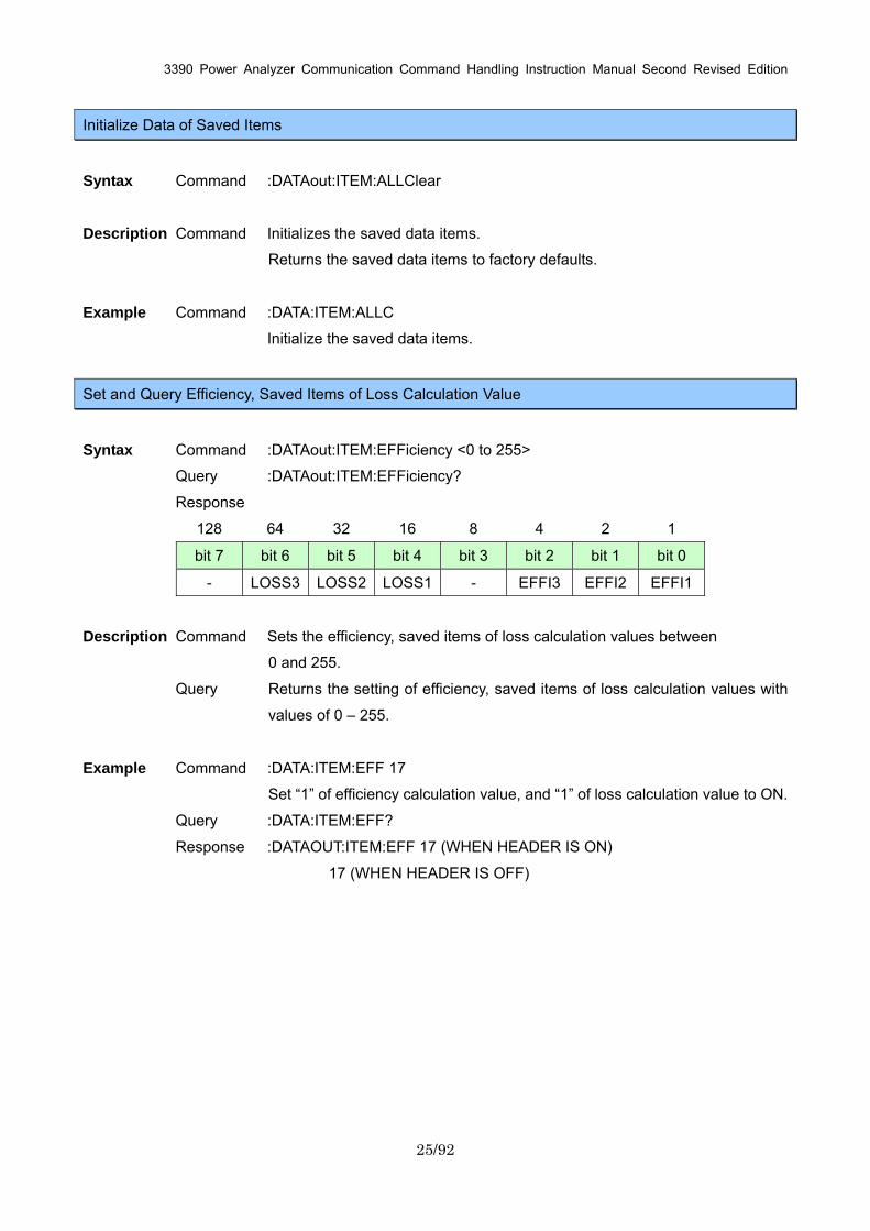
Syntax Command :DATAout:ITEM:EFFiciency <0 to 255>
Query :DATAout:ITEM:EFFiciency?
Response
128 64 32 16 8 4 2 1
bit 7 bit 6 bit 5 bit 4 bit 3 bit 2 bit 1 bit 0
- LOSS3 LOSS2 LOSS1 - EFFI3 EFFI2 EFFI1
Description Command Sets the efficiency, saved items of loss calculation values between
0 and 255.
Query Returns the setting of efficiency, saved items of loss calculation values with
values of 0 – 255.
Example Command :DATA:ITEM:EFF 17
Set “1” of efficiency calculation value, and “1” of loss calculation value to ON.
Query :DATA:ITEM:EFF?
Response :DATAOUT:ITEM:EFF 17 (WHEN HEADER IS ON)
17 (WHEN HEADER IS OFF)
3390 Power Analyzer Communication Command Handling Instruction Manual Second Revised Edition
26/92
Set and Query Saved Items of Option Input
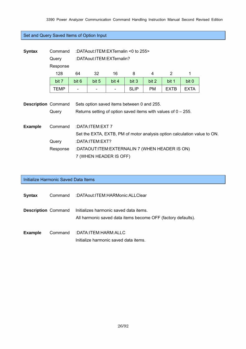
Syntax Command :DATAout:ITEM:EXTernalin <0 to 255>
Query :DATAout:ITEM:EXTernalin?
Response
128 64 32 16 8 4 2 1
bit 7 bit 6 bit 5 bit 4 bit 3 bit 2 bit 1 bit 0
TEMP - - - SLIP PM EXTB EXTA
Description Command Sets option saved items between 0 and 255.
Query Returns setting of option saved items with values of 0 – 255.
Example Command :DATA:ITEM:EXT 7
Set the EXTA, EXTB, PM of motor analysis option calculation value to ON.
Query :DATA:ITEM:EXT?
Response :DATAOUT:ITEM:EXTERNALIN 7 (WHEN HEADER IS ON)
7 (WHEN HEADER IS OFF)
Initialize Harmonic Saved Data Items
Syntax Command :DATAout:ITEM:HARMonic:ALLClear
Description Command Initializes harmonic saved data items.
All harmonic saved data items become OFF (factory defaults).
Example Command :DATA:ITEM:HARM:ALLC
Initialize harmonic saved data items.
3390 Power Analyzer Communication Command Handling Instruction Manual Second Revised Edition
27/92
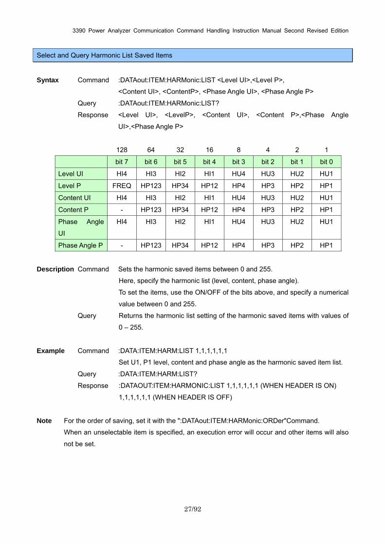
Select and Query Harmonic List Saved Items
Syntax Command :DATAout:ITEM:HARMonic:LIST <Level UI>,<Level P>,
<Content UI>, <ContentP>, <Phase Angle UI>, <Phase Angle P>
Query :DATAout:ITEM:HARMonic:LIST?
Response <Level UI>, <LevelP>, <Content UI>, <Content P>,<Phase Angle
UI>,<Phase Angle P>
128 64 32 16 8 4 2 1
bit 7 bit 6 bit 5 bit 4 bit 3 bit 2 bit 1 bit 0
Level UI HI4 HI3 HI2 HI1 HU4 HU3 HU2 HU1
Level P FREQ HP123 HP34 HP12 HP4 HP3 HP2 HP1
Content UI HI4 HI3 HI2 HI1 HU4 HU3 HU2 HU1
Content P - HP123 HP34 HP12 HP4 HP3 HP2 HP1
Phase Angle
UI
HI4 HI3 HI2 HI1 HU4 HU3 HU2 HU1
Phase Angle P - HP123 HP34 HP12 HP4 HP3 HP2 HP1
Description Command Sets the harmonic saved items between 0 and 255.
Here, specify the harmonic list (level, content, phase angle).
To set the items, use the ON/OFF of the bits above, and specify a numerical
value between 0 and 255.
Query Returns the harmonic list setting of the harmonic saved items with values of
0 – 255.
Example Command :DATA:ITEM:HARM:LIST 1,1,1,1,1,1
Set U1, P1 level, content and phase angle as the harmonic saved item list.
Query :DATA:ITEM:HARM:LIST?
Response :DATAOUT:ITEM:HARMONIC:LIST 1,1,1,1,1,1 (WHEN HEADER IS ON)
1,1,1,1,1,1 (WHEN HEADER IS OFF)
Note For the order of saving, set it with the ":DATAout:ITEM:HARMonic:ORDer"Command.
When an unselectable item is specified, an execution error will occur and other items will also
not be set.
3390 Power Analyzer Communication Command Handling Instruction Manual Second Revised Edition
28/92
Set and Query Output Order of Harmonic Data Saving
Syntax Command :DATAout:ITEM:HARMonic:ORDer <Lower limit order>, <Upper limit
order>,<ODD/EVEN/ALL>
Query :DATAout:ITEM:HARMonic:ORDer?
Response Lower limit order (NR1) :0 - 100
Upper limit order (NR1) :0 - 100
ODD : Odd-number order only
EVEN : Even-number order only
ALL : All orders
Description Command Sets the upper limit, lower limit orders, even-number,
odd-number and all orders for the harmonic saved items.
Use in combination with
":DATAout:ITEM:HARMonic:LIST"Command.
Query Returns the setting for the order of the harmonic saved items with numerical
and character string.
Example Command :DATA:ITEM:HARM:ORD 1,15,ODD
Set the odd-number order from 1 – 15 to the default output.
Query :DATA:ITEM:HARM:ORD?
Response :DATAOUT:HARMONIC:ORDER 1,15,ODD (WHEN HEADER IS ON)
1,15,ODD (WHEN HEADER IS OFF)
3390 Power Analyzer Communication Command Handling Instruction Manual Second Revised Edition
29/92
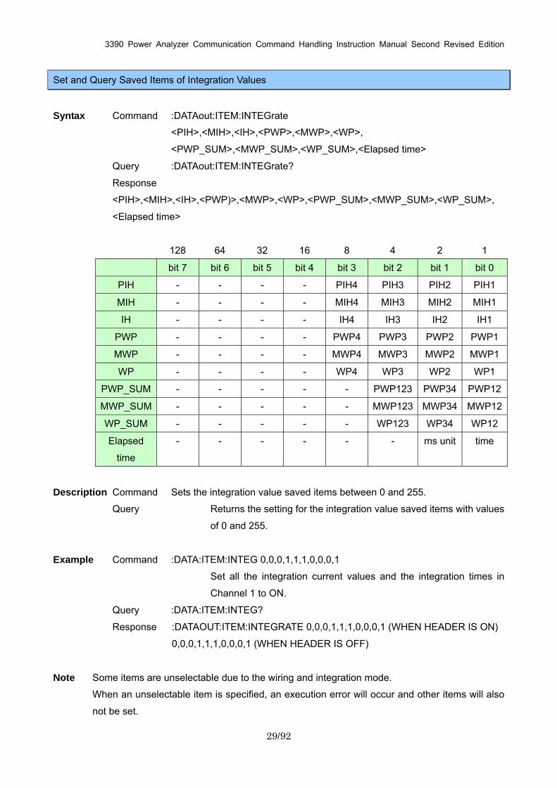
Set and Query Saved Items of Integration Values
Syntax Command :DATAout:ITEM:INTEGrate
<PIH>,<MIH>,<IH>,<PWP>,<MWP>,<WP>,
<PWP_SUM>,<MWP_SUM>,<WP_SUM>,<Elapsed time>
Query :DATAout:ITEM:INTEGrate?
Response
<PIH>,<MIH>,<IH>,<PWP)>,<MWP>,<WP>,<PWP_SUM>,<MWP_SUM>,<WP_SUM>,
<Elapsed time>
128 64 32 16 8 4 2 1
bit 7 bit 6 bit 5 bit 4 bit 3 bit 2 bit 1 bit 0
PIH - - - - PIH4 PIH3 PIH2 PIH1
MIH - - - - MIH4 MIH3 MIH2 MIH1
IH - - - - IH4 IH3 IH2 IH1
PWP - - - - PWP4 PWP3 PWP2 PWP1
MWP - - - - MWP4 MWP3 MWP2 MWP1
WP - - - - WP4 WP3 WP2 WP1
PWP_SUM - - - - - PWP123 PWP34 PWP12
MWP_SUM - - - - - MWP123 MWP34 MWP12
WP_SUM - - - - - WP123 WP34 WP12
Elapsed
time
- - - - - - ms unit time
Description Command Sets the integration value saved items between 0 and 255.
Query Returns the setting for the integration value saved items with values
of 0 and 255.
Example Command :DATA:ITEM:INTEG 0,0,0,1,1,1,0,0,0,1
Set all the integration current values and the integration times in
Channel 1 to ON.
Query :DATA:ITEM:INTEG?
Response :DATAOUT:ITEM:INTEGRATE 0,0,0,1,1,1,0,0,0,1 (WHEN HEADER IS ON)
0,0,0,1,1,1,0,0,0,1 (WHEN HEADER IS OFF)
Note Some items are unselectable due to the wiring and integration mode.
When an unselectable item is specified, an execution error will occur and other items will also
not be set.
3390 Power Analyzer Communication Command Handling Instruction Manual Second Revised Edition
30/92
Set and Query Noise Peak Value Saving
Syntax Command :DATAout:ITEM:NOISepeak <ON/OFF>
Query :DATAout:ITEM:NOISepeak?
Response ON :Output noise peak value
OFF :Do not output noise peak value
Description Command Sets noise peak value saving.
Query Returns noise peak value save setting with ON or OFF.
Example Command :DATA:ITEM:NOIS ON
Set the noise peak value saving to ON.
Query :DATA:ITEM:NOIS?
Response :DATAOUT:ITEM:NOISEPEAK ON (WHEN HEADER IS ON)
ON (WHEN HEADER IS OFF)

3390 Power Analyzer Communication Command Handling Instruction Manual Second Revised Edition
31/92
Set and Query Saved Items of Normal Measurement Values in Respective Channels
Syntax Command :DATAout:ITEM:NORMal <U Data>,<I Data>,<P Data>,<S Data>,
<Q Data>,<PF Data>,<DEG Data>,<FREQ Data>
Query :DATAout:ITEM:NORMal?
Response <U Data>,<I Data>,<P Data>,<S Data>,<Q Data>,
<PF Data>,<DEG Data>,<FREQ Data>
128 64 32 16 8 4 2 1
bit 7 bit 6 bit 5 bit 4 bit 3 bit 2 bit 1 bit 0
U Data - - - - U4 U3 U2 U1
I Data - - - - I4 I3 I2 I1
P Data - - - - P4 P3 P2 P1
S Data - - - - S4 S3 S2 S1
Q Data - - - - Q4 Q3 Q2 Q1
PF Data - - - - PF4 PF3 PF2 PF1
DEG Data - - - - DEG4 DEG3 DEG2 DEG1
FREQ Data - - - - FREQ4 FREQ3 FREQ2 FREQ1
Description Command Sets the saved normal measurement value items to the
numerical value 0 - 255.
Query Returns the saved normal measurement value items of the respective
channels as numerical values. Example Command :DATA:ITEM:NORM 1,1,1,0,0,1,0,0
Set the voltage, current, effective power and power factor data of Channel 1
to ON.
Query :DATA:ITEM:NORM?
Response :DATAOUT:ITEM:NORMAL 1,1,1,0,0,1,0,0 (WHEN HEADER IS ON)
1,1,1,0,0,1,0,0 (WHEN HEADER IS OFF)
Note Under this command, when U is turned to ON, all the U items in the specified channel
(:DATAout:ITEM:U) become ON, and when U is turned OFF, all the U items in the specified
channel become OFF.
(:DATAout:ITEM:I) become ON, and when I is turned OFF, all the I items in the specified
channel become OFF.
To specify individually saved items in the U data and I data,
use :DATAout:ITEM:U, :DATAout:ITEM:I after this command is executed.
During Query, if even 1 item in the channel is turned to ON, the channel will become ON.
3390 Power Analyzer Communication Command Handling Instruction Manual Second Revised Edition
32/92
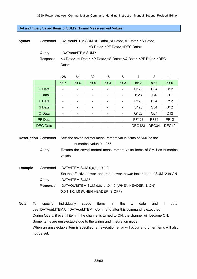
Set and Query Saved Items of SUM’s Normal Measurement Values
Syntax Command :DATAout:ITEM:SUM <U Data>,<I Data>,<P Data>,<S Data>,
<Q Data>,<PF Data>,<DEG Data>
Query : DATAout:ITEM:SUM?
Response <U Data>, <I Data>,<P Data>,<S Data>,<Q Data>,<PF Data>,<DEG
Data>
128 64 32 16 8 4 2 1
bit 7 bit 6 bit 5 bit 4 bit 3 bit 2 bit 1 bit 0
U Data - - - - - U123 U34 U12
I Data - - - - - I123 I34 I12
P Data - - - - - P123 P34 P12
S Data - - - - - S123 S34 S12
Q Data - - - - - Q123 Q34 Q12
PF Data - - - - - PF123 PF34 PF12
DEG Data - - - - - DEG123 DEG34 DEG12
Description Command Sets the saved normal measurement value items of SMU to the
numerical value 0 – 255.
Query Returns the saved normal measurement value items of SMU as numerical
values.
Example Command :DATA:ITEM:SUM 0,0,1,1,0,1,0
Set the effective power, apparent power, power factor data of SUM12 to ON.
Query :DATA:ITEM:SUM?
Response :DATAOUT:ITEM:SUM 0,0,1,1,0,1,0 (WHEN HEADER IS ON)
0,0,1,1,0,1,0 (WHEN HEADER IS OFF)
Note To specify individually saved items in the U data and I data,
use :DATAout:ITEM:U, :DATAout:ITEM:I Command after this command is executed.
During Query, if even 1 item in the channel is turned to ON, the channel will become ON.
Some items are unselectable due to the wiring and integration mode.
When an unselectable item is specified, an execution error will occur and other items will also
not be set.

3390 Power Analyzer Communication Command Handling Instruction Manual Second Revised Edition
33/92
Set and Query Saved Items of Voltage Data
Syntax Command :DATAout:ITEM:U <CH 1>,< CH 2>,< CH 3>,< CH
4>,<SUM12>,<SUM34>,<SUM123>
Query :DATAout:ITEM:U?
Response <CH 1>,< CH 2>,< CH 3>,< CH 4>,<SUM12>,<SUM34>,<SUM123>
128 64 32 16 8 4 2 1
bit 7 bit 6 bit 5 bit 4 bit 3 bit 2 bit 1 bit 0
CH 1 PK- PK+ THD/RF FND DC AC MN RMS
CH 2 PK- PK+ THD/RF FND DC AC MN RMS
CH 3 PK- PK+ THD/RF FND DC AC MN RMS
CH 4 PK- PK+ THD/RF FND DC AC MN RMS
SUM12 - - - - - - MN RMS
SUM34 - - - - - - MN RMS
SUM123 - - - - UNB - MN RMS
Description Command Sets the saved voltage data items to the numerical value 0 – 255.
Query Returns the saved voltage data items as numerical values.
Example Command :DATA:ITEM:U 1,1,1,1,0,0,0
Set the voltage RMSdata of Channels 1 – 4 to ON.
Query :DATA:ITEM:U?
Response :DATAOUT:ITEM:U 1,1,1,1,0,0,0 (WHEN HEADER IS ON)
1,1,1,1,0,0,0 (WHEN HEADER IS OFF)
Note Data in the THD/RF items changes according to the integration mode setting.
Some items are unselectable due to the wiring and integration mode.
When an unselectable item is specified, an execution error will occur and other items will also
not be set.
Use this command after :DATAout:ITEM:NORMal and :DATAout:ITEM:SUMCommand.
3390 Power Analyzer Communication Command Handling Instruction Manual Second Revised Edition
34/92
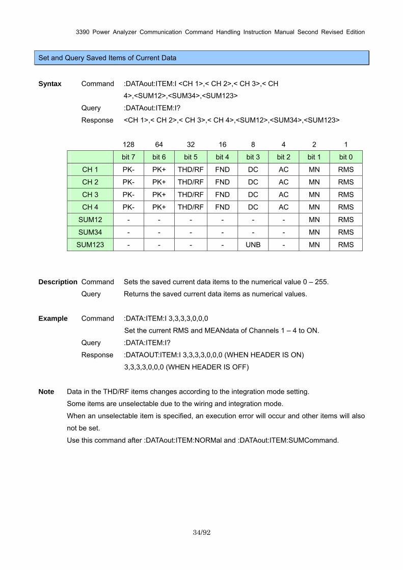
Set and Query Saved Items of Current Data
Syntax Command :DATAout:ITEM:I <CH 1>,< CH 2>,< CH 3>,< CH
4>,<SUM12>,<SUM34>,<SUM123>
Query :DATAout:ITEM:I?
Response <CH 1>,< CH 2>,< CH 3>,< CH 4>,<SUM12>,<SUM34>,<SUM123>
128 64 32 16 8 4 2 1
bit 7 bit 6 bit 5 bit 4 bit 3 bit 2 bit 1 bit 0
CH 1 PK- PK+ THD/RF FND DC AC MN RMS
CH 2 PK- PK+ THD/RF FND DC AC MN RMS
CH 3 PK- PK+ THD/RF FND DC AC MN RMS
CH 4 PK- PK+ THD/RF FND DC AC MN RMS
SUM12 - - - - - - MN RMS
SUM34 - - - - - - MN RMS
SUM123 - - - - UNB - MN RMS
Description Command Sets the saved current data items to the numerical value 0 – 255.
Query Returns the saved current data items as numerical values.
Example Command :DATA:ITEM:I 3,3,3,3,0,0,0
Set the current RMS and MEANdata of Channels 1 – 4 to ON.
Query :DATA:ITEM:I?
Response :DATAOUT:ITEM:I 3,3,3,3,0,0,0 (WHEN HEADER IS ON)
3,3,3,3,0,0,0 (WHEN HEADER IS OFF)
Note Data in the THD/RF items changes according to the integration mode setting.
Some items are unselectable due to the wiring and integration mode.
When an unselectable item is specified, an execution error will occur and other items will also
not be set.
Use this command after :DATAout:ITEM:NORMal and :DATAout:ITEM:SUMCommand.
3390 Power Analyzer Communication Command Handling Instruction Manual Second Revised Edition
35/92
Select and Query ON/OFF of ∆-Y Calculation
Syntax Command :DELTay <ON/OFF>
Query :DELTay?
Response ON : Process ∆-Ycalculation.
OFF : Do not process ∆-Y calculation.
Description Command Sets ∆-Y calculation ON/OFF.
Query Returns ON/OFF setting for ∆-Y calculation with ON or OFF.
Example Command :DELT OFF
Set ∆-Y calculation OFF.
Query :DELT?
Response :DELTAY OFF (WHEN HEADER IS OFF)
OFF (WHEN HEADER IS ON)
Execute and Query Zero Adjust
Syntax Command :DEMAg
Query DEMAg?
Response <OK/BUSY/ERROR>
OK :Normal completion
BUSY :Degaussing
ERROR :Zero adjust failed
Description Command Executes zero adjust.
Query Returns result of zero adjust as character string.
Example Command :DEMA
Query :DEMA?
Response :DEMAG OK (WHEN HEADER IS OFF)
OK (WHEN HEADER IS ON)
Note The execution of :DEMAgCommand takes more than 30 seconds and in the interval, an
execution error Command appears.
Combine with a *OPC? such as ":DEMAG;*OPC?" and after the *OPC? Response is returned,
send the next Command. A *OPC? Response indicates that the DEMAg has finished.
3390 Power Analyzer Communication Command Handling Instruction Manual Second Revised Edition
36/92
If DEMAgCommand has never been executed after the main instrument is turned on, OK will be
returned on :DEMAg.
Select and Query Display Screen Color
Syntax Command :DISPlay:SET:COLor <COLOR1/COLOR2/COLOR3/COLOR4/MONO>
Query :DISPlay:SET:COLor?
Response <COLOR1/COLOR2/COLOR3/COLOR4/MONO>
Description Command Sets the display screen color.
Query Returns the display screen color setting as character string.
Example Command :DISP:SET:COL COLOR1
Query :DISP:SET:COL?
Response :DISPLAY:SET:COLOR COLOR1 (WHEN HEADER IS ON)
COLOR1 (WHEN HEADER IS OFF)
Select and Query Start Up Screen
Syntax Command :DISPlay:SET:STARting <BACKUP/WIRING>
Query :DISPlay:SET:STARting?
Response BACKUP: Last shut down screen
WIRING: Wiring confirmation screen
Description Command Sets the start up screen.
Query Returns the start up screen setting as character string.
Example Command :DISP:SET:STAR BACKUP
Set the screen to start up with the last shut down screen.
Query :DISP:SET:STAR?
Response :DISPLAY:SET:STARTING BACKUP (WHEN HEADER IS ON)
BACKUP (WHEN HEADER IS OFF)
3390 Power Analyzer Communication Command Handling Instruction Manual Second Revised Edition
37/92
Change Display Screen
Syntax Command :DISPlay:KEY <Key name>
Description Command Execute same operation as the key operations from the main
instrument.
<Key name>
MEAS : MEAS key ESC : ESC key
SYSTEM : SYSTEM key ENTER : ENTER key
FILE : FILE key UP : Up key
F1 - F6 : F1 - F6 key DOWN : Down key
PAGEL : Page left key LEFT : Left key
PAGER : Page right key RIGHT : Right key
Example Command :DISP:KEY MEAS
Execute same operation as when MEAS key is pressed.
Select and Query Motor Analysis Option Channel A Input
Syntax Command :EXTernalinA:FREQuency <ON/OFF>
Query :EXTernalinA:FREQuency?
Response ON : Frequency input
OFF : Input Analog DC input
Description Command Sets the motor analysis option of Channel A input.
Query Returns the setting of motor analysis option of Channel A input as ON or Off.
Example Command :EXTA:FREQ ON
Set the Channel A input as frequency.
Query :EXTA:FREQ?
Response :EXTERNALINA:FREQUENCY ON (WHEN HEADER IS ON)
ON (WHEN HEADER IS OFF)
Note When the Channel A input is set to Analog DC, and Channel A’s unit is “Hz”, the unit changes to
“V”. When the Channel A input is set to frequency and Channel A’s unit is “V”, the unit changes
to “Hz”.
3390 Power Analyzer Communication Command Handling Instruction Manual Second Revised Edition
38/92
Set and Query Motor Analysis Option Channel A Input Frequency Range
Syntax Command :EXTernalinA:FREQuency:RANGe <fc>,<fd>
Query :EXTernalinA:FREQuency:RANGe?
Response fc :3000 to 98000 (3kHz to 98kHz)
fd :1000 to 48000 (1kHz to 48kHz)
Description Command Sets the fc and fd of the Channel A input frequency.
Query Returns the setting for fc and fd of Channel A input frequency as numerical
values.
Example Command :EXTA:FREQ:RANG 10000,1000
Set fc as 10kHz and fd as 1kHz.
Query :EXTA:FREQ:RANG?
Response :EXTERNALINA:FREQUENCY:RANGE 10000,1000 (WHEN HEADER IS
ON)
10000, 1000 (WHEN HEADER IS OFF)
Note Key only appears in the setting when it is fc + fd <100kHz and fc – fd>1kHz.
Always set fc, fd in multiples of 1000.
This command is only effective under the :EXTernalinA:FREQuency ON and key settings.
Set and Query Motor Analysis Option Channel A Rating Torque
Syntax Command :EXTernalinA:FREQuency:TORQue <Rating Torque>
Query :EXTernalinA:FREQuency:TORQue?
Response Rating Torque :001 to 999
Description Command Sets the rating torque value of Channel A.
Query Returns the setting for Channel A’s rating torque value as a 3-digit numerical
value.
Example Command :EXTA:FREQ:TORQ 10
Set the rating torque for Channel A to 10.
Query :EXTA:FREQ:TORQ?
Response :EXTERNALINA:FREQUENCY:TORQUE 010 (WHEN HEADER IS ON)
010 (WHEN HEADER IS OFF)
3390 Power Analyzer Communication Command Handling Instruction Manual Second Revised Edition
39/92
Note The value set here can be used in combination with the unit set under :EXTrnalinA:UNIT.
This command is only effective under the :EXTernalinA:FREQuency ON and key settings.
Select and Query Low-pass Filter of Motor Analysis Option
Syntax Command :EXTernalinA:LPF <ON/OFF>
Query :EXTernalinA:LPF?
Response ON : Low pulse filter ON
OFF : Low pulse filter OFF
Description Command Sets the ON/OFF for the low pulse filter of the motor analysis ]
option.
Query Returns the setting for the low pulse filter as ON or OFF.
Example Command :EXTA:LPF OFF
Set the low pulse filter to OFF.
Query :EXTA:LPF?
Response :EXTERNALINA:LPF OFF (WHEN HEADER IS ON)
OFF (WHEN HEADER IS OFF)
Note This setting is effective for both Channel A and Channel B.
This command is only effective under the :EXTernalinA:FREQuency OFF and key settings.
Execute and Clear Motor Analysis Option’s Phase Zero Adjust
Syntax Command :EXTernalinA:PHASe:ZEROadjust <SET/CLEAR>
SET : Phase zero adjust execution
CLEAR : Phase zero adjust value clear
Description Command Executes the phase zero adjust of the motor analysis option, or clear the
phase zero adjust value.
Same operation as the SHIFT+0ADJ from the main instrument, or the
SHIFT+DATA RESET key.
Example Command :EXTA:PHAS:ZERO SET
Execute the phase zero adjust.
3390 Power Analyzer Communication Command Handling Instruction Manual Second Revised Edition
40/92
Set and Query Motor Analysis Option Channel A Range
Syntax Command :EXTernalinA:RANGe <1/5/10>
Query :EXTernalinA:RANGe?
Response <1/5/10> Range value
Description Command Sets the voltage range of Channel A.
Query Returns the range setting of Channel A as a numerical value.
Example Command :EXTA:RANG 10
Set Channel A to 10v range.
Query :EXTA:RANG?
Response :EXTERNALINA:RANGE 10 (WHEN HEADER IS ON)
10 (WHEN HEADER IS OFF)
Note This command is only effective under the :EXTernalinA:FREQuency OFF and key settings.
Set and Query Motor Analysis Option Channel A Scaling
Syntax Command :EXTernalinA:SCALe <Scaling value>
Query :EXTernalinA:SCALe?
Response Scaling Value :0000.01 to 9999.99
Description Command Sets the scaling value for Channel A.
Query Returns the scaling setting for Channel A as numerical values.
Example Command :EXTA:SCAL 2.0
Set the scaling value for Channel A to 2.0.
Query :EXTA:SCAL?
Response :EXTERNALINA:SCALE 0002.00 (WHEN HEADER IS ON)
0002.00 (WHEN HEADER IS OFF)
Note This command is only effective under the :EXTernalinA:FREQuency OFF and key settings.
3390 Power Analyzer Communication Command Handling Instruction Manual Second Revised Edition
41/92
Set and Query Input Frequency Source for Motor Analysis Option’s Slip Calculation
Syntax Command :EXTernalinA:SLIP <f1/f2/f3/f4>
Query :EXTernalinA:SLIP?
Response <f1/f2/f3/f4> :Frequency measurement channels 1 - 4
Description Command Set the frequency source for slip calculation.
Query Return the setting for frequency source for slip calculation as a character
string. Example Command :EXTA:SLIP f1
Set the frequency source for slip calculation to F1.
Query :EXTA:SLIP?
Response :EXTERNALINA:SLIP f1 (WHEN HEADER IS ON)
f1 (WHEN HEADER IS OFF)
Set and Query Motor Analysis Option’s Motor Synchronized Sources
Syntax Command :EXTernalinA:SOURce < Synchronized Sources >
Query :EXTernalinA:SOURce?
Response < Synchronized Sources >
:U1/U2/U3/U4/I1/I2/I3/I4/Ext/DC50ms/DC100ms
Description Command Sets the motor synchronized sources.
Query Returns the motor synchronized Sources as character strings.
Example Command :EXTA:SOUR U1
Set the motor synchronized Sources to U1.
Query :EXTA:SOUR?
Response :EXTERNALINA:SOURCE U1 (WHEN HEADER IS ON)
U1 (WHEN HEADER IS OFF)
Note Ext can only be set with key and when chB is set as the pulse.
3390 Power Analyzer Communication Command Handling Instruction Manual Second Revised Edition
42/92
Select and Query Motor Analysis Option Channel A Unit
Syntax Command :EXTrnalinA:UNIT <Unit data>
Query :EXTernalinA:UNIT?
Response <Unit data> :V/Hz/mNm/Nm/kNm
Description Command Sets the unit for Channel A.
Query Returns the unit setting for Channel A as a character string.
Example Command :EXTA:UNIT V
Set the Channel A unit to V.
Query :EXTA:UNIT?
Response :EXTERNALINA:UNIT V (WHEN HEADER IS ON)
V (WHEN HEADER IS OFF)
Note During Analog DC setting, when Channel A sets to “Hz”, Channel A input setting changes to
frequency, and during frequency setting, when Channel A sets to “V”, Channel A input setting
changes to Analog DC.
Execute Zero Adjust of Motor Analysis Option
Syntax Command :EXTernalinA:ZEROadjust
Description Command Executes the zero adjust for motor analysis option.
Example Command :EXTA:ZERO
Execute zero adjust.
3390 Power Analyzer Communication Command Handling Instruction Manual Second Revised Edition
43/92
Set and Query Motor Analysis Option Channel B Range
Syntax Command :EXTernalinB:RANGe <1/5/10>
Query :EXTernalinB:RANGe?
Response <1/5/10> Range value
Description Command Sets the voltage range of Channel B.
Query Returns the range setting of Channel B as a numerical value.
Example Command :EXTB:RANG 5
Set Channel B to 5v range.
Query :EXTB:RANG?
Response :EXTERNALINB:RANGE 5 (WHEN HEADER IS ON)
5 (WHEN HEADER IS OFF)
Note This command is only effective under the :EXTernalinB:PULSE OFF and key settings.
Set and Query Pulse ON/OFF of Motor Analysis Option Channel B Input
Syntax Command :EXTernalinB:PULSe <ON/OFF>
Query :EXTernalinB:PULSe?
Response ON : Pulse input
OFF : Analog DC input
Description Command Sets the pulse/analog DC of Channel B input.
Query Returns the settings of Channel B input as ON or OFF.
Example Command :EXTB:PULS OFF
Set Channel B input to analog DC.
Query :EXTB:PULS?
Response :EXTERNALINB:PULSE OFF (WHEN HEADER IS ON)
OFF (WHEN HEADER IS OFF)
3390 Power Analyzer Communication Command Handling Instruction Manual Second Revised Edition
44/92
Set and Query ON/OFF of Motor Analysis Option Channel Z Input
Syntax Command :EXTernalinB:PULSe:CHZ <ON/OFF>
Query :EXTernalinB:PULSe:CHZ?
Response ON : Validate Channel Z
OFF : Invalidate Channel Z
Description Command Sets the ON/OFF of Channel Z input.
Query Returns the setting for Channel Z input as ON or OFF.
Example Command :EXTB:PULS:CHZ OFF
Set the Channel Z input to OFF.
Query :EXTB:PULS:CHZ?
Response :EXTERNALINB:PULSE:CHZ OFF (WHEN HEADER IS ON)
OFF (WHEN HEADER IS OFF)
Note This command is only effective under the :EXTernalinB:PULSE ON and key settings.
Set and Query Motor Analysis Option Channel B Measured Maximum Frequency
Syntax Command :EXTernalinB:PULSe:FREQuency <100Hz/500Hz/1kHz/5kHz>
Query :EXTernalinB:PULSe:FREQuency?
Response <100Hz/500Hz/1kHz/5kHz> :Set frequency
Description Command Sets the maximum frequency for Channel B during pulse input.
Query Returns the setting for maximum frequency for Channel B pulse input as a
character string.
Example Command :EXTB:PULS:FREQ 500Hz
Set the maximum frequency for Channel B during pulse input to 500Hz.
Query :EXTB:PULS:FREQ?
Response :EXTERNALINB:PULSE:FREQUENCY 500Hz (WHEN HEADER IS ON)
500Hz (WHEN HEADER IS OFF)
Note The setting for this command is common with that of ":AOUT:FREQuency" Command.
3390 Power Analyzer Communication Command Handling Instruction Manual Second Revised Edition
45/92
Set and Query Motor Analysis Option Motor Pole Value
Syntax Command :EXTernalinB:PULSe:MOTorpoles <Pole value>
Query :EXTernalinB:PULSe:MOTorpoles?
Response Pole value data :even numbers in 02 - 98
Description Command Sets the pole value.
Query Returns the setting for the pole value.
Example Command :EXTB:PULS:MOT 8
Set the motor pole value to 8.
Query :EXTB:PULS:MOT?
Response :EXTERNALINB:PULSE:MOTORPOLES 8 (WHEN HEADER IS ON)
08 (WHEN HEADER IS OFF)
Note When an odd number is selected, an even number smaller than the selected number will be
set.
Set and Query Pulse Values of Motor Analysis Option Channel B
Syntax Command :EXTernalinB:PULSe:NUMBer <Pulse>
Query :EXTernalinB:PULSe:NUMBer?
Response Pulse :00001 to 60000
Description Command Sets the pulse for Channel B.
Query Returns the pulse setting for Channel B as a numerical value.
Example Command :EXTB:PULS:NUMB 360
Set the pulse to 360.
Query :EXTB:PULS:NUMB?
Response :EXTERNALINB:PULSE:NUMBER 00360 (WHEN HEADER IS ON)
00360 (WHEN HEADER IS OFF)
Note Only 1/2 multiples of the motor pole values can be set.
3390 Power Analyzer Communication Command Handling Instruction Manual Second Revised Edition
46/92
Set and Query Motor Analysis Option Channel B Scaling
Syntax Command :EXTernalinB:SCALe <Scaling Value>
Query :EXTernalinB:SCALe?
Response Scaling Value :0000.01 to 9999.99
Description Command Sets the scaling value for Channel B.
Query Returns the scaling setting for Channel B as numerical values.
Example Command :EXTB:SCAL 2.0
Set the scaling value for Channel B to 2.0.
Query :EXTB:SCAL?
Response :EXTERNALINB:SCALE 0002.00 (WHEN HEADER IS ON)
0002.00 (WHEN HEADER IS OFF)
Note This command is only effective under the :EXTernalinB:PULSe OFF and key settings.
Select and Query Motor Analysis Option Channel B Units
Syntax Command :EXTrnalinB:UNIT <Unit data>
Query :EXTernalinB:UNIT?
Response <Unit data> : V/Hz/rpm
Description Command Sets the unit for Channel B.
Query Returns the unit setting for Channel B as a character string.
Example Command :EXTB:UNIT V
Set the Channel B unit to V.
Query :EXTB:UNIT?
Response :EXTERNALINB:UNIT V (WHEN HEADER IS ON)
V (WHEN HEADER IS OFF)
Note During the pulse setting, when Channel B sets to “V”, Channel B input setting changes to
Analog DC.
3390 Power Analyzer Communication Command Handling Instruction Manual Second Revised Edition
47/92
Select and Query Noise Analysis Measurement Channel
Syntax Command :FFT:ITEM <CH1/CH2/CH3/CH4>
Query :FFT:ITEM?
Response <CH1/CH2/CH3/CH4> : Measurement channel character string
Description Command Sets noise analysis measurement channel
Query Returns setting for noise analysis measurement channel as a character
string.
Example Command FFT:ITEM CH1
Set noise analysis measurement channel to Channel 1.
Query FFT:ITEM?
Response FFT:ITEM CH1 (WHEN HEADER IS ON)
CH1 (WHEN HEADER IS OFF)
Set and Query Noise Lower Limit Frequency
Syntax Command :FFT:LOWerfreq <frequency data>
Query :FFT:LOWerfreq?
Response <frequency data> :
<OFF/1kHz/2kHz/3kHz/4kHz/5kHz/6kHz/7kHz/8kHz/9kHz/10kHz>
Description Command Sets noise lower limit frequency.
Query Returns the noise lower limit frequency setting as a character string data.
Example Command FFT:LOW 10kHz
Set the noise lower limit frequency to 10kHz.
Query :FFT:LOW?
Response :FFT:LOWERFREQ 10kHz (WHEN HEADER IS ON)
10kHz (WHEN HEADER IS OFF)
Note Specify OFF when set to 0kHz.
The key upper limit may be restricted depending on the sampling speed setting.
3390 Power Analyzer Communication Command Handling Instruction Manual Second Revised Edition
48/92
Select and Query Noise Analysis Point Values
Syntax Command :FFT:POINt <Point value>
Query :FFT:POINt?
Response <Point value> :<1000/5000/10000/50000>
Description Command Sets the noise analysis point value.
Query Returns the setting for the noise analysis point value as a numerical value.
Example Command :FFT:POIN 1000
Set the noise analysis point value to 1000.
Query :FFT:POIN?
Response :FFT:POINT 1000 (WHEN HEADER IS ON)
1000 (WHEN HEADER IS OFF)
Select and Query Noise Analysis Sampling Speed
Syntax Command :FFT:SAMPling <Sampling>
Query :FFT : SAMPling?
Response <Sampling> :<10kS/25kS/50kS/100kS/250kS/500kS>
Description Command Sets the noise analysis sampling speed.
Query Returns the noise analysis sampling speed as a character string.
Example Command :FFT:SAMP 10kS
Set the noise analysis sampling speed to 10kS/s.
Query :FFT:SAMP?
Response :FFT:SAMPLING 10kS (WHEN HEADER IS ON)
10kS (WHEN HEADER IS OFF)
Note The key lower limit may be restricted depending on the noise lower limit frequency setting.
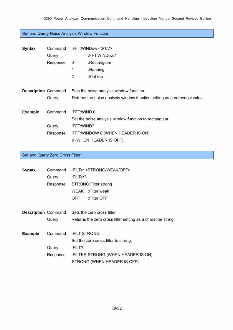
3390 Power Analyzer Communication Command Handling Instruction Manual Second Revised Edition
49/92
Set and Query Noise Analysis Window Function
Syntax Command :FFT:WINDow <0/1/2>
Query :FFT:WINDow?
Response 0 :Rectangular
1 :Hanning
2 :Flat top
Description Command Sets the noise analysis window function.
Query Returns the noise analysis window function setting as a numerical value.
Example Command :FFT:WIND 0
Set the noise analysis window function to rectangular.
Query :FFT:WIND?
Response :FFT:WINDOW 0 (WHEN HEADER IS ON)
0 (WHEN HEADER IS OFF)
Set and Query Zero Cross Filter
Syntax Command :FILTer <STRONG/WEAK/OFF>
Query :FILTer?
Response STRONG:Filter strong
WEAK :Filter weak
OFF :Filter OFF
Description Command Sets the zero cross filter.
Query Returns the zero cross filter setting as a character string.
Example Command :FILT STRONG
Set the zero cross filter to strong.
Query :FILT?
Response :FILTER STRONG (WHEN HEADER IS ON)
STRONG (WHEN HEADER IS OFF)
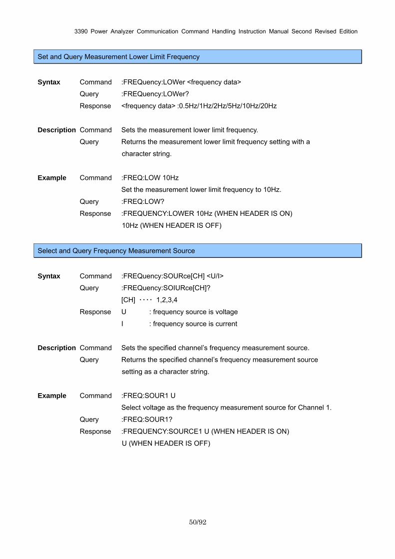
3390 Power Analyzer Communication Command Handling Instruction Manual Second Revised Edition
50/92
Set and Query Measurement Lower Limit Frequency
Syntax Command :FREQuency:LOWer <frequency data>
Query :FREQuency:LOWer?
Response <frequency data> :0.5Hz/1Hz/2Hz/5Hz/10Hz/20Hz
Description Command Sets the measurement lower limit frequency.
Query Returns the measurement lower limit frequency setting with a
character string.
Example Command :FREQ:LOW 10Hz
Set the measurement lower limit frequency to 10Hz.
Query :FREQ:LOW?
Response :FREQUENCY:LOWER 10Hz (WHEN HEADER IS ON)
10Hz (WHEN HEADER IS OFF)
Select and Query Frequency Measurement Source
Syntax Command :FREQuency:SOURce[CH] <U/I>
Query :FREQuency:SOIURce[CH]?
[CH] ・・・・ 1,2,3,4
Response U : frequency source is voltage
I : frequency source is current
Description Command Sets the specified channel’s frequency measurement source.
Query Returns the specified channel’s frequency measurement source
setting as a character string.
Example Command :FREQ:SOUR1 U
Select voltage as the frequency measurement source for Channel 1.
Query :FREQ:SOUR1?
Response :FREQUENCY:SOURCE1 U (WHEN HEADER IS ON)
U (WHEN HEADER IS OFF)
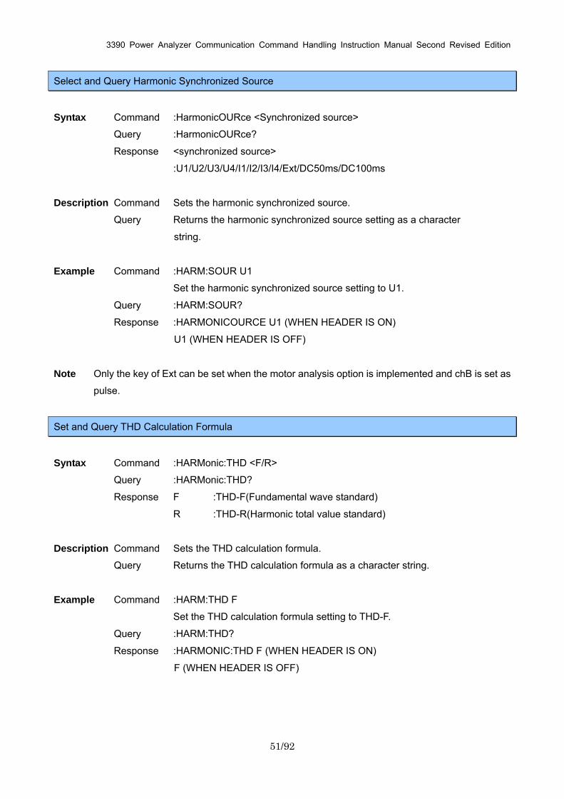
3390 Power Analyzer Communication Command Handling Instruction Manual Second Revised Edition
51/92
Select and Query Harmonic Synchronized Source
Syntax Command :HarmonicOURce <Synchronized source>
Query :HarmonicOURce?
Response <synchronized source>
:U1/U2/U3/U4/I1/I2/I3/I4/Ext/DC50ms/DC100ms
Description Command Sets the harmonic synchronized source.
Query Returns the harmonic synchronized source setting as a character
string.
Example Command :HARM:SOUR U1
Set the harmonic synchronized source setting to U1.
Query :HARM:SOUR?
Response :HARMONICOURCE U1 (WHEN HEADER IS ON)
U1 (WHEN HEADER IS OFF)
Note Only the key of Ext can be set when the motor analysis option is implemented and chB is set as
pulse.
Set and Query THD Calculation Formula
Syntax Command :HARMonic:THD <F/R>
Query :HARMonic:THD?
Response F :THD-F(Fundamental wave standard)
R :THD-R(Harmonic total value standard)
Description Command Sets the THD calculation formula.
Query Returns the THD calculation formula as a character string.
Example Command :HARM:THD F
Set the THD calculation formula setting to THD-F.
Query :HARM:THD?
Response :HARMONIC:THD F (WHEN HEADER IS ON)
F (WHEN HEADER IS OFF)
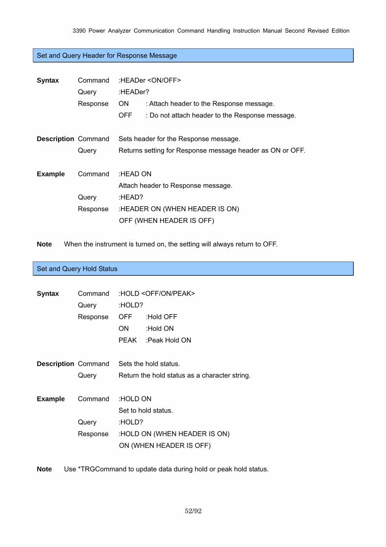
3390 Power Analyzer Communication Command Handling Instruction Manual Second Revised Edition
52/92
Set and Query Header for Response Message
Syntax Command :HEADer <ON/OFF>
Query :HEADer?
Response ON : Attach header to the Response message.
OFF : Do not attach header to the Response message.
Description Command Sets header for the Response message.
Query Returns setting for Response message header as ON or OFF.
Example Command :HEAD ON
Attach header to Response message.
Query :HEAD?
Response :HEADER ON (WHEN HEADER IS ON)
OFF (WHEN HEADER IS OFF)
Note When the instrument is turned on, the setting will always return to OFF.
Set and Query Hold Status
Syntax Command :HOLD <OFF/ON/PEAK>
Query :HOLD?
Response OFF :Hold OFF
ON :Hold ON
PEAK :Peak Hold ON
Description Command Sets the hold status.
Query Return the hold status as a character string.
Example Command :HOLD ON
Set to hold status.
Query :HOLD?
Response :HOLD ON (WHEN HEADER IS ON)
ON (WHEN HEADER IS OFF)
Note Use *TRGCommand to update data during hold or peak hold status.
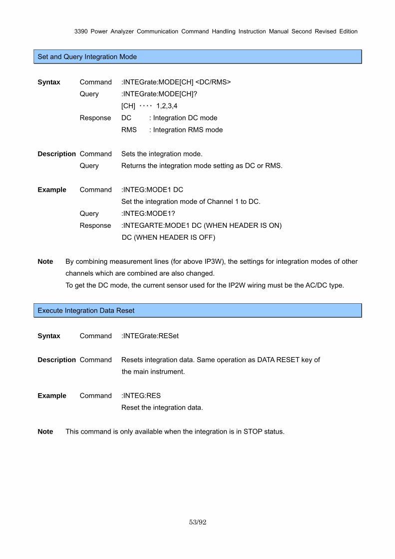
3390 Power Analyzer Communication Command Handling Instruction Manual Second Revised Edition
53/92
Set and Query Integration Mode
Syntax Command :INTEGrate:MODE[CH] <DC/RMS>
Query :INTEGrate:MODE[CH]?
[CH] ・・・・ 1,2,3,4
Response DC : Integration DC mode
RMS : Integration RMS mode
Description Command Sets the integration mode.
Query Returns the integration mode setting as DC or RMS.
Example Command :INTEG:MODE1 DC
Set the integration mode of Channel 1 to DC.
Query :INTEG:MODE1?
Response :INTEGARTE:MODE1 DC (WHEN HEADER IS ON)
DC (WHEN HEADER IS OFF)
Note By combining measurement lines (for above IP3W), the settings for integration modes of other
channels which are combined are also changed.
To get the DC mode, the current sensor used for the IP2W wiring must be the AC/DC type.
Execute Integration Data Reset
Syntax Command :INTEGrate:RESet
Description Command Resets integration data. Same operation as DATA RESET key of
the main instrument.
Example Command :INTEG:RES
Reset the integration data.
Note This command is only available when the integration is in STOP status.
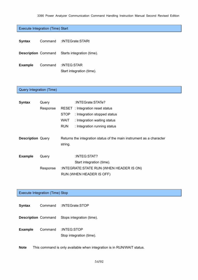
3390 Power Analyzer Communication Command Handling Instruction Manual Second Revised Edition
54/92
Execute Integration (Time) Start
Syntax Command :INTEGrate:STARt
Description Command Starts integration (time).
Example Command :INTEG:STAR
Start integration (time).
Query Integration (Time)
Syntax Query :INTEGrate:STATe?
Response RESET : Integration reset status
STOP : Integration stopped status
WAIT : Integration waiting status
RUN : Integration running status
Description Query Returns the integration status of the main instrument as a character
string.
Example Query :INTEG:STAT?
Start integration (time).
Response :INTEGRATE:STATE RUN (WHEN HEADER IS ON)
RUN (WHEN HEADER IS OFF)
Execute Integration (Time) Stop
Syntax Command :INTEGrate:STOP
Description Command Stops integration (time).
Example Command :INTEG:STOP
Stop integration (time).
Note This command is only available when integration is in RUN/WAIT status.
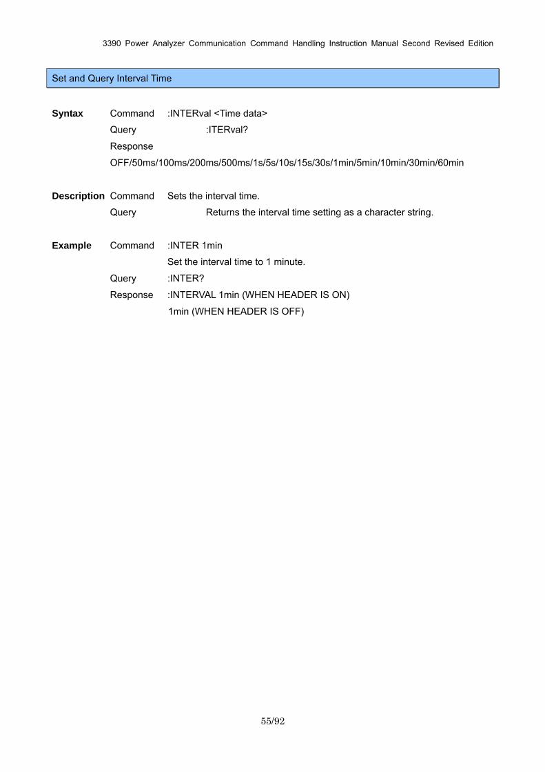
3390 Power Analyzer Communication Command Handling Instruction Manual Second Revised Edition
55/92
Set and Query Interval Time
Syntax Command :INTERval <Time data>
Query :ITERval?
Response
OFF/50ms/100ms/200ms/500ms/1s/5s/10s/15s/30s/1min/5min/10min/30min/60min
Description Command Sets the interval time.
Query Returns the interval time setting as a character string.
Example Command :INTER 1min
Set the interval time to 1 minute.
Query :INTER?
Response :INTERVAL 1min (WHEN HEADER IS ON)
1min (WHEN HEADER IS OFF)
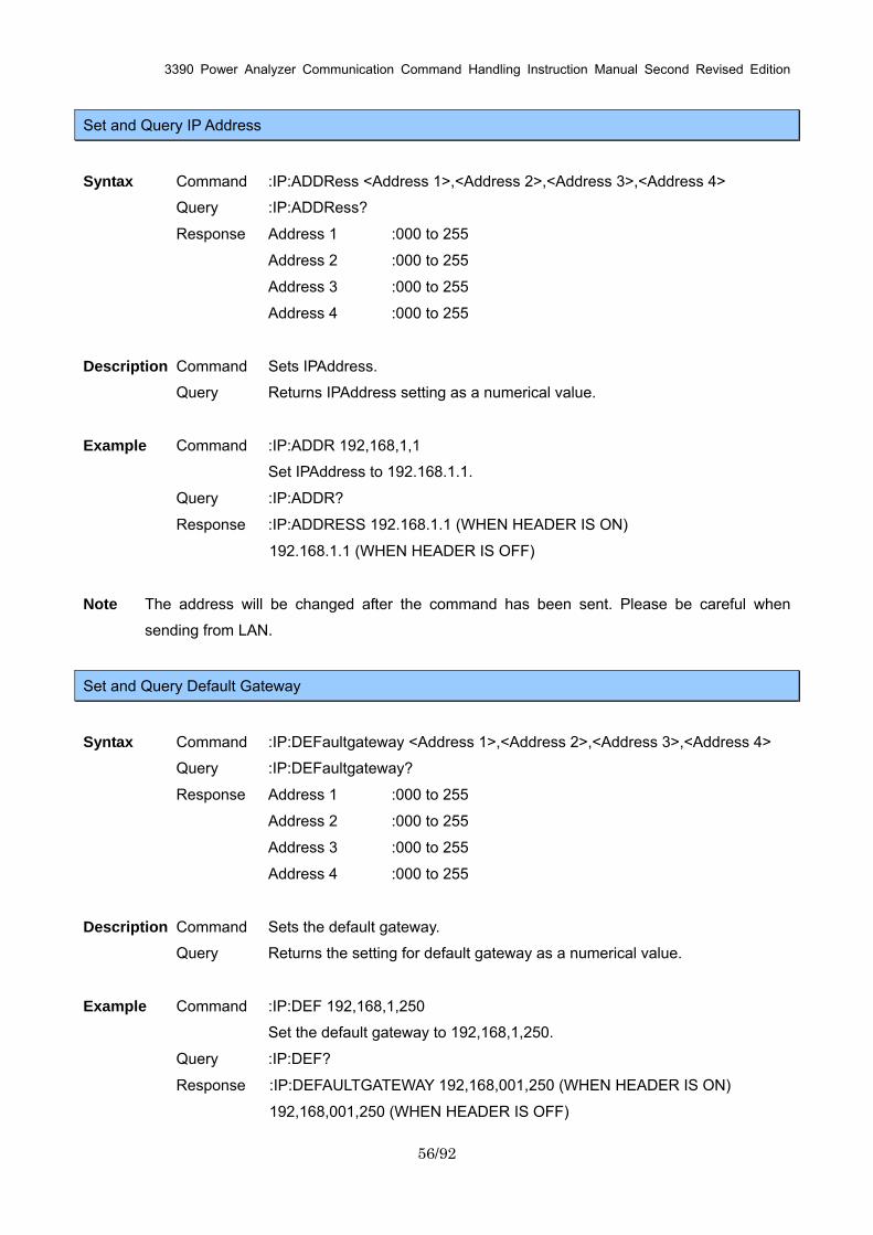
3390 Power Analyzer Communication Command Handling Instruction Manual Second Revised Edition
56/92
Set and Query IP Address
Syntax Command :IP:ADDRess <Address 1>,<Address 2>,<Address 3>,<Address 4>
Query :IP:ADDRess?
Response Address 1 :000 to 255
Address 2 :000 to 255
Address 3 :000 to 255
Address 4 :000 to 255
Description Command Sets IPAddress.
Query Returns IPAddress setting as a numerical value.
Example Command :IP:ADDR 192,168,1,1
Set IPAddress to 192.168.1.1.
Query :IP:ADDR?
Response :IP:ADDRESS 192.168.1.1 (WHEN HEADER IS ON)
192.168.1.1 (WHEN HEADER IS OFF)
Note The address will be changed after the command has been sent. Please be careful when
sending from LAN.
Set and Query Default Gateway
Syntax Command :IP:DEFaultgateway <Address 1>,<Address 2>,<Address 3>,<Address 4>
Query :IP:DEFaultgateway?
Response Address 1 :000 to 255
Address 2 :000 to 255
Address 3 :000 to 255
Address 4 :000 to 255
Description Command Sets the default gateway.
Query Returns the setting for default gateway as a numerical value.
Example Command :IP:DEF 192,168,1,250
Set the default gateway to 192,168,1,250.
Query :IP:DEF?
Response :IP:DEFAULTGATEWAY 192,168,001,250 (WHEN HEADER IS ON)
192,168,001,250 (WHEN HEADER IS OFF)
3390 Power Analyzer Communication Command Handling Instruction Manual Second Revised Edition
57/92
Set and Query Subnet Mask
Syntax Command :IP:SUBNetmask <Address 1>,<Address 2>,<Address 3>,<Address 4>
Query :IP:SUBNetmask?
Response Address 1 :000 to 255
Address 2 :000 to 255
Address 3 :000 to 255
Address 4 :000 to 255
Description Command Sets the subnet mask.
Query Returns the subnet mask setting as a numerical value.
Example Command :IP:SUBN 255,255,255,0
Set the subnet mask to 255,255,255,0.
Query :IP:SUBN?
Response :IP:SUBNETMASK 255,255,255,000 (WHEN HEADER IS ON)
255,255,255,000 (WHEN HEADER IS OFF)
Set and Query Key Lock
Syntax Command :KEYLock <ON/OFF>
Query :KEYLock?
Response ON : Turn key lock on.
OFF : Turn key lock off.
Description Command Sets the key lock ON/OFF.
Query Returns the key lock setting as ON or OFF.
Example Command :KEYL ON
Set the key lock ON.
Query :KEYL?
Response :KEYLOCK ON (WHEN HEADER IS ON)
ON (WHEN HEADER IS OFF)
3390 Power Analyzer Communication Command Handling Instruction Manual Second Revised Edition
58/92
Set and Query Main Instrument Display Language
Syntax Command :LANGuage <Language>
Query :LANGuage?
Response <Language> :JAPANESE/ENGLISH/CHINESE
Description Command Sets the display language for the main instrument.
Query Returns the display language setting for the main instrument as
a character string.
Example Command :LANG ENGLISH
Set the display language of the main instrument to English.
Query :LANG?
Response :LANGUAGE ENGLISH (WHEN HEADER IS ON)
ENGLISH (WHEN HEADER IS OFF)
Select and Query Low Pulse Filter (LPF)
Syntax Command :LPF[CH] <OFF/500Hz/5kHz/100kHz>
Query :LPF[CH]?
[CH] ・・・・ 1,2,3,4
Response <OFF/500Hz/5kHz/100kHz>
Description Command Sets the cutoff frequency for the low pulse filter (LPF).
Query Returns the setting for the cut off frequency for the low pulse filter as a
character string.
Example Command :LPF1 500Hz
Set the cutoff frequency for the low pulse filter of Channel 1 to 500Hz.
Query :LPF1?
Response :LPF1 500Hz (WHEN HEADER IS ON)
500Hz (WHEN HEADER IS OFF)
Note By combining measurement lines (for above IP3W), the settings for the low pulse filters (LPF)
of other channels which are combined are also changed.
3390 Power Analyzer Communication Command Handling Instruction Manual Second Revised Edition
59/92
Query Measurement Data
Syntax Query :MEASure? <Item 1>, <Item 2>, ....... ,<Item 31>,<Item 32> Response <Item 1>, <Item 2>, ....... ,<Item 31>,<Item 32> <Item 1 to 32> : Fundamental measurement item arbitrary within
the parameter. (Refer to 4. Fundamental Measurement Item Parameters) Description Query Item Specified Mode (with parameters) <Item> Describing any part will change it to this mode.
<Item> Create measurement data specified by this. A maximum of 32 items is possible. <Item> Can be arbitrarily specified within the fundamental measurement item parameter, but anything else that is specified will return a command error. <Item> Order is arbitrary. Creates the data in the order specified.
Item No Specified Mode (with no parameters) <Item> If not part is specified, the mode will change to this. Create measurement data of item specified under a type
of :MEASure:ITEM Command. The measurement data order is fixed. (Refer to the output item and order table) Status data is always attached to the beginning of the data.
Example Query :MEAS? Urms1, P1, DEG1 (Example of Item specified mode) Query the voltage RMS, effective power value, and power phase angle of Channel 1.
Response Urms1 151.63E+00,P1 5.74E+00,DEG1 83.80E+00 (WHEN HEADER IS ON) 151.78E+00,5.58E+00,84.00E+00 (WHEN HEADER IS OFF)
Measurement data format
General Measurement value
6 digits including digits after the decimal point Index 2 digits
Integration Value 7 digits including digits after the decimal point Index 2 digits
Time Year/Month/Date Hour/Minute/Second Elapsed time Elapsed Time (ms)
Error Input over +9999, 9E + 99 Note Controls whether to omit the + at the beginning of the fraction and the preceding 0, under
the :TRNSmit:COLumnCommand. If nothing is specified, the beginning of the fraction and the preceding 0 will be omitted (:TRNSmit:COLumn 1)
3390 Power Analyzer Communication Command Handling Instruction Manual Second Revised Edition
60/92
Query Harmonic Measurement Data
Syntax Query :MEASure:HARMonic?
Description Query Creates measurement data of item specified under a type
of :MEASure:ITEM Command.
The measurement data order is fixed. (Refer to the output item and order
table)
Statusdata is always attached to the beginning of the data.
Example Query :MEAS:HARM?
Query the harmonic measurement data.
Response Status F0000000,HU1L001 90.45E+00,HU1D001 100.00E+00
,HP1L001 0.0043E+03,HU1L003 0.20E+00,HU1D003 0.22E+00
,HP1L003 -0.0000E+03 (WHEN HEADER IS ON)
F0000000,90.45E+00,100.00E+00,0.0043E+03,0.20E+00,0.22E+00
,-0.0000E+03 (WHEN HEADER IS OFF)
Measurement data format
General
measurement data
6 digits including digits after the decimal point
Index 2 digits
Error Input over +9999, 9E + 99
Note Controls whether to omit the + at the beginning of the fraction and the preceding 0, under
the :TRNSmit:COLumnCommand.
If nothing is specified, the beginning of the fraction and the preceding 0 will be omitted
(:TRNSmit:COLumn 1)
3390 Power Analyzer Communication Command Handling Instruction Manual Second Revised Edition
61/92
Query Noise Measurement Value Data
Syntax Query :MEASure:NOISepeak? Description Query Returns the voltage of the noise measurement value, the
frequencies of the top 10 pole current values and numerical values. The measurement data order is fixed. (Refer to the output item and order table) First, ten voltage followed by 10 current values will be outputted from the top in the order of frequency and numerical value.
Example Query :MEAS:NOIS? Query the noise measurement’s voltage and current.
Query Voltage Noise Measurement Value Data
Syntax Query :MEASure:NOISepeak:U? Description Query Returns the frequencies of the top 10 pole voltage values and numerical
values. The measurement data order is fixed. (Refer to the output item and order table) The top 10 voltage values will be outputted from the top in the order of frequency and numerical value (20 data).
Example Query :MEAS:NOIS:U? Query the noise measurement value.
Query Current Noise Measurement Value Data
Syntax Query :MEASure:NOISepeak:I? Description Query Returns the frequencies of the top 10 pole current values and numerical
values. The measurement data order is fixed. (Refer to the output item and order table) The top 10 current values will be outputted from the top in the order of frequency and numerical value (20 data).
Example Query :MEAS:NOIS:I? Query the noise measurement value of the current. Note Controls whether to omit the + at the beginning of the fraction and the preceding 0, under
the :TRNSmit:COLumnCommand.
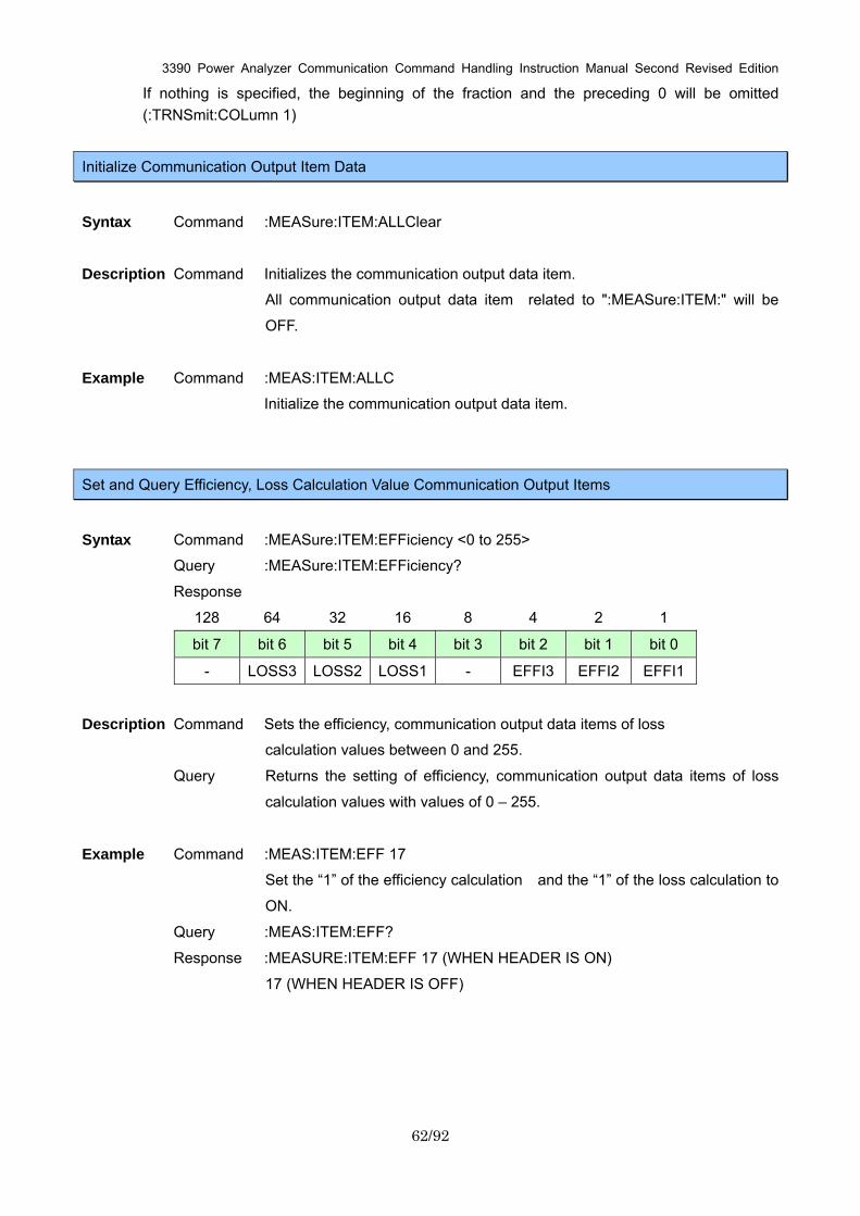
3390 Power Analyzer Communication Command Handling Instruction Manual Second Revised Edition
62/92
If nothing is specified, the beginning of the fraction and the preceding 0 will be omitted (:TRNSmit:COLumn 1)
Initialize Communication Output Item Data
Syntax Command :MEASure:ITEM:ALLClear
Description Command Initializes the communication output data item.
All communication output data item related to ":MEASure:ITEM:" will be
OFF.
Example Command :MEAS:ITEM:ALLC
Initialize the communication output data item.
Set and Query Efficiency, Loss Calculation Value Communication Output Items
Syntax Command :MEASure:ITEM:EFFiciency <0 to 255>
Query :MEASure:ITEM:EFFiciency?
Response
128 64 32 16 8 4 2 1
bit 7 bit 6 bit 5 bit 4 bit 3 bit 2 bit 1 bit 0
- LOSS3 LOSS2 LOSS1 - EFFI3 EFFI2 EFFI1
Description Command Sets the efficiency, communication output data items of loss
calculation values between 0 and 255.
Query Returns the setting of efficiency, communication output data items of loss
calculation values with values of 0 – 255.
Example Command :MEAS:ITEM:EFF 17
Set the “1” of the efficiency calculation and the “1” of the loss calculation to
ON.
Query :MEAS:ITEM:EFF?
Response :MEASURE:ITEM:EFF 17 (WHEN HEADER IS ON)
17 (WHEN HEADER IS OFF)
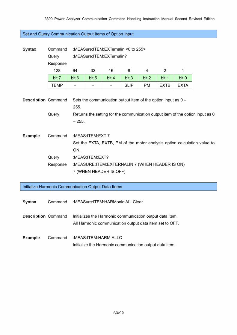
3390 Power Analyzer Communication Command Handling Instruction Manual Second Revised Edition
63/92
Set and Query Communication Output Items of Option Input
Syntax Command :MEASure:ITEM:EXTernalin <0 to 255>
Query :MEASure:ITEM:EXTernalin?
Response
128 64 32 16 8 4 2 1
bit 7 bit 6 bit 5 bit 4 bit 3 bit 2 bit 1 bit 0
TEMP - - - SLIP PM EXTB EXTA
Description Command Sets the communication output item of the option input as 0 –
255.
Query Returns the setting for the communication output item of the option input as 0
– 255.
Example Command :MEAS:ITEM:EXT 7
Set the EXTA, EXTB, PM of the motor analysis option calculation value to
ON.
Query :MEAS:ITEM:EXT?
Response :MEASURE:ITEM:EXTERNALIN 7 (WHEN HEADER IS ON)
7 (WHEN HEADER IS OFF)
Initialize Harmonic Communication Output Data Items
Syntax Command :MEASure:ITEM:HARMonic:ALLClear
Description Command Initializes the Harmonic communication output data item.
All Harmonic communication output data item set to OFF.
Example Command :MEAS:ITEM:HARM:ALLC
Initialize the Harmonic communication output data item.
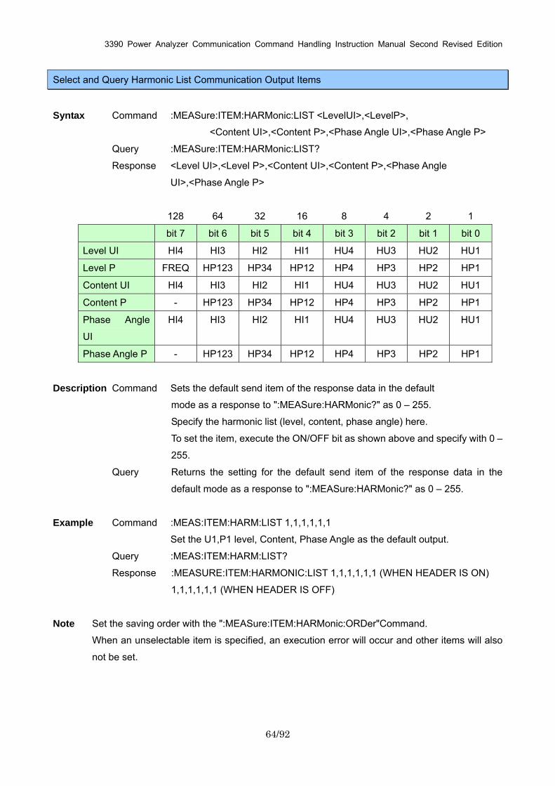
3390 Power Analyzer Communication Command Handling Instruction Manual Second Revised Edition
64/92
Select and Query Harmonic List Communication Output Items
Syntax Command :MEASure:ITEM:HARMonic:LIST <LevelUI>,<LevelP>,
<Content UI>,<Content P>,<Phase Angle UI>,<Phase Angle P>
Query :MEASure:ITEM:HARMonic:LIST?
Response <Level UI>,<Level P>,<Content UI>,<Content P>,<Phase Angle
UI>,<Phase Angle P>
128 64 32 16 8 4 2 1
bit 7 bit 6 bit 5 bit 4 bit 3 bit 2 bit 1 bit 0
Level UI HI4 HI3 HI2 HI1 HU4 HU3 HU2 HU1
Level P FREQ HP123 HP34 HP12 HP4 HP3 HP2 HP1
Content UI HI4 HI3 HI2 HI1 HU4 HU3 HU2 HU1
Content P - HP123 HP34 HP12 HP4 HP3 HP2 HP1
Phase Angle
UI
HI4 HI3 HI2 HI1 HU4 HU3 HU2 HU1
Phase Angle P - HP123 HP34 HP12 HP4 HP3 HP2 HP1
Description Command Sets the default send item of the response data in the default
mode as a response to ":MEASure:HARMonic?" as 0 – 255.
Specify the harmonic list (level, content, phase angle) here.
To set the item, execute the ON/OFF bit as shown above and specify with 0 –
255.
Query Returns the setting for the default send item of the response data in the
default mode as a response to ":MEASure:HARMonic?" as 0 – 255.
Example Command :MEAS:ITEM:HARM:LIST 1,1,1,1,1,1
Set the U1,P1 level, Content, Phase Angle as the default output.
Query :MEAS:ITEM:HARM:LIST?
Response :MEASURE:ITEM:HARMONIC:LIST 1,1,1,1,1,1 (WHEN HEADER IS ON)
1,1,1,1,1,1 (WHEN HEADER IS OFF)
Note Set the saving order with the ":MEASure:ITEM:HARMonic:ORDer"Command.
When an unselectable item is specified, an execution error will occur and other items will also
not be set.
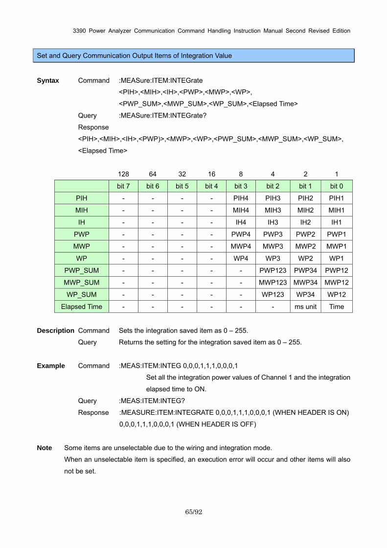
3390 Power Analyzer Communication Command Handling Instruction Manual Second Revised Edition
65/92
Set and Query Communication Output Items of Integration Value
Syntax Command :MEASure:ITEM:INTEGrate
<PIH>,<MIH>,<IH>,<PWP>,<MWP>,<WP>,
<PWP_SUM>,<MWP_SUM>,<WP_SUM>,<Elapsed Time>
Query :MEASure:ITEM:INTEGrate?
Response
<PIH>,<MIH>,<IH>,<PWP)>,<MWP>,<WP>,<PWP_SUM>,<MWP_SUM>,<WP_SUM>,
<Elapsed Time>
128 64 32 16 8 4 2 1
bit 7 bit 6 bit 5 bit 4 bit 3 bit 2 bit 1 bit 0
PIH - - - - PIH4 PIH3 PIH2 PIH1
MIH - - - - MIH4 MIH3 MIH2 MIH1
IH - - - - IH4 IH3 IH2 IH1
PWP - - - - PWP4 PWP3 PWP2 PWP1
MWP - - - - MWP4 MWP3 MWP2 MWP1
WP - - - - WP4 WP3 WP2 WP1
PWP_SUM - - - - - PWP123 PWP34 PWP12
MWP_SUM - - - - - MWP123 MWP34 MWP12
WP_SUM - - - - - WP123 WP34 WP12
Elapsed Time - - - - - - ms unit Time
Description Command Sets the integration saved item as 0 – 255.
Query Returns the setting for the integration saved item as 0 – 255.
Example Command :MEAS:ITEM:INTEG 0,0,0,1,1,1,0,0,0,1
Set all the integration power values of Channel 1 and the integration
elapsed time to ON.
Query :MEAS:ITEM:INTEG?
Response :MEASURE:ITEM:INTEGRATE 0,0,0,1,1,1,0,0,0,1 (WHEN HEADER IS ON)
0,0,0,1,1,1,0,0,0,1 (WHEN HEADER IS OFF)
Note Some items are unselectable due to the wiring and integration mode.
When an unselectable item is specified, an execution error will occur and other items will also
not be set.
3390 Power Analyzer Communication Command Handling Instruction Manual Second Revised Edition
66/92
Set and Query Output Order of Harmonic Data Communication Output
Syntax Command :MEASure:ITEM:HARMonic:ORDer <Lower limit order>,<Upper limit
order>, <ODD/EVEN/ALL>
Query :MEASure:ITEM:HARMonic:ORDer?
Response Lower limit order (NR1) :0 to 100
Upper limit order (NR1) :0 to100
ODD : Odd-number order only
EVEN : Even-number order only
ALL : All orders
Description Command Sets the default send item of the response data in the default mode as a
response to ":MEASure:HARMonic?" as 0 – 255.
Use in a combination with ":MEASure:ITEM:HARMonic:LIST"Command.
Query Returns the setting for the default send item of the response data in
the default mode as a response to ":MEASure:HARMonic?" as numerical
values or character strings.
Example Command :MEAS:ITEM:HARM:ORD 1,15,ODD
Set the odd-number order from 1 – 15 to the default output.
Query :MEAS:ITEM:HARM:ORD?
Response :MEASURE:HARMONIC:ORDER 1,15,ODD (WHEN HEADER IS ON)
1,15,ODD (WHEN HEADER IS OFF)
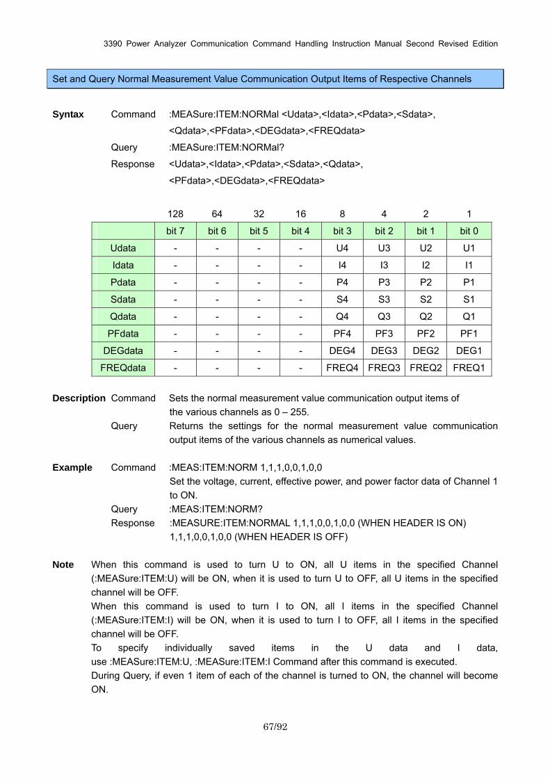
3390 Power Analyzer Communication Command Handling Instruction Manual Second Revised Edition
67/92
Set and Query Normal Measurement Value Communication Output Items of Respective Channels
Syntax Command :MEASure:ITEM:NORMal <Udata>,<Idata>,<Pdata>,<Sdata>,
<Qdata>,<PFdata>,<DEGdata>,<FREQdata>
Query :MEASure:ITEM:NORMal?
Response <Udata>,<Idata>,<Pdata>,<Sdata>,<Qdata>,
<PFdata>,<DEGdata>,<FREQdata>
128 64 32 16 8 4 2 1
bit 7 bit 6 bit 5 bit 4 bit 3 bit 2 bit 1 bit 0
Udata - - - - U4 U3 U2 U1
Idata - - - - I4 I3 I2 I1
Pdata - - - - P4 P3 P2 P1
Sdata - - - - S4 S3 S2 S1
Qdata - - - - Q4 Q3 Q2 Q1
PFdata - - - - PF4 PF3 PF2 PF1
DEGdata - - - - DEG4 DEG3 DEG2 DEG1
FREQdata - - - - FREQ4 FREQ3 FREQ2 FREQ1
Description Command Sets the normal measurement value communication output items of
the various channels as 0 – 255. Query Returns the settings for the normal measurement value communication
output items of the various channels as numerical values. Example Command :MEAS:ITEM:NORM 1,1,1,0,0,1,0,0
Set the voltage, current, effective power, and power factor data of Channel 1 to ON.
Query :MEAS:ITEM:NORM? Response :MEASURE:ITEM:NORMAL 1,1,1,0,0,1,0,0 (WHEN HEADER IS ON)
1,1,1,0,0,1,0,0 (WHEN HEADER IS OFF)
Note When this command is used to turn U to ON, all U items in the specified Channel (:MEASure:ITEM:U) will be ON, when it is used to turn U to OFF, all U items in the specified channel will be OFF. When this command is used to turn I to ON, all I items in the specified Channel (:MEASure:ITEM:I) will be ON, when it is used to turn I to OFF, all I items in the specified channel will be OFF. To specify individually saved items in the U data and I data, use :MEASure:ITEM:U, :MEASure:ITEM:I Command after this command is executed. During Query, if even 1 item of each of the channel is turned to ON, the channel will become ON.
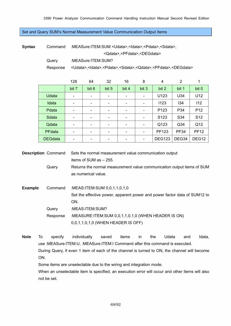
3390 Power Analyzer Communication Command Handling Instruction Manual Second Revised Edition
68/92
Set and Query SUM’s Normal Measurement Value Communication Output Items
Syntax Command :MEASure:ITEM:SUM <Udata>,<Idata>,<Pdata>,<Sdata>,
<Qdata>,<PFdata>,<DEGdata>
Query :MEASure:ITEM:SUM?
Response <Udata>,<Idata>,<Pdata>,<Sdata>,<Qdata>,<PFdata>,<DEGdata>
128 64 32 16 8 4 2 1
bit 7 bit 6 bit 5 bit 4 bit 3 bit 2 bit 1 bit 0
Udata - - - - - U123 U34 U12
Idata - - - - - I123 I34 I12
Pdata - - - - - P123 P34 P12
Sdata - - - - - S123 S34 S12
Qdata - - - - - Q123 Q34 Q12
PFdata - - - - - PF123 PF34 PF12
DEGdata - - - - - DEG123 DEG34 DEG12
Description Command Sets the normal measurement value communication output
items of SUM as – 255.
Query Returns the normal measurement value communication output items of SUM
as numerical value.
Example Command :MEAS:ITEM:SUM 0,0,1,1,0,1,0
Set the effective power, apparent power and power factor data of SUM12 to
ON.
Query :MEAS:ITEM:SUM?
Response :MEASURE:ITEM:SUM 0,0,1,1,0,1,0 (WHEN HEADER IS ON)
0,0,1,1,0,1,0 (WHEN HEADER IS OFF)
Note To specify individually saved items in the Udata and Idata,
use :MEASure:ITEM:U, :MEASure:ITEM:I Command after this command is executed.
During Query, if even 1 item of each of the channel is turned to ON, the channel will become
ON.
Some items are unselectable due to the wiring and integration mode.
When an unselectable item is specified, an execution error will occur and other items will also
not be set.
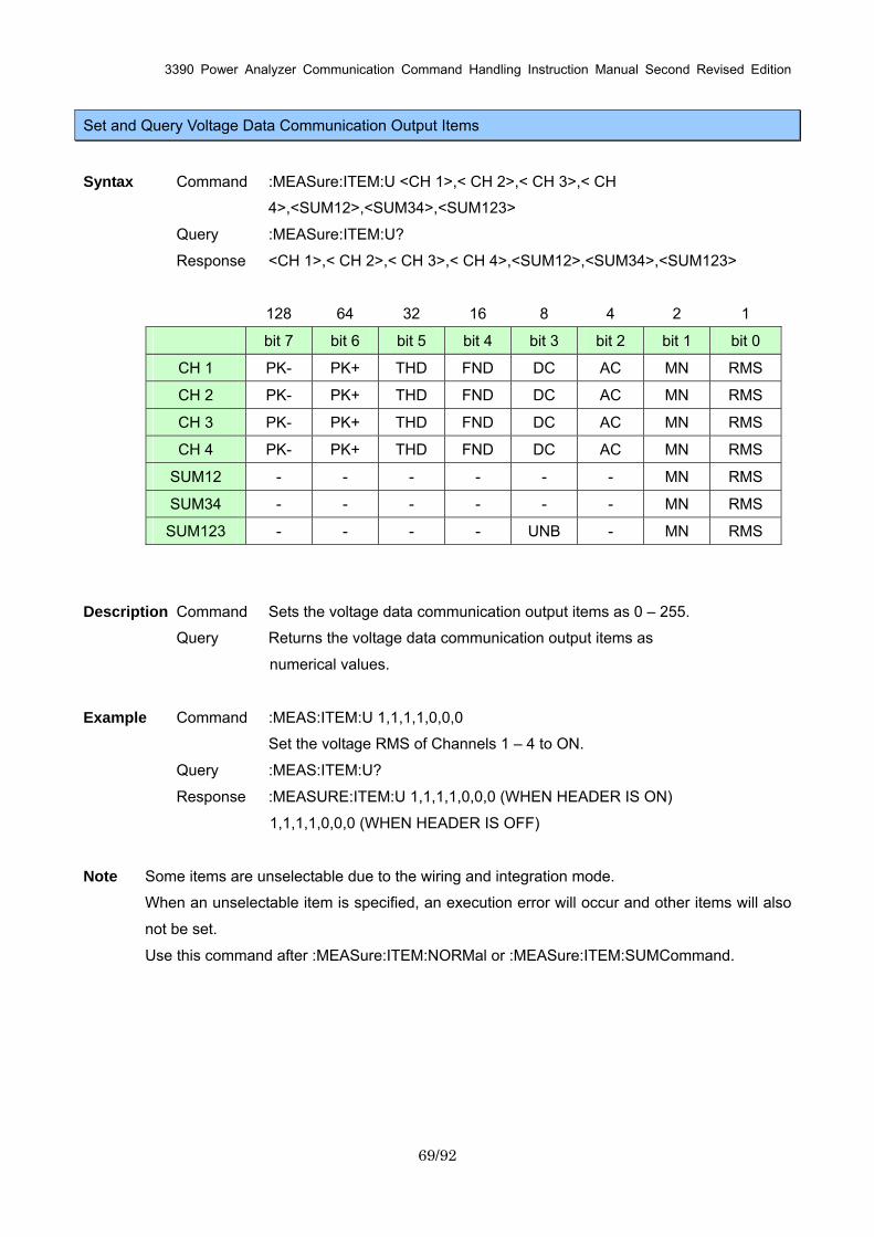
3390 Power Analyzer Communication Command Handling Instruction Manual Second Revised Edition
69/92
Set and Query Voltage Data Communication Output Items
Syntax Command :MEASure:ITEM:U <CH 1>,< CH 2>,< CH 3>,< CH
4>,<SUM12>,<SUM34>,<SUM123>
Query :MEASure:ITEM:U?
Response <CH 1>,< CH 2>,< CH 3>,< CH 4>,<SUM12>,<SUM34>,<SUM123>
128 64 32 16 8 4 2 1
bit 7 bit 6 bit 5 bit 4 bit 3 bit 2 bit 1 bit 0
CH 1 PK- PK+ THD FND DC AC MN RMS
CH 2 PK- PK+ THD FND DC AC MN RMS
CH 3 PK- PK+ THD FND DC AC MN RMS
CH 4 PK- PK+ THD FND DC AC MN RMS
SUM12 - - - - - - MN RMS
SUM34 - - - - - - MN RMS
SUM123 - - - - UNB - MN RMS
Description Command Sets the voltage data communication output items as 0 – 255.
Query Returns the voltage data communication output items as
numerical values.
Example Command :MEAS:ITEM:U 1,1,1,1,0,0,0
Set the voltage RMS of Channels 1 – 4 to ON.
Query :MEAS:ITEM:U?
Response :MEASURE:ITEM:U 1,1,1,1,0,0,0 (WHEN HEADER IS ON)
1,1,1,1,0,0,0 (WHEN HEADER IS OFF)
Note Some items are unselectable due to the wiring and integration mode.
When an unselectable item is specified, an execution error will occur and other items will also
not be set.
Use this command after :MEASure:ITEM:NORMal or :MEASure:ITEM:SUMCommand.

3390 Power Analyzer Communication Command Handling Instruction Manual Second Revised Edition
70/92
Set and Query Current Data Communication Output Items
Syntax Command :MEASure:ITEM:I <CH 1>,< CH 2>,< CH 3>,< CH
4>,<SUM12>,<SUM34>,<SUM123>
Query :MEASure:ITEM:I?
Response <CH 1>,< CH 2>,< CH 3>,< CH 4>,<SUM12>,<SUM34>,<SUM123>
128 64 32 16 8 4 2 1
bit 7 bit 6 bit 5 bit 4 bit 3 bit 2 bit 1 bit 0
CH 1 PK- PK+ THD FND DC AC MN RMS
CH 2 PK- PK+ THD FND DC AC MN RMS
CH 3 PK- PK+ THD FND DC AC MN RMS
CH 4 PK- PK+ THD FND DC AC MN RMS
SUM12 - - - - - - MN RMS
SUM34 - - - - - - MN RMS
SUM123 - - - - UNB - MN RMS
Description Command Sets the current data communication output items as 0 – 255.
Query Returns the current data communication output items as
numerical values.
Example Command :MEAS:ITEM:I 3,3,3,3,0,0,0
Set the current RMS and MEANData of Channels 1 – 4 to ON.
Query :MEAS:ITEM:I?
Response :MEASURE:ITEM:I 3,3,3,3,0,0,0 (WHEN HEADER IS ON)
3,3,3,3,0,0,0 (WHEN HEADER IS OFF)
Note Some items are unselectable due to the wiring and integration mode.
When an unselectable item is specified, an execution error will occur and other items will also
not be set.
Use this command after :MEASure:ITEM:NORMal or :MEASure:ITEM:SUMCommand.
3390 Power Analyzer Communication Command Handling Instruction Manual Second Revised Edition
71/92
Query Existence of USB Memory
Syntax Query :MEMory:EXISt?
Response Y :USB Memory
N :No USB Memory
Description Query Returns the existence of the USB in the main instrument as Y or
N.
Example Query :MEM:EXIS?
Response :MEMORY:EXIST Y (WHEN HEADER IS ON)
Y (WHEN HEADER IS OFF)
Acquire File Name in USB Memory
Syntax Query :MEMory:FILEname? <Specified Folder Name>
< Specified Folder Name >
Acquires file name under the specified folder name.
When omitted, the file name under the root folder will be acquired.
Response <File name>, <byte count>, <file name>,<byte count>,,,,,
Continue in the <File name>, <byte count> order for as long as there are
files.
When there are no more folders, the words “NO_FILES” will be returned.
Description Query Acquires the file name under the folder specified from the USB memory.
Example Query :MEM:FILE? HI3390
Acquire and return the file name under the HI3390 folder from
the USB memory.
Response :MEMORY:FILENAME H3390001.BMP,44862,M3390000.CSV,578
(WHEN HEADER IS ON)
H3390001.BMP,44682,M3390000.CSV,578 (WHEN HEADER IS OFF)
Note Up to 90 files displayed from the start of the screen can be acquired.
When more than 90 files exist in the same folder, subsequent file names cannot be acquired.
3390 Power Analyzer Communication Command Handling Instruction Manual Second Revised Edition
72/92
Acquire Folder Name in USB Memory
Syntax Query :MEMory:FOLDername? Response <Folder name>,<Folder name>,<Folder name>,,,,, Folder names will continue for as long as there are folders. When there are no more folders, the words “NO_FOLDER” will be
returned. Description Query Acquires the folder name under the root of the USB memory. Example Query :MEM:FOLD?
Response :MEMORY:FOLDERNAME HI3390 (WHEN HEADER IS ON) HI3390 (WHEN HEADER IS OFF)
Note Up to 215 folders displayed from the start of the screen can be acquired. When more than 215 folders exist in the root, subsequent folder names cannot be acquired.
Acquire File Data in USB Memory
Syntax Query :MEMory:PICKout? <File name>,<Start position (NR1)>
,<Stop position (NR1)>,<Specified folder name> Response <Folder name>,<Start position>,<Stop position>,<Specified folder name> File name :File name to be forwarded
Start position (NRI) :Specify the acquired start position in the file with byte count
Stop position (NRI) :Specify the acquired stop position in the file with byte count
Specified Folder Name:Search for file name under the specified folder When omitted, search for the file name under the root.
Description Query Reads the specified file name under the folder from the USB Memory
from the start position to the stop position, attach STX (02) to the start and ETX (03) to the end of the data to be forwarded, and forward data.
Example Query :CARD:PICK? 02030100.CSV,1,1000,HI3390 Return the 1-100 byte data of the 02030100.CSV file under the HI3390 folder
from USB Memory. Response STX(02)HIOKI 3390・・・・・ETX(03) Note Even when the header is set as ON, headers will not attach to Response data. Specify “1” if the beginning of the file is made the start position. STX/ETX is not a ASCII Code but (02)/(03) of the Binary Data.
3390 Power Analyzer Communication Command Handling Instruction Manual Second Revised Edition
73/92
Select and Query Wiring Mode
Syntax Command :MODE <TYPE1/TYEP2/TYPE3/TYPE4/TYPE5/TYPE6/TYPE7/TYPE8>
Query :MODE?
Response TYPE1: 1P2W, 1P2W, 1P2W, 1P2W
TYPE2: 1P3W, 1P2W, 1P2W
TYPE3: 3P3W, 1P2W, 1P2W
TYPE4: 1P3W, 1P3W
TYPE5: 3P3W2M, 1P3W
TYPE6: 3P3W2M, 3P3W2M
TYPE7: 3P3W3M, 1P2W
TYPE8: 3P4W, 1P2W
Description Command Selects wiring mode, and set according to the wiring of the
various channels.
Query Sets the wiring mode and returns it as character string of TYPE.
Example Command :MODE TYPE1
Set the wiring modes of all channels to IP2W.
Query :MODE?
Response :MODE TYPE1 (WHEN HEADER IS ON)
TYPE1 (WHEN HEADER IS OFF)
Note The wiring mode setting affects many settings. Try to set it as early as possible.
To set a wiring mode for a combination of multiple channels, the current sensors of the
channels to be combined must be the same.
3390 Power Analyzer Communication Command Handling Instruction Manual Second Revised Edition
74/92
Set and Query Execution Confirmation Message
Syntax Command :RS232c:ANSWer <ON/OFF> Query :RS232c:ANSWer? Response ON: Execution Confirmation Message OFF: No Execution Confirmation Message Description Command Sets the existence of execution confirmation message.
When there is a message, response will return even when the command is being sent, and an execution confirmation message will be attached at the end of the query’s response during query. The execution confirmation message has a 3-digit “nnn” format and shows an error at the nnnth Command.
“000” is shown when there is an error. Query Returns the setting for the execution confirmation message as ON or OFF.
Example Command :RS232:ANSW ON Set the execution confirmation message to ON. Query :RS232:ANSW?
Response :RS232C:ANSWER ON;000 (WHEN HEADER IS ON) ON,000 (WHEN HEADER IS OFF)
Note The command name is RS232C, but is the same operation as when communicating with LAN or USB.
Select and Query RS232C Communication Speed
Syntax Command :RS232c:BAUD <9600bps/19600bps/38400bps>
Query :RS232c:BAUD?
Response <9600bps/19600bps/38400bps>
Description Command Sets the RS232C communication speed.
Query Returns the setting for the RS232C communication speed as a character
string.
Example Command :RS232:BAUD 19600bps
Set the RS232C communication speed to 19600bps.
Query :RS232:BAUD?
Response :RS232C:BAUD 19600 (WHEN HEADER IS ON)
19600 (WHEN HEADER IS OFF)
3390 Power Analyzer Communication Command Handling Instruction Manual Second Revised Edition
75/92
Select and Query RS232C Connection Terminal
Syntax Command :RS232c:CONNect <PC/PRINTER/THERMO>
Query :RS232c:CONNect?
Response PC : Personal Computer(OFF in the main screen)
PRINTER : Printer
THERMO : Thermometer
Description Command Sets the connection terminal of RS232C.
Query Returns the setting for the RS232C connection terminal as a character string.
Example Command :RS232:CONN PRINTER
Set the RS232C connection terminal as the printer.
Query :RS232:CONN?
Response :RS232C:CONNECT PRINTER (WHEN HEADER IS ON)
PRINTER (WHEN HEADER IS OFF)
Set and Query Automatic Saving Folder Name
Syntax Command :SAVE:AUTO:FOLDername <Folder name>
Query :SAVE:AUTO:FOLDername?
Response The folder name is a character string of up to 8 characters.
Characters that can be used are ASCII characters H’20 – H’7E (except for
" */:<>?¥|).
When “NONE” is specified in the folder name, the root will become the folder
to be saved to.
Description Command Set the folder name of the automatic saving measurement file.
Query Returns the setting for the folder name of the automatic saving
measurement file as a character string.
Example Command :SAVE:AUTO:FOLD AUTO3390
Set the folder name of the automatic saving measurement file to
"AUTO3390".
Query :SAVE:AUTO:FOLD?
Response :SAVE:AUTO:FOLDERNAME AUTO3390 (WHEN HEADER IS ON)
AUTO3390 (WHEN HEADER IS OFF)
3390 Power Analyzer Communication Command Handling Instruction Manual Second Revised Edition
76/92
Set and Query Manual Saving Folder Name
Syntax Command :SAVE:FOLDername <Folder name>
Query :SAVE:FOLDername?
Response The folder name is a character string of up to 8 characters.
Characters that can be used are ASCII characters H’20 – H’7E (except for
" */:<>?¥|).
When “NONE” is specified in the folder name, the root will become the folder
to be saved to.
Description Command Sets the folder name of the manual saving measurement file.
Query Returns the setting for the folder name of the manual automatic
saving measurement file as a character string.
Example Command :SAVE:FOLD DATA3390
Set the folder name of the manual saving measurement file to "AUTO3390".
Query :SAVE:FOLD?
Response :SAVE:FOLDERNAME DATA3390 (WHEN HEADER IS ON)
DATA3390 (WHEN HEADER IS OFF)
Select and Query Manual Saving Media Location
Syntax Command :SAVE:MEDIa <MEMORY/CARD>
Query :SAVE:MEDIa?
Response MEMORY :USB Memory
CARD :CF Card
Description Command Sets the manual saving media location
Query Returns the setting for the manual saving media location as a
Character string.
Example Command :SAVE:MEDI CARD
Set the manual saving media to the CF card.
Query :SAVE:MEDI?
Response :SAVE:MEDIA CARD (WHEN HEADER IS ON)
CARD (WHEN HEADER IS OFF)
3390 Power Analyzer Communication Command Handling Instruction Manual Second Revised Edition
77/92
Set and Query CT Ratio
Syntax Command :SCALe[CH]:CT <CTRatio> Query :SCALe[CH]:CT? [CH] ・・・・ 1,2,3,4 Response CT Ratio :0000.01 to 9999.99 Description Command Sets the CT ratio of the specified channel.
Query Returns the setting for the CT ratio of the specified channel in numerical value.
Example Command :SCAL1:CT 2.0 Set the CT ratio of Channel 1 to 2.0. Query :SCAL1:CT?
Response :SCALE1:CT 0002.00 (WHEN HEADER IS ON) 0002.00 (WHEN HEADER IS OFF)
Note The setting for CT Ratio OFF is 1.0. The Query Response for OFF is 0001.00. Settings for the other channels in the measurement line combination will also be changed. Specify the first channel in the combination channels.
Set and Query VT Ratio
Syntax Command :SCALe[CH]:VT <VT Ratio> Query :SCALe[CH]:VT? [CH] ・・・・ 1,2,3,4 Response VT Ratio :0000.01 to 9999.99 Description Command Sets the VT ratio of the specified channel.
Query Returns the setting for the VT ratio of the specified channel in numerical value.
Example Command :SCAL1:VT 10.0 Set the CT ratio of Channel 1 to 10.0. Query :SCAL1:VT?
Response :SCALE1:VT 0010.00 (WHEN HEADER IS ON) 0010.00 (WHEN HEADER IS OFF)
Note The setting for VT Ratio OFF is 1.0. The Query Response for OFF is 0001.00. Settings for the other channels in the measurement line combination will also be changed. Specify the first channel in the combination channels.
3390 Power Analyzer Communication Command Handling Instruction Manual Second Revised Edition
78/92
Set and Query Synchronized Source
Syntax Command :SOURce[CH] <synchronized source>
Query :SOURce[CH]?
[CH] ・・・・ 1,2,3,4
Response <synchronized source> :U1/U2/U3/U4/I1/I2/I3/I4/Ext/DC50ms/DC100ms
Description Command Sets the synchronized source of the specified channel.
Query Returns the setting for the synchronized source of the specified
channel as a character string.
Example Command :SOUR1 U1
Set the synchronized source of Channel 1 to U1.
Query :SOUR1?
Response :SOURCE1 U1 (WHEN HEADER IS ON)
U1 (WHEN HEADER IS OFF)
Note Settings for the other channels in the measurement line combination will also be changed.
Only the key of Ext can be set when the motor analysis option is implemented and chB is set as
pulse.
Select and Query Actual Time ON/OFF
Syntax Command :STIMe:CONTrol <ON/OFF>
Query :STIMe:CONTrol?
Response ON : Actual Time ON
OFF : Actual Time OFF
Description Command Sets the actual time ON/OFF.
Query Returns the setting for actual time as ON or OFF.
Example Command :STIM:CONT ON
Set the actual time to ON.
Query :STIM:CONT?
Response :STIME:CONTROL ON (WHEN HEADER IS ON)
ON (WHEN HEADER IS OFF)
3390 Power Analyzer Communication Command Handling Instruction Manual Second Revised Edition
79/92
Set and Query Actual Time Start Time
Syntax Command :STIMe:STARttime <Year>,<Month>,<Date>,<Hour>,<Minute>
Query :STIMe:STARttime?
Response Year data:2000 to 2079 (can be set 00 - 79)
Month data:01 to 12
Date data:01 to 31
Hour data:00 to 23
Minute data:00 to 59
Description Command Sets the actual time start time.
Query Returns the time setting of the actual start time as numerical values of year,
month, date, hour and minute.
Example Command :STIM:STAR 08,12,25,12,00
Set the actual time start time as 2008 Dec 25th 12:0
Query :STIM:STAR?
Response :STIME:STARTTIME 2008,12,25,12,00 (WHEN HEADER IS ON)
2008,12,25,12,00 (WHEN HEADER IS OFF)
Note The instrument can interpret days of the month as well as leap years, so specifying an
improbable date will lead to an error.
When a time after the stop time is set, the stop time will be set one minute after the start time.
3390 Power Analyzer Communication Command Handling Instruction Manual Second Revised Edition
80/92
Set and Query Actual Time Stop Time
Syntax Command :STIMe:STOPtime <Year>,<Month>,<Date>,<Hour>,<Minute>
Query :STIMe:STOPtime?
Response Year data:2000 to 2079 (can be set 00 - 79)
Month data:01 to 12
Date data:01 to 31
Hour data:00 to 23
Minute data:00 to 59
Description Command Sets the actual time stop time.
Query Returns the time setting of the actual stop time as numerical values of year,
month, date, hour and minute.
Example Command :STIM:STOP 08,12,25,12,00
Set the actual time stop time as 2008 Dec 25th 12:0
Query :STIM:STOP?
Response :STIME:STOPTIME 2008,12,30,8,30 (WHEN HEADER IS ON)
2008,12,30,8,30 (WHEN HEADER IS OFF)
Note The instrument can interpret days of the month as well as leap years, so specifying an
improbable date will lead to an error.
When a time before the start time is set, an execution error will occur.
3390 Power Analyzer Communication Command Handling Instruction Manual Second Revised Edition
81/92
Select and Query Master/Slave of Synchronized Control Master
Syntax Command :SYNC:CONTrol <MASTER/SLAVE>
Query :SYNC:CONTrol?
Response MASTER : Master
SLAVE : Slave
Description Command Sets the master and slave of synchronized control.
Query Returns the settings of master and slave of synchronized
controls MASTER or SLAVE.
Example Command :SYNC:CONT MASTER
Set the master of synchronized control.
Query :SYNC:CONT?
Response :SYNC:CONTROL MASTER (WHEN HEADER IS ON)
MASTER (WHEN HEADER IS OFF)
Set and Query Synchronized Event Items
Syntax Command :SYNC:EVENtitem <HOLD/SAVE/COPY>
Query :SYNC:EVENtitem?
Response HOLD : Hold
SAVE : Manual Save
COPY : Screen Copy
Description Command Set the synchronized events during the synchronized control.
Query Returns the synchronized events during the synchronized control as
character strings.
Example Command :SYNC:EVEN HOLD
Set the synchronized event as hold.
Query :SYNC:EVEN?
Response :SYNC:EVENTITEM HOLD (WHEN HEADER IS ON)
HOLD (WHEN HEADER IS OFF)
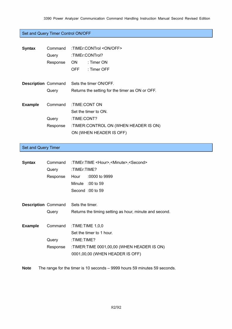
3390 Power Analyzer Communication Command Handling Instruction Manual Second Revised Edition
82/92
Set and Query Timer Control ON/OFF
Syntax Command :TIMEr:CONTrol <ON/OFF>
Query :TIMEr:CONTrol?
Response ON : Timer ON
OFF : Timer OFF
Description Command Sets the timer ON/OFF.
Query Returns the setting for the timer as ON or OFF.
Example Command :TIME:CONT ON
Set the timer to ON.
Query :TIME:CONT?
Response :TIMER:CONTROL ON (WHEN HEADER IS ON)
ON (WHEN HEADER IS OFF)
Set and Query Timer
Syntax Command :TIMEr:TIME <Hour>,<Minute>,<Second>
Query :TIMEr:TIME?
Response Hour :0000 to 9999
Minute :00 to 59
Second :00 to 59
Description Command Sets the timer.
Query Returns the timing setting as hour, minute and second.
Example Command :TIME:TIME 1,0,0
Set the timer to 1 hour.
Query :TIME:TIME?
Response :TIMER:TIME 0001,00,00 (WHEN HEADER IS ON)
0001,00,00 (WHEN HEADER IS OFF)
Note The range for the timer is 10 seconds – 9999 hours 59 minutes 59 seconds.
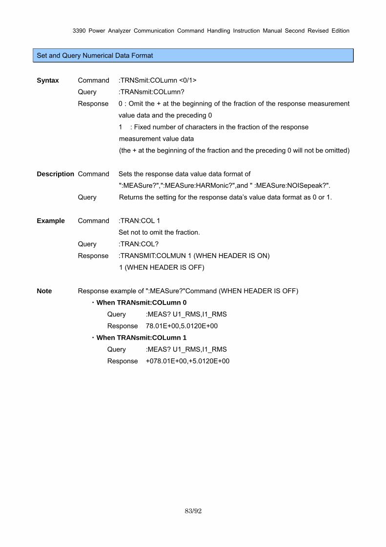
3390 Power Analyzer Communication Command Handling Instruction Manual Second Revised Edition
83/92
Set and Query Numerical Data Format
Syntax Command :TRNSmit:COLumn <0/1>
Query :TRANsmit:COLumn?
Response 0 : Omit the + at the beginning of the fraction of the response measurement
value data and the preceding 0
1 : Fixed number of characters in the fraction of the response
measurement value data
(the + at the beginning of the fraction and the preceding 0 will not be omitted)
Description Command Sets the response data value data format of
":MEASure?",":MEASure:HARMonic?",and " :MEASure:NOISepeak?".
Query Returns the setting for the response data’s value data format as 0 or 1.
Example Command :TRAN:COL 1
Set not to omit the fraction.
Query :TRAN:COL?
Response :TRANSMIT:COLMUN 1 (WHEN HEADER IS ON)
1 (WHEN HEADER IS OFF)
Note Response example of ":MEASure?"Command (WHEN HEADER IS OFF)
・When TRANsmit:COLumn 0
Query :MEAS? U1_RMS,I1_RMS
Response 78.01E+00,5.0120E+00
・When TRANsmit:COLumn 1
Query :MEAS? U1_RMS,I1_RMS
Response +078.01E+00,+5.0120E+00
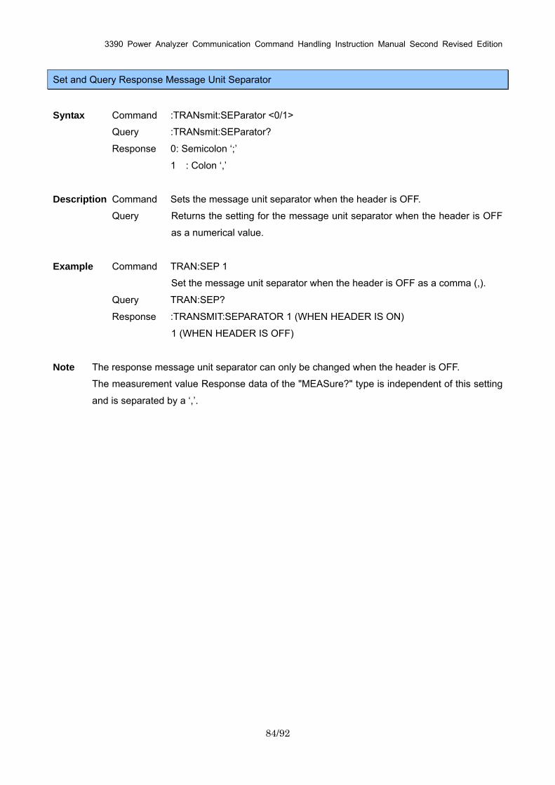
3390 Power Analyzer Communication Command Handling Instruction Manual Second Revised Edition
84/92
Set and Query Response Message Unit Separator
Syntax Command :TRANsmit:SEParator <0/1>
Query :TRANsmit:SEParator?
Response 0: Semicolon ‘;’
1 : Colon ‘,’
Description Command Sets the message unit separator when the header is OFF.
Query Returns the setting for the message unit separator when the header is OFF
as a numerical value.
Example Command TRAN:SEP 1
Set the message unit separator when the header is OFF as a comma (,).
Query TRAN:SEP?
Response :TRANSMIT:SEPARATOR 1 (WHEN HEADER IS ON)
1 (WHEN HEADER IS OFF)
Note The response message unit separator can only be changed when the header is OFF.
The measurement value Response data of the "MEASure?" type is independent of this setting
and is separated by a ‘,’.
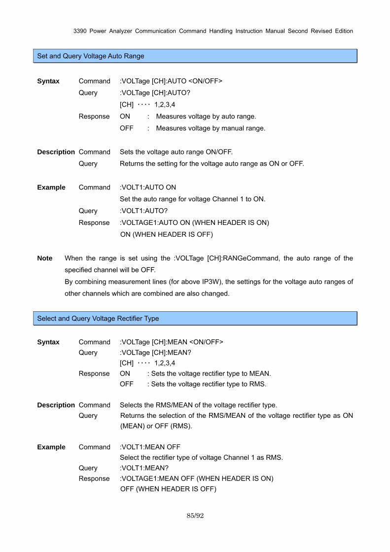
3390 Power Analyzer Communication Command Handling Instruction Manual Second Revised Edition
85/92
Set and Query Voltage Auto Range
Syntax Command :VOLTage [CH]:AUTO <ON/OFF>
Query :VOLTage [CH]:AUTO?
[CH] ・・・・ 1,2,3,4
Response ON : Measures voltage by auto range.
OFF : Measures voltage by manual range.
Description Command Sets the voltage auto range ON/OFF.
Query Returns the setting for the voltage auto range as ON or OFF.
Example Command :VOLT1:AUTO ON
Set the auto range for voltage Channel 1 to ON.
Query :VOLT1:AUTO?
Response :VOLTAGE1:AUTO ON (WHEN HEADER IS ON)
ON (WHEN HEADER IS OFF)
Note When the range is set using the :VOLTage [CH]:RANGeCommand, the auto range of the
specified channel will be OFF.
By combining measurement lines (for above IP3W), the settings for the voltage auto ranges of
other channels which are combined are also changed.
Select and Query Voltage Rectifier Type
Syntax Command :VOLTage [CH]:MEAN <ON/OFF> Query :VOLTage [CH]:MEAN? [CH] ・・・・ 1,2,3,4 Response ON : Sets the voltage rectifier type to MEAN. OFF : Sets the voltage rectifier type to RMS. Description Command Selects the RMS/MEAN of the voltage rectifier type.
Query Returns the selection of the RMS/MEAN of the voltage rectifier type as ON (MEAN) or OFF (RMS).
Example Command :VOLT1:MEAN OFF Select the rectifier type of voltage Channel 1 as RMS. Query :VOLT1:MEAN?
Response :VOLTAGE1:MEAN OFF (WHEN HEADER IS ON) OFF (WHEN HEADER IS OFF)
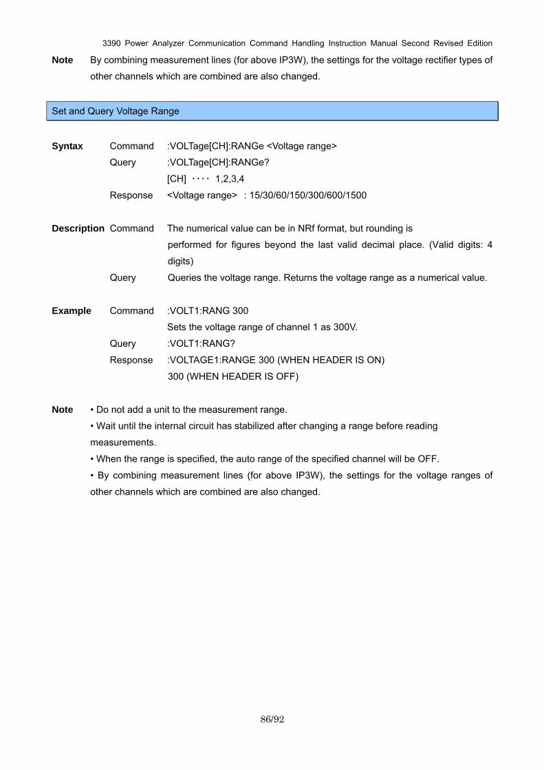
3390 Power Analyzer Communication Command Handling Instruction Manual Second Revised Edition
86/92
Note By combining measurement lines (for above IP3W), the settings for the voltage rectifier types of
other channels which are combined are also changed.
Set and Query Voltage Range
Syntax Command :VOLTage[CH]:RANGe <Voltage range>
Query :VOLTage[CH]:RANGe?
[CH] ・・・・ 1,2,3,4
Response <Voltage range> : 15/30/60/150/300/600/1500
Description Command The numerical value can be in NRf format, but rounding is
performed for figures beyond the last valid decimal place. (Valid digits: 4
digits)
Query Queries the voltage range. Returns the voltage range as a numerical value.
Example Command :VOLT1:RANG 300
Sets the voltage range of channel 1 as 300V.
Query :VOLT1:RANG?
Response :VOLTAGE1:RANGE 300 (WHEN HEADER IS ON)
300 (WHEN HEADER IS OFF)
Note • Do not add a unit to the measurement range.
• Wait until the internal circuit has stabilized after changing a range before reading
measurements.
• When the range is specified, the auto range of the specified channel will be OFF.
• By combining measurement lines (for above IP3W), the settings for the voltage ranges of
other channels which are combined are also changed.
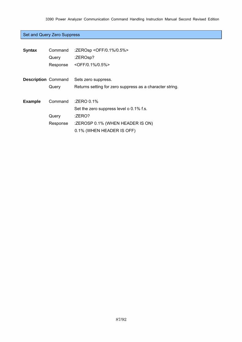
3390 Power Analyzer Communication Command Handling Instruction Manual Second Revised Edition
87/92
Set and Query Zero Suppress
Syntax Command :ZEROsp <OFF/0.1%/0.5%>
Query :ZEROsp?
Response <OFF/0.1%/0.5%>
Description Command Sets zero suppress.
Query Returns setting for zero suppress as a character string.
Example Command :ZERO 0.1%
Set the zero suppress level o 0.1% f.s.
Query :ZERO?
Response :ZEROSP 0.1% (WHEN HEADER IS ON)
0.1% (WHEN HEADER IS OFF)
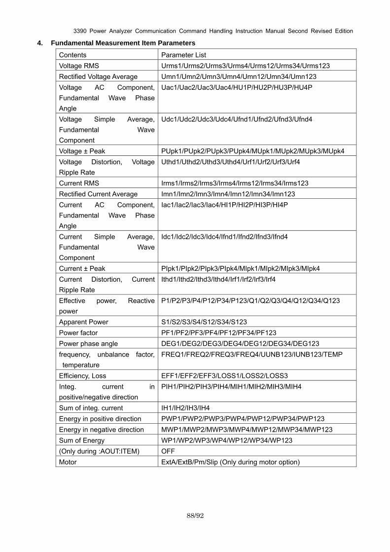
3390 Power Analyzer Communication Command Handling Instruction Manual Second Revised Edition
88/92
4. Fundamental Measurement Item Parameters
Contents Parameter List Voltage RMS Urms1/Urms2/Urms3/Urms4/Urms12/Urms34/Urms123 Rectified Voltage Average Umn1/Umn2/Umn3/Umn4/Umn12/Umn34/Umn123 Voltage AC Component, Fundamental Wave Phase Angle
Uac1/Uac2/Uac3/Uac4/HU1P/HU2P/HU3P/HU4P
Voltage Simple Average, Fundamental Wave Component
Udc1/Udc2/Udc3/Udc4/Ufnd1/Ufnd2/Ufnd3/Ufnd4
Voltage ± Peak PUpk1/PUpk2/PUpk3/PUpk4/MUpk1/MUpk2/MUpk3/MUpk4 Voltage Distortion, Voltage Ripple Rate
Uthd1/Uthd2/Uthd3/Uthd4/Urf1/Urf2/Urf3/Urf4
Current RMS Irms1/Irms2/Irms3/Irms4/Irms12/Irms34/Irms123 Rectified Current Average Imn1/Imn2/Imn3/Imn4/Imn12/Imn34/Imn123 Current AC Component, Fundamental Wave Phase Angle
Iac1/Iac2/Iac3/Iac4/HI1P/HI2P/HI3P/HI4P
Current Simple Average, Fundamental Wave Component
Idc1/Idc2/Idc3/Idc4/Ifnd1/Ifnd2/Ifnd3/Ifnd4
Current ± Peak PIpk1/PIpk2/PIpk3/PIpk4/MIpk1/MIpk2/MIpk3/MIpk4 Current Distortion, Current Ripple Rate
Ithd1/Ithd2/Ithd3/Ithd4/Irf1/Irf2/Irf3/Irf4
Effective power, Reactive power
P1/P2/P3/P4/P12/P34/P123/Q1/Q2/Q3/Q4/Q12/Q34/Q123
Apparent Power S1/S2/S3/S4/S12/S34/S123 Power factor PF1/PF2/PF3/PF4/PF12/PF34/PF123 Power phase angle DEG1/DEG2/DEG3/DEG4/DEG12/DEG34/DEG123 frequency, unbalance factor, temperature
FREQ1/FREQ2/FREQ3/FREQ4/UUNB123/IUNB123/TEMP
Efficiency, Loss EFF1/EFF2/EFF3/LOSS1/LOSS2/LOSS3 Integ. current in positive/negative direction
PIH1/PIH2/PIH3/PIH4/MIH1/MIH2/MIH3/MIH4
Sum of integ. current IH1/IH2/IH3/IH4 Energy in positive direction PWP1/PWP2/PWP3/PWP4/PWP12/PWP34/PWP123 Energy in negative direction MWP1/MWP2/MWP3/MWP4/MWP12/MWP34/MWP123 Sum of Energy WP1/WP2/WP3/WP4/WP12/WP34/WP123 (Only during :AOUT:ITEM) OFF Motor ExtA/ExtB/Pm/Slip (Only during motor option)
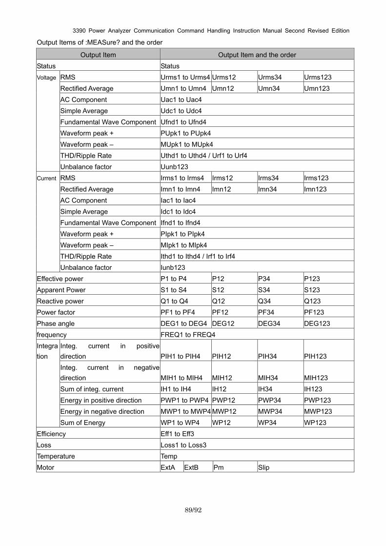
3390 Power Analyzer Communication Command Handling Instruction Manual Second Revised Edition
89/92
Output Items of :MEASure? and the order
Output Item Output Item and the order Status Status
RMS Urms1 to Urms4 Urms12 Urms34 Urms123 Rectified Average Umn1 to Umn4 Umn12 Umn34 Umn123 AC Component Uac1 to Uac4 Simple Average Udc1 to Udc4 Fundamental Wave Component Ufnd1 to Ufnd4 Waveform peak + PUpk1 to PUpk4 Waveform peak – MUpk1 to MUpk4 THD/Ripple Rate Uthd1 to Uthd4 / Urf1 to Urf4
Voltage
Unbalance factor Uunb123 RMS Irms1 to Irms4 Irms12 Irms34 Irms123 Rectified Average Imn1 to Imn4 Imn12 Imn34 Imn123 AC Component Iac1 to Iac4 Simple Average Idc1 to Idc4 Fundamental Wave Component Ifnd1 to Ifnd4 Waveform peak + PIpk1 to PIpk4 Waveform peak – MIpk1 to MIpk4 THD/Ripple Rate Ithd1 to Ithd4 / Irf1 to Irf4
Current
Unbalance factor Iunb123 Effective power P1 to P4 P12 P34 P123 Apparent Power S1 to S4 S12 S34 S123 Reactive power Q1 to Q4 Q12 Q34 Q123 Power factor PF1 to PF4 PF12 PF34 PF123 Phase angle DEG1 to DEG4 DEG12 DEG34 DEG123 frequency FREQ1 to FREQ4
Integ. current in positive direction PIH1 to PIH4 PIH12 PIH34 PIH123 Integ. current in negative direction MIH1 to MIH4 MIH12 MIH34 MIH123 Sum of integ. current IH1 to IH4 IH12 IH34 IH123 Energy in positive direction PWP1 to PWP4 PWP12 PWP34 PWP123 Energy in negative direction MWP1 to MWP4 MWP12 MWP34 MWP123
Integration
Sum of Energy WP1 to WP4 WP12 WP34 WP123 Efficiency Eff1 to Eff3 Loss Loss1 to Loss3 Temperature Temp Motor ExtA ExtB Pm Slip
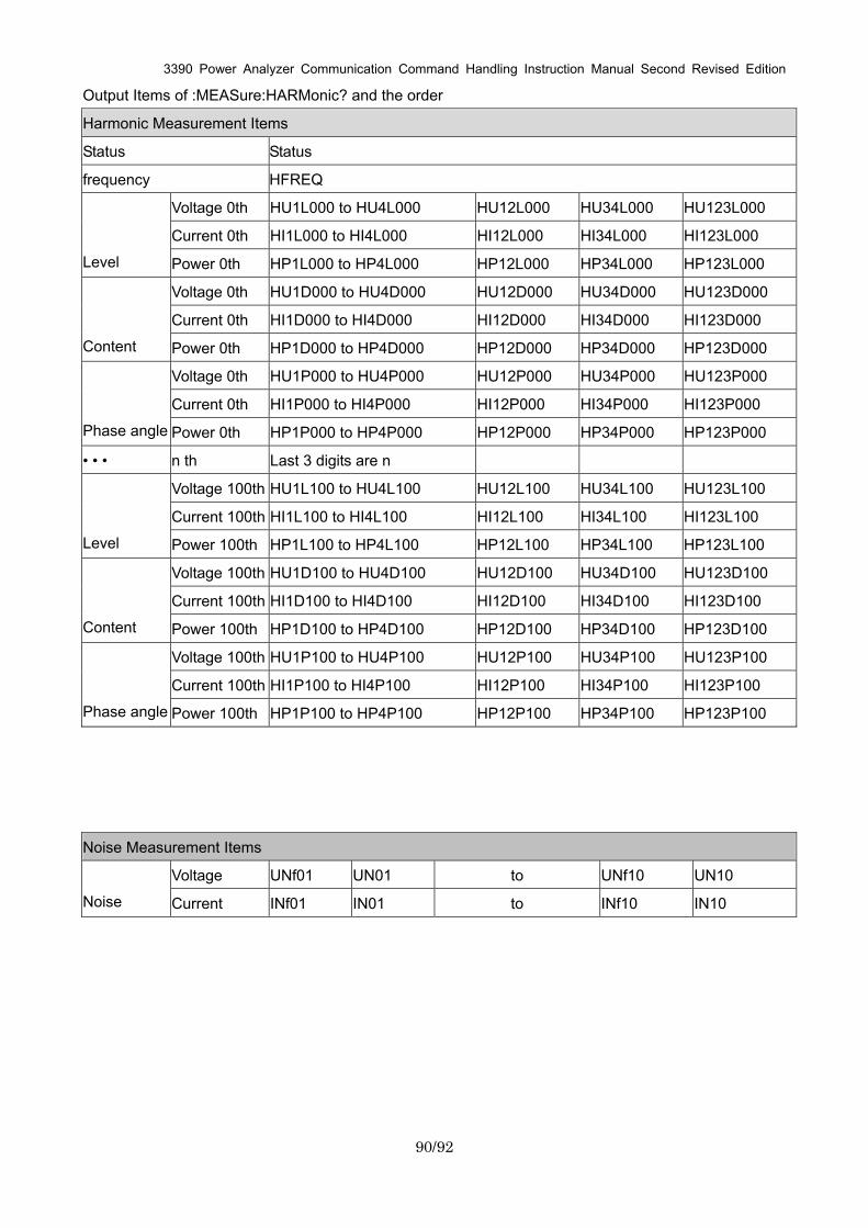
3390 Power Analyzer Communication Command Handling Instruction Manual Second Revised Edition
90/92
Output Items of :MEASure:HARMonic? and the order
Harmonic Measurement Items
Status Status
frequency HFREQ
Voltage 0th HU1L000 to HU4L000 HU12L000 HU34L000 HU123L000
Current 0th HI1L000 to HI4L000 HI12L000 HI34L000 HI123L000
Level Power 0th HP1L000 to HP4L000 HP12L000 HP34L000 HP123L000
Voltage 0th HU1D000 to HU4D000 HU12D000 HU34D000 HU123D000
Current 0th HI1D000 to HI4D000 HI12D000 HI34D000 HI123D000
Content Power 0th HP1D000 to HP4D000 HP12D000 HP34D000 HP123D000
Voltage 0th HU1P000 to HU4P000 HU12P000 HU34P000 HU123P000
Current 0th HI1P000 to HI4P000 HI12P000 HI34P000 HI123P000
Phase angle Power 0th HP1P000 to HP4P000 HP12P000 HP34P000 HP123P000
• • • n th Last 3 digits are n
Voltage 100th HU1L100 to HU4L100 HU12L100 HU34L100 HU123L100
Current 100th HI1L100 to HI4L100 HI12L100 HI34L100 HI123L100
Level Power 100th HP1L100 to HP4L100 HP12L100 HP34L100 HP123L100
Voltage 100th HU1D100 to HU4D100 HU12D100 HU34D100 HU123D100
Current 100th HI1D100 to HI4D100 HI12D100 HI34D100 HI123D100
Content Power 100th HP1D100 to HP4D100 HP12D100 HP34D100 HP123D100
Voltage 100th HU1P100 to HU4P100 HU12P100 HU34P100 HU123P100
Current 100th HI1P100 to HI4P100 HI12P100 HI34P100 HI123P100
Phase angle Power 100th HP1P100 to HP4P100 HP12P100 HP34P100 HP123P100
Noise Measurement Items
Voltage UNf01 UN01 to UNf10 UN10
Noise Current INf01 IN01 to INf10 IN10
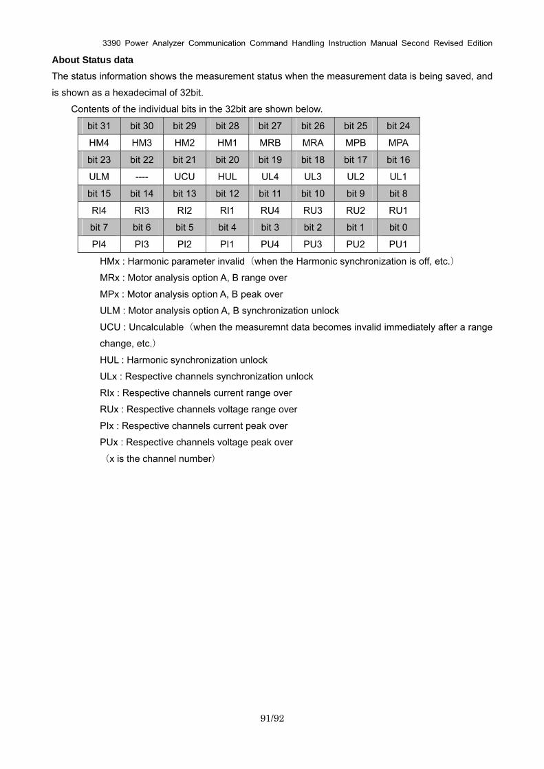
3390 Power Analyzer Communication Command Handling Instruction Manual Second Revised Edition
91/92
About Status data The status information shows the measurement status when the measurement data is being saved, and
is shown as a hexadecimal of 32bit.
Contents of the individual bits in the 32bit are shown below.
bit 31 bit 30 bit 29 bit 28 bit 27 bit 26 bit 25 bit 24
HM4 HM3 HM2 HM1 MRB MRA MPB MPA
bit 23 bit 22 bit 21 bit 20 bit 19 bit 18 bit 17 bit 16
ULM ---- UCU HUL UL4 UL3 UL2 UL1
bit 15 bit 14 bit 13 bit 12 bit 11 bit 10 bit 9 bit 8
RI4 RI3 RI2 RI1 RU4 RU3 RU2 RU1
bit 7 bit 6 bit 5 bit 4 bit 3 bit 2 bit 1 bit 0
PI4 PI3 PI2 PI1 PU4 PU3 PU2 PU1
HMx : Harmonic parameter invalid(when the Harmonic synchronization is off, etc.)
MRx : Motor analysis option A, B range over
MPx : Motor analysis option A, B peak over
ULM : Motor analysis option A, B synchronization unlock
UCU : Uncalculable(when the measuremnt data becomes invalid immediately after a range
change, etc.)
HUL : Harmonic synchronization unlock
ULx : Respective channels synchronization unlock
RIx : Respective channels current range over
RUx : Respective channels voltage range over
PIx : Respective channels current peak over
PUx : Respective channels voltage peak over
(x is the channel number)
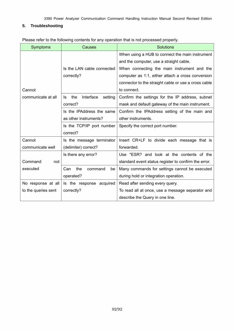
3390 Power Analyzer Communication Command Handling Instruction Manual Second Revised Edition
92/92
5. Troubleshooting
Please refer to the following contents for any operation that is not processed properly.
Symptoms Causes Solutions
Is the LAN cable connected
correctly?
When using a HUB to connect the main instrument
and the computer, use a straight cable.
When connecting the main instrument and the
computer as 1:1, either attach a cross conversion
connector to the straight cable or use a cross cable
to connect.
Is the Interface setting
correct?
Confirm the settings for the IP address, subnet
mask and default gateway of the main instrument.
Is the IPAddress the same
as other instruments?
Confirm the IPAddress setting of the main and
other instruments.
Cannot
communicate at all
Is the TCP/IP port number
correct?
Specify the correct port number.
Cannot
communicate well
Is the message terminator
(delimiter) correct?
Insert CR+LF to divide each message that is
forwarded.
Is there any error? Use *ESR? and look at the contents of the
standard event status register to confirm the error. Command not
executed Can the command be
operated?
Many commands for settings cannot be executed
during hold or integration operation.
No response at all
to the queries sent
Is the response acquired
correctly?
Read after sending every query.
To read all at once, use a message separator and
describe the Query in one line.
Related Documents


