Communication Alternatives Exploration in Model-Driven Design of Networked Embedded Systems E. Ebeid, F. Fummi, D. Quaglia Dep. of Computer Science — University of Verona, Italy Abstract—The design of next-generation networked embedded systems requires to take into account the way in which they ex- change information together to provide the desired functionality. In fact, communication patterns and network topology affect the implementation of HW and SW aspects of the nodes and their performance; for this reason the communication infrastructure is becoming a true design space dimension which requires an extension of the traditional flow. The work addresses this issue by providing 1) a model-driven design path for the specifica- tion of the communication infrastructure, 2) a methodology to manipulate the network to generate design alternatives, and 3) a technique to generate models for network simulation. New algorithms have been supported by the development of tools to manipulate network specification efficiently and to generate the simulation model automatically so that network alternatives can be explored effectively. I. I NTRODUCTION Pushed by the recent advances in communications [16], networked embedded systems are becoming the core of next- generation pervasive computing applications, e.g., in health care domain [21]. They cannot be considered as isolated elements, as done in traditional applications, but they must be designed as part of a global set of computing nodes, made of HW and SW components, interacting through the network and with the environment. To analyze such complex systems two requirements are crucial: • the network infrastructure must be specified together with other traditional aspects (i.e., HW, SW) and a platform- independent approach is preferable to focus on require- ments rather than to anticipate implementation solutions; • different communication alternatives must be explored efficiently to find the optimal solution. A platform-independent description of the network contains important communication aspects (e.g., topology, and, for each link, capacity, delay, and error rate) without referring to implementation details like medium type, and protocols description. A methodology and a tool to generate and simulate network alternatives could be the solution. This work proposes the methodology shown in Figure 1 in which: This work has been supported by the European Commission’s funded project CONTREX (611146). Fig. 1. Proposed methodology for network design space exploration. 1) the packet-based network infrastructure is described in a platform-independent way by the appropriate UML diagram and profile; HW/SW aspects are not directly described here but their presence is taken into account from a communication perspective (i.e., entities which generate and consume packets); 2) the UML description is converted into an intermediate format –supported by a formal model of computation– which allows to merge the different aspects of the whole system, both structural and behavioral; among different solutions found in literature, the Heterogeneous Intermediate Format (HIF) has been chosen since it fulfills requirements [8] and it is supported by a library, named HIFSuite [5], which simplifies tool development; 3) computational blocks are added to the HIF description to represent the behavior of the nodes which gener- ate/consume packets; such models can be provided by HIFSuite starting from a node library (e.g., in UML, VHDL, Verilog, SystemC); 4) the HIF description of the network is manipulated according to mathematical-based rules to obtain sev- eral system alternatives which are equivalent from the network perspective; computational blocks are adapted to match the network changes and new blocks are instantiated when needed; 5) for each system configuration, the corresponding sim- ulation scenario is generated; we need a simulation 2013 14th International Workshop on Microprocessor Test and Verification 1550-4093/13 $31.00 © 2013 IEEE DOI 10.1109/MTV.2013.22 45

Welcome message from author
This document is posted to help you gain knowledge. Please leave a comment to let me know what you think about it! Share it to your friends and learn new things together.
Transcript

Communication Alternatives Exploration inModel-Driven Design of Networked Embedded
Systems
E. Ebeid, F. Fummi, D. QuagliaDep. of Computer Science — University of Verona, Italy
�������������� ������������������������������
Abstract—The design of next-generation networked embeddedsystems requires to take into account the way in which they ex-change information together to provide the desired functionality.In fact, communication patterns and network topology affect theimplementation of HW and SW aspects of the nodes and theirperformance; for this reason the communication infrastructureis becoming a true design space dimension which requires anextension of the traditional flow. The work addresses this issueby providing 1) a model-driven design path for the specifica-tion of the communication infrastructure, 2) a methodology tomanipulate the network to generate design alternatives, and 3)a technique to generate models for network simulation. Newalgorithms have been supported by the development of tools tomanipulate network specification efficiently and to generate thesimulation model automatically so that network alternatives canbe explored effectively.
I. INTRODUCTION
Pushed by the recent advances in communications [16],
networked embedded systems are becoming the core of next-
generation pervasive computing applications, e.g., in health
care domain [21]. They cannot be considered as isolated
elements, as done in traditional applications, but they must
be designed as part of a global set of computing nodes, made
of HW and SW components, interacting through the network
and with the environment. To analyze such complex systems
two requirements are crucial:
• the network infrastructure must be specified together with
other traditional aspects (i.e., HW, SW) and a platform-
independent approach is preferable to focus on require-
ments rather than to anticipate implementation solutions;
• different communication alternatives must be explored
efficiently to find the optimal solution.
A platform-independent description of the network contains
important communication aspects (e.g., topology, and, for
each link, capacity, delay, and error rate) without referring
to implementation details like medium type, and protocols
description.
A methodology and a tool to generate and simulate network
alternatives could be the solution.
This work proposes the methodology shown in Figure 1 in
which:
This work has been supported by the European Commission’s fundedproject CONTREX (611146).
���� ����
����
����������
���� ����
���������� ����
������
�������
������
�������
������
������
������
������
��������
��
��������
��
!
"
#
$
%
���
��&����
���
��&����'������(
)��*�����
'������(
)��*�����
+
Fig. 1. Proposed methodology for network design space exploration.
1) the packet-based network infrastructure is described in
a platform-independent way by the appropriate UML
diagram and profile; HW/SW aspects are not directly
described here but their presence is taken into account
from a communication perspective (i.e., entities which
generate and consume packets);
2) the UML description is converted into an intermediate
format –supported by a formal model of computation–
which allows to merge the different aspects of the
whole system, both structural and behavioral; among
different solutions found in literature, the Heterogeneous
Intermediate Format (HIF) has been chosen since it
fulfills requirements [8] and it is supported by a library,
named HIFSuite [5], which simplifies tool development;
3) computational blocks are added to the HIF description
to represent the behavior of the nodes which gener-
ate/consume packets; such models can be provided by
HIFSuite starting from a node library (e.g., in UML,
VHDL, Verilog, SystemC);
4) the HIF description of the network is manipulated
according to mathematical-based rules to obtain sev-
eral system alternatives which are equivalent from the
network perspective; computational blocks are adapted
to match the network changes and new blocks are
instantiated when needed;
5) for each system configuration, the corresponding sim-
ulation scenario is generated; we need a simulation
2013 14th International Workshop on Microprocessor Test and Verification
1550-4093/13 $31.00 © 2013 IEEE
DOI 10.1109/MTV.2013.22
45
framework which allows to reproduce the behavior of
both computational and communication aspects and thus
we adopted SystemC in which computational elements
(HW and SW) are modeled in the traditional way while
the network is modeled by exploiting the SystemC
Network Simulation Library [2];
6) simulation traces and node library information are used
to evaluate the performance of each solution; for in-
stance, information on energy consumption for compu-
tation and communication, together with traces about
inter-node communications, can be used to evaluate the
overall energy consumption.
For Step (1) a UML diagram with network profile annota-
tion for network specification has been defined. For Steps (2)
and (3), a novel way to merge HW/SW/network information
has been specified. For Step (4) a manipulation algorithm to
generate network alternatives has been created. For Step (5)
an algorithm to generate simulation models from network
descriptions has been created. The proposed algorithms have
been implemented in tools for the efficient exploration of
network alternatives.
The paper is organized as follows. Section II introduces the
main background used in the work. Section III describes the
UML profile supporting the platform-independent specifica-
tion of the network. Section IV describes the conversion of
UML into HIF and the merging with HW/SW blocks models.
Section V presents the rules to generate network alternatives.
Section VI describes the generation of the SystemC exe-
cutable model of the various network alternatives. Section VII
shows experimental results while conclusions are drawn in
Section VIII.
II. BACKGROUND
A. Related work
Regarding network infrastructure modeling, different stan-
dard approaches for system description have been proposed,
e.g., UML [13] and SysML [12]. In particular, functional
modeling has been described by using models of computa-
tion [9, 8], tools like Matlab/Simulink [20] and Ptolemy [6] as
well as languages like Compositional Interchange Format [18].
Unfortunately, all these approaches do not consider the pres-
ence of a packet-based network described in a platform-
independent way. Moreover, there are a few works which
derive network simulation models from UML description. De
Miguel et al. [3] introduce UML extensions for the representa-
tion of temporal requirements and resource usage for real-time
systems. Their tools generate a simulation model for OPNET
simulator [15].
Regarding the design of network infrastructure, the investi-
gations fall in the context of the so-called network synthesis.
Various papers [22, 11, 7] describe the network synthesis
problem as an optimization problem to be solved by analytical
techniques. Even if this approach is exhaustive, it provides
solutions only in case of small networks. To find the design
solution also in case of complex networks (e.g., made of
hundreds nodes), simulation is the solution. The work in
[10] describes and simulates the behavior of communication
networks by using hybrid systems; its results indicate that
simulations using hybrid models should be preferred over
packet-level simulators in case of networks with large per-flow
bandwidth while for networks with small bandwidth, as in case
of many distributed embedded applications, the advantage is
low.
B. UML deployment diagram and profiles
Unified Modeling Language (UML) is a standardized
general-purpose modeling language created and managed by
the Object Management Group [13]. UML includes a set of
graphic notation techniques, e.g., diagrams, to create visual
models of systems. The deployment diagram represents the
physical deployment of processes (named Artifacts) on con-
tainers (named Nodes) connected by UML Communication
paths. Furthermore, other UML entities can be used in de-
ployment diagrams, e.g., Device to model HW nodes, Packageto group nodes, Dependency to connect either Artifacts or
Packages together. Deployment diagrams have a graphical
notatopn which is adopted by the most common design tools,
the Nodes appear as boxes, the Artifacts allocated to each
node appear as rectangles within the boxes. Devices appear as
nodes. Packages appear as folders. CommunicationPaths ap-
pear as continuous-lines and Dependency relationships appear
as dashed-line arrows.
Even if UML entities follow a well-defined syntax (e.g.,
a package contains nodes, a node contains artifacts), the
meaning of such entities must be defined by associating them
to the so-called Stereotypes which are similar to C-language
structs. Furthermore, new scalar DataTypes and Enumerationscan be defined and used for Stereotype fields. Stereotypes,
datatypes and enumerations are collected in the so-called
Profile. For instance, a well-known profile in the context of
embedded systems is MARTE [14].
C. HIF and UNIVERCM
The Heterogeneous Intermediate Format (HIF) language
can be used to build and manipulate descriptions of blocks
interconnected and featuring a finite state machine behavior.
HIF language is currently used to describe HW and SW blocks
but this work investigates its use to describe also the network
structure.
The behavior of HIF blocks is described by syntax elements
compliant with the UNIversal VERsatile Computational Model
(UNIVERCM) [8]. It is based on non-deterministic automata
that unify the modeling of both the continuous and the
discrete aspects. It can be considered as an extension of
hybrid automata to model typical software aspects like priority
on discrete transitions and atomic regions of status. In each
UNIVERCM automaton, the continuous behavior of the system
is modeled within each state, whereas discrete behavior of the
system is modeled by transitions between states. In addition,
UNIVERCM uses labels to model synchronization events be-
tween automata. In this work, the model of computation is
46
used to describe blocks which generate and consume packets
in the network as described in Section IV.
HIFSuite [5] is a set of tools and a library that provide
support for modeling and manipulation of HIF descriptions.
A set of front-end and back-end tools have been developed to
allow the conversion of various description languages into HIF
code and vice-versa, respectively [5]. In this work the HIFSuite
library has been used to manipulate network description to
generate several alternatives and simulation models.
III. UML AND NETWORK MODELING
The network is an entity which exchanges data according to
a set of protocols. It is made up of two types of components,
e.g., nodes (data producers, data consumers and intermediate
systems) and communication media (channels). The nodes
typically handle network protocols and provide switching
capabilities, while the channels connect nodes to deliver data.
The network can be described in terms of either composition
of elements (structure) or sequence of messages exchanged
by the nodes (behavior). The approach followed in this work
separates the structure from the behavior to simplify the design
of distributed embedded system applications. The network
structure must be specified in a formal way while the network
behavior is specified by describing the behavior of each node.
This section addresses the former aspect.
We define the network structure as a composition of the
following entities: nodes, tasks, abstract channels, data flows,
zones and contiguity relationships. The node is a container of
tasks, i.e., sequences of operations accomplished to implement
part of the behavior of the overall system. The node provides
computational resources (e.g., CPU and memory) to tasks
which use them. The abstract channel connects nodes and
delivers data flows between tasks in the connected nodes.
Abstract channels are mainly characterized by the maximum
permitted throughput, the delay and the error rate while data
flows are mainly characterized by the actual throughput as
well as by the maximum permitted delay and error rate.
Nodes are deployed in zones which have specific environ-
mental characteristics; the physical medium between zones
like obstacles, walls, distances is defined as a relationship
which characterizes the affects of their contiguity. Abstract
channels are also characterized by the maximum permitted
distance between connected nodes; if connected nodes belong
to different zones then the distance of the channel among them
must be higher than the distance between zones specified by
the contiguity relationship. UML Network profile in [4], is
used to extend the semantics of basic UML elements.
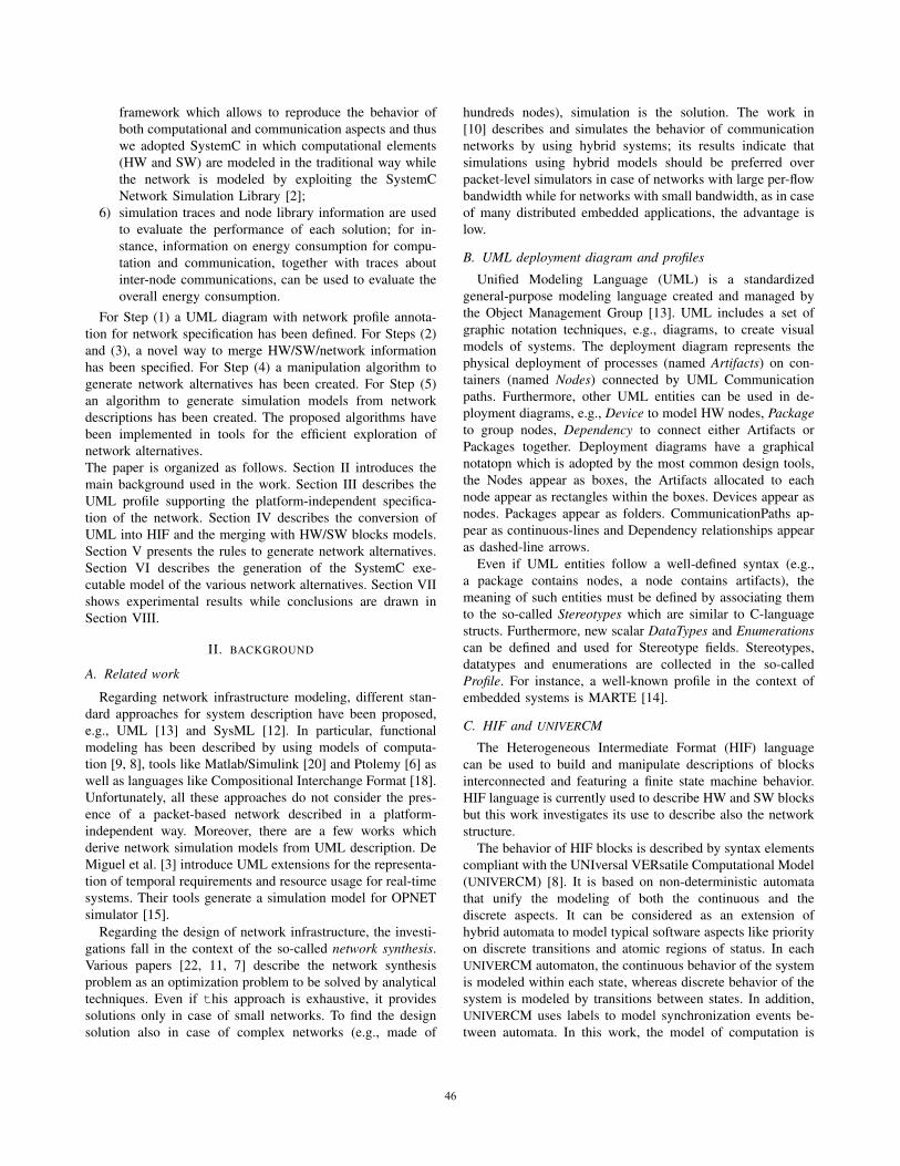
Figure 2 shows the use of the UML deployment diagram
and of the Network profile to model a simple monitoring
application which contains two sensor nodes (Node 0 and
Node 2), the channels, and the collector node (Node 1).
Node 0 and Node 1 are placed in the same zone (e.g., the
same room) and are connected by a wired channel. Node 2
is placed in a different zone and it is connected to Node 1
by a wireless channel represented by the Device entity (since
many nodes can be connected by the same shared channel).
Node 0 and Node 2 host a sensor task while Node 1 hosts a
collector task. Sensor tasks are connected to the collector task
by data flows.
Fig. 2. Deployment diagram of a network application.
IV. CONVERSION TO HIF/UNIVERCM
HIF provides entities to model both the structure and the
behavior of a system. The structural description of the network
is provided by the UML deployment diagram (Section III).
While, the behavior of the network is given by providing the
behavior of all tasks which are contained in network structure.
For standard traffic sources and sink, the behavior is assumed
to be known, while the behavior of user-defined tasks can be
specified by using UNIVERCM automata supported by HIF
syntax.
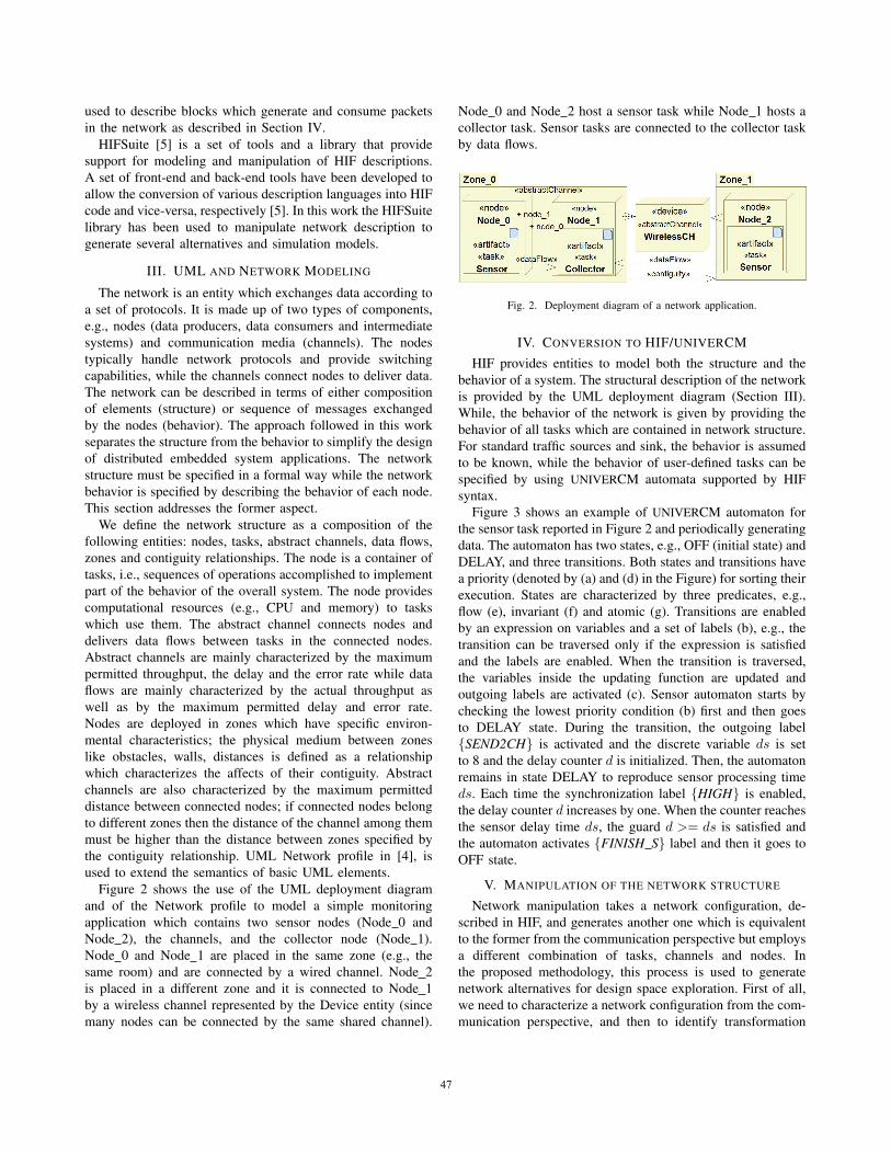
Figure 3 shows an example of UNIVERCM automaton for
the sensor task reported in Figure 2 and periodically generating
data. The automaton has two states, e.g., OFF (initial state) and
DELAY, and three transitions. Both states and transitions have
a priority (denoted by (a) and (d) in the Figure) for sorting their
execution. States are characterized by three predicates, e.g.,
flow (e), invariant (f) and atomic (g). Transitions are enabled
by an expression on variables and a set of labels (b), e.g., the
transition can be traversed only if the expression is satisfied
and the labels are enabled. When the transition is traversed,
the variables inside the updating function are updated and
outgoing labels are activated (c). Sensor automaton starts by
checking the lowest priority condition (b) first and then goes
to DELAY state. During the transition, the outgoing label
{SEND2CH} is activated and the discrete variable ds is set
to 8 and the delay counter d is initialized. Then, the automaton
remains in state DELAY to reproduce sensor processing time
ds. Each time the synchronization label {HIGH} is enabled,
the delay counter d increases by one. When the counter reaches
the sensor delay time ds, the guard d >= ds is satisfied and
the automaton activates {FINISH S} label and then it goes to
OFF state.
V. MANIPULATION OF THE NETWORK STRUCTURE
Network manipulation takes a network configuration, de-
scribed in HIF, and generates another one which is equivalent
to the former from the communication perspective but employs
a different combination of tasks, channels and nodes. In
the proposed methodology, this process is used to generate
network alternatives for design space exploration. First of all,
we need to characterize a network configuration from the com-
munication perspective, and then to identify transformation
47
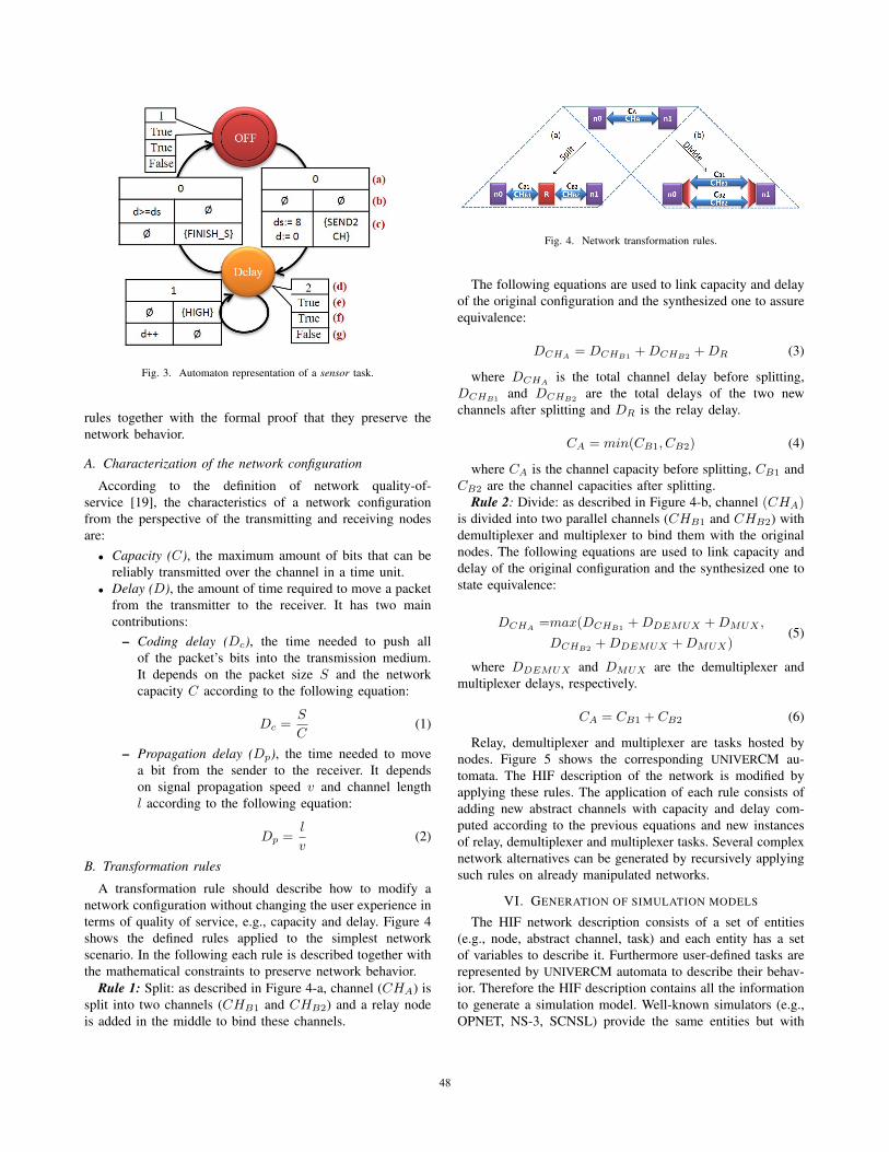
Fig. 3. Automaton representation of a sensor task.
rules together with the formal proof that they preserve the
network behavior.
A. Characterization of the network configuration
According to the definition of network quality-of-
service [19], the characteristics of a network configuration
from the perspective of the transmitting and receiving nodes
are:
• Capacity (C), the maximum amount of bits that can be
reliably transmitted over the channel in a time unit.
• Delay (D), the amount of time required to move a packet
from the transmitter to the receiver. It has two main
contributions:
– Coding delay (Dc), the time needed to push all
of the packet’s bits into the transmission medium.
It depends on the packet size S and the network
capacity C according to the following equation:
Dc =S
C(1)
– Propagation delay (Dp), the time needed to move
a bit from the sender to the receiver. It depends
on signal propagation speed v and channel length
l according to the following equation:
Dp =l
v(2)
B. Transformation rules
A transformation rule should describe how to modify a
network configuration without changing the user experience in
terms of quality of service, e.g., capacity and delay. Figure 4
shows the defined rules applied to the simplest network
scenario. In the following each rule is described together with
the mathematical constraints to preserve network behavior.
Rule 1: Split: as described in Figure 4-a, channel (CHA) is
split into two channels (CHB1 and CHB2) and a relay node
is added in the middle to bind these channels.
Fig. 4. Network transformation rules.
The following equations are used to link capacity and delay
of the original configuration and the synthesized one to assure
equivalence:
DCHA= DCHB1
+DCHB2+DR (3)
where DCHAis the total channel delay before splitting,
DCHB1and DCHB2
are the total delays of the two new
channels after splitting and DR is the relay delay.
CA = min(CB1, CB2) (4)
where CA is the channel capacity before splitting, CB1 and
CB2 are the channel capacities after splitting.
Rule 2: Divide: as described in Figure 4-b, channel (CHA)is divided into two parallel channels (CHB1 and CHB2) with
demultiplexer and multiplexer to bind them with the original
nodes. The following equations are used to link capacity and
delay of the original configuration and the synthesized one to
state equivalence:
DCHA=max(DCHB1
+DDEMUX +DMUX ,
DCHB2+DDEMUX +DMUX)
(5)
where DDEMUX and DMUX are the demultiplexer and
multiplexer delays, respectively.
CA = CB1 + CB2 (6)
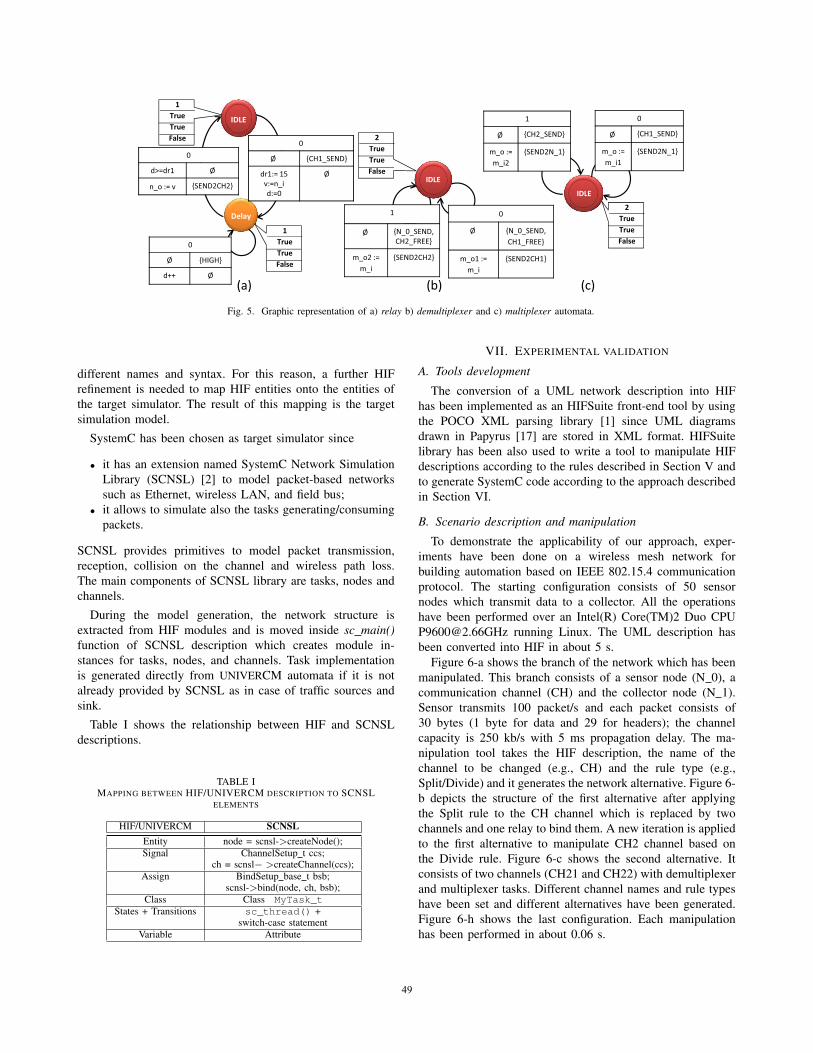
Relay, demultiplexer and multiplexer are tasks hosted by
nodes. Figure 5 shows the corresponding UNIVERCM au-
tomata. The HIF description of the network is modified by
applying these rules. The application of each rule consists of
adding new abstract channels with capacity and delay com-
puted according to the previous equations and new instances
of relay, demultiplexer and multiplexer tasks. Several complex
network alternatives can be generated by recursively applying
such rules on already manipulated networks.
VI. GENERATION OF SIMULATION MODELS
The HIF network description consists of a set of entities
(e.g., node, abstract channel, task) and each entity has a set
of variables to describe it. Furthermore user-defined tasks are
represented by UNIVERCM automata to describe their behav-
ior. Therefore the HIF description contains all the information
to generate a simulation model. Well-known simulators (e.g.,
OPNET, NS-3, SCNSL) provide the same entities but with
48
��,�
�����
�
������ �
� �� � ����������
�
� ������
��� �
!
��
��
��� �
!
��
��
��� �
�
� ���������
����� ��
����
����
���,�
�
� ��������
��������
�� ��
�
����������
�
� ��������
��������
�� ��
�
����������
"
��
��
��� �
��,�
�
� ���������
� ��
��
���������
�
� ���������
� ��
��
���������
"
��
��
��� �
!"# !$# !%#
Fig. 5. Graphic representation of a) relay b) demultiplexer and c) multiplexer automata.
different names and syntax. For this reason, a further HIF
refinement is needed to map HIF entities onto the entities of
the target simulator. The result of this mapping is the target
simulation model.
SystemC has been chosen as target simulator since
• it has an extension named SystemC Network Simulation
Library (SCNSL) [2] to model packet-based networks
such as Ethernet, wireless LAN, and field bus;
• it allows to simulate also the tasks generating/consuming
packets.
SCNSL provides primitives to model packet transmission,
reception, collision on the channel and wireless path loss.
The main components of SCNSL library are tasks, nodes and
channels.
During the model generation, the network structure is
extracted from HIF modules and is moved inside sc main()function of SCNSL description which creates module in-
stances for tasks, nodes, and channels. Task implementation
is generated directly from UNIVERCM automata if it is not
already provided by SCNSL as in case of traffic sources and
sink.
Table I shows the relationship between HIF and SCNSL
descriptions.
TABLE IMAPPING BETWEEN HIF/UNIVERCM DESCRIPTION TO SCNSL
ELEMENTS
HIF/UNIVERCM SCNSLEntity node = scnsl->createNode();Signal ChannelSetup t ccs;
ch = scnsl− >createChannel(ccs);Assign BindSetup base t bsb;
scnsl->bind(node, ch, bsb);Class Class MyTask_t
States + Transitions sc_thread() +switch-case statement
Variable Attribute
VII. EXPERIMENTAL VALIDATION
A. Tools development
The conversion of a UML network description into HIF
has been implemented as an HIFSuite front-end tool by using
the POCO XML parsing library [1] since UML diagrams
drawn in Papyrus [17] are stored in XML format. HIFSuite
library has been also used to write a tool to manipulate HIF
descriptions according to the rules described in Section V and
to generate SystemC code according to the approach described
in Section VI.
B. Scenario description and manipulation
To demonstrate the applicability of our approach, exper-
iments have been done on a wireless mesh network for
building automation based on IEEE 802.15.4 communication
protocol. The starting configuration consists of 50 sensor
nodes which transmit data to a collector. All the operations
have been performed over an Intel(R) Core(TM)2 Duo CPU
[email protected] running Linux. The UML description has
been converted into HIF in about 5 s.
Figure 6-a shows the branch of the network which has been
manipulated. This branch consists of a sensor node (N 0), a
communication channel (CH) and the collector node (N 1).
Sensor transmits 100 packet/s and each packet consists of
30 bytes (1 byte for data and 29 for headers); the channel
capacity is 250 kb/s with 5 ms propagation delay. The ma-
nipulation tool takes the HIF description, the name of the
channel to be changed (e.g., CH) and the rule type (e.g.,
Split/Divide) and it generates the network alternative. Figure 6-
b depicts the structure of the first alternative after applying
the Split rule to the CH channel which is replaced by two
channels and one relay to bind them. A new iteration is applied
to the first alternative to manipulate CH2 channel based on
the Divide rule. Figure 6-c shows the second alternative. It
consists of two channels (CH21 and CH22) with demultiplexer
and multiplexer tasks. Different channel names and rule types
have been set and different alternatives have been generated.
Figure 6-h shows the last configuration. Each manipulation
has been performed in about 0.06 s.
49

��� �
��� ���
��� �
��� ���
���� ��
��� �
��� ���
����
�����
��
��� �
��� ���
�
���
����
���
��
!�#
!�#
! #
!�#
��
�
�����
����
�
����
���
�
���
��
� � � � �
���
��� ���
Fig. 6. Block diagram of the different network alternatives.
C. Simulation and mapping over the actual platform
Each alternative (i.e., different HIF descriptions) is refined
to match the syntax of the target network simulator which is
SCNSL. After this refinement step, the standard HIF back-
end tool for SystemC is applied to generate SCNSL code
for simulation. Each model generation has been performed
in about 7 s. Figure 7 reports the number of SystemC lines
of code (LoC) for the eight cases (i.e., original configuration
and seven alternatives). The source length increases with
the number of manipulations showing that such exploration
becomes a very long and error-prone process if done manually.
Simulation length has been set to 10 s and statistics have
been collected to analyze network behavior.
By mapping simulated nodes onto an actual HW platform,
other performance metrics can be obtained as a function of the
network alternative; for instance, we evaluated system cost and
energy consumption. To obtain system cost we assumed that
all the nodes have the same cost and we simply reported the
number of nodes in Figure 7. To evaluate energy consumption
we analized energy spent for transmission. For each network
alternative the minimum transmission power has been set for
each link according to the inter-node distance. Then the energy
consumption has been evaluated by matching the transmission
power with current levels in the node data-sheet. Total and
sensor transmission energy is reported in Figure 7 as a function
of network alternatives. When the number of intermediate
nodes increases the total transmission energy increases but the
transmission energy of the sensor decreases since its signal has
to cover a shorter distance.
VIII. CONCLUSIONS
A methodology for the exploration of communication al-
ternatives in model-driven design of networked embedded
systems has been presented. An approach to merge such
structural details with the behavioral description of packet
generation/consumption has been shown. This description is
Fig. 7. Results of the exploration of design alternatives.
an efficient way to provide a path towards simulation. Fur-
thermore, manipulation rules have been defined to generate a
set of alternatives to be simulated and evaluated to find the
optimal design solution. All the steps have been supported
by the development of tools. The application of the flow to
a building automation example made of fifty nodes shows
that the generation of alternatives and of simulation models
allows fast design space exploration with respect to hand-
written code.
REFERENCES
[1] Applied Informatics Software Engineering GmbH.
POCO C++ Libraries. URL: http://pocoproject.org.
[2] SystemC Network Simulation Library – version 2, 2012.
URL: http://sourceforge.net/projects/scnsl.
[3] M. de Miguel, T. Lambolais, M. Hannouz, S. Betge-
Brezetz, and S. Piekarec. UML Extensions for the
Specification and Evaluation of Latency Constraints in
Architectural Models. In Proceedings of the 2nd inter-national workshop on Software and performance, WOSP
’00, pages 83–88, New York, NY, USA, 2000. ACM.
[4] E. Ebeid, F. Fummi, and D. Quaglia. A Toolchain for
UML-based Modeling and Simulation of Networked Em-
bedded Systems. In Proceedings of the 2013 UKSim 15thInternational Conference on Computer Modelling andSimulation, UKSIM ’13, pages 374–379, Washington,
DC, USA, 2013. IEEE Computer Society.
[5] EDALAB. HIFSuite: Tools and APIs for HDL Code
Conversion and Manipulation– version 2012.10, 2012.
http://www.hifsuite.com/.
[6] J. Eker, J. W. Janneck, E. A. Lee, J. Liu, X. Liu,
J. Ludvig, S. Neuendorffer, S. Sachs, and Y. Xiong.
Taming Heterogeneity - The Ptolemy Approach. Proc.of the IEEE, 91(1):127–144, 2003.
[7] F. Fummi, D. Quaglia, and F. Stefanni. Modeling of
50
Communication Infrastructure for Design-Space Explo-
ration. In Proc. of ECSI Forum on specification & DesignLanguages (FDL), 2010.
[8] L. D. Guglielmo, F. Fummi, G. Pravadelli, F. Stefanni,
and S. Vinco. UNIVERCM: the UNIversal VERsatile
Computational Model for Heterogeneous System Inte-
gration. IEEE Transactions on Computers, 99(PrePrints),
2012.
[9] F. Herrera and E. Villar. A Framework for Heterogeneous
Specication and Design of Electronic Embedded Systems
in SystemC. ACM Transactions on Design Automationof Electronic Systems, 12(3):1–31, August 2007.
[10] J. Lee, S. Bohacek, J. Hespanha, and K. Obraczka. Mod-
eling Communication Networks With Hybrid Systems.
Networking, IEEE/ACM Transactions on, 15(3):630 –
643, June 2007.
[11] F. Leonardi, A. Pinto, and L. P. Carloni. Synthesis of
Distributed Execution Platforms for Cyber-Physical Sys-
tems with Applications to High-Performance Buildings.
In ICCPS, pages 215–224. IEEE, 2011.
[12] Object Management Group. Sysml. URL:
http://www.sysml.org.
[13] Object Management Group. UML: Unified Modeling
Language. URL: http://www.uml.org.
[14] Object Management Group. A UML Profile for MARTE
(version 1.1). In OMG document number: formal/2011-06-02, June 2011. URL: http://www.omgmarte.org.
[15] OPNET Technologies, Inc. OPNET Manuals. URL:
http://www.opnet.com.
[16] D. Raychaudhuri and N. Mandayam. Frontiers of wire-
less and mobile communications. Proceedings of theIEEE, 100(4):824–840, April 2012.
[17] Sebastien Gerard et al. Papyrus UML. URL:
http://www.papyrusuml.org.
[18] C. Sonntag, R. Schiffelers, D. Van Beek, J. Rooda,
and S. Engell. Modeling and Simulation using the
Compositional Interchange Format for Hybrid Systems.
In Proc. of MATHMOD, pages 640–650, 2009.
[19] A. S. Tanenbaum. Computer Networks. Prentice Hall,
2003.
[20] The MathWorks. MATLAB and Simulink for Technical
Computing. URL: www.mathworks.com/.
[21] H. Viswanathan, B. Chen, and D. Pompili. Research
challenges in computation, communication, and context
awareness for ubiquitous healthcare. CommunicationsMagazine, IEEE, 50(5):92–99, May 2012.
[22] S. Xu, R. Kumar, and A. Pinto. Correct-by-Construction
and Optimal Synthesis of Beacon-Enabled ZigBee Net-
work. Automation Science and Engineering, IEEE Trans-actions on, PP(99):1, 2012.
51
Related Documents