Commonwealth of Kentucky Division for Air Quality STATEMENT OF BASIS / SUMMARY Title V/Title I, Construction/Operating Permit: V-20-015 Nucor Steel Gallatin, LLC 4831 US Highway 42 West Ghent, KY 41045-9704 January 8, 2021 Babak Fakharpour, Reviewer SOURCE ID: 21-077-00018 AGENCY INTEREST: 1449 ACTIVITY: APE20190016; APE20200009 Table of Contents SECTION 1 – SOURCE DESCRIPTION .............................................................................................. 2 SECTION 2 – CURRENT APPLICATION AND EMISSION SUMMARY FORM...................................... 5 SECTION 3 – EMISSIONS, LIMITATIONS AND BASIS ..................................................................... 69 SECTION 4 – SOURCE INFORMATION AND REQUIREMENTS ...................................................... 125 SECTION 5 – PERMITTING HISTORY .......................................................................................... 132 SECTION 6 – PERMIT APPLICATION HISTORY........................................................................... 133 APPENDIX A – ABBREVIATIONS AND ACRONYMS ..................................................................... 133

Welcome message from author
This document is posted to help you gain knowledge. Please leave a comment to let me know what you think about it! Share it to your friends and learn new things together.
Transcript
Commonwealth of Kentucky
Division for Air Quality
STATEMENT OF BASIS / SUMMARY
Title V/Title I, Construction/Operating
Permit: V-20-015
Nucor Steel Gallatin, LLC
4831 US Highway 42 West
Ghent, KY 41045-9704
January 8, 2021
Babak Fakharpour, Reviewer
SOURCE ID: 21-077-00018
AGENCY INTEREST: 1449
ACTIVITY: APE20190016; APE20200009
Table of Contents SECTION 1 – SOURCE DESCRIPTION .............................................................................................. 2
SECTION 2 – CURRENT APPLICATION AND EMISSION SUMMARY FORM ...................................... 5
SECTION 3 – EMISSIONS, LIMITATIONS AND BASIS ..................................................................... 69
SECTION 4 – SOURCE INFORMATION AND REQUIREMENTS ...................................................... 125
SECTION 5 – PERMITTING HISTORY .......................................................................................... 132
SECTION 6 – PERMIT APPLICATION HISTORY ........................................................................... 133
APPENDIX A – ABBREVIATIONS AND ACRONYMS ..................................................................... 133
Statement of Basis/Summary Page 2 of 133
Permit: V-20-015
SECTION 1 – SOURCE DESCRIPTION
SIC Code and description: 3316, Cold-Rolled Steel Sheet, Strip, and Bars
Single Source Det. ☒ Yes ☐ No If Yes, Affiliated Source AI: 1460
Source-wide Limit ☐ Yes ☒ No If Yes, See Section 4, Table A
28 Source Category ☒ Yes ☐ No If Yes, Category: Iron and steel mills
County: Gallatin
Nonattainment Area ☒ N/A ☐ PM10 ☐ PM2.5 ☐ CO ☐ NOX ☐ SO2 ☐ Ozone ☐ Lead
PTE* greater than 100 tpy for any criteria air pollutant ☒ Yes ☐ No
If yes, for what pollutant(s)?
☒ PM10 ☒ PM2.5 ☒ CO ☒ NOX ☒ SO2 ☒ VOC
PTE* greater than 250 tpy for any criteria air pollutant ☒ Yes ☐ No
If yes, for what pollutant(s)?
☒ PM10 ☒ PM2.5 ☒ CO ☒ NOX ☒ SO2 ☐ VOC
PTE* greater than 10 tpy for any single hazardous air pollutant (HAP) ☐ Yes ☒ No
PTE* greater than 25 tpy for combined HAP ☒ Yes ☐ No
*PTE does not include self-imposed emission limitations.
Description of Facility:
Nucor Steel Gallatin (NSG) is a steel recycling mini-mill located in Ghent, KY, along the Ohio
River, and northeast of Louisville, KY. The NSG mill recycles scrap steel and scrap substitutes
using the electric arc furnace (EAF) process. Scrap steel and scrap substitutes are brought to the
facility by barge, rail, and truck. Scrap steel, scrap substitutes, and flux are charged to the EAF
and melted by applying electric current through the feed mixture. Molten metal is tapped to a ladle
and is transferred to LMF, where the chemistry of the steel is adjusted. From the LMF, the molten
metal is transferred to a continuous caster, which cast steel slabs. To produce steel coils, the steel
slabs proceed through a tunnel furnace to the rolling mill, where it is rolled and shaped to its final
form. The hot rolled steel coils may be further processed through the pickle galvanizing line (PGL)
to produce pickled and oiled or galvanized coils.
The permit contains 3 alternate operating scenarios providing for continued operation of existing
units until the units that will replace them are built. They are as follows:
Emission Point 02-01 Slab Reheat Tunnel Furnace (124 MMBtu/hr) may be operated until
EP 02-01, A-Line Tunnel Furnace modification is completed (104.3 MMBtu/hr), and EP
02-04, 2-Stand Roughing Mill is constructed and operating.
Emission Point 01 (EP 03-01) Cooling Tower #1 (Laminar), Emission Point 06 (EP 03-06)
Support Cooling Tower, may be operated until EP 03-09 Laminar Cooling Tower Cells,
Statement of Basis/Summary Page 3 of 133
Permit: V-20-015
EP 03-10 Direct Cooling Tower Cells for Hot Mill, and EP 03-12 Cold Mill Cooling Tower
is constructed and operating.
The batch concrete plant will be used during construction activities and will be removed
from the Nucor property once foundation activities are complete. As such, EU 21, the Cold
Mill Complex (phase 2) and Batch Concrete Plant will not operate simultaneously.
The existing facility is classified as a single source with the adjacent Steel Technologies (Steel
Tech), LLC (Source ID 21-077-00018) facility for the purposes of 401 KAR 51:017, Prevention
of significant deterioration of air quality (PSD) and 401 KAR 52:020, Title V permits. As such,
emissions for the contiguous facilities are considered together and each holds its own Title V
permit, even if the emissions from the smaller facility would not, by themselves, cause the smaller
facility to be considered a major source. NSG also owns 50% of Steel Tech.
For the permit and statement of basis, equipment is gathered into Emission Units (EUs) based on
common function and area of the facility, such as Melt Shop #1 – 0E1 (EU 01), Melt Shop #2 (EU
20), Hot Rolling Mill (EU 02), etc. Individual equipment within each unit receives an Emission
Point (EP) number that identifies the unit first and then identifies the specific piece of equipment.
For example, the Single Shell DC Electric EAF in Melt Shop #2 is EP 20-01, i.e., this specific
emission point is from unit 20 (Melt Shop #2) and designated as the first point identified within
the unit.
Under this system, the Emission Units (EUs) are as follows:
EU 01 – Melt Shop #1 – 0E1
EU 02 – Hot Rolling Mill
EU 03 – Cooling Towers – 0T1
EU 04 – Existing Roads – 0RP
EU 05 – Barge Terminal – 0BL
EU 06 – LMF Alloy Handling & Storage – 0P1
EU 07 – Cleaning Tanks – 0D1
EU 08 – Emergency Generators > 500 HP – 0EG1
EU 09 – Emergency Generators < 500 HP
EU 10 – Miscellaneous Dust Sources – 0B1 & 0S1
EU 11 – Flux (Lime) Handling System
EU 12 – Carbon Handling System (formerly Recycling & Coal Drying) – 0RC
EU 13 – Direct Reduced Iron (DRI) Handling System
EU 15 – Pickle Galv Line (PGL)
EU 16 – PGL Finishing Operations
EU 19 – Slag Processing
EU 20 – Melt Shop #2
EU 21 – Cold Mill Complex
EU 23 – Air Separation Plant
EU 24 – Batch Concrete Plant
The permit and statement of basis also gathers emission points into Groups based on common
applicable requirements and compliance demonstrations. Refer to the permit and the tables in
Section 3 below for additional information regarding the groups, units, specific
equipment/emission points contained within each group and unit, applicable regulations, and

Statement of Basis/Summary Page 4 of 133
Permit: V-20-015
specific limitations and requirements. Maximum short term capacities are based on a 30-day
rolling average unless specified otherwise.
Statement of Basis/Summary Page 5 of 133
Permit: V-20-015
SECTION 2 – CURRENT APPLICATION AND EMISSION SUMMARY FORM
Permit Number: V-20-015 Activities: APE20190016; APE20200009
Received: 9/24/2019;10/15/2020 Application Complete Date(s): 1/8/2020;12/15/2020
Permit Action: ☐ Initial ☒ Renewal ☒ Significant Rev ☒ Minor Rev ☐ Administrative
Construction/Modification Requested? ☒Yes ☐No NSR Applicable? ☒Yes ☐No
Previous 502(b)(10) or Off-Permit Changes incorporated with this permit action ☒Yes ☐No
APE20190006 – Off-Permit Change: Batch concrete plant (EU24) location changed to
accommodate construction activities associated with the expansion project authorized with
Title V permit V-14-013 R5.
APE20190007 – Off-Permit Change: Location of the plasma cutter changed from the Rolling
Mill Building to a new building located adjacent to the Rolling Mill Building.
APE20190008 – Off-Permit Change: The maximum heat capacities of the Pickling Boilers #1
and #2 (EP 15-03 & EP 15-04) was corrected from 23 MMBtu/hr to 25.2 MMBtu/hr.
APE20190009 – Off-Permit Change: The maximum heat capacity of the Chromate roll coater
dryer (EP 16-04) was corrected from 8 MMBtu/hr to 9 MMBtu/hr and corrected a naming error
by changing “spent pickle liquor” to “ferrous chloride solution”.
APE20200003 – 502(b)(10) Change: Request for an alternate flow monitoring location for
Baghouse #3 for the Melt Shop #2 pursuant to 40 CFR 60.274a(e). The Division approves of
this request because it is for monitoring flow for only one control device, and the Division
expects that it will provide a continuous record of operation of the Melt Shop #2 capture
system.
Description of Action: In this renewal permit, the following changes were made:
APE20190014 – On September 10, 2019, NSG submitted a Minor Revision application
requesting the use of a dedicated baghouse in lieu of using Phoenix’s mobile baghouse to
control emissions from the coil cutting operations. The coil cutting operation and slag cutting
operation shared Phoenix’s mobile baghouse and was identified in the permit V-14-013 R5 as
EP 19-04. In this renewal, a new emission point identifies coil cutting operation (EP 02-08)
and this process is no longer combined with slag cutting operation. There is no emission change
due to this request. This application was deemed complete on September 16, 2019.
APE20190016 – On September 24, 2019, NSG submitted the Renewal application updating
the Compliance Assurance Monitoring (CAM) plan and Pollution Prevention Plan (PPP) for
the affected units. On December 29, 2020, Nucor submitted a letter requesting approval of a
combined flow monitoring location for Baghouses #1 & #2 for Melt Shop #1 (an identical
request as was made for Baghouse #3). This request is denied by the Division at this time due
to the inability of the Division to determine that one flow monitoring location for two control
devices and capture systems will accurately and adequately provide a continuous record of
operation of each emission capture system. Any request for determination related to this in the
future must include a robust data demonstration including simultaneous inlet and outlet
monitoring to demonstrate how compliance could be demonstrated. On January 6, 2021, NSG
Statement of Basis/Summary Page 6 of 133
Permit: V-20-015
submitted a request to remove EPs 12-04, 12-05, and 12-06 from the permit. These EPs were
removed from the site in May 2017.
APE20200001 – On January 27, 2020, NSG submitted a Minor Revision application
requesting incorporation of a U.S. EPA approved alternate monitoring procedure for the Pickle
Line Scrubber into the permit. This application was deemed complete on February 11, 2020.
APE20200002 – On March 10, 2020, NSG submitted a Minor Revision application requesting
removal of two emergency generators from a PSD revision application submitted on
September 13, 2019 (later withdrawn). NSG requested that these replacements be processed
separately as a minor revision since the replacements are not related to the PSD melt shop
expansion. This application was deemed complete on March 12, 2020.
APE20200008 – On September 30, 2020, NSG submitted a Minor Revision application to
incorporate all off-permit changes and other minor modifications previously submitted
regarding the Pickle and Galvanizing Line. This application was deemed complete on
December 14, 2020.
APE20200009 – On October 15, 2020, NSG submitted a revised PSD Significant Revision
application to replace the previous significant revision (previously submitted September 13,
2019) related to revising the project. This application incorporates final design specifications
that are different from the last expansion project permitted in V-14-013 R5 and requires re-
evaluation of the project. NSG has also requested authorization to construct additional support
equipment, revised the size of new or modified units, and eliminated units that are no longer
needed.
NSG also sent additional information regarding this PSD project revision on May 19th,
November 5th and 24th, December 1st, 11th, and 15th of 2020. On October 29, 2020, NSG
provided Volume II of the PSD application which included the air dispersion modeling data
and associated discussion. The Division requested additional information regarding this
submittal on December 5, 2020, and Nucor provided the requested information on December
11, 2020. A preconstruction monitoring waiver for PM10 was granted on December 15, 2020.
The Division sent Volume I of the application to the U.S. EPA and Federal Agencies on
October 20, 2020, and the additional Volume II application submittal including air dispersion
modeling files was sent to the U.S. EPA and Federal Agencies on November 18, 2020.
This permit includes the following overall changes:
Removal of some alternative operating scenarios that were either no longer needed, or would
not be implemented as originally proposed.
Permit language, such as compliance demonstration methods, precluded regulations, etc, has
been updated or added to be consistent and clear.
EP 20-05 A, B, & C, the ladle preheaters, will be discharged to the Melt Shop #1 Baghouse 2
via the capture system. As such, the emissions from the ladle preheaters has been incorporated
into the existing emission limits for the combined Melt Shop #1 Baghouses Stack.
Accordingly, a separate emission limitation has not been set.
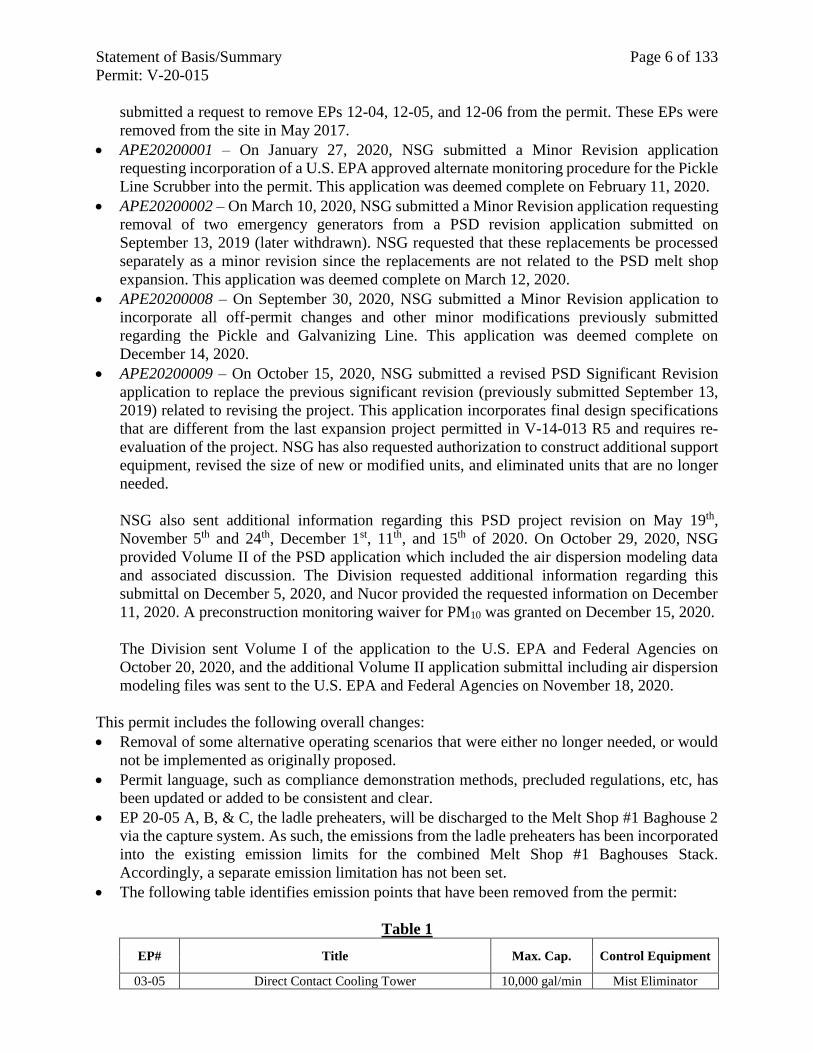
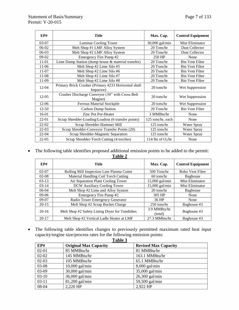
The following table identifies emission points that have been removed from the permit:
Table 1
EP# Title Max. Cap. Control Equipment
03-05 Direct Contact Cooling Tower 10,000 gal/min Mist Eliminator
Statement of Basis/Summary Page 7 of 133
Permit: V-20-015
EP# Title Max. Cap. Control Equipment
03-07 Laminar Cooling Tower 30,000 gal/min Mist Eliminator
06-02 Melt Shop #1 LMF Alloy System 20 Tons/hr Dust Collector
06-03 Melt Shop #2 LMF Alloy System 20 Tons/hr Dust Collector
09-02 Emergency Fire Pump #2 250 HP None
11-01 Lime Dump Station (dump house & material transfer) 20 Tons/hr Bin Vent Filter
11-06 Melt Shop #2 Lime Silo #5 20 Tons/hr Bin Vent Filter
11-07 Melt Shop #2 Lime Silo #6 20 Tons/hr Bin Vent Filter
11-08 Melt Shop #2 Lime Silo #7 20 Tons/hr Bin Vent Filter
11-09 Melt Shop #2 Lime Silo #8 20 Tons/hr Bin Vent Filter
12-04 Primary Brick Crusher (Primary 4233 Horizontal shaft
Impactor) 20 tons/hr Wet Suppression
12-05 Crusher Discharge Conveyor (30” with Cross-Belt
Magnet) 20 tons/hr Wet Suppression
12-06 Ferrous Material Stockpile 20 tons/hr Wet Suppression
12-50 Carbon Dump Station 20 Tons/hr Bin Vent Filter
16-01 Zinc Pot Pre-Heater 3 MMBtu/hr None
22-01 Scrap Shredder-Loading/Loadout (6 transfer points) 125 tons/hr, each None
22-02 Scrap Shredder-Hammer Mill 125 tons/hr Water Spray
22-03 Scrap Shredder-Conveyor Transfer Points (20) 125 tons/hr Water Spray
22-04 Scrap Shredder-Magnetic Separation 125 tons/hr Water Spray
22-05 Scrap Shredder-Torch Cutting (4 torches) 114 lbs of O2/hr None
The following table identifies proposed additional emission points to be added to the permit:
Table 2
EP# Title Max. Cap. Control Equipment
02-07 Rolling Mill Inspection Line Plasma Cutter 500 Tons/hr Robo Vent Filter
02-08 Material Handling Coil Torch Cutting 60 tons/hr Baghouse
03-13 Air Separation Plant Cooling Tower 15,000 gal/min Mist Eliminator
03-14 DCW Auxiliary Cooling Tower 15,000 gal/min Mist Eliminator
06-04 Melt Shop #2 Lime and Alloy System 20 tons/hr Baghouse
09-06 Emergency Fire Pump #2 305 HP None
09-07 Radio Tower Emergency Generator 36 HP None
20-15 Melt Shop #2 Scrap Bucket Charge 250 tons/hr Baghouse #3
20-16 Melt Shop #2 Safety Lining Dryer for Tundishes 3.9 MMBty/hr
(total) Baghouse #3
20-17 Melt Shop #2 Vertical Ladle Heater at LMF 27.3 MMbtu/hr Baghouse #3
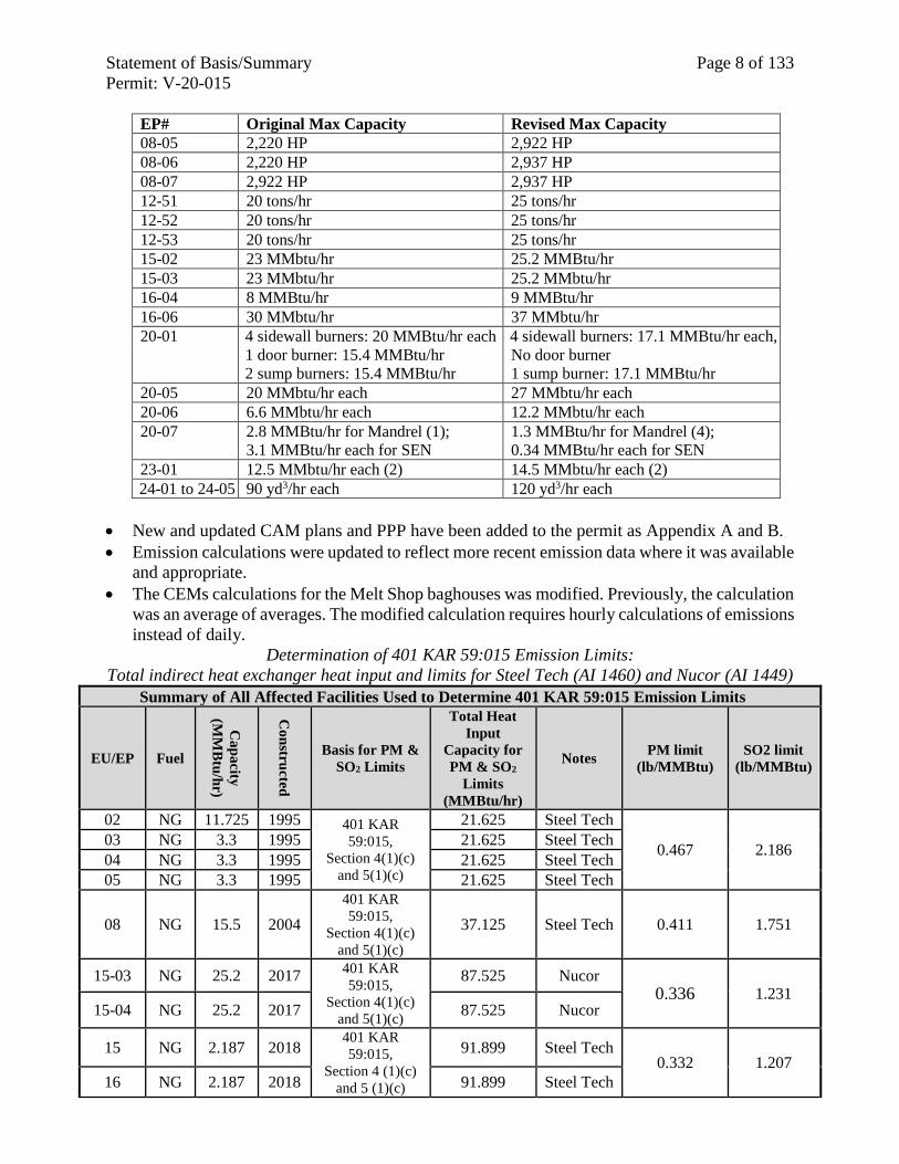
The following table identifies changes to previously permitted maximum rated heat input
capacity/engine size/process rates for the following emission points:
Table 3 EP# Original Max Capacity Revised Max Capacity
02-01 85 MMBtu/hr 81 MMBtu/hr
02-02 145 MMBtu/hr 163.1 MMBtu/hr
02-03 105 MMBtu/hr 65.1 MMBtu/hr
03-08 10,000 gal/min 8,000 gal/min
03-09 30,000 gal/min 35,000 gal/min
03-10 36,000 gal/min 26,300 gal/min
03-11 81,200 gal/min 59,500 gal/min
08-04 2,220 HP 2,922 HP
Statement of Basis/Summary Page 8 of 133
Permit: V-20-015
EP# Original Max Capacity Revised Max Capacity
08-05 2,220 HP 2,922 HP
08-06 2,220 HP 2,937 HP
08-07 2,922 HP 2,937 HP
12-51 20 tons/hr 25 tons/hr
12-52 20 tons/hr 25 tons/hr
12-53 20 tons/hr 25 tons/hr
15-02 23 MMbtu/hr 25.2 MMBtu/hr
15-03 23 MMbtu/hr 25.2 MMbtu/hr
16-04 8 MMBtu/hr 9 MMBtu/hr
16-06 30 MMbtu/hr 37 MMbtu/hr
20-01 4 sidewall burners: 20 MMBtu/hr each
1 door burner: 15.4 MMBtu/hr
2 sump burners: 15.4 MMBtu/hr
4 sidewall burners: 17.1 MMBtu/hr each,
No door burner
1 sump burner: 17.1 MMBtu/hr
20-05 20 MMbtu/hr each 27 MMbtu/hr each
20-06 6.6 MMbtu/hr each 12.2 MMbtu/hr each
20-07 2.8 MMBtu/hr for Mandrel (1);
3.1 MMBtu/hr each for SEN
1.3 MMBtu/hr for Mandrel (4);
0.34 MMBtu/hr each for SEN
23-01 12.5 MMbtu/hr each (2) 14.5 MMbtu/hr each (2)
24-01 to 24-05 90 yd3/hr each 120 yd3/hr each
New and updated CAM plans and PPP have been added to the permit as Appendix A and B.
Emission calculations were updated to reflect more recent emission data where it was available
and appropriate.
The CEMs calculations for the Melt Shop baghouses was modified. Previously, the calculation
was an average of averages. The modified calculation requires hourly calculations of emissions
instead of daily.
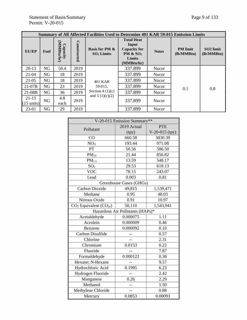
Determination of 401 KAR 59:015 Emission Limits:
Total indirect heat exchanger heat input and limits for Steel Tech (AI 1460) and Nucor (AI 1449)
Summary of All Affected Facilities Used to Determine 401 KAR 59:015 Emission Limits
EU/EP Fuel
Ca
pa
city
(MM
Btu
/hr)
Co
nstru
cted
Basis for PM &
SO2 Limits
Total Heat
Input
Capacity for
PM & SO2
Limits
(MMBtu/hr)
Notes PM limit
(lb/MMBtu)
SO2 limit
(lb/MMBtu)
02 NG 11.725 1995 401 KAR
59:015,
Section 4(1)(c)
and 5(1)(c)
21.625 Steel Tech
0.467 2.186 03 NG 3.3 1995 21.625 Steel Tech
04 NG 3.3 1995 21.625 Steel Tech 05 NG 3.3 1995 21.625 Steel Tech
08 NG 15.5 2004
401 KAR
59:015,
Section 4(1)(c)
and 5(1)(c)
37.125 Steel Tech 0.411 1.751
15-03 NG 25.2 2017 401 KAR
59:015,
Section 4(1)(c)
and 5(1)(c)
87.525 Nucor 0.336 1.231
15-04 NG 25.2 2017 87.525 Nucor
15 NG 2.187 2018 401 KAR
59:015,
Section 4 (1)(c)
and 5 (1)(c)
91.899 Steel Tech 0.332 1.207
16 NG 2.187 2018 91.899 Steel Tech
Statement of Basis/Summary Page 9 of 133
Permit: V-20-015
Summary of All Affected Facilities Used to Determine 401 KAR 59:015 Emission Limits
EU/EP Fuel
Ca
pa
city
(MM
Btu
/hr)
Co
nstru
cted
Basis for PM &
SO2 Limits
Total Heat
Input
Capacity for
PM & SO2
Limits
(MMBtu/hr)
Notes PM limit
(lb/MMBtu)
SO2 limit
(lb/MMBtu)
20-13 NG 50.4 2019
401 KAR
59:015,
Section 4 (1)(c)
and 5 (1)(c)(2)
337.899 Nucor
0.1 0.8
21-04 NG 18 2019 337.899 Nucor
21-05 NG 18 2019 337.899 Nucor
21-07B NG 23 2019 337.899 Nucor
21-08B NG 36 2019 337.899 Nucor
21-15
(15 units) NG
4.8
each 2019 337.899 Nucor
23-01 NG 29 2019 337.899 Nucor
V-20-015 Emission Summary**
Pollutant 2019 Actual
(tpy)
PTE
V-20-015 (tpy)
CO 660.58 3830.39
NOX 193.44 971.08
PT 50.56 586.50
PM10 21.44 856.82
PM2.5 13.59 548.17
SO2 29.53 618.13
VOC 78.15 243.07
Lead 0.003 0.81
Greenhouse Gases (GHGs)
Carbon Dioxide 49,815 1,539,471
Methane 0.95 48.03
Nitrous Oxide 0.91 10.97
CO2 Equivalent (CO2e) 50,110 1,543,941
Hazardous Air Pollutants (HAPs)*
Acetaldehyde 0.000075 1.11
Acrolein 0.000009 0.46
Benzene 0.000092 0.10
Carbon Disulfide -- 0.57
Chlorine -- 2.31
Chromium 0.0153 0.22
Fluoride -- 7.87
Formaldehyde 0.000122 0.38
Hexane; N-Hexane -- 9.57
Hydrochloric Acid 0.1995 6.23
Hydrogen Fluoride -- 2.42
Manganese 0.26 2.29
Methanol -- 1.50
Methylene Chloride -- 0.88
Mercury 0.0853 0.00093
Statement of Basis/Summary Page 10 of 133
Permit: V-20-015
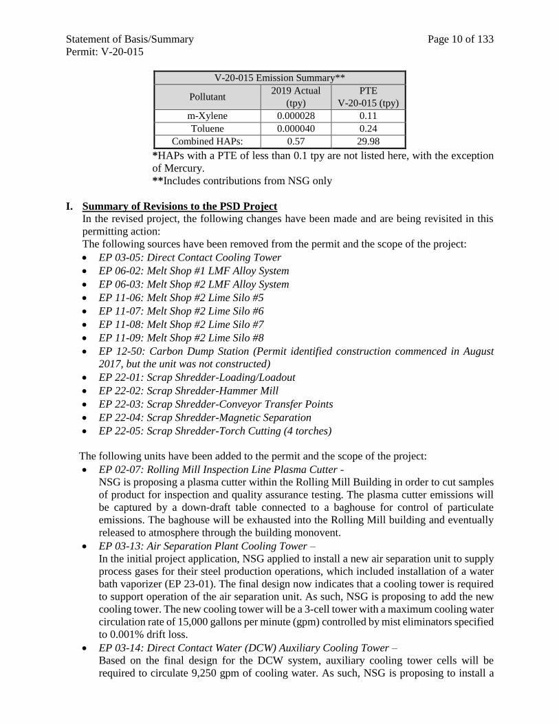
V-20-015 Emission Summary**
Pollutant 2019 Actual
(tpy)
PTE
V-20-015 (tpy)
m-Xylene 0.000028 0.11
Toluene 0.000040 0.24
Combined HAPs: 0.57 29.98
*HAPs with a PTE of less than 0.1 tpy are not listed here, with the exception
of Mercury.
**Includes contributions from NSG only
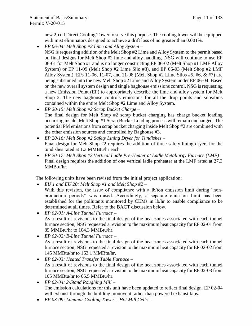
I. Summary of Revisions to the PSD Project
In the revised project, the following changes have been made and are being revisited in this
permitting action:
The following sources have been removed from the permit and the scope of the project:
EP 03-05: Direct Contact Cooling Tower
EP 06-02: Melt Shop #1 LMF Alloy System
EP 06-03: Melt Shop #2 LMF Alloy System
EP 11-06: Melt Shop #2 Lime Silo #5
EP 11-07: Melt Shop #2 Lime Silo #6
EP 11-08: Melt Shop #2 Lime Silo #7
EP 11-09: Melt Shop #2 Lime Silo #8
EP 12-50: Carbon Dump Station (Permit identified construction commenced in August
2017, but the unit was not constructed)
EP 22-01: Scrap Shredder-Loading/Loadout
EP 22-02: Scrap Shredder-Hammer Mill
EP 22-03: Scrap Shredder-Conveyor Transfer Points
EP 22-04: Scrap Shredder-Magnetic Separation
EP 22-05: Scrap Shredder-Torch Cutting (4 torches)
The following units have been added to the permit and the scope of the project:
EP 02-07: Rolling Mill Inspection Line Plasma Cutter -
NSG is proposing a plasma cutter within the Rolling Mill Building in order to cut samples
of product for inspection and quality assurance testing. The plasma cutter emissions will
be captured by a down-draft table connected to a baghouse for control of particulate
emissions. The baghouse will be exhausted into the Rolling Mill building and eventually
released to atmosphere through the building monovent.
EP 03-13: Air Separation Plant Cooling Tower –
In the initial project application, NSG applied to install a new air separation unit to supply
process gases for their steel production operations, which included installation of a water
bath vaporizer (EP 23-01). The final design now indicates that a cooling tower is required
to support operation of the air separation unit. As such, NSG is proposing to add the new
cooling tower. The new cooling tower will be a 3-cell tower with a maximum cooling water
circulation rate of 15,000 gallons per minute (gpm) controlled by mist eliminators specified
to 0.001% drift loss.
EP 03-14: Direct Contact Water (DCW) Auxiliary Cooling Tower –
Based on the final design for the DCW system, auxiliary cooling tower cells will be
required to circulate 9,250 gpm of cooling water. As such, NSG is proposing to install a
Statement of Basis/Summary Page 11 of 133
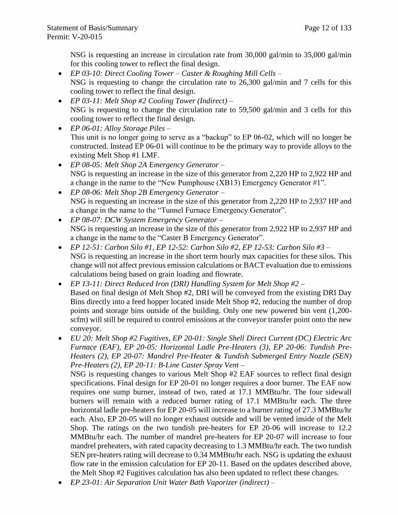
Permit: V-20-015
new 2-cell Direct Cooling Tower to serve this purpose. The cooling tower will be equipped
with mist eliminators designed to achieve a drift loss of no greater than 0.001%.
EP 06-04: Melt Shop #2 Lime and Alloy System –
NSG is requesting addition of the Melt Shop #2 Lime and Alloy System to the permit based
on final designs for Melt Shop #2 lime and alloy handling. NSG will continue to use EP
06-01 for Melt Shop #1 and is no longer constructing EP 06-02 (Melt Shop #1 LMF Alloy
System) or EP 11-09 (Melt Shop #2 Lime Silo #8), and EP 06-03 (Melt Shop #2 LMF
Alloy System), EPs 11-06, 11-07, and 11-08 (Melt Shop #2 Lime Silos #5, #6, & #7) are
being subsumed into the new Melt Shop #2 Lime and Alloy System under EP 06-04. Based
on the new overall system design and single baghouse emissions control, NSG is requesting
a new Emission Point (EP) to appropriately describe the lime and alloy system for Melt
Shop 2. The new baghouse controls emissions for all the drop points and silos/bins
contained within the entire Melt Shop #2 Lime and Alloy System.
EP 20-15: Melt Shop #2 Scrap Bucket Charge –
The final design for Melt Shop #2 scrap bucket charging has charge bucket loading
occurring inside; Melt Shop #1 Scrap Bucket Loading process will remain unchanged. The
potential PM emissions from scrap bucket charging inside Melt Shop #2 are combined with
the other emission sources and controlled by Baghouse #3.
EP 20-16: Melt Shop #2 Safety Lining Dryer for Tundishes –
Final design for Melt Shop #2 requires the addition of three safety lining dryers for the
tundishes rated at 1.3 MMBtu/hr each.
EP 20-17: Melt Shop #2 Vertical Ladle Pre-Heater at Ladle Metallurgy Furnace (LMF) –
Final design requires the addition of one vertical ladle preheater at the LMF rated at 27.3
MMBtu/hr.
The following units have been revised from the initial project application:
EU 1 and EU 20: Melt Shop #1 and Melt Shop #2 –
With this revision, the issue of compliance with a lb/ton emission limit during “non-
production periods” was raised. Accordingly, a separate emission limit has been
established for the pollutants monitored by CEMs in lb/hr to enable compliance to be
determined at all times. Refer to the BACT discussion below.
EP 02-01: A-Line Tunnel Furnace –
As a result of revisions to the final design of the heat zones associated with each tunnel
furnace section, NSG requested a revision to the maximum heat capacity for EP 02-01 from
85 MMBtu/hr to 104.3 MMBtu/hr.
EP 02-02: B-Line Tunnel Furnace –
As a result of revisions to the final design of the heat zones associated with each tunnel
furnace section, NSG requested a revision to the maximum heat capacity for EP 02-02 from
145 MMBtu/hr to 163.1 MMBtu/hr.
EP 02-03: Heated Transfer Table Furnace –
As a result of revisions to the final design of the heat zones associated with each tunnel
furnace section, NSG requested a revision to the maximum heat capacity for EP 02-03 from
105 MMBtu/hr to 65.5 MMBtu/hr.
EP 02-04: 2-Stand Roughing Mill –
The emission calculations for this unit have been updated to reflect final design. EP 02-04
will exhaust through the building monovent rather than powered exhaust fans.
EP 03-09: Laminar Cooling Tower – Hot Mill Cells –
Statement of Basis/Summary Page 12 of 133
Permit: V-20-015
NSG is requesting an increase in circulation rate from 30,000 gal/min to 35,000 gal/min
for this cooling tower to reflect the final design.
EP 03-10: Direct Cooling Tower – Caster & Roughing Mill Cells –
NSG is requesting to change the circulation rate to 26,300 gal/min and 7 cells for this
cooling tower to reflect the final design.
EP 03-11: Melt Shop #2 Cooling Tower (Indirect) –
NSG is requesting to change the circulation rate to 59,500 gal/min and 3 cells for this
cooling tower to reflect the final design.
EP 06-01: Alloy Storage Piles –
This unit is no longer going to serve as a “backup” to EP 06-02, which will no longer be
constructed. Instead EP 06-01 will continue to be the primary way to provide alloys to the
existing Melt Shop #1 LMF.
EP 08-05: Melt Shop 2A Emergency Generator –
NSG is requesting an increase in the size of this generator from 2,220 HP to 2,922 HP and
a change in the name to the “New Pumphouse (XB13) Emergency Generator #1”.
EP 08-06: Melt Shop 2B Emergency Generator –
NSG is requesting an increase in the size of this generator from 2,220 HP to 2,937 HP and
a change in the name to the “Tunnel Furnace Emergency Generator”.
EP 08-07: DCW System Emergency Generator –
NSG is requesting an increase in the size of this generator from 2,922 HP to 2,937 HP and
a change in the name to the “Caster B Emergency Generator”.
EP 12-51: Carbon Silo #1, EP 12-52: Carbon Silo #2, EP 12-53: Carbon Silo #3 –
NSG is requesting an increase in the short term hourly max capacities for these silos. This
change will not affect previous emission calculations or BACT evaluation due to emissions
calculations being based on grain loading and flowrate.
EP 13-11: Direct Reduced Iron (DRI) Handling System for Melt Shop #2 –
Based on final design of Melt Shop #2, DRI will be conveyed from the existing DRI Day
Bins directly into a feed hopper located inside Melt Shop #2, reducing the number of drop
points and storage bins outside of the building. Only one new powered bin vent (1,200-
scfm) will still be required to control emissions at the conveyor transfer point onto the new
conveyor.
EU 20: Melt Shop #2 Fugitives, EP 20-01: Single Shell Direct Current (DC) Electric Arc
Furnace (EAF), EP 20-05: Horizontal Ladle Pre-Heaters (3), EP 20-06: Tundish Pre-
Heaters (2), EP 20-07: Mandrel Pre-Heater & Tundish Submerged Entry Nozzle (SEN)
Pre-Heaters (2), EP 20-11: B-Line Caster Spray Vent –
NSG is requesting changes to various Melt Shop #2 EAF sources to reflect final design
specifications. Final design for EP 20-01 no longer requires a door burner. The EAF now
requires one sump burner, instead of two, rated at 17.1 MMBtu/hr. The four sidewall
burners will remain with a reduced burner rating of 17.1 MMBtu/hr each. The three
horizontal ladle pre-heaters for EP 20-05 will increase to a burner rating of 27.3 MMBtu/hr
each. Also, EP 20-05 will no longer exhaust outside and will be vented inside of the Melt
Shop. The ratings on the two tundish pre-heaters for EP 20-06 will increase to 12.2
MMBtu/hr each. The number of mandrel pre-heaters for EP 20-07 will increase to four
mandrel preheaters, with rated capacity decreasing to 1.3 MMBtu/hr each. The two tundish
SEN pre-heaters rating will decrease to 0.34 MMBtu/hr each. NSG is updating the exhaust
flow rate in the emission calculation for EP 20-11. Based on the updates described above,
the Melt Shop #2 Fugitives calculation has also been updated to reflect these changes.
EP 23-01: Air Separation Unit Water Bath Vaporizer (indirect) –
Statement of Basis/Summary Page 13 of 133
Permit: V-20-015
The water bath vaporizer is a backup unit employed when the air separation plant is down
or the nitrogen or oxygen demand is more than the air separation plant is generating. During
these events, liquefied gas maintained in storage tanks is passed through the Water Bath
Vaporizer to vaporize the liquefied gas prior to distributing the gas to the process
operations. Final design for the vaporizer will consist of two 14.5 MMBtu/hr natural gas-
fired, low NOx burners to heat the water bath (29 MMBtu/hr total) which can operate
simultaneously. The combustion gases from the indirect-fired burners will exhaust directly
to the atmosphere via individual stacks.
EU 24 – Batch Concrete Plant –
Based on construction needs, NSG is requesting an increase of the maximum daily concrete
production rate to 120 cubic yards per hour and 60,000 cubic yards per year.
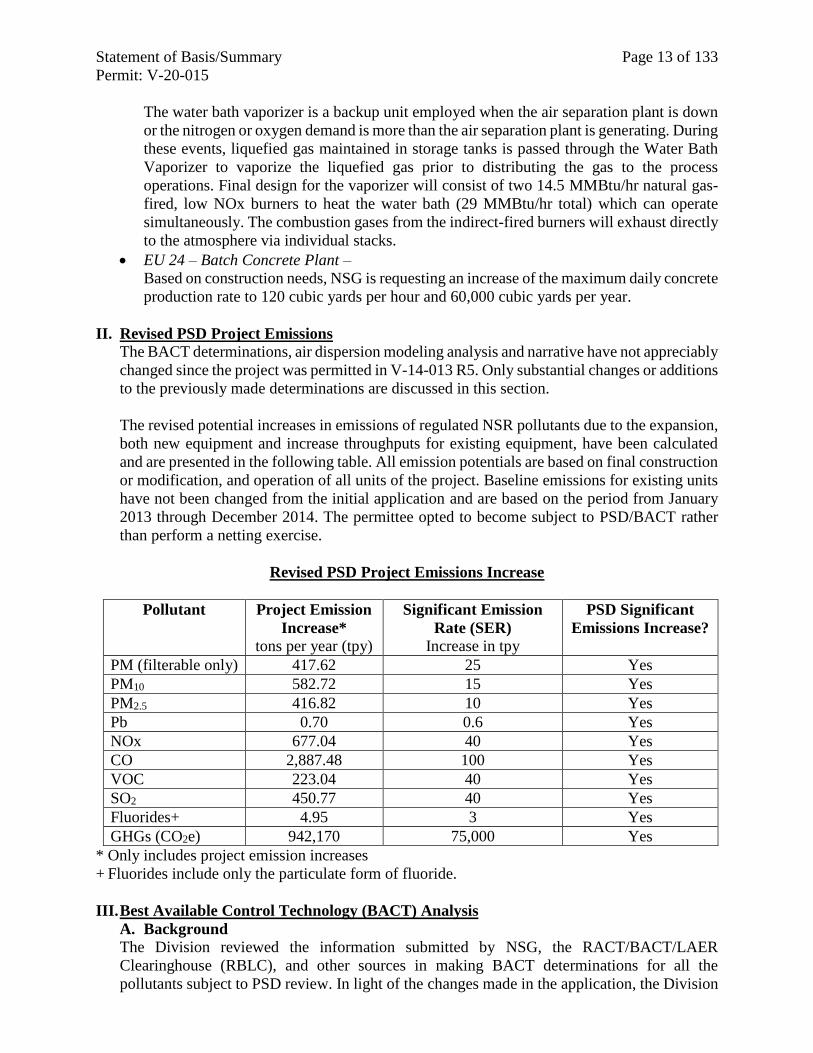
II. Revised PSD Project Emissions
The BACT determinations, air dispersion modeling analysis and narrative have not appreciably
changed since the project was permitted in V-14-013 R5. Only substantial changes or additions
to the previously made determinations are discussed in this section.
The revised potential increases in emissions of regulated NSR pollutants due to the expansion,
both new equipment and increase throughputs for existing equipment, have been calculated
and are presented in the following table. All emission potentials are based on final construction
or modification, and operation of all units of the project. Baseline emissions for existing units
have not been changed from the initial application and are based on the period from January
2013 through December 2014. The permittee opted to become subject to PSD/BACT rather
than perform a netting exercise.
Revised PSD Project Emissions Increase
Pollutant Project Emission
Increase*
tons per year (tpy)
Significant Emission
Rate (SER)
Increase in tpy
PSD Significant
Emissions Increase?
PM (filterable only) 417.62 25 Yes
PM10 582.72 15 Yes
PM2.5 416.82 10 Yes
Pb 0.70 0.6 Yes
NOx 677.04 40 Yes
CO 2,887.48 100 Yes
VOC 223.04 40 Yes
SO2 450.77 40 Yes
Fluorides+ 4.95 3 Yes
GHGs (CO2e) 942,170 75,000 Yes
* Only includes project emission increases
+ Fluorides include only the particulate form of fluoride.
III. Best Available Control Technology (BACT) Analysis
A. Background
The Division reviewed the information submitted by NSG, the RACT/BACT/LAER
Clearinghouse (RBLC), and other sources in making BACT determinations for all the
pollutants subject to PSD review. In light of the changes made in the application, the Division
Statement of Basis/Summary Page 14 of 133
Permit: V-20-015
reevaluated previously made BACT determinations for all pollutants as appropriate for each
unit. Any previously made BACT determinations that have not changed will not be repeated
here. NSG followed the same “top-down” process for the revised BACT as performed
previously.
A summary of the updated BACT analyses and Division decisions is outlined below.
B. BACT for PM, PM10, PM2.5, and Lead
1. General Control Measures for PM, PM10, PM2.5, and Lead
NSG submitted BACT analyses for PM, PM10, PM2.5, and Lead, but addressed all three
types of PM and Pb together since the same control technologies and practices reduce all
four of these emissions. For this project, all of the Pb emissions are assumed to be
particulate and are subject to the same emissions control technologies as those applicable
to particulate in general. Any reference to PM in this section refers only to filterable PM,
whereas PM10 and PM2.5 includes filterable and condensable components.
NSG also evaluated the particulate/lead control technologies in light of the groups of
equipment likely to be served by a single control device. As with the assignment of
BACT limits, discussed above, the technology chosen to control a particular final
emission point may serve as the BACT control for a diverse group of equipment.
Technologies for Particulate Control and Lead: The technologies identified as
possible BACT controls for the three types of particulate for the NSG project are the
following:
Cyclones: These mechanical collectors work on the principal of inertial separation. The
collectors use a rapid change in air direction and the property of inertia to separate mass
(particulate) from the process gas stream. This type of control is often used when there
is a high concentration of coarse particulate. A cyclone is a feasible control, but has a
lower collection efficiency (about 70 %), over the range of possible particulate sizes and
are most effective for particulate of >10 micron size. They are often used as pre-controls
to reduce particle concentration in a gas stream before it enters a second control device.
Scrubbers: In a wet scrubber, the process gas stream is either sprayed with a liquid or
forced into contact with a liquid in order to impact and remove particles entrained in the
gas. The particles are captured in liquid droplets that are then collected from the gas
stream in a mist eliminator. The resulting liquid is then treated to remove the particles
and recycled or discharged. Wet scrubbers are especially useful when the particulate is
sticky, combustive, corrosive or explosive. Dry scrubbers, which do not saturate the gas
stream, are generally used to remove acids from waste gas and are not used for particulate
control.
Electrostatic precipitators (ESPs): ESPs are another control technology often used to
remove particulate from flue gases before they are released to atmosphere. In this
technology, particulate entrained in a gas stream is given an electrical charge as the
stream passes through a gaseous ion region (corona). The charged particles are then
attracted to, and collected by, a neutral or oppositely charged collector plate. In a dry
electrostatic precipitator (ESPs), the collector plate is subjected to intermittent
Statement of Basis/Summary Page 15 of 133
Permit: V-20-015
mechanical or sonic percussion to knock the particles off the plate and into a hopper
positioned under the plate. A wet ESP operates similarly to the dry ESP for removing
PM from a gas stream, but the collecting surface is cleaned by water, either intermittently
or continuously.
Cartridge Collectors: These devices use a nonwoven filtering media, as opposed to
woven or felt bags used in baghouses (see below, Fabric Filters). The filter media (fabric)
is supported by an inner and outer wire framework and is pleated to increase filtering
surface area. As a gas stream passes through the filter, particle collects on the surface of
the filtering media. Cartridge collectors can be single use or continuous duty designs. In
single-use, the dirty cartridges are changed and collected dirt is removed while the
collector is off. In the continuous duty design, the cartridges are cleaned by pulse-jet
cleaning system where a high pressure blast of air is used to remove dust from the filter
media by flexing the media, discharging the dust cake gathered on the surface.
Fabric Filters (baghouses): This type of control equipment consists of a series of bags
(filters) contained in a shell structure, through which process gas or a dust laden air
stream is passed. Baghouses function based on the fact that particles are larger than gas
molecules. When a particulate-laden gas is passed through a membrane (fabric filter), the
particulate is captured on the filter while the clean gas passes through. The bags can be
of woven or felted cotton, synthetic, or glass-fiber material in either a tube or envelope
shape. Fabric filters, and the materials from which they are made, can be chosen to
effectively clean particulates based on the sizes, shapes, and textures of the particulate
expected. Baghouses also have cleaning devices, such as pulse jet, shakers or rappers,
reverse air capability, or sonic cleaners, that cause collected dust to fall into dust hoppers
at the bottom of the shell structure. The particulate removal efficiency of a baghouse can
be as high as 99.9 %. The bin vent filters used in the NSG project are in to this category
of control.
Enclosure: Placing operations within a building or enclosure protects surfaces from air
currents and prevents dust from becoming airborne. Depending on the openings, such as
vents, windows and doors, and fans used, buildings can provide up to 70% efficient
reduction in particulates generated within the structure. Building enclosures around
conveyors and material piles also provides protection against particles becoming
airborne.
Good Combustion and Operation Practices: This is a combustion optimization work
practices method for minimizing fuel use and emissions from the burning of fossil fuels.
Oxygen and carbon in the fuel combine during combustion in a complex process
requiring turbulence, temperature and time for the reactants to contact and combine to
form carbon dioxide (CO2) and heat. If the combustion and combination of necessary
elements are not controlled, the combustion of the fuel is incomplete and undesirable
emissions form. Although particulate from natural gas combustion is normally a small
amount, poor air/fuel mixing or maintenance problems can cause extra PM to form.
Particulates from natural gas combustion are usually larger molecular weight
hydrocarbons that are not fully combusted. Increased CO also occurs when there is poor
mixing (not enough turbulence) and/or there is not enough air in the mix. Other pollutants
such as NOx form if the temperature is too hot. SO2 can form if there is too much sulfur
Statement of Basis/Summary Page 16 of 133
Permit: V-20-015
in the fuel. By taking measures to optimize the combustion process, including control of
air mixing and temperature, and reducing the amount of fuel used, pollutants are
minimized. These measures may include choosing good burner designs, using
performance monitoring and process control techniques to improve operation,
performing regular and thorough maintenance of the combustion system, etc.
Although it is not an add-on control, efficient operation of combustion equipment is often
an effective means to reduce combustion related pollutants. Preparation of a specific plan
for achieving combustion optimization, such as a Good Combustion and Operation
Practices (GCOP) Plan, that defines, measures, and verifies the use of operational and
design practices specific to a piece of equipment for the reduction of a specific pollutant
provides verifiable implementation of this work practices method.
Clean Fuel Use: This is a practice whereby a facility or specific equipment is designed
to use cleaner fuels (such as natural gas, liquid petroleum gas or blends), that emit
pollutants in lesser quantities than the alternatives (such as fuel oils or coal).
Good Housekeeping Practices : Work practices, such as sweeping floors or pavement,
wiping off equipment, keeping doors and windows closed, and generally keeping dusts
from gathering or escaping from a building is a good general way to cut down on dust
generation and emission.
Good Work Practices: Work practices such as performing inspections and preventative
maintenance, help keep equipment running in optimal ranges and prevent extra pollutant
emissions caused by malfunction. Designing equipment for minimal emissions is also
considered.
Wet Suppression and other Fugitive Controls: The use of wet suppression, keeping
trucks covered and cleaned, paving roadways, etc. are general ways to minimize outdoor
fugitives from the facility property.
2. Melt Shop #2 (EU 20)
B-Line Caster Spray Vent (EP 20-11)
Decision Summary: In accordance with the BACT evaluation conducted and submitted
by the applicant the Division determines that the use of good work practices constitutes
BACT for PM, PM10, PM2.5, and fluoride for the B-Line Caster Spray Vents. Note that
the caster vents are not a source of Lead and Fluoride is analyzed here with particulate
since it is in particle form. The permit establishes the BACT limits, both short-term (lb/hr
or lb/ton) and long-term (ton/yr).
BACT limits for PM, PM10, and PM2.5 are calculated using the grain loading BACT limit
for each particulate size, the flowrate for the stack, and 8,760 hours per year to determine
a maximum lb/hr and ton/yr limit. Because the stack grain loading can be expected across
a range of operating rates, BACT limits for PM, PM10, and PM2.5 are more appropriately
set this way.
Statement of Basis/Summary Page 17 of 133
Permit: V-20-015
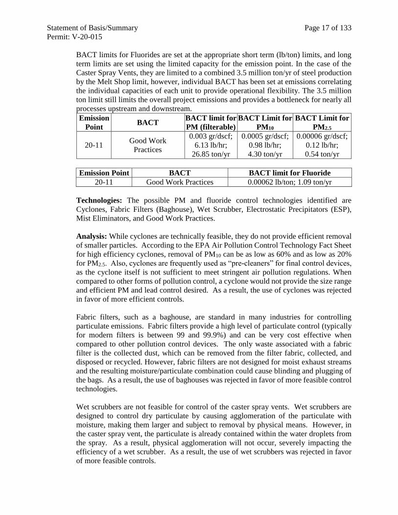
BACT limits for Fluorides are set at the appropriate short term (lb/ton) limits, and long
term limits are set using the limited capacity for the emission point. In the case of the
Caster Spray Vents, they are limited to a combined 3.5 million ton/yr of steel production
by the Melt Shop limit, however, individual BACT has been set at emissions correlating
the individual capacities of each unit to provide operational flexibility. The 3.5 million
ton limit still limits the overall project emissions and provides a bottleneck for nearly all
processes upstream and downstream.
Emission
Point BACT
BACT limit for
PM (filterable)
BACT Limit for
PM10
BACT Limit for
PM2.5
20-11 Good Work
Practices
0.003 gr/dscf;
6.13 lb/hr;
26.85 ton/yr
0.0005 gr/dscf;
0.98 lb/hr;
4.30 ton/yr
0.00006 gr/dscf;
0.12 lb/hr;
0.54 ton/yr
Emission Point BACT BACT limit for Fluoride
20-11 Good Work Practices 0.00062 lb/ton; 1.09 ton/yr
Technologies: The possible PM and fluoride control technologies identified are
Cyclones, Fabric Filters (Baghouse), Wet Scrubber, Electrostatic Precipitators (ESP),
Mist Eliminators, and Good Work Practices.
Analysis: While cyclones are technically feasible, they do not provide efficient removal
of smaller particles. According to the EPA Air Pollution Control Technology Fact Sheet
for high efficiency cyclones, removal of PM10 can be as low as 60% and as low as 20%
for PM2.5. Also, cyclones are frequently used as “pre-cleaners” for final control devices,
as the cyclone itself is not sufficient to meet stringent air pollution regulations. When
compared to other forms of pollution control, a cyclone would not provide the size range
and efficient PM and lead control desired. As a result, the use of cyclones was rejected
in favor of more efficient controls.
Fabric filters, such as a baghouse, are standard in many industries for controlling
particulate emissions. Fabric filters provide a high level of particulate control (typically
for modern filters is between 99 and 99.9%) and can be very cost effective when
compared to other pollution control devices. The only waste associated with a fabric
filter is the collected dust, which can be removed from the filter fabric, collected, and
disposed or recycled. However, fabric filters are not designed for moist exhaust streams
and the resulting moisture/particulate combination could cause blinding and plugging of
the bags. As a result, the use of baghouses was rejected in favor of more feasible control
technologies.
Wet scrubbers are not feasible for control of the caster spray vents. Wet scrubbers are
designed to control dry particulate by causing agglomeration of the particulate with
moisture, making them larger and subject to removal by physical means. However, in
the caster spray vent, the particulate is already contained within the water droplets from
the spray. As a result, physical agglomeration will not occur, severely impacting the
efficiency of a wet scrubber. As a result, the use of wet scrubbers was rejected in favor
of more feasible controls.
Statement of Basis/Summary Page 18 of 133
Permit: V-20-015
ESPs are efficient collectors and can treat large volumes of gas with low pressure drops.
An ESP can operate over a wide range of temperatures and dry ESPs have a relatively
low operating cost. Disadvantages of ESPs include high capital (building and installation)
costs, large space requirements, and variable efficiency depending on particle resistivity.
Wet ESPs have higher operating costs, due to water use and increased power
requirements, and creates a need for wastewater treatment. As a result, the use of an ESP
was rejected in favor of a more cost-effective technology.
Mist eliminators are designed to control aerosols and fine or condensable particulate
emissions. Fiber bed mats are often sprayed with scrubbing liquid so particles can be
collected by deposition on droplets and fiber bed mats. Waste gas streams are often
cooled before entering fiber-bed filters to condense as much liquid as possible and to
increase the size of the existing aerosol particles through condensation. According to the
EPA Pollution Control Technology Fact Sheet for mist eliminators, the minimum inlet
pollutant loading for a mist eliminator to be feasible is 0.1 gr/dscf, which is well above
the concentration being emitted by the spray caster vents (0.000061 gr/dscf to 0.0030
gr/dscf). As a result, the use of mist eliminators was rejected in favor of more feasible
control technologies.
Good work practices, such as periodic inspections to ensure equipment is in proper
working order, are both feasible and economical. As a result, the use of good work
practices is chosen as the appropriate BACT for the caster spray vents.
BACT limits for the caster spray vents has been set based upon grain loading for
particulate emissions and approved emission factors and known throughputs for fluoride
emissions.
Continuous compliance for the caster spray vents will demonstrated by implementing
written operating instructions and procedures that specify good operating and
maintenance practices (including tracking material usage and employing a preventative
maintenance programs), in addition to performing monthly operational status inspections
of the equipment.
Melt Shop #2 Scrap Bucket Charge (EP 20-15)
Emissions from this process will occur within the Melt Shop building, and will be
captured by the canopy hooding for Baghouse #3. Accordingly, no separate emission
limitation has been set, however, a Good Work Practices plan for this intermittent process
is appropriate and has been included in the permit, which should include qualitative
monitoring of emissions when loading the scrap bucket to ensure effective capture is
occurring.
3. Melt Shop #2 (EU 20) & Hot Rolling Mill (EU 02): Combustion Units
Note that due to the similar nature of all of the following emission points, i.e. direct-fired
natural gas combustion equipment, the particulate BACT for these emission points,
originating from two different units, i.e. Melt Shop #2 (EU 20) and Hot Rolling Mill (EU
02), are discussed together. This grouping is used throughout the BACT Analyses
pollutant-specific sections as applicable. Where there has been no change to the original
BACT analysis, it is not repeated here.
Statement of Basis/Summary Page 19 of 133
Permit: V-20-015
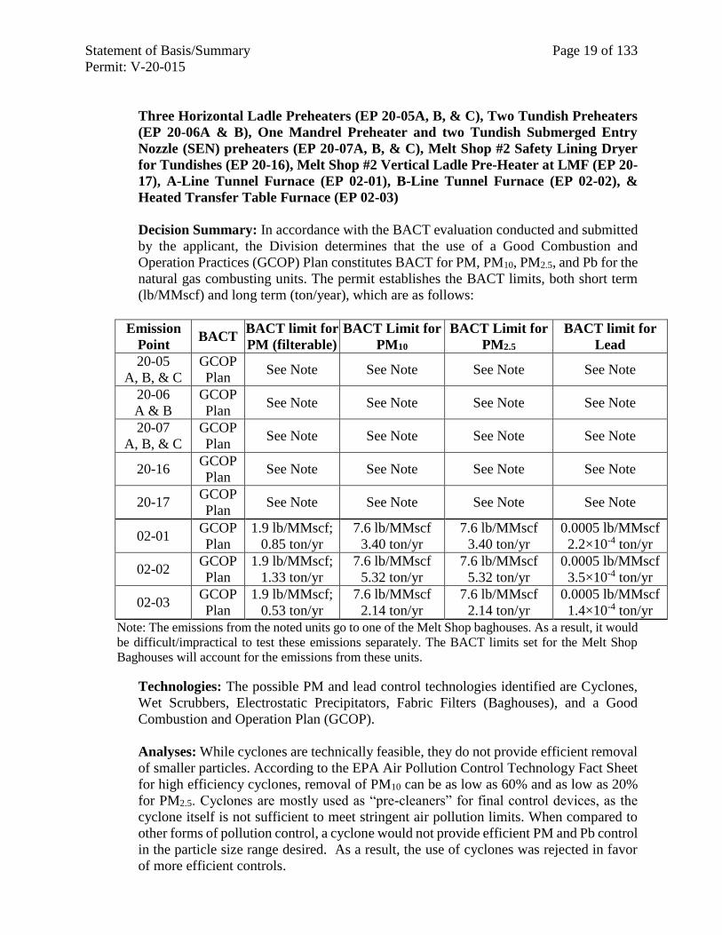
Three Horizontal Ladle Preheaters (EP 20-05A, B, & C), Two Tundish Preheaters
(EP 20-06A & B), One Mandrel Preheater and two Tundish Submerged Entry
Nozzle (SEN) preheaters (EP 20-07A, B, & C), Melt Shop #2 Safety Lining Dryer
for Tundishes (EP 20-16), Melt Shop #2 Vertical Ladle Pre-Heater at LMF (EP 20-
17), A-Line Tunnel Furnace (EP 02-01), B-Line Tunnel Furnace (EP 02-02), &
Heated Transfer Table Furnace (EP 02-03)
Decision Summary: In accordance with the BACT evaluation conducted and submitted
by the applicant, the Division determines that the use of a Good Combustion and
Operation Practices (GCOP) Plan constitutes BACT for PM, PM10, PM2.5, and Pb for the
natural gas combusting units. The permit establishes the BACT limits, both short term
(lb/MMscf) and long term (ton/year), which are as follows:
Emission
Point BACT
BACT limit for
PM (filterable)
BACT Limit for
PM10
BACT Limit for
PM2.5
BACT limit for
Lead
20-05
A, B, & C
GCOP
Plan See Note See Note See Note See Note
20-06
A & B
GCOP
Plan See Note See Note See Note See Note
20-07
A, B, & C
GCOP
Plan See Note See Note See Note See Note
20-16 GCOP
Plan See Note See Note See Note See Note
20-17 GCOP
Plan See Note See Note See Note See Note
02-01 GCOP
Plan
1.9 lb/MMscf;
0.85 ton/yr
7.6 lb/MMscf
3.40 ton/yr
7.6 lb/MMscf
3.40 ton/yr
0.0005 lb/MMscf
2.2×10⁻⁴ ton/yr
02-02 GCOP
Plan
1.9 lb/MMscf;
1.33 ton/yr
7.6 lb/MMscf
5.32 ton/yr
7.6 lb/MMscf
5.32 ton/yr
0.0005 lb/MMscf
3.5×10⁻⁴ ton/yr
02-03 GCOP
Plan
1.9 lb/MMscf;
0.53 ton/yr
7.6 lb/MMscf
2.14 ton/yr
7.6 lb/MMscf
2.14 ton/yr
0.0005 lb/MMscf
1.4×10⁻⁴ ton/yr
Note: The emissions from the noted units go to one of the Melt Shop baghouses. As a result, it would
be difficult/impractical to test these emissions separately. The BACT limits set for the Melt Shop
Baghouses will account for the emissions from these units.
Technologies: The possible PM and lead control technologies identified are Cyclones,
Wet Scrubbers, Electrostatic Precipitators, Fabric Filters (Baghouses), and a Good
Combustion and Operation Plan (GCOP).
Analyses: While cyclones are technically feasible, they do not provide efficient removal
of smaller particles. According to the EPA Air Pollution Control Technology Fact Sheet
for high efficiency cyclones, removal of PM10 can be as low as 60% and as low as 20%
for PM2.5. Cyclones are mostly used as “pre-cleaners” for final control devices, as the
cyclone itself is not sufficient to meet stringent air pollution limits. When compared to
other forms of pollution control, a cyclone would not provide efficient PM and Pb control
in the particle size range desired. As a result, the use of cyclones was rejected in favor
of more efficient controls.
Statement of Basis/Summary Page 20 of 133
Permit: V-20-015
Wet scrubbers, while technically feasible, have several disadvantages associated with
their use. This includes the need for wastewater treatment, creation of sludge requiring
disposal, and higher energy costs. Using a wet scrubber for the minor PM and Pb
emissions associated with natural gas combustion would be cost prohibitive.
ESPs are efficient collectors and can treat large volumes of gas with low pressure drops.
An ESP can operate over a wide range of temperatures and dry ESPs have a relatively
low operating cost. Disadvantages of ESPs include high capital (building and installation)
costs, large space requirements, and difficulty in controlling particles with high
resistivity. Wet ESPs have higher operating costs, due to water use and increased power
requirements, and creates a need for wastewater treatment. As a result, using an ESP for
the minor PM and Pb emissions associated with natural gas combustion would be cost
prohibitive.
A fabric filter, also known as a baghouse, is standard in the iron foundry industry for
controlling particulate emissions from a melt shop. Baghouses provide a high level of
particulate control (typical for modern filters is between 99 and 99.9%) and can be more
cost effective than several other available control types. The only waste associated with
fabric filter use is the collected dust. As discussed in Technologies for Particulate Control
and Lead, above, filters are cleaned, dust collected, and the waste disposed or recycled.
However, the addition of a baghouse would not be a cost effective control for removing
the small amounts of PM and lead emitted by the natural gas combusting units.
Although combustion of natural gas normally produces very little filterable PM and Pb,
combustion optimization ensures that even the small amount of particulate emitted is
minimized. This approach is technically feasible for any combustion process. For the
natural gas combusting equipment, installing add-on active controls to the natural gas
burning units is either impossible or impractical. However, even the small amount of
particulate from this equipment can be reduced through development of a GCOP Plan.
Ensuring complete combustion of the natural gas is both practical and economic for
emission control in this application.
BACT limitations are set based on projected emissions using approved emission factors
and known throughputs.
Initial compliance demonstration with BACT will be through development of a GCOP
plan within 90 days of equipment startup. Implementation of the GCOP plan and
monitoring, recording and reporting gas usage will provide continuous compliance
assurance for the subject equipment.
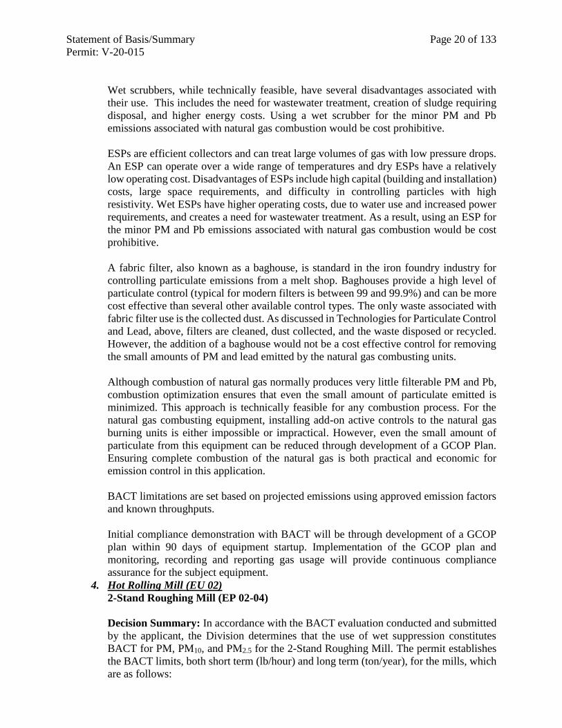
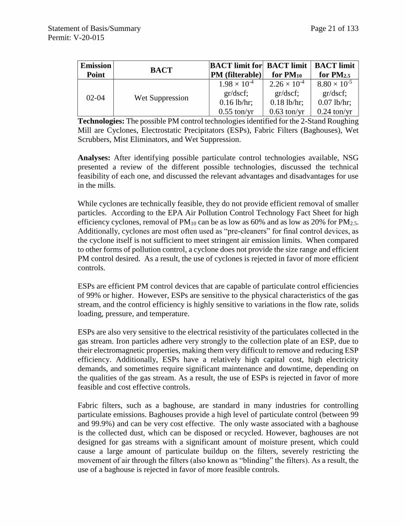
4. Hot Rolling Mill (EU 02)
2-Stand Roughing Mill (EP 02-04)
Decision Summary: In accordance with the BACT evaluation conducted and submitted
by the applicant, the Division determines that the use of wet suppression constitutes
BACT for PM, PM10, and PM2.5 for the 2-Stand Roughing Mill. The permit establishes
the BACT limits, both short term (lb/hour) and long term (ton/year), for the mills, which
are as follows:
Statement of Basis/Summary Page 21 of 133
Permit: V-20-015
Emission
Point BACT
BACT limit for
PM (filterable)
BACT limit
for PM10
BACT limit
for PM2.5
02-04 Wet Suppression
1.98 × 10⁻⁴
gr/dscf;
0.16 lb/hr;
0.55 ton/yr
2.26 × 10⁻⁴
gr/dscf;
0.18 lb/hr;
0.63 ton/yr
8.80 × 10⁻⁵
gr/dscf;
0.07 lb/hr;
0.24 ton/yr
Technologies: The possible PM control technologies identified for the 2-Stand Roughing
Mill are Cyclones, Electrostatic Precipitators (ESPs), Fabric Filters (Baghouses), Wet
Scrubbers, Mist Eliminators, and Wet Suppression.
Analyses: After identifying possible particulate control technologies available, NSG
presented a review of the different possible technologies, discussed the technical
feasibility of each one, and discussed the relevant advantages and disadvantages for use
in the mills.
While cyclones are technically feasible, they do not provide efficient removal of smaller
particles. According to the EPA Air Pollution Control Technology Fact Sheet for high
efficiency cyclones, removal of PM10 can be as low as 60% and as low as 20% for PM2.5.
Additionally, cyclones are most often used as “pre-cleaners” for final control devices, as
the cyclone itself is not sufficient to meet stringent air emission limits. When compared
to other forms of pollution control, a cyclone does not provide the size range and efficient
PM control desired. As a result, the use of cyclones is rejected in favor of more efficient
controls.
ESPs are efficient PM control devices that are capable of particulate control efficiencies
of 99% or higher. However, ESPs are sensitive to the physical characteristics of the gas
stream, and the control efficiency is highly sensitive to variations in the flow rate, solids
loading, pressure, and temperature.
ESPs are also very sensitive to the electrical resistivity of the particulates collected in the
gas stream. Iron particles adhere very strongly to the collection plate of an ESP, due to
their electromagnetic properties, making them very difficult to remove and reducing ESP
efficiency. Additionally, ESPs have a relatively high capital cost, high electricity
demands, and sometimes require significant maintenance and downtime, depending on
the qualities of the gas stream. As a result, the use of ESPs is rejected in favor of more
feasible and cost effective controls.
Fabric filters, such as a baghouse, are standard in many industries for controlling
particulate emissions. Baghouses provide a high level of particulate control (between 99
and 99.9%) and can be very cost effective. The only waste associated with a baghouse
is the collected dust, which can be disposed or recycled. However, baghouses are not
designed for gas streams with a significant amount of moisture present, which could
cause a large amount of particulate buildup on the filters, severely restricting the
movement of air through the filters (also known as “blinding” the filters). As a result, the
use of a baghouse is rejected in favor of more feasible controls.
Statement of Basis/Summary Page 22 of 133
Permit: V-20-015
While a wet scrubber would be technically feasible, it does not offer the high efficiencies
that can be achieved with other control technologies, with collection efficiencies as low
as 50% according to the EPA Air Pollution Control Technology Fact Sheet for wet
scrubbers. Wet scrubbers also come with disadvantages such as the need for wastewater
treatment, creation of sludge required disposal, and high energy costs. These
disadvantages make the use of a wet scrubber less efficient and less cost effective than
the use of a mist eliminator. In addition, industry literature did not have any examples of
wet scrubbers used in this type of service. As a result, the use of wet scrubbers is rejected
in favor of more efficient and cost effective controls.
Mist eliminators are designed to control aerosols and fine or condensable particulate
emissions. According to steel industry databases, mist eliminators are the most
commonly used and efficient controls for temper mills, cold reduction mills, and skin
pass mills. Because the inlet loading to a mist eliminator from the mill would be below
the minimum inlet loading required for mist eliminators to be effective, this technology
is considered technically infeasible.
Wet suppression suppresses particulate emissions by wetting particles, which causes
them to become heavy and settle, reducing the amount of airborne particulates. Wet
suppression is both feasible and economical for use on the 2-Stand Roughing Mill as
cooling water is already required for these units. As a result, wet suppression is chosen
as BACT for the 2-Stand Roughing Mill.
As configured, the proposed 2-Stand Roughing Mill design limits PM/PM10/PM2.5
emissions in a manner consistent with current industry standards.
Initial and continuous compliance is demonstrated through monitoring, recording and
reporting throughputs for the equipment.
Rolling Mill Inspection Line Plasma Cutter (EP 02-07)
Decision Summary: In accordance with the BACT evaluation conducted and submitted
by the applicant, the Division determines that the use of a fabric filter (baghouse)
constitutes BACT for PM, PM10, and PM2.5 for the Hot Rolling Mill Plasma Cutter. No
Pb emissions are associated with this equipment. The permit establishes the BACT limits,
which are as follows:
Emission
Point BACT
BACT Limit for
PM (filterable)
BACT Limit
for PM10
BACT Limit
for PM2.5
02-07 Baghouse 0.04 lb/hr;
0.19 ton/yr
0.04 lb/hr;
0.19 ton/yr
0.04 lb/hr;
0.19 ton/yr
Technologies: The possible PM control technologies identified are Cyclones, Wet
Scrubbers, Electrostatic Precipitators, and Fabric Filters.
Analyses: While cyclones are technically feasible, they do not provide efficient removal
of smaller particles. According to the EPA Air Pollution Control Technology Fact Sheet
for high efficiency cyclones, removal of PM10 can be as low as 60% and as low as 20%
Statement of Basis/Summary Page 23 of 133
Permit: V-20-015
for PM2.5. Cyclones are frequently used as “pre-cleaners” for final control devices, as the
cyclone itself is not efficient enough to meet stringent emission limits. When compared
with other forms of pollution control, a cyclone would not provide efficient enough
control of the range of particle sizes emitted from these units. As a result, the use of
cyclones is rejected in favor of more efficient controls.
Wet scrubbers, while technically feasible, have several disadvantages associated with
their use. This includes the need for wastewater treatment, creation of sludge requiring
disposal, and higher energy costs. As a result, using a wet scrubber in this application
would be cost prohibitive.
ESPs are efficient collectors and can treat large volumes of gas with low pressure drops.
An ESP can operate over a wide range of temperatures and dry ESPs have a relatively
low operating cost. Disadvantages of ESPs include high capital (building and installation)
costs, large space requirements, and difficulty in controlling particles with high
resistivity. Wet ESPs have higher operating costs, due to water use and increased power
requirements, and creates a need for wastewater treatment. As a result, using an ESP
would not be cost effective.
Fabric filters, such as a baghouse, are standard in many industries for controlling
particulate emissions. Fabric filters provide a high level of particulate control (typically
for modern filters is between 99 and 99.9%) and can be very cost effective when
compared to other pollution control devices. The only waste associated with a fabric filter
is the collected dust, which is removed from the filter fabric, collected, and disposed or
recycled. As a result, the use of a fabric filter (a baghouse) is chosen as the appropriate
BACT for the Rolling Mill Inspection Line Plasma Cutter.
BACT limitations are established based on projected emissions using approved emission
factors and known throughputs.
Initial compliance for the plasma cutter is demonstrated through installing and operating
a baghouse certified by the manufacturer to meet the BACT limits specified, above.
Continuous compliance is demonstrated through monitoring, recording and reporting
throughputs for the equipment and the control device.
5. Cooling Towers (EU 03)
Laminar Cooling Tower-Hot Mill Cells (EP 03-09), Direct Cooling Tower-Caster &
Roughing Mill Cells (EP 03-10), Melt Shop #2 Indirect Cooling Tower (EP 03-11),
Air Separation Plant Cooling Tower (EP 03-13), and DCW Auxiliary Cooling
Tower (EP 03-14)
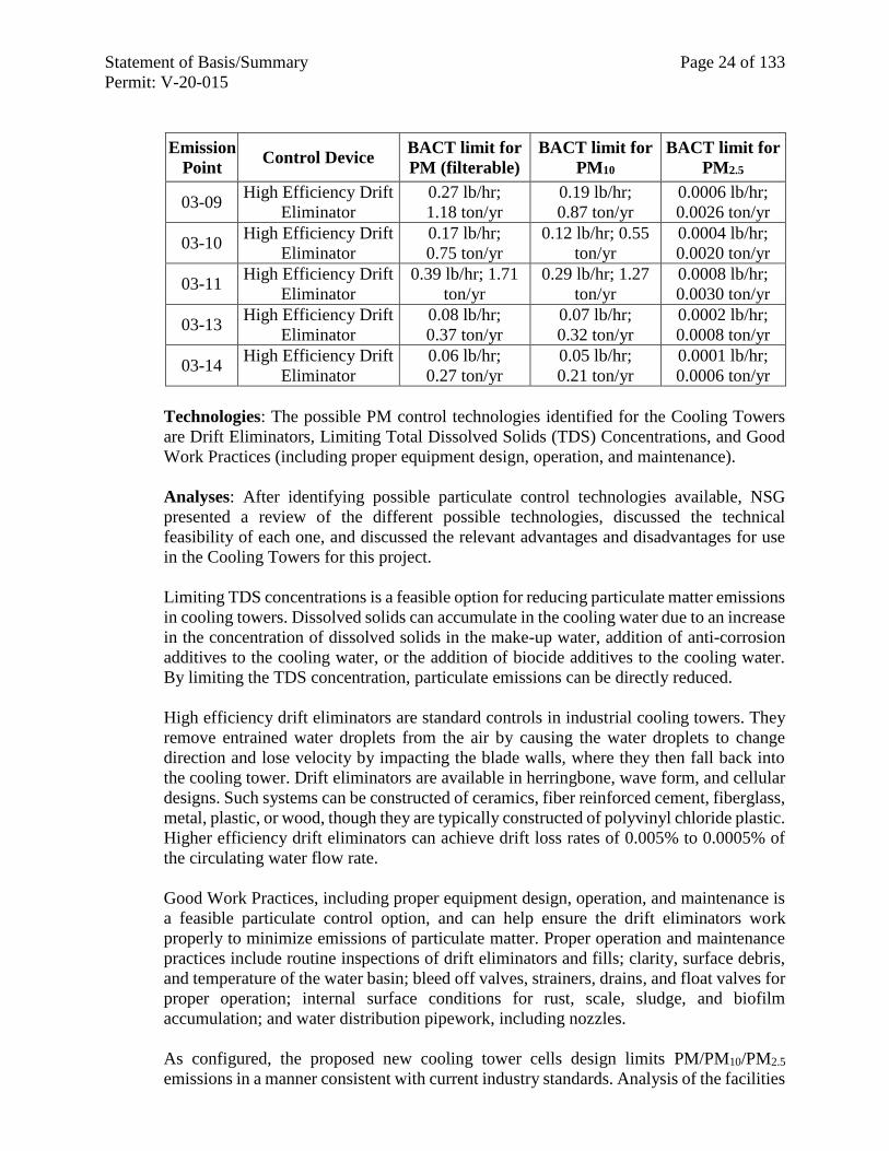
Decision Summary: In accordance with the BACT evaluation conducted and submitted
by the applicant, the Division determines that the use of high efficiency drift eliminators
constitutes BACT for PM, PM10, and PM2.5 for the cooling towers in Emission Group 03.
The permit establishes BACT emission limitations, both short term (lb/hr) and long term
(ton/yr) for each cooling tower, as well as water flow rate limitations, and total dissolved
solids limitations. To ensure compliance with these limitations, the permit requires
recordkeeping and monitoring.
Statement of Basis/Summary Page 24 of 133
Permit: V-20-015
Emission
Point Control Device
BACT limit for
PM (filterable)
BACT limit for
PM10
BACT limit for
PM2.5
03-09 High Efficiency Drift
Eliminator
0.27 lb/hr;
1.18 ton/yr
0.19 lb/hr;
0.87 ton/yr
0.0006 lb/hr;
0.0026 ton/yr
03-10 High Efficiency Drift
Eliminator
0.17 lb/hr;
0.75 ton/yr
0.12 lb/hr; 0.55
ton/yr
0.0004 lb/hr;
0.0020 ton/yr
03-11 High Efficiency Drift
Eliminator
0.39 lb/hr; 1.71
ton/yr
0.29 lb/hr; 1.27
ton/yr
0.0008 lb/hr;
0.0030 ton/yr
03-13 High Efficiency Drift
Eliminator
0.08 lb/hr;
0.37 ton/yr
0.07 lb/hr;
0.32 ton/yr
0.0002 lb/hr;
0.0008 ton/yr
03-14 High Efficiency Drift
Eliminator
0.06 lb/hr;
0.27 ton/yr
0.05 lb/hr;
0.21 ton/yr
0.0001 lb/hr;
0.0006 ton/yr
Technologies: The possible PM control technologies identified for the Cooling Towers
are Drift Eliminators, Limiting Total Dissolved Solids (TDS) Concentrations, and Good
Work Practices (including proper equipment design, operation, and maintenance).
Analyses: After identifying possible particulate control technologies available, NSG
presented a review of the different possible technologies, discussed the technical
feasibility of each one, and discussed the relevant advantages and disadvantages for use
in the Cooling Towers for this project.
Limiting TDS concentrations is a feasible option for reducing particulate matter emissions
in cooling towers. Dissolved solids can accumulate in the cooling water due to an increase
in the concentration of dissolved solids in the make-up water, addition of anti-corrosion
additives to the cooling water, or the addition of biocide additives to the cooling water.
By limiting the TDS concentration, particulate emissions can be directly reduced.
High efficiency drift eliminators are standard controls in industrial cooling towers. They
remove entrained water droplets from the air by causing the water droplets to change
direction and lose velocity by impacting the blade walls, where they then fall back into
the cooling tower. Drift eliminators are available in herringbone, wave form, and cellular
designs. Such systems can be constructed of ceramics, fiber reinforced cement, fiberglass,
metal, plastic, or wood, though they are typically constructed of polyvinyl chloride plastic.
Higher efficiency drift eliminators can achieve drift loss rates of 0.005% to 0.0005% of
the circulating water flow rate.
Good Work Practices, including proper equipment design, operation, and maintenance is
a feasible particulate control option, and can help ensure the drift eliminators work
properly to minimize emissions of particulate matter. Proper operation and maintenance
practices include routine inspections of drift eliminators and fills; clarity, surface debris,
and temperature of the water basin; bleed off valves, strainers, drains, and float valves for
proper operation; internal surface conditions for rust, scale, sludge, and biofilm
accumulation; and water distribution pipework, including nozzles.
As configured, the proposed new cooling tower cells design limits PM/PM10/PM2.5
emissions in a manner consistent with current industry standards. Analysis of the facilities
Statement of Basis/Summary Page 25 of 133
Permit: V-20-015
in the RBLC database demonstrates that virtually every cooling tower across the
metallurgical industry utilizes high efficiency drift eliminators as a control method.
BACT limits for the cooling towers are set using drift rates that are equal to or more
stringent than BACT limits for similar cooling towers, as well as historical data collected
from existing cooling towers regarding the TDS concentrations, and water flow rates as
designed.
Compliance for the cooling towers is demonstrated through weekly monitoring of the TDS
concentration or conductivity of the cooling towers’ water, the water throughput of each
tower, as well as the common header pressure for each connected pump. Records must be
kept for all monitored parameters, as well as of maintenance conducted on the cooling
towers and mist eliminators, Safety Data Sheets of any water treatment chemicals used,
and manufacturer provided pump curves.
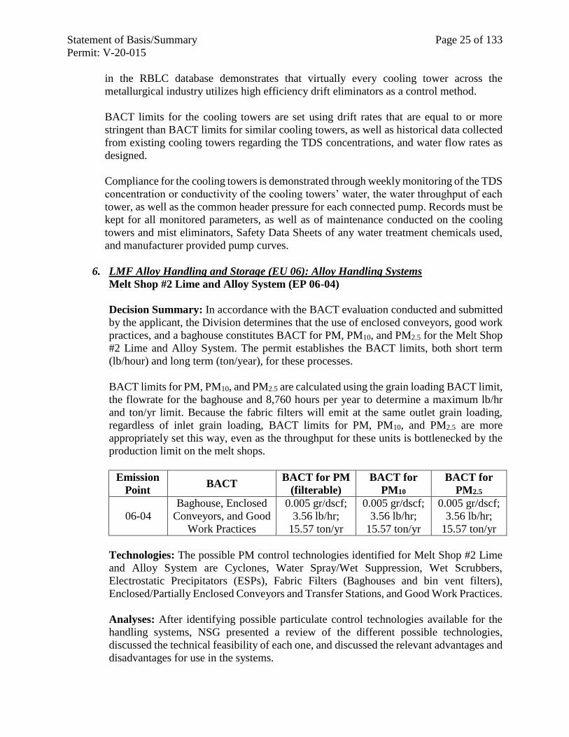
6. LMF Alloy Handling and Storage (EU 06): Alloy Handling Systems
Melt Shop #2 Lime and Alloy System (EP 06-04)
Decision Summary: In accordance with the BACT evaluation conducted and submitted
by the applicant, the Division determines that the use of enclosed conveyors, good work
practices, and a baghouse constitutes BACT for PM, PM10, and PM2.5 for the Melt Shop
#2 Lime and Alloy System. The permit establishes the BACT limits, both short term
(lb/hour) and long term (ton/year), for these processes.
BACT limits for PM, PM10, and PM2.5 are calculated using the grain loading BACT limit,
the flowrate for the baghouse and 8,760 hours per year to determine a maximum lb/hr
and ton/yr limit. Because the fabric filters will emit at the same outlet grain loading,
regardless of inlet grain loading, BACT limits for PM, PM10, and PM2.5 are more
appropriately set this way, even as the throughput for these units is bottlenecked by the
production limit on the melt shops.
Emission
Point BACT
BACT for PM
(filterable)
BACT for
PM10
BACT for
PM2.5
06-04
Baghouse, Enclosed
Conveyors, and Good
Work Practices
0.005 gr/dscf;
3.56 lb/hr;
15.57 ton/yr
0.005 gr/dscf;
3.56 lb/hr;
15.57 ton/yr
0.005 gr/dscf;
3.56 lb/hr;
15.57 ton/yr
Technologies: The possible PM control technologies identified for Melt Shop #2 Lime
and Alloy System are Cyclones, Water Spray/Wet Suppression, Wet Scrubbers,
Electrostatic Precipitators (ESPs), Fabric Filters (Baghouses and bin vent filters),
Enclosed/Partially Enclosed Conveyors and Transfer Stations, and Good Work Practices.
Analyses: After identifying possible particulate control technologies available for the
handling systems, NSG presented a review of the different possible technologies,
discussed the technical feasibility of each one, and discussed the relevant advantages and
disadvantages for use in the systems.
Statement of Basis/Summary Page 26 of 133
Permit: V-20-015
While cyclones are technically feasible controls for these systems, they do not provide
efficient removal of smaller particles. According to the EPA Air Pollution Control
Technology Fact Sheet for high efficiency cyclones, removal of PM10 can be as low as
60 % and as low as 20 % for PM2.5. Cyclones are as “pre-cleaners” for final control
devices, as the cyclone itself is not efficient enough to meet stringent air emission limits.
When compared with other forms of pollution control, a cyclone would not provide
sufficient control of the range of particle sizes emitted from these units. As a result, the
use of cyclones is rejected in favor of more efficient controls.
Wet sprays and wet suppression are not technically feasible for the control particulate
emissions from the alloy handling systems, as these systems are designed for
transport/storage of dry materials. Using liquids would create wet materials that may
obstruct equipment, requiring excessive maintenance and causing equipment wear. As a
result, the use of wet sprays and wet suppression is rejected in favor of more technically
feasible controls.
While a wet scrubber would be technically feasible, it does not offer the high efficiencies
of a baghouse or bin vent filter. Collection efficiencies are as low as 50 % according to
the U.S. EPA Air Pollution Control Technology Fact Sheet for Wet Scrubbers. Wet
scrubbers also come with disadvantages including the need for wastewater treatment, the
creation of sludge requiring disposal, and higher than average control energy costs. This
makes using a wet scrubber less efficient and less cost effective than the use of a
baghouse or bin vent filter. As a result, the use of wet scrubbers is rejected in favor of
more efficient and cost effective controls.
ESPs are efficient PM control devices that are capable of particulate control efficiencies
of 99 % or greater. However, ESPs operation is affected by the physical characteristics
of the gas stream, and the control efficiency is highly susceptible to variations in the flow
rate, solids loading, pressure, and temperature. ESPs are also very sensitive to the
electrical resistivity of the particulates in the gas stream. Additionally, ESPs have a
relatively high capital cost, high electricity demands, and sometimes require significant
maintenance depending on the qualities of the gas stream, which can result in extended
downtime. As a result, the use of ESPs is rejected in favor of more feasible and cost
effective controls.
Fabric filters, such as a baghouse or a bin vent filter, are standard in many industries for
controlling particulates. Fabric filters provide a high level of particulate control, between
99 and 99.9% for typical modern filters, and can be very cost effective when compared
to other pollution control devices. The only waste associated with fabric filter use is the
collected dust. As discussed in Technologies for Particulate Control and Lead, above,
filters are cleaned, dust collected, and the waste disposed or recycled.
A baghouse has been chosen as the appropriate BACT for the Melt Shop #2 Lime and
Alloy system. Additionally, since the material handling systems move dry materials
through a system of conveyors and transfers, enclosed and/or partially enclosing the
moving devices prevents airflow from lifting particulate matter and causing dusts.
Designed with minimal material drop height, the enclosed transfer stations also reduce
the chance of particulate generation. These methods of handling are common for dry
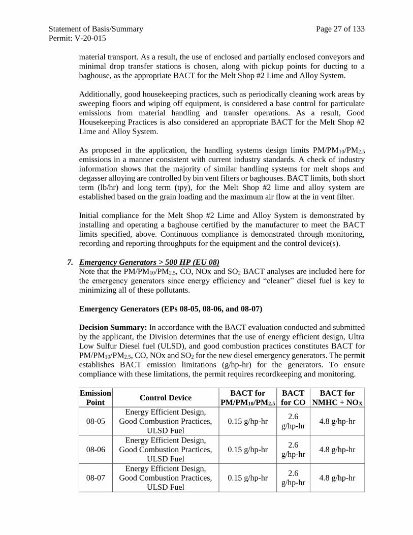
Statement of Basis/Summary Page 27 of 133
Permit: V-20-015
material transport. As a result, the use of enclosed and partially enclosed conveyors and
minimal drop transfer stations is chosen, along with pickup points for ducting to a
baghouse, as the appropriate BACT for the Melt Shop #2 Lime and Alloy System.
Additionally, good housekeeping practices, such as periodically cleaning work areas by
sweeping floors and wiping off equipment, is considered a base control for particulate
emissions from material handling and transfer operations. As a result, Good
Housekeeping Practices is also considered an appropriate BACT for the Melt Shop #2
Lime and Alloy System.
As proposed in the application, the handling systems design limits PM/PM10/PM2.5
emissions in a manner consistent with current industry standards. A check of industry
information shows that the majority of similar handling systems for melt shops and
degasser alloying are controlled by bin vent filters or baghouses. BACT limits, both short
term (lb/hr) and long term (tpy), for the Melt Shop #2 lime and alloy system are
established based on the grain loading and the maximum air flow at the in vent filter.
Initial compliance for the Melt Shop #2 Lime and Alloy System is demonstrated by
installing and operating a baghouse certified by the manufacturer to meet the BACT
limits specified, above. Continuous compliance is demonstrated through monitoring,
recording and reporting throughputs for the equipment and the control device(s).
7. Emergency Generators > 500 HP (EU 08)
Note that the PM/PM10/PM2.5, CO, NOx and SO2 BACT analyses are included here for
the emergency generators since energy efficiency and “cleaner” diesel fuel is key to
minimizing all of these pollutants.
Emergency Generators (EPs 08-05, 08-06, and 08-07)
Decision Summary: In accordance with the BACT evaluation conducted and submitted
by the applicant, the Division determines that the use of energy efficient design, Ultra
Low Sulfur Diesel fuel (ULSD), and good combustion practices constitutes BACT for
PM/PM10/PM2.5, CO, NOx and SO2 for the new diesel emergency generators. The permit
establishes BACT emission limitations (g/hp-hr) for the generators. To ensure
compliance with these limitations, the permit requires recordkeeping and monitoring.
Emission
Point Control Device
BACT for
PM/PM10/PM2.5
BACT
for CO
BACT for
NMHC + NOX
08-05
Energy Efficient Design,
Good Combustion Practices,
ULSD Fuel
0.15 g/hp-hr 2.6
g/hp-hr 4.8 g/hp-hr
08-06
Energy Efficient Design,
Good Combustion Practices,
ULSD Fuel
0.15 g/hp-hr 2.6
g/hp-hr 4.8 g/hp-hr
08-07
Energy Efficient Design,
Good Combustion Practices,
ULSD Fuel
0.15 g/hp-hr 2.6
g/hp-hr 4.8 g/hp-hr
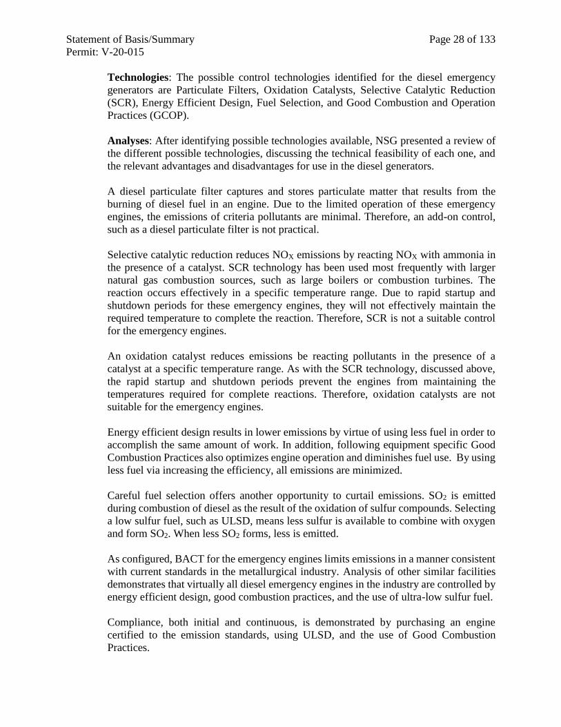
Statement of Basis/Summary Page 28 of 133
Permit: V-20-015
Technologies: The possible control technologies identified for the diesel emergency
generators are Particulate Filters, Oxidation Catalysts, Selective Catalytic Reduction
(SCR), Energy Efficient Design, Fuel Selection, and Good Combustion and Operation
Practices (GCOP).
Analyses: After identifying possible technologies available, NSG presented a review of
the different possible technologies, discussing the technical feasibility of each one, and
the relevant advantages and disadvantages for use in the diesel generators.
A diesel particulate filter captures and stores particulate matter that results from the
burning of diesel fuel in an engine. Due to the limited operation of these emergency
engines, the emissions of criteria pollutants are minimal. Therefore, an add-on control,
such as a diesel particulate filter is not practical.
Selective catalytic reduction reduces NOX emissions by reacting NOX with ammonia in
the presence of a catalyst. SCR technology has been used most frequently with larger
natural gas combustion sources, such as large boilers or combustion turbines. The
reaction occurs effectively in a specific temperature range. Due to rapid startup and
shutdown periods for these emergency engines, they will not effectively maintain the
required temperature to complete the reaction. Therefore, SCR is not a suitable control
for the emergency engines.
An oxidation catalyst reduces emissions be reacting pollutants in the presence of a
catalyst at a specific temperature range. As with the SCR technology, discussed above,
the rapid startup and shutdown periods prevent the engines from maintaining the
temperatures required for complete reactions. Therefore, oxidation catalysts are not
suitable for the emergency engines.
Energy efficient design results in lower emissions by virtue of using less fuel in order to
accomplish the same amount of work. In addition, following equipment specific Good
Combustion Practices also optimizes engine operation and diminishes fuel use. By using
less fuel via increasing the efficiency, all emissions are minimized.
Careful fuel selection offers another opportunity to curtail emissions. SO2 is emitted
during combustion of diesel as the result of the oxidation of sulfur compounds. Selecting
a low sulfur fuel, such as ULSD, means less sulfur is available to combine with oxygen
and form SO2. When less SO2 forms, less is emitted.
As configured, BACT for the emergency engines limits emissions in a manner consistent
with current standards in the metallurgical industry. Analysis of other similar facilities
demonstrates that virtually all diesel emergency engines in the industry are controlled by
energy efficient design, good combustion practices, and the use of ultra-low sulfur fuel.
Compliance, both initial and continuous, is demonstrated by purchasing an engine
certified to the emission standards, using ULSD, and the use of Good Combustion
Practices.
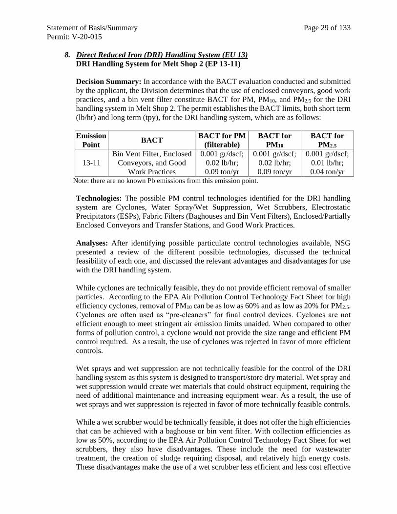
Statement of Basis/Summary Page 29 of 133
Permit: V-20-015
8. Direct Reduced Iron (DRI) Handling System (EU 13)
DRI Handling System for Melt Shop 2 (EP 13-11)
Decision Summary: In accordance with the BACT evaluation conducted and submitted
by the applicant, the Division determines that the use of enclosed conveyors, good work
practices, and a bin vent filter constitute BACT for PM, PM10, and PM2.5 for the DRI
handling system in Melt Shop 2. The permit establishes the BACT limits, both short term
(lb/hr) and long term (tpy), for the DRI handling system, which are as follows:
Emission
Point BACT
BACT for PM
(filterable)
BACT for
PM10
BACT for
PM2.5
13-11
Bin Vent Filter, Enclosed
Conveyors, and Good
Work Practices
0.001 gr/dscf;
0.02 lb/hr;
0.09 ton/yr
0.001 gr/dscf;
0.02 lb/hr;
0.09 ton/yr
0.001 gr/dscf;
0.01 lb/hr;
0.04 ton/yr Note: there are no known Pb emissions from this emission point.
Technologies: The possible PM control technologies identified for the DRI handling
system are Cyclones, Water Spray/Wet Suppression, Wet Scrubbers, Electrostatic
Precipitators (ESPs), Fabric Filters (Baghouses and Bin Vent Filters), Enclosed/Partially
Enclosed Conveyors and Transfer Stations, and Good Work Practices.
Analyses: After identifying possible particulate control technologies available, NSG
presented a review of the different possible technologies, discussed the technical
feasibility of each one, and discussed the relevant advantages and disadvantages for use
with the DRI handling system.
While cyclones are technically feasible, they do not provide efficient removal of smaller
particles. According to the EPA Air Pollution Control Technology Fact Sheet for high
efficiency cyclones, removal of PM10 can be as low as 60% and as low as 20% for PM2.5.
Cyclones are often used as “pre-cleaners” for final control devices. Cyclones are not
efficient enough to meet stringent air emission limits unaided. When compared to other
forms of pollution control, a cyclone would not provide the size range and efficient PM
control required. As a result, the use of cyclones was rejected in favor of more efficient
controls.
Wet sprays and wet suppression are not technically feasible for the control of the DRI
handling system as this system is designed to transport/store dry material. Wet spray and
wet suppression would create wet materials that could obstruct equipment, requiring the
need of additional maintenance and increasing equipment wear. As a result, the use of
wet sprays and wet suppression is rejected in favor of more technically feasible controls.
While a wet scrubber would be technically feasible, it does not offer the high efficiencies
that can be achieved with a baghouse or bin vent filter. With collection efficiencies as
low as 50%, according to the EPA Air Pollution Control Technology Fact Sheet for wet
scrubbers, they also have disadvantages. These include the need for wastewater
treatment, the creation of sludge requiring disposal, and relatively high energy costs.
These disadvantages make the use of a wet scrubber less efficient and less cost effective
Statement of Basis/Summary Page 30 of 133
Permit: V-20-015
than the use of a baghouse or bin vent filter. As a result, the use of wet scrubbers is
rejected in favor of more efficient and cost effective controls.
ESPs are efficient PM control devices that are capable of particulate control efficiencies
of 99% or higher. However, ESPs are sensitive to the physical characteristics of the gas
stream, and the control efficiency is highly sensitive to variations in the flow rate, solids
loading, pressure, and temperature. ESPs are also very sensitive to the electrical
resistivity of the particulates to be collected in the gas stream. Iron particles adhere very
strongly to the collection plate of an ESP due to their electromagnetic properties, making
them very difficult to remove, and thereby reducing the efficiency of the ESP.
Additionally, ESPs have a relatively high capital cost, high electricity demands, and
sometimes require significant maintenance and downtime depending on the qualities of
the gas stream. As a result, the use of ESPs is rejected in favor of more feasible and cost
effective controls.
Fabric filters, such as a baghouse or bin vent filter, are standard in many industries for
controlling particulate emissions. Fabric filters provide a high level of particulate control
(typically for modern filters, control is between 99 % and 99.9%) and can be very cost
effective when compared to other pollution control devices. The only waste associated
with a fabric filter is the collected dust, which can be collected from the filter fabric and
then disposed or recycled. While a baghouse may seem a likely best control technology
from a search of industry standards, NSG proposes a lower BACT limit with the use of
bin vent filters. As a result, the use of a bin vent filter is chosen as the appropriate BACT
for the DRI handling system.
Enclosed and partially enclosed conveyors and transfer stations prevent airflow from
lifting particulate matter from raw materials as they are transported on a conveyor belt or
in a transfer station. Enclosed transfer stations are typically designed with minimal
material drop height to reduce the chance of particulate matter being generated by the
material being transferred. Enclosed and partially enclosed conveyors and transfer
stations are commonly used when dry materials are moved. As a result, the use of
enclosed and partially enclosed conveyors and transfer stations is chosen, along with a
bin vent filter, as the appropriate BACT for the DRI handling system.
Good housekeeping practices consist of periodically cleaning work areas (such as
sweeping floors) and equipment as a base control for particulate emissions from material
handling and transfer operations. By keeping dusts to a minimum, overall emissions of
particulate are reduced.
As a result, the use of good housekeeping practices is also chosen, along with a bin vent
filter and enclosed/partially enclosed conveyors and transfer stations, as the appropriate
BACT for the DRI handling system.
As configured, the DRI handling system design limits PM/PM10/PM2.5 emissions in a
manner consistent with current industry standards. According to industry databases, the
majority of DRI handling systems are controlled by a fabric filter.
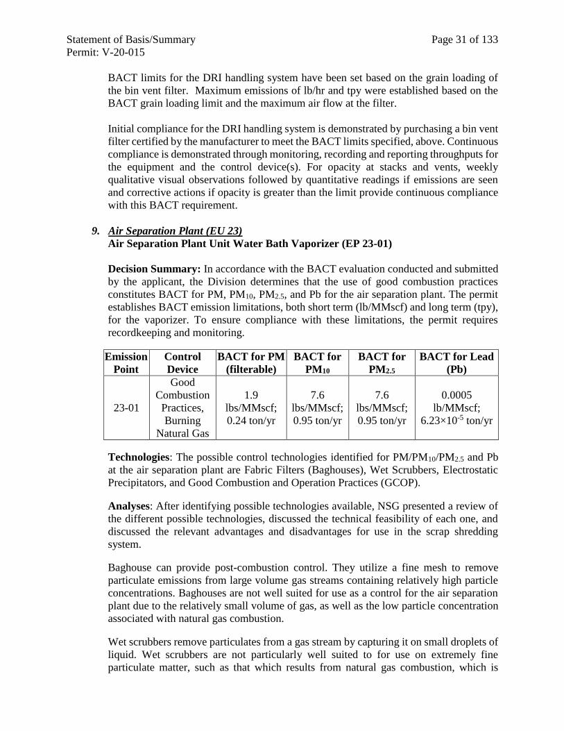
Statement of Basis/Summary Page 31 of 133
Permit: V-20-015
BACT limits for the DRI handling system have been set based on the grain loading of
the bin vent filter. Maximum emissions of lb/hr and tpy were established based on the
BACT grain loading limit and the maximum air flow at the filter.
Initial compliance for the DRI handling system is demonstrated by purchasing a bin vent
filter certified by the manufacturer to meet the BACT limits specified, above. Continuous
compliance is demonstrated through monitoring, recording and reporting throughputs for
the equipment and the control device(s). For opacity at stacks and vents, weekly
qualitative visual observations followed by quantitative readings if emissions are seen
and corrective actions if opacity is greater than the limit provide continuous compliance
with this BACT requirement.
9. Air Separation Plant (EU 23)
Air Separation Plant Unit Water Bath Vaporizer (EP 23-01)
Decision Summary: In accordance with the BACT evaluation conducted and submitted
by the applicant, the Division determines that the use of good combustion practices
constitutes BACT for PM, PM10, PM2.5, and Pb for the air separation plant. The permit
establishes BACT emission limitations, both short term (lb/MMscf) and long term (tpy),
for the vaporizer. To ensure compliance with these limitations, the permit requires
recordkeeping and monitoring.
Emission
Point
Control
Device
BACT for PM
(filterable)
BACT for
PM10
BACT for
PM2.5
BACT for Lead
(Pb)
23-01
Good
Combustion
Practices,
Burning
Natural Gas
1.9
lbs/MMscf;
0.24 ton/yr
7.6
lbs/MMscf;
0.95 ton/yr
7.6
lbs/MMscf;
0.95 ton/yr
0.0005
lb/MMscf;
6.23×10⁻⁵ ton/yr
Technologies: The possible control technologies identified for PM/PM10/PM2.5 and Pb
at the air separation plant are Fabric Filters (Baghouses), Wet Scrubbers, Electrostatic
Precipitators, and Good Combustion and Operation Practices (GCOP).
Analyses: After identifying possible technologies available, NSG presented a review of
the different possible technologies, discussed the technical feasibility of each one, and
discussed the relevant advantages and disadvantages for use in the scrap shredding
system.
Baghouse can provide post-combustion control. They utilize a fine mesh to remove
particulate emissions from large volume gas streams containing relatively high particle
concentrations. Baghouses are not well suited for use as a control for the air separation
plant due to the relatively small volume of gas, as well as the low particle concentration
associated with natural gas combustion.
Wet scrubbers remove particulates from a gas stream by capturing it on small droplets of
liquid. Wet scrubbers are not particularly well suited to for use on extremely fine
particulate matter, such as that which results from natural gas combustion, which is
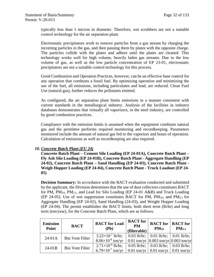
Statement of Basis/Summary Page 32 of 133
Permit: V-20-015
typically less than 1 micron in diameter. Therefore, wet scrubbers are not a suitable
control technology for the air separation plant.
Electrostatic precipitators work to remove particles from a gas stream by charging the
incoming particles in the gas, and then passing them by plates with the opposite charge.
The particles collide with the plates and adhere until the plates are cleaned. This
technology works well for high volume, heavily laden gas streams. Due to the low
volume of gas, as well as the low particle concentration of EP 23-01, electrostatic
precipitators are not a suitable control technology for this process.
Good Combustion and Operation Practices, however, can be an effective base control for
any operation that combusts a fossil fuel. By optimizing operation and minimizing the
use of the fuel, all emissions, including particulates and lead, are reduced. Clean Fuel
Use (natural gas), further reduces the pollutants emitted.
As configured, the air separation plant limits emissions in a manner consistent with
current standards in the metallurgical industry. Analysis of the facilities in industry
databases demonstrates that virtually all vaporizers, in the steel industry, are controlled
by good combustion practices.
Compliance with the emission limits is assumed when the equipment combusts natural
gas and the permittee performs required monitoring and recordkeeping. Parameters
monitored include the amount of natural gas fed to the vaporizer and hours of operation.
Calculation of emissions as well as recordkeeping are also required.
10. Concrete Batch Plant (EU 24)
Concrete Batch Plant – Cement Silo Loading (EP 24-01A), Concrete Batch Plant –
Fly Ash Silo Loading (EP 24-01B), Concrete Batch Plant - Aggregate Handling (EP
24-02), Concrete Batch Plant – Sand Handling (EP 24-03), Concrete Batch Plant -
Weigh Hopper Loading (EP 24-04), Concrete Batch Plant - Truck Loadout (EP 24-
05)
Decision Summary: In accordance with the BACT evaluation conducted and submitted
by the applicant, the Division determines that the use of dust collectors constitutes BACT
for PM, PM10, PM2.5, and Lead for Silo Loading (EP 24-01 A&B) and Truck Loading
(EP 24-05). Use of wet suppression constitutes BACT for PM, PM10, and PM2.5 for
Aggregate Handling (EP 24-02), Sand Handling (24-03), and Weight Hopper Loading
(EP 24-04). The permit establishes the BACT limits, both short term (lb/hr) and long
term (ton/year), for the Concrete Batch Plant, which are as follows:
Emission
Point BACT
BACT for Lead
(Pb)
BACT for
PM
(filterable)
BACT for
PM10
BACT for
PM2.5
24-01A Bin Vent Filter 3.22×10⁻⁷ lb/hr;
8.06×10⁻⁸ ton/yr
0.03 lb/hr;
0.01 ton/yr
0.01 lb/hr;
0.003 ton/yr
0.01 lb/hr;
0.003 ton/yr
24-01B Bin Vent Filter 2.71×10⁻⁶ lb/hr;
6.79×10⁻⁷ ton/yr
0.05 lb/hr;
0.01 ton/yr
0.03 lb/hr;
0.01 ton/yr
0.03 lb/hr;
0.01 ton/yr
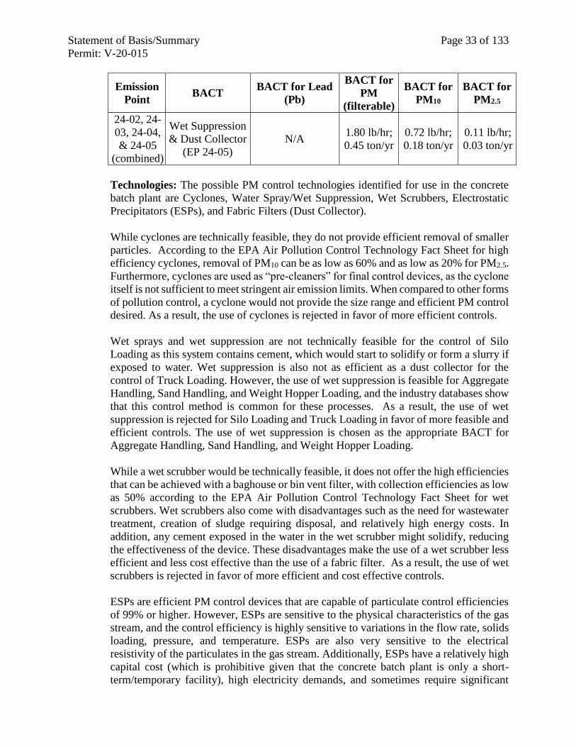
Statement of Basis/Summary Page 33 of 133
Permit: V-20-015
Emission
Point BACT
BACT for Lead
(Pb)
BACT for
PM
(filterable)
BACT for
PM10
BACT for
PM2.5
24-02, 24-
03, 24-04,
& 24-05
(combined)
Wet Suppression
& Dust Collector
(EP 24-05)
N/A 1.80 lb/hr;
0.45 ton/yr
0.72 lb/hr;
0.18 ton/yr
0.11 lb/hr;
0.03 ton/yr
Technologies: The possible PM control technologies identified for use in the concrete
batch plant are Cyclones, Water Spray/Wet Suppression, Wet Scrubbers, Electrostatic
Precipitators (ESPs), and Fabric Filters (Dust Collector).
While cyclones are technically feasible, they do not provide efficient removal of smaller
particles. According to the EPA Air Pollution Control Technology Fact Sheet for high
efficiency cyclones, removal of PM10 can be as low as 60% and as low as 20% for PM2.5.
Furthermore, cyclones are used as “pre-cleaners” for final control devices, as the cyclone
itself is not sufficient to meet stringent air emission limits. When compared to other forms
of pollution control, a cyclone would not provide the size range and efficient PM control
desired. As a result, the use of cyclones is rejected in favor of more efficient controls.
Wet sprays and wet suppression are not technically feasible for the control of Silo
Loading as this system contains cement, which would start to solidify or form a slurry if
exposed to water. Wet suppression is also not as efficient as a dust collector for the
control of Truck Loading. However, the use of wet suppression is feasible for Aggregate
Handling, Sand Handling, and Weight Hopper Loading, and the industry databases show
that this control method is common for these processes. As a result, the use of wet
suppression is rejected for Silo Loading and Truck Loading in favor of more feasible and
efficient controls. The use of wet suppression is chosen as the appropriate BACT for
Aggregate Handling, Sand Handling, and Weight Hopper Loading.
While a wet scrubber would be technically feasible, it does not offer the high efficiencies
that can be achieved with a baghouse or bin vent filter, with collection efficiencies as low
as 50% according to the EPA Air Pollution Control Technology Fact Sheet for wet
scrubbers. Wet scrubbers also come with disadvantages such as the need for wastewater
treatment, creation of sludge requiring disposal, and relatively high energy costs. In
addition, any cement exposed in the water in the wet scrubber might solidify, reducing
the effectiveness of the device. These disadvantages make the use of a wet scrubber less
efficient and less cost effective than the use of a fabric filter. As a result, the use of wet
scrubbers is rejected in favor of more efficient and cost effective controls.
ESPs are efficient PM control devices that are capable of particulate control efficiencies
of 99% or higher. However, ESPs are sensitive to the physical characteristics of the gas
stream, and the control efficiency is highly sensitive to variations in the flow rate, solids
loading, pressure, and temperature. ESPs are also very sensitive to the electrical
resistivity of the particulates in the gas stream. Additionally, ESPs have a relatively high
capital cost (which is prohibitive given that the concrete batch plant is only a short-
term/temporary facility), high electricity demands, and sometimes require significant
Statement of Basis/Summary Page 34 of 133
Permit: V-20-015
maintenance and downtime, depending on the qualities of the gas stream. As a result, the
use of ESPs is rejected in favor of more cost effective controls.
Fabric filters, such as a dust collector and/or bin vent filter, are standard in many
industries for controlling particulate emissions. Fabric filters provide a high level of
particulate control (typically for modern filters is between 99 and 99.9%) and can be very
cost effective when compared to other pollution control devices. The only waste
associated with a fabric filter is the collected dust, which is collected off filter fabric and
disposed or recycled. As a result, the use of dust collectors and bin vent filters is chosen
as the appropriate BACT for Silo Loading/Unloading and Truck Loading.
BACT limitations are set based on projected emissions using approved emission factors
and known throughputs.
Initial compliance for the concrete batch plant is demonstrated by purchasing bin vents
and dust collectors certified by the manufacturer to meet the BACT limits specified
above. Continuous compliance is demonstrated through monitoring, recording and
reporting throughputs for the equipment and, as applicable, the control device(s).
C. BACT for NOx
1. General Control Measures for NOx
NSG submitted BACT analyses for NOx emissions and evaluated available NOx control
technologies and practices.
Technologies for NOx Control (Thermal and Fuel NOx): Two types of NOx control
technology were identified for minimizing NOx emissions: Combustion Control
Techniques and Post-combustion Controls. The possible BACT controls for NOx for the
NSG project are the following:
Combustion Control Techniques: These controls are often part of the design and
operation of the combustion system and include burner modifications, flue gas
recirculation (FGR), low excess air firing (LEA), off-stoichiometric (or staged)
combustion (OSC), or low nitrogen fuel (if applicable and available). Some of these are
not applicable for a natural gas-fueled steel melt shop, using EAFs, and a mini-mill. The
possible NOx BACT controls, identified under this control technique, for the NSG
project are:
Low-NOx Burners (burner modification): An approach to increasing combustion
efficiency is to fire specially designed burners with oxygen (O2) instead of air, which
contains a number of different gases in addition to O2. By using oxygen instead of
air, that contains extra nitrogen (N2), NOx emissions are reduced since there is not as
much N2 available to combine with O2 to form the pollutant NOx. In addition, when
small amounts of combustion air are replaced with O2, a significant increase in flame
temperature can be realized and an intense flame is produced. Excess fuel air or
steam, injected just after the combustion chamber, is sufficient to rapidly quench the
flue gas to temperatures below the NOx formation temperature range. Combustion
can then be completed in over fire air. This technique also is used with low-NOx
burners to prevent the formation of prompt NOx. Note that not all of the low-NOx
Statement of Basis/Summary Page 35 of 133
Permit: V-20-015
burner techniques are available for each type of equipment in the NSG project. Based
on the type of low-NOx burner and its application, one or more of these techniques
may be employed. These techniques are typically more effective with indirect fired
burners where the conditions of the combustion zones are easier to maintain in
comparison to that of direct-fired burners.
Good Combustion/Work Practices: By preventing incomplete combustion,
controlling the temperature and amount of excess air, and maintaining the equipment
in optimal condition, most emissions due to the combustion of fossil fuel may be
reduced. This practice is employed, and often required as BACT, for all combustion
processes at NSG. Good Work Practices includes proper regular inspection and
maintenance of equipment, etc. and can include proper design and operation of
equipment to minimize NOx emissions.
Post-combustion Controls Techniques: Post-combustion control methods include
selective catalytic reduction (SCR), non-selective catalytic reduction (NSCR), and
selective non-catalytic reduction (SNCR).
SCR: SCR units use a nitrogen-based reagent, such as ammonia (NH3) or urea, to
chemically reduce NOx to molecular nitrogen and water vapor. The reagent is
injected through a grid system into the flue gas stream, upstream of a catalyst bed.
The waste gas mixes with the reagent and enters a reactor module containing catalyst.
The hot flue gas and reagent diffuse through the catalyst, where the reagent reacts
selectively with NOx within a specific temperature range.
Operating temperatures between 480°F (250°C) and 800°F (427°C) are required of
the gas stream at the catalyst bed, in order to carry out the catalytic reduction process.
The reaction of NH3 and NOx is favored by the presence of excess oxygen (greater
than 1%). Depending on system design, NOx removal rates of 70 to 90% are
achievable under optimum conditions. Technical factors related to this technology
include the catalyst reactor design, optimum operating temperature, sulfur content of
the charge, catalyst deactivation due to aging, ammonia slip emissions, and design of
the ammonia injection system. Below the optimum temperature range, the catalyst
activity is greatly reduced, potentially allowing unreacted ammonia (referred to as
“ammonia slip”) to be emitted directly to the atmosphere. SCR systems may also be
subject to catalyst deactivation over time, due to physical deactivation and/or
chemical poisoning. Catalyst suppliers typically guarantee a 3-year catalyst lifetime
for a sustainable emission limit.
Several variations of SCR exist including Modified SCR (Shell DeNOX System) and
Catalytic Oxidation/Adsorption (SCONOX). SCONOx is a catalytic
oxidation/absorption technology that removes NOx, CO, and VOCs from an
assortment of combustion applications that mostly include small turbines, boilers,
and lean burn engines. SCONOx employs a proprietary technology using a single
potassium nitrate impregnated catalyst. The flue gas temperature should be in the
range of 300°F to 700°F for optimal performance without deleterious effects on the
catalyst assembly. SCONOx technology demands stable gas flows, lack of thermal
cycling, steady pollutant concentrations and residence times on the order of 1 to 1.5
Statement of Basis/Summary Page 36 of 133
Permit: V-20-015
seconds for optimal performance. The Shell DeNOx system is a variant of traditional
SCR technology, which utilizes a high activity dedicated ammonia oxidation catalyst
based on a combination of metal oxides. The system is comprised of a catalyst
contained in modular reactor housing where, in the presence of ammonia, NOx in the
exhaust gas converts to nitrogen and water. The catalyst is contained in a low-
pressure drop lateral flow reactor (LFR), which makes best use of the plot space
available. Due to the intrinsically high activity of the catalyst, the technology is suited
for NOx conversions at lower temperatures with a typical operating range of 250°F
to 660°F. The Shell DeNOx technology can not only operate at a lower temperature,
but also have a lower pressure drop penalty than traditional SCR technology of
around 2 inches water gauge.
NSCR: NSCR is a post-combustion add-on exhaust gas treatment system for exhaust
streams with a low O2 content. It is often referred to as a “three-way conversion”
catalyst since it reduces NOx, unburned hydrocarbons (UBH), and CO
simultaneously. In order to operate properly, the combustion process must be
stoichiometric or near stoichiometric. Under stoichiometric conditions, in the
presence of the catalyst, NOx is reduced by CO, resulting in nitrogen and carbon
dioxide. Operating temperatures between approximately 700°F (371°C) and 1500°F
(815°C) are required of the gas stream in order to carry out the catalytic reduction
process. Depending on the temperature and oxygen concentration of the exhaust,
NOx removal rates of 80 to 90% are achievable.
SNCR: SNCR is a post-combustion technique that involves injecting ammonia or
urea into specific temperature zones in the upper furnace or connective pass of a
boiler or process heater to reduce both NOx and CO emissions. A temperature of
between 1,600°F and, 100°F is required at the injection site for the process reaction
to take place. The ammonia or urea reacts with NOx in the gas to produce molecular
nitrogen and water vapor. The NOx reduction reaction is favored over other chemical
reaction processes for a specific temperature range and in the presence of oxygen;
therefore, it is considered a selective chemical process. SNCR is effective only in a
stoichiometric or fuel-rich environment where combustion gas is nearly depleted of
oxygen.
LTO: LTO is a variant of SNCR, in which ozone is injected into the gas stream.
NOx in the gas stream is oxidized to nitrogen pentoxide (N2O5) vapor, which is
absorbed in a scrubber as dilute nitric acid (HNO3). The nitric acid is then neutralized
with caustic (NaOH) in the scrubber water forming sodium nitrate (NaNO3). NOx
reductions in the range of 40% to 70% are commonly quoted for SNCR, although
figures above 80% have been reported in some industries. In a well-controlled
process where optimum conditions can be achieved, reductions of 50% to 75% are
possible.
2. Melt Shop #2 (EU 20) & Melt Shop #1 (EU 01)
Single Shell DC Electric Arc Furnace (EP 20-01), Ladle Metallurgy Furnaces A&B
(EP 20-02A & B), Continuous Caster B-Line (EP 20-03), Twin-Shell DC Electric
Arc Furnaces (EP 01-01), Ladle Metallurgy Furnaces A&B (EP 01-03A & B),
Continuous Caster A-Line (EP 01-02)
Statement of Basis/Summary Page 37 of 133
Permit: V-20-015
These units are unchanged in the revised project application, however, the issue of
demonstrating compliance with lb/ton emission limitations continuously using the
CEMS, including during periods of non-production, was raised. Accordingly, to provide
for periods of non-production, separate emission limitations have been established based
on operation of only the natural gas combustion units during periods of EAF (and
downstream equipment) non-operation. The limit is based on all combustion processes
in both melt shops, as these combustion emissions can travel freely within the building,
and cannot therefore be attributed to any one specific stack. These time periods are
defined within the permit. Emissions during these downtimes will continue to be counted
toward the long-term ton/year emission limit.
Emission Point BACT BACT limit for NOx
Baghouse #1 & #2
Stack
Natural Gas-fired oxy-fuel
burners; GCOP Plan
Production Days:
0.42 lb/ton 420 ton/yr
Non-Production Days:
44.9 lb/hr
Baghouse #3 Stack Natural Gas-fired oxy-fuel
burners; GCOP Plan
Production Days:
0.42 lb/ton 420 ton/yr
Non-Production Days:
44.9 lb/hr
Note: BACT lb/ton and lb/hr limits for production days are based on 30-day rolling
averages. BACT lb/hr limits for non-production days is based on a 24 hour average.
BACT ton/yr limit is based on a 12-month rolling average.
3. Melt Shop #2 (EU 20) & Hot Rolling Mill (EU 02): Combustion Units
Three Horizontal Ladle Preheaters (EP 20-05A, B, & C), Two Tundish Preheaters
(EP 20-06A & B), One Mandrel Preheater and two Tundish Submerged Entry
Nozzle (SEN) preheaters (EP 20 07A, B, & C), Melt Shop #2 Safety Lining Dryer
for Tundishes (EP 20-16), Melt Shop #2 Vertical Ladle Pre-Heater at LMF (EP 20-
17), A-Line Tunnel Furnace (EP 02-01), B-Line Tunnel Furnace (EP 02-02), &
Heated Transfer Table Furnace (EP 02-03)
Decision Summary: In accordance with the BACT evaluation conducted and submitted
by the applicant, the Division determines that the use of low-NOx burners and
development of a GCOP Plan constitutes BACT for NOx for all the following natural gas
combusting units in Melt Shop #2 (EU20) and Hot Rolling Mill (EU02). The permit
establishes the BACT limits, both short term (lb/MMscf) and long term (ton/year), which
are as follows:
Emission Point BACT BACT limit for NOX
20-05A, B, & C Low-NOx Burners; GCOP Plan See Note
20-06A & B Low-NOx Burners; GCOP Plan See Note
20-07A, B, & C Low-NOx Burners; GCOP Plan See Note
20-16 Low-NOx Burners; GCOP Plan See Note
20-17 Low-NOx Burners; GCOP Plan See Note
02-01 Low-NOx Burners; GCOP Plan 70 lb/MMscf; 31.35 ton/yr
02-02 Low-NOx Burners; GCOP Plan 70 lb/MMscf; 49.03 ton/yr
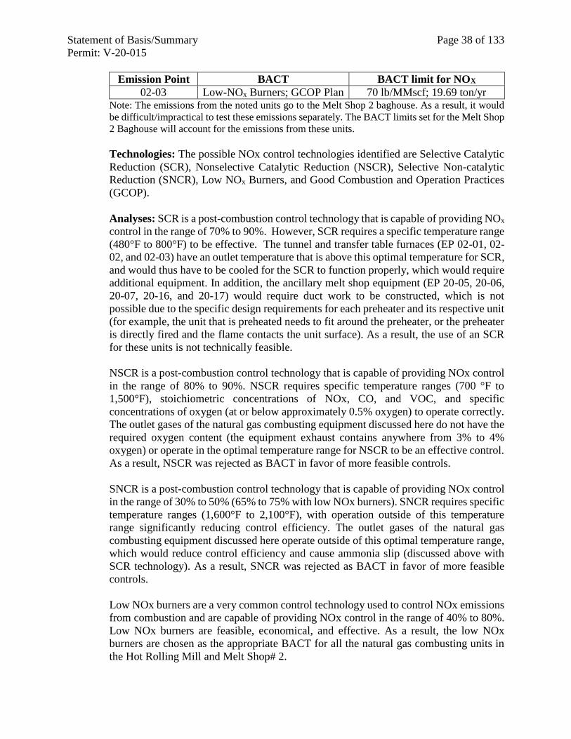
Statement of Basis/Summary Page 38 of 133
Permit: V-20-015
Emission Point BACT BACT limit for NOX
02-03 Low-NOx Burners; GCOP Plan 70 lb/MMscf; 19.69 ton/yr Note: The emissions from the noted units go to the Melt Shop 2 baghouse. As a result, it would
be difficult/impractical to test these emissions separately. The BACT limits set for the Melt Shop
2 Baghouse will account for the emissions from these units.
Technologies: The possible NOx control technologies identified are Selective Catalytic
Reduction (SCR), Nonselective Catalytic Reduction (NSCR), Selective Non-catalytic
Reduction (SNCR), Low NOx Burners, and Good Combustion and Operation Practices
(GCOP).
Analyses: SCR is a post-combustion control technology that is capable of providing NOx
control in the range of 70% to 90%. However, SCR requires a specific temperature range
(480°F to 800°F) to be effective. The tunnel and transfer table furnaces (EP 02-01, 02-
02, and 02-03) have an outlet temperature that is above this optimal temperature for SCR,
and would thus have to be cooled for the SCR to function properly, which would require
additional equipment. In addition, the ancillary melt shop equipment (EP 20-05, 20-06,
20-07, 20-16, and 20-17) would require duct work to be constructed, which is not
possible due to the specific design requirements for each preheater and its respective unit
(for example, the unit that is preheated needs to fit around the preheater, or the preheater
is directly fired and the flame contacts the unit surface). As a result, the use of an SCR
for these units is not technically feasible.
NSCR is a post-combustion control technology that is capable of providing NOx control
in the range of 80% to 90%. NSCR requires specific temperature ranges (700 °F to
1,500°F), stoichiometric concentrations of NOx, CO, and VOC, and specific
concentrations of oxygen (at or below approximately 0.5% oxygen) to operate correctly.
The outlet gases of the natural gas combusting equipment discussed here do not have the
required oxygen content (the equipment exhaust contains anywhere from 3% to 4%
oxygen) or operate in the optimal temperature range for NSCR to be an effective control.
As a result, NSCR was rejected as BACT in favor of more feasible controls.
SNCR is a post-combustion control technology that is capable of providing NOx control
in the range of 30% to 50% (65% to 75% with low NOx burners). SNCR requires specific
temperature ranges (1,600°F to 2,100°F), with operation outside of this temperature
range significantly reducing control efficiency. The outlet gases of the natural gas
combusting equipment discussed here operate outside of this optimal temperature range,
which would reduce control efficiency and cause ammonia slip (discussed above with
SCR technology). As a result, SNCR was rejected as BACT in favor of more feasible
controls.
Low NOx burners are a very common control technology used to control NOx emissions
from combustion and are capable of providing NOx control in the range of 40% to 80%.
Low NOx burners are feasible, economical, and effective. As a result, the low NOx
burners are chosen as the appropriate BACT for all the natural gas combusting units in
the Hot Rolling Mill and Melt Shop# 2.
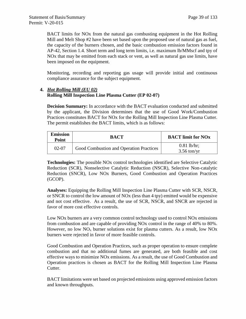
Statement of Basis/Summary Page 39 of 133
Permit: V-20-015
BACT limits for NOx from the natural gas combusting equipment in the Hot Rolling
Mill and Melt Shop #2 have been set based upon the proposed use of natural gas as fuel,
the capacity of the burners chosen, and the basic combustion emission factors found in
AP-42, Section 1.4. Short term and long term limits, i.e. maximum lb/MMscf and tpy of
NOx that may be emitted from each stack or vent, as well as natural gas use limits, have
been imposed on the equipment.
Monitoring, recording and reporting gas usage will provide initial and continuous
compliance assurance for the subject equipment.
4. Hot Rolling Mill (EU 02)
Rolling Mill Inspection Line Plasma Cutter (EP 02-07)
Decision Summary: In accordance with the BACT evaluation conducted and submitted
by the applicant, the Division determines that the use of Good Work/Combustion
Practices constitutes BACT for NOx for the Rolling Mill Inspection Line Plasma Cutter.
The permit establishes the BACT limits, which is as follows:
Emission
Point BACT BACT limit for NOx
02-07 Good Combustion and Operation Practices 0.81 lb/hr;
3.56 ton/yr
Technologies: The possible NOx control technologies identified are Selective Catalytic
Reduction (SCR), Nonselective Catalytic Reduction (NSCR), Selective Non-catalytic
Reduction (SNCR), Low NOx Burners, Good Combustion and Operation Practices
(GCOP).
Analyses: Equipping the Rolling Mill Inspection Line Plasma Cutter with SCR, NSCR,
or SNCR to control the low amount of NOx (less than 4 tpy) emitted would be expensive
and not cost effective. As a result, the use of SCR, NSCR, and SNCR are rejected in
favor of more cost effective controls.
Low NOx burners are a very common control technology used to control NOx emissions
from combustion and are capable of providing NOx control in the range of 40% to 80%.
However, no low NOx burner solutions exist for plasma cutters. As a result, low NOx
burners were rejected in favor of more feasible controls.
Good Combustion and Operation Practices, such as proper operation to ensure complete
combustion and that no additional fumes are generated, are both feasible and cost
effective ways to minimize NOx emissions. As a result, the use of Good Combustion and
Operation practices is chosen as BACT for the Rolling Mill Inspection Line Plasma
Cutter.
BACT limitations were set based on projected emissions using approved emission factors
and known throughputs.
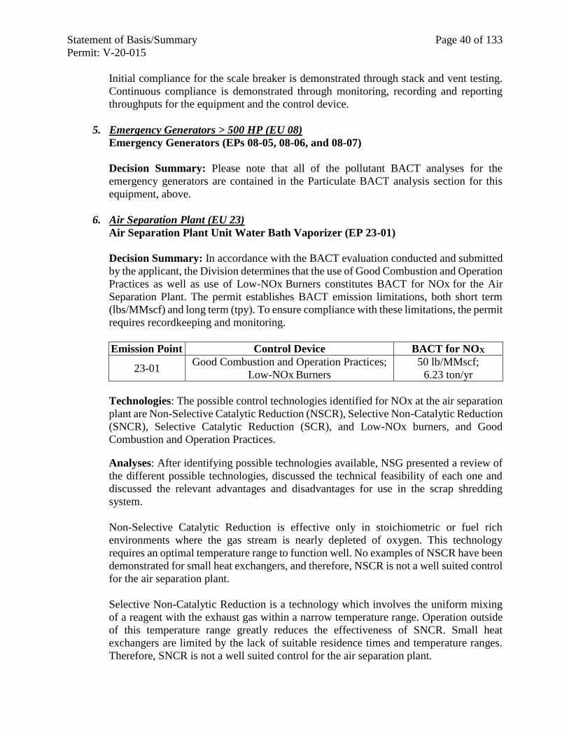
Statement of Basis/Summary Page 40 of 133
Permit: V-20-015
Initial compliance for the scale breaker is demonstrated through stack and vent testing.
Continuous compliance is demonstrated through monitoring, recording and reporting
throughputs for the equipment and the control device.
5. Emergency Generators > 500 HP (EU 08)
Emergency Generators (EPs 08-05, 08-06, and 08-07)
Decision Summary: Please note that all of the pollutant BACT analyses for the
emergency generators are contained in the Particulate BACT analysis section for this
equipment, above.
6. Air Separation Plant (EU 23)
Air Separation Plant Unit Water Bath Vaporizer (EP 23-01)
Decision Summary: In accordance with the BACT evaluation conducted and submitted
by the applicant, the Division determines that the use of Good Combustion and Operation
Practices as well as use of Low-NOx Burners constitutes BACT for NOx for the Air
Separation Plant. The permit establishes BACT emission limitations, both short term
(lbs/MMscf) and long term (tpy). To ensure compliance with these limitations, the permit
requires recordkeeping and monitoring.
Emission Point Control Device BACT for NOX
23-01 Good Combustion and Operation Practices;
Low-NOx Burners
50 lb/MMscf;
6.23 ton/yr
Technologies: The possible control technologies identified for NOx at the air separation
plant are Non-Selective Catalytic Reduction (NSCR), Selective Non-Catalytic Reduction
(SNCR), Selective Catalytic Reduction (SCR), and Low-NOx burners, and Good
Combustion and Operation Practices.
Analyses: After identifying possible technologies available, NSG presented a review of
the different possible technologies, discussed the technical feasibility of each one and
discussed the relevant advantages and disadvantages for use in the scrap shredding
system.
Non-Selective Catalytic Reduction is effective only in stoichiometric or fuel rich
environments where the gas stream is nearly depleted of oxygen. This technology
requires an optimal temperature range to function well. No examples of NSCR have been
demonstrated for small heat exchangers, and therefore, NSCR is not a well suited control
for the air separation plant.
Selective Non-Catalytic Reduction is a technology which involves the uniform mixing
of a reagent with the exhaust gas within a narrow temperature range. Operation outside
of this temperature range greatly reduces the effectiveness of SNCR. Small heat
exchangers are limited by the lack of suitable residence times and temperature ranges.
Therefore, SNCR is not a well suited control for the air separation plant.
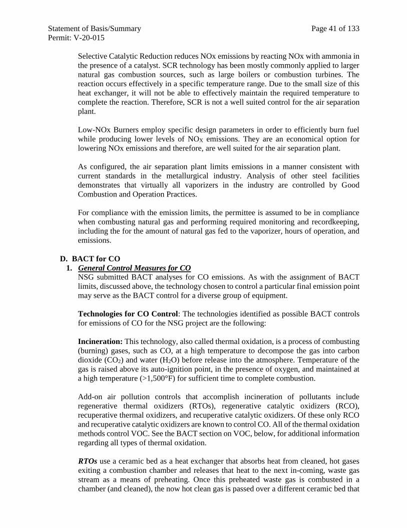
Statement of Basis/Summary Page 41 of 133
Permit: V-20-015
Selective Catalytic Reduction reduces NOx emissions by reacting NOx with ammonia in
the presence of a catalyst. SCR technology has been mostly commonly applied to larger
natural gas combustion sources, such as large boilers or combustion turbines. The
reaction occurs effectively in a specific temperature range. Due to the small size of this
heat exchanger, it will not be able to effectively maintain the required temperature to
complete the reaction. Therefore, SCR is not a well suited control for the air separation
plant.
Low-NOx Burners employ specific design parameters in order to efficiently burn fuel
while producing lower levels of NOX emissions. They are an economical option for
lowering NOx emissions and therefore, are well suited for the air separation plant.
As configured, the air separation plant limits emissions in a manner consistent with
current standards in the metallurgical industry. Analysis of other steel facilities
demonstrates that virtually all vaporizers in the industry are controlled by Good
Combustion and Operation Practices.
For compliance with the emission limits, the permittee is assumed to be in compliance
when combusting natural gas and performing required monitoring and recordkeeping,
including the for the amount of natural gas fed to the vaporizer, hours of operation, and
emissions.
D. BACT for CO
1. General Control Measures for CO
NSG submitted BACT analyses for CO emissions. As with the assignment of BACT
limits, discussed above, the technology chosen to control a particular final emission point
may serve as the BACT control for a diverse group of equipment.
Technologies for CO Control: The technologies identified as possible BACT controls
for emissions of CO for the NSG project are the following:
Incineration: This technology, also called thermal oxidation, is a process of combusting
(burning) gases, such as CO, at a high temperature to decompose the gas into carbon
dioxide (CO2) and water (H2O) before release into the atmosphere. Temperature of the
gas is raised above its auto-ignition point, in the presence of oxygen, and maintained at
a high temperature (>1,500°F) for sufficient time to complete combustion.
Add-on air pollution controls that accomplish incineration of pollutants include
regenerative thermal oxidizers (RTOs), regenerative catalytic oxidizers (RCO),
recuperative thermal oxidizers, and recuperative catalytic oxidizers. Of these only RCO
and recuperative catalytic oxidizers are known to control CO. All of the thermal oxidation
methods control VOC. See the BACT section on VOC, below, for additional information
regarding all types of thermal oxidation.
RTOs use a ceramic bed as a heat exchanger that absorbs heat from cleaned, hot gases
exiting a combustion chamber and releases that heat to the next in-coming, waste gas
stream as a means of preheating. Once this preheated waste gas is combusted in a
chamber (and cleaned), the now hot clean gas is passed over a different ceramic bed that
Statement of Basis/Summary Page 42 of 133
Permit: V-20-015
was cooled in the previous cycle. This now heated bed begins the next cycle by
preheating the next in-coming waste gas stream. RTOs are the most common means of
VOC control, have high temperature capability, are fairly rugged and easy to maintain
and produce less NOx emissions than flares. Disadvantages include high capital costs,
large size with complex, expensive installation, and high maintenance demand for
moving parts.
RCOs operate in the same type of cycle as an RTO, but use a catalyst material rather than
ceramic for the bed. A catalyst is a substance that increases the rate of a chemical reaction
without undergoing permanent chemical change itself. Since the material in the bed
pushes the combustion of the waste gases, it allows for the cleaning process to occur at a
lower temperature. This means a less fuel required to complete combustion in the
combustion chamber. RCOs have lower fuel requirements and less NOx emissions than
RTOs. However, the need to change out the catalyst, usually platinum, palladium or
rhodium, translates to higher long-term maintenance costs. RCOs also have high capital
costs and require a large area.
Recuperative thermal oxidizers are similar to RTOs in that they use incineration to
destroy pollutants in waste gas, but the regenerative passes hot exhaust gas and cooler
inlet gas through (or over) one or more fixed heat exchanger beds while the recuperative
passes hot exhaust through an air-to air heat exchanger to heat the cooler inlet gas.
Recuperative thermal oxidizers use metallic shell and tube heat exchangers to accomplish
the transfer. They are good for low volume applications, are compact and have a long life
span. Disadvantages include the higher energy costs (operating costs) and are not
effective for higher air flows (>30,000 cfm).
Recuperative catalytic oxidizers are arranged such that after in-coming waste gases are
heated in the heat exchanger, they passed through a catalyst to enhance the oxidation
process in the combustion chamber. As with the RCO, full combustion can occur at lower
temperatures than in the non-catalytic recuperative thermal oxidizer. This means
recuperative catalytic oxidizers have lower fuel costs and produce fewer NOx emissions.
Some disadvantages of this form of control are the high capital costs and higher long
term maintenance costs.
Flare: This is a high-temperature, open combustion process wherein combustible
components, mostly hydrocarbons, of waste gases from industrial operations are burned
off. There are two types of flares, elevated and ground flares. Elevated flares are more
common and consist of a waste gas stream combusted at the tip of a stack that may be
from 10 to 100 meters tall. They are open to the elements and can be affected by wind
and precipitation. For ground flares, the combustion takes place at ground level. Flares
can also be classified by the type of mixing that occurs at the flare tip, i.e., steam-assisted,
air-assisted, pressure assisted, or non-assisted. Per the EPA Air Pollution Control
Technology Fact Sheet for flares, these devices are primarily safety mechanisms meant
to deal with short term conditions rather than for continuous waste streams. They can be
economical to dispose of sudden releases of large amounts of gas, do not usually require
extra fuel and can control intermittent waste streams. Disadvantages include smoke and
noise, heat released is wasted and they can actually create additional pollution, including
SOx, NOx, and CO.
Statement of Basis/Summary Page 43 of 133
Permit: V-20-015
Good Combustion and Operation Practices: This is a combustion optimization work
practices method for minimizing fuel use and emissions from the burning of fossil fuels.
Oxygen and carbon in the fuel combine during combustion in a complex process
requiring turbulence, temperature and time for the reactants to contact and combine to
form carbon dioxide (CO2) and heat. If the combustion and combination of necessary
elements are not controlled, the combustion of the fuel is incomplete and undesirable
emissions form. Particulates from natural gas combustion are usually larger molecular
weight hydrocarbons that are not fully combusted. Increased PM emissions may result
from poor air/fuel mixing or maintenance problems. CO also occurs when there is poor
mixing (not enough turbulence) and/or there is not enough air in the mix. Other pollutants
such as NOx form if the temperature is too hot. SO2 can form if there is too much sulfur
in the fuel. By taking measures to optimize the combustion process, pollutants are
minimized. These measures may include choosing good burner designs, using
performance monitoring and process control techniques to improve operation,
performing regular and thorough maintenance of the combustion system, etc. Although
it is not an add-on control, efficient operation of combustion equipment is often an
effective means to reduce combustion related pollutants. Preparation of a specific plan
for achieving combustion optimization, such as a Good Combustion and Operation
Practices (GCOP) Plan, that defines, measures and verifies the use of operational and
design practices specific to a piece of equipment for the reduction of a specific pollutant
provides verifiable implementation of this work practices method.
Clean Fuel Use: This is a practice whereby a facility or specific equipment is designed
to use cleaner fuels (such as natural gas, liquid petroleum gas or blends), that emit
pollutants in lesser quantities than the alternatives (such as fuel oils or coal).
Scrap Management: By inspecting scrap or contracting to receive scrap with specific
requirements, feed materials with fewer oils and lubricants can be selected for processing.
This directly reduces CO and VOC emissions. Rejecting painted and coated scrap also
reduces CO and VOCs as well as some HAPs and Toxics.
Note that for the much of the melt shop and casting equipment, CO and VOC analyses
are included in this section together since controls for these two criteria pollutants are the
same or complimentary in controlling the emissions. Equipment that does not emit CO,
but does emit VOCs, is discussed separately in the BACT Analysis for VOCs, below.
See that section for the list of possible VOC controls.
2. Melt Shop #2 (EU 20) & Melt Shop #1 (EU 01)
Single Shell DC Electric Arc Furnace (EP 20-01), Ladle Metallurgy Furnaces A&B
(EP 20-02A & B), Continuous Caster B-Line (EP 20-03), Twin-Shell DC Electric
Arc Furnaces (EP 01-01), Ladle Metallurgy Furnaces A&B (EP 01-03A & B),
Continuous Caster A-Line (EP 01-02)
These units are unchanged in the revised project application, however, the issue of
demonstrating compliance with lb/ton emission limitations continuously using the
CEMS, including during periods of non-production, was raised. Accordingly, to provide
for periods of non-production, separate emission limitations have been established based
on operation of only the natural gas combustion units during periods of EAF (and
Statement of Basis/Summary Page 44 of 133
Permit: V-20-015
downstream equipment) non-operation. The limit is based on all combustion processes
in both melt shops, as these combustion emissions can travel freely within the building,
and cannot therefore be attributed to any one specific stack. These time periods are
defined within the permit. Emissions during these downtimes will continue to be counted
toward the long-term ton/year emission limit. This change was only made to emission
limitations for which CEMS are used to demonstrate continuous compliance.
Emission Point BACT BACT limit for CO
Baghouse #1 & #2
Stack
Natural Gas-fired oxy-fuel
burners; GCOP Plan
Production Days:
2.0 lb/ton 2,000
ton/yr Non-Production Days:
42.6 lb/hr
Baghouse #3 Stack Natural Gas-fired oxy-fuel
burners; GCOP Plan
Production Days:
2.0 lb/ton 2,000
ton/yr Non-Production Days:
42.6 lb/hr
Note: BACT lb/ton and lb/hr limits for production days are based on 30-day rolling
averages. BACT lb/hr limits for non-production days is based on a 24 hour average.
BACT ton/yr limit is based on a 12-month rolling average.
3. Melt Shop #2 (EU 20) & Hot Rolling Mill (EU 02): Combustion Units
Three Horizontal Ladle Preheaters (EP 20-05A, B, & C), Two Tundish Preheaters
(EP 20-06A & B), One Mandrel Preheater and two Tundish Submerged Entry
Nozzle (SEN) preheaters (EP 20 07A, B, & C), Melt Shop #2 Safety Lining Dryer
for Tundishes (EP 20-16), Melt Shop #2 Vertical Ladle Pre-Heater at LMF (EP 20-
17), A-Line Tunnel Furnace (EP 02-01), B-Line Tunnel Furnace (EP 02-02), &
Heated Transfer Table Furnace (EP 02-03)
Decision Summary: In accordance with the BACT evaluation conducted and submitted
by the applicant, the Division determines that the development of a Good Combustion
and Operation Practices (GCOP) Plan constitutes BACT for CO for the following natural
gas combusting units in Melt Shop #2 (EU 20) and Hot Rolling Mill (EU 02). The permit
establishes the BACT limits, both short term (lb/MMscf) and long term (ton/year), which
are as follows:
Emission Point BACT BACT limit for CO
20-05A, B, & C GCOP Plan See Note
20-06A & B GCOP Plan See Note
20-07A, B, & C GCOP Plan See Note
20-16 GCOP Plan See Note
20-17 GCOP Plan See Note
02-01 GCOP Plan 84 lb/MMscf; 37.62 ton/yr
02-02 GCOP Plan 84 lb/MMscf; 58.83 ton/yr
02-03 GCOP Plan 84 lb/MMscf; 23.63 ton/yr Note: The emissions from the noted units go to the Melt Shop 2 baghouse. As a result, it would
be difficult/impractical to test these emissions separately. The BACT limits set for the Melt Shop
2 Baghouse will account for the emissions from these units.
Statement of Basis/Summary Page 45 of 133
Permit: V-20-015
Technologies: The possible CO control technologies identified for the melt shop are
certain types of Incineration (oxidation), Flares, and Good Combustion and Operation
Practices (GCOP).
Analyses: After identifying possible CO control technologies, the technical feasibility
and some relative control efficiencies of the technologies were examined.
Although catalytic types of thermal oxidizers are technically feasible, that is they could
be installed and would remove some CO, they would not be cost efficient for removing
the amount of CO emitted by the natural-gas burners of the Hot Rolling Mill and Melt
Shop #2. According to the EPA Air Pollution Control Technology Fact Sheet for
regenerative incinerators, RTOs do not remove CO, but an RCO system, using precious
metal-based catalyst, can remove 98 % of the CO in a “VOC laden” air stream. The
additional removal of VOC emissions from the natural gas combusting units, which
themselves emit a small amount of VOC, would not be enough to justify the high capital
costs and long term maintenance costs of use of this control for CO removal.
Good Combustion and Operation Practices for combustion optimization is technically
feasible for any combustion process. In the case of minimizing the formation of CO in
the melt shop, developing a plan to ensure full combustion of the natural gas would
provide the best means for limiting this pollutant.
With BACT established as combustion optimization, the permit requires that NSG must
prepare a GCOP plan within 90 days of equipment startup. The permittee must define,
measure, and verify the use of operational and design practices determined as CO BACT.
The permittee is also required to operate as outlined in the plan, verify the optimization
practices are occurring, and confirm that the facility is lowering its energy consumption.
BACT limits for CO from the natural gas combusting equipment in the Hot Rolling Mill
and Melt Shop #2 have been set based upon the proposed use of natural gas as fuel, the
capacity of the burners chosen, and the basic combustion emission factors found in AP-
42, Section 1.4. Short term and long term limits, i.e. maximum lb/MMscf and tpy of CO
that may be emitted from each stack or vent, as well as natural gas use limits, have been
imposed on the equipment of the melt shop.
Initial compliance demonstration with BACT will be through development of a GCOP
plan within 90 days of equipment startup. Implementation of the GCOP plan and
monitoring, recording and reporting gas usage will provide continuous compliance
assurance for the subject equipment.
4. Emergency Generators > 500 HP (EU 08)
Emergency Generators (EPs 08-05, 08-06, and 08-07)
Decision Summary: Please note that all of the pollutant BACT analyses for the
emergency generators are contained in the Particulate BACT analysis section for this
equipment, above.
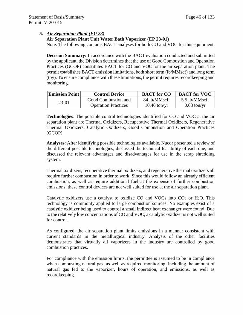
Statement of Basis/Summary Page 46 of 133
Permit: V-20-015
5. Air Separation Plant (EU 23)
Air Separation Plant Unit Water Bath Vaporizer (EP 23-01)
Note: The following contains BACT analyses for both CO and VOC for this equipment.
Decision Summary: In accordance with the BACT evaluation conducted and submitted
by the applicant, the Division determines that the use of Good Combustion and Operation
Practices (GCOP) constitutes BACT for CO and VOC for the air separation plant. The
permit establishes BACT emission limitations, both short term (lb/MMscf) and long term
(tpy). To ensure compliance with these limitations, the permit requires recordkeeping and
monitoring.
Emission Point Control Device BACT for CO BACT for VOC
23-01 Good Combustion and
Operation Practices
84 lb/MMscf;
10.46 ton/yr
5.5 lb/MMscf;
0.68 ton/yr
Technologies: The possible control technologies identified for CO and VOC at the air
separation plant are Thermal Oxidizers, Recuperative Thermal Oxidizers, Regenerative
Thermal Oxidizers, Catalytic Oxidizers, Good Combustion and Operation Practices
(GCOP).
Analyses: After identifying possible technologies available, Nucor presented a review of
the different possible technologies, discussed the technical feasibility of each one, and
discussed the relevant advantages and disadvantages for use in the scrap shredding
system.
Thermal oxidizers, recuperative thermal oxidizers, and regenerative thermal oxidizers all
require further combustion in order to work. Since this would follow an already efficient
combustion, as well as require additional fuel at the expense of further combustion
emissions, these control devices are not well suited for use at the air separation plant.
Catalytic oxidizers use a catalyst to oxidize CO and VOCs into CO2 or H2O. This
technology is commonly applied to large combustion sources. No examples exist of a
catalytic oxidizer being used to control a small indirect heat exchanger were found. Due
to the relatively low concentrations of CO and VOC, a catalytic oxidizer is not well suited
for control.
As configured, the air separation plant limits emissions in a manner consistent with
current standards in the metallurgical industry. Analysis of the other facilities
demonstrates that virtually all vaporizers in the industry are controlled by good
combustion practices.
For compliance with the emission limits, the permittee is assumed to be in compliance
when combusting natural gas, as well as required monitoring, including the amount of
natural gas fed to the vaporizer, hours of operation, and emissions, as well as
recordkeeping.
Statement of Basis/Summary Page 47 of 133
Permit: V-20-015
E. BACT for VOC
1. General Control Measures for VOC
NSG submitted a BACT analysis for VOC. Several VOC technologies were identified
and discussed. As with PM/PM10/PM2.5 and other pollutants, the technologies were
evaluated in light of the groups of equipment likely to be served by a single control
device. As with the assignment of BACT limits, discussed above, the technology chosen
to control a particular final emission point may serve as the BACT control for a diverse
group of equipment.
Technologies for VOC Control: The technologies identified as possible BACT controls
for emissions of VOC for the NSG project are the following:
Incineration: As discussed under CO control technologies, incineration (thermal
oxidation) is a process of burning gases, such as VOCs, at a high temperature to reduce
the gas into CO2 and water. Temperature of the gas is raised in the presence of oxygen
and maintained at a high temperature to complete combustion. Per the U.S. EPA Air
Pollution Control Technology Fact Sheet for Thermal Incinerator, destruction of VOC
efficiencies range from 98 to 99.99% effective for this type of control. Design parameters
such as chamber temperature, residence time, inlet VOC loading, compounds, and
mixing affect the final destruction efficiency. Thermal incinerators are not well suited to
highly variable flow waste gas streams.
Add-on air pollution controls that accomplish incineration of pollutants include
regenerative thermal oxidizers (RTOs), regenerative catalytic oxidizers (RCO),
recuperative thermal oxidizers, and recuperative catalytic oxidizers. All of these controls
are known to reduce VOC in waste gas streams.
RTOs, as discussed under CO BACT, use a ceramic bed heat exchanger to preheat
incoming waste gas for combustion and cool (absorb heat from) the exiting cleaned gas.
These controls are mostly used for VOC control. RTOs have VOC destructive efficiency
that ranges from 95 to 99 % with the lower efficiencies generally being associated with
lower VOC concentrations in the waste gas flow.
RCOs, as discussed under CO BACT, operate in a manner similar to that of an RTO, but
use a catalyst material to drive the combustion of the waste gases at a lower temperature.
RCOs typically have efficiencies in the 90 to 99 % effective range for VOC, but have an
additional advantage in that they also destroy 98 % and more of the CO in a waste gas
stream, too.
Recuperative thermal oxidizers, as discussed under CO BACT, are similar to an RTO,
but use an air to air heat exchanger rather than a ceramic bed. Depending on
characteristics of the waste stream, efficiencies range from 98 % to 99.9999+ %
destruction of VOCs. Waste streams generally require 1500 to 3000 ppmv of VOC to
achieve higher efficiencies.
Recuperative catalytic oxidizers, as discussed under CO BACT, are much like RCOs.
This device uses a catalyst to enhance combustion so that gas cleaning (burning) can
occur at lower temperatures. This means recuperative catalytic oxidizers have lower
Statement of Basis/Summary Page 48 of 133
Permit: V-20-015
operating costs, and produce fewer NOx emissions. Disadvantages of this type of control
are high capital, high long term maintenance costs, and expensive catalysts.
Flare: As discussed under CO BACT, flaring is a high-temperature, open combustion
process where components of industrial waste gases are burned off. They are often gas
streams combusted at the tip of a stack but may also be at ground level. Open to weather,
they are affected by wind and precipitation. There are several forms of flares based on
the type of mixing that occurs, and are considered primarily safety mechanisms meant to
deal with short term conditions rather than for continuous waste streams.
Scrubbers: These controls, previously discussed for the removal of particulate, can also
be used for the removal of other pollutants, such as VOCs. For the removal of organics,
a liquid solvent is sprayed through an organics containing gas stream. Contact between
the absorbing liquid (solvent) and the vent gas can occur in a number of different
configurations (counter current spray tower, scrubber, or packed or plate columns). For
wet scrubbers, the process gas stream is either sprayed with a liquid or forced into contact
with a liquid in order to impact and remove particles entrained in the gas. The liquid
droplets, containing the captured organic, are collected from the gas stream in a mist
eliminator. The resulting liquid must then be treated. Dry scrubbers, that use alkaline
slurries or sorbents, are generally used for the removal of acid gases and their precursors
such as sulfur oxides (SO2 and SO3) and Hydrogen Chloride (HCl).
Carbon Adsorption: This is a process by which gas molecules are passed through a bed
of solid carbon particles and are held on the surface of the solids by attractive forces.
Adsorption is a surface-based process and in this form, activated carbon, that has a high
number of tiny low-volume pores (i.e., it is microporous), is used as the adsorbent. The
adsorbed gas molecules can be removed from the adsorbent by heat or vacuum when the
adsorbent is regenerated. Activated carbon is commonly used to remove VOCs from a
gas stream.
Membranes: This is another type of adsorption technology used for the selective
separation of gases in a waste stream. In this technology, specially developed permeable
materials allow different components in a gas stream pass through at different rates or
selectively allow only certain molecules to pass through. Diffusion across a membrane
can happen under different mechanisms. Molecular sieving occurs when pores are too
small and specifically shaped to allow one component to pass through. These membranes
are often synthetic polymers of intrinsic microporosity, that is the openings are tiny and
just a few billionths of a meter in size. Another type of diffusion is low pressure driven
where lighter particles travel across the membrane faster than other particles and can be
captured. There is also solution-diffusion where particles in the waste gas are dissolved
onto the membrane and then diffuse through the membrane at different component-
specific rates.
Absorption: This is a process whereby certain components in a gas stream (such as
VOCs) are removed by dissolving them into a liquid. The gas may be simply dissolved
within the liquid (straight dissolution) or irreversibly reacted with a chemical liquid
absorbent (dissolution with chemical reaction). This process differs from adsorption in
that in adsorption, the pollutant collects on a solid surface. In absorption the pollutant
passes into the liquid and is distributed throughout the liquid phase. Absorption is often
Statement of Basis/Summary Page 49 of 133
Permit: V-20-015
used in the control of acid gases such as sulfuric acid gas (H2SO4), hydrochloric acid gas
(HCl), and nitric acid gas (HNO3).
Condensation: This is a technique where the temperature of a waste gas stream is
lowered at constant pressure or pressure is increased at a constant temperature to force
VOC(s) to change from the gas or vapor state to a liquid state. The VOC(s) in liquid form
is then collected. Condensers are mostly used when there are only one or two VOCs in
the waste gas stream. There are two general types of condensers: Conventional systems
that use chilled water; and refrigeration/cryogenic units that use chemical refrigerants,
even liquid nitrogen, to achieve extremely low temperatures. Condensation is often used
when recovered VOCs have high economic value. They can also be used to concentrate
the VOC stream before sending it to a second control device such as an RTO for thermal
destruction.
Volume Concentration: This technique is used for control of low-concentration VOC
or HAP gas streams. The goal of concentration is to gather as much of a pollutant as
possible before treating the target compound extracted from the waste stream.
Concentrators are often designed in a rotary carousel system. Each sector of the carousel
alternately adsorbs VOC and/or HAP and then releases it as the section is regenerated by
being subjected to hot gas. The higher concentration gas can then be treated via another
control such as thermal oxidation or fixed-bed adsorption.
Biodegradation: In air pollution control, biodegradation is the process of removing
contaminants from waste gas streams through using the natural ability of some
microorganisms (bioreactors) to degrade, transform or accumulate those contaminants.
Different air-type bioreactors used for odor and VOC removal include biofilters,
biotrickling filters, and bioscrubbers. Some highly soluble and low molecular weight
VOCs, such as methanol and aldehydes, are easily digested in bioreactors.
Ultra Violet (UV) Oxidation: This control technique uses oxygen-based chemicals to
convert VOCs into CO2 and H2O in the presence of specific frequency UV light. The UV
radiation excites the oxygen-based chemicals (often ozone and/or peroxide) to destroy
the VOCs.
Good Combustion and Operation Practices: As discussed previously, this is a work
practices combustion optimization method for minimizing fuel use and emissions from
the fossil fuels. If the combustion and combination of necessary elements are not
controlled, the combustion of the fuel is incomplete and undesirable emissions, such as
VOCs, form. By taking measures to optimize the combustion process, pollutants are
minimized. Preparation of a specific plan for achieving combustion optimization, such
as a Good Combustion and Operation Practices (GCOP) Plan, that defines, measures,
and verifies the use of operational and design practices specific to a piece of equipment
for the reduction of a specific pollutant provides verifiable implementation of this work
practices method. Although it is not an add-on control, efficient operation of combustion
equipment is often an effective means to reduce VOCs and other combustion related
pollutants.
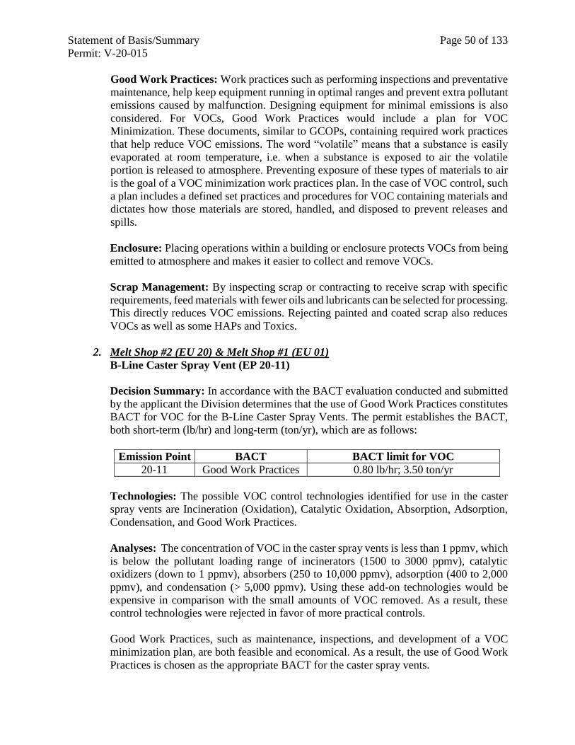
Statement of Basis/Summary Page 50 of 133
Permit: V-20-015
Good Work Practices: Work practices such as performing inspections and preventative
maintenance, help keep equipment running in optimal ranges and prevent extra pollutant
emissions caused by malfunction. Designing equipment for minimal emissions is also
considered. For VOCs, Good Work Practices would include a plan for VOC
Minimization. These documents, similar to GCOPs, containing required work practices
that help reduce VOC emissions. The word “volatile” means that a substance is easily
evaporated at room temperature, i.e. when a substance is exposed to air the volatile
portion is released to atmosphere. Preventing exposure of these types of materials to air
is the goal of a VOC minimization work practices plan. In the case of VOC control, such
a plan includes a defined set practices and procedures for VOC containing materials and
dictates how those materials are stored, handled, and disposed to prevent releases and
spills.
Enclosure: Placing operations within a building or enclosure protects VOCs from being
emitted to atmosphere and makes it easier to collect and remove VOCs.
Scrap Management: By inspecting scrap or contracting to receive scrap with specific
requirements, feed materials with fewer oils and lubricants can be selected for processing.
This directly reduces VOC emissions. Rejecting painted and coated scrap also reduces
VOCs as well as some HAPs and Toxics.
2. Melt Shop #2 (EU 20) & Melt Shop #1 (EU 01)
B-Line Caster Spray Vent (EP 20-11)
Decision Summary: In accordance with the BACT evaluation conducted and submitted
by the applicant the Division determines that the use of Good Work Practices constitutes
BACT for VOC for the B-Line Caster Spray Vents. The permit establishes the BACT,
both short-term (lb/hr) and long-term (ton/yr), which are as follows:
Emission Point BACT BACT limit for VOC
20-11 Good Work Practices 0.80 lb/hr; 3.50 ton/yr
Technologies: The possible VOC control technologies identified for use in the caster
spray vents are Incineration (Oxidation), Catalytic Oxidation, Absorption, Adsorption,
Condensation, and Good Work Practices.
Analyses: The concentration of VOC in the caster spray vents is less than 1 ppmv, which
is below the pollutant loading range of incinerators (1500 to 3000 ppmv), catalytic
oxidizers (down to 1 ppmv), absorbers (250 to 10,000 ppmv), adsorption (400 to 2,000
ppmv), and condensation (> 5,000 ppmv). Using these add-on technologies would be
expensive in comparison with the small amounts of VOC removed. As a result, these
control technologies were rejected in favor of more practical controls.
Good Work Practices, such as maintenance, inspections, and development of a VOC
minimization plan, are both feasible and economical. As a result, the use of Good Work
Practices is chosen as the appropriate BACT for the caster spray vents.
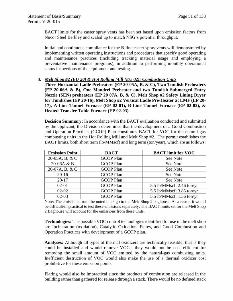
Statement of Basis/Summary Page 51 of 133
Permit: V-20-015
BACT limits for the caster spray vents has been set based upon emission factors from
Nucor Steel Berkley and scaled up to match NSG’s potential throughput.
Initial and continuous compliance for the B-line caster spray vents will demonstrated by
implementing written operating instructions and procedures that specify good operating
and maintenance practices (including tracking material usage and employing a
preventative maintenance programs), in addition to performing monthly operational
status inspections of the equipment and testing.
3. Melt Shop #2 (EU 20) & Hot Rolling Mill (EU 02): Combustion Units
Three Horizontal Ladle Preheaters (EP 20-05A, B, & C), Two Tundish Preheaters
(EP 20-06A & B), One Mandrel Preheater and two Tundish Submerged Entry
Nozzle (SEN) preheaters (EP 20 07A, B, & C), Melt Shop #2 Safety Lining Dryer
for Tundishes (EP 20-16), Melt Shop #2 Vertical Ladle Pre-Heater at LMF (EP 20-
17), A-Line Tunnel Furnace (EP 02-01), B-Line Tunnel Furnace (EP 02-02), &
Heated Transfer Table Furnace (EP 02-03)
Decision Summary: In accordance with the BACT evaluation conducted and submitted
by the applicant, the Division determines that the development of a Good Combustion
and Operation Practices (GCOP) Plan constitutes BACT for VOC for the natural gas
combusting units in the Hot Rolling Mill and Melt Shop #2. The permit establishes the
BACT limits, both short term (lb/MMscf) and long term (ton/year), which are as follows:
Emission Point BACT BACT limit for VOC
20-05A, B, & C GCOP Plan See Note
20-06A & B GCOP Plan See Note
20-07A, B, & C GCOP Plan See Note
20-16 GCOP Plan See Note
20-17 GCOP Plan See Note
02-01 GCOP Plan 5.5 lb/MMscf; 2.46 ton/yr
02-02 GCOP Plan 5.5 lb/MMscf; 3.85 ton/yr
02-03 GCOP Plan 5.5 lb/MMscf; 1.56 ton/yr Note: The emissions from the noted units go to the Melt Shop 2 baghouse. As a result, it would
be difficult/impractical to test these emissions separately. The BACT limits set for the Melt Shop
2 Baghouse will account for the emissions from these units.
Technologies: The possible VOC control technologies identified for use in the melt shop
are Incineration (oxidation), Catalytic Oxidation, Flares, and Good Combustion and
Operation Practices with development of a GCOP plan.
Analyses: Although all types of thermal oxidizers are technically feasible, that is they
could be installed and would remove VOCs, they would not be cost efficient for
removing the small amount of VOC emitted by the natural-gas combusting units.
Inefficient destruction of VOC would also make the use of a thermal oxidizer cost
prohibitive for these emission points.
Flaring would also be impractical since the products of combustion are released in the
building rather than gathered for release through a stack. There would be no defined stack
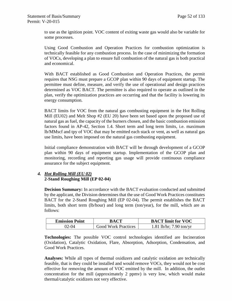
Statement of Basis/Summary Page 52 of 133
Permit: V-20-015
to use as the ignition point. VOC content of exiting waste gas would also be variable for
some processes.
Using Good Combustion and Operation Practices for combustion optimization is
technically feasible for any combustion process. In the case of minimizing the formation
of VOCs, developing a plan to ensure full combustion of the natural gas is both practical
and economical.
With BACT established as Good Combustion and Operation Practices, the permit
requires that NSG must prepare a GCOP plan within 90 days of equipment startup. The
permittee must define, measure, and verify the use of operational and design practices
determined as VOC BACT. The permittee is also required to operate as outlined in the
plan, verify the optimization practices are occurring and that the facility is lowering its
energy consumption.
BACT limits for VOC from the natural gas combusting equipment in the Hot Rolling
Mill (EU02) and Melt Shop #2 (EU 20) have been set based upon the proposed use of
natural gas as fuel, the capacity of the burners chosen, and the basic combustion emission
factors found in AP-42, Section 1.4. Short term and long term limits, i.e. maximum
lb/MMscf and tpy of VOC that may be emitted each stack or vent, as well as natural gas
use limits, have been imposed on the natural gas combusting equipment.
Initial compliance demonstration with BACT will be through development of a GCOP
plan within 90 days of equipment startup. Implementation of the GCOP plan and
monitoring, recording and reporting gas usage will provide continuous compliance
assurance for the subject equipment.
4. Hot Rolling Mill (EU 02)
2-Stand Roughing Mill (EP 02-04)
Decision Summary: In accordance with the BACT evaluation conducted and submitted
by the applicant, the Division determines that the use of Good Work Practices constitutes
BACT for the 2-Stand Roughing Mill (EP 02-04). The permit establishes the BACT
limits, both short term (lb/hour) and long term (ton/year), for the mill, which are as
follows:
Emission Point BACT BACT limit for VOC
02-04 Good Work Practices 1.81 lb/hr; 7.90 ton/yr
Technologies: The possible VOC control technologies identified are Incineration
(Oxidation), Catalytic Oxidation, Flare, Absorption, Adsorption, Condensation, and
Good Work Practices.
Analyses: While all types of thermal oxidizers and catalytic oxidation are technically
feasible, that is they could be installed and would remove VOCs, they would not be cost
effective for removing the amount of VOC emitted by the mill. In addition, the outlet
concentration for the mill (approximately 2 ppmv) is very low, which would make
thermal/catalytic oxidizers not very effective.
Statement of Basis/Summary Page 53 of 133
Permit: V-20-015
Flare use would also be impractical for controlling the mills, since the VOC emissions
are released in the building for eventual exit from a vent and are not gathered for release
through a stack. There would be no defined stack to use as the ignition point.
Adsorption is also technically feasible, however, the efficiency depends on the waste gas
stream. In general, heavier molecules tend to show higher equilibrium concentrations
adsorbed onto the carbon, i.e. xylene would likely be adsorbed efficiently, but other low
molecular weight VOCs, such as methanol and aldehydes, may not. Adsorbents may also
saturate quickly and require frequent regeneration or replacement, driving up
maintenance costs.
For absorption, as discussed for adsorption, the effectiveness and ultimate cost per ton
for removal of VOCs is directly related to the characteristics of the gas stream. This
technology is not considered suitable for low concentrations and it generates waste water
that requires treatment or disposal. It would not be cost effective for the relatively small
amount of VOCs generated by the mills.
Condensation is generally used to concentrate a pollutant (such as VOC) before sending
the condensate to another control device, such as an RTO, for destruction. This control
technique would not be cost effective since two control devices would have to be used
for a relatively small amount of VOC.
Good Work Practices to minimize VOC emissions are both feasible and cost effective.
As a result, the use of Good Work Practices is chosen as BACT for the mill.
BACT limitations were set based on projected emissions using approved emission factors
and known throughputs.
Initial and continuous compliance for the 2-Stand Roughing Mill is demonstrated through
monitoring, recording and reporting throughputs for the equipment, as well as the usage
of VOC containing materials.
5. Emergency Generators > 500 HP (EU 08)
Emergency Generators (EPs 08-05, 08-06, and 08-07)
Decision Summary: Please note that all of the pollutant BACT analyses for the
emergency generators are contained in the Particulate BACT analysis section for this
equipment, above.
6. Air Separation Plant (EU 23)
Air Separation Plant Unit Water Bath Vaporizer (EP 23-01)
Decision Summary: Note that the VOC BACT analysis for the vaporizer is included in
the CO BACT analysis for this equipment, above.
F. BACT for SO2
1. General Control Measures for SO2
Statement of Basis/Summary Page 54 of 133
Permit: V-20-015
NSG submitted a BACT analysis for SO2 with regard to the project. Several SO2
technologies were identified and discussed. As with PM/PM10/PM2.5 and other pollutants,
the technologies were evaluated in light of the groups of equipment likely to be served
by a single control device. As with the assignment of BACT limits, discussed above, the
technology chosen to control a particular final emission point may serve as the BACT
control for a diverse group of equipment.
Technologies for SO2 Control: The technologies identified as possible BACT controls
for emissions of SO2 could be categorized into three different alternatives; material
management, add-on controls and Good Practices. The controls identified for the NSG
project are the following:
Material substitution/management: These controls seek to limit SO2 emissions by
limiting the amount of sulfur in raw materials and fuels.
Lower-Sulfur Charge Substitution: SO2 emissions are directly related to the amount
of sulfur charged into the melting furnaces of steel production facilities. Low-sulfur
bearing raw materials include low sulfur injection carbon and charge carbon. Charge
substitution with lower sulfur bearing raw materials is not practical due to inconsistent
availability. Both low sulfur injection carbon and charge carbon materials have
uncertain future availability. NSG is seeking to ensure that the BACT determination
does not “lock in” a reliance upon low sulfur materials, including carbon/coke that may
not be available in the longer term. A summary of the charge materials, sulfur content
of the materials, cost and supply trends are set forth below.
NSG deals with the chemically active “fixed” carbon, not the total carbon or BTU
value. Typical carbon sources can take many forms and include: coal, metallurgical
coke, petroleum coke, and tires. Petroleum coke is high in fixed carbon, relatively low
in sulfur (approximately 1%), less abrasive, low in ash, and inexpensive. Due to its
small size (less than 1/4 inch), it is not useable as charge carbon. Due to high demand
in recent years, costs have increased and availability has decreased. Substitution blends
of low and high (2-3%) sulfur petroleum cokes are available. As the supply tightens,
more anthracite coal and metallurgical coal are blended to compensate for reduced
petroleum coke availability.
Metallurgical coke has been used as charge and injection carbon, and works well as
charge carbon. The material has a high fixed carbon content and large piece size. The
material tends to retain water, which can be an explosion hazard. Precautions to drain
water and avoid ice are vital for safety. Metallurgical coke has an ash content of 10%
to 20% and is abrasive in nature. It quickly erodes pneumatic pipes and hoses at an
unacceptable rate.
Anthracite coal is the primary coal used in EAF steelmaking. Bituminous coal can be
used as charge carbon, but it contains a higher volatile content and has lower ignition
and flash point than anthracite coal. Bituminous coal can ignite and explode under
certain conditions.
Low-Sulfur Fuel Choice: If less sulfur is available for reaction with oxygen during
Statement of Basis/Summary Page 55 of 133
Permit: V-20-015
combustion, less SO2 is discharged to atmosphere from the burning of fuels. For this
control, an allowable limit on sulfur content of fuels can be chosen (and certified by
supplier), or the permittee can chose inherently lower-sulfur content fuels such as
natural gas, Ultra Low Sulfur Diesel (which contains 97% less sulfur than Low Sulfur
Diesel), etc.
Scrap Management to Minimize Oil: Reducing the amount of material with excess
sulfur-containing oils from entering the melt furnaces can directly reduce SO2
emissions. This can be done through inspection and contracting for feed materials with
specific cleanliness requirements. Limiting the oil on scrap exposed to the cutting
torches in the scrap processing area will also reduce SO2 emissions.
Add-On Controls: In general, flue gas desulfurization (FGD) systems remove SO2 from
exhaust streams by using an alkaline reagent to form sulfite and sulfate salts by either a
wet or dry contact system. Control technologies for SO2 and acid gases include the
following types of FGD controls:
Wet Scrubber: In a wet scrubber, the gas stream is brought into contact with a
scrubbing liquid, typically by spraying the liquid in a contacting tower. Depending
upon the removal efficiency and scrubbing reagent, the contacting device can be a
Venturi, spray tower, packed tower, or other device that provides excellent gas-liquid
contact. Wet FGD systems generate wastewater and wet sludge streams requiring
treatment and disposal. Wet scrubber system disadvantages include waste treatment
and higher energy consumption.
Dry Scrubber: Dry scrubbing systems pump an absorbing solution to rotary atomizers,
which create a spray of fine droplets. Droplets mix with the incoming SO2-laden
exhaust gas in a large chamber and subsequent absorption leads to the formation of
sulfites and sulfates within the droplets. Simultaneously, the sensible heat of the
exhaust gas evaporates the water in the droplets, forming a dry powder mixture before
the gas leaves the chamber. Typically, baghouses (fabric filters) are utilized to collect
reacted byproducts from the gas stream. The advantage of fabric filters is that efficiency
is largely insensitive to the physical characteristics of the gas stream and changes in the
dust loading.
Sorbent Injection System: Dry or semi-dry sorbent can be injected directly into the
exhaust gas stream. This process was developed as a lower cost option to conventional
FGD technology. Since the sorbent is injected directly into the gas stream, mixing does
not occur and large amounts of reactant are required to cause the desired reaction. The
science is inexact and efficiency is susceptible to variability in SO2 concentrations.
Similar to dry scrubber systems, baghouses collect byproducts that are fed back into
the system to promote better sorbent utilization.
Good Practices: These planned activities are designed to optimize equipment function
and keep processes running properly. They can help manage emissions through a variety
of activities specific to the pollutant to be reduced.
Good Work Practices: Work practices such as performing inspections and preventative
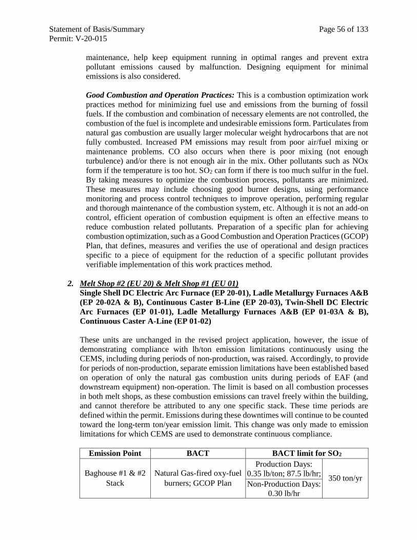
Statement of Basis/Summary Page 56 of 133
Permit: V-20-015
maintenance, help keep equipment running in optimal ranges and prevent extra
pollutant emissions caused by malfunction. Designing equipment for minimal
emissions is also considered.
Good Combustion and Operation Practices: This is a combustion optimization work
practices method for minimizing fuel use and emissions from the burning of fossil
fuels. If the combustion and combination of necessary elements are not controlled, the
combustion of the fuel is incomplete and undesirable emissions form. Particulates from
natural gas combustion are usually larger molecular weight hydrocarbons that are not
fully combusted. Increased PM emissions may result from poor air/fuel mixing or
maintenance problems. CO also occurs when there is poor mixing (not enough
turbulence) and/or there is not enough air in the mix. Other pollutants such as NOx
form if the temperature is too hot. SO2 can form if there is too much sulfur in the fuel.
By taking measures to optimize the combustion process, pollutants are minimized.
These measures may include choosing good burner designs, using performance
monitoring and process control techniques to improve operation, performing regular
and thorough maintenance of the combustion system, etc. Although it is not an add-on
control, efficient operation of combustion equipment is often an effective means to
reduce combustion related pollutants. Preparation of a specific plan for achieving
combustion optimization, such as a Good Combustion and Operation Practices (GCOP)
Plan, that defines, measures and verifies the use of operational and design practices
specific to a piece of equipment for the reduction of a specific pollutant provides
verifiable implementation of this work practices method.
2. Melt Shop #2 (EU 20) & Melt Shop #1 (EU 01)
Single Shell DC Electric Arc Furnace (EP 20-01), Ladle Metallurgy Furnaces A&B
(EP 20-02A & B), Continuous Caster B-Line (EP 20-03), Twin-Shell DC Electric
Arc Furnaces (EP 01-01), Ladle Metallurgy Furnaces A&B (EP 01-03A & B),
Continuous Caster A-Line (EP 01-02)
These units are unchanged in the revised project application, however, the issue of
demonstrating compliance with lb/ton emission limitations continuously using the
CEMS, including during periods of non-production, was raised. Accordingly, to provide
for periods of non-production, separate emission limitations have been established based
on operation of only the natural gas combustion units during periods of EAF (and
downstream equipment) non-operation. The limit is based on all combustion processes
in both melt shops, as these combustion emissions can travel freely within the building,
and cannot therefore be attributed to any one specific stack. These time periods are
defined within the permit. Emissions during these downtimes will continue to be counted
toward the long-term ton/year emission limit. This change was only made to emission
limitations for which CEMS are used to demonstrate continuous compliance.
Emission Point BACT BACT limit for SO2
Baghouse #1 & #2
Stack
Natural Gas-fired oxy-fuel
burners; GCOP Plan
Production Days:
0.35 lb/ton; 87.5 lb/hr; 350 ton/yr
Non-Production Days:
0.30 lb/hr
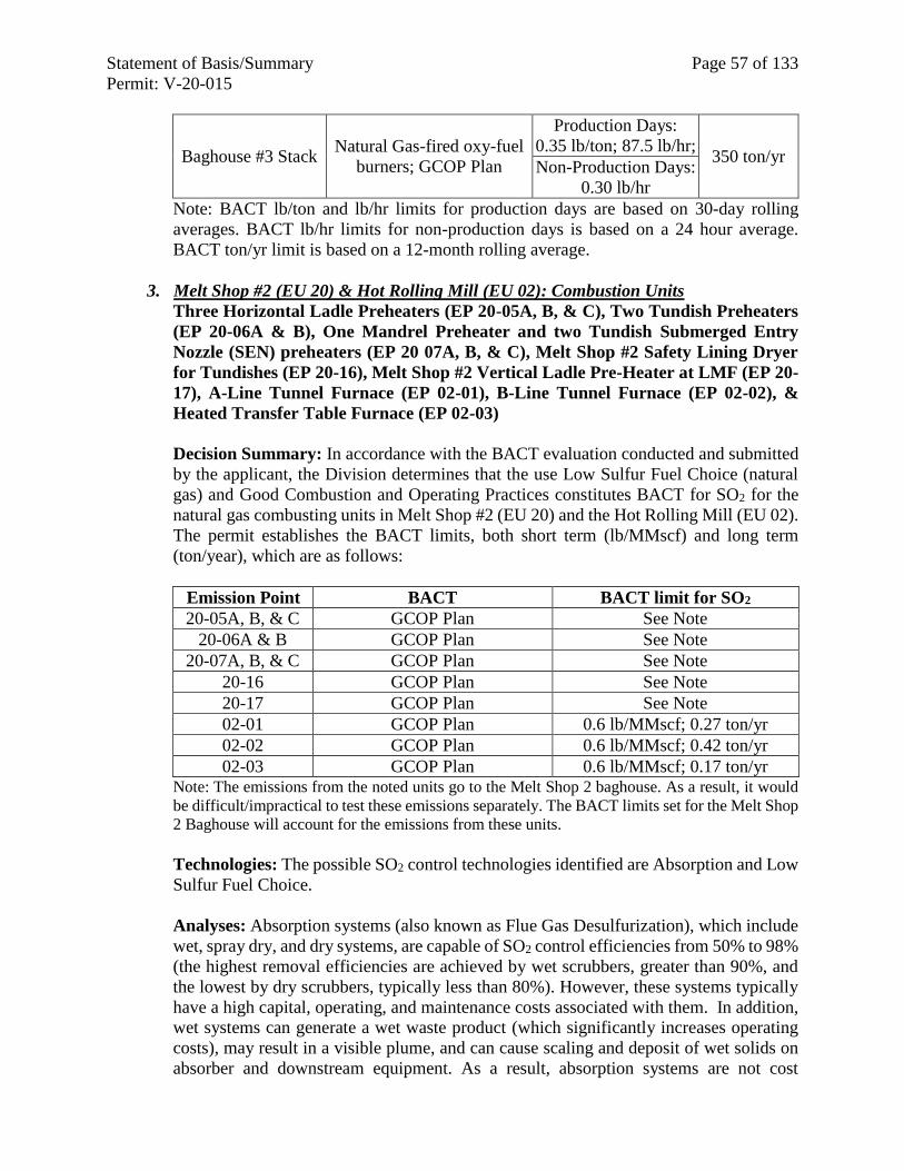
Statement of Basis/Summary Page 57 of 133
Permit: V-20-015
Baghouse #3 Stack Natural Gas-fired oxy-fuel
burners; GCOP Plan
Production Days:
0.35 lb/ton; 87.5 lb/hr; 350 ton/yr
Non-Production Days:
0.30 lb/hr
Note: BACT lb/ton and lb/hr limits for production days are based on 30-day rolling
averages. BACT lb/hr limits for non-production days is based on a 24 hour average.
BACT ton/yr limit is based on a 12-month rolling average.
3. Melt Shop #2 (EU 20) & Hot Rolling Mill (EU 02): Combustion Units
Three Horizontal Ladle Preheaters (EP 20-05A, B, & C), Two Tundish Preheaters
(EP 20-06A & B), One Mandrel Preheater and two Tundish Submerged Entry
Nozzle (SEN) preheaters (EP 20 07A, B, & C), Melt Shop #2 Safety Lining Dryer
for Tundishes (EP 20-16), Melt Shop #2 Vertical Ladle Pre-Heater at LMF (EP 20-
17), A-Line Tunnel Furnace (EP 02-01), B-Line Tunnel Furnace (EP 02-02), &
Heated Transfer Table Furnace (EP 02-03)
Decision Summary: In accordance with the BACT evaluation conducted and submitted
by the applicant, the Division determines that the use Low Sulfur Fuel Choice (natural
gas) and Good Combustion and Operating Practices constitutes BACT for SO2 for the
natural gas combusting units in Melt Shop #2 (EU 20) and the Hot Rolling Mill (EU 02).
The permit establishes the BACT limits, both short term (lb/MMscf) and long term
(ton/year), which are as follows:
Emission Point BACT BACT limit for SO2
20-05A, B, & C GCOP Plan See Note
20-06A & B GCOP Plan See Note
20-07A, B, & C GCOP Plan See Note
20-16 GCOP Plan See Note
20-17 GCOP Plan See Note
02-01 GCOP Plan 0.6 lb/MMscf; 0.27 ton/yr
02-02 GCOP Plan 0.6 lb/MMscf; 0.42 ton/yr
02-03 GCOP Plan 0.6 lb/MMscf; 0.17 ton/yr Note: The emissions from the noted units go to the Melt Shop 2 baghouse. As a result, it would
be difficult/impractical to test these emissions separately. The BACT limits set for the Melt Shop
2 Baghouse will account for the emissions from these units.
Technologies: The possible SO2 control technologies identified are Absorption and Low
Sulfur Fuel Choice.
Analyses: Absorption systems (also known as Flue Gas Desulfurization), which include
wet, spray dry, and dry systems, are capable of SO2 control efficiencies from 50% to 98%
(the highest removal efficiencies are achieved by wet scrubbers, greater than 90%, and
the lowest by dry scrubbers, typically less than 80%). However, these systems typically
have a high capital, operating, and maintenance costs associated with them. In addition,
wet systems can generate a wet waste product (which significantly increases operating
costs), may result in a visible plume, and can cause scaling and deposit of wet solids on
absorber and downstream equipment. As a result, absorption systems are not cost
Statement of Basis/Summary Page 58 of 133
Permit: V-20-015
effective to reduce to small amount of SO2 generated by natural gas combustion (these
systems are typically installed in coal- and oil-fired combustion applications).
The use low sulfur fuels is a very efficient means of SO2 control, as all of the SO2 emitted
by the natural gas combusting units in the Hot Rolling Mill and Melt Shop #2 originates
from the combusted fuel. Consequently, the potential SO2 emissions can be minimized
by combusting a fuel with a low sulfur content, such as natural gas. As a result, the use
of natural gas as a fuel for combustion is chosen as BACT for SO2.
BACT limits for SO2 from the natural gas combusting equipment in the Hot Rolling Mill
and Melt Shop #2 have been set based upon the proposed use of natural gas as fuel, the
capacity of the burners chosen, and the basic combustion emission factors found in AP-
42, Section 1.4. Short term and long term limits, i.e. maximum lb/MMscf and tpy of SO2
that may be emitted from each stack or vent, as well as natural gas use limits, have been
imposed on the equipment of the melt shop.
Initial and continuous compliance is demonstrated through monitoring, recording and
reporting gas usage for the subject equipment.
4. Emergency Generators > 500 HP (EU 08)
Emergency Generators (EPs 08-05, 08-06, and 08-07)
Decision Summary: Please note that all of the pollutant BACT analyses for the
emergency generators are contained in the Particulate BACT analysis section for this
equipment, above.
5. Air Separation Plant (EU 23)
Air Separation Plant Unit Water Bath Vaporizer (EP 23-01)
Decision Summary: In accordance with the BACT evaluation conducted and submitted
by the applicant, the Division determines that Low Sulfur Fuel Choice (natural gas) and
Good Combustion and Operating Practice constitutes BACT for SO2 for the air separation
plant. The permit establishes BACT emission limitations, both short term (lb/MMscf)
and long term (tpy). To ensure compliance with these limitations, the permit requires
recordkeeping and monitoring.
Emission Point Control Device BACT for SO2
23-01 Good Combustion and Operation Practices 0.6 lb/MMscf; 0.075 ton/yr
Technologies: The possible control technologies identified for SO2 at the air separation
plant are Low Sulfur Fuel Choice.
Analyses: After identifying possible technologies available, NSG presented a review of
the different possible technologies discussing the technical feasibility of each one and the
relevant advantages and disadvantages for use in the Air Separation Plant.
SO2 emissions are present as the result of oxidation of sulfur compounds in the fuel. By
utilizing a low sulfur fuel, such as natural gas, potential SO2 emissions are controlled.
Statement of Basis/Summary Page 59 of 133
Permit: V-20-015
As configured, the air separation plant limits emissions in a manner consistent with
current standards in the metallurgical industry. Analysis of the facilities in the RBLC
database demonstrates that virtually all vaporizers in the industry are controlled by low
sulfur fuel.
Compliance is assumed by the combustion of natural gas.
G. BACT for Fluoride (F)
B-Line Caster Spray Vent (EP 20-11)
The fluoride analysis for the Caster Spray Vent is found in the PM/PM10/PM2.5 and Pb
analysis section for this equipment.
H. BACT for GHGs
1. General Control Measures for GHGs
Although GHGs are an aggregate group of six gases, including CO2, N2O, CH4,
hydrofluorocarbons, perfluorocarbons, and sulfur hexafluoride, they are treated as a
single air pollutant for PSD and BACT purposes. NSG analyzed the methods and
technologies for reduction and/or destruction for CO2, the major GHG pollutant
component from steel casting and mini-mill facilities, as applicable for all emitted GHGs
at the proposed project.
Technologies for GHG Control: Two broad categories of possible CO2 technologies
are identified and analyzed for the project, Carbon Capture and Sequestration (CCS) and
Energy Efficiency Measures. The CCS is based on the separation and capture of CO2
from process gases and injecting the CO2 into a suitable geologic formation for long-term
storage. For an energy efficiency strategy, the focus is on thermal efficiency to reduce
the site-wide consumption of fuels and also reduce electricity use to reduce GHGs
emitted by the power utilities that supply energy to the site.
Carbon Capture and Sequestration
Carbon capture and sequestration (CCS) is the long-term isolation of fossil fuel CO2
emissions from the atmosphere through capturing and storing the CO2 deep in the
subsurface of the earth. CCS is the only potentially available add-on control option to
reduce large-scale direct emissions from industrial processes. CCS is made up of three
key stages:
Capture: Carbon capture is the separation of CO2 from other gases produced when fossil
fuels are combusted. Post-combustion CO2 separation can be performed with chemical
absorption systems using aqueous solution of amines as chemical solvents, or physical
absorption systems using methanol or other solvents.
There are three main technology categories proposed for the first step of separation and
capture: pre-combustion, oxy-fuel combustion, and post-combustion.
Statement of Basis/Summary Page 60 of 133
Permit: V-20-015
Pre-combustion involves the removal of the CO2 from a fossil fuel before it is combusted.
In this type of system, a fuel is converted to gas through heating with steam and air or
oxygen. A gas containing mainly hydrogen and CO is produced. The CO is reacted with
steam to produce CO2 and additional hydrogen. The CO2 is separated out though
physical or chemical adsorption.
Oxy-fuel combustion uses pure oxygen, instead of air, and the resulting combustion
yields gas with highly concentrated with CO2. Available technologies for producing pure
oxygen are mostly based on cryogenic separation of oxygen from air. Extreme cooling
of air produces liquid oxygen, nitrogen, and argon. The process is energy consuming
(i.e. produces GHGs at power utilities), costly, and still in the demonstration phase of
research.
Post-combustion capture involves removing and capturing CO2 from flue gas prior to
release to atmosphere. Included in this category of capture are chemical absorption,
physical absorption, calcium cycle separation, cryogenic separation, membrane
separation and adsorption. The following are Post-combustion capture technologies:
Chemical absorption is considered the best option of the post-combustion technologies
(Simonds, M., et. al., A Study of Very Large Scale Post Combustion CO2 Capture at a
Refining & Petrochemical Complex, 6th International Conference on Green House Gas
Control Technologies, Kyoto, 2002). A solvent is used at low partial pressure to separate
CO2 in flue gas. Drawbacks for this include the corrosive nature of the solvent in the
presence of oxygen, high solvent degradation rates (highly reactive with SO2 and NOx)
and the energy required for solvent regeneration.
Physical absorption uses a solvent at high pressure and low temperature and is typically
used for CO2 removal from natural gas. The low CO2 concentration in flue gas makes
this process unsuitable for use with heat recovery coking processes. The flue gas would
have to be strongly compressed to achieve the reaction and would require significant
energy to function properly, off-setting any reduction in CO2 emissions.
Calcium cycle separation is still in the research and testing phase. This technology uses
quicklime to yield limestone. The limestone is heated to release CO2 and produce
quicklime, again, for recycling. Performance, cost and commercial viability are not yet
established (Mackenzie, A., et. al., Economics of CO2 Capture Using the Calcium Cycle
with a Pressurized Fluidized Bed Combustor).
Cryogenic separation is widely used for purification of CO2 from streams that have high
concentration of CO2. This technology is based on solidifying CO2 by frosting and
separating it out.
Gas separation membranes may be used to selectively transport gases through the film.
This technology is used mainly for CO2 removal from natural gas at high pressure and
high concentrations of CO2. It is a new technology for this application and has not been
optimized for large scale applications (CO2 Capture and Storage: A VGB Report on the
State of the Art, VGB Power Tech, 2004). Low concentrations of CO2 in the flue gas
would make this technology uneconomical for use.
Statement of Basis/Summary Page 61 of 133
Permit: V-20-015
Adsorption of CO2 can be accomplished by passing flue gas through a bed of solid
material, such as activated carbon. Adsorption requires high compression or multiple
separation steps and is not applicable for industrial operations, yet (VGB Power Tech,
2004).
In fact, most of these technologies have been developed for use with higher CO2 emitting
fuels, such as coal, and are not well suited for use with smaller natural gas combusting
units and groups. Lower concentrations of CO2 in flue gases to treat and the high energy
costs for these technologies make them uneconomical and impractical for the NSG
project.
Other less developed technologies, including aqueous ammonia wet scrubbing, solid
sorbents, metal organic frameworks, enzyme-based systems and ionic liquids, are not
mature enough to be commercially available.
Along with separation/capture technologies, the transportation and sequestration of the
CO2 must also be accomplished to truly reduce GHGs. The captured CO2 must either be
reused or liquefied, transported, and permanently stored.
Transport: After separation, CO2 is compressed to facilitate transportation and storage
if a locally available site for direct injection is unavailable. After compression, CO2 is
transported utilizing a third-party CO2 pipeline system to transport CO2 to distant
geologic formations that may be more conducive to sequestration than sites in the
immediate area.
Pipelines are the most common method of transporting large amount of CO2 over long
distances. The gas must be compressed under high pressure for pipeline transport, which
requires high energy consumption. Water must be eliminated from the pipeline to prevent
the formation of corrosive carbonic acid. Booster compressors along the pipeline may be
needed to maintain the pressure along the long lengths of transport pipe. Pipelines must
also be maintained to prevent CO2 escape. There are around 50 CO2 pipelines in the U.S.,
mostly in the Western states. Many of the CO2 pipelines connect sources with specific
customers.
Building transport facilities, such a pipeline for dedicated use by a single facility, will
make many projects economically infeasible, both from an absolute and BACT review
perspective. However, such an option may be effective only if adequate storage capacity
exists downstream and reasonable transportation prices can be arranged with the pipeline
operator.
Storage: At a storage site, CO2 is injected into deep underground rock formations, often
at depths of one (1) km or more. Storage options for the CO2 are still under development.
These include storage in geological formations, such as exhausted oil fields, saline
formations, under ocean liquid storage, solid carbonate storage, and terrestrial
sequestration. These storage sites generally have an impermeable rock above them, with
seals and other geologic features to prevent CO2 from returning to the surface.
Monitoring, reporting, and verifying are important to demonstrate that CO2 is safely
Statement of Basis/Summary Page 62 of 133
Permit: V-20-015
stored. A partnership of the U.S. Department of Energy (DOE), Office of Fossil Energy
(FE), and National Energy Technology Laboratory (NETL) Energy is currently working
on seven CO2 storage projects in the United States. In 2017, the ADM Illinois Industrial
Carbon Capture & Storage Project successfully began capturing CO2 from an ethanol
production facility and sequestering it in a deep saline formation.
Despite the recent research and activity, the CCS technology is still cost prohibitive for
facilities emitting relatively smaller amounts of CO2. In the United States, only one large-
scale, fossil-fueled power plant, Petra Nova in Texas, is using CCS. The plant offsets
some of the costs of the technology through selling CO2 for use in oil recovery.
A recent Congressional Research Service report (Folger, August 9, 2018) states that
“There is a broad agreement that costs for CCS would need to decrease before the
technologies could be deployed commercially across the nation.”
Energy Efficiency Measures
Thermal efficiency is an emissions reduction strategy focused on increasing energy
efficiency. Energy efficient processes reduce the amount of fuel consumed. Reductions
in fuel consumption result in reductions of direct emissions of GHGs at the steel plant,
and reductions in electricity usage result in reductions of indirect GHG emissions. Many
operating practices of an EAF affect the energy efficiency including stirring method,
addition of oxy-fuel burners, and material preheating.
In general, for energy efficiency measures, the plant design and work practices would be
planned to reduce fuel usage (on and off-site), use less polluting fuels, and use more
efficient combustion equipment. These measures include development of a Good
Combustion and Operation Practices plan, Fuel Selection, Good Equipment Design,
Good Material Selection/Substitution.
Since the separation, capture and sequestration technologies are either not-feasible, and
may be cost prohibitive (Cost and Performance of Carbon Dioxide Capture from Power
Generation Working Paper, IEA, 2011) the Division finds selection of Energy Efficiency
Measures acceptable as BACT for control of GHG emissions for the NSG Project.
2. Melt Shop #2 (EU 20) & Melt Shop #1 (EU 01)
Single Shell DC Electric Arc Furnace (EP 20-01), Ladle Metallurgy Furnaces A&B
(EP 20-02A & B), Continuous Caster B-Line (EP 20-03), Twin-Shell DC Electric
Arc Furnaces (EP 01-01), Ladle Metallurgy Furnaces A&B (EP 01-03A & B),
Continuous Caster A-Line (EP 01-02)
Decision Summary: In accordance with the BACT evaluation conducted and submitted
by the applicant, the Division determines that the development of a Good Combustion
and Operation Practices (GCOP) Plan, as well as the use of natural gas, constitutes BACT
for GHG for the natural gas combusting units in the Hot Rolling Mill and Melt Shop 2.
Specific work practices are unchanged from the initial permitting action and are in the
permit, however, they are not reiterated here. The permit establishes the BACT limits,
which are as follows:
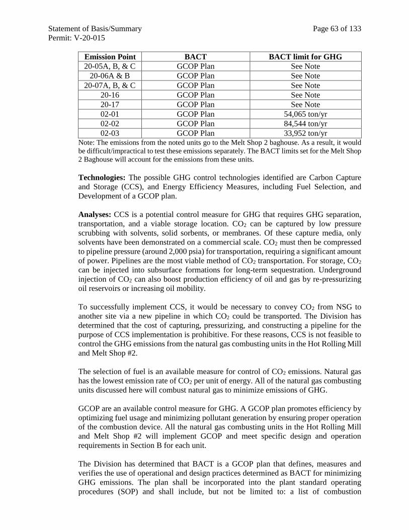
Statement of Basis/Summary Page 63 of 133
Permit: V-20-015
Emission Point BACT BACT limit for GHG
20-05A, B, & C GCOP Plan See Note
20-06A & B GCOP Plan See Note
20-07A, B, & C GCOP Plan See Note
20-16 GCOP Plan See Note
20-17 GCOP Plan See Note
02-01 GCOP Plan 54,065 ton/yr
02-02 GCOP Plan 84,544 ton/yr
02-03 GCOP Plan 33,952 ton/yr Note: The emissions from the noted units go to the Melt Shop 2 baghouse. As a result, it would
be difficult/impractical to test these emissions separately. The BACT limits set for the Melt Shop
2 Baghouse will account for the emissions from these units.
Technologies: The possible GHG control technologies identified are Carbon Capture
and Storage (CCS), and Energy Efficiency Measures, including Fuel Selection, and
Development of a GCOP plan.
Analyses: CCS is a potential control measure for GHG that requires GHG separation,
transportation, and a viable storage location. CO2 can be captured by low pressure
scrubbing with solvents, solid sorbents, or membranes. Of these capture media, only
solvents have been demonstrated on a commercial scale. CO2 must then be compressed
to pipeline pressure (around 2,000 psia) for transportation, requiring a significant amount
of power. Pipelines are the most viable method of CO2 transportation. For storage, CO2
can be injected into subsurface formations for long-term sequestration. Underground
injection of CO2 can also boost production efficiency of oil and gas by re-pressurizing
oil reservoirs or increasing oil mobility.
To successfully implement CCS, it would be necessary to convey CO2 from NSG to
another site via a new pipeline in which CO2 could be transported. The Division has
determined that the cost of capturing, pressurizing, and constructing a pipeline for the
purpose of CCS implementation is prohibitive. For these reasons, CCS is not feasible to
control the GHG emissions from the natural gas combusting units in the Hot Rolling Mill
and Melt Shop #2.
The selection of fuel is an available measure for control of CO2 emissions. Natural gas
has the lowest emission rate of CO2 per unit of energy. All of the natural gas combusting
units discussed here will combust natural gas to minimize emissions of GHG.
GCOP are an available control measure for GHG. A GCOP plan promotes efficiency by
optimizing fuel usage and minimizing pollutant generation by ensuring proper operation
of the combustion device. All the natural gas combusting units in the Hot Rolling Mill
and Melt Shop #2 will implement GCOP and meet specific design and operation
requirements in Section B for each unit.
The Division has determined that BACT is a GCOP plan that defines, measures and
verifies the use of operational and design practices determined as BACT for minimizing
GHG emissions. The plan shall be incorporated into the plant standard operating
procedures (SOP) and shall include, but not be limited to: a list of combustion
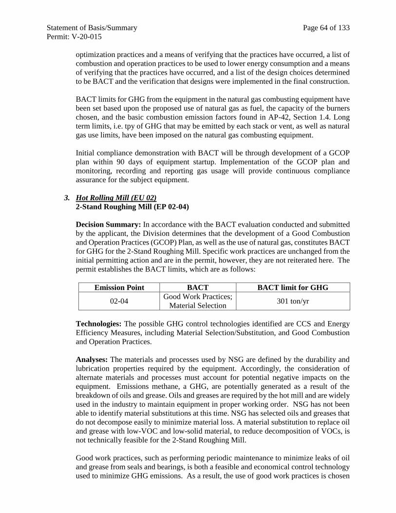
Statement of Basis/Summary Page 64 of 133
Permit: V-20-015
optimization practices and a means of verifying that the practices have occurred, a list of
combustion and operation practices to be used to lower energy consumption and a means
of verifying that the practices have occurred, and a list of the design choices determined
to be BACT and the verification that designs were implemented in the final construction.
BACT limits for GHG from the equipment in the natural gas combusting equipment have
been set based upon the proposed use of natural gas as fuel, the capacity of the burners
chosen, and the basic combustion emission factors found in AP-42, Section 1.4. Long
term limits, i.e. tpy of GHG that may be emitted by each stack or vent, as well as natural
gas use limits, have been imposed on the natural gas combusting equipment.
Initial compliance demonstration with BACT will be through development of a GCOP
plan within 90 days of equipment startup. Implementation of the GCOP plan and
monitoring, recording and reporting gas usage will provide continuous compliance
assurance for the subject equipment.
3. Hot Rolling Mill (EU 02)
2-Stand Roughing Mill (EP 02-04)
Decision Summary: In accordance with the BACT evaluation conducted and submitted
by the applicant, the Division determines that the development of a Good Combustion
and Operation Practices (GCOP) Plan, as well as the use of natural gas, constitutes BACT
for GHG for the 2-Stand Roughing Mill. Specific work practices are unchanged from the
initial permitting action and are in the permit, however, they are not reiterated here. The
permit establishes the BACT limits, which are as follows:
Emission Point BACT BACT limit for GHG
02-04 Good Work Practices;
Material Selection 301 ton/yr
Technologies: The possible GHG control technologies identified are CCS and Energy
Efficiency Measures, including Material Selection/Substitution, and Good Combustion
and Operation Practices.
Analyses: The materials and processes used by NSG are defined by the durability and
lubrication properties required by the equipment. Accordingly, the consideration of
alternate materials and processes must account for potential negative impacts on the
equipment. Emissions methane, a GHG, are potentially generated as a result of the
breakdown of oils and grease. Oils and greases are required by the hot mill and are widely
used in the industry to maintain equipment in proper working order. NSG has not been
able to identify material substitutions at this time. NSG has selected oils and greases that
do not decompose easily to minimize material loss. A material substitution to replace oil
and grease with low-VOC and low-solid material, to reduce decomposition of VOCs, is
not technically feasible for the 2-Stand Roughing Mill.
Good work practices, such as performing periodic maintenance to minimize leaks of oil
and grease from seals and bearings, is both a feasible and economical control technology
used to minimize GHG emissions. As a result, the use of good work practices is chosen
Statement of Basis/Summary Page 65 of 133
Permit: V-20-015
as BACT for the 2-Stand Roughing Mill.
BACT limitations were set based on projected emissions using approved emission factors
and known throughputs.
Initial and continuous compliance for the 2-Stand Roughing Mill is demonstrated through
monitoring, recording and reporting throughputs for the equipment.
4. Emergency Generators > 500 HP (EU 08)
Emergency Generators (EPs 08-05, 08-06, and 08-07)
Decision Summary: In accordance with the BACT evaluation conducted and submitted
by the applicant the Division determines that the development of a Good Combustion
and Operation Practices (GCOP) plan constitutes GHG BACT for the Emergency
Generators.
Technologies: Possible technologies identified for use with the new Emergency
Generators (both more and less than 500 HP) CCS, Energy Efficiency Measures,
including Energy Efficient Design, and a GCOP.
Analyses: As discussed in other analyses, above, the use of an add-on technology is
neither practical nor cost effective for the limited-use emergency diesel generators on the
NSG site.
Energy efficient design results in lower emissions by virtue of using less fuel in order to
accomplish the same amount of work. In addition, following equipment specific Good
Combustion Operation Practices also optimizes engine operation and diminishes fuel use.
By using less fuel via increasing the efficiency, all emissions are minimized.
Initial and continuing compliance with the BACT is demonstrated by purchasing engines
certified to the criteria required under 401 KAR 60:005, Section 2(2)(dddd), 40 C.F.R.
60.4200 to 60.4219, Tables 1 to 8 (Subpart IIII), Standards of Performance for
Stationary Compression Ignition Internal Combustion Engines (CI ICE) and/or 401
KAR 63:002, Section 2(4)(eeee), 40 C.F.R. 63.6580 to 63.6675, Tables 1a to 8, and
Appendix A (Subpart ZZZZ), National Emissions Standards for Hazardous Air
Pollutants for Stationary Reciprocating Internal Combustion Engines (RICE), as
applicable for the size of the engine and development and implementation of a GCOP
plan.
5. Air Separation Plant (EU 23)
Air Separation Plant Unit Water Bath Vaporizer (EP 23-01)
Decision Summary: In accordance with the BACT evaluation conducted and submitted
by the applicant, the Division determines that the use of energy efficient design
constitutes BACT for GHG for the air separation plant. The permit establishes BACT
emission limitations as long term (tpy). To ensure compliance with these limitations, the
permit requires recordkeeping and monitoring. Specific work practices are unchanged
from the initial permitting action and are in the permit, however, they are not reiterated
here. The permit establishes the BACT limits, which are as follows:
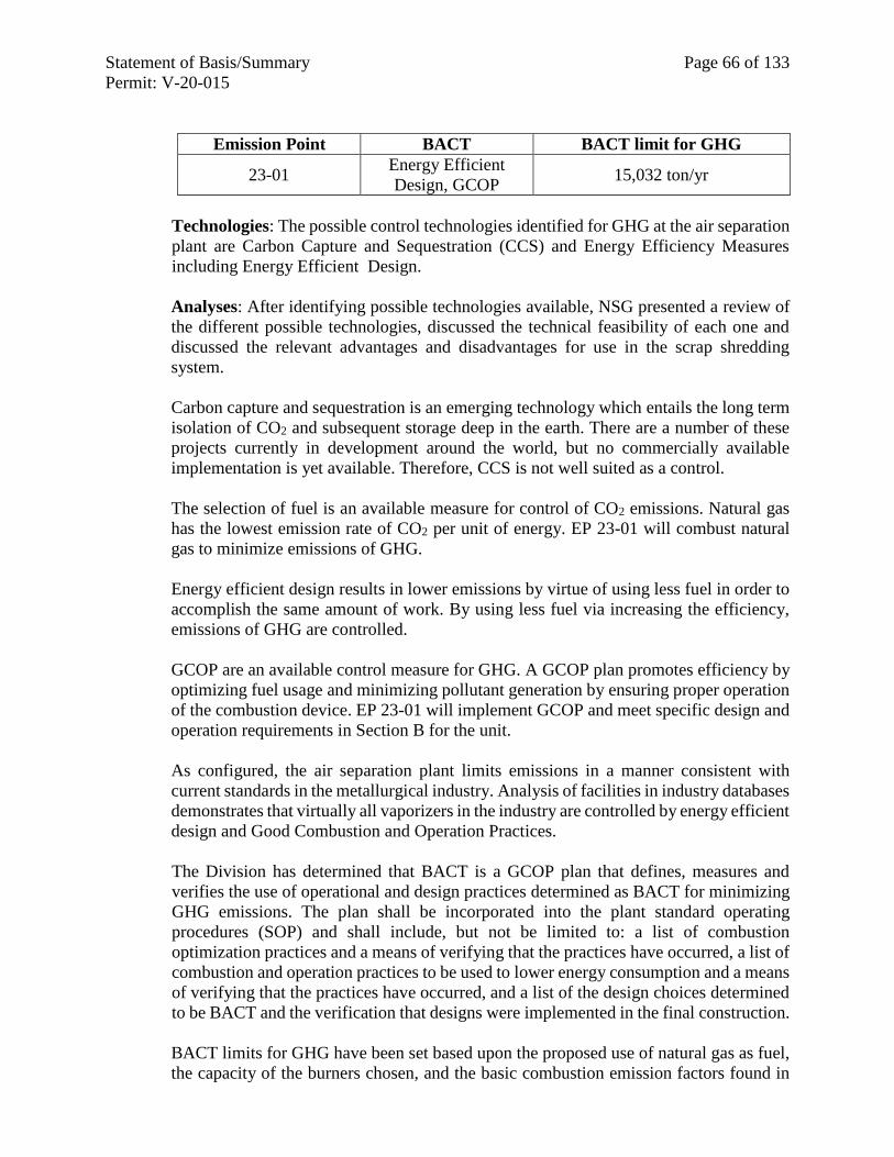
Statement of Basis/Summary Page 66 of 133
Permit: V-20-015
Emission Point BACT BACT limit for GHG
23-01 Energy Efficient
Design, GCOP 15,032 ton/yr
Technologies: The possible control technologies identified for GHG at the air separation
plant are Carbon Capture and Sequestration (CCS) and Energy Efficiency Measures
including Energy Efficient Design.
Analyses: After identifying possible technologies available, NSG presented a review of
the different possible technologies, discussed the technical feasibility of each one and
discussed the relevant advantages and disadvantages for use in the scrap shredding
system.
Carbon capture and sequestration is an emerging technology which entails the long term
isolation of CO2 and subsequent storage deep in the earth. There are a number of these
projects currently in development around the world, but no commercially available
implementation is yet available. Therefore, CCS is not well suited as a control.
The selection of fuel is an available measure for control of CO2 emissions. Natural gas
has the lowest emission rate of CO2 per unit of energy. EP 23-01 will combust natural
gas to minimize emissions of GHG.
Energy efficient design results in lower emissions by virtue of using less fuel in order to
accomplish the same amount of work. By using less fuel via increasing the efficiency,
emissions of GHG are controlled.
GCOP are an available control measure for GHG. A GCOP plan promotes efficiency by
optimizing fuel usage and minimizing pollutant generation by ensuring proper operation
of the combustion device. EP 23-01 will implement GCOP and meet specific design and
operation requirements in Section B for the unit.
As configured, the air separation plant limits emissions in a manner consistent with
current standards in the metallurgical industry. Analysis of facilities in industry databases
demonstrates that virtually all vaporizers in the industry are controlled by energy efficient
design and Good Combustion and Operation Practices.
The Division has determined that BACT is a GCOP plan that defines, measures and
verifies the use of operational and design practices determined as BACT for minimizing
GHG emissions. The plan shall be incorporated into the plant standard operating
procedures (SOP) and shall include, but not be limited to: a list of combustion
optimization practices and a means of verifying that the practices have occurred, a list of
combustion and operation practices to be used to lower energy consumption and a means
of verifying that the practices have occurred, and a list of the design choices determined
to be BACT and the verification that designs were implemented in the final construction.
BACT limits for GHG have been set based upon the proposed use of natural gas as fuel,
the capacity of the burners chosen, and the basic combustion emission factors found in
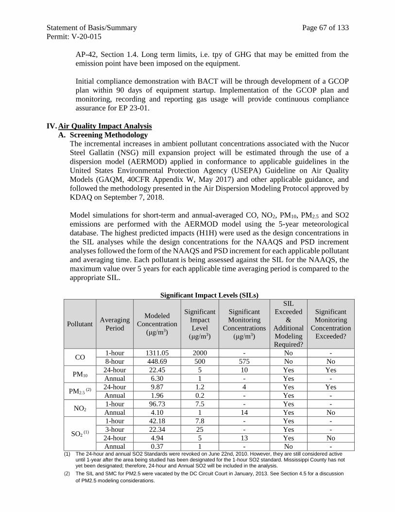
Statement of Basis/Summary Page 67 of 133
Permit: V-20-015
AP-42, Section 1.4. Long term limits, i.e. tpy of GHG that may be emitted from the
emission point have been imposed on the equipment.
Initial compliance demonstration with BACT will be through development of a GCOP
plan within 90 days of equipment startup. Implementation of the GCOP plan and
monitoring, recording and reporting gas usage will provide continuous compliance
assurance for EP 23-01.
IV. Air Quality Impact Analysis
A. Screening Methodology
The incremental increases in ambient pollutant concentrations associated with the Nucor
Steel Gallatin (NSG) mill expansion project will be estimated through the use of a
dispersion model (AERMOD) applied in conformance to applicable guidelines in the
United States Environmental Protection Agency (USEPA) Guideline on Air Quality
Models (GAQM, 40CFR Appendix W, May 2017) and other applicable guidance, and
followed the methodology presented in the Air Dispersion Modeling Protocol approved by
KDAQ on September 7, 2018.
Model simulations for short-term and annual-averaged CO, NO2, PM10, PM2.5 and SO2
emissions are performed with the AERMOD model using the 5-year meteorological
database. The highest predicted impacts (H1H) were used as the design concentrations in
the SIL analyses while the design concentrations for the NAAQS and PSD increment
analyses followed the form of the NAAQS and PSD increment for each applicable pollutant
and averaging time. Each pollutant is being assessed against the SIL for the NAAQS, the
maximum value over 5 years for each applicable time averaging period is compared to the
appropriate SIL.
Significant Impact Levels (SILs)
Pollutant Averaging
Period
Modeled
Concentration
(μg/m3)
Significant
Impact
Level
(μg/m3)
Significant
Monitoring
Concentrations
(μg/m3)
SIL
Exceeded
&
Additional
Modeling
Required?
Significant
Monitoring
Concentration
Exceeded?
CO 1-hour 1311.05 2000 - No -
8-hour 448.69 500 575 No No
PM10 24-hour 22.45 5 10 Yes Yes
Annual 6.30 1 - Yes -
PM2.5 (2)
24-hour 9.87 1.2 4 Yes Yes
Annual 1.96 0.2 - Yes -
NO2 1-hour 96.73 7.5 - Yes -
Annual 4.10 1 14 Yes No
SO2 (1)
1-hour 42.18 7.8 - Yes -
3-hour 22.34 25 - Yes -
24-hour 4.94 5 13 Yes No
Annual 0.37 1 - No - (1) The 24-hour and annual SO2 Standards were revoked on June 22nd, 2010. However, they are still considered active
until 1-year after the area being studied has been designated for the 1-hour SO2 standard. Mississippi County has not yet been designated; therefore, 24-hour and Annual SO2 will be included in the analysis.
(2) The SIL and SMC for PM2.5 were vacated by the DC Circuit Court in January, 2013. See Section 4.5 for a discussion
of PM2.5 modeling considerations.
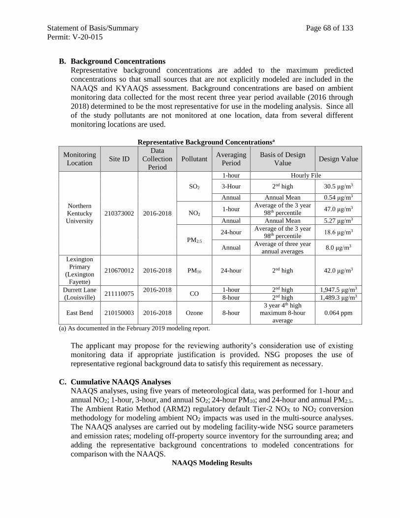
Statement of Basis/Summary Page 68 of 133
Permit: V-20-015
B. Background Concentrations
Representative background concentrations are added to the maximum predicted
concentrations so that small sources that are not explicitly modeled are included in the
NAAQS and KYAAQS assessment. Background concentrations are based on ambient
monitoring data collected for the most recent three year period available (2016 through
2018) determined to be the most representative for use in the modeling analysis. Since all
of the study pollutants are not monitored at one location, data from several different
monitoring locations are used.
Representative Background Concentrationsa
Monitoring
Location Site ID
Data
Collection
Period
Pollutant Averaging
Period
Basis of Design
Value Design Value
Northern
Kentucky
University
210373002 2016-2018
SO2
1-hour Hourly File
3-Hour 2nd high 30.5 μg/m3
Annual Annual Mean 0.54 μg/m3
NO2 1-hour
Average of the 3 year
98th percentile 47.0 μg/m3
Annual Annual Mean 5.27 μg/m3
PM2.5
24-hour Average of the 3 year
98th percentile 18.6 μg/m3
Annual Average of three year
annual averages 8.0 μg/m3
Lexington
Primary
(Lexington
Fayette)
210670012 2016-2018 PM10 24-hour 2nd high 42.0 μg/m3
Durrett Lane
(Louisville) 211110075
2016-2018
CO
1-hour 2nd high 1,947.5 μg/m3
8-hour 2nd high 1,489.3 μg/m3
East Bend 210150003 2016-2018 Ozone 8-hour
3 year 4th high
maximum 8-hour
average
0.064 ppm
(a) As documented in the February 2019 modeling report.
The applicant may propose for the reviewing authority’s consideration use of existing
monitoring data if appropriate justification is provided. NSG proposes the use of
representative regional background data to satisfy this requirement as necessary.
C. Cumulative NAAQS Analyses
NAAQS analyses, using five years of meteorological data, was performed for 1-hour and
annual NO2; 1-hour, 3-hour, and annual SO2; 24-hour PM10; and 24-hour and annual PM2.5.
The Ambient Ratio Method (ARM2) regulatory default Tier-2 NOX to NO2 conversion
methodology for modeling ambient NO2 impacts was used in the multi-source analyses.
The NAAQS analyses are carried out by modeling facility-wide NSG source parameters
and emission rates; modeling off-property source inventory for the surrounding area; and
adding the representative background concentrations to modeled concentrations for
comparison with the NAAQS. NAAQS Modeling Results
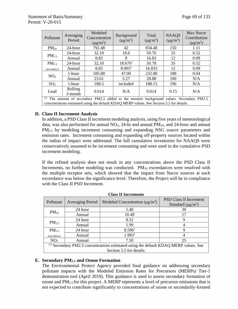
Statement of Basis/Summary Page 69 of 133
Permit: V-20-015
Pollutant Averaging
Period
Modeled
Concentration
(μg/m3)
Background
(μg/m3)
Total
(μg/m3)
NAAQS
(μg/m3)
Max Nucor
Contribution
(μg/m3)
PM10 24-hour 792.48 42 834.48 150 1.11
PM2.5 24-hour 32.10 18.6 50.70 35 0.52 Annual 8.83 8 16.83 12 0.09
PM2.5
(secondary)
24-hour 32.10 18.6761 50.78 35 0.52 Annual 8.83 8.0031 16.833 12 0.09
NO2 1-hour 185.88 47.00 232.88 188 0.04
Annual 23.61 5.27 28.88 100 N/A SO2 1-hour 188.5 included 188.15 196 N/A
Lead Rolling
3-month 0.014 N/A 0.014 0.15 N/A
(1) The amount of secondary PM2.5 added to the monitor background values. Secondary PM2.5
concentrations estimated using the default KDAQ MERP values. See Section 5.5 for details.
D. Class II Increment Analysis
In addition, a PSD Class II increment modeling analysis, using five years of meteorological
data, was also performed for annual NO2, 24-hr and annual PM10, and 24-hour and annual
PM2.5 by modeling increment consuming and expanding NSG source parameters and
emission rates. Increment consuming and expanding off-property sources located within
the radius of impact were addressed. The full cumulative inventories for NAAQS were
conservatively assumed to be increment consuming and were used in the cumulative PSD
increment modeling.
If the refined analysis does not result in any concentrations above the PSD Class II
Increments, no further modeling was conducted. PM10 exceedances were resolved with
the multiple receptor sets, which showed that the impact from Nucor sources at each
exceedance was below the significance level. Therefore, the Project will be in compliance
with the Class II PSD Increment.
Class II Increments
Pollutant Averaging Period Modeled Concentration (μg/m3) PSD Class II Increment
Standard (μg/m3)
PM10 24 hour 1.40 30
Annual 10.49 17
PM2.5 24 hour 8.52 9
Annual 1.99 4
PM2.5
(secondary)
24 hour 8.5961 9
Annual 1.9931 4
NO2 Annual 7.50 25 (1) Secondary PM2.5 concentrations estimated using the default KDAQ MERP values. See
Section 5.5 for details.
E. Secondary PM2.5 and Ozone Formation
The Environmental Protect Agency provided final guidance on addressing secondary
pollutant impacts with the Modeled Emission Rates for Precursors (MERPs) Tier-1
demonstration tool (April 2019). This guidance is used to assess secondary formation of
ozone and PM2.5 for this project. A MERP represents a level of precursor emissions that is
not expected to contribute significantly to concentrations of ozone or secondarily-formed
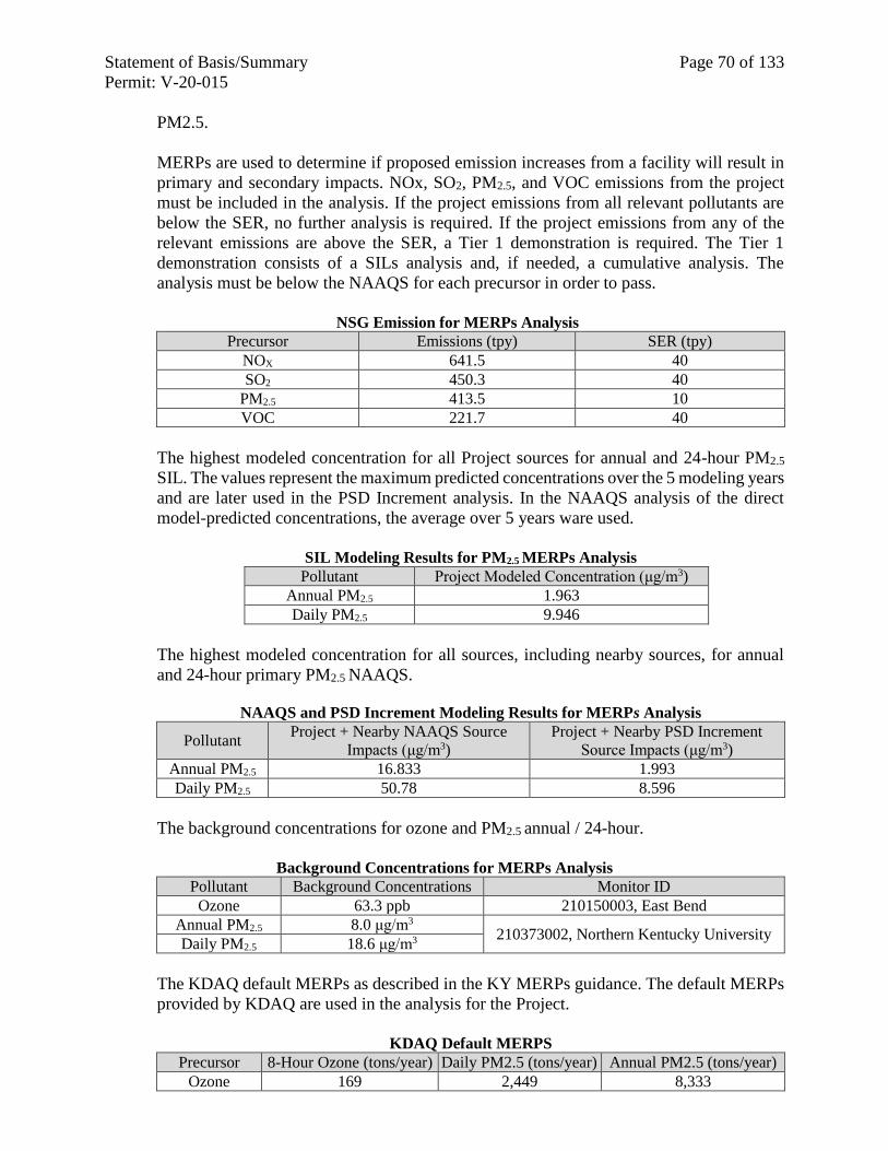
Statement of Basis/Summary Page 70 of 133
Permit: V-20-015
PM2.5.
MERPs are used to determine if proposed emission increases from a facility will result in
primary and secondary impacts. NOx, SO2, PM2.5, and VOC emissions from the project
must be included in the analysis. If the project emissions from all relevant pollutants are
below the SER, no further analysis is required. If the project emissions from any of the
relevant emissions are above the SER, a Tier 1 demonstration is required. The Tier 1
demonstration consists of a SILs analysis and, if needed, a cumulative analysis. The
analysis must be below the NAAQS for each precursor in order to pass.
NSG Emission for MERPs Analysis
Precursor Emissions (tpy) SER (tpy)
NOX 641.5 40
SO2 450.3 40
PM2.5 413.5 10
VOC 221.7 40
The highest modeled concentration for all Project sources for annual and 24-hour PM2.5
SIL. The values represent the maximum predicted concentrations over the 5 modeling years
and are later used in the PSD Increment analysis. In the NAAQS analysis of the direct
model-predicted concentrations, the average over 5 years ware used.
SIL Modeling Results for PM2.5 MERPs Analysis
Pollutant Project Modeled Concentration (μg/m3)
Annual PM2.5 1.963
Daily PM2.5 9.946
The highest modeled concentration for all sources, including nearby sources, for annual
and 24-hour primary PM2.5 NAAQS.
NAAQS and PSD Increment Modeling Results for MERPs Analysis
Pollutant Project + Nearby NAAQS Source
Impacts (μg/m3)
Project + Nearby PSD Increment
Source Impacts (μg/m3)
Annual PM2.5 16.833 1.993
Daily PM2.5 50.78 8.596
The background concentrations for ozone and PM2.5 annual / 24-hour.
Background Concentrations for MERPs Analysis
Pollutant Background Concentrations Monitor ID
Ozone 63.3 ppb 210150003, East Bend
Annual PM2.5 8.0 μg/m3 210373002, Northern Kentucky University
Daily PM2.5 18.6 μg/m3
The KDAQ default MERPs as described in the KY MERPs guidance. The default MERPs
provided by KDAQ are used in the analysis for the Project.
KDAQ Default MERPS
Precursor 8-Hour Ozone (tons/year) Daily PM2.5 (tons/year) Annual PM2.5 (tons/year)
Ozone 169 2,449 8,333
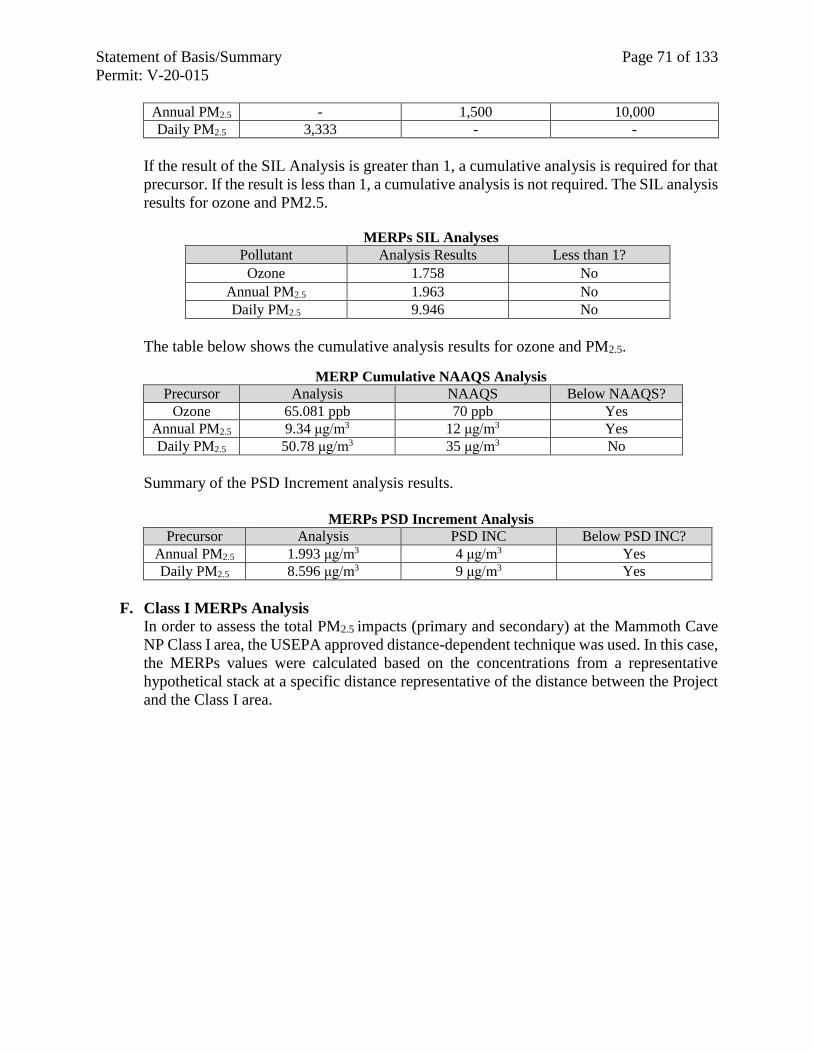
Statement of Basis/Summary Page 71 of 133
Permit: V-20-015
Annual PM2.5 - 1,500 10,000
Daily PM2.5 3,333 - -
If the result of the SIL Analysis is greater than 1, a cumulative analysis is required for that
precursor. If the result is less than 1, a cumulative analysis is not required. The SIL analysis
results for ozone and PM2.5.
MERPs SIL Analyses
Pollutant Analysis Results Less than 1?
Ozone 1.758 No
Annual PM2.5 1.963 No
Daily PM2.5 9.946 No
The table below shows the cumulative analysis results for ozone and PM2.5.
MERP Cumulative NAAQS Analysis
Precursor Analysis NAAQS Below NAAQS?
Ozone 65.081 ppb 70 ppb Yes
Annual PM2.5 9.34 μg/m3 12 μg/m3 Yes
Daily PM2.5 50.78 μg/m3 35 μg/m3 No
Summary of the PSD Increment analysis results.
MERPs PSD Increment Analysis
Precursor Analysis PSD INC Below PSD INC?
Annual PM2.5 1.993 μg/m3 4 μg/m3 Yes
Daily PM2.5 8.596 μg/m3 9 μg/m3 Yes
F. Class I MERPs Analysis
In order to assess the total PM2.5 impacts (primary and secondary) at the Mammoth Cave
NP Class I area, the USEPA approved distance-dependent technique was used. In this case,
the MERPs values were calculated based on the concentrations from a representative
hypothetical stack at a specific distance representative of the distance between the Project
and the Class I area.
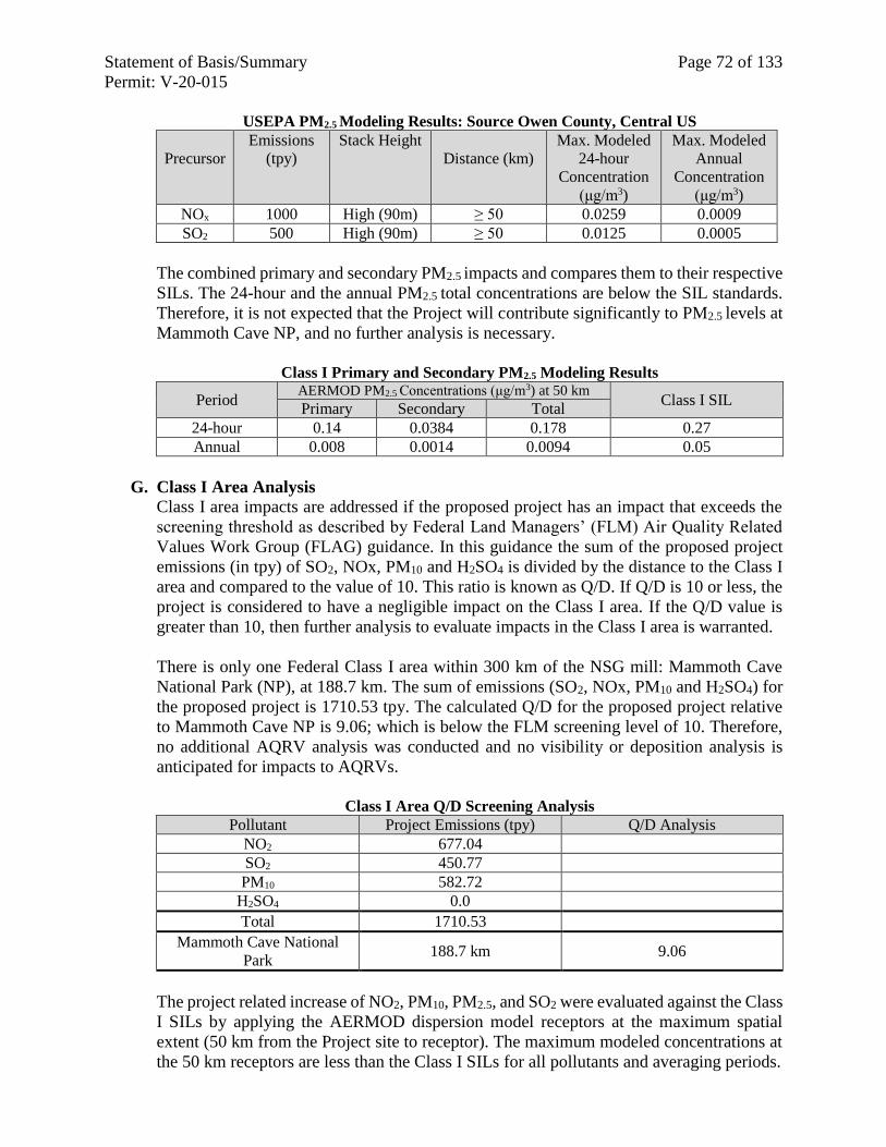
Statement of Basis/Summary Page 72 of 133
Permit: V-20-015
USEPA PM2.5 Modeling Results: Source Owen County, Central US
Precursor
Emissions
(tpy)
Stack Height
Distance (km)
Max. Modeled
24-hour
Concentration
(μg/m3)
Max. Modeled
Annual
Concentration
(μg/m3)
NOx 1000 High (90m) ≥ 50 0.0259 0.0009
SO2 500 High (90m) ≥ 50 0.0125 0.0005
The combined primary and secondary PM2.5 impacts and compares them to their respective
SILs. The 24-hour and the annual PM2.5 total concentrations are below the SIL standards.
Therefore, it is not expected that the Project will contribute significantly to PM2.5 levels at
Mammoth Cave NP, and no further analysis is necessary.
Class I Primary and Secondary PM2.5 Modeling Results
Period AERMOD PM2.5 Concentrations (μg/m3) at 50 km
Class I SIL Primary Secondary Total
24-hour 0.14 0.0384 0.178 0.27
Annual 0.008 0.0014 0.0094 0.05
G. Class I Area Analysis Class I area impacts are addressed if the proposed project has an impact that exceeds the
screening threshold as described by Federal Land Managers’ (FLM) Air Quality Related
Values Work Group (FLAG) guidance. In this guidance the sum of the proposed project
emissions (in tpy) of SO2, NOx, PM10 and H2SO4 is divided by the distance to the Class I
area and compared to the value of 10. This ratio is known as Q/D. If Q/D is 10 or less, the
project is considered to have a negligible impact on the Class I area. If the Q/D value is
greater than 10, then further analysis to evaluate impacts in the Class I area is warranted.
There is only one Federal Class I area within 300 km of the NSG mill: Mammoth Cave
National Park (NP), at 188.7 km. The sum of emissions (SO2, NOx, PM10 and H2SO4) for
the proposed project is 1710.53 tpy. The calculated Q/D for the proposed project relative
to Mammoth Cave NP is 9.06; which is below the FLM screening level of 10. Therefore,
no additional AQRV analysis was conducted and no visibility or deposition analysis is
anticipated for impacts to AQRVs.
Class I Area Q/D Screening Analysis
Pollutant Project Emissions (tpy) Q/D Analysis
NO2 677.04
SO2 450.77
PM10 582.72
H2SO4 0.0
Total 1710.53
Mammoth Cave National
Park 188.7 km 9.06
The project related increase of NO2, PM10, PM2.5, and SO2 were evaluated against the Class
I SILs by applying the AERMOD dispersion model receptors at the maximum spatial
extent (50 km from the Project site to receptor). The maximum modeled concentrations at
the 50 km receptors are less than the Class I SILs for all pollutants and averaging periods.
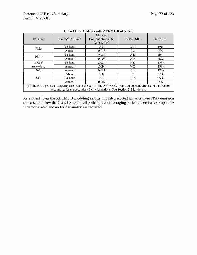
Statement of Basis/Summary Page 73 of 133
Permit: V-20-015
Class I SIL Analysis with AERMOD at 50 km
Pollutant Averaging Period
Modeled
Concentration at 50
km (μg/m3)
Class I SIL
% of SIL
PM10 24-hour 0.24 0.3 80%
Annual 0.013 0.2 7%
PM2.5 24-hour 0.014 0.27 5%
Annual 0.008 0.05 16%
PM2.51
secondary
24-hour .0524 0.27 19%
Annual .0094 0.05 19%
NO2 Annual 0.017 0.1 17%
SO2
3-hour 0.82 1 82%
24-hour 0.13 0.2 65%
Annual 0.007 0.1 7%
(1) The PM2.5 peak concentrations represent the sum of the AERMOD predicted concentrations and the fraction
accounting for the secondary PM2.5 formations. See Section 5.5 for details.
As evident from the AERMOD modeling results, model-predicted impacts from NSG emission
sources are below the Class I SILs for all pollutants and averaging periods; therefore, compliance
is demonstrated and no further analysis is required.
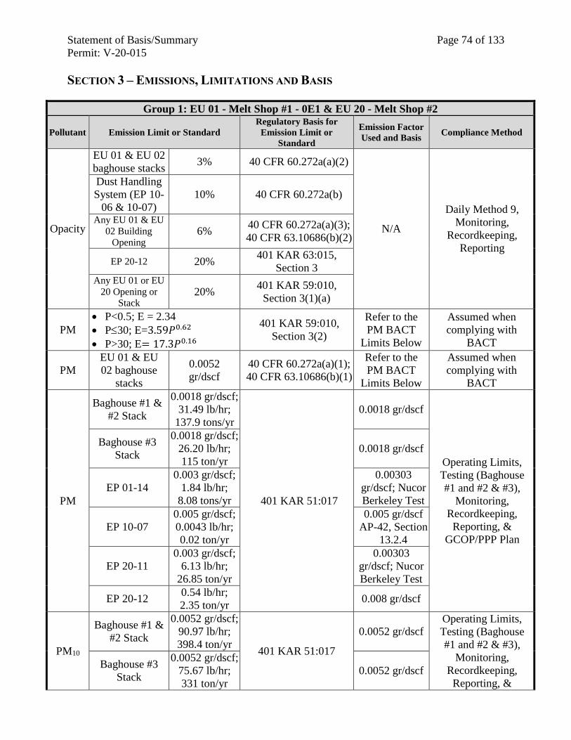
Statement of Basis/Summary Page 74 of 133
Permit: V-20-015
SECTION 3 – EMISSIONS, LIMITATIONS AND BASIS
Group 1: EU 01 - Melt Shop #1 - 0E1 & EU 20 - Melt Shop #2
Pollutant Emission Limit or Standard
Regulatory Basis for
Emission Limit or
Standard
Emission Factor
Used and Basis Compliance Method
Opacity
EU 01 & EU 02
baghouse stacks 3% 40 CFR 60.272a(a)(2)
N/A
Daily Method 9,
Monitoring,
Recordkeeping,
Reporting
Dust Handling
System (EP 10-
06 & 10-07)
10% 40 CFR 60.272a(b)
Any EU 01 & EU
02 Building
Opening 6%
40 CFR 60.272a(a)(3);
40 CFR 63.10686(b)(2)
EP 20-12 20% 401 KAR 63:015,
Section 3 Any EU 01 or EU
20 Opening or
Stack 20%
401 KAR 59:010,
Section 3(1)(a)
PM
P<0.5; E = 2.34
P30; E=3.59𝑃0.62
P>30; E= 17.3𝑃0.16
401 KAR 59:010,
Section 3(2)
Refer to the
PM BACT
Limits Below
Assumed when
complying with
BACT
PM
EU 01 & EU
02 baghouse
stacks
0.0052
gr/dscf
40 CFR 60.272a(a)(1);
40 CFR 63.10686(b)(1)
Refer to the
PM BACT
Limits Below
Assumed when
complying with
BACT
PM
Baghouse #1 &
#2 Stack
0.0018 gr/dscf;
31.49 lb/hr;
137.9 tons/yr
401 KAR 51:017
0.0018 gr/dscf
Operating Limits,
Testing (Baghouse
#1 and #2 & #3),
Monitoring,
Recordkeeping,
Reporting, &
GCOP/PPP Plan
Baghouse #3
Stack
0.0018 gr/dscf;
26.20 lb/hr;
115 ton/yr
0.0018 gr/dscf
EP 01-14
0.003 gr/dscf;
1.84 lb/hr;
8.08 tons/yr
0.00303
gr/dscf; Nucor
Berkeley Test
EP 10-07
0.005 gr/dscf;
0.0043 lb/hr;
0.02 ton/yr
0.005 gr/dscf
AP-42, Section
13.2.4
EP 20-11
0.003 gr/dscf;
6.13 lb/hr;
26.85 ton/yr
0.00303
gr/dscf; Nucor
Berkeley Test
EP 20-12 0.54 lb/hr;
2.35 ton/yr 0.008 gr/dscf
PM10
Baghouse #1 &
#2 Stack
0.0052 gr/dscf;
90.97 lb/hr;
398.4 ton/yr 401 KAR 51:017
0.0052 gr/dscf Operating Limits,
Testing (Baghouse
#1 and #2 & #3),
Monitoring,
Recordkeeping,
Reporting, &
Baghouse #3
Stack
0.0052 gr/dscf;
75.67 lb/hr;
331 ton/yr
0.0052 gr/dscf
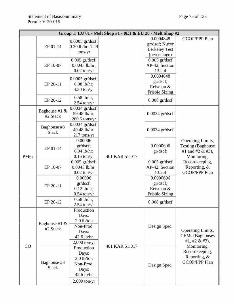
Statement of Basis/Summary Page 75 of 133
Permit: V-20-015
Group 1: EU 01 - Melt Shop #1 - 0E1 & EU 20 - Melt Shop #2
EP 01-14
0.0005 gr/dscf;
0.30 lb/hr; 1.29
tons/yr
0.0004848
gr/dscf; Nucor
Berkeley Test
(percentage)
GCOP/PPP Plan
EP 10-07
0.005 gr/dscf;
0.0043 lb/hr;
0.02 ton/yr
0.005 gr/dscf
AP-42, Section
13.2.4
EP 20-11
0.0005 gr/dscf;
0.98 lb/hr;
4.30 ton/yr
0.0004848
gr/dscf;
Reisman &
Frisbie Sizing
EP 20-12 0.58 lb/hr;
2.54 ton/yr 0.008 gr/dscf
PM2.5
Baghouse #1 &
#2 Stack
0.0034 gr/dscf;
59.48 lb/hr;
260.5 tons/yr
401 KAR 51:017
0.0034 gr/dscf
Operating Limits,
Testing (Baghouse
#1 and #2 & #3),
Monitoring,
Recordkeeping,
Reporting, &
GCOP/PPP Plan
Baghouse #3
Stack
0.0034 gr/dscf;
49.48 lb/hr;
217 tons/yr
0.0034 gr/dscf
EP 01-14
0.00006
gr/dscf;
0.04 lb/hr;
0.16 ton/yr
0.0000606
gr/dscf;
EP 10-07
0.005 gr/dscf;
0.0043 lb/hr;
0.02 ton/yr
0.005 gr/dscf
AP-42, Section
13.2.4
EP 20-11
0.00006
gr/dscf;
0.12 lb/hr;
0.54 ton/yr
0.0000606
gr/dscf;
Reisman &
Frisbie Sizing
EP 20-12 0.58 lb/hr;
2.54 ton/yr 0.008 gr/dscf
CO
Baghouse #1 &
#2 Stack
Production
Days:
2.0 lb/ton
401 KAR 51:017
Design Spec. Operating Limits,
CEMs (Baghouses
#1, #2 & #3),
Monitoring,
Recordkeeping,
Reporting, &
GCOP/PPP Plan
Non-Prod.
Days:
42.6 lb/hr
2,000 ton/yr
Baghouse #3
Stack
Production
Days:
2.0 lb/ton
Design Spec. Non-Prod.
Days:
42.6 lb/hr
2,000 ton/yr
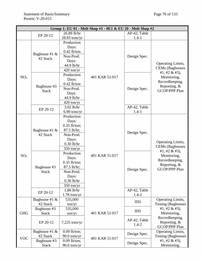
Statement of Basis/Summary Page 76 of 133
Permit: V-20-015
Group 1: EU 01 - Melt Shop #1 - 0E1 & EU 20 - Melt Shop #2
EP 20-12 26.89 lb/hr
28.83 tons/yr
AP-42, Table
1.4-1
NOx
Baghouse #1 &
#2 Stack
Production
Days:
0.42 lb/ton
401 KAR 51:017
Design Spec.
Operating Limits,
CEMs (Baghouses
#1, #2 & #3),
Monitoring,
Recordkeeping,
Reporting, &
GCOP/PPP Plan
Non-Prod.
Days:
44.9 lb/hr
420 ton/yr
Baghouse #3
Stack
Production
Days:
0.42 lb/ton
Design Spec. Non-Prod.
Days:
44.9 lb/hr
420 ton/yr
EP 20-12 3.02 lb/hr
6.90 tons/yr
AP-42, Table
1.4-1
SO2
Baghouse #1 &
#2 Stack
Production
Days:
0.35 lb/ton;
87.5 lb/hr;
401 KAR 51:017
Design Spec.
Operating Limits,
CEMs (Baghouses
#1, #2 & #3),
Monitoring,
Recordkeeping,
Reporting, &
GCOP/PPP Plan
Non-Prod.
Days:
0.30 lb/hr
350 ton/yr
Baghouse #3
Stack
Production
Days:
0.35 lb/ton;
87.5 lb/hr; Design Spec.
Non-Prod.
Days:
0.30 lb/hr
350 ton/yr
EP 20-12 1.86 lb/hr
1.78 tons/yr
AP-42, Table
1.4-2
GHG
Baghouse #1 &
#2 Stack
535,000
ton/yr
401 KAR 51:017
IISI Operating Limits,
Testing (Baghouses
#1, #2 & #3),
Monitoring,
Recordkeeping,
Reporting, &
GCOP/PPP Plan
Baghouse #3
Stack
535,000
ton/yr IISI
EP 20-12 7,225 tons/yr AP-42, Table
1.4-2
VOC
Baghouse #1 &
#2 Stack
0.09 lb/ton;
90.0 tons/yr 401 KAR 51:017
Design Spec. Operating Limits,
Testing (Baghouses
#1, #2 & #3),
Monitoring, Baghouse #3
Stack
0.09 lb/ton;
90.0 tons/yr Design Spec.
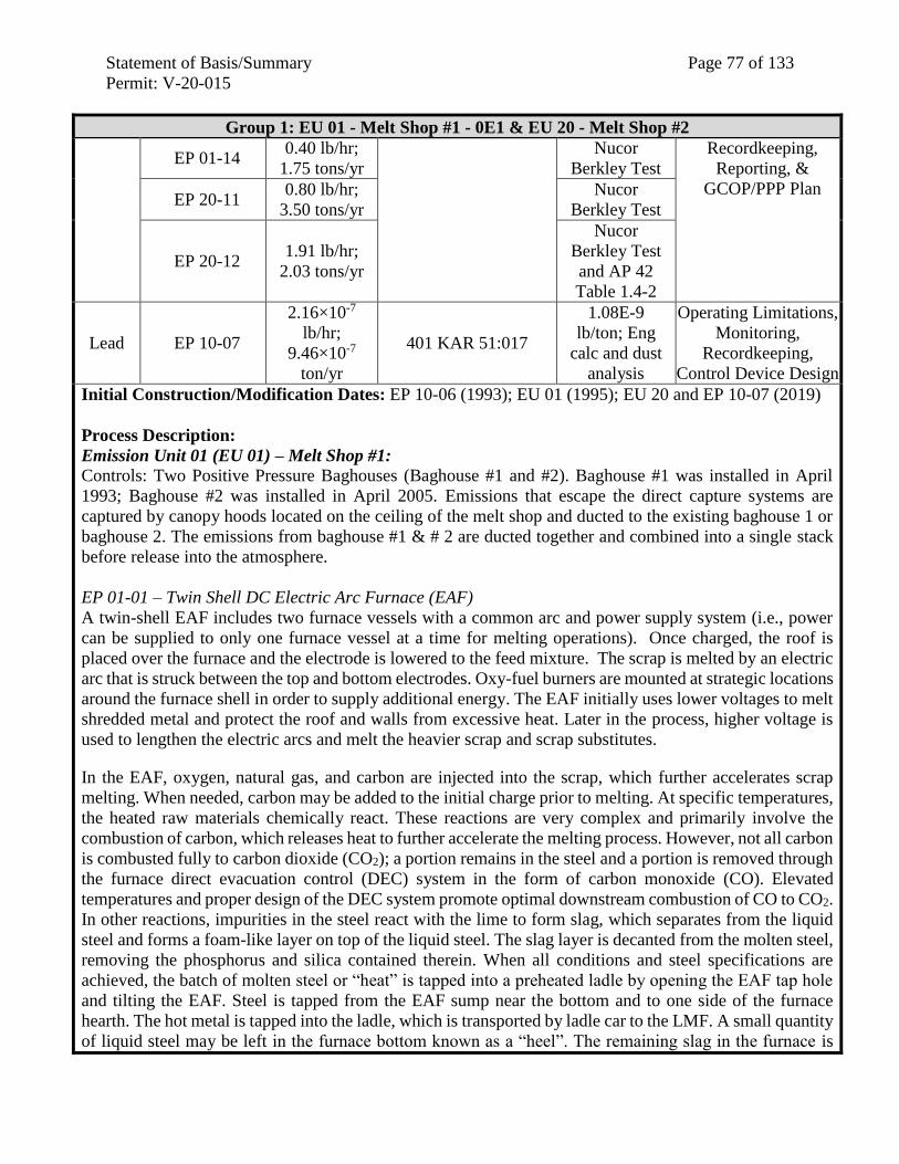
Statement of Basis/Summary Page 77 of 133
Permit: V-20-015
Group 1: EU 01 - Melt Shop #1 - 0E1 & EU 20 - Melt Shop #2
EP 01-14 0.40 lb/hr;
1.75 tons/yr
Nucor
Berkley Test
Recordkeeping,
Reporting, &
GCOP/PPP Plan EP 20-11
0.80 lb/hr;
3.50 tons/yr
Nucor
Berkley Test
EP 20-12 1.91 lb/hr;
2.03 tons/yr
Nucor
Berkley Test
and AP 42
Table 1.4-2
Lead EP 10-07
2.16×10⁻⁷
lb/hr;
9.46×10⁻⁷
ton/yr
401 KAR 51:017
1.08E-9
lb/ton; Eng
calc and dust
analysis
Operating Limitations,
Monitoring,
Recordkeeping,
Control Device Design
Initial Construction/Modification Dates: EP 10-06 (1993); EU 01 (1995); EU 20 and EP 10-07 (2019)
Process Description:
Emission Unit 01 (EU 01) – Melt Shop #1: Controls: Two Positive Pressure Baghouses (Baghouse #1 and #2). Baghouse #1 was installed in April
1993; Baghouse #2 was installed in April 2005. Emissions that escape the direct capture systems are
captured by canopy hoods located on the ceiling of the melt shop and ducted to the existing baghouse 1 or
baghouse 2. The emissions from baghouse #1 & # 2 are ducted together and combined into a single stack
before release into the atmosphere.
EP 01-01 – Twin Shell DC Electric Arc Furnace (EAF)
A twin-shell EAF includes two furnace vessels with a common arc and power supply system (i.e., power
can be supplied to only one furnace vessel at a time for melting operations). Once charged, the roof is
placed over the furnace and the electrode is lowered to the feed mixture. The scrap is melted by an electric
arc that is struck between the top and bottom electrodes. Oxy-fuel burners are mounted at strategic locations
around the furnace shell in order to supply additional energy. The EAF initially uses lower voltages to melt
shredded metal and protect the roof and walls from excessive heat. Later in the process, higher voltage is
used to lengthen the electric arcs and melt the heavier scrap and scrap substitutes.
In the EAF, oxygen, natural gas, and carbon are injected into the scrap, which further accelerates scrap
melting. When needed, carbon may be added to the initial charge prior to melting. At specific temperatures,
the heated raw materials chemically react. These reactions are very complex and primarily involve the
combustion of carbon, which releases heat to further accelerate the melting process. However, not all carbon
is combusted fully to carbon dioxide (CO2); a portion remains in the steel and a portion is removed through
the furnace direct evacuation control (DEC) system in the form of carbon monoxide (CO). Elevated
temperatures and proper design of the DEC system promote optimal downstream combustion of CO to CO2.
In other reactions, impurities in the steel react with the lime to form slag, which separates from the liquid
steel and forms a foam-like layer on top of the liquid steel. The slag layer is decanted from the molten steel,
removing the phosphorus and silica contained therein. When all conditions and steel specifications are
achieved, the batch of molten steel or “heat” is tapped into a preheated ladle by opening the EAF tap hole
and tilting the EAF. Steel is tapped from the EAF sump near the bottom and to one side of the furnace
hearth. The hot metal is tapped into the ladle, which is transported by ladle car to the LMF. A small quantity
of liquid steel may be left in the furnace bottom known as a “heel”. The remaining slag in the furnace is
Statement of Basis/Summary Page 78 of 133
Permit: V-20-015
Group 1: EU 01 - Melt Shop #1 - 0E1 & EU 20 - Melt Shop #2
drained out the slag door, located on the front of the furnace, into a slag pot that is transported to a separate
slag processor via Kress carrier.
The EAF is equipped with a DEC system that captures and vents emissions generated during the melting
and refining processes to two positive pressure baghouses (#1 & #2). Emissions that escape the DEC system
or are generated during charging and tapping are captured by canopy hoods strategically located on the
ceiling of the melt shop. The canopy hoods vent emissions to the Melt Shop Baghouse for control of
particle-phase pollutants. Small quantities of emissions escape the melt shop (1%), primarily through the
scrap charge bay door, as melt shop fugitives.
Six (6) oxy-fuel fired burners are mounted at strategic locations around the EAF shell to supply additional
energy to the heat. These include four (4) sidewall burners each with a heat capacity of 18 MMBtu/hr, one
(1) door burner with a heat capacity of 15 MMBtu/hr, and one (1) sump burner with a heat capacity of 10
MMBtu/hr.
Maximum Capacity: 250 ton steel/hr; 500 lb fluorspar/heat; 2,000,000 ton/yr
Burner Maximum Capacity: 97 MMBtu/hr
Control Device: Baghouse #1
EP 01-02 – Continuous Caster (A-Line)
In the casting unit, liquid steel is poured from the ladle into a tundish, which meters the molten steel into a
vertical, water-cooled, copper mold that is the desired width and thickness of the resulting slab. The tundish
is a refractory-lined, elongated trough that has a drain sized for the slab caster. From the mold, the steel
then moves down through the water-spray cooling chamber via rollers and begins solidifying on the outside.
Emissions generated during the casting process are captured by canopy hoods and vented to the Melt Shop
Baghouse #1
Maximum Capacity: 250 ton steel/hr; 2,000,000 ton/yr
Control Device: Baghouse #1
EP 01-03 A & B - Ladle Metallurgical Furnaces (LMF)-(2)
From the EAF, the ladles of molten steel are transferred to the LMF where final steel refining takes place.
At the LMF, the molten bath is first sampled to determine the existing chemistry. The chemistry is then
adjusted by additions of various materials such as carbon, lime, and alloys. After reaching the appropriate
chemistry, the bath temperature is elevated above the melting point of steel to prevent the steel from
solidifying prior to reaching the vacuum degasser or caster.
The LMF is equipped with a direct capture system (e.g., side draft hoods) that captures and vents emissions
to the Melt Shop Baghouse #2. Emissions that escape the LMF capture system are captured by canopy
hoods and ducted to the Melt Shop Baghouse (#1 or #2) for control of particle-phase pollutants. Oxygen
will be removed from the steel in the LMF through addition of aluminum and silicon. This deoxidation
process removes dissolved oxygen in the melt, and minimizes the potential for natural decarburization
during the vacuum degassing processes.
Maximum Capacity: 250 ton steel/hr; 2,000,000 ton/yr
Control Device: Baghouse (C0101)
Statement of Basis/Summary Page 79 of 133
Permit: V-20-015
Group 1: EU 01 - Melt Shop #1 - 0E1 & EU 20 - Melt Shop #2
EP 01-04 A, B, C, & D – Ladle Pre-Heaters-(4)
Four (4) ladle preheaters. Emissions from natural gas combustion are discharged into the melt shop and
captures by the canopy hoods that are ducted to the Melt Shop Baghouse for PM control.
Burner Maximum Capacity: four at 10 MMBtu/hr, each
Control Device: Baghouse #2
EP 01-05 – Ladle Dryer
One (1) ladle dryer. The ladle drying station is equipped with a direct capture system to capture and duct
the natural gas combustion emissions and any nuisance odors generated from drying the ladle refractory to
the Melt Shop Baghouse.
Burner Maximum Capacity: 10 MMBtu/hr
Control Device: Baghouse #1
EP 01-06 A & B – Tundish Preheaters (2)
Two (2) tundish preheaters. Emissions from natural gas combustion are discharged into the melt shop and
captured by the canopy hoods that are ducted to the Melt Shop Baghouse for PM control.
Burner Maximum Capacity: 8 MMBtu/hr, each
Control Device: Baghouse #1
EP 01-07 A & B – Tundish Side Preheaters (2) & SEN Preheaters (2)
Two (2) tundish side preheaters and two (2) submerged entry nozzle (SEN) preheaters. Emissions from
natural gas combustion are discharged into the melt shop and captured by canopy hoods that are ducted to
the Melt Shop Baghouse for PM control.
Burner Maximum Capacity: 1.1 MMBtu/hr, each
Control Device: Baghouse #1
EP 01-08 – Tundish Dryers (2) & Mandrel Preheaters (2)
two (2) tundish dryers, and two (2) mandrel preheaters. Emissions from natural gas combustion are
discharged into the melt shop and captured by the canopy hoods that are ducted to the Melt Shop Baghouse
for PM control.
Burner Maximum Capacity: 1.0 MMBtu/hr, each
Control Device: Baghouse #1
EP 01-09 – Tundish Preparation
Tundish preparation activities occur in the melt shop and are conducted as needed. These operations include
removal of used refractory in the tundish dump station, repair of the tundish refractory by rebricking with
new refractory, and deskulling the tundishes of accumulated residual metal. The tundish dump station has
a dedicated hood to capture emissions generated during the removal of used refractory, which is vented to
the Melt Shop Baghouse. Tundish repair results in both particulate emissions and VOC emissions from the
refractory resin. Tundish deskull uses nine natural gas fueled torches to cut up the skulls from the tundish.
Maximum Capacity: 7.1 tons/hr; 62,196 tons/yr
Control Device: Baghouses #1 & #2
EP 01-10 – Ladle Preparation
Ladle preparation activities, including ladle dump and ladle repair, occur in the melt shop where potential
particulate emissions generated during refractory preparation and repair are captured by the local canopy
hoods for control at the Melt Shop Baghouse.
Statement of Basis/Summary Page 80 of 133
Permit: V-20-015
Group 1: EU 01 - Melt Shop #1 - 0E1 & EU 20 - Melt Shop #2
Maximum Capacity: 42 tons/hr; 367,920 tons/yr
Control Device: Baghouses #1 & #2
EP 01-11 – Used Refractory Cleanout
Furnace refractory cleanout, using pneumatic and manual tools, occurs in the melt shop where potential
particulate emissions released within the melt shop are captured by the local canopy hoods for control at
the Melt Shop Baghouse.
Maximum Capacity: 72 tons refractory/hr; 630,720 tons/yr
Control Device: Baghouses #1 & #2
EP 01-12 A & B – Stirring Stations (4)
Raw materials are added and mixed by argon gas bubbling practices at the Stirring Stations and then moved
to the LMF for refining; emissions from the stirring stations are captured by the ladle car capture system
and vented to the Melt Shop Baghouse for PM control
Maximum Capacity: 250 tons/hr; 2,000,000 tons/yr
Control Device: Baghouse #2
EP 01-13 – Scrap Cutting from Slag Pot
Scrap cutting activities occur in the melt shop and are conducted as needed. The capture emissions generated
during the removal of scrap is vented to the Melt Shop Baghouse.
Maximum Capacity: 2.0 tons/hr; 3,822 tons/yr
Control Device: Baghouses #1 & #2
EP 01-14 – A-Line Caster Spray Vent
Steam formed from the contact of cooling water with the hot steel is captured and vented through caster
spray vents that discharge above the roof of the Melt Shop.
Maximum Capacity: 250 tons steel/hr; 2,000,000 tons/yr
Control Device: None
EP 10–06 – Melt Shop #1 Baghouse #1 & #2 Dust Silo & Railcar Loading
Dust collected in the Melt Shop Baghouses is conveyed via an enclosed conveyor system to a silo for
temporary storage. The baghouse dust is pneumatically loaded from the silo to the rail car.
Maximum Capacity: 5 ton dust/hr; 35,000 ton/yr
Control Device: Dust Collector/Enclosure
EP 10–07 – Melt Shop #2 Baghouse #3 Dust Silo & Railcar Loading
Dust collected in the Melt Shop Baghouse is conveyed via an enclosed conveyor system to a silo for
temporary storage. The baghouse dust is pneumatically loaded from the silo to the rail car.
Maximum Capacity: 5 ton dust/hr; 35,000 ton/yr
Control Device: Dust Collector/Passive Bin Vent Filter
Statement of Basis/Summary Page 81 of 133
Permit: V-20-015
Group 1: EU 01 - Melt Shop #1 - 0E1 & EU 20 - Melt Shop #2
Emission Unit 20 (EU 20) – Melt Shop #2: Process Description:
Emission Unit 20 (EU 20) – Melt Shop #2:
Controls: Negative Pressure Baghouse #3. The Melt Shop is equipped with canopy hoods to capture and
vent emissions that are not captured by the direct shell evacuation system (DEC or DSE). The melt shop
has an overall capture efficiency of 99% of emissions generated within the melt shop.
EP 20-01 – Single Shell DC Electric Arc Furnace (EAF)
Single-shell DC Electric Arc Furnace (EAF) that has a larger melting capacity than the existing duel shell
EAFs combined (EP 01-01). Operation of the single shell DC EAF is similar to the twin shell DC EAF in
that feed material drops from an overhead scrap bucket into the shell, the furnace roof swings back into
place, and an electrode lowers into the scrap to start the melting process. As with the duel-shell EAF, the
single-shell EAF is equipped with a DEC system to capture and vent emissions, generated by melting and
refining, to Baghouse # 3.
Five (5) oxy-fuel fired burners are mounted at strategic locations around the EAF shell to supply additional
energy to the heat. These include four (4) sidewall burners each with a heat capacity of 17.1 MMBtu/hr,
and one (1) sump burner with a heat capacity of 17.1 MMBtu/hr.
Maximum Capacity: 250 ton steel/hr; 500 lb fluorspar/heat; 2,000,000 ton/yr
Burner Maximum Capacity: 85.5 MMBtu/hr
Control Device: Baghouse #3
EP 20-02 A & B - Ladle Metallurgical Furnaces (LMF)-(2)
From the EAF, the ladles of molten steel are transferred to the LMF where final steel refining takes place.
At the LMF, the molten bath is first sampled to determine the existing chemistry. The chemistry is then
adjusted by additions of various materials such as carbon, lime, and alloys. After reaching the appropriate
chemistry, the bath temperature is elevated above the melting point of steel to prevent the steel from
solidifying prior to reaching the vacuum degasser or caster.
The LMF is equipped with a direct capture system (e.g., side draft hoods) that captures and vents emissions
to the Melt Shop Baghouse #3. Canopy hoods, located overhead at the roofline, catch emissions not captured
by the DEC system, venting these emissions to Baghouse #3 for control of particle-phase pollutants. Oxygen
will be removed from the steel in the LMF through addition of aluminum and silicon. This deoxidation
process removes dissolved oxygen in the melt, and minimizes the potential for natural decarburization
during the vacuum degassing processes.
Maximum Capacity: 250 ton steel/hr; 2,000,000 ton/yr
Control Device: Baghouse #3
EP 20-03 – Continuous Caster B-Line
In the casting unit, liquid steel is poured from the ladle into a tundish, which meters the molten steel into a
vertical, water-cooled, copper mold that is the desired width and thickness of the resulting slab. The tundish
is a refractory-lined, elongated trough that has a drain sized for the slab caster. From the mold, the steel
then moves down through the water-spray cooling chamber via rollers and begins solidifying on the outside.
In order to maintain a continuous casting process, ladles of molten steel are staged to provide enough buffer
for the desired period of continuous casting. This staging process results in a greater short-term maximum
capacity of the continuous caster (500 ton/hr) than the EAF, LMF, and vacuum degasser (250 ton/hr).
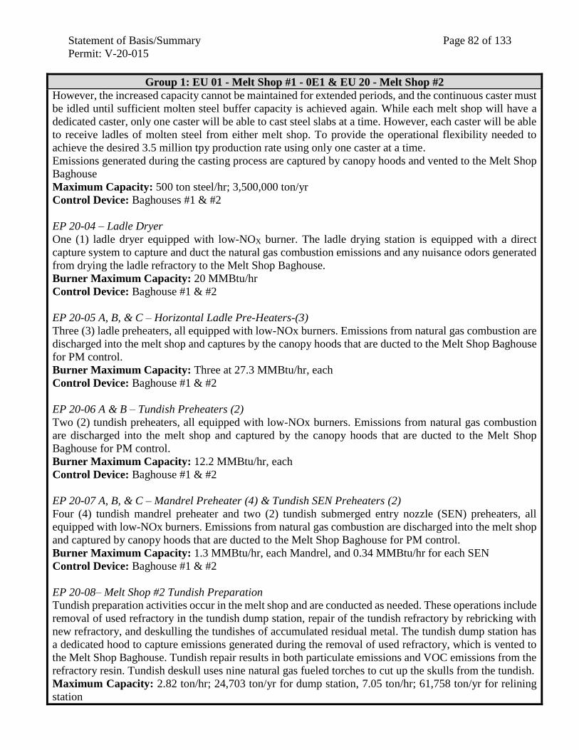
Statement of Basis/Summary Page 82 of 133
Permit: V-20-015
Group 1: EU 01 - Melt Shop #1 - 0E1 & EU 20 - Melt Shop #2
However, the increased capacity cannot be maintained for extended periods, and the continuous caster must
be idled until sufficient molten steel buffer capacity is achieved again. While each melt shop will have a
dedicated caster, only one caster will be able to cast steel slabs at a time. However, each caster will be able
to receive ladles of molten steel from either melt shop. To provide the operational flexibility needed to
achieve the desired 3.5 million tpy production rate using only one caster at a time.
Emissions generated during the casting process are captured by canopy hoods and vented to the Melt Shop
Baghouse
Maximum Capacity: 500 ton steel/hr; 3,500,000 ton/yr
Control Device: Baghouses #1 & #2
EP 20-04 – Ladle Dryer
One (1) ladle dryer equipped with low-NOX burner. The ladle drying station is equipped with a direct
capture system to capture and duct the natural gas combustion emissions and any nuisance odors generated
from drying the ladle refractory to the Melt Shop Baghouse.
Burner Maximum Capacity: 20 MMBtu/hr
Control Device: Baghouse #1 & #2
EP 20-05 A, B, & C – Horizontal Ladle Pre-Heaters-(3)
Three (3) ladle preheaters, all equipped with low-NOx burners. Emissions from natural gas combustion are
discharged into the melt shop and captures by the canopy hoods that are ducted to the Melt Shop Baghouse
for PM control.
Burner Maximum Capacity: Three at 27.3 MMBtu/hr, each
Control Device: Baghouse #1 & #2
EP 20-06 A & B – Tundish Preheaters (2)
Two (2) tundish preheaters, all equipped with low-NOx burners. Emissions from natural gas combustion
are discharged into the melt shop and captured by the canopy hoods that are ducted to the Melt Shop
Baghouse for PM control.
Burner Maximum Capacity: 12.2 MMBtu/hr, each
Control Device: Baghouse #1 & #2
EP 20-07 A, B, & C – Mandrel Preheater (4) & Tundish SEN Preheaters (2)
Four (4) tundish mandrel preheater and two (2) tundish submerged entry nozzle (SEN) preheaters, all
equipped with low-NOx burners. Emissions from natural gas combustion are discharged into the melt shop
and captured by canopy hoods that are ducted to the Melt Shop Baghouse for PM control.
Burner Maximum Capacity: 1.3 MMBtu/hr, each Mandrel, and 0.34 MMBtu/hr for each SEN
Control Device: Baghouse #1 & #2
EP 20-08– Melt Shop #2 Tundish Preparation
Tundish preparation activities occur in the melt shop and are conducted as needed. These operations include
removal of used refractory in the tundish dump station, repair of the tundish refractory by rebricking with
new refractory, and deskulling the tundishes of accumulated residual metal. The tundish dump station has
a dedicated hood to capture emissions generated during the removal of used refractory, which is vented to
the Melt Shop Baghouse. Tundish repair results in both particulate emissions and VOC emissions from the
refractory resin. Tundish deskull uses nine natural gas fueled torches to cut up the skulls from the tundish.
Maximum Capacity: 2.82 ton/hr; 24,703 ton/yr for dump station, 7.05 ton/hr; 61,758 ton/yr for relining
station
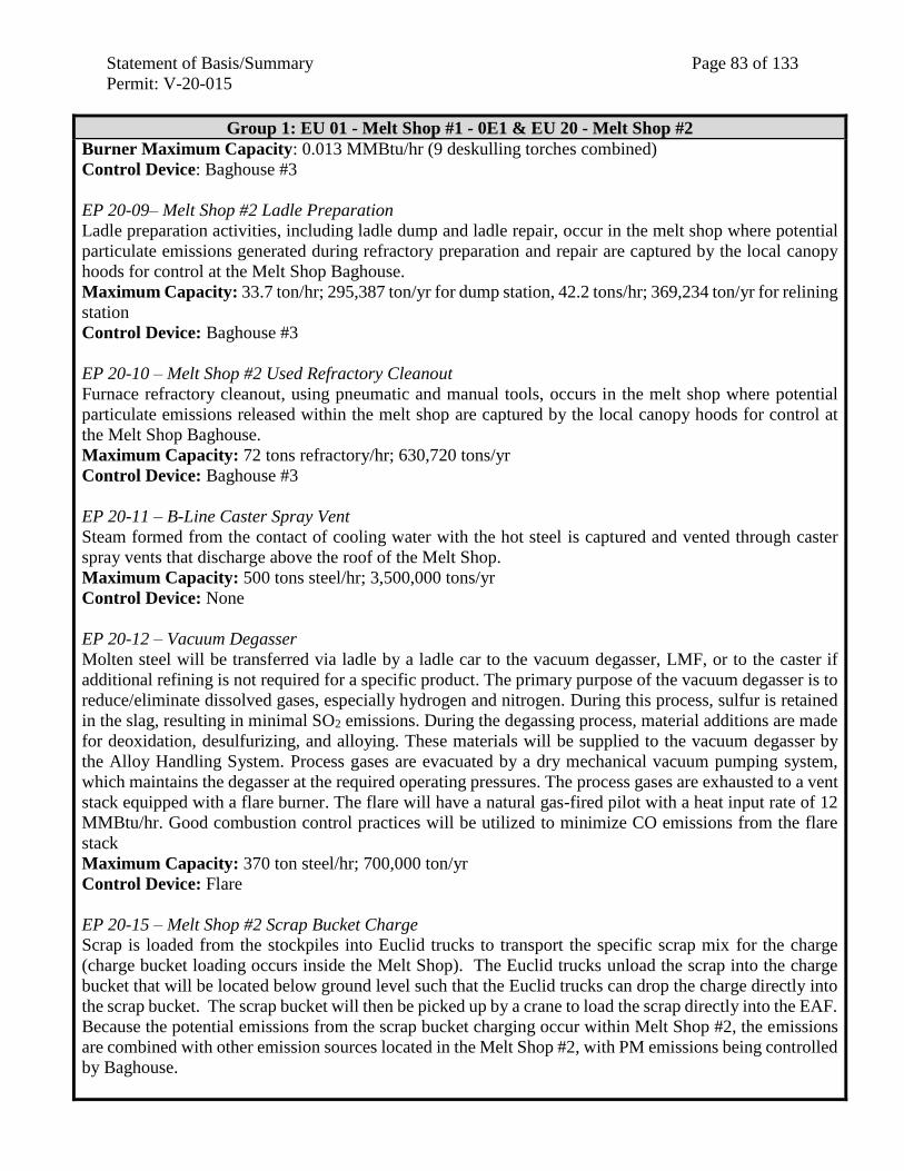
Statement of Basis/Summary Page 83 of 133
Permit: V-20-015
Group 1: EU 01 - Melt Shop #1 - 0E1 & EU 20 - Melt Shop #2
Burner Maximum Capacity: 0.013 MMBtu/hr (9 deskulling torches combined)
Control Device: Baghouse #3
EP 20-09– Melt Shop #2 Ladle Preparation
Ladle preparation activities, including ladle dump and ladle repair, occur in the melt shop where potential
particulate emissions generated during refractory preparation and repair are captured by the local canopy
hoods for control at the Melt Shop Baghouse.
Maximum Capacity: 33.7 ton/hr; 295,387 ton/yr for dump station, 42.2 tons/hr; 369,234 ton/yr for relining
station
Control Device: Baghouse #3
EP 20-10 – Melt Shop #2 Used Refractory Cleanout
Furnace refractory cleanout, using pneumatic and manual tools, occurs in the melt shop where potential
particulate emissions released within the melt shop are captured by the local canopy hoods for control at
the Melt Shop Baghouse.
Maximum Capacity: 72 tons refractory/hr; 630,720 tons/yr
Control Device: Baghouse #3
EP 20-11 – B-Line Caster Spray Vent
Steam formed from the contact of cooling water with the hot steel is captured and vented through caster
spray vents that discharge above the roof of the Melt Shop.
Maximum Capacity: 500 tons steel/hr; 3,500,000 tons/yr
Control Device: None
EP 20-12 – Vacuum Degasser
Molten steel will be transferred via ladle by a ladle car to the vacuum degasser, LMF, or to the caster if
additional refining is not required for a specific product. The primary purpose of the vacuum degasser is to
reduce/eliminate dissolved gases, especially hydrogen and nitrogen. During this process, sulfur is retained
in the slag, resulting in minimal SO2 emissions. During the degassing process, material additions are made
for deoxidation, desulfurizing, and alloying. These materials will be supplied to the vacuum degasser by
the Alloy Handling System. Process gases are evacuated by a dry mechanical vacuum pumping system,
which maintains the degasser at the required operating pressures. The process gases are exhausted to a vent
stack equipped with a flare burner. The flare will have a natural gas-fired pilot with a heat input rate of 12
MMBtu/hr. Good combustion control practices will be utilized to minimize CO emissions from the flare
stack
Maximum Capacity: 370 ton steel/hr; 700,000 ton/yr
Control Device: Flare
EP 20-15 – Melt Shop #2 Scrap Bucket Charge
Scrap is loaded from the stockpiles into Euclid trucks to transport the specific scrap mix for the charge
(charge bucket loading occurs inside the Melt Shop). The Euclid trucks unload the scrap into the charge
bucket that will be located below ground level such that the Euclid trucks can drop the charge directly into
the scrap bucket. The scrap bucket will then be picked up by a crane to load the scrap directly into the EAF.
Because the potential emissions from the scrap bucket charging occur within Melt Shop #2, the emissions
are combined with other emission sources located in the Melt Shop #2, with PM emissions being controlled
by Baghouse.
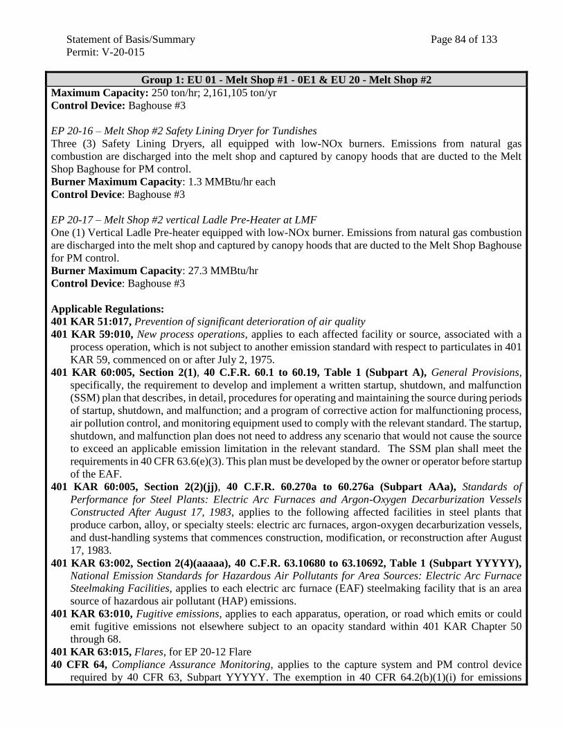
Statement of Basis/Summary Page 84 of 133
Permit: V-20-015
Group 1: EU 01 - Melt Shop #1 - 0E1 & EU 20 - Melt Shop #2
Maximum Capacity: 250 ton/hr; 2,161,105 ton/yr
Control Device: Baghouse #3
EP 20-16 – Melt Shop #2 Safety Lining Dryer for Tundishes
Three (3) Safety Lining Dryers, all equipped with low-NOx burners. Emissions from natural gas
combustion are discharged into the melt shop and captured by canopy hoods that are ducted to the Melt
Shop Baghouse for PM control.
Burner Maximum Capacity: 1.3 MMBtu/hr each
Control Device: Baghouse #3
EP 20-17 – Melt Shop #2 vertical Ladle Pre-Heater at LMF
One (1) Vertical Ladle Pre-heater equipped with low-NOx burner. Emissions from natural gas combustion
are discharged into the melt shop and captured by canopy hoods that are ducted to the Melt Shop Baghouse
for PM control.
Burner Maximum Capacity: 27.3 MMBtu/hr
Control Device: Baghouse #3
Applicable Regulations:
401 KAR 51:017, Prevention of significant deterioration of air quality
401 KAR 59:010, New process operations, applies to each affected facility or source, associated with a
process operation, which is not subject to another emission standard with respect to particulates in 401
KAR 59, commenced on or after July 2, 1975.
401 KAR 60:005, Section 2(1), 40 C.F.R. 60.1 to 60.19, Table 1 (Subpart A), General Provisions,
specifically, the requirement to develop and implement a written startup, shutdown, and malfunction
(SSM) plan that describes, in detail, procedures for operating and maintaining the source during periods
of startup, shutdown, and malfunction; and a program of corrective action for malfunctioning process,
air pollution control, and monitoring equipment used to comply with the relevant standard. The startup,
shutdown, and malfunction plan does not need to address any scenario that would not cause the source
to exceed an applicable emission limitation in the relevant standard. The SSM plan shall meet the
requirements in 40 CFR 63.6(e)(3). This plan must be developed by the owner or operator before startup
of the EAF.
401 KAR 60:005, Section 2(2)(jj), 40 C.F.R. 60.270a to 60.276a (Subpart AAa), Standards of
Performance for Steel Plants: Electric Arc Furnaces and Argon-Oxygen Decarburization Vessels
Constructed After August 17, 1983, applies to the following affected facilities in steel plants that
produce carbon, alloy, or specialty steels: electric arc furnaces, argon-oxygen decarburization vessels,
and dust-handling systems that commences construction, modification, or reconstruction after August
17, 1983.
401 KAR 63:002, Section 2(4)(aaaaa), 40 C.F.R. 63.10680 to 63.10692, Table 1 (Subpart YYYYY),
National Emission Standards for Hazardous Air Pollutants for Area Sources: Electric Arc Furnace
Steelmaking Facilities, applies to each electric arc furnace (EAF) steelmaking facility that is an area
source of hazardous air pollutant (HAP) emissions.
401 KAR 63:010, Fugitive emissions, applies to each apparatus, operation, or road which emits or could
emit fugitive emissions not elsewhere subject to an opacity standard within 401 KAR Chapter 50
through 68.
401 KAR 63:015, Flares, for EP 20-12 Flare
40 CFR 64, Compliance Assurance Monitoring, applies to the capture system and PM control device
required by 40 CFR 63, Subpart YYYYY. The exemption in 40 CFR 64.2(b)(1)(i) for emissions
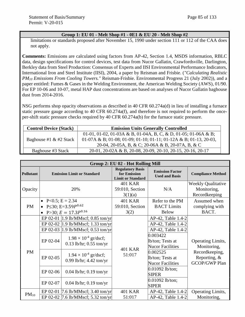
Statement of Basis/Summary Page 85 of 133
Permit: V-20-015
Group 1: EU 01 - Melt Shop #1 - 0E1 & EU 20 - Melt Shop #2
limitations or standards proposed after November 15, 1990 under section 111 or 112 of the CAA does
not apply.
Comments: Emissions are calculated using factors from AP-42, Section 1.4, MSDS information, RBLC
data, design specifications for control devices, test data from Nucor Gallatin, Crawfordsville, Darlington,
Berkley data from Steel Production: Consensus of Experts and IISI Environmental Performance Indicators,
International Iron and Steel Institute (IISI), 2004, a paper by Reisman and Frisbie. ("Calculating Realistic
PM10 Emissions From Cooling Towers." Reisman-Frisbie. Environmental Progress 21 (July 2002)), and a
paper entitled: Fumes & Gases in the Welding Environment, the American Welding Society (AWS), 01/90.
For EP 10-06 and 10-07, metal HAP dust concentrations are based on analyses of Nucor Gallatin baghouse
dust from 2014-2016.
NSG performs shop opacity observations as described in 40 CFR 60.274a(d) in lieu of installing a furnace
static pressure gauge according to 40 CFR 60.274a(f), and therefore is not required to perform the once-
per-shift static pressure checks required by 40 CFR 60.274a(b) for the furnace static pressure.
Control Device (Stack) Emission Units Generally Controlled
Baghouse #1 & #2 Stack
01-01, 01-02, 01-03A & B, 01-04A, B, C, & D, 01-05; 01-06A & B;
01-07A & B; 01-08; 01-09; 01-10; 01-11; 01-12A & B; 01-13, 20-03,
20-04, 20-05A, B, & C; 20-06A & B, 20-07A, B, & C
Baghouse #3 Stack 20-01, 20-02A & B, 20-08, 20-09, 20-10, 20-15, 20-16, 20-17
Group 2: EU 02 - Hot Rolling Mill
Pollutant Emission Limit or Standard
Regulatory Basis
for Emission
Limit or Standard
Emission Factor
Used and Basis Compliance Method
Opacity 20%
401 KAR
59:010, Section
3(1)(a)
N/A
Weekly Qualitative
Monitoring,
Recordkeeping
PM
P<0.5; E = 2.34
P30; E=3.59𝑃0.62
P>30; 𝐸 = 17.3𝑃0.16
401 KAR
59:010, Section
3(2)
Refer to the PM
BACT Limits
Below
Assumed when
complying with
BACT.
PM
EP 02-01 1.9 lb/MMscf; 0.85 ton/yr
401 KAR
51:017
AP-42, Table 1.4-2
Operating Limits,
Monitoring,
Recordkeeping,
Reporting, &
GCOP/GWP Plan
EP 02-02 1.9 lb/MMscf; 1.33 ton/yr AP-42, Table 1.4-2
EP 02-03 1.9 lb/MMscf; 0.53 ton/yr AP-42, Table 1.4-2
EP 02-04 1.98 × 10⁻⁴ gr/dscf;
0.13 lb/hr; 0.55 ton/yr
0.003422
lb/ton; Tests at
Nucor Facilities
EP 02-05 1.94 × 10⁻⁴ gr/dscf;
0.99 lb/hr; 4.42 ton/yr
0.002525
lb/ton; Tests at
Nucor Facilities
EP 02-06 0.04 lb/hr; 0.19 ton/yr 0.01092 lb/ton;
SIPER
EP 02-07 0.04 lb/hr; 0.19 ton/yr 0.01092 lb/ton;
SIPER
PM10 EP 02-01 7.6 lb/MMscf; 3.40 ton/yr 401 KAR
51:017
AP-42, Table 1.4-2 Operating Limits,
Monitoring, EP 02-02 7.6 lb/MMscf; 5.32 ton/yr AP-42, Table 1.4-2
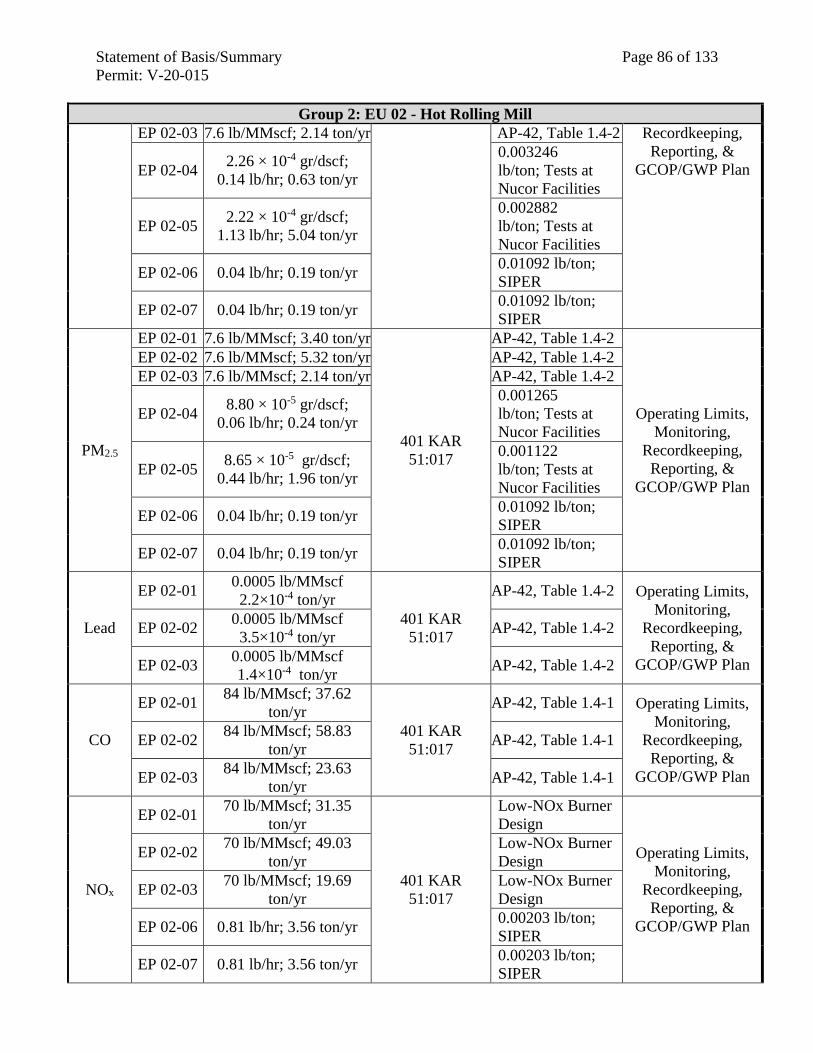
Statement of Basis/Summary Page 86 of 133
Permit: V-20-015
Group 2: EU 02 - Hot Rolling Mill
EP 02-03 7.6 lb/MMscf; 2.14 ton/yr AP-42, Table 1.4-2 Recordkeeping,
Reporting, &
GCOP/GWP Plan EP 02-04 2.26 × 10⁻⁴ gr/dscf;
0.14 lb/hr; 0.63 ton/yr
0.003246
lb/ton; Tests at
Nucor Facilities
EP 02-05 2.22 × 10⁻⁴ gr/dscf;
1.13 lb/hr; 5.04 ton/yr
0.002882
lb/ton; Tests at
Nucor Facilities
EP 02-06 0.04 lb/hr; 0.19 ton/yr 0.01092 lb/ton;
SIPER
EP 02-07 0.04 lb/hr; 0.19 ton/yr 0.01092 lb/ton;
SIPER
PM2.5
EP 02-01 7.6 lb/MMscf; 3.40 ton/yr
401 KAR
51:017
AP-42, Table 1.4-2
Operating Limits,
Monitoring,
Recordkeeping,
Reporting, &
GCOP/GWP Plan
EP 02-02 7.6 lb/MMscf; 5.32 ton/yr AP-42, Table 1.4-2
EP 02-03 7.6 lb/MMscf; 2.14 ton/yr AP-42, Table 1.4-2
EP 02-04 8.80 × 10⁻⁵ gr/dscf;
0.06 lb/hr; 0.24 ton/yr
0.001265
lb/ton; Tests at
Nucor Facilities
EP 02-05 8.65 × 10⁻⁵ gr/dscf;
0.44 lb/hr; 1.96 ton/yr
0.001122
lb/ton; Tests at
Nucor Facilities
EP 02-06 0.04 lb/hr; 0.19 ton/yr 0.01092 lb/ton;
SIPER
EP 02-07 0.04 lb/hr; 0.19 ton/yr 0.01092 lb/ton;
SIPER
Lead
EP 02-01 0.0005 lb/MMscf
2.2×10⁻⁴ ton/yr
401 KAR
51:017
AP-42, Table 1.4-2 Operating Limits,
Monitoring,
Recordkeeping,
Reporting, &
GCOP/GWP Plan
EP 02-02 0.0005 lb/MMscf
3.5×10⁻⁴ ton/yr AP-42, Table 1.4-2
EP 02-03 0.0005 lb/MMscf
1.4×10⁻⁴ ton/yr AP-42, Table 1.4-2
CO
EP 02-01 84 lb/MMscf; 37.62
ton/yr
401 KAR
51:017
AP-42, Table 1.4-1 Operating Limits,
Monitoring,
Recordkeeping,
Reporting, &
GCOP/GWP Plan
EP 02-02 84 lb/MMscf; 58.83
ton/yr AP-42, Table 1.4-1
EP 02-03 84 lb/MMscf; 23.63
ton/yr AP-42, Table 1.4-1
NOx
EP 02-01 70 lb/MMscf; 31.35
ton/yr
401 KAR
51:017
Low-NOx Burner
Design
Operating Limits,
Monitoring,
Recordkeeping,
Reporting, &
GCOP/GWP Plan
EP 02-02 70 lb/MMscf; 49.03
ton/yr
Low-NOx Burner
Design
EP 02-03 70 lb/MMscf; 19.69
ton/yr
Low-NOx Burner
Design
EP 02-06 0.81 lb/hr; 3.56 ton/yr 0.00203 lb/ton;
SIPER
EP 02-07 0.81 lb/hr; 3.56 ton/yr 0.00203 lb/ton;
SIPER
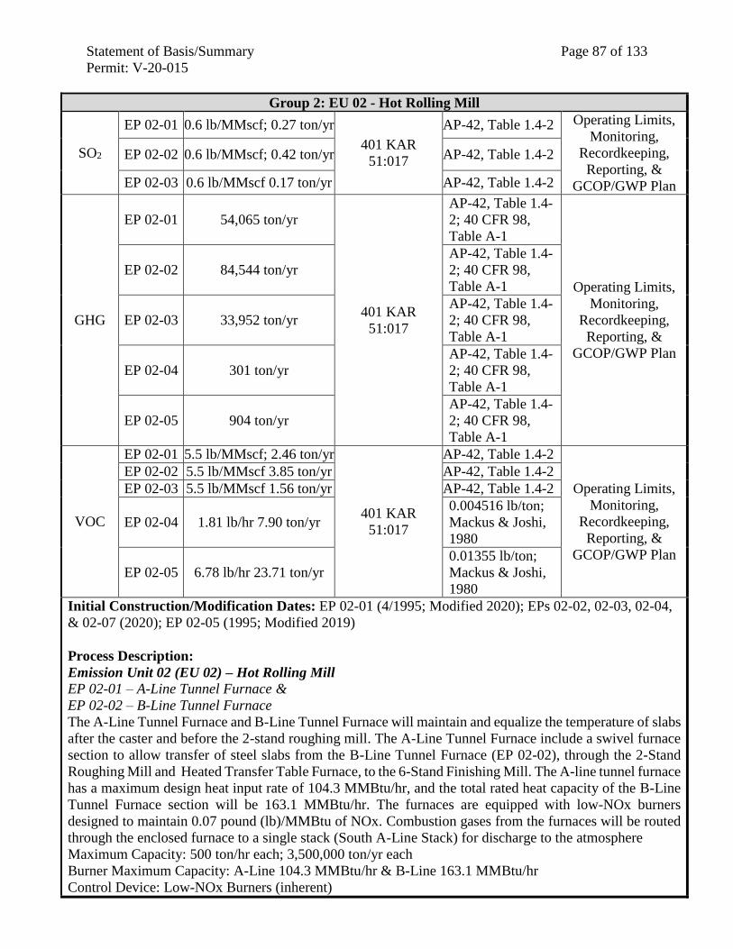
Statement of Basis/Summary Page 87 of 133
Permit: V-20-015
Group 2: EU 02 - Hot Rolling Mill
SO2
EP 02-01 0.6 lb/MMscf; 0.27 ton/yr
401 KAR
51:017
AP-42, Table 1.4-2 Operating Limits,
Monitoring,
Recordkeeping,
Reporting, &
GCOP/GWP Plan
EP 02-02 0.6 lb/MMscf; 0.42 ton/yr AP-42, Table 1.4-2
EP 02-03 0.6 lb/MMscf 0.17 ton/yr AP-42, Table 1.4-2
GHG
EP 02-01 54,065 ton/yr
401 KAR
51:017
AP-42, Table 1.4-
2; 40 CFR 98,
Table A-1
Operating Limits,
Monitoring,
Recordkeeping,
Reporting, &
GCOP/GWP Plan
EP 02-02 84,544 ton/yr
AP-42, Table 1.4-
2; 40 CFR 98,
Table A-1
EP 02-03 33,952 ton/yr
AP-42, Table 1.4-
2; 40 CFR 98,
Table A-1
EP 02-04 301 ton/yr
AP-42, Table 1.4-
2; 40 CFR 98,
Table A-1
EP 02-05 904 ton/yr
AP-42, Table 1.4-
2; 40 CFR 98,
Table A-1
VOC
EP 02-01 5.5 lb/MMscf; 2.46 ton/yr
401 KAR
51:017
AP-42, Table 1.4-2
Operating Limits,
Monitoring,
Recordkeeping,
Reporting, &
GCOP/GWP Plan
EP 02-02 5.5 lb/MMscf 3.85 ton/yr AP-42, Table 1.4-2
EP 02-03 5.5 lb/MMscf 1.56 ton/yr AP-42, Table 1.4-2
EP 02-04 1.81 lb/hr 7.90 ton/yr
0.004516 lb/ton;
Mackus & Joshi,
1980
EP 02-05 6.78 lb/hr 23.71 ton/yr
0.01355 lb/ton;
Mackus & Joshi,
1980
Initial Construction/Modification Dates: EP 02-01 (4/1995; Modified 2020); EPs 02-02, 02-03, 02-04,
& 02-07 (2020); EP 02-05 (1995; Modified 2019)
Process Description:
Emission Unit 02 (EU 02) – Hot Rolling Mill
EP 02-01 – A-Line Tunnel Furnace &
EP 02-02 – B-Line Tunnel Furnace
The A-Line Tunnel Furnace and B-Line Tunnel Furnace will maintain and equalize the temperature of slabs
after the caster and before the 2-stand roughing mill. The A-Line Tunnel Furnace include a swivel furnace
section to allow transfer of steel slabs from the B-Line Tunnel Furnace (EP 02-02), through the 2-Stand
Roughing Mill and Heated Transfer Table Furnace, to the 6-Stand Finishing Mill. The A-line tunnel furnace
has a maximum design heat input rate of 104.3 MMBtu/hr, and the total rated heat capacity of the B-Line
Tunnel Furnace section will be 163.1 MMBtu/hr. The furnaces are equipped with low-NOx burners
designed to maintain 0.07 pound (lb)/MMBtu of NOx. Combustion gases from the furnaces will be routed
through the enclosed furnace to a single stack (South A-Line Stack) for discharge to the atmosphere
Maximum Capacity: 500 ton/hr each; 3,500,000 ton/yr each
Burner Maximum Capacity: A-Line 104.3 MMBtu/hr & B-Line 163.1 MMBtu/hr
Control Device: Low-NOx Burners (inherent)
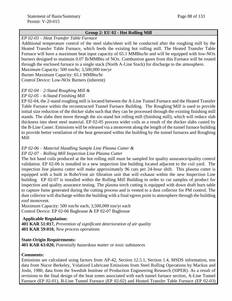
Statement of Basis/Summary Page 88 of 133
Permit: V-20-015
Group 2: EU 02 - Hot Rolling Mill
EP 02-03 – Heat Transfer Table Furnace
Additional temperature control of the steel slabs/sheet will be conducted after the roughing mill by the
Heated Transfer Table Furnace, which feeds the existing hot rolling mill. The Heated Transfer Table
Furnace will have a maximum heat input capacity of 65.1 MMBtu/hr and will be equipped with low-NOx
burners designed to maintain 0.07 lb/MMBtu of NOx. Combustion gases from this Furnace will be routed
through the enclosed furnace to a single stack (North A-Line Stack) for discharge to the atmosphere.
Maximum Capacity: 500 ton/hr; 3,500,000 ton/yr
Burner Maximum Capacity: 65.1 MMBtu/hr
Control Device: Low-NOx Burners (inherent)
EP 02-04 – 2-Stand Roughing Mill &
EP 02-05 – 6-Stand Finishing Mill
EP 02-04, the 2-stand roughing mill is located between the A-Line Tunnel Furnace and the Heated Transfer
Table Furnace within the reconstructed Tunnel Furnace Building. The Roughing Mill is used to provide
initial size reduction of the thicker slabs such that they can be processed through the existing finishing mill
stands. The slabs then move through the six-stand hot rolling mill (finishing mill), which will reduce slab
thickness into sheet steel material. EP 02-05 process wider coils as a result of the thicker slabs casted by
the B-Line Caster. Emissions will be released via a monovent along the length of the tunnel furnace building
to provide better ventilation of the heat generated within the building by the tunnel furnaces and Roughing
Mill
EP 02-06 – Material Handling Sample Line Plasma Cutter &
EP 02-07 – Rolling Mill Inspection Line Plasma Cutter
The hot band coils produced at the hot rolling mill must be sampled for quality assurance/quality control
validation. EP 02-06 is installed in a new inspection line building located adjacent to the coil yard. The
inspection line plasma cutter will make approximately 96 cuts per 24-hour shift. This plasma cutter is
equipped with a built in RoboVent air filtration unit that will exhaust within the new Inspection Line
building. EP 02-07 is installed within the Rolling Mill Building in order to cut samples of product for
inspection and quality assurance testing. The plasma torch cutting is equipped with down draft burn table
to capture fume generated during the cutting process and is vented to a dust collector for PM control. The
dust collector will discharge within the building with a final egress point to atmosphere through the building
roof monovent.
Maximum Capacity: 500 ton/hr each; 3,500,000 ton/yr each
Control Device: EP 02-06 Baghouse & EP 02-07 Baghouse
Applicable Regulation:
401 KAR 51:017, Prevention of significant deterioration of air quality
401 KAR 59:010, New process operations
State-Origin Requirements:
401 KAR 63:020, Potentially hazardous matter or toxic substances
Comments: Emissions are calculated using factors from AP-42, Section 12.5.1, Section 1.4, MSDS information, test
data from Nucor Berkeley, Volatized Lubricant Emissions from Steel Rolling Operations by Mackus and
Joshi, 1980, data from the Swedish Institute of Production Engineering Research (SIPER). As a result of
revisions to the final design of the heat zones associated with each tunnel furnace section, A-Line Tunnel
Furnace (EP 02-01), B-Line Tunnel Furnace (EP 02-02) and Heated Transfer Table Furnace (EP 02-03)
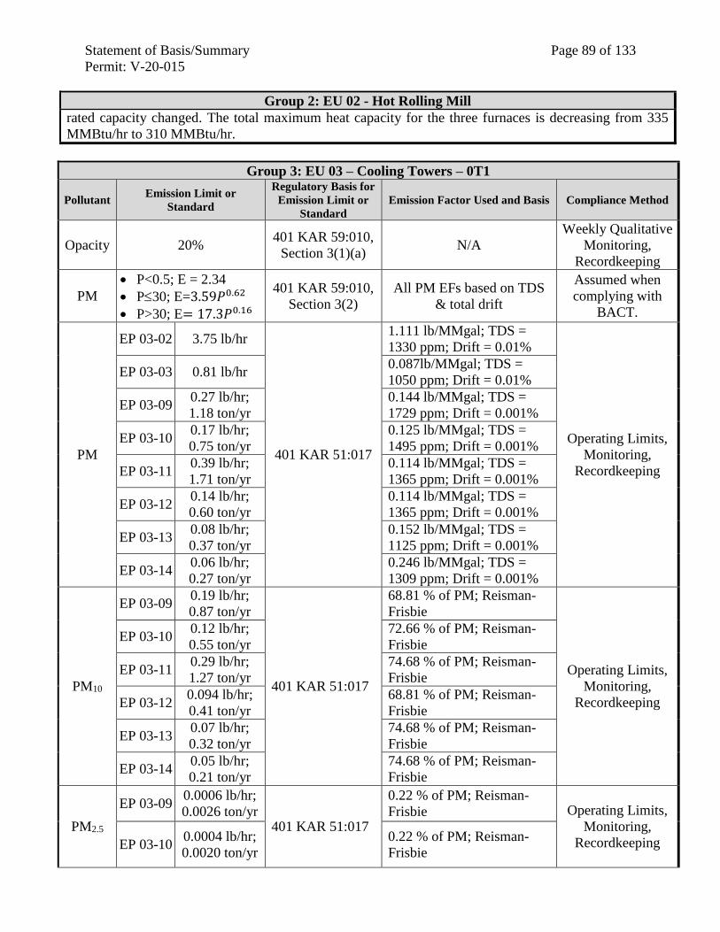
Statement of Basis/Summary Page 89 of 133
Permit: V-20-015
Group 2: EU 02 - Hot Rolling Mill
rated capacity changed. The total maximum heat capacity for the three furnaces is decreasing from 335
MMBtu/hr to 310 MMBtu/hr.
Group 3: EU 03 – Cooling Towers – 0T1
Pollutant Emission Limit or
Standard
Regulatory Basis for
Emission Limit or
Standard
Emission Factor Used and Basis Compliance Method
Opacity 20% 401 KAR 59:010,
Section 3(1)(a) N/A
Weekly Qualitative
Monitoring,
Recordkeeping
PM
P<0.5; E = 2.34
P30; E=3.59𝑃0.62
P>30; E= 17.3𝑃0.16
401 KAR 59:010,
Section 3(2)
All PM EFs based on TDS
& total drift
Assumed when
complying with
BACT.
PM
EP 03-02 3.75 lb/hr
401 KAR 51:017
1.111 lb/MMgal; TDS =
1330 ppm; Drift = 0.01%
Operating Limits,
Monitoring,
Recordkeeping
EP 03-03 0.81 lb/hr 0.087lb/MMgal; TDS =
1050 ppm; Drift = 0.01%
EP 03-09 0.27 lb/hr;
1.18 ton/yr
0.144 lb/MMgal; TDS =
1729 ppm; Drift = 0.001%
EP 03-10 0.17 lb/hr;
0.75 ton/yr
0.125 lb/MMgal; TDS =
1495 ppm; Drift = 0.001%
EP 03-11 0.39 lb/hr;
1.71 ton/yr
0.114 lb/MMgal; TDS =
1365 ppm; Drift = 0.001%
EP 03-12 0.14 lb/hr;
0.60 ton/yr
0.114 lb/MMgal; TDS =
1365 ppm; Drift = 0.001%
EP 03-13 0.08 lb/hr;
0.37 ton/yr
0.152 lb/MMgal; TDS =
1125 ppm; Drift = 0.001%
EP 03-14 0.06 lb/hr;
0.27 ton/yr
0.246 lb/MMgal; TDS =
1309 ppm; Drift = 0.001%
PM10
EP 03-09 0.19 lb/hr;
0.87 ton/yr
401 KAR 51:017
68.81 % of PM; Reisman-
Frisbie
Operating Limits,
Monitoring,
Recordkeeping
EP 03-10 0.12 lb/hr;
0.55 ton/yr
72.66 % of PM; Reisman-
Frisbie
EP 03-11 0.29 lb/hr;
1.27 ton/yr
74.68 % of PM; Reisman-
Frisbie
EP 03-12 0.094 lb/hr;
0.41 ton/yr
68.81 % of PM; Reisman-
Frisbie
EP 03-13 0.07 lb/hr;
0.32 ton/yr
74.68 % of PM; Reisman-
Frisbie
EP 03-14 0.05 lb/hr;
0.21 ton/yr
74.68 % of PM; Reisman-
Frisbie
PM2.5
EP 03-09 0.0006 lb/hr;
0.0026 ton/yr 401 KAR 51:017
0.22 % of PM; Reisman-
Frisbie Operating Limits,
Monitoring,
Recordkeeping EP 03-10 0.0004 lb/hr;
0.0020 ton/yr
0.22 % of PM; Reisman-
Frisbie
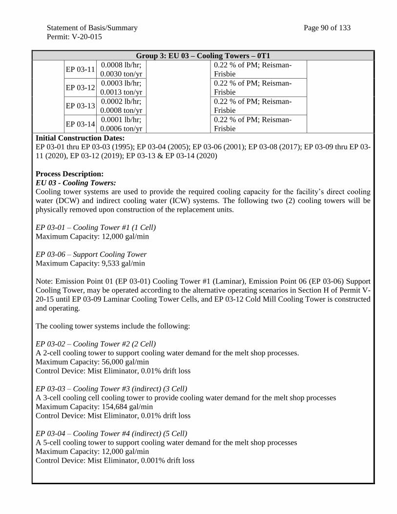
Statement of Basis/Summary Page 90 of 133
Permit: V-20-015
Group 3: EU 03 – Cooling Towers – 0T1
EP 03-11 0.0008 lb/hr;
0.0030 ton/yr
0.22 % of PM; Reisman-
Frisbie
EP 03-12 0.0003 lb/hr;
0.0013 ton/yr
0.22 % of PM; Reisman-
Frisbie
EP 03-13 0.0002 lb/hr;
0.0008 ton/yr
0.22 % of PM; Reisman-
Frisbie
EP 03-14 0.0001 lb/hr;
0.0006 ton/yr
0.22 % of PM; Reisman-
Frisbie
Initial Construction Dates: EP 03-01 thru EP 03-03 (1995); EP 03-04 (2005); EP 03-06 (2001); EP 03-08 (2017); EP 03-09 thru EP 03-
11 (2020), EP 03-12 (2019); EP 03-13 & EP 03-14 (2020)
Process Description:
EU 03 - Cooling Towers:
Cooling tower systems are used to provide the required cooling capacity for the facility’s direct cooling
water (DCW) and indirect cooling water (ICW) systems. The following two (2) cooling towers will be
physically removed upon construction of the replacement units.
EP 03-01 – Cooling Tower #1 (1 Cell)
Maximum Capacity: 12,000 gal/min
EP 03-06 – Support Cooling Tower
Maximum Capacity: 9,533 gal/min
Note: Emission Point 01 (EP 03-01) Cooling Tower #1 (Laminar), Emission Point 06 (EP 03-06) Support
Cooling Tower, may be operated according to the alternative operating scenarios in Section H of Permit V-
20-15 until EP 03-09 Laminar Cooling Tower Cells, and EP 03-12 Cold Mill Cooling Tower is constructed
and operating.
The cooling tower systems include the following:
EP 03-02 – Cooling Tower #2 (2 Cell)
A 2-cell cooling tower to support cooling water demand for the melt shop processes.
Maximum Capacity: 56,000 gal/min
Control Device: Mist Eliminator, 0.01% drift loss
EP 03-03 – Cooling Tower #3 (indirect) (3 Cell)
A 3-cell cooling cell cooling tower to provide cooling water demand for the melt shop processes
Maximum Capacity: 154,684 gal/min
Control Device: Mist Eliminator, 0.01% drift loss
EP 03-04 – Cooling Tower #4 (indirect) (5 Cell)
A 5-cell cooling tower to support cooling water demand for the melt shop processes
Maximum Capacity: 12,000 gal/min
Control Device: Mist Eliminator, 0.001% drift loss
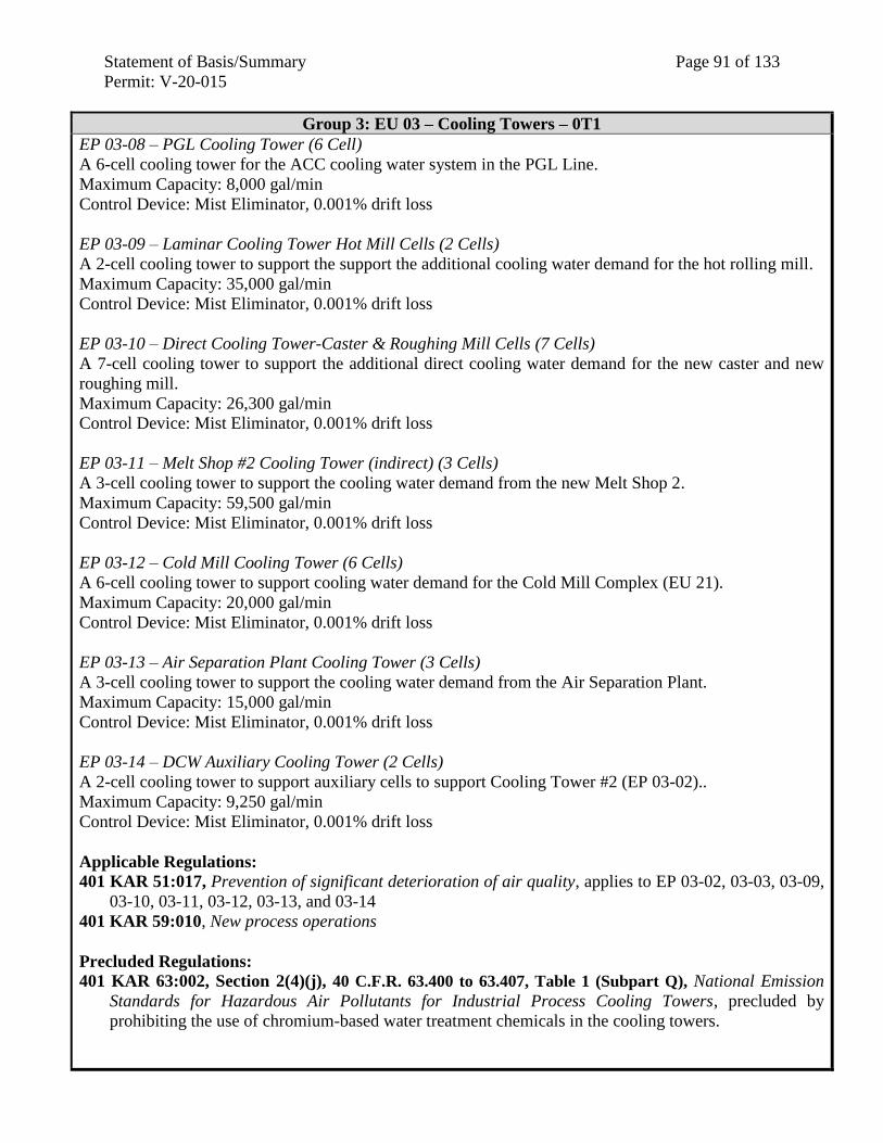
Statement of Basis/Summary Page 91 of 133
Permit: V-20-015
Group 3: EU 03 – Cooling Towers – 0T1
EP 03-08 – PGL Cooling Tower (6 Cell)
A 6-cell cooling tower for the ACC cooling water system in the PGL Line.
Maximum Capacity: 8,000 gal/min
Control Device: Mist Eliminator, 0.001% drift loss
EP 03-09 – Laminar Cooling Tower Hot Mill Cells (2 Cells)
A 2-cell cooling tower to support the support the additional cooling water demand for the hot rolling mill.
Maximum Capacity: 35,000 gal/min
Control Device: Mist Eliminator, 0.001% drift loss
EP 03-10 – Direct Cooling Tower-Caster & Roughing Mill Cells (7 Cells)
A 7-cell cooling tower to support the additional direct cooling water demand for the new caster and new
roughing mill.
Maximum Capacity: 26,300 gal/min
Control Device: Mist Eliminator, 0.001% drift loss
EP 03-11 – Melt Shop #2 Cooling Tower (indirect) (3 Cells)
A 3-cell cooling tower to support the cooling water demand from the new Melt Shop 2.
Maximum Capacity: 59,500 gal/min
Control Device: Mist Eliminator, 0.001% drift loss
EP 03-12 – Cold Mill Cooling Tower (6 Cells)
A 6-cell cooling tower to support cooling water demand for the Cold Mill Complex (EU 21).
Maximum Capacity: 20,000 gal/min
Control Device: Mist Eliminator, 0.001% drift loss
EP 03-13 – Air Separation Plant Cooling Tower (3 Cells)
A 3-cell cooling tower to support the cooling water demand from the Air Separation Plant.
Maximum Capacity: 15,000 gal/min
Control Device: Mist Eliminator, 0.001% drift loss
EP 03-14 – DCW Auxiliary Cooling Tower (2 Cells)
A 2-cell cooling tower to support auxiliary cells to support Cooling Tower #2 (EP 03-02)..
Maximum Capacity: 9,250 gal/min
Control Device: Mist Eliminator, 0.001% drift loss
Applicable Regulations:
401 KAR 51:017, Prevention of significant deterioration of air quality, applies to EP 03-02, 03-03, 03-09,
03-10, 03-11, 03-12, 03-13, and 03-14
401 KAR 59:010, New process operations
Precluded Regulations:
401 KAR 63:002, Section 2(4)(j), 40 C.F.R. 63.400 to 63.407, Table 1 (Subpart Q), National Emission
Standards for Hazardous Air Pollutants for Industrial Process Cooling Towers, precluded by
prohibiting the use of chromium-based water treatment chemicals in the cooling towers.
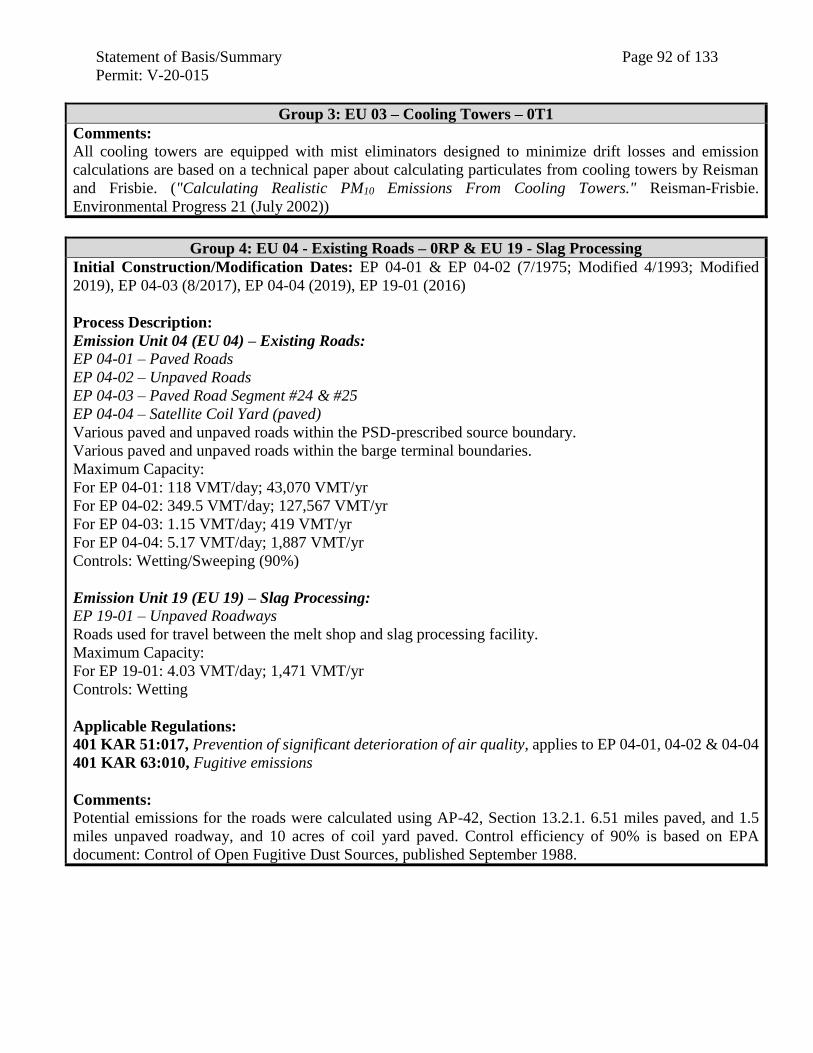
Statement of Basis/Summary Page 92 of 133
Permit: V-20-015
Group 3: EU 03 – Cooling Towers – 0T1
Comments:
All cooling towers are equipped with mist eliminators designed to minimize drift losses and emission
calculations are based on a technical paper about calculating particulates from cooling towers by Reisman
and Frisbie. ("Calculating Realistic PM10 Emissions From Cooling Towers." Reisman-Frisbie.
Environmental Progress 21 (July 2002))
Group 4: EU 04 - Existing Roads – 0RP & EU 19 - Slag Processing
Initial Construction/Modification Dates: EP 04-01 & EP 04-02 (7/1975; Modified 4/1993; Modified
2019), EP 04-03 (8/2017), EP 04-04 (2019), EP 19-01 (2016)
Process Description:
Emission Unit 04 (EU 04) – Existing Roads:
EP 04-01 – Paved Roads
EP 04-02 – Unpaved Roads
EP 04-03 – Paved Road Segment #24 & #25
EP 04-04 – Satellite Coil Yard (paved)
Various paved and unpaved roads within the PSD-prescribed source boundary.
Various paved and unpaved roads within the barge terminal boundaries.
Maximum Capacity:
For EP 04-01: 118 VMT/day; 43,070 VMT/yr
For EP 04-02: 349.5 VMT/day; 127,567 VMT/yr
For EP 04-03: 1.15 VMT/day; 419 VMT/yr
For EP 04-04: 5.17 VMT/day; 1,887 VMT/yr
Controls: Wetting/Sweeping (90%)
Emission Unit 19 (EU 19) – Slag Processing: EP 19-01 – Unpaved Roadways
Roads used for travel between the melt shop and slag processing facility.
Maximum Capacity:
For EP 19-01: 4.03 VMT/day; 1,471 VMT/yr
Controls: Wetting
Applicable Regulations:
401 KAR 51:017, Prevention of significant deterioration of air quality, applies to EP 04-01, 04-02 & 04-04
401 KAR 63:010, Fugitive emissions
Comments: Potential emissions for the roads were calculated using AP-42, Section 13.2.1. 6.51 miles paved, and 1.5
miles unpaved roadway, and 10 acres of coil yard paved. Control efficiency of 90% is based on EPA
document: Control of Open Fugitive Dust Sources, published September 1988.
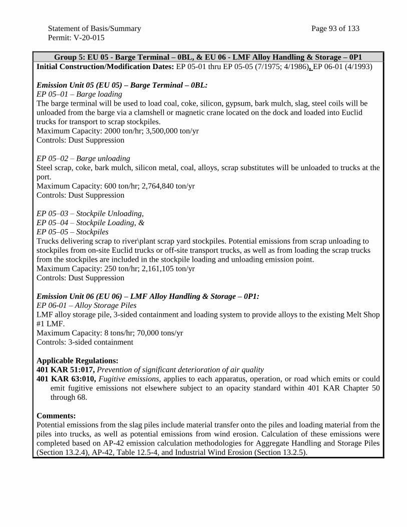
Statement of Basis/Summary Page 93 of 133
Permit: V-20-015
Group 5: EU 05 - Barge Terminal – 0BL, & EU 06 - LMF Alloy Handling & Storage – 0P1
Initial Construction/Modification Dates: EP 05-01 thru EP 05-05 (7/1975; 4/1986), EP 06-01 (4/1993)
Emission Unit 05 (EU 05) – Barge Terminal – 0BL: EP 05–01 – Barge loading
The barge terminal will be used to load coal, coke, silicon, gypsum, bark mulch, slag, steel coils will be
unloaded from the barge via a clamshell or magnetic crane located on the dock and loaded into Euclid
trucks for transport to scrap stockpiles.
Maximum Capacity: 2000 ton/hr; 3,500,000 ton/yr
Controls: Dust Suppression
EP 05–02 – Barge unloading
Steel scrap, coke, bark mulch, silicon metal, coal, alloys, scrap substitutes will be unloaded to trucks at the
port.
Maximum Capacity: 600 ton/hr; 2,764,840 ton/yr
Controls: Dust Suppression
EP 05–03 – Stockpile Unloading,
EP 05–04 – Stockpile Loading, &
EP 05–05 – Stockpiles
Trucks delivering scrap to river\plant scrap yard stockpiles. Potential emissions from scrap unloading to
stockpiles from on-site Euclid trucks or off-site transport trucks, as well as from loading the scrap trucks
from the stockpiles are included in the stockpile loading and unloading emission point.
Maximum Capacity: 250 ton/hr; 2,161,105 ton/yr
Controls: Dust Suppression
Emission Unit 06 (EU 06) – LMF Alloy Handling & Storage – 0P1: EP 06-01 – Alloy Storage Piles
LMF alloy storage pile, 3-sided containment and loading system to provide alloys to the existing Melt Shop
#1 LMF.
Maximum Capacity: 8 tons/hr; 70,000 tons/yr
Controls: 3-sided containment
Applicable Regulations:
401 KAR 51:017, Prevention of significant deterioration of air quality
401 KAR 63:010, Fugitive emissions, applies to each apparatus, operation, or road which emits or could
emit fugitive emissions not elsewhere subject to an opacity standard within 401 KAR Chapter 50
through 68.
Comments: Potential emissions from the slag piles include material transfer onto the piles and loading material from the
piles into trucks, as well as potential emissions from wind erosion. Calculation of these emissions were
completed based on AP-42 emission calculation methodologies for Aggregate Handling and Storage Piles
(Section 13.2.4), AP-42, Table 12.5-4, and Industrial Wind Erosion (Section 13.2.5).
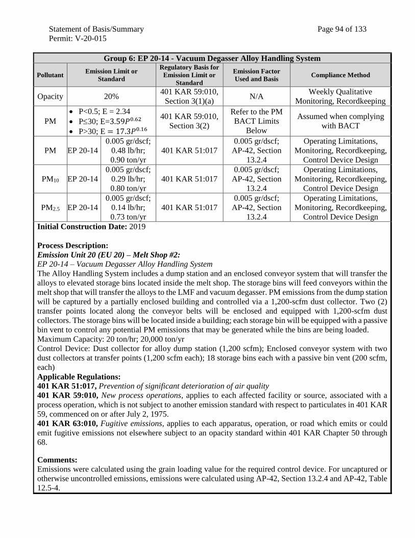
Statement of Basis/Summary Page 94 of 133
Permit: V-20-015
Group 6: EP 20-14 - Vacuum Degasser Alloy Handling System
Pollutant Emission Limit or
Standard
Regulatory Basis for
Emission Limit or
Standard
Emission Factor
Used and Basis Compliance Method
Opacity 20% 401 KAR 59:010,
Section 3(1)(a) N/A
Weekly Qualitative
Monitoring, Recordkeeping
PM
P<0.5; E = 2.34
P30; E=3.59𝑃0.62
P>30; E = 17.3𝑃0.16
401 KAR 59:010,
Section 3(2)
Refer to the PM
BACT Limits
Below
Assumed when complying
with BACT
PM EP 20-14
0.005 gr/dscf;
0.48 lb/hr;
0.90 ton/yr
401 KAR 51:017
0.005 gr/dscf;
AP-42, Section
13.2.4
Operating Limitations,
Monitoring, Recordkeeping,
Control Device Design
PM10 EP 20-14
0.005 gr/dscf;
0.29 lb/hr;
0.80 ton/yr
401 KAR 51:017
0.005 gr/dscf;
AP-42, Section
13.2.4
Operating Limitations,
Monitoring, Recordkeeping,
Control Device Design
PM2.5 EP 20-14
0.005 gr/dscf;
0.14 lb/hr;
0.73 ton/yr
401 KAR 51:017
0.005 gr/dscf;
AP-42, Section
13.2.4
Operating Limitations,
Monitoring, Recordkeeping,
Control Device Design
Initial Construction Date: 2019
Process Description:
Emission Unit 20 (EU 20) – Melt Shop #2:
EP 20-14 – Vacuum Degasser Alloy Handling System
The Alloy Handling System includes a dump station and an enclosed conveyor system that will transfer the
alloys to elevated storage bins located inside the melt shop. The storage bins will feed conveyors within the
melt shop that will transfer the alloys to the LMF and vacuum degasser. PM emissions from the dump station
will be captured by a partially enclosed building and controlled via a 1,200-scfm dust collector. Two (2)
transfer points located along the conveyor belts will be enclosed and equipped with 1,200-scfm dust
collectors. The storage bins will be located inside a building; each storage bin will be equipped with a passive
bin vent to control any potential PM emissions that may be generated while the bins are being loaded.
Maximum Capacity: 20 ton/hr; 20,000 ton/yr
Control Device: Dust collector for alloy dump station (1,200 scfm); Enclosed conveyor system with two
dust collectors at transfer points (1,200 scfm each); 18 storage bins each with a passive bin vent (200 scfm,
each)
Applicable Regulations:
401 KAR 51:017, Prevention of significant deterioration of air quality
401 KAR 59:010, New process operations, applies to each affected facility or source, associated with a
process operation, which is not subject to another emission standard with respect to particulates in 401 KAR
59, commenced on or after July 2, 1975.
401 KAR 63:010, Fugitive emissions, applies to each apparatus, operation, or road which emits or could
emit fugitive emissions not elsewhere subject to an opacity standard within 401 KAR Chapter 50 through
68.
Comments: Emissions were calculated using the grain loading value for the required control device. For uncaptured or
otherwise uncontrolled emissions, emissions were calculated using AP-42, Section 13.2.4 and AP-42, Table
12.5-4.
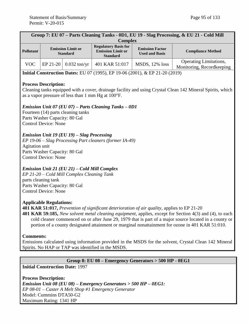
Statement of Basis/Summary Page 95 of 133
Permit: V-20-015
Group 7: EU 07 – Parts Cleaning Tanks - 0D1, EU 19 - Slag Processing, & EU 21 - Cold Mill
Complex
Pollutant Emission Limit or
Standard
Regulatory Basis for
Emission Limit or
Standard
Emission Factor
Used and Basis Compliance Method
VOC EP 21-20 0.032 ton/yr 401 KAR 51:017 MSDS, 12% loss Operating Limitations,
Monitoring, Recordkeeping
Initial Construction Dates: EU 07 (1995), EP 19-06 (2001), & EP 21-20 (2019)
Process Description: Cleaning tanks equipped with a cover, drainage facility and using Crystal Clean 142 Mineral Spirits, which
as a vapor pressure of less than 1 mm Hg at 100°F.
Emission Unit 07 (EU 07) – Parts Cleaning Tanks – 0D1 Fourteen (14) parts cleaning tanks
Parts Washer Capacity: 80 Gal
Control Device: None
Emission Unit 19 (EU 19) – Slag Processing EP 19-06 – Slag Processing Part cleaners (former IA-49)
Agitation unit
Parts Washer Capacity: 80 Gal
Control Device: None
Emission Unit 21 (EU 21) – Cold Mill Complex EP 21-20 – Cold Mill Complex Cleaning Tank
parts cleaning tank
Parts Washer Capacity: 80 Gal
Control Device: None
Applicable Regulations:
401 KAR 51:017, Prevention of significant deterioration of air quality, applies to EP 21-20
401 KAR 59:185, New solvent metal cleaning equipment, applies, except for Section 4(3) and (4), to each
cold cleaner commenced on or after June 29, 1979 that is part of a major source located in a county or
portion of a county designated attainment or marginal nonattainment for ozone in 401 KAR 51:010.
Comments: Emissions calculated using information provided in the MSDS for the solvent, Crystal Clean 142 Mineral
Spirits. No HAP or TAP was identified in the MSDS.
Group 8: EU 08 – Emergency Generators > 500 HP - 0EG1
Initial Construction Date: 1997
Process Description:
Emission Unit 08 (EU 08) – Emergency Generators > 500 HP – 0EG1: EP 08-01 – Caster A Melt Shop #1 Emergency Generator
Model: Cummins DTA50-G2
Maximum Rating: 1341 HP
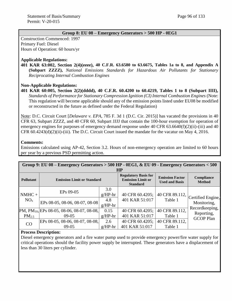
Statement of Basis/Summary Page 96 of 133
Permit: V-20-015
Group 8: EU 08 – Emergency Generators > 500 HP - 0EG1
Construction Commenced: 1997
Primary Fuel: Diesel
Hours of Operation: 60 hours/yr
Applicable Regulations:
401 KAR 63:002, Section 2(4)(eeee), 40 C.F.R. 63.6580 to 63.6675, Tables 1a to 8, and Appendix A
(Subpart ZZZZ), National Emissions Standards for Hazardous Air Pollutants for Stationary
Reciprocating Internal Combustion Engines
Non-Applicable Regulations:
401 KAR 60:005, Section 2(2)(dddd), 40 C.F.R. 60.4200 to 60.4219, Tables 1 to 8 (Subpart IIII),
Standards of Performance for Stationary Compression Ignition (CI) Internal Combustion Engines (Note:
This regulation will become applicable should any of the emission points listed under EU08 be modified
or reconstructed in the future as defined under the Federal Regulation)
Note: D.C. Circuit Court [Delaware v. EPA, 785 F. 3d 1 (D.C. Cir. 2015)] has vacated the provisions in 40
CFR 63, Subpart ZZZZ, and 40 CFR 60, Subpart JJJJ that contain the 100-hour exemption for operation of
emergency engines for purposes of emergency demand response under 40 CFR 63.6640(f)(2)(ii)-(iii) and 40
CFR 60.4243(d)(2)(ii)-(iii). The D.C. Circuit Court issued the mandate for the vacatur on May 4, 2016.
Comments: Emissions calculated using AP-42, Section 3.2. Hours of non-emergency operation are limited to 60 hours
per year by a previous PSD permitting action.
Group 9: EU 08 – Emergency Generators > 500 HP - 0EG1, & EU 09 - Emergency Generators < 500
HP
Pollutant Emission Limit or Standard
Regulatory Basis for
Emission Limit or
Standard
Emission Factor
Used and Basis
Compliance
Method
NMHC +
NOx
EPs 09-05 3.0
g/HP-hr 40 CFR 60.4205;
401 KAR 51:017
40 CFR 89.112,
Table 1 Certified Engine,
Monitoring,
Recordkeeping,
Reporting,
GCOP Plan
EPs 08-05, 08-06, 08-07, 08-08 4.8
g/HP-hr
PM, PM10,
PM2.5
EPs 08-05, 08-06, 08-07, 08-08,
09-05
0.15
g/HP-hr
40 CFR 60.4205;
401 KAR 51:017
40 CFR 89.112,
Table 1
CO EPs 08-05, 08-06, 08-07, 08-08,
09-05
2.6
g/HP-hr
40 CFR 60.4205;
401 KAR 51:017
40 CFR 89.112,
Table 1
Process Description: Diesel emergency generators and a fire water pump used to provide emergency power/fire water supply for
critical operations should the facility power supply be interrupted. These generators have a displacement of
less than 30 liters per cylinder.
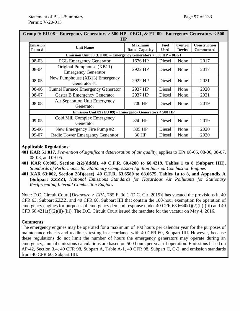
Statement of Basis/Summary Page 97 of 133
Permit: V-20-015
Group 9: EU 08 – Emergency Generators > 500 HP - 0EG1, & EU 09 - Emergency Generators < 500
HP
Emission
Point # Unit Name
Maximum
Rated Capacity
Fuel
Used
Control
Device
Construction
Commenced
Emission Unit 08 (EU 08) – Emergency Generators > 500 HP – 0EG1
08-03 PGL Emergency Generator 1676 HP Diesel None 2017
08-04 Original Pumphouse (XB11)
Emergency Generator 2922 HP Diesel None 2017
08-05 New Pumphouse (XB13) Emergency
Generator #1 2922 HP Diesel None 2021
08-06 Tunnel Furnace Emergency Generator 2937 HP Diesel None 2020
08-07 Caster B Emergency Generator 2937 HP Diesel None 2021
08-08 Air Separation Unit Emergency
Generator 700 HP Diesel None 2019
Emission Unit 09 (EU 09) – Emergency Generators < 500 HP
09-05 Cold Mill Complex Emergency
Generator 350 HP Diesel None 2019
09-06 New Emergency Fire Pump #2 305 HP Diesel None 2020
09-07 Radio Tower Emergency Generator 36 HP Diesel None 2020
Applicable Regulations:
401 KAR 51:017, Prevention of significant deterioration of air quality, applies to EPs 08-05, 08-06, 08-07,
08-08, and 09-05.
401 KAR 60:005, Section 2(2)(dddd), 40 C.F.R. 60.4200 to 60.4219, Tables 1 to 8 (Subpart IIII),
Standards of Performance for Stationary Compression Ignition Internal Combustion Engines
401 KAR 63:002, Section 2(4)(eeee), 40 C.F.R. 63.6580 to 63.6675, Tables 1a to 8, and Appendix A
(Subpart ZZZZ), National Emissions Standards for Hazardous Air Pollutants for Stationary
Reciprocating Internal Combustion Engines
Note: D.C. Circuit Court [Delaware v. EPA, 785 F. 3d 1 (D.C. Cir. 2015)] has vacated the provisions in 40
CFR 63, Subpart ZZZZ, and 40 CFR 60, Subpart IIII that contain the 100-hour exemption for operation of
emergency engines for purposes of emergency demand response under 40 CFR 63.6640(f)(2)(ii)-(iii) and 40
CFR 60.4211(f)(2)(ii)-(iii). The D.C. Circuit Court issued the mandate for the vacatur on May 4, 2016.
Comments: The emergency engines may be operated for a maximum of 100 hours per calendar year for the purposes of
maintenance checks and readiness testing in accordance with 40 CFR 60, Subpart IIII. However, because
these regulations do not limit the number of hours the emergency generators may operate during an
emergency, annual emissions calculations are based on 500 hours per year of operation. Emissions based on
AP-42, Section 3.4, 40 CFR 98, Subpart A, Table A-1, 40 CFR 98, Subpart C, C-2, and emission standards
from 40 CFR 60, Subpart IIII.
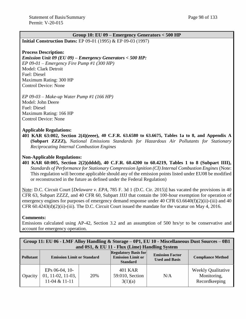
Statement of Basis/Summary Page 98 of 133
Permit: V-20-015
Group 10: EU 09 – Emergency Generators < 500 HP
Initial Construction Dates: EP 09-01 (1995) & EP 09-03 (1997)
Process Description:
Emission Unit 09 (EU 09) – Emergency Generators < 500 HP: EP 09-01 – Emergency Fire Pump #1 (300 HP)
Model: Clark Detroit
Fuel: Diesel
Maximum Rating: 300 HP
Control Device: None
EP 09-03 – Make-up Water Pump #1 (166 HP)
Model: John Deere
Fuel: Diesel
Maximum Rating: 166 HP
Control Device: None
Applicable Regulations:
401 KAR 63:002, Section 2(4)(eeee), 40 C.F.R. 63.6580 to 63.6675, Tables 1a to 8, and Appendix A
(Subpart ZZZZ), National Emissions Standards for Hazardous Air Pollutants for Stationary
Reciprocating Internal Combustion Engines
Non-Applicable Regulations:
401 KAR 60:005, Section 2(2)(dddd), 40 C.F.R. 60.4200 to 60.4219, Tables 1 to 8 (Subpart IIII),
Standards of Performance for Stationary Compression Ignition (CI) Internal Combustion Engines (Note:
This regulation will become applicable should any of the emission points listed under EU08 be modified
or reconstructed in the future as defined under the Federal Regulation)
Note: D.C. Circuit Court [Delaware v. EPA, 785 F. 3d 1 (D.C. Cir. 2015)] has vacated the provisions in 40
CFR 63, Subpart ZZZZ, and 40 CFR 60, Subpart JJJJ that contain the 100-hour exemption for operation of
emergency engines for purposes of emergency demand response under 40 CFR 63.6640(f)(2)(ii)-(iii) and 40
CFR 60.4243(d)(2)(ii)-(iii). The D.C. Circuit Court issued the mandate for the vacatur on May 4, 2016.
Comments: Emissions calculated using AP-42, Section 3.2 and an assumption of 500 hrs/yr to be conservative and
account for emergency operation.
Group 11: EU 06 - LMF Alloy Handling & Storage – 0P1, EU 10 - Miscellaneous Dust Sources – 0B1
and 0S1, & EU 11 - Flux (Lime) Handling System
Pollutant Emission Limit or Standard
Regulatory Basis for
Emission Limit or
Standard
Emission Factor
Used and Basis Compliance Method
Opacity
EPs 06-04, 10-
01, 11-02, 11-03,
11-04 & 11-11
20%
401 KAR
59:010, Section
3(1)(a)
N/A
Weekly Qualitative
Monitoring,
Recordkeeping
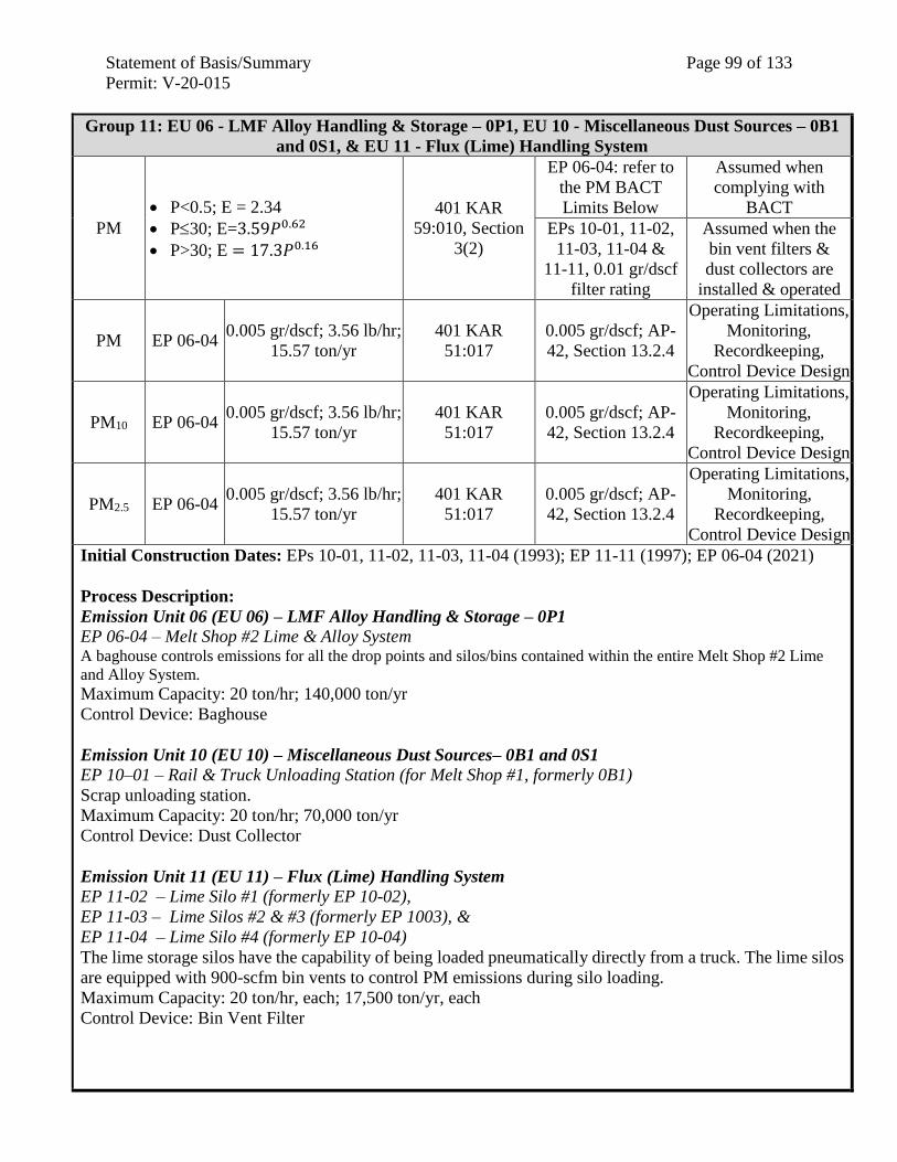
Statement of Basis/Summary Page 99 of 133
Permit: V-20-015
Group 11: EU 06 - LMF Alloy Handling & Storage – 0P1, EU 10 - Miscellaneous Dust Sources – 0B1
and 0S1, & EU 11 - Flux (Lime) Handling System
PM
P<0.5; E = 2.34
P30; E=3.59𝑃0.62
P>30; E = 17.3𝑃0.16
401 KAR
59:010, Section
3(2)
EP 06-04: refer to
the PM BACT
Limits Below
Assumed when
complying with
BACT
EPs 10-01, 11-02,
11-03, 11-04 &
11-11, 0.01 gr/dscf
filter rating
Assumed when the
bin vent filters &
dust collectors are
installed & operated
PM EP 06-04 0.005 gr/dscf; 3.56 lb/hr;
15.57 ton/yr
401 KAR
51:017
0.005 gr/dscf; AP-
42, Section 13.2.4
Operating Limitations,
Monitoring,
Recordkeeping,
Control Device Design
PM10 EP 06-04 0.005 gr/dscf; 3.56 lb/hr;
15.57 ton/yr
401 KAR
51:017
0.005 gr/dscf; AP-
42, Section 13.2.4
Operating Limitations,
Monitoring,
Recordkeeping,
Control Device Design
PM2.5 EP 06-04 0.005 gr/dscf; 3.56 lb/hr;
15.57 ton/yr
401 KAR
51:017
0.005 gr/dscf; AP-
42, Section 13.2.4
Operating Limitations,
Monitoring,
Recordkeeping,
Control Device Design
Initial Construction Dates: EPs 10-01, 11-02, 11-03, 11-04 (1993); EP 11-11 (1997); EP 06-04 (2021)
Process Description:
Emission Unit 06 (EU 06) – LMF Alloy Handling & Storage – 0P1
EP 06-04 – Melt Shop #2 Lime & Alloy System A baghouse controls emissions for all the drop points and silos/bins contained within the entire Melt Shop #2 Lime
and Alloy System. Maximum Capacity: 20 ton/hr; 140,000 ton/yr
Control Device: Baghouse
Emission Unit 10 (EU 10) – Miscellaneous Dust Sources– 0B1 and 0S1
EP 10–01 – Rail & Truck Unloading Station (for Melt Shop #1, formerly 0B1)
Scrap unloading station.
Maximum Capacity: 20 ton/hr; 70,000 ton/yr
Control Device: Dust Collector
Emission Unit 11 (EU 11) – Flux (Lime) Handling System
EP 11-02 – Lime Silo #1 (formerly EP 10-02),
EP 11-03 – Lime Silos #2 & #3 (formerly EP 1003), &
EP 11-04 – Lime Silo #4 (formerly EP 10-04)
The lime storage silos have the capability of being loaded pneumatically directly from a truck. The lime silos
are equipped with 900-scfm bin vents to control PM emissions during silo loading.
Maximum Capacity: 20 ton/hr, each; 17,500 ton/yr, each
Control Device: Bin Vent Filter
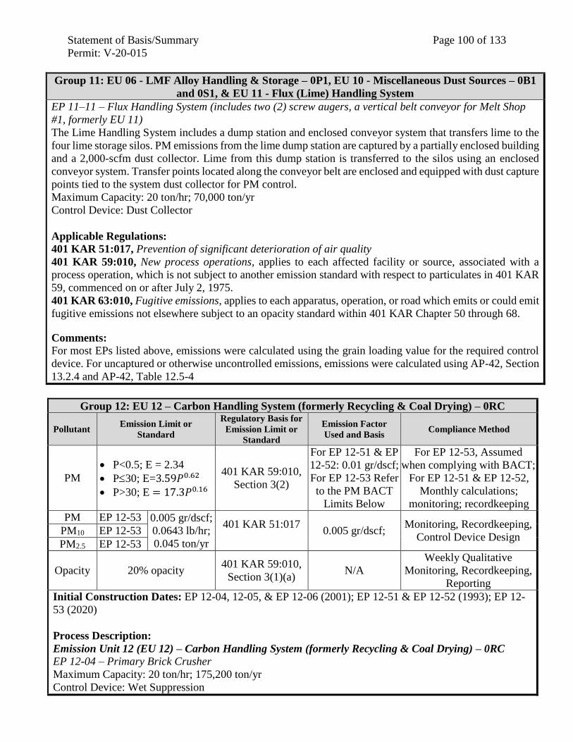
Statement of Basis/Summary Page 100 of 133
Permit: V-20-015
Group 11: EU 06 - LMF Alloy Handling & Storage – 0P1, EU 10 - Miscellaneous Dust Sources – 0B1
and 0S1, & EU 11 - Flux (Lime) Handling System
EP 11–11 – Flux Handling System (includes two (2) screw augers, a vertical belt conveyor for Melt Shop
#1, formerly EU 11)
The Lime Handling System includes a dump station and enclosed conveyor system that transfers lime to the
four lime storage silos. PM emissions from the lime dump station are captured by a partially enclosed building
and a 2,000-scfm dust collector. Lime from this dump station is transferred to the silos using an enclosed
conveyor system. Transfer points located along the conveyor belt are enclosed and equipped with dust capture
points tied to the system dust collector for PM control.
Maximum Capacity: 20 ton/hr; 70,000 ton/yr
Control Device: Dust Collector
Applicable Regulations:
401 KAR 51:017, Prevention of significant deterioration of air quality
401 KAR 59:010, New process operations, applies to each affected facility or source, associated with a
process operation, which is not subject to another emission standard with respect to particulates in 401 KAR
59, commenced on or after July 2, 1975.
401 KAR 63:010, Fugitive emissions, applies to each apparatus, operation, or road which emits or could emit
fugitive emissions not elsewhere subject to an opacity standard within 401 KAR Chapter 50 through 68.
Comments: For most EPs listed above, emissions were calculated using the grain loading value for the required control
device. For uncaptured or otherwise uncontrolled emissions, emissions were calculated using AP-42, Section
13.2.4 and AP-42, Table 12.5-4
Group 12: EU 12 – Carbon Handling System (formerly Recycling & Coal Drying) – 0RC
Pollutant Emission Limit or
Standard
Regulatory Basis for
Emission Limit or
Standard
Emission Factor
Used and Basis Compliance Method
PM
P<0.5; E = 2.34
P30; E=3.59𝑃0.62
P>30; E = 17.3𝑃0.16
401 KAR 59:010,
Section 3(2)
For EP 12-51 & EP
12-52: 0.01 gr/dscf;
For EP 12-53 Refer
to the PM BACT
Limits Below
For EP 12-53, Assumed
when complying with BACT;
For EP 12-51 & EP 12-52,
Monthly calculations;
monitoring; recordkeeping
PM EP 12-53 0.005 gr/dscf;
0.0643 lb/hr;
0.045 ton/yr
401 KAR 51:017
0.005 gr/dscf;
Monitoring, Recordkeeping,
Control Device Design PM10 EP 12-53
PM2.5 EP 12-53
Opacity 20% opacity 401 KAR 59:010,
Section 3(1)(a) N/A
Weekly Qualitative
Monitoring, Recordkeeping,
Reporting
Initial Construction Dates: EP 12-04, 12-05, & EP 12-06 (2001); EP 12-51 & EP 12-52 (1993); EP 12-
53 (2020)
Process Description:
Emission Unit 12 (EU 12) – Carbon Handling System (formerly Recycling & Coal Drying) – 0RC
EP 12-04 – Primary Brick Crusher
Maximum Capacity: 20 ton/hr; 175,200 ton/yr
Control Device: Wet Suppression
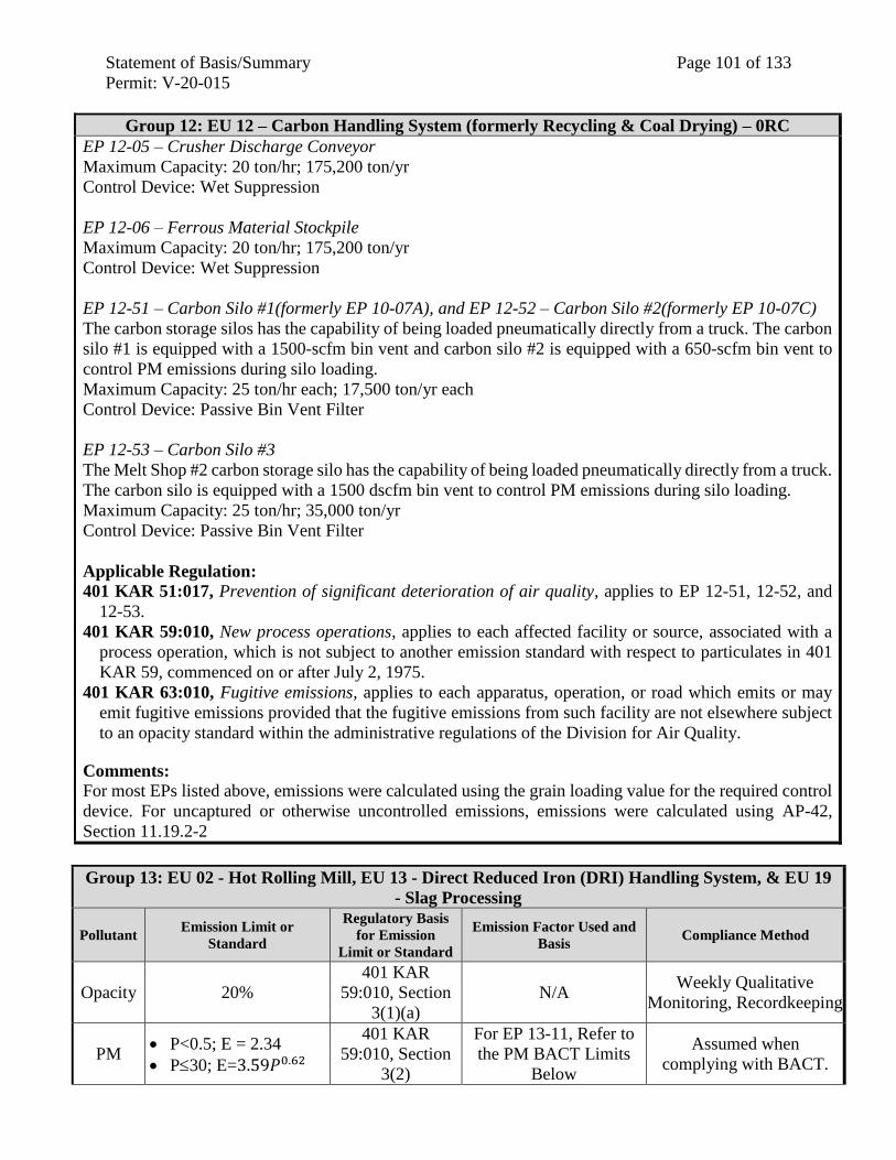
Statement of Basis/Summary Page 101 of 133
Permit: V-20-015
Group 12: EU 12 – Carbon Handling System (formerly Recycling & Coal Drying) – 0RC
EP 12-05 – Crusher Discharge Conveyor
Maximum Capacity: 20 ton/hr; 175,200 ton/yr
Control Device: Wet Suppression
EP 12-06 – Ferrous Material Stockpile
Maximum Capacity: 20 ton/hr; 175,200 ton/yr
Control Device: Wet Suppression
EP 12-51 – Carbon Silo #1(formerly EP 10-07A), and EP 12-52 – Carbon Silo #2(formerly EP 10-07C)
The carbon storage silos has the capability of being loaded pneumatically directly from a truck. The carbon
silo #1 is equipped with a 1500-scfm bin vent and carbon silo #2 is equipped with a 650-scfm bin vent to
control PM emissions during silo loading.
Maximum Capacity: 25 ton/hr each; 17,500 ton/yr each
Control Device: Passive Bin Vent Filter
EP 12-53 – Carbon Silo #3
The Melt Shop #2 carbon storage silo has the capability of being loaded pneumatically directly from a truck.
The carbon silo is equipped with a 1500 dscfm bin vent to control PM emissions during silo loading.
Maximum Capacity: 25 ton/hr; 35,000 ton/yr
Control Device: Passive Bin Vent Filter
Applicable Regulation:
401 KAR 51:017, Prevention of significant deterioration of air quality, applies to EP 12-51, 12-52, and
12-53.
401 KAR 59:010, New process operations, applies to each affected facility or source, associated with a
process operation, which is not subject to another emission standard with respect to particulates in 401
KAR 59, commenced on or after July 2, 1975.
401 KAR 63:010, Fugitive emissions, applies to each apparatus, operation, or road which emits or may
emit fugitive emissions provided that the fugitive emissions from such facility are not elsewhere subject
to an opacity standard within the administrative regulations of the Division for Air Quality.
Comments: For most EPs listed above, emissions were calculated using the grain loading value for the required control
device. For uncaptured or otherwise uncontrolled emissions, emissions were calculated using AP-42,
Section 11.19.2-2
Group 13: EU 02 - Hot Rolling Mill, EU 13 - Direct Reduced Iron (DRI) Handling System, & EU 19
- Slag Processing
Pollutant Emission Limit or
Standard
Regulatory Basis
for Emission
Limit or Standard
Emission Factor Used and
Basis Compliance Method
Opacity 20%
401 KAR
59:010, Section
3(1)(a)
N/A Weekly Qualitative
Monitoring, Recordkeeping
PM P<0.5; E = 2.34
P30; E=3.59𝑃0.62
401 KAR
59:010, Section
3(2)
For EP 13-11, Refer to
the PM BACT Limits
Below
Assumed when
complying with BACT.
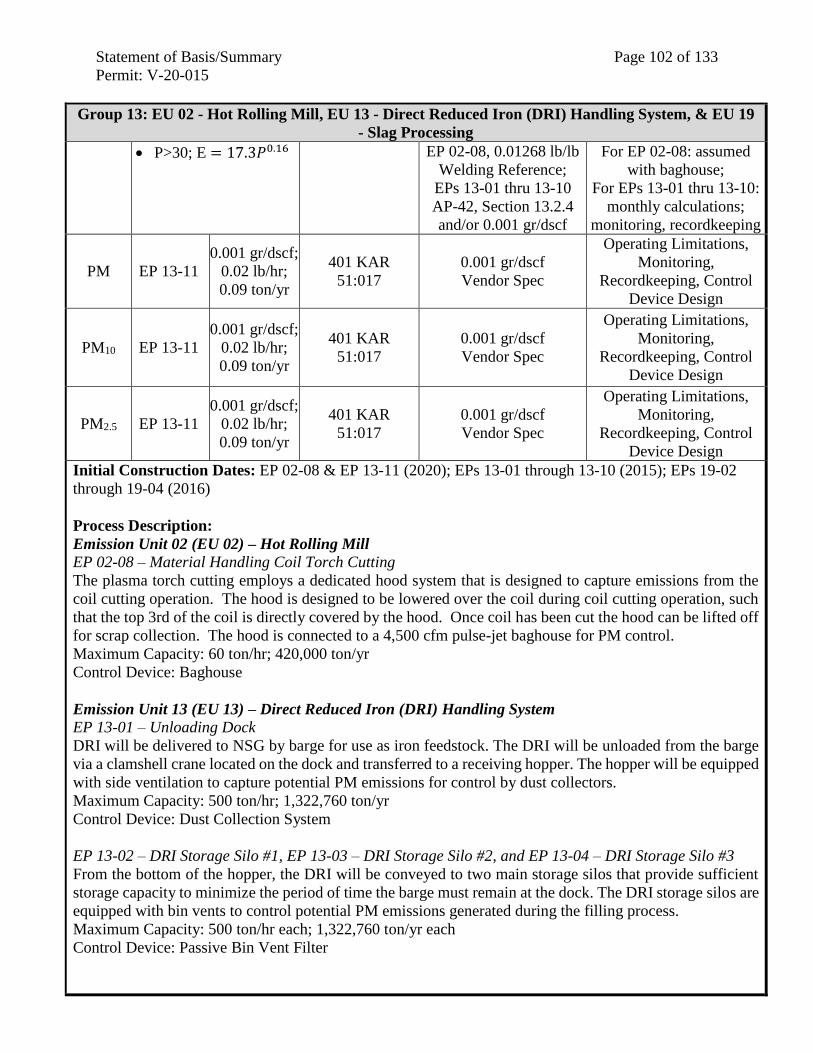
Statement of Basis/Summary Page 102 of 133
Permit: V-20-015
Group 13: EU 02 - Hot Rolling Mill, EU 13 - Direct Reduced Iron (DRI) Handling System, & EU 19
- Slag Processing
P>30; E = 17.3𝑃0.16 EP 02-08, 0.01268 lb/lb
Welding Reference;
EPs 13-01 thru 13-10
AP-42, Section 13.2.4
and/or 0.001 gr/dscf
For EP 02-08: assumed
with baghouse;
For EPs 13-01 thru 13-10:
monthly calculations;
monitoring, recordkeeping
PM EP 13-11
0.001 gr/dscf;
0.02 lb/hr;
0.09 ton/yr
401 KAR
51:017
0.001 gr/dscf
Vendor Spec
Operating Limitations,
Monitoring,
Recordkeeping, Control
Device Design
PM10 EP 13-11
0.001 gr/dscf;
0.02 lb/hr;
0.09 ton/yr
401 KAR
51:017
0.001 gr/dscf
Vendor Spec
Operating Limitations,
Monitoring,
Recordkeeping, Control
Device Design
PM2.5 EP 13-11
0.001 gr/dscf;
0.02 lb/hr;
0.09 ton/yr
401 KAR
51:017
0.001 gr/dscf
Vendor Spec
Operating Limitations,
Monitoring,
Recordkeeping, Control
Device Design
Initial Construction Dates: EP 02-08 & EP 13-11 (2020); EPs 13-01 through 13-10 (2015); EPs 19-02
through 19-04 (2016)
Process Description:
Emission Unit 02 (EU 02) – Hot Rolling Mill
EP 02-08 – Material Handling Coil Torch Cutting
The plasma torch cutting employs a dedicated hood system that is designed to capture emissions from the
coil cutting operation. The hood is designed to be lowered over the coil during coil cutting operation, such
that the top 3rd of the coil is directly covered by the hood. Once coil has been cut the hood can be lifted off
for scrap collection. The hood is connected to a 4,500 cfm pulse-jet baghouse for PM control.
Maximum Capacity: 60 ton/hr; 420,000 ton/yr
Control Device: Baghouse
Emission Unit 13 (EU 13) – Direct Reduced Iron (DRI) Handling System
EP 13-01 – Unloading Dock
DRI will be delivered to NSG by barge for use as iron feedstock. The DRI will be unloaded from the barge
via a clamshell crane located on the dock and transferred to a receiving hopper. The hopper will be equipped
with side ventilation to capture potential PM emissions for control by dust collectors.
Maximum Capacity: 500 ton/hr; 1,322,760 ton/yr
Control Device: Dust Collection System
EP 13-02 – DRI Storage Silo #1, EP 13-03 – DRI Storage Silo #2, and EP 13-04 – DRI Storage Silo #3
From the bottom of the hopper, the DRI will be conveyed to two main storage silos that provide sufficient
storage capacity to minimize the period of time the barge must remain at the dock. The DRI storage silos are
equipped with bin vents to control potential PM emissions generated during the filling process.
Maximum Capacity: 500 ton/hr each; 1,322,760 ton/yr each
Control Device: Passive Bin Vent Filter
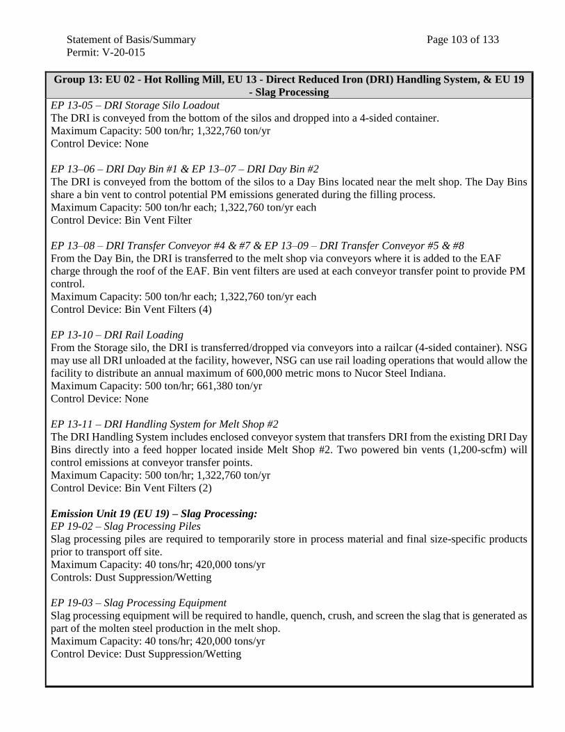
Statement of Basis/Summary Page 103 of 133
Permit: V-20-015
Group 13: EU 02 - Hot Rolling Mill, EU 13 - Direct Reduced Iron (DRI) Handling System, & EU 19
- Slag Processing
EP 13-05 – DRI Storage Silo Loadout
The DRI is conveyed from the bottom of the silos and dropped into a 4-sided container.
Maximum Capacity: 500 ton/hr; 1,322,760 ton/yr
Control Device: None
EP 13–06 – DRI Day Bin #1 & EP 13–07 – DRI Day Bin #2
The DRI is conveyed from the bottom of the silos to a Day Bins located near the melt shop. The Day Bins
share a bin vent to control potential PM emissions generated during the filling process.
Maximum Capacity: 500 ton/hr each; 1,322,760 ton/yr each
Control Device: Bin Vent Filter
EP 13–08 – DRI Transfer Conveyor #4 & #7 & EP 13–09 – DRI Transfer Conveyor #5 & #8
From the Day Bin, the DRI is transferred to the melt shop via conveyors where it is added to the EAF
charge through the roof of the EAF. Bin vent filters are used at each conveyor transfer point to provide PM
control.
Maximum Capacity: 500 ton/hr each; 1,322,760 ton/yr each
Control Device: Bin Vent Filters (4)
EP 13-10 – DRI Rail Loading
From the Storage silo, the DRI is transferred/dropped via conveyors into a railcar (4-sided container). NSG
may use all DRI unloaded at the facility, however, NSG can use rail loading operations that would allow the
facility to distribute an annual maximum of 600,000 metric mons to Nucor Steel Indiana.
Maximum Capacity: 500 ton/hr; 661,380 ton/yr
Control Device: None
EP 13-11 – DRI Handling System for Melt Shop #2
The DRI Handling System includes enclosed conveyor system that transfers DRI from the existing DRI Day
Bins directly into a feed hopper located inside Melt Shop #2. Two powered bin vents (1,200-scfm) will
control emissions at conveyor transfer points.
Maximum Capacity: 500 ton/hr; 1,322,760 ton/yr
Control Device: Bin Vent Filters (2)
Emission Unit 19 (EU 19) – Slag Processing:
EP 19-02 – Slag Processing Piles
Slag processing piles are required to temporarily store in process material and final size-specific products
prior to transport off site.
Maximum Capacity: 40 tons/hr; 420,000 tons/yr
Controls: Dust Suppression/Wetting
EP 19-03 – Slag Processing Equipment
Slag processing equipment will be required to handle, quench, crush, and screen the slag that is generated as
part of the molten steel production in the melt shop.
Maximum Capacity: 40 tons/hr; 420,000 tons/yr
Control Device: Dust Suppression/Wetting
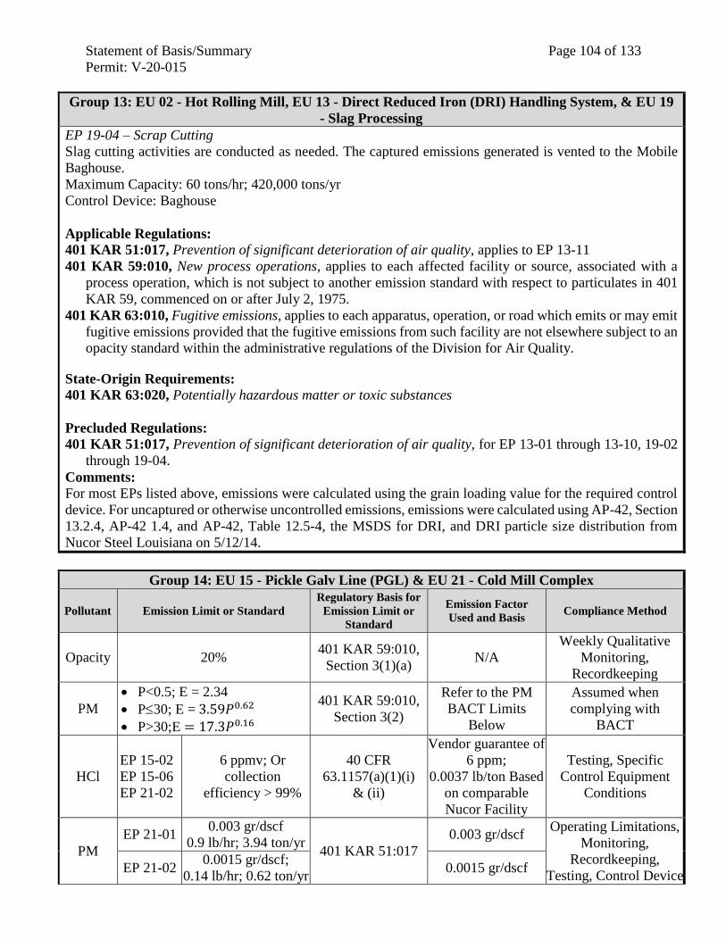
Statement of Basis/Summary Page 104 of 133
Permit: V-20-015
Group 13: EU 02 - Hot Rolling Mill, EU 13 - Direct Reduced Iron (DRI) Handling System, & EU 19
- Slag Processing
EP 19-04 – Scrap Cutting
Slag cutting activities are conducted as needed. The captured emissions generated is vented to the Mobile
Baghouse.
Maximum Capacity: 60 tons/hr; 420,000 tons/yr
Control Device: Baghouse
Applicable Regulations:
401 KAR 51:017, Prevention of significant deterioration of air quality, applies to EP 13-11
401 KAR 59:010, New process operations, applies to each affected facility or source, associated with a
process operation, which is not subject to another emission standard with respect to particulates in 401
KAR 59, commenced on or after July 2, 1975.
401 KAR 63:010, Fugitive emissions, applies to each apparatus, operation, or road which emits or may emit
fugitive emissions provided that the fugitive emissions from such facility are not elsewhere subject to an
opacity standard within the administrative regulations of the Division for Air Quality.
State-Origin Requirements:
401 KAR 63:020, Potentially hazardous matter or toxic substances
Precluded Regulations:
401 KAR 51:017, Prevention of significant deterioration of air quality, for EP 13-01 through 13-10, 19-02
through 19-04.
Comments: For most EPs listed above, emissions were calculated using the grain loading value for the required control
device. For uncaptured or otherwise uncontrolled emissions, emissions were calculated using AP-42, Section
13.2.4, AP-42 1.4, and AP-42, Table 12.5-4, the MSDS for DRI, and DRI particle size distribution from
Nucor Steel Louisiana on 5/12/14.
Group 14: EU 15 - Pickle Galv Line (PGL) & EU 21 - Cold Mill Complex
Pollutant Emission Limit or Standard
Regulatory Basis for
Emission Limit or
Standard
Emission Factor
Used and Basis Compliance Method
Opacity 20% 401 KAR 59:010,
Section 3(1)(a) N/A
Weekly Qualitative
Monitoring,
Recordkeeping
PM
P<0.5; E = 2.34
P30; E = 3.59𝑃0.62
P>30;E = 17.3𝑃0.16
401 KAR 59:010,
Section 3(2)
Refer to the PM
BACT Limits
Below
Assumed when
complying with
BACT
HCl
EP 15-02
EP 15-06
EP 21-02
6 ppmv; Or
collection
efficiency > 99%
40 CFR
63.1157(a)(1)(i)
& (ii)
Vendor guarantee of
6 ppm;
0.0037 lb/ton Based
on comparable
Nucor Facility
Testing, Specific
Control Equipment
Conditions
PM
EP 21-01 0.003 gr/dscf
0.9 lb/hr; 3.94 ton/yr 401 KAR 51:017
0.003 gr/dscf Operating Limitations,
Monitoring,
Recordkeeping,
Testing, Control Device EP 21-02
0.0015 gr/dscf;
0.14 lb/hr; 0.62 ton/yr 0.0015 gr/dscf
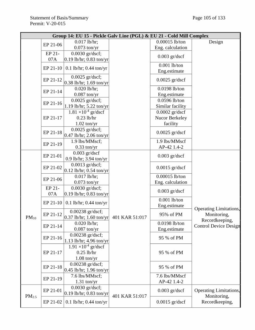
Statement of Basis/Summary Page 105 of 133
Permit: V-20-015
Group 14: EU 15 - Pickle Galv Line (PGL) & EU 21 - Cold Mill Complex
EP 21-06 0.017 lb/hr;
0.073 ton/yr
0.00015 lb/ton
Eng. calculation
Design
EP 21-
07A
0.0030 gr/dscf;
0.19 lb/hr; 0.83 ton/yr 0.003 gr/dscf
EP 21-10 0.1 lb/hr; 0.44 ton/yr 0.001 lb/ton
Eng.estimate
EP 21-12 0.0025 gr/dscf;
0.38 lb/hr; 1.69 ton/yr 0.0025 gr/dscf
EP 21-14 0.020 lb/hr;
0.087 ton/yr
0.0198 lb/ton
Eng.estimate
EP 21-16 0.0025 gr/dscf;
1.19 lb/hr; 5.22 ton/yr
0.0596 lb/ton
Similar facility
EP 21-17
1.81 ×10⁻⁴ gr/dscf
0.23 lb/hr
1.02 ton/yr
0.0002 gr/dscf
Nucor Berkeley
facility
EP 21-18 0.0025 gr/dscf;
0.47 lb/hr; 2.06 ton/yr 0.0025 gr/dscf
EP 21-19 1.9 lbs/MMscf;
0.33 ton/yr
1.9 lbs/MMscf
AP-42 1.4-2
PM10
EP 21-01 0.003 gr/dscf
0.9 lb/hr; 3.94 ton/yr
401 KAR 51:017
0.003 gr/dscf
Operating Limitations,
Monitoring,
Recordkeeping,
Control Device Design
EP 21-02 0.0013 gr/dscf;
0.12 lb/hr; 0.54 ton/yr 0.0015 gr/dscf
EP 21-06 0.017 lb/hr;
0.073 ton/yr
0.00015 lb/ton
Eng. calculation
EP 21-
07A
0.0030 gr/dscf;
0.19 lb/hr; 0.83 ton/yr 0.003 gr/dscf
EP 21-10 0.1 lb/hr; 0.44 ton/yr 0.001 lb/ton
Eng.estimate
EP 21-12 0.00238 gr/dscf;
0.37 lb/hr; 1.60 ton/yr 95% of PM
EP 21-14 0.020 lb/hr;
0.087 ton/yr
0.0198 lb/ton
Eng.estimate
EP 21-16 0.00238 gr/dscf;
1.13 lb/hr; 4.96 ton/yr 95 % of PM
EP 21-17
1.91 ×10⁻⁴ gr/dscf
0.25 lb/hr
1.08 ton/yr
95 % of PM
EP 21-18 0.00238 gr/dscf;
0.45 lb/hr; 1.96 ton/yr 95 % of PM
EP 21-19 7.6 lbs/MMscf;
1.31 ton/yr
7.6 lbs/MMscf
AP-42 1.4-2
PM2.5
EP 21-01 0.0030 gr/dscf;
0.19 lb/hr; 0.83 ton/yr 401 KAR 51:017
0.003 gr/dscf Operating Limitations,
Monitoring,
Recordkeeping, EP 21-02 0.1 lb/hr; 0.44 ton/yr 0.0015 gr/dscf
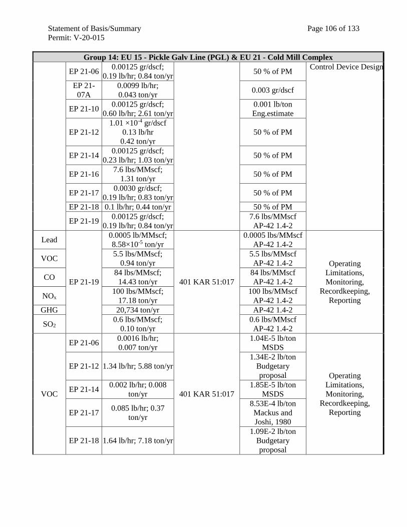
Statement of Basis/Summary Page 106 of 133
Permit: V-20-015
Group 14: EU 15 - Pickle Galv Line (PGL) & EU 21 - Cold Mill Complex
EP 21-06 0.00125 gr/dscf;
0.19 lb/hr; 0.84 ton/yr 50 % of PM
Control Device Design
EP 21-
07A
0.0099 lb/hr;
0.043 ton/yr 0.003 gr/dscf
EP 21-10 0.00125 gr/dscf;
0.60 lb/hr; 2.61 ton/yr
0.001 lb/ton
Eng.estimate
EP 21-12
1.01 ×10⁻⁴ gr/dscf
0.13 lb/hr
0.42 ton/yr
50 % of PM
EP 21-14 0.00125 gr/dscf;
0.23 lb/hr; 1.03 ton/yr 50 % of PM
EP 21-16 7.6 lbs/MMscf;
1.31 ton/yr 50 % of PM
EP 21-17 0.0030 gr/dscf;
0.19 lb/hr; 0.83 ton/yr 50 % of PM
EP 21-18 0.1 lb/hr; 0.44 ton/yr 50 % of PM
EP 21-19 0.00125 gr/dscf;
0.19 lb/hr; 0.84 ton/yr
7.6 lbs/MMscf
AP-42 1.4-2
Lead
EP 21-19
0.0005 lb/MMscf;
8.58×10⁻⁵ ton/yr
401 KAR 51:017
0.0005 lbs/MMscf
AP-42 1.4-2
Operating
Limitations,
Monitoring,
Recordkeeping,
Reporting
VOC 5.5 lbs/MMscf;
0.94 ton/yr
5.5 lbs/MMscf
AP-42 1.4-2
CO 84 lbs/MMscf;
14.43 ton/yr
84 lbs/MMscf
AP-42 1.4-2
NOx 100 lbs/MMscf;
17.18 ton/yr
100 lbs/MMscf
AP-42 1.4-2
GHG 20,734 ton/yr AP-42 1.4-2
SO2 0.6 lbs/MMscf;
0.10 ton/yr
0.6 lbs/MMscf
AP-42 1.4-2
VOC
EP 21-06 0.0016 lb/hr;
0.007 ton/yr
401 KAR 51:017
1.04E-5 lb/ton
MSDS
Operating
Limitations,
Monitoring,
Recordkeeping,
Reporting
EP 21-12 1.34 lb/hr; 5.88 ton/yr
1.34E-2 lb/ton
Budgetary
proposal
EP 21-14 0.002 lb/hr; 0.008
ton/yr
1.85E-5 lb/ton
MSDS
EP 21-17 0.085 lb/hr; 0.37
ton/yr
8.53E-4 lb/ton
Mackus and
Joshi, 1980
EP 21-18 1.64 lb/hr; 7.18 ton/yr
1.09E-2 lb/ton
Budgetary
proposal
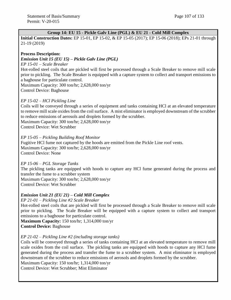
Statement of Basis/Summary Page 107 of 133
Permit: V-20-015
Group 14: EU 15 - Pickle Galv Line (PGL) & EU 21 - Cold Mill Complex
Initial Construction Dates: EP 15-01, EP 15-02, & EP 15-05 (2017); EP 15-06 (2018); EPs 21-01 through
21-19 (2019)
Process Description:
Emission Unit 15 (EU 15) – Pickle Galv Line (PGL)
EP 15-01 – Scale Breaker
Hot-rolled steel coils that are pickled will first be processed through a Scale Breaker to remove mill scale
prior to pickling. The Scale Breaker is equipped with a capture system to collect and transport emissions to
a baghouse for particulate control.
Maximum Capacity: 300 ton/hr; 2,628,000 ton/yr
Control Device: Baghouse
EP 15-02 – HCl Pickling Line
Coils will be conveyed through a series of equipment and tanks containing HCl at an elevated temperature
to remove mill scale oxides from the coil surface. A mist eliminator is employed downstream of the scrubber
to reduce emissions of aerosols and droplets formed by the scrubber.
Maximum Capacity: 300 ton/hr; 2,628,000 ton/yr
Control Device: Wet Scrubber
EP 15-05 – Pickling Building Roof Monitor
Fugitive HCl fume not captured by the hoods are emitted from the Pickle Line roof vents.
Maximum Capacity: 300 ton/hr; 2,628,000 ton/yr
Control Device: None
EP 15-06 – PGL Storage Tanks
The pickling tanks are equipped with hoods to capture any HCl fume generated during the process and
transfer the fume to a scrubber system
Maximum Capacity: 300 ton/hr; 2,628,000 ton/yr
Control Device: Wet Scrubber
Emission Unit 21 (EU 21) – Cold Mill Complex
EP 21-01 – Pickling Line #2 Scale Breaker
Hot-rolled steel coils that are pickled will first be processed through a Scale Breaker to remove mill scale
prior to pickling. The Scale Breaker will be equipped with a capture system to collect and transport
emissions to a baghouse for particulate control.
Maximum Capacity: 150 ton/hr; 1,314,000 ton/yr
Control Device: Baghouse
EP 21-02 – Pickling Line #2 (including storage tanks)
Coils will be conveyed through a series of tanks containing HCl at an elevated temperature to remove mill
scale oxides from the coil surface. The pickling tanks are equipped with hoods to capture any HCl fume
generated during the process and transfer the fume to a scrubber system. A mist eliminator is employed
downstream of the scrubber to reduce emissions of aerosols and droplets formed by the scrubber.
Maximum Capacity: 150 ton/hr; 1,314,000 ton/yr
Control Device: Wet Scrubber; Mist Eliminator
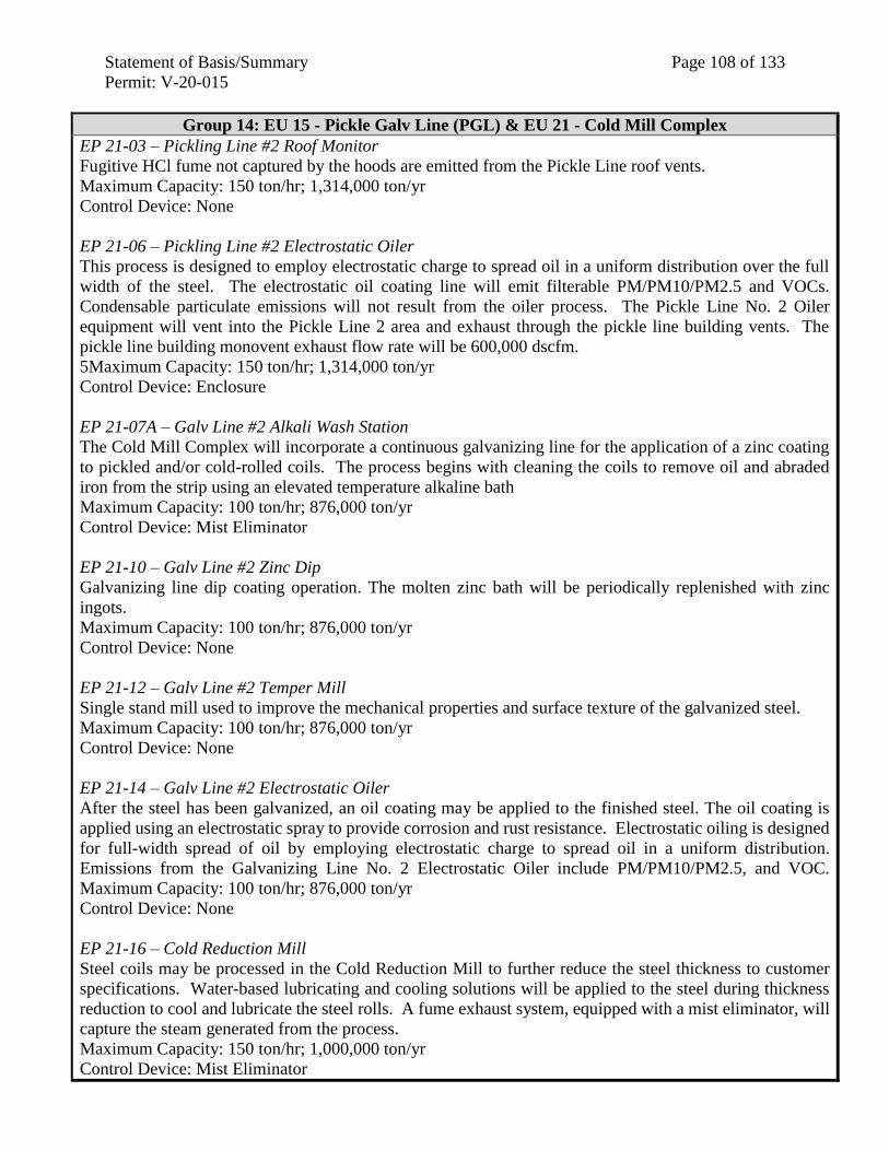
Statement of Basis/Summary Page 108 of 133
Permit: V-20-015
Group 14: EU 15 - Pickle Galv Line (PGL) & EU 21 - Cold Mill Complex
EP 21-03 – Pickling Line #2 Roof Monitor
Fugitive HCl fume not captured by the hoods are emitted from the Pickle Line roof vents.
Maximum Capacity: 150 ton/hr; 1,314,000 ton/yr
Control Device: None
EP 21-06 – Pickling Line #2 Electrostatic Oiler
This process is designed to employ electrostatic charge to spread oil in a uniform distribution over the full
width of the steel. The electrostatic oil coating line will emit filterable PM/PM10/PM2.5 and VOCs.
Condensable particulate emissions will not result from the oiler process. The Pickle Line No. 2 Oiler
equipment will vent into the Pickle Line 2 area and exhaust through the pickle line building vents. The
pickle line building monovent exhaust flow rate will be 600,000 dscfm.
5Maximum Capacity: 150 ton/hr; 1,314,000 ton/yr
Control Device: Enclosure
EP 21-07A – Galv Line #2 Alkali Wash Station
The Cold Mill Complex will incorporate a continuous galvanizing line for the application of a zinc coating
to pickled and/or cold-rolled coils. The process begins with cleaning the coils to remove oil and abraded
iron from the strip using an elevated temperature alkaline bath
Maximum Capacity: 100 ton/hr; 876,000 ton/yr
Control Device: Mist Eliminator
EP 21-10 – Galv Line #2 Zinc Dip
Galvanizing line dip coating operation. The molten zinc bath will be periodically replenished with zinc
ingots.
Maximum Capacity: 100 ton/hr; 876,000 ton/yr
Control Device: None
EP 21-12 – Galv Line #2 Temper Mill
Single stand mill used to improve the mechanical properties and surface texture of the galvanized steel.
Maximum Capacity: 100 ton/hr; 876,000 ton/yr
Control Device: None
EP 21-14 – Galv Line #2 Electrostatic Oiler
After the steel has been galvanized, an oil coating may be applied to the finished steel. The oil coating is
applied using an electrostatic spray to provide corrosion and rust resistance. Electrostatic oiling is designed
for full-width spread of oil by employing electrostatic charge to spread oil in a uniform distribution.
Emissions from the Galvanizing Line No. 2 Electrostatic Oiler include PM/PM10/PM2.5, and VOC.
Maximum Capacity: 100 ton/hr; 876,000 ton/yr
Control Device: None
EP 21-16 – Cold Reduction Mill
Steel coils may be processed in the Cold Reduction Mill to further reduce the steel thickness to customer
specifications. Water-based lubricating and cooling solutions will be applied to the steel during thickness
reduction to cool and lubricate the steel rolls. A fume exhaust system, equipped with a mist eliminator, will
capture the steam generated from the process.
Maximum Capacity: 150 ton/hr; 1,000,000 ton/yr
Control Device: Mist Eliminator
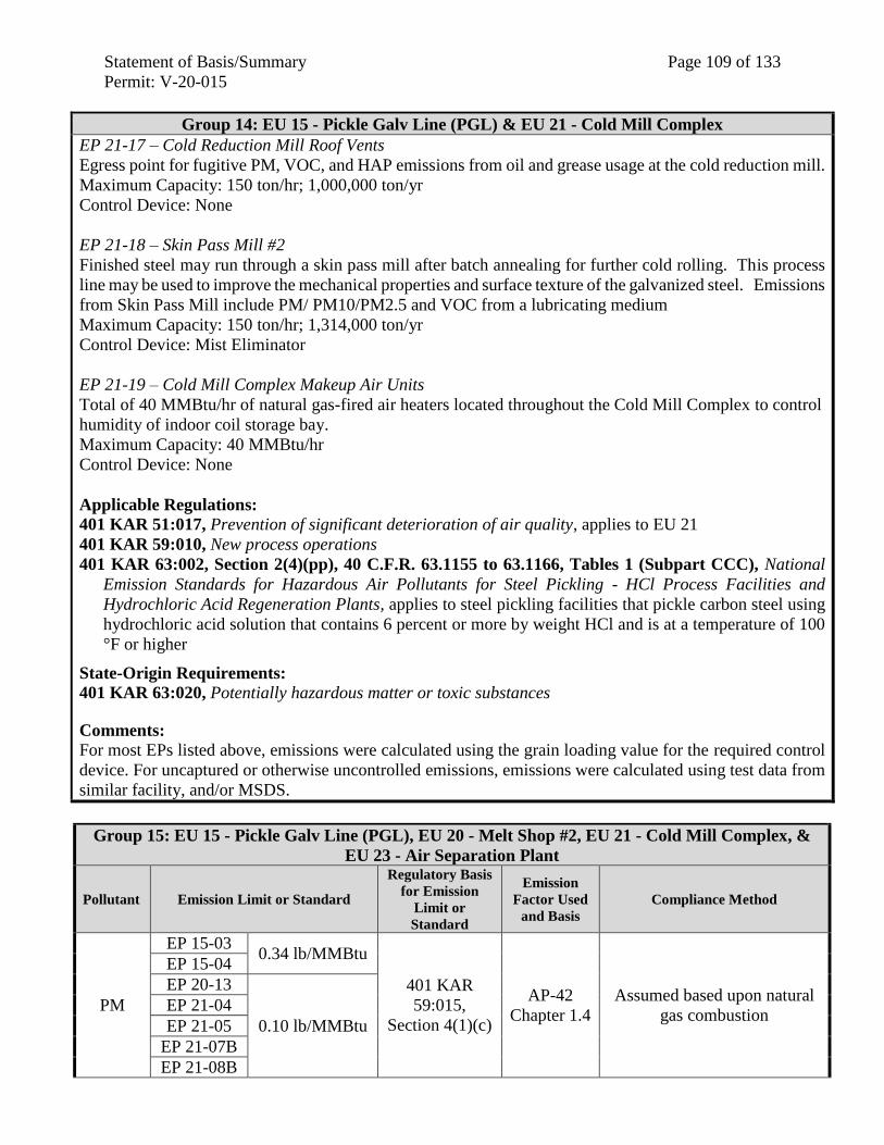
Statement of Basis/Summary Page 109 of 133
Permit: V-20-015
Group 14: EU 15 - Pickle Galv Line (PGL) & EU 21 - Cold Mill Complex
EP 21-17 – Cold Reduction Mill Roof Vents
Egress point for fugitive PM, VOC, and HAP emissions from oil and grease usage at the cold reduction mill.
Maximum Capacity: 150 ton/hr; 1,000,000 ton/yr
Control Device: None
EP 21-18 – Skin Pass Mill #2
Finished steel may run through a skin pass mill after batch annealing for further cold rolling. This process
line may be used to improve the mechanical properties and surface texture of the galvanized steel. Emissions
from Skin Pass Mill include PM/ PM10/PM2.5 and VOC from a lubricating medium
Maximum Capacity: 150 ton/hr; 1,314,000 ton/yr
Control Device: Mist Eliminator
EP 21-19 – Cold Mill Complex Makeup Air Units
Total of 40 MMBtu/hr of natural gas-fired air heaters located throughout the Cold Mill Complex to control
humidity of indoor coil storage bay.
Maximum Capacity: 40 MMBtu/hr
Control Device: None
Applicable Regulations:
401 KAR 51:017, Prevention of significant deterioration of air quality, applies to EU 21
401 KAR 59:010, New process operations
401 KAR 63:002, Section 2(4)(pp), 40 C.F.R. 63.1155 to 63.1166, Tables 1 (Subpart CCC), National
Emission Standards for Hazardous Air Pollutants for Steel Pickling - HCl Process Facilities and
Hydrochloric Acid Regeneration Plants, applies to steel pickling facilities that pickle carbon steel using
hydrochloric acid solution that contains 6 percent or more by weight HCl and is at a temperature of 100
°F or higher
State-Origin Requirements:
401 KAR 63:020, Potentially hazardous matter or toxic substances
Comments: For most EPs listed above, emissions were calculated using the grain loading value for the required control
device. For uncaptured or otherwise uncontrolled emissions, emissions were calculated using test data from
similar facility, and/or MSDS.
Group 15: EU 15 - Pickle Galv Line (PGL), EU 20 - Melt Shop #2, EU 21 - Cold Mill Complex, &
EU 23 - Air Separation Plant
Pollutant Emission Limit or Standard
Regulatory Basis
for Emission
Limit or
Standard
Emission
Factor Used
and Basis
Compliance Method
PM
EP 15-03 0.34 lb/MMBtu
401 KAR
59:015,
Section 4(1)(c)
AP-42
Chapter 1.4
Assumed based upon natural
gas combustion
EP 15-04
EP 20-13
0.10 lb/MMBtu
EP 21-04
EP 21-05
EP 21-07B
EP 21-08B
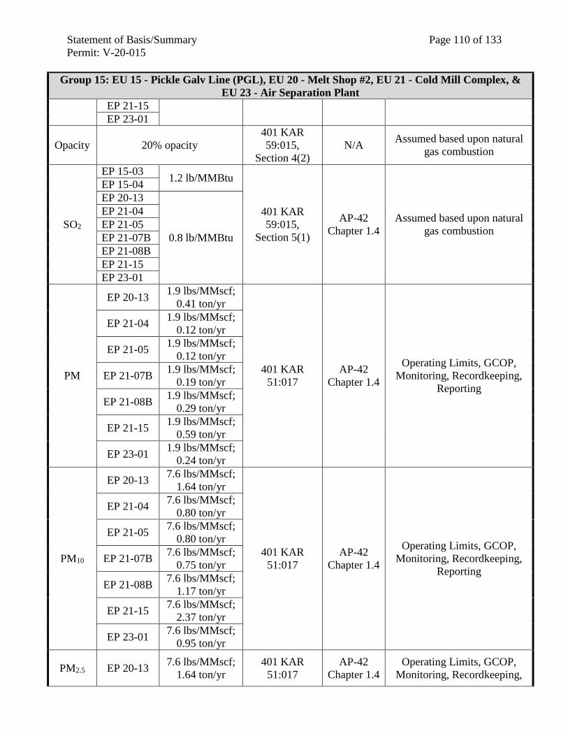
Statement of Basis/Summary Page 110 of 133
Permit: V-20-015
Group 15: EU 15 - Pickle Galv Line (PGL), EU 20 - Melt Shop #2, EU 21 - Cold Mill Complex, &
EU 23 - Air Separation Plant
EP 21-15
EP 23-01
Opacity 20% opacity
401 KAR
59:015,
Section 4(2)
N/A Assumed based upon natural
gas combustion
SO2
EP 15-03 1.2 lb/MMBtu
401 KAR
59:015,
Section 5(1)
AP-42
Chapter 1.4
Assumed based upon natural
gas combustion
EP 15-04
EP 20-13
0.8 lb/MMBtu
EP 21-04
EP 21-05
EP 21-07B
EP 21-08B
EP 21-15
EP 23-01
PM
EP 20-13 1.9 lbs/MMscf;
0.41 ton/yr
401 KAR
51:017
AP-42
Chapter 1.4
Operating Limits, GCOP,
Monitoring, Recordkeeping,
Reporting
EP 21-04 1.9 lbs/MMscf;
0.12 ton/yr
EP 21-05 1.9 lbs/MMscf;
0.12 ton/yr
EP 21-07B 1.9 lbs/MMscf;
0.19 ton/yr
EP 21-08B 1.9 lbs/MMscf;
0.29 ton/yr
EP 21-15 1.9 lbs/MMscf;
0.59 ton/yr
EP 23-01 1.9 lbs/MMscf;
0.24 ton/yr
PM10
EP 20-13 7.6 lbs/MMscf;
1.64 ton/yr
401 KAR
51:017
AP-42
Chapter 1.4
Operating Limits, GCOP,
Monitoring, Recordkeeping,
Reporting
EP 21-04 7.6 lbs/MMscf;
0.80 ton/yr
EP 21-05 7.6 lbs/MMscf;
0.80 ton/yr
EP 21-07B 7.6 lbs/MMscf;
0.75 ton/yr
EP 21-08B 7.6 lbs/MMscf;
1.17 ton/yr
EP 21-15 7.6 lbs/MMscf;
2.37 ton/yr
EP 23-01 7.6 lbs/MMscf;
0.95 ton/yr
PM2.5 EP 20-13 7.6 lbs/MMscf;
1.64 ton/yr
401 KAR
51:017
AP-42
Chapter 1.4
Operating Limits, GCOP,
Monitoring, Recordkeeping,
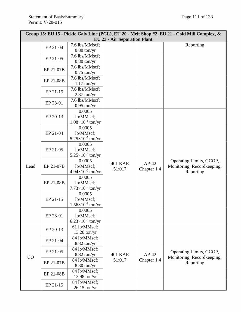
Statement of Basis/Summary Page 111 of 133
Permit: V-20-015
Group 15: EU 15 - Pickle Galv Line (PGL), EU 20 - Melt Shop #2, EU 21 - Cold Mill Complex, &
EU 23 - Air Separation Plant
EP 21-04 7.6 lbs/MMscf;
0.80 ton/yr
Reporting
EP 21-05 7.6 lbs/MMscf;
0.80 ton/yr
EP 21-07B 7.6 lbs/MMscf;
0.75 ton/yr
EP 21-08B 7.6 lbs/MMscf;
1.17 ton/yr
EP 21-15 7.6 lbs/MMscf;
2.37 ton/yr
EP 23-01 7.6 lbs/MMscf;
0.95 ton/yr
Lead
EP 20-13
0.0005
lb/MMscf;
1.08×10⁻⁴ ton/yr
401 KAR
51:017
AP-42
Chapter 1.4
Operating Limits, GCOP,
Monitoring, Recordkeeping,
Reporting
EP 21-04
0.0005
lb/MMscf;
5.25×10⁻⁵ ton/yr
EP 21-05
0.0005
lb/MMscf;
5.25×10⁻⁵ ton/yr
EP 21-07B
0.0005
lb/MMscf;
4.94×10⁻⁵ ton/yr
EP 21-08B
0.0005
lb/MMscf;
7.73×10⁻⁵ ton/yr
EP 21-15
0.0005
lb/MMscf;
1.56×10⁻⁴ ton/yr
EP 23-01
0.0005
lb/MMscf;
6.23×10⁻⁵ ton/yr
CO
EP 20-13 61 lb/MMscf;
13.20 ton/yr
401 KAR
51:017
AP-42
Chapter 1.4
Operating Limits, GCOP,
Monitoring, Recordkeeping,
Reporting
EP 21-04 84 lb/MMscf;
8.82 ton/yr
EP 21-05 84 lb/MMscf;
8.82 ton/yr
EP 21-07B 84 lb/MMscf;
8.30 ton/yr
EP 21-08B 84 lb/MMscf;
12.98 ton/yr
EP 21-15 84 lb/MMscf;
26.15 ton/yr
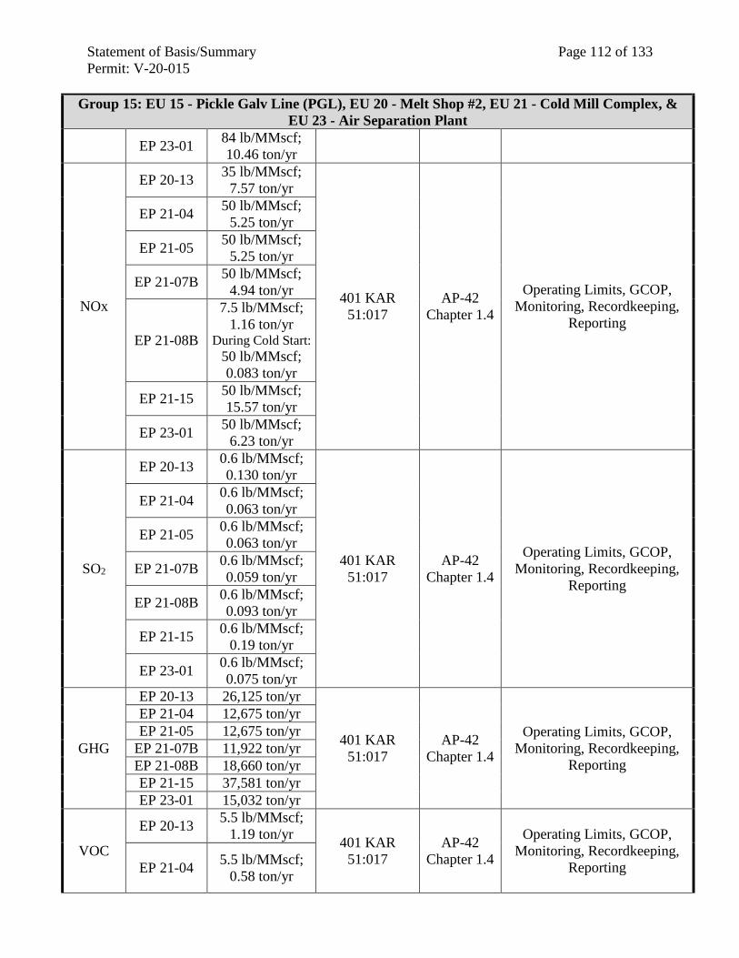
Statement of Basis/Summary Page 112 of 133
Permit: V-20-015
Group 15: EU 15 - Pickle Galv Line (PGL), EU 20 - Melt Shop #2, EU 21 - Cold Mill Complex, &
EU 23 - Air Separation Plant
EP 23-01 84 lb/MMscf;
10.46 ton/yr
NOx
EP 20-13 35 lb/MMscf;
7.57 ton/yr
401 KAR
51:017
AP-42
Chapter 1.4
Operating Limits, GCOP,
Monitoring, Recordkeeping,
Reporting
EP 21-04 50 lb/MMscf;
5.25 ton/yr
EP 21-05 50 lb/MMscf;
5.25 ton/yr
EP 21-07B 50 lb/MMscf;
4.94 ton/yr
EP 21-08B
7.5 lb/MMscf;
1.16 ton/yr During Cold Start:
50 lb/MMscf;
0.083 ton/yr
EP 21-15 50 lb/MMscf;
15.57 ton/yr
EP 23-01 50 lb/MMscf;
6.23 ton/yr
SO2
EP 20-13 0.6 lb/MMscf;
0.130 ton/yr
401 KAR
51:017
AP-42
Chapter 1.4
Operating Limits, GCOP,
Monitoring, Recordkeeping,
Reporting
EP 21-04 0.6 lb/MMscf;
0.063 ton/yr
EP 21-05 0.6 lb/MMscf;
0.063 ton/yr
EP 21-07B 0.6 lb/MMscf;
0.059 ton/yr
EP 21-08B 0.6 lb/MMscf;
0.093 ton/yr
EP 21-15 0.6 lb/MMscf;
0.19 ton/yr
EP 23-01 0.6 lb/MMscf;
0.075 ton/yr
GHG
EP 20-13 26,125 ton/yr
401 KAR
51:017
AP-42
Chapter 1.4
Operating Limits, GCOP,
Monitoring, Recordkeeping,
Reporting
EP 21-04 12,675 ton/yr
EP 21-05 12,675 ton/yr
EP 21-07B 11,922 ton/yr
EP 21-08B 18,660 ton/yr
EP 21-15 37,581 ton/yr
EP 23-01 15,032 ton/yr
VOC
EP 20-13 5.5 lb/MMscf;
1.19 ton/yr 401 KAR
51:017
AP-42
Chapter 1.4
Operating Limits, GCOP,
Monitoring, Recordkeeping,
Reporting EP 21-04 5.5 lb/MMscf;
0.58 ton/yr
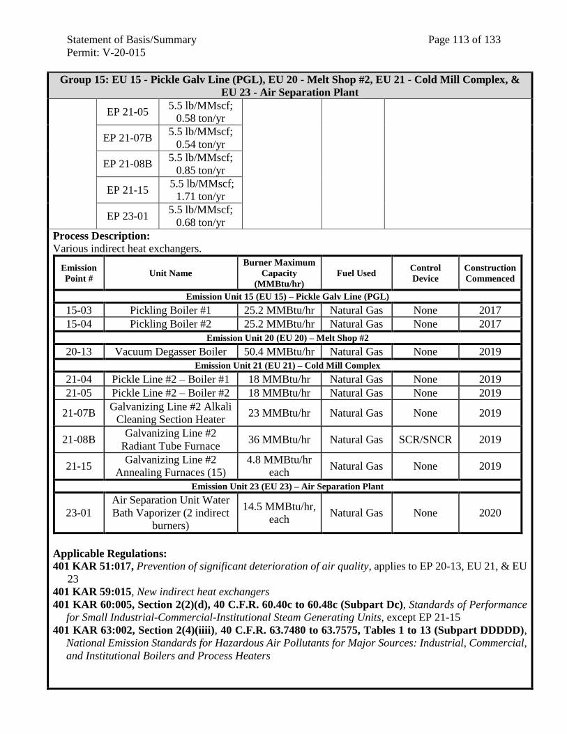
Statement of Basis/Summary Page 113 of 133
Permit: V-20-015
Group 15: EU 15 - Pickle Galv Line (PGL), EU 20 - Melt Shop #2, EU 21 - Cold Mill Complex, &
EU 23 - Air Separation Plant
EP 21-05 5.5 lb/MMscf;
0.58 ton/yr
EP 21-07B 5.5 lb/MMscf;
0.54 ton/yr
EP 21-08B 5.5 lb/MMscf;
0.85 ton/yr
EP 21-15 5.5 lb/MMscf;
1.71 ton/yr
EP 23-01 5.5 lb/MMscf;
0.68 ton/yr
Process Description:
Various indirect heat exchangers.
Emission
Point # Unit Name
Burner Maximum
Capacity
(MMBtu/hr)
Fuel Used Control
Device
Construction
Commenced
Emission Unit 15 (EU 15) – Pickle Galv Line (PGL)
15-03 Pickling Boiler #1 25.2 MMBtu/hr Natural Gas None 2017
15-04 Pickling Boiler #2 25.2 MMBtu/hr Natural Gas None 2017
Emission Unit 20 (EU 20) – Melt Shop #2
20-13 Vacuum Degasser Boiler 50.4 MMBtu/hr Natural Gas None 2019
Emission Unit 21 (EU 21) – Cold Mill Complex
21-04 Pickle Line #2 – Boiler #1 18 MMBtu/hr Natural Gas None 2019
21-05 Pickle Line #2 – Boiler #2 18 MMBtu/hr Natural Gas None 2019
21-07B Galvanizing Line #2 Alkali
Cleaning Section Heater 23 MMBtu/hr Natural Gas None 2019
21-08B Galvanizing Line #2
Radiant Tube Furnace 36 MMBtu/hr Natural Gas SCR/SNCR 2019
21-15 Galvanizing Line #2
Annealing Furnaces (15)
4.8 MMBtu/hr
each Natural Gas None 2019
Emission Unit 23 (EU 23) – Air Separation Plant
23-01
Air Separation Unit Water
Bath Vaporizer (2 indirect
burners)
14.5 MMBtu/hr,
each Natural Gas None 2020
Applicable Regulations:
401 KAR 51:017, Prevention of significant deterioration of air quality, applies to EP 20-13, EU 21, & EU
23
401 KAR 59:015, New indirect heat exchangers
401 KAR 60:005, Section 2(2)(d), 40 C.F.R. 60.40c to 60.48c (Subpart Dc), Standards of Performance
for Small Industrial-Commercial-Institutional Steam Generating Units, except EP 21-15
401 KAR 63:002, Section 2(4)(iiii), 40 C.F.R. 63.7480 to 63.7575, Tables 1 to 13 (Subpart DDDDD),
National Emission Standards for Hazardous Air Pollutants for Major Sources: Industrial, Commercial,
and Institutional Boilers and Process Heaters
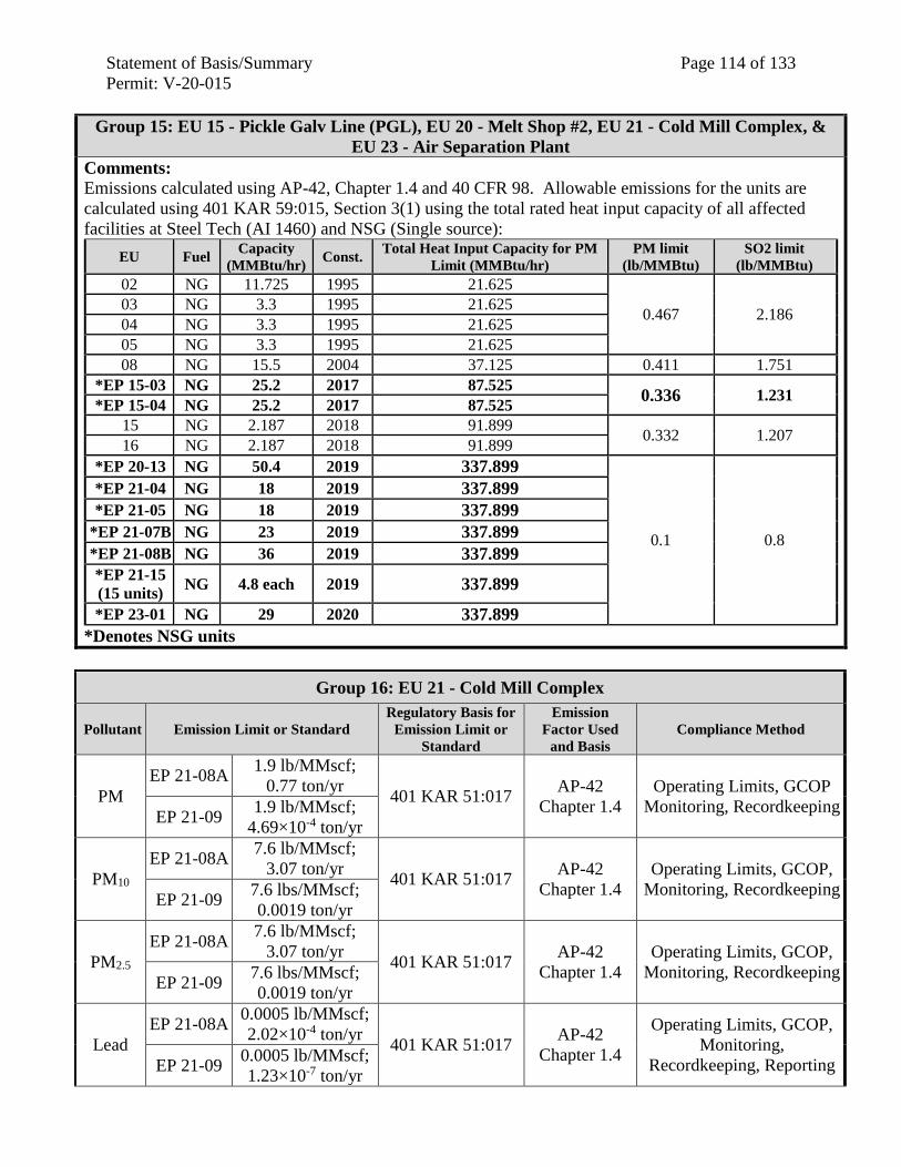
Statement of Basis/Summary Page 114 of 133
Permit: V-20-015
Group 15: EU 15 - Pickle Galv Line (PGL), EU 20 - Melt Shop #2, EU 21 - Cold Mill Complex, &
EU 23 - Air Separation Plant
Comments: Emissions calculated using AP-42, Chapter 1.4 and 40 CFR 98. Allowable emissions for the units are
calculated using 401 KAR 59:015, Section 3(1) using the total rated heat input capacity of all affected
facilities at Steel Tech (AI 1460) and NSG (Single source):
EU Fuel Capacity
(MMBtu/hr) Const.
Total Heat Input Capacity for PM
Limit (MMBtu/hr)
PM limit
(lb/MMBtu)
SO2 limit
(lb/MMBtu)
02 NG 11.725 1995 21.625
0.467 2.186 03 NG 3.3 1995 21.625
04 NG 3.3 1995 21.625
05 NG 3.3 1995 21.625
08 NG 15.5 2004 37.125 0.411 1.751
*EP 15-03 NG 25.2 2017 87.525 0.336 1.231
*EP 15-04 NG 25.2 2017 87.525
15 NG 2.187 2018 91.899 0.332 1.207
16 NG 2.187 2018 91.899
*EP 20-13 NG 50.4 2019 337.899
0.1 0.8
*EP 21-04 NG 18 2019 337.899
*EP 21-05 NG 18 2019 337.899
*EP 21-07B NG 23 2019 337.899
*EP 21-08B NG 36 2019 337.899
*EP 21-15
(15 units) NG 4.8 each 2019 337.899
*EP 23-01 NG 29 2020 337.899
*Denotes NSG units
Group 16: EU 21 - Cold Mill Complex
Pollutant Emission Limit or Standard
Regulatory Basis for
Emission Limit or
Standard
Emission
Factor Used
and Basis
Compliance Method
PM
EP 21-08A 1.9 lb/MMscf;
0.77 ton/yr 401 KAR 51:017
AP-42
Chapter 1.4
Operating Limits, GCOP
Monitoring, Recordkeeping EP 21-09
1.9 lb/MMscf;
4.69×10⁻⁴ ton/yr
PM10
EP 21-08A 7.6 lb/MMscf;
3.07 ton/yr 401 KAR 51:017
AP-42
Chapter 1.4
Operating Limits, GCOP,
Monitoring, Recordkeeping EP 21-09
7.6 lbs/MMscf;
0.0019 ton/yr
PM2.5
EP 21-08A 7.6 lb/MMscf;
3.07 ton/yr 401 KAR 51:017
AP-42
Chapter 1.4
Operating Limits, GCOP,
Monitoring, Recordkeeping EP 21-09
7.6 lbs/MMscf;
0.0019 ton/yr
Lead
EP 21-08A 0.0005 lb/MMscf;
2.02×10⁻⁴ ton/yr 401 KAR 51:017
AP-42
Chapter 1.4
Operating Limits, GCOP,
Monitoring,
Recordkeeping, Reporting EP 21-09 0.0005 lb/MMscf;
1.23×10⁻⁷ ton/yr
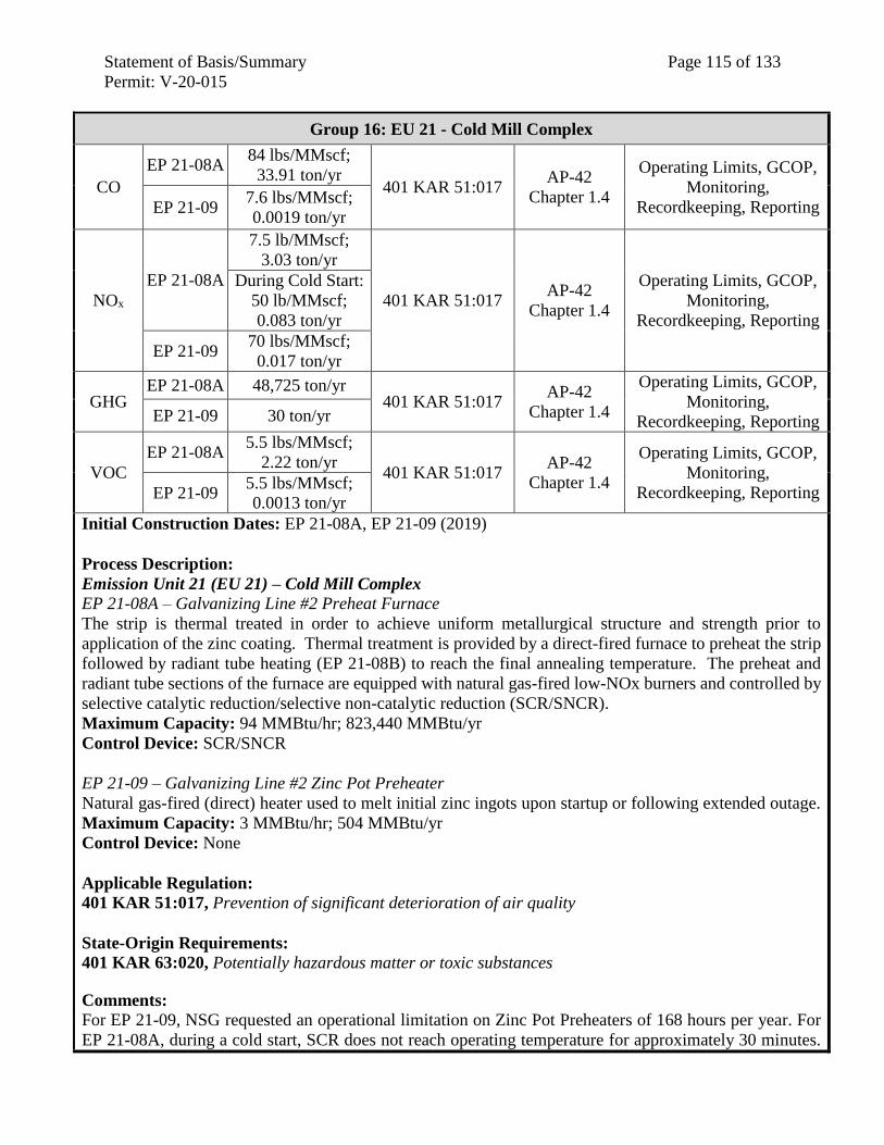
Statement of Basis/Summary Page 115 of 133
Permit: V-20-015
Group 16: EU 21 - Cold Mill Complex
CO
EP 21-08A 84 lbs/MMscf;
33.91 ton/yr 401 KAR 51:017
AP-42
Chapter 1.4
Operating Limits, GCOP,
Monitoring,
Recordkeeping, Reporting EP 21-09 7.6 lbs/MMscf;
0.0019 ton/yr
NOx
EP 21-08A
7.5 lb/MMscf;
3.03 ton/yr
401 KAR 51:017 AP-42
Chapter 1.4
Operating Limits, GCOP,
Monitoring,
Recordkeeping, Reporting
During Cold Start:
50 lb/MMscf;
0.083 ton/yr
EP 21-09 70 lbs/MMscf;
0.017 ton/yr
GHG EP 21-08A 48,725 ton/yr
401 KAR 51:017 AP-42
Chapter 1.4
Operating Limits, GCOP,
Monitoring,
Recordkeeping, Reporting EP 21-09 30 ton/yr
VOC
EP 21-08A 5.5 lbs/MMscf;
2.22 ton/yr 401 KAR 51:017
AP-42
Chapter 1.4
Operating Limits, GCOP,
Monitoring,
Recordkeeping, Reporting EP 21-09 5.5 lbs/MMscf;
0.0013 ton/yr
Initial Construction Dates: EP 21-08A, EP 21-09 (2019)
Process Description:
Emission Unit 21 (EU 21) – Cold Mill Complex
EP 21-08A – Galvanizing Line #2 Preheat Furnace
The strip is thermal treated in order to achieve uniform metallurgical structure and strength prior to
application of the zinc coating. Thermal treatment is provided by a direct-fired furnace to preheat the strip
followed by radiant tube heating (EP 21-08B) to reach the final annealing temperature. The preheat and
radiant tube sections of the furnace are equipped with natural gas-fired low-NOx burners and controlled by
selective catalytic reduction/selective non-catalytic reduction (SCR/SNCR).
Maximum Capacity: 94 MMBtu/hr; 823,440 MMBtu/yr
Control Device: SCR/SNCR
EP 21-09 – Galvanizing Line #2 Zinc Pot Preheater
Natural gas-fired (direct) heater used to melt initial zinc ingots upon startup or following extended outage.
Maximum Capacity: 3 MMBtu/hr; 504 MMBtu/yr
Control Device: None
Applicable Regulation:
401 KAR 51:017, Prevention of significant deterioration of air quality
State-Origin Requirements:
401 KAR 63:020, Potentially hazardous matter or toxic substances
Comments: For EP 21-09, NSG requested an operational limitation on Zinc Pot Preheaters of 168 hours per year. For
EP 21-08A, during a cold start, SCR does not reach operating temperature for approximately 30 minutes.
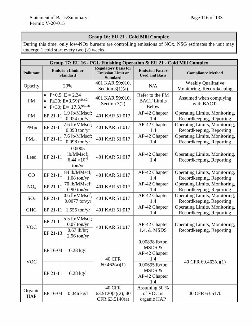
Statement of Basis/Summary Page 116 of 133
Permit: V-20-015
Group 16: EU 21 - Cold Mill Complex
During this time, only low-NOx burners are controlling emissions of NOx. NSG estimates the unit may
undergo 1 cold start every two (2) weeks.
Group 17: EU 16 - PGL Finishing Operation & EU 21 - Cold Mill Complex
Pollutant Emission Limit or
Standard
Regulatory Basis for
Emission Limit or
Standard
Emission Factor
Used and Basis Compliance Method
Opacity 20% 401 KAR 59:010,
Section 3(1)(a) N/A
Weekly Qualitative
Monitoring, Recordkeeping
PM
P<0.5; E = 2.34
P30; E=3.59𝑃0.62
P>30; E= 17.3𝑃0.16
401 KAR 59:010,
Section 3(2)
Refer to the PM
BACT Limits
Below
Assumed when complying
with BACT.
PM EP 21-11 1.9 lb/MMscf;
0.024 ton/yr 401 KAR 51:017
AP-42 Chapter
1.4
Operating Limits, Monitoring,
Recordkeeping, Reporting
PM10 EP 21-11 7.6 lb/MMscf;
0.098 ton/yr 401 KAR 51:017
AP-42 Chapter
1.4
Operating Limits, Monitoring,
Recordkeeping, Reporting
PM2.5 EP 21-11 7.6 lb/MMscf;
0.098 ton/yr 401 KAR 51:017
AP-42 Chapter
1.4
Operating Limits, Monitoring,
Recordkeeping, Reporting
Lead EP 21-11
0.0005
lb/MMscf;
6.44 ×10⁻⁶
ton/yr
401 KAR 51:017 AP-42 Chapter
1.4
Operating Limits, Monitoring,
Recordkeeping, Reporting
CO EP 21-11 84 lb/MMscf;
1.08 ton/yr 401 KAR 51:017
AP-42 Chapter
1.4
Operating Limits, Monitoring,
Recordkeeping, Reporting
NOx EP 21-11 70 lb/MMscf;
0.90 ton/yr 401 KAR 51:017
AP-42 Chapter
1.4
Operating Limits, Monitoring,
Recordkeeping, Reporting
SO2 EP 21-11 0.6 lb/MMscf;
0.0077 ton/yr 401 KAR 51:017
AP-42 Chapter
1.4
Operating Limits, Monitoring,
Recordkeeping, Reporting
GHG EP 21-11 1,555 ton/yr 401 KAR 51:017 AP-42 Chapter
1.4
Operating Limits, Monitoring,
Recordkeeping, Reporting
VOC
EP 21-11 5.5 lb/MMscf;
0.07 ton/yr 401 KAR 51:017
AP-42 Chapter
1.4. & MSDS
Operating Limits, Monitoring,
Recordkeeping, Reporting EP 21-13
0.67 lb/hr;
2.96 ton/yr
VOC
EP 16-04 0.28 kg/l
40 CFR
60.462(a)(1)
0.00838 lb/ton
MSDS &
AP-42 Chapter
1.4 40 CFR 60.463(c)(1)
EP 21-11 0.28 kg/l
0.00695 lb/ton
MSDS &
AP-42 Chapter
1.4
Organic
HAP EP 16-04 0.046 kg/l
40 CFR
63.5120(a)(2); 40
CFR 63.5140(a)
Assuming 50 %
of VOC is
organic HAP
40 CFR 63.5170
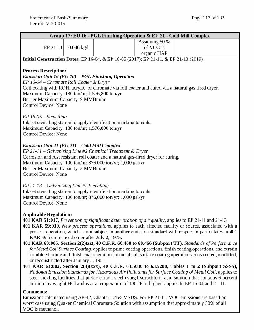
Statement of Basis/Summary Page 117 of 133
Permit: V-20-015
Group 17: EU 16 - PGL Finishing Operation & EU 21 - Cold Mill Complex
EP 21-11 0.046 kg/l
Assuming 50 %
of VOC is
organic HAP
Initial Construction Dates: EP 16-04, & EP 16-05 (2017); EP 21-11, & EP 21-13 (2019)
Process Description:
Emission Unit 16 (EU 16) – PGL Finishing Operation
EP 16-04 – Chromate Roll Coater & Dryer
Coil coating with ROH, acrylic, or chromate via roll coater and cured via a natural gas fired dryer.
Maximum Capacity: 180 ton/hr; 1,576,800 ton/yr
Burner Maximum Capacity: 9 MMBtu/hr
Control Device: None
EP 16-05 – Stenciling
Ink-jet stenciling station to apply identification marking to coils.
Maximum Capacity: 180 ton/hr; 1,576,800 ton/yr
Control Device: None
Emission Unit 21 (EU 21) – Cold Mill Complex
EP 21-11 – Galvanizing Line #2 Chemical Treatment & Dryer
Corrosion and rust resistant roll coater and a natural gas-fired dryer for curing.
Maximum Capacity: 100 ton/hr; 876,000 ton/yr; 1,000 gal/yr
Burner Maximum Capacity: 3 MMBtu/hr
Control Device: None
EP 21-13 – Galvanizing Line #2 Stenciling
Ink-jet stenciling station to apply identification marking to coils.
Maximum Capacity: 100 ton/hr; 876,000 ton/yr; 1,000 gal/yr
Control Device: None
Applicable Regulation:
401 KAR 51:017, Prevention of significant deterioration of air quality, applies to EP 21-11 and 21-13
401 KAR 59:010, New process operations, applies to each affected facility or source, associated with a
process operation, which is not subject to another emission standard with respect to particulates in 401
KAR 59, commenced on or after July 2, 1975.
401 KAR 60:005, Section 2(2)(zz), 40 C.F.R. 60.460 to 60.466 (Subpart TT), Standards of Performance
for Metal Coil Surface Coating, applies to prime coating operations, finish coating operations, and certain
combined prime and finish coat operations at metal coil surface coating operations constructed, modified,
or reconstructed after January 5, 1981.
401 KAR 63:002, Section 2(4)(xxx), 40 C.F.R. 63.5080 to 63.5200, Tables 1 to 2 (Subpart SSSS),
National Emission Standards for Hazardous Air Pollutants for Surface Coating of Metal Coil, applies to
steel pickling facilities that pickle carbon steel using hydrochloric acid solution that contains 6 percent
or more by weight HCl and is at a temperature of 100 °F or higher, applies to EP 16-04 and 21-11.
Comments: Emissions calculated using AP-42, Chapter 1.4 & MSDS. For EP 21-11, VOC emissions are based on
worst case using Quaker Chemical Chromate Solution with assumption that approximately 50% of all
VOC is methanol.
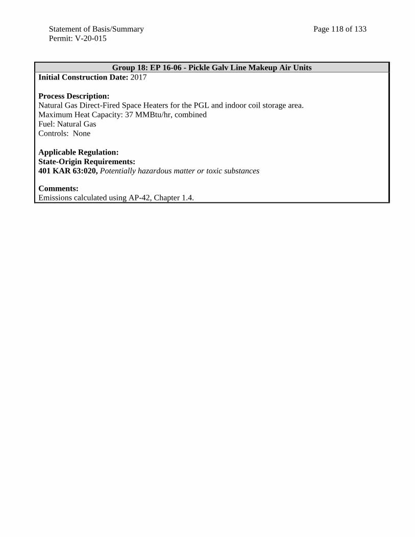
Statement of Basis/Summary Page 118 of 133
Permit: V-20-015
Group 18: EP 16-06 - Pickle Galv Line Makeup Air Units
Initial Construction Date: 2017
Process Description:
Natural Gas Direct-Fired Space Heaters for the PGL and indoor coil storage area.
Maximum Heat Capacity: 37 MMBtu/hr, combined
Fuel: Natural Gas
Controls: None
Applicable Regulation:
State-Origin Requirements:
401 KAR 63:020, Potentially hazardous matter or toxic substances
Comments: Emissions calculated using AP-42, Chapter 1.4.
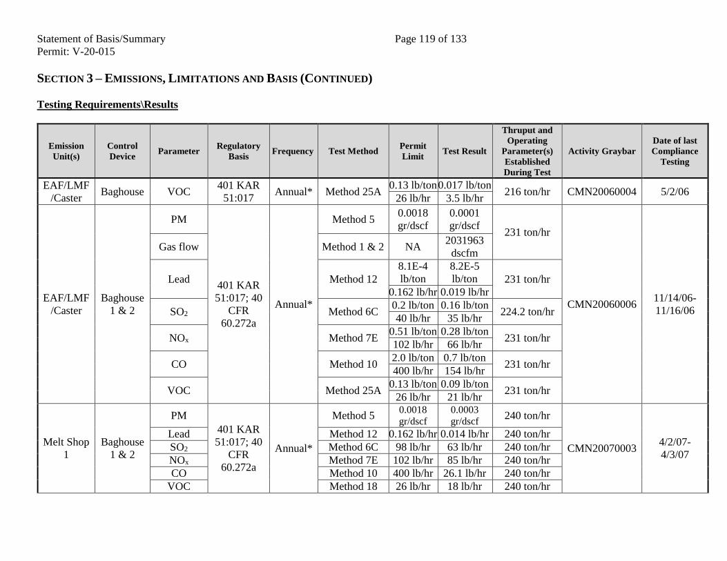
Statement of Basis/Summary Page 119 of 133
Permit: V-20-015
SECTION 3 – EMISSIONS, LIMITATIONS AND BASIS (CONTINUED)
Testing Requirements\Results
Emission
Unit(s)
Control
Device Parameter
Regulatory
Basis Frequency Test Method
Permit
Limit Test Result
Thruput and
Operating
Parameter(s)
Established
During Test
Activity Graybar
Date of last
Compliance
Testing
EAF/LMF
/Caster Baghouse VOC
401 KAR
51:017 Annual* Method 25A
0.13 lb/ton 0.017 lb/ton 216 ton/hr CMN20060004 5/2/06
26 lb/hr 3.5 lb/hr
EAF/LMF
/Caster
Baghouse
1 & 2
PM
401 KAR
51:017; 40
CFR
60.272a
Annual*
Method 5 0.0018
gr/dscf
0.0001
gr/dscf 231 ton/hr
CMN20060006 11/14/06-
11/16/06
Gas flow Method 1 & 2 NA 2031963
dscfm
Lead Method 12
8.1E-4
lb/ton
8.2E-5
lb/ton 231 ton/hr
0.162 lb/hr 0.019 lb/hr
SO2 Method 6C 0.2 lb/ton 0.16 lb/ton
224.2 ton/hr 40 lb/hr 35 lb/hr
NOx Method 7E 0.51 lb/ton 0.28 lb/ton
231 ton/hr 102 lb/hr 66 lb/hr
CO Method 10 2.0 lb/ton 0.7 lb/ton
231 ton/hr 400 lb/hr 154 lb/hr
VOC Method 25A 0.13 lb/ton 0.09 lb/ton
231 ton/hr 26 lb/hr 21 lb/hr
Melt Shop
1
Baghouse
1 & 2
PM
401 KAR
51:017; 40
CFR
60.272a
Annual*
Method 5 0.0018
gr/dscf
0.0003
gr/dscf 240 ton/hr
CMN20070003 4/2/07-
4/3/07
Lead Method 12 0.162 lb/hr 0.014 lb/hr 240 ton/hr
SO2 Method 6C 98 lb/hr 63 lb/hr 240 ton/hr
NOx Method 7E 102 lb/hr 85 lb/hr 240 ton/hr
CO Method 10 400 lb/hr 26.1 lb/hr 240 ton/hr
VOC Method 18 26 lb/hr 18 lb/hr 240 ton/hr
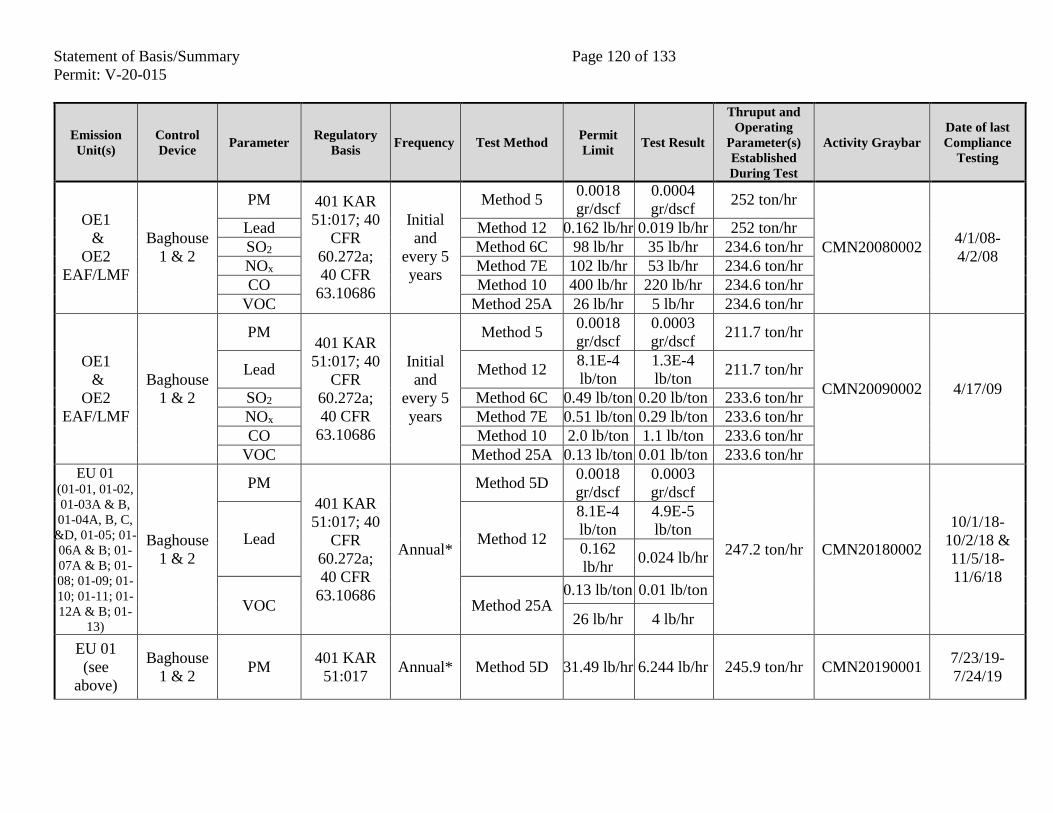
Statement of Basis/Summary Page 120 of 133
Permit: V-20-015
Emission
Unit(s)
Control
Device Parameter
Regulatory
Basis Frequency Test Method
Permit
Limit Test Result
Thruput and
Operating
Parameter(s)
Established
During Test
Activity Graybar
Date of last
Compliance
Testing
OE1
&
OE2
EAF/LMF
Baghouse
1 & 2
PM 401 KAR
51:017; 40
CFR
60.272a;
40 CFR
63.10686
Initial
and
every 5
years
Method 5 0.0018
gr/dscf
0.0004
gr/dscf 252 ton/hr
CMN20080002 4/1/08-
4/2/08
Lead Method 12 0.162 lb/hr 0.019 lb/hr 252 ton/hr
SO2 Method 6C 98 lb/hr 35 lb/hr 234.6 ton/hr
NOx Method 7E 102 lb/hr 53 lb/hr 234.6 ton/hr
CO Method 10 400 lb/hr 220 lb/hr 234.6 ton/hr
VOC Method 25A 26 lb/hr 5 lb/hr 234.6 ton/hr
OE1
&
OE2
EAF/LMF
Baghouse
1 & 2
PM 401 KAR
51:017; 40
CFR
60.272a;
40 CFR
63.10686
Initial
and
every 5
years
Method 5 0.0018
gr/dscf
0.0003
gr/dscf 211.7 ton/hr
CMN20090002 4/17/09
Lead Method 12 8.1E-4
lb/ton
1.3E-4
lb/ton 211.7 ton/hr
SO2 Method 6C 0.49 lb/ton 0.20 lb/ton 233.6 ton/hr
NOx Method 7E 0.51 lb/ton 0.29 lb/ton 233.6 ton/hr
CO Method 10 2.0 lb/ton 1.1 lb/ton 233.6 ton/hr
VOC Method 25A 0.13 lb/ton 0.01 lb/ton 233.6 ton/hr EU 01
(01-01, 01-02,
01-03A & B,
01-04A, B, C,
&D, 01-05; 01-
06A & B; 01-
07A & B; 01-
08; 01-09; 01-
10; 01-11; 01-
12A & B; 01-
13)
Baghouse
1 & 2
PM
401 KAR
51:017; 40
CFR
60.272a;
40 CFR
63.10686
Annual*
Method 5D 0.0018
gr/dscf
0.0003
gr/dscf
247.2 ton/hr CMN20180002
10/1/18-
10/2/18 &
11/5/18-
11/6/18
Lead Method 12
8.1E-4
lb/ton
4.9E-5
lb/ton
0.162
lb/hr 0.024 lb/hr
VOC Method 25A 0.13 lb/ton 0.01 lb/ton
26 lb/hr 4 lb/hr
EU 01
(see
above)
Baghouse
1 & 2 PM
401 KAR
51:017 Annual* Method 5D 31.49 lb/hr 6.244 lb/hr 245.9 ton/hr CMN20190001
7/23/19-
7/24/19
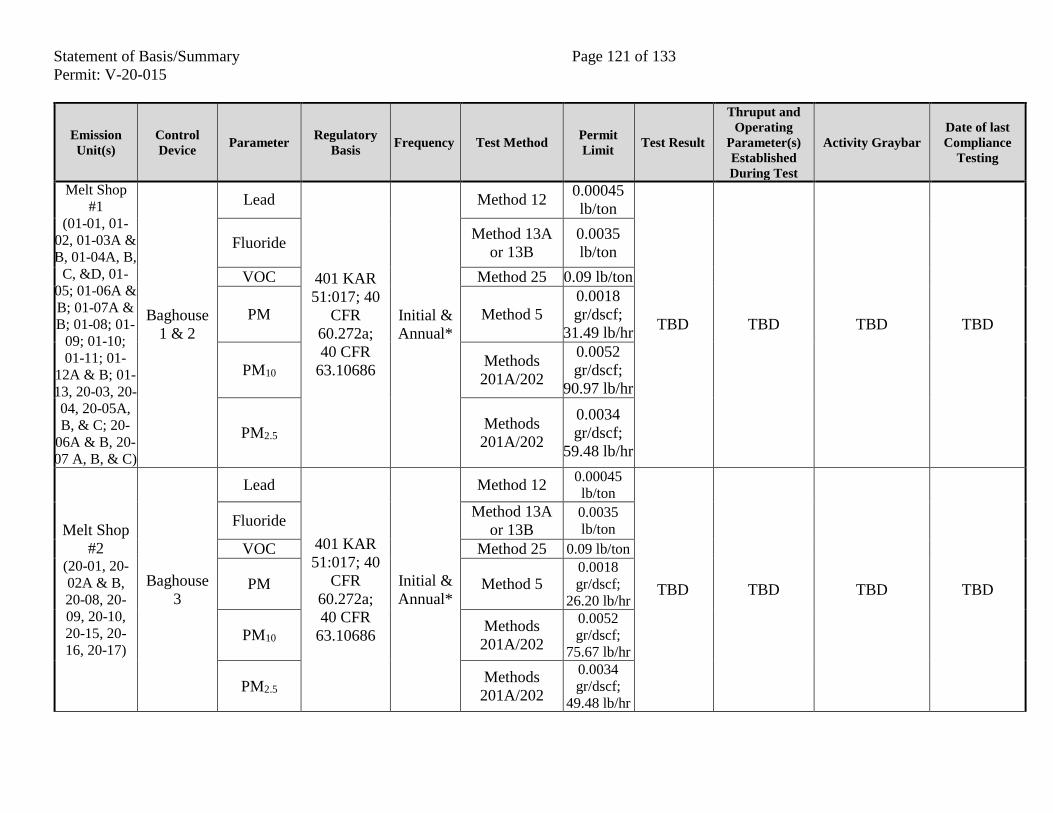
Statement of Basis/Summary Page 121 of 133
Permit: V-20-015
Emission
Unit(s)
Control
Device Parameter
Regulatory
Basis Frequency Test Method
Permit
Limit Test Result
Thruput and
Operating
Parameter(s)
Established
During Test
Activity Graybar
Date of last
Compliance
Testing
Melt Shop
#1
(01-01, 01-
02, 01-03A &
B, 01-04A, B,
C, &D, 01-
05; 01-06A &
B; 01-07A &
B; 01-08; 01-
09; 01-10;
01-11; 01-
12A & B; 01-
13, 20-03, 20-
04, 20-05A,
B, & C; 20-
06A & B, 20-
07 A, B, & C)
Baghouse
1 & 2
Lead
401 KAR
51:017; 40
CFR
60.272a;
40 CFR
63.10686
Initial &
Annual*
Method 12 0.00045
lb/ton
TBD TBD TBD TBD
Fluoride Method 13A
or 13B
0.0035
lb/ton
VOC Method 25 0.09 lb/ton
PM Method 5
0.0018
gr/dscf;
31.49 lb/hr
PM10 Methods
201A/202
0.0052
gr/dscf;
90.97 lb/hr
PM2.5 Methods
201A/202
0.0034
gr/dscf;
59.48 lb/hr
Melt Shop
#2 (20-01, 20-
02A & B,
20-08, 20-
09, 20-10,
20-15, 20-
16, 20-17)
Baghouse
3
Lead
401 KAR
51:017; 40
CFR
60.272a;
40 CFR
63.10686
Initial &
Annual*
Method 12 0.00045
lb/ton
TBD TBD TBD TBD
Fluoride Method 13A
or 13B 0.0035
lb/ton
VOC Method 25 0.09 lb/ton
PM Method 5 0.0018
gr/dscf;
26.20 lb/hr
PM10 Methods
201A/202
0.0052
gr/dscf;
75.67 lb/hr
PM2.5 Methods
201A/202
0.0034
gr/dscf;
49.48 lb/hr
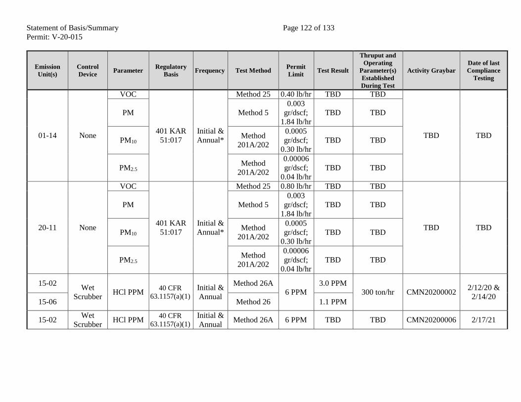
Statement of Basis/Summary Page 122 of 133
Permit: V-20-015
Emission
Unit(s)
Control
Device Parameter
Regulatory
Basis Frequency Test Method
Permit
Limit Test Result
Thruput and
Operating
Parameter(s)
Established
During Test
Activity Graybar
Date of last
Compliance
Testing
01-14 None
VOC
401 KAR
51:017
Initial &
Annual*
Method 25 0.40 lb/hr TBD TBD
TBD TBD
PM Method 5
0.003
gr/dscf;
1.84 lb/hr
TBD TBD
PM10 Method
201A/202
0.0005
gr/dscf;
0.30 lb/hr
TBD TBD
PM2.5 Method
201A/202
0.00006
gr/dscf;
0.04 lb/hr
TBD TBD
20-11 None
VOC
401 KAR
51:017
Initial &
Annual*
Method 25 0.80 lb/hr TBD TBD
TBD TBD
PM Method 5
0.003
gr/dscf;
1.84 lb/hr
TBD TBD
PM10 Method
201A/202
0.0005
gr/dscf;
0.30 lb/hr
TBD TBD
PM2.5 Method
201A/202
0.00006
gr/dscf;
0.04 lb/hr
TBD TBD
15-02 Wet
Scrubber HCl PPM
40 CFR
63.1157(a)(1)
Initial &
Annual
Method 26A 6 PPM
3.0 PPM 300 ton/hr CMN20200002
2/12/20 &
2/14/20 15-06 Method 26 1.1 PPM
15-02 Wet
Scrubber HCl PPM
40 CFR
63.1157(a)(1)
Initial &
Annual Method 26A 6 PPM TBD TBD CMN20200006 2/17/21
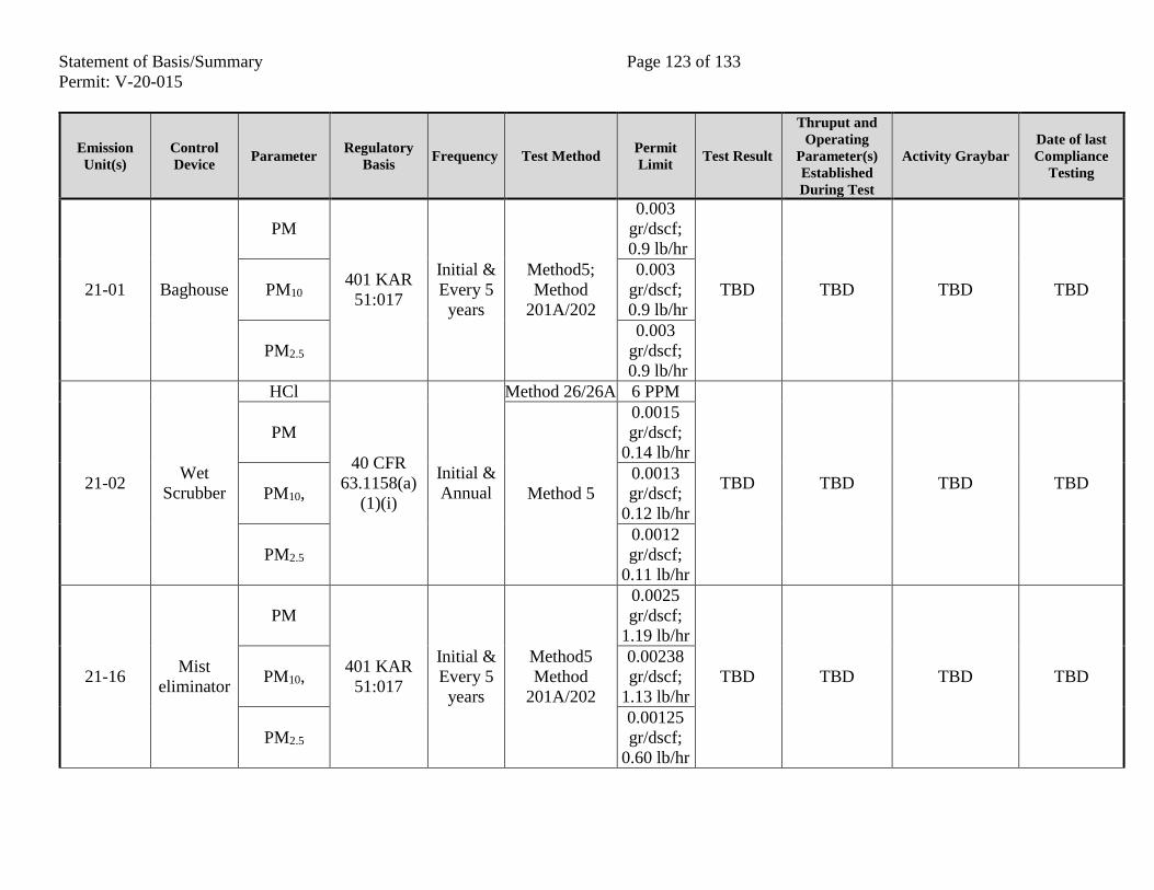
Statement of Basis/Summary Page 123 of 133
Permit: V-20-015
Emission
Unit(s)
Control
Device Parameter
Regulatory
Basis Frequency Test Method
Permit
Limit Test Result
Thruput and
Operating
Parameter(s)
Established
During Test
Activity Graybar
Date of last
Compliance
Testing
21-01 Baghouse
PM
401 KAR
51:017
Initial &
Every 5
years
Method5;
Method
201A/202
0.003
gr/dscf;
0.9 lb/hr
TBD TBD TBD TBD PM10
0.003
gr/dscf;
0.9 lb/hr
PM2.5
0.003
gr/dscf;
0.9 lb/hr
21-02 Wet
Scrubber
HCl
40 CFR
63.1158(a)
(1)(i)
Initial &
Annual
Method 26/26A 6 PPM
TBD TBD TBD TBD
PM
Method 5
0.0015
gr/dscf;
0.14 lb/hr
PM10,
0.0013
gr/dscf;
0.12 lb/hr
PM2.5
0.0012
gr/dscf;
0.11 lb/hr
21-16 Mist
eliminator
PM
401 KAR
51:017
Initial &
Every 5
years
Method5
Method
201A/202
0.0025
gr/dscf;
1.19 lb/hr
TBD TBD TBD TBD PM10,
0.00238
gr/dscf;
1.13 lb/hr
PM2.5
0.00125
gr/dscf;
0.60 lb/hr
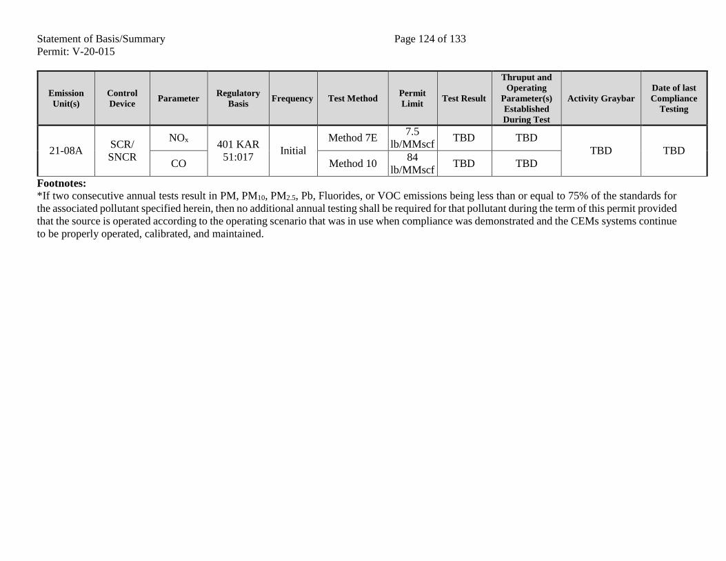
Statement of Basis/Summary Page 124 of 133
Permit: V-20-015
Emission
Unit(s)
Control
Device Parameter
Regulatory
Basis Frequency Test Method
Permit
Limit Test Result
Thruput and
Operating
Parameter(s)
Established
During Test
Activity Graybar
Date of last
Compliance
Testing
21-08A SCR/
SNCR
NOx 401 KAR
51:017 Initial
Method 7E 7.5
lb/MMscf TBD TBD
TBD TBD
CO Method 10 84
lb/MMscf TBD TBD
Footnotes:
*If two consecutive annual tests result in PM, PM10, PM2.5, Pb, Fluorides, or VOC emissions being less than or equal to 75% of the standards for
the associated pollutant specified herein, then no additional annual testing shall be required for that pollutant during the term of this permit provided
that the source is operated according to the operating scenario that was in use when compliance was demonstrated and the CEMs systems continue
to be properly operated, calibrated, and maintained.
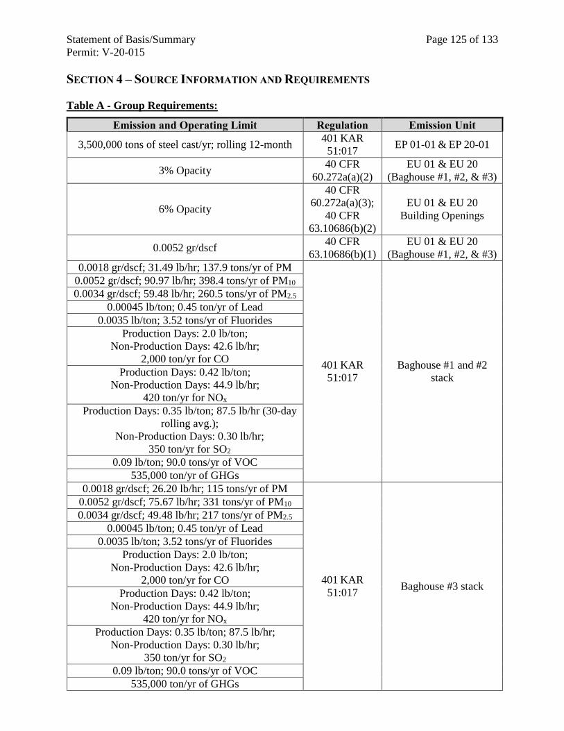
Statement of Basis/Summary Page 125 of 133
Permit: V-20-015
SECTION 4 – SOURCE INFORMATION AND REQUIREMENTS
Table A - Group Requirements:
Emission and Operating Limit Regulation Emission Unit
3,500,000 tons of steel cast/yr; rolling 12-month 401 KAR
51:017 EP 01-01 & EP 20-01
3% Opacity 40 CFR
60.272a(a)(2)
EU 01 & EU 20
(Baghouse #1, #2, & #3)
6% Opacity
40 CFR
60.272a(a)(3);
40 CFR
63.10686(b)(2)
EU 01 & EU 20
Building Openings
0.0052 gr/dscf 40 CFR
63.10686(b)(1)
EU 01 & EU 20
(Baghouse #1, #2, & #3)
0.0018 gr/dscf; 31.49 lb/hr; 137.9 tons/yr of PM
401 KAR
51:017
Baghouse #1 and #2
stack
0.0052 gr/dscf; 90.97 lb/hr; 398.4 tons/yr of PM10
0.0034 gr/dscf; 59.48 lb/hr; 260.5 tons/yr of PM2.5
0.00045 lb/ton; 0.45 ton/yr of Lead
0.0035 lb/ton; 3.52 tons/yr of Fluorides
Production Days: 2.0 lb/ton;
Non-Production Days: 42.6 lb/hr;
2,000 ton/yr for CO
Production Days: 0.42 lb/ton;
Non-Production Days: 44.9 lb/hr;
420 ton/yr for NOx
Production Days: 0.35 lb/ton; 87.5 lb/hr (30-day
rolling avg.);
Non-Production Days: 0.30 lb/hr;
350 ton/yr for SO2
0.09 lb/ton; 90.0 tons/yr of VOC
535,000 ton/yr of GHGs
0.0018 gr/dscf; 26.20 lb/hr; 115 tons/yr of PM
401 KAR
51:017 Baghouse #3 stack
0.0052 gr/dscf; 75.67 lb/hr; 331 tons/yr of PM10
0.0034 gr/dscf; 49.48 lb/hr; 217 tons/yr of PM2.5
0.00045 lb/ton; 0.45 ton/yr of Lead
0.0035 lb/ton; 3.52 tons/yr of Fluorides
Production Days: 2.0 lb/ton;
Non-Production Days: 42.6 lb/hr;
2,000 ton/yr for CO
Production Days: 0.42 lb/ton;
Non-Production Days: 44.9 lb/hr;
420 ton/yr for NOx
Production Days: 0.35 lb/ton; 87.5 lb/hr;
Non-Production Days: 0.30 lb/hr;
350 ton/yr for SO2
0.09 lb/ton; 90.0 tons/yr of VOC
535,000 ton/yr of GHGs
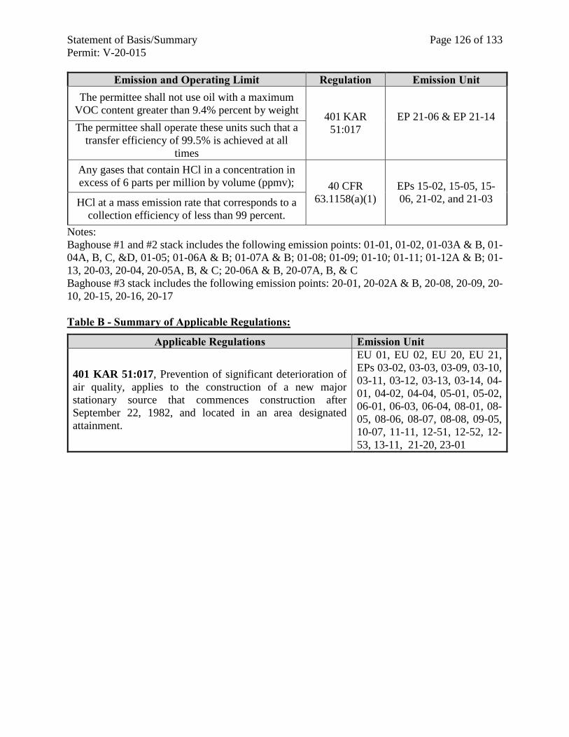
Statement of Basis/Summary Page 126 of 133
Permit: V-20-015
Emission and Operating Limit Regulation Emission Unit
The permittee shall not use oil with a maximum
VOC content greater than 9.4% percent by weight 401 KAR
51:017
EP 21-06 & EP 21-14
The permittee shall operate these units such that a
transfer efficiency of 99.5% is achieved at all
times
Any gases that contain HCl in a concentration in
excess of 6 parts per million by volume (ppmv); 40 CFR
63.1158(a)(1)
EPs 15-02, 15-05, 15-
06, 21-02, and 21-03 HCl at a mass emission rate that corresponds to a
collection efficiency of less than 99 percent.
Notes:
Baghouse #1 and #2 stack includes the following emission points: 01-01, 01-02, 01-03A & B, 01-
04A, B, C, &D, 01-05; 01-06A & B; 01-07A & B; 01-08; 01-09; 01-10; 01-11; 01-12A & B; 01-
13, 20-03, 20-04, 20-05A, B, & C; 20-06A & B, 20-07A, B, & C
Baghouse #3 stack includes the following emission points: 20-01, 20-02A & B, 20-08, 20-09, 20-
10, 20-15, 20-16, 20-17
Table B - Summary of Applicable Regulations:
Applicable Regulations Emission Unit
401 KAR 51:017, Prevention of significant deterioration of
air quality, applies to the construction of a new major
stationary source that commences construction after
September 22, 1982, and located in an area designated
attainment.
EU 01, EU 02, EU 20, EU 21,
EPs 03-02, 03-03, 03-09, 03-10,
03-11, 03-12, 03-13, 03-14, 04-
01, 04-02, 04-04, 05-01, 05-02,
06-01, 06-03, 06-04, 08-01, 08-
05, 08-06, 08-07, 08-08, 09-05,
10-07, 11-11, 12-51, 12-52, 12-
53, 13-11, 21-20, 23-01
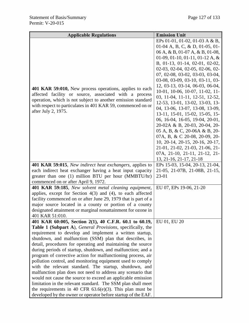
Statement of Basis/Summary Page 127 of 133
Permit: V-20-015
Applicable Regulations Emission Unit
401 KAR 59:010, New process operations, applies to each
affected facility or source, associated with a process
operation, which is not subject to another emission standard
with respect to particulates in 401 KAR 59, commenced on or
after July 2, 1975.
EPs 01-01, 01-02, 01-03 A & B,
01-04 A, B, C, & D, 01-05, 01-
06 A, & B, 01-07 A, & B, 01-08,
01-09, 01-10, 01-11, 01-12 A, &
B, 01-13, 01-14, 02-01, 02-02,
02-03, 02-04, 02-05, 02-06, 02-
07, 02-08, 03-02, 03-03, 03-04,
03-08, 03-09, 03-10, 03-11, 03-
12, 03-13, 03-14, 06-03, 06-04,
10-01, 10-06, 10-07, 11-02, 11-
03, 11-04, 11-11, 12-51, 12-52,
12-53, 13-01, 13-02, 13-03, 13-
04, 13-06, 13-07, 13-08, 13-09,
13-11, 15-01, 15-02, 15-05, 15-
06, 16-04, 16-05, 19-04, 20-01,
20-02A & B, 20-03, 20-04, 20-
05 A, B, & C, 20-06A & B, 20-
07A, B, & C 20-08, 20-09, 20-
10, 20-14, 20-15, 20-16, 20-17,
21-01, 21-02, 21-03, 21-06, 21-
07A, 21-10, 21-11, 21-12, 21-
13, 21-16, 21-17, 21-18
401 KAR 59:015, New indirect heat exchangers, applies to
each indirect heat exchanger having a heat input capacity
greater than one (1) million BTU per hour (MMBTU/hr)
commenced on or after April 9, 1972.
EPs 15-03, 15-04, 20-13, 21-04,
21-05, 21-07B, 21-08B, 21-15,
23-01
401 KAR 59:185, New solvent metal cleaning equipment,
applies, except for Section 4(3) and (4), to each affected
facility commenced on or after June 29, 1979 that is part of a
major source located in a county or portion of a county
designated attainment or marginal nonattainment for ozone in
401 KAR 51:010.
EU 07, EPs 19-06, 21-20
401 KAR 60:005, Section 2(1), 40 C.F.R. 60.1 to 60.19,
Table 1 (Subpart A), General Provisions, specifically, the
requirement to develop and implement a written startup,
shutdown, and malfunction (SSM) plan that describes, in
detail, procedures for operating and maintaining the source
during periods of startup, shutdown, and malfunction; and a
program of corrective action for malfunctioning process, air
pollution control, and monitoring equipment used to comply
with the relevant standard. The startup, shutdown, and
malfunction plan does not need to address any scenario that
would not cause the source to exceed an applicable emission
limitation in the relevant standard. The SSM plan shall meet
the requirements in 40 CFR 63.6(e)(3). This plan must be
developed by the owner or operator before startup of the EAF.
EU 01, EU 20
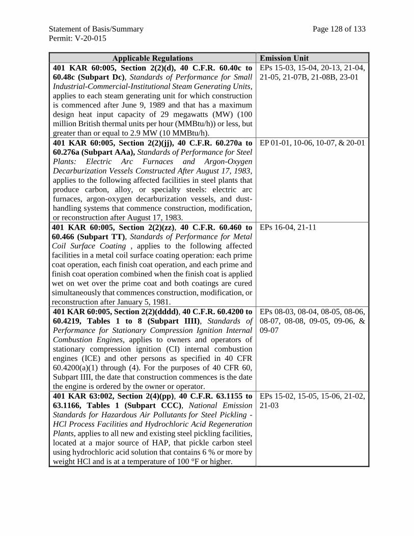
Statement of Basis/Summary Page 128 of 133
Permit: V-20-015
Applicable Regulations Emission Unit
401 KAR 60:005, Section 2(2)(d), 40 C.F.R. 60.40c to
60.48c (Subpart Dc), Standards of Performance for Small
Industrial-Commercial-Institutional Steam Generating Units,
applies to each steam generating unit for which construction
is commenced after June 9, 1989 and that has a maximum
design heat input capacity of 29 megawatts (MW) (100
million British thermal units per hour (MMBtu/h)) or less, but
greater than or equal to 2.9 MW (10 MMBtu/h).
EPs 15-03, 15-04, 20-13, 21-04,
21-05, 21-07B, 21-08B, 23-01
401 KAR 60:005, Section 2(2)(jj), 40 C.F.R. 60.270a to
60.276a (Subpart AAa), Standards of Performance for Steel
Plants: Electric Arc Furnaces and Argon-Oxygen
Decarburization Vessels Constructed After August 17, 1983,
applies to the following affected facilities in steel plants that
produce carbon, alloy, or specialty steels: electric arc
furnaces, argon-oxygen decarburization vessels, and dust-
handling systems that commence construction, modification,
or reconstruction after August 17, 1983.
EP 01-01, 10-06, 10-07, & 20-01
401 KAR 60:005, Section 2(2)(zz), 40 C.F.R. 60.460 to
60.466 (Subpart TT), Standards of Performance for Metal
Coil Surface Coating , applies to the following affected
facilities in a metal coil surface coating operation: each prime
coat operation, each finish coat operation, and each prime and
finish coat operation combined when the finish coat is applied
wet on wet over the prime coat and both coatings are cured
simultaneously that commences construction, modification, or
reconstruction after January 5, 1981.
EPs 16-04, 21-11
401 KAR 60:005, Section 2(2)(dddd), 40 C.F.R. 60.4200 to
60.4219, Tables 1 to 8 (Subpart IIII), Standards of
Performance for Stationary Compression Ignition Internal
Combustion Engines, applies to owners and operators of
stationary compression ignition (CI) internal combustion
engines (ICE) and other persons as specified in 40 CFR
60.4200(a)(1) through (4). For the purposes of 40 CFR 60,
Subpart IIII, the date that construction commences is the date
the engine is ordered by the owner or operator.
EPs 08-03, 08-04, 08-05, 08-06,
08-07, 08-08, 09-05, 09-06, &
09-07
401 KAR 63:002, Section 2(4)(pp), 40 C.F.R. 63.1155 to
63.1166, Tables 1 (Subpart CCC), National Emission
Standards for Hazardous Air Pollutants for Steel Pickling -
HCl Process Facilities and Hydrochloric Acid Regeneration
Plants, applies to all new and existing steel pickling facilities,
located at a major source of HAP, that pickle carbon steel
using hydrochloric acid solution that contains 6 % or more by
weight HCl and is at a temperature of 100 °F or higher.
EPs 15-02, 15-05, 15-06, 21-02,
21-03
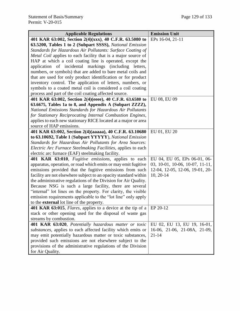
Statement of Basis/Summary Page 129 of 133
Permit: V-20-015
Applicable Regulations Emission Unit
401 KAR 63:002, Section 2(4)(xxx), 40 C.F.R. 63.5080 to
63.5200, Tables 1 to 2 (Subpart SSSS), National Emission
Standards for Hazardous Air Pollutants: Surface Coating of
Metal Coil applies to each facility that is a major source of
HAP at which a coil coating line is operated, except the
application of incidental markings (including letters,
numbers, or symbols) that are added to bare metal coils and
that are used for only product identification or for product
inventory control. The application of letters, numbers, or
symbols to a coated metal coil is considered a coil coating
process and part of the coil coating affected source.
EPs 16-04, 21-11
401 KAR 63:002, Section 2(4)(eeee), 40 C.F.R. 63.6580 to
63.6675, Tables 1a to 8, and Appendix A (Subpart ZZZZ),
National Emissions Standards for Hazardous Air Pollutants
for Stationary Reciprocating Internal Combustion Engines,
applies to each new stationary RICE located at a major or area
source of HAP emissions.
EU 08, EU 09
401 KAR 63:002, Section 2(4)(aaaaa), 40 C.F.R. 63.10680
to 63.10692, Table 1 (Subpart YYYYY), National Emission
Standards for Hazardous Air Pollutants for Area Sources:
Electric Arc Furnace Steelmaking Facilities, applies to each
electric arc furnace (EAF) steelmaking facility.
EU 01, EU 20
401 KAR 63:010, Fugitive emissions, applies to each
apparatus, operation, or road which emits or may emit fugitive
emissions provided that the fugitive emissions from such
facility are not elsewhere subject to an opacity standard within
the administrative regulations of the Division for Air Quality.
Because NSG is such a large facility, there are several
“internal” lot lines on the property. For clarity, the visible
emission requirements applicable to the “lot line” only apply
to the external lot line of the property.
EU 04, EU 05, EPs 06-01, 06-
03, 10-01, 10-06, 10-07, 11-11,
12-04, 12-05, 12-06, 19-01, 20-
10, 20-14
401 KAR 63:015, Flares, applies to a device at the tip of a
stack or other opening used for the disposal of waste gas
streams by combustion.
EP 20-12
401 KAR 63:020, Potentially hazardous matter or toxic
substances, applies to each affected facility which emits or
may emit potentially hazardous matter or toxic substances,
provided such emissions are not elsewhere subject to the
provisions of the administrative regulations of the Division
for Air Quality.
EU 02, EU 13, EU 19, 16-01,
16-06, 21-06, 21-08A, 21-09,
21-14
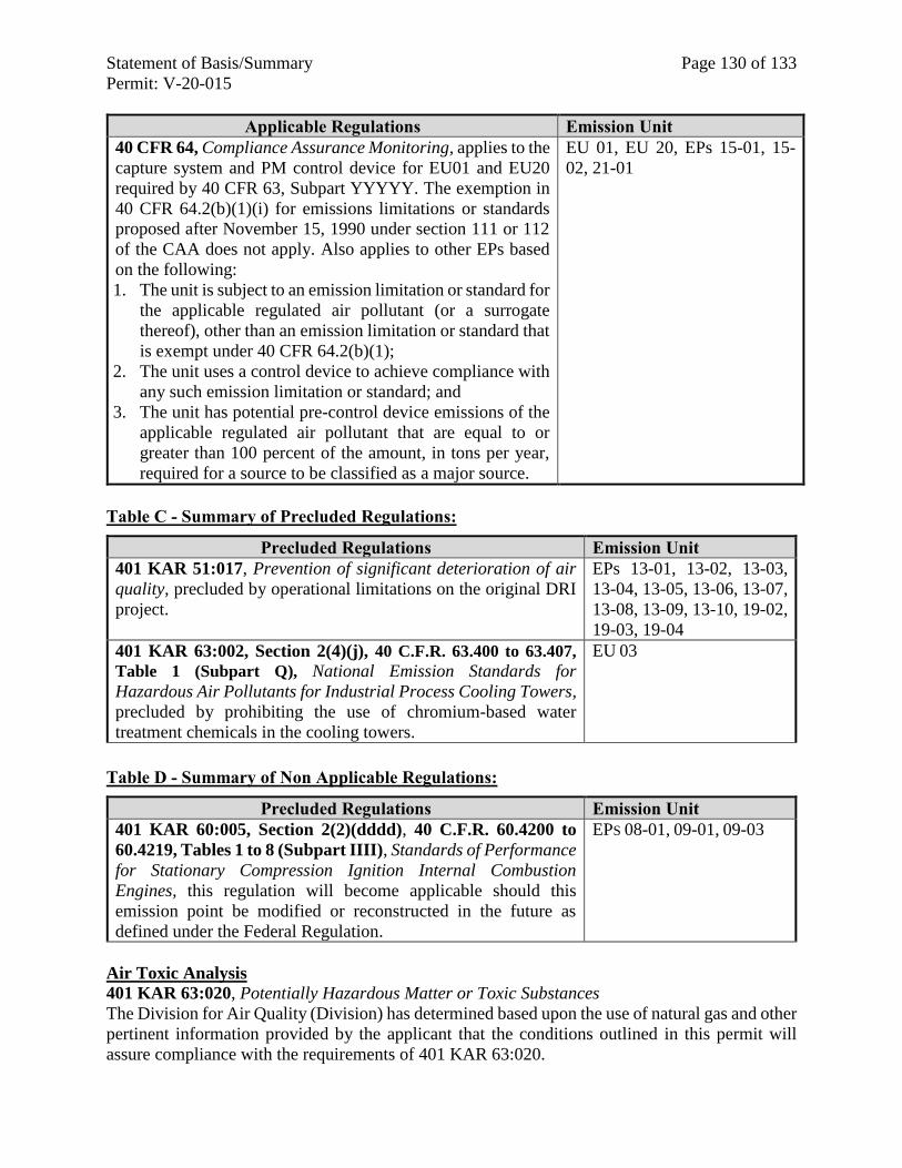
Statement of Basis/Summary Page 130 of 133
Permit: V-20-015
Applicable Regulations Emission Unit
40 CFR 64, Compliance Assurance Monitoring, applies to the
capture system and PM control device for EU01 and EU20
required by 40 CFR 63, Subpart YYYYY. The exemption in
40 CFR 64.2(b)(1)(i) for emissions limitations or standards
proposed after November 15, 1990 under section 111 or 112
of the CAA does not apply. Also applies to other EPs based
on the following:
1. The unit is subject to an emission limitation or standard for
the applicable regulated air pollutant (or a surrogate
thereof), other than an emission limitation or standard that
is exempt under 40 CFR 64.2(b)(1);
2. The unit uses a control device to achieve compliance with
any such emission limitation or standard; and
3. The unit has potential pre-control device emissions of the
applicable regulated air pollutant that are equal to or
greater than 100 percent of the amount, in tons per year,
required for a source to be classified as a major source.
EU 01, EU 20, EPs 15-01, 15-
02, 21-01
Table C - Summary of Precluded Regulations:
Precluded Regulations Emission Unit
401 KAR 51:017, Prevention of significant deterioration of air
quality, precluded by operational limitations on the original DRI
project.
EPs 13-01, 13-02, 13-03,
13-04, 13-05, 13-06, 13-07,
13-08, 13-09, 13-10, 19-02,
19-03, 19-04
401 KAR 63:002, Section 2(4)(j), 40 C.F.R. 63.400 to 63.407,
Table 1 (Subpart Q), National Emission Standards for
Hazardous Air Pollutants for Industrial Process Cooling Towers,
precluded by prohibiting the use of chromium-based water
treatment chemicals in the cooling towers.
EU 03
Table D - Summary of Non Applicable Regulations:
Precluded Regulations Emission Unit
401 KAR 60:005, Section 2(2)(dddd), 40 C.F.R. 60.4200 to
60.4219, Tables 1 to 8 (Subpart IIII), Standards of Performance
for Stationary Compression Ignition Internal Combustion
Engines, this regulation will become applicable should this
emission point be modified or reconstructed in the future as
defined under the Federal Regulation.
EPS 08-01, 09-01, 09-03
Air Toxic Analysis
401 KAR 63:020, Potentially Hazardous Matter or Toxic Substances
The Division for Air Quality (Division) has determined based upon the use of natural gas and other
pertinent information provided by the applicant that the conditions outlined in this permit will
assure compliance with the requirements of 401 KAR 63:020.
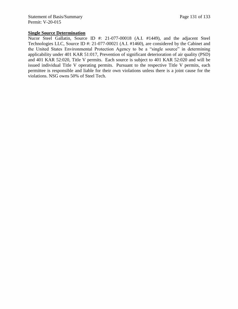
Statement of Basis/Summary Page 131 of 133
Permit: V-20-015
Single Source Determination Nucor Steel Gallatin, Source ID #: 21-077-00018 (A.I. #1449), and the adjacent Steel
Technologies LLC, Source ID #: 21-077-00021 (A.I. #1460), are considered by the Cabinet and
the United States Environmental Protection Agency to be a “single source” in determining
applicability under 401 KAR 51:017, Prevention of significant deterioration of air quality (PSD)
and 401 KAR 52:020, Title V permits. Each source is subject to 401 KAR 52:020 and will be
issued individual Title V operating permits. Pursuant to the respective Title V permits, each
permittee is responsible and liable for their own violations unless there is a joint cause for the
violations. NSG owns 50% of Steel Tech.
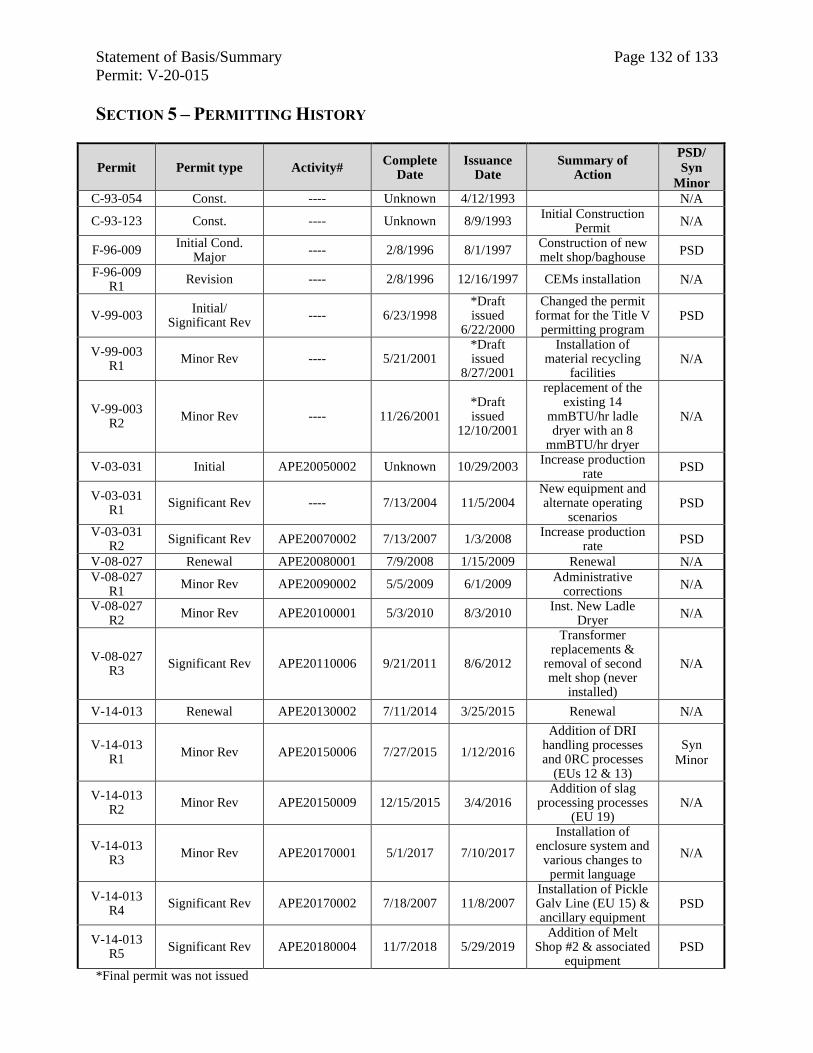
Statement of Basis/Summary Page 132 of 133
Permit: V-20-015
SECTION 5 – PERMITTING HISTORY
Permit Permit type Activity# Complete
Date Issuance
Date Summary of
Action
PSD/
Syn
Minor
C-93-054 Const. ---- Unknown 4/12/1993 N/A
C-93-123 Const. ---- Unknown 8/9/1993 Initial Construction
Permit N/A
F-96-009 Initial Cond.
Major ---- 2/8/1996 8/1/1997
Construction of new melt shop/baghouse
PSD
F-96-009 R1
Revision ---- 2/8/1996 12/16/1997 CEMs installation N/A
V-99-003 Initial/
Significant Rev ---- 6/23/1998
*Draft issued
6/22/2000
Changed the permit format for the Title V permitting program
PSD
V-99-003 R1
Minor Rev ---- 5/21/2001 *Draft issued
8/27/2001
Installation of material recycling
facilities N/A
V-99-003 R2
Minor Rev ---- 11/26/2001 *Draft issued
12/10/2001
replacement of the existing 14
mmBTU/hr ladle dryer with an 8
mmBTU/hr dryer
N/A
V-03-031 Initial APE20050002 Unknown 10/29/2003 Increase production
rate PSD
V-03-031 R1
Significant Rev ---- 7/13/2004 11/5/2004 New equipment and alternate operating
scenarios PSD
V-03-031 R2
Significant Rev APE20070002 7/13/2007 1/3/2008 Increase production
rate PSD
V-08-027 Renewal APE20080001 7/9/2008 1/15/2009 Renewal N/A
V-08-027 R1
Minor Rev APE20090002 5/5/2009 6/1/2009 Administrative
corrections N/A
V-08-027 R2
Minor Rev APE20100001 5/3/2010 8/3/2010 Inst. New Ladle
Dryer N/A
V-08-027 R3
Significant Rev APE20110006 9/21/2011 8/6/2012
Transformer replacements &
removal of second melt shop (never
installed)
N/A
V-14-013 Renewal APE20130002 7/11/2014 3/25/2015 Renewal N/A
V-14-013 R1
Minor Rev APE20150006 7/27/2015 1/12/2016
Addition of DRI handling processes and 0RC processes
(EUs 12 & 13)
Syn
Minor
V-14-013 R2
Minor Rev APE20150009 12/15/2015 3/4/2016 Addition of slag
processing processes (EU 19)
N/A
V-14-013 R3
Minor Rev APE20170001 5/1/2017 7/10/2017
Installation of enclosure system and
various changes to permit language
N/A
V-14-013 R4
Significant Rev APE20170002 7/18/2007 11/8/2007 Installation of Pickle Galv Line (EU 15) & ancillary equipment
PSD
V-14-013 R5
Significant Rev APE20180004 11/7/2018 5/29/2019 Addition of Melt
Shop #2 & associated equipment
PSD
*Final permit was not issued
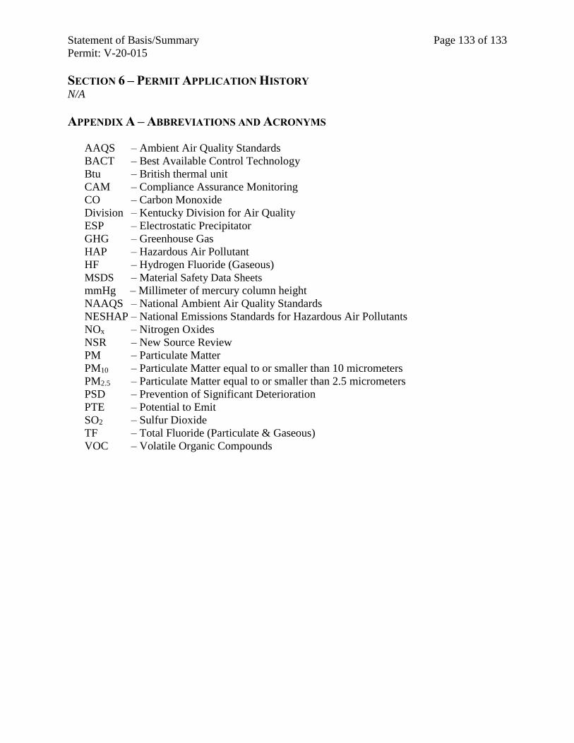
Statement of Basis/Summary Page 133 of 133
Permit: V-20-015
SECTION 6 – PERMIT APPLICATION HISTORY N/A
APPENDIX A – ABBREVIATIONS AND ACRONYMS
AAQS – Ambient Air Quality Standards
BACT – Best Available Control Technology
Btu – British thermal unit
CAM – Compliance Assurance Monitoring
CO – Carbon Monoxide
Division – Kentucky Division for Air Quality
ESP – Electrostatic Precipitator
GHG – Greenhouse Gas
HAP – Hazardous Air Pollutant
HF – Hydrogen Fluoride (Gaseous)
MSDS – Material Safety Data Sheets
mmHg – Millimeter of mercury column height
NAAQS – National Ambient Air Quality Standards
NESHAP – National Emissions Standards for Hazardous Air Pollutants
NOx – Nitrogen Oxides
NSR – New Source Review
PM – Particulate Matter
PM10 – Particulate Matter equal to or smaller than 10 micrometers
PM2.5 – Particulate Matter equal to or smaller than 2.5 micrometers
PSD – Prevention of Significant Deterioration
PTE – Potential to Emit
SO2 – Sulfur Dioxide
TF – Total Fluoride (Particulate & Gaseous)
VOC – Volatile Organic Compounds
Related Documents


