Common S60 Operator Display Data And Layout Specification 4 Owner: Function: Approver: Location: This material, including documentation and any related computer programs, is protected by copyright controlled by Nokia. All rights are reserved. Copying, including reproducing, storing, adapting or translating, any or all of this material requires the prior written consent of Nokia. This material also contains confidential information, which may not be disclosed to others without the prior written consent of Nokia. Version 4 APPROVED 24 May 2007 COMPANY CONFIDENTIAL 1 (176) Common S60 Operator Display Data And Layout Copyright © 2007 Nokia. All rights reserved. GUID-629D4CCD-2861-4F43-9261-2F1E889728BA

Welcome message from author
This document is posted to help you gain knowledge. Please leave a comment to let me know what you think about it! Share it to your friends and learn new things together.
Transcript

Common S60 Operator Display Data And LayoutSpecification
4
Owner:Function:Approver:Location:
This material, including documentation and any related computer programs, is protected by copyrightcontrolled by Nokia. All rights are reserved. Copying, including reproducing, storing, adapting or translating,any or all of this material requires the prior written consent of Nokia. This material also contains confidentialinformation, which may not be disclosed to others without the prior written consent of Nokia.
Version 4 APPROVED 24 May 2007COMPANY CONFIDENTIAL
1 (176)
Common S60 Operator Display Data And Layout Copyright © 2007 Nokia. All rights reserved.GUID-629D4CCD-2861-4F43-9261-2F1E889728BA

Contents1 General .....................................................................................................................................................................7
1.1 Disclaimer ........................................................................................................................................................71.2 Using The S60 Field Test Displays..................................................................................................................7
2 Group 01: GSM Signaling displays which can be visible to network operators ..............................................222.1 Group 01 Information...................................................................................................................................222.2 Display 01.01: Information of the serving cell...........................................................................................222.3 Display 01.02: More information of the serving cell .................................................................................232.4 Display 01.03: Information of the serving cell, 1st and 2nd neighbor....................................................242.5 Display 01.04: Information of the 3rd, 4th and 5th neighbor .................................................................262.6 Display 01.05: Information of the 6th, 7th and 8th neighbor .................................................................272.7 Display 01.06: Network selection display...................................................................................................282.8 Display 01.07: System information bits for serving cell ...........................................................................292.9 Display 01.08: Paging repeat period, TMSI, periodic location update, AFC and AGC..............................302.10 Display 01.09: Network parameters .........................................................................................................312.11 Display 01.10: Ciphering, hopping DTX status and IMSI .........................................................................312.12 Display 01.11: Uplink DTX switching display............................................................................................322.13 Display 01.12: Storing and removing BTS_TEST carrier...........................................................................332.14 Display 01.13: Toggle Cell Barred Status ..................................................................................................342.15 Display 01.14: Modify last used band .......................................................................................................352.16 Display 01.15: Equivalent PLMN display ..................................................................................................362.17 Display 01.16: Equivalent PLMN display ...................................................................................................36
3 Group 04: GSM Test Timers SMS and Call Counter Displays ...............................................................................383.1 Display 04.05: Call attempts counters.........................................................................................................383.2 Display 04.06: Information about reasons for call clearing .....................................................................38
4 Group 05: GSM Data Displays................................................................................................................................404.1 Display 05.01: HSCSD, Timeslot information display .................................................................................404.2 Display 05.02: HSCSD, Timeslot power control level display ....................................................................40
5 Group 06: GPRS Signaling displays ......................................................................................................................425.1 Group 06 Information...................................................................................................................................425.2 Display 06.01: Information of the current GPRS state and previous TBF configuration........................425.3 Display 06.02: Previous UL TBF establishment...........................................................................................435.4 Display 06.03: Information of the GMM state.............................................................................................445.5 Display 06.04: Values of P-TMSI, RAC, SMS radio priority, Ciphering and Non-DRX parameters............445.6 Display 06.05: GPRS Network parameters ..................................................................................................455.7 Display 06.06: Packet control channel parameters ...................................................................................465.8 Display 06.07: (Packet) System information parameters .........................................................................465.9 Display 06.08: Cell re-selection parameters (serving cell) ........................................................................475.10 Display 06.09: GPRS information of the serving cell, 1st, 2nd, and 3rd neighbor ...............................485.11 Display 06.10: GPRS information of 4th, 5th and 6th neighbor.............................................................495.12 Display 06.11: GPRS information of the serving cell and 6 neighbors ..................................................505.13 Display 06.12: EGPRS specific parameters ................................................................................................525.14 Display 06.14 Dual Transfer Mode information .......................................................................................535.15 Display 06.15: Dual Transfer Mode configuration ...................................................................................53
6 Group 07: GPRS Data protocol displays ...............................................................................................................546.1 Display 07.01: Information of the first active PDP context.......................................................................546.2 Display 07.02: Information of the second active PDP context .................................................................546.3 Display 07.03: Information of the RLC state...............................................................................................556.4 Display 07.04: RLC parameters ....................................................................................................................566.5 Display 07.05: RLC data block counters ......................................................................................................576.6 Display 07.06: LLC data block counters.......................................................................................................57
Version 4 APPROVED 24 May 2007COMPANY CONFIDENTIAL
2 (176)
Common S60 Operator Display Data And Layout Copyright © 2007 Nokia. All rights reserved.GUID-629D4CCD-2861-4F43-9261-2F1E889728BA

6.7 Display 07.07: LLC Ciphering parameters ...................................................................................................576.8 Display 07.08: LLC parameters of the first SAPI .........................................................................................586.9 Display 07.09: LLC parameters of the second SAPI ....................................................................................596.10 Display 07.10: SNDC Data counters ...........................................................................................................596.11 Display 07.11: PPP information.................................................................................................................606.12 Display 07.12: ERLC Data information_1 ...................................................................................................606.13 Display 07.13: ERLC Data information_2 ...................................................................................................606.14 Display 07.14: ERLC Data counters ............................................................................................................616.15 Display 07.15: System status .....................................................................................................................616.16 Display 07.16: Information of the selected PDP context ........................................................................626.17 Display 07.17: QoS of the selected PDP context.......................................................................................636.18 Display 07.18: PDCP parameters of the selected PDP context................................................................646.19 Display 07.19: RFC2507 parameters of the selected PDP context..........................................................65
7 Group 08: GPRS Measurement displays...............................................................................................................677.1 Group 08 Information...................................................................................................................................677.2 Display 08.01: Power control parameters ..................................................................................................677.3 Display 08.02: The previous channel quality report..................................................................................68
8 Group 09: GPRS Test counter displays.................................................................................................................698.1 Display 09.02: TBF counters .........................................................................................................................698.2 Display 09.10: GPRS attach and detach counters.......................................................................................698.3 Display 09.11: Periodic routing area update counters .............................................................................708.4 Display 09.12: Routing area update counters............................................................................................708.5 Display 09.13: PDP context counters...........................................................................................................708.6 Display 09.14: SMS over GPRS counters ......................................................................................................718.7 Display 09.17: MS initiated cell re-selection counters...............................................................................728.8 Display 09.18: Network initiated cell re-selection counters.....................................................................72
9 Group 10: GSM DSP displays .................................................................................................................................749.1 Display 10.04: FER measuments for sub ch0: REAL, FULL and SUB values ...............................................749.2 Display 10.05: FER measuments for sub ch1: REAL, FULL and SUB values ...............................................749.3 Display 10.06: FER measuments for sub ch2: REAL, FULL and SUB values ...............................................75
10 Group 41: WCDMA CDSP displays........................................................................................................................7610.1 Group 41 Information ................................................................................................................................7610.2 Display 41.01: RACH MSG TX profile...........................................................................................................7610.3 Display 41.02: Dedicated uplink channel power control status.............................................................7710.4 Display 41.03: Dedicated downlink channel power control status .......................................................7810.5 Display 41.10: FDD neighbour cell summary............................................................................................7810.6 Display 41.11: FDD ranking summary .......................................................................................................7910.7 Display 41.12: FDD Frequency summary...................................................................................................8010.8 Display 41.13: FDD intra frequency neighbour summary .......................................................................8110.9 Display 41.14: FDD inter frequencies 1 and 2 neighbour summary ......................................................8310.10 Display 41.15: FDD inter frequencies 1 and 2 neighbour summary ....................................................8410.11 Display 41.16: FDD mode GSM cell detection summary ........................................................................8610.12 Display 41.17: FDD detailed cell info (interactive) ................................................................................8710.13 Display 41.18: FDD HSDPA ........................................................................................................................88
11 Group 46: WCDMA RAN System displays............................................................................................................9011.1 Display 46.01: RRC Global Status ...............................................................................................................9011.2 Display 46.02: PEER message MSC .............................................................................................................9011.3 Display 46.03: RNTI Values.........................................................................................................................9211.4 Display 46.04: Ciphering Capability...........................................................................................................9211.5 Display 46.05: Cell Selection - Screen 2.....................................................................................................9311.6 Display 46.06: FDD BTS Carrier Lock Mode................................................................................................9311.7 Display 46.07: Counter Reset .....................................................................................................................94
Version 4 APPROVED 24 May 2007COMPANY CONFIDENTIAL
3 (176)
Common S60 Operator Display Data And Layout Copyright © 2007 Nokia. All rights reserved.GUID-629D4CCD-2861-4F43-9261-2F1E889728BA

11.8 Display 46.08: Call Failure Reasons ...........................................................................................................9411.9 Display 46.09: L1 State ...............................................................................................................................9511.10 Display 46.10: Cell Reselection - Screen 1 ..............................................................................................9611.11 Display 46.11: Radio Access Bearer Information...................................................................................9611.12 Display 46.12: Radio Bearer Information...............................................................................................9711.13 Display 46.13: Radio Bearer Information...............................................................................................98
12 Group 47: WCDMA RRC displays..........................................................................................................................9912.1 Display 47.01: RRC Global State Change Counters ...................................................................................9912.2 Display 47.02: Counters for Timeouts - Screen 1 ....................................................................................9912.3 Display 47.03: Counters for Timeouts - Screen 2 ................................................................................. 10012.4 Display 47.04: Peer Message Count- Screen1 ....................................................................................... 10112.5 Display 47.05: Peer Message Count- Screen2 ....................................................................................... 10112.6 Display 47.06: Peer Message Count-Screen3 ........................................................................................ 10212.7 Display 47.07: Peer Message Count-Screen4 ........................................................................................ 10212.8 Display 47.08: Peer Message Count-Screen5 ........................................................................................ 10312.9 Display 47.09: Peer Message Count-Screen6 ........................................................................................ 10412.10 Display 47.10: Peer Message Count-Screen7 ...................................................................................... 10412.11 Display 47.11: FDD HSDPA ..................................................................................................................... 10512.12 Display 47.12: FDD HSDPA ..................................................................................................................... 10512.13 Display 47.13: FDD HSDPA ..................................................................................................................... 10612.14 Display 47.14: FDD HSDPA ..................................................................................................................... 10612.15 Display 47.15: FDD HSDPA ..................................................................................................................... 10712.16 Display 47.16: FDD HSDPA ..................................................................................................................... 10712.17 Display 47.17: FDD HSDPA ..................................................................................................................... 108
13 Group 48: WCDMA RLC displays ....................................................................................................................... 10913.1 Display 48.01: Set AM Bearer ID ............................................................................................................. 10913.2 Display 48.02: RLC AM State information .............................................................................................. 109
14 Group 75: Location Displays............................................................................................................................ 11014.1 Group 75 Information ............................................................................................................................. 11014.2 Display 75.01: WGS-84 Coordinates ....................................................................................................... 11014.3 Display 75.02: Altitude and Velocity vector........................................................................................... 11114.4 Display 75.03: Error Estimate Ellipsoid .................................................................................................. 11114.5 Display 75.04: MS Time of the Location Estimate................................................................................. 11214.6 Display 75.10: Test Display #1................................................................................................................ 11314.7 Display 75.11: Test Display #2................................................................................................................ 11414.8 Display 75.20: GSM Location Request Counters, E-OTD ........................................................................ 11514.9 Display 75.21: GSM Measure Position Request Counters, GPS ............................................................. 11614.10 Display 75.22: GSM Measure Position Request Counters, E-OTD or GPS ........................................... 11614.11 Display 75.23: GSM Positioning Instructions....................................................................................... 11814.12 Display 75.24: GSM Measurement Error Info....................................................................................... 11914.13 Display 75.31 GPS Pseudorange measurements, channels 1 ............................................................ 12114.14 Display 75.32 GPS Pseudorange measurements, channels 2 ............................................................ 12214.15 Display 75.33 GPS Pseudorange measurements, channels 3 ............................................................ 12214.16 Display 75.34 GPS Pseudorange measurements, channels 4 ............................................................ 12314.17 Display 75.35 GPS Pseudorange measurements, channels 5 ............................................................ 12414.18 Display 75.36 GPS Pseudorange measurements, channels 6 ............................................................ 12414.19 Display 75.37 GPS Pseudorange measurements, channels 7 ............................................................ 12514.20 Display 75.38 GPS Pseudorange measurements, channels 8 ............................................................ 12614.21 Display 75.39 GPS Pseudorange measurements, channels 9 ............................................................ 12614.22 Display 75.40 GPS Pseudorange measurements, channels 10.......................................................... 12714.23 Display 75.41 GPS Pseudorange measurements, channels 11.......................................................... 12814.24 Display 75.42 GPS Pseudorange measurements, channels 12.......................................................... 128
Version 4 APPROVED 24 May 2007COMPANY CONFIDENTIAL
4 (176)
Common S60 Operator Display Data And Layout Copyright © 2007 Nokia. All rights reserved.GUID-629D4CCD-2861-4F43-9261-2F1E889728BA

14.25 Display 75.50: GPS Position fix Information ....................................................................................... 12914.26 Display 75.51 GPS Satellite Information, channels 1.......................................................................... 13014.27 Display 75.52 GPS Satellite Information, channels 2.......................................................................... 13014.28 Display 75.53 GPS Satellite Information, channels 3.......................................................................... 13114.29 Display 75.54 GPS Satellite Information, channels 4.......................................................................... 13214.30 Display 75.55 GPS Satellite Information, channels 5.......................................................................... 13314.31 Display 75.56 GPS Satellite Information, channels 6.......................................................................... 13314.32 Display 75.57 GPS Satellite Information, channels 7.......................................................................... 13414.33 Display 75.58 GPS Satellite Information, channels 8.......................................................................... 13514.34 Display 75.59 GPS Satellite Information, channels 9.......................................................................... 13614.35 Display 75.60 GPS Satellite Information, channels 10 ....................................................................... 13614.36 Display 75.61 GPS Satellite Information, channels 11 ....................................................................... 13714.37 Display 75.62 GPS Satellite Information, channels 12 ....................................................................... 13814.38 Display 75.68: GPS Assistance data from network ............................................................................. 13914.39 Display 75.69: GPS User DOP Information .......................................................................................... 13914.40 Display 75.71 CDMA AFLT measurements, Pilots 1 ............................................................................. 14014.41 Display 75.72 CDMA AFLT measurements, Pilots 2 ............................................................................. 14114.42 Display 75.73 CDMA AFLT measurements, Pilots 3 ............................................................................. 14114.43 Display 75.74 CDMA AFLT measurements, Pilots 4 ............................................................................. 14214.44 Display 75.75 CDMA AFLT measurements, Pilots 5 ............................................................................. 14214.45 Display 75.76 CDMA AFLT measurements, Pilots 6 ............................................................................. 14314.46 Display 75.77: Pseudorange and Pilot Phase Measurement Requests............................................. 14414.47 Display 75.78: Pilot Phase and Pseudorange measurement count.................................................. 14414.48 Display 75.80: E-OTD Measurement Info ............................................................................................. 14514.49 Display 75.81: E-OTD Reference BTS, Reference BTS set 1 ................................................................. 14614.50 Display 75.82 E-OTD Measurement Info, Measurement Set 1, Neighbours 1 .................................. 14714.51 Display 75.83 E-OTD Measurement Info, Measurement Set 1, Neighbours 2 .................................. 14814.52 Display 75.84 E-OTD Measurement Info, Measurement Set 1, Neighbours 3 .................................. 14914.53 Display 75.85 E-OTD Measurement Info, Measurement Set 1, Neighbours 4 .................................. 15014.54 Display 75.86 E-OTD Measurement Info, Measurement Set 1, Neighbours 5 .................................. 15114.55 Display 75.87 E-OTD Measurement Info, Measurement Set 1, Neighbours 6 .................................. 15214.56 Display 75.88 E-OTD Measurement Info, Measurement Set 1, Neighbours 7 .................................. 15314.57 Display 75.89 E-OTD Measurement Info, Measurement Set 1, Neighbours 8 .................................. 15414.58 Display 75.90 E-OTD Measurement Info, Measurement Set 1, Neighbours 9 .................................. 15614.59 Display 75.91 E-OTD Measurement Info, Measurement Set 1, Neighbours 10 ................................ 15714.60 Display 75.92 E-OTD Measurement Info, Measurement Set 1, Neighbours 11 ................................ 15814.61 Display 75.93 E-OTD Measurement Info, Measurement Set 1, Neighbours 12 ................................ 15914.62 Display 75.94 E-OTD Measurement Info, Measurement Set 1, Neighbours 13 ................................ 16014.63 Display 75.95 E-OTD Measurement Info, Measurement Set 1, Neighbours 14 ................................ 16114.64 Display 75.96 E-OTD Measurement Info, Measurement Set 1, Neighbours 15 ................................ 162
15 Group 78: Email displays ................................................................................................................................. 16415.1 Group 78 Information ............................................................................................................................. 16415.2 Display 78.01: BlackBerry - Registration APN information.................................................................. 16415.3 Display 78.02: BlackBerry - Registration and Routing information.................................................... 16415.4 Display 78.03: BlackBerry - Service APN information........................................................................... 16515.5 Display 78.04: BlackBerry - Service information................................................................................... 16515.6 Display 78.05: BlackBerry - Last 4 events log........................................................................................ 16615.7 Display 78.06: BlackBerry - UDP traffic .................................................................................................. 16615.8 Display 78.07: BlackBerry - Mail traffic .................................................................................................. 16715.9 Display 78.08: BlackBerry - NOC selection ............................................................................................. 16815.10 Display 78.09: BlackBerry - Reset UDP traffic counters ...................................................................... 16815.11 Display 78.10: BlackBerry - Reset mail traffic counters ..................................................................... 168
Version 4 APPROVED 24 May 2007COMPANY CONFIDENTIAL
5 (176)
Common S60 Operator Display Data And Layout Copyright © 2007 Nokia. All rights reserved.GUID-629D4CCD-2861-4F43-9261-2F1E889728BA

16 Group 81: Multimode protocol displays......................................................................................................... 17016.1 Display 81.01: Force protocol between GSM and WCDMA ................................................................... 17016.2 Display 81.02: Toggle Integrity Protection Mode ................................................................................ 170
17 Group 85: UMA.................................................................................................................................................. 17217.1 Display 85.01: (UMA) URR and URLC parameters .................................................................................. 17217.2 Display 85.02: (UMA) UNC and SGW IP addresses.................................................................................. 172
18 Group 86: WLAN displays................................................................................................................................. 17418.1 Display 86.01: WLAN Device Info............................................................................................................ 17418.2 Display 86.02: WLAN Connection Info 1................................................................................................. 17418.3 Display 86.03: WLAN Connection Info 2................................................................................................. 17418.4 Display 86.04: WLAN Statistics ............................................................................................................... 17518.5 Display 86.05: Blacklisted APs 1 ............................................................................................................. 176
Version 4 APPROVED 24 May 2007COMPANY CONFIDENTIAL
6 (176)
Common S60 Operator Display Data And Layout Copyright © 2007 Nokia. All rights reserved.GUID-629D4CCD-2861-4F43-9261-2F1E889728BA

1 General
1.1 DisclaimerThe contents of this document constitute valuable proprietary and confidential property of Nokia and areprovided subject to specific obligations of confidentiality set forth in one or more binding legal agreements.
The information in this document is subject to change without notice and describes only the product definedin the introduction of this documentation. This document is intended for the use of the customers of Nokiaonly for the purposes of the agreement under which the document is submitted, and no part of it may bereproduced or transmitted in any form or means without the prior written permission of Nokia. The documenthas been prepared to be used by professional and properly trained personnel, and the customer assumesfull responsibility when using it. Nokia and Company welcome customer comments as part of the process ofcontinuous development and improvement of the documentation. Any use of this material is limited strictlyto the uses specifically authorized in the applicable agreement(s) pursuant to which such material has beenfurnished. Any use of all or any part of this material not specifically authorized in writing by Nokia is strictlyprohibited.
The information or statements given in this document concerning the suitability, capacity, or performanceof the mentioned hardware or software products cannot be considered binding but shall be defined in theagreement made between Nokia and the customer. However, Nokia has made all reasonable efforts to ensurethat the instructions contained in the document are adequate and free of material errors and omissions.Nokia may, if necessary, explain issues, which may not be covered by the document.
Liability of Nokia for any errors in the document is limited to the documentary correction of errors. NOKIASHALL NOT BE RESPONSIBLE IN ANY EVENT FOR ERRORS IN THIS DOCUMENT OR FOR ANY DAMAGES, INCIDENTALOR CONSEQUENTIAL (INCLUDING MONETARY LOSSES), that might arise from the use of this document or theinformation in it.
This document and the product it describes are considered protected by copyright according to the applicablelaws.
NOKIA is a registered trademark of Nokia Corporation.
Other product names mentioned in this document may be trademarks of their respective companies, andthey are mentioned for identification purposes only.
Copyright (c) Nokia Corporation 2007. All rights reserved.
1.2 Using The S60 Field Test Displays
INTRODUCTION
Abstract
FieldTest is a utility for field testing S60 phones. FieldTest application replaces the previously used FTD andFtTool applications [Figure 1]. FieldTest contains the same features the FTD and FtTool used to have:
• Common FTD displays
• Custom FTD displays
• Alarms
The biggest improvement in FieldTest compared to FTD and FtTool is internal application architecture andsecurity issues. The features visible to user have not changed much. FieldTest is used in S60 phones. S40phones still have their own FTD application.
Version 4 APPROVED 24 May 2007COMPANY CONFIDENTIAL
7 (176)
Common S60 Operator Display Data And Layout Copyright © 2007 Nokia. All rights reserved.GUID-629D4CCD-2861-4F43-9261-2F1E889728BA

Figure 1 Field testing applications
This document introduces the application for field test engineers and other possible users. Documentdescribes menu options, views and functionality of the application. Document gives an overview of the wholeapplication, describes the common FTD view, consentrates to the custom FTD view and introduces the alarmsview.
Common FTD displays are described in detail in this document. The same specification is used for both S60and S40 phones. FieldTest application implements common FTD displays for S60 phones.
GENERAL
FieldTest application contains the same features FTD and FtTool applications used to have. In FieldTest, theapplication has been organized into following views.
Common FTD view: This view is about the same as S60 FTD application used to be. Common FTD viewcontains the common FTD displays, as they are specified later in this document.
Custom FTD view: This view allows user defined displays. Displays can be added and removed. Subblockscan be added and removed from displays. All this can be done by the user.
Alarms view: This view allows user to define and use alarms. An alarm is a set of subblocks. When a subblockvalue changes the specified number of times, the alarm starts alarming: it plays a tone and displays anotification.
Installing and uninstalling FieldTest application
If the FieldTest application has not been included in ROM, it must be installed from SIS file. Installation canbe done to phone memory or memory card.
FieldTest can be uninstalled the same way as any installed S60 application.
Starting and stopping FieldTest application
FieldTest is started like any other S60 application from the applications menu [Figure 2]. The exact locationof the FieldTest in phone application menu may be different in different phones.
Version 4 APPROVED 24 May 2007COMPANY CONFIDENTIAL
8 (176)
Common S60 Operator Display Data And Layout Copyright © 2007 Nokia. All rights reserved.GUID-629D4CCD-2861-4F43-9261-2F1E889728BA

Figure 2 FieldTest in applications menu
Starting up the FieldTest application takes some time because it needs to read a large amount ofconfiguration data in the beginning.
FieldTest installation usually contains configuration for more than one version of the phone. At startup theapplication asks the phone about the current version, and then selects the appropriate configuration data.This way the same application version may work in multiple phone versions. In case the application can'tfind a configuration for given phone version, the application warns the user about mismatch and possiblywrong information displayed on screen.
If the FTD mode set in the phone is IDLE, then the FieldTest application won't start at all. In any other mode(RD, INFRA or OPERATOR), the application allows user to see only the subblocks allowed for the mode.
The application is stopped the usual way. There is an Exit softkey on each main view and an Exit menu option.It is safe to stop FieldTest application at any time.
Menu options
Some menu options are available in all views. Other menu options are view specific.
View
FieldTest application has three main views: Common FTD, Custom FTD and Alarms. The menu option Options->View is used to choose the view [Figure 3].
Version 4 APPROVED 24 May 2007COMPANY CONFIDENTIAL
9 (176)
Common S60 Operator Display Data And Layout Copyright © 2007 Nokia. All rights reserved.GUID-629D4CCD-2861-4F43-9261-2F1E889728BA

Figure 3 Select view
Activating or selecting a view does not deactivate the previous view. If, for example, an alarm is activatedon the alarms view, then the alarm remains active even if user changes to common FTD view.
Info
FieldTest application has two main info: About and Servers. About notification shows the FieldTest version,release date and copyright. Servers notification shows servers that are used in Common FTD.
Figure 4a About
Version 4 APPROVED 24 May 2007COMPANY CONFIDENTIAL
10 (176)
Common S60 Operator Display Data And Layout Copyright © 2007 Nokia. All rights reserved.GUID-629D4CCD-2861-4F43-9261-2F1E889728BA

Figure 4b Servers
Exit
Options->Exit is the last general menu item. It exits the FieldTest application.
COMMON FTD VIEW
On common FTD view, fields are organized to predefined displays and groups as specified in this document.The same specification is used in all phones. It is however product specific, which groups and displays areincluded into the configuration.
Unlike the custom FTD view, in common FTD view the display content can not be modified at runtime. Thecontent of the same display remains the same in all products.
View content
The layout of each common FTD display is specified separately, but there are few constant components.
Figure 6 Common FTD view
The navi pane on the screen contains the text "Common FTD" followed by the group and display numbers.Field names are printed in solid black, usually on the left side of the screen. Field values are printed usuallyto the right side of the screen.
The status of the field value is indicated by the color. Status colors are the following:
• Black: The value is OK.
Version 4 APPROVED 24 May 2007COMPANY CONFIDENTIAL
11 (176)
Common S60 Operator Display Data And Layout Copyright © 2007 Nokia. All rights reserved.GUID-629D4CCD-2861-4F43-9261-2F1E889728BA

• Gray: The real value is missing and a default value displayed instead. The default value just indicates thereshould or could be a real value here.
• Green: The value has changed recently. A green color turns black in few seconds.
• Red: Indicates an error in the value. The error may be for example an error in processing the field value.
Display navigation
Moving from display to display is done by arrow keys or the "Change display" menu option. They arrow keysare used as follows:
• Down: Move to next display. After last display of a group moves to first display of the next group.
• Up: Move to previous display. After first display of a group moves to last display of the previous group.
• Right: Move to first display of the next group.
• Left: Move to first display of the previous group.
Menu options
Common FTD view has the general menu options: View, Info and Exit. There are also some view specific menuoptions.
Change Display
"Options->Change display" prompts user for a group and display number to move to. The group and displaynumber is entered as one number, the leftmost digits presenting the group number, the rightmost digitspresenting the display number. For example
• Change display 12: moves to grop 1, display 2
• Change display 1203: moves to group 12, display 3
• Change display 301: moves to group 3, display 1
Figure 7 Change display
In case there is no group and display with the given number, an error notification is given and the currentdisplay remains active.
Execute
Version 4 APPROVED 24 May 2007COMPANY CONFIDENTIAL
12 (176)
Common S60 Operator Display Data And Layout Copyright © 2007 Nokia. All rights reserved.GUID-629D4CCD-2861-4F43-9261-2F1E889728BA

Some displays contain an executable command. To perform the executable, there is an Options->Executemenu option on the display. Choosing the execute option does one of the two things depending on the typeof the executable.
If the executable does not require any user input, then the executable is performed immediately when themenu option is selected.
If the executable requires user input, then an input type specific query dialog is displayed. User enters thedesired input value. Then the executable is performed with the input.
Figure 8 Input for executable
CUSTOM FTD VIEW
On Custom FTD view user can define own displays at runtime. User can create, modify and remove self-madecustom displays.
Custom display view
This is the view that shows the custom displays as they have been defined. The other view, the edit view, isused for modifying displays.
View content
Below is an example of a typical Custom display.
Figure 9 Custom display view
Version 4 APPROVED 24 May 2007COMPANY CONFIDENTIAL
13 (176)
Common S60 Operator Display Data And Layout Copyright © 2007 Nokia. All rights reserved.GUID-629D4CCD-2861-4F43-9261-2F1E889728BA

The navi pane on the screen contains the name of the custom display. The name is followed by two numbers,the former is the number of the active display, the later is the count of all custom displays.
Field names and values are displayed almost the same way as on Common FTD view. These two views havea bit different approach for field names. On Common FTD view the labels are adjusted for the display layout.On Custom FTD the labels can not be modified. The same color encoding is used for field values on both views.
Display navigation
Moving from display to display is done by arrow keys as follows:
• Down: Move to next display. After last display move to the first display.
• Up: Move to previous display: After first display move to the last display.
• Right: Same as Down.
• Left: Same as Up.
On Custom display view there is no Change display menu option or any other way to move to another display.
Menu options
Custom display view has the general menu options: View, Info and Exit. There are also some view specificmenu options.
Edit Display
Menu option "Options->Edit Display" opens the current custom display in the edit view. This allows user tomodify custom display settings and add and remove fields in the display.
Add Display
Menu option "Options->Add Display" creates a new empty custom displays and opens the edit view for thenew display. This allows the user to set the display settings and add fields on the display.
Delete Display
Menu option "Options->Delete Display" opens a dialog to confirm the display removing. If user accepts thedelete operation, the custom display is removed.
Figure 10 Delete custom display
Custom display edit view
Version 4 APPROVED 24 May 2007COMPANY CONFIDENTIAL
14 (176)
Common S60 Operator Display Data And Layout Copyright © 2007 Nokia. All rights reserved.GUID-629D4CCD-2861-4F43-9261-2F1E889728BA

View content
This view contains a list of all fields included in a custom display. The view is used to modify custom displaysettings and to add and remove fields from the display.
Figure 11 Custom display edit view
Menu options
Add field using list FTD display
Menu option "Options->Add field->List FTD display" opens a list of common FTD groups. After the group isselected, a list of common displays in the group is displayed. After the display is selected, a list of fields onthe common display is shown. It is possible to select more than one field from the list. All the selected fieldsare added to the custom display.
Figure 12 Add field using List FTD display
Add field using Enter FTD number
Menu option "Options->Add field->Enter FTD number" opens a query for user to enter the common FTD group,display and field number. The specified field is then added to the custom display.
Version 4 APPROVED 24 May 2007COMPANY CONFIDENTIAL
15 (176)
Common S60 Operator Display Data And Layout Copyright © 2007 Nokia. All rights reserved.GUID-629D4CCD-2861-4F43-9261-2F1E889728BA
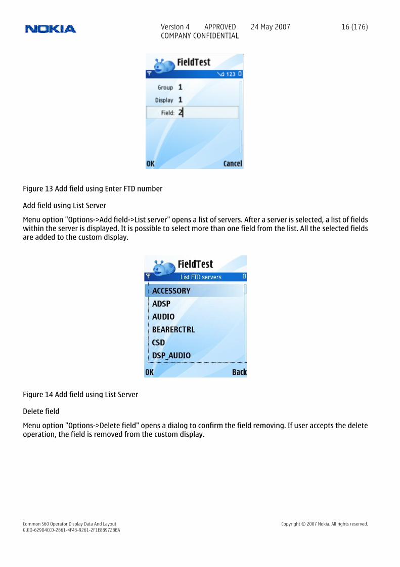
Figure 13 Add field using Enter FTD number
Add field using List Server
Menu option "Options->Add field->List server" opens a list of servers. After a server is selected, a list of fieldswithin the server is displayed. It is possible to select more than one field from the list. All the selected fieldsare added to the custom display.
Figure 14 Add field using List Server
Delete field
Menu option "Options->Delete field" opens a dialog to confirm the field removing. If user accepts the deleteoperation, the field is removed from the custom display.
Version 4 APPROVED 24 May 2007COMPANY CONFIDENTIAL
16 (176)
Common S60 Operator Display Data And Layout Copyright © 2007 Nokia. All rights reserved.GUID-629D4CCD-2861-4F43-9261-2F1E889728BA

Figure 15 Delete field from a custom display
Settings
The settings dialog found in Custom display edit view is used to edit the current custom display only.
Figure 16 Custom display edit view settings
Display name
Display name setting is used to define the name of the custom display. The name is visible on the navi paneof the custom display view.
Display mode
Display mode setting defines the layout of the custom display. Setting has three values:
• Names: Show only the field names on custom display
• Values: Show only the field values on custom display. Values are shown in two columns.
• Both: Show both field names and values on custom display. Names are shown on the left column, valueson the right column.
Trace
Version 4 APPROVED 24 May 2007COMPANY CONFIDENTIAL
17 (176)
Common S60 Operator Display Data And Layout Copyright © 2007 Nokia. All rights reserved.GUID-629D4CCD-2861-4F43-9261-2F1E889728BA

Trace setting determines if the subblocks on custom display should be written in trace file or not. If the traceis turned on, the file is defined in the following tracefile name setting. If the trace is turned off, then thetracefile name is ignored.
Tracefile name
Tracefile name is the file to use if trace is turned on. Trace file can be found from C:\data\fieldtest.
ALARMS VIEW
An alarm is a set of fields that has a name and condition when it alarms. In FieldTest application the alarmcondition can be defined in terms of number of changes in field values. When an alarm alarms, a notificationis displayed and optionally a tone is played
Alarms are used to notify user about changes in values of certain fields. User can add, modify and removealarms at runtime.
Alarms list view
This view shows all alarms on a list. The other alarm view, the edit view, is used to modify a single alarm.
View content
Below is an example of an alarm view.
Figure 17 Alarms list view
Navi pane contains the name of the active alarm.
Each alarm is presented on its own line on the list. The check symbol at the front of the line indicates thealarm is enabled. If the check symbol is not present, then the alarm is disabled and the field changes are notmonitored.
Alarm name is followed by two numbers separated by a slash character. The left side number is the currentnumber of field value changes. That is, how many times all the fields in alarm have changed in total. Theright side number is the condition, the number of changes required to start alarming.
Keyboard shortcuts
Alarms view has some keyboard shortcuts to perform actions on alarms.
Enable and disable alarm
The select key can be used to toggle alarm enabled and disabled.
Menu options
Version 4 APPROVED 24 May 2007COMPANY CONFIDENTIAL
18 (176)
Common S60 Operator Display Data And Layout Copyright © 2007 Nokia. All rights reserved.GUID-629D4CCD-2861-4F43-9261-2F1E889728BA

Alarms view has the general menu options: View, Info and Exit. There are also some view specific menuoptions.
Deactivate all alarms
Menu option "Options->Deactivate all alarms" allows user to turn all alarms off at once. Alarms can be laterturned on one by one.
Edit alarm
Menu option "Options->Edit alarm" opens the current alarm in the edit view. This allows user to modify alarmsettings and add and remove fields in the alarm.
Add alarm
Menu option "Options->Add alarm" creates a new empty alarm and opens the edit view for the new alarm.This allows the user to set the alarm settings and add fields to the alarm.
Delete alarm
Menu option "Options->Delete alarm" opens a dialog to confirm the alarm removing. if user accepts the deleteoperation, the alarm is removed.
Figure 18 Delete alarm
Alarms edit view
View content
This view contains a list of all fields included in an alarm. The view is used to modify alarm settings and toadd and remove fields from the alarm.
Version 4 APPROVED 24 May 2007COMPANY CONFIDENTIAL
19 (176)
Common S60 Operator Display Data And Layout Copyright © 2007 Nokia. All rights reserved.GUID-629D4CCD-2861-4F43-9261-2F1E889728BA

Figure 19 Edit alarm view
Menu options
Add field
Menu option "Options->Add field" has the three submenu options familiar from edit custom display view.The options are:
• List FTD display: Select common group, then display, then fields
• Enter FTD number: Enter the number of common group, display and field
• List server: Select server then fields
Delete field
Menu option "Options->Delete field" opens a dialog to confirm the field removing. If user accepts the deleteoperation, the field is removed from the alarm.
Figure 20 Delete field from alarm
Settings
The settings dialog found in Alarm edit view is used to edit settings of the current alarm only.
Version 4 APPROVED 24 May 2007COMPANY CONFIDENTIAL
20 (176)
Common S60 Operator Display Data And Layout Copyright © 2007 Nokia. All rights reserved.GUID-629D4CCD-2861-4F43-9261-2F1E889728BA

Figure 21 Alarm edit view settings
Alarm name
Alarm name setting is used to define the name for the alarm. The name is used when the alarm alarms. It isalso visible on the alarms list and on the edit alarm view.
Amount
Amount is the number of field value changes required to make the alarm alarming.
Alarm state
Alarm state defines if the alarm is enabled or disabled. A disabled alarm does not monitor field value changesand thus it never alarms.
Alarm tone
Alarm tone can be selected to hear the alarm.
Version 4 APPROVED 24 May 2007COMPANY CONFIDENTIAL
21 (176)
Common S60 Operator Display Data And Layout Copyright © 2007 Nokia. All rights reserved.GUID-629D4CCD-2861-4F43-9261-2F1E889728BA

2 Group 01: GSM Signaling displays which can be visible to network operators
2.1 Group 01 InformationThe network operators can activate these signaling displays. Before field test displays are visible, mobile hasto be modified. With the normal production mobile, field test displays are not working.
2.2 Display 01.01: Information of the serving cell
S60 Data display
aChannel num bbbRx level cccTx power lev dddGprs attach
eTS / TA ffRx / R time gC1 / C2
hhhh
Band/CHtyiii
Amr U/Amr D
jjjkk llll
mm
n o
Fields
Abbr Server Sub-block id Format Mode Description
a GSS FTD_SB_HOPPING S R,I,O H, if carrier numbers are scrolled when hopping is on.Otherwise empty
b(3) GSS FTD_SB_CARRIER S R,I,O When mobile is on TCH: DCH carrier number of servingcell in decimal.
When mobile is NOT on TCH: CH means carrier numberof serving cell in decimal.
If hopping is on, used channels are scrolled whendisplay is updated
ERR means that mobile is out of band.
c(3) GSS FTD_SB_RX_LEVEL B:D R,I,O Rx level in dBm, minus sign not shown if <-100
d(3) GSS FTD_SB_TX_LEVEL S R,I,O Tx power level. If transmitter is on, symbol * is shownin front of the power level value.
e GSS FTD_SB_TIME_SLOT B:D R,I,O Time Slot, range is 0 - 7
f(2) GSS FTD_SB_TIMING_ADV B:D R,I,O Timing advance, range is 0 - 63
g GSS FTD_SB_RX_QUALITY B:D R,I,O Rx quality (sub), range is 0 - 7
h(4) GSS FTD_SB_RADIO_LINK_TIMEOUT B:D R,I,O Radio Link Timeout value. If value is negative, 0 isshown. Maximum value is 64. When mobile is NOT onTCH then xx is show
i(3) GSS FTD_SB_C1 S R,I,O Value of the path loss criteria (C1). Range is -99 - 999.ERR means that the value is out of range, e.g. becauseit was not able to be calculated
j(3) GSS FTD_SB_C2 S R,I,O Value of the cell reselection criteria (C2). Range is -99- 999. If phone is phase 1 then C1 value is shown. ERRmeans that the value is out of range, e.g. because itwas not able to be calculated.
k(2) GSS FTD_SB_CURR_BAND B:D R,I,O Currently used band.Values:
9 = GSM900,
18 = GSM1800,
19 = GSM1900 .. extensible for future
Version 4 APPROVED 24 May 2007COMPANY CONFIDENTIAL
22 (176)
Common S60 Operator Display Data And Layout Copyright © 2007 Nokia. All rights reserved.GUID-629D4CCD-2861-4F43-9261-2F1E889728BA

Abbr Server Sub-block id Format Mode Description
l(4) GSS FTD_SB_TYPE_OF_CURR_CH S R,I,O Type of current channel
THR0: TCH HR subchannel 0
THR1: TCH HR subchannel 1
AHS0: TCH AHS subchannel 0
AHS1: TCH AHS subchannel 1
TFR: TCH FR
AFS: TCH AFS
TEFR: TCH EFR
F144: TCH FR data channel, speed 14.4 kbps
F96: TCH FR data channel, speed 9.6 kbps
F72: TCH FR data channel, speed 7.2 kbps
F48 : TCH FR data channel, speed 4.8 kbps
F24 : TCH FR data channel, speed 2.4 kbps
H480 : TCH HR data channel, speed 4.8 kbps, subch 0
H481 : TCH HR data channel, speed 4.8 kbps, subch 1
H240 : TCH HR data channel, speed 2.4 kbps, subch 0
H241 : TCH HR data channel, speed 2.4 kbps, subch 1
FA: TCH FR signaling only (FACCH) channel
FAH0 : TCH HR signaling only (FACCH) channel, subch0
FAH1 : TCH HR signaling only (FACCH) channel, subch1
PCCC, PBCC, PAGC : GPRS packet control channel
PNDR: GPRS non-DRX mode (in PCCCH)
PDTC: GPRS traffic channel
NDRX: GPRS
non-DRX mode (in CCCH)
SDCC : SDCCH
AGCH : AGCH
CCCH : CCCH
CBCH : CCCH and cell broadcast receiving on
BCCH : BCCH
SEAR : SEARCH
NSPS : MS is in No Serv Power Save state
m(2) GPDS FTD_SB_GPDS_ATT_AND_PDP S R,I,O G if MS is GSM-GPRS attached, GP if attached and PDPcontext created, U if UMTS-GPRS attached, UP ifattached and PDP context created, otherwise empty.
n GSM_DSP FTD_SB_AMR_UL_MODE B:D R,I,O Current absolute uplink mode on AMR channels, (0-7).0=4.75, 1=5.15, 2=5.9, 3=6.7, 4=7.4, 5=7.95, 6=10.2,7=12.2.
o GSM_DSP FTD_SB_AMR_DL_MODE B:D R,I,O Current absolute downlink mode on AMR channels.See definition above.
2.3 Display 01.02: More information of the serving cell
Version 4 APPROVED 24 May 2007COMPANY CONFIDENTIAL
23 (176)
Common S60 Operator Display Data And Layout Copyright © 2007 Nokia. All rights reserved.GUID-629D4CCD-2861-4F43-9261-2F1E889728BA

S60 Data display
aaPaging modebmax RACH retrcRoaming indddBSIC valueeeCC CausefRx qualitygggCRO / Hopping hh
PenT / HCh iiiMAIO / HSN
jkk ll
Fields
Abbr Server Sub-block id Format Mode Description
a(2) GSS FTD_SB_PAGING_MODE S R,I,O Paging mode
NO : normal paging
EX : extended paging
RO : paging reorganization
SB : same as before
b GSS FTD_SB_MAX_RAND_ACC_TRA B:D R,I,O Maximum number of Random Access retransmission
c GSS FTD_SB_ROAMING_IND S R,I,O Roaming indicator, values are R or empty.
d(2) GSS FTD_SB_BSIC B:D R,I,O Letter B and BSIC value, range is 0 - 63.
e(2) GSS FTD_SB_LAST_CALL_REL_REAS B:D R,I,O Reason of last call release. Cause from messagesdisconnect and release complete.
f GSS FTD_SB_RX_QUALITY B:D R,I,O Rx quality (sub), range is 0 - 7
g(3) GSS FTD_SB_CELL_RESEL_OFFSET B:D R,I,O Cell reselect offset, range 0 - 126 dB. 0 - 63 * 2 dB. 'xxx'in active mode.
h(2) GSS FTD_SB_TEMP_OFFSET B:D R,I,O Temporary offset, range 0 - 60 dB. 0 - 7 * 10 dB. 70 dBmeans infinite time. 'xx' in active mode.
i(3) GSS FTD_SB_PENALTY_TIME W:D R,I,O Penalty time, range 0 - 620 s. 0 - 31 * 20 s. 'xxx' inactive mode
j GSS FTD_SB_HOPP_CH B:D R,I,O Hopping channel
0 Single RF channel
1 RF hopping channel
k(2) GSS FTD_SB_MOB_ALLOC_INDEX B:D R,I,O Mobile allocation index offset, MAIO Range: 00 to 63 /xx when H=0
l(2) GSS FTD_SB_HSN B:D R,I,O Hopping sequence number, HSN Range: 00 to 63 / xxwhen H=0
2.4 Display 01.03: Information of the serving cell, 1st and 2nd neighbor1. row: serving cell information
2. row: 1. neighbor information
3. row: 2. neighbor information
4. row, mn: 1. neighbor information
4. row, op: 2. neighbor information
Version 4 APPROVED 24 May 2007COMPANY CONFIDENTIAL
24 (176)
Common S60 Operator Display Data And Layout Copyright © 2007 Nokia. All rights reserved.GUID-629D4CCD-2861-4F43-9261-2F1E889728BA

S60 Data display
aaa
Serving cell info
bbbCH:
cccC1:
dddRX:
eee
C2:
fff1. Neighbor info
ggg2. Neighbor info
hhh
1. Neighbor ariii
2. Neighbor ar
jjj kkk lllmnop
Fields
Abbr Server Sub-block id Format Mode Description
a(3) GSS FTD_SB_CARRIER S R,I,O When mobile is on TCH: DCH carrier number of servingcell in decimal.
When mobile is NOT on TCH: CH means carrier numberof serving cell in decimal.
If hopping is on, used channels are scrolled whendisplay is updated
ERR means that mobile is out of band.
b(3) GSS FTD_SB_C1S S R,I,O C1 value of serving cell, range is -99 - 999, displayedonly in idle mode. ERR means that the value is out ofrange, e.g. because it was not able to be calculated.Instead of C1 value, letter 'B' and BSIC value will bedisplayed in active mode.
c(3) GSS FTD_SB_RX_LEVEL B:D R,I,O Rx level in dBm, minus sign not shown if <-100
d(3) GSS FTD_SB_C2S S R,I,O C2 value of serving cell, range is -99 - 999. ERR meansthat the value is out of range, e.g. because it was notable to be calculated.
e(3) GSS FTD_SB_CARRIER_1_NEIGH S R,I,O Carrier number of 1. neighbor in decimal
f(3) GSS FTD_SB_C1_1_NEIGH S R,I,O C1 of 1. neighbor value, range is -99 - 999, displayedonly in idle mode. ERR means that the value is out ofrange, e.g. because it was not able to be calculated.Instead of C1 value, letter 'B' and BSIC value will bedisplayed in active mode.
g(3) GSS FTD_SB_RX_LEVEL_1_NEIGH B:D R,I,O Rx level of 1. neighbor in dBm, minus sign not shownif <=-100
h(3) GSS FTD_SB_C2_1_NEIGH S R,I,O C2 of 1. neighbor value, range is -99 - 999. ERR meansthat the value is out of range, e.g. because it was notable to be calculated.
i(3) GSS FTD_SB_CARRIER_2_NEIGH S R,I,O Carrier number of 2. neighbor in decimal
j(3) GSS FTD_SB_C1_2_NEIGH S R,I,O C1 value of 2. neighbor, range is -99 - 999, displayedonly in idle mode. ERR means that the value is out ofrange, e.g. because it was not able to be calculated.Instead of C1 value, letter 'B' and BSIC value will bedisplayed in active mode.
k(3) GSS FTD_SB_RX_LEVEL_2_NEIGH B:D R,I,O Rx level of 2. neighbor in dBm, minus sign not shownif <=-100
l(3) GSS FTD_SB_C2_2_NEIGH S R,I,O C2 value of 2. neighbor, range is -99 - 999. ERR meansthat the value is out of range, e.g. because it was notable to be calculated.
m GSS FTD_SB_LOCATION_AREA_INFO_1 S R,I,O F is shown if cell is in a forbidden location area,otherwise location is empty.
n GSS FTD_SB_CELL_PRIORITY_1 S R,I,O B is Barred, N is normal priority and L is low priority,otherwise location is empty.
Version 4 APPROVED 24 May 2007COMPANY CONFIDENTIAL
25 (176)
Common S60 Operator Display Data And Layout Copyright © 2007 Nokia. All rights reserved.GUID-629D4CCD-2861-4F43-9261-2F1E889728BA

Abbr Server Sub-block id Format Mode Description
o GSS FTD_SB_LOCATION_AREA_INFO_2 S R,I,O F is shown if cell is in a forbidden location area,otherwise location is empty.
p GSS FTD_SB_CELL_PRIORITY_2 S R,I,O B is Barred, N is normal priority and L is low priority,otherwise location is empty.
2.5 Display 01.04: Information of the 3rd, 4th and 5th neighbor1. row: 3. neighbor information
2. row: 4. neighbor information
3. row: 5. neighbor information
4. row, mn: 3. neighbor information
5. row, op: 4. neighbor information
6. row, qr: 5. neighbor information
S60 Data display
aaa3. Neighbor info
bbb4. Neighbor info
ccc
5. Neighbor info
ddd
3. Neighbor ar
eee
4. Neighbor ar
fff
5. Neighbor ar
ggg hhh
iii jjj kkk lllmnopqr
Fields
Abbr Server Sub-block id Format Mode Description
a(3) GSS FTD_SB_CARRIER_3_NEIGH S R,I,O Carrier number of 3. neighbor in decimal
b(3) GSS FTD_SB_C1_3_NEIGH S R,I,O C1 value of 3. neighbor, range is -99 - 999, displayedonly in idle mode. ERR means that the value is out ofrange, e.g. because it was not able to be calculated.Instead of C1 value, letter 'B' and BSIC value will bedisplayed in active mode.
c(3) GSS FTD_SB_RX_LEVEL_3_NEIGH B:D R,I,O Rx level of 3. neighbor in dBm, minus sign not shownif <=-100
d(3) GSS FTD_SB_C2_3_NEIGH S R,I,O C2 value of 3. neighbor, range is -99 - 999. ERR meansthat the value is out of range, e.g. because it was notable to be calculated.
e(3) GSS FTD_SB_CARRIER_4_NEIGH S R,I,O Carrier number of 4. neighbor in decimal
f(3) GSS FTD_SB_C1_4_NEIGH S R,I,O C1 value of 4. neighbor, range is -99 - 999, displayedonly in idle mode. ERR means that the value is out ofrange, e.g. because it was not able to be calculated.Instead of C1 value, letter 'B' and BSIC value will bedisplayed in active mode.
g(3) GSS FTD_SB_RX_LEVEL_4_NEIGH B:D R,I,O Rx level of 4. neighbor in dBm, minus sign not shownif <=-100
h(3) GSS FTD_SB_C2_4_NEIGH S R,I,O C2 value of 4. neighbor, range is -99 - 999. ERR meansthat the value is out of range, e.g. because it was notable to be calculated.
i(3) GSS FTD_SB_CARRIER_5_NEIGH S R,I,O Carrier number of 5. neighbor in decimal
Version 4 APPROVED 24 May 2007COMPANY CONFIDENTIAL
26 (176)
Common S60 Operator Display Data And Layout Copyright © 2007 Nokia. All rights reserved.GUID-629D4CCD-2861-4F43-9261-2F1E889728BA

Abbr Server Sub-block id Format Mode Description
j(3) GSS FTD_SB_C1_5_NEIGH S R,I,O C1 value of 5. neighbor, range is -99 - 999, displayedonly in idle mode. ERR means that the value is out ofrange, e.g. because it was not able to be calculated.Instead of C1 value, letter 'B' and BSIC value will bedisplayed in active mode.
k(3) GSS FTD_SB_RX_LEVEL_5_NEIGH B:D R,I,O Rx level of 5. neighbor in dBm, minus sign not shownif <=-100
l(3) GSS FTD_SB_C2_5_NEIGH S R,I,O C2 value of 5. neighbor, range is -99 - 999. ERR meansthat the value is out of range, e.g. because it was notable to be calculated.
m GSS FTD_SB_LOCATION_AREA_INFO_3 S R,I,O F is shown if cell is in a forbidden location area,otherwise location is empty.
n GSS FTD_SB_CELL_PRIORITY_3 S R,I,O B is Barred, N is normal priority and L is low priority,otherwise location is empty.
o GSS FTD_SB_LOCATION_AREA_INFO_4 S R,I,O F is shown if cell is in a forbidden location area,otherwise location is empty.
p GSS FTD_SB_CELL_PRIORITY_4 S R,I,O B is Barred, N is normal priority and L is low priority,otherwise location is empty.
q GSS FTD_SB_LOCATION_AREA_INFO_5 S R,I,O F is shown if cell is in a forbidden location area,otherwise location is empty.
r GSS FTD_SB_CELL_PRIORITY_5 S R,I,O B is Barred, N is normal priority and L is low priority,otherwise location is empty.
2.6 Display 01.05: Information of the 6th, 7th and 8th neighbor1. row: 6. neighbor information
2. row: 7. neighbor information
3. row: 8. neighbor information
4. row, ef: 6. neighbor information
5. row, gh: 7. neighbor information
6. row, ij: 8. neighbor information
S60 Data display
aaa6. Neighbor info
bbb7. Neighbor info
ccc
8. Neighbor info
ddd
6. Neighbor ar
eee
7. Neighbor ar
fff
8. Neighbor ar
ggg hhh
iii jjj kkk lllmnopqr
Fields
Abbr Server Sub-block id Format Mode Description
a(3) GSS FTD_SB_CARRIER_6_NEIGH S R,I,O Carrier number of 6. neighbor in decimal
b(3) GSS FTD_SB_C1_6_NEIGH S R,I,O C1 value of 6. neighbor, range is -99 - 999, displayedonly in idle mode. ERR means that the value is out ofrange, e.g. because it was not able to be calculated.Instead of C1 value, letter 'B' and BSIC value will bedisplayed in active mode.
Version 4 APPROVED 24 May 2007COMPANY CONFIDENTIAL
27 (176)
Common S60 Operator Display Data And Layout Copyright © 2007 Nokia. All rights reserved.GUID-629D4CCD-2861-4F43-9261-2F1E889728BA

Abbr Server Sub-block id Format Mode Description
c(3) GSS FTD_SB_RX_LEVEL_6_NEIGH B:D R,I,O Rx level of 6. neighbor in dBm, minus sign not shownif <=-100
d(3) GSS FTD_SB_C2_6_NEIGH S R,I,O C2 value of 6. neighbor, range is -99 - 999. ERR meansthat the value is out of range, e.g. because it was notable to be calculated.
e(3) GSS FTD_SB_CARRIER_7_NEIGH S R,I,O Carrier number of 7. neighbor in decimal
f(3) GSS FTD_SB_C1_7_NEIGH S R,I,O C1 value of 7. neighbor, range is -99 - 999, displayedonly in idle mode. ERR means that the value is out ofrange, e.g. because it was not able to be calculated.Instead of C1 value, letter 'B' and BSIC value will bedisplayed in active mode.
g(3) GSS FTD_SB_RX_LEVEL_7_NEIGH B:D R,I,O Rx level of 7. neighbor in dBm, minus sign not shownif <=-100
h(3) GSS FTD_SB_C2_7_NEIGH S R,I,O C2 value of 7. neighbor, range is -99 - 999. ERR meansthat the value is out of range, e.g. because it was notable to be calculated.
i(3) GSS FTD_SB_CARRIER_8_NEIGH S R,I,O Carrier number of 8. neighbor in decimal
j(3) GSS FTD_SB_C1_8_NEIGH S R,I,O C1 value of 8. neighbor, range is -99 - 999, displayedonly in idle mode. ERR means that the value is out ofrange, e.g. because it was not able to be calculated.Instead of C1 value, letter 'B' and BSIC value will bedisplayed in active mode.
k(3) GSS FTD_SB_RX_LEVEL_8_NEIGH B:D R,I,O Rx level of 8. neighbor in dBm, minus sign not shownif <=-100
l(3) GSS FTD_SB_C2_8_NEIGH S R,I,O C2 value of 8. neighbor, range is -99 - 999. ERR meansthat the value is out of range, e.g. because it was notable to be calculated.
m GSS FTD_SB_LOCATION_AREA_INFO_6 S R,I,O F is shown if cell is in a forbidden location area,otherwise location is empty.
n GSS FTD_SB_CELL_PRIORITY_6 S R,I,O B is Barred, N is normal priority and L is low priority,otherwise location is empty.
o GSS FTD_SB_LOCATION_AREA_INFO_7 S R,I,O F is shown if cell is in a forbidden location area,otherwise location is empty.
p GSS FTD_SB_CELL_PRIORITY_7 S R,I,O B is Barred, N is normal priority and L is low priority,otherwise location is empty.
q GSS FTD_SB_LOCATION_AREA_INFO_8 S R,I,O F is shown if cell is in a forbidden location area,otherwise location is empty.
r GSS FTD_SB_CELL_PRIORITY_8 S R,I,O B is Barred, N is normal priority and L is low priority,otherwise location is empty.
2.7 Display 01.06: Network selection displayThis display shows the last registered network country code and network code as well as the codes for fourforbidden networks and the first 3 preferred networks. If data isn't available there is shown xxx on the display.
1. row: last registered network - 1st forbidden network
2. row: 1st preferred network - 2nd forbidden network
3. row: 2nd preferred network - 3rd forbidden network
4. row: 3rd preferred network - 4th forbidden network
Version 4 APPROVED 24 May 2007COMPANY CONFIDENTIAL
28 (176)
Common S60 Operator Display Data And Layout Copyright © 2007 Nokia. All rights reserved.GUID-629D4CCD-2861-4F43-9261-2F1E889728BA

S60 Data display
aaaaaaLast Reg 1st forbidd
bbbbbb1st pref 2nd forbidd
cccccc2nd pref 3rd forbidd
dddddd3rd pref 4th forbidd
eeeeee
ffffff
gggggg
hhhhhh
Fields
Abbr Server Sub-block id Format Mode Description
a(6) GSS FTD_SB_LAST_REG DW:H R,I,O Last registred network
b(6) NETWORK
FTD_SB_FIRST_PREF S R,I,O 1. preferred network
c(6) NETWORK
FTD_SB_SECOND_PREF S R,I,O 2. preferred network
d(6) NETWORK
FTD_SB_THIRD_PREF S R,I,O 3. preferred network
e(6) GSS FTD_SB_1ST_FORBIDDEN_NW DW:H R,I,O 1. forbidden PLMN in SIM
f(6) GSS FTD_SB_2ND_FORBIDDEN_NW DW:H R,I,O 2. forbidden PLMN in SIM
g(6) GSS FTD_SB_3RD_FORBIDDEN_NW DW:H R,I,O 3. forbidden PLMN in SIM
h(6) GSS FTD_SB_4TH_FORBIDDEN_NW DW:H R,I,O 4. forbidden PLMN in SIM
2.8 Display 01.07: System information bits for serving cellThe following is picked from Phase2+ ETSI GSM 05.08 version 5.4.0, Section 8.4.3 ""Additional cell reportingrequirements for multiband MS"".
For a multi band MS the number of cells, for each frequency band supported, which shall be included in themeasurement report is indicated by the parameter, MULTIBAND_REPORTING. The meaning of different valuesof the parameter is specified as follows:
S60 Data display
a
Serving Cell System Info Bits
bE A H C I BR
cEC 2Ter MB G
d e f g
h i j k
Fields
Abbr Server Sub-block id Format Mode Description
a GSS FTD_SB_SYSTEM_INFO_BITS1 B:D R,I,O 1 is shown if emergency calls are supported, else 0
b GSS FTD_SB_SYSTEM_INFO_BITS2 B:D R,I,O 1 is shown if attach-detach-procedure is allowed, else0
Version 4 APPROVED 24 May 2007COMPANY CONFIDENTIAL
29 (176)
Common S60 Operator Display Data And Layout Copyright © 2007 Nokia. All rights reserved.GUID-629D4CCD-2861-4F43-9261-2F1E889728BA

Abbr Server Sub-block id Format Mode Description
c GSS FTD_SB_SYSTEM_INFO_BITS3 B:D R,I,O 1 is shown if half rate channels are supported, else 0
d GSS FTD_SB_SYSTEM_INFO_BITS4 B:D R,I,O 1 is shown if C2 values are broadcast, else 0
e GSS FTD_SB_SYSTEM_INFO_BITS5 B:D R,I,O 1 is shown if system information 7 and 8 arebroadcast, else 0
f GSS FTD_SB_SYSTEM_INFO_BITS6 B:D R,I,O 1 is shown if cell broadcast is supported, else 0
g GSS FTD_SB_SYSTEM_INFO_BITS7 B:D R,I,O 1 is shown if re-establishment is supported, else 0
h GSS FTD_SB_SYSTEM_INFO_BITS8 B:D R,I,O In idle mode 1 is shown if Early Classmark (ECSC)sending is supported, else 0. In dedicated mode(conversation) X is shown.
i GSS FTD_SB_SYSTEM_INFO_BITS9 B:D R,I,O In idle mode 1 is shown if 2-Ter messages aresupported, else 0. In dedicated mode (conversation)X is shown.
j GSS FTD_SB_SYSTEM_INFO_BITS10 B:D R,I,O MultiBand reporting decimal value (0,1,2,3) is shownif supported. This is shown both in idle and dedicatedmode.
k GSS FTD_SB_GPRS_SUPPORT B:D R,I,O 1 is shown if GPRS is supported, else 0
2.9 Display 01.08: Paging repeat period, TMSI, periodic location update, AFC and AGC
S60 Data display
aaaaaaaaTMSI valuebbbCurr T3212cccInitial T3212dPaging repeateeDownlink failffTCH/SDCCH GagggggVCTCXO AFChhhChannel num
Fields
Abbr Server Sub-block id Format Mode Description
a(8) GSS FTD_SB_TMSI DW:H R,I,O TMSI value in hex format
b(3) GSS FTD_SB_T3212 B:D R,I,O Current value of T3212 counter (range is 000 - 'ccc',where 1 means 6 min time. So, if this value is 2 lessthan 'ccc' then next periodic location updating will bemade within 2 * 6 min = 12 minutes
c(3) GSS FTD_SB_T3212_TIMEOUT B:D R,I,O Timeout value of T3212 counter (range is 000 - 240,where 1 means 6 min time between location updatesand 240 means 240 * 6 min = 24 h between locationupdates. 000 means that periodic location update isnot in use.) This value is received from the network.
d GSS FTD_SB_PRP B:D R,I,O Value of paging repeat period (range is 2 - 9, whenpaging is in every second multiframe, mobile takesmore current than if it were in every 9th multiframe)
e(2) GSS FTD_SB_DOWNLINK_SIGN_FAIL B:D R,I,O Downlink signaling failure value. If value is negative,0 is shown. Maximum value is 45. When mobile is onTCH then xx is shown
f(2) GSS FTD_SB_GAIN_ON_TCH B:D R,I,O Gain value on TCH/SDCCH, range is 0 - 93
g(5) GSS FTD_SB_VCTCXO_AFC_DAC W:D R,I,O VCTCXO AFC DAC control, range is -1024 - 1023
h(3) GSS FTD_SB_CARRIER S R,I,O When mobile is on TCH: DCH carrier number of servingcell in decimal.
Version 4 APPROVED 24 May 2007COMPANY CONFIDENTIAL
30 (176)
Common S60 Operator Display Data And Layout Copyright © 2007 Nokia. All rights reserved.GUID-629D4CCD-2861-4F43-9261-2F1E889728BA

Abbr Server Sub-block id Format Mode DescriptionWhen mobile is NOT on TCH: CH means carrier numberof serving cell in decimal.
If hopping is on, used channels are scrolled whendisplay is updated
ERR means that mobile is out of band.
2.10 Display 01.09: Network parametersLAC and CID may be in hex format in some projects. Or even both decimal and hexadecimal formats may beshown on the same line.
S60 Data display
aaa
Channel numCellIdentifier
Network parameters
bbbCountry code
cccccNetwork code
ddd
Location area
eeeeeeeeee
Serving cell
Fields
Abbr Server Sub-block id Format Mode Description
a(3) GSS FTD_SB_REG_CC S R,I,O MCC value in decimal (MCC=Mobile Country Code)
b(3) GSS FTD_SB_REG_MNC S R,I,O MNC value in decimal (MNC=Mobile Network Code).Three digits are shown only in DCS1900. In othersystems only two digits are shown.
c(5) GSS FTD_SB_LAC W:D R,I,O LAC value in decimal (LAC=Location Area Code)
d(3) GSS FTD_SB_CARRIER S R,I,O When mobile is on TCH: DCH carrier number of servingcell in decimal.
When mobile is NOT on TCH: CH means carrier numberof serving cell in decimal.
If hopping is on, used channels are scrolled whendisplay is updated
ERR means that mobile is out of band.
e(10) GSS FTD_SB_CELL_ID DW:D R,I,O Cell Identifier in decimal format. Data format is DW:Dfrom GSS ISI header version 2.1 onwards. Older GSS ISIheaders handle this as W:D
2.11 Display 01.10: Ciphering, hopping DTX status and IMSIThese values are updated only on the TCH.
Version 4 APPROVED 24 May 2007COMPANY CONFIDENTIAL
31 (176)
Common S60 Operator Display Data And Layout Copyright © 2007 Nokia. All rights reserved.GUID-629D4CCD-2861-4F43-9261-2F1E889728BA

S60 Data display
aaa
IMSI attach
Updated only on TCH
bbb
Ciphering val
ccc
Hopping val
ddd
DTX value
Fields
Abbr Server Sub-block id Format Mode Description
a(3) GSS FTD_SB_CIPH S R,I,O Ciphering value, OFF/A51/A52
b(3) GSS FTD_SB_HOPP_STATUS S R,I,O Hopping value, ON/OFF
c(3) GSS FTD_SB_DTX_VALUE S R,I,O DTX value ON/OFF
d(3) GSS FTD_SB_IMSI_ATT S R,I,O IMSI attach ON : IMSI attach on OFF : IMSI attach off
2.12 Display 01.11: Uplink DTX switching displayWith this display it is possible to change MS to use DTX or not, if BS allows MS to decide it. This display mustbe activated from MENU to change DTX state. When MENU is not active and the user is scrolling field testdisplays with NEXT and PREVIOUS, the DTX state will not change.
S60 Data display
aaaaaaaaaa
to use DTX or not. Useoptions to change
DTX modeDefault DTXDTX from BS
Execute display
bbb
With this display it is
ccc
possible to change MS
Fields
Abbr Server Sub-block id Format Mode Description
a(10) GSS FTD_SB_DTX_STATUS S R,I,O Status of switched mode.
DTX:ON : MS uses DTX
DTX:OFF : MS does not use DTX
DTX:DEF : MS use default state of DTX. Defined inMS_PAR.H
NOTALLOWED: BS does not allow MS to decide if ituses DTX or not.
b(3) GSS FTD_SB_DTX_DEF S R,I,O Default state of DTX. Defined in MS_PAR.H. The valueis either ON or OFF
c(3) GSS FTD_SB_DTX_FROM_BS S R,I,O Is DTX value from BS
MAY : BS allows MS to decide if it uses dtx or not onuplink.
USE : BS controls MS to use dtx (on uplink)
Version 4 APPROVED 24 May 2007COMPANY CONFIDENTIAL
32 (176)
Common S60 Operator Display Data And Layout Copyright © 2007 Nokia. All rights reserved.GUID-629D4CCD-2861-4F43-9261-2F1E889728BA

Abbr Server Sub-block id Format Mode DescriptionNOT : BS controls MS not to use dtx (on uplink)
EXE GSS FTD_SB_DTX_STATUS_CHANGE B:D R,I,O Toggle DTX status.
2.13 Display 01.12: Storing and removing BTS_TEST carrierThis display is used to change BTS_TEST carrier on permanent memory. If BTS_TEST carrier is stored onpermanent memory each time the mobile sends a search list it uses only the carrier number stored on MobileStation permanent memory. Also the neighbor information from system information messages is ignored.If the BTS_TEST carrier is not stored, then the mobile behaves normally (i.e. does the neighbor measurementsaccording the GSM specifications).
Mobile is searching only one frequency. Neighbor measurements are not done.
Mobile is behaving normally. Neighbor measurements are done.
To store BTS test carrier, perform following steps:
1. Press the Menu button.
2. Scroll in the main menu loop to field test display item.
3. Press the Select button.
4. Select this display in input mode by entering 0112 (TEST GROUP;TEST DISPLAY) to the query prompt.
5. Test input promt will be shown on the display, enter the channel number in display.
6. Confirm with the Ok button.
7. Switch power off and on.
8. If activation succeeded, there is text "BTS TEST LOCKED, CH:" in display 12 of group 1.
To deactivate BTS tests, perform following steps:
1. Press the Menu button.
2. Scroll in the main menu loop to field test display item.
3. Press the Select button.
4. Select this display in input mode by entering 0112 (TEST GROUP;TEST DISPLAY) to the query prompt.
5. Test input promt will be shown on the display, enter the 3333 as a channel number in display
6. Confirm with the Ok button.
7. Switch power off and on.
8. If deactivation succeeded, there is text "BTS TEST OFF" in display 12 of group 1.
The legal carrier numbers:
Band Carrier Numbers
GSM450 259-293
GSM480 306-340
GSM850 128-251
GSM900 1-124
GSM1800 512-885
GSM1900 512-810
E-GSM 0, 975-1023
R-GSM 955-974
Version 4 APPROVED 24 May 2007COMPANY CONFIDENTIAL
33 (176)
Common S60 Operator Display Data And Layout Copyright © 2007 Nokia. All rights reserved.GUID-629D4CCD-2861-4F43-9261-2F1E889728BA

S60 Data display
aaaa
With this display it ispossible to changeBTS_TEST carrier. Useoptions to change
BTS TEST
Execute display
Fields
Abbr Server Sub-block id Format Mode Description
a(4) NETWORK
FTD_SB_BTS_STATUS S R,I,O BTS test status
INPUT(4) NETWORK
FTD_SB_BTS_TEST DW:D R,I,O BTS test
2.14 Display 01.13: Toggle Cell Barred StatusThis test is meant to be used when some cells are tested prior taking them into commercial use. By settingthe barring on in the base station normal GSM phones will not try to register these barred cells. By selectingcell barring reversed, the MS will only use the cells to be tested. However, if at the same time it is wantedthat MS will be capable to use normal network cell barring ignored can be set. This display will show the cellbarring mode.
NOTE! If a cell has been selected before barring state is changed the selected cell may have different barringstate than what the display shows. After reselection the cell barring state is working for sure.
To change Cell Barring status, perform following steps:
1. Press the Menu button.
2. Scroll in the main menu loop to field test display item.
3. Press the Select button.
4. Select this display in executive mode by entering 0113 (TEST GROUP;TEST DISPLAY) to the query prompt.
5. Confirm with the Ok button.
6. If activation succeeded, there is text "CELL BARR" in display 13 of group 1.
S60 Data display
aaaaaaaa
With this display it ispossible to changeCall bearer status. Useoptions to change
CALL BEARER
Execute display
Version 4 APPROVED 24 May 2007COMPANY CONFIDENTIAL
34 (176)
Common S60 Operator Display Data And Layout Copyright © 2007 Nokia. All rights reserved.GUID-629D4CCD-2861-4F43-9261-2F1E889728BA

Fields
Abbr Server Sub-block id Format Mode Description
a(8) GSS FTD_SB_CELL_BARR_IND_STATUS S R,I,O Cell Barring status
EXE GSS FTD_ SB_CELL_BARR_IND_STATUS_CHANGE
B:D R,I,O Toggle Cell Barring status
2.15 Display 01.14: Modify last used bandThis display is applicable only in phones having both European and American frequencies.
With this display it is possible to manipulate the "last used band". In multi-band products this paramater isused at startup to decide which band shall be searched first. In most cases the last used band is the mostpromising band to find networks in. Nevertheless, for testing purposes it is helpful to have influence on thisdecision.
If at startup no "last used band" is found in the memory, the "Default" setting (Europe or America) will beeffective.
1. Press the Menu button.
2. Scroll in the main menu loop to field test display item.
3. Press the Select button.
4. Select this display in input mode by entering 01.14 (TEST GROUP;TEST DISPLAY) to the query prompt.
5. Test input prompt will activate, enter the desired band code (see the table below) in display.
6. Confirm with the Ok button.
7. REMOVE BATTERY or POWER SUPPLY
NOTE: In normal operation the last used band is saved to the memory at power-down. If this value is writtenvia Test Display 01.14, the phone MUST NOT be powerd off normally afterwards, because then the user-setvalue will be overwritten. The power supply has be interrupted instead.
Band codes:
Band Code Meaning
9 GSM900
18 GSM1800
19 GSM1900
Other Delete stored value
S60 Data display
aa
With this display it ispossible to set bandwhich will be searchedfirst after startup
Use options to set.
Execute display
Version 4 APPROVED 24 May 2007COMPANY CONFIDENTIAL
35 (176)
Common S60 Operator Display Data And Layout Copyright © 2007 Nokia. All rights reserved.GUID-629D4CCD-2861-4F43-9261-2F1E889728BA

Fields
Abbr Server Sub-block id Format Mode Description
a(2) GSS FTD_SB_LAST_USED_BAND_READ B:D R,I,O Last used band, see the table below
INPUT(4) GSS FTD_SB_LAST_USED_BAND_SET DW:D R,I,O Write value to memory
2.16 Display 01.15: Equivalent PLMN displayThis display shows the equivalent PLMN list. If data isn't available xxx is shown on the display.
1. row: 1st equivalent PLMN - 5th equivalent PLMN
2. row: 2nd equivalent PLMN - 6th equivalent PLMN
3. row: 3rd equivalent PLMN - 7th equivalent PLMN
4. row: 4th equivalent PLMN - 8th equivalent PLMN
S60 Data display
aaaaaa
8_PLMN
Equivalent PLMNs
bbbbbb1_PLMN
cccccc2_PLMN
dddddd3_PLMN
eeeeee4_PLMN
ffffff5_PLMN
gggggg6_PLMN
hhhhhh7_PLMN
Fields
Abbr Server Sub-block id Format Mode Description
a(6) GSS FTD_SB_1_EQUIV_PLMN DW:H R,I,O Equivalent PLMN
b(6) GSS FTD_SB_2_EQUIV_PLMN DW:H R,I,O Equivalent PLMN
c(6) GSS FTD_SB_3_EQUIV_PLMN DW:H R,I,O Equivalent PLMN
d(6) GSS FTD_SB_4_EQUIV_PLMN DW:H R,I,O Equivalent PLMN
e(6) GSS FTD_SB_5_EQUIV_PLMN DW:H R,I,O Equivalent PLMN
f(6) GSS FTD_SB_6_EQUIV_PLMN DW:H R,I,O Equivalent PLMN
g(6) GSS FTD_SB_7_EQUIV_PLMN DW:H R,I,O Equivalent PLMN
h(6) GSS FTD_SB_8_EQUIV_PLMN DW:H R,I,O Equivalent PLMN
2.17 Display 01.16: Equivalent PLMN displayThis display shows the equivalent PLMN list. If data isn't available xxx is shown on the display.
1. row: 9th equivalent PLMN - 13th equivalent PLMN
2. row: 10th equivalent PLMN - 14th equivalent PLMN
3. row: 11th equivalent PLMN - 15th equivalent PLMN
4. row: 12th equivalent PLMN - 16th equivalent PLMN
Version 4 APPROVED 24 May 2007COMPANY CONFIDENTIAL
36 (176)
Common S60 Operator Display Data And Layout Copyright © 2007 Nokia. All rights reserved.GUID-629D4CCD-2861-4F43-9261-2F1E889728BA

S60 Data display
aaaaaa
16_PLMN
Equivalent PLMNs
bbbbbb9_PLMN
cccccc10_PLMN
dddddd11_PLMN
eeeeee12_PLMN
ffffff13_PLMN
gggggg14_PLMN
hhhhhh15_PLMN
Fields
Abbr Server Sub-block id Format Mode Description
a(6) GSS FTD_SB_9_EQUIV_PLMN DW:H R,I,O Equivalent PLMN
b(6) GSS FTD_SB_10_EQUIV_PLMN DW:H R,I,O Equivalent PLMN
c(6) GSS FTD_SB_11_EQUIV_PLMN DW:H R,I,O Equivalent PLMN
d(6) GSS FTD_SB_12_EQUIV_PLMN DW:H R,I,O Equivalent PLMN
e(6) GSS FTD_SB_13_EQUIV_PLMN DW:H R,I,O Equivalent PLMN
f(6) GSS FTD_SB_14_EQUIV_PLMN DW:H R,I,O Equivalent PLMN
g(6) GSS FTD_SB_15_EQUIV_PLMN DW:H R,I,O Equivalent PLMN
h(6) GSS FTD_SB_16_EQUIV_PLMN DW:H R,I,O Equivalent PLMN
Version 4 APPROVED 24 May 2007COMPANY CONFIDENTIAL
37 (176)
Common S60 Operator Display Data And Layout Copyright © 2007 Nokia. All rights reserved.GUID-629D4CCD-2861-4F43-9261-2F1E889728BA

3 Group 04: GSM Test Timers SMS and Call Counter Displays
3.1 Display 04.05: Call attempts countersOn poweroff the values of the counter displays are stored onto the permanent memory, where they will beread during power on. To initialize the counters to zero, select Display 04.04: Reset SMS and Call Counters tozero. Counters are automatically reset to zero when they exceed their maximum value.
S60 Data display
aa
MT call ok
Call attempts counter
bbCC Cause
cccRelease dire
dddMO attempts
eeeMO call ok
fffMT attempts
Fields
Abbr Server Sub-block id Format Mode Description
a(2) GSS FTD_SB_LAST_CALL_REL_REAS B:D R,I,O Reason of last call release. Cause from messagesdisconnect and release complete.
b(2) GSS FTD_ SB_LAST_CALL_REL_DIRECTION
S R,I,O Direction of last call release:
UN : Unknown
MO : Mobile originated
MT : Mobile terminated
IN : Internal (ME CS sw)
c(3) GSS FTD_SB_MO_CALL_COUNT W:D R,I,O Count of all MO call attempts made
d(3) GSS FTD_SB_MO_CALL_OK_COUNT W:D R,I,O Count of succeeded MO calls
e(3) GSS FTD_SB_MT_CALL_COUNT W:D R,I,O Count of all call setups received
f(3) GSS FTD_SB_MT_CALL_OK_COUNT W:D R,I,O Count of succeeded MT calls
3.2 Display 04.06: Information about reasons for call clearingAll cause values are shown in decimal form.
S60 Data display
aaaa
MM cause
RR cause
Information from call
bbbb
clearing reasons
cccc
CC cause
Version 4 APPROVED 24 May 2007COMPANY CONFIDENTIAL
38 (176)
Common S60 Operator Display Data And Layout Copyright © 2007 Nokia. All rights reserved.GUID-629D4CCD-2861-4F43-9261-2F1E889728BA

Fields
Abbr Server Sub-block id Format Mode Description
a(4) GSS FTD_SB_CC_CAUSE S R,I,O CC cause value, see section 10.5.4.11/GSM 04.08. '*' isshown in front of cause value if cause is made up byCC layer in MS
b(4) GSS FTD_SB_MM_CAUSE S R,I,O MM cause value, see section 10.5.3.6/GSM 04.08. '*' isshown in front of cause value if cause is made up byMM layer in MS
c(4) GSS FTD_SB_RR_CAUSE S R,I,O RR cause value, see section 10.5.2.31/GSM 04.08. '*' isshown in front of cause value if cause is made up byRR layer in MS
Version 4 APPROVED 24 May 2007COMPANY CONFIDENTIAL
39 (176)
Common S60 Operator Display Data And Layout Copyright © 2007 Nokia. All rights reserved.GUID-629D4CCD-2861-4F43-9261-2F1E889728BA

4 Group 05: GSM Data Displays
4.1 Display 05.01: HSCSD, Timeslot information display
S60 Data display
aaaaaaaaRXTXMain CH TsMain CH power
HSCD Timeslot
bbbbbbbb
information display
c
Timeslot
dd
1234567
Fields
Abbr Server Sub-block id Format Mode Description
a(8) GSS FTD_SB_RX_TIMESLOT_ALLOC DW:H R,I,O Each bit can have value 1 or 0, 1 indicating thattimeslot is part of multislot allocation in downlinkdirection.
b(8) GSS FTD_SB_TX_TIMESLOT_ALLOC DW:H R,I,O Each bit can have value 1 or 0, 1 indicating thattimeslot is part of multislot allocation in uplinkdirection.
c GSS FTD_SB_MAIN_CH_PLACE B:D R,I,O Value from 0 to 7 indicating the place of main channel.In case of GPRS multislot allocation, this is not valid"x".
d(2) GSS FTD_ SB_MAIN_CH_PWR_CONTROL
B:D R,I,O Value from 0-31 indicating main channel powercontrol level. In case of GPRS multislot allocation, thisis not valid "xx".
4.2 Display 05.02: HSCSD, Timeslot power control level display
S60 Data display
aMain CH TSbbMain CH powerccPwr level TS0ddPwr level TS1eePwr level TS2ffPwr level TS3ggPwr level TS4hhPwr level TS5iiPwr TS6 / TS7 jj
Fields
Abbr Server Sub-block id Format Mode Description
a GSS FTD_SB_MAIN_CH_PLACE B:D R,I,O Value from 0 to 7 indicating the place of main channel.In case of GPRS multislot allocation, this is not valid"x".
Version 4 APPROVED 24 May 2007COMPANY CONFIDENTIAL
40 (176)
Common S60 Operator Display Data And Layout Copyright © 2007 Nokia. All rights reserved.GUID-629D4CCD-2861-4F43-9261-2F1E889728BA

Abbr Server Sub-block id Format Mode Description
b(2) GSS FTD_ SB_MAIN_CH_PWR_CONTROL
B:D R,I,O Value from 0-31 indicating main channel powercontrol level. In case of GPRS multislot allocation, thisis not valid "xx".
c(2) GSS FTD_SB_PWR_CONTROL_TS_0 B:D R,I,O Power control level for timeslot 0.
d(2) GSS FTD_SB_PWR_CONTROL_TS_1 B:D R,I,O Power control level for timeslot 1.
e(2) GSS FTD_SB_PWR_CONTROL_TS_2 B:D R,I,O Power control level for timeslot 2.
f(2) GSS FTD_SB_PWR_CONTROL_TS_3 B:D R,I,O Power control level for timeslot 3.
g(2) GSS FTD_SB_PWR_CONTROL_TS_4 B:D R,I,O Power control level for timeslot 4.
h(2) GSS FTD_SB_PWR_CONTROL_TS_5 B:D R,I,O Power control level for timeslot 5.
i(2) GSS FTD_SB_PWR_CONTROL_TS_6 B:D R,I,O Power control level for timeslot 6.
j(2) GSS FTD_SB_PWR_CONTROL_TS_7 B:D R,I,O Power control level for timeslot 7.
Version 4 APPROVED 24 May 2007COMPANY CONFIDENTIAL
41 (176)
Common S60 Operator Display Data And Layout Copyright © 2007 Nokia. All rights reserved.GUID-629D4CCD-2861-4F43-9261-2F1E889728BA

5 Group 06: GPRS Signaling displays
5.1 Group 06 InformationIf MS is not GPRS attached, xxx is shown in all displays.
5.2 Display 06.01: Information of the current GPRS state and previous TBFconfiguration
S60 Data display
aGPRS state and TBF conf.
bbbbHopping/CarriercccRX lev / Tadv dd
DL TS / UP TS eDL CS / UP CS
f
Tadv I / TFIg
MAC / Cha type
h
GPRS State
ii
USF values
jjkkkk llllmnnnnnnnn
Fields
Abbr Server Sub-block id Format Mode Description
a GSS FTD_SB_GPRS_HOPPING S R,I,O H, if carrier numbers are scrolled when hopping is on.Otherwise empty.
b(4) GSS FTD_SB_GPRS_CARRIER S R,I,O Carrier number in decimal. If hopping is on, usedchannels are scrolled when display is updated
c(3) GSS FTD_SB_GPRS_RX_LEVEL B:D R,I,O Rx level in dBm, minus sign not shown if <=-100
d(2) GSS FTD_SB_GPRS_TIMING_ADV B:D R,I,O The latest value for timing advance, range 0-63
e GPDS FTD_SB_RLC_DL_SLOTS B:D R,I,O Downlink time slot count in the latest TBFconfiguration, range 0-8
f GPDS FTD_SB_RLC_UL_SLOTS B:D R,I,O Uplink time slot count in the latest TBF configuration,range 0-8.
g GPDS FTD_SB_RLC_DL_CH_CODE B:D R,I,O Channel coding scheme in downlink direction, range1-4. If no downlink TBF is active, x is shown. Appearsalso on display 07.03.
h GPDS FTD_SB_RLC_UL_CH_CODE B:D R,I,O Channel coding scheme in uplink direction, range 1-4.If no uplink TBF is active, x is shown. Appears also ondisplay 07.03.
i(2) GSS FTD_SB_PH_TAI B:D R,I,O The latest value for timing advance index, range 0-15.If continuous timing advance is/was not in use, xx isshown.
j(2) GPDS FTD_SB_MAC_DL_TFI B:D R,I,O TFI of the latest TBF configuration, range 0-31. If thereis/was no downlink TBF in the latest TBFconfiguration, xx is shown.
k(4) GPDS FTD_SB_MAC_ALLOC_MODE S R,I,O MAC mode, i.e. resource allocation method, usedduring the latest TBF configuration: DYN EDYN FIXDDUSF: USF granularity in use EUSF: USF granularity inuse F_HD: Fixed Half Duplex
l(4) GSS FTD_SB_GPRS_TYPE_OF_CURR_CH S R,I,O Type of current channel
In GPRS idle mode, if PBCCH supported in cell:
PCCC, PBCC, PAGC, PNDR (non-DRX state):
In GPRS idle mode, if PBCCH not supported in cell:
Version 4 APPROVED 24 May 2007COMPANY CONFIDENTIAL
42 (176)
Common S60 Operator Display Data And Layout Copyright © 2007 Nokia. All rights reserved.GUID-629D4CCD-2861-4F43-9261-2F1E889728BA

Abbr Server Sub-block id Format Mode DescriptionAGCH, NDRX (non-DRX state), CCCH, BCCH
In GPRS transfer mode:
PDTC
Other possibilities are the same as in Display 1 ingroup 1.
m GPDS FTD_SB_GMM_R_AND_S S R,I,O R if MS is in READY state, S if GPRS is suspended andotherwise empty,
n(8) GSS FTD_SB_PH_USF S R,I,O USF values of the current TBF configuration, the firstvalue corresponding timeslot 0, next timeslot 1 andso on. The range of each USF value is 0-7. If there isno uplink TBF, or dynamic allocation was not used inthe latest TBF configuration, xxxxxxxx is shown. Ifthere is an uplink TBF but not all the 8 time slots areused, x is shown in place of the unused time slots.
5.3 Display 06.02: Previous UL TBF establishment
S60 Data display
aaaaaaaa
Access type
UL TBF establishment
bbbbbEstab cause
cChannel req
dddddddRadio priority
eeeeeeeResult of TBF
Fields
Abbr Server Sub-block id Format Mode Description
a(8) GPDS FTD_SB_MAC_UL_TBF_EST_CAUSE S R,I,O The establishment cause of the previous TBFestablishment: ONE-PHAS: one-phase access requestSHORT: short access request TWO-PHAS: two-phaseaccess request PAGE RES: paging response CELL UPD:cell update GMM SIGN: GMM or SM procedure SINGLEB: single block without TBF establishment Thesecorrespond the establishment causes in PACKETCHANNEL REQUEST.
b(5) GPDS FTD_SB_MAC_CH_REQ_TYPE S R,I,O PRACH: if PACKET CHANNEL REQUEST was sent (PCCCH)RACH: if CHANNEL REQUEST was sent (CCCH)
c GPDS FTD_SB_MAC_RADIO_PRIORITY B:D R,I,O Radio priority, range 1-4
d(7) GPDS FTD_SB_MAC_TBF_EST_RES S R,I,O Result of the TBF establishment: OK: TBFestablishment succeeded. REJECT: IMM ASS REJECT(CCCH) or PACKET ACCESS REJECT (PCCCH) received fromthe network. TIMEOUT: No response to (P)RACH fromthe network. QUEUE: CS channel description receivedin IMM ASS (CCCH) or PACKET QUEUING NOTIFICATIONreceived (PCCCH) and the TBF was not established (thefinal result may still be OK if the TBF was establishedcorrectly after queueing). FAILURE: TBFestablishment failed due to any other reason.
e(7) GPDS FTD_SB_MAC_TBF_EST_REALIZED S R,I,O The used access type, 1-PHASE or 2-PHASE access. Thisinforms the finally used method, regardless of therequested access type. If the TBF establishment failed,xxxxxx is shown.
Version 4 APPROVED 24 May 2007COMPANY CONFIDENTIAL
43 (176)
Common S60 Operator Display Data And Layout Copyright © 2007 Nokia. All rights reserved.GUID-629D4CCD-2861-4F43-9261-2F1E889728BA

5.4 Display 06.03: Information of the GMM state
S60 Data display
aaa
GMM state information
bbbbbbbbNW oper mode
cGPRS attach
dddddGMM state
eeeMS state
fffREADY timeout
gggT3312 timer
hT3312 / exp
Fields
Abbr Server Sub-block id Format Mode Description
a(3) GPDS FTD_SB_GMM_NW_MODE S R,I,O Network operation mode NW1 NW2 NW3
b(8) GPDS FTD_SB_GMM_ATTACH_TYPE S R,I,O The status of GPRS attach: (xxxxxxxx displayed in allthese displays in case no GPRS attach is made)BOTH: Both IMSI and GPRS attach made GPRS: GPRSattach only
c GPDS FTD_SB_GMM_ATTACH_STATUS S R,I,O The state of GMM c: main state of GMM X idle Rregistered D deregistered
d(5) GPDS FTD_ SB_GMM_READY_TMR_STATUS
S R,I,O While UE is in GSM READY: MS is in READY stateFORCE: MS is in standby state after receiving "force tostandby" indication STAND: MS is in standby state(xxxx shown if in IDLE state) While UE is in UMTSCONN: UE is registered and the PS signallingconnection exists (alike with READY mode in GSM )IDLE: UE is registered but has no PS signallingconnection (alike with STANDBY mode in GSM)Otherwise xxxx (include DETACHED mode)
e(3) GPDS FTD_ SB_GMM_READY_TMR_TIMEOUT
W:D R,I,O The used timeout value for READY timer. Unit seconds.xxx if READY timer is deactivated
f(3) GPDS FTD_ SB_GMM_RAU_TMR_CURRENT
B:D R,I,O Current value of T3312 timer, timer for periodicalrouting area updates. Range is 000 - 186 and unit isminutes.
g(3) GPDS FTD_ SB_GMM_RAU_TMR_TIMEOUT
W:D R,I,O Timeout value of T3312 timer. Range 000 - 186 andunit is minutes. xxx if T3312 timer is deactivated
h GPDS FTD_ SB_GMM_PREVENT_READY_EXPIRY
S R,I,O F if READY timer expiry preventation mechanism isactivated, otherwise empty.
5.5 Display 06.04: Values of P-TMSI, RAC, SMS radio priority, Ciphering and Non-DRXparameters
Version 4 APPROVED 24 May 2007COMPANY CONFIDENTIAL
44 (176)
Common S60 Operator Display Data And Layout Copyright © 2007 Nokia. All rights reserved.GUID-629D4CCD-2861-4F43-9261-2F1E889728BA

S60 Data display
aaaaaaaa
SMS radio priFORP
GMM values and non-DRX
bbbb
parameters
cccc
P-TMSI
ddd
RAI
ee
Ciphering
f
SPLIT_PG_CYC
Fields
Abbr Server Sub-block id Format Mode Description
a(8) GPDS FTD_SB_GMM_PTMSI_VALUE DW:D R,I,O P-TMSI value in hex format
b(4) GPDS FTD_SB_GMM_RAI_VALUE W:D R,I,O RAI (Routing Area Indicator) in hex format
c(4) GPDS FTD_SB_GMM_CIPHERING_VALUE S R,I,O Ciphering value (negotiated by GMM): OFF/GEA1/GEA2Note! Even if the value here would show thatciphering is used, LLC may still send and receiveunciphered blocks.
d(3) GPDS FTD_ SB_GMM_SPLIT_PG_CYCLE_VALUE
W:D R,I,O SPLIT_PG_CYCLE value indicated by MS. 704 if non-DRXis used, otherwise range is 1-352. 0 is shown ifSPLIT_PG_CYCLE is not in use in CCCH.
e(2) GPDS FTD_SB_GMM_NON_DRX_TMR B:D R,I,O non-DRX timer indicated by MS. (The actually usedvalue is a minimum of this and the networkparameter.) 0 if no non-DRX mode is used aftertransfer mode, otherwise range is 1-64 seconds.
f GPDS FTD_SB_GMM_SMS_PRIORITY B:D R,I,O SMS radio priority, range 1-4. If MO SMS via GPRS is notallowed, x is shown.
5.6 Display 06.05: GPRS Network parameters
S60 Data display
aaaa
T3168 timer
GPRS network parameters
bbCTRL_ACK type
ccACCESS_BURST
dDRX_TIMER_MAX
eeSPLIT support
fffPaging mode
gNC mode
Fields
Abbr Server Sub-block id Format Mode Description
a(4) GPDS FTD_SB_MAC_CTRL_ACK_TYPE S R,I,O The value of CONTROL_ACK_TYPE 4ACC: PACKETCONTROL ACKNOWLEDGEMENT is sent as 4 accessbursts. CTRL: PACKET CONTROL ACKNOWLEDGEMENT issent as RLC/MAC control block.
b(2) GPDS FTD_SB_MAC_ACC_BURST_TYPE B:D R,I,O The value of ACCESS_BURST_TYPE, either 8 or 11 [bits].
c(2) GPDS FTD_SB_MAC_DRX_TIMER_MAX B:D R,I,O The value of DRX_TIMER_MAX, range 1 - 64 seconds.
Version 4 APPROVED 24 May 2007COMPANY CONFIDENTIAL
45 (176)
Common S60 Operator Display Data And Layout Copyright © 2007 Nokia. All rights reserved.GUID-629D4CCD-2861-4F43-9261-2F1E889728BA

Abbr Server Sub-block id Format Mode Description
d GPDS FTD_ SB_MAC_SPLIT_PG_CYCLE_ON_CCCH
B:D R,I,O The value of SPLIT_PG_CYCLE_CCCH_SUPPORTED, range0-1. If PBCCH is supported, x is shown.
e(2) GPDS FTD_SB_MAC_PAGE_MODE S R,I,O Paging mode: NO: normal paging EX: extendedpaging RO: paging reorganization SB: same as before
f(3) GPDS FTD_ SB_MAC_NC_MODE_BROADCAST
S R,I,O NC mode indicated in system information. If GPRS notsupported, xxx is shown. NC0: No measurementreports, MS decides of the cell re-selections NC1:Measurement reports. MS decides of the cell re-selections NC2: Measurement reports. The networkcommands the cell re-selections.
g GPDS FTD_SB_MAC_T3168_VALUE B:D R,I,O The value of T3168 timer, range 0-7, corresponding0.5s, 1s, , 4s.
5.7 Display 06.06: Packet control channel parametersIf PCCCH is not supported, xxx is shown in all fields
S60 Data display
a
Hopping of PCCCH
PCCH parameters
b
BS_PBCCH_BLKSccBS_PCC_CHANS
d
BS_PAG_BLCKS_RES eeBS_PCC_REL fBS_PRACH_BLKS ggHopping of PBCCH
Fields
Abbr Server Sub-block id Format Mode Description
a GPDS FTD_SB_MAC_BS_PBCCH_BLKS B:D R,I,O Value of BS_PBCCH_BLKS, range 1-4.
b GSS FTD_SB_PBCCH_HOPPING S R,I,O Hopping of PBCCH H if PBCCH is hopping, otherwiseempty
c(2) GPDS FTD_SB_MAC_BS_PCC_CHANS B:D R,I,O Value of BS_PCC_CHANS, range 1-16.
d GSS FTD_SB_PCCCH_HOPPING S R,I,O Hopping of PCCCH H if PCCCH is hopping, otherwiseempty (also if BS_PCC_CHANS=1)
e(2) GPDS FTD_SB_MAC_BS_PAG_BLKS_RES B:D R,I,O Value of BS_PAG_BLCKS_RES, range 0-12.
f GPDS FTD_SB_MAC_BS_PCC_REL B:D R,I,O Value of BS_PCC_REL, range 0-1.
g(2) GPDS FTD_SB_MAC_BS_PRACH_BLKS B:D R,I,O Value of BS_PRACH_BLKS, range 0-12.
5.8 Display 06.07: (Packet) System information parameters
Version 4 APPROVED 24 May 2007COMPANY CONFIDENTIAL
46 (176)
Common S60 Operator Display Data And Layout Copyright © 2007 Nokia. All rights reserved.GUID-629D4CCD-2861-4F43-9261-2F1E889728BA

S60 Data display
aaaa
System information
bSys 13 / Sys 5ccPSI repeat/ LR dd
PSI_HR/ Status eeMSCR / SGSNR
f
SI ind/NW EXTg
CCN / PFC mode
hi jk l
Fields
Abbr Server Sub-block id Format Mode Description
a(4) GSS FTD_SB_PH_SI13_LOCATION S R,I,O The location of System information 13. NORM: SI 13available at BCCH Norm EXT: SI 13 available at BCCH Ext
b GPDS FTD_SB_MAC_PSI5_BROADCAST B:D R,I,O The availability of Packet system information 5(optional) 0: PSI 5 not supported 1: PSI 5 supported
c(2) GPDS FTD_ SB_MAC_PSI1_REPEAT_PERIOD
B:D R,I,O The value of PSI_REPEAT_PERIOD, range 1-16. If PBCCHis not supported, xx is shown.
d(2) GPDS FTD_SB_MAC_PSI_COUNT_LR B:D R,I,O The value of PSI_COUNT_LR, range 0-63. If PBCCH is notsupported, xx is shown.
e(2) GPDS FTD_SB_MAC_PSI_COUNT_HR B:D R,I,O The value of PSI_COUNT_HR, range 0-63. If PBCCH is notsupported, xx is shown.
f GPDS FTD_SB_MAC_PSI_STATUS_IND B:D R,I,O The value of PSI_STATUS_IND, range 0-1. If 1, networksupports the PACKET PSI_STATUS message. If PBCCH isnot supported, 0 is shown.
g GSS FTD_SB_PH_MSCR B:D R,I,0 Value of MSCR bit, range 0-1.
If 0, MSC is Release 98 or older, or info not availaible
If 1, MSC is Release 99 onwards
h GSS FTD_SB_PH_SGSNR B:D R;I;O Value of SGSNR bit, range 0-1
If 0, SGSN is Release 98 or older, or info not available
If 1, SGSN is Release 99 onwards
i GSS FTD_SB_PH_SI_STATUS_IND B:D R;I;O The value of SI_STATUS_IND, range 0-1. If 1, networksupports the PACKET SI_STATUS message. If PBCCH issupported, 0 is shown.
j GSS FTD_SB_PH_EXT_UTBF B:D R;I;O The value of NW_EXT_UTBF, range 0-1. If 1, networksupports the extended UL TBF mode (Rel4).
k GSS FTD_SB_PH_CCN_ACTIVE B:D R;I;O The value of CCN_ACTIVE, range 0-1. If 1, networksupports Cell Change Notification procedures (Rel4)
l GSS FTD_SB_PH_PFC_FEATURE_MODE B:D R;I;O The value of PFC_FEATURE_MODE, range 0-1. If 1,network supports packet flow context procedures.
5.9 Display 06.08: Cell re-selection parameters (serving cell)xx is shown in all fields if MS performs cell re-selections with GSM cell re-selection algorithm, i.e. if PBCCH isnot supported and if neither PACKET MEAS ORDER nor PACKET CELL CHANGE ORDER has been received. xx is alsoshown in a specific field if the value is not available
Version 4 APPROVED 24 May 2007COMPANY CONFIDENTIAL
47 (176)
Common S60 Operator Display Data And Layout Copyright © 2007 Nokia. All rights reserved.GUID-629D4CCD-2861-4F43-9261-2F1E889728BA

S60 Data display
aa
T_RESEL
Cell re-selection param
bbRXLEV_ACC_MIN
ccCELL_RESEL_HYS
dRA_RESEL_HYS
eC31_HYST
fC32_QUAL
ggggRAND_ACC_RETR
Fields
Abbr Server Sub-block id Format Mode Description
a(2) GSS FTD_SB_GPRS_RXLEV_ACC_MIN B:D R,I,O The value of GPRS_RXLEV_ACCESS_MIN, range 0-63.
b(2) GSS FTD_SB_GPRS_CELL_RESEL_HYST B:D R,I,O The value of GPRS_CELL_RESELECT_HYSTERESIS, range0-14 [dB].
c(2) GSS FTD_SB_RA_RESEL_HYST B:D R,I,O The value of RA_RESELECT_HYSTERESIS, range 0-14[dB].
d GSS FTD_SB_C31_HYST B:D R,I,O The value of C31_HYST, range 0-1.
e GSS FTD_SB_C32_QUAL B:D R,I,O The value of C32_QUAL, range 0-1.
f GSS FTD_SB_RAND_ACC_RETRY B:D R,I,O The value of RANDOM_ACCESS_RETRY, range 0-1.
g(4) GSS FTD_SB_T_RESEL W:D R,I,O The value of T_RESEL, range 5-300 [seconds].
5.10 Display 06.09: GPRS information of the serving cell, 1st, 2nd, and 3rd neighbor1. row: serving cell information
2. row: 1. neighbor information
3. row: 2. neighbor information
4. row: 3. neighbor information
xx is shown in all fields if MS performs cell re-selections with GSM cell re-selection algorithm, i.e. if PBCCH isnot supported and if neither PACKET MEAS ORDER nor PACKET CELL CHANGE ORDER has been received.
S60 Data display
aaa
GPRS Serving cell info
bbbCH:
cRx:
dddPRI:
eee
C32:
fff1. Neighbor info
g2. Neighbor info
hhh
3. Neighbor infoiii jjj k lll
mmm nnn o ppp
Fields
Abbr Server Sub-block id Format Mode Description
a(3) GSS FTD_SB_GPRS_CARRIER_SERV S R,I,O Carrier number in decimal.
b(3) GSS FTD_SB_GPRS_RX_LEVEL_SERV B:D R,I,O Rx level in dBm, minus sign not shown if <=-100.
Version 4 APPROVED 24 May 2007COMPANY CONFIDENTIAL
48 (176)
Common S60 Operator Display Data And Layout Copyright © 2007 Nokia. All rights reserved.GUID-629D4CCD-2861-4F43-9261-2F1E889728BA

Abbr Server Sub-block id Format Mode Description
c GSS FTD_SB_PRIOR_CLASS_SERV S R,I,O PRIORITY_CLASS, range 0-7. Shown only when C31>=0,otherwise left empty. If HCS parameters are notavailable (optional), x is shown.
d(3) GSS FTD_SB_C32_SERV S R,I,O C32 value. For the serving cell, C32 equals C1. Theneighbours are sorted first based on the priority class(biggest priority on top). Within each priority class theneighbours are sorted based on C32 value. Theneighbors are sorted based on only C32, if all the C31values are negative (c-fields empty) or if priorities arenot available (x shown in c-fields).
e(3) GSS FTD_SB_GPRS_CARRIER_1_NEIGH S R,I,O Carrier number in decimal.
f(3) GSS FTD_ SB_GPRS_RX_LEVEL_1_NEIGH
B:D R,I,O Rx level in dBm, minus sign not shown if <=-100.
g GSS FTD_SB_PRIOR_CLASS_1_NEIGH S R,I,O PRIORITY_CLASS, range 0-7. Shown only when C31>=0,otherwise left empty. If HCS parameters are notavailable (optional), x is shown.
h(3) GSS FTD_SB_C32_1_NEIGH S R,I,O C32 value. For the serving cell, C32 equals C1. Theneighbours are sorted first based on the priority class(biggest priority on top). Within each priority class theneighbours are sorted based on C32 value. Theneighbors are sorted based on only C32, if all the C31values are negative (c-fields empty) or if priorities arenot available (x shown in c-fields).
i(3) GSS FTD_SB_GPRS_CARRIER_2_NEIGH S R,I,O Carrier number in decimal.
j(3) GSS FTD_ SB_GPRS_RX_LEVEL_2_NEIGH
B:D R,I,O Rx level in dBm, minus sign not shown if <=-100.
k GSS FTD_SB_PRIOR_CLASS_2_NEIGH S R,I,O PRIORITY_CLASS, range 0-7. Shown only when C31>=0,otherwise left empty. If HCS parameters are notavailable (optional), x is shown.
l(3) GSS FTD_SB_C32_2_NEIGH S R,I,O C32 value. For the serving cell, C32 equals C1. Theneighbours are sorted first based on the priority class(biggest priority on top). Within each priority class theneighbours are sorted based on C32 value. Theneighbors are sorted based on only C32, if all the C31values are negative (c-fields empty) or if priorities arenot available (x shown in c-fields).
m(3) GSS FTD_SB_GPRS_CARRIER_3_NEIGH S R,I,O Carrier number in decimal.
n(3) GSS FTD_ SB_GPRS_RX_LEVEL_3_NEIGH
B:D R,I,O Rx level in dBm, minus sign not shown if <=-100.
o GSS FTD_SB_PRIOR_CLASS_3_NEIGH S R,I,O PRIORITY_CLASS, range 0-7. Shown only when C31>=0,otherwise left empty. If HCS parameters are notavailable (optional), x is shown.
p(3) GSS FTD_SB_C32_3_NEIGH S R,I,O C32 value. For the serving cell, C32 equals C1. Theneighbours are sorted first based on the priority class(biggest priority on top). Within each priority class theneighbours are sorted based on C32 value. Theneighbors are sorted based on only C32, if all the C31values are negative (c-fields empty) or if priorities arenot available (x shown in c-fields).
5.11 Display 06.10: GPRS information of 4th, 5th and 6th neighbor1. row: 4. neighbor information
2. row: 5. neighbor information
3. row: 6. neighbor information
xx is shown in all fields if MS performs cell re-selections with GSM cell re-selection algorithm, i.e. if PBCCH isnot supported and if neither PACKET MEAS ORDER nor PACKET CELL CHANGE ORDER has been received.
Version 4 APPROVED 24 May 2007COMPANY CONFIDENTIAL
49 (176)
Common S60 Operator Display Data And Layout Copyright © 2007 Nokia. All rights reserved.GUID-629D4CCD-2861-4F43-9261-2F1E889728BA

S60 Data display
aaa
4. Neighbor info
bbbCH:
cRx:
dddPRI:
eee
C32:
fff5. Neighbor info
g6. Neighbor info
hhh
iii jjj k lll
Fields
Abbr Server Sub-block id Format Mode Description
a(3) GSS FTD_SB_GPRS_CARRIER_4_NEIGH S R,I,O Carrier number in decimal.
b(3) GSS FTD_ SB_GPRS_RX_LEVEL_4_NEIGH
B:D R,I,O Rx level in dBm, minus sign not shown if <=-100.
c GSS FTD_SB_PRIOR_CLASS_4_NEIGH S R,I,O PRIORITY_CLASS, range 0-7. Shown only when C31>=0,otherwise left empty. If HCS parameters are notavailable (optional), x is shown.
d(3) GSS FTD_SB_C32_4_NEIGH S R,I,O C32 value. The neighbours are sorted first based onthe priority class (biggest priority on top). Within eachpriority class the neighbours are sorted based on C32value. The neighbors are sorted based on only C32, ifall the C31 values are negative (c-fields empty) or ifpriorities are not available (x shown in c-fields).
e(3) GSS FTD_SB_GPRS_CARRIER_5_NEIGH S R,I,O Carrier number in decimal.
f(3) GSS FTD_ SB_GPRS_RX_LEVEL_5_NEIGH
B:D R,I,O Rx level in dBm, minus sign not shown if <=-100.
g GSS FTD_SB_PRIOR_CLASS_5_NEIGH S R,I,O PRIORITY_CLASS, range 0-7. Shown only when C31>=0,otherwise left empty. If HCS parameters are notavailable (optional), x is shown.
h(3) GSS FTD_SB_C32_5_NEIGH S R,I,O C32 value. The neighbours are sorted first based onthe priority class (biggest priority on top). Within eachpriority class the neighbours are sorted based on C32value. The neighbors are sorted based on only C32, ifall the C31 values are negative (c-fields empty) or ifpriorities are not available (x shown in c-fields).
i(3) GSS FTD_SB_GPRS_CARRIER_6_NEIGH S R,I,O Carrier number in decimal.
j(3) GSS FTD_ SB_GPRS_RX_LEVEL_6_NEIGH
B:D R,I,O Rx level in dBm, minus sign not shown if <=-100.
k GSS FTD_SB_PRIOR_CLASS_6_NEIGH S R,I,O PRIORITY_CLASS, range 0-7. Shown only when C31>=0,otherwise left empty. If HCS parameters are notavailable (optional), x is shown.
l(3) GSS FTD_SB_C32_6_NEIGH S R,I,O C32 value. The neighbours are sorted first based onthe priority class (biggest priority on top). Within eachpriority class the neighbours are sorted based on C32value. The neighbors are sorted based on only C32, ifall the C31 values are negative (c-fields empty) or ifpriorities are not available (x shown in c-fields).
5.12 Display 06.11: GPRS information of the serving cell and 6 neighbors1. row: serving cell information
2. row: 1. neighbor on the left, 4. neighbor on the right
3. row: 2. neighbor on the left, 5. neighbor on the right
Version 4 APPROVED 24 May 2007COMPANY CONFIDENTIAL
50 (176)
Common S60 Operator Display Data And Layout Copyright © 2007 Nokia. All rights reserved.GUID-629D4CCD-2861-4F43-9261-2F1E889728BA

4. row: 3. neighbor on the left, 6. neighbor on the right
xx is shown in all fields if MS performs cell re-selections with GSM cell re-selection algorithm, i.e. if PBCCH isnot supported and if neither PACKET MEAS ORDER nor PACKET CELL CHANGE ORDER has been received.
S60 Data display
aServing cell b1. neighbor
c
2. neighbord
3. neighbor
e
4. neighbor
f
5. neighbor
g
6. neighbor
h
=MS READY
i
=Same RA
j
=CELL_BAR
k
=EXC_ACC
lm n op q rs t u
Fields
Abbr Server Sub-block id Format Mode Description
a GSS FTD_SB_GMM_STATE S R,I,O R if MS is in READY state and therefore applieshysteresis for cell re-selection.
b GSS FTD_SB_CELL_BAR_ACC_2 B:D R,I,O The value of CELL_BAR_ACCESS_2. x is shown if PBCCHis not supported.
c GSS FTD_SB_EXC_ACC B:D R,I,O The value of EXC_ACC. x is shown if PBCCH is notsupported.
d GSS FTD_ SB_SAME_RA_AS_SRV_CELL_1_NEIGH
B:D R,I,O The value of SAME_RA_AS_SERVING_CELL:
1: cell belongs to the same routing area as the servingcell
0: cell belongs to the different routing area as theserving cell
e GSS FTD_ SB_CELL_BAR_ACC_2_1_NEIGH
B:D R,I,O The value of CELL_BAR_ACCESS_2. x is shown if PBCCHis not supported.
f GSS FTD_SB_EXC_ACC_1_NEIGH B:D R,I,O The value of EXC_ACC. x is shown if PBCCH is notsupported.
g GSS FTD_ SB_SAME_RA_AS_SRV_CELL_2_NEIGH
B:D R,I,O The value of SAME_RA_AS_SERVING_CELL:
1: cell belongs to the same routing area as the servingcell
0: cell belongs to the different routing area as theserving cell
h GSS FTD_ SB_CELL_BAR_ACC_2_2_NEIGH
B:D R,I,O The value of CELL_BAR_ACCESS_2. x is shown if PBCCHis not supported.
i GSS FTD_SB_EXC_ACC_2_NEIGH B:D R,I,O The value of EXC_ACC. x is shown if PBCCH is notsupported.
j GSS FTD_ SB_SAME_RA_AS_SRV_CELL_3_NEIGH
B:D R,I,O The value of SAME_RA_AS_SERVING_CELL:
1: cell belongs to the same routing area as the servingcell
0: cell belongs to the different routing area as theserving cell
k GSS FTD_ SB_CELL_BAR_ACC_2_3_NEIGH
B:D R,I,O The value of CELL_BAR_ACCESS_2. x is shown if PBCCHis not supported.
l GSS FTD_SB_EXC_ACC_3_NEIGH B:D R,I,O The value of EXC_ACC. x is shown if PBCCH is notsupported.
Version 4 APPROVED 24 May 2007COMPANY CONFIDENTIAL
51 (176)
Common S60 Operator Display Data And Layout Copyright © 2007 Nokia. All rights reserved.GUID-629D4CCD-2861-4F43-9261-2F1E889728BA

Abbr Server Sub-block id Format Mode Description
m GSS FTD_ SB_SAME_RA_AS_SRV_CELL_4_NEIGH
B:D R,I,O The value of SAME_RA_AS_SERVING_CELL:
1: cell belongs to the same routing area as the servingcell
0: cell belongs to the different routing area as theserving cell
n GSS FTD_ SB_CELL_BAR_ACC_2_4_NEIGH
B:D R,I,O The value of CELL_BAR_ACCESS_2. x is shown if PBCCHis not supported.
o GSS FTD_SB_EXC_ACC_4_NEIGH B:D R,I,O The value of EXC_ACC. x is shown if PBCCH is notsupported.
p GSS FTD_ SB_SAME_RA_AS_SRV_CELL_5_NEIGH
B:D R,I,O The value of SAME_RA_AS_SERVING_CELL:
1: cell belongs to the same routing area as the servingcell
0: cell belongs to the different routing area as theserving cell
q GSS FTD_ SB_CELL_BAR_ACC_2_5_NEIGH
B:D R,I,O The value of CELL_BAR_ACCESS_2. x is shown if PBCCHis not supported.
r GSS FTD_SB_EXC_ACC_5_NEIGH B:D R,I,O The value of EXC_ACC. x is shown if PBCCH is notsupported.
s GSS FTD_ SB_SAME_RA_AS_SRV_CELL_6_NEIGH
B:D R,I,O The value of SAME_RA_AS_SERVING_CELL:
1: cell belongs to the same routing area as the servingcell
0: cell belongs to the different routing area as theserving cell
t GSS FTD_ SB_CELL_BAR_ACC_2_6_NEIGH
B:D R,I,O The value of CELL_BAR_ACCESS_2. x is shown if PBCCHis not supported.
u GSS FTD_SB_EXC_ACC_6_NEIGH B:D R,I,O The value of EXC_ACC. x is shown if PBCCH is notsupported.
5.13 Display 06.12: EGPRS specific parameters
S60 Data display
a
LQ meas mode
EGPRS parameters
bEGPRS support
ccPacket channel
ddBEP period
Fields
Abbr Server Sub-block id Format Mode Description
a GSS FTD_SB_EGPRS_SUPPORT B:D R,I,O 1=EGPRS supported in cell; 0=not supported
b GSS FTD_ SB_EGPRS_PACKET_CHANNEL_REQUEST
B:D R,I,O 1=EGPRS packet channel request supported in cell;0=not supported
c(2) GSS FTD_SB_EGPRS_BEP_PER B:H R,I,O BEP_PERIOD, or BEP_PERIOD2 when received
d(2) GPDS FTD_SB_EGPRS_LQ_MEAS_MODE B:D R,I,O Used link quality measurement mode
Version 4 APPROVED 24 May 2007COMPANY CONFIDENTIAL
52 (176)
Common S60 Operator Display Data And Layout Copyright © 2007 Nokia. All rights reserved.GUID-629D4CCD-2861-4F43-9261-2F1E889728BA

5.14 Display 06.14 Dual Transfer Mode information
S60 Data display
aaaDTM supportbbMAX_LAPDmcccGTTP uldddGTTP dl
Fields
Abbr Server Sub-block id Format Mode Description
a(3) GSS FTD_SB_DTM_SUPP S R,I,O Network support of DTM:
ON : DTM is supported by the network
OFF : DTM is not supported by the network
b(2) GSS FTD_SB_DTM_MAX_LAPDM B:D R,I,O The value of parameter MAX_LAPDm, value range 5-12X is shown if DTM is not supported in the cell
c(3) GPDS FTD_SB_DTM_GTTP_UL_CTR B:D R,I,O Counter for LLC PDUs sent via GTTP
d(3) GPDS FTD_SB_DTM_GTTP_DL_CTR B:D R,I,O Counter for LLC PDUs received via GTTP
5.15 Display 06.15: Dual Transfer Mode configuration
S60 Data display
aaaaaaaaCSPdlPul
DTM channel config for CS and
bbbbbbbb
PS (UL+DL)
cccccccc
TN
Fields
Abbr Server Sub-block id Format Mode Description
a(8) GSS FTD_SB_DTM_CS_TSLOT_CONF DW:H R,I,O Each bit can have value 1 or 0, 1 indicating thattimeslot is part of CS allocation in either uplink ordownlink direction. This field also shows theconfiguration when only CS connection exists.
b(8) GSS FTD_SB_DTM_PS_DL_CONF DW:H R,I,O Each bit can have value 1 or 0, 1 indicating thattimeslot is part of PS allocation in downlink direction.
c(8) GSS FTD_SB_DTM_PS_UL_CONF DW:H R,I,O Each bit can have value 1 or 0, 1 indicating thattimeslot is part of PS allocation in uplink direction.
Version 4 APPROVED 24 May 2007COMPANY CONFIDENTIAL
53 (176)
Common S60 Operator Display Data And Layout Copyright © 2007 Nokia. All rights reserved.GUID-629D4CCD-2861-4F43-9261-2F1E889728BA

6 Group 07: GPRS Data protocol displays
6.1 Display 07.01: Information of the first active PDP contextIf no PDP context is active, xx is shown in all fields. In 2G/3G products, xx is shown in all fields except NSAPIand SAPI.
S60 Data display
aa
1. active PDP context
bNSAPI/SAPIcRelia/Delay d
Prece/peak eMean/prior
f
VanJac/V.42bisgg
PDP addr of PDP context
h
.
i
.
j
.kkk lll mmm nnn
Fields
Abbr Server Sub-block id Format Mode Description
a(2) GPDS FTD_SB_GPDS_NSAPI_1 B:D R,I,O NSAPI of the PDP context, range 5-15.
b GPDS FTD_SB_GPDS_SAPI_1 B:D R,I,O The SAPI identity: 3,5,9 or 11.
c GPDS FTD_SB_SN_RELC_1 B:D R,I,O The negotiated reliability class of the PDP context,range 1-5.
d GPDS FTD_SB_SN_DELC_1 B:D R,I,O The negotiated delay class of the PDP context, range1-4.
e GPDS FTD_SB_SN_PREC_1 B:D R,I,O The negotiated precedence class of the PDP context,range 1-3
f GPDS FTD_SB_SN_PTPC_1 B:D R,I,O The negotiated peak throughput, range 1-9.
g(2) GPDS FTD_SB_SN_MTPC_1 S R,I,O The negotiated mean throughput, range 1-18 or B(=best effort).
h GPDS FTD_SB_SN_RPRI_1 B:D R,I,O The radio priority of the PDP context, range 1-4.
i GPDS FTD_SB_SN_HCOMP_1 S R,I,O P if protocol compression (VanJacobsen) isnegotiatedto be usedotherwise empty.
j GPDS FTD_SB_SN_DCOMP_1 S R,I,O D if data compression (V.42bis) is negotiated to beused otherwise empty.
k(3) GPDS FTD_ SB_GPDS_PDP_ADDRESS_1_1
B:D R,I,O The PDP address of the PDP context, part 1. FormatIPv4 address.
l(3) GPDS FTD_ SB_GPDS_PDP_ADDRESS_1_2
B:D R,I,O The PDP address of the PDP context, part 2. FormatIPv4 address.
m(3) GPDS FTD_ SB_GPDS_PDP_ADDRESS_1_3
B:D R,I,O The PDP address of the PDP context, part 3. FormatIPv4 address.
n(3) GPDS FTD_ SB_GPDS_PDP_ADDRESS_1_4
B:D R,I,O The PDP address of the PDP context, part 4. FormatIPv4 address.
6.2 Display 07.02: Information of the second active PDP contextIf no PDP context is active, xx is shown in all fields. In 2G/3G products, xx is shown in all fields except NSAPIand SAPI.
Version 4 APPROVED 24 May 2007COMPANY CONFIDENTIAL
54 (176)
Common S60 Operator Display Data And Layout Copyright © 2007 Nokia. All rights reserved.GUID-629D4CCD-2861-4F43-9261-2F1E889728BA

S60 Data display
aa
2. active PDP context
bNSAPI/SAPIcRelia/Delay d
Prece/peak eMean/prior
f
VanJac/V.42bisgg
PDP addr of PDP context
h
.
i
.
j
.kkk lll mmm nnn
Fields
Abbr Server Sub-block id Format Mode Description
a(2) GPDS FTD_SB_GPDS_NSAPI_2 B:D R,I,O NSAPI of the PDP context, range 5-15.
b GPDS FTD_SB_GPDS_SAPI_2 B:D R,I,O SAPI of the PDP context: 3,5,9 or B (=11)
c GPDS FTD_SB_SN_RELC_2 B:D R,I,O The negotiated reliability class of the PDP context,range 1-5.
d GPDS FTD_SB_SN_DELC_2 B:D R,I,O The negotiated delay class of the PDP context, range1-4.
e GPDS FTD_SB_SN_PREC_2 B:D R,I,O The negotiated precedence class of the PDP context,range 1-3
f GPDS FTD_SB_SN_PTPC_2 B:D R,I,O The negotiated peak throughput, range 1-9.
g(2) GPDS FTD_SB_SN_MTPC_2 S R,I,O The negotiated mean throughput, range 1-18 or B(=best effort).
h GPDS FTD_SB_SN_RPRI_2 B:D R,I,O The radio priority of the PDP context, range 1-4.
i GPDS FTD_SB_SN_HCOMP_2 S R,I,O P if protocol compression (VanJacobsen) is negotiatedto be used otherwise empty.
j GPDS FTD_SB_SN_DCOMP_2 S R,I,O D if data compression (V.42bis) is negotiated to beused otherwise empty.
k(3) GPDS FTD_ SB_GPDS_PDP_ADDRESS_2_1
B:D R,I,O The PDP address of the PDP context, part 1. FormatIPv4 address.
l(3) GPDS FTD_ SB_GPDS_PDP_ADDRESS_2_2
B:D R,I,O The PDP address of the PDP context, part 2. FormatIPv4 address.
m(3) GPDS FTD_ SB_GPDS_PDP_ADDRESS_2_3
B:D R,I,O The PDP address of the PDP context, part 3. FormatIPv4 address.
n(3) GPDS FTD_ SB_GPDS_PDP_ADDRESS_2_4
B:D R,I,O The PDP address of the PDP context, part 4. FormatIPv4 address.
6.3 Display 07.03: Information of the RLC state
S60 Data display
a
N3102 state
RLC state information
bDownlink TS
ccccCoding scheme
dRLC mode down
eUplink TS
ffffCoding scheme
gggggRLC mode up
hhUL TBF
Version 4 APPROVED 24 May 2007COMPANY CONFIDENTIAL
55 (176)
Common S60 Operator Display Data And Layout Copyright © 2007 Nokia. All rights reserved.GUID-629D4CCD-2861-4F43-9261-2F1E889728BA

Fields
Abbr Server Sub-block id Format Mode Description
a GPDS FTD_SB_RLC_DL_SLOTS B:D R,I,O Downlink time slot count in the latest TBFconfiguration, range 0-8
b GPDS FTD_SB_RLC_DL_CH_CODE B:D R,I,O Channel coding scheme in downlink direction, range1-4. If no downlink TBF is active, x is shown. Appearsalso on display 07.03.
c(4) GPDS FTD_SB_RLC_DL_MODE S R,I,O RLC mode in downlink direction. If no downlink TBF isactive, xxxxx is shown. ACK: RLC in acknowledgedmode UNAC: RLC in unacknowledged mode
d GPDS FTD_SB_RLC_UL_SLOTS B:D R,I,O Uplink time slot count in the latest TBF configuration,range 0-8.
e GPDS FTD_SB_RLC_UL_CH_CODE B:D R,I,O Channel coding scheme in uplink direction, range 1-4.If no uplink TBF is active, x is shown. Appears also ondisplay 07.03.
f(4) GPDS FTD_SB_RLC_UL_MODE S R,I,O RLC mode in uplink direction. If no uplink TBF is active,xxxx is shown. ACK: RLC in acknowledged mode UNAC:RLC in unacknowledged mode
g(5) GPDS FTD_SB_RLC_ENDING_MODE S R,I,O xxxxx when no UL TBF is active CLOSE when UL TBF isclose-ended TBF OPEN when UL TBF is open-ended TBF
h(2) GPDS FTD_SB_RLC_N3102 B:D R,I,O The state of N3102 counter, range 0-PAN_MAX(negative values are also shown as 0). If the counteris disabled, x is shown.
6.4 Display 07.04: RLC parametersxx is shown in the fields when the values are not available (e.g. no GPRS support in the cell, no GPRS attachperformed).
S60 Data display
aa
Pan max
RLC parameters
bbT3192 timer
cBs cv max
dPan dec
eePan inc
Fields
Abbr Server Sub-block id Format Mode Description
a(2) GPDS FTD_SB_RLC_T3192 B:D R,I,O The value of T3192 timer, range 0-7, corresponding0.5s, 1s, , 4s.
b(2) GPDS FTD_SB_RLC_BS_CV_MAX B:D R,I,O The value of BS_CV_MAX, range 1-15. Tells how manyradio block periods the countdown procedure lasts inthe end of UL TBF.
c GPDS FTD_SB_RLC_PAN_DEC B:D R,I,O The value of PAN_DEC, range 0-7. If PAN_DEC andPAN_INC are equal to 0, N3102 counter is disabled.
d GPDS FTD_SB_RLC_PAN_INC B:D R,I,O The value of PAN_INC, range 0-7. If PAN_DEC andPAN_INC are equal to 0, N3102 counter is disabled.
e(2) GPDS FTD_SB_RLC_PAN_MAX B:D R,I,O The value of PAN_MAX, range 4-32.
Version 4 APPROVED 24 May 2007COMPANY CONFIDENTIAL
56 (176)
Common S60 Operator Display Data And Layout Copyright © 2007 Nokia. All rights reserved.GUID-629D4CCD-2861-4F43-9261-2F1E889728BA

6.5 Display 07.05: RLC data block counters
S60 Data display
aaaa
Req retrans ul
RLC data block counters
bbbbRcve blocks
ccccSent blocks
ddddMissing dl bl
Fields
Abbr Server Sub-block id Format Mode Description
a(4) GPDS FTD_SB_RLC_BLOCKS_RECV W:D R,I,O Counter for received RLC data blocks
b(4) GPDS FTD_SB_RLC_BLOCKS_SENT W:D R,I,O Counter for sent RLC data blocks
c(4) GPDS FTD_SB_RLC_BLOCKS_MISS W:D R,I,O Counter for detected missing downlink data blocks
d(4) GPDS FTD_SB_RLC_BLOCKS_RESENT W:D R,I,O Counter for requested re-transmissions of the uplinkRLC data blocks
6.6 Display 07.06: LLC data block counters
S60 Data display
aaaa
Missingdownl PDU'sRe-transuplink PDU's
LLC data block counters
bbbb
Received
cccc
PDU's
dddd
Sent PDU's
Fields
Abbr Server Sub-block id Format Mode Description
a(4) GPDS FTD_SB_LLC_PDU_RECV W:D R,I,O Counter for received LLC PDUs
b(4) GPDS FTD_SB_LLC_PDU_SENT W:D R,I,O Counter for sent LLC PDUs
c(4) GPDS FTD_SB_LLC_PDU_MISS W:D R,I,O Counter for detected missing or erroneous??downlink LLC PDUs
d(4) GPDS FTD_SB_LLC_PDU_RESENT W:D R,I,O Counter for re-transmitted uplink LLC PDUs
6.7 Display 07.07: LLC Ciphering parameters
Version 4 APPROVED 24 May 2007COMPANY CONFIDENTIAL
57 (176)
Common S60 Operator Display Data And Layout Copyright © 2007 Nokia. All rights reserved.GUID-629D4CCD-2861-4F43-9261-2F1E889728BA

S60 Data display
aaaaaaaa
DL overflow UI
LLC ciphering parameters
bbbbbbbbLSB of Kc
ccccMSB of Kc
ddddUL overflow I
eeeeDL overflow I
ffffUL overflow UI
Fields
Abbr Server Sub-block id Format Mode Description
a(8) GPDS FTD_SB_LLC_KC1 DW:D R,I,O LSB of Kc (bits 0-31) in hex format
b(8) GPDS FTD_SB_LLC_KC2 DW:D R,I,O MSB of Kc (bits 32-63) in hex format
c(4) GPDS FTD_SB_LLC_OC_I_UL W:D R,I,O Uplink overflow counter for I frames
d(4) GPDS FTD_SB_LLC_OC_I_DL W:D R,I,O Downlink overflow counter for I frames
e(4) GPDS FTD_SB_LLC_OC_UI_UL W:D R,I,O Uplink overflow counter for UI frames
f(4) GPDS FTD_SB_LLC_OC_UI_DL W:D R,I,O Downlink overflow counter for UI frames
6.8 Display 07.08: LLC parameters of the first SAPIxx is shown in all fields if there is no LLC SAPIs activated
S60 Data display
a
LLC parameters 1. SAPI
bbbbSAPI
ccccN201-I
ddN201-U
eeeeN200/T200fffkU/kD ggg
Fields
Abbr Server Sub-block id Format Mode Description
a GPDS FTD_SB_GPDS_SAPI_1 B:D R,I,O The SAPI identity: 3,5,9 or 11.
b(4) GPDS FTD_SB_LLC_N201_I_1 W:D R,I,O The value of N201-I (maximum information field for Iframes), range 140-1520.
c(4) GPDS FTD_SB_LLC_N201_U_1 W:D R,I,O The value of N201-U (maximum information field forU and UI frames), range 140-1520.
d(2) GPDS FTD_SB_LLC_N200_1 B:D R,I,O The value of N200 (maximum number ofretransmissions), range 1-15.
e(4) GPDS FTD_SB_LLC_T200_1 W:D R,I,O The value of T200 (retransmission timeout), range1-4095.
f(3) GPDS FTD_SB_LLC_KU_1 B:D R,I,O The value of kU (uplink window size), range 1-255.
g(3) GPDS FTD_SB_LLC_KD_1 B:D R,I,O The value of kD (downlink window size), range 1-255.
Version 4 APPROVED 24 May 2007COMPANY CONFIDENTIAL
58 (176)
Common S60 Operator Display Data And Layout Copyright © 2007 Nokia. All rights reserved.GUID-629D4CCD-2861-4F43-9261-2F1E889728BA

6.9 Display 07.09: LLC parameters of the second SAPIxx is shown in all fields if there is no LLC SAPIs activated.
S60 Data display
a
LLC parameters 2. SAPI
bbbbSAPI
ccccN201-I
ddN201-U
eeeeN200/T200fffkU/kD ggg
Fields
Abbr Server Sub-block id Format Mode Description
a GPDS FTD_SB_GPDS_SAPI_2 B:D R,I,O SAPI of the PDP context: 3,5,9 or B (=11)
b(4) GPDS FTD_SB_LLC_N201_I_2 W:D R,I,O The value of N201-I (maximum information field for Iframes), range 140-1520.
c(4) GPDS FTD_SB_LLC_N201_U_2 W:D R,I,O The value of N201-U (maximum information field forU and UI frames), range 140-1520.
d(2) GPDS FTD_SB_LLC_N200_2 B:D R,I,O The value of N200 (maximum number ofretransmissions), range 1-15.
e(4) GPDS FTD_SB_LLC_T200_2 W:D R,I,O The value of T200 (retransmission timeout), range1-4095.
f(3) GPDS FTD_SB_LLC_KU_2 B:D R,I,O The value of kU (uplink window size), range 1-255.
g(3) GPDS FTD_SB_LLC_KD_2 B:D R,I,O The value of kD (downlink window size), range 1-255.
6.10 Display 07.10: SNDC Data counters
S60 Data display
aaaa
Resent NPDU's
SNDC data counters
bbbbRcvd NPDU's
ccccSent NPDU's
ddddAbort NPDU recep
Fields
Abbr Server Sub-block id Format Mode Description
a(4) GPDS FTD_SB_SN_NPDU_RECV W:D R,I,O Counter for received NPDUs
b(4) GPDS FTD_SB_SN_NPDU_SENT W:D R,I,O Counter for sent NPDUs
c(4) GPDS FTD_SB_SN_NPDU_ABORT W:D R,I,O Counter for aborted NPDU receptions
d(4) GPDS FTD_SB_SN_NPDU_RESENT W:D R,I,O Counter for resent NPDUs
Version 4 APPROVED 24 May 2007COMPANY CONFIDENTIAL
59 (176)
Common S60 Operator Display Data And Layout Copyright © 2007 Nokia. All rights reserved.GUID-629D4CCD-2861-4F43-9261-2F1E889728BA

6.11 Display 07.11: PPP information
S60 Data display
aaaa
PPP max transmit unit
PPP information
bbbb
PPP HDLC FCS failures
cccc
PPP max receive unit
Fields
Abbr Server Sub-block id Format Mode Description
a(4) GPDS FTD_SB_PDI_FCS_FAIL W:D R,I,O Counter for PPP HDLC FCS failures
b(4) GPDS FTD_SB_PDI_MRU W:D R,I,O Negotiated PPP Maximum Receive Unit Value.
c(4) GPDS FTD_SB_PDI_MTU W:D R,I,O Negotiated PPP Maximum Transmit Unit Value.
6.12 Display 07.12: ERLC Data information_1
S60 Data display
aaaa
Pre-empt
ERLC Data information 1
bbbb
Used MCS UL
c
Used MCS DL
d
Resegment
Fields
Abbr Server Sub-block id Format Mode Description
a(4) GPDS FTD_SB_ERLC_MCS_UPLINK S R,I,O Used MCS for uplink. Coding 1,2,3,4,5,6,7,8,9,3P,6P
b(4) GPDS FTD_SB_ERLC_MCS_DOWNLINK S R,I,O Used MCS for downlink Coding 1,2,3,4,5,6,7,8,9,3P,6P
c GPDS FTD_SB_ERLC_RESEGMENT B:D R,I,O Value of resegmentation bit
d GPDS FTD_SB_ERLC_PRE_EMPTIVE B:D R,I,O Value of pre-emptive transmission bit
6.13 Display 07.13: ERLC Data information_2
Version 4 APPROVED 24 May 2007COMPANY CONFIDENTIAL
60 (176)
Common S60 Operator Display Data And Layout Copyright © 2007 Nokia. All rights reserved.GUID-629D4CCD-2861-4F43-9261-2F1E889728BA

S60 Data display
aaaaa
Used window size for DL
ERLC Data information 2
bbbbb
Used window size for UL
Fields
Abbr Server Sub-block id Format Mode Description
a(5) GPDS FTD_SB_ERLC_WINDOW_UPLINK W:D R,I,O Used window size for uplink
b(5) GPDS FTD_ SB_ERLC_WINDOW_DOWNLINK
W:D R,I,O Used window size for downlink
6.14 Display 07.14: ERLC Data counters
S60 Data display
aaaaa
MCS changes during TBF
ERLC Data counters
bbbbb
MS out of memory counter
Fields
Abbr Server Sub-block id Format Mode Description
a(5) GPDS FTD_SB_ERLC_MS_OUT_OF_MEM DW:D R,I,O MS_OUT_OF_MEMORY counter
b(5) GPDS FTD_ SB_ERLC_LINK_ADAPTATIONS
DW:D R,I,O Number of MCS changes during TBF
6.15 Display 07.15: System statusIn 2G only products, xx is shown in all counter fields.
S60 Data display
aa
Active CID
System status
bbbbbSystem status
cccccSMS sig req
dddddData serv req
eeeeeGSM serv req
ffInter-sys HO
ggggggggggggActive PDP
Version 4 APPROVED 24 May 2007COMPANY CONFIDENTIAL
61 (176)
Common S60 Operator Display Data And Layout Copyright © 2007 Nokia. All rights reserved.GUID-629D4CCD-2861-4F43-9261-2F1E889728BA

Fields
Abbr Server Sub-block id Format Mode Description
a(2) GPDS FTD_SB_GPDS_ATT_AND_PDP S R,I,O G if MS is GSM-GPRS attached, GP if attached and PDPcontext created, U if UMTS-GPRS attached, UP ifattached and PDP context created, otherwise empty.
b(5) GPDS FTD_ SB_GPDS_MSL_SMS_SERV_REQ_COUNTER
W:D R,I,O Counter for SMS signalling service requests.
c(5) GPDS FTD_ SB_GPDS_MSL_DATA_SERV_REQ_COUNTER
W:D R,I,O Counter for data service requests.
d(5) GPDS FTD_ SB_GPDS_MSL_GSM_SERV_REQ_COUNTER
W:D R,I,O Counter for GSM service requests.
e(5) GPDS FTD_ SB_GPDS_MSL_INTSYS_HO_COUNTER
W:D R,I,O Counter for inter-system handovers.
f(2) GPDS FTD_SB_GPDS_CONTEXT_COUNT B:D R,I,O Number of active PDP contexts, range 0-10.
g(12) GPDS FTD_SB_GPDS_ACTIVE_CIDS S R,I,O Active CIDs (6 first) after each other, range 0-10 foreach. Example when 4 active PDP contexts: 0 1 2 3 .
6.16 Display 07.16: Information of the selected PDP contextTo change PDP context, perform following steps:
1. Press the Menu button.
2. Scroll in the main menu loop to field test display item.
3. Press the Select button.
4. Select this display in input mode by entering 0716 (GPRS Data protocol displays; Information of the selectedPDP context) to the query prompt.
5. "INPUT" prompt will be shown on the display, enter the PDP context identifier (CID) in display.
6. Confirm with the Ok button.
If change succeeded, the new PDP context information is displayed. If no PDP context is active, xx is shownin all fields. In 2G only products, xx is shown in most of the fields.
S60 Data display
aa
PDP context information
bbChange PDP use options
ccCID / SAPI
ddNSAPI / be ideeeFlow id/Pr lev f
H Comp/D comp gPDP context address
h
Primary CIDiii jjj kkk lll
mm
Fields
Abbr Server Sub-block id Format Mode Description
a(2) GPDS FTD_SB_GPDS_CID B:D R,I,O CID of the PDP context, range 0-10.
b(2) GPDS FTD_SB_GPDS_SAPI B:D R,I,O SAPI of the PDP context: 1,3,5,7,9 or 11.
Version 4 APPROVED 24 May 2007COMPANY CONFIDENTIAL
62 (176)
Common S60 Operator Display Data And Layout Copyright © 2007 Nokia. All rights reserved.GUID-629D4CCD-2861-4F43-9261-2F1E889728BA

Abbr Server Sub-block id Format Mode Description
c(2) GPDS FTD_SB_GPDS_NSAPI B:D R,I,O NSAPI of the PDP context, range 5-15.
d(2) GPDS FTD_SB_GPDS_MSL_RBID B:D R,I,O The radio bearer ID of the PDP context, range 5-32.
e(3) GPDS FTD_SB_GPDS_MSL_PFID B:D R,I,O The packet flow ID of the PDP context, range 0-127.
f GPDS FTD_SB_GPDS_MSL_RPRI B:D R,I,O Radio priority level of the corresponding NSAPI, range1-4.
g GPDS FTD_SB_GPDS_MSL_HCOMP S R,I,O Header compression to be used: V - VanJacobsen(RFC1144), D - Degermark (RFC2507), R - RoHC(RFC3095), otherwise 'x' is shown.
h GPDS FTD_SB_GPDS_MSL_DCOMP S R,I,O Data compression to be used: 2 - V.42bis 4 - V.44,otherwise 'x' is shown.
i(3) GPDS FTD_ SB_GPDS_PDP_ADDRESS_V4_1
B:D R,I,O First byte of the PDP address in IPv4 format. If IPv6 isused 'xxx' is shown.
j(3) GPDS FTD_ SB_GPDS_PDP_ADDRESS_V4_2
B:D R,I,O Second byte of the PDP address in IPv4 format. If IPv6is used 'xxx' is shown.
k(3) GPDS FTD_ SB_GPDS_PDP_ADDRESS_V4_3
B:D R,I,O Third byte of the PDP address in IPv4 format. If IPv6is used 'xxx' is shown.
l(3) GPDS FTD_ SB_GPDS_PDP_ADDRESS_V4_4
B:D R,I,O Last byte of the PDP address in IPv4 format. If IPv6 isused 'xxx' is shown.
m(2) GPDS FTD_SB_GPDS_RELATEDPRIM_CID B:D R,I,O Empty if primary context. CID of the related primaryPDP context, range 0-10, if secondary context.
INPUT(4) GPDS FTD_SB_GPDS_CHANGE_CONTEXT DW:D R,I,O Context identifier (CID), range 0-10.
6.17 Display 07.17: QoS of the selected PDP contextTo change PDP context, perform following steps:
1. Press the Menu button.
2. Scroll in the main menu loop to field test display item.
3. Press the Select button.
4. Select this display in input mode by entering 0717 (GPRS Data protocol displays; QoS of the selected PDPcontext) to the query prompt.
5. "INPUT" prompt will be shown on the display, enter the PDP context identifier (CID) in display.
6. Confirm with the Ok button.
If change succeeded, the new QoS information is displayed. If no PDP context is active, xx is shown in all fields
S60 Data display
aaCont ID/Traf class bErr SDU/Deliv order cMax SDU/Bit err rate
d
SDU err/Max bit ULeee
Max bit DL/Traf prior
f
Delay/Guar bit UL
g
Guar bit DL/Neg Rel
hhh
Neg Del/Neg preced
iii
Peak/mean Thru
jkk lllmmmno pq rr
Fields
Abbr Server Sub-block id Format Mode Description
a(2) GPDS FTD_SB_GPDS_CID B:D R,I,O CID of the PDP context, range 0-10.
Version 4 APPROVED 24 May 2007COMPANY CONFIDENTIAL
63 (176)
Common S60 Operator Display Data And Layout Copyright © 2007 Nokia. All rights reserved.GUID-629D4CCD-2861-4F43-9261-2F1E889728BA

Abbr Server Sub-block id Format Mode Description
b GPDS FTD_SB_GPDS_SM_TRAC B:D R,I,O The traffic class, range 1-4.
c GPDS FTD_SB_GPDS_SM_DOES B:D R,I,O The delivery of the erroneous SDUs, range 1-3.
d GPDS FTD_SB_GPDS_SM_DELO B:D R,I,O The delivery order, range 1-2.
e(3) GPDS FTD_SB_GPDS_SM_MSDU B:D R,I,O Maximum SDU size, range 1-153.
f GPDS FTD_SB_GPDS_SM_RBER B:D R,I,O The residual Bit Error Rate (BER), range 1-9.
g GPDS FTD_SB_GPDS_SM_SDER B:D R,I,O The SDU error ratio, range 1-7.
h(3) GPDS FTD_SB_GPDS_SM_MBRU B:D R,I,O Maximum bit rate for uplink, range 1-254.
i(3) GPDS FTD_SB_GPDS_SM_MBRD B:D R,I,O Maximum bit rate for downlink, range 1-254.
j GPDS FTD_SB_GPDS_SM_TRHP B:D R,I,O The traffic handling priority, range 1-3.
k(2) GPDS FTD_SB_GPDS_SM_TRDL B:D R,I,O The transfer delay, range 1-62.
l(3) GPDS FTD_SB_GPDS_SM_GBRU B:D R,I,O Guaranteed bit rate for uplink, range 1-254.
m(3) GPDS FTD_SB_GPDS_SM_GBRD B:D R,I,O Guaranteed bit rate for downlink, range 1-254.
n GPDS FTD_SB_GPDS_SM_RELC B:D R,I,O The negotiated reliability class, range 1-5.
o GPDS FTD_SB_GPDS_SM_DELC B:D R,I,O The negotiated delay class, range 1-4.
p GPDS FTD_SB_GPDS_SM_PREC B:D R,I,O The negotiated precedence class, range 1-3
q GPDS FTD_SB_GPDS_SM_PTPC B:D R,I,O The negotiated peak throughput, range 1-9.
r(2) GPDS FTD_SB_GPDS_SM_MTPC B:D R,I,O The negotiated mean throughput, range 1-31.
INPUT(4) GPDS FTD_SB_GPDS_CHANGE_CONTEXT DW:D R,I,O Context identifier (CID), range 0-10.
6.18 Display 07.18: PDCP parameters of the selected PDP contextTo change PDP context, perform following steps:
1. Press the Menu button.
2. Scroll in the main menu loop to field test display item.
3. Press the Select button.
4. Select this display in input mode by entering 0718 (GPRS Data protocol displays; PDCP parameters of theselected PDP context) to the query prompt.
5. "INPUT" prompt will be shown on the display, enter the PDP context identifier (CID) in display.
6. Confirm with the Ok button.
If change succeeded, new PDCP parameters are displayed. If no PDCP radio bearer is active, xx is shown in allfields.
S60 Data display
aaPDCP parameters
bRadio bearer ID
cPDU presense
dddddLoss SRNS supp
eeeeeMax window size
fffffDis PDU recept
gggggDis PDU transm
hhhhhS RX PDU/TX PDUiiiiiT RX PDU/TX PDU jjjjj
Version 4 APPROVED 24 May 2007COMPANY CONFIDENTIAL
64 (176)
Common S60 Operator Display Data And Layout Copyright © 2007 Nokia. All rights reserved.GUID-629D4CCD-2861-4F43-9261-2F1E889728BA

Fields
Abbr Server Sub-block id Format Mode Description
a(2) GPDS FTD_SB_GPDS_PDCP_RBID B:D R,I,O The radio bearer ID of the PDP context, range 5-32.
b GPDS FTD_SB_GPDS_PDCP_HEADER B:D R,I,O Indicates the presence of the PDCP PDU header, range0-1.
c GPDS FTD_SB_GPDS_PDCP_RELOC B:D R,I,O Indicates whether the lossless SRNS relocation issupported, range 0-1.
d(5) GPDS FTD_SB_GPDS_PDCP_MAX_WS W:D R,I,O Maximum window size, 0-65535.
e(5) GPDS FTD_SB_GPDS_PDCP_RECV_DISC W:D R,I,O Number of discarded PDUs in reception.
f(5) GPDS FTD_SB_GPDS_PDCP_SENT_DISC W:D R,I,O Number of discarded PDUs in transmission.
g(5) GPDS FTD_SB_GPDS_PDCP_SEQ_RECV W:D R,I,O Number of PDUs received with sequence number.
h(5) GPDS FTD_SB_GPDS_PDCP_SEQ_SENT W:D R,I,O Number of PDUs sent with sequence number.
i(5) GPDS FTD_SB_GPDS_PDCP_PDU_RECV W:D R,I,O Total number of received PDUs.
j(5) GPDS FTD_SB_GPDS_PDCP_PDU_SENT W:D R,I,O Total number of sent PDUs.
INPUT(4) GPDS FTD_SB_GPDS_CHANGE_CONTEXT DW:D R,I,O Context identifier (CID), range 0-10.
6.19 Display 07.19: RFC2507 parameters of the selected PDP contextTo change PDP context, perform following steps:
1. Press the Menu button
2. Scroll in the main menu loop to field test display item
3. Press the Select button
4. Select this display in input mode by entering 0719 (GPRS Data protocol displays; RFC2507 parameters ofthe selected PDP context) to the query prompt
5. "INPUT" prompt will be shown on the display, enter the PDP context identifier (CID) in display
6. Confirm with the Ok button
If change succeeded, new RFC2507 parameters are displayed. If RFC2507 is not active, xx is shown in all fields.
S60 Data display
aaPDCP parameters
bbbbbRadio bearer ID
cccF_MAX_PERIOD
dddddF_MAX_TIME
eMAX_HEADER
fffEXPECT_REORDING
gggggTCP_SPACE
hhhhhNON_TCP_SPACE
iiiiiRX Pac/TX Pac
Fields
Abbr Server Sub-block id Format Mode Description
a(2) GPDS FTD_SB_GPDS_CID B:D R,I,O CID of the PDP context, range 0-10.
b(5) GPDS FTD_ SB_GPDS_RFC2507_MAX_PERIOD
W:D R,I,O RFC2507 parameter F_MAX_PERIOD, range 1-65535.
c(3) GPDS FTD_ SB_GPDS_RFC2507_MAX_TIME
B:D R,I,O RFC2507 parameter F_MAX_TIME, range 1-255.
Version 4 APPROVED 24 May 2007COMPANY CONFIDENTIAL
65 (176)
Common S60 Operator Display Data And Layout Copyright © 2007 Nokia. All rights reserved.GUID-629D4CCD-2861-4F43-9261-2F1E889728BA

Abbr Server Sub-block id Format Mode Description
d(5) GPDS FTD_ SB_GPDS_RFC2507_MAX_HEADER
W:D R,I,O RFC2507 parameter MAX_HEADER, range 60-65535.
e GPDS FTD_ SB_GPDS_RFC2507_EXP_REORD
B:D R,I,O RFC2507 parameter EXPECT_REORDERING, range 0-1.
f(3) GPDS FTD_ SB_GPDS_RFC2507_TCP_SPACE
B:D R,I,O RFC2507 parameter TCP_SPACE, range 3-255.
g(5) GPDS FTD_ SB_GPDS_RFC2507_NON_TCP_SPACE
W:D R,I,O RFC2507 parameter NON_TCP_SPACE, range 3-65535.
h(5) GPDS FTD_ SB_GPDS_RFC2507_CTX_STATE_RECV
W:D R,I,O Number of received context state packets.
i(5) GPDS FTD_ SB_GPDS_RFC2507_CTX_STATE_SENT
W:D R,I,O Number of sent context state packets.
INPUT(4) GPDS FTD_SB_GPDS_CHANGE_CONTEXT DW:D R,I,O Context identifier (CID), range 0-10.
Version 4 APPROVED 24 May 2007COMPANY CONFIDENTIAL
66 (176)
Common S60 Operator Display Data And Layout Copyright © 2007 Nokia. All rights reserved.GUID-629D4CCD-2861-4F43-9261-2F1E889728BA

7 Group 08: GPRS Measurement displays
7.1 Group 08 InformationIf MS is not GPRS attached, xxx is shown in all displays.
7.2 Display 08.01: Power control parameters
S60 Data display
aaa
Power control
bbAlpha
ccTW / TTdPSI4 / PB eee
PC channel ffffNi value ggGamma0-7 hh ii jj kk
ll mm nn oo
Fields
Abbr Server Sub-block id Format Mode Description
a(3) GSS FTD_SB_ALPHA S R,I,O The value of ALPHA, range 0.0-1.0.
b(2) GSS FTD_SB_T_AVG_W B:D R,I,O The k value for T_AVG_W, range 0-25.
c(2) GSS FTD_SB_T_AVG_T B:D R,I.O The k value for T_AVG_T, range 0-25.
d GPDS FTD_SB_MAC_PSI5_BROADCAST B:D R,I,O The availability of Packet system information 5(optional) 0: PSI 5 not supported 1: PSI 5 supported
e(3) GSS FTD_SB_PB B:D R,I.O The value of Pb, range 0 - -30 [dB]. xxx is shown ifPBCCH is not supported.
f(4) GSS FTD_SB_PC_MEAS_CHAN S R,I.O The value of PC_MEAS_CHAN, either BCCH or PDCH.
g(2) GSS FTD_SB_N_AVG_I B:D R,I.O The k value for N_AVG_I, range 0-15.
h(2) GSS FTD_SB_GAMMA_TN0 B:D R,I.O The Value of GAMMA_TN0, range 0-62 [dB]. xx is shownin place of unused time slots. (Thus, in packet idlemode value is xx)
i(2) GSS FTD_SB_GAMMA_TN1 B:D R,I.O The Value of GAMMA_TN1, range 0-62 [dB]. xx is shownin place of unused time slots. (Thus, in packet idlemode value is xx)
j(2) GSS FTD_SB_GAMMA_TN2 B:D R,I.O The Value of GAMMA_TN2, range 0-62 [dB]. xx is shownin place of unused time slots. (Thus, in packet idlemode value is xx)
k(2) GSS FTD_SB_GAMMA_TN3 B:D R,I.O The Value of GAMMA_TN3, range 0-62 [dB]. xx is shownin place of unused time slots. (Thus, in packet idlemode value is xx)
l(2) GSS FTD_SB_GAMMA_TN4 B:D R,I.O The Value of GAMMA_TN4, range 0-62 [dB]. xx is shownin place of unused time slots. (Thus, in packet idlemode value is xx)
m(2) GSS FTD_SB_GAMMA_TN5 B:D R,I.O The Value of GAMMA_TN5, range 0-62 [dB]. xx is shownin place of unused time slots. (Thus, in packet idlemode value is xx)
n(2) GSS FTD_SB_GAMMA_TN6 B:D R,I.O The Value of GAMMA_TN6, range 0-62 [dB]. xx is shownin place of unused time slots. (Thus, in packet idlemode value is xx)
Version 4 APPROVED 24 May 2007COMPANY CONFIDENTIAL
67 (176)
Common S60 Operator Display Data And Layout Copyright © 2007 Nokia. All rights reserved.GUID-629D4CCD-2861-4F43-9261-2F1E889728BA

Abbr Server Sub-block id Format Mode Description
o(2) GSS FTD_SB_GAMMA_TN7 B:D R,I.O The Value of GAMMA_TN7, range 0-62 [dB]. xx is shownin place of unused time slots. (Thus, in packet idlemode value is xx)
7.3 Display 08.02: The previous channel quality report
S60 Data display
aaaaaaa
Prev channel quality
bbDlack/RESreq
cC value
ddRX quality
eeVar value
ffIF0-7 gg hhii jj kk ll
Fields
Abbr Server Sub-block id Format Mode Description
a(7) GPDS FTD_ SB_MAC_QUAL_REP_SENT_IN
S R,I,O DL_ACK if the previous channel quality report was sentin PACKET DOWNLINK ACK/NACK message.RES_REQ ifthe previous channel quality report was sent inPACKET RESOURCE REQUEST
b(2) GPDS FTD_SB_MAC_QUAL_REP_C B:D R,I,O The reported C value, range 0-63.
c GPDS FTD_SB_MAC_QUAL_REP_RXQUAL B:D R,I,O The reported RXQUAL value, downlink quality, range0-7. If the previous channel quality report wasincluded in PACKET RESOURCE REQUEST, x is shown.
d(2) GPDS FTD_ SB_MAC_QUAL_REP_SIGN_VAR
B:D R,I,O The reported SIGN_VAR value, range 0-63. xx is shownif the parameter was not included in the channelquality report (in two-phase access).
e(2) GPDS FTD_ SB_MAC_QUAL_REP_I_LEVEL_TN0
B:D R,I,O The reported I_LEVEL_TN0, I_LEVEL_TN1 to I_LEVEL_TN7values, range 0-63 on each. xx is shown if thecorresponding interference level was not reported.
f(2) GPDS FTD_ SB_MAC_QUAL_REP_I_LEVEL_TN1
B:D R,I,O The reported I_LEVEL_TN0, I_LEVEL_TN1 to I_LEVEL_TN7values, range 0-63 on each. xx is shown if thecorresponding interference level was not reported.
g(2) GPDS FTD_ SB_MAC_QUAL_REP_I_LEVEL_TN2
B:D R,I,O The reported I_LEVEL_TN0, I_LEVEL_TN1 to I_LEVEL_TN7values, range 0-63 on each. xx is shown if thecorresponding interference level was not reported.
h(2) GPDS FTD_ SB_MAC_QUAL_REP_I_LEVEL_TN3
B:D R,I,O The reported I_LEVEL_TN0, I_LEVEL_TN1 to I_LEVEL_TN7values, range 0-63 on each. xx is shown if thecorresponding interference level was not reported.
i(2) GPDS FTD_ SB_MAC_QUAL_REP_I_LEVEL_TN4
B:D R,I,O The reported I_LEVEL_TN0, I_LEVEL_TN1 to I_LEVEL_TN7values, range 0-63 on each. xx is shown if thecorresponding interference level was not reported.
j(2) GPDS FTD_ SB_MAC_QUAL_REP_I_LEVEL_TN5
B:D R,I,O The reported I_LEVEL_TN0, I_LEVEL_TN1 to I_LEVEL_TN7values, range 0-63 on each. xx is shown if thecorresponding interference level was not reported.
k(2) GPDS FTD_ SB_MAC_QUAL_REP_I_LEVEL_TN6
B:D R,I,O The reported I_LEVEL_TN0, I_LEVEL_TN1 to I_LEVEL_TN7values, range 0-63 on each. xx is shown if thecorresponding interference level was not reported.
l(2) GPDS FTD_ SB_MAC_QUAL_REP_I_LEVEL_TN7
B:D R,I,O The reported I_LEVEL_TN0, I_LEVEL_TN1 to I_LEVEL_TN7values, range 0-63 on each. xx is shown if thecorresponding interference level was not reported.
Version 4 APPROVED 24 May 2007COMPANY CONFIDENTIAL
68 (176)
Common S60 Operator Display Data And Layout Copyright © 2007 Nokia. All rights reserved.GUID-629D4CCD-2861-4F43-9261-2F1E889728BA

8 Group 09: GPRS Test counter displays
8.1 Display 09.02: TBF counters
S60 Data display
aaaaa
UL abnormal
TBF counters
bbbbbUL packet idle
cccccUL TBF idle
dddddUL packet tr
eeeee
UL TBF tr
fffffDL TBF idle
Fields
Abbr Server Sub-block id Format Mode Description
a(5) GPDS FTD_ SB_MAC_UL_TBF_IDLE_ATTEMPT
W:D R,I,O Counter for UL TBF attempts in packet idle mode
b(5) GPDS FTD_SB_RLC_UL_TBF_IDLE_SUCC W:D R,I,O Counter for successful UL TBFs, established in packetidle mode
c(5) GPDS FTD_ SB_MAC_UL_TBF_TRANS_ATTEMPT
W:D R,I,O Counter for UL TBF attempts in packet transfer mode
d(5) GPDS FTD_ SB_RLC_UL_TBF_TRANS_SUCC
W:D R,I,O Counter for successful UL TBFs, established in packettransfer mode
e(5) GPDS FTD_SB_MAC_DL_TBF_COUNTER W:D R,I,O Counter for DL TBF establishments in packet idle mode
f(5) GPDS FTD_ SB_RLC_UL_TBF_ABNORM_REL
W:D R,I,O Counter for UL TBF abnormal releases, any reason
8.2 Display 09.10: GPRS attach and detach counters
S60 Data display
aa
NI detach counter
GPRS attach and detach
bbbAttach failure
ccccAttach attemps
ddAttach succeeded
eeeNI detach cause
Fields
Abbr Server Sub-block id Format Mode Description
a(2) GPDS FTD_ SB_GMM_ATTACH_FAIL_CAUSE
B:H R,I,O Cause of the last attach failure
b(3) GPDS FTD_SB_GMM_ATTACH_ATTEMPT W:D R,I,O Counter for the attach attempts
c(4) GPDS FTD_SB_GMM_ATTACH_OK W:D R,I,O Counter for the succeededl attachs
Version 4 APPROVED 24 May 2007COMPANY CONFIDENTIAL
69 (176)
Common S60 Operator Display Data And Layout Copyright © 2007 Nokia. All rights reserved.GUID-629D4CCD-2861-4F43-9261-2F1E889728BA

Abbr Server Sub-block id Format Mode Description
d(2) GPDS FTD_ SB_GMM_NTW_INIT_DET_CAUSE
B:H R,I,O Cause of the last network initiated detach
e(3) GPDS FTD_ SB_GMM_NTW_INIT_DETACH
W:D R,I,O Counter for network initiated detach
8.3 Display 09.11: Periodic routing area update counters
S60 Data display
aaRAU attempsRAU succeeded
Periodic routing area
bbbb
update counters
cccc
RA update cause
Fields
Abbr Server Sub-block id Format Mode Description
a(2) GPDS FTD_SB_GMM_PRAU_FAIL_CAUSE B:H R,I,O Cause of the last periodic routing area update failure
b(4) GPDS FTD_SB_GMM_PRAU_ATTEMPT W:D R,I,O Counter for the periodic RAU attempts
c(4) GPDS FTD_SB_GMM_PRAU_OK W:D R,I,O Counter for the succeeded periodic RAUs
8.4 Display 09.12: Routing area update counters
S60 Data display
aaRAU attempsRAU succeeded
Routing area update
bbbb
counters
cccc
RA update cause
Fields
Abbr Server Sub-block id Format Mode Description
a(2) GPDS FTD_SB_GMM_RAU_FAIL_CAUSE B:H R,I,O Cause of the last routing area update failure
b(4) GPDS FTD_SB_RAU_ATTEMPT W:D R,I,O Counter for the RAU attempts
c(4) GPDS FTD_SB_RAU_OK W:D R,I,O Counter for the succeeded RAUs
8.5 Display 09.13: PDP context counters
Version 4 APPROVED 24 May 2007COMPANY CONFIDENTIAL
70 (176)
Common S60 Operator Display Data And Layout Copyright © 2007 Nokia. All rights reserved.GUID-629D4CCD-2861-4F43-9261-2F1E889728BA

S60 Data display
aa
PDP net init deact
PDP context counters
bbbPDP act failure
cccPDP act attemps
ddPDP succeeded
eePDP MS init deact
Fields
Abbr Server Sub-block id Format Mode Description
a(2) GPDS FTD_SB_SM_MO_PDP_FAIL_CAUSE B:H R,I,O Cause of the last MS initiated PDP context activationfailure
b(3) GPDS FTD_SB_SM_MO_PDP_ATTEMPT W:D R,I,O Counter for the MS initiated PDP context activationattempts
c(3) GPDS FTD_SB_SM_MO_PDP_OK W:D R,I,O Counter for the succeeded MS initiated PDP contextactivations
d(2) GPDS FTD_ SB_SM_MO_PDP_DEAC_CAUSE
B:H R,I,O Cause of the last MS initiated PDP context deactivation
e(2) GPDS FTD_ SB_SM_MT_PDP_DEAC_CAUSE
B:H R,I,O Cause of the last Network initiated PDP contextdeactivation
8.6 Display 09.14: SMS over GPRS countersThe values in this display concern only SMS transferred via GPRS. Otherwise the SMS counters in GSM displaysare valid.
S60 Data display
aa
MT SMS receive OK
SMS over GPRS counters
bbbSend failure
cccMO SMS attemps
ddMO SMS send OK
eeeReceive failure
fffMT SMS attemps
Fields
Abbr Server Sub-block id Format Mode Description
a(2) GSS FTD_ SB_SMS_SEND_FAIL_CAUSE_GPRS
B:H R,I,O Reason of last sending failure
b(3) GSS FTD_SB_SMS_MO_ATT_GPRS W:D R,I,O Count of MO short message attempts via GPRS
c(3) GSS FTD_SB_SMS_MO_GPRS_OK W:D R,I,O Count of succeeded MO short message sendings
d(2) GSS FTD_ SB_SMS_REC_FAIL_CAUSE_GPRS
B:H R,I,O Reason of last receiving failure
e(3) GSS FTD_SB_SMS_MT_ATT_GPRS W:D R,I,O Count of MT short message attempts via GPRS
f(3) GSS FTD_SB_SMS_MT_GPRS_OK W:D R,I,O Count of succeeded MT short message receptions
Version 4 APPROVED 24 May 2007COMPANY CONFIDENTIAL
71 (176)
Common S60 Operator Display Data And Layout Copyright © 2007 Nokia. All rights reserved.GUID-629D4CCD-2861-4F43-9261-2F1E889728BA

8.7 Display 09.17: MS initiated cell re-selection counters
S60 Data display
aaaa
PCCCH => CCCHPCCCH => PCCCH
MS init cell reselection
bbbb
counters
cccc
CCCH => CCCH
dddd
CCCH => PCCCH
Fields
Abbr Server Sub-block id Format Mode Description
a(4) GPDS FTD_SB_MAC_RESEL_C_C W:D R,I,O Counter for cell re-selection attempts from CCCH toCCCH in NC0 or NC1 mode
b(4) GPDS FTD_SB_MAC_RESEL_C_P W:D R,I,O Counter for cell re-selection attempts from CCCH toPCCCH in NC0 or NC1 mode
c(4) GPDS FTD_SB_MAC_RESEL_P_C W:D R,I.O Counter for cell re-selection attempts from PCCCH toCCCH in NC0 or NC1 mode
d(4) GPDS FTD_SB_MAC_RESEL_P_P W:D R,I,O Counter for cell re-selection attempts from PCCCH toPCCCH in NC0 or NC1 mode
8.8 Display 09.18: Network initiated cell re-selection counters
S60 Data display
aaaa
Network init cell
bbbb
reselction counters
ccccCCCH => CCCH
ddddCCCH => PCCCHeeeePCCCH => CCCH ffff
PCCCH => PCCCH gggg hhhh
Fields
Abbr Server Sub-block id Format Mode Description
a(4) GPDS FTD_SB_MAC_PCCO_C_C_ATT W:D R,I,O Counter for network commanded cell re-selectionattempts from CCCH to CCCH
b(4) GPDS FTD_SB_MAC_PCCO_C_C_OK W:D R,I,O Counter for succeeded network commanded cell re-selections from CCCH to CCCH
c(4) GPDS FTD_SB_MAC_PCCO_C_P_ATT W:D R,I,O Counter for network commanded cell re-selectionattempts from CCCH to PCCCH
d(4) GPDS FTD_SB_MAC_PCCO_C_P_OK W:D R,I,O Counter for succeeded network commanded cell re-selections from CCCH to PCCCH
e(4) GPDS FTD_SB_MAC_PCCO_P_C_ATT W:D R,I,O Counter for network commanded cell re-selectionattempts from PCCCH to CCCH
Version 4 APPROVED 24 May 2007COMPANY CONFIDENTIAL
72 (176)
Common S60 Operator Display Data And Layout Copyright © 2007 Nokia. All rights reserved.GUID-629D4CCD-2861-4F43-9261-2F1E889728BA

Abbr Server Sub-block id Format Mode Description
f(4) GPDS FTD_SB_MAC_PCCO_P_C_OK W:D R,I,O Counter for succeeded network commanded cell re-selections from PCCCH to CCCH
g(4) GPDS FTD_SB_MAC_PCCO_P_P_ATT W:D R,I,O Counter for network commanded cell re-selectionattempts from PCCCH to PCCCH
h(4) GPDS FTD_SB_MAC_PCCO_P_P_OK W:D R,I,O Counter for succeeded network commanded cell re-selections from PCCCH to PCCCH
Version 4 APPROVED 24 May 2007COMPANY CONFIDENTIAL
73 (176)
Common S60 Operator Display Data And Layout Copyright © 2007 Nokia. All rights reserved.GUID-629D4CCD-2861-4F43-9261-2F1E889728BA

9 Group 10: GSM DSP displays
9.1 Display 10.04: FER measuments for sub ch0: REAL, FULL and SUB valuesThese values are updated for every 480ms (One SACCH multiframe)
S60 Data display
aa
Erroneous frames
FER meas for sub ch0
bbFER real
ccCorrect FACCH
ddErroneous TCH
eeErroneous FACCH
ffErroneous Full
ggUsed frames
Fields
Abbr Server Sub-block id Format Mode Description
a(2) GSM_DSP FTD_SB_DSP_DATA_25 B:D R,I,O FER REAL, a counter for correct frames including TCH,FACCH, SACCH
b(2) GSM_DSP FTD_SB_DSP_DATA_26 B:D R,I,O FER REAL, a counter for correct FACCH frames
c(2) GSM_DSP FTD_SB_DSP_DATA_27 B:D R,I,O FER REAL, a counter for erroneous TCH frames
d(2) GSM_DSP FTD_SB_DSP_DATA_28 B:D R,I,O FER REAL, a counter for erroneous FACCH frames
e(2) GSM_DSP FTD_SB_DSP_DATA_29 B:D R,I,O FER FULL, a counter for erroneous frames includingTCH, SACCH, FACCH and SID frames
f(2) GSM_DSP FTD_SB_DSP_DATA_30 B:D R,I,O FER SUB, a counter for used frames
g(2) GSM_DSP FTD_SB_DSP_DATA_31 B:D R,I,O FER SUB, a counter for erroneous frames
9.2 Display 10.05: FER measuments for sub ch1: REAL, FULL and SUB valuesThese values are updated for every 480ms (One SACCH multiframe)
S60 Data display
aa
Erroneous frames
FER meas for sub ch1
bbFER real
ccCorrect FACCH
ddErroneous TCH
eeErroneous FACCH
ffErroneous Full
ggUsed frames
Fields
Abbr Server Sub-block id Format Mode Description
a(2) GSM_DSP FTD_SB_DSP_DATA_32 B:D R,I,O FER REAL, a counter for correct frames including TCH,FACCH, SACCH
b(2) GSM_DSP FTD_SB_DSP_DATA_33 B:D R,I,O FER REAL, a counter for correct FACCH frames
Version 4 APPROVED 24 May 2007COMPANY CONFIDENTIAL
74 (176)
Common S60 Operator Display Data And Layout Copyright © 2007 Nokia. All rights reserved.GUID-629D4CCD-2861-4F43-9261-2F1E889728BA

Abbr Server Sub-block id Format Mode Description
c(2) GSM_DSP FTD_SB_DSP_DATA_34 B:D R,I,O FER REAL, a counter for erroneous TCH frames
d(2) GSM_DSP FTD_SB_DSP_DATA_35 B:D R,I,O FER REAL, a counter for erroneous FACCH frames
e(2) GSM_DSP FTD_SB_DSP_DATA_36 B:D R,I,O FER FULL, a counter for erroneous frames includingTCH, SACCH, FACCH and SID frames
f(2) GSM_DSP FTD_SB_DSP_DATA_37 B:D R,I,O FER SUB, a counter for used frames
g(2) GSM_DSP FTD_SB_DSP_DATA_38 B:D R,I,O FER SUB, a counter for erroneous frames
9.3 Display 10.06: FER measuments for sub ch2: REAL, FULL and SUB valuesThese values are updated for every 480ms (One SACCH multiframe)
S60 Data display
aa
Erroneous frames
FER meas for sub ch2
bbFER real
ccCorrect FACCH
ddErroneous TCH
eeErroneous FACCH
ffErroneous Full
ggUsed frames
Fields
Abbr Server Sub-block id Format Mode Description
a(2) GSM_DSP FTD_SB_DSP_DATA_39 B:D R,I,O FER REAL, a counter for correct frames including TCH,FACCH, SACCH
b(2) GSM_DSP FTD_SB_DSP_DATA_40 B:D R,I,O FER REAL, a counter for correct FACCH frames
c(2) GSM_DSP FTD_SB_DSP_DATA_41 B:D R,I,O FER REAL, a counter for erroneous TCH frames
d(2) GSM_DSP FTD_SB_DSP_DATA_42 B:D R,I,O FER REAL, a counter for erroneous FACCH frames
e(2) GSM_DSP FTD_SB_DSP_DATA_43 B:D R,I,O FER FULL, a counter for erroneous frames includingTCH, SACCH, FACCH and SID frames
f(2) GSM_DSP FTD_SB_DSP_DATA_44 B:D R,I,O FER SUB, a counter for used frames
g(2) GSM_DSP FTD_SB_DSP_DATA_45 B:D R,I,O FER SUB, a counter for erroneous frames
Version 4 APPROVED 24 May 2007COMPANY CONFIDENTIAL
75 (176)
Common S60 Operator Display Data And Layout Copyright © 2007 Nokia. All rights reserved.GUID-629D4CCD-2861-4F43-9261-2F1E889728BA

10 Group 41: WCDMA CDSP displays
10.1 Group 41 InformationThe displays in this group show CDSP specific information.
10.2 Display 41.01: RACH MSG TX profileRACH MSG TX profile shows detailed information about latest RACH message transmission procedure.
S60 Data display
aaa
Msg tx power
RACH MSG TX profile
bbbInitial TxtxPower
cccPO dddPp_mee
SFNfffA_slot
gSubChan
hhhhLenghtiiii
Sign_m
jSign_rnd
kPre lll
D_CH_Gm
C_CH_GnMessageooo
data
Fields
Abbr Server Sub-block id Format Mode Description
a(3) WCDMA_DSP_CS
FTD_WDSP_SB_INIT_TX_PWR W:D R,I,O Initial transmission power, unit dBm. Value range -99+99.
b(3) WCDMA_DSP_CS
FTD_WDSP_SB_TX_PO_PARAM W:D R,I,O Po parameter, unit dBm. Value range -99 +99.
c(3) WCDMA_DSP_CS
FTD_WDSP_SB_TX_PP_M_PARAM W:D R,I,O Pp_m parameter, unit dBm. Value range -99 +99.
d(3) WCDMA_DSP_CS
FTD_ WDSP_SB_TX_START_TIMING
W:H R,I,O Base sfn for transmission start timing in hexadecimalformat, value range 0x0 -0xFFF
e(2) WCDMA_DSP_CS
FTD_ WDSP_SB_TX_FIRST_ACCESS_SLOT
B:D R,I,O First used access slot in decimal format, value range0 59
f(3) WCDMA_DSP_CS
FTD_WDSP_SB_TX_SUBCH_MASK W:H R,I,O Subchannel mask in hexadecimal format, value range0x0 0xFFF
g WCDMA_DSP_CS
FTD_WDSP_SB_TX_MSG_LEN B:D R,I,O Message length, two values: 1: 10 ms 2: 20 ms
h(4) WCDMA_DSP_CS
FTD_WDSP_SB_TX_SIGSEL_MASK W:H R,I,O Available signatures selection mask in hexadecimalformat, value range 0x0 0xFFFF
i(4) WCDMA_DSP_CS
FTD_WDSP_SB_TX_SIGSEL_RND W:H R,I,O Signature selection random seed in hexadecimalformat, value range 0x0 0xFFFF
j WCDMA_DSP_CS
FTD_ WDSP_SB_TX_CTRL_CH_GAIN
B:H R,I,O Control channel gain in hexadecimal format, valuerange 0x0 0xF
k WCDMA_DSP_CS
FTD_ WDSP_SB_TX_DATA_CH_GAIN
B:H R,I,O Data channel gain in hexadecimal format, value range0x0 0xF
l(3) WCDMA_DSP_CS
FTD_ WDSP_SB_TX_PREAMP_COUNT
W:H R,I,O Preamble transmission count in hexadecimal format,value range 0x0 0xFFF
m WCDMA_DSP_CS
FTD_WDSP_SB_TX_MSG_RES B:D R,I,O Message transmission result, three values: . 0:Message not transmitted 1: Message transmitted 2:Message transmission denied
n WCDMA_DSP_CS
FTD_WDSP_SB_TX_DATA_CH_SF B:D R,I,O Data channel spreading factor, four values: 0: SF2561: SF128 2: SF64 3: SF32
Version 4 APPROVED 24 May 2007COMPANY CONFIDENTIAL
76 (176)
Common S60 Operator Display Data And Layout Copyright © 2007 Nokia. All rights reserved.GUID-629D4CCD-2861-4F43-9261-2F1E889728BA

Abbr Server Sub-block id Format Mode Description
o(3) WCDMA_DSP_CS
FTD_WDSP_SB_TX_MSG_PWR W:D R,I,O Message transmission power, unit dBm. Value range-99 +99.
10.3 Display 41.02: Dedicated uplink channel power control statusThis display gives a quick overview of the current uplink dedicated channel power control status. From thisdisplay the operating point of the uplink power control can be seen
S60 Data display
aaaDedicated tx power info
bbbTx min/maxcccTx current
dAlgo estep fSSDTgTx loop hDPCCHiComp mode jsync
kPhCh min lPhCh maxmmmmmPhCh average
nnnnnUl+ oooooUl-
Fields
Abbr Server Sub-block id Format Mode Description
a(3) WCDMA_DSP_CS
FTD_SB_WDSP_TX_MIN_PWR W:D R,I,O Minimum TX power during the display update period,unit dBm. Value range -99 +99.
b(3) WCDMA_DSP_CS
FTD_SB_WDSP_TX_MAX_PWR W:D R,I,O Maximum TX power during the display update period,unit dBm. Value range -99 +99.
c(3) WCDMA_DSP_CS
FTD_SB_WDSP_TX_CUR_PWR W:D R,I,O Current TX power at display update time, unit dBm.Value range -99 +99.
d WCDMA_DSP_CS
FTD_ SB_WDSP_TX_PWR_CTRL_ALG
B:D R,I,O Current power control algorithm type, 1 = powercontrol algorithm 1 2 = power control algorithm 2
e WCDMA_DSP_CS
FTD_SB_WDSP_TX_PWR_STEP B:D R,I,O Current power control step size, unit dB, value range1 .. 2.
f WCDMA_DSP_CS
FTD_SB_WDSP_TX_SSDT B:D R,I,O Current SSDT state values: 0: not active 1: active
g WCDMA_DSP_CS
FTD_SB_WDSP_TX_DIV_MODE B:D R,I,O TX closed loop diversity state, values: 0: not active 1:Closed loop mode 1 2: Closed loop mode 2
h WCDMA_DSP_CS
FTD_ SB_WDSP_TX_DPCCH_FFORM
B:D R,I,O DPCCH frame format, value range 0 5.
i WCDMA_DSP_CS
FTD_SB_WDSP_TX_CM_MODE B:D R,I,O Compressed mode used during display update period,values: 0: No compressed mode 1: Compressed modeactive
j WCDMA_DSP_CS
FTD_SB_WDSP_TX_OOS B:D R,I,O Out of sync state visited during display update period,values: 0: No out of sync 1: Out of sync active
k WCDMA_DSP_CS
FTD_ SB_WDSP_TX_MIN_PHCH_BIT_RATE
B:H R,I,O Minimum PhCh bit rate used in the uplink framesduring display update period. Value range is 0 12,shown as hexadecimal number. Value coding is asfollows: Range 0: 0 Range 1-6: 2^(L - 1) * 150 Range8-12: (L - 6) * 9600
l WCDMA_DSP_CS
FTD_ SB_WDSP_TX_MAX_PHCH_BIT_RATE
B:H R,I,O Maximum PhCh bit rate used in the uplink framesduring display update period. Value range is 0 12,shown as hexadecimal number. Value coding is asfollows: Range 0: 0 Range 1-6: 2^(m - 1) * 150 Range8-12: (m - 6) * 9600
Version 4 APPROVED 24 May 2007COMPANY CONFIDENTIAL
77 (176)
Common S60 Operator Display Data And Layout Copyright © 2007 Nokia. All rights reserved.GUID-629D4CCD-2861-4F43-9261-2F1E889728BA

Abbr Server Sub-block id Format Mode Description
m(5) WCDMA_DSP_CS
FTD_ SB_WDSP_TX_AVR_PHCH_BIT_RATE
W:D R,I,O Average PhCH frame bit rate during display updateperiod, value range 0 57600
n(5) WCDMA_DSP_CS
FTD_ SB_WDSP_TX_NUM_OF_UL_INC_PWR_COMMANDS
DW:D R,I,O Amount of derived "increase power" uplink powercontrol commands during display update period.Value range 0 .. 99999.
o(5) WCDMA_DSP_CS
FTD_ SB_WDSP_TX_NUM_OF_UL_DEC_PWR_COMMANDS
DW:D R,I,O Amount of derived "decrease power" uplink powercontrol commands during display update period.Value range 0 99999.
10.4 Display 41.03: Dedicated downlink channel power control statusThis display gives a quick overview of the current downlik dedicated channel power control status. From thisdisplay the operating point of the downlink power control can be seen
S60 Data display
aaaa
Downlink decrease
Dedicated tx power info
bbbbSIR minimum
ccccSIR maximum
dddddSIR current
eeeeeDownlink increase
Fields
Abbr Server Sub-block id Format Mode Description
a(4) WCDMA_DSP_CS
FTD_SB_WDSP_TARGET_SIR_MIN W:D R,I,O Minimum target SIR value during display updateperiod. Unit is dBm / 10. Value range is -320 310.
b(4) WCDMA_DSP_CS
FTD_SB_WDSP_TARGET_SIR_MAX W:D R,I,O Maximum target SIR value during display updateperiod. Unit is dBm / 10 Value range is -320 310.
c(4) WCDMA_DSP_CS
FTD_ SB_WDSP_TARGET_SIR_CURRENT
W:D R,I,O Current target SIR at display update time. Unit is dBm /10. Value range is -320 310.
d(5) WCDMA_DSP_CS
FTD_ SB_WDSP_NUM_OF_DL_INC_PWR_COMMANDS
DW:D R,I,O Amount of sent "increase power" downlink powercontrol commands during display update period.Value range is 0 99999
e(5) WCDMA_DSP_CS
FTD_ SB_WDSP_NUM_OF_DL_DEC_PWR_COMMANDS
DW:D R,I,O Amount of sent "decrease power" downlink powercontrol commands during display update period.Value range is 0 99999
10.5 Display 41.10: FDD neighbour cell summaryThis displays summarises the number of cells in the active, monitored, detected and undetected sets on the3 frequencies. Active and detected sets only contain cells on the home frequency
Version 4 APPROVED 24 May 2007COMPANY CONFIDENTIAL
78 (176)
Common S60 Operator Display Data And Layout Copyright © 2007 Nokia. All rights reserved.GUID-629D4CCD-2861-4F43-9261-2F1E889728BA
S60 Data display
aa
Inter2 freq undet
FDD neighbour cell info
bbActive cells
ccIntra cells
ddInter 1 freq
eeInter 2 freq
ffDetected cells
ggIntra cells undetect
hhInter1 freq undet
Fields
Abbr Server Sub-block id Format Mode Description
a(2) WCDMA_DSP_CS
FTD_ SB_WDSP_CELL_SUM_INTRA_ACTIVE
W:D R,I,O Number of cells in the active set
b(2) WCDMA_DSP_CS
FTD_ SB_WDSP_CELL_SUM_INTRA_MON
W:D R,I,O Number of cells in intra-freq monitired set
c(2) WCDMA_DSP_CS
FTD_ SB_WDSP_CELL_SUM_INTER1_MON
W:D R,I,O Number of cells in Inter 1 freq monitored set
d(2) WCDMA_DSP_CS
FTD_ SB_WDSP_CELL_SUM_INTER2_MON
W:D R,I,O Number of cells in Inter 2 freq monitored set
e(2) WCDMA_DSP_CS
FTD_ SB_WDSP_CELL_SUM_INTRA_DET
W:D R,I,O Number of cells in detected set
f(2) WCDMA_DSP_CS
FTD_ SB_WDSP_CELL_SUM_INTRA_UNDET
W:D R,I,O Number of cells in Intra freq neighbour list that areundetected
g(2) WCDMA_DSP_CS
FTD_ SB_WDSP_CELL_SUM_INTER1_UNDET
W:D R,I,O Number of cells in Inter1 freq neighbour list that areundetected
h(2) WCDMA_DSP_CS
FTD_ SB_WDSP_CELL_SUM_INTER2_UNDET
W:D R,I,O Number of cells in Inter2 freq neighbour list that areundetected
10.6 Display 41.11: FDD ranking summaryThis display shows the 4 highest ranked cells. The ranking criteria (RSCP, EcNo) will be automatically selectedbased on the parameters received from the network
S60 Data display
aaaaa
System
FDD ranking summary
bbbbb
Freq1
ccccc
BS1
ddddd
Systemeee
Freq2fffBS2
ggg
System
hhh
Freq3
i
BS3j
Systemk
Freq4l
BS4
Version 4 APPROVED 24 May 2007COMPANY CONFIDENTIAL
79 (176)
Common S60 Operator Display Data And Layout Copyright © 2007 Nokia. All rights reserved.GUID-629D4CCD-2861-4F43-9261-2F1E889728BA

Fields
Abbr Server Sub-block id Format Mode Description
a(5) WCDMA_DSP_CS
FTD_SB_WDSP_RANK_FREQ_1 W:D R,I,O Cell 1 frequency code, center frequency is value / 5.
b(5) WCDMA_DSP_CS
FTD_SB_WDSP_RANK_FREQ_2 W:D R,I,O Cell 2 frequency code, center frequency is value / 5.
c(5) WCDMA_DSP_CS
FTD_SB_WDSP_RANK_FREQ_3 W:D R,I,O Cell 3 frequency code, center frequency is value / 5.
d(5) WCDMA_DSP_CS
FTD_SB_WDSP_RANK_FREQ_4 W:D R,I,O Cell 4 frequency code, center frequency is value / 5.
e(3) WCDMA_DSP_CS
FTD_SB_WDSP_RANK_BSID_1 W:D R,I,O Cell 1 BS ID
f(3) WCDMA_DSP_CS
FTD_SB_WDSP_RANK_BSID_2 W:D R,I,O Cell 2 BS ID
g(3) WCDMA_DSP_CS
FTD_SB_WDSP_RANK_BSID_3 W:D R,I,O Cell 3 BS ID
h(3) WCDMA_DSP_CS
FTD_SB_WDSP_RANK_BSID_4 W:D R,I,O Cell 4 BS ID
i WCDMA_DSP_CS
FTD_SB_WDSP_RANK_SYSTEM_1 S R,I,O FDD home cell = "W", FDD neighbour cell = "w" GSMneigbour cell = "g" Data not available = "-" In case datais not available also corresponding frequency and BSID field values are meaningless.
j WCDMA_DSP_CS
FTD_SB_WDSP_RANK_SYSTEM_2 S R,I,O FDD home cell = "W", FDD neighbour cell = "w" GSMneigbour cell = "g" Data not available = "-" In case datais not available also corresponding frequency and BSID field values are meaningless.
k WCDMA_DSP_CS
FTD_SB_WDSP_RANK_SYSTEM_3 S R,I,O FDD home cell = "W", FDD neighbour cell = "w" GSMneigbour cell = "g" Data not available = "-" In case datais not available also corresponding frequency and BSID field values are meaningless.
l WCDMA_DSP_CS
FTD_SB_WDSP_RANK_SYSTEM_4 S R,I,O FDD home cell = "W", FDD neighbour cell = "w" GSMneigbour cell = "g" Data not available = "-" In case datais not available also corresponding frequency and BSID field values are meaningless.
10.7 Display 41.12: FDD Frequency summaryThis display shows the RSSI measured on the 3 FDD frequencies being used by the UE
S60 Data display
aaaaa
INTRA RSSI
FDD frequency summary
bbbbb
Freq
ccccc
INTRA RSSIdddd
FreqeeeeINTRA RSSI
ffffFreq
Version 4 APPROVED 24 May 2007COMPANY CONFIDENTIAL
80 (176)
Common S60 Operator Display Data And Layout Copyright © 2007 Nokia. All rights reserved.GUID-629D4CCD-2861-4F43-9261-2F1E889728BA

Fields
Abbr Server Sub-block id Format Mode Description
a(5) WCDMA_DSP_CS
FTD_SB_WDSP_FREQ_INTRA W:D R,I,O Frequency code of home cell, center frequency isvalue / 5.
b(5) WCDMA_DSP_CS
FTD_SB_WDSP_FREQ_INTER1 W:D R,I,O Frequency code of measured frequency 1, centerfrequency is value / 5.
c(5) WCDMA_DSP_CS
FTD_SB_WDSP_FREQ_INTER2 W:D R,I,O Frequency code of measured frequency 2, centerfrequency is value / 5.
d(4) WCDMA_DSP_CS
FTD_SB_WDSP_RSSI_INTRA W:D R,I,O INTRA RSSI * -10
e(4) WCDMA_DSP_CS
FTD_SB_WDSP_RSSI_INTER1 W:D R,I,O INTER1 RSSI * -10
f(4) WCDMA_DSP_CS
FTD_SB_WDSP_RSSI_INTER2 W:D R,I,O INTER2 RSSI * - 10
10.8 Display 41.13: FDD intra frequency neighbour summaryThis displays shows the status of eight best ranked neighbour cells on home cell frequency
S60 Data display
a
Ec
FDD intra freq neigh
bbbStat
ccID
dEc
eeeStat
ffID
g
Ec
hhhStat
iiID
jEc
kkkStat
llID
m
Ec
nnnStat
ooID
pEc
qqqStat
rrID
s
Ec
tttStat
uuID
vEc
wwwStat
xxID
Fields
Abbr Server Sub-block id Format Mode Description
a WCDMA_DSP_CS
FTD_ SB_WDSP_DETECT_INTRA_STATUS_1
S R,I,O BS status a = Active set, STTD not active on PCCPCH. m= Monitored set, STTD not active on PCCPCH. d =Detected set, STTD not active on PCCPCH. u =Undetected, STTD not active on PCCPCH. n = Not listedor detected, STTD not active on PCCPCH. A = Active set,STTD active on PCCPCH. M = Monitored set, STTD activeon PCCPCH. D = Detected set, STTD active on PCCPCH. U= Undetected, STTD active on PCCPCH. N = Not listed ordetected, STTD active on PCCPCH.
b(3) WCDMA_DSP_CS
FTD_ SB_WDSP_DETECT_INTRA_BSID_1
W:D R,I,O BS ID on INTRA
c(2) WCDMA_DSP_CS
FTD_ SB_WDSP_DETECT_INTRA_ECNO_1
W:D R,I,O Cell Ec/No * -1
d WCDMA_DSP_CS
FTD_ SB_WDSP_DETECT_INTRA_STATUS_2
S R,I,O BS status
e(3) WCDMA_DSP_CS
FTD_ SB_WDSP_DETECT_INTRA_BSID_2
W:D R,I,O BS ID on INTRA
Version 4 APPROVED 24 May 2007COMPANY CONFIDENTIAL
81 (176)
Common S60 Operator Display Data And Layout Copyright © 2007 Nokia. All rights reserved.GUID-629D4CCD-2861-4F43-9261-2F1E889728BA

Abbr Server Sub-block id Format Mode Description
f(2) WCDMA_DSP_CS
FTD_ SB_WDSP_DETECT_INTRA_ECNO_2
W:D R,I,O Cell Ec/No * -1
g WCDMA_DSP_CS
FTD_ SB_WDSP_DETECT_INTRA_STATUS_3
S R,I,O BS status
h(3) WCDMA_DSP_CS
FTD_ SB_WDSP_DETECT_INTRA_BSID_3
W:D R,I,O BS ID on INTRA
i(2) WCDMA_DSP_CS
FTD_ SB_WDSP_DETECT_INTRA_ECNO_3
W:D R,I,O Cell Ec/No * -1
j WCDMA_DSP_CS
FTD_ SB_WDSP_DETECT_INTRA_STATUS_4
S R,I,O BS status
k(3) WCDMA_DSP_CS
FTD_ SB_WDSP_DETECT_INTRA_BSID_4
W:D R,I,O BS ID on INTRA
l(2) WCDMA_DSP_CS
FTD_ SB_WDSP_DETECT_INTRA_ECNO_4
W:D R,I,O Cell Ec/No * -1
m WCDMA_DSP_CS
FTD_ SB_WDSP_DETECT_INTRA_STATUS_5
S R,I,O BS status
n(3) WCDMA_DSP_CS
FTD_ SB_WDSP_DETECT_INTRA_BSID_5
W:D R,I,O BS ID on INTRA
o(2) WCDMA_DSP_CS
FTD_ SB_WDSP_DETECT_INTRA_ECNO_5
W:D R,I,O Cell Ec/No * -1
p WCDMA_DSP_CS
FTD_ SB_WDSP_DETECT_INTRA_STATUS_6
S R,I,O BS status
q(3) WCDMA_DSP_CS
FTD_ SB_WDSP_DETECT_INTRA_BSID_6
W:D R,I,O BS ID on INTRA
r(2) WCDMA_DSP_CS
FTD_ SB_WDSP_DETECT_INTRA_ECNO_6
W:D R,I,O Cell Ec/No * -1
s WCDMA_DSP_CS
FTD_ SB_WDSP_DETECT_INTRA_STATUS_7
S R,I,O BS status
t(3) WCDMA_DSP_CS
FTD_ SB_WDSP_DETECT_INTRA_BSID_7
W:D R,I,O BS ID on INTRA
u(2) WCDMA_DSP_CS
FTD_ SB_WDSP_DETECT_INTRA_ECNO_7
W:D R,I,O Cell Ec/No * -1
v WCDMA_DSP_CS
FTD_ SB_WDSP_DETECT_INTRA_STATUS_8
S R,I,O BS status
w(3) WCDMA_DSP_CS
FTD_ SB_WDSP_DETECT_INTRA_BSID_8
W:D R,I,O BS ID on INTRA
x(2) WCDMA_DSP_CS
FTD_ SB_WDSP_DETECT_INTRA_ECNO_8
W:D R,I,O Cell Ec/No * -1
Version 4 APPROVED 24 May 2007COMPANY CONFIDENTIAL
82 (176)
Common S60 Operator Display Data And Layout Copyright © 2007 Nokia. All rights reserved.GUID-629D4CCD-2861-4F43-9261-2F1E889728BA
10.9 Display 41.14: FDD inter frequencies 1 and 2 neighbour summaryThese two displays show the status of eight best ranked neighbour cells on inter frequencies 1 and 2. Display41.14 shows inter frequency 1 summary and 41.15 inter frequency 2 summary.
where "x" denotes the number of the inter frequence., x=1 in display 41.14 and x=2 in display 41.15.
S60 Data display
a
Ec
FDD intra freq neigh
bbbStat
ccID
dEc
eeeStat
ffID
g
Ec
hhhStat
iiID
jEc
kkkStat
llID
m
Ec
nnnStat
ooID
pEc
qqqStat
rrID
s
Ec
tttStat
uuID
vEc
wwwStat
xxID
Fields
Abbr Server Sub-block id Format Mode Description
a WCDMA_DSP_CS
FTD_ SB_WDSP_DETECT_INTER1_STATUS_1
S R,I,O BS status a = Active set, STTD not active on PCCPCH. m= Monitored set, STTD not active on PCCPCH. d =Detected set, STTD not active on PCCPCH. u =Undetected, STTD not active on PCCPCH. n = Not listedor detected, STTD not active on PCCPCH. A = Active set,STTD active on PCCPCH. M = Monitored set, STTD activeon PCCPCH. D = Detected set, STTD active on PCCPCH. U= Undetected, STTD active on PCCPCH. N = Not listed ordetected, STTD active on PCCPCH.
b(3) WCDMA_DSP_CS
FTD_ SB_WDSP_DETECT_INTER1_BSID_1
W:D R,I,O BS ID on INTERx
c(2) WCDMA_DSP_CS
FTD_ SB_WDSP_DETECT_INTER1_ECNO_1
W:D R,I,O Cell Ec/No * -1
d WCDMA_DSP_CS
FTD_ SB_WDSP_DETECT_INTER1_STATUS_2
S R,I,O BS status
e(3) WCDMA_DSP_CS
FTD_ SB_WDSP_DETECT_INTER1_BSID_2
W:D R,I,O BS ID on INTERx
f(2) WCDMA_DSP_CS
FTD_ SB_WDSP_DETECT_INTER1_ECNO_2
W:D R,I,O Cell Ec/No * -1
g WCDMA_DSP_CS
FTD_ SB_WDSP_DETECT_INTER1_STATUS_3
S R,I,O BS status
h(3) WCDMA_DSP_CS
FTD_ SB_WDSP_DETECT_INTER1_BSID_3
W:D R,I,O BS ID on INTERx
i(2) WCDMA_DSP_CS
FTD_ SB_WDSP_DETECT_INTER1_ECNO_3
W:D R,I,O Cell Ec/No * -1
j WCDMA_DSP_CS
FTD_ SB_WDSP_DETECT_INTER1_STATUS_4
S R,I,O BS status
Version 4 APPROVED 24 May 2007COMPANY CONFIDENTIAL
83 (176)
Common S60 Operator Display Data And Layout Copyright © 2007 Nokia. All rights reserved.GUID-629D4CCD-2861-4F43-9261-2F1E889728BA

Abbr Server Sub-block id Format Mode Description
k(3) WCDMA_DSP_CS
FTD_ SB_WDSP_DETECT_INTER1_BSID_4
W:D R,I,O BS ID on INTERx
l(2) WCDMA_DSP_CS
FTD_ SB_WDSP_DETECT_INTER1_ECNO_4
W:D R,I,O Cell Ec/No * -1
m WCDMA_DSP_CS
FTD_ SB_WDSP_DETECT_INTER1_STATUS_5
S R,I,O BS status
n(3) WCDMA_DSP_CS
FTD_ SB_WDSP_DETECT_INTER1_BSID_5
W:D R,I,O BS ID on INTERx
o(2) WCDMA_DSP_CS
FTD_ SB_WDSP_DETECT_INTER1_ECNO_5
W:D R,I,O Cell Ec/No * -1
p WCDMA_DSP_CS
FTD_ SB_WDSP_DETECT_INTER1_STATUS_6
S R,I,O BS status
q(3) WCDMA_DSP_CS
FTD_ SB_WDSP_DETECT_INTER1_BSID_6
W:D R,I,O BS ID on INTERx
r(2) WCDMA_DSP_CS
FTD_ SB_WDSP_DETECT_INTER1_ECNO_6
W:D R,I,O Cell Ec/No * -1
s WCDMA_DSP_CS
FTD_ SB_WDSP_DETECT_INTER1_STATUS_7
S R,I,O BS status
t(3) WCDMA_DSP_CS
FTD_ SB_WDSP_DETECT_INTER1_BSID_7
W:D R,I,O BS ID on INTERx
u(2) WCDMA_DSP_CS
FTD_ SB_WDSP_DETECT_INTER1_ECNO_7
W:D R,I,O Cell Ec/No * -1
v WCDMA_DSP_CS
FTD_ SB_WDSP_DETECT_INTER1_STATUS_8
S R,I,O BS status
w(3) WCDMA_DSP_CS
FTD_ SB_WDSP_DETECT_INTER1_BSID_8
W:D R,I,O BS ID on INTERx
x(2) WCDMA_DSP_CS
FTD_ SB_WDSP_DETECT_INTER1_ECNO_8
W:D R,I,O Cell Ec/No * -1
10.10 Display 41.15: FDD inter frequencies 1 and 2 neighbour summaryThese two displays show the status of eight best ranked neighbour cells on inter frequencies 1 and 2. Display41.14 shows inter frequency 1 summary and 41.15 inter frequency 2 summary.
where "x" denotes the number of the inter frequence., x=1 in display 41.14 and x=2 in display 41.15.
Version 4 APPROVED 24 May 2007COMPANY CONFIDENTIAL
84 (176)
Common S60 Operator Display Data And Layout Copyright © 2007 Nokia. All rights reserved.GUID-629D4CCD-2861-4F43-9261-2F1E889728BA

S60 Data display
a
Ec
FDD intra freq neigh
bbbStat
ccID
dEc
eeeStat
ffID
g
Ec
hhhStat
iiID
jEc
kkkStat
llID
m
Ec
nnnStat
ooID
pEc
qqqStat
rrID
s
Ec
tttStat
uuID
vEc
wwwStat
xxID
Fields
Abbr Server Sub-block id Format Mode Description
a WCDMA_DSP_CS
FTD_ SB_WDSP_DETECT_INTER2_STATUS_1
S R,I,O BS status a = Active set, STTD not active on PCCPCH. m= Monitored set, STTD not active on PCCPCH. d =Detected set, STTD not active on PCCPCH. u =Undetected, STTD not active on PCCPCH. n = Not listedor detected, STTD not active on PCCPCH. A = Active set,STTD active on PCCPCH. M = Monitored set, STTD activeon PCCPCH. D = Detected set, STTD active on PCCPCH. U= Undetected, STTD active on PCCPCH. N = Not listed ordetected, STTD active on PCCPCH.
b(3) WCDMA_DSP_CS
FTD_ SB_WDSP_DETECT_INTER2_BSID_1
W:D R,I,O BS ID on INTERx
c(2) WCDMA_DSP_CS
FTD_ SB_WDSP_DETECT_INTER2_ECNO_1
W:D R,I,O Cell Ec/No * -1
d WCDMA_DSP_CS
FTD_ SB_WDSP_DETECT_INTER2_STATUS_2
S R,I,O BS status
e(3) WCDMA_DSP_CS
FTD_ SB_WDSP_DETECT_INTER2_BSID_2
W:D R,I,O BS ID on INTERx
f(2) WCDMA_DSP_CS
FTD_ SB_WDSP_DETECT_INTER2_ECNO_2
W:D R,I,O Cell Ec/No * -1
g WCDMA_DSP_CS
FTD_ SB_WDSP_DETECT_INTER2_STATUS_3
S R,I,O BS status
h(3) WCDMA_DSP_CS
FTD_ SB_WDSP_DETECT_INTER2_BSID_3
W:D R,I,O BS ID on INTERx
i(2) WCDMA_DSP_CS
FTD_ SB_WDSP_DETECT_INTER2_ECNO_3
W:D R,I,O Cell Ec/No * -1
j WCDMA_DSP_CS
FTD_ SB_WDSP_DETECT_INTER2_STATUS_4
S R,I,O BS status
k(3) WCDMA_DSP_CS
FTD_ SB_WDSP_DETECT_INTER2_BSID_4
W:D R,I,O BS ID on INTERx
l(2) WCDMA_DSP_CS
FTD_ SB_WDSP_DETECT_INTER2_ECNO_4
W:D R,I,O Cell Ec/No * -1
Version 4 APPROVED 24 May 2007COMPANY CONFIDENTIAL
85 (176)
Common S60 Operator Display Data And Layout Copyright © 2007 Nokia. All rights reserved.GUID-629D4CCD-2861-4F43-9261-2F1E889728BA

Abbr Server Sub-block id Format Mode Description
m WCDMA_DSP_CS
FTD_ SB_WDSP_DETECT_INTER2_STATUS_5
S R,I,O BS status
n(3) WCDMA_DSP_CS
FTD_ SB_WDSP_DETECT_INTER2_BSID_5
W:D R,I,O BS ID on INTERx
o(2) WCDMA_DSP_CS
FTD_ SB_WDSP_DETECT_INTER2_ECNO_5
W:D R,I,O Cell Ec/No * -1
p WCDMA_DSP_CS
FTD_ SB_WDSP_DETECT_INTER2_STATUS_6
S R,I,O BS status
q(3) WCDMA_DSP_CS
FTD_ SB_WDSP_DETECT_INTER2_BSID_6
W:D R,I,O BS ID on INTERx
r(2) WCDMA_DSP_CS
FTD_ SB_WDSP_DETECT_INTER2_ECNO_6
W:D R,I,O Cell Ec/No * -1
s WCDMA_DSP_CS
FTD_ SB_WDSP_DETECT_INTER2_STATUS_7
S R,I,O BS status
t(3) WCDMA_DSP_CS
FTD_ SB_WDSP_DETECT_INTER2_BSID_7
W:D R,I,O BS ID on INTERx
u(2) WCDMA_DSP_CS
FTD_ SB_WDSP_DETECT_INTER2_ECNO_7
W:D R,I,O Cell Ec/No * -1
v WCDMA_DSP_CS
FTD_ SB_WDSP_DETECT_INTER2_STATUS_8
S R,I,O BS status
w(3) WCDMA_DSP_CS
FTD_ SB_WDSP_DETECT_INTER2_BSID_8
W:D R,I,O BS ID on INTERx
x(2) WCDMA_DSP_CS
FTD_ SB_WDSP_DETECT_INTER2_ECNO_8
W:D R,I,O Cell Ec/No * -1
10.11 Display 41.16: FDD mode GSM cell detection summaryDisplays the top 4 GSM cells showing the frequency code, measured RSSI and if the BSIC has been verified.
S60 Data display
aaaa
Verified
FDD mode GSM cell detec
bbbb
GSM1
cccc
RSSI
dddd
Verifiedeeee
GSM2ffffRSSI
gggg
Verified
hhhh
GSM3
i
RSSIjVerifiedk
GSM4l
RSSI
Version 4 APPROVED 24 May 2007COMPANY CONFIDENTIAL
86 (176)
Common S60 Operator Display Data And Layout Copyright © 2007 Nokia. All rights reserved.GUID-629D4CCD-2861-4F43-9261-2F1E889728BA

Fields
Abbr Server Sub-block id Format Mode Description
a(4) WCDMA_DSP_CS
FTD_SB_WDSP_GSM_FREQ_1 W:D R,I,O GSM Cell 1 frequency code
b(4) WCDMA_DSP_CS
FTD_SB_WDSP_GSM_FREQ_2 W:D R,I,O GSM Cell 2 frequency code
c(4) WCDMA_DSP_CS
FTD_SB_WDSP_GSM_FREQ_3 W:D R,I,O GSM Cell 3 frequency code
d(4) WCDMA_DSP_CS
FTD_SB_WDSP_GSM_FREQ_4 W:D R,I,O GSM Cell 4 frequency code
e(4) WCDMA_DSP_CS
FTD_SB_WDSP_GSM_RSSI_1 W:D R,I,O Cell 1 RSSI *-10
f(4) WCDMA_DSP_CS
FTD_SB_WDSP_GSM_RSSI_2 W:D R,I,O Cell 2 RSSI *-10
g(4) WCDMA_DSP_CS
FTD_SB_WDSP_GSM_RSSI_3 W:D R,I,O Cell 3 RSSI *-10
h(4) WCDMA_DSP_CS
FTD_SB_WDSP_GSM_RSSI_4 W:D R,I,O Cell 4 RSSI *-10
i WCDMA_DSP_CS
FTD_SB_WDSP_GSM_STATUS_1 S R,I,O Cell 1 verified status V =verified, N = Not verified
j WCDMA_DSP_CS
FTD_SB_WDSP_GSM_STATUS_2 S R,I,O Cell 2 verified status V =verified, N = Not verified
k WCDMA_DSP_CS
FTD_SB_WDSP_GSM_STATUS_3 S R,I,O Cell 3 verified status V =verified, N = Not verified
l WCDMA_DSP_CS
FTD_SB_WDSP_GSM_STATUS_4 S R,I,O Cell 4 verified status V =verified, N = Not verified
10.12 Display 41.17: FDD detailed cell info (interactive)This display promts for a cell frequence code and BSID and shows info about the selected cell.
Use the following steps to activate this display in interactive mode. The display is not activated if the arrow(up, down) buttons are used.
1. Press the Menu button.
2. Scroll in the main menu loop to field test display item
3. Press the Select button.
4. Select this display by giving the display number 4117 to the query prompt.
5. Test input prompt will be shown on the display. Enter frequency code and BSID as specified in the tablebelow.
6. Confirm with the Ok button.
7. Info about the cell is shown if the activation was successful.
Version 4 APPROVED 24 May 2007COMPANY CONFIDENTIAL
87 (176)
Common S60 Operator Display Data And Layout Copyright © 2007 Nokia. All rights reserved.GUID-629D4CCD-2861-4F43-9261-2F1E889728BA

S60 Data display
aaaaa
RSCP
FDD detailed cell info
bbbbFrequency code
cccRSSIdd
BsIDeR_Order
fBsStatus
gSyncrohhhhh
TxDiv
iFrame timing
jjjSCPICHkkkk
EcNO
Fields
Abbr Server Sub-block id Format Mode Description
a(5) WCDMA_DSP_CS
FTD_ SB_WDSP_CELL_DETAIL_FREQ
W:D R,I,O Frequency code
b(4) WCDMA_DSP_CS
FTD_ SB_WDSP_CELL_DETAIL_RSSI
W:D R,I,O RSSI * -10
c(3) WCDMA_DSP_CS
FTD_ SB_WDSP_CELL_DETAIL_BSID
W:D R,I,O BS ID
d(2) WCDMA_DSP_CS
FTD_ SB_WDSP_CELL_DETAIL_RANK
W:D R,I,O cell ranking order
e WCDMA_DSP_CS
FTD_ SB_WDSP_CELL_DETAIL_STATUS
S R,I,O BS status A = Active set M = Monitored set D = Detectedset U = Undetected N = Not listed or detected
f WCDMA_DSP_CS
FTD_ SB_WDSP_CELL_DETAIL_SYNC
S R,I,O Cell syncronization status: N = Not syncronized, S =Syncronized D = SFN Decoded
g WCDMA_DSP_CS
FTD_ SB_WDSP_CELL_DETAIL_STTD
S R,I,O Cell tx diversity status: - = STTD not used on PCCPCH S= STTD used on PCCPCH.
h(5) WCDMA_DSP_CS
FTD_ SB_WDSP_CELL_DETAIL_TIMING
W:D R,I,O Cell frame timing in relation to WCDMA system clock.
i WCDMA_DSP_CS
FTD_ SB_WDSP_CELL_DETAIL_SCPICH
S R,I,O SCPICH measurement status: - = SCPICH not used S =SCPICH used
j(3) WCDMA_DSP_CS
FTD_SB_WDSP_CELL_DETAIL_H W:D R,I,O EcNo * -10
k(4) WCDMA_DSP_CS
FTD_SB_WDSP_CELL_DETAIL_G W:D R,I,O RSCP * -10
INPUT(8) WCDMA_DSP_CS
FTD_SB_WDSP_CELL_INPUT DW:D R,I,O Format xxxxxyyy, where xxxxx: frequency code(decimal)yyy: BSID (decimal)
10.13 Display 41.18: FDD HSDPAThis display shows the HSDPA L1 information
S60 Data display
aNo. HS-SCCHbbbbbBit rateccCQIdddUtileeeBLER
Version 4 APPROVED 24 May 2007COMPANY CONFIDENTIAL
88 (176)
Common S60 Operator Display Data And Layout Copyright © 2007 Nokia. All rights reserved.GUID-629D4CCD-2861-4F43-9261-2F1E889728BA

Fields
Abbr Server Sub-block id Format Mode Description
a WCDMA_DSP_CS
FTD_SB_WDSP_HS_SCCH W:D R,I,O Number of configured HS-SCCH channels [0..4]
b(5) WCDMA_DSP_CS
FTD_SB_WDSP_HS_BITRATE W:D R,I,O L1 Data rate in kBit/s [0..7200]
c(2) WCDMA_DSP_CS
FTD_SB_WDSP_HS_CQI W:D R,I,O Filtered CQI value [0..31]
d(3) WCDMA_DSP_CS
FTD_SB_WDSP_HS_UTIL W:D R,I,O Percentage of all HS-DSCH subframes receivedcompared to total subframes available[0..100]
e(3) WCDMA_DSP_CS
FTD_SB_WDSP_HS_BLER W:D R,I,O Percentage of HS-DSCH subframes received in errorcompared to all received subframes [0..100]
Version 4 APPROVED 24 May 2007COMPANY CONFIDENTIAL
89 (176)
Common S60 Operator Display Data And Layout Copyright © 2007 Nokia. All rights reserved.GUID-629D4CCD-2861-4F43-9261-2F1E889728BA

11 Group 46: WCDMA RAN System displays
11.1 Display 46.01: RRC Global StatusThis screen shows Global RRC status
S60 Data display
aaaaaaaaa
Ciphering PS
RRC Global status
bGlobal state
cActive Domain CS:
ddddddddddddActive Domain PS:
eDrop cause
fCiphering CS
Fields
Abbr Server Sub-block id Format Mode Description
a(9) WRAN FTD_SB_RRC_GLOBAL_STATE S R,O RRC Global State OOZ, idle-pch, cell-dch, cell-fach, cell-pch, ura-pch
b WRAN FTD_ SB_RRC_GLOBAL_ACTIVE_DOMAIN_CS
B:D R,O RRC Active Domain - CS 1/0
c WRAN FTD_ SB_RRC_GLOBAL_ACTIVE_DOMAIN_PS
B:D R,O RRC Active Domain - PS 1/0
d(12) WRAN FTD_ SB_RRC_CALL_RELEASE_DROP_CAUSE
S R,O Last Call Drop/Release Cause
e WRAN FTD_ SB_RRC_CS_DOMAIN_CIPHERING
B:D R,O Ciphering - CS Domain on/off - 1/0
f WRAN FTD_ SB_RRC_PS_DOMAIN_CIPHERING
B:D R,O Ciphering - PS Domain on/off - 1/0
11.2 Display 46.02: PEER message MSCThis screen shows an MSC of last 7 PEER messages Message order runs vertically. The oldest message is blankedout.
ASUp - Active Set Update (C - Complete, F - Failure)
ADD - Assistance Data Delivery CCO - Cell Change Order From UTRAN (F - Failure)
CU - Cell Update (Cnf - Confirm)
CtCk - Counter Check (R - Response)
HOFU - Handover From UTRAN Command (F - Failure)
HOTU - Handover To UTRAN Command (C - Complete)
IRHI - Inter RAT Handover Info
MeCn - Measurement Control (F - Failure)
Version 4 APPROVED 24 May 2007COMPANY CONFIDENTIAL
90 (176)
Common S60 Operator Display Data And Layout Copyright © 2007 Nokia. All rights reserved.GUID-629D4CCD-2861-4F43-9261-2F1E889728BA

PAGEx - Paging Type x
PCRc - Physical Channel Reconfiguration (C - Complete, F - Failure)
PSCA - Physical Shared Channel Allocation
PCRq - PUSCH Capacity Request
RBRc - Radio Bearer Reconfiguration (C - Complete, F - Failure)
RBRl - Radio Bearer Release (C - Complete, F - Failure)
RBSt - Radio Bearer Setup (C - Complete, F - Failure)
RCRej - RRC Connection Reject
RCRl - RRC Connection Release (C - Complete)
RCReq - RRC Connection Request
RCSt - RRC Connection Setup (C - Complete)
RFI - RRC Failure Info
RS - RRC Status
SecM - Security Mode Command (C - Complete, F - Failure)
SgCR - Signalling Connection Release (I - Indication)
SICI - System Information Change Indication
TCRc - Transport Channel Reconfiguration (C - Complete, F - Failure)
TFCC - Transport Format Combination Control (F - Failure)
UECEq - UE Capability Enquiry
UECI - UE Capability Information (C - Confirm)
UPCC - Uplink Physical Channel Control
UraU - URA Update (C - Confirm)
UMI - UTRAN Mobility Information (C - Confirm, F - Failure)
S60 Data display
aaaaa
PEER message ID
PEER message MSC
bbbbbPEER message ID
cccccPEER message ID
dddddPEER message ID
eeeeePEER message ID
fffffPEER message ID
gggggPEER message ID
hhhhhPEER message ID
Fields
Abbr Server Sub-block id Format Mode Description
a(5) WRAN FTD_SB_RRC_PEER_MSG_1_ID S R,O PEER Message ID
Version 4 APPROVED 24 May 2007COMPANY CONFIDENTIAL
91 (176)
Common S60 Operator Display Data And Layout Copyright © 2007 Nokia. All rights reserved.GUID-629D4CCD-2861-4F43-9261-2F1E889728BA
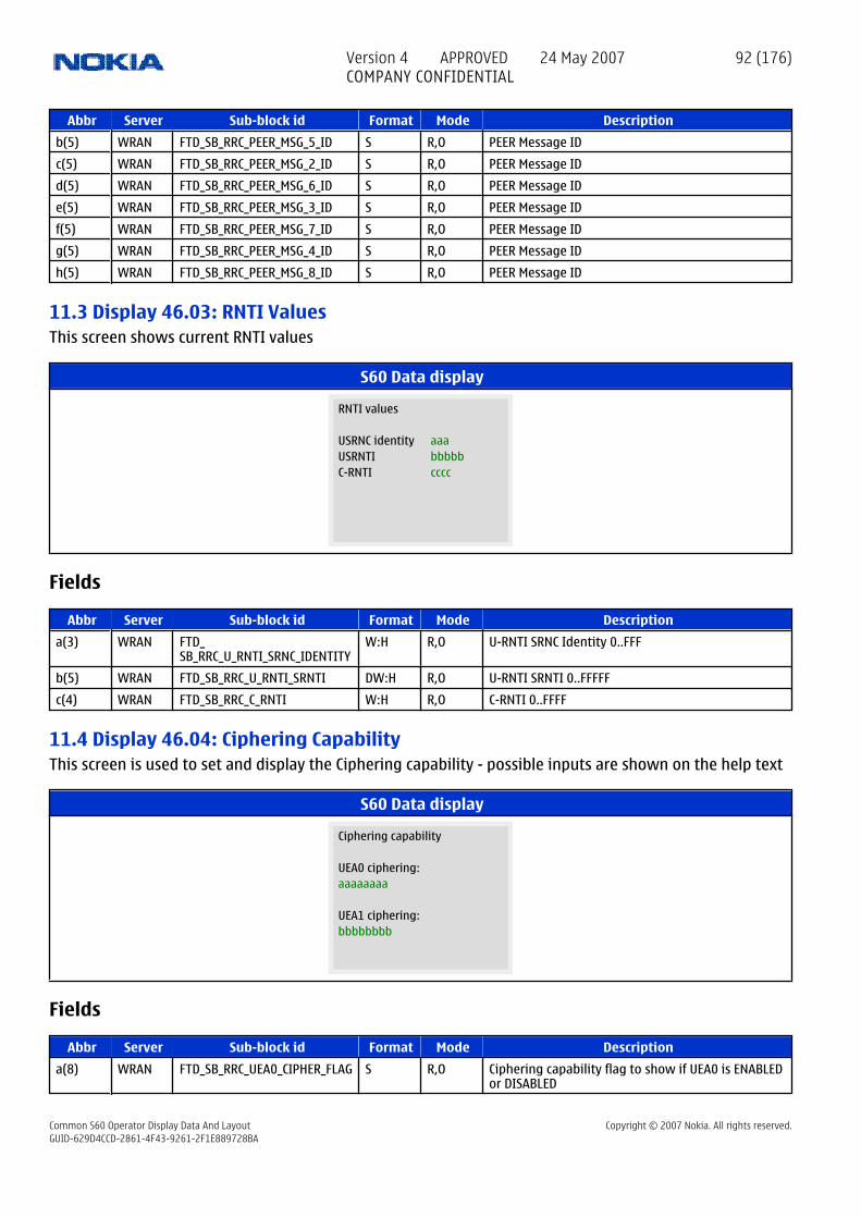
Abbr Server Sub-block id Format Mode Description
b(5) WRAN FTD_SB_RRC_PEER_MSG_5_ID S R,O PEER Message ID
c(5) WRAN FTD_SB_RRC_PEER_MSG_2_ID S R,O PEER Message ID
d(5) WRAN FTD_SB_RRC_PEER_MSG_6_ID S R,O PEER Message ID
e(5) WRAN FTD_SB_RRC_PEER_MSG_3_ID S R,O PEER Message ID
f(5) WRAN FTD_SB_RRC_PEER_MSG_7_ID S R,O PEER Message ID
g(5) WRAN FTD_SB_RRC_PEER_MSG_4_ID S R,O PEER Message ID
h(5) WRAN FTD_SB_RRC_PEER_MSG_8_ID S R,O PEER Message ID
11.3 Display 46.03: RNTI ValuesThis screen shows current RNTI values
S60 Data display
aaa
C-RNTI
RNTI values
bbbbbUSRNC identity
ccccUSRNTI
Fields
Abbr Server Sub-block id Format Mode Description
a(3) WRAN FTD_ SB_RRC_U_RNTI_SRNC_IDENTITY
W:H R,O U-RNTI SRNC Identity 0..FFF
b(5) WRAN FTD_SB_RRC_U_RNTI_SRNTI DW:H R,O U-RNTI SRNTI 0..FFFFF
c(4) WRAN FTD_SB_RRC_C_RNTI W:H R,O C-RNTI 0..FFFF
11.4 Display 46.04: Ciphering CapabilityThis screen is used to set and display the Ciphering capability - possible inputs are shown on the help text
S60 Data display
aaaaaaaa
UEA1 ciphering:
Ciphering capability
bbbbbbbb
UEA0 ciphering:
Fields
Abbr Server Sub-block id Format Mode Description
a(8) WRAN FTD_SB_RRC_UEA0_CIPHER_FLAG S R,O Ciphering capability flag to show if UEA0 is ENABLEDor DISABLED
Version 4 APPROVED 24 May 2007COMPANY CONFIDENTIAL
92 (176)
Common S60 Operator Display Data And Layout Copyright © 2007 Nokia. All rights reserved.GUID-629D4CCD-2861-4F43-9261-2F1E889728BA

Abbr Server Sub-block id Format Mode Description
b(8) WRAN FTD_SB_RRC_UEA1_CIPHER_FLAG S R,O Ciphering capability flag to show if UEA1 is ENABLEDor DISABLED
INPUT WRAN FTD_ SB_INPUT_rrc_ftd_flag_uea_ciphering_capability
DW:D R,O callback function subblock identity
11.5 Display 46.05: Cell Selection - Screen 2This screen shows the current PLMN information
S60 Data display
aaaaaa
PLMN scramb code
Cell selection - 2
bbbbbbPLMN number
ccccccSearch type
dddddTrigger type
eeePLMN frequency
Fields
Abbr Server Sub-block id Format Mode Description
a(6) WRAN FTD_SB_RRC_PLMN_NUMBER DW:H R,O PLMN Number - 0..FFFFFF
b(6) WRAN FTD_ SB_RRC_PLMN_SEARCH_TYPE
S R,O Type of search used to find PLMN nonini, init, candid,allcel, emerge, PLMN
c(6) WRAN FTD_ SB_RRC_PLMN_SEARCH_TRIGGER
S R,O Type of trigger used to find PLMN - L1trig, statch,intRat
d(5) WRAN FTD_SB_RRC_PLMN_FREQ W:D R,O PLMN frequeny
e(3) WRAN FTD_SB_RRC_PLMN_SCR_CODE W:D R,O PLMN scramble code
11.6 Display 46.06: FDD BTS Carrier Lock ModeThis screen is used in BTS carrier lock mode to retrieve FDD Frequency and Scrambling code. The frequencyand scrambling code is entered as one decimal value. Both frequency and scrambling code are five digits.e.g. entered value on FTD is '1060000040', where '10600' is the BTS test frequency and '00040' is the testscrambling code. To clear the BTS test mode user enters '0000000000'.
S60 Data display
aaaaaFDD frequency:
FDD scrambling code:
FDD BTS carrier lock
bbbbb
mode
Version 4 APPROVED 24 May 2007COMPANY CONFIDENTIAL
93 (176)
Common S60 Operator Display Data And Layout Copyright © 2007 Nokia. All rights reserved.GUID-629D4CCD-2861-4F43-9261-2F1E889728BA

Fields
Abbr Server Sub-block id Format Mode Description
a(5) WRAN FTD_ SB_RRC_BTS_CARRIER_LOCK_FREQ
W:D R,O FDD Frequency to use in BTS carrier lock mode
b(5) WRAN FTD_ SB_RRC_BTS_CARRIER_LOCK_SCR_CODE
W:D R,O FDD scrambling code to use in BTS carrier lock mode
INPUT(10)
WRAN FTD_ SB_INPUT_rrc_ftd_wcdma_bts_freq_lock_mode
DW:D R,O callback function subblock identity
11.7 Display 46.07: Counter ResetThis screen is used to reset counters
S60 Data display
Counter reset
Reset all counters 1
Fields
Abbr Server Sub-block id Format Mode Description
INPUT WRAN FTD_ SB_INPUT_rrc_ftd_reset_counters
DW:D R,O callback function subblock identity
11.8 Display 46.08: Call Failure ReasonsThis screen shows Counts for each call failure reason
S60 Data display
aaa
OoS Unspec
Call failure
bbb
reason
cccRLink
dddHandover
eeeRLC
fffUplayer
gggNormal
hhhRLC/SIB7
iiiConfig
jjjV/N300
kkkCRT
lllV/N300
Version 4 APPROVED 24 May 2007COMPANY CONFIDENTIAL
94 (176)
Common S60 Operator Display Data And Layout Copyright © 2007 Nokia. All rights reserved.GUID-629D4CCD-2861-4F43-9261-2F1E889728BA

Fields
Abbr Server Sub-block id Format Mode Description
a(3) WRAN FTD_ SB_RRC_RADIO_LINK_FAILURE_COUNT
W:D R,O Number of Radio link Failures
b(3) WRAN FTD_ SB_RRC_HO_FROM_UTRAN_COUNT
W:D R,O Number of Handover to UTRAN
c(3) WRAN FTD_ SB_RRC_RLC_LINK_ERROR_COUNT
W:D R,O Number of RLC link Error
d(3) WRAN FTD_ SB_RRC_RELEASE_REQ_COUNT
W:D R,O Number of upper layer triggered release
e(3) WRAN FTD_ SB_RRC_NORMAL_REL_COUNT
W:D R,O Number of normal release
f(3) WRAN FTD_ SB_RRC_SIB7_RECEPTION_FAIL_COUNT
W:D R,O Number of RLC link Error
g(3) WRAN FTD_ SB_RRC_CONFIG_FAILURE_COUNT
W:D R,O Number of configuration failures
h(3) WRAN FTD_ SB_RRC_V300_GR_N300_COUNT
W:D R,O Number of V300 > N300 failures
i(3) WRAN FTD_ SB_RRC_T314_T315_TIMEOUT_COUNT
W:D R,O Number of Connection Reestablishment TimersTimeouts failures-T314/T315
j(3) WRAN FTD_ SB_RRC_V302_GR_N302_COUNT
W:D R,O Number of V302 > N302 failures
k(3) WRAN FTD_ SB_RRC_T316_T317_T307_COUNT
W:D R,O Number of Out of Service Timer Timeout failures-T316/T317/T307
l(3) WRAN FTD_ SB_RRC_UNSPECIFIC_FAILURE_COUNT
W:D R,O Number of unspecific failures
11.9 Display 46.09: L1 StateThis screen shows L1 State
S60 Data display
a
DPCH state
L1 state
bPCCPCH state
cSCCPCH state
dRACH state
Fields
Abbr Server Sub-block id Format Mode Description
a WRAN FTD_SB_RRC_PCCPCH_STATE B:D R,O PCCPCH State
Version 4 APPROVED 24 May 2007COMPANY CONFIDENTIAL
95 (176)
Common S60 Operator Display Data And Layout Copyright © 2007 Nokia. All rights reserved.GUID-629D4CCD-2861-4F43-9261-2F1E889728BA

Abbr Server Sub-block id Format Mode Description
b WRAN FTD_SB_RRC_SCCPCH_STATE B:D R,O SCCPCH State
c WRAN FTD_SB_RRC_RACH_STATE B:D R,O RACH State
d WRAN FTD_SB_RRC_DPCH_STATE B:D R,O DPCH State
11.10 Display 46.10: Cell Reselection - Screen 1This screen shows reselection OK and Fail counters
S60 Data display
aaaaa
OK / Failed
Cell reselection - 1
bbbbbIdle
ccccc
OK / Failed
dddddConnected
eeeee
OK / Failed
fffffUMTS=>GSM
ggggg
OK / Failed
hhhhhGSM=>UMTS
Fields
Abbr Server Sub-block id Format Mode Description
a(5) WRAN FTD_ SB_RRC_IDLE_RESELECTION_OK_COUNT
W:D R,O Number of successful Idle mode reselections
b(5) WRAN FTD_ SB_RRC_IDLE_RESELECTION_FAIL_COUNT
W:D R,O Number of unsuccessful Idle mode reselections
c(5) WRAN FTD_ SB_RRC_CON_RESELECTION_OK_COUNT
W:D R,O Number of successful Connected mode reselections
d(5) WRAN FTD_ SB_RRC_CON_RESELECTION_FAIL_COUNT
W:D R,O Number of unsuccessful Connected mode reselections
e(5) WRAN FTD_ SB_RRC_UMTS_TO_GSM_OK_COUNT
W:D R,O Number of successful UMTS to GSM reselections
f(5) WRAN FTD_ SB_RRC_UMTS_TO_GSM_FAIL_COUNT
W:D R,O Number of unsuccessful UMTS to GSM reselections
g(5) WRAN FTD_ SB_RRC_GSM_TO_UMTS_OK_COUNT
W:D R,O Number of successful GSM to UMTS reselections
h(5) WRAN FTD_ SB_RRC_GSM_TO_UMTS_FAIL_COUNT
W:D R,O Number of unsuccessful GSM to UMTS reselections
11.11 Display 46.11: Radio Access Bearer InformationThis screen shows Radio Access Bearers currently setup
Version 4 APPROVED 24 May 2007COMPANY CONFIDENTIAL
96 (176)
Common S60 Operator Display Data And Layout Copyright © 2007 Nokia. All rights reserved.GUID-629D4CCD-2861-4F43-9261-2F1E889728BA

S60 Data display
aaa
RAB information
bRAB ID
ccc
Domain
d
SRB's ID
eee fggg hiii jkkk l
mm nn oo pp
Fields
Abbr Server Sub-block id Format Mode Description
a(3) WRAN FTD_SB_RRC_RAB_ID1 B:D R,O Radio Access Bearer ID
b WRAN FTD_SB_RRC_RAB_ID1_DOMAIN S R,O Domain - PS, CS
c(3) WRAN FTD_SB_RRC_RAB_ID2 B:D R,O Radio Access Bearer ID
d WRAN FTD_SB_RRC_RAB_ID2_DOMAIN S R,O Domain - PS, CS
e(3) WRAN FTD_SB_RRC_RAB_ID3 B:D R,O Radio Access Bearer ID
f WRAN FTD_SB_RRC_RAB_ID3_DOMAIN S R,O Domain - PS, CS
g(3) WRAN FTD_SB_RRC_RAB_ID4 B:D R,O Radio Access Bearer ID
h WRAN FTD_SB_RRC_RAB_ID4_DOMAIN S R,O Domain - PS, CS
i(3) WRAN FTD_SB_RRC_RAB_ID5 B:D R,O Radio Access Bearer ID
j WRAN FTD_SB_RRC_RAB_ID5_DOMAIN S R,O Domain - PS, CS
k(3) WRAN FTD_SB_RRC_RAB_ID6 B:D R,O Radio Access Bearer ID
l WRAN FTD_SB_RRC_RAB_ID6_DOMAIN S R,O Domain - PS, CS
m(2) WRAN FTD_SB_RRC_SRB_ID1 B:D R,O Signalling Radio Bearer ID
n(2) WRAN FTD_SB_RRC_SRB_ID2 B:D R,O Signalling Radio Bearer ID
o(2) WRAN FTD_SB_RRC_SRB_ID3 B:D R,O Signalling Radio Bearer ID
p(2) WRAN FTD_SB_RRC_SRB_ID4 B:D R,O Signalling Radio Bearer ID
11.12 Display 46.12: Radio Bearer InformationThis screen shows all Radio Bearers associated with a RAB id. The RAB id and the associated domain areentered as a single decimal value. The RAB id is the first three digits and the domain is input as the last digit,1 for PS and 0 for CS.
S60 Data display
aaa
RB information - 1
bRAB ID and domain(P/C):
ccRadio Bearer ID
ddRe-establish tmr
ee ff gg hh ii jj
kkkkk
Version 4 APPROVED 24 May 2007COMPANY CONFIDENTIAL
97 (176)
Common S60 Operator Display Data And Layout Copyright © 2007 Nokia. All rights reserved.GUID-629D4CCD-2861-4F43-9261-2F1E889728BA

Fields
Abbr Server Sub-block id Format Mode Description
a(3) WRAN FTD_SB_RRC_RAB_ID B:D R,O Radio Access Bearer ID
b WRAN FTD_SB_RRC_RAB_ID_DOMAIN S R,O Domain - PS, CS
c(2) WRAN FTD_SB_RRC_RB_ID1 B:D R,O Radio Bearer ID
d(2) WRAN FTD_SB_RRC_RB_ID2 B:D R,O Radio Bearer ID
e(2) WRAN FTD_SB_RRC_RB_ID3 B:D R,O Radio Bearer ID
f(2) WRAN FTD_SB_RRC_RB_ID4 B:D R,O Radio Bearer ID
g(2) WRAN FTD_SB_RRC_RB_ID5 B:D R,O Radio Bearer ID
h(2) WRAN FTD_SB_RRC_RB_ID6 B:D R,O Radio Bearer ID
i(2) WRAN FTD_SB_RRC_RB_ID7 B:D R,O Radio Bearer ID
j(2) WRAN FTD_SB_RRC_RB_ID8 B:D R,O Radio Bearer ID
k(5) WRAN FTD_SB_RRC_RAB_RE_EST_TIMER S R,O Radio Access Bearer Re-establishment Timer (T314/T315)
INPUT(4) WRAN FTD_ SB_INPUT_rrc_ftd_rab_id_set
DW:D R,O callback function subblock identity
11.13 Display 46.13: Radio Bearer InformationThis screen takes an input Radio Bearer id and shows associated information
S60 Data display
aa
RB status
RB information - 2
bbbbb
RB ID:
cccccDomain
dddddRe-establishment
Fields
Abbr Server Sub-block id Format Mode Description
a(2) WRAN FTD_SB_RRC_RB_ID B:D R,O Radio Bearer ID
b(5) WRAN FTD_SB_RRC_RB_DOMAIN S R,O Domain - PS, CS, SRB
c(5) WRAN FTD_SB_RRC_RB_RE_EST_TIMER S R,O Radio Bearer Re-establishment Timer (T314/T315)
d(5) WRAN FTD_SB_RRC_RB_STATUS S R,O RB Status - Start, Stop
INPUT(2) WRAN FTD_SB_INPUT_rrc_ftd_rb_id_set DW:D R,O callback function subblock identity
Version 4 APPROVED 24 May 2007COMPANY CONFIDENTIAL
98 (176)
Common S60 Operator Display Data And Layout Copyright © 2007 Nokia. All rights reserved.GUID-629D4CCD-2861-4F43-9261-2F1E889728BA

12 Group 47: WCDMA RRC displays
12.1 Display 47.01: RRC Global State Change CountersThis screen shows Global RRC state Change Countes
S60 Data display
aaaaa
DCH=>CELL_PCHDCH=>URA_PCH
RRC global state change
bbbbb
counters
ccccc
DCH=>FACH
ddddd
FACH=>DCH
eeeee
FACH=>CELL_PCH
fffff
FACH=>URA_PCH
Fields
Abbr Server Sub-block id Format Mode Description
a(5) WRAN FTD_ SB_RRC_DCH_TO_FACH_COUNT
W:D R,O Number of state changes from DCH to FACH
b(5) WRAN FTD_ SB_RRC_FACH_TO_DCH_COUNT
W:D R,O Number of state changes from FACH to DCH
c(5) WRAN FTD_ SB_RRC_FACH_TO_CELLPCH_COUNT
W:D R,O Number of state changes from FACH to CELL_PCH
d(5) WRAN FTD_ SB_RRC_FACH_TO_URAPCH_COUNT
W:D R,O Number of state changes from FACH to URA_PCH
e(5) WRAN FTD_ SB_RRC_DCH_TO_CELLPCH_COUNT
W:D R,O Number of state changes from DCH to CELL_PCH
f(5) WRAN FTD_ SB_RRC_DCH_TO_URAPCH_COUNT
W:D R,O Number of state changes from DCH to URA_PCH
12.2 Display 47.02: Counters for Timeouts - Screen 1This screen shows the number timeouts for RRC timers
S60 Data display
aaa
RRC count timeouts - 1
bbbT300 T312
cccT301 T302
ddd
T304 T305eee
T307 T308fff
T309
ggg hhh
iii
Version 4 APPROVED 24 May 2007COMPANY CONFIDENTIAL
99 (176)
Common S60 Operator Display Data And Layout Copyright © 2007 Nokia. All rights reserved.GUID-629D4CCD-2861-4F43-9261-2F1E889728BA

Fields
Abbr Server Sub-block id Format Mode Description
a(3) WRAN FTD_ SB_RRC_T300_IDLE_TIMEOUT_COUNT
W:D R,O T300 timeout counter
b(3) WRAN FTD_ SB_RRC_T312_IDLE_TIMEOUT_COUNT
W:D R,O T312 timeout counter
c(3) WRAN FTD_ SB_RRC_T301_TIMEOUT_COUNT
W:D R,O T301 timeout counter
d(3) WRAN FTD_ SB_RRC_T302_TIMEOUT_COUNT
W:D R,O T302 timeout counter
e(3) WRAN FTD_ SB_RRC_T304_TIMEOUT_COUNT
W:D R,O T304 timeout counter
f(3) WRAN FTD_ SB_RRC_T305_TIMEOUT_COUNT
W:D R,O T305 timeout counter
g(3) WRAN FTD_ SB_RRC_T307_TIMEOUT_COUNT
W:D R,O T307 timeout counter
h(3) WRAN FTD_ SB_RRC_T308_TIMEOUT_COUNT
W:D R,O T308 timeout counter
i(3) WRAN FTD_ SB_RRC_T309_TIMEOUT_COUNT
W:D R,O T309 timeout counter
12.3 Display 47.03: Counters for Timeouts - Screen 2This screen shows the number timeouts for RRC timers
S60 Data display
aaa
RRC count timeouts - 2
bbbT310 T311
cccT312 T313
ddd
T314 T315eee
T316 T317fff ggg hhh
Fields
Abbr Server Sub-block id Format Mode Description
a(3) WRAN FTD_ SB_RRC_T310_TIMEOUT_COUNT
W:D R,O T310 timeout counter
b(3) WRAN FTD_ SB_RRC_T311_TIMEOUT_COUNT
W:D R,O T311 timeout counter
c(3) WRAN FTD_ SB_RRC_T312_TIMEOUT_COUNT
W:D R,O T312 timeout counter
d(3) WRAN FTD_ SB_RRC_T313_TIMEOUT_COUNT
W:D R,O T313 timeout counter
e(3) WRAN FTD_ SB_RRC_T314_TIMEOUT_COUNT
W:D R,O T314 timeout counter
f(3) WRAN FTD_ SB_RRC_T315_TIMEOUT_COUNT
W:D R,O T315 timeout counter
Version 4 APPROVED 24 May 2007COMPANY CONFIDENTIAL
100 (176)
Common S60 Operator Display Data And Layout Copyright © 2007 Nokia. All rights reserved.GUID-629D4CCD-2861-4F43-9261-2F1E889728BA

Abbr Server Sub-block id Format Mode Description
g(3) WRAN FTD_ SB_RRC_T316_TIMEOUT_COUNT
W:D R,O T316 timeout counter
h(3) WRAN FTD_ SB_RRC_T317_TIMEOUT_COUNT
W:D R,O T317 timeout counter
12.4 Display 47.04: Peer Message Count- Screen1This screen shows Count for Peer Messages
S60 Data display
aaa
SIB8
Peer message count - 1
bbbMIBccc
PMIBdddSIB1
eeeSIB2
fffSIB3ggg
PSIB3hhhSIB4
iiiPSIB4
jjjSIB5kkk
SIB6lllSIB7
Fields
Abbr Server Sub-block id Format Mode Description
a(3) WRAN FTD_SB_RRC_MIB_COUNT W:D R,O MIB Message Count
b(3) WRAN FTD_SB_RRC_PMIB_COUNT W:D R,O MIB Message Count
c(3) WRAN FTD_SB_RRC_SIB1_COUNT W:D R,O SIB1 Message Count
d(3) WRAN FTD_SB_RRC_SIB2_COUNT W:D R,O SIB2 Message Count
e(3) WRAN FTD_SB_RRC_SIB3_COUNT W:D R,O SIB3 Message Count
f(3) WRAN FTD_SB_RRC_PSIB3_COUNT W:D R,O SIB3 Message Count
g(3) WRAN FTD_SB_RRC_SIB4_COUNT W:D R,O SIB4 Message Count
h(3) WRAN FTD_SB_RRC_PSIB4_COUNT W:D R,O SIB4 Message Count
i(3) WRAN FTD_SB_RRC_SIB5_COUNT W:D R,O SIB5 Message Count
j(3) WRAN FTD_SB_RRC_SIB6_COUNT W:D R,O SIB6 Message Count
k(3) WRAN FTD_SB_RRC_SIB7_COUNT W:D R,O SIB7 Message Count
l(3) WRAN FTD_SB_RRC_SIB8_COUNT W:D R,O SIB8 Message Count
12.5 Display 47.05: Peer Message Count- Screen2This screen shows Peer Message Count
S60 Data display
aaa
SIB14
Peer message count - 2
bbbSIB9
ccc
SIB15
ddd
SIB10
eee
SIB16
fff
SIB11
ggg
SIB17hhh
SIB12iii
SIB18 jjjSIB13
Version 4 APPROVED 24 May 2007COMPANY CONFIDENTIAL
101 (176)
Common S60 Operator Display Data And Layout Copyright © 2007 Nokia. All rights reserved.GUID-629D4CCD-2861-4F43-9261-2F1E889728BA

Fields
Abbr Server Sub-block id Format Mode Description
a(3) WRAN FTD_SB_RRC_SIB9_COUNT W:D R,O SIB9 Message Count
b(3) WRAN FTD_SB_RRC_SIB10_COUNT W:D R,O SIB10 Message Count
c(3) WRAN FTD_SB_RRC_SIB11_COUNT W:D R,O SIB11 Message Count
d(3) WRAN FTD_SB_RRC_SIB12_COUNT W:D R,O SIB12 Message Count
e(3) WRAN FTD_SB_RRC_SIB13_COUNT W:D R,O SIB13 Message Count
f(3) WRAN FTD_SB_RRC_SIB14_COUNT W:D R,O SIB14 Message Count
g(3) WRAN FTD_SB_RRC_SIB15_COUNT W:D R,O SIB15 Message Count
h(3) WRAN FTD_SB_RRC_SIB16_COUNT W:D R,O SIB16 Message Count
i(3) WRAN FTD_SB_RRC_SIB17_COUNT W:D R,O SIB17 Message Count
j(3) WRAN FTD_SB_RRC_SIB18_COUNT W:D R,O SIB18 Message Count
12.6 Display 47.06: Peer Message Count-Screen3This screen shows Peer Message Count
S60 Data display
aaa
Paging type2
Peer message count - 3
bbbConnect request
cccConnect reject
dddConnect setup
eeeConnect setup compl
fffConnect release
gggConnect rel compl
hhhPaging type1
Fields
Abbr Server Sub-block id Format Mode Description
a(3) WRAN FTD_SB_RRC_CONRQ_COUNT W:D R,O RRC Connection Request Message Count
b(3) WRAN FTD_SB_RRC_CONREJ_COUNT W:D R,O RRC Connection Reject Message Count
c(3) WRAN FTD_SB_RRC_CONSET_COUNT W:D R,O RRC Connection Setup Message Count
d(3) WRAN FTD_SB_RRC_CONSC_COUNT W:D R,O RRC Connection Setup Complete Message Count
e(3) WRAN FTD_SB_RRC_CONREL_COUNT W:D R,O RRC Connection Release Message Count
f(3) WRAN FTD_SB_RRC_CNRLC_COUNT W:D R,O RRC Connection Release Complete Message Count
g(3) WRAN FTD_SB_RRC_PAGE1_COUNT W:D R,O Paging Type1 Message Count
h(3) WRAN FTD_SB_RRC_PAGE2_COUNT W:D R,O Paging Type2 Message Count
12.7 Display 47.07: Peer Message Count-Screen4This screen shows Peer Message Count
Version 4 APPROVED 24 May 2007COMPANY CONFIDENTIAL
102 (176)
Common S60 Operator Display Data And Layout Copyright © 2007 Nokia. All rights reserved.GUID-629D4CCD-2861-4F43-9261-2F1E889728BA

S60 Data display
aaa
Peer message count - 4
bbbRB setup
cccok / fail
dddRB reconf
eeeok / fail
fffRB release
gggok / failhhh
Transport CHiii
ok / failjjj kkk lll
Fields
Abbr Server Sub-block id Format Mode Description
a(3) WRAN FTD_SB_RRC_RBSET_COUNT W:D R,O Radio Bearer Setup Message Count
b(3) WRAN FTD_SB_RRC_RBSTC_COUNT W:D R,O Radio Bearer Setup Complete Message Count
c(3) WRAN FTD_SB_RRC_RBSTF_COUNT W:D R,O Radio Bearer Setup Failure Message Count
d(3) WRAN FTD_SB_RRC_RBRC_COUNT W:D R,O Radio Bearer Reconfiguration Message Count
e(3) WRAN FTD_SB_RRC_RBRCC_COUNT W:D R,O Radio Bearer Reconfiguration Complete MessageCount
f(3) WRAN FTD_SB_RRC_RBRCF_COUNT W:D R,O Radio Bearer Reconfiguration Failure Message Count
g(3) WRAN FTD_SB_RRC_RBRL_COUNT W:D R,O Radio Bearer Release Message Count
h(3) WRAN FTD_SB_RRC_RBRLC_COUNT W:D R,O Radio Bearer Release Complete Message Count
i(3) WRAN FTD_SB_RRC_RBRLF_COUNT W:D R,O Radio Bearer Release Failure Message Count
j(3) WRAN FTD_SB_RRC_TCR_COUNT W:D R,O Transport Channel Reconfiguration Message Count
k(3) WRAN FTD_SB_RRC_TCHRC_COUNT W:D R,O Transport Channel Reconfiguration CompleteMessage Count
l(3) WRAN FTD_SB_RRC_TCHRF_COUNT W:D R,O Transport Channel Reconfiguration Failure MessageCount
12.8 Display 47.08: Peer Message Count-Screen5This screen shows Peer Message Count
S60 Data display
aaa
Peer message count - 5
bbbPhysical CH
cccok / fail
dddAct set update
eeeok / fail
fffHO to UTRAN
gggok / failhhh
HO from UTRANiii
jjj
Fields
Abbr Server Sub-block id Format Mode Description
a(3) WRAN FTD_SB_RRC_PCRC_COUNT W:D R,O Physical Channel Reconfiguration Message Count
b(3) WRAN FTD_SB_RRC_PCHRC_COUNT W:D R,O Physical Channel Reconfiguration Complete MessageCount
Version 4 APPROVED 24 May 2007COMPANY CONFIDENTIAL
103 (176)
Common S60 Operator Display Data And Layout Copyright © 2007 Nokia. All rights reserved.GUID-629D4CCD-2861-4F43-9261-2F1E889728BA

Abbr Server Sub-block id Format Mode Description
c(3) WRAN FTD_SB_RRC_PCHRF_COUNT W:D R,O Physical Channel Reconfiguration Failure MessageCount
d(3) WRAN FTD_SB_RRC_ASUP_COUNT W:D R,O Active Set Update Message Count
e(3) WRAN FTD_SB_RRC_ASUPC_COUNT W:D R,O Active Set Update Complete Message Count
f(3) WRAN FTD_SB_RRC_ASUPF_COUNT W:D R,O Active Set Update Failure Message Count
g(3) WRAN FTD_SB_RRC_HOTUT_COUNT W:D R,O Handover to UTRAN Message Count
h(3) WRAN FTD_SB_RRC_HOTUC_COUNT W:D R,O Handover to UTRAN Complete Message Count
i(3) WRAN FTD_SB_RRC_HFUG_COUNT W:D R,O Handover from UTRAN Message Count
j(3) WRAN FTD_SB_RRC_HOFUF_COUNT W:D R,O Handover from UTRAN Failure Message Count
12.9 Display 47.09: Peer Message Count-Screen6This screen shows Peer Message count
S60 Data display
aaa
SecModFail
Peer message count - 6
bbbCUcccCU confirm
dddCountChkeee
IDTfffDL_tr
gggUL_tr
hhhMContriii
MCFailjjjMRep
kkkSecMod
lllSecModComp
Fields
Abbr Server Sub-block id Format Mode Description
a(3) WRAN FTD_SB_RRC_CELUP_COUNT W:D R,O Cell Update Message Count
b(3) WRAN FTD_SB_RRC_CUCNF_COUNT W:D R,O Cell Update Confirm Message Count
c(3) WRAN FTD_SB_RRC_CTCK_COUNT W:D R,O Counter Check Message Count
d(3) WRAN FTD_SB_RRC_IDT_COUNT W:D R,O Initial Direct Transfer Message Count
e(3) WRAN FTD_SB_RRC_DDT_COUNT W:D R,O Downlink Direct Transfer Message Count
f(3) WRAN FTD_SB_RRC_UDT_COUNT W:D R,O Uplink Direct Transfer Message Count
g(3) WRAN FTD_SB_RRC_MECON_COUNT W:D R,O Measurement Control Message Count
h(3) WRAN FTD_SB_RRC_MECOF_COUNT W:D R,O Measurement Control Failure Message Count
i(3) WRAN FTD_SB_RRC_MEREP_COUNT W:D R,O Measurement Report Message Count
j(3) WRAN FTD_SB_RRC_SECM_COUNT W:D R,O Security Mode Command Message Count
k(3) WRAN FTD_SB_RRC_SECMC_COUNT W:D R,O Security Mode Complete Message Count
l(3) WRAN FTD_SB_RRC_SECMF_COUNT W:D R,O Security Mode Failure Message Count
12.10 Display 47.10: Peer Message Count-Screen7This screen shows Peer Message Count
Version 4 APPROVED 24 May 2007COMPANY CONFIDENTIAL
104 (176)
Common S60 Operator Display Data And Layout Copyright © 2007 Nokia. All rights reserved.GUID-629D4CCD-2861-4F43-9261-2F1E889728BA

S60 Data display
aaa
Peer message count - 7
bbbSG_CR mes/indcccUE_CE URA ddd
RRC URA_conf eeeUTRAN UTRAN_cf
fff
UTRAN_failggg
CCO_from_UTRAN
hhh
CCO_from_UTRAN_Fail
iiijjjkkk
Fields
Abbr Server Sub-block id Format Mode Description
a(3) WRAN FTD_SB_RRC_SGCR_COUNT W:D R,O Signalling Connection Release Message Count
b(3) WRAN FTD_SB_RRC_SGCRI_COUNT W:D R,O Signalling Connection Release Indication MessageCount
c(3) WRAN FTD_SB_RRC_UECEQ_COUNT W:D R,O UE Capability Enquiry Message Count
d(3) WRAN FTD_SB_RRC_URAUP_COUNT W:D R,O URA Update Message Count
e(3) WRAN FTD_SB_RRC_RRCST_COUNT W:D R,O RRC Status Message Count
f(3) WRAN FTD_SB_RRC_URAUC_COUNT W:D R,O URA Update Confirm Message Count
g(3) WRAN FTD_SB_RRC_UTMI_COUNT W:D R,O UTRAN Mobility Information Message Count
h(3) WRAN FTD_SB_RRC_UMIC_COUNT W:D R,O UTRAN Mobility Information Confirm Message Count
i(3) WRAN FTD_SB_RRC_UMIF_COUNT W:D R,O UTRAN Mobility Information Failure Message Count
j(3) WRAN FTD_SB_RRC_CCOFU_COUNT W:D R,O CellChangeOrderFromUTRAN message Count
k(3) WRAN FTD_SB_RRC_CCOFUF_COUNT W:D R,O CellChangeOrderFromUTRANFailure message Count
12.11 Display 47.11: FDD HSDPAThis display shows the HSDPA L3 Indentifier information
S60 Data display
aaaaaSCR
HSDPA Identifier
bbbbbHRNTI
Fields
Abbr Server Sub-block id Format Mode Description
a(5) WRAN FTD_SB_HSDPA_H_RNTI W:D R,I,O Network assigned H_RNTI
b(5) WRAN FTD_ SB_HSDPA_PRIMARY_SCR_CODE
W:D R,I,O Scrambling code for HSDPA serving RL
12.12 Display 47.12: FDD HSDPAThis display shows HSDPA L3 HS_SCCH information
Version 4 APPROVED 24 May 2007COMPANY CONFIDENTIAL
105 (176)
Common S60 Operator Display Data And Layout Copyright © 2007 Nokia. All rights reserved.GUID-629D4CCD-2861-4F43-9261-2F1E889728BA

S60 Data display
aaaaa
Ch3Ch4
HSDPA HSSCCH
bbbbb
Channelisation Codes
ccccc
Ch1
ddddd
Ch2
Fields
Abbr Server Sub-block id Format Mode Description
a(5) WRAN FTD_ SB_HSDPA_HS_SCCH_CHANNELISATION_CODE1
W:D R,I,O HS_SCCH Channelisation Code 1
b(5) WRAN FTD_ SB_HSDPA_HS_SCCH_CHANNELISATION_CODE2
W:D R,I,O HS_SCCH Channelisation Code 2
c(5) WRAN FTD_ SB_HSDPA_HS_SCCH_CHANNELISATION_CODE3
W:D R,I,O HS_SCCH Channelisation Code 3
d(5) WRAN FTD_ SB_HSDPA_HS_SCCH_CHANNELISATION_CODE4
W:D R,I,O HS_SCCH Channelisation Code 4
12.13 Display 47.13: FDD HSDPAThis display shows HSDPA L3 Measurement Feedback Information
S60 Data display
aaaaaRepdCQI
Measurement
b
Feedback Info
c
Cycle
Fields
Abbr Server Sub-block id Format Mode Description
a(5) WRAN FTD_ SB_HSDPA_CQI_FEEDBACK_CYCLE
W:D R,I,O Actual value in milliseconds
b WRAN FTD_ SB_HSDPA_CQI_REPETITION_FACTOR
W:D R,I,O CQI Repetition factor
c WRAN FTD_SB_HSDPA_CQI_DELTA_CQI W:D R,I,O Delta CQI
12.14 Display 47.14: FDD HSDPAThis display shows HSDPA L3 HARQ Memory Partition Type Information
Version 4 APPROVED 24 May 2007COMPANY CONFIDENTIAL
106 (176)
Common S60 Operator Display Data And Layout Copyright © 2007 Nokia. All rights reserved.GUID-629D4CCD-2861-4F43-9261-2F1E889728BA

S60 Data display
aHQ MemType
Harq Memory Type
Fields
Abbr Server Sub-block id Format Mode Description
a WRAN FTD_ SB_HSDPA_HARQ_MEMORY_PARTITION_TYPE
W:D R,I,O HARQ Memory Partition Type0 =Implicit, 1 = Explicit
12.15 Display 47.15: FDD HSDPAThis display shows HSDPA L3 HARQ Memory Size Information - Processes 1 - 4
S60 Data display
aaaaaaaa
HQ3HQ4
Harq Memory
bbbbbbbb
Sizes 1 - 4
cccccccc
HQ1
dddddddd
HQ2
Fields
Abbr Server Sub-block id Format Mode Description
a(8) WRAN FTD_ SB_HSDPA_HARQ_MEMORY_SIZE_PROCESS1
DW:H R,I,O HARQ Memory Size
b(8) WRAN FTD_ SB_HSDPA_HARQ_MEMORY_SIZE_PROCESS2
DW:H R,I,O HARQ Memory Size
c(8) WRAN FTD_ SB_HSDPA_HARQ_MEMORY_SIZE_PROCESS3
DW:H R,I,O HARQ Memory Size
d(8) WRAN FTD_ SB_HSDPA_HARQ_MEMORY_SIZE_PROCESS4
DW:H R,I,O HARQ Memory Size
12.16 Display 47.16: FDD HSDPAThis display shows HSDPA L3 HARQ Memory Size Information - Processes 5 - 8
Version 4 APPROVED 24 May 2007COMPANY CONFIDENTIAL
107 (176)
Common S60 Operator Display Data And Layout Copyright © 2007 Nokia. All rights reserved.GUID-629D4CCD-2861-4F43-9261-2F1E889728BA

S60 Data display
aaaaaaaa
HQ7HQ8
Harq Memory
bbbbbbbb
Sizes 5 - 8
cccccccc
HQ5
dddddddd
HQ6
Fields
Abbr Server Sub-block id Format Mode Description
a(8) WRAN FTD_ SB_HSDPA_HARQ_MEMORY_SIZE_PROCESS5
DW:H R,I,O HARQ Memory Size
b(8) WRAN FTD_ SB_HSDPA_HARQ_MEMORY_SIZE_PROCESS6
DW:H R,I,O HARQ Memory Size
c(8) WRAN FTD_ SB_HSDPA_HARQ_MEMORY_SIZE_PROCESS7
DW:H R,I,O HARQ Memory Size
d(8) WRAN FTD_ SB_HSDPA_HARQ_MEMORY_SIZE_PROCESS8
DW:H R,I,O HARQ Memory Size
12.17 Display 47.17: FDD HSDPAThis display shows HSDPA L3 DPCH Power Control Information
S60 Data display
a
Rep
DPCH PwrCtrl
bdAck
cdNack
Fields
Abbr Server Sub-block id Format Mode Description
a WRAN FTD_ SB_HSDPA_DPCH_PWRCTRL_DELTA_ACK
W:D R,I,O DPCH Power Control - deltaAck value
b WRAN FTD_ SB_HSDPA_DPCH_PWRCTRL_DELTA_NACK
W:D R,I,O DPCH Power Control - deltaNack value
c WRAN FTD_ SB_HSDPA_DPCH_PWRCTRL_ACKNACK_REPETITION_FACTOR
W:D R,I,O DPCH Power Control - ACK/NACKRepetition Factor
Version 4 APPROVED 24 May 2007COMPANY CONFIDENTIAL
108 (176)
Common S60 Operator Display Data And Layout Copyright © 2007 Nokia. All rights reserved.GUID-629D4CCD-2861-4F43-9261-2F1E889728BA

13 Group 48: WCDMA RLC displays
13.1 Display 48.01: Set AM Bearer IDSet the RLC AM bearer ID for which the AM info will be displayed
S60 Data display
aa
RLC mode:
Set AM bearer ID
bbbbRadio bearer:
ccRLC SAP:
Fields
Abbr Server Sub-block id Format Mode Description
a(2) WRAN FTD_ SB_RLC_FTD_SELECTED_AM_RADIO_BEARER
B:D R,O AM radio bearer for which data is to be displayed. Itis uint8 data. It can be 1 - 32.
b(4) WRAN FTD_SB_RLC_FTD_SAP_USER S R,O RLC SAP user for selected radio bearer. It is string data.It can be "RRC" or "PDCP".
c(2) WRAN FTD_SB_RLC_FTD_MODE S R,O RLC mode for selected radio bearer. It is string data.It can be "AM" or "UM".
INPUT(2) WRAN FTD_ SB_INPUT_RLC_FTD_AM_BEARER_SELECT
DW:D R,O callback function subblock identity
13.2 Display 48.02: RLC AM State informationThis screen displays state information for the AM bearer selected using display 48.01
S60 Data display
aaaAM downlink status
RLC AM state info
bbbAM uplink status
Fields
Abbr Server Sub-block id Format Mode Description
a(3) WRAN FTD_ SB_RLC_FTD_AM_UL_FLOW_CTRL
S R,O AM Uplink flow control status. It is string data. It canbe "ON" or "OFF".
b(3) WRAN FTD_ SB_RLC_FTD_AM_DL_FLOW_CTRL
S R,O AM Downlink flow control status. It is string data. Itcan be "ON" or "OFF".
Version 4 APPROVED 24 May 2007COMPANY CONFIDENTIAL
109 (176)
Common S60 Operator Display Data And Layout Copyright © 2007 Nokia. All rights reserved.GUID-629D4CCD-2861-4F43-9261-2F1E889728BA

14 Group 75: Location Displays
14.1 Group 75 InformationLocation displays are grouped in the following way:
Displays 75.0X: Common location FTDs
Displays 75.2X: GSM specific General FTDs
Displays 75.3X: GPS specific General FTDs
14.2 Display 75.01: WGS-84 CoordinatesLocation displays are grouped in the following way:
This display shows latitude / longitude for the last requested location
NOTE!
All numerical values are shown in decimal.
In case no location request has been requested all fields shall show "x".
In case the latest received location request did not result in any latitude / longitude, these fields shall display"-", but method and status fields shall display actual values.
S60 Data display
aLATITUDE
bbLONGITUDE
cccccc
STATUSd
METHOD
eee ffffff
ggggggggggg
hhhhhhhhhhh
Fields
Abbr Server Sub-block id Format Mode Description
a LOCATION
LS_SB_FTD_LATITUDE_DIR S R,I,O Latitude direction: N : North, S : South
b(2) LOCATION
LS_SB_FTD_LATITUDE_DEG S R,I,O Latitude: degree
c(6) LOCATION
LS_SB_FTD_LATITUDE S R,I,O Latitude: decimal degrees
d LOCATION
LS_SB_FTD_LONGITUDE_DIR S R,I,O Longitude direction: E : East, W : West
e(3) LOCATION
LS_SB_FTD_LONGITUDE_DEG S R,I,O longitude: degrees
f(6) LOCATION
LS_SB_FTD_LONGITUDE S R,I,O longitude:decimal degrees
g(11) LOCATION
LS_ SB_FTD_LOCATE_RESP_STATUS
S R,I,O Status: OK: Successful location response DONE:Successful location response - last of multiple FAIL:Fatal error occurred, no location estimate TIME-OUT:Desired Response Time exceeded. PRIV-NOT-OK:Privacy not ok
Version 4 APPROVED 24 May 2007COMPANY CONFIDENTIAL
110 (176)
Common S60 Operator Display Data And Layout Copyright © 2007 Nokia. All rights reserved.GUID-629D4CCD-2861-4F43-9261-2F1E889728BA

Abbr Server Sub-block id Format Mode Description
h(11) LOCATION
LS_ SB_FTD_LOCATE_RESP_METHOD
S R,I,O Method: NW SELECT: The method is selected by theNW. AGPS, MS BAS: MS based AGPS method usedAGPS, MS ASS: MS assisted AGPS method used AFLT,MS BAS: MS based AFLT method used SECTOR: Brewsector information HYBRID: More than 1
14.3 Display 75.02: Altitude and Velocity vectorThis display shows altitude and velocity for the last requested location.
NOTE!
All numerical values are shown in decimal.
In case no location request has been requested all fields shall display "x".
In case the latest location estimate did not include altitude/velocity these fields shall display "-".
S60 Data display
aaaaaaSpeed(m/s)bbbbbHeading(deg)ccccccccAltitude(m)ddddddddddddFix Type
Fields
Abbr Server Sub-block id Format Mode Description
a(6) LOCATION
LS_SB_FTD_SPEED S R,I,O Speed in m/s. Format aaa.aa.
b(5) LOCATION
LS_SB_FTD_DIRECTION S R,I,O Heading in degrees relative to north (clockwise).Format bbb.b
c(8) LOCATION
LS_SB_FTD_ALTITUDE S R,I,O Altitude above WGS-84 ellipsoid in meters. Can benegative or positive (+/-). Format cccccc.c
d(12) LOCATION
LS_SB_FTD_FIX_TYPE S R,I,O Fix Type: 2D 2 dimensional fix 3D 3 dimensional fix
14.4 Display 75.03: Error Estimate EllipsoidThis display shows error estimation for the last requested location.
All numerical values are shown in decimal.
In case no location request has been requested all fields shall display "x".
In case the latest location estimate did not include uncertainty information these fields shall display "-".
Version 4 APPROVED 24 May 2007COMPANY CONFIDENTIAL
111 (176)
Common S60 Operator Display Data And Layout Copyright © 2007 Nokia. All rights reserved.GUID-629D4CCD-2861-4F43-9261-2F1E889728BA

S60 Data display
aaaOrientationbbbbbPerpendi.(m)cccccAlong (m)dddddVertical (m)
Fields
Abbr Server Sub-block id Format Mode Description
a(3) LOCATION
LS_SB_FTD_ERR_ORIENTAT S R,I,O Error estimate ellipsoid orientation clockwise fromnorth in degrees (0..89 degrees)
b(5) LOCATION
LS_SB_FTD_ERR_EAST S R,I,O Error estimate East in meters, 1 sigma value
c(5) LOCATION
LS_SB_FTD_ERR_NORTH S R,I,O Error estimate North in meters, 1 sigma value
d(5) LOCATION
LS_SB_FTD_ERR_VERT S R,I,O Error estimate Vertical in meters, 1 sigma value
14.5 Display 75.04: MS Time of the Location EstimateThis display shows the time stamp for the last location estimate .
The time stamp is always based on local time, i.e. the time of the clock in MS.
NOTE!
All numerical values are shown in decimal.
If MS time in ISA Time Server is not set one might experience invalid time stamps.
S60 Data display
aaaaaaaaaaMS DatebbbbbbbbMS TimecccccccccccSTATUS
Fields
Abbr Server Sub-block id Format Mode Description
a(10) LOCATION
LS_SB_FTD_MS_DATE S R,I,O MS date: (format: dd:mm:yyyy; dd day, mm month, yyyear)
b(8) LOCATION
LS_SB_FTD_MS_TIME S R,I,O MS Time: (format: hh:mm:ss; hh hours, mm minutes,ss seconds)
Version 4 APPROVED 24 May 2007COMPANY CONFIDENTIAL
112 (176)
Common S60 Operator Display Data And Layout Copyright © 2007 Nokia. All rights reserved.GUID-629D4CCD-2861-4F43-9261-2F1E889728BA

Abbr Server Sub-block id Format Mode Description
c(11) LOCATION
LS_ SB_FTD_LOCATE_RESP_STATUS
S R,I,O Status: OK: Successful location response DONE:Successful location response - last of multiple FAIL:Fatal error occurred, no location estimate TIME-OUT:Desired Response Time exceeded. PRIV-NOT-OK:Privacy not ok
14.6 Display 75.10: Test Display #1To start a location request, perform following steps:
1. Press the Menu button
2. Scroll in the main menu loop to field test display item
3. Press the Select button
4. Select this display in input mode by entering 75.10
5. "INPUT" prompt will be shown on the display, enter the location request parameters in display followingthis:L XYANNN
Value of L NMEA logfile handling (this only applies to S40products)
0 Logfile is not created in root directory of the memorycard
1 Logfile is created in root directory of the memorycard
Value of X Location method
0 Stand-Alone GPS
1 MS-Based AGPS
Value of Y Start type
0 Cold start (all GPS data cleared)
1 Warm start (GPS Ephemeris data cleared)
2 Hot start (no GPS data cleared)
Value of A Multiple request type
0 Multiple requests for single-fix. Request treated as NNN *single fix (e.g each can start as cold start)
1 Single request for multiple fixes. Request treated as 1 *multiple fixes (with NNN number of fixes, e.g. only first onecan start as cold start). The interval between the fixes willbe 1 second.
Value of NNN Number of fixes
000 Stop ongoing location request
Version 4 APPROVED 24 May 2007COMPANY CONFIDENTIAL
113 (176)
Common S60 Operator Display Data And Layout Copyright © 2007 Nokia. All rights reserved.GUID-629D4CCD-2861-4F43-9261-2F1E889728BA

XXX Number of fixes to be made (ranging in [001, FFE])
FFF Infinite number of fixes - continuous until stopped(NNN=000)
6. Confirm with the Ok button
If change succeeded the status will show appropriate value.
TTF (Time To Fix) will show the measured time to get the first fix only.
S60 Data display
aaaaaaaaaaaStatusbbbbbTTF(s)
Fields
Abbr Server Sub-block id Format Mode Description
a(11) LOCATION
LS_ SB_FTD_LOCATE_RESP_STATUS
S R,I,O Status: OK: Successful location response DONE:Successful location response - last of multiple FAIL:Fatal error occurred, no location estimate TIME-OUT:Desired Response Time exceeded. PRIV-NOT-OK:Privacy not ok
b(5) LOCATION
LS_SB_FTD_FIX_TIME S R,I,O Measured Time to fix (bbb.b) seconds
INPUT(7) LOCATION
LS_SB_FTD_LOCATION_REQ DW:H R,I,O Trigger location request xyannn
14.7 Display 75.11: Test Display #2This display is associated to 75.10.
When a location request is started from display 75.10, all fields in 75.11 will be cleared (set to zero, 000). IfNNN * single fixes was requested, Location Server will measure the actual time to each fix, and incrementthe appropriate counter by one.
S60 Data display
aaa<05 <10 <15
bbb<20 <25 <30
ccc
<35 <40 <45ddd
<50 <55 >55
eee fff
ggg hhh iii
jjj kkk lll
Version 4 APPROVED 24 May 2007COMPANY CONFIDENTIAL
114 (176)
Common S60 Operator Display Data And Layout Copyright © 2007 Nokia. All rights reserved.GUID-629D4CCD-2861-4F43-9261-2F1E889728BA

Fields
Abbr Server Sub-block id Format Mode Description
a(3) LOCATION
LS_SB_FTD_TTF_LESS_5 W:D R,I,O counter for fixes, TTF < 5s
b(3) LOCATION
LS_SB_FTD_TTF_LESS_10 W:D R,I,O counter for fixes, 5s=<TTF<10s
c(3) LOCATION
LS_SB_FTD_TTF_LESS_15 W:D R,I,O counter for fixes, 10s=<TTF<15s
d(3) LOCATION
LS_SB_FTD_TTF_LESS_20 W:D R,I,O counter for fixes, 15s=<TTF<20s
e(3) LOCATION
LS_SB_FTD_TTF_LESS_25 W:D R,I,O counter for fixes 20s=<TTF<25s
f(3) LOCATION
LS_SB_FTD_TTF_LESS_30 W:D R,I,O counter for fixes 25s=<TTF<30s
g(3) LOCATION
LS_SB_FTD_TTF_LESS_35 W:D R,I,O counter for fixes 30s=<TTF<35s
h(3) LOCATION
LS_SB_FTD_TTF_LESS_40 W:D R,I,O counter for fixes 35s=<TTF<40s
i(3) LOCATION
LS_SB_FTD_TTF_LESS_45 W:D R,I,O counter for fixes 40s=<TTF<45s
j(3) LOCATION
LS_SB_FTD_TTF_LESS_50 W:D R,I,O counter for fixes 45s=<TTF<50s
k(3) LOCATION
LS_SB_FTD_TTF_LESS_55 W:D R,I,O counter for fixes 50s=<TTF<55s
l(3) LOCATION
LS_SB_FTD_TTF_GREATER_55 W:D R,I,O counter for fixes 55s=<TTF
14.8 Display 75.20: GSM Location Request Counters, E-OTDNOTE!
Examples for how the counters should behave for display 75.20, 75.21 and 75.22 can be found together withdescription for display 75.22 (chapter 7.42.10).
S60 Data display
aaaaa
RESP FAIL
EOTD
bbbbbREQUESTS
cccccRESP OK
Fields
Abbr Server Sub-block id Format Mode Description
a(5) LOCATION
LS_SB_FTD_EOTD_REQS W:D R,I,O Received GSM Measure Position Request requiringlocation method E-OTD since power-up.
b(5) LOCATION
LS_SB_FTD_EOTD_OK W:D R,I,O E-OTD locations or measurements sent successfully toCS SW as a response to GSM Measure Position Requestwith requested method E-OTD since power-up.
Version 4 APPROVED 24 May 2007COMPANY CONFIDENTIAL
115 (176)
Common S60 Operator Display Data And Layout Copyright © 2007 Nokia. All rights reserved.GUID-629D4CCD-2861-4F43-9261-2F1E889728BA

Abbr Server Sub-block id Format Mode Description
c(5) LOCATION
LS_SB_FTD_EOTD_FAIL W:D R,I,O Responses to E-OTD GSM Position Request requestingthe method "E-OTD" that have contained GSMLocation Information error element since power-up.
14.9 Display 75.21: GSM Measure Position Request Counters, GPSSub-Group: GSM, General Location FTDs
NOTE!
The following shows some examples how the counters in the FTD should behave in different situations. Forthe examples the initial status for all counters is “0”.
Example Situation Display 75.21: GSM Measure Position RequestCounters, GPS (Status: Proposal)
Measure Position Request with the required method 'GPS'and successful GPS measurement
+++++++++++++++ GPS ++ REQ 1++ OK 1++ FAIL 0+++++++++++++++
Measure Position Request with the required method 'GPS'and failed GPS measurement
+++++++++++++++ GPS ++ REQ 1++ OK 0++ FAIL 1+++++++++++++++
S60 Data display
aaaaa
RESP FAIL
GPS
bbbbbREQUESTS
cccccRESP OK
Fields
Abbr Server Sub-block id Format Mode Description
a(5) LOCATION
LS_SB_FTD_GPS_REQS W:D R,I,O Received GSM Measure Position Request
b(5) LOCATION
LS_SB_FTD_GPS_OK W:D R,I,O GPS locations or measurements sent successfully to CSSW as a response to GSM Measure Position Requestwith requested method "GPS" since power-up.
c(5) LOCATION
LS_SB_FTD_GPS_FAIL W:D R,I,O Responses to GSM Position Request requesting themethod "GPS" that have contained GSM LocationInformation error element since power-up.
14.10 Display 75.22: GSM Measure Position Request Counters, E-OTD or GPSSub-Group: GSM, General Location FTDs
NOTE!
Version 4 APPROVED 24 May 2007COMPANY CONFIDENTIAL
116 (176)
Common S60 Operator Display Data And Layout Copyright © 2007 Nokia. All rights reserved.GUID-629D4CCD-2861-4F43-9261-2F1E889728BA

The following page shows some examples how the counters in the FTD's should behave in different situations.For the examples the initial status for all counters is "0".
Example Situation Display 75.20: GSMLocation RequestCounters, E-OTD (Status:Proposal)
Display 75.21: GSMMeasure PositionRequest Counters, GPS(Status: Proposal)
Display 75.22: GSMMeasure PositionRequest Counters, E-OTDor GPS (Status: Proposal)
Measure Position Requestwith the required method'E-OTD' and successful E-OTDmeasurement
+++++++++++++++ EOTD ++ REQ 1++ OK 1++ FAIL 0+++++++++++++++
+++++++++++++++ GPS ++ REQ 0++ OK 0++ FAIL 0+++++++++++++++
+++++++++++++++EOTD or GPS ++REQ 0++OK:E 0 G 0++FA:E 0 G 0+++++++++++++++
Measure Position Requestwith the required method'E-OTD' and failed E-OTDmeasurement
+++++++++++++++ EOTD ++ REQ 1++ OK 0++ FAIL 1+++++++++++++++
+++++++++++++++ GPS ++ REQ 0++ OK 0++ FAIL 0+++++++++++++++
+++++++++++++++EOTD or GPS ++REQ 0++OK:E 0 G 0++FA:E 0 G 0+++++++++++++++
Measure Position Requestwith the required method'GPS' and successful GPSmeasurement
+++++++++++++++ EOTD ++ REQ 0++ OK 0++ FAIL 0+++++++++++++++
+++++++++++++++ GPS ++ REQ 1++ OK 1++ FAIL 0+++++++++++++++
+++++++++++++++EOTD or GPS ++REQ 0++OK:E 0 G 0++FA:E 0 G 0+++++++++++++++
Measure Position Requestwith the required method'GPS' and failed GPSmeasurement
+++++++++++++++ EOTD ++ REQ 0++ OK 0++ FAIL 0+++++++++++++++
+++++++++++++++ GPS ++ REQ 1++ OK 0++ FAIL 1+++++++++++++++
+++++++++++++++EOTD or GPS ++REQ 0++OK:E 0 G 0++FA:E 0 G 0+++++++++++++++
Measure Position Requestwith the required method'E-OTD or GPS', bothmethods successful
+++++++++++++++ EOTD ++ REQ 0++ OK 0++ FAIL 0+++++++++++++++
+++++++++++++++ GPS ++ REQ 0++ OK 0++ FAIL 0+++++++++++++++
+++++++++++++++EOTD or GPS ++REQ 1++OK:E 1 G 1++FA:E 0 G 0+++++++++++++++
Measure Position Requestwith the required method'E-OTD or GPS ', GPSsuccessful, E-OTD failed
+++++++++++++++ EOTD ++ REQ 0++ OK 0++ FAIL 0+++++++++++++++
+++++++++++++++ GPS ++ REQ 0++ OK 0++ FAIL 0+++++++++++++++
+++++++++++++++EOTD or GPS ++REQ 1++OK:E 0 G 1++FA:E 1 G 0+++++++++++++++
Measure Position Requestwith the required method'E-OTD or GPS', GPS failed, E-OTD successful
+++++++++++++++ EOTD ++ REQ 0++ OK 0++ FAIL 0+++++++++++++++
+++++++++++++++ GPS ++ REQ 0++ OK 0++ FAIL 0+++++++++++++++
+++++++++++++++EOTD or GPS ++REQ 1++OK:E 1 G 0++FA:E 0 G 1+++++++++++++++
Measure Position Requestwith the required method'E-OTD or GPS' and bothmethods failed
+++++++++++++++ EOTD ++ REQ 0++ OK 0++ FAIL 0+++++++++++++++
+++++++++++++++ GPS ++ REQ 0++ OK 0++ FAIL 0+++++++++++++++
+++++++++++++++EOTD or GPS ++REQ 1++OK:E 0 G 0++FA:E 1 G 1+++++++++++++++
Version 4 APPROVED 24 May 2007COMPANY CONFIDENTIAL
117 (176)
Common S60 Operator Display Data And Layout Copyright © 2007 Nokia. All rights reserved.GUID-629D4CCD-2861-4F43-9261-2F1E889728BA

S60 Data display
aaaaa
EOTD or GPS
bbbREQUESTS
cccOK:EOTD GPSdddFA:EOTD GPS eee
Fields
Abbr Server Sub-block id Format Mode Description
a(5) LOCATION
LS_SB_FTD_EOTD_OR_GPS_REQS W:D R,I,O Received GSM Measure Position Request requiringlocation method E-OTD or GPS since power-up.
b(3) LOCATION
LS_ SB_FTD_EOTD_OR_GPS_EOTD_OK
W:D R,I,O E-OTD locations or measurements sent successfully toCS SW as a response to GSM Measure Position Requestwith requested method E-OTD or GPS since power-up.
c(3) LOCATION
LS_ SB_FTD_EOTD_OR_GPS_GPS_OK
W:D R,I,O GPS locations or measurements sent successfully to CSSW as a response to GSM Measure Position Requestwith requested method E-OTD or GPS since power-up.
d(3) LOCATION
LS_ SB_FTD_EOTD_OR_GPS_EOTD_FAIL
W:D R,I,O Responses since power-up to GSM Position Requestrequesting the method E-OTD or GPS where LocationServer has decided to use E-OTD, but E-OTDmeasurements failed.
e(3) LOCATION
LS_ SB_FTD_EOTD_OR_GPS_GPS_FAIL
W:D R,I,O Responses since power-up to GSM Position Requestrequesting the method E-OTD or GPS where LocationServer has decided to use GPS but GPS measurementsfailed. Note: In case of using LCS Test UI, counter willonly be incremented if: - GPS is connected AND - GPSwith E-OTD sending is activated AND - no GPScoordinates were sent to the network.
14.11 Display 75.23: GSM Positioning InstructionsThis display will be based on last received LS_GSM_ LOCATE_REQ and its LS_SB_GSM_POSITIONING_INSTR subblock
NOTE!
All numerical values are shown in decimal.
If no GSM_LS_LOCATE_REQ with LS_SB_GSM_POSITIONING_INSTR has not been received the display shall show"x" in all data fields.
S60 Data display
aaaaaaaaaaaaMethod Type
bbbbbbbbbbbbMethod
cccRespTdddSetseeeeeeeReq. Accur.
Version 4 APPROVED 24 May 2007COMPANY CONFIDENTIAL
118 (176)
Common S60 Operator Display Data And Layout Copyright © 2007 Nokia. All rights reserved.GUID-629D4CCD-2861-4F43-9261-2F1E889728BA

Fields
Abbr Server Sub-block id Format Mode Description
a(12) LOCATION
LS_SB_FTD_GSM_METHOD_TYP S R,I,O Method Type: ASSISTED: MS-assisted methodrequested BASED: MS-based method requestedASS.PREFERED: MS assisted method preferred, but MSbased allowed BAS.PREFERED: MS based methodprefered, but MS assisted allowed
b(12) LOCATION
LS_SB_FTD_GSM_POSIT_METHOD S R,I,O Positioning Method: E-OTD: E-OTD method should beused. GPS: GPS method should be used. E-OTD orGPS: E-OTD or GPS method should be used.
c(3) LOCATION
LS_SB_FTD_GSM_RESP_TIME S R,I,O This field indicates the desired response time inseconds, 0 to 128. The value for this field shall becalculated according to GSM 04.31 based on theresponse time field.
d(3) LOCATION
LS_SB_FTD_GSM_MULTIPLE_SET S R,I,O Multiple Sets: MS: Multiple E-OTD/GPS measurementinformation sets can be sent from MS. nMS: Sendingof Multiple E-OTD/GPS measurement information setsis not allowed.
e(7) LOCATION
LS_SB_FTD_GSM_POSIT_ACC S R,I,O This field indicates the required accuracy in meters, 0m to 1800000m. The value for this field shall becalculated according to GSM 03.32 based on theposition accuracy field.
14.12 Display 75.24: GSM Measurement Error InfoThis display will be based on last sent LS_GSM_ LOCATE_RESP and its LS_SB_GSM_MEAS_ERROR_INFO subblock
The strings form displays like this:
Data Display:
Version 4 APPROVED 24 May 2007COMPANY CONFIDENTIAL
119 (176)
Common S60 Operator Display Data And Layout Copyright © 2007 Nokia. All rights reserved.GUID-629D4CCD-2861-4F43-9261-2F1E889728BA

Error 0 Error 1 Error 2 ++++++++++++++ ++++++++++++++ +++++++++++++++ Undefined + + + + Not enough ++ Error + + + + GPS SVs ++ + + + + for GPS ++ + + + + location +++++++++++++++ ++++++++++++++ ++++++++++++++
Error 3 Error 4 Error 5 ++++++++++++++ ++++++++++++++ +++++++++++++++ + + + + GPS Locat. ++ + + + + calculation++ + + + + assistance ++ + + + + missing +++++++++++++++ ++++++++++++++ ++++++++++++++
Error 6 Error 7 Error 8++++++++++++++ ++++++++++++++ +++++++++++++++ GPS + + Requested + + Location ++ assistance + + method + + request not++ missing + + not + + processed ++ + + supported + + +++++++++++++++ ++++++++++++++ ++++++++++++++
Error 9 Error 10 Error 11++++++++++++++ ++++++++++++++ +++++++++++++++ Reference + + + + Measurement+ + BTS for GPS+ + + + terminated ++ is not the + + + + by another ++ serv. BTS + + + + RRPR +++++++++++++++ ++++++++++++++ ++++++++++++++
Error 12 Error!= 1..12 No Error++++++++++++++ ++++++++++++++ +++++++++++++++ Measurement+ + Unknown + + No Error ++ terminated + + Error + + ++ by another + + Code + + ++ request + + + + +++++++++++++++ ++++++++++++++ ++++++++++++++
NOTE!
This display contains the measurement error info in the Measure Position Response component in RRLP thatis sent from MS to the network.
If no LS_GSM_ LOCATE_RESP has been sent, the display shall show "x" in all data fields.
If LS_GSM_ LOCATE_RESP has been sent but no LS_SB_GSM_MEAS_ERROR_INFO was included, the display shallshow display "No error".
If LS_GSM_ LOCATE_RESP has been sent with LS_SB_GSM_MEAS_ERROR_INFO, the display shall show theappropriate error.
S60 Data display
aaaaaaaaaaaaLocation
bbbbbbbbbbbbInformation
ccccccccccccErrorElement
ddddddddddddin RRLP
Version 4 APPROVED 24 May 2007COMPANY CONFIDENTIAL
120 (176)
Common S60 Operator Display Data And Layout Copyright © 2007 Nokia. All rights reserved.GUID-629D4CCD-2861-4F43-9261-2F1E889728BA

Fields
Abbr Server Sub-block id Format Mode Description
a(12) LOCATION
LS_SB_FTD_EOTD_ERR_1 S R,I,O Error code: text 0: Undefined 1: Not enough 2: Notenough 3: E-OTD loc. 4: E-OTD 5: GPS Locat. 6: GPS 7:Requested 8: Location 9: Reference 10: Reference 11:Measurement 12: Measurement other: Unknown
b(12) LOCATION
LS_SB_FTD_EOTD_ERR_2 S R,I,O Error code: text 0: Error 1: BTSs for 2: GPS SVs 3:calculation 4: assistance 5: calculation 6: assistance 7:method 8: request not 9: BTS for GPS 10: BTS for 11:terminated 12: terminated other: Error
c(12) LOCATION
LS_SB_FTD_EOTD_ERR_3 S R,I,O Error code: text 1: MS Based 2: for GPS 3: assistance 4:missing 5: assistance 6: missing 7: not 8: processed 9:is not the 10: EOT-D not 11: by another 12: by anotherother: Code
d(12) LOCATION
LS_SB_FTD_EOTD_ERR_4 S R,I,O Error code: text1: E-OTD2: location3: missing5:missing7: supported9: serv. BTS10: serv. BTS11:RRPR12: request
14.13 Display 75.31 GPS Pseudorange measurements, channels 112 identical screens, one for each channel.
Used during MS Assisted A-GPS measurements.
where x is the channel number 1 - 12.
The channels are reported in the order of C/N0 level. Display 75.31 has the highest C/N0 and display 75.42has the lowest C/N0. If more than 12 measurements are available, only the 12 strongest measurements willbe shown.
S60 Data display
aaaSV(PRN)bbbbC/NoccccccccPseudorangedddddddddDoppler(Hz)
Fields
Abbr Server Sub-block id Format Mode Description
a(3) LOCATION
LS_SB_FTD_SV_1 S R,I,O Satellite PRN code.
b(4) LOCATION
LS_SB_FTD_CNO_1 S R,I,O Satellite C/N0 in dB-Hz.Format bb.b
c(8) LOCATION
LS_SB_FTD_PSEUDORANGE_1 S R,I,O Measured satellite code phase in C/A chips.Formatcccc.ccc
d(9) LOCATION
LS_SB_FTD_DOPPLER_1 S R,I,O Measured satellite doppler in Hz. Signed value(+/-).Format dddddd.dd
Version 4 APPROVED 24 May 2007COMPANY CONFIDENTIAL
121 (176)
Common S60 Operator Display Data And Layout Copyright © 2007 Nokia. All rights reserved.GUID-629D4CCD-2861-4F43-9261-2F1E889728BA

14.14 Display 75.32 GPS Pseudorange measurements, channels 212 identical screens, one for each channel.
Used during MS Assisted A-GPS measurements.
where x is the channel number 1 - 12.
The channels are reported in the order of C/N0 level. Display 75.31 has the highest C/N0 and display 75.42has the lowest C/N0. If more than 12 measurements are available, only the 12 strongest measurements willbe shown.
S60 Data display
aaaSV(PRN)bbbbC/NoccccccccPseudorangedddddddddDoppler(Hz)
Fields
Abbr Server Sub-block id Format Mode Description
a(3) LOCATION
LS_SB_FTD_SV_2 S R,I,O Satellite PRN code.
b(4) LOCATION
LS_SB_FTD_CNO_2 S R,I,O Satellite C/N0 in dB-Hz.Format bb.b
c(8) LOCATION
LS_SB_FTD_PSEUDORANGE_2 S R,I,O Measured satellite code phase in C/A chips.Formatcccc.ccc
d(9) LOCATION
LS_SB_FTD_DOPPLER_2 S R,I,O Measured satellite doppler in Hz. Signed value(+/-).Format dddddd.dd
14.15 Display 75.33 GPS Pseudorange measurements, channels 312 identical screens, one for each channel.
Used during MS Assisted A-GPS measurements.
where x is the channel number 1 - 12.
The channels are reported in the order of C/N0 level. Display 75.31 has the highest C/N0 and display 75.42has the lowest C/N0. If more than 12 measurements are available, only the 12 strongest measurements willbe shown.
Version 4 APPROVED 24 May 2007COMPANY CONFIDENTIAL
122 (176)
Common S60 Operator Display Data And Layout Copyright © 2007 Nokia. All rights reserved.GUID-629D4CCD-2861-4F43-9261-2F1E889728BA

S60 Data display
aaaSV(PRN)bbbbC/NoccccccccPseudorangedddddddddDoppler(Hz)
Fields
Abbr Server Sub-block id Format Mode Description
a(3) LOCATION
LS_SB_FTD_SV_3 S R,I,O Satellite PRN code.
b(4) LOCATION
LS_SB_FTD_CNO_3 S R,I,O Satellite C/N0 in dB-Hz.Format bb.b
c(8) LOCATION
LS_SB_FTD_PSEUDORANGE_3 S R,I,O Measured satellite code phase in C/A chips.Formatcccc.ccc
d(9) LOCATION
LS_SB_FTD_DOPPLER_3 S R,I,O Measured satellite doppler in Hz. Signed value(+/-).Format dddddd.dd
14.16 Display 75.34 GPS Pseudorange measurements, channels 412 identical screens, one for each channel.
Used during MS Assisted A-GPS measurements.
where x is the channel number 1 - 12.
The channels are reported in the order of C/N0 level. Display 75.31 has the highest C/N0 and display 75.42has the lowest C/N0. If more than 12 measurements are available, only the 12 strongest measurements willbe shown.
S60 Data display
aaaSV(PRN)bbbbC/NoccccccccPseudorangedddddddddDoppler(Hz)
Fields
Abbr Server Sub-block id Format Mode Description
a(3) LOCATION
LS_SB_FTD_SV_4 S R,I,O Satellite PRN code.
b(4) LOCATION
LS_SB_FTD_CNO_4 S R,I,O Satellite C/N0 in dB-Hz.Format bb.b
c(8) LOCATION
LS_SB_FTD_PSEUDORANGE_4 S R,I,O Measured satellite code phase in C/A chips.Formatcccc.ccc
Version 4 APPROVED 24 May 2007COMPANY CONFIDENTIAL
123 (176)
Common S60 Operator Display Data And Layout Copyright © 2007 Nokia. All rights reserved.GUID-629D4CCD-2861-4F43-9261-2F1E889728BA

Abbr Server Sub-block id Format Mode Description
d(9) LOCATION
LS_SB_FTD_DOPPLER_4 S R,I,O Measured satellite doppler in Hz. Signed value(+/-).Format dddddd.dd
14.17 Display 75.35 GPS Pseudorange measurements, channels 512 identical screens, one for each channel.
Used during MS Assisted A-GPS measurements.
where x is the channel number 1 - 12.
The channels are reported in the order of C/N0 level. Display 75.31 has the highest C/N0 and display 75.42has the lowest C/N0. If more than 12 measurements are available, only the 12 strongest measurements willbe shown.
S60 Data display
aaaSV(PRN)bbbbC/NoccccccccPseudorangedddddddddDoppler(Hz)
Fields
Abbr Server Sub-block id Format Mode Description
a(3) LOCATION
LS_SB_FTD_SV_5 S R,I,O Satellite PRN code.
b(4) LOCATION
LS_SB_FTD_CNO_5 S R,I,O Satellite C/N0 in dB-Hz.Format bb.b
c(8) LOCATION
LS_SB_FTD_PSEUDORANGE_5 S R,I,O Measured satellite code phase in C/A chips.Formatcccc.ccc
d(9) LOCATION
LS_SB_FTD_DOPPLER_5 S R,I,O Measured satellite doppler in Hz. Signed value(+/-).Format dddddd.dd
14.18 Display 75.36 GPS Pseudorange measurements, channels 612 identical screens, one for each channel.
Used during MS Assisted A-GPS measurements.
where x is the channel number 1 - 12.
The channels are reported in the order of C/N0 level. Display 75.31 has the highest C/N0 and display 75.42has the lowest C/N0. If more than 12 measurements are available, only the 12 strongest measurements willbe shown.
Version 4 APPROVED 24 May 2007COMPANY CONFIDENTIAL
124 (176)
Common S60 Operator Display Data And Layout Copyright © 2007 Nokia. All rights reserved.GUID-629D4CCD-2861-4F43-9261-2F1E889728BA

S60 Data display
aaaSV(PRN)bbbbC/NoccccccccPseudorangedddddddddDoppler(Hz)
Fields
Abbr Server Sub-block id Format Mode Description
a(3) LOCATION
LS_SB_FTD_SV_6 S R,I,O Satellite PRN code.
b(4) LOCATION
LS_SB_FTD_CNO_6 S R,I,O Satellite C/N0 in dB-Hz.Format bb.b
c(8) LOCATION
LS_SB_FTD_PSEUDORANGE_6 S R,I,O Measured satellite code phase in C/A chips.Formatcccc.ccc
d(9) LOCATION
LS_SB_FTD_DOPPLER_6 S R,I,O Measured satellite doppler in Hz. Signed value(+/-).Format dddddd.dd
14.19 Display 75.37 GPS Pseudorange measurements, channels 712 identical screens, one for each channel.
Used during MS Assisted A-GPS measurements.
where x is the channel number 1 - 12.
The channels are reported in the order of C/N0 level. Display 75.31 has the highest C/N0 and display 75.42has the lowest C/N0. If more than 12 measurements are available, only the 12 strongest measurements willbe shown.
S60 Data display
aaaSV(PRN)bbbbC/NoccccccccPseudorangedddddddddDoppler(Hz)
Fields
Abbr Server Sub-block id Format Mode Description
a(3) LOCATION
LS_SB_FTD_SV_7 S R,I,O Satellite PRN code.
b(4) LOCATION
LS_SB_FTD_CNO_7 S R,I,O Satellite C/N0 in dB-Hz.Format bb.b
c(8) LOCATION
LS_SB_FTD_PSEUDORANGE_7 S R,I,O Measured satellite code phase in C/A chips.Formatcccc.ccc
Version 4 APPROVED 24 May 2007COMPANY CONFIDENTIAL
125 (176)
Common S60 Operator Display Data And Layout Copyright © 2007 Nokia. All rights reserved.GUID-629D4CCD-2861-4F43-9261-2F1E889728BA

Abbr Server Sub-block id Format Mode Description
d(9) LOCATION
LS_SB_FTD_DOPPLER_7 S R,I,O Measured satellite doppler in Hz. Signed value(+/-).Format dddddd.dd
14.20 Display 75.38 GPS Pseudorange measurements, channels 812 identical screens, one for each channel.
Used during MS Assisted A-GPS measurements.
where x is the channel number 1 - 12.
The channels are reported in the order of C/N0 level. Display 75.31 has the highest C/N0 and display 75.42has the lowest C/N0. If more than 12 measurements are available, only the 12 strongest measurements willbe shown.
S60 Data display
aaaSV(PRN)bbbbC/NoccccccccPseudorangedddddddddDoppler(Hz)
Fields
Abbr Server Sub-block id Format Mode Description
a(3) LOCATION
LS_SB_FTD_SV_8 S R,I,O Satellite PRN code.
b(4) LOCATION
LS_SB_FTD_CNO_8 S R,I,O Satellite C/N0 in dB-Hz.Format bb.b
c(8) LOCATION
LS_SB_FTD_PSEUDORANGE_8 S R,I,O Measured satellite code phase in C/A chips.Formatcccc.ccc
d(9) LOCATION
LS_SB_FTD_DOPPLER_8 S R,I,O Measured satellite doppler in Hz. Signed value(+/-).Format dddddd.dd
14.21 Display 75.39 GPS Pseudorange measurements, channels 912 identical screens, one for each channel.
Used during MS Assisted A-GPS measurements.
where x is the channel number 1 - 12.
The channels are reported in the order of C/N0 level. Display 75.31 has the highest C/N0 and display 75.42has the lowest C/N0. If more than 12 measurements are available, only the 12 strongest measurements willbe shown.
Version 4 APPROVED 24 May 2007COMPANY CONFIDENTIAL
126 (176)
Common S60 Operator Display Data And Layout Copyright © 2007 Nokia. All rights reserved.GUID-629D4CCD-2861-4F43-9261-2F1E889728BA

S60 Data display
aaaSV(PRN)bbbbC/NoccccccccPseudorangedddddddddDoppler(Hz)
Fields
Abbr Server Sub-block id Format Mode Description
a(3) LOCATION
LS_SB_FTD_SV_9 S R,I,O Satellite PRN code.
b(4) LOCATION
LS_SB_FTD_CNO_9 S R,I,O Satellite C/N0 in dB-Hz.Format bb.b
c(8) LOCATION
LS_SB_FTD_PSEUDORANGE_9 S R,I,O Measured satellite code phase in C/A chips.Formatcccc.ccc
d(9) LOCATION
LS_SB_FTD_DOPPLER_9 S R,I,O Measured satellite doppler in Hz. Signed value(+/-).Format dddddd.dd
14.22 Display 75.40 GPS Pseudorange measurements, channels 1012 identical screens, one for each channel.
Used during MS Assisted A-GPS measurements.
where x is the channel number 1 - 12.
The channels are reported in the order of C/N0 level. Display 75.31 has the highest C/N0 and display 75.42has the lowest C/N0. If more than 12 measurements are available, only the 12 strongest measurements willbe shown.
S60 Data display
aaaSV(PRN)bbbbC/NoccccccccPseudorangedddddddddDoppler(Hz)
Fields
Abbr Server Sub-block id Format Mode Description
a(3) LOCATION
LS_SB_FTD_SV_10 S R,I,O Satellite PRN code.
b(4) LOCATION
LS_SB_FTD_CNO_10 S R,I,O Satellite C/N0 in dB-Hz.Format bb.b
c(8) LOCATION
LS_SB_FTD_PSEUDORANGE_10 S R,I,O Measured satellite code phase in C/A chips.Formatcccc.ccc
Version 4 APPROVED 24 May 2007COMPANY CONFIDENTIAL
127 (176)
Common S60 Operator Display Data And Layout Copyright © 2007 Nokia. All rights reserved.GUID-629D4CCD-2861-4F43-9261-2F1E889728BA

Abbr Server Sub-block id Format Mode Description
d(9) LOCATION
LS_SB_FTD_DOPPLER_10 S R,I,O Measured satellite doppler in Hz. Signed value(+/-).Format dddddd.dd
14.23 Display 75.41 GPS Pseudorange measurements, channels 1112 identical screens, one for each channel.
Used during MS Assisted A-GPS measurements.
where x is the channel number 1 - 12.
The channels are reported in the order of C/N0 level. Display 75.31 has the highest C/N0 and display 75.42has the lowest C/N0. If more than 12 measurements are available, only the 12 strongest measurements willbe shown.
S60 Data display
aaaSV(PRN)bbbbC/NoccccccccPseudorangedddddddddDoppler(Hz)
Fields
Abbr Server Sub-block id Format Mode Description
a(3) LOCATION
LS_SB_FTD_SV_11 S R,I,O Satellite PRN code.
b(4) LOCATION
LS_SB_FTD_CNO_11 S R,I,O Satellite C/N0 in dB-Hz.Format bb.b
c(8) LOCATION
LS_SB_FTD_PSEUDORANGE_11 S R,I,O Measured satellite code phase in C/A chips.Formatcccc.ccc
d(9) LOCATION
LS_SB_FTD_DOPPLER_11 S R,I,O Measured satellite doppler in Hz. Signed value(+/-).Format dddddd.dd
14.24 Display 75.42 GPS Pseudorange measurements, channels 1212 identical screens, one for each channel.
Used during MS Assisted A-GPS measurements.
where x is the channel number 1 - 12.
The channels are reported in the order of C/N0 level. Display 75.31 has the highest C/N0 and display 75.42has the lowest C/N0. If more than 12 measurements are available, only the 12 strongest measurements willbe shown.
Version 4 APPROVED 24 May 2007COMPANY CONFIDENTIAL
128 (176)
Common S60 Operator Display Data And Layout Copyright © 2007 Nokia. All rights reserved.GUID-629D4CCD-2861-4F43-9261-2F1E889728BA
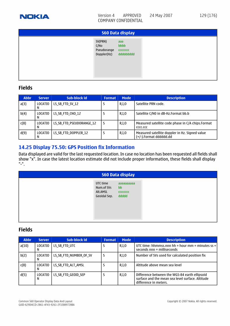
S60 Data display
aaaSV(PRN)bbbbC/NoccccccccPseudorangedddddddddDoppler(Hz)
Fields
Abbr Server Sub-block id Format Mode Description
a(3) LOCATION
LS_SB_FTD_SV_12 S R,I,O Satellite PRN code.
b(4) LOCATION
LS_SB_FTD_CNO_12 S R,I,O Satellite C/N0 in dB-Hz.Format bb.b
c(8) LOCATION
LS_SB_FTD_PSEUDORANGE_12 S R,I,O Measured satellite code phase in C/A chips.Formatcccc.ccc
d(9) LOCATION
LS_SB_FTD_DOPPLER_12 S R,I,O Measured satellite doppler in Hz. Signed value(+/-).Format dddddd.dd
14.25 Display 75.50: GPS Position fix InformationData displayed are valid for the last requested location. In case no location has been requested all fields shallshow "x". In case the latest location estimate did not include proper information, these fields shall display"-".
S60 Data display
aaaaaaaaaaUTC timebbNum.of SVsccccccccAlt.AMSLdddddGeoidal Sep.
Fields
Abbr Server Sub-block id Format Mode Description
a(10) LOCATION
LS_SB_FTD_UTC S R,I,O UTC time: hhmmss.nnn hh = hour mm = minutes ss =seconds nnn = milliseconds
b(2) LOCATION
LS_SB_FTD_NUMBER_OF_SV S R,I,O Number of SVs used for calculated position fix
c(8) LOCATION
LS_SB_FTD_ALT_AMSL S R,I,O Altitude above mean sea level
d(5) LOCATION
LS_SB_FTD_GEOID_SEP S R,I,O Difference between the WGS-84 earth ellipsoidsurface and the mean sea level surface. Altitudedifference in meters.
Version 4 APPROVED 24 May 2007COMPANY CONFIDENTIAL
129 (176)
Common S60 Operator Display Data And Layout Copyright © 2007 Nokia. All rights reserved.GUID-629D4CCD-2861-4F43-9261-2F1E889728BA

14.26 Display 75.51 GPS Satellite Information, channels 112 identical screens, one for each channel.
Used during MS Based A-GPS and Stand alone GPS positioning.
where x is the channel number 1 - 12.
The channels are reported in the order of C/N0 level. Display 75.51 has the highest C/N0 and display 75.62has the lowest C/N0. If more than 12 measurements are available, only the 12 strongest measurements willbe shown.
S60 Data display
aaaaaaaaUsed SVbbb(PRN)ccccccHealthddddC/NoeeeeeeElevationffffffAzimuth
Fields
Abbr Server Sub-block id Format Mode Description
a(8) LOCATION
LS_SB_FTD_SV_USED_1 S R,I,O Used: Satellite used for calculated positionNot used:Satellite not used for calculated position
b(3) LOCATION
LS_SB_FTD_SV_1 S R,I,O Satellite PRN code.
c(6) LOCATION
LS_SB_FTD_SV_HEALTH_1 S R,I,O OK: All NAV data are okIf not ok a 6 bit binary value isdisplayed (MSB at the left), please refer to ICD-GPS-200for details
d(4) LOCATION
LS_SB_FTD_CNO_1 S R,I,O Satellite C/N0 in dB-Hz.Format bb.b
e(6) LOCATION
LS_SB_FTD_ELEVATION_1 S R,I,O Satellite elevation.Format ccc.cc (range –90.00 to+90.00 degrees)
f(6) LOCATION
LS_SB_FTD_AZIMUTH_1 S R,I,O Satellite azimuth.Format ddd.dd (range 0 to 359.99degrees)
14.27 Display 75.52 GPS Satellite Information, channels 212 identical screens, one for each channel.
Used during MS Based A-GPS and Stand alone GPS positioning.
where x is the channel number 1 - 12.
The channels are reported in the order of C/N0 level. Display 75.51 has the highest C/N0 and display 75.62has the lowest C/N0. If more than 12 measurements are available, only the 12 strongest measurements willbe shown.
Version 4 APPROVED 24 May 2007COMPANY CONFIDENTIAL
130 (176)
Common S60 Operator Display Data And Layout Copyright © 2007 Nokia. All rights reserved.GUID-629D4CCD-2861-4F43-9261-2F1E889728BA

S60 Data display
aaaaaaaaUsed SVbbb(PRN)ccccccHealthddddC/NoeeeeeeElevationffffffAzimuth
Fields
Abbr Server Sub-block id Format Mode Description
a(8) LOCATION
LS_SB_FTD_SV_USED_2 S R,I,O Used: Satellite used for calculated positionNot used:Satellite not used for calculated position
b(3) LOCATION
LS_SB_FTD_SV_2 S R,I,O Satellite PRN code.
c(6) LOCATION
LS_SB_FTD_SV_HEALTH_2 S R,I,O OK: All NAV data are okIf not ok a 6 bit binary value isdisplayed (MSB at the left), please refer to ICD-GPS-200for details
d(4) LOCATION
LS_SB_FTD_CNO_2 S R,I,O Satellite C/N0 in dB-Hz.Format bb.b
e(6) LOCATION
LS_SB_FTD_ELEVATION_2 S R,I,O Satellite elevation.Format ccc.cc (range –90.00 to+90.00 degrees)
f(6) LOCATION
LS_SB_FTD_AZIMUTH_2 S R,I,O Satellite azimuth.Format ddd.dd (range 0 to 359.99degrees)
14.28 Display 75.53 GPS Satellite Information, channels 312 identical screens, one for each channel.
Used during MS Based A-GPS and Stand alone GPS positioning.
where x is the channel number 1 - 12.
The channels are reported in the order of C/N0 level. Display 75.51 has the highest C/N0 and display 75.62has the lowest C/N0. If more than 12 measurements are available, only the 12 strongest measurements willbe shown.
S60 Data display
aaaaaaaaUsed SVbbb(PRN)ccccccHealthddddC/NoeeeeeeElevationffffffAzimuth
Version 4 APPROVED 24 May 2007COMPANY CONFIDENTIAL
131 (176)
Common S60 Operator Display Data And Layout Copyright © 2007 Nokia. All rights reserved.GUID-629D4CCD-2861-4F43-9261-2F1E889728BA

Fields
Abbr Server Sub-block id Format Mode Description
a(8) LOCATION
LS_SB_FTD_SV_USED_3 S R,I,O Used: Satellite used for calculated positionNot used:Satellite not used for calculated position
b(3) LOCATION
LS_SB_FTD_SV_3 S R,I,O Satellite PRN code.
c(6) LOCATION
LS_SB_FTD_SV_HEALTH_3 S R,I,O OK: All NAV data are okIf not ok a 6 bit binary value isdisplayed (MSB at the left), please refer to ICD-GPS-200for details
d(4) LOCATION
LS_SB_FTD_CNO_3 S R,I,O Satellite C/N0 in dB-Hz.Format bb.b
e(6) LOCATION
LS_SB_FTD_ELEVATION_3 S R,I,O Satellite elevation.Format ccc.cc (range –90.00 to+90.00 degrees)
f(6) LOCATION
LS_SB_FTD_AZIMUTH_3 S R,I,O Satellite azimuth.Format ddd.dd (range 0 to 359.99degrees)
14.29 Display 75.54 GPS Satellite Information, channels 412 identical screens, one for each channel.
Used during MS Based A-GPS and Stand alone GPS positioning.
where x is the channel number 1 - 12.
The channels are reported in the order of C/N0 level. Display 75.51 has the highest C/N0 and display 75.62has the lowest C/N0. If more than 12 measurements are available, only the 12 strongest measurements willbe shown.
S60 Data display
aaaaaaaaUsed SVbbb(PRN)ccccccHealthddddC/NoeeeeeeElevationffffffAzimuth
Fields
Abbr Server Sub-block id Format Mode Description
a(8) LOCATION
LS_SB_FTD_SV_USED_4 S R,I,O Used: Satellite used for calculated positionNot used:Satellite not used for calculated position
b(3) LOCATION
LS_SB_FTD_SV_4 S R,I,O Satellite PRN code.
c(6) LOCATION
LS_SB_FTD_SV_HEALTH_4 S R,I,O OK: All NAV data are okIf not ok a 6 bit binary value isdisplayed (MSB at the left), please refer to ICD-GPS-200for details
d(4) LOCATION
LS_SB_FTD_CNO_4 S R,I,O Satellite C/N0 in dB-Hz.Format bb.b
e(6) LOCATION
LS_SB_FTD_ELEVATION_4 S R,I,O Satellite elevation.Format ccc.cc (range –90.00 to+90.00 degrees)
Version 4 APPROVED 24 May 2007COMPANY CONFIDENTIAL
132 (176)
Common S60 Operator Display Data And Layout Copyright © 2007 Nokia. All rights reserved.GUID-629D4CCD-2861-4F43-9261-2F1E889728BA

Abbr Server Sub-block id Format Mode Description
f(6) LOCATION
LS_SB_FTD_AZIMUTH_4 S R,I,O Satellite azimuth.Format ddd.dd (range 0 to 359.99degrees)
14.30 Display 75.55 GPS Satellite Information, channels 512 identical screens, one for each channel.
Used during MS Based A-GPS and Stand alone GPS positioning.
where x is the channel number 1 - 12.
The channels are reported in the order of C/N0 level. Display 75.51 has the highest C/N0 and display 75.62has the lowest C/N0. If more than 12 measurements are available, only the 12 strongest measurements willbe shown.
S60 Data display
aaaaaaaaUsed SVbbb(PRN)ccccccHealthddddC/NoeeeeeeElevationffffffAzimuth
Fields
Abbr Server Sub-block id Format Mode Description
a(8) LOCATION
LS_SB_FTD_SV_USED_5 S R,I,O Used: Satellite used for calculated positionNot used:Satellite not used for calculated position
b(3) LOCATION
LS_SB_FTD_SV_5 S R,I,O Satellite PRN code.
c(6) LOCATION
LS_SB_FTD_SV_HEALTH_5 S R,I,O OK: All NAV data are okIf not ok a 6 bit binary value isdisplayed (MSB at the left), please refer to ICD-GPS-200for details
d(4) LOCATION
LS_SB_FTD_CNO_5 S R,I,O Satellite C/N0 in dB-Hz.Format bb.b
e(6) LOCATION
LS_SB_FTD_ELEVATION_5 S R,I,O Satellite elevation.Format ccc.cc (range –90.00 to+90.00 degrees)
f(6) LOCATION
LS_SB_FTD_AZIMUTH_5 S R,I,O Satellite azimuth.Format ddd.dd (range 0 to 359.99degrees)
14.31 Display 75.56 GPS Satellite Information, channels 612 identical screens, one for each channel.
Used during MS Based A-GPS and Stand alone GPS positioning.
where x is the channel number 1 - 12.
The channels are reported in the order of C/N0 level. Display 75.51 has the highest C/N0 and display 75.62has the lowest C/N0. If more than 12 measurements are available, only the 12 strongest measurements willbe shown.
Version 4 APPROVED 24 May 2007COMPANY CONFIDENTIAL
133 (176)
Common S60 Operator Display Data And Layout Copyright © 2007 Nokia. All rights reserved.GUID-629D4CCD-2861-4F43-9261-2F1E889728BA

S60 Data display
aaaaaaaaUsed SVbbb(PRN)ccccccHealthddddC/NoeeeeeeElevationffffffAzimuth
Fields
Abbr Server Sub-block id Format Mode Description
a(8) LOCATION
LS_SB_FTD_SV_USED_6 S R,I,O Used: Satellite used for calculated positionNot used:Satellite not used for calculated position
b(3) LOCATION
LS_SB_FTD_SV_6 S R,I,O Satellite PRN code.
c(6) LOCATION
LS_SB_FTD_SV_HEALTH_6 S R,I,O OK: All NAV data are okIf not ok a 6 bit binary value isdisplayed (MSB at the left), please refer to ICD-GPS-200for details
d(4) LOCATION
LS_SB_FTD_CNO_6 S R,I,O Satellite C/N0 in dB-Hz.Format bb.b
e(6) LOCATION
LS_SB_FTD_ELEVATION_6 S R,I,O Satellite elevation.Format ccc.cc (range –90.00 to+90.00 degrees)
f(6) LOCATION
LS_SB_FTD_AZIMUTH_6 S R,I,O Satellite azimuth.Format ddd.dd (range 0 to 359.99degrees)
14.32 Display 75.57 GPS Satellite Information, channels 712 identical screens, one for each channel.
Used during MS Based A-GPS and Stand alone GPS positioning.
where x is the channel number 1 - 12.
The channels are reported in the order of C/N0 level. Display 75.51 has the highest C/N0 and display 75.62has the lowest C/N0. If more than 12 measurements are available, only the 12 strongest measurements willbe shown.
S60 Data display
aaaaaaaaUsed SVbbb(PRN)ccccccHealthddddC/NoeeeeeeElevationffffffAzimuth
Version 4 APPROVED 24 May 2007COMPANY CONFIDENTIAL
134 (176)
Common S60 Operator Display Data And Layout Copyright © 2007 Nokia. All rights reserved.GUID-629D4CCD-2861-4F43-9261-2F1E889728BA

Fields
Abbr Server Sub-block id Format Mode Description
a(8) LOCATION
LS_SB_FTD_SV_USED_7 S R,I,O Used: Satellite used for calculated positionNot used:Satellite not used for calculated position
b(3) LOCATION
LS_SB_FTD_SV_7 S R,I,O Satellite PRN code.
c(6) LOCATION
LS_SB_FTD_SV_HEALTH_7 S R,I,O OK: All NAV data are okIf not ok a 6 bit binary value isdisplayed (MSB at the left), please refer to ICD-GPS-200for details
d(4) LOCATION
LS_SB_FTD_CNO_7 S R,I,O Satellite C/N0 in dB-Hz.Format bb.b
e(6) LOCATION
LS_SB_FTD_ELEVATION_7 S R,I,O Satellite elevation.Format ccc.cc (range –90.00 to+90.00 degrees)
f(6) LOCATION
LS_SB_FTD_AZIMUTH_7 S R,I,O Satellite azimuth.Format ddd.dd (range 0 to 359.99degrees)
14.33 Display 75.58 GPS Satellite Information, channels 812 identical screens, one for each channel.
Used during MS Based A-GPS and Stand alone GPS positioning.
where x is the channel number 1 - 12.
The channels are reported in the order of C/N0 level. Display 75.51 has the highest C/N0 and display 75.62has the lowest C/N0. If more than 12 measurements are available, only the 12 strongest measurements willbe shown.
S60 Data display
aaaaaaaaUsed SVbbb(PRN)ccccccHealthddddC/NoeeeeeeElevationffffffAzimuth
Fields
Abbr Server Sub-block id Format Mode Description
a(8) LOCATION
LS_SB_FTD_SV_USED_8 S R,I,O Used: Satellite used for calculated positionNot used:Satellite not used for calculated position
b(3) LOCATION
LS_SB_FTD_SV_8 S R,I,O Satellite PRN code.
c(6) LOCATION
LS_SB_FTD_SV_HEALTH_8 S R,I,O OK: All NAV data are okIf not ok a 6 bit binary value isdisplayed (MSB at the left), please refer to ICD-GPS-200for details
d(4) LOCATION
LS_SB_FTD_CNO_8 S R,I,O Satellite C/N0 in dB-Hz.Format bb.b
e(6) LOCATION
LS_SB_FTD_ELEVATION_8 S R,I,O Satellite elevation.Format ccc.cc (range –90.00 to+90.00 degrees)
Version 4 APPROVED 24 May 2007COMPANY CONFIDENTIAL
135 (176)
Common S60 Operator Display Data And Layout Copyright © 2007 Nokia. All rights reserved.GUID-629D4CCD-2861-4F43-9261-2F1E889728BA

Abbr Server Sub-block id Format Mode Description
f(6) LOCATION
LS_SB_FTD_AZIMUTH_8 S R,I,O Satellite azimuth.Format ddd.dd (range 0 to 359.99degrees)
14.34 Display 75.59 GPS Satellite Information, channels 912 identical screens, one for each channel.
Used during MS Based A-GPS and Stand alone GPS positioning.
where x is the channel number 1 - 12.
The channels are reported in the order of C/N0 level. Display 75.51 has the highest C/N0 and display 75.62has the lowest C/N0. If more than 12 measurements are available, only the 12 strongest measurements willbe shown.
S60 Data display
aaaaaaaaUsed SVbbb(PRN)ccccccHealthddddC/NoeeeeeeElevationffffffAzimuth
Fields
Abbr Server Sub-block id Format Mode Description
a(8) LOCATION
LS_SB_FTD_SV_USED_9 S R,I,O Used: Satellite used for calculated positionNot used:Satellite not used for calculated position
b(3) LOCATION
LS_SB_FTD_SV_9 S R,I,O Satellite PRN code.
c(6) LOCATION
LS_SB_FTD_SV_HEALTH_9 S R,I,O OK: All NAV data are okIf not ok a 6 bit binary value isdisplayed (MSB at the left), please refer to ICD-GPS-200for details
d(4) LOCATION
LS_SB_FTD_CNO_9 S R,I,O Satellite C/N0 in dB-Hz.Format bb.b
e(6) LOCATION
LS_SB_FTD_ELEVATION_9 S R,I,O Satellite elevation.Format ccc.cc (range –90.00 to+90.00 degrees)
f(6) LOCATION
LS_SB_FTD_AZIMUTH_9 S R,I,O Satellite azimuth.Format ddd.dd (range 0 to 359.99degrees)
14.35 Display 75.60 GPS Satellite Information, channels 1012 identical screens, one for each channel.
Used during MS Based A-GPS and Stand alone GPS positioning.
where x is the channel number 1 - 12.
The channels are reported in the order of C/N0 level. Display 75.51 has the highest C/N0 and display 75.62has the lowest C/N0. If more than 12 measurements are available, only the 12 strongest measurements willbe shown.
Version 4 APPROVED 24 May 2007COMPANY CONFIDENTIAL
136 (176)
Common S60 Operator Display Data And Layout Copyright © 2007 Nokia. All rights reserved.GUID-629D4CCD-2861-4F43-9261-2F1E889728BA

S60 Data display
aaaaaaaaUsed SVbbb(PRN)ccccccHealthddddC/NoeeeeeeElevationffffffAzimuth
Fields
Abbr Server Sub-block id Format Mode Description
a(8) LOCATION
LS_SB_FTD_SV_USED_10 S R,I,O Used: Satellite used for calculated positionNot used:Satellite not used for calculated position
b(3) LOCATION
LS_SB_FTD_SV_10 S R,I,O Satellite PRN code.
c(6) LOCATION
LS_SB_FTD_SV_HEALTH_10 S R,I,O OK: All NAV data are okIf not ok a 6 bit binary value isdisplayed (MSB at the left), please refer to ICD-GPS-200for details
d(4) LOCATION
LS_SB_FTD_CNO_10 S R,I,O Satellite C/N0 in dB-Hz.Format bb.b
e(6) LOCATION
LS_SB_FTD_ELEVATION_10 S R,I,O Satellite elevation.Format ccc.cc (range –90.00 to+90.00 degrees)
f(6) LOCATION
LS_SB_FTD_AZIMUTH_10 S R,I,O Satellite azimuth.Format ddd.dd (range 0 to 359.99degrees)
14.36 Display 75.61 GPS Satellite Information, channels 1112 identical screens, one for each channel.
Used during MS Based A-GPS and Stand alone GPS positioning.
where x is the channel number 1 - 12.
The channels are reported in the order of C/N0 level. Display 75.51 has the highest C/N0 and display 75.62has the lowest C/N0.If more than 12 measurements are available, only the 12 strongest measurements willbe shown.
S60 Data display
aaaaaaaaUsed SVbbb(PRN)ccccccHealthddddC/NoeeeeeeElevationffffffAzimuth
Version 4 APPROVED 24 May 2007COMPANY CONFIDENTIAL
137 (176)
Common S60 Operator Display Data And Layout Copyright © 2007 Nokia. All rights reserved.GUID-629D4CCD-2861-4F43-9261-2F1E889728BA

Fields
Abbr Server Sub-block id Format Mode Description
a(8) LOCATION
LS_SB_FTD_SV_USED_11 S R,I,O Used: Satellite used for calculated positionNot used:Satellite not used for calculated position
b(3) LOCATION
LS_SB_FTD_SV_11 S R,I,O Satellite PRN code.
c(6) LOCATION
LS_SB_FTD_SV_HEALTH_11 S R,I,O OK: All NAV data are okIf not ok a 6 bit binary value isdisplayed (MSB at the left), please refer to ICD-GPS-200for details
d(4) LOCATION
LS_SB_FTD_CNO_11 S R,I,O Satellite C/N0 in dB-Hz.Format bb.b
e(6) LOCATION
LS_SB_FTD_ELEVATION_11 S R,I,O Satellite elevation.Format ccc.cc (range –90.00 to+90.00 degrees)
f(6) LOCATION
LS_SB_FTD_AZIMUTH_11 S R,I,O Satellite azimuth.Format ddd.dd (range 0 to 359.99degrees)
14.37 Display 75.62 GPS Satellite Information, channels 1212 identical screens, one for each channel.
Used during MS Based A-GPS and Stand alone GPS positioning.
where x is the channel number 1 - 12.
The channels are reported in the order of C/N0 level. Display 75.51 has the highest C/N0 and display 75.62has the lowest C/N0. If more than 12 measurements are available, only the 12 strongest measurements willbe shown.
S60 Data display
aaaaaaaaUsed SVbbb(PRN)ccccccHealthddddC/NoeeeeeeElevationffffffAzimuth
Fields
Abbr Server Sub-block id Format Mode Description
a(8) LOCATION
LS_SB_FTD_SV_USED_12 S R,I,O Used: Satellite used for calculated positionNot used:Satellite not used for calculated position
b(3) LOCATION
LS_SB_FTD_SV_12 S R,I,O Satellite PRN code.
c(6) LOCATION
LS_SB_FTD_SV_HEALTH_12 S R,I,O OK: All NAV data are okIf not ok a 6 bit binary value isdisplayed (MSB at the left), please refer to ICD-GPS-200for details
d(4) LOCATION
LS_SB_FTD_CNO_12 S R,I,O Satellite C/N0 in dB-Hz.Format bb.b
e(6) LOCATION
LS_SB_FTD_ELEVATION_12 S R,I,O Satellite elevation.Format ccc.cc (range –90.00 to+90.00 degrees)
Version 4 APPROVED 24 May 2007COMPANY CONFIDENTIAL
138 (176)
Common S60 Operator Display Data And Layout Copyright © 2007 Nokia. All rights reserved.GUID-629D4CCD-2861-4F43-9261-2F1E889728BA

Abbr Server Sub-block id Format Mode Description
f(6) LOCATION
LS_SB_FTD_AZIMUTH_12 S R,I,O Satellite azimuth.Format ddd.dd (range 0 to 359.99degrees)
14.38 Display 75.68: GPS Assistance data from networkThis display shows which GPS assistance data has been received from the network.
When Location Server starts a new Location procedure, all fields in this display will be cleared. Whenassistance data are received from network the appropriate fields will be updated. "xx" = unavailable, "11" =available. Furthermore actual values for reference time accuracy (microsec) and Reference location accuracy(m) are displayed.
S60 Data display
aaIO UT bbAL AA ccRT DG
dd
EP TAee
r.tim.acc
ff
LA
gg
r.loc.acc
hhiiiiiiiiijjkkkkkkkkk
Fields
Abbr Server Sub-block id Format Mode Description
a(2) LOCATION
LS_SB_FTD_ASS_IONO S R,I,O Ionospheric
b(2) LOCATION
LS_SB_FTD_ASS_UTC S R,I,O UTC
c(2) LOCATION
LS_SB_FTD_ASS_ALMANAC S R,I,O Almanac
d(2) LOCATION
LS_SB_FTD_ASS_AA S R,I,O Aqcusition assistance
e(2) LOCATION
LS_SB_FTD_ASS_RTI S R,I,O RTI
f(2) LOCATION
LS_SB_FTD_ASS_DGPS S R,I,O DGPS corrections
g(2) LOCATION
LS_SB_FTD_ASS_EPHEMERIS S R,I,O Ephemeris
h(2) LOCATION
LS_SB_FTD_ASS_REF_TIME_AVAIL S R,I,O Ref time availability
i(9) LOCATION
LS_SB_FTD_ASS_REF_TIME_ACC S R,I,O Ref.time accuracy in microsecs
j(2) LOCATION
LS_SB_FTD_ASS_REF_LOC_AVAIL S R,I,O Ref.loc availability
k(9) LOCATION
LS_SB_FTD_ASS_REF_LOC_ACC S R,I,O Ref.loc. accuracy in meters.
14.39 Display 75.69: GPS User DOP InformationDOPs displayed are valid for the last requested location.
If the DOPs were not requested from the latest location request, the specific fields shall display "x". If theDOPs were requested but not available the fields shall show "-".
Version 4 APPROVED 24 May 2007COMPANY CONFIDENTIAL
139 (176)
Common S60 Operator Display Data And Layout Copyright © 2007 Nokia. All rights reserved.GUID-629D4CCD-2861-4F43-9261-2F1E889728BA
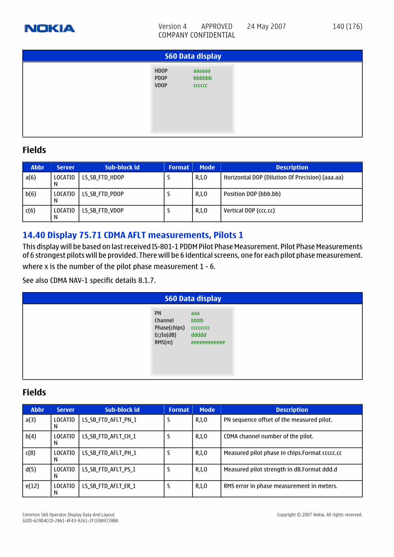
S60 Data display
aaaaaaHDOPbbbbbbPDOPccccccVDOP
Fields
Abbr Server Sub-block id Format Mode Description
a(6) LOCATION
LS_SB_FTD_HDOP S R,I,O Horizontal DOP (Dilution Of Precision) (aaa.aa)
b(6) LOCATION
LS_SB_FTD_PDOP S R,I,O Position DOP (bbb.bb)
c(6) LOCATION
LS_SB_FTD_VDOP S R,I,O Vertical DOP (ccc.cc)
14.40 Display 75.71 CDMA AFLT measurements, Pilots 1This display will be based on last received IS-801-1 PDDM Pilot Phase Measurement. Pilot Phase Measurementsof 6 strongest pilots will be provided. There will be 6 identical screens, one for each pilot phase measurement.
where x is the number of the pilot phase measurement 1 - 6.
See also CDMA NAV-1 specific details 8.1.7.
S60 Data display
aaaPNbbbbChannelccccccccPhase(chips)dddddEc/Io(dB)eeeeeeeeeeeeRMS(m)
Fields
Abbr Server Sub-block id Format Mode Description
a(3) LOCATION
LS_SB_FTD_AFLT_PN_1 S R,I,O PN sequence offset of the measured pilot.
b(4) LOCATION
LS_SB_FTD_AFLT_CH_1 S R,I,O CDMA channel number of the pilot.
c(8) LOCATION
LS_SB_FTD_AFLT_PH_1 S R,I,O Measured pilot phase in chips.Format ccccc.cc
d(5) LOCATION
LS_SB_FTD_AFLT_PS_1 S R,I,O Measured pilot strength in dB.Format ddd.d
e(12) LOCATION
LS_SB_FTD_AFLT_ER_1 S R,I,O RMS error in phase measurement in meters.
Version 4 APPROVED 24 May 2007COMPANY CONFIDENTIAL
140 (176)
Common S60 Operator Display Data And Layout Copyright © 2007 Nokia. All rights reserved.GUID-629D4CCD-2861-4F43-9261-2F1E889728BA

14.41 Display 75.72 CDMA AFLT measurements, Pilots 2This display will be based on last received IS-801-1 PDDM Pilot Phase Measurement. Pilot Phase Measurementsof 6 strongest pilots will be provided. There will be 6 identical screens, one for each pilot phase measurement.
where x is the number of the pilot phase measurement 1 - 6.
See also CDMA NAV-1 specific details 8.1.7.
S60 Data display
aaaPNbbbbChannelccccccccPhase(chips)dddddEc/Io(dB)eeeeeeeeeeeeRMS(m)
Fields
Abbr Server Sub-block id Format Mode Description
a(3) LOCATION
LS_SB_FTD_AFLT_PN_2 S R,I,O PN sequence offset of the measured pilot.
b(4) LOCATION
LS_SB_FTD_AFLT_CH_2 S R,I,O CDMA channel number of the pilot.
c(8) LOCATION
LS_SB_FTD_AFLT_PH_2 S R,I,O Measured pilot phase in chips.Format ccccc.cc
d(5) LOCATION
LS_SB_FTD_AFLT_PS_2 S R,I,O Measured pilot strength in dB.Format ddd.d
e(12) LOCATION
LS_SB_FTD_AFLT_ER_2 S R,I,O RMS error in phase measurement in meters.
14.42 Display 75.73 CDMA AFLT measurements, Pilots 3This display will be based on last received IS-801-1 PDDM Pilot Phase Measurement. Pilot Phase Measurementsof 6 strongest pilots will be provided. There will be 6 identical screens, one for each pilot phase measurement.
where x is the number of the pilot phase measurement 1 - 6.
See also CDMA NAV-1 specific details 8.1.7.
S60 Data display
aaaPNbbbbChannelccccccccPhase(chips)dddddEc/Io(dB)eeeeeeeeeeeeRMS(m)
Version 4 APPROVED 24 May 2007COMPANY CONFIDENTIAL
141 (176)
Common S60 Operator Display Data And Layout Copyright © 2007 Nokia. All rights reserved.GUID-629D4CCD-2861-4F43-9261-2F1E889728BA

Fields
Abbr Server Sub-block id Format Mode Description
a(3) LOCATION
LS_SB_FTD_AFLT_PN_3 S R,I,O PN sequence offset of the measured pilot.
b(4) LOCATION
LS_SB_FTD_AFLT_CH_3 S R,I,O CDMA channel number of the pilot.
c(8) LOCATION
LS_SB_FTD_AFLT_PH_3 S R,I,O Measured pilot phase in chips.Format ccccc.cc
d(5) LOCATION
LS_SB_FTD_AFLT_PS_3 S R,I,O Measured pilot strength in dB.Format ddd.d
e(12) LOCATION
LS_SB_FTD_AFLT_ER_3 S R,I,O RMS error in phase measurement in meters.
14.43 Display 75.74 CDMA AFLT measurements, Pilots 4This display will be based on last received IS-801-1 PDDM Pilot Phase Measurement. Pilot Phase Measurementsof 6 strongest pilots will be provided. There will be 6 identical screens, one for each pilot phase measurement.
where x is the number of the pilot phase measurement 1 - 6.
See also CDMA NAV-1 specific details 8.1.7.
S60 Data display
aaaPNbbbbChannelccccccccPhase(chips)dddddEc/Io(dB)eeeeeeeeeeeeRMS(m)
Fields
Abbr Server Sub-block id Format Mode Description
a(3) LOCATION
LS_SB_FTD_AFLT_PN_4 S R,I,O PN sequence offset of the measured pilot.
b(4) LOCATION
LS_SB_FTD_AFLT_CH_4 S R,I,O CDMA channel number of the pilot.
c(8) LOCATION
LS_SB_FTD_AFLT_PH_4 S R,I,O Measured pilot phase in chips.Format ccccc.cc
d(5) LOCATION
LS_SB_FTD_AFLT_PS_4 S R,I,O Measured pilot strength in dB.Format ddd.d
e(12) LOCATION
LS_SB_FTD_AFLT_ER_4 S R,I,O RMS error in phase measurement in meters.
14.44 Display 75.75 CDMA AFLT measurements, Pilots 5This display will be based on last received IS-801-1 PDDM Pilot Phase Measurement. Pilot Phase Measurementsof 6 strongest pilots will be provided. There will be 6 identical screens, one for each pilot phase measurement.
where x is the number of the pilot phase measurement 1 - 6.
See also CDMA NAV-1 specific details 8.1.7.
Version 4 APPROVED 24 May 2007COMPANY CONFIDENTIAL
142 (176)
Common S60 Operator Display Data And Layout Copyright © 2007 Nokia. All rights reserved.GUID-629D4CCD-2861-4F43-9261-2F1E889728BA

S60 Data display
aaaPNbbbbChannelccccccccPhase(chips)dddddEc/Io(dB)eeeeeeeeeeeeRMS(m)
Fields
Abbr Server Sub-block id Format Mode Description
a(3) LOCATION
LS_SB_FTD_AFLT_PN_5 S R,I,O PN sequence offset of the measured pilot.
b(4) LOCATION
LS_SB_FTD_AFLT_CH_5 S R,I,O CDMA channel number of the pilot.
c(8) LOCATION
LS_SB_FTD_AFLT_PH_5 S R,I,O Measured pilot phase in chips.Format ccccc.cc
d(5) LOCATION
LS_SB_FTD_AFLT_PS_5 S R,I,O Measured pilot strength in dB.Format ddd.d
e(12) LOCATION
LS_SB_FTD_AFLT_ER_5 S R,I,O RMS error in phase measurement in meters.
14.45 Display 75.76 CDMA AFLT measurements, Pilots 6This display will be based on last received IS-801-1 PDDM Pilot Phase Measurement. Pilot Phase Measurementsof 6 strongest pilots will be provided. There will be 6 identical screens, one for each pilot phase measurement.
where x is the number of the pilot phase measurement 1 - 6.
See also CDMA NAV-1 specific details 8.1.7.
S60 Data display
aaaPNbbbbChannelccccccccPhase(chips)dddddEc/Io(dB)eeeeeeeeeeeeRMS(m)
Fields
Abbr Server Sub-block id Format Mode Description
a(3) LOCATION
LS_SB_FTD_AFLT_PN_6 S R,I,O PN sequence offset of the measured pilot.
b(4) LOCATION
LS_SB_FTD_AFLT_CH_6 S R,I,O CDMA channel number of the pilot.
c(8) LOCATION
LS_SB_FTD_AFLT_PH_6 S R,I,O Measured pilot phase in chips.Format ccccc.cc
Version 4 APPROVED 24 May 2007COMPANY CONFIDENTIAL
143 (176)
Common S60 Operator Display Data And Layout Copyright © 2007 Nokia. All rights reserved.GUID-629D4CCD-2861-4F43-9261-2F1E889728BA

Abbr Server Sub-block id Format Mode Description
d(5) LOCATION
LS_SB_FTD_AFLT_PS_6 S R,I,O Measured pilot strength in dB.Format ddd.d
e(12) LOCATION
LS_SB_FTD_AFLT_ER_6 S R,I,O RMS error in phase measurement in meters.
14.46 Display 75.77: Pseudorange and Pilot Phase Measurement RequestsThis display will be based on last received IS-801-1 PDDM Request Pilot Phase Measurement and RequestPseudorange Measurement.
S60 Data display
aaaAFLT PRQ(s)bbbNUM_FIXcccTBFdddGPS PRQ(s)eeeNUM_FIXfffTBF
Fields
Abbr Server Sub-block id Format Mode Description
a(3) LOCATION
LS_SB_FTD_AFLT_PRQ S R,I,O Preferred Response Quality from the last Request PilotPhase Measurement PDDM.
b(3) LOCATION
LS_SB_FTD_AFLT_NUM_FIXES S R,I,O Number of Fixes from the last Request Pilot PhaseMeasurement PDDM.
c(3) LOCATION
LS_SB_FTD_AFLT_TBF S R,I,O Time Between Fixes from the last Request Pilot PhaseMeasurement PDDM.
d(3) LOCATION
LS_SB_FTD_GPS_PRQ S R,I,O Preferred Response Quality from the last RequestPseudorange Measurement PDDM.
e(3) LOCATION
LS_SB_FTD_GPS_NUM_FIXES S R,I,O Number of Fixes from the last Request PseudorangeMeasurement PDDM.
f(3) LOCATION
LS_SB_FTD_GPS_TBF S R,I,O Time Between Fixes from the last RequestPseudorange Measurement PDDM.
14.47 Display 75.78: Pilot Phase and Pseudorange measurement countThis display will be based on
-last received IS-801-1 PDDM Pilot Phase Measurement
-last received IS-801-1 PDDM Pseudorange Measurement
See also CDMA NAV-1 specific details 8.1.9.
Version 4 APPROVED 24 May 2007COMPANY CONFIDENTIAL
144 (176)
Common S60 Operator Display Data And Layout Copyright © 2007 Nokia. All rights reserved.GUID-629D4CCD-2861-4F43-9261-2F1E889728BA

S60 Data display
aaaPPhase countbbbbbMeas.Time(s)cccPRange countdddddMeas.Time(s)
Fields
Abbr Server Sub-block id Format Mode Description
a(3) LOCATION
LS_SB_FTD_AFLT_PILOT_COUNT S R,I,O Number of Pilot Phase measurement sent in lastProvide Pilot Phase Measurement PDDM.
b(5) LOCATION
LS_ SB_FTD_AFLT_PILOT_RESP_TIME
S R,I,O Time it took to make measurements for this particularPilot Phase Measurement Request in seconds,resolution 0.1 sec. Format bbb.b
c(3) LOCATION
LS_ SB_FTD_PSEUDORANGE_COUNT
S R,I,O Number of Pseudorange measurement sent in lastProvide Pseudorange Measurement PDDM
d(5) LOCATION
LS_SB_FTD_TIME_BASE S R,I,O Time it took to make measurements for this particularPseudorange Measurement Request in seconds,resolution 0.1 sec. Format ddd.d
14.48 Display 75.80: E-OTD Measurement InfoThis display will be based on last sent LS_GSM_ LOCATE_RESP and itsLS_SB_GSM_EOTD_MEAS_INFO andLS_GSM_EOTD_MEASD_SETS_SEQ elements
NOTE!
All numerical values are shown in decimal.
This display contains E-OTD measurement information in the Measure Position Response component in RRLPthat is sent from MS to the network.
If no GSM_LS_LOCATE_RESP with LS_SB_GSM_EOTD_MEAS_INFO has been sent, the display shall show "x" in alldata fields.
S60 Data display
aNr of SetsbbbbbRef. FNcccTA Corr.ddNr of Neighs
Fields
Abbr Server Sub-block id Format Mode Description
a LOCATION
LS_ SB_FTD_GSM_MEAS_SET_COUNT
S R,I,O Number of Measurement Sets: This field indicates thenumber of E-OTD measurement sets.
Version 4 APPROVED 24 May 2007COMPANY CONFIDENTIAL
145 (176)
Common S60 Operator Display Data And Layout Copyright © 2007 Nokia. All rights reserved.GUID-629D4CCD-2861-4F43-9261-2F1E889728BA

Abbr Server Sub-block id Format Mode Description
b(5) LOCATION
LS_SB_FTD_GSM_REF_FN S R,I,O Reference Frame Number: This field indicates theframe number of the last measured burst from thereference BTS modulo 42432.
c(3) LOCATION
LS_SB_FTD_GSM_TA_CORR S R,I,O TA Correction: This field indicates the measured TAcorrection value.
d(2) LOCATION
LS_SB_FTD_GSM_MEASD_NEIGH S R,I,O Number Of Neighbors: This field indicates the numberof measured neighbors.
14.49 Display 75.81: E-OTD Reference BTS, Reference BTS set 1This display will be based on last sent LS_GSM_ LOCATE_RESP with LS_SB_GSM_EOTD_REF_BTS_ID
NOTE!
All numerical values are shown in decimal.
These displays indentifies the reference BTS of the first measurement set in the Measure Position Responsecomponent in RRLP that is sent from MS to the network.
The content of the display varies depending on the CellIDType.
If no LS_GSM_ LOCATE_RESP with LS_SB_GSM_EOTD_REF_BTS_ID has not been sent, the display shall show "x" inall data fields.
If Cell ID Type is not in range 0..4 then the displays shall show "?" in all data fields.
S60 Data display
aCell Type:bbbbbbbbbbbbccccccccccccdddddddddddd
Fields
Abbr Server Sub-block id Format Mode Description
a LOCATION
LS_SB_FTD_GSM_CELLID_TYP S R,I,O CellIDType: Indicates the identity method of theReference BTS
b(12) LOCATION
LS_SB_FTD_GSM_REF_LAC S R,I,O Cell ID type: (text + value) 0: empty (no text, no value)1: empty (no text, no value) 2: empty (no text, novalue) 3: empty (no text, no value) 4: Area: xxxxx xxxxxis Reference LAC: Indicates the Location Area Code ofthe reference BTS.
c(12) LOCATION
LS_SB_FTD_GSM_REF_BTS_1 S R,I,O Cell ID type: (text + value) 0: BS ID: yy yy is ReferenceBSIC: Indicates the Base Station Indentity. 1: Cell ID: 2:ReqIndex: zz zz is Request Index: Indicates an indexidentifying the reference BTSs by referring to the BTSslisted in the Measure Position Request component. 3:System Info 4: Cell ID:
d(12) LOCATION
LS_SB_FTD_GSM_REF_BTS_2 S R,I,O Cell ID type: (text + value) 0: BCCH: uuuu uuuu isReference BCCH carrier: This field indicates theabsolute RF channel number of the BCCH of thereference base station. 1: vvvvvvvvvv vvvvvvvvvv isReference CI: Indicates the Cell Identity value of thereference BTS. 2: empty (no text, no value) 3: Index:www www is System Info Index: Indicates an index
Version 4 APPROVED 24 May 2007COMPANY CONFIDENTIAL
146 (176)
Common S60 Operator Display Data And Layout Copyright © 2007 Nokia. All rights reserved.GUID-629D4CCD-2861-4F43-9261-2F1E889728BA

Abbr Server Sub-block id Format Mode Descriptionidentifying the reference BTS by referring to BCCHallocation list of the serving BTS. 4: vvvvvvvvvvvvvvvvvvvv is Reference CI: Indicates the Cell Identityvalue of the reference BTS.
14.50 Display 75.82 E-OTD Measurement Info, Measurement Set 1, Neighbours 1The 15 displays in range 75.82..75.96 are all identical. However, each display will concern only one specificneighbour base station. The mapping between display and neighbour base station is shown below:
Display
75.82
75.83
75.84
75.85
75.86
75.87
75.88
75.89
75.90
75.91
75.92
75.93
75.94
75.95
75.96
Neighbour
1 2 3 4 5 6 7 8 9 10 11 12 13 14 15
This display will be based on last sent LS_GSM_ LOCATE_RESP and its LS_SB_GSM_EOTD_MEAS_INFO,LS_GSM_EOTD_MEASD_SETS_SEQ and LS_GSM_EOTD_MEASD_NB_SEQ elements
The display for neighbour 1 is shown below:
NOTE!
1. The "1" character shown in first column of the "Data Display" is the neighbour id. It will have range 1..9,A..F, - depending on the display.
2. The "1" character shown in first column of the "Help Display" is the neighbour id. It will have range 1..15,- depending on the display
3. The Sub Block IDs written above will have similar names for each of the 15 neighbours, - however theending "_1" is exchanged with the corresponding neighbour number (1..15).
S60 Data display
aaaaaaaaaa1. Neigh IDbbbbbbbNbr of Meas.ccccccccStd of Meas.dddddOTD value
Fields
Abbr Server Sub-block id Format Mode Description
a(10) LOCATION
LS_SB_FTD_GSM_NEIGH_ID_1 S R,I,O Neighbor BCCH carrier or cell identity: This fieldindicates the absolute RF channel number of the BCCH(Cell ID Type 0 and 2) or the Cell Identity value (Cell IDType 1 and 5) of the neighbor base station.
b(7) LOCATION
LS_ SB_FTD_GSM_EOTD_MEAS_COUNT_1
S R,I,O Number of E-OTD Measurements (shown as aninterval, e.g. 00 04). If the Number of EOTDMeasurements field has a bit value 111 , this field willshow 55 xx to indicate situation 55 or more EOTDmeasurements
Version 4 APPROVED 24 May 2007COMPANY CONFIDENTIAL
147 (176)
Common S60 Operator Display Data And Layout Copyright © 2007 Nokia. All rights reserved.GUID-629D4CCD-2861-4F43-9261-2F1E889728BA

Abbr Server Sub-block id Format Mode Description
c(8) LOCATION
LS_ SB_FTD_GSM_STD_EOTD_MEAS_1
S R,I,O Std of EOTD Measurements (shown as an interval, e.g.000..009). Defines standard deviation of EOTDmeasurements in meters. Calculated according to GSM04.31 using STD resolution field inLS_GSM_EOTD_MEASD_SETS_SEQ and STD of EOTDmeasurement field in LS_GSM_EOTD_MEASD_NB_SEQ. Ifthe Std of EOTD Measurements field has a bit value11111 , this field will show ccc..xxx to indicatesituation ccc meters or more , e.g. "620..xxx".
d(5) LOCATION
LS_SB_FTD_GSM_MEASD_OTD_1 S R,I,O OTD: Indicates the measured OTD value between thereceptions of signals from the reference and theneighbor BTS.
14.51 Display 75.83 E-OTD Measurement Info, Measurement Set 1, Neighbours 2The 15 displays in range 75.82..75.96 are all identical. However, each display will concern only one specificneighbour base station. The mapping between display and neighbour base station is shown below:
Display
75.82
75.83
75.84
75.85
75.86
75.87
75.88
75.89
75.90
75.91
75.92
75.93
75.94
75.95
75.96
Neighbour
1 2 3 4 5 6 7 8 9 10 11 12 13 14 15
This display will be based on last sent LS_GSM_ LOCATE_RESP and its LS_SB_GSM_EOTD_MEAS_INFO,LS_GSM_EOTD_MEASD_SETS_SEQ and LS_GSM_EOTD_MEASD_NB_SEQ elements
The display for neighbour 1 is shown below:
NOTE!
1. The "1" character shown in first column of the "Data Display" is the neighbour id. It will have range 1..9,A..F, - depending on the display.
2. The "1" character shown in first column of the "Help Display" is the neighbour id. It will have range 1..15,- depending on the display
3. The Sub Block IDs written above will have similar names for each of the 15 neighbours, - however theending "_1" is exchanged with the corresponding neighbour number (1..15).
S60 Data display
aaaaaaaaaa2. Neigh IDbbbbbbbNbr of Meas.ccccccccStd of Meas.dddddOTD value
Version 4 APPROVED 24 May 2007COMPANY CONFIDENTIAL
148 (176)
Common S60 Operator Display Data And Layout Copyright © 2007 Nokia. All rights reserved.GUID-629D4CCD-2861-4F43-9261-2F1E889728BA

Fields
Abbr Server Sub-block id Format Mode Description
a(10) LOCATION
LS_SB_FTD_GSM_NEIGH_ID_2 S R,I,O Neighbor BCCH carrier or cell identity: This fieldindicates the absolute RF channel number of the BCCH(Cell ID Type 0 and 2) or the Cell Identity value (Cell IDType 1 and 5) of the neighbor base station.
b(7) LOCATION
LS_ SB_FTD_GSM_EOTD_MEAS_COUNT_2
S R,I,O Number of E-OTD Measurements (shown as aninterval, e.g. 00 04). If the Number of EOTDMeasurements field has a bit value 111 , this field willshow 55 xx to indicate situation 55 or more EOTDmeasurements
c(8) LOCATION
LS_ SB_FTD_GSM_STD_EOTD_MEAS_2
S R,I,O Std of EOTD Measurements (shown as an interval, e.g.000..009). Defines standard deviation of EOTDmeasurements in meters. Calculated according to GSM04.31 using STD resolution field inLS_GSM_EOTD_MEASD_SETS_SEQ and STD of EOTDmeasurement field in LS_GSM_EOTD_MEASD_NB_SEQ. Ifthe Std of EOTD Measurements field has a bit value11111 , this field will show ccc..xxx to indicatesituation ccc meters or more , e.g. "620..xxx".
d(5) LOCATION
LS_SB_FTD_GSM_MEASD_OTD_2 S R,I,O OTD: Indicates the measured OTD value between thereceptions of signals from the reference and theneighbor BTS.
14.52 Display 75.84 E-OTD Measurement Info, Measurement Set 1, Neighbours 3The 15 displays in range 75.82..75.96 are all identical. However, each display will concern only one specificneighbour base station. The mapping between display and neighbour base station is shown below:
Display
75.82
75.83
75.84
75.85
75.86
75.87
75.88
75.89
75.90
75.91
75.92
75.93
75.94
75.95
75.96
Neighbour
1 2 3 4 5 6 7 8 9 10 11 12 13 14 15
This display will be based on last sent LS_GSM_ LOCATE_RESP and its LS_SB_GSM_EOTD_MEAS_INFO,LS_GSM_EOTD_MEASD_SETS_SEQ and LS_GSM_EOTD_MEASD_NB_SEQ elements
The display for neighbour 1 is shown below:
NOTE!
1. The "1" character shown in first column of the "Data Display" is the neighbour id. It will have range 1..9,A..F, - depending on the display.
2. The "1" character shown in first column of the "Help Display" is the neighbour id. It will have range 1..15,- depending on the display
3. The Sub Block IDs written above will have similar names for each of the 15 neighbours, - however theending "_1" is exchanged with the corresponding neighbour number (1..15).
Version 4 APPROVED 24 May 2007COMPANY CONFIDENTIAL
149 (176)
Common S60 Operator Display Data And Layout Copyright © 2007 Nokia. All rights reserved.GUID-629D4CCD-2861-4F43-9261-2F1E889728BA

S60 Data display
aaaaaaaaaa3. Neigh IDbbbbbbbNbr of Meas.ccccccccStd of Meas.dddddOTD value
Fields
Abbr Server Sub-block id Format Mode Description
a(10) LOCATION
LS_SB_FTD_GSM_NEIGH_ID_3 S R,I,O Neighbor BCCH carrier or cell identity: This fieldindicates the absolute RF channel number of the BCCH(Cell ID Type 0 and 2) or the Cell Identity value (Cell IDType 1 and 5) of the neighbor base station.
b(7) LOCATION
LS_ SB_FTD_GSM_EOTD_MEAS_COUNT_3
S R,I,O Number of E-OTD Measurements (shown as aninterval, e.g. 00 04). If the Number of EOTDMeasurements field has a bit value 111 , this field willshow 55 xx to indicate situation 55 or more EOTDmeasurements
c(8) LOCATION
LS_ SB_FTD_GSM_STD_EOTD_MEAS_3
S R,I,O Std of EOTD Measurements (shown as an interval, e.g.000..009). Defines standard deviation of EOTDmeasurements in meters. Calculated according to GSM04.31 using STD resolution field inLS_GSM_EOTD_MEASD_SETS_SEQ and STD of EOTDmeasurement field in LS_GSM_EOTD_MEASD_NB_SEQ. Ifthe Std of EOTD Measurements field has a bit value11111 , this field will show ccc..xxx to indicatesituation ccc meters or more , e.g. "620..xxx".
d(5) LOCATION
LS_SB_FTD_GSM_MEASD_OTD_3 S R,I,O OTD: Indicates the measured OTD value between thereceptions of signals from the reference and theneighbor BTS.
14.53 Display 75.85 E-OTD Measurement Info, Measurement Set 1, Neighbours 4The 15 displays in range 75.82..75.96 are all identical. However, each display will concern only one specificneighbour base station. The mapping between display and neighbour base station is shown below:
Display
75.82
75.83
75.84
75.85
75.86
75.87
75.88
75.89
75.90
75.91
75.92
75.93
75.94
75.95
75.96
Neighbour
1 2 3 4 5 6 7 8 9 10 11 12 13 14 15
This display will be based on last sent LS_GSM_ LOCATE_RESP and its LS_SB_GSM_EOTD_MEAS_INFO,LS_GSM_EOTD_MEASD_SETS_SEQ and LS_GSM_EOTD_MEASD_NB_SEQ elements
The display for neighbour 1 is shown below:
NOTE!
1. The "1" character shown in first column of the "Data Display" is the neighbour id. It will have range 1..9,A..F, - depending on the display.
Version 4 APPROVED 24 May 2007COMPANY CONFIDENTIAL
150 (176)
Common S60 Operator Display Data And Layout Copyright © 2007 Nokia. All rights reserved.GUID-629D4CCD-2861-4F43-9261-2F1E889728BA

2. The "1" character shown in first column of the "Help Display" is the neighbour id. It will have range 1..15,- depending on the display
3. The Sub Block IDs written above will have similar names for each of the 15 neighbours, - however theending "_1" is exchanged with the corresponding neighbour number (1..15).
S60 Data display
aaaaaaaaaa4. Neigh IDbbbbbbbNbr of Meas.ccccccccStd of Meas.dddddOTD value
Fields
Abbr Server Sub-block id Format Mode Description
a(10) LOCATION
LS_SB_FTD_GSM_NEIGH_ID_4 S R,I,O Neighbor BCCH carrier or cell identity: This fieldindicates the absolute RF channel number of the BCCH(Cell ID Type 0 and 2) or the Cell Identity value (Cell IDType 1 and 5) of the neighbor base station.
b(7) LOCATION
LS_ SB_FTD_GSM_EOTD_MEAS_COUNT_4
S R,I,O Number of E-OTD Measurements (shown as aninterval, e.g. 00 04). If the Number of EOTDMeasurements field has a bit value 111 , this field willshow 55 xx to indicate situation 55 or more EOTDmeasurements
c(8) LOCATION
LS_ SB_FTD_GSM_STD_EOTD_MEAS_4
S R,I,O Std of EOTD Measurements (shown as an interval, e.g.000..009). Defines standard deviation of EOTDmeasurements in meters. Calculated according to GSM04.31 using STD resolution field inLS_GSM_EOTD_MEASD_SETS_SEQ and STD of EOTDmeasurement field in LS_GSM_EOTD_MEASD_NB_SEQ. Ifthe Std of EOTD Measurements field has a bit value11111 , this field will show ccc..xxx to indicatesituation ccc meters or more , e.g. "620..xxx".
d(5) LOCATION
LS_SB_FTD_GSM_MEASD_OTD_4 S R,I,O OTD: Indicates the measured OTD value between thereceptions of signals from the reference and theneighbor BTS.
14.54 Display 75.86 E-OTD Measurement Info, Measurement Set 1, Neighbours 5The 15 displays in range 75.82..75.96 are all identical. However, each display will concern only one specificneighbour base station. The mapping between display and neighbour base station is shown below:
Display
75.82
75.83
75.84
75.85
75.86
75.87
75.88
75.89
75.90
75.91
75.92
75.93
75.94
75.95
75.96
Neighbour
1 2 3 4 5 6 7 8 9 10 11 12 13 14 15
This display will be based on last sent LS_GSM_ LOCATE_RESP and its LS_SB_GSM_EOTD_MEAS_INFO,LS_GSM_EOTD_MEASD_SETS_SEQ and LS_GSM_EOTD_MEASD_NB_SEQ elements
The display for neighbour 1 is shown below:
Version 4 APPROVED 24 May 2007COMPANY CONFIDENTIAL
151 (176)
Common S60 Operator Display Data And Layout Copyright © 2007 Nokia. All rights reserved.GUID-629D4CCD-2861-4F43-9261-2F1E889728BA

NOTE!
1. The "1" character shown in first column of the "Data Display" is the neighbour id. It will have range 1..9,A..F, - depending on the display.
2. The "1" character shown in first column of the "Help Display" is the neighbour id. It will have range 1..15,- depending on the display
3. The Sub Block IDs written above will have similar names for each of the 15 neighbours, - however theending "_1" is exchanged with the corresponding neighbour number (1..15).
S60 Data display
aaaaaaaaaa5. Neigh IDbbbbbbbNbr of Meas.ccccccccStd of Meas.dddddOTD value
Fields
Abbr Server Sub-block id Format Mode Description
a(10) LOCATION
LS_SB_FTD_GSM_NEIGH_ID_5 S R,I,O Neighbor BCCH carrier or cell identity: This fieldindicates the absolute RF channel number of the BCCH(Cell ID Type 0 and 2) or the Cell Identity value (Cell IDType 1 and 5) of the neighbor base station.
b(7) LOCATION
LS_ SB_FTD_GSM_EOTD_MEAS_COUNT_5
S R,I,O Number of E-OTD Measurements (shown as aninterval, e.g. 00 04). If the Number of EOTDMeasurements field has a bit value 111 , this field willshow 55 xx to indicate situation 55 or more EOTDmeasurements
c(8) LOCATION
LS_ SB_FTD_GSM_STD_EOTD_MEAS_5
S R,I,O Std of EOTD Measurements (shown as an interval, e.g.000..009). Defines standard deviation of EOTDmeasurements in meters. Calculated according to GSM04.31 using STD resolution field inLS_GSM_EOTD_MEASD_SETS_SEQ and STD of EOTDmeasurement field in LS_GSM_EOTD_MEASD_NB_SEQ. Ifthe Std of EOTD Measurements field has a bit value11111 , this field will show ccc..xxx to indicatesituation ccc meters or more , e.g. "620..xxx".
d(5) LOCATION
LS_SB_FTD_GSM_MEASD_OTD_5 S R,I,O OTD: Indicates the measured OTD value between thereceptions of signals from the reference and theneighbor BTS.
14.55 Display 75.87 E-OTD Measurement Info, Measurement Set 1, Neighbours 6The 15 displays in range 75.82..75.96 are all identical. However, each display will concern only one specificneighbour base station. The mapping between display and neighbour base station is shown below:
Display
75.82
75.83
75.84
75.85
75.86
75.87
75.88
75.89
75.90
75.91
75.92
75.93
75.94
75.95
75.96
Neighbour
1 2 3 4 5 6 7 8 9 10 11 12 13 14 15
Version 4 APPROVED 24 May 2007COMPANY CONFIDENTIAL
152 (176)
Common S60 Operator Display Data And Layout Copyright © 2007 Nokia. All rights reserved.GUID-629D4CCD-2861-4F43-9261-2F1E889728BA

This display will be based on last sent LS_GSM_ LOCATE_RESP and its LS_SB_GSM_EOTD_MEAS_INFO,LS_GSM_EOTD_MEASD_SETS_SEQ and LS_GSM_EOTD_MEASD_NB_SEQ elements
The display for neighbour 1 is shown below:
NOTE!
1. The "1" character shown in first column of the "Data Display" is the neighbour id. It will have range 1..9,A..F, - depending on the display.
2. The "1" character shown in first column of the "Help Display" is the neighbour id. It will have range 1..15,- depending on the display
3. The Sub Block IDs written above will have similar names for each of the 15 neighbours, - however theending "_1" is exchanged with the corresponding neighbour number (1..15).
S60 Data display
aaaaaaaaaa6. Neigh IDbbbbbbbNbr of Meas.ccccccccStd of Meas.dddddOTD value
Fields
Abbr Server Sub-block id Format Mode Description
a(10) LOCATION
LS_SB_FTD_GSM_NEIGH_ID_6 S R,I,O Neighbor BCCH carrier or cell identity: This fieldindicates the absolute RF channel number of the BCCH(Cell ID Type 0 and 2) or the Cell Identity value (Cell IDType 1 and 5) of the neighbor base station.
b(7) LOCATION
LS_ SB_FTD_GSM_EOTD_MEAS_COUNT_6
S R,I,O Number of E-OTD Measurements (shown as aninterval, e.g. 00 04). If the Number of EOTDMeasurements field has a bit value 111 , this field willshow 55 xx to indicate situation 55 or more EOTDmeasurements
c(8) LOCATION
LS_ SB_FTD_GSM_STD_EOTD_MEAS_6
S R,I,O Std of EOTD Measurements (shown as an interval, e.g.000..009). Defines standard deviation of EOTDmeasurements in meters. Calculated according to GSM04.31 using STD resolution field inLS_GSM_EOTD_MEASD_SETS_SEQ and STD of EOTDmeasurement field in LS_GSM_EOTD_MEASD_NB_SEQ. Ifthe Std of EOTD Measurements field has a bit value11111 , this field will show ccc..xxx to indicatesituation ccc meters or more , e.g. "620..xxx".
d(5) LOCATION
LS_SB_FTD_GSM_MEASD_OTD_6 S R,I,O OTD: Indicates the measured OTD value between thereceptions of signals from the reference and theneighbor BTS.
14.56 Display 75.88 E-OTD Measurement Info, Measurement Set 1, Neighbours 7The 15 displays in range 75.82..75.96 are all identical. However, each display will concern only one specificneighbour base station. The mapping between display and neighbour base station is shown below:
Display
75.82
75.83
75.84
75.85
75.86
75.87
75.88
75.89
75.90
75.91
75.92
75.93
75.94
75.95
75.96
Version 4 APPROVED 24 May 2007COMPANY CONFIDENTIAL
153 (176)
Common S60 Operator Display Data And Layout Copyright © 2007 Nokia. All rights reserved.GUID-629D4CCD-2861-4F43-9261-2F1E889728BA

Neighbour
1 2 3 4 5 6 7 8 9 10 11 12 13 14 15
This display will be based on last sent LS_GSM_ LOCATE_RESP and its LS_SB_GSM_EOTD_MEAS_INFO,LS_GSM_EOTD_MEASD_SETS_SEQ and LS_GSM_EOTD_MEASD_NB_SEQ elements
The display for neighbour 1 is shown below:
NOTE!
1. The "1" character shown in first column of the "Data Display" is the neighbour id. It will have range 1..9,A..F, - depending on the display.
2. The "1" character shown in first column of the "Help Display" is the neighbour id. It will have range 1..15,- depending on the display
3. The Sub Block IDs written above will have similar names for each of the 15 neighbours, - however theending "_1" is exchanged with the corresponding neighbour number (1..15).
S60 Data display
aaaaaaaaaa7. Neigh IDbbbbbbbNbr of Meas.ccccccccStd of Meas.dddddOTD value
Fields
Abbr Server Sub-block id Format Mode Description
a(10) LOCATION
LS_SB_FTD_GSM_NEIGH_ID_7 S R,I,O Neighbor BCCH carrier or cell identity: This fieldindicates the absolute RF channel number of the BCCH(Cell ID Type 0 and 2) or the Cell Identity value (Cell IDType 1 and 5) of the neighbor base station.
b(7) LOCATION
LS_ SB_FTD_GSM_EOTD_MEAS_COUNT_7
S R,I,O Number of E-OTD Measurements (shown as aninterval, e.g. 00 04). If the Number of EOTDMeasurements field has a bit value 111 , this field willshow 55 xx to indicate situation 55 or more EOTDmeasurements
c(8) LOCATION
LS_ SB_FTD_GSM_STD_EOTD_MEAS_7
S R,I,O Std of EOTD Measurements (shown as an interval, e.g.000..009). Defines standard deviation of EOTDmeasurements in meters. Calculated according to GSM04.31 using STD resolution field inLS_GSM_EOTD_MEASD_SETS_SEQ and STD of EOTDmeasurement field in LS_GSM_EOTD_MEASD_NB_SEQ. Ifthe Std of EOTD Measurements field has a bit value11111 , this field will show ccc..xxx to indicatesituation ccc meters or more , e.g. "620..xxx".
d(5) LOCATION
LS_SB_FTD_GSM_MEASD_OTD_7 S R,I,O OTD: Indicates the measured OTD value between thereceptions of signals from the reference and theneighbor BTS.
14.57 Display 75.89 E-OTD Measurement Info, Measurement Set 1, Neighbours 8The 15 displays in range 75.82..75.96 are all identical. However, each display will concern only one specificneighbour base station. The mapping between display and neighbour base station is shown below:
Version 4 APPROVED 24 May 2007COMPANY CONFIDENTIAL
154 (176)
Common S60 Operator Display Data And Layout Copyright © 2007 Nokia. All rights reserved.GUID-629D4CCD-2861-4F43-9261-2F1E889728BA

Display
75.82
75.83
75.84
75.85
75.86
75.87
75.88
75.89
75.90
75.91
75.92
75.93
75.94
75.95
75.96
Neighbour
1 2 3 4 5 6 7 8 9 10 11 12 13 14 15
This display will be based on last sent LS_GSM_ LOCATE_RESP and its LS_SB_GSM_EOTD_MEAS_INFO,LS_GSM_EOTD_MEASD_SETS_SEQ and LS_GSM_EOTD_MEASD_NB_SEQ elements
The display for neighbour 1 is shown below:
NOTE!
1. The "1" character shown in first column of the "Data Display" is the neighbour id. It will have range 1..9,A..F, - depending on the display.
2. The "1" character shown in first column of the "Help Display" is the neighbour id. It will have range 1..15,- depending on the display
3. The Sub Block IDs written above will have similar names for each of the 15 neighbours, - however theending "_1" is exchanged with the corresponding neighbour number (1..15).
S60 Data display
aaaaaaaaaa8. Neigh IDbbbbbbbNbr of Meas.ccccccccStd of Meas.dddddOTD value
Fields
Abbr Server Sub-block id Format Mode Description
a(10) LOCATION
LS_SB_FTD_GSM_NEIGH_ID_8 S R,I,O Neighbor BCCH carrier or cell identity: This fieldindicates the absolute RF channel number of the BCCH(Cell ID Type 0 and 2) or the Cell Identity value (Cell IDType 1 and 5) of the neighbor base station.
b(7) LOCATION
LS_ SB_FTD_GSM_EOTD_MEAS_COUNT_8
S R,I,O Number of E-OTD Measurements (shown as aninterval, e.g. 00 04). If the Number of EOTDMeasurements field has a bit value 111 , this field willshow 55 xx to indicate situation 55 or more EOTDmeasurements
c(8) LOCATION
LS_ SB_FTD_GSM_STD_EOTD_MEAS_8
S R,I,O Std of EOTD Measurements (shown as an interval, e.g.000..009). Defines standard deviation of EOTDmeasurements in meters. Calculated according to GSM04.31 using STD resolution field inLS_GSM_EOTD_MEASD_SETS_SEQ and STD of EOTDmeasurement field in LS_GSM_EOTD_MEASD_NB_SEQ. Ifthe Std of EOTD Measurements field has a bit value11111 , this field will show ccc..xxx to indicatesituation ccc meters or more , e.g. "620..xxx".
d(5) LOCATION
LS_SB_FTD_GSM_MEASD_OTD_8 S R,I,O OTD: Indicates the measured OTD value between thereceptions of signals from the reference and theneighbor BTS.
Version 4 APPROVED 24 May 2007COMPANY CONFIDENTIAL
155 (176)
Common S60 Operator Display Data And Layout Copyright © 2007 Nokia. All rights reserved.GUID-629D4CCD-2861-4F43-9261-2F1E889728BA

14.58 Display 75.90 E-OTD Measurement Info, Measurement Set 1, Neighbours 9The 15 displays in range 75.82..75.96 are all identical. However, each display will concern only one specificneighbour base station. The mapping between display and neighbour base station is shown below:
Display
75.82
75.83
75.84
75.85
75.86
75.87
75.88
75.89
75.90
75.91
75.92
75.93
75.94
75.95
75.96
Neighbour
1 2 3 4 5 6 7 8 9 10 11 12 13 14 15
This display will be based on last sent LS_GSM_ LOCATE_RESP and its LS_SB_GSM_EOTD_MEAS_INFO,LS_GSM_EOTD_MEASD_SETS_SEQ and LS_GSM_EOTD_MEASD_NB_SEQ elements
The display for neighbour 1 is shown below:
NOTE!
1. The "1" character shown in first column of the "Data Display" is the neighbour id. It will have range 1..9,A..F, - depending on the display.
2. The "1" character shown in first column of the "Help Display" is the neighbour id. It will have range 1..15,- depending on the display
3. The Sub Block IDs written above will have similar names for each of the 15 neighbours, - however theending "_1" is exchanged with the corresponding neighbour number (1..15).
S60 Data display
aaaaaaaaaa9. Neigh IDbbbbbbbNbr of Meas.ccccccccStd of Meas.dddddOTD value
Fields
Abbr Server Sub-block id Format Mode Description
a(10) LOCATION
LS_SB_FTD_GSM_NEIGH_ID_9 S R,I,O Neighbor BCCH carrier or cell identity: This fieldindicates the absolute RF channel number of the BCCH(Cell ID Type 0 and 2) or the Cell Identity value (Cell IDType 1 and 5) of the neighbor base station.
b(7) LOCATION
LS_ SB_FTD_GSM_EOTD_MEAS_COUNT_9
S R,I,O Number of E-OTD Measurements (shown as aninterval, e.g. 00 04). If the Number of EOTDMeasurements field has a bit value 111 , this field willshow 55 xx to indicate situation 55 or more EOTDmeasurements
c(8) LOCATION
LS_ SB_FTD_GSM_STD_EOTD_MEAS_9
S R,I,O Std of EOTD Measurements (shown as an interval, e.g.000..009). Defines standard deviation of EOTDmeasurements in meters. Calculated according to GSM04.31 using STD resolution field inLS_GSM_EOTD_MEASD_SETS_SEQ and STD of EOTDmeasurement field in LS_GSM_EOTD_MEASD_NB_SEQ. If
Version 4 APPROVED 24 May 2007COMPANY CONFIDENTIAL
156 (176)
Common S60 Operator Display Data And Layout Copyright © 2007 Nokia. All rights reserved.GUID-629D4CCD-2861-4F43-9261-2F1E889728BA

Abbr Server Sub-block id Format Mode Descriptionthe Std of EOTD Measurements field has a bit value11111 , this field will show ccc..xxx to indicatesituation ccc meters or more , e.g. "620..xxx".
d(5) LOCATION
LS_SB_FTD_GSM_MEASD_OTD_9 S R,I,O OTD: Indicates the measured OTD value between thereceptions of signals from the reference and theneighbor BTS.
14.59 Display 75.91 E-OTD Measurement Info, Measurement Set 1, Neighbours 10The 15 displays in range 75.82..75.96 are all identical. However, each display will concern only one specificneighbour base station. The mapping between display and neighbour base station is shown below:
Display
75.82
75.83
75.84
75.85
75.86
75.87
75.88
75.89
75.90
75.91
75.92
75.93
75.94
75.95
75.96
Neighbour
1 2 3 4 5 6 7 8 9 10 11 12 13 14 15
This display will be based on last sent LS_GSM_ LOCATE_RESP and its LS_SB_GSM_EOTD_MEAS_INFO,LS_GSM_EOTD_MEASD_SETS_SEQ and LS_GSM_EOTD_MEASD_NB_SEQ elements
The display for neighbour 1 is shown below:
NOTE!
1. The "1" character shown in first column of the "Data Display" is the neighbour id. It will have range 1..9,A..F, - depending on the display.
2. The "1" character shown in first column of the "Help Display" is the neighbour id. It will have range 1..15,- depending on the display
3. The Sub Block IDs written above will have similar names for each of the 15 neighbours, - however theending "_1" is exchanged with the corresponding neighbour number (1..15).
S60 Data display
aaaaaaaaaa10. Neigh IDbbbbbbbNbr of Meas.ccccccccStd of Meas.dddddOTD value
Fields
Abbr Server Sub-block id Format Mode Description
a(10) LOCATION
LS_SB_FTD_GSM_NEIGH_ID_10 S R,I,O Neighbor BCCH carrier or cell identity: This fieldindicates the absolute RF channel number of the BCCH(Cell ID Type 0 and 2) or the Cell Identity value (Cell IDType 1 and 5) of the neighbor base station.
Version 4 APPROVED 24 May 2007COMPANY CONFIDENTIAL
157 (176)
Common S60 Operator Display Data And Layout Copyright © 2007 Nokia. All rights reserved.GUID-629D4CCD-2861-4F43-9261-2F1E889728BA

Abbr Server Sub-block id Format Mode Description
b(7) LOCATION
LS_ SB_FTD_GSM_EOTD_MEAS_COUNT_10
S R,I,O Number of E-OTD Measurements (shown as aninterval, e.g. 00 04). If the Number of EOTDMeasurements field has a bit value 111 , this field willshow 55 xx to indicate situation 55 or more EOTDmeasurements
c(8) LOCATION
LS_ SB_FTD_GSM_STD_EOTD_MEAS_10
S R,I,O Std of EOTD Measurements (shown as an interval, e.g.000..009). Defines standard deviation of EOTDmeasurements in meters. Calculated according to GSM04.31 using STD resolution field inLS_GSM_EOTD_MEASD_SETS_SEQ and STD of EOTDmeasurement field in LS_GSM_EOTD_MEASD_NB_SEQ. Ifthe Std of EOTD Measurements field has a bit value11111 , this field will show ccc..xxx to indicatesituation ccc meters or more , e.g. "620..xxx".
d(5) LOCATION
LS_SB_FTD_GSM_MEASD_OTD_10 S R,I,O OTD: Indicates the measured OTD value between thereceptions of signals from the reference and theneighbor BTS.
14.60 Display 75.92 E-OTD Measurement Info, Measurement Set 1, Neighbours 11The 15 displays in range 75.82..75.96 are all identical. However, each display will concern only one specificneighbour base station. The mapping between display and neighbour base station is shown below:
Display
75.82
75.83
75.84
75.85
75.86
75.87
75.88
75.89
75.90
75.91
75.92
75.93
75.94
75.95
75.96
Neighbour
1 2 3 4 5 6 7 8 9 10 11 12 13 14 15
This display will be based on last sent LS_GSM_ LOCATE_RESP and its LS_SB_GSM_EOTD_MEAS_INFO,LS_GSM_EOTD_MEASD_SETS_SEQ and LS_GSM_EOTD_MEASD_NB_SEQ elements
The display for neighbour 1 is shown below:
NOTE!
1. The "1" character shown in first column of the "Data Display" is the neighbour id. It will have range 1..9,A..F, - depending on the display.
2. The "1" character shown in first column of the "Help Display" is the neighbour id. It will have range 1..15,- depending on the display
3. The Sub Block IDs written above will have similar names for each of the 15 neighbours, - however theending "_1" is exchanged with the corresponding neighbour number (1..15).
S60 Data display
aaaaaaaaaa11. Neigh IDbbbbbbbNbr of Meas.ccccccccStd of Meas.dddddOTD value
Version 4 APPROVED 24 May 2007COMPANY CONFIDENTIAL
158 (176)
Common S60 Operator Display Data And Layout Copyright © 2007 Nokia. All rights reserved.GUID-629D4CCD-2861-4F43-9261-2F1E889728BA

Fields
Abbr Server Sub-block id Format Mode Description
a(10) LOCATION
LS_SB_FTD_GSM_NEIGH_ID_11 S R,I,O Neighbor BCCH carrier or cell identity: This fieldindicates the absolute RF channel number of the BCCH(Cell ID Type 0 and 2) or the Cell Identity value (Cell IDType 1 and 5) of the neighbor base station.
b(7) LOCATION
LS_ SB_FTD_GSM_EOTD_MEAS_COUNT_11
S R,I,O Number of E-OTD Measurements (shown as aninterval, e.g. 00 04). If the Number of EOTDMeasurements field has a bit value 111 , this field willshow 55 xx to indicate situation 55 or more EOTDmeasurements
c(8) LOCATION
LS_ SB_FTD_GSM_STD_EOTD_MEAS_11
S R,I,O Std of EOTD Measurements (shown as an interval, e.g.000..009). Defines standard deviation of EOTDmeasurements in meters. Calculated according to GSM04.31 using STD resolution field inLS_GSM_EOTD_MEASD_SETS_SEQ and STD of EOTDmeasurement field in LS_GSM_EOTD_MEASD_NB_SEQ. Ifthe Std of EOTD Measurements field has a bit value11111 , this field will show ccc..xxx to indicatesituation ccc meters or more , e.g. "620..xxx".
d(5) LOCATION
LS_SB_FTD_GSM_MEASD_OTD_11 S R,I,O OTD: Indicates the measured OTD value between thereceptions of signals from the reference and theneighbor BTS.
14.61 Display 75.93 E-OTD Measurement Info, Measurement Set 1, Neighbours 12The 15 displays in range 75.82..75.96 are all identical. However, each display will concern only one specificneighbour base station. The mapping between display and neighbour base station is shown below:
Display
75.82
75.83
75.84
75.85
75.86
75.87
75.88
75.89
75.90
75.91
75.92
75.93
75.94
75.95
75.96
Neighbour
1 2 3 4 5 6 7 8 9 10 11 12 13 14 15
This display will be based on last sent LS_GSM_ LOCATE_RESP and its LS_SB_GSM_EOTD_MEAS_INFO,LS_GSM_EOTD_MEASD_SETS_SEQ and LS_GSM_EOTD_MEASD_NB_SEQ elements
The display for neighbour 1 is shown below:
NOTE!
1. The "1" character shown in first column of the "Data Display" is the neighbour id. It will have range 1..9,A..F, - depending on the display.
2. The "1" character shown in first column of the "Help Display" is the neighbour id. It will have range 1..15,- depending on the display
3. The Sub Block IDs written above will have similar names for each of the 15 neighbours, - however theending "_1" is exchanged with the corresponding neighbour number (1..15).
Version 4 APPROVED 24 May 2007COMPANY CONFIDENTIAL
159 (176)
Common S60 Operator Display Data And Layout Copyright © 2007 Nokia. All rights reserved.GUID-629D4CCD-2861-4F43-9261-2F1E889728BA

S60 Data display
aaaaaaaaaa12. Neigh IDbbbbbbbNbr of Meas.ccccccccStd of Meas.dddddOTD value
Fields
Abbr Server Sub-block id Format Mode Description
a(10) LOCATION
LS_SB_FTD_GSM_NEIGH_ID_12 S R,I,O Neighbor BCCH carrier or cell identity: This fieldindicates the absolute RF channel number of the BCCH(Cell ID Type 0 and 2) or the Cell Identity value (Cell IDType 1 and 5) of the neighbor base station.
b(7) LOCATION
LS_ SB_FTD_GSM_EOTD_MEAS_COUNT_12
S R,I,O Number of E-OTD Measurements (shown as aninterval, e.g. 00 04). If the Number of EOTDMeasurements field has a bit value 111 , this field willshow 55 xx to indicate situation 55 or more EOTDmeasurements
c(8) LOCATION
LS_ SB_FTD_GSM_STD_EOTD_MEAS_12
S R,I,O Std of EOTD Measurements (shown as an interval, e.g.000..009). Defines standard deviation of EOTDmeasurements in meters. Calculated according to GSM04.31 using STD resolution field inLS_GSM_EOTD_MEASD_SETS_SEQ and STD of EOTDmeasurement field in LS_GSM_EOTD_MEASD_NB_SEQ. Ifthe Std of EOTD Measurements field has a bit value11111 , this field will show ccc..xxx to indicatesituation ccc meters or more , e.g. "620..xxx".
d(5) LOCATION
LS_SB_FTD_GSM_MEASD_OTD_12 S R,I,O OTD: Indicates the measured OTD value between thereceptions of signals from the reference and theneighbor BTS.
14.62 Display 75.94 E-OTD Measurement Info, Measurement Set 1, Neighbours 13The 15 displays in range 75.82..75.96 are all identical. However, each display will concern only one specificneighbour base station. The mapping between display and neighbour base station is shown below:
Display
75.82
75.83
75.84
75.85
75.86
75.87
75.88
75.89
75.90
75.91
75.92
75.93
75.94
75.95
75.96
Neighbour
1 2 3 4 5 6 7 8 9 10 11 12 13 14 15
This display will be based on last sent LS_GSM_ LOCATE_RESP and its LS_SB_GSM_EOTD_MEAS_INFO,LS_GSM_EOTD_MEASD_SETS_SEQ and LS_GSM_EOTD_MEASD_NB_SEQ elements
The display for neighbour 1 is shown below:
NOTE!
1. The "1" character shown in first column of the "Data Display" is the neighbour id. It will have range 1..9,A..F, - depending on the display.
Version 4 APPROVED 24 May 2007COMPANY CONFIDENTIAL
160 (176)
Common S60 Operator Display Data And Layout Copyright © 2007 Nokia. All rights reserved.GUID-629D4CCD-2861-4F43-9261-2F1E889728BA

2. The "1" character shown in first column of the "Help Display" is the neighbour id. It will have range 1..15,- depending on the display
3. The Sub Block IDs written above will have similar names for each of the 15 neighbours, - however theending "_1" is exchanged with the corresponding neighbour number (1..15).
S60 Data display
aaaaaaaaaa13. Neigh IDbbbbbbbNbr of Meas.ccccccccStd of Meas.dddddOTD value
Fields
Abbr Server Sub-block id Format Mode Description
a(10) LOCATION
LS_SB_FTD_GSM_NEIGH_ID_13 S R,I,O Neighbor BCCH carrier or cell identity: This fieldindicates the absolute RF channel number of the BCCH(Cell ID Type 0 and 2) or the Cell Identity value (Cell IDType 1 and 5) of the neighbor base station.
b(7) LOCATION
LS_ SB_FTD_GSM_EOTD_MEAS_COUNT_13
S R,I,O Number of E-OTD Measurements (shown as aninterval, e.g. 00 04). If the Number of EOTDMeasurements field has a bit value 111 , this field willshow 55 xx to indicate situation 55 or more EOTDmeasurements
c(8) LOCATION
LS_ SB_FTD_GSM_STD_EOTD_MEAS_13
S R,I,O Std of EOTD Measurements (shown as an interval, e.g.000..009). Defines standard deviation of EOTDmeasurements in meters. Calculated according to GSM04.31 using STD resolution field inLS_GSM_EOTD_MEASD_SETS_SEQ and STD of EOTDmeasurement field in LS_GSM_EOTD_MEASD_NB_SEQ. Ifthe Std of EOTD Measurements field has a bit value11111 , this field will show ccc..xxx to indicatesituation ccc meters or more , e.g. "620..xxx".
d(5) LOCATION
LS_SB_FTD_GSM_MEASD_OTD_13 S R,I,O OTD: Indicates the measured OTD value between thereceptions of signals from the reference and theneighbor BTS.
14.63 Display 75.95 E-OTD Measurement Info, Measurement Set 1, Neighbours 14The 15 displays in range 75.82..75.96 are all identical. However, each display will concern only one specificneighbour base station. The mapping between display and neighbour base station is shown below:
Display
75.82
75.83
75.84
75.85
75.86
75.87
75.88
75.89
75.90
75.91
75.92
75.93
75.94
75.95
75.96
Neighbour
1 2 3 4 5 6 7 8 9 10 11 12 13 14 15
This display will be based on last sent LS_GSM_ LOCATE_RESP and its LS_SB_GSM_EOTD_MEAS_INFO,LS_GSM_EOTD_MEASD_SETS_SEQ and LS_GSM_EOTD_MEASD_NB_SEQ elements
The display for neighbour 1 is shown below:
Version 4 APPROVED 24 May 2007COMPANY CONFIDENTIAL
161 (176)
Common S60 Operator Display Data And Layout Copyright © 2007 Nokia. All rights reserved.GUID-629D4CCD-2861-4F43-9261-2F1E889728BA

NOTE!
1. The "1" character shown in first column of the "Data Display" is the neighbour id. It will have range 1..9,A..F, - depending on the display.
2. The "1" character shown in first column of the "Help Display" is the neighbour id. It will have range 1..15,- depending on the display
3. The Sub Block IDs written above will have similar names for each of the 15 neighbours, - however theending "_1" is exchanged with the corresponding neighbour number (1..15).
S60 Data display
aaaaaaaaaa14. Neigh IDbbbbbbbNbr of Meas.ccccccccStd of Meas.dddddOTD value
Fields
Abbr Server Sub-block id Format Mode Description
a(10) LOCATION
LS_SB_FTD_GSM_NEIGH_ID_14 S R,I,O Neighbor BCCH carrier or cell identity: This fieldindicates the absolute RF channel number of the BCCH(Cell ID Type 0 and 2) or the Cell Identity value (Cell IDType 1 and 5) of the neighbor base station.
b(7) LOCATION
LS_ SB_FTD_GSM_EOTD_MEAS_COUNT_14
S R,I,O Number of E-OTD Measurements (shown as aninterval, e.g. 00 04). If the Number of EOTDMeasurements field has a bit value 111 , this field willshow 55 xx to indicate situation 55 or more EOTDmeasurements
c(8) LOCATION
LS_ SB_FTD_GSM_STD_EOTD_MEAS_14
S R,I,O Std of EOTD Measurements (shown as an interval, e.g.000..009). Defines standard deviation of EOTDmeasurements in meters. Calculated according to GSM04.31 using STD resolution field inLS_GSM_EOTD_MEASD_SETS_SEQ and STD of EOTDmeasurement field in LS_GSM_EOTD_MEASD_NB_SEQ. Ifthe Std of EOTD Measurements field has a bit value11111 , this field will show ccc..xxx to indicatesituation ccc meters or more , e.g. "620..xxx".
d(5) LOCATION
LS_SB_FTD_GSM_MEASD_OTD_14 S R,I,O OTD: Indicates the measured OTD value between thereceptions of signals from the reference and theneighbor BTS.
14.64 Display 75.96 E-OTD Measurement Info, Measurement Set 1, Neighbours 15The 15 displays in range 75.82..75.96 are all identical. However, each display will concern only one specificneighbour base station. The mapping between display and neighbour base station is shown below:
Display
75.82
75.83
75.84
75.85
75.86
75.87
75.88
75.89
75.90
75.91
75.92
75.93
75.94
75.95
75.96
Neighbour
1 2 3 4 5 6 7 8 9 10 11 12 13 14 15
Version 4 APPROVED 24 May 2007COMPANY CONFIDENTIAL
162 (176)
Common S60 Operator Display Data And Layout Copyright © 2007 Nokia. All rights reserved.GUID-629D4CCD-2861-4F43-9261-2F1E889728BA
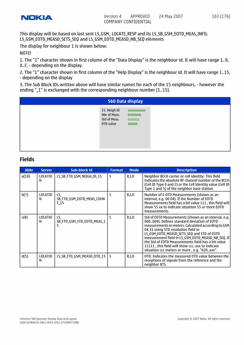
This display will be based on last sent LS_GSM_ LOCATE_RESP and its LS_SB_GSM_EOTD_MEAS_INFO,LS_GSM_EOTD_MEASD_SETS_SEQ and LS_GSM_EOTD_MEASD_NB_SEQ elements
The display for neighbour 1 is shown below:
NOTE!
1. The "1" character shown in first column of the "Data Display" is the neighbour id. It will have range 1..9,A..F, - depending on the display.
2. The "1" character shown in first column of the "Help Display" is the neighbour id. It will have range 1..15,- depending on the display
3. The Sub Block IDs written above will have similar names for each of the 15 neighbours, - however theending "_1" is exchanged with the corresponding neighbour number (1..15).
S60 Data display
aaaaaaaaaa15. Neigh IDbbbbbbbNbr of Meas.ccccccccStd of Meas.dddddOTD value
Fields
Abbr Server Sub-block id Format Mode Description
a(10) LOCATION
LS_SB_FTD_GSM_NEIGH_ID_15 S R,I,O Neighbor BCCH carrier or cell identity: This fieldindicates the absolute RF channel number of the BCCH(Cell ID Type 0 and 2) or the Cell Identity value (Cell IDType 1 and 5) of the neighbor base station.
b(7) LOCATION
LS_ SB_FTD_GSM_EOTD_MEAS_COUNT_15
S R,I,O Number of E-OTD Measurements (shown as aninterval, e.g. 00 04). If the Number of EOTDMeasurements field has a bit value 111 , this field willshow 55 xx to indicate situation 55 or more EOTDmeasurements
c(8) LOCATION
LS_ SB_FTD_GSM_STD_EOTD_MEAS_15
S R,I,O Std of EOTD Measurements (shown as an interval, e.g.000..009). Defines standard deviation of EOTDmeasurements in meters. Calculated according to GSM04.31 using STD resolution field inLS_GSM_EOTD_MEASD_SETS_SEQ and STD of EOTDmeasurement field in LS_GSM_EOTD_MEASD_NB_SEQ. Ifthe Std of EOTD Measurements field has a bit value11111 , this field will show ccc..xxx to indicatesituation ccc meters or more , e.g. "620..xxx".
d(5) LOCATION
LS_SB_FTD_GSM_MEASD_OTD_15 S R,I,O OTD: Indicates the measured OTD value between thereceptions of signals from the reference and theneighbor BTS.
Version 4 APPROVED 24 May 2007COMPANY CONFIDENTIAL
163 (176)
Common S60 Operator Display Data And Layout Copyright © 2007 Nokia. All rights reserved.GUID-629D4CCD-2861-4F43-9261-2F1E889728BA

15 Group 78: Email displays
15.1 Group 78 InformationThis group is for Email displays. Initially it consists of only BlackBerry displays. Blackberry is a proprietarywireless email protocol. Common email displays may be added later.
15.2 Display 78.01: BlackBerry - Registration APN informationNOTE!
This group is for Email displays. Initially it consists of only BlackBerry displays. Blackberry is a proprietarywireless email protocol. Common email displays may be added later.
S60 Data display
aaaaaaaaaaaaBB regist.
bbbbbbbbbbbbAPN used
ccccccccccccdddddddddddd
Fields
Abbr Server Sub-block id Format Mode Description
a(12) BLACKBERRY_EMAIL
FTD_ SB_BB_REGISTRATION_ROUTING_PART1
S R,O First 12 characters of the APN used for the registrationserver.
b(12) BLACKBERRY_EMAIL
FTD_ SB_BB_REGISTRATION_ROUTING_PART2
S R,O Second set of 12 characters of the APN used for theregistration server.
c(12) BLACKBERRY_EMAIL
FTD_ SB_BB_REGISTRATION_ROUTING_PART3
S R,O Third set of 12 characters of the APN used for theregistration server.
d(12) BLACKBERRY_EMAIL
FTD_ SB_BB_REGISTRATION_ROUTING_PART4
S R,O Fourth set of 12 characters of the APN used for theregistration server.
15.3 Display 78.02: BlackBerry - Registration and Routing information
S60 Data display
aaaaaaaa
local prt
BB Regis:
bbbbbIP address
cccccRemote prt
Version 4 APPROVED 24 May 2007COMPANY CONFIDENTIAL
164 (176)
Common S60 Operator Display Data And Layout Copyright © 2007 Nokia. All rights reserved.GUID-629D4CCD-2861-4F43-9261-2F1E889728BA

Fields
Abbr Server Sub-block id Format Mode Description
a(8) BLACKBERRY_EMAIL
FTD_ SB_BB_REGISTRATION_ROUTING_HOST
S R,O IP address of the registration host, 4 bytes expressedas 8 ASCII hex characters.
b(5) BLACKBERRY_EMAIL
FTD_ SB_BB_REGISTRATION_REMOTE_ROUTING_PORTS
S R,O Remote registration port, 2 bytes expressed as 4 ASCIIhex characters.
c(5) BLACKBERRY_EMAIL
FTD_ SB_BB_REGISTRATION_LOCAL_ROUTING_PORTS
S R,O Local registration port, 2 bytes expressed as 4 ASCIIhex characters.
15.4 Display 78.03: BlackBerry - Service APN information
S60 Data display
aaaaaaaaaaaaBB service
bbbbbbbbbbbbAPN used
ccccccccccccdddddddddddd
Fields
Abbr Server Sub-block id Format Mode Description
a(12) BLACKBERRY_EMAIL
FTD_ SB_BB_SERVICE_ROUTING_PART1
S R,O First 12 characters of the APN used for the serviceserver.
b(12) BLACKBERRY_EMAIL
FTD_ SB_BB_SERVICE_ROUTING_PART2
S R,O Second set of 12 characters of the APN used for theservice server.
c(12) BLACKBERRY_EMAIL
FTD_ SB_BB_SERVICE_ROUTING_PART3
S R,O Third set of 12 characters of the APN used for theservice server.
d(12) BLACKBERRY_EMAIL
FTD_ SB_BB_SERVICE_ROUTING_PART4
S R,O Fourth set of 12 characters of the APN used for theservice server.
15.5 Display 78.04: BlackBerry - Service information
Version 4 APPROVED 24 May 2007COMPANY CONFIDENTIAL
165 (176)
Common S60 Operator Display Data And Layout Copyright © 2007 Nokia. All rights reserved.GUID-629D4CCD-2861-4F43-9261-2F1E889728BA

S60 Data display
aaaaaaaa
local prt
BB Service:
bbbbbIP address
cccccRemote prt
Fields
Abbr Server Sub-block id Format Mode Description
a(8) BLACKBERRY_EMAIL
FTD_ SB_BB_SERVICE_ROUTING_HOST
S R,O IP address of the service host, 4 bytes expressed as 8ASCII hex characters.
b(5) BLACKBERRY_EMAIL
FTD_ SB_BB_SERVICE_REMOTE_ROUTING_PORTS
S R,O Remote service port, 2 bytes expressed as 4 ASCII hexcharacters.
c(5) BLACKBERRY_EMAIL
FTD_ SB_BB_SERVICE_LOCAL_ROUTING_PORTS
S R,O Local service port, 2 bytes expressed as 4 ASCII hexcharacters.
15.6 Display 78.05: BlackBerry - Last 4 events log
S60 Data display
aaaaaaaaaaaa
Last 4 events log (code)(time)
bbbbbbbbbbbbccccccccccccdddddddddddd
Fields
Abbr Server Sub-block id Format Mode Description
a(12) BLACKBERRY_EMAIL
FTD_SB_BB_EVENTLOG_1 S R,O Event code and time of last event
b(12) BLACKBERRY_EMAIL
FTD_SB_BB_EVENTLOG_2 S R,O Event code and time of last but one event
c(12) BLACKBERRY_EMAIL
FTD_SB_BB_EVENTLOG_3 S R,O Event code and time of last but two events
d(12) BLACKBERRY_EMAIL
FTD_SB_BB_EVENTLOG_4 S R,O Event code and time of last but three events
15.7 Display 78.06: BlackBerry - UDP traffic
Version 4 APPROVED 24 May 2007COMPANY CONFIDENTIAL
166 (176)
Common S60 Operator Display Data And Layout Copyright © 2007 Nokia. All rights reserved.GUID-629D4CCD-2861-4F43-9261-2F1E889728BA

S60 Data display
aaaaaaaa
UDP traffic send and
bbbbbbbbbbbb
receive info
cccccccc
snd
dddddddddddd
rcv
Fields
Abbr Server Sub-block id Format Mode Description
a(8) BLACKBERRY_EMAIL
FTD_ SB_BB_UDP_TRAFFIC_LASTSEND
S R,O Time of last sent packet. Blank if data has not beensent.
b(12) BLACKBERRY_EMAIL
FTD_SB_BB_UDP_TRAFFIC_SENT S R,O Number of datagrams sent and total length. The 2fields separated by a comma.
c(8) BLACKBERRY_EMAIL
FTD_ SB_BB_UDP_TRAFFIC_LASTRECEIVE
S R,O Time of last received packet. Blank if data has notbeen received.
d(12) BLACKBERRY_EMAIL
FTD_ SB_BB_UDP_TRAFFIC_RECEIVED
S R,O Number of datagrams received and total length. The2 fields separated by a comma.
15.8 Display 78.07: BlackBerry - Mail traffic
S60 Data display
aaaaaaaa
Mail traffic send and
bbbbbbbbbbbb
receive info
cccccccc
snd
dddddddddddd
rcv
Fields
Abbr Server Sub-block id Format Mode Description
a(8) BLACKBERRY_EMAIL
FTD_ SB_BB_MAIL_TRAFFIC_LASTSEND
S R,O Time of last sent mail.
b(12) BLACKBERRY_EMAIL
FTD_SB_BB_MAIL_TRAFFIC_SENT S R,O Number of mail sent and total length. The 2 fieldsseparated by a comma.
c(8) BLACKBERRY_EMAIL
FTD_ SB_BB_MAIL_TRAFFIC_LASTRECEIVE
S R,O Time of last received mail.
Version 4 APPROVED 24 May 2007COMPANY CONFIDENTIAL
167 (176)
Common S60 Operator Display Data And Layout Copyright © 2007 Nokia. All rights reserved.GUID-629D4CCD-2861-4F43-9261-2F1E889728BA

Abbr Server Sub-block id Format Mode Description
d(12) BLACKBERRY_EMAIL
FTD_ SB_BB_MAIL_TRAFFIC_RECEIVED
S R,O Number of mail received and total length. The 2 fieldsseparated by a comma.
15.9 Display 78.08: BlackBerry - NOC selectionWhen display is selected via the menu (not using the arrow buttons), the NOC selection field can be edited.Keyboard is in "text" mode, so hex numbers 0-F can be written. After editing is completed, the new selectedNOC is activated.
S60 Data display
aNOC SELECTION:
Use menu to select NOC
Fields
Abbr Server Sub-block id Format Mode Description
a BLACKBERRY_EMAIL
FTD_SB_BB_NOC_SELECTION B:H R,O Show NOC selection
INPUT BLACKBERRY_EMAIL
FTD_SB_BB_NOC_SET DW:H R,O Allow the tester to select a NOC. The value 0 is reservedto the production NOC
15.10 Display 78.09: BlackBerry - Reset UDP traffic counters
S60 Data display
Use menu to resetUDP traffic counters
Fields
Abbr Server Sub-block id Format Mode Description
EXE BLACKBERRY_EMAIL
FTD_SB_BB_UDP_ACTION_RESET B:D R,O Reset UDP counters.
15.11 Display 78.10: BlackBerry - Reset mail traffic counters
Version 4 APPROVED 24 May 2007COMPANY CONFIDENTIAL
168 (176)
Common S60 Operator Display Data And Layout Copyright © 2007 Nokia. All rights reserved.GUID-629D4CCD-2861-4F43-9261-2F1E889728BA

S60 Data display
Use menu to resetMail traffic counters
Fields
Abbr Server Sub-block id Format Mode Description
EXE BLACKBERRY_EMAIL
FTD_SB_BB_MAIL_ACTION_RESET B:D R,O Reset mail counters.
Version 4 APPROVED 24 May 2007COMPANY CONFIDENTIAL
169 (176)
Common S60 Operator Display Data And Layout Copyright © 2007 Nokia. All rights reserved.GUID-629D4CCD-2861-4F43-9261-2F1E889728BA

16 Group 81: Multimode protocol displays
16.1 Display 81.01: Force protocol between GSM and WCDMATo change Force Protocol status, perform following steps:
7. Press the Menu button.
8. Scroll in the main menu loop to field test display item.
9. Press the Select button.
10. Select this display in input mode by entering 8101 (Multimode protocol displays; Force protocol) to thequery prompt.
11. Test input prompt will activate, enter the Force Protocol status code (see the table below) in display.
12. Confirm with the Ok button.
S60 Data display
a
GSM and WCDMA
0-dual1-GSM2-WCDMA
Force protocol between
Fields
Abbr Server Sub-block id Format Mode Description
a GSS FTD_SB_SELECTED_RAT_READ B:D R,I,O Forced protocol:
0 = dual mode
1 = GSM
2 = WCDMA
255 = unknown
INPUT GSS FTD_SB_SELECTED_RAT_SET DW:D R,I,O Force protocol 0 = dual mode 1 = GSM 2 = WCDMA
16.2 Display 81.02: Toggle Integrity Protection ModeTo change integrity protection mode, perform following steps:
1. Press the Menu button.
2. Scroll in the main menu loop to field test display item.
3. Press the Select button.
4. Select this display in executive mode by entering 8102 (Multimode protocol displays;toggle integrityprotection mode) to the query prompt.
5. Confirm with the Ok button.
Version 4 APPROVED 24 May 2007COMPANY CONFIDENTIAL
170 (176)
Common S60 Operator Display Data And Layout Copyright © 2007 Nokia. All rights reserved.GUID-629D4CCD-2861-4F43-9261-2F1E889728BA

S60 Data display
aaa
protection mode on/offToggle intergrity
Fields
Abbr Server Sub-block id Format Mode Description
a(3) GSS FTD_SB_INT_PRO_MODE S R,I,O Current integrity protection mode:
ON : Enabled
OFF : Disabled
EXE GSS FTD_SB_INT_PRO_MODE_TOGGLE S R,I,O Toggle integrity protection mode.
Version 4 APPROVED 24 May 2007COMPANY CONFIDENTIAL
171 (176)
Common S60 Operator Display Data And Layout Copyright © 2007 Nokia. All rights reserved.GUID-629D4CCD-2861-4F43-9261-2F1E889728BA

17 Group 85: UMA
17.1 Display 85.01: (UMA) URR and URLC parameters
S60 Data display
aS F Ca
bC Ca Rin
cc
Rout HOtoG HOtoUd
ARFC BS LACB
ee fff
ggg hhh iii
jjjj kk llll
Fields
Abbr Server Sub-block id Format Mode Description
a GPDS FTD_SB_URR_STATE B:D R,I,O 1=URR Degistered, 2=URR Registered, 3=URR Idle,4=URR Dedicated
b GPDS FTD_SB_URR_SCAN_FREQUENCY S R,I,O WLAN scan frequence. H=High, M=Medium, L=Low.O=Off
c(2) GPDS FTD_SB_URR_CAUSE B:D R,I,O Last URR Discovery / Registration reject cause. Seevalues from UMA Stage 3 specification, Chapters11.2.12 and 11.2.21. Range 0-11. xx if not valid
d GPDS FTD_SB_URR_REGISTER_REATT B:D R,I,O UMA registration reattempt counter. Range 0-3.
e(2) GPDS FTD_SB_URLC_CAUSE B:D R,I,O Last URLC cause. See values from UMA Stage 3specification, Chapter 11.2.39. Range 0-13. xx if notvalid
f(3) GPDS FTD_SB_URR_ROVE_IN_CTR B:D R,I,O Counter for rove-in procedures. Range 0-255
g(3) GPDS FTD_SB_URR_ROVE_OUT_CTR B:D R,I,O Counter for rove-out procedures. Range 0-255
h(3) GPDS FTD_SB_URR_HO_TO_UMAN_CTR B:D R,I,O Counter for handover to UMAN procedures. Range0-255
i(3) GPDS FTD_SB_URR_HO_TO_GERAN_CTR B:D R,I,O Counter for handover to GERAN procedures. Range0-255
j(4) GPDS FTD_SB_URR_ARFCN W:H R,I,O ARFCN value for UMAN cell. Range 0-FFFF
k(2) GPDS FTD_SB_URR_BSIC B:H R,I,O BSIC value for UMAN cell. Range 0-FF
l(4) GPDS FTD_SB_URR_LAC_BLACKLIST W:H R,I,O LAC (Location Area Code) which is blacklisted. Range0-FFFF
17.2 Display 85.02: (UMA) UNC and SGW IP addresses
Version 4 APPROVED 24 May 2007COMPANY CONFIDENTIAL
172 (176)
Common S60 Operator Display Data And Layout Copyright © 2007 Nokia. All rights reserved.GUID-629D4CCD-2861-4F43-9261-2F1E889728BA

S60 Data display
aT UNC-IPaddr
bbbIPaddr cont
ccc
SGW-IPaddrddd
IPaddr cont
eee
fff ggg hhh
iii
Fields
Abbr Server Sub-block id Format Mode Description
a GPDS FTD_SB_URR_ADDR_TYPE B:D R,I,O 4=IPv4, 6=IPv6
b(3) GPDS FTD_SB_URR_UNC_ADDRESS_1 B:D R,I,O The UNC IP address, part 1. Currently only IPv4 issupported.
c(3) GPDS FTD_SB_URR_UNC_ADDRESS_2 B:D R,I,O The UNC IP address, part 2. Currently only IPv4 issupported.
d(3) GPDS FTD_SB_URR_UNC_ADDRESS_3 B:D R,I,O The UNC IP address, part 3. Currently only IPv4 issupported.
e(3) GPDS FTD_SB_URR_UNC_ADDRESS_4 B:D R,I,O The UNC IP address, part 4. Currently only IPv4 issupported.
f(3) GPDS FTD_SB_URR_SGW_ADDRESS_1 B:D R,I,O The SGW IP address, part 1. Currently only IPv4 issupported.
g(3) GPDS FTD_SB_URR_SGW_ADDRESS_2 B:D R,I,O The SGW IP address, part 2. Currently only IPv4 issupported.
h(3) GPDS FTD_SB_URR_SGW_ADDRESS_3 B:D R,I,O The SGW IP address, part 3. Currently only IPv4 issupported.
i(3) GPDS FTD_SB_URR_SGW_ADDRESS_4 B:D R,I,O The SGW IP address, part 4. Currently only IPv4 issupported.
Version 4 APPROVED 24 May 2007COMPANY CONFIDENTIAL
173 (176)
Common S60 Operator Display Data And Layout Copyright © 2007 Nokia. All rights reserved.GUID-629D4CCD-2861-4F43-9261-2F1E889728BA

18 Group 86: WLAN displays
18.1 Display 86.01: WLAN Device InfoThis display contains static WLAN information.
S60 Data display
aaaaaaaaaaaaMac address
bbbbbHW version
cccccccccccFW version
Fields
Abbr Server Sub-block id Format Mode Description
a(12) WLAN FTD_SB_WLAN_OWN_MAC_ADDR S R,I,O Phone's WLAN MAC address
b(5) WLAN FTD_SB_WLAN_HW_ERSION S R,I,O WLAN chip HW version
c(11) WLAN FTD_SB_WLAN_FW_VERSION S R,I,O WLAN chip FW version
18.2 Display 86.02: WLAN Connection Info 1This display contains information about the current connection. xx shown on all fields when there is notconnection.
S60 Data display
aaaaaaaaaaaaSSID
bbbbbbbbbbbbMAC address
ccch
dddrssi
Fields
Abbr Server Sub-block id Format Mode Description
a(12) WLAN FTD_SB_WLAN_SSID S R,I,O SSID (=access point's name)
b(12) WLAN FTD_SB_WLAN_AP_MAC_ADDR S R,I,O AP's WLAN MAC address
c(2) WLAN FTD_SB_WLAN_CHANNEL B:D R,I,O Channel number (e.g. 802.11b/g 1-13)
d(3) WLAN FTD_SB_WLAN_RSSI B:D R,I,O Signal strength (in dB)
18.3 Display 86.03: WLAN Connection Info 2This display contains information about the current connection. xx shown on all fields when there is notconnection.
Version 4 APPROVED 24 May 2007COMPANY CONFIDENTIAL
174 (176)
Common S60 Operator Display Data And Layout Copyright © 2007 Nokia. All rights reserved.GUID-629D4CCD-2861-4F43-9261-2F1E889728BA

S60 Data display
aaaarates 11bbbbbbbbbbrates 11gcccccccccapabilitLSBddddddddcapabilitMSB
Fields
Abbr Server Sub-block id Format Mode Description
a(4) WLAN FTD_SB_WLAN_RATES_11B S R,I,O Access point's supported 802.11b rates (1-11 Mbit/s).Each character corresponds to a rate as follows:1 2 5.511 Mbps- = not supported rateB = basic rate(=mandatory for all stations) S = supported rateE.g.,BBS- means that 1 and 2 are the basic rates for theaccess point, 5.5 is an optional rate, and 11 is a notsupported rate.
b(9) WLAN FTD_SB_WLAN_RATES_11G S R,I,O Access point's supported 802.11g rates (6-54 Mbit/s).Each character corresponds to a rate as follows:6 9 1218 22 24 36 48 54 Mbps - = not supported rateB = basicrate (=mandatory for all stations) S = supported rate
c(8) WLAN FTD_SB_WLAN_CAPABILITY_LSB S R,I,O Access point capabilitites bit-map (LSB). 1 means thatthe AP supports the feature, and 0 means that the APdoes not support the feature. The meaning of the bitsare as follows (bit 1 is the leftmost bit, and bit 8 is therightmost bit:Bit 1 ESSBit 2 IBSSBit 3 CF PollableBit 4CF Poll RequestBit 5 PrivacyBit 6 Short PreambleBit 7PBCCBit 8 Channel Agility
d(8) WLAN FTD_SB_WLAN_CAPABILITY_MSB S R,I,O Access point capabilitites bit-map (MSB).1 means thatthe AP supports the feature, and 0 means that the APdoes not support the feature. The meaning of the bitsare as follows (bit 1 is the leftmost bit, and bit 8 is therightmost bit:Bit 1 Spectrum managementBit 2QoSBit 3 Short Slot TimeBit 4 APSDBit 5 -Bit 6 DSSS-OFDMBit 7 Delayed Block AckBit 8 Immediate Block Ack
18.4 Display 86.04: WLAN StatisticsStatistics for the current WLAN connection. The counters are reset when a new connection is made. xx shownon all fields when there is not connection.
Calculation of average values is currently OPEN.
Resetting of the counters is OPEN.
Version 4 APPROVED 24 May 2007COMPANY CONFIDENTIAL
175 (176)
Common S60 Operator Display Data And Layout Copyright © 2007 Nokia. All rights reserved.GUID-629D4CCD-2861-4F43-9261-2F1E889728BA

S60 Data display
aaTxRatebbRXRatecccccULTPdddddDLTPeeeeeULBytefffffDLByte
Fields
Abbr Server Sub-block id Format Mode Description
a(2) WLAN FTD_SB_WLAN_AV_TX_RATE B:D R,I,O Average WLAN data frame tx rate
b(2) WLAN FTD_SB_WLAN_AV_RX_RATE B:D R,I,O Average WLAN data frame rx rate
c(5) WLAN FTD_SB_WLAN_UL_THROUGHPUT W:D R,I,O Average uplink (user data) throughput
d(5) WLAN FTD_SB_WLAN_DL_THROUGHPUT W:D R,I,O Average downlink (user data) throughput
e(5) WLAN FTD_SB_WLAN_UL_BYTES W:D R,I,O Amount of transmitted user data (in kilobytes)
f(5) WLAN FTD_SB_WLAN_DL_BYTES W:D R,I,O Amount of received user data (in kilobytes)
18.5 Display 86.05: Blacklisted APs 1List of blacklisted access points. Reset when power is switched off. If there are more than four black listedAPs, only the first four are shown. If there are less than four blacklisted APs, xx is shown for the empty places.
S60 Data display
aaaaaaaaaaaaMac addr AP1
bbbbbbbbbbbbMac addr AP2
ccccccccccccMac addr AP3
ddddddddddddMac addr AP4
Fields
Abbr Server Sub-block id Format Mode Description
a(12) WLAN FTD_ SB_WLAN_BLACKLIST_ADDR_1
S R,I,O MAC address of a blacklisted AP 1
b(12) WLAN FTD_ SB_WLAN_BLACKLIST_ADDR_2
S R,I,O MAC address of a blacklisted AP 2
c(12) WLAN FTD_ SB_WLAN_BLACKLIST_ADDR_3
S R,I,O MAC address of a blacklisted AP 3
d(12) WLAN FTD_ SB_WLAN_BLACKLIST_ADDR_4
S R,I,O MAC address of a blacklisted AP 4
Version 4 APPROVED 24 May 2007COMPANY CONFIDENTIAL
176 (176)
Common S60 Operator Display Data And Layout Copyright © 2007 Nokia. All rights reserved.GUID-629D4CCD-2861-4F43-9261-2F1E889728BA
Related Documents