Commissioning Water Systems By Chris Parsloe BG 2/2010 A BSRIA Guide www.bsria.co.uk

Welcome message from author
This document is posted to help you gain knowledge. Please leave a comment to let me know what you think about it! Share it to your friends and learn new things together.
Transcript

Commissioning Water Systems
By Chris Parsloe
BG 2/2010
A BSRIA Guide www.bsria.co.uk


COMMISSIONING WATER SYSTEMS 1
© BSRIA BG 2/2010
AcknowledgementsThe first edition of the publication BSRIA Application Guide, AG 2/89: Commissioning of water systems in buildings was produced as part of a research project in 1989 under the sponsorship of the Department of the Environment, Construction Directorate, and under the direction of an industry steering group.
This new fully revised edition has been compiled with the help of a joint BSRIA – CIBSE industry steering group under the chairmanship of Bryan Franklin, and designed and produced by Ruth Radburn. The steering group members were:
AECOM Mike Campbell Arup Terry Dix Ashford Environmental Services Roger Carlin Banyards Nick Till Barfield Peter Barrett Belimo Luke Collier Burgess Group George Moss Commtech Nick Ward Crane Andy Lucas Crown House Malcolm Moorby Commissioning Specialists Association John Coppin
Danfoss Paul Wightman End Systems Brian Townsend Frese Matthew Dunk Raxcrest Terry Dodge SAV Lars Fabricius SES Chris Driscoll Siemens Building Technologies Gerry McGilley Sutton Bill McCluskey Wates Lee Hansard
BSRIA acknowledges the very significant contribution made by all the steering group members, but the responsibility for the document remains with BSRIA.
We would also like to thank our author, Chris Parsloe, the team at CIBSE, Hywel Davies and Claire Ruston, and all those who contributed photographs for the Guide.
©BSRIA BG 2/2009 June 2010 ISBN 978 0 86022 689 5 Printed by ImageData Ltd
All rights reserved. No part of this publication may be reproduced, stored in a retrieval system, or transmitted in any form or by any means electronic or mechanical including photocopying, recording or otherwise without prior written permission of the publisher.
This publication has been printed on Nine Lives Silk recycled paper, which is manufactured from 100% recycled fibre.

2 COMMISSIONING WATER SYSTEMS
© BSRIA BG 2/2010
Preface
Bryan Franklin.
To be written …..
By Brian Franklin May 2010
Photo of Bryan Franklin
COMMISSIONING WATER SYSTEMS 3
© BSRIA BG 2/2010
ContentsDefinitions 6
Abbreviations 7
List of symbols 8
1 Introduction 91.1 Building Regulations Part L 91.2 Guide content 9
2 Design for commissionability 102.1 Commissioning specification 102.2 Pipe system commissionability 112.3 Pipe system layout 122.4 Pipe sizing 122.5 Pump sizing 132.6 Commissioning devices 132.7 Ultra low flow rates 132.8 Pre-commission cleaning provisions 142.9 Venting provisions 142.10 De-aeration 142.11 Provisions for measuring pressure 152.12 Tolerances 15
3 Commissioning devices 193.1 Regulating valves 213.2 Flow measurement principles 233.3 Flow measurement devices (FMDs) 233.4 Improvised flow measurement 253.5 Combined flow measurement and regulation device 273.6 Constant flow regulator (CFR) 293.7 Differential pressure control valves (DPCVs) 303.8 Pressure independent control valves (PICVs) 323.9 Guidelines for locating commissioning devices 34
4 The installation of commissionable systems 354.1 Organisation and planning 354.2 Installation issues affecting commissionaibility 364.3 Housekeeping 364.4 Workmanship 364.5 Installation of commissioning devices 364.6 Accessibility 374.7 Draining provisions 384.8 Venting 384.9 Installation inspections 394.10 Preparation for commissioning 40
4 COMMISSIONING WATER SYSTEMS
© BSRIA BG 2/2010
5 Site test instruments 415.1 Rotational speed measurement 415.2 Voltage and current measurement 425.3 Flow measurement 425.4 Pressure measurement 455.5 BSRIA recommended test kit 45
6 Commissioning procedures 476.1 Organisation and planning 476.2 Setting to work 476.3 Full system scan 486.4 Regulation procedure 486.5 Proportional balancing 496.6 Flow setting 536.7 Flow measurement accuracy 54
7 Example method statements 557.1 Primary circuits 557.2 Constant flow secondary circuits 567.3 Variable flow secondary circuits 607.4 Setting of total flow rate from the pump 66
8 Reporting and documentation 678.1 Reporting 678.2 Documentation 678.3 Example pro formas 67
AppendicesAppendix: A Flow rate tolerances 79
Appendix: B Proportional balancing procedure using measurements of pressure differential 80
COMMISSIONING WATER SYSTEMS 5
© BSRIA BG 2/2010
TablesTable 1: Recommended range of maximum water velocities. 12Table 2: Suggested tolerances for flow regulation in heating systems 16Table 3: Suggested tolerances for flow regulation in chilled water systems 17Table 4: Commissioning device, terminologies and functions. 20Table 5: Valve applications. 34Table 6: Minimum straight lengths recommended upstream and downstream of flow
measurement devices. 37Table 7: BSRIA-recommended test kit. 46Table 8: Tolerances for flow rate balancing in heating systems. 79Table 9: Tolerances for flow rate balancing in heating systems. 79Table 10: Regulation of terminal unit with interpretation of measurements. 80
FiguresFigure 1: Heat transfer sensitivity for alternative heating and cooling coils. 18Figure 2: Double-regulating globe valves. 22Figure 3: Double-regulating butterfly. 22Figure 4: Typical fixed-orifice fittings. 24Figure 5: Flow rate measurements using fixed resistances. 26Figure 6: Flow rate measurements in circuits with PICVs. 26Figure 7: Flow rate measurements in circuits fed from manifolds. 27Figure 8: Typical fixed-orifice double-regulating valves. 28Figure 9: Typical variable orifice double regulating valves. 29Figure 10: Cartridge type constant flow regulator. 30Figure 11: Differential pressure control valves. 31Figure 12: Pressure independent control valves. 33Figure 13: 0 - 65 kPa. 44Figure 14: Digital differential pressure and flow rate instrument. 45Figure 15: The basis of proportional balancing. 50Figure 16: Typical primary circuit arrangement. 55Figure 17: A system feeding to fan coil units. 57Figure 18: A constant flow system serving fan coil units. 59Figure 19: A system feeding to radiators. 61Figure 20: A variable flow system serving fan coil units. 63Figure 21: A variable flow system serving fan coil units. 65
6 COMMISSIONING WATER SYSTEMS
© BSRIA BG 2/2010
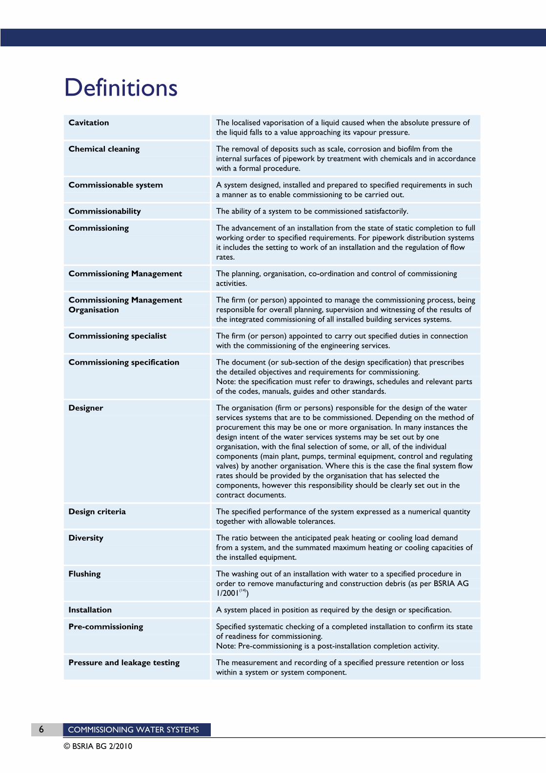
DefinitionsCavitation The localised vaporisation of a liquid caused when the absolute pressure of
the liquid falls to a value approaching its vapour pressure.
Chemical cleaning The removal of deposits such as scale, corrosion and biofilm from the internal surfaces of pipework by treatment with chemicals and in accordance with a formal procedure.
Commissionable system A system designed, installed and prepared to specified requirements in such a manner as to enable commissioning to be carried out.
Commissionability The ability of a system to be commissioned satisfactorily.
Commissioning The advancement of an installation from the state of static completion to full working order to specified requirements. For pipework distribution systems it includes the setting to work of an installation and the regulation of flow rates.
Commissioning Management The planning, organisation, co-ordination and control of commissioning activities.
Commissioning Management Organisation
The firm (or person) appointed to manage the commissioning process, being responsible for overall planning, supervision and witnessing of the results of the integrated commissioning of all installed building services systems.
Commissioning specialist The firm (or person) appointed to carry out specified duties in connection with the commissioning of the engineering services.
Commissioning specification The document (or sub-section of the design specification) that prescribes the detailed objectives and requirements for commissioning. Note: the specification must refer to drawings, schedules and relevant parts of the codes, manuals, guides and other standards.
Designer The organisation (firm or persons) responsible for the design of the water services systems that are to be commissioned. Depending on the method of procurement this may be one or more organisation. In many instances the design intent of the water services systems may be set out by one organisation, with the final selection of some, or all, of the individual components (main plant, pumps, terminal equipment, control and regulating valves) by another organisation. Where this is the case the final system flow rates should be provided by the organisation that has selected the components, however this responsibility should be clearly set out in the contract documents.
Design criteria The specified performance of the system expressed as a numerical quantity together with allowable tolerances.
Diversity The ratio between the anticipated peak heating or cooling load demand from a system, and the summated maximum heating or cooling capacities of the installed equipment.
Flushing The washing out of an installation with water to a specified procedure in order to remove manufacturing and construction debris (as per BSRIA AG 1/2001(14))
Installation A system placed in position as required by the design or specification.
Pre-commissioning Specified systematic checking of a completed installation to confirm its state of readiness for commissioning. Note: Pre-commissioning is a post-installation completion activity.
Pressure and leakage testing The measurement and recording of a specified pressure retention or loss within a system or system component.
COMMISSIONING WATER SYSTEMS 7
© BSRIA BG 2/2010
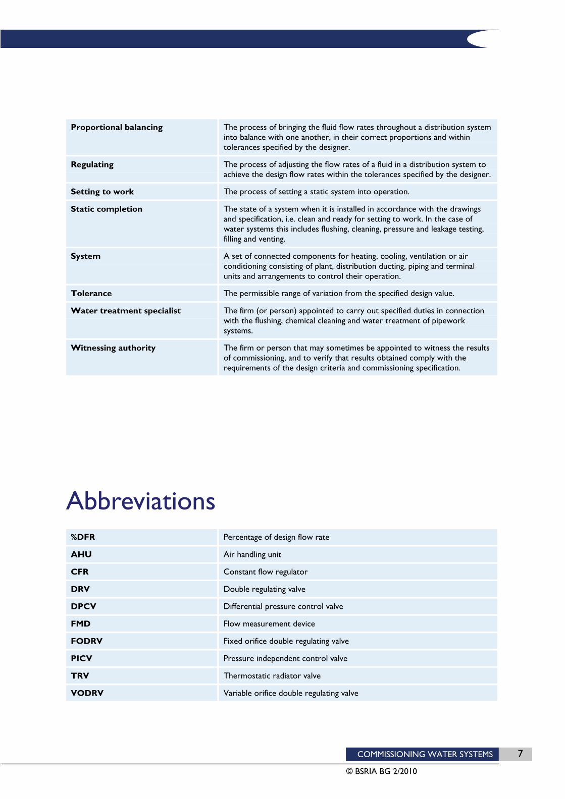
Proportional balancing The process of bringing the fluid flow rates throughout a distribution system into balance with one another, in their correct proportions and within tolerances specified by the designer.
Regulating The process of adjusting the flow rates of a fluid in a distribution system to achieve the design flow rates within the tolerances specified by the designer.
Setting to work The process of setting a static system into operation.
Static completion The state of a system when it is installed in accordance with the drawings and specification, i.e. clean and ready for setting to work. In the case of water systems this includes flushing, cleaning, pressure and leakage testing, filling and venting.
System A set of connected components for heating, cooling, ventilation or air conditioning consisting of plant, distribution ducting, piping and terminal units and arrangements to control their operation.
Tolerance The permissible range of variation from the specified design value.
Water treatment specialist The firm (or person) appointed to carry out specified duties in connection with the flushing, chemical cleaning and water treatment of pipework systems.
Witnessing authority The firm or person that may sometimes be appointed to witness the results of commissioning, and to verify that results obtained comply with the requirements of the design criteria and commissioning specification.
Abbreviations %DFR Percentage of design flow rate
AHU Air handling unit
CFR Constant flow regulator
DRV Double regulating valve
DPCV Differential pressure control valve
FMD Flow measurement device
FODRV Fixed orifice double regulating valve
PICV Pressure independent control valve
TRV Thermostatic radiator valve
VODRV Variable orifice double regulating valve
8 COMMISSIONING WATER SYSTEMS
© BSRIA BG 2/2010
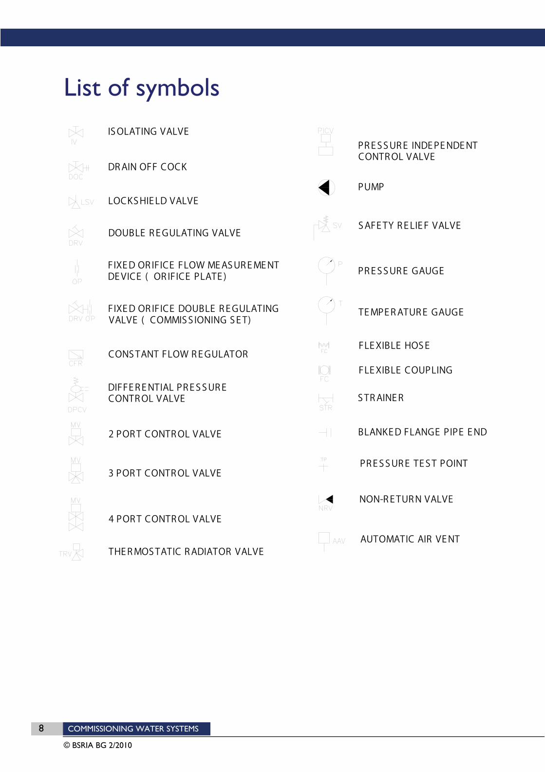
List of symbols I S O L A T I N G V A L V E
4 P O R T C O N T R O L V A L V E
P R E S S U R E T E S T P O I N T
N O N - R E T U R N V A L V E
D R A I N O F F C O C K
C O N S T A N T F L O W R E G U L A T O R
P R E S S U R E G A U G E
T E M P E R A T U R E G A U G E
F L E X I B L E H O S E
S T R A I N E R
F L E X I B L E C O U P L I N G
T H E R M O S T A T I C R A D I A T O R V A L V E
L O C K S H I E L D V A L V E
D I F F E R E N T I A L P R E S S U R E
C O N T R O L V A L V E
A U T O M A T I C A I R V E N T
F I X E D O R I F I C E F L O W M E A S U R E M E N T
D E V I C E ( O R I F I C E P L A T E )
D O U B L E R E G U L A T I N G V A L V E
F I X E D O R I F I C E D O U B L E R E G U L A T I N G
V A L V E ( C O M M I S S I O N I N G S E T )
2 P O R T C O N T R O L V A L V E
3 P O R T C O N T R O L V A L V E
P U M P
P R E S S U R E I N D E P E N D E N T
C O N T R O L V A L V E
S A F E T Y R E L I E F V A L V E
B L A N K E D F L A N G E P I P E E N D

COMMISSIONING WATER SYSTEMS 9
© BSRIA BG 2/2010
1 Introduction This Guide explains how to commission water pipework distribution systems in buildings. The commissioning process mainly comprises the setting to work of the system pumps and the regulation (or proportional balancing) of system flow rates.
The procedures set out in this guide, if undertaken, should achieve compliance with the requirements of CIBSE Code W Water Distribution Systems. In general, CIBSE Code W sets out the normal standards of good practice which are generally accepted within the building services industry. This guide explains how to carry out the commissioning procedure in a way that ensures these standards are achieved.
The emphasis of this guide is on building heating and cooling systems although it may also be applied to other types of water distribution systems in buildings and industry. The guide is equally applicable to new-build and retrofit applications and is independent of the scale of the system.
Compliance with the requirements of this guide does not confer immunity from relevant statutory and legal requirements.
1.1 BUILDING REGULATIONS PART L
Part L1 of the Building Regulations in England and Wales requires that “reasonable provision shall be made for the conservation of fuel and power in buildings by providing and commissioning energy efficient fixed building services with effective controls”.
The approved procedure by which compliance with Part L can be demonstrated is that set out in CIBSE Code M Commissioning Management, and, for pipework distribution systems, its sub-referenced document CIBSE Code W Water Distribution Systems.
1.2 GUIDE CONTENT
The technical guidance is sub-divided into the following section headings:
Section 2: Design for commissionability
Section 3: Commissioning devices
Section 4: Installation for commissionability
Section 5: Site test instruments
Section 6: Commissioning procedures
Section 7: Example method statements
Section 8: Documentation and reporting
Sections 2 and 4 of the guide are deliberately aimed at system designers and installers. Unless commissioning is properly considered during both the design and installation stages of a project, it may not be possible to meet the requirements of CIBSE Code W.
Section 3 provides a summary of the main commissioning devices available at the time of writing.
Sections 5, 6, 7 and 8 are intended as guidance for commissioning specialists employed to undertake commissioning activities.
10 COMMISSIONING WATER SYSTEMS
© BSRIA BG 2/2010
2 Design for commissionability Designers and project managers should address their attention to commissioning and the effective management of the process as soon as possible after embarking on a scheme design stage.
Guidance on the management of the commissioning process is provided in the following publications:
CIBSE Code M, Commissioning Management.
BSRIA Guide BG6/2009, A Design Framework for Building Services
BSRIA Guide BG1/2009, Building Services Job Book
BSRIA Guide BG8/2009, Model Commissioning Plan
All commissioning activities should be planned and managed following the principles outlined in these guides.
2.1 COMMISSIONING SPECIFICATION
To enable a water distribution system to be successfully commissioned, the designer must provide adequate information, documented in the form of drawings, schedules and specification clauses. These documents are collectively known as the “commissioning specification”.
The commissioning specification for pipework systems should be developed by the designer to comprise:
1. The scope of the works i.e. the systems to be commissioned, their function and intended operation, and an explanation of their inter-relationships with other engineering systems
2. The setting out of the responsibilities of the various parties (for example the client, design team, main or managing contractor, installation contractor and commissioning specialist). BSRIA Guide BG6/2009 A Design Framework for Building Services and BSRIA Guide BG8/2009, Model Commissioning Plan give advice on the allocation of responsibilities for commissioning activities
3. The technical requirements of the commissioning work. For example:
the standards with which the works should comply (for example CIBSE Codes, and BSRIA guides)
the limiting flow measurement tolerances for flow measurement test results (as advised in section 2.12 of this guide)
the reporting procedures required for demonstrating the commissioning results
the witnessing procedures to be observed.
4. Design drawings showing the layout of pipe systems in relation to the building form and the other engineering services. The drawings should also include any schematic diagrams that illustrate the design intent and include all the design information required to commission the system. This would include, for example:
flow rates in all pipe branches and circuits
the positions of all valves and flow measurement devices, with each unique type having its own specific drawing symbol
a unique identification number for all valves and flow measurement devices that can be referenced to a separate valve schedule (Note the allocation of identification numbers may sometimes be completed by the installing contractor or commissioning specialist)
flow rates and manufacturers’ quoted pressure drops across heat emitters, heat exchangers and other items of plant
COMMISSIONING WATER SYSTEMS 11
© BSRIA BG 2/2010
flow rates and manufacturers’ quoted kv values and pressure drops across automatic control valves
anticipated design pressure drops throughout the distribution system covering, as a minimum, the whole of the index circuit, risers and main branches
draw-off rates for cold water and domestic hot water systems
regulating devices approved by the local water company to control cold water and domestic hot water systems
cold feed, pressurisation unit, feed and expansion tank points of connection
provisions for system flushing and bypass connections to main plant, together with a typical terminal detail of the bypass.
5. Schedules of major plant, equipment and components should be created, and cross-referenced to the design drawings and schematic diagrams. These would include, for example:
pumps: duty, impeller size, speed and characteristic curves
boilers: duty, operating temperatures and pressure.
6. Additional design information required for commissioning (which may not be available until after the appointment of the building services installer) and which may include:
electrical wiring diagrams of associated plant and equipment
control system diagrams
flow measurement devices: identification number, size, flow rate, pressure drop and signal flow coefficient (kvs)
double regulating valves: identification number, size, flow rate, pressure drop and valve kv
terminal units: identification number, design flow and return temperatures; flow rates and pressure drops
control valves: identification number, flow rate and pressure drop, and kv
heat exchangers: identification number, flow rate and pressure drop, primary and secondary flow and return temperatures
glands: highlight all glands and other components used in the system made from materials likely to be affected by chemical cleaning
differential pressure control valves: maximum and minimum operating differential pressures, design maximum flow rates and full open kv values for each valve
pressure independent control valves: maximum and minimum operating differential pressures, design flow rate value and full open kv value for each valve.
2.2 PIPE SYSTEM COMMISSIONABILITY
The ease with which the flow rates in a pipework system can be regulated is often dependent on the level of planning that occurs at the design stage. The objective should be to design a commissionable system that is easy to regulate and trouble-free in operation.
The following sections 2.3 – 2.12 explain the main issues that need to be considered during design.

12 COMMISSIONING WATER SYSTEMS
© BSRIA BG 2/2010
2.3 PIPE SYSTEM LAYOUT
One aim of pipe system design should be to avoid the need to generate high artificial resistances in branches in order to achieve the correct balance of flow rates. High resistances will inevitably need to be generated by tightly throttled valves which are more likely to generate noise and become blocked during normal operation.
The need for tightly throttled regulating valves can be avoided by considering the following design options:
The avoidance of branches serving large numbers of terminal units where the estimated pressure losses in the pipework connecting between the terminals (flow and return summated) are greater than 10kPa
The avoidance of parallel branches serving widely different numbers of terminal units. For example a circuit feeding 15 terminal units should, ideally not be installed from the same pipe run as a circuit feeding only 2 terminal units. Instead the circuits should be re-configured so that they have approximately equal numbers of terminal units
The avoidance of terminal units with significantly different design pressure drops and/or heat emitting characteristics on the same branch. For example, low resistance radiators or radiant panels should, ideally, not be installed on the same pipe run as high-resistance fan-coil units or chilled beams
The application of reverse-return pipe circuits for horizontal branch mains. Reverse return circuits work well because the available pressure differential across each sub-branch is approximately constant. There is therefore no need to limit the pressure losses in pipes connecting between terminals
The use of flow and return manifolds for final feed to terminal units, to equalise pressure differentials across terminal unit branches. As in the case of reverse return circuits, the available pressure differential across each sub-branch is approximately a constant value.
2.4 PIPE SIZING
Pipe sizes will normally be determined by the designer’s chosen range of acceptable pressure drops per metre pipe length (typically between 50 and 250 Pa/m for main distribution branches). Systems designed with pressure losses significantly above this range will incur additional pump energy consumption. Furthermore, there will be a greater risk of the installed pump being undersized relative to the installed system since each additional bend or pipe length inadvertently added by the installer will generate a higher pressure differential.
It is also important, where possible, to maintain maximum velocities within the range of recommended values given in Table 1. Excessive flow velocities may give rise to noise generation and erosion of system components. Therefore, the maintenance of velocities within the maximums indicated in Table 1 must take precedence in situations when sizing to a Pa/m limit might suggest a smaller pipe.
Table 1: Recommended range of maximum water velocities.
Pipe diameter (mm) Recommended maximum velocity limits (m/s)
Maximum
Copper Steel
15-50 1.0 1.5
Over 50 1.5 3
Low velocities may also give rise to issues of air and dirt settlement as discussed in BSRIA Application Guide, AG 1/2001.1: Pre-Commission Cleaning of Pipework Systems
COMMISSIONING WATER SYSTEMS 13
© BSRIA BG 2/2010
2.5 PUMP SIZING
The design of a multi-circuit water distribution system should include a calculation of the pressure loss through each circuit at the design water flow rate. The circuit that is estimated to have the largest pressure loss is known as the index circuit. Usually, (but not always) this is the circuit serving the terminal unit located furthest from the pump.
Pumps should be selected to deliver the maximum design flow rate (plus a margin of 10% for commissioning purposes) against the estimated pressure loss around the index circuit. The pump operating point must be located within the pump manufacturer’s recommended operating range for the particular pump selected.
In systems with load diversity, the pump should be sized to deliver the maximum simultaneous flow rate versus the pressure loss in the index circuit, with each pipe in the circuit carrying its anticipated peak flow rate.
Pumps should ideally be selected that permit the speed setting to be electronically varied to suit the flow conditions. Even if the pump serves a constant flow system, an energy saving will be achieved by varying pump speed to achieve the design flow rate as opposed to the use of a regulating valve. The Building Regulations for England and Wales Part L gives credit for installing variable speed pumps in heating distribution systems.
For variable flow systems, the pump should ideally be selected such that its operating point at full load lies close to but slightly to the right of the peak efficiency point of the pump. As the system resistance increases under part load conditions, the steepening of the system curve relative to the pump curve will then ensure that good efficiency is maintained at all times.
2.6 COMMISSIONING DEVICES
System designs should incorporate details of the commissioning valves and flow measurement devices required to facilitate the commissioning process, including their type, size and location in the system. There is now a wide variety of products available. The main types available at the time of writing are described in section 3 of this guide.
2.7 ULTRA LOW FLOW RATES
The designer should be aware of the need to deal with ultra low flow rates when they arise.
The term “ultra low flow rate” is generally applied to a flow rate which is too low to be regulated or measured by standard commissioning products.
In general any flow rate that is below 0.015 l/s is at risk of falling into the category of an ultra low flow. The main problems that might be encountered are as follows.
pipes feeding to terminal branches may be difficult to flush, and may become prone to air or dirt settlement in the pipes due to the very low pipe velocities generated
commercially available flow measurement devices may be unable to generate a signal of greater than 1kPa making it difficult to obtain accurate and repeatable flow measurements
the required flow rate may be below the setting range of pressure independent control valves (PICVs).
Ultra low flow rates are increasingly specified by designers, particularly for heating systems, due to a trend towards smaller heating loads in modern well insulated buildings. Furthermore, larger design temperature differentials (and hence lower flow rates) are more common in order to make better use of environmentally friendly heat sources.
Where ultra low flow rates are specified, the designer should decide on an appropriate course of action for commissioning, and should consult with the commissioning specialist accordingly.
14 COMMISSIONING WATER SYSTEMS
© BSRIA BG 2/2010
Options for dealing with ultra low flow rates include:
installing small bore pipes to maintain system velocities and avoid air and dirt settlement
adopting an improvised method of flow measurement as described in section 3.4
regulating system flow rates based on a temperature balance, the same as for radiator circuits
temporarily increasing terminal branch flow rates (by throttling other branches) until measureable flow rates are achieved thereby enabling a balance to be achieved.
2.8 PRE-COMMISSION CLEANING PROVISIONS
System cleanliness is of prime importance as dirt in a pipework system can adversely affect the accuracy and repeatability of flow measurements. Adequate facilities must be included at the design stage so that the system can be flushed and chemically cleaned to remove debris.
Specific features will be required in order to execute the flushing and cleaning processes properly (such as strainers, vent points, flushing by-passes and flushing drains). The designer should clearly detail such requirements in the drawings and explain the installer’s obligations in the specification.
BSRIA Application Guide, AG 1/2001.1: Pre-Commission Cleaning of Pipework System includes information on the provisions which need to be incorporated so that a system can be properly flushed and chemically cleaned.
2.9 VENTING PROVISIONS
Excessive air trapped within a pipework system during the initial fill can cause pump surging and air locks.
Facilities must be built into the pipework system to enable air to be vented during the initial fill. These facilities can take the form of manual or automatic air vents located:
at system high points;
in low loss headers;
at the tops of risers;
at terminal units;
in pipes connecting to central plant items such as pumps, boilers and chillers.
In addition, some systems may benefit from the inclusion of de-aerators, as described in section 2.10.
2.10 DE-AERATION
Manual venting of air in large or complex systems, or installations in high rise buildings, may prove difficult. If not properly vented, trapped air pockets may be dislodged by the flow of water when pumps are switched on. Once moving with the fluid, the air breaks down into small “micro-bubbles” that can cause non-repeatability of flow measurements i.e. over a period of time the flow rate may gradually reduce from its previously set value.
In large or tall systems, air bubbles may be generated as dissolved gas within the system water comes out of solution due either to increased water temperature through boilers, or the gradual reduction in static pressure as the water travels up vertical risers. These effects may again result in non-repeatability of flow measurements.
Air in the form of small entrained micro-bubbles is difficult to remove by normal venting. The smaller the bubbles, the less natural buoyancy they have and therefore the less likely they are to settle out at high points where vents may be located.

COMMISSIONING WATER SYSTEMS 15
© BSRIA BG 2/2010
For systems that are difficult to vent by manual means, some form of de-aeration facility is advisable. A purpose designed de-aeration unit can be installed in order to remove air from the system before commissioning, with the option to leave it in place permanently. If installed as an aid to commissioning, time will need to be allowed in the commissioning programme to allow the process of air removal to work. This may take a number of days depending on the size and type of de-aerator used and the size of the system.
De-aeration units can work by either temperature or pressure.
Temperature based units are installed in-line in the hottest part of the system (such as the outlets from boilers, or the inlets to chillers) and are able to catch air bubbles released due to the increase in temperature of the circulating liquid. Captured bubbles are collected in a low velocity chamber of the unit and released and rise naturally to a vent where they are released. This type of unit is limited by the static pressure in the system and should only be installed at low static pressure points as advised by the manufacturer.
Pressure based units are more effective in that they are able to remove dissolved gases from the water by creating a vacuum around the fluid. Water is extracted from the system, degassed and then re-introduced to the system. The degassed water is then circulated around the system where it is able to dissolve any additional pockets of trapped air.
2.11 PROVISIONS FOR MEASURING PRESSURE
Pressure tappings should be installed in pipework systems to enable the commissioning specialist to measure either individual static pressures at various points in the system, or pressure differentials across critical system components. Pressure tappings should normally be included:
either within two pipe diameters up and down-stream of the pump flange faces (i.e. between the pump and isolating valves) or installed in purpose-made pump flange drillings;
in flow and return connections to all primary plant items and terminal units;
upstream and downstream of strainers (to detect any increase in pressure differential suggesting a blocked mesh;
across flow measurement devices that use pressure differential as an indicator of flow rate;
across differential pressure control valves and pressure independent control valves (if the valves don’t have their own built-in pressure tappings) so that a check can be made that the valves are operating within their specified differential pressure range;
across the capillary tube connections from differential pressure control valves so that the controlled differential pressure setting can measured and recorded;
across the connections to differential pressure sensors used for pump speed control so that the controlled pressure used as the basis for pump speed control can be checked.
across control valves where the pressure differential across the valve is to be used as an improvised means of measuring flow rate, as explained in section 3.4).
2.12 TOLERANCES
As part of the commissioning specification, the designer should specify the tolerances bands within which the final witnessed flow measurements must lie.
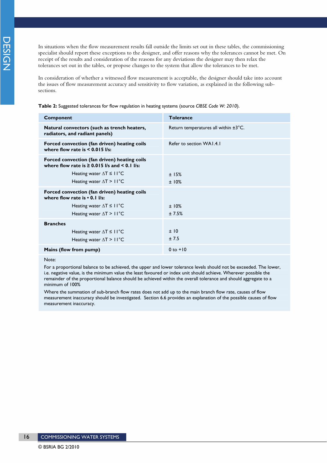
CIBSE Code W Water Distribution Systems provides tables of acceptable tolerance bands for different applications. Tables 2 and 3 indicate the tolerances required by CIBSE Code W at the time of writing.
The tolerances set out in tables 2 and 3 may be considered to be default target values. They provide a level of accuracy that should be achievable for the majority of building services installations.
16 COMMISSIONING WATER SYSTEMS
© BSRIA BG 2/2010
In situations when the flow measurement results fall outside the limits set out in these tables, the commissioning specialist should report these exceptions to the designer, and offer reasons why the tolerances cannot be met. On receipt of the results and consideration of the reasons for any deviations the designer may then relax the tolerances set out in the tables, or propose changes to the system that allow the tolerances to be met.
In consideration of whether a witnessed flow measurement is acceptable, the designer should take into account the issues of flow measurement accuracy and sensitivity to flow variation, as explained in the following sub-sections.
Table 2: Suggested tolerances for flow regulation in heating systems (source CIBSE Code W: 2010).
Component Tolerance
Natural convectors (such as trench heaters, radiators, and radiant panels)
Return temperatures all within ±3°C.
Forced convection (fan driven) heating coils where flow rate is < 0.015 l/s:
Refer to section WA1.4.1
Forced convection (fan driven) heating coils where flow rate is 0.015 l/s and < 0.1 l/s:
Heating water T 11°C
Heating water T > 11°C ± 15%
± 10%
Forced convection (fan driven) heating coils where flow rate is • 0.1 l/s:
Heating water T 11°C
Heating water T > 11°C
± 10%
± 7.5%
Branches
Heating water T 11°C
Heating water T > 11°C
± 10
± 7.5
Mains (flow from pump) 0 to +10
Note:
For a proportional balance to be achieved, the upper and lower tolerance levels should not be exceeded. The lower, i.e. negative value, is the minimum value the least favoured or index unit should achieve. Wherever possible the remainder of the proportional balance should be achieved within the overall tolerance and should aggregate to a minimum of 100%
Where the summation of sub-branch flow rates does not add up to the main branch flow rate, causes of flow measurement inaccuracy should be investigated. Section 6.6 provides an explanation of the possible causes of flow measurement inaccuracy.
COMMISSIONING WATER SYSTEMS 17
© BSRIA BG 2/2010
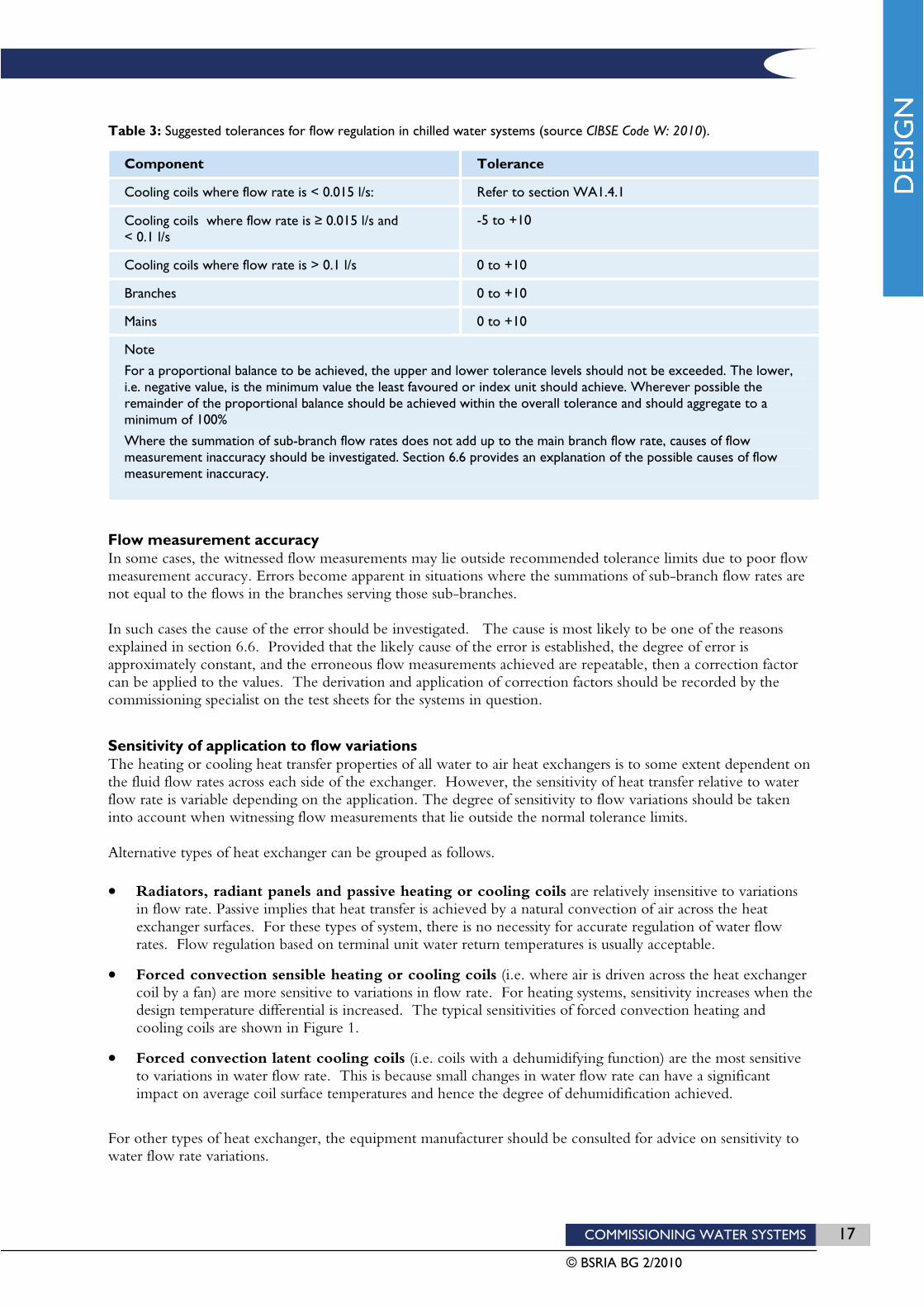
Table 3: Suggested tolerances for flow regulation in chilled water systems (source CIBSE Code W: 2010).
Component Tolerance
Cooling coils where flow rate is < 0.015 l/s: Refer to section WA1.4.1
Cooling coils where flow rate is 0.015 l/s and < 0.1 l/s
-5 to +10
Cooling coils where flow rate is > 0.1 l/s 0 to +10
Branches 0 to +10
Mains 0 to +10
Note
For a proportional balance to be achieved, the upper and lower tolerance levels should not be exceeded. The lower, i.e. negative value, is the minimum value the least favoured or index unit should achieve. Wherever possible the remainder of the proportional balance should be achieved within the overall tolerance and should aggregate to a minimum of 100%
Where the summation of sub-branch flow rates does not add up to the main branch flow rate, causes of flow measurement inaccuracy should be investigated. Section 6.6 provides an explanation of the possible causes of flow measurement inaccuracy.
Flow measurement accuracy In some cases, the witnessed flow measurements may lie outside recommended tolerance limits due to poor flow measurement accuracy. Errors become apparent in situations where the summations of sub-branch flow rates are not equal to the flows in the branches serving those sub-branches.
In such cases the cause of the error should be investigated. The cause is most likely to be one of the reasons explained in section 6.6. Provided that the likely cause of the error is established, the degree of error is approximately constant, and the erroneous flow measurements achieved are repeatable, then a correction factor can be applied to the values. The derivation and application of correction factors should be recorded by the commissioning specialist on the test sheets for the systems in question.
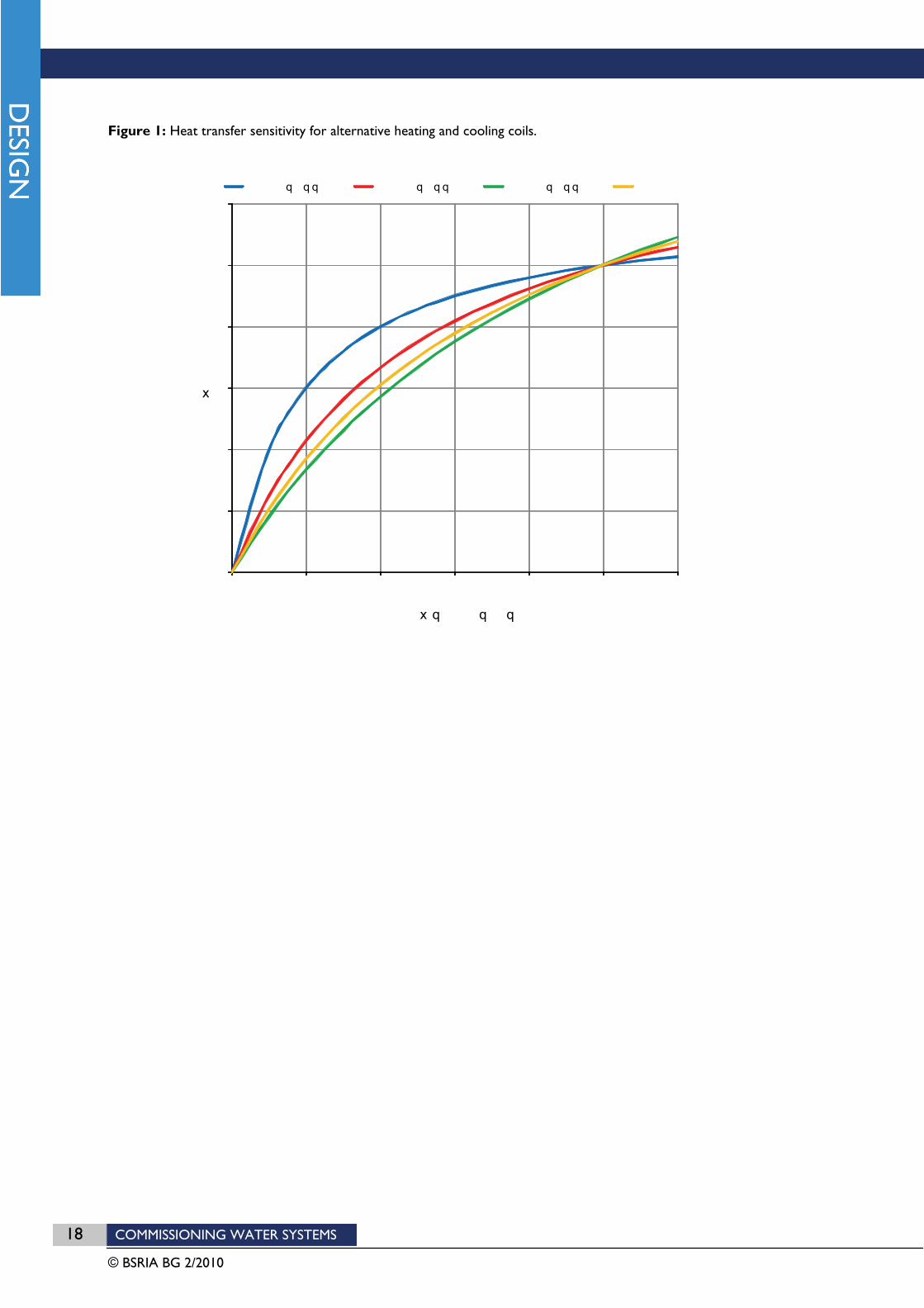
Sensitivity of application to flow variations The heating or cooling heat transfer properties of all water to air heat exchangers is to some extent dependent on the fluid flow rates across each side of the exchanger. However, the sensitivity of heat transfer relative to water flow rate is variable depending on the application. The degree of sensitivity to flow variations should be taken into account when witnessing flow measurements that lie outside the normal tolerance limits.
Alternative types of heat exchanger can be grouped as follows.
Radiators, radiant panels and passive heating or cooling coils are relatively insensitive to variations in flow rate. Passive implies that heat transfer is achieved by a natural convection of air across the heat exchanger surfaces. For these types of system, there is no necessity for accurate regulation of water flow rates. Flow regulation based on terminal unit water return temperatures is usually acceptable.
Forced convection sensible heating or cooling coils (i.e. where air is driven across the heat exchanger coil by a fan) are more sensitive to variations in flow rate. For heating systems, sensitivity increases when the design temperature differential is increased. The typical sensitivities of forced convection heating and cooling coils are shown in Figure 1.
Forced convection latent cooling coils (i.e. coils with a dehumidifying function) are the most sensitive to variations in water flow rate. This is because small changes in water flow rate can have a significant impact on average coil surface temperatures and hence the degree of dehumidification achieved.
For other types of heat exchanger, the equipment manufacturer should be consulted for advice on sensitivity to water flow rate variations.
18 COMMISSIONING WATER SYSTEMS
© BSRIA BG 2/2010
Figure 1: Heat transfer sensitivity for alternative heating and cooling coils.
%
%
COMMISSIONING WATER SYSTEMS 19
© BSRIA BG 2/2010
3 Commissioning devices A variety of pipeline devices are available to either improve system performance or facilitate commissioning. The devices that are most likely to require attention during commissioning are those providing the following functions:
flow regulation;
flow measurement;
differential pressure control.
These functions can be achieved in pipework systems by a variety of specialist valve products. It is useful to categorise these as manually operated or self-acting whereby:
a manually operated valve is one which, once set, will maintain a constant resistance under all operating conditions;
a self-acting valve is one which, when the system is set to work, will then vary its resistance automatically to suit the particular operating conditions.
It should also be noted that many of the valve types performing these functions also enable flow isolation thereby avoiding the need for separate isolating valves.
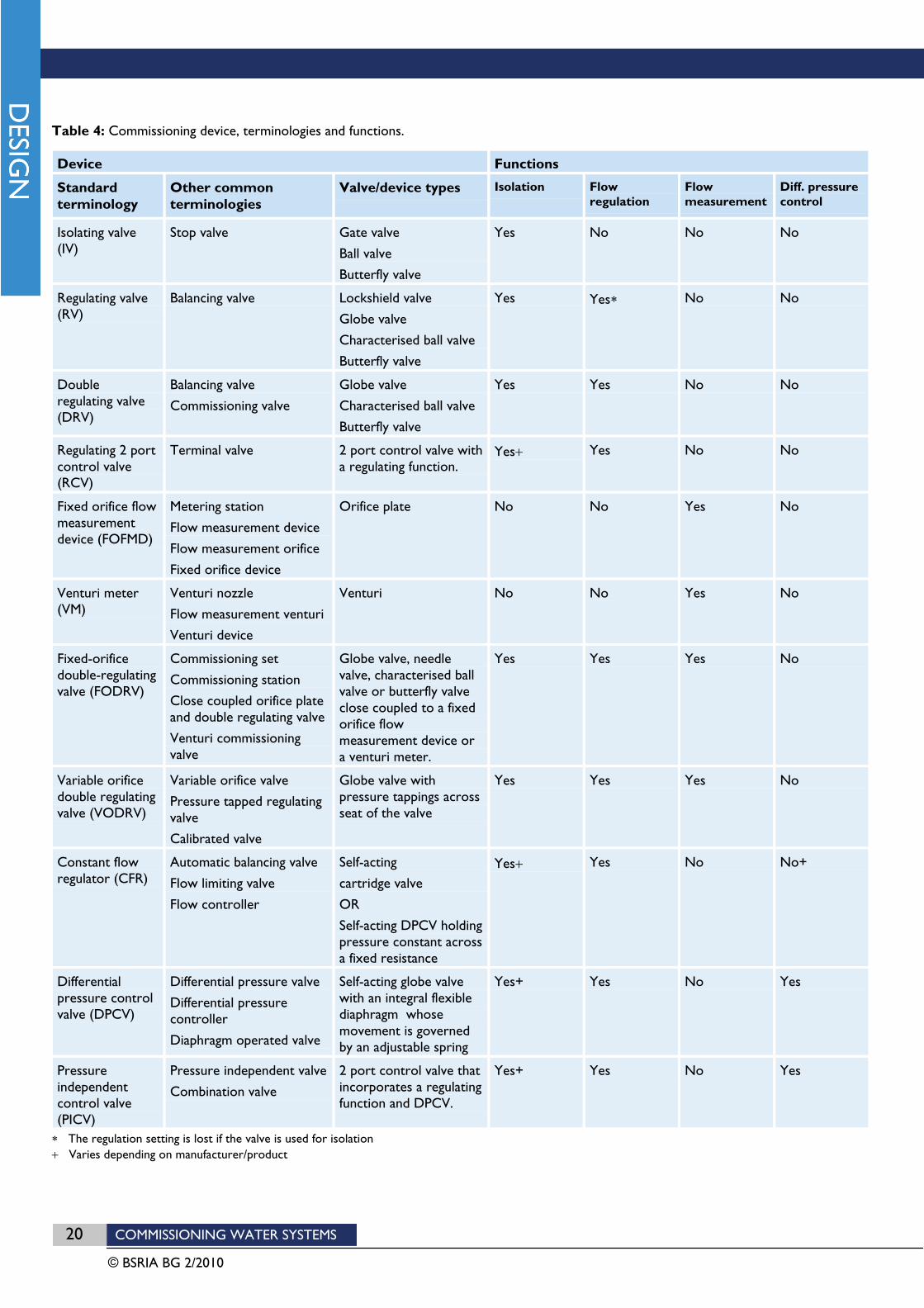
A summary of the different commissioning device types is provided in Table 4. The subsequent sections explain how they work, and how they should be selected.
20 COMMISSIONING WATER SYSTEMS
© BSRIA BG 2/2010
Table 4: Commissioning device, terminologies and functions.
Device Functions
Standard terminology
Other common terminologies
Valve/device types Isolation Flowregulation
Flowmeasurement
Diff. pressure control
Isolating valve (IV)
Stop valve Gate valve
Ball valve
Butterfly valve
Yes No No No
Regulating valve (RV)
Balancing valve Lockshield valve
Globe valve
Characterised ball valve
Butterfly valve
Yes Yes No No
Doubleregulating valve (DRV)
Balancing valve
Commissioning valve
Globe valve
Characterised ball valve
Butterfly valve
Yes Yes No No
Regulating 2 port control valve (RCV)
Terminal valve 2 port control valve with a regulating function.
Yes Yes No No
Fixed orifice flow measurementdevice (FOFMD)
Metering station
Flow measurement device
Flow measurement orifice
Fixed orifice device
Orifice plate No No Yes No
Venturi meter (VM)
Venturi nozzle
Flow measurement venturi
Venturi device
Venturi No No Yes No
Fixed-orifice double-regulatingvalve (FODRV)
Commissioning set
Commissioning station
Close coupled orifice plate and double regulating valve
Venturi commissioning valve
Globe valve, needle valve, characterised ball valve or butterfly valve close coupled to a fixed orifice flow measurement device or a venturi meter.
Yes Yes Yes No
Variable orifice double regulating valve (VODRV)
Variable orifice valve
Pressure tapped regulating valve
Calibrated valve
Globe valve with pressure tappings across seat of the valve
Yes Yes Yes No
Constant flow regulator (CFR)
Automatic balancing valve
Flow limiting valve
Flow controller
Self-acting
cartridge valve
OR
Self-acting DPCV holding pressure constant across a fixed resistance
Yes Yes No No+
Differential pressure control valve (DPCV)
Differential pressure valve
Differential pressure controller
Diaphragm operated valve
Self-acting globe valve with an integral flexible diaphragm whose movement is governed by an adjustable spring
Yes+ Yes No Yes
Pressureindependentcontrol valve (PICV)
Pressure independent valve
Combination valve
2 port control valve that incorporates a regulating function and DPCV.
Yes+ Yes No Yes
The regulation setting is lost if the valve is used for isolation Varies depending on manufacturer/product
COMMISSIONING WATER SYSTEMS 21
© BSRIA BG 2/2010
3.1 REGULATING VALVES
Regulating valves are valves that are used to add resistance in pipework circuits so as to enable regulation of system flow rates. The term “regulating valve” usually implies a manually operated valve as opposed to a self-acting valve.
To be effective for flow regulation a regulating valve should have an approximately linear characteristic (i.e. the relationship between valve closure and the reduction in flow should be approximately linear).
Valve types that are suitable for use as regulating valves include:
oblique or vertical pattern globe valves
butterfly valves
characterised ball valves
Common examples of regulating valves include lockshield valves that are used to regulate the flow rates through radiators, and screw down stop valves that are used to regulate incoming mains water flow rates. These valves enable the flow through the pipe to be regulated to suit the application, however, if the valve is subsequently used for isolation, its original setting would be lost and it would need to be re-set.
Double regulating valves A double regulating valve is a valve that can perform the double function of flow isolation and regulation. This double function is achieved by incorporating a locking mechanism in the handle of the regulating valve. This allows the valve handle to be adjusted until the required flow rate is achieved, and then locked in place. If the valve is subsequently closed for isolation purposes, on re-opening, the valve handle will only open as far as its locked position.
Double regulating valves are available as oblique angle globe valves in most sizes. At nominal pipe diameters greater than 50mm, globe valves can become expensive and butterfly valves are commonly used as an alternative.
Double regulating globe valves should comply with BS 7350: 1990 Double Regulating Globe Valves and Flow Measurement Devices for Heating and Chilled Water Systems. Other valve types should be shown to provide an equal level of regulating ability.
Figure 2 shows typical examples of double regulating globe valves. Figure 3 shows a typical double regulating butterfly valve.

COMMISSIONING WATER SYSTEMS 23
© BSRIA BG 2/2010
Regulating 2 port control valves Control valves for which the main function is to automatically vary the flow rates through terminal units during normal operation are sometimes designed to incorporate a regulating function alongside the control function. This is possible since most control valves are globe valves and have an ideal flow control characteristic.
A common solution is to allocate the first part of the travel of the valve for regulating purposes. This means that the valve can be used to manually regulate the flow to the required value. Once the flow rate is set, an actuator is fitted to the valve handle and the remaining closure of the valve is then available for flow control.
Selection advice for regulating valves As a general rule, in order to minimise the risk of noise, cavitation, or the build-up of solids between plug and seat, regulating valves should not be regulated to a setting less than 25% open. Although applicable to all types of regulating valve, this rule is most commonly applied to double regulating valves since it is usually easy to determine the 25% open position (i.e. setting 1 on a handle with 4 turns from open to closed).
Therefore, each double regulating valve must be selected such that at its 25% open position, the pressure differential generated across the valve (due to valve closure) is greater than the required residual pressure (where residual pressure is equal to the design pressure loss around the index circuit minus the design pressure loss for the particular circuit in which the valve is installed). If the residual pressure has not been calculated, a value of at least 5kPa should be assumed.
To comply with the above criteria, regulating valves will not always be the same size as the adjoining pipework. It may be necessary to install a regulating valve with a smaller nominal diameter than the adjoining pipe in order to generate a sufficient pressure loss at its 25% open position. Hence, valves must always be selected independently based on the anticipated design flow rate and residual pressure value. Valve manufacturers provide selection software that allows valves to be selected based on these parameters.
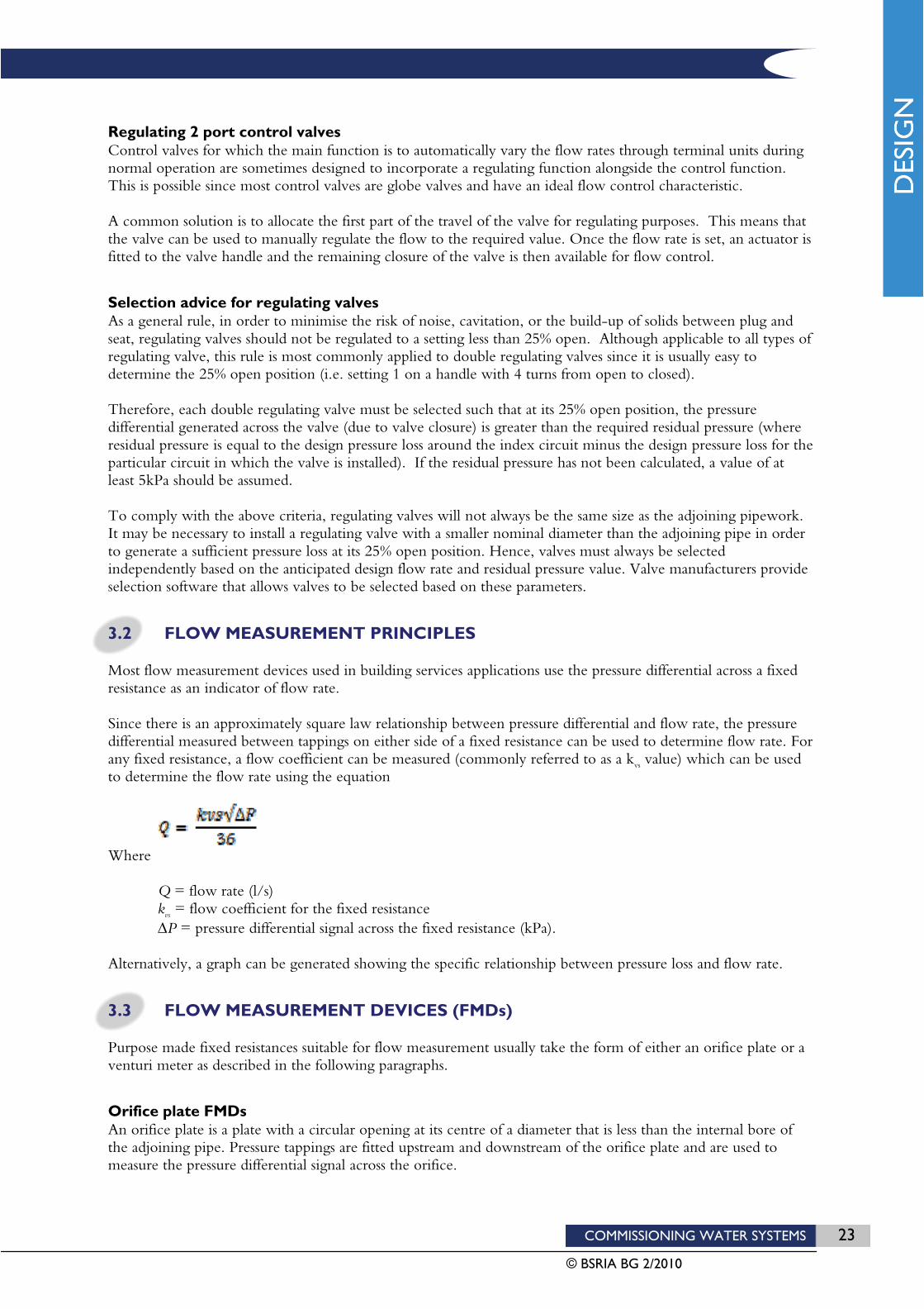
3.2 FLOW MEASUREMENT PRINCIPLES
Most flow measurement devices used in building services applications use the pressure differential across a fixed resistance as an indicator of flow rate.
Since there is an approximately square law relationship between pressure differential and flow rate, the pressure differential measured between tappings on either side of a fixed resistance can be used to determine flow rate. For any fixed resistance, a flow coefficient can be measured (commonly referred to as a kvs value) which can be used to determine the flow rate using the equation
Where
Q = flow rate (l/s) kvs = flow coefficient for the fixed resistance
P = pressure differential signal across the fixed resistance (kPa).
Alternatively, a graph can be generated showing the specific relationship between pressure loss and flow rate.
3.3 FLOW MEASUREMENT DEVICES (FMDs)
Purpose made fixed resistances suitable for flow measurement usually take the form of either an orifice plate or a venturi meter as described in the following paragraphs.
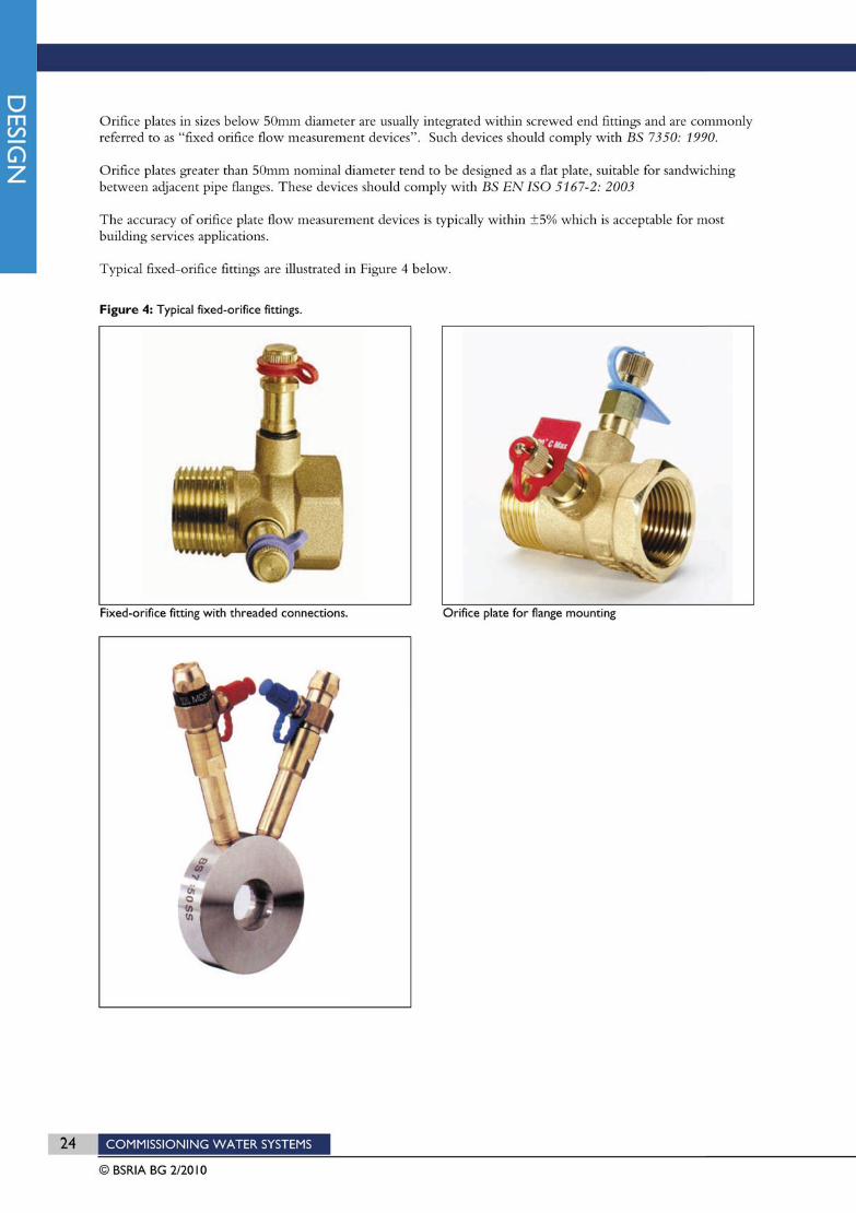
Orifice plate FMDs An orifice plate is a plate with a circular opening at its centre of a diameter that is less than the internal bore of the adjoining pipe. Pressure tappings are fitted upstream and downstream of the orifice plate and are used to measure the pressure differential signal across the orifice.

COMMISSIONING WATER SYSTEMS 25
© BSRIA BG 2/2010
Venturi meter FMD A venturi meter uses the pressure differential across a concentric pipework constriction as an indicator of flow rate. The inside diameter of the venturi reduces gradually until it reaches the narrowest point (the throat) and then opens gradually back to the adjoining pipe diameter. This profile means that the meter is able to accelerate and then decelerate the fluid velocity generating a measureable pressure loss signal but with a minimum overall pressure loss. Pressure tappings at the throat (maximum velocity) and at the maximum diameter (minimum velocity), enable the pressure differential signal to be recorded for conversion to a flow rate using the flow coefficient (kvs factor) for the device provided by the manufacturer.
Due to the gradual constriction of the pipe, venturi meters are the most accurate type of fixed resistance flow measurement device and can usually achieve flow measurement accuracies within ±3%. They also have a lower resistance than orifice type devices.
Venturi meters should comply with BS EN ISO 5167(38,39) or be demonstrated to prove an equivalent degree of flow measurement accuracy.
Selection advice for FMDs FMDs must be selected such that the pressure differential signal generated at the design flow rate is at least 1kPa. This value is considered to be the minimum required to provide an accurate indication of flow rate. Manufacturers of FMDs typically indicate minimum measureable flow rates for their devices that correspond with a 1kPa signal.
It should be noted that the manufacturer’s minimum measureable flow rates for each device size may not match the minimum flow rates that might be specified in pipes of an equivalent size. It may therefore be necessary to install FMDs with a smaller nominal diameter than the adjoining pipes in order to generate a signal of more than 1kPa.
Therefore, FMDs must always be selected independently based on the anticipated design flow rate that is to be measured rather than the connecting pipe size. Device manufacturers provide selection software that enable devices to be sized based on specified flow rates.
In order to achieve accurate flow measurements within the manufacturer’s stated limits, care must be taken to install the device in a location that guarantees stable and uniform flow at its entry. Further advice is provided in section 4.5.
3.4 IMPROVISED FLOW MEASUREMENT
In situations where it is not possible to install a purpose made flow measurement device, flow rate may usually be calculated to an acceptable accuracy using one of the following techniques.
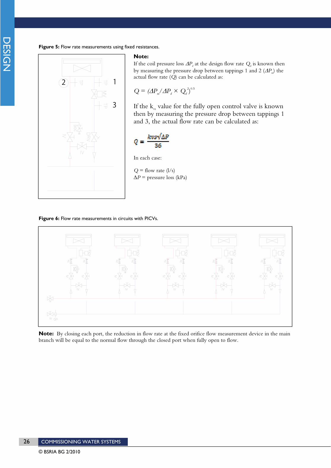
The installation of pressure tappings across a fixed resistance such as a terminal unit or a control valve. Figure 5 illustrates the principle. If an accurate pressure loss value for the fixed resistance can be obtained from the manufacturer, then the measured pressure differential across it can be used to determine flow rate. Control valve manufacturers in particular, are able to provide accurate kvs values for control valves.
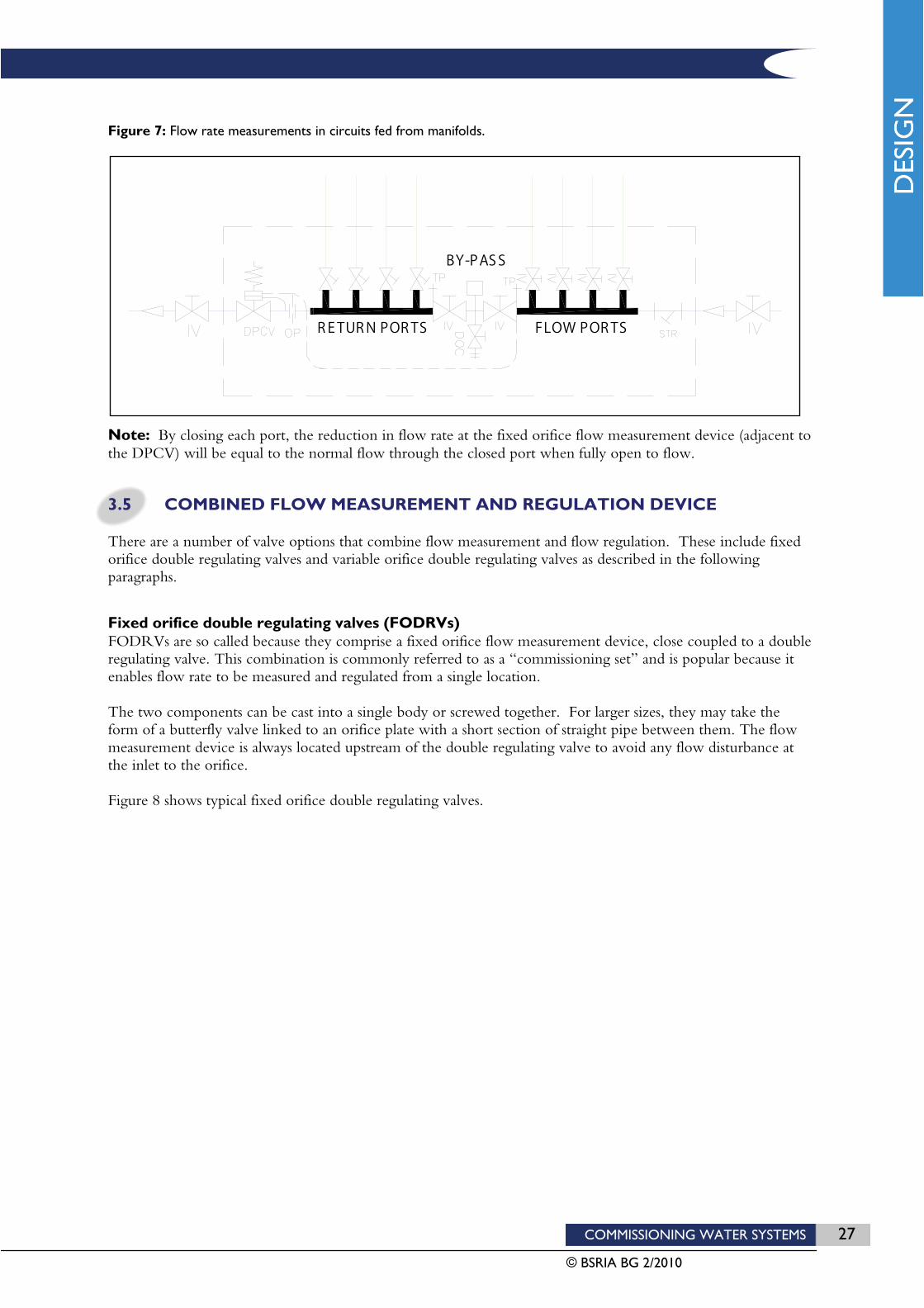
Adopting a “subtraction method” of flow measurement whereby the flow rate through a particular terminal branch is estimated by measuring the reduction in flow rate that occurs through an upstream flow measurement device when the terminal branch is isolated. This solution works best in circuits serving terminal branches with pressure independent control valves or for terminal circuits fed from a manifold arrangements (as illustrated in Figure 6 and Figure 7) since in both cases the closure of any individual terminal branch should not affect the flow rates in other terminal branches.
The measurement of pressure differential across the pump, and its operating power consumption. These values can be plotted on the manufacturer’s pump and power curves and the corresponding flow rate value read from the same graph.
26 COMMISSIONING WATER SYSTEMS
© BSRIA BG 2/2010
13
2
Figure 5: Flow rate measurements using fixed resistances.
Note:If the coil pressure loss Pd at the design flow rate Qd is known then by measuring the pressure drop between tappings 1 and 2 ( Pm) the actual flow rate (Q) can be calculated as:
Q = ( Pm/ Pd × Qd
2)0.5
If the kvs value for the fully open control valve is known then by measuring the pressure drop between tappings 1 and 3, the actual flow rate can be calculated as:
In each case:
Q = flow rate (l/s) P = pressure loss (kPa)
Figure 6: Flow rate measurements in circuits with PICVs.
Note: By closing each port, the reduction in flow rate at the fixed orifice flow measurement device in the main branch will be equal to the normal flow through the closed port when fully open to flow.
COMMISSIONING WATER SYSTEMS 27
© BSRIA BG 2/2010
Figure 7: Flow rate measurements in circuits fed from manifolds.
Note: By closing each port, the reduction in flow rate at the fixed orifice flow measurement device (adjacent to the DPCV) will be equal to the normal flow through the closed port when fully open to flow.
3.5 COMBINED FLOW MEASUREMENT AND REGULATION DEVICE
There are a number of valve options that combine flow measurement and flow regulation. These include fixed orifice double regulating valves and variable orifice double regulating valves as described in the following paragraphs.
Fixed orifice double regulating valves (FODRVs) FODRVs are so called because they comprise a fixed orifice flow measurement device, close coupled to a double regulating valve. This combination is commonly referred to as a “commissioning set” and is popular because it enables flow rate to be measured and regulated from a single location.
The two components can be cast into a single body or screwed together. For larger sizes, they may take the form of a butterfly valve linked to an orifice plate with a short section of straight pipe between them. The flow measurement device is always located upstream of the double regulating valve to avoid any flow disturbance at the inlet to the orifice.
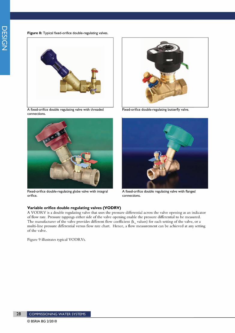
Figure 8 shows typical fixed orifice double regulating valves.
F L O W P O R T SR E T U R N P O R T S
B Y - P A S S

COMMISSIONING WATER SYSTEMS 29
© BSRIA BG 2/2010
Figure 9: Typical variable orifice double regulating valves.
Variable-orifice double-regulating valve with threaded connections.
Variable-orifice double-regulating valve with flange connections..
Selection advice for FODRVs and VODRVs For FODRVs, the rules governing the application and sizing of regulating valves and flow measurement devices (as explained in the preceding sections) are equally applicable when they are coupled together. For the reasons previously explained, it is possible that FODRVs will need to be smaller in size that the adjoining pipework. However, it is unusual for the double regulating valve to have a different nominal diameter from its close coupled flow measurement device.
The accuracy of flow measurements taken using a VODRV is typically within ±5% when the valve is in its fully open position, but can deteriorate to ±15% when the valve is at its 25% open position. The accuracy can further deteriorate if the valve becomes blocked. In order to avoid commissioning problems, the use of VODRVs should be limited to situations where the valves will not need to be throttled below 50% open.
3.6 CONSTANT FLOW REGULATOR (CFR)
A CFR is any self-acting device that operates to hold the flow rate through the branch in which it is installed constant regardless of pressure and flow rate changes in surrounding branches. If used in conjunction with a 2 port control valve they are more commonly referred to as “flow limiting valves” since they limit the flow rate to the set value but do not prevent the flow from reducing as the control valve closes.
The simplest type of constant flow regulator consists of a spring loaded stainless steel cartridge that sits inside a casing. Water flows through the middle of the cartridge and out through profiled holes in the sides. The water pressure pushing at the inlet to the cartridge causes the front part of the cartridge to compress the spring and move into the body. This has the effect of reducing the area of the holes thereby increasing the resistance to flow. The consequence is that under varying pressure conditions, flow is held constant.
A more sophisticated type of a constant flow regulator would be a differential pressure control valve (as described in section 3.7) that acts to maintain a constant pressure differential across a fixed resistance such as an orifice plate.
All types of constant flow regulator are self-acting due to an integral spring that compresses or extends depending on changes in system pressure. In order to work effectively, the spring must never be fully extended nor fully compressed, since in either of these two conditions, the spring will cease to have any effect and the valve will behave as a fixed resistance. Hence, constant flow regulators only work within a range of differential pressures, as stated by the manufacturer. They usually have pressure tappings built into the valve body so that the commissioning specialist can check that the pressure differential across the valve is within its specified range.

30 COMMISSIONING WATER SYSTEMS
© BSRIA BG 2/2010
Figure 10: Cartridge type constant flow regulator.
Selection advice for constant flow regulators CFRs can be selected based on flow rate alone. If pipes are sized within normal design parameters, the selection of constant flow regulators should result in a valve size that is the same as the adjoining pipe size, although this cannot be guaranteed.
3.7 DIFFERENTIAL PRESSURE CONTROL VALVES (DPCVs)
DPCVs are self-acting valves that act in response to changes in pressure differential between their inlet port and a position somewhere upstream in the pipework system. These two pressures are transmitted to either side of a flexible diaphragm inside the valve via small capillary tubes. As the diaphragm flexes in response to the changing pressure differential, it causes the valve plug to move thereby varying the opening through the valve. The effect is to maintain a constant pressure differential between the inlet to the valve and the upstream point to which the capillary tube attaches. The pressure setting can be varied, but once set, the action of the valve will hold it constant regardless of changes in the resistance of the circuit and regardless of changes in the available pump pressure.
DPCVs are commonly used to help protect, and make it easier to select, 2 port control valves (including thermostatic regulating valves). These control valve are used in variable flow systems to control the heating or cooling outputs of terminal units by throttling the flow of water when the required space temperature is achieved. The valves may begin to generate noise if required to close against excessive pressures. Furthermore their ability to accurately modulate heating or cooling output may be compromised. DPCVs installed somewhere in the return pipes downstream of 2 port control vaves will help to minimise the pressure differentials against which 2 port control valves must close.
As for constant flow regulators, due to the action of the integral spring, DPCVs only work within a range of differential pressures, as stated by the manufacturer. Pressure tappings should be installed across the valve so that the commissioning specialist can check that the pressure differential across the valve is within its specified range.
There are two main types of DPCV in use. The most common is the adjustable type which incorporates some sort of adjustment device that enables the controlled differential pressure setting of the valve to be varied. In practice, the commissioning specialist is more often given a design value for flow rate rather than pressure differential. Hence, the valve would be adjusted until the design flow rate is achieved.
Less common is the fixed differential pressure type DPCV. This type of DPCV comes factory set to maintain a certain fixed differential pressure between two points in the system. The valve differential pressure setting cannot be adjusted, other than by opening the head of the valve and changing the spring. Hence, since the pressure differential is set at a specific value, flow rates have to be achieved by the closure of downstream regulating valves.
Typical DPCVs are shown in Figure 11.

COMMISSIONING WATER SYSTEMS 31
© BSRIA BG 2/2010
Figure 11: Differential pressure control valves.
Selection advice for DPCVs Differential pressure control valves must be sized based on the downstream pressure differential that they are required to hold constant, and the upstream pressure differential that they may be required to control against.
The pressure differential to be held constant by the action of the valve will be the pressure loss in the downstream branch or circuit where the valve is to be installed. The design pressure losses for all downstream components should be summated and the valve sized on this value.
The maximum upstream pressure differential that the valve might be exposed to is usually the full pump pressure. Therefore the valve selected must be capable of closing against a maximum pressure differential that is greater than or equal to the pump pressure.
Because DPCVs rely on the operation of a metal spring to respond to changes in pressure differential they will not always control the set downstream pressure differential constant under all conditions. This drift is due to the hysteresis effect experienced by all springs, which means that the expansion and contraction of the spring will not be uniform. The drift experienced is known as the valve’s “proportional band” and can be measured by the manufacturer. Designers should therefore satisfy themselves that for the range of operating pressures in their system, the proposed valves will maintain differential pressures constant within an acceptable range. Valve manufacturers should be able to provide test data to enable this check to be made.
In order for the valve to operate effectively, the controlling spring must remain within the central region of its compression during normal operation. Therefore, the manufacturer’s stated minimum pressure differential across the valve itself must be included in the calculation of pump pressure.
32 COMMISSIONING WATER SYSTEMS
© BSRIA BG 2/2010
3.8 PRESSURE INDEPENDENT CONTROL VALVES (PICVs)
Pressure independent control valves, sometimes referred to as “combination valves”, combine the functions of a double regulating valve, differential pressure control valve and 2 port control valve within a single valve body.
Because the integral differential pressure control valve holds the pressure differential constant across the integral 2 port control valve, the result is that whenever the control valve is fully open, the flow rate through the valve always returns to its set value (since a constant pressure differential across a fixed resistance results in a constant flow rate).
The opening through the 2 port control valve can be varied manually, and can therefore be used to regulate the flow rate through the valve to the required design value. The flow rate can be set using an integral mechanism within the valve. Once set, the valve will perform the function of a constant flow regulator whenever the 2 port control valve is fully open. Only when the control valve begins to close will the flow rate change from its set value.
Because PICVs rely on the operation of a spring to respond to changes in pressure differential (and all springs exhibit a hysteresis effect), they will not always control the flow rate constant under varying differential pressure conditions. This drift is known as the valve’s “proportional band”. Specifiers should therefore satisfy themselves that for the range of operating pressures in their system, the proposed valves will maintain flow rates within an acceptable range. Valve manufacturers should be able to provide test data to enable this check to be made.
Selection advice for PICVs Each PICV must be selected such that the design flow rate for the terminal unit it is to serve is not less than the minimum setting of the valve. This consideration may limit the applicability of some PICVs in circuits feeding terminal units with ultra low flow rates (as desfined in section 2.7.
The maximum upstream pressure differential that the valve might be exposed to is usually the full pump pressure. Therefore the valve selected must be capable of closing against a maximum pressure differential that is greater than the pump pressure.
PICVs vary in design and performance. In order to provide effective modulating control, valves should be able to demonstrate an approximately equal percentage control characteristic (rather than on/off or linear), and must be sized such that the design flow rate is within the setting range of the valve.
Typical PICVs are shown in Figure 12.


34 COMMISSIONING WATER SYSTEMS
© BSRIA BG 2/2010
3.9 GUIDELINES FOR LOCATING COMMISSIONING DEVICES
The main rules governing the application of pipeline devices with a commissioning function are summarised in Table 4. More detailed advice on system design is provided in CIBSE Knowledge Series Guide KS7 Variable Flow Pipework Systems.
In general, all control or commissioning devices should be installed in the return pipework as opposed to the flow pipework. The reason for this is mainly convention since it assists uniformity in circuit layouts. There is seldom any technical necessity install commissioning devices in return pipes although if in doubt, the device manufacturer should be consulted.
Table 5: Valve applications.
Valve type Application notes
Lockshield radiator valves
SUITABLE for radiator, radiant panel, natural convector and underfloor heating circuit connections.
Double regulating valve (DRV)
SUITABLE for system branches, sub-branches and terminal branches where manual balancing of flow rates is required (usually installed as part of a FODRV).
USUALLY REQUIRED on 3 port control valve by-passes in order to balance the by-pass. (Not required if the circuit flow is held constant by a CFR).
NOT USUALLY REQUIRED on the same branches as DPCVs, CFRs, or PICVs, nor on any of the branches feeding to sub-branches containing these devices.
NOT REQUIRED on the main return to the pump, unless the pump is a constant speed pump. For variable speed pumps, pump speed should be set using the pump speed controller.
Fixed orifice flow measurement devices (FOFMDs) or venturi meters
REQUIRED in branches, sub-branches and terminal branches where manual proportional balancing is required (usually installed as part of a FODRV).
REQUIRED in branches with DPCVs to enable the DPCV to be set.
OPTIONAL in the same branches as CFRs or PICVs as a means of checking whether the set flow rate is being maintained constant.
REQUIRED in main branches feeding to sub-branches with CFRs or PICVs as a means of checking the summated flows through the downstream CFRs or PICVs.
REQUIRED in main return pipes to the pump as a means of checking and setting the pump flow rate.
Fixed orifice double regulating valves (FODRV) “commissioning sets”
RECOMMENDED in all branches and sub-branches of a system where manual proportional balancing of flow rates is required.
NOT USUALLY REQUIRED in the same branches as DPCVs (unless as a “partner valve” where its pressure tapping is used to connect the DPCV capillary tube). Nor are they required in branches feeding to sub-branches with DPCVs.
NOT REQUIRED in systems where terminal unit flow rates are maintained constant by CFRs or PICVs.
Differential pressure control valves (DPCVs)
REQUIRED in main branches feeding to sub-branches containing 2 port control valves where the potential pressure differential across the sub-branches could be excessive for the 2 port valves to close against, or could result in poor control valve authority.
Constant flow regulators (CFRs)
SUITABLE as an alternative to regulating valves on terminal branches in constant flow systems.
NOT ADVISABLE in series with modulating 2 port control valves, but fine in series with on/off 2 port control valves.
NOT USUALLY REQUIRED on branches upstream of the terminal unit branches.
Pressure independent control valves (PICVs)
RECOMMENDED on terminal unit branches as an alternative to separate control valves, regulating valves and differential pressure control valves.
MAY NOT BE SUITABLE for ultra low flow terminal units.
NOT REQUIRED on branches upstream of the terminal unit branches.

COMMISSIONING WATER SYSTEMS 35
© BSRIA BG 2/2010
4 The installation of commissionable systems
The installer’s objective is to provide a pipework installation that meets the specified requirements. To achieve this, properly managed resources must be allocated to the process of constructing a commissionable system. The tendering or appointed installer must carefully study the enquiry and contract documents to determine the project requirements.
Guidance on the management of the commissioning process is provided in:
CIBSE Code M, Commissioning Management.
BSRIA Guide BG6/2009, A Design Framework for Building Services
BSRIA Guide BG1/2009, Building Services Job Book
BSRIA Guide BG8/2009, Model Commissioning Plan
4.1 ORGANISATION AND PLANNING
Where the installer is responsible for commissioning, the commissioning specialist should be selected and instructed at the earliest possible stage to ensure that expertise is available in the planning and programming of the commissioning tasks.
Together, the commissioning specialist and installer should undertake the following tasks.
Establish effective lines of communication between the commissioning specialist and other parties involved.
Produce a set of working drawings that show the detailed provisions for incorporating the commissioning facilities.
Review the contract documents to determine the requirements for commissioning, seeking clarification where necessary.
Produce a realistic programme which incorporates the commissioning activities, phased with the installation programme.
Regularly review the programme during installation to establish the effect of modifications and delays on the planned static completion and power-on dates and any other dates critical to the commissioning activities.
Acquire all the information specified in section 2.1 from the designer.
Obtain the latest information for all items supplied by equipment suppliers and manufacturers.
Check manufacturer’s literature for any installation requirements additional to those specified.
Progressively record as-installed information on at least two sets of installation drawings: one clean set to facilitate the production of the record drawings and operating/maintenance documentation, and one site set for use by the commissioning specialist.
Establish systematic site control procedures to assist the progressive monitoring of the standard of the pipework installation practices maintained on site.
Give input to co-ordinated ceiling plans illustrating access panel requirements.
Establish an equipment and materials procurement procedure which incorporates an effective means of checking each and every delivered item against specified requirements.
Retain all documents and literature provided with each delivered item of equipment for use by the commissioning specialist (and for inclusion in the operating and maintenance manuals).

36 COMMISSIONING WATER SYSTEMS
© BSRIA BG 2/2010
4.2 INSTALLATION ISSUES AFFECTING COMMISSIONAIBILITY
Pipework installation procedures have a considerable influence upon flow measurement accuracy and the eventual ease with which a water system can be commissioned. The installer is responsible for ensuring that operators and supervisors are trained and supplied with appropriate work instructions to enable them to meet the installation requirements for commissioning the systems.
The following sections explain the main issues that need to be considered during installation.
4.3 HOUSEKEEPING
The following practices should be encouraged.
Materials and components should be delivered to site in packaging supplied by the manufacturer or stockist. Packaging should not be removed until the equipment is ready for installation. If it is necessary to remove the packaging for the purpose of inspection, it should be replaced and/or made good immediately afterwards.
To prevent contamination from building debris, all delivered pipes should be racked and all valves, strainers and fittings should be stored on shelving above the ground with all open ends capped. Special care should be taken to protect items temporarily stored at the workstation immediately prior to installation.
Temporary protection devices should be removed from equipment immediately before its installation and prior to making the final connections.
All care should be taken to avoid the ingress of site debris or jointing materials to the pipework during installation.
Incomplete pipework should be adequately protected and all open ends temporarily blanked off.
4.4 WORKMANSHIP
The measurement accuracy of flow measurement devices is dependent upon good installation workmanship. The following points are of particular importance.
Pipes and components should be inspected immediately prior to installation and any contaminants removed.
Avoid the intrusion of jointing material or weld splatter into the water flow as this may create blockages at valves.
All cut pipe ends, and particularly those immediately upstream of a flow measurement device, should be completely de-burred and any distortions in bore diameter due to roller cutting rectified.
Compression connections should be tightened to the correct level so as not to distort the pipe bore.
4.5 INSTALLATION OF COMMISSIONING DEVICES
Well detailed pipework arrangements and configurations around commissioning devices can have a substantial influence upon the commissionability of the system.
The following bullet points cover the main recommendations.
Care should always be taken to ensure that flow measurement and regulating devices are installed correctly with respect to water flow direction (generally, an arrow indicating flow direction will be stamped on the body of the device). A flow measurement device must always be positioned upstream of associated regulating valves when the two are installed together.

COMMISSIONING WATER SYSTEMS 37
© BSRIA BG 2/2010
In order to achieve the manufacturer’s stated flow measurement accuracy, flow measurement devices must be located on a straight length of pipe with minimum lengths of straight pipe upstream and downstream of the device as recommended by the device manufacturer. Typical minimum requirements for straight lengths around flow measurement devices are indicated in Table 5.
The specified grade of pipe material should always be installed upstream and downstream of a flow measurement device, with a nominal diameter equivalent to that of the flow measurement device. Manufacturers’ performance charts are generally based on BS EN 10255(40) medium grade steel pipe. If the connection to the flow measurement device is to be made in a different type of pipe, this should be notified to the commissioning specialist so that a correction factor can be issued if necessary.
Generally, pipe adaptor connections (from plastic, copper or thin-walled steel pipes) to screwed end orifice type flow measurement devices should be avoided. This is because these types of fitting can cause a distorted flow pattern onto the device and a resulting flow measurement inaccuracy.
Table 6: Minimum straight lengths recommended upstream and downstream of flow measurement devices.
Type Upstream diameters
Downstreamdiameters
Fixed orifice and variable orifice double regulating valves 5 2
Orifice plates installed alone or close coupled to full bore isolating valves 10 5
Venturi meters As recommended by manufacturer
4.6 ACCESSIBILITY
Adequate space should be allowed to permit access for commissioning and maintenance. Space can be very limited in suspended ceilings where services branch off from vertical risers. These are often the very locations where flow measurement devices and regulating valves are required. Attention should be given during the detailed design stage to ensure that service ducts and architectural features, such as ceilings, will be compatible with the degree of accessibility required.
Access to flow measurement devices and regulating valves should be a prime consideration during detailed design and co-ordination. In particular:
flow measurement devices should be located such that their pressure tappings are easily accessible, and pointing upwards so that they do not collect debris;
at least 200mm clearance from all pressure test points must be allowed to enable the manometer tubes to be connected without kinking and for the insertion of temperature probes;
double regulating valves must be located such that the valve setting is visible and the locking mechanism is accessible;
the flow measurement device and its associated regulating valve should be positioned as close together as possible (ideally in a close coupled set);
the thickness of pipework and ductwork insulation, and the support and bracketing arrangements, must be anticipated;
the positions of access panels in false ceilings, must be properly co-ordinated with flow measurement device and regulating valve positions.
HMSO, Defence Works Functional Standard, Design and Maintenance Guide 08 Space Requirements for Plant Access, Operation and Maintenance provides reference information for detailed design and co-ordination exercises.
BSRIA Guides .... (To be advised) Space allowances ... also provides reference information for detailed design and co-ordination exercises.
Space for access to key components is a fundamental requirement of a commissionable system.
38 COMMISSIONING WATER SYSTEMS
© BSRIA BG 2/2010
4.7 DRAINING PROVISIONS
It is important to provide the necessary facilities for draining systems quickly and conveniently. Drain points should be provided at:
system low points
all isolatable plant items.
To facilitate flushing, cleaning and maintenance, consideration should also be given to the locations and sizes of drains required to facilitate the flushing and chemical cleaning of the system (see BSRIA Application Guide, AG 1/2001.1: Pre-Commission Cleaning of Pipework Systems)
4.8 VENTING
Air trapped within a pipework system can cause non-repeatability of flow measurements i.e. over a period of time the flow rate may actually reduce from its previously set value.
Sufficient air relief valves (manual and automatic) must be installed to minimise this problem, and venting must be carried out in an organised way to ensure thorough and effective release of air. Advice on the location of air vents is provided in section 2.9.
Vents and drains should be provided in accordance with the details provided in BSRIA Application Guide, AG 1/2001.1: Pre-Commission Cleaning of Pipework System.
Initial system fill The system should be filled with water (treated, where specified) in accordance with an agreed method statement, prepared by the installing contractor. All filling procedures must comply with HVCA TR/6 SitePressure Testing of Pipewor.
Filling shall also comply with the requirements of the Water Supply (Water Fittings) Regulations 1999 for the prevention of backflow. This usually requires a break tank with a suitable air gap for indirect filling or a double check valve for direct filling.
To ensure effective venting:
ensure all isolating valves in the system to be vented are fully open and automatic vents are not capped or isolated;
fill slowly from the bottom upward thus forcing the air to high points for venting to atmosphere;
check valves and air vents before and during filling to avoid airlocks or spillage, particularly where the fill water is treated.
ensure that the working pressure of the system (or its sub-components) are not exceeded when filling from a high pressure source.
When the whole system is filled, disconnect the filling source, open the permanent supply connections and adjust the feed tank water levels.
Safety warning: do not attempt to fill the system via a pressurisation set. A pressurisation set should only be used for final system top-up and pressurisation. A quick-fill by-pass should be provided where appropriate to fill the system.
Further venting may be required after the initial operation of the pumps.
COMMISSIONING WATER SYSTEMS 39
© BSRIA BG 2/2010
Venting after pre-commission cleaning Following water treatment, a final fill and venting of the system should be undertaken following the same procedure as for the initial system fill.
Note that the venting process is critical to commissioning. Systems with entrained air or static air pockets may suffer poor repeatability of flow measurements rendering them uncommissionable.
Vent the system in following the same approach as for the initial fill. Only when the system has been fully vented at all vent locations should the system pumps be switched on. Pumps should be allowed to circulate water for a period of at least 1 hour before being switched off and venting repeated.
Methods for removing entrained air and static air pockets from the system include:
running of pumps (to circulate air towards vent positions) followed by re-venting of the system. It may be necessary to repeat this a number of times.
applying heat to the system to encourage dissolved air bubbles to come out of solution.
the installation of de-aerators on a permanent or temporary basis, as described in section 2.10.
Whichever method is selected, adequate time should be allowed for the process to be successful.
4.9 INSTALLATION INSPECTIONS
During the course of the works, the installer should progressively and systematically monitor the correctness and quality of the installation, and ensure that the good installation practices outlined in sections 4.3-4.5 have been properly implemented. The installer should also ensure that any remedial work has been completed, and that the works comply with the specified requirements.
A regular planned system of continuous inspections will:
reduce the build-up of the numbers of defects to be rectified prior to commissioning;
prevent defective work from being temporarily hidden, only to surface again during the commissioning period;
help to maintain a consistently high standard of workmanship to the end of the contract.
The methodical use of pro-forma sheets to register conformance to requirements and to monitor the progress of remedial action will result in a substantially smoother start to the commissioning process. An example pro-forma, a Continuous Inspection Checklist, is incorporated in section 8
As part of the installation checks, the installer may wish to start up pump motors briefly in order to check the wiring and control panel. If this is the case, the contractual implications of responsibility should be clearly laid down beforehand.
When the pipework and all the major components of a system have been installed, a final installation inspection should be formally undertaken to verify that the system is complete, and that preparations for the commissioning can start. Two example pro-formas to aid this procedure, the Final Installation Checklist (mechanical and electrical), are included in section 8.

40 COMMISSIONING WATER SYSTEMS
© BSRIA BG 2/2010
4.10 PREPARATION FOR COMMISSIONING
To be ready for commissioning, an installation must be:
seen to have been installed in accordance with the specification, in that the final installation inspections have been completed together with all outstanding remedial works
successfully pressure-tested in accordance with the specification and/or in accordance with HVCA TR/6 Site Pressure Testing of Pipework, published by the HVCA
flushed and cleaned in accordance with the specification and/or BSRIA Application Guide, AG 1/2001.1: Pre-Commission Cleaning of Pipework Systems
filled with water, treated as specified and vented
clean, with the spaces in the immediate vicinity of all system equipment and components requiring safe access for commissioning made free of all obstructions
safe and ready to set to work.
An installation progressed to this state of readiness for commissioning is said to have reached static completion.

COMMISSIONING WATER SYSTEMS 41
© BSRIA BG 2/2010
5 Site test instruments A great deal of time can be wasted by using the wrong kind of instrument or by trying to manage with too few instruments. In this section guidance is given on the suitability of instruments for commissioning.
Although manufacturers’ detailed instructions must always be observed, the following instructions will generally apply to all instruments used to commission systems.
Select an instrument which has an operating range greater than the maximum expected reading (if the approximate value of a particular reading is unknown, the selected instrument should be set initially to its maximum range).
Read the operating instructions before using the instrument.
Visually inspect the instrument to see that it is undamaged.
Check that the instrument has a calibration certificate which is not more than 12 months old.
Record the reading on the relevant pro forma together with the range setting and the information which may be needed to correct or interpret the results.
5.1 ROTATIONAL SPEED MEASUREMENT
Mechanical tachometers are generally used to measure rotational speeds where the shaft of the fan or motor is accessible. Provision should be made for the insertion of the tachometer spindle through an access aperture in the guard, as measurements must never be made on an unguarded drive.
Where it is not possible to use a mechanical tachometer, indirect methods using instruments such as the optical tachometer or stroboscope can be employed.
Mechanical tachometer There are two basic types of mechanical tachometer; one gives a direct reading of speed (rev/min) and the other reads the number of revolutions.
Optical tachometer This instrument projects a narrow beam of light toward the rotating shaft or pulley on which has been fixed a strip of reflecting tape. The reflected light pulses from the tape are measured as frequency (rev/min) by the meter. To be effective, the meter must be held in close proximity to the shaft or pulley.
Inductive tachometer The inductive style tachometer can often be used where both the mechanical and optical instruments are not suitable. It uses an inductive probe to count events above rotating metal objects. Typical applications include shafts with slots or toothed gears where no reflection marks can be fixed.
Stroboscope The stroboscope is a source of variable frequency light pulses and its technique is to match the source pulse frequency to the rotational speed.
A chalk mark (or similar) is made on the pulley and the stroboscope is adjusted until the mark appears stationary. It is, however, possible to obtain a stationary image with a sub-multiple (50%, 25% and 33%) of the actual shaft speed and such errors of harmonics need to be eliminated to assess the correct speed. A convenient method is to start at high speeds where multiple images are obtained. Due to this inherent problem and the need for experience in its use, the stroboscope is only recommended when it is impossible to use one of the other rotational speed measurement instruments.

42 COMMISSIONING WATER SYSTEMS
© BSRIA BG 2/2010
5.2 VOLTAGE AND CURRENT MEASUREMENT
Care should be taken that only competent persons carry out voltage and current measurements, and that the system complies with The Electricity at Work Regulations 1989 and BS 7671:2001, Requirements for electrical installations (IEE Wiring Regulations 16th edition) with latest amendments.
It is important to check the pump motor current to ensure that it is within the design range. A clamp-on induction ammeter is frequently used for current measurements. The instrument is easy to use, it does not have to be wired into the circuit and it has a field measurement accuracy of about 3% of the full scale range. The trigger-operated jaws of the ammeter are closed around the conductor at any convenient point and the induced current in the ammeter is indicated as the actual flow of the conductor. Insulation does not affect the reading but is important to remember that the instrument will only work on a single conductor, not a twin cable, and for ac only. It is important that the instrument is specified for true rms (route mean square) reading to take account of any harmonic current.
In using the instrument, the following safety precautions apply:
do not touch an uninsulated electrical circuit
never put your hands into a live electrical distribution box
do not attempt to force the instrument jaws into position
do not attach the instrument before starting the motor. The start-up current, which can be from three to five times the motor name-plate current, could damage the instrument
ensure that the correct instrument range is selected. If in doubt, begin with the highest range and reduce as appropriate.
The same instrument may also be used to measure voltage, although in practice measurements are often not needed as most plant instrument panels often incorporate a voltmeter.
To measure voltage and current a hall-effect clamp-on ammeter can be used. More versatile than the induction ammeter, this semi-conductor based electronic instrument is suitable for dc as well as ac current measurement and variable speed drive motors. More lightweight than the transformer-based induction ammeter, it is easier to carry and use on site. It is also capable of a better field measurement accuracy, for example, ±1% of the full scale range.
It is important to specify a true rms reading instrument with a frequency range of at least 3 kHz to take account of harmonic current.
5.3 FLOW MEASUREMENT
As explained in section 3.2, most flow measurement devices used in building services applications use the pressure differential across a fixed resistance such as an orifice plate or venturi as an indicator of flow rate.
As the flow measurement device is part of the pipework system, the only instrument the commissioning specialist needs is one for measuring differential pressure. This can take the form of either:
a fluorocarbon/mercury manometer
an electronic differential pressure/flow meter
a diaphragm pressure gauge.

COMMISSIONING WATER SYSTEMS 43
© BSRIA BG 2/2010
Fluorocarbon/mercury manometer The mercury and fluorocarbon U tube manometer has traditionally been the preferred instrument for measuring differential pressure in water systems, as illustrated in Figure 13. Although popular due to their simplicity, the transportation and handling of mercury represents a hazard which must be managed. This necessitates compliance with the COSHH regulations, one implication of which is that commissioning specialists should carry a spill kit in the event of an accidental spillage of mercury.
A U tube manometer is essential a “U” shaped glass tube containing a fluid that is non-miscible with water such as mercury or a fluorocarbon liquid. The glass U tube is attached at its open ends to the high and low pressure tappings of the flow measurement device. The pressure differential causes the mercury or fluorocarbon to be displaced, rising upwards in the low pressure side whilst dropping on the high pressure side. Differential pressure is indicated by the column height of the displaced mercury or fluorocarbon.
A fluorocarbon manometer is typically capable of measuring differential pressures between 1 and 4.5kPa whereas a mercury manometer can measure between1 and 65kPa. The fluorocarbon manometer obviously gives better resolution at low pressure differentials. The two manometers are usually supplied side by side in the same box.
The instrument is simple, has no moving parts, and does not require regular calibration. Provided certain basic procedures are followed, the instrument will give reliable and reproducible readings.
A good quality manometer will incorporate:
a large reservoir of fluid with some means of zero adjustment;
a safety chamber to reduce the risk of blowing the fluid out of the manometer if the connected pressure is greater than the range of the manometer;
interchangeable connections for use on different types of pressure tappings;
sealed “push fit” couplings to prevent loss of water from the manometer lines;
a by-pass valve for purging air out of the manometer and associated pipework;
colour-coded high and low pressure connecting lines (red/high pressure, blue/low pressure).
Setting up The following routine is used when setting up to take measurements with the fluorocarbon/mercury manometer.
The following routine is used when setting up to take measurements with the fluorocarbon/mercury manometer.
1. Ensure that the manometer and hoses are suitable for the line pressure and temperature to be measured. This is particularly important with differential pressure measurement. The differential may only be some 6 kPa, but the pressure with respect to atmospheric on the manometer could be in excess of 500 kPa in a high-rise building or pressurised high temperature hot water system.
2. Ensure that the manometer is of a suitable range to measure the anticipated maximum differential pressure.
3. Support the manometer firmly in a vertical position so that it cannot easily be dislodged.
4. Ensure that all the manometer chamber by-pass valves are firmly closed.
5. Connect the appropriate coupling to the manometer lines (for example, Binder, Mechseal, as illustrated in Figure 13
6. Connect the manometer to the high pressure side of the flow measurement device. Open the isolating valve on the device high-pressure test line.
7. Holding the low pressure manometer line over a bucket or drain, open the manometer by-pass valve.
8. Open the low pressure and high pressure chamber valves and allow water to flow through the connecting lines and into a bucket of water until all air bubbles are expelled.

44 COMMISSIONING WATER SYSTEMS
© BSRIA BG 2/2010
9. Isolate the manometer lines from the flow device by closing the by-pass high pressure and low pressure valves. Connect the low pressure coupling to the low pressure test point, open its isolating valve and then reopen the by-pass valve. Zero the manometer by moving the scale so that is corresponds with the fluid meniscus.
10. Re-open the high pressure and low pressure valves.
11. Slowly close the by-pass valve, watching the fluid to ensure that it does not rise beyond the top of the U tube. When the valve is fully closed the differential pressure can be read off.
12. To disconnect the manometer open the bypass valve, close the high pressure and low pressure chamber valves, re-close the bypass valve. Close the isolating valves on the pressure lines, then carefully disconnect the lines from the flow measurement device.
Figure 13: 0 - 65 kPa.
Electronic differential pressure and flow meter Electronic (digital) manometers(see Figure 14) are an alternative to fluorocarbon/mercury manometers for the measurement of differential pressure. The main advantage of digital manometers is that they avoid the need to manage the hazards associated with mercury.
Most digital instruments are pre-programmed with valve manufacturers’ loss coefficient data (i.e. kvs values) so that, by specifying the valve make, size and model, the instrument will give a direct reading of flow rate.
A typical instrument will have the following features: battery powered; differential pressure measurements in alternative units of pressure; direct flow measurement readings; potential for fluid temperature measurement; datalogging ability; automatic generation of results schedules.
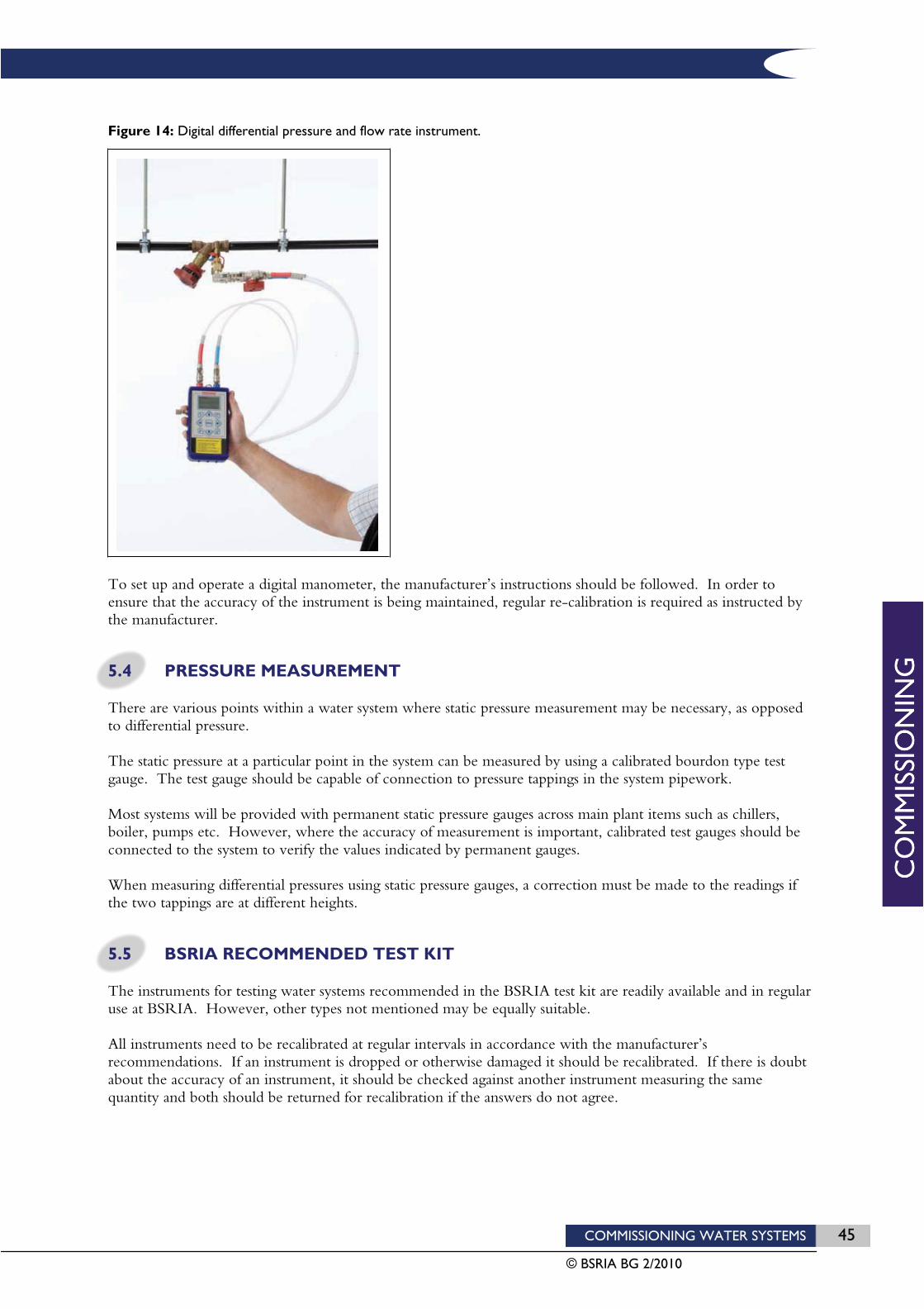
COMMISSIONING WATER SYSTEMS 45
© BSRIA BG 2/2010
Figure 14: Digital differential pressure and flow rate instrument.
To set up and operate a digital manometer, the manufacturer’s instructions should be followed. In order to ensure that the accuracy of the instrument is being maintained, regular re-calibration is required as instructed by the manufacturer.
5.4 PRESSURE MEASUREMENT
There are various points within a water system where static pressure measurement may be necessary, as opposed to differential pressure.
The static pressure at a particular point in the system can be measured by using a calibrated bourdon type test gauge. The test gauge should be capable of connection to pressure tappings in the system pipework.
Most systems will be provided with permanent static pressure gauges across main plant items such as chillers, boiler, pumps etc. However, where the accuracy of measurement is important, calibrated test gauges should be connected to the system to verify the values indicated by permanent gauges.
When measuring differential pressures using static pressure gauges, a correction must be made to the readings if the two tappings are at different heights.
5.5 BSRIA RECOMMENDED TEST KIT
The instruments for testing water systems recommended in the BSRIA test kit are readily available and in regular use at BSRIA. However, other types not mentioned may be equally suitable.
All instruments need to be recalibrated at regular intervals in accordance with the manufacturer’s recommendations. If an instrument is dropped or otherwise damaged it should be recalibrated. If there is doubt about the accuracy of an instrument, it should be checked against another instrument measuring the same quantity and both should be returned for recalibration if the answers do not agree.
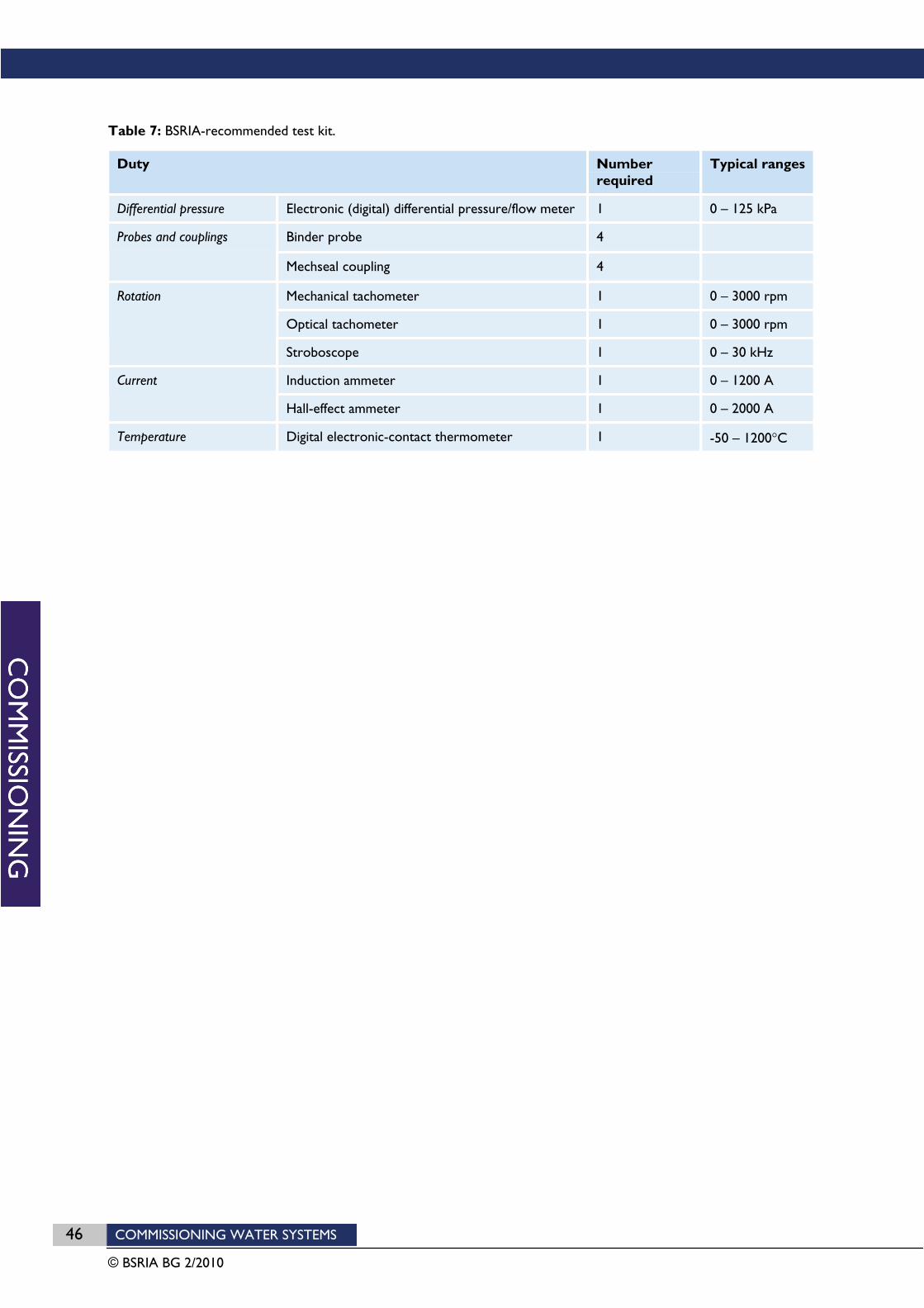
46 COMMISSIONING WATER SYSTEMS
© BSRIA BG 2/2010
Table 7: BSRIA-recommended test kit.
Duty Number required
Typical ranges
Differential pressure Electronic (digital) differential pressure/flow meter 1 0 – 125 kPa
Binder probe 4Probes and couplings
Mechseal coupling 4
Mechanical tachometer 1 0 – 3000 rpm
Optical tachometer 1 0 – 3000 rpm
Rotation
Stroboscope 1 0 – 30 kHz
Induction ammeter 1 0 – 1200 A Current
Hall-effect ammeter 1 0 – 2000 A
Temperature Digital electronic-contact thermometer 1 -50 – 1200 C

COMMISSIONING WATER SYSTEMS 47
© BSRIA BG 2/2010
6 Commissioning procedures The commissioning specialist can only organise and plan their activities from the time of their appointment. On a well-considered project, they will be called upon to respond to the requirements of a commissioning specification.
6.1 ORGANISATION AND PLANNING
The commissioning specialist will need to prepare for commissioning by obtaining all the relevant information about the system, and carrying out pre-commissioning checks on the completed system. The specialist will need to:
Establish and agree channels of communication and liaison procedures with all relevant parties connected with the contract: for example, the architect, consulting services engineer, installer and the controls manufacturer.
Obtain the final installation report from the installer, certifying that the system is complete.
Obtain and study the parts of the specification and all other documentation against which the commissioning service has been quoted.
Obtain and study the system schematic drawings, check that the information is complete and that sufficient flow measurement and regulating devices have been included.
Obtain and study the latest installation drawings, and identify potential difficulties in accessing the flow measurement devices and regulating valves.
Obtain the characteristics of the flow measurement devices and decide upon the range and type of differential pressure measurement instruments required.
Obtain and study the wiring diagrams for all the electrical supply and control equipment associated with the water distribution systems, including motor control circuit details and interlock arrangements.
Obtain the manufacturers’ setting-to-work, operating and maintenance instructions for all the water distribution system components and associated electrical equipment.
Prepare pro forma test sheets, filling in design and manufacturers’ data where appropriate.
Examine on site the basic system operating features relevant to commissioning. A pre-commissioning checklist should be employed, an example of which is included in Part D.
If the installation is found to be incomplete or to require remedial work, obtain from the installers a programme of work for its completion.
6.2 SETTING TO WORK
Any defects outstanding from the pre-commissioning checks must be completed before the system and its components are set-to-work.
The major system components should then be set-to-work, using pro forma checklists of the type illustrated in section 8.
The system installer should attend the setting-to-work process. No equipment should be left running until all parties are in agreement that it is safe to do so.
Pump tests will comprise a shut-off head test and preliminary flow rate check as described in the following paragraphs.

48 COMMISSIONING WATER SYSTEMS
© BSRIA BG 2/2010
Pump shut-off head test To verify the operational performance of a pump it is necessary to check the measured performance against test data provided by the manufacturer.
The performance test should be carried out as follows.
1. Connect a suitable differential pressure gauge across the suction and discharge pressure test points of the pump.
2. With the pump running, slowly close the discharge valve. Do not run in this condition for longer than 15 minutes (check manufacturer’s guidance) or the pump will overheat and may be damaged.
3. Determine the shut-off pressure differential, check against the manufacturer’s data for zero flow then slowly re-open the discharge valve.
4. Where the test result coincides with the manufacturer’s test data proceed to the next step. Otherwise draw a curve parallel to that shown on the published data, starting at the shut-off head pressure.
5. Record the total pressure with the differential pressure gauge at full flow rate and read the actual flow from the manufacturer’s data, or from the corrected graph curve as appropriate.
6. If the performance is inadequate refer back to the installer and designer.
Preliminary flow rate check With all “normally open” branch isolating valves valves fully open, and all control valves set to full flow through terminal units, measure and record the total flow rate from the pump and compare this with the total system design flow rate. Where necessary, reduce the pump speed to provide a flow rate in the range 100-110% of the pump design flow rate.
Where the initial measured flow rate is less than 100% of the design flow rate with all branch isolating valves fully open, then a value of less than 100% will inevitably result at the conclusion of the regulating process. Regulation of a system with the pump capable of less than 100% of design flow rate should not be attempted without formally advising the installing contractor and system designer. The reason for the low flow rate condition should be investigated and, where possible, corrective measures implemented prior to commencing regulation.
6.3 FULL SYSTEM SCAN
Before commencing with the regulation of flow rates, it is usually advisable, where circumstances permit, to undertake a complete scan of the flow rats throughout the system. The results of this scan will immediately highlight problem areas i.e. index branches in unexpected locations. This will allow time for any problems to be investigated and resolved as soon as possible rather than waiting discover problems as the work proceeds.
6.4 REGULATION PROCEDURE
The on-site regulation of a water distribution system involves three basic processes.
Tests at the pump to ensure that the pump is performing in accordance with the manufacturer’s data and is capable of providing the specified design flow rate for the system.
Regulation of flow rates i.e. the adjustment of branch regulating valves in order to achieve the correct design flow rates for each branch within the tolerances specified by the designer. This may include “proportional balancing” in circuits with manually operated regulating valves, whereby branch flow rates are balanced relative to one another, to achieve the correct proportions of flow through each branch.
The adjustment of the total flow rate generated by the pump to obtain the maximum design flow rate. This is best achieved by varying the pump speed, or by substituting the pump impeller, as appropriate, and as agreed with the designer.

COMMISSIONING WATER SYSTEMS 49
© BSRIA BG 2/2010
6.5 PROPORTIONAL BALANCING
Proportional balancing is a technique which is applicable to circuits with manually operated regulating valves and flow measurement devices. The procedure enables the commissioning specialist to regulate the valves until all of the sub-branches are receiving their correct proportion of the overall flow.
Consider a system (5) feeding several identical terminal units. The quantity of water passing through each terminal unit represents a certain proportion or percentage of the total flow entering the system. In an unbalanced condition the terminals closest to the system inlet will receive a larger proportion of the flow than those further away. To proportionally balance the system, regulating valves must be adjusted so that the terminal units share the flow in the correct proportions. Once the system has been balanced, the overall flow rate can be regulated to achieve the correct design values.

50 COMMISSIONING WATER SYSTEMS
© BSRIA BG 2/2010
Figure 15: The basis of proportional balancing.
Proportional balancing must follow a set procedure if the results are to be successful. This procedure applies equally to multiple terminal branches fed from the same sub-branch, or multiple sub-branches fed from the same floor branch, or to multiple floor branches fed from the same riser.
0 . 1 0 k g / s
0 . 0 4 k g / s
4 0 %
D e s i g n
A c t u a l
% D F R
0 . 1 0 k g / s
0 . 0 7 k g / s
7 0 %
0 . 1 0 k g / s
0 . 1 0 k g / s
1 0 0 %
0 . 1 0 k g / s
0 . 1 3 k g / s
1 3 0 %
0 . 1 0 k g / s
0 . 1 6 k g / s
1 6 0 %
D e s i g n
A c t u a l
% D F R
0 . 1 0 k g / s
0 . 0 9 k g / s
9 0 %
0 . 1 0 k g / s
0 . 0 9 k g / s
9 0 %
0 . 1 0 k g / s
0 . 0 9 k g / s
9 0 %
0 . 1 0 k g / s
0 . 0 9 k g / s
9 0 %
0 . 1 0 k g / s
0 . 0 9 k g / s
9 0 %
D e s i g n
A c t u a l
% D F R
0 . 1 0 k g / s
0 . 1 0 k g / s
1 0 0 %
0 . 1 0 k g / s
0 . 1 0 k g / s
1 0 0 %
0 . 1 0 k g / s
0 . 1 0 k g / s
1 0 0 %
0 . 1 0 k g / s
0 . 1 0 k g / s
1 0 0 %
0 . 1 0 k g / s
0 . 1 0 k g / s
1 0 0 %
S y s t e m
b e f o r e
b a l a n c i n g
S y s t e m
a f t e r
b a l a n c i n g
S y s t e m
a f t e r f l o w
r e g u l a t i o n
COMMISSIONING WATER SYSTEMS 51
© BSRIA BG 2/2010
Where to start It is essential to remember that the adjustment of any regulating valve will cause a change in the flow balance between upstream branches, whereas it will cause no disturbance to the flow balance established between downstream branches. As a consequence, the balancing procedure must always start at system extremities and work its way back towards the pump.
In practice, this will involve commencing the process by balancing the flows between terminal branches at the ends of branch runs. Once these are in balance, the flows between the sub-branches feeding those terminal branches can be balanced. Once these are in balance the main branches serving those sub-branches can be balanced, and so on.
Percentage design flow rate Proportional balancing aims to ensure that each of the branches being balanced ends up receiving the same proportion of its design flow rate. These proportions are commonly expressed as percentages. Hence the aim of proportional balancing is to achieve the same percentage of the design flow rate for each branch (i.e. %DFR)
Where
%DFR = (measured flow rate / design flow rate) x 100
The design flow rates (as specified by the designer) may differ for each of the branches. Hence, the %DFR values may have to be calculated separately for each branch.
Establishing the index branch The proportional balancing procedure requires that for the group of branches being balanced, the “index” branch must be identified at the outset. The index branch is the branch which has the highest pressure drop at its design flow rate, and consequently, with the system in an un-balanced condition, receives the lowest percentage of its design flow rate value (%DFR).
In most cases, the index branch will be the most remote branch (i.e. the one at the end of the run) simply because this incurs the longest pipe run and hence the most resistance to flow. However, it may sometimes be the case that the index branch is in the middle of the run, especially if one of these branches has a particularly long pipe run or serves a high resistance terminal unit.
The reason for identifying the index branch at the outset is that for the proportional balancing procedure to work, it is essential that the most remote terminal is made to be the “least favoured”, even if it is not the index.
For example, in a sub-branch having five terminals with terminal five being the end or most remote terminal, it may be found in the initial scan that, say, terminal three is has the lowest %DFR value and is therefore the index.
In such a case, the regulating valve serving terminal five must be throttled until terminal five becomes the least favoured. When this is done, terminal three is still the index, as its regulating valve will be fully open, but terminal five is now the least favoured. Since the most remote terminal is now the least favoured, proportional balancing can begin.
Is it the aim to achieve design flow rates? It is not the aim of proportional balancing to achieve the design flow rates for each branch, but merely to achieve the correct proportions of the total flow through each branch. As long as the flows are balanced in their correct proportions, then the overall flow can be increased or decreased later to achieve the design values. Hence, the aim is merely to achieve the same %DFR value through each branch.
Having said this, it is nevertheless important that the flow balance achieves %DFR values as close as possible to the design values. It is noticeable that a proportional balance achieved at say, 50%DFR through each branch may not hold very well when the total flow is later increased to 100%.
It is therefore good practice to ensure that before starting the balance, the total flow rate entering the circuit is slightly more than its design value (typically about 110% of design). The balancing procedure will cause this flow rate to drop as valves are throttled and the overall system resistance increases. By the time a balance is achieved,
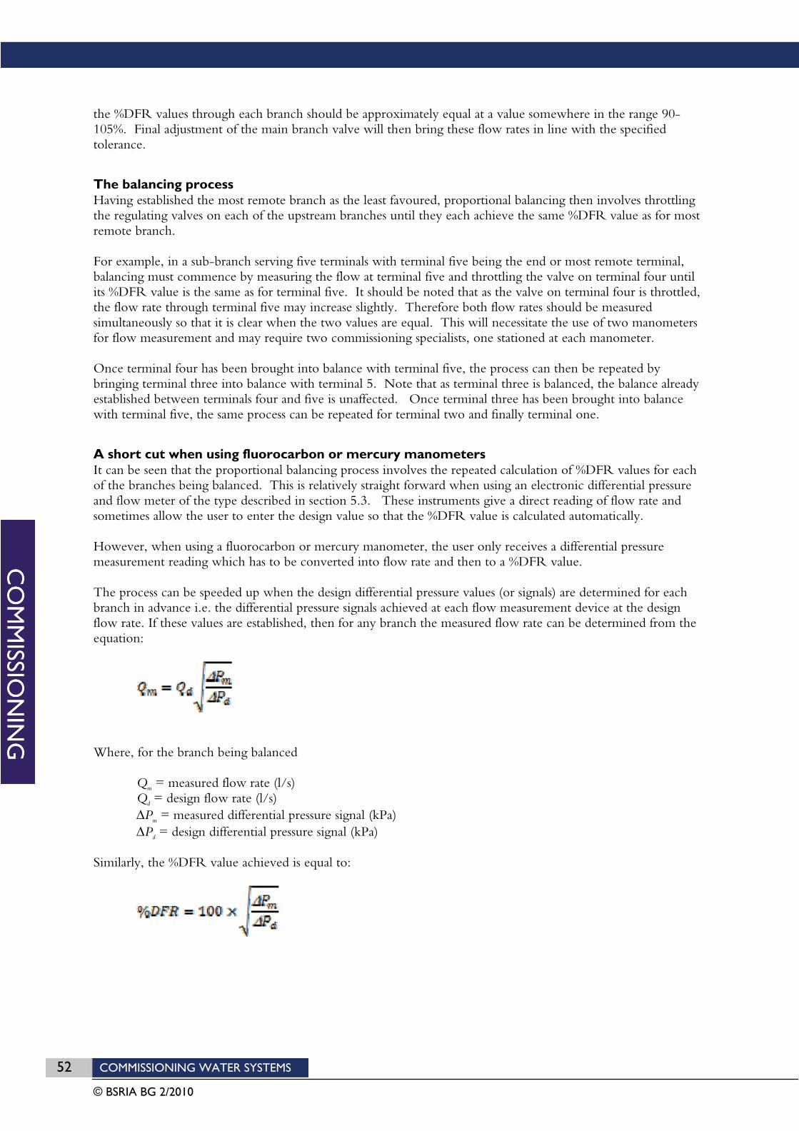
52 COMMISSIONING WATER SYSTEMS
© BSRIA BG 2/2010
the %DFR values through each branch should be approximately equal at a value somewhere in the range 90-105%. Final adjustment of the main branch valve will then bring these flow rates in line with the specified tolerance.
The balancing process Having established the most remote branch as the least favoured, proportional balancing then involves throttling the regulating valves on each of the upstream branches until they each achieve the same %DFR value as for most remote branch.
For example, in a sub-branch serving five terminals with terminal five being the end or most remote terminal, balancing must commence by measuring the flow at terminal five and throttling the valve on terminal four until its %DFR value is the same as for terminal five. It should be noted that as the valve on terminal four is throttled, the flow rate through terminal five may increase slightly. Therefore both flow rates should be measured simultaneously so that it is clear when the two values are equal. This will necessitate the use of two manometers for flow measurement and may require two commissioning specialists, one stationed at each manometer.
Once terminal four has been brought into balance with terminal five, the process can then be repeated by bringing terminal three into balance with terminal 5. Note that as terminal three is balanced, the balance already established between terminals four and five is unaffected. Once terminal three has been brought into balance with terminal five, the same process can be repeated for terminal two and finally terminal one.
A short cut when using fluorocarbon or mercury manometers It can be seen that the proportional balancing process involves the repeated calculation of %DFR values for each of the branches being balanced. This is relatively straight forward when using an electronic differential pressure and flow meter of the type described in section 5.3. These instruments give a direct reading of flow rate and sometimes allow the user to enter the design value so that the %DFR value is calculated automatically.
However, when using a fluorocarbon or mercury manometer, the user only receives a differential pressure measurement reading which has to be converted into flow rate and then to a %DFR value.
The process can be speeded up when the design differential pressure values (or signals) are determined for each branch in advance i.e. the differential pressure signals achieved at each flow measurement device at the design flow rate. If these values are established, then for any branch the measured flow rate can be determined from the equation:
Where, for the branch being balanced
Qm = measured flow rate (l/s) Qd = design flow rate (l/s)
Pm = measured differential pressure signal (kPa) Pd = design differential pressure signal (kPa)
Similarly, the %DFR value achieved is equal to:

COMMISSIONING WATER SYSTEMS 53
© BSRIA BG 2/2010
Furthermore, to bring any two branches containing the same flow measurement device (with the same kvs value) into balance, the measured differential pressure signal for the branch being balanced must be adjusted until its value is as predicted by the following equation:
Where
Pm = measured differential pressure signal in the branch being balanced (kPa) Plm = measured differential pressure signal in the least favoured (i.e. most remote) branch (kPa) Pd = design differential pressure signal in the branch being balanced (kPa) Pld = design differential pressure signal for the least favoured (i.e. most remote) branch (kPa)
6.6 FLOW SETTING
Regulation of flows in circuits fitted with self-acting valves (such as constant flow regulators, differential pressure control valves, or pressure independent control valves) usually requires the straight forward adjustment of the valves until the branch in which it is installed receives its design flow rate value within the specified tolerances.
Because the valves are self-acting, once they are set they will maintain the set flow condition regardless of valve adjustments in other branches. As a consequence, the setting of self-acting valves can proceed in any order.There is no need to follow a set proportional balancing procedure, nor is there a need to differentiate between the index and least favoured sub-branches.
Provided that the pressure differential across each self-acting valve is within the manufacturer’s stated operating range, the valve can be set to the required design flow rate in the knowledge that this flow will be maintained. The pressure differential across each valve can usually be verified by measuring across pressure tappings built into the valve itself or across tappings provided in the adjacent pipework.
Setting constant flow regulators (cartridge type) Cartridge type constant flow regulators require no setting of the valve at all. Provided that the pressure differential across the valve is within the manufacturer’s recommended limits, then the specified flow rate should be achieved. It is not even essential to measure the pressure differential across every valve. Provided that there is sufficient pressure available at the most remote constant flow regulator, then it can be safely assumed that all of the upstream constant flow regulators will have enough pressure as well.
Setting constant flow regulators (DPCV type) For constant flow regulators that comprise a DPCV holding pressure constant across a fixed resistance, the valve must be set by adjusting the DPCV until the required flow rate is achieved. Once achieved, provided that the pressure differential across the valve is maintained within the manufacturer’s recommended limits, then the set flow rate should also be maintained.
Setting DPCVs DPCVs can be set by adjusting the valve until the required flow rate in the pipe is achieved. Once achieved, provided that the pressure differential across the valve is maintained within the manufacturer’s recommended limits, then the set flow rate should also be maintained.
In the case of fixed differential pressure DPCVs, (i.e. DPCVs that are factory set to control a fixed pressure) no adjustment is possible.
Setting PICVs For PICVs, there is usually a flow adjustment device on the valve that enables flow rate to be set. This usually takes the form of an adjustable dial with a scale indicating flow rate. Once achieved, provided that the pressure differential across the valve is maintained within the manufacturer’s recommended limits, then the set flow rate should also be maintained.

54 COMMISSIONING WATER SYSTEMS
© BSRIA BG 2/2010
6.7 FLOW MEASUREMENT ACCURACY
If during the process of proportional balancing or flow setting it becomes apparent that the summation of measured flow rates through a group of sub-branches is not equal to that in the branch feeding them (within acceptable limits), then it is likely that there is an error in some poor all of the flow measurement devices. The cause of the error should be investigated initially be the commissioning specialist. The most common causes of flow measurement error are as follows.
Variations in upstream pipe diameter. Published valve kvs values are based on steel pipe connections, and copper or plastic pipes may have different internal diameters.
Burrs on the ends of pipes which effectively reduce the pipe diameter at inlet to the flow measurement device.
The intrusion of excess jointing compound which reduces the flow area at inlet to the flow measurement device.
Bends, tees and reducers in the approach pipework to the device.
These common causes of flow measurement inaccuracy are more likely to produce a negative error rather than a positive one. In other words, the measured flow is more likely to be less than the actual flow.

COMMISSIONING WATER SYSTEMS 55
© BSRIA BG 2/2010
7 Example method statements This section provides alternative commissioning procedures applicable to different pipework systems depending on the design layout and the choice of commissioning devices.
It should be noted that heating installations should be balanced warm, and pressurisation units only pressurised sufficiently to permit filling and venting of the installation. It is dangerous to take measurements that require entry of the waterway in systems with temperatures in excess of 43°C. If balancing at temperatures above 43°C is essential, it may be necessary to consider suitable protective clothing or equipment. A medium or high temperature system (i.e. with circulating temperatures greater than 100°C) must not, under any circumstances, be commissioned at operating temperature as a serious injury may result. For further obligations regarding safety, reference should be made to the Health & Safety at Work Act 1974.
7.1 PRIMARY CIRCUITS
The example shown in Figure 16 is a heating system, but it could equally be a chilled water system.
Figure 16: Typical primary circuit arrangement.

56 COMMISSIONING WATER SYSTEMS
© BSRIA BG 2/2010
For multiple pumps arranged in parallel, as shown in Figure 16, the total flow rate from the pumps will not necessarily be the sum of the individual flow rates through each pump operating on their own. Therefore, the primary circuit must be commissioned with all pumps running, and then checks made to ensure that flows through individual pumps are within acceptable operating limits. The balancing procedure is therefore as follows:
1. Fully close all the valves necessary to isolate the secondary circuits. Fully open the primary circuit isolating valves serving the boilers (but keeping flushing by-pass valves closed).
2. Switch on boiler pumps 1-3 to operate simultaneously and set the variable speed drives for each pump to full speed.
3. Adjust pump speeds down until all pumps flow rates are within 100-110% of their design values. Reduce pump speeds by making small simultaneous reductions in speed at each pump.
4. Record flow rates, pump inlet and outlet gauge pressures, motor frequencies and kW values for each pump.
5. Check that with all pumps running, the pump inlet gauge pressures are all greater than the manufacturer’s stated net positive suction head value. If necessary increase the setting at the pressurisation unit until pump inlet pressures are greater than this value.
6. Switch off all pumps except pump 1.
7. For pump 1 measure and record the flow rate, pump inlet and outlet gauge pressures, motor frequency and kW values. Check that the flow rate measured within the designer’s specified tolerance range.
8. Repeat stages 6 and 7 for each of the remaining boiler circuits in turn.
7.2 CONSTANT FLOW SECONDARY CIRCUITS
Balancing procedures are provided for the following system types:
Regulating flows in circuits with fixed orifice double regulating valves Figure 17 shows a system feeding to fan coil units. The procedure described is equally applicable to any system serving terminal units for which the heat output is the result of the forced convection of air across a heating or cooling coil (i.e. fan driven). This includes air handling unit coils and active chilled beams.
As shown in Figure 17 the method for controlling heating or cooling output from the fan coil units is by means of 4 port control valves which divert flow through an integral by-pass when the room air temperature reaches its set value. Large coils might be fitted with 3 port control valves with a separate rather than integral diverting by-pass.
This type of system will have a constant flow rate from the pump and there are no self-acting valves. This means that the process of flow regulation involves proportional balancing.

COMMISSIONING WATER SYSTEMS 57
© BSRIA BG 2/2010
Figure 17: A system feeding to fan coil units.
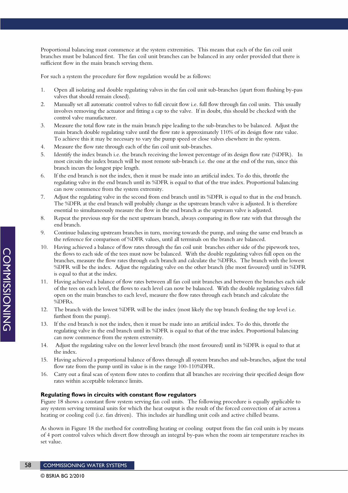
58 COMMISSIONING WATER SYSTEMS
© BSRIA BG 2/2010
Proportional balancing must commence at the system extremities. This means that each of the fan coil unit branches must be balanced first. The fan coil unit branches can be balanced in any order provided that there is sufficient flow in the main branch serving them.
For such a system the procedure for flow regulation would be as follows:
1. Open all isolating and double regulating valves in the fan coil unit sub-branches (apart from flushing by-pass valves that should remain closed).
2. Manually set all automatic control valves to full circuit flow i.e. full flow through fan coil units. This usually involves removing the actuator and fitting a cap to the valve. If in doubt, this should be checked with the control valve manufacturer.
3. Measure the total flow rate in the main branch pipe leading to the sub-branches to be balanced. Adjust the main branch double regulating valve until the flow rate is approximately 110% of its design flow rate value. To achieve this it may be necessary to vary the pump speed or close valves elsewhere in the system.
4. Measure the flow rate through each of the fan coil unit sub-branches. 5. Identify the index branch i.e. the branch receiving the lowest percentage of its design flow rate (%DFR). In
most circuits the index branch will be most remote sub-branch i.e. the one at the end of the run, since this branch incurs the longest pipe length.
6. If the end branch is not the index, then it must be made into an artificial index. To do this, throttle the regulating valve in the end branch until its %DFR is equal to that of the true index. Proportional balancing can now commence from the system extremity.
7. Adjust the regulating valve in the second from end branch until its %DFR is equal to that in the end branch. The %DFR at the end branch will probably change as the upstream branch valve is adjusted. It is therefore essential to simultaneously measure the flow in the end branch as the upstream valve is adjusted.
8. Repeat the previous step for the next upstream branch, always comparing its flow rate with that through the end branch.
9. Continue balancing upstream branches in turn, moving towards the pump, and using the same end branch as the reference for comparison of %DFR values, until all terminals on the branch are balanced.
10. Having achieved a balance of flow rates through the fan coil unit branches either side of the pipework tees, the flows to each side of the tees must now be balanced. With the double regulating valves full open on the branches, measure the flow rates through each branch and calculate the %DFRs. The branch with the lowest %DFR will be the index. Adjust the regulating valve on the other branch (the most favoured) until its %DFR is equal to that at the index.
11. Having achieved a balance of flow rates between all fan coil unit branches and between the branches each side of the tees on each level, the flows to each level can now be balanced. With the double regulating valves full open on the main branches to each level, measure the flow rates through each branch and calculate the %DFRs.
12. The branch with the lowest %DFR will be the index (most likely the top branch feeding the top level i.e. furthest from the pump).
13. If the end branch is not the index, then it must be made into an artificial index. To do this, throttle the regulating valve in the end branch until its %DFR is equal to that of the true index. Proportional balancing can now commence from the system extremity.
14. Adjust the regulating valve on the lower level branch (the most favoured) until its %DFR is equal to that at the index.
15. Having achieved a proportional balance of flows through all system branches and sub-branches, adjust the total flow rate from the pump until its value is in the range 100-110%DFR.
16. Carry out a final scan of system flow rates to confirm that all branches are receiving their specified design flow rates within acceptable tolerance limits.
Regulating flows in circuits with constant flow regulators Figure 18 shows a constant flow system serving fan coil units. The following procedure is equally applicable to any system serving terminal units for which the heat output is the result of the forced convection of air across a heating or cooling coil (i.e. fan driven). This includes air handling unit coils and active chilled beams.
As shown in Figure 18 the method for controlling heating or cooling output from the fan coil units is by means of 4 port control valves which divert flow through an integral by-pass when the room air temperature reaches its set value.
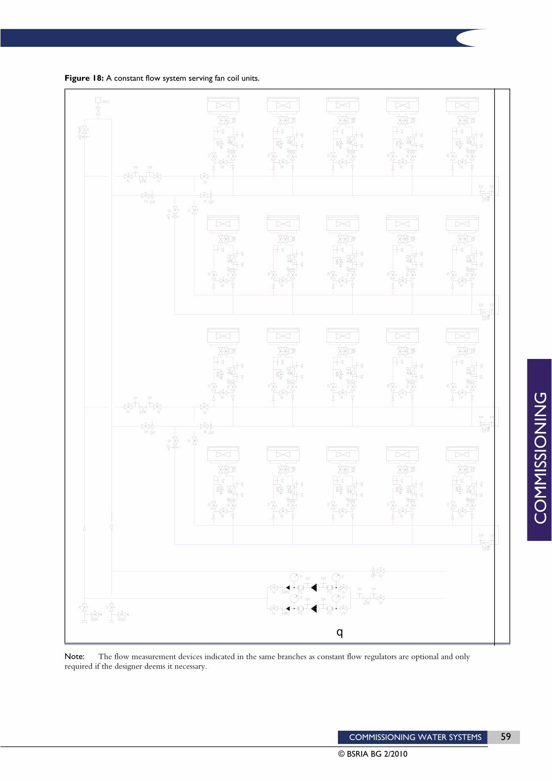
COMMISSIONING WATER SYSTEMS 59
© BSRIA BG 2/2010
Figure 18: A constant flow system serving fan coil units.
Note: The flow measurement devices indicated in the same branches as constant flow regulators are optional and only required if the designer deems it necessary.

60 COMMISSIONING WATER SYSTEMS
© BSRIA BG 2/2010
Since constant flow regulators are self-acting valves, it does not make any difference in which order they are tested or set.
For such a system, the procedure for flow regulation in each of the terminal branches would be as follows:
1. Open all isolating valves in the sub-branches (apart from flushing by-pass valves which should remain closed).
2. Manually set all constant flow regulators to full circuit flow i.e. full flow through terminal units. This usually involves removing the actuator and fitting a cap to the valve. If in doubt, this should be checked with the control valve manufacturer.
3. Using the built-in pressure tappings, measure the pressure differential across the CFR installed in the index terminal branch. The index branch is usually either the branch furthest from the pump or the one with the highest resistance terminal unit. If in doubt, measurements should be taken in both of these locations.
4. Check that the value (or values) measured is/are within the manufacturer’s stated pressure differential operating range for the CFR. If not, change the pump speed or close valves elsewhere in the system until the measured pressure differential is within the stated operating range.
5. If the CFRs are of the type that need to be set, set the flow rates for each valve to their specified design values.
6. If the terminal branches containing CFRs also have flow measurement devices installed, measure the flow rates at each of these points to confirm that the set design flow rate for each terminal is being achieved within acceptable tolerance limits.
7. If the terminal branches containing CFRs do not have flow measurement devices installed, measure the total flow rate in the main branch. Isolate each terminal branch in turn, each time recording the drop in flow through the main branch. Confirm that in each case, the drop in flow is equal to the set design flow rate through the isolated branch.
8. Confirm that the flow rate measured at the main branch flow measurement device is equal to the sum of downstream CFR settings. If this is not the case investigate the cause and, if necessary, report to the designer.
7.3 VARIABLE FLOW SECONDARY CIRCUITS
Balancing procedures are provided for the following system types.
Radiators, panels and natural convectors with DPCV protectionFigure 19 shows a system feeding to radiators. The procedure described is equally applicable to any system serving terminal units for which the heat output is the result of the natural convection of air across the heat emitter surface (i.e no fans involved). This includes radiant panels and passive chilled beams.
As shown in Figure 19 the method for controlling heat output from the radiators is by means of thermostatic radiator valves (TRVs) which close when the room air temperature reaches its set value. TRVs could equally be replaced by actuated 2 port control valves with remote sensors.
If the system is large then DPCVs are likely to be installed on main branches to ensure that TRVs do not need to close against excessive pressures.
Some TRVS are settable and the setting value can be estimated in advance by the TRV manufacturer. If the system is fitted with this type of TRV then the valves can be simply set to their required values. However, it is advisable to check the balance by confirming that the return water temperature from each radiator is within the tolerance limits indicated in Table 8 of this guide.
COMMISSIONING WATER SYSTEMS 61
© BSRIA BG 2/2010
Figure 19: A system feeding to radiators.

62 COMMISSIONING WATER SYSTEMS
© BSRIA BG 2/2010
If the TRVS are not settable, then lockshield valves will be used for flow balancing. Flow balancing must commence at the system extremities. This means that each of the radiator branches must be balanced first. The radiator branches can be balanced in any order provided that there is sufficient flow in the main branch.
For such a system the procedure for flow regulation would be as follows:
1. Remove TRV heads and fully open all lockshield valves in radiator sub-branches.
2. Measure the total flow rate in the branch pipe leading to the sub-branches to be balanced. Adjust the main double regulating valve until the flow rate is approximately 110% of its design flow rate value. To achieve this it may be necessary to vary the pump speed or close valves elsewhere in the system.
3. Operate the system with its flow temperature at a value as close as possible to its design value. If the flow temperature is controlled by a weather compensated controller, this should be adjusted to ensure that a constant flow temperature is maintained during the balancing.
4. Manually balance the system by throttling each radiator lockshield radiator valve until all return pipes register an equal temperature measured by a contact thermometer consistently applied. This procedure must start with the most remote radiator branch and work back towards the beginning of the branch. Note that for each adjustment of a lockshield valve it will be necessary to allow time for the contact temperature of the return pipe to stabilise. This may take a few minutes.
5. Having achieved a balance of flow rates through the radiator branches either side of the pipework tees, the flows to each side of the tees must now be balanced. With the double regulating valves full open on the branches, measure the flow rates through each branch and calculate the %DFRs. The branch with the lowest %DFR will be the index. Adjust the regulating valve on the other branch (the most favoured) until its %DFR is equal to that at the index.
6. Having proportionally balanced the flows between the radiator circuits the DPCVs can now be set. Open the DPCV to its full open position, measure the total sub-branch flow rate at the flow measurement device adjacent to the DPCV. Throttle flows in other circuits or adjust the pump speed until the indicated total flow rate through the DPCV when fully open is 110% of the design value. In situations where there is no access to other floors or the pump, a DRV could be installed alongside the DPCV to enable flow to be regulated flow down to 110%.
7. Measure the pressure differential across the DPCV using either its own built-in pressure tappings or across the tappings provided on either side of the valve. Check to ensure that the measured pressure differential is approximately equal to its specified design value and in all cases, is within the manufacturer’s stated operating range. If this is not the case throttle flows in other circuits or adjust the pump speed until the pressure differential cross the valve is approximately equal to its design value.
8. Adjust the DPCV until the indicated flow rate is 100% of the design value.
9. Measure and record the pressure differential between the pressure tappings adjacent to each of the DPCV capillary tube connections. This is the pressure being held constant by the DPCV across the entire branch. Check to ensure that this value does not exceed the maximum shut-off differential of any downstream thermostatic radiator valves.
Fan coil units, AHU coils and active beams with DPCV protection Figure 20 shows a variable flow system serving fan coil units. The following procedure is equally applicable to any system serving terminal units for which the heat output is the result of the forced convection of air across a heating or cooling coil (i.e. fan driven). This includes air handling unit coils and active chilled beams.
As shown in Figure 20 the method for controlling heating or cooling output from the fan coil units is by means of 2 port control valves which throttle the flow when the room air temperature reaches its set value.
If the system is large then DPCVs are likely to be installed on main branches to ensure that 2 port control valves do not need to close against excessive pressures.

COMMISSIONING WATER SYSTEMS 63
© BSRIA BG 2/2010
Figure 20: A variable flow system serving fan coil units.

64 COMMISSIONING WATER SYSTEMS
© BSRIA BG 2/2010
Proportional balancing must commence at the system extremities. This means that each of the fan coil unit branches must be balanced first. The branches can be balanced in any order provided that there is sufficient flow in the main branch serving them.
For such a system the procedure for flow regulation would be as follows:
1. Proportionally balance flow rates through fan coil unit branches by following steps 1-10 in the preceding procedure for constant flow systems.
2. Having balanced the flows between the terminal unit circuits the DPCV can now be set.
3. Open the DPCV to its full open position, measure the total sub-branch flow rate at the flow measurement device adjacent to the DPCV. Throttle flows in other circuits or adjust the pump speed until the indicated total flow rate through the DPCV when fully open is 110% of the design value. In situations where there is no access to other floors or the pump, a DRV could be installed alongside the DPCV to enable flow to be regulated flow down to 110%.
4. Measure the pressure differential across the DPCV using either its own built-in pressure tappings or across the tappings provided on either side of the valve. Check to ensure that the measured pressure differential is approximately equal to its specified design value and in all cases is within the manufacturer’s stated operating range. If this is not the case throttle flows in other circuits or adjust the pump speed until the pressure differential cross the valve is approximately equal to its design value.
5. Adjust the DPCV until the indicated flow rate is 100% of the design value.
6. Re-measure the flow rates through all downstream terminal units and record the results and valve settings. The results should indicate that flows are proportionally balanced and are within the appropriate tolerance range.
7. Measure and record the pressure differential between the pressure tappings adjacent to each of the DPCV capillary tube connections. This is the pressure being held constant by the DPCV across the entire branch. Check to ensure that this value does not exceed the maximum shut-off differential of any downstream 2 port control valves.
Fan coil units, AHU coils or chilled beams fitted with PICVs Figure 21 shows a variable flow system serving fan coil units. The following procedure is equally applicable to any system serving terminal units for which the heat output is the result of the forced convection of air across a heating or cooling coil (i.e. fan driven). This includes air handling unit coils and active chilled beams.
As shown in Figure 21 the method for controlling heating or cooling output from the fan coil units is by means of PICVs with integral 2 port control valves which throttle the flow when the room air temperature reaches its set value.

COMMISSIONING WATER SYSTEMS 65
© BSRIA BG 2/2010
Figure 21: A variable flow system serving fan coil units.
Note: The flow measurement devices indicated in the same branches as PICVs are considered optional and as deemed necessary by the designer.
66 COMMISSIONING WATER SYSTEMS
© BSRIA BG 2/2010
Since PICVs are self-acting valves, it does not make any difference in which order they are tested or set.
For such a system, the procedure for flow regulation in each of the terminal branches would be as follows:
1. Open all isolating valves in the terminal branches (apart from flushing by-pass valves which should remain closed).
2. For each PICV in any order, adjust the flow to the specified design value and record the setting.
3. Using the built-in pressure tappings, measure the pressure differential across the PICV installed in the index terminal branch. The index branch is usually either the branch furthest from the pump or the one with the highest resistance terminal unit. If in doubt, measurements should be taken in both of these locations.
4. Check that the value (or values) measured is/are within the manufacturer’s stated pressure differential operating range for the PICV. If not, change the pump speed or close valves elsewhere in the system until the measured pressure differential is within the stated operating range.
5. At this stage there is an option to accept the system as balanced and to proceed to stage 8 below. Alternatively, if flow settings are required to be proven, then the following stages 6 or 7 should be completed. The designer or witnessing authority should advise which option is appropriate.
6. If the terminal branches containing PICVs also have flow measurement devices installed, measure the flow rates at each of these points to confirm that the set design flow rate for each terminal is being achieved within the specified tolerance limits.
7. If the terminal branches containing PICVs do not have flow measurement devices installed, measure the total flow rate in the sub-branch feeding the terminals. Isolate each terminal branch in turn, each time recording the drop in flow through the sub-branch. Confirm that in each case, the drop in flow is equal to the set design flow rate through the isolated branch.
8. Confirm that the flow rate measured at the main branch flow measurement device is equal to the sum of downstream PICV settings. If this is not the case investigate the cause and, if necessary, report to the designer.
7.4 SETTING OF TOTAL FLOW RATE FROM THE PUMP
Having completed the regulation of flow rates around the system, a check should be made on the total flow rate from the pump.
Using the pump speed controller, the pump flow rate should be adjusted to its design flow rate value within the specified tolerance range.
In order to demonstrate system performance in variable flow systems at full and minimum load conditions (and thereby quantify the pump energy saving), pump flow and operating pressure differentials should be measured, recorded and plotted on the manufacturer’s pump curve at a minimum of four operating points:
with all control valves set to full flow through terminal units;
with all control valves closed i.e. set to zero flow through terminal units;
at two intermediate points, with a sufficient number of valves closed, to give approximately 30% and 60% of design maximum flow.
For each of these conditions, the pump energy consumption, as indicated by the manufacturer’s pump curve should be recorded. These values should be included on the commissioning results.

COMMISSIONING WATER SYSTEMS 67
© BSRIA BG 2/2010
8 Reporting and documentation 8.1 REPORTING
During construction, it is recommended that formal reports relating to commissioning are produced at four key control points (see BSRIA Technical Memorandum, TM 1/88: Commissioning of HVAC Systems – Division of Responsibilities).
System design is commissionable report
Post-installation report
System cleanliness report
System commissionable report.
A prime purpose of these reports is to form bridges over the boundaries of responsibilities between the parties involved.
8.2 DOCUMENTATION
An essential part of each report will be the completed pro forma checklists utilised as aide-memoires for both implementation and supervision.
Potential disputes will be minimised substantially if report forms, including the use of pro formas, can be agreed as early as possible. At the most vulnerable points of potential failure in communication are at the design/installation, design/commissioning, installation/commissioning interfaces, the same pro forma may be used advantageously by each party for their own requirements within the same common objective. For example, a design information checklist may be used:
By the designer, to help ensure tasks are completed
By the installer, to help ensure that sufficient information is available to proceed with procurement and installation
By the commissioning specialist, to help ensure that the design is commissionable
By the main contractor, as a control tool and an important supportive addendum to a report that the system design is commissionable.
8.3 EXAMPLE PRO FORMAS
The use of pro formas can save time both in executing the necessary tasks and in providing an effective vehicle through which anomalies and/or deficiencies may be communicated to other parties. Well thought-out pro formas can:
Aid the efficient execution of the commissioning tasks
Help the control of quality and progress of the commissioning tasks
Provide a convenient means of comparing test results with design values
Serve as a permanent record of commissioning data to be included in the project’s operating and maintenance manual.
68 COMMISSIONING WATER SYSTEMS
© BSRIA BG 2/2010
A selection of some example pro formas are provided in the following pages:
Design information checklist
Continuous inspection checklist
Final inspection checklist - mechanical
Final inspection checklist - electrical
Pre-commissioning checklist - mechanical
Co-ordination checklist
Setting-to-work checklist - centrifugal pump - set
Plant performance test sheet – pump
Plant performance test sheet - heating/cooling
Water balance test sheet
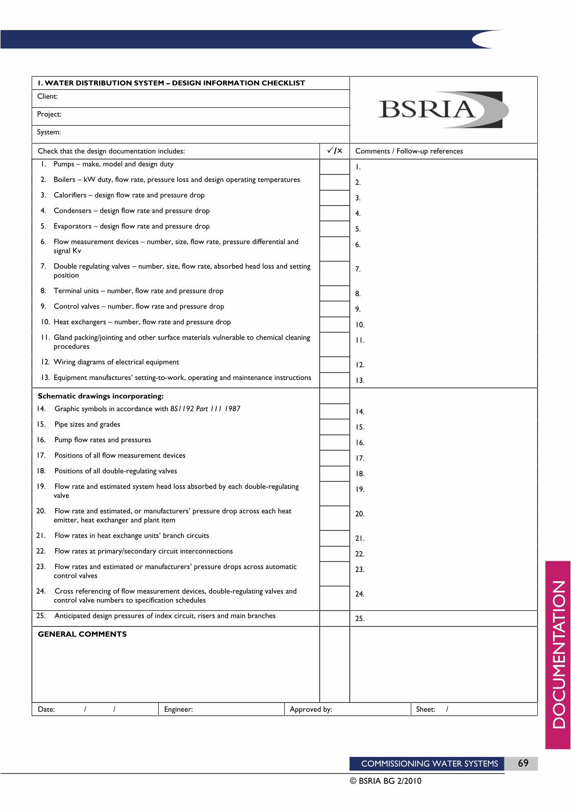
COMMISSIONING WATER SYSTEMS 69
© BSRIA BG 2/2010
1. WATER DISTRIBUTION SYSTEM – DESIGN INFORMATION CHECKLIST
Client:
Project:
System:
Check that the design documentation includes: / Comments / Follow-up references
1. Pumps – make, model and design duty 1.
2. Boilers – kW duty, flow rate, pressure loss and design operating temperatures 2.
3. Calorifiers – design flow rate and pressure drop 3.
4. Condensers – design flow rate and pressure drop 4.
5. Evaporators – design flow rate and pressure drop 5.
6. Flow measurement devices – number, size, flow rate, pressure differential and signal Kv
6.
7. Double regulating valves – number, size, flow rate, absorbed head loss and setting position
7.
8. Terminal units – number, flow rate and pressure drop 8.
9. Control valves – number, flow rate and pressure drop 9.
10. Heat exchangers – number, flow rate and pressure drop 10.
11. Gland packing/jointing and other surface materials vulnerable to chemical cleaning procedures
11.
12. Wiring diagrams of electrical equipment 12.
13. Equipment manufactures’ setting-to-work, operating and maintenance instructions 13.
Schematic drawings incorporating:
14. Graphic symbols in accordance with BS1192 Part 111 1987 14.
15. Pipe sizes and grades 15.
16. Pump flow rates and pressures 16.
17. Positions of all flow measurement devices 17.
18. Positions of all double-regulating valves 18.
19. Flow rate and estimated system head loss absorbed by each double-regulating valve
19.
20. Flow rate and estimated, or manufacturers’ pressure drop across each heat emitter, heat exchanger and plant item
20.
21. Flow rates in heat exchange units’ branch circuits 21.
22. Flow rates at primary/secondary circuit interconnections 22.
23. Flow rates and estimated or manufacturers’ pressure drops across automatic control valves
23.
24. Cross referencing of flow measurement devices, double-regulating valves and control valve numbers to specification schedules
24.
25. Anticipated design pressures of index circuit, risers and main branches 25.
GENERAL COMMENTS
Date: / / Engineer: Approved by: Sheet: /
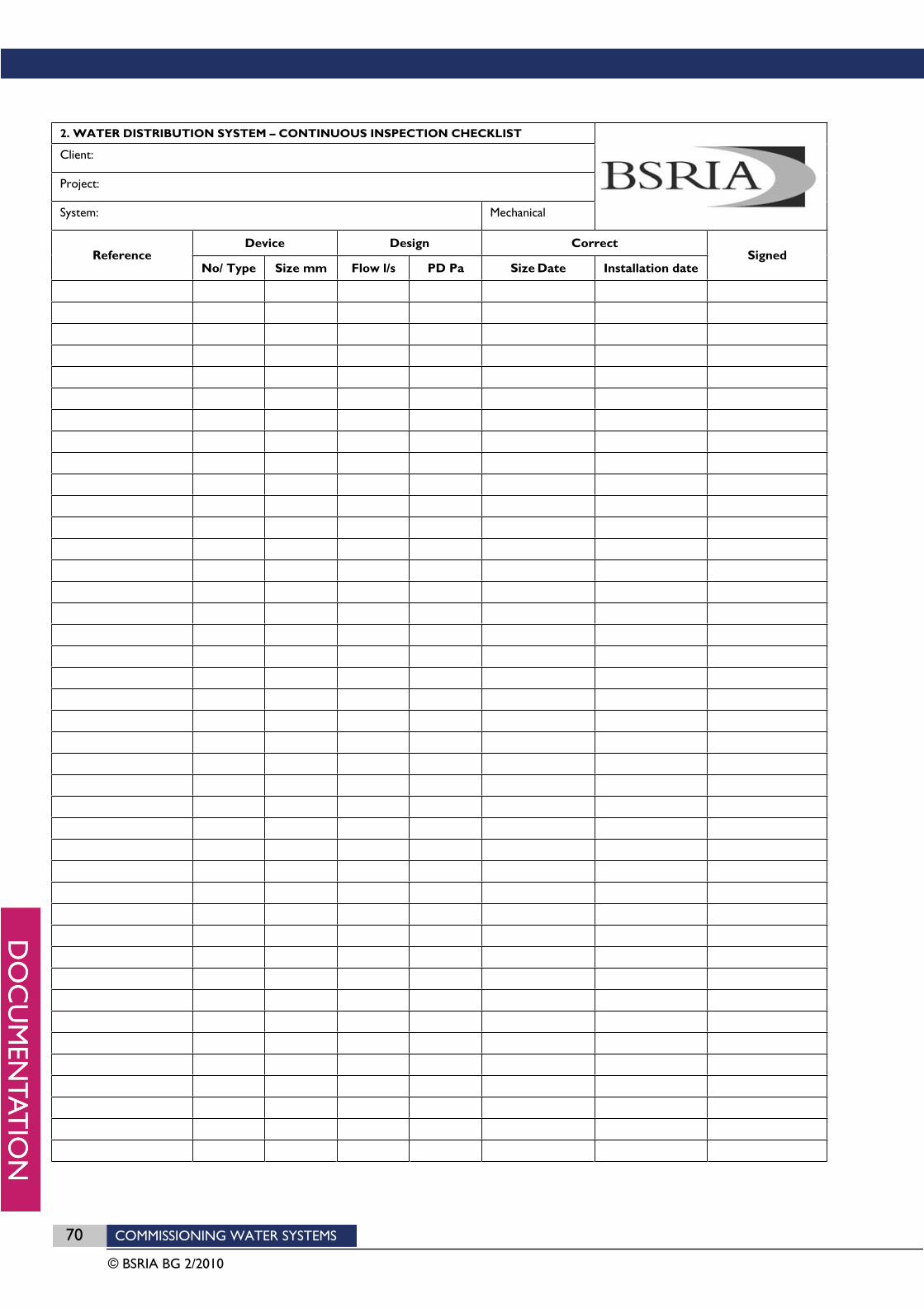
70 COMMISSIONING WATER SYSTEMS
© BSRIA BG 2/2010
2. WATER DISTRIBUTION SYSTEM – CONTINUOUS INSPECTION CHECKLIST
Client:
Project:
System: Mechanical
Device Design Correct Reference
No/ Type Size mm Flow l/s PD Pa Size Date Installation date Signed

COMMISSIONING WATER SYSTEMS 71
© BSRIA BG 2/2010
3. WATER DISTRIBUTION SYSTEM – FINAL INSPECTION CHECKLIST
Client:
Project:
System: Mechanical
Check that: / Comments / Follow-up references
1. Major plant, intermediary heat exchangers and space terminal units are installed in accordance with the specification and manufacturers’ instructions
1.
2. Pumps are installed in accordance with the specification and to manufacturers’ instructions
2.
3. Pump and valve gland packing and special valve lubricants are compatible with the specified chemical cleaning and water treatment procedures
3.
4. Permanent water connections are provided, as required 4.
5. Flow measurement devices are installed in accordance with the specification and manufacturers’ instructions
5.
6. Probe pockets, pressure gauges, syphons and test points are installed, as specified
6.
7. Manual and automatic air vents are installed, as required 7.
8. Drains, valves and overflows of appropriate size are connected and free from blockage
8.
9. Connections to heater and cooler batteries and other heat exchangers are correct in relation to the design water flow direction
9.
10. Control, double-regulating and non-return valves are installed the right way round
10.
11. Relief valves are installed in accordance with the specification and manufacturers’ instructions and are free to operate
11.
12. Relief valve outlets are piped away to suitable drain points 12.
13. Expansion devices are aligned and free from obstruction 13.
14. Strainers with the correct mesh grade and material are installed 14.
15. Changeover devices for duplex strainers are operative 15.
16. Washers, tanks, nozzles and filters are clean 16.
17. Tank covers are provided, where specified 17.
18. Drain cocks are dosed and other valves left open or dosed according to the plan for filling
18.
19. The cold feed connection is correctly located 19.
20. Pipework and fittings are adequately supported and anchored, where applicable, and in accordance with the specification
20.
21. Adequate space is provided to access equipment and system components as required
21.
GENERAL COMMENTS
Date: / / Engineer: Approved by: Sheet: /
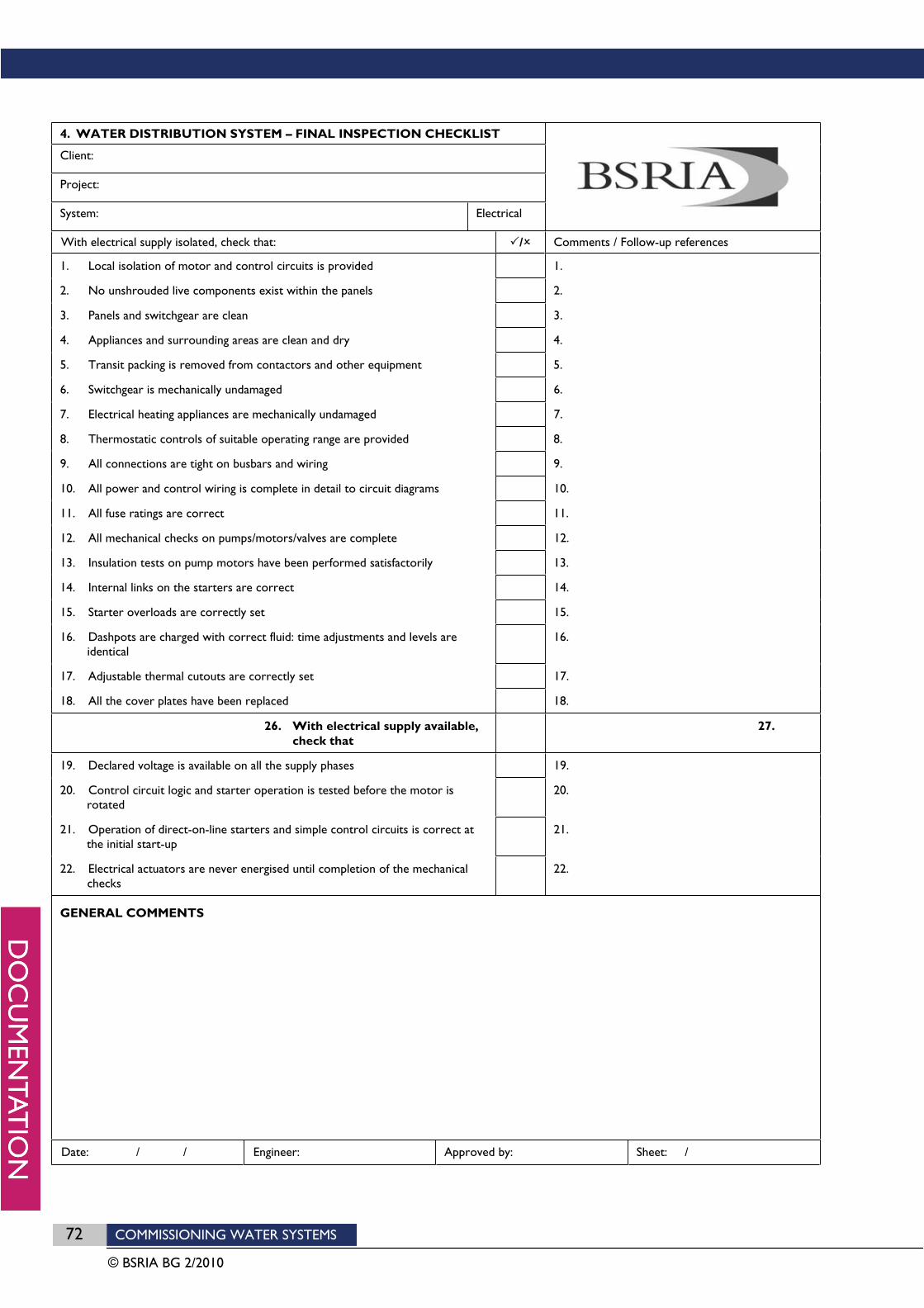
72 COMMISSIONING WATER SYSTEMS
© BSRIA BG 2/2010
4. WATER DISTRIBUTION SYSTEM – FINAL INSPECTION CHECKLIST
Client:
Project:
System: Electrical
With electrical supply isolated, check that: / Comments / Follow-up references
1. Local isolation of motor and control circuits is provided 1.
2. No unshrouded live components exist within the panels 2.
3. Panels and switchgear are clean 3.
4. Appliances and surrounding areas are clean and dry 4.
5. Transit packing is removed from contactors and other equipment 5.
6. Switchgear is mechanically undamaged 6.
7. Electrical heating appliances are mechanically undamaged 7.
8. Thermostatic controls of suitable operating range are provided 8.
9. All connections are tight on busbars and wiring 9.
10. All power and control wiring is complete in detail to circuit diagrams 10.
11. All fuse ratings are correct 11.
12. All mechanical checks on pumps/motors/valves are complete 12.
13. Insulation tests on pump motors have been performed satisfactorily 13.
14. Internal links on the starters are correct 14.
15. Starter overloads are correctly set 15.
16. Dashpots are charged with correct fluid: time adjustments and levels are identical
16.
17. Adjustable thermal cutouts are correctly set 17.
18. All the cover plates have been replaced 18.
26. With electrical supply available, check that
27.
19. Declared voltage is available on all the supply phases 19.
20. Control circuit logic and starter operation is tested before the motor is rotated
20.
21. Operation of direct-on-line starters and simple control circuits is correct at the initial start-up
21.
22. Electrical actuators are never energised until completion of the mechanical checks
22.
GENERAL COMMENTS
Date: / / Engineer: Approved by: Sheet: /

COMMISSIONING WATER SYSTEMS 73
© BSRIA BG 2/2010
5. WATER DISTRIBUTION SYSTEM – PRE-COMMISSIONING CHECKLIST
Client:
Project:
System: Mechanical
With electrical supply isolated, check that: / Comments / Follow-up references
Pipework
1. Measurement test points are suitably positioned 1.
2. System is pressure tested, watertight, chemically cleaned and thoroughly flushed
2.
3. Strainers have been cleaned and replaced 3.
4. System is filled, vented and water treatment has been applied 4.
5. Feed and expansion tank ball float valve is operational 5.
6. System pressurisation unit is operational. 6.
7. Cold feed valve is open 7.
Pumps
8. Bearings and all external parts are clean 8.
9. Components are secure, impeller is free to rotate and flow direction is correct
9.
10. Belt drive/couplings are securely aligned 10.
11. Belt drives are a matched set (where applicable), and are correctly tensioned
11.
12. Motor and pump are lubricated 12.
13. Glands are packed and adjusted to correct drip rate; gland bowl drains are fitted and clear
13.
14. Water coolant is available 14.
15. Motor and drive guards are fitted; access is available for tachometer 15.
16. Power supplies and control circuits are operational; starter overloads, fuse ratings dashpot levels and motor rotations are correct
16.
Motorised valves
17. Mountings are rigid 17.
18. Stiffness of linkages and geometry of linkages and couplings is correct 18.
19. Valve spindles are free to move 19.
20. Bearings are lubricated 20.
21. The pins fit and the locking devices are tight 21.
GENERAL COMMENTS
Date: / / Engineer: Approved by: Sheet: /
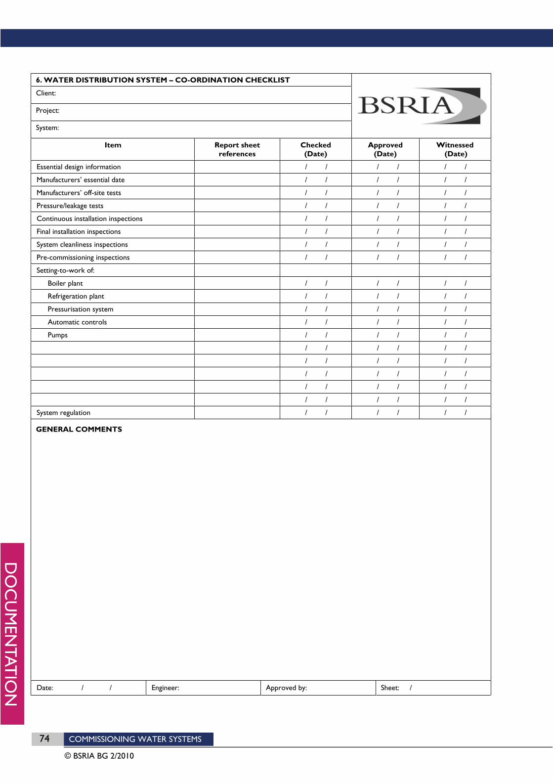
74 COMMISSIONING WATER SYSTEMS
© BSRIA BG 2/2010
6. WATER DISTRIBUTION SYSTEM – CO-ORDINATION CHECKLIST
Client:
Project:
System:
Item Report sheet references
Checked (Date)
Approved (Date)
Witnessed (Date)
Essential design information / / / / / /
Manufacturers’ essential date / / / / / /
Manufacturers’ off-site tests / / / / / /
Pressure/leakage tests / / / / / /
Continuous installation inspections / / / / / /
Final installation inspections / / / / / /
System cleanliness inspections / / / / / /
Pre-commissioning inspections / / / / / /
Setting-to-work of:
Boiler plant / / / / / /
Refrigeration plant / / / / / /
Pressurisation system / / / / / /
Automatic controls / / / / / /
Pumps / / / / / /
/ / / / / /
/ / / / / /
/ / / / / /
/ / / / / /
/ / / / / /
System regulation / / / / / /
GENERAL COMMENTS
Date: / / Engineer: Approved by: Sheet: /

COMMISSIONING WATER SYSTEMS 75
© BSRIA BG 2/2010
7. WATER DISTRIBUTION SYSTEM – SETTING-TO-WORK CHECKLIST
Client:
Project:
System: Centrifugal pump-set
Check that: / Comments / Follow-up references
Prior to pump start
1. All normally open isolating and regulating valves are fully open 1.
2. All by-pass and normally closed valves are closed 2.
3. All thermostatically controlled valves are open and not adversely affected by ambient air/water temperature
3.
4. All motorised valves are set to manual over-ride 4.
5. A method of setting pneumatically controlled valves is available 5.
6. Automatic control valves are set to full flow to heat exchangers or branch circuits
6.
7. Pump suction/return valve is fully open 7.
8. Valves isolating standby pumps are closed 8.
9. Pump casing is vented of air 9.
10. Pump discharge/flow valve is 50% closed to limit initial start current 10.
Initial Start
11. Direction and rotation speed of motor shaft is correct 11.
12. Motor, pump and drive are free from vibration and undue noise 12.
13. Motor starting current is correct for sequence timing adjustments 13.
14. Motor running current is balanced between phases 14.
15. There is no sparking at the commutator or slip rings 15.
16. Motor and bearings are not overheating and water coolant is adequate 16.
17. There is no seepage of lubricant from the housing 17.
18. Reduced speed and motor running currents are correct on multi-speed motors
18.
Initial Run
19. Fuses, switchgear and motor are not overstressed 19.
20. Motor current reaches design value or full load current, whichever is the lower
20.
21. Pump pressure developed does not exceed system design pressure 21.
Running-in Period
22. Bearings and motor temperature remain steady 22.
23. Gland nuts are adjusted to give correct drip rates 23.
24. Strainers are inspected for cleanliness 24.
State condition of strainer on completion
GENERAL COMMENTS
Date: / / Engineer: Approved by: Sheet: /
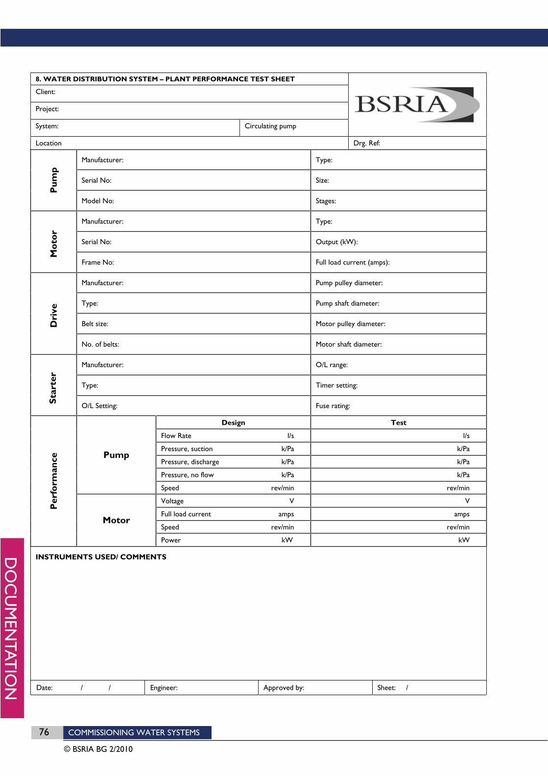
76 COMMISSIONING WATER SYSTEMS
© BSRIA BG 2/2010
8. WATER DISTRIBUTION SYSTEM – PLANT PERFORMANCE TEST SHEET
Client:
Project:
System: Circulating pump
Location Drg. Ref:
Manufacturer: Type:
Serial No: Size:
Pum
p
Model No: Stages:
Manufacturer: Type:
Serial No: Output (kW):
Mo
tor
Frame No: Full load current (amps):
Manufacturer: Pump pulley diameter:
Type: Pump shaft diameter:
Belt size: Motor pulley diameter: Dri
ve
No. of belts: Motor shaft diameter:
Manufacturer: O/L range:
Type: Timer setting:
Sta
rter
O/L Setting: Fuse rating:
Design Test
Flow Rate l/s l/s
Pressure, suction k/Pa k/Pa
Pressure, discharge k/Pa k/Pa
Pressure, no flow k/Pa k/Pa
Pump
Speed rev/min rev/min
Voltage V V
Full load current amps amps
Speed rev/mìn rev/min
Per
form
ance
Motor
Power kW kW
INSTRUMENTS USED/ COMMENTS
Date: / / Engineer: Approved by: Sheet: /
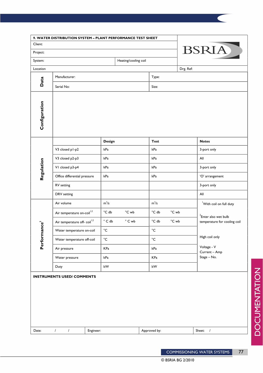
COMMISSIONING WATER SYSTEMS 77
© BSRIA BG 2/2010
9. WATER DISTRIBUTION SYSTEM – PLANT PERFORMANCE TEST SHEET
Client:
Project:
System: Heating/cooling coil
Location Drg. Ref:
Manufacturer: Type:
Dat
a
Serial No: Size:
Co
nfig
urat
ion
Design Test Notes
V3 closed p1-p2 kPa kPa 3-port only
V3 closed p2-p3 kPa kPa All
V1 closed p3-p4 kPa kPa 3-port only
Office differential pressure kPa kPa ‘O’ arrangement
RV setting 3-port only
Reg
ulat
ion
DRV setting All
Air volume m3/s m3/s
Air temperature on-coil1,2 °C db °C wb °C db °C wb
Air temperature off- coil1,2 ° C db ° C wb °C db °C wb
Water temperature on-coil °C °C
Water temperature off-coil °C °C
Air pressure KPa kPa
Water pressure kPa KPa
Per
form
ance
2
Duty kW kW
1With coil on full duty
2Enter also wet bulb
temperature for cooling coil
High coil only
Voltage - V Current – Amp Stage – No.
INSTRUMENTS USED/ COMMENTS
Date: / / Engineer: Approved by: Sheet: /

78 COMMISSIONING WATER SYSTEMS
© BSRIA BG 2/2010
10. WATER DISTRIBUTION SYSTEM – WATER BALANCE TEST SHEET
Client:
Project:
System: Circulating pump
Valve1 Design2 Test results2 Notes
No. Type Size Location Vol Kv p Initial Final
p Vol %D p Vol %D VPos
INSTRUMENTS USED/COMMENTS 1 OV - Orifice valve DR - Double-regulating valve CV - Control valve
2 %D - % Design Vpos - Valve position Size - mm Vol - l/s Kv - m3/h @ 1 bar
p - kPa
Date: / / Engineer: Approved by: Sheet: /
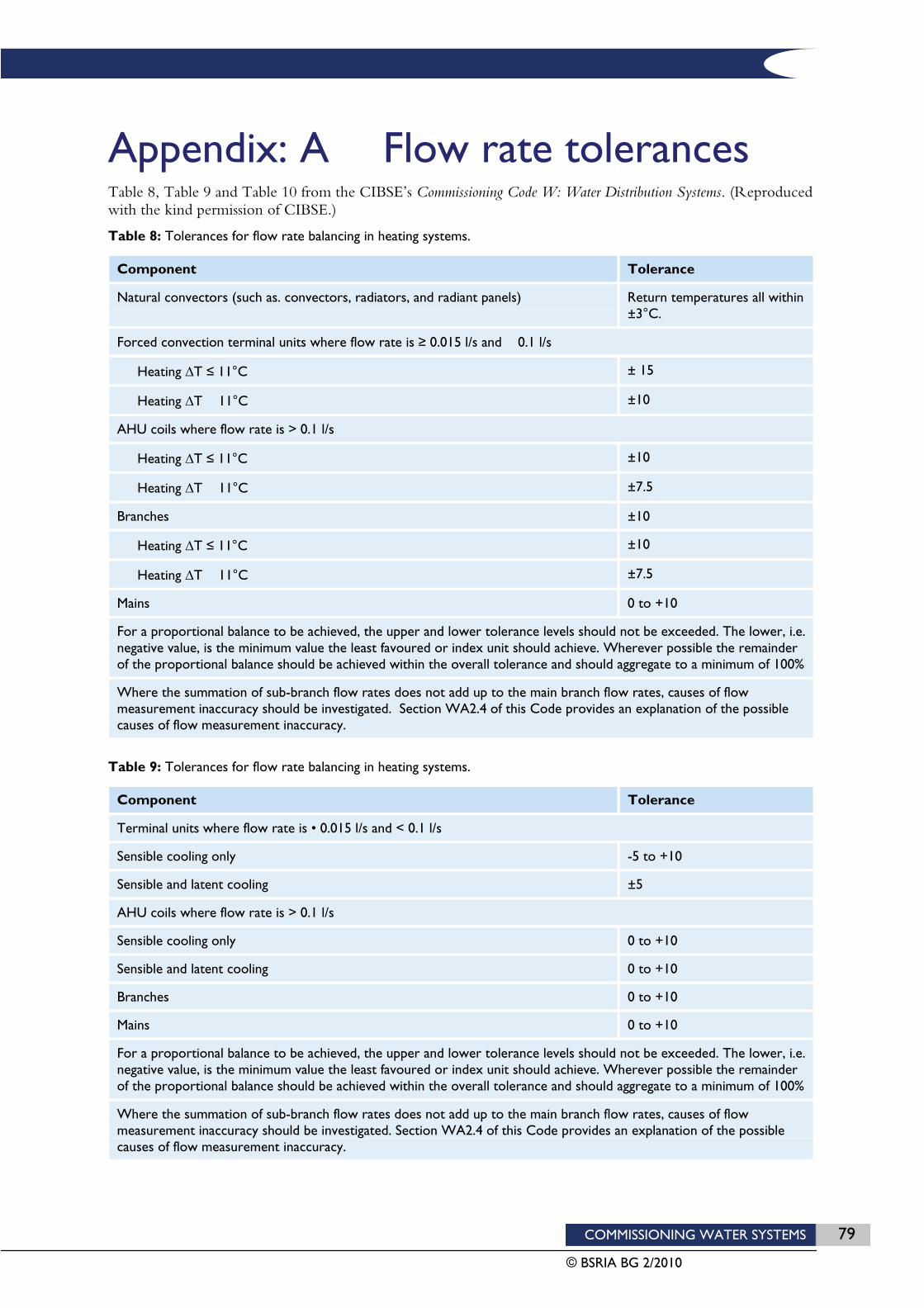
COMMISSIONING WATER SYSTEMS 79
© BSRIA BG 2/2010
Appendix: A Flow rate tolerances Table 8, Table 9 and Table 10 from the CIBSE’s Commissioning Code W: Water Distribution Systems. (Reproduced with the kind permission of CIBSE.)
Table 8: Tolerances for flow rate balancing in heating systems.
Component Tolerance
Natural convectors (such as. convectors, radiators, and radiant panels) Return temperatures all within ±3°C.
Forced convection terminal units where flow rate is 0.015 l/s and 0.1 l/s
Heating T 11°C ± 15
Heating T 11°C ±10
AHU coils where flow rate is > 0.1 l/s
Heating T 11°C ±10
Heating T 11°C ±7.5
Branches ±10
Heating T 11°C ±10
Heating T 11°C ±7.5
Mains 0 to +10
For a proportional balance to be achieved, the upper and lower tolerance levels should not be exceeded. The lower, i.e. negative value, is the minimum value the least favoured or index unit should achieve. Wherever possible the remainder of the proportional balance should be achieved within the overall tolerance and should aggregate to a minimum of 100%
Where the summation of sub-branch flow rates does not add up to the main branch flow rates, causes of flow measurement inaccuracy should be investigated. Section WA2.4 of this Code provides an explanation of the possible causes of flow measurement inaccuracy.
Table 9: Tolerances for flow rate balancing in heating systems.
Component Tolerance
Terminal units where flow rate is • 0.015 l/s and < 0.1 l/s
Sensible cooling only -5 to +10
Sensible and latent cooling ±5
AHU coils where flow rate is > 0.1 l/s
Sensible cooling only 0 to +10
Sensible and latent cooling 0 to +10
Branches 0 to +10
Mains 0 to +10
For a proportional balance to be achieved, the upper and lower tolerance levels should not be exceeded. The lower, i.e. negative value, is the minimum value the least favoured or index unit should achieve. Wherever possible the remainder of the proportional balance should be achieved within the overall tolerance and should aggregate to a minimum of 100%
Where the summation of sub-branch flow rates does not add up to the main branch flow rates, causes of flow measurement inaccuracy should be investigated. Section WA2.4 of this Code provides an explanation of the possible causes of flow measurement inaccuracy.
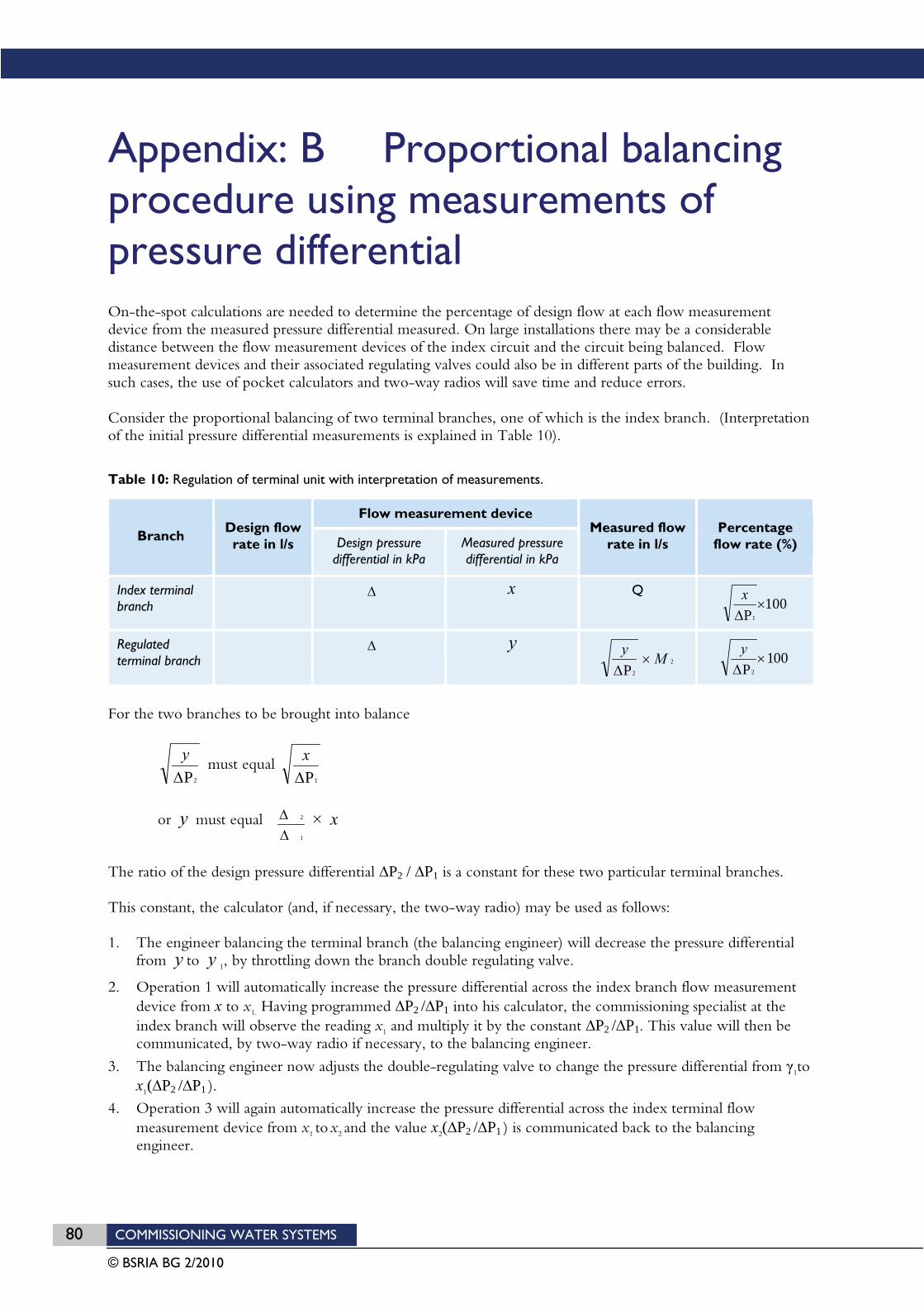
80 COMMISSIONING WATER SYSTEMS
© BSRIA BG 2/2010
Appendix: B Proportional balancing procedure using measurements of pressure differential On-the-spot calculations are needed to determine the percentage of design flow at each flow measurement device from the measured pressure differential measured. On large installations there may be a considerable distance between the flow measurement devices of the index circuit and the circuit being balanced. Flow measurement devices and their associated regulating valves could also be in different parts of the building. In such cases, the use of pocket calculators and two-way radios will save time and reduce errors.
Consider the proportional balancing of two terminal branches, one of which is the index branch. (Interpretation of the initial pressure differential measurements is explained in Table 10).
Table 10: Regulation of terminal unit with interpretation of measurements.
Flow measurement device
BranchDesign flow rate in l/s Design pressure
differential in kPa Measured pressure differential in kPa
Measured flow rate in l/s
Percentageflow rate (%)
Index terminal branch
x Q100
P1
x
Regulatedterminal branch
y2
2PMy 001
P2
y
For the two branches to be brought into balance
2Py
must equal1Px
or y must equal1
2 × x
The ratio of the design pressure differential P2 / P1 is a constant for these two particular terminal branches.
This constant, the calculator (and, if necessary, the two-way radio) may be used as follows:
1. The engineer balancing the terminal branch (the balancing engineer) will decrease the pressure differential from y to y 1, by throttling down the branch double regulating valve.
2. Operation 1 will automatically increase the pressure differential across the index branch flow measurement device from x to x1. Having programmed P2 / P1 into his calculator, the commissioning specialist at the index branch will observe the reading x1 and multiply it by the constant P2 / P1. This value will then be communicated, by two-way radio if necessary, to the balancing engineer.
3. The balancing engineer now adjusts the double-regulating valve to change the pressure differential from 1tox1( P2 / P1 ).
4. Operation 3 will again automatically increase the pressure differential across the index terminal flow measurement device from x1 tox2 and the value x2( P2 / P1 ) is communicated back to the balancing engineer.

COMMISSIONING WATER SYSTEMS 81
© BSRIA BG 2/2010
5. The process is repeated with the balancing engineer making finer and finer adjustments until a stable balanced state is achieved.
6. Having completed the above operations, the balancing engineer moves on to the next terminal branch; the index engineer establishes the new design pressure differential ratio and keys this constant into his calculator, and the whole process is repeated.
With experience and the application of intelligent anticipation, this procedure may be speedily and systematically carried out with the objective of achieving zero deviation from the target percentage design flow. The terminal branches closest to the index branch generally require greater care and attention because their adjustment has a much greater influence on the flow rate through the index branch.

82 COMMISSIONING WATER SYSTEMS
© BSRIA BG 2/2010
Related Documents