SECONDARY SUBSTATION INSTALLATION AND COMMISSIONING SPECIFICATION SUB-02-006 Issue No. 5 ___________________________________________________________________________ © SP Power Systems Limited Page 1 of 32 1. SCOPE This document outlines EnergyNetworks installation and commissioning specification for ground mounted secondary substations and includes all transformer substations where the lower voltage is 400/230V. 2. ISSUE RECORD This is a controlled maintained document. All copies printed via the Intranet or photocopied will be deemed uncontrolled. Issue Date Issue No Author Amendment Details January 07 5 A.Graham LSOH cables and Midel requirements added, civil requirements changed, Protection commissioning updated. October 05 4 I.McFadyen Door specification revised in section 8.8 June 04 3 A.Graham Minor revisions 3. ISSUE AUTHORITY Author Owner Issue Authority Alastair Graham Policy and Standards Manager Alastair Graham Policy and Standards Manager Carl Woodman Engineering Services Manager ………………….. 4. REVIEW This document shall be subject to periodic review as and when required.

commissioning substation scotish.pdf
Oct 21, 2015
Welcome message from author
This document is posted to help you gain knowledge. Please leave a comment to let me know what you think about it! Share it to your friends and learn new things together.
Transcript

SECONDARY SUBSTATION INSTALLATION AND
COMMISSIONING SPECIFICATION
SUB-02-006 Issue No. 5
___________________________________________________________________________ © SP Power Systems Limited Page 1 of 32
1. SCOPE
This document outlines EnergyNetworks installation and commissioning specification for ground mounted secondary substations and includes all transformer substations where the lower voltage is 400/230V.
2. ISSUE RECORD
This is a controlled maintained document. All copies printed via the Intranet or photocopied will be deemed uncontrolled. Issue Date Issue No Author Amendment Details
January 07 5 A.Graham LSOH cables and Midel requirements added, civil requirements changed, Protection commissioning updated.
October 05 4 I.McFadyen Door specification revised in section 8.8
June 04 3 A.Graham Minor revisions
3. ISSUE AUTHORITY
Author Owner Issue Authority Alastair Graham Policy and Standards Manager
Alastair Graham Policy and Standards Manager
Carl Woodman Engineering Services Manager …………………..
4. REVIEW
This document shall be subject to periodic review as and when required.
SECONDARY SUBSTATION INSTALLATION AND
COMMISSIONING SPECIFICATION
SUB-02-006 Issue No. 5
___________________________________________________________________________ © SP Power Systems Limited Page 2 of 32
5. CONTENTS
1. SCOPE ......................................................................................................................................................... 1
2. ISSUE RECORD......................................................................................................................................... 1
3. ISSUE AUTHORITY ................................................................................................................................. 1
4. REVIEW...................................................................................................................................................... 1
5. CONTENTS................................................................................................................................................. 2
6. GLOSSARY................................................................................................................................................. 4
7. RELATED DOCUMENTS ........................................................................................................................ 6
8. GENERAL REQUIREMENTS ................................................................................................................. 7 8.1 APPROVED EQUIPMENT ........................................................................................................................ 7 8.2 ENCLOSURES ........................................................................................................................................ 7 8.3 ACCESS/EGRESS................................................................................................................................... 9 8.4 LAND REQUIREMENTS.......................................................................................................................... 9 8.5 EARTHING ............................................................................................................................................ 9 8.6 LABELLING........................................................................................................................................... 9 8.7 SUBSTATION LV SERVICES .................................................................................................................. 9 8.8 IDNO INTERFACE SUBSTATIONS ....................................................................................................... 10 8.9 ENERGYNETWORKS REQUIREMENTS FOR SUBSTATIONS INSTALLED WITHIN CUSTOMER OWNED/PUBLICLY OCCUPIED BUILDINGS.......................................................................................................... 11 8.10 EMBEDDED GENERATION ................................................................................................................... 12 8.11 CIVIL WORKS...................................................................................................................................... 12 8.12 CABLING ............................................................................................................................................ 12
9. UNIT SUBSTATIONS.............................................................................................................................. 13 9.1 ENCLOSURE........................................................................................................................................ 13
10. ‘X’ TYPE - NON-UNIT SUBSTATIONS .......................................................................................... 14 10.1 ENCLOSURE........................................................................................................................................ 14 10.2 SUBSTATION LV SERVICES ................................................................................................................ 14 10.3 ASSOCIATED DRAWINGS .................................................................................................................... 14
11. INDUSTRIAL HV CUSTOMER RMU SUBSTATIONS................................................................. 15 11.1 ENCLOSURE........................................................................................................................................ 15 11.2 METERING.......................................................................................................................................... 16
12. INDUSTRIAL LV CUSTOMER SUBSTATIONS............................................................................ 17 12.1 ENCLOSURE........................................................................................................................................ 17 12.2 METERING.......................................................................................................................................... 17
13. HV CUSTOMER SWITCHBOARD SUBSTATION........................................................................ 18 13.1 ENCLOSURE........................................................................................................................................ 18 13.2 SUBSTATION LV SERVICES ................................................................................................................ 18 13.3 EMERGENCY HV DISCONNECTION..................................................................................................... 18

SECONDARY SUBSTATION INSTALLATION AND
COMMISSIONING SPECIFICATION
SUB-02-006 Issue No. 5
___________________________________________________________________________ © SP Power Systems Limited Page 3 of 32
14. COMMISSIONING ............................................................................................................................. 19 14.1 VISUAL INSPECTION ........................................................................................................................... 19 14.2 MECHANICAL TESTING....................................................................................................................... 19 14.3 PROTECTION TESTING ........................................................................................................................ 20
14.3.1 Enhanced Protection Commissioning ...................................................................................... 20 14.3.2 Standard Protection Commissioning ....................................................................................... 21 14.3.3 IDNO Protection Commissioning ............................................................................................ 21
14.4 ELECTRICAL INSULATION TESTING .................................................................................................... 21 14.5 PRE-ENERGISATION CHECKS.............................................................................................................. 21
APPENDIX 1– DIAGRAMS ............................................................................................................................. 22 Figure 1 – Typical site Layout for a Unit Substation................................................................................ 23 Figure 2 – Typical Layout for a ‘X’ Type Substation ............................................................................... 24 Figure 3 – Typical Layout for an Industrial HV Customer Substation ................................................... 25 Figure 4 – Typical Layout for an Industrial LV Customer Substation .................................................... 26 Figure 5 – Typical Layout for an Industrial HV Switching Substation ................................................... 27
APPENDIX 2 – DRAWING REGISTER......................................................................................................... 28
APPENDIX 3 - EQUIPMENT CHECK LIST ................................................................................................. 29 SWITCHGEAR.................................................................................................................................................... 29 TRANSFORMERS (1000KVA AND BELOW) ........................................................................................................ 30 LV EQUIPMENT ................................................................................................................................................ 30
APPENDIX 4 - SUBSTATION COMMISSIONING PROGRESS CARD ................................................... 31 VISUAL INSPECTION ......................................................................................................................................... 31 MECHANICAL TESTING..................................................................................................................................... 31 PROTECTION TESTING ...................................................................................................................................... 32 ELECTRICAL INSULATION TESTING................................................................................................................... 32 PRE-ENERGISING CHECKS ................................................................................................................................ 32
SECONDARY SUBSTATION INSTALLATION AND
COMMISSIONING SPECIFICATION
SUB-02-006 Issue No. 5
___________________________________________________________________________ © SP Power Systems Limited Page 4 of 32
6. GLOSSARY
For the purpose of this document the following definitions shall apply: Approved: Equipment which is Approved in accordance with
EnergyNetworks documents for use or installation on the Company network.
Company: Refers to SP Distribution Ltd, SP Transmission Ltd and SP
Manweb plc. Equipment: Switchgear, transformers, cables, overhead lines, surge
arresters, voltage transformers, current transformers, unit substations.
Energisation: The application of Voltage to an item(s) of Equipment from the
system. High Voltage: An AC voltage exceeding 1000 volts measured between the
phase conductors. IDNO’s: Independent Distribution Network Operator ICP: Independent Connections Provider: Suitably Lloyds/National
Electrical Registration Scheme - Accredited Contractors undertaking contestable work in the competitive connections market.
Indoor Equipment: Equipment designed solely for installation within a building or
other housing where the Equipment is protected against wind, rain, snow, abnormal dirt deposits, abnormal condensation and frost.
Low Voltage: An AC voltage not exceeding 1000 volts measured between the
phase conductors. LSOH: Low Smoke Zero Halogen – cables with this type of sheath
have an enhanced fire performance characteristic. Midel Midel is a synthetic ester based transformer insulating fluid
with enhanced fire performance characteristics. New: Approved Equipment which has not previously been connected
to the system and which has been routine tested in a
SECONDARY SUBSTATION INSTALLATION AND
COMMISSIONING SPECIFICATION
SUB-02-006 Issue No. 5
___________________________________________________________________________ © SP Power Systems Limited Page 5 of 32
Manufacturing Facility with a Quality Management System in accordance with the relevant standard prior to delivery.
EnergyNetworks: SP PowerSystems Ltd, operator of network assets on behalf of
the Company. Previously In Service: Equipment which, has previously been connected to the
Company system and is deemed suitable for re-use in accordance with ASSET-01-010, and has been electrically tested prior to site in accordance with SUB-02-613 where appropriate.
Secondary substation: An assembly of High Voltage Switchgear, Transformers and
LV Switchgear in an enclosure where the lower voltage is 400/230V.
Second Hand: Equipment which has previously been energised outwith the
Company network.
SP Distribution Ltd The Distribution Licence Holder for the distribution service area formally known as ScottishPower.
SP Transmission Ltd The Transmission Licence Holder for the transmission service
area formally known as ScottishPower. SP Manweb plc The Distribution Licence Holder for the distribution service are
formally known as Manweb. Switching Station: A secondary substation containing only High Voltage Switchgear. Unit substation: A Unit substation comprises an 11kV/400V transformer fitted
with a directly mounted ring main unit and an LV fuse cabinet. Other combinations of directly mounted attachments to the transformer may also be used (e.g. cable box in lieu of HV switchgear or LV fuse cabinet.)
SECONDARY SUBSTATION INSTALLATION AND
COMMISSIONING SPECIFICATION
SUB-02-006 Issue No. 5
___________________________________________________________________________ © SP Power Systems Limited Page 6 of 32
7. RELATED DOCUMENTS
It is important that users of the documents listed below ensure that they are in possession of the latest issues of the documents together with any amendments. Statuatory Legislation ESQ&C regulations The Electricity Safety Quality and Continuity Regulations 2002 EnergyNetworks SUB-02-613 Electrical Insulation Testing of HV Equipment up to 33kV EPS-01-004 Policy for Signing and Guarding of Electrical Network Apparatus CAB-15-003 Handling and Installation of Cables up to and including 33kV CAB-04-009 Policy and Application Guide for 11kV Polymeric Cables DOC-00-280 Approved Equipment Register Index EART-02-003 Earthing and Bonding at Secondary Substations ASSET-01-010 EnergyNetworks Equipment Reuse Policy ESDD-02-012 Design and Planning Framework for Greenfield Low Voltage
Housing Estates Installations and Associated HV/LV Distribution Substations
GEN-01-001 Policy for the Connection of Embedded Generation SUB-03-017 General Specification for the Civil Engineering and Building Design
and Construction of Secondary Substations. SUB-02-013 Policy and Specification for the Interface with Independent
Distribution Network Operators Installations
SECONDARY SUBSTATION INSTALLATION AND
COMMISSIONING SPECIFICATION
SUB-02-006 Issue No. 5
___________________________________________________________________________ © SP Power Systems Limited Page 7 of 32
8. GENERAL REQUIREMENTS
8.1 Approved Equipment
Only New Approved Equipment as detailed within the EnergyNetworks Approved Equipment Register, DOC-00-280, or Previously in Service Equipment as detailed in ASSET-01-010 shall be installed on the Company network. Second Hand equipment shall not be installed, unless formal written approval has been given by the Engineering Services manager or his nominated representative. EnergyNetworks policy is to adopt only New Approved Equipment from ICP undertaking contestable work. Second Hand Equipment shall not be adopted.
8.2 Enclosures
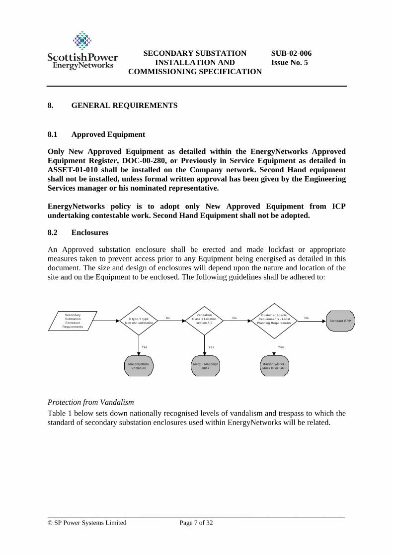
An Approved substation enclosure shall be erected and made lockfast or appropriate measures taken to prevent access prior to any Equipment being energised as detailed in this document. The size and design of enclosures will depend upon the nature and location of the site and on the Equipment to be enclosed. The following guidelines shall be adhered to:
Protection from Vandalism Table 1 below sets down nationally recognised levels of vandalism and trespass to which the standard of secondary substation enclosures used within EnergyNetworks will be related.
SecondarySubstationEnclosure
Requirements
Masonry/BrickEnclosure
X type,Y type Non unit substation
Yes
NoVandalism
Class 1 Locationsection 8.2
NoStandard GRP
Metal - Masonry/Brick
Yes
Customer SpecialRequirements - Local
Planning Requirements
Marsonry/Brick -Mock Brick GRP
Yes
No

SECONDARY SUBSTATION INSTALLATION AND
COMMISSIONING SPECIFICATION
SUB-02-006 Issue No. 5
___________________________________________________________________________ © SP Power Systems Limited Page 8 of 32
Table 1 Vandalism Child Trespass
Class 1 Very High. Location with history of frequent determined vandalism. High risk of damage to apparatus, loss of supply or dangerous situation. Risk of organised/ knowledgeable attack. Tools/ implements brought to site. Local residents indifferent/ contributory
Class 2 High. Vandalism and theft opportunist. No evidence of premeditation. Use of fortuitously available implements. Building/ enclosure bears brunt of damage. Regular need for repairs to enclosure. Local residents unlikely to assist in control.
Class 3 Medium. Occasional, irregular attacks, mostly directed at building/enclosure. Attempted interference with apparatus. Reasonably conspicuous location. Limited reporting from public.
High. Located in area with high number of children/young persons. Adjacent/nearby school, play area or regular haunt. Extensive graffiti inside enclosure, or similar evidence of trespass. Frequent damage to lightweight fencing, interference but not forcing of locks.
Class 4 Low. Infrequent incidents, graffiti, unsuccessful attempts to break locks.
Medium. Children/young persons in vicinity or on route to school or play area. Graffiti mostly external with minor damage to lightweight fences.
Class 5 Very Low. Very minor damage, mostly to vulnerable elements, chain link/timber fences. Graffiti and rubbish.
Low. Few Children in vicinity. Element of responsible public interest. Occasional graffiti on external surfaces. Only superficial damage to enclosure
Class 6 Negligible. Remote or inaccessible location. Other factors precluding vandalism.
Negligible. Remote or inaccessible site or other factors preventing trespass.
Substations which fall into Class 1 locations shall be constructed with a galvanised steel enclosure or masonry/brick enclosure as agreed on a site by site basis. Substations which fall into Class 2, 3, 4, 5 and 6 locations, shall be constructed with a G.R.P enclosure, except for ‘X’-type, ‘Y’-type non unit and Industrial HV Switching substations which shall only be installed in a suitable masonry/brick built weatherproof enclosure. The following deviations from the above policy on enclosures may be applied at the discretion of PowerSytems: • Customer Special Requirements - Where a customer requests a Masonry/Brick
constructed enclosure in lieu of a standard GRP enclosure then this shall only be installed after the customer has contractually agreed to pay for the additional costs associated with this type of enclosure.

SECONDARY SUBSTATION INSTALLATION AND
COMMISSIONING SPECIFICATION
SUB-02-006 Issue No. 5
___________________________________________________________________________ © SP Power Systems Limited Page 9 of 32
• Local Planning Requirements - Where Local Planning requires a Brick fascia enclosure, then a mock brick GRP enclosure shall be installed. Where this is deemed unacceptable by the Local Planning department formally in writing, then subsequent to a site assessment by EnergyNetworks a Masonry/brick enclosure may be installed.
Substations which are proposed to be constructed with a Masonry/brick enclosure or any other non approved enclosure at EnergyNetworks expense and fall outwith the guidelines detailed above, shall only be installed after formal written approval has been given by the Engineering and Transmission Operations Manager or his nominated representative.
8.3 Access/Egress
The substation shall have suitable 24 hour access/egress for EnergyNetworks Authorised personnel. In addition, the substation shall have suitable 24 hour street-level vehicular access/egress for Company Equipment, in line with section 9.5 of EnergyNetworks document ESDD-02-012 and SUB-03-017.
8.4 Land Requirements
All enclosures shall have a 1 metre gap between all sides and the site boundary. Wherever possible or unless required for expected future extensions, the area of the site purchased should be the minimum required. Additional areas of land are costly to maintain and serve no useful purpose to the Company.
8.5 Earthing
The earth leads from the HV steelwork earth terminal and from the LV system neutral earth terminal shall be installed as per EnergyNetworks document EART-02-003.
8.6 Labelling
Safety signs and notices shall be fitted in accordance with EnergyNetworks document EPS-01-004 and as detailed on the appropriate civil drawings. A treatment for electric shock notice shall be fitted in an appropriate position.
8.7 Substation LV Services
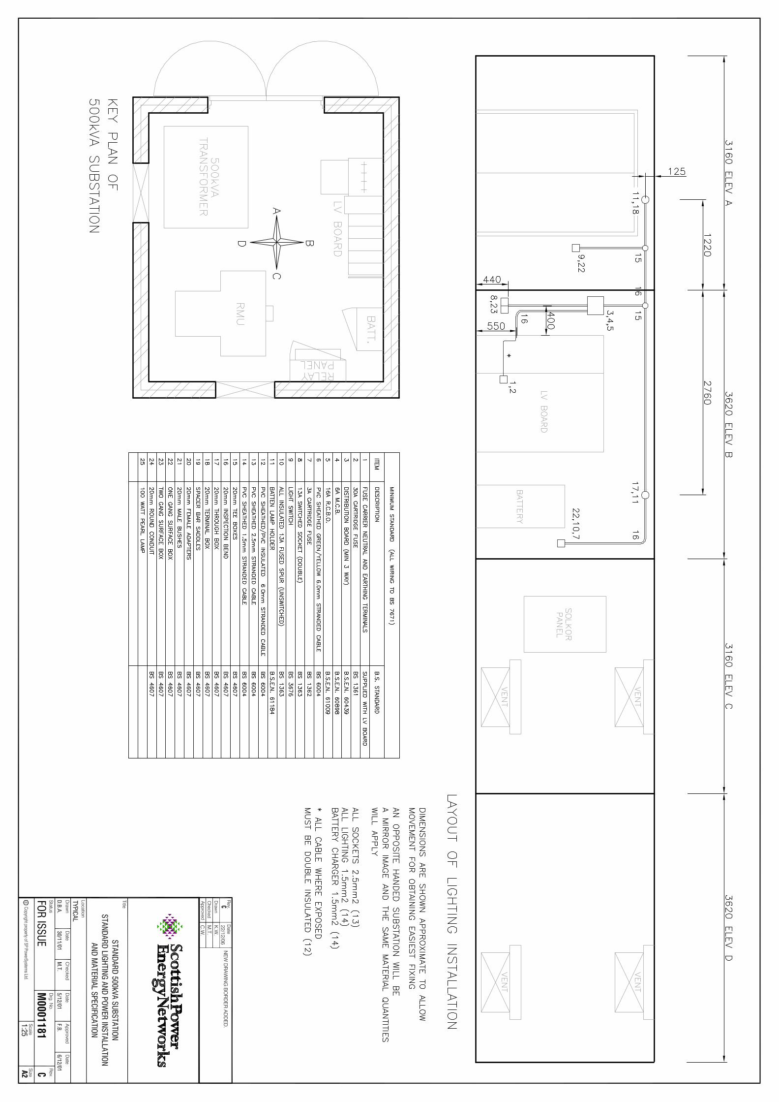
Where required by this specification, Masonry/brick enclosures or Customer owned buildings shall have suitable LV services (heating, lighting and small power) installed as detailed on drawing M0001181 and shall comply with BS7671(IEE wiring regulations) where appropriate. When LV services are being installed by an ICP a BS7671 “Electrical Installation Certificate” shall be provided at the point of adoption certifying that the LV services are BS7671 compliant.

SECONDARY SUBSTATION INSTALLATION AND
COMMISSIONING SPECIFICATION
SUB-02-006 Issue No. 5
___________________________________________________________________________ © SP Power Systems Limited Page 10 of 32
8.8 IDNO Interface Substations
Where the Company network interfaces with an IDNO, this shall be undertaken in accordance with SUB-02-013.
SECONDARY SUBSTATION INSTALLATION AND
COMMISSIONING SPECIFICATION
SUB-02-006 Issue No. 5
___________________________________________________________________________ © SP Power Systems Limited Page 11 of 32
8.9 EnergyNetworks Requirements for substations installed within Customer owned/Publicly occupied buildings
The implementation of the CDM regulations has placed a requirement for the Designer to consider the technical risks when new network assets are being installed. Consequently, EnergyNetworks preferred option when determining the location of secondary substations is for standalone, discrete sites away from buildings with public occupancy. Where it is considered necessary by the customer and has been appropriately agreed with EnergyNetworks, Secondary substations may be installed within a customer owned building. The appropriate risk assessment shall be undertaken by the Designer to ensure that all risks associated with the secondary substation are considered and mitigated to an appropriately low level. At all times, unless otherwise agreed in writing by the Engineering Services Manager or his nominated representative, the following engineering requirements shall be complied with: • EnergyNetworks civil engineering requirements, detailed within section 8.11 shall be
adhered with. Particular attention shall be given by the civil engineering designer to the risks associated with live secondary substation equipment in the building design.
• Secondary substation transformers installed within Customer owned/publicly occupied buildings shall be installed with ‘Midel’ oil.
• Company cables installed within Customer owned/Publicly occupied buildings shall be of an approved LSOH sheathed design & comply with section 8.12.
In addition: • The minimum spatial envelope shall be no less than that indicated on the appropriate
EnergyNetworks drawing detailed within this document & SUB-03-017. In addition no single dimension shall be less than that indicated within the appropriate drawing. Where other dimensions are offered by the customer/developer this shall be by negotiation with EnergyNetworks on a site by site basis.
• The substation shall have suitable 24 hour access/egress for EnergyNetworks Authorised personnel.
• The substation shall have suitable 24 hour street-level vehicular access/egress for Company Equipment, in line with section 9.5 of EnergyNetworks document ESDD-02-012.
• Where High/Low voltage Indoor Switchgear is utilised it shall be installed in a suitable building with a controlled environment to ensure compliance with clause 2.1 of IEC 60694 for class “minus 5 indoor”.
• Sufficient ventilation shall be provided to ensure that the ambient temperature does not exceed 30°C, for losses of 14kW for a 1000kVA transformer and 9kW for a 500kVA transformer.
• Suitable means of access shall be provided to Company cables installed within the Customers building.
SECONDARY SUBSTATION INSTALLATION AND
COMMISSIONING SPECIFICATION
SUB-02-006 Issue No. 5
___________________________________________________________________________ © SP Power Systems Limited Page 12 of 32
• Appropriate building services shall be made available to facilitate heating, lighting and small power, as per section 8.7.
8.10 Embedded Generation
All embedded generation installations and associated connections to the Company’s network shall comply with the requirements of the ESQC regulations, the appropriate Engineering Recommendations and the specific requirements of EnergyNetworks policy GEN-01-001.
8.11 Civil works
All secondary substations civil and structural designs shall be installed in accordance with EnergyNetworks specification SUB-03-017. All Civil Engineering drawings referenced in this document can be found in EnergyNetworks specification SUB-03-017.
8.12 Cabling
All cables connecting substation Equipment to the Company network, shall be installed in accordance with EnergyNetworks specification CAB-15-003 and CAB-04-009.
SECONDARY SUBSTATION INSTALLATION AND
COMMISSIONING SPECIFICATION
SUB-02-006 Issue No. 5
___________________________________________________________________________ © SP Power Systems Limited Page 13 of 32
9. UNIT SUBSTATIONS
This section covers the requirements for Unit type substations installed on the Company network. The general layout of the standard GRP unit substation is shown in Figure 1, Appendix 2. A Unit substation comprises of the following Equipment: • 11kV/433V (Dual ratio 11kV/6.6kV/433V where appropriate) Transformer (500kVA,
1MVA rating) • Transformer mounted 400V fuse cabinet, 1600A busbars, 5 way, 93mm centre fuses • Transformer mounted 11kV Ring Main Unit Other combinations of directly mounted attachments to the transformer (e.g. cable box in lieu of HV switchgear or LV fuse cabinet) shall only be installed where formal written approval has been given by the Engineering and Transmission Operations Manager, or his nominated representative.
9.1 Enclosure
An Approved prefabricated GRP enclosure shall be the preferred means of installation in compliance with section 8.2. The dimensions and construction of the GRP enclosed Unit substation shall be as shown on EnergyNetworks drawing SP2022244 detailed in SUB-03-017. Where required by section 8.2, a masonry/brick or galvanised steel enclosure shall be constructed as shown in EnergyNetworks drawings SP3020357 detailed in SUB-03-017. Unit substations which are proposed to be constructed with a Masonry/brick enclosure or any other non approved enclosure at EnergyNetworks expense and fall outwith the guidelines detailed in section 8.2, shall only be installed after formal written approval has been given by the Engineering Services manager or his nominated representative.

SECONDARY SUBSTATION INSTALLATION AND
COMMISSIONING SPECIFICATION
SUB-02-006 Issue No. 5
___________________________________________________________________________ © SP Power Systems Limited Page 14 of 32
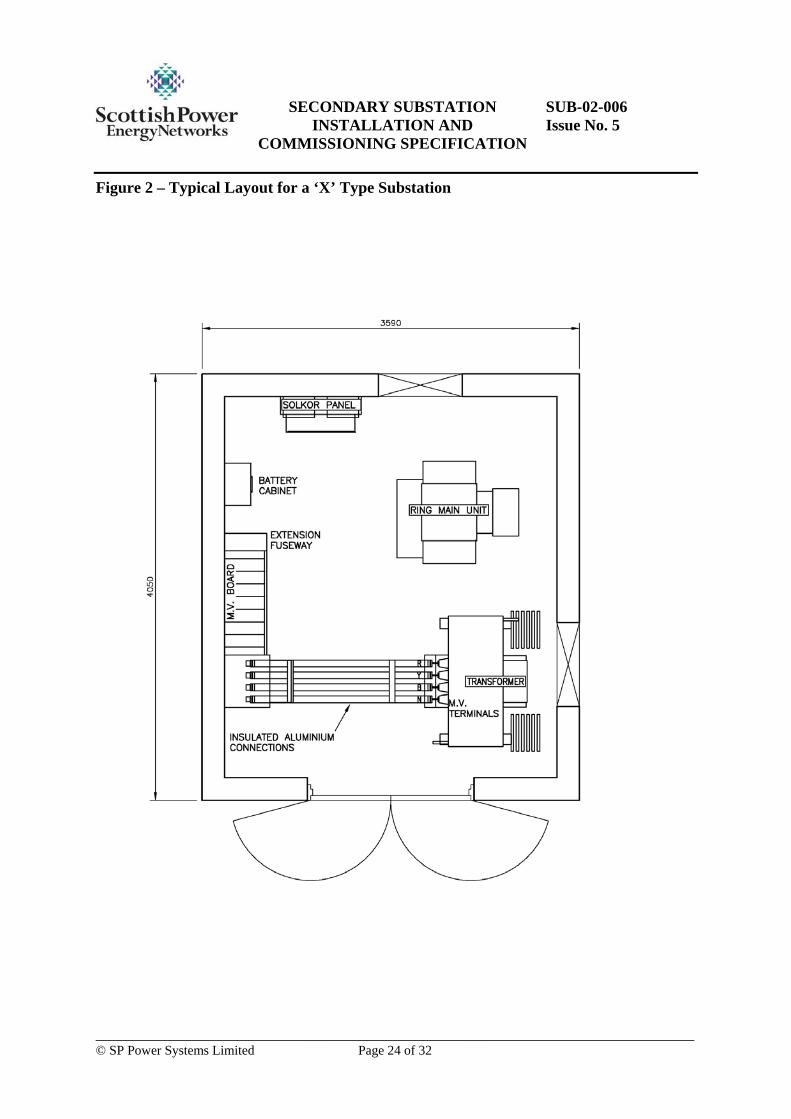
10. ‘X’ TYPE - NON-UNIT SUBSTATIONS
This particular type of substation is unique to the SP Manweb network area and are technically complex, utilising pilot wire protection more typically found in Primary substations. The general layout of the site shall be as per Figure 2. EnergyNetworks recommend that ICP’s undertaking contestable work contact EnergyNetworks to discuss the significant technical issues prior to commencing the design, procurement or installation of an ‘X’ Type – Non Unit substation. An ‘X’ type substation comprises of the following Equipment: • 11kV/433V “tall” Transformer (500kVA rating) • Free standing X type 11kV Ring Main Unit (fully rated T off earth switch) • Wall mounted 400V fuse cabinet (Type ‘A’) • Wall Mounted Solkor Protection Panel • Battery and Charger
10.1 Enclosure
This particular type of substation contains Indoor Equipment which requires to be installed in a suitable permanent brick built enclosure. The enclosure shall be of a masonry/brick construction to the general construction shown in Figure 2 for the Unit Substation, with the details of construction and foundations given in EnergyNetworks Drawing SP4000545 as detailed in SUB-03-017. NOTE: It should be noted that suitable supports are required in order to wall mount the Solkor Protection Panel.
10.2 Substation LV Services
Building services lighting and LV power shall be installed in accordance with section 8.7
10.3 Associated Drawings
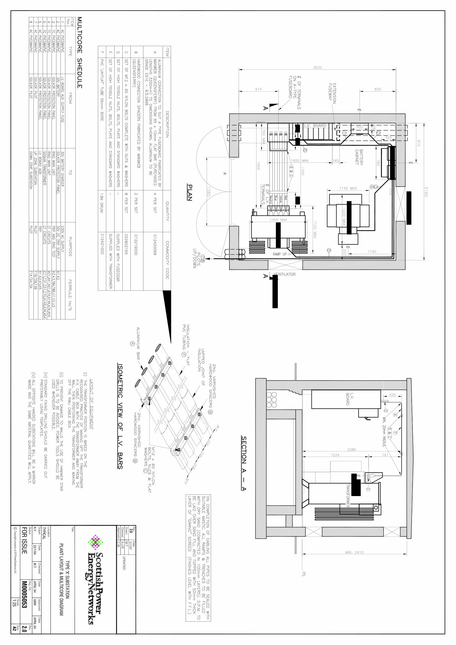
Equipment layout and multicore cables shall be in accordance with EnergyNewtorks drawing, M0005053.
SECONDARY SUBSTATION INSTALLATION AND
COMMISSIONING SPECIFICATION
SUB-02-006 Issue No. 5
___________________________________________________________________________ © SP Power Systems Limited Page 15 of 32
11. INDUSTRIAL HV CUSTOMER RMU SUBSTATIONS
This section covers the ‘Industrial HV ’ type substations used predominantly in SP Manweb plc. The general layout of the site will be as per Figure 3. An ‘Industrial HV’ type substation comprises of the following Equipment: • 11kV Ring Main Unit • 11kV Metering Unit • 11kV Tariff Metering Equipment • Customer Emergency 11kV Disconnection Equipment
11.1 Enclosure
An Approved prefabricated GRP enclosure shall be the preferred means of installation in compliance with section 8.2. The dimensions and construction of the GRP enclosed HV Customer RMU substation shall be as shown on EnergyNetworks drawing SP2142493 as detailed in SUB-03-017. Industrial HV Customer RMU substations which are proposed to be constructed with a Masonry/brick enclosure or any other non Approved enclosure at EnergyNetworks expense and fall outwith the guidelines detailed in section 8.2, shall only be installed after formal written approval has been given by the Engineering Services Manager or his nominated representative. The customers’ incoming switchgear must be situated so as to provide easy access and the HV cable should be as short as possible between the point of supply and the customers’ switchgear. The HV cable shall not be exposed by more than 1m inside the customers’ premises as it still falls under the EnergyNetworks zone of protection. The cable itself shall be adequately protected with respect to mechanical damage. An Emergency Trip facility will be provided to the customer for HV disconnection of the incoming supply. The tripping facility shall be mounted adjacent to the customers metering equipment and be easily identifiable. In addition a flag relay shall be mounted adjacent to the EnergyNetworks RMU to give local indication of a customer emergency tripping action being carried out.

SECONDARY SUBSTATION INSTALLATION AND
COMMISSIONING SPECIFICATION
SUB-02-006 Issue No. 5
___________________________________________________________________________ © SP Power Systems Limited Page 16 of 32
11.2 Metering
The metering unit shall be of an approved type as detailed in the EnergyNetworks Approved Equipment Register.
SECONDARY SUBSTATION INSTALLATION AND
COMMISSIONING SPECIFICATION
SUB-02-006 Issue No. 5
___________________________________________________________________________ © SP Power Systems Limited Page 17 of 32
12. INDUSTRIAL LV CUSTOMER SUBSTATIONS
This section covers the ‘Industrial LV’ type substation. The general layout of the site will be as per Figure 4. An Industrial LV Customer substation comprises of the following equipment: • 11kV/433V Transformer • Transformer mounted 11kV Ring Main Unit • Transformer mounted 400V fuse cabinet with metered ways. • 400V Tariff Metering Equipment The general layout of the site is similar to the unit substation except it has a customer metering annex as shown in Figure 4. It should be noted however, that depending on the distance between the LV point of supply and industrial premises, the customer tariff metering equipment may be situated in the metering annex to the secondary substation or could be situated in the customers premises.
12.1 Enclosure
An Approved prefabricated GRP enclosure shall be the preferred means of installation in compliance with section 8.2. The dimensions and construction of the GRP enclosed Industrial LV Customer substation shall be as shown on EnergyNetworks drawing SP2103445 as detailed in SUB-03-017. Industrial LV Customer substations which are proposed to be constructed with a Masonry/brick enclosure or any other non Approved enclosure at EnergyNetworks expense and fall outwith the guidelines detailed in section 8.2, shall only be installed after formal written approval has been given by the Engineering Services Manager or his nominated representative.
12.2 Metering
The metering current transformers are located in the LV distribution board.

SECONDARY SUBSTATION INSTALLATION AND
COMMISSIONING SPECIFICATION
SUB-02-006 Issue No. 5
___________________________________________________________________________ © SP Power Systems Limited Page 18 of 32
13. HV CUSTOMER SWITCHBOARD SUBSTATION
This section covers the ‘HV customer switchboard’ type substation. The general layout of the site will be as per Figure 5, which also includes a typical equipment layout. An HV Customer Switchboard substation comprises of the following equipment: • 3 Panel 11kV Extensible Switchboard with Appropriate Protection (SOLKOR) • 11kV Tariff Metering Equipment • Customer Emergency 11kV Disconnection Equipment • Battery and Charger
13.1 Enclosure
This particular type of substation contains Indoor Equipment which requires to be installed in a suitable permanent brick built enclosure. The enclosure shall be of a masonry/brick construction in accordance with EnergyNetworks drawing SP4008870 A pitched roof can be used where the condition of site or planning acquisition requires it. The minimum internal height at all points within the enclosure shall meet the requirements of EnergyNetworks Drawing SP4008870
13.2 Substation LV Services
Building services, lighting and LV power shall be installed in accordance with section 8.7.
13.3 Emergency HV Disconnection
An Emergency Trip facility will be provided to the customer for 11kV disconnection of the incoming supply. The tripping facility shall be mounted adjacent to the customers metering equipment and be easily identifiable. In addition a flag relay shall be mounted on the EnergyNetworks customer feeder circuit breaker protection panel to give local indication of a customer emergency tripping action being carried out.
SECONDARY SUBSTATION INSTALLATION AND
COMMISSIONING SPECIFICATION
SUB-02-006 Issue No. 5
___________________________________________________________________________ © SP Power Systems Limited Page 19 of 32
14. COMMISSIONING
Prior to Energisation, all Equipment shall be Visually inspected and Mechanically & Electrically tested in accordance with sections 14.1–14.5. Where it is deemed by the nominated EnergyNetworks commissioning Engineer that the equipment does not comply with the requirements outlined in sections 14.1–14.5, then where this cannot be resolved on site, the Equipment shall not be energised and a defect report, as detailed in QUAL-04-001 (DOM 3.2.4) shall be submitted to the Engineering Services group, Bellshill, detailing the appropriate defect. Where the Equipment is being installed by an ICP, the Equipment shall not be adopted. Previously In Service Equipment which is deemed suitable for re-use in accordance with EnergyNetworks document ASSET-01-010 shall be refurbished and electrically tested in accordance with the requirements detailed in SUB-02-613 prior to site, as appropriate. The substation commissioning results shall be formally recorded via Appendix 4 and signed where appropriate. A paper copy of the ‘Substation Commissioning Progress Card shall be sent to: EnergyNetworks Data Management Bureau St Vincent Crescent Glasgow G3 8LT Internal Telephone: 733 4198 External Telephone: 0141 567 4198 Internal Fax: 733 4262 External Fax: 0141 567 4262 Email: [email protected]
14.1 Visual Inspection
A visual inspection shall be undertaken once the equipment has been delivered to site in accordance with Appendix 3 – Equipment Check List and Appendix 4 – Substation Commissioning Progress Card – ‘Visual Inspection’.
14.2 Mechanical Testing
On site mechanical tests shall be undertaken at site in accordance with Appendix 4 – Substation Commissioning Progress Card – ‘Mechanical Testing’.
SECONDARY SUBSTATION INSTALLATION AND
COMMISSIONING SPECIFICATION
SUB-02-006 Issue No. 5
___________________________________________________________________________ © SP Power Systems Limited Page 20 of 32
14.3 Protection Testing
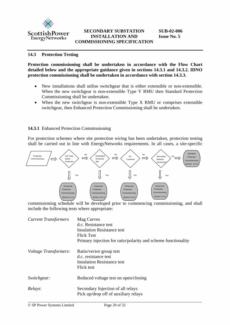
Protection commissioning shall be undertaken in accordance with the Flow Chart detailed below and the appropriate guidance given in sections 14.3.1 and 14.3.2. IDNO protection commissioning shall be undertaken in accordance with section 14.3.3.
• New installations shall utilise switchgear that is either extensible or non-extensible. When the new switchgear is non-extensible Type Y RMU then Standard Protection Commissioning shall be undertaken.
• When the new switchgear is non-extensible Type X RMU or comprises extensible switchgear, then Enhanced Protection Commissioning shall be undertaken.
14.3.1 Enhanced Protection Commissioning
For protection schemes where site protection wiring has been undertaken, protection testing shall be carried out in line with EnergyNetworks requirements. In all cases, a site-specific
commissioning schedule will be developed prior to commencing commissioning, and shall include the following tests where appropriate: Current Transformers Mag Curves d.c. Resistance test Insulation Resistance test Flick Test Primary injection for ratio/polarity and scheme functionality Voltage Transformers: Ratio/vector group test d.c. resistance test Insulation Resistance test Flick test Switchgear: Reduced voltage test on open/closing Relays: Secondary Injection of all relays Pick up/drop off of auxiliary relays
Protection Commissioning Unit Type
Protection Standard
Protection
Commissioning
Section 14.3.2
EmbeddedGenerator
HV
Yes
No
Enhanced Protection
Commissioning Section 14.3.1
Secondary Connection Network NoNoNo
Yes Yes Yes
CustomerSite
Solkor
Enhanced Protection
Commissioning Section 14.3.1
Enhanced
Protection
Commissioning
Section 14.3.1
Enhanced
Protection
Commissioning
Section 14.3.1
SECONDARY SUBSTATION INSTALLATION AND
COMMISSIONING SPECIFICATION
SUB-02-006 Issue No. 5
___________________________________________________________________________ © SP Power Systems Limited Page 21 of 32
Protection Scheme: Insulation resistance of secondary wiring Full functional test of scheme according to the appropriate
schematic Batteries: Functional Test Post energising tests: Trip test Load checks on protections Where the enhanced Protection commissioning is being undertaken by an ICP, then it is EnergyNetworks policy to witness the tests prior to adoption. Tests to be witnessed, to be agreed locally prior to commissioning starting.
14.3.2 Standard Protection Commissioning
The standard protection commissioning tests shall be employed on non-extensible RMUs which utilise either time lag fuses (TLFs) or a self-powered relay to protect the outgoing cable (and transformer, where appropriate).
• Where TLFs are used, each fuse/link shall be removed and the ac trip coil injected using the Nortech Test Set. This test will confirm tripping of the HV CB. This test should be carried out on both phases and earth.
Where a self-powered relay is employed, then the relay should be tested using a bespoke test device to ensure tripping of the CB. Where no bespoke test device is available, then the relay shall be secondary injected to ensure operation.
14.3.3 IDNO Protection Commissioning
Where the Company network interfaces with an IDNO network then the appropriate Protection commissioning as detailed in SUB-02-013 shall be undertaken.
14.4 Electrical Insulation Testing
All HV Equipment shall be electrically tested where appropriate, at site in accordance with EnergyNetworks document SUB-02-613.
14.5 Pre-Energisation Checks
Appendix 4 details the Pre Energisation checks to be undertaken.
SECONDARY SUBSTATION INSTALLATION AND
COMMISSIONING SPECIFICATION
SUB-02-006 Issue No. 5
___________________________________________________________________________ © SP Power Systems Limited Page 22 of 32
APPENDIX 1– DIAGRAMS
• Typical site Layout for a Unit Substation • Typical Layout for a ‘X’ Type Substation • Typical Layout for an Industrial HV Customer Substation • Typical Layout for an Industrial LV Customer Substation • Typical Layout for an Industrial HV Switching Substation

SECONDARY SUBSTATION INSTALLATION AND
COMMISSIONING SPECIFICATION
SUB-02-006 Issue No. 5
___________________________________________________________________________ © SP Power Systems Limited Page 23 of 32
Figure 1 – Typical site Layout for a Unit Substation
SECONDARY SUBSTATION INSTALLATION AND
COMMISSIONING SPECIFICATION
SUB-02-006 Issue No. 5
___________________________________________________________________________ © SP Power Systems Limited Page 24 of 32
Figure 2 – Typical Layout for a ‘X’ Type Substation

SECONDARY SUBSTATION INSTALLATION AND
COMMISSIONING SPECIFICATION
SUB-02-006 Issue No. 5
___________________________________________________________________________ © SP Power Systems Limited Page 25 of 32
Figure 3 – Typical Layout for an Industrial HV Customer Substation

SECONDARY SUBSTATION INSTALLATION AND
COMMISSIONING SPECIFICATION
SUB-02-006 Issue No. 5
___________________________________________________________________________ © SP Power Systems Limited Page 26 of 32
Figure 4 – Typical Layout for an Industrial LV Customer Substation

SECONDARY SUBSTATION INSTALLATION AND
COMMISSIONING SPECIFICATION
SUB-02-006 Issue No. 5
___________________________________________________________________________ © SP Power Systems Limited Page 27 of 32
Figure 5 – Typical Layout for an Industrial HV Switching Substation

SECONDARY SUBSTATION INSTALLATION AND
COMMISSIONING SPECIFICATION
SUB-02-006 Issue No. 5
___________________________________________________________________________ © SP Power Systems Limited Page 28 of 32
APPENDIX 2 – DRAWING REGISTER
X – Type Non Unit Substation Drawing Number Revision M0005053 2 LV Services Drawing Number Revision M0001181 C
SECONDARY SUBSTATION INSTALLATION AND
COMMISSIONING SPECIFICATION
SUB-02-006 Issue No. 5
___________________________________________________________________________ © SP Power Systems Limited Page 29 of 32
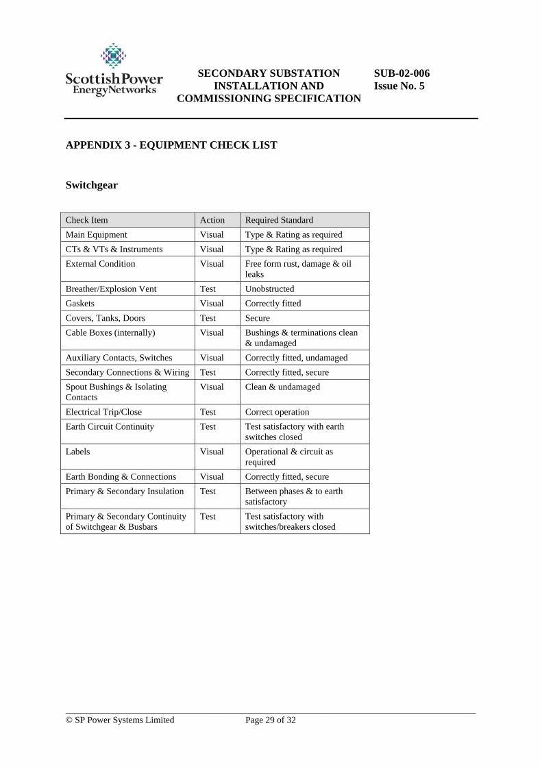
APPENDIX 3 - EQUIPMENT CHECK LIST
Switchgear
Check Item Action Required Standard Main Equipment Visual Type & Rating as required CTs & VTs & Instruments Visual Type & Rating as required External Condition Visual Free form rust, damage & oil
leaks Breather/Explosion Vent Test Unobstructed Gaskets Visual Correctly fitted Covers, Tanks, Doors Test Secure Cable Boxes (internally) Visual Bushings & terminations clean
& undamaged Auxiliary Contacts, Switches Visual Correctly fitted, undamaged Secondary Connections & Wiring Test Correctly fitted, secure Spout Bushings & Isolating Contacts
Visual Clean & undamaged
Electrical Trip/Close Test Correct operation Earth Circuit Continuity Test Test satisfactory with earth
switches closed Labels Visual Operational & circuit as
required Earth Bonding & Connections Visual Correctly fitted, secure Primary & Secondary Insulation Test Between phases & to earth
satisfactory Primary & Secondary Continuity of Switchgear & Busbars
Test Test satisfactory with switches/breakers closed

SECONDARY SUBSTATION INSTALLATION AND
COMMISSIONING SPECIFICATION
SUB-02-006 Issue No. 5
___________________________________________________________________________ © SP Power Systems Limited Page 30 of 32
Transformers (1000kVA and below)
Check Item Action Required Standard Main Equipment Visual Type & Rating as required External Condition Visual Free form rust, damage & oil
leaks Insulating Oil – Level Visual Filled to correct level Gaskets Visual Correctly fitted Breather Visual Transport plug removed,
unobstructed Drain Plug Valve Visual Tight, free from leaks Tap Change Switch Test Correct operation, locked Internal Tapping Links Visual Correct position, secure Cable Boxes (internally) Visual Bushings & terminations clean
& undamaged Bushings & Insulation in Air Visual Clean, undamaged, secure Spark Gaps Measure Correct for voltage Earth Bonding & Connection Visual Correctly fitted, secure
LV Equipment
Check Item Action Required Standard Main Equipment Visual Type & Rating as required External Condition Visual Free form rust, damage & oil
leaks Interior Visual Assembled correctly,
undamaged Contact Alignment Operate Correct in all fuse & link
positions Operating Handles Operate Correct operation, undamaged Transformer Isolating Links Operate Correct operation, lockable Inter-phase & Earth Screen Barriers
Visual Secure & correctly fitted
Locking Facilities Visual Correct MDI Metering Visual Correctly fitted Auxiliary Supply Connection Visual Secure Labels Visual Circuit, Resuscitation, PME
fitted as required
SECONDARY SUBSTATION INSTALLATION AND
COMMISSIONING SPECIFICATION
SUB-02-006 Issue No. 5
___________________________________________________________________________ © SP Power Systems Limited Page 31 of 32
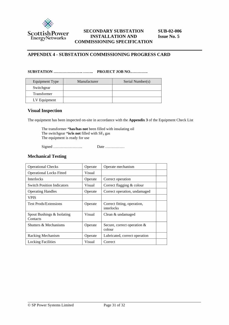
APPENDIX 4 - SUBSTATION COMMISSIONING PROGRESS CARD
SUBSTATION ………………….. …….. PROJECT JOB NO.………….
Equipment Type Manufacturer Serial Number(s) Switchgear Transformer LV Equipment
Visual Inspection
The equipment has been inspected on-site in accordance with the Appendix 3 of the Equipment Check List The transformer *has/has not been filled with insulating oil
The switchgear *is/is not filled with SF6 gas The equipment is ready for use
Signed ………………….. Date ……………
Mechanical Testing
Operational Checks Operate Operate mechanism Operational Locks Fitted Visual Interlocks Operate Correct operation Switch Position Indicators Visual Correct flagging & colour Operating Handles Operate Correct operation, undamaged VPIS Test Prods/Extensions Operate Correct fitting, operation,
interlocks
Spout Bushings & Isolating Contacts
Visual Clean & undamaged
Shutters & Mechanisms Operate Secure, correct operation & colour
Racking Mechanism Operate Lubricated, correct operation Locking Facilities Visual Correct
SECONDARY SUBSTATION INSTALLATION AND
COMMISSIONING SPECIFICATION
SUB-02-006 Issue No. 5
___________________________________________________________________________ © SP Power Systems Limited Page 32 of 32
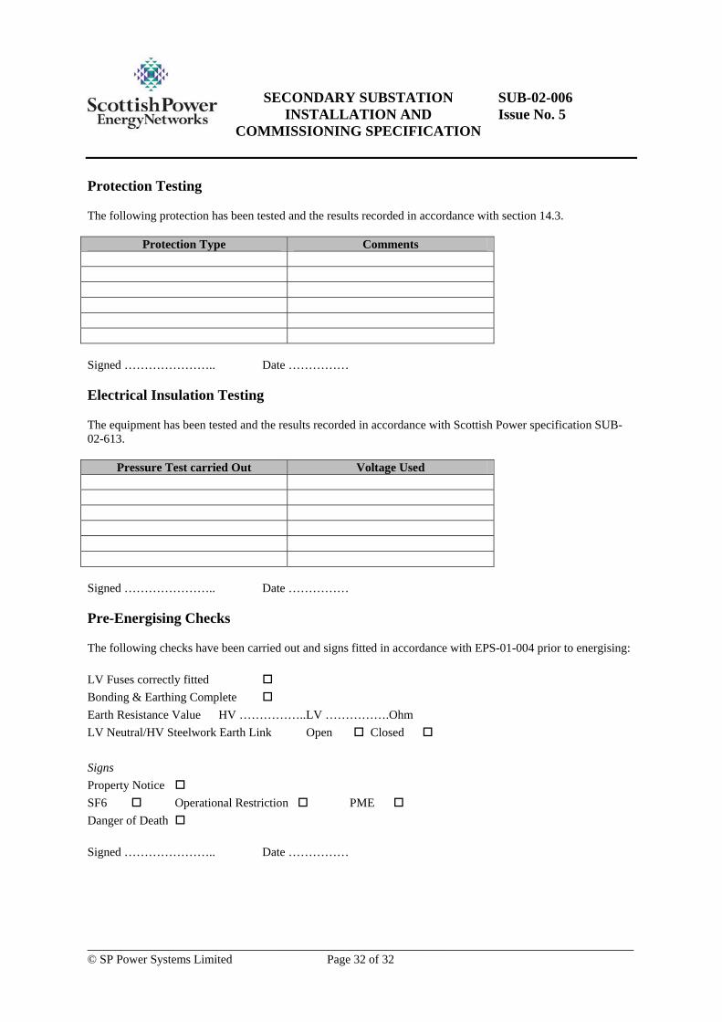
Protection Testing
The following protection has been tested and the results recorded in accordance with section 14.3.
Protection Type Comments
Signed ………………….. Date ……………
Electrical Insulation Testing
The equipment has been tested and the results recorded in accordance with Scottish Power specification SUB-02-613.
Pressure Test carried Out Voltage Used
Signed ………………….. Date ……………
Pre-Energising Checks
The following checks have been carried out and signs fitted in accordance with EPS-01-004 prior to energising: LV Fuses correctly fitted Bonding & Earthing Complete Earth Resistance Value HV …………….. LV …………….Ohm LV Neutral/HV Steelwork Earth Link Open Closed Signs Property Notice SF6 Operational Restriction PME Danger of Death Signed ………………….. Date ……………
Related Documents


