Comfort Heating Sizing Guide Training The facts and the recommendations made in this publication are based on our own research and the research of others and are believed to be accurate. We cannot anticipate all conditions under which this information and our products or the products of other manufacturers in combination with our products may be used. We accept no responsibility for results obtained by the application of this information or the safety and suitability of our products either alone or in combination with other products. Users are advised to make their own tests to determine the safety and suitability of each such product or product combination for their own purposes. Written By Paul Rannick Adam Heiligenstein Chromalox ® , Inc. 103 Gamma Drive Pittsburgh, PA 15238 (412) 967-3800 Trademarks: NFPA and NEC are registered trademarks of National Fire Protection Association UL is a trademark of Underwriter Laboratories, Inc. FM is a trademark of Factory Mutual Research Corporation CSA is a registered trademark of Canadian Standards Association Revised 5/06

Welcome message from author
This document is posted to help you gain knowledge. Please leave a comment to let me know what you think about it! Share it to your friends and learn new things together.
Transcript
PF501-2
Comfort HeatingSizing guide
© 2014 Chromalox, Inc.

Corporate Headquarters Chromalox, inc. 103 Gamma Drive Pittsburgh, PA 15238Phone: (412) 967-3800 Fax: (412) 967-5148
PF501-2February 2014
1© 2014 Chomalox, Inc.
Comfort Heating Sizing GuideTraining
The facts and the recommendations made in thispublication are based on our own research and theresearch of others and are believed to be accurate.
We cannot anticipate all conditions under which thisinformation and our products or the products ofother manufacturers in combination with ourproducts may be used. We accept no responsibilityfor results obtained by the application of thisinformation or the safety and suitability of ourproducts either alone or in combination with otherproducts. Users are advised to make their owntests to determine the safety and suitability of eachsuch product or product combination for their ownpurposes.
Written ByPaul Rannick
Adam Heiligenstein
Chromalox®, Inc.103 Gamma Drive
Pittsburgh, PA 15238(412) 967-3800
Trademarks:NFPA and NEC are registered trademarks of National Fire Protection AssociationUL is a trademark of Underwriter Laboratories, Inc.FM is a trademark of Factory Mutual Research CorporationCSA is a registered trademark of Canadian Standards Association
Revised 5/06
2 © 2014 Chomalox, Inc.
Comfort Heating Sizing GuideTraining

3© 2014 Chomalox, Inc.
Comfort Heating Sizing GuideTraining
Methods of Heat TransferTo thoroughly understand which method of comfort heating best meets yourapplication, it is important to understand the basic methods of heat transfer. Heattransfer is accomplished by CONDUCTION, CONVECTION, or RADIATION.
CONDUCTION is defined as transferring heat through a conducting medium by way ofdirect contact.
CONVECTION transfers heat via a medium such as liquid or air. In comfort heating asource of heat is used to warm the air and create a desired comfort level aroundpeople. Heated air can be circulated by fans or blowers to disperse the heat in a largeenclosed area. Home heating with a forced-air furnace is an example ofCONVECTION heat.
RADIANT, or INFRARED heat uses invisible, electromagnetic waves from an energysource. An example of electromagnetic infrared energy is heat from the sun. In aninfrared system, these energy waves are created by a heat source - quartz lamp, quartztube, or tubular. These waves are directed by optically designed reflectors toward oronto the object or person being heated. A fireplace is a familiar form of radiant heat.
Sizing Comfort Heating ApplicationsTo get an approximate sizing of the heating requirements for a room, the followingguide may be utilized. For a more detailed analysis it is recommended that theASHRAE guidelines be followed when performing an analysis for a completebuilding. Also available is a computer-sizing tool that is designed to perform room-by-room heat loss estimates. When sizing the job, the first step is to determine theconstruction data and sizing requirements. You will need to collect the followinginformation: • Voltage and phase • Length, width, and height of building • R-factor for ceilings and walls • Air changes or how much fresh air is brought in per hour • Outside lowest temperature • Desired inside temperature • Size and number of windows and doors • Floor Construction
4 © 2014 Chomalox, Inc.
Comfort Heating Sizing GuideTraining
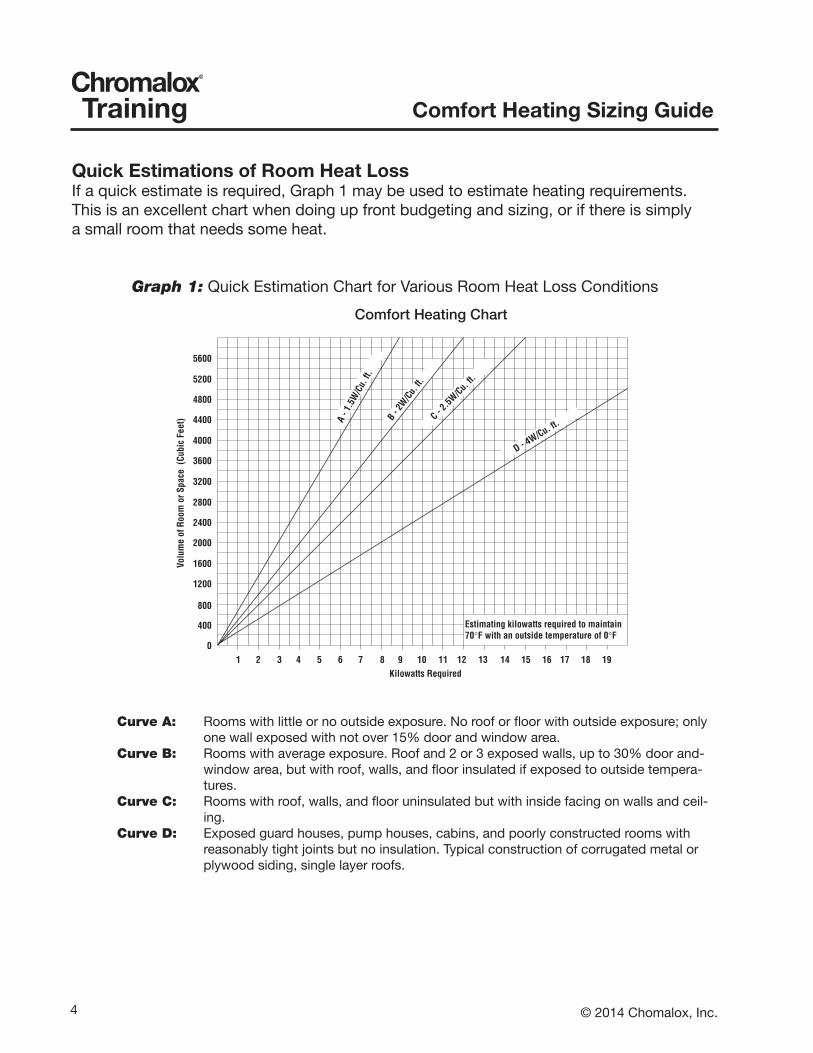
Quick Estimations of Room Heat LossIf a quick estimate is required, Graph 1 may be used to estimate heating requirements.This is an excellent chart when doing up front budgeting and sizing, or if there is simplya small room that needs some heat.
Graph 1: Quick Estimation Chart for Various Room Heat Loss Conditions
Curve A: Rooms with little or no outside exposure. No roof or floor with outside exposure; only one wall exposed with not over 15% door and window area.
Curve B: Rooms with average exposure. Roof and 2 or 3 exposed walls, up to 30% door and-window area, but with roof, walls, and floor insulated if exposed to outside tempera-tures.
Curve C: Rooms with roof, walls, and floor uninsulated but with inside facing on walls and ceil-ing.
Curve D: Exposed guard houses, pump houses, cabins, and poorly constructed rooms with reasonably tight joints but no insulation. Typical construction of corrugated metal or plywood siding, single layer roofs.
A- 1
5.W
C/u.
.tf
-B
2W/
uC.
tf .C - 2 5. W/Cu.
ft.
D
.uC/W4-
.tf
5600
5200
4800
4400
4000
3600
3200
2800
2400
2000
1600
1200
800
400
0
)teeF cibuC( ecapS ro moo
R fo emuloV
1 2 3 4 5 6 7 8 9 10 11 12 13 14 15 16 17 18 19Kilowatts Required
Comfort Heating Chart
Estimating kilowatts required to maintain70°F with an outside temperature of 0°F

5© 2014 Chomalox, Inc.
Comfort Heating Sizing GuideTraining
General Industrial Sizing GuideIf more detail is required when doing the application sizing, a worksheet can be foundat the back of this manual that may be used when gathering information and performingthe calculations. A sample of the worksheet is shown below. The factors for the Uvaluesmay be found in Table 1 on the next page. NOTE: U = 1 / R. In addition,outside design temperatures may be found in Table 2 for various parts of the country.
Figure 1: Heat Loss Calculation Form for General IndustrialApplications
CHROMALOXGeneral Industrial Sizing Guide
Heat Loss Calculation- Indoor
Job Name: Date:Location: Room:
Bid Number: Reference:
Voltage: V Phase:
Room SizeLength: ft. Width: ft. Ceiling Height: ft.
Total Square Footage: square feet
Heater Mounting Height: ft.
Design InformationCeiling R-Factor: Outside Design Temperature: F
Wall R-Factor: Desired Inside Temperature: FTemperature Rise: F
Air Changes Per Hour: cubic foot per hour
CalculationItem Area sq-ft X U-Factor = BTU/Hr/Degree FWindows sq-ft X =
Doors sq-ft X =Net Wall sq-ft X =
Roof sq-ft X =Floor Perimeter * ft X =
Item A TOTAL = BTU/Hr/degree F* For floor perimeter use U-factor of 1.2, 0.7, or 0.6 for exposed, 1" insulation, or 2" insulation respectively
Air Change Loss Cubic foot per hour X 0.019 BTU/cubic ft. = BTU/hr/degree FItem B cubic ft./hr X 0.019 BTU/cubic ft. =
TOTAL Item A + Item B = BTU/Hr/degree F
Item C Convert to Watts = Total / 3.412 = Watts/Hr/degree F
TOTAL HEATING REQUIREMENTItem C x Temperature Rise = Watts/Hr
Watts/Hr/degree F X degree F =Total Watts/Hr.
6 © 2014 Chomalox, Inc.
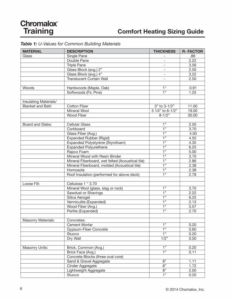
Comfort Heating Sizing GuideTrainingTable 1: U-Values for Common Building MaterialsMATERIAL DESCRIPTION THICKNESS R- FACTORGlass Single Pane - .88 Double Pane - 2.22 Triple Pane - 3.56 Glass Block (avg.) 2” - 2.50 Glass Block (avg.) 4” - 3.22 Translucent Curtain Wall - 2.50
Woods Hardwoods (Maple, Oak) 1” 0.91 Softwoods (Fir, Pine) 1” 1.25
Insulating Materials/Blanket and Batt: Cotton Fiber 3” to 3-1/2” 11.00 Mineral Wool 5 1⁄4” to 6-1/2” 19.00 Wood Fiber 8-1/2” 30.00
Board and Slabs: Cellular Glass 1” 2.50 Corkboard 1” 3.70 Glass Fiber (Avg.) 1” 4.00 Expanded Rubber (Rigid) 1” 4.55 Expanded Polystyrene (Styrofoam) 1” 4.35 Expanded Polyurethene 1” 6.25 Rapco Foam 1” 5.00 Mineral Wood with Resin Binder 1” 3.70 Mineral Fiberboard, wet felted (Acoustical tile) 1” 2.86 Mineral Fiberboard, molded (Acoustical tile) 1” 2.38 Homosote 1” 2.38 Roof Insulation (performed for above deck) 1” 2.78
Loose Fill: Cellulose 1 “ 3.70 Mineral Wool (glass, slag or rock) 1” 3.70 Sawdust or Shavings 1” 2.22 Silica Aerogel 1” 6.25 Vermiculite (Expanded) 1” 2.13 Wood Fiber (Avg.) 1” 3.57 Perlite (Expanded) 1” 2.70
Masonry Materials: Concretes: Cement Mortar 1” 0.20 Gypsum-Fiber Concrete 1” 0.60 Stucco 1” 0.20 Dry Wall 1/2” 0.50
Masonry Units: Brick, Common (Avg.) 1” 0.20 Brick Face (Avg.) 1” 0.11 Concrete Blocks (three oval core) Sand & Gravel Aggregate 8” 1.11 Cinder Aggregate 8” 1.72 Lightweight Aggregate 8” 2.00 Stucco 1” 0.20
7© 2014 Chomalox, Inc.
Comfort Heating Sizing GuideTraining
Table 1: U-Values for Common Building Materials (cont’d)MATERIAL DESCRIPTION THICKNESS R- FACTORSiding Materials: Wood (7-1⁄2” Exposure) 16” 0.87 Wood (12” Exposure) 10” 1.19 Asphalt roll siding - 0.15 Asphalt insulating siding 112’ bd. - 1.46 Wood, plywood, %’ lapped - 0.59 Wood, bevel, 1⁄2’ x 8” lapped - 0.81 Sheet Metal, single sheet (avg.) - 0.83 Architectural Glass - 0.10
Roofing: Asphalt Shingles - 0.44 Slate 1⁄2 “ 0.05 Built-up Roofing 3/8 “ 0.33
Air Spaces: Horizontal: Ordinary materials-vertical flow 3⁄4” to 4” 0.80 Vertical: Ordinary matericals-horizontal flow 3⁄4” to 4” .96
Exposed Doors: Metal-Single Sheet - 0.83 Wood 1” 1.56 Wood 2” 2.33
NOTE: RFactor = L/k, where L is the thickness in inches and k is BTU*in / (ft2*°F*hr)
Table 2: Typical Outside Design Temperatures for the United States Yearly Outside Mean Wind Heating Snowfall DesignState City Speed: MPH3 Degree Days1 Mean4 TempAlabama Birmingham 7.4 2844.0 1.2 17.0 Huntsville 8.0 3302.0 2.5 11.0 Mobile 9.2 1684.0 0.5 25.0 Montgomery 6.8 2269.0 0.4 22.0Alaska Anchorage 6.7 10911.0 70.2 -23.0 Fairbanks 5.3 14344.0 68.8 -51.0 Juneau 8.5 9007.0 108.2 -4.0 Nome 10.8 14325.0 54.5 -31.0Arizona Flagstaff 7.4 7322.0 88.6 -2.0 Pheonix 6.2 1552.0 0.0 31.0 Tucson 8.2 1752.0 1.4 28.0 Winslow 8.8 4733.0 11.1 5.0
8 © 2014 Chomalox, Inc.
Comfort Heating Sizing GuideTraining
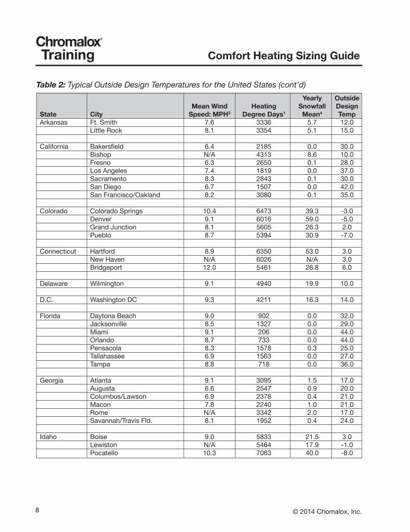
Table 2: Typical Outside Design Temperatures for the United States (cont’d) Yearly Outside Mean Wind Heating Snowfall DesignState City Speed: MPH3 Degree Days1 Mean4 TempArkansas Ft. Smith 7.6 3336 5.7 12.0 Little Rock 8.1 3354 5.1 15.0
California Bakersfield 6.4 2185 0.0 30.0 Bishop N/A 4313 8.6 10.0 Fresno 6.3 2650 0.1 28.0 Los Angeles 7.4 1819 0.0 37.0 Sacramento 8.3 2843 0.1 30.0 San Diego 6.7 1507 0.0 42.0 San Francisco/Oakland 8.2 3080 0.1 35.0
Colorado Colorado Springs 10.4 6473 39.3 -3.0 Denver 9.1 6016 59.0 -5.0 Grand Junction 8.1 5605 26.3 2.0 Pueblo 8.7 5394 30.9 -7.0
Connecticut Hartford 8.9 6350 53.0 3.0 New Haven N/A 6026 N/A 3.0 Bridgeport 12.0 5461 26.8 6.0
Delaware Wilmington 9.1 4940 19.9 10.0
D.C. Washington DC 9.3 4211 16.3 14.0
Florida Daytona Beach 9.0 902 0.0 32.0 Jacksonville 8.5 1327 0.0 29.0 Miami 9.1 206 0.0 44.0 Orlando 8.7 733 0.0 44.0 Pensacola 8.3 1578 0.3 25.0 Tallahassee 6.9 1563 0.0 27.0 Tampa 8.8 718 0.0 36.0
Georgia Atlanta 9.1 3095 1.5 17.0 Augusta 6.6 2547 0.9 20.0 Columbus/Lawson 6.9 2378 0.4 21.0 Macon 7.8 2240 1.0 21.0 Rome N/A 3342 2.0 17.0 Savannah/Travis Fld. 8.1 1952 0.4 24.0
Idaho Boise 9.0 5833 21.5 3.0 Lewiston N/A 5464 17.9 -1.0 Pocatello 10.3 7063 40.0 -8.0
9© 2014 Chomalox, Inc.
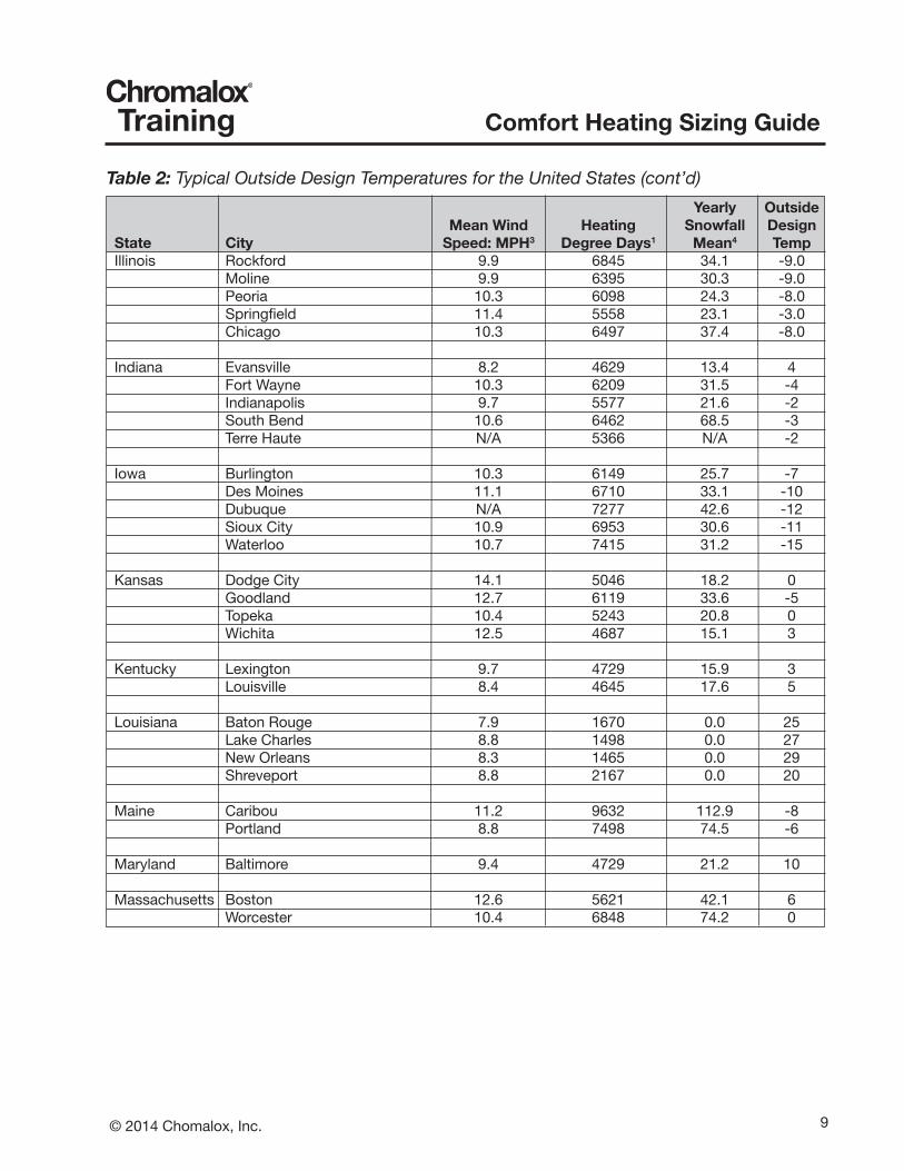
Comfort Heating Sizing GuideTrainingTable 2: Typical Outside Design Temperatures for the United States (cont’d) Yearly Outside Mean Wind Heating Snowfall DesignState City Speed: MPH3 Degree Days1 Mean4 TempIllinois Rockford 9.9 6845 34.1 -9.0 Moline 9.9 6395 30.3 -9.0 Peoria 10.3 6098 24.3 -8.0 Springfield 11.4 5558 23.1 -3.0 Chicago 10.3 6497 37.4 -8.0
Indiana Evansville 8.2 4629 13.4 4 Fort Wayne 10.3 6209 31.5 -4 Indianapolis 9.7 5577 21.6 -2 South Bend 10.6 6462 68.5 -3 Terre Haute N/A 5366 N/A -2
Iowa Burlington 10.3 6149 25.7 -7 Des Moines 11.1 6710 33.1 -10 Dubuque N/A 7277 42.6 -12 Sioux City 10.9 6953 30.6 -11 Waterloo 10.7 7415 31.2 -15
Kansas Dodge City 14.1 5046 18.2 0 Goodland 12.7 6119 33.6 -5 Topeka 10.4 5243 20.8 0 Wichita 12.5 4687 15.1 3
Kentucky Lexington 9.7 4729 15.9 3 Louisville 8.4 4645 17.6 5
Louisiana Baton Rouge 7.9 1670 0.0 25 Lake Charles 8.8 1498 0.0 27 New Orleans 8.3 1465 0.0 29 Shreveport 8.8 2167 0.0 20
Maine Caribou 11.2 9632 112.9 -8 Portland 8.8 7498 74.5 -6
Maryland Baltimore 9.4 4729 21.2 10
Massachusetts Boston 12.6 5621 42.1 6 Worcester 10.4 6848 74.2 0

10 © 2014 Chomalox, Inc.
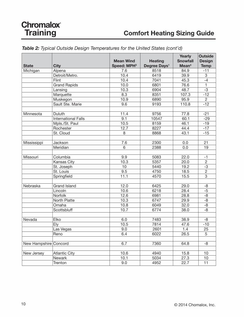
Comfort Heating Sizing GuideTrainingTable 2: Typical Outside Design Temperatures for the United States (cont’d) Yearly Outside Mean Wind Heating Snowfall DesignState City Speed: MPH3 Degree Days1 Mean4 TempMichigan Alpena 7.6 8518 84.9 -11 Detroit/Metro. 10.4 6419 39.9 3 Flint 10.4 7041 45.3 -4 Grand Rapids 10.0 6801 76.6 1 Lansing 10.3 6904 48.7 -3 Marquette 8.3 8351 107.3 -12 Muskegon 10.9 6890 95.9 2 Sault Ste. Marie 9.6 9193 110.8 -12
Minnesota Duluth 11.4 9756 77.8 -21 International Falls 9.1 10547 60.1 -29 Mpls./St. Paul 10.5 8159 46.1 -19 Rochester 12.7 8227 44.4 -17 St. Cloud 8 8868 43.1 -15
Mississippi Jackson 7.6 2300 0.0 21 Meridian 6 2388 0.0 19
Missouri Columbia 9.9 5083 22.0 -1 Kansas City 10.3 5357 20.0 2 St. Joseph 10 5440 19.2 -3 St. Louis 9.5 4750 18.5 2 Springfield 11.1 4570 15.5 3
Nebraska Grand Island 12.0 6425 29.0 -8 Lincoln 10.6 6218 28.4 -5 Norfolk 12.6 6981 28.8 -8 North Platte 10.3 6747 29.9 -8 Omaha 10.8 6049 32.0 -8 Scottsbluff 10.7 6774 38.0 -8
Nevada Elko 6.0 7483 38.9 -8 Ely 10.5 7814 47.6 -10 Las Vegas 9.0 2601 1.4 25 Reno 6.4 6022 26.5 5
New Hampshire Concord 6.7 7360 64.8 -8
New Jersey Atlantic City 10.6 4940 15.8 10 Newark 10.1 5034 27.3 10 Trenton 9.0 4952 22.7 11
11© 2014 Chomalox, Inc.
Comfort Heating Sizing GuideTraining
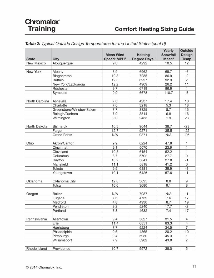
Table 2: Typical Outside Design Temperatures for the United States (cont’d) Yearly Outside Mean Wind Heating Snowfall DesignState City Speed: MPH3 Degree Days1 Mean4 TempNew Mexico Albuquerque 9.0 4292 10.5 12
New York Albany 8.9 6962 65.7 -6 Binghamton 10.3 7285 86.9 -2 Buffalo 12.3 6927 92.9 2 New York/LaGuardia 12.2 4909 26.2 11 Rochester 9.7 6719 86.9 1 Syracuse 9.9 6678 110.7 -3
North Carolina Asheville 7.8 4237 17.4 10 Charlotte 7.6 3218 5.3 18 Greensboro/Winston-Salem 7.7 3825 8.7 15 Raleigh/Durham 7.9 3514 6.8 16 Wilmington 9.0 2433 1.9 23
North Dakota Bismarck 10.5 9044 38.7 -23 Fargo 12.7 9271 35.5 -22 Grand Forks N/A 9871 N/A -26
Ohio Akron/Canton 9.9 6224 47.8 1 Cincinnati 9.1 5070 23.9 1 Cleveland 10.8 6154 52.2 1 Columbus 8.7 5702 27.7 0 Dayton 10.2 5641 27.8 -1 Mansfield 11.1 5818 41.2 0 Toledo 9.5 6381 38.9 -3 Youngstown 10.1 6426 57.6 -1
Oklahoma Oklahoma City 12.8 3695 8.8 9 Tulsa 10.6 3680 9.1 8
Oregon Baker N/A 7087 N/A -1 Eugene 7.6 4739 7.6 17 Medford 4.8 4930 8.7 19 Pendleton 9.2 5240 17.7 -2 Portland 7.8 4632 7.4 17
Pennsylvania Allentown 9.4 5827 31.5 4 Erie 11.4 6851 83.3 4 Harrisburg 7.7 5224 34.5 7 Philadelphia 9.6 4865 20.2 10 Pittsburgh 9.4 5930 45.3 1 Williamsport 7.9 5982 43.8 2
Rhode Island Providence 10.7 5972 38.0 5
12 © 2014 Chomalox, Inc.
Comfort Heating Sizing GuideTraining
Table 2: Typical Outside Design Temperatures for the United States (cont’d) Yearly Outside Mean Wind Heating Snowfall DesignState City Speed: MPH3 Degree Days1 Mean4 TempSouth Carolina Charleston 8.8 2146 0.0 24 Columbia 6.9 2598 1.7 20 Greenville 6.8 3163 5.7 18
South Dakota Aberdeen 11.2 8616 36.4 -19 Huron 11.9 8054 39.5 -18 Pierre N/A 7283 N/A -15 Rapid City 11.3 7324 39.3 -11 Sioux Falls 11.2 7838 39.1 -15
Tennessee Bristol 5.6 4306 15.6 9 Chattanooga 6.3 3505 4.0 13 Knoxville 7.3 3478 12.2 13 Memphis 9.1 3227 5.5 13 Nashville 8.0 3696 10.9 9
Texas Abilene 12.2 2610 4.5 15 Amarillo 13.7 4183 14.3 6 Austin 9.3 1737 1.0 24 Brownsville 11.8 650 0.0 35 Dallas/Ft. Worth 10.9 2382 2.9 17 El Paso 9.5 2678 4.7 20 Galveston 11.0 1224 0.3 31 Houston 7.6 1434 0.4 27 San Antonio 9.4 1570 0.5 18
Utah Milford N/A 6412 43.8 5 Salt Lake City 8.7 5983 58.3 3
Vermont Burlington 8.8 7876 79.3 -12
Virginia Lynchburg 7.9 4233 18.1 12 Norfolk 10.6 3488 7.0 20 Richmond 7.5 3939 13.9 14 Roanoke 8.4 4307 24.1 12
13© 2014 Chomalox, Inc.
Comfort Heating Sizing GuideTraining
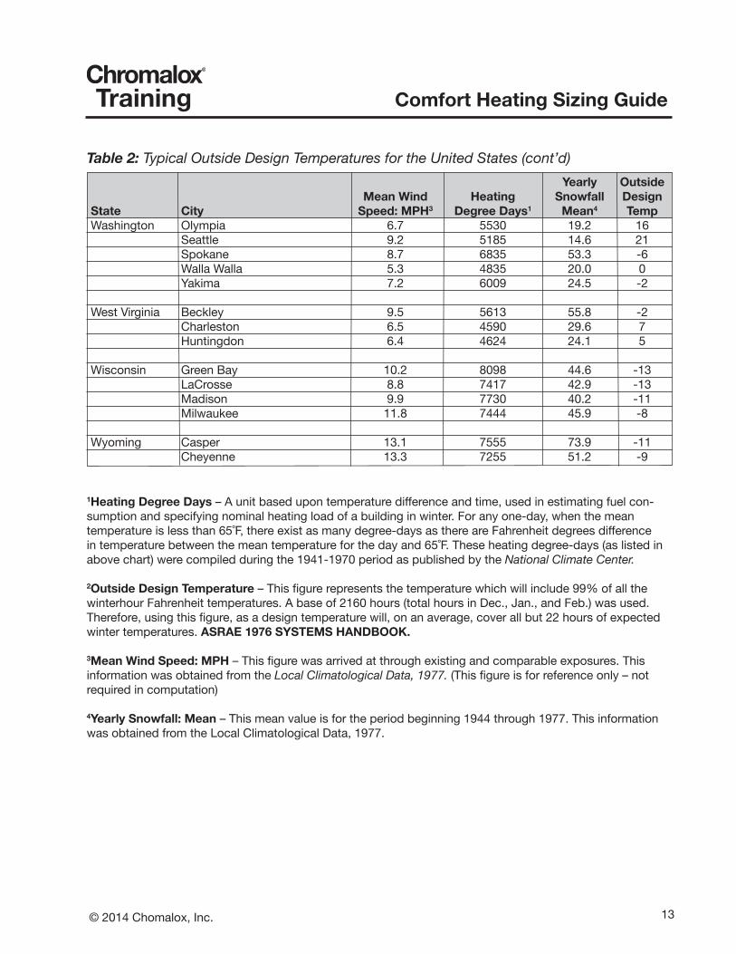
Table 2: Typical Outside Design Temperatures for the United States (cont’d) Yearly Outside Mean Wind Heating Snowfall DesignState City Speed: MPH3 Degree Days1 Mean4 TempWashington Olympia 6.7 5530 19.2 16 Seattle 9.2 5185 14.6 21 Spokane 8.7 6835 53.3 -6 Walla Walla 5.3 4835 20.0 0 Yakima 7.2 6009 24.5 -2
West Virginia Beckley 9.5 5613 55.8 -2 Charleston 6.5 4590 29.6 7 Huntingdon 6.4 4624 24.1 5
Wisconsin Green Bay 10.2 8098 44.6 -13 LaCrosse 8.8 7417 42.9 -13 Madison 9.9 7730 40.2 -11 Milwaukee 11.8 7444 45.9 -8
Wyoming Casper 13.1 7555 73.9 -11 Cheyenne 13.3 7255 51.2 -9
1Heating Degree Days – A unit based upon temperature difference and time, used in estimating fuel con-sumption and specifying nominal heating load of a building in winter. For any one-day, when the mean temperature is less than 65˚F, there exist as many degree-days as there are Fahrenheit degrees difference in temperature between the mean temperature for the day and 65˚F. These heating degree-days (as listed in above chart) were compiled during the 1941-1970 period as published by the National Climate Center.
2Outside Design Temperature – This figure represents the temperature which will include 99% of all the winterhour Fahrenheit temperatures. A base of 2160 hours (total hours in Dec., Jan., and Feb.) was used. Therefore, using this figure, as a design temperature will, on an average, cover all but 22 hours of expected winter temperatures. ASRAE 1976 SYSTEMS HANDBOOK.
3Mean Wind Speed: MPH – This figure was arrived at through existing and comparable exposures. Thisinformation was obtained from the Local Climatological Data, 1977. (This figure is for reference only – not required in computation)
4Yearly Snowfall: Mean – This mean value is for the period beginning 1944 through 1977. This information was obtained from the Local Climatological Data, 1977.

14 © 2014 Chomalox, Inc.
Comfort Heating Sizing GuideTraining
Electric Infrared Comfort Heating
HEATS PEOPLE WITHOUT HEATING AIRInfrared travels through space and is absorbed by people and objects in its path. The air does not absorb infrared energy. With convection heating the air itself is warmed and circulated, however, warm air always rises to the highest point of a building. With Infrared heating, the warmth is directed and concentrated at the floor and people level where it is really needed.
ZONE CONTROL FLEXIBILITYInfrared heating is not dependent upon air movement like convection heat. Infrared energy is absorbed solely at the area it is directed. Therefore, it is possible to divide any area into separate smaller zones while maintaining a different comfort level in each zone. For ex-ample, Zone A, with a high concentration of people, could be maintained at a 70 degree comfort level while at the same time Zone B, a storage area, could be kept at 55 degrees or even turned off completely.
REDUCED OPERATING COSTSThe previous statements are advantages in themselves; but combined, they account foran energy/fuel savings of up to 50 percent. Actual savings will vary from building tobuilding depending on factors such as insulation, ceiling height and type of construction.
INSTANT HEATElectric infrared produces virtually instant heat There is no need to wait for heat buildup. Turn the heaters on just prior to heating requirements.
STAGINGAnother unique control feature of electric infrared that increases comfort conditions and saves energy consumption is staging. Where most systems are either “fully ON” or “fully OFF” the staging feature allows only a portion of the equipment’s total capacity to be used. For example, a two-stage control would work as follows: During the first stage,one heat source in every fixture would be energized. During the second stage, two heat sources in every fixture would be energized. For further control sophistication, a large area can be both zoned and staged. These systems, then, allow a more consistent and uniform means of maintaining a specific comfort level and avoid the “peak & valley” syndrome.
15© 2014 Chomalox, Inc.
Comfort Heating Sizing GuideTraining
LOW MAINTENANCEElectric infrared is strictly a resistance type heat. There are no moving parts or motors to wear out; no air filters or lubrication required. Periodic cleaning of the reflectors and heat source replacement is all that will be required.
CLEANElectric infrared, like other forms of electric heating, is the cleanest method of heating. There are no by-products of combustion as with fossil fuel burning units. Electric infrared adds nothing to the air nor takes anything from it.
SAFE· No open flame· No moving parts to malfunction· No fuel lines to leak· No toxic by-products of combustion· UL available on some models
EFFICIENTElectric Heaters convert energy to heat at 100% efficiency.
Indoor Spot Heating
An indoor spot heating design will maintain an isolated comfort level within a larger andcooler area. The ambient temperature of the surrounding areas must be considered to help determine proper input to the work area. The ambient temperature in the area will not in-crease by the spot heating approach. Many times a series of spot heat areas can be incor-porated within the total area to avoid maintaining a higher ambient temperature throughout the building.
Comfort levels will depend on the intensity of the wattage delivered. Wattage should be sufficient to balance normal body heat losses, and will depend on ambient conditions, dress, and activity of the individual in the work area.
16 © 2014 Chomalox, Inc.
Comfort Heating Sizing GuideTraining
Since actual ambient temperatures are not maintained, several factors involved withindoor spot heating must be considered:
Figure 2: Typical Infrared Heating Pattern
1. Beam patterns should always cross approximately 5’ above floor level to provide even heat at the work area.
2. Avoid installing only one fixture directly over a person’s head at a workstation.
3. All spot heat applications, regardless of area size, should heat the person or object from two sides.
4. Fixtures should be mounted so that the long dimension of the heat pattern is parallel to the long dimensions of the area to be heated.
5. Spot heating systems can be controlled manually, or preferably, with a thermostat located away from the direct pattern of the heaters. Percentage timers may be used, but are not as effective.
6. Avoid mounting fixtures at heights less than 8’.
10’
1
FEET
HEAD
REFL60˚
TILT22˚
2
11.5’
. . . . . .
17© 2014 Chomalox, Inc.
Comfort Heating Sizing GuideTraining
The estimator must also have the following specific information available beforecalculating the heating load and fixture layout:
1. Design voltage and phase to be employed.
2. Minimum practical mounting height for the heating equipment.
3. Specific dimensions of the area to be heated.
4. Specific statement of the heating task including the design tempera-ture required.
The following procedures facilitate the calculation of the required infrared capacity and system layout of infrared heater fixtures.
Supplemental Spot Heating - Indoor
Consider these guidelines for spot heating (areas with length or width less than 50 feet).
1. Determine the coldest inside temperature the system must overcome. If freeze protec-tion is provided by another heating system, this temperature will be around 40˚Fahren-heit.
2. Determine the operational temperature desired. (That temperature which the customer would want if convection heating were installed. 70˚Fahrenheit is a nominal average.)
3. Subtract 1 from 2 to determine the increase in operational temperature (∆t0) expected from the infrared system. If drafts are present in the occupied area (air movement over 44 feet per minute velocity), wind shielding for the area occupants should be provided.
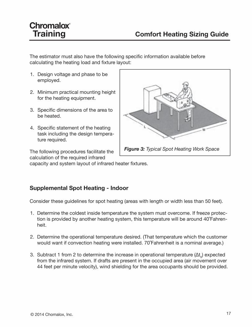
Figure 3: Typical Spot Heating Work Space
18 © 2014 Chomalox, Inc.
Comfort Heating Sizing GuideTraining
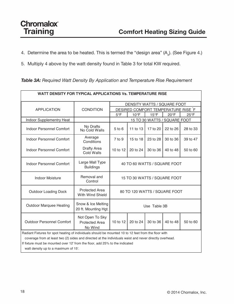
4. Determine the area to be heated. This is termed the “design area” (Ad). (See Figure 4.)
5. Multiply 4 above by the watt density found in Table 3 for total KW required.
Table 3A: Required Watt Density By Application and Temperature Rise Requirement
WATT DENSITY FOR TYPICAL APPLICATIONS Vs. TEMPERATURE RISE
APPLICATION CONDITION5°F 10°F 15°F 20°F 25°F
Indoor Supplementry Heat
Indoor Personnel Comfort No Drafts 5 to 6 11 to 13 17 to 20 22 to 26 28 to 33No Cold Walls
Indoor Personnel Comfort Average 7 to 9 15 to 18 23 to 28 30 to 36 39 to 47Conditions
Indoor Personnel Comfort Drafty Area 10 to 12 20 to 24 30 to 36 40 to 48 50 to 60Cold Walls
Indoor Personnel Comfort Large Mall Type 40 TO 60 WATTS / SQUARE FOOTBuildings
Indoor Moisture Removal and 15 TO 30 WATTS / SQUARE FOOTControl
Outdoor Loading Dock Protected Area 80 TO 120 WATTS / SQUARE FOOTWith Wind Shield
Outdoor Marquee Heating Snow & Ice Melting20 ft. Mounting Hgt.
Outdoor Personnel ComfortNot Open To Sky
10 to 12 20 to 24 30 to 36 40 to 48 50 to 60Protected AreaNo Wind
Radiant Fixtures for spot heating of individuals should be mounted 10 to 12 feet from the floor with coverage from at least two (2) sides and directed at the individuals waist and never directly overhead. If fixture must be mounted over 12' from the floor, add 25% to the indicated watt density up to a maximum of 15'.
DESIRED COMFORT TEMPERATURE RISE °F
15 TO 30 WATTS / SQUARE FOOT
Use Table 3B
DENSITY WATTS / SQUARE FOOT

19© 2014 Chomalox, Inc.
Comfort Heating Sizing GuideTraining
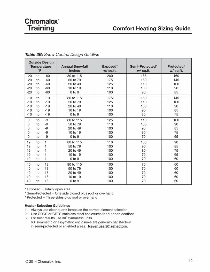
Table 3B: Snow Control Design Guidline
Outside Design Temperature Annual Snowfall Exposed* Semi-Protected* Protected* ˚F Inches w/sq.ft. w/sq.ft. w/sq.ft. -20 to -60 80 to 115 200 185 160 -20 to -60 50 to 79 175 160 145 -20 to -60 20 to 49 125 110 100 -20 to -60 10 to 19 110 100 90 -20 to -60 0 to 9 100 90 85 -10 to -19 80 to 115 175 160 145 -10 to -19 50 to 79 125 110 100 -10 to -19 20 to 49 110 100 90 -10 to -19 10 to 19 100 90 85 -10 to -19 0 to 9 100 80 75 0 to -9 80 to 115 125 110 100 0 to -9 50 to 79 110 100 90 0 to -9 20 to 49 100 90 85 0 to -9 10 to 19 100 80 75 0 to -9 0 to 9 100 70 65 19 to 1 80 to 115 110 100 90 19 to 1 50 to 79 100 90 85 19 to 1 20 to 49 100 80 75 19 to 1 10 to 19 100 70 65 19 to 1 0 to 9 100 70 60 40 to 18 80 to 115 100 70 60 40 to 18 50 to 79 100 70 60 40 to 18 20 to 49 100 70 60 40 to 18 10 to 19 100 70 60 40 to 18 0 to 9 100 70 60
* Exposed = Totally open area * Semi-Protected = One side closed plus roof or overhang * Protected = Three sides plus roof or overhang
Heater Selection Guidelines 1. Always use clear quartz lamps as the correct element selection2. Use CRDS or CRTS stainless steel enclosures for outdoor locations3. For best results use 30˚ symmetric units. 60˚ symmetric or assymetric enclosures are generally satisfactory in semi-protected or shielded areas. Neveruse90˚reflectors.
20 © 2014 Chomalox, Inc.
Comfort Heating Sizing GuideTraining
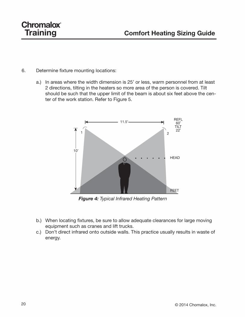
6. Determine fixture mounting locations:
a.) In areas where the width dimension is 25’ or less, warm personnel from at least 2 directions, tilting in the heaters so more area of the person is covered. Tilt should be such that the upper limit of the beam is about six feet above the cen-ter of the work station. Refer to Figure 5.
b.) When locating fixtures, be sure to allow adequate clearances for large moving equipment such as cranes and lift trucks.
c.) Don’t direct infrared onto outside walls. This practice usually results in waste of energy.
Figure 4: Typical Infrared Heating Pattern
10’
1
FEET
HEAD
REFL60˚
TILT22˚
2
11.5’
. . . . . .

21© 2014 Chomalox, Inc.
Comfort Heating Sizing GuideTraining
MOUNTINGHEIGHT
FW
W
WIDTH OFRADIATION PATTERN
W
W/2
W/2
L
FW
FLFIXTURELENGTH
Figure 5: Radiated Pattern Area
7. Tentatlively estimate the readiated pattern area. Add length of fixture to the fixture pattern (W) to establish pattern Length (L). Pattern area = L x W. See Figure 6. The formulas for the width and length of the pattern area are shown in figure 8.
Figure 6: Cross Coverage of the Radiation Pattern byAngling the Heater in a Supplemental Heat Application
HEIGHT (H)
PATTERN WIDTH (W)
(REFL) ANGLE

22 © 2014 Chomalox, Inc.
Comfort Heating Sizing GuideTraining
Pattern Width-Vertical Pattern Width- Angle Pattern Length
60° Sym-metrical
W=1.15H+FW 15° WA=1.25*H + FW22° WA=1.4*H + FW30° WA=1.7*H + FW
L = W + FL
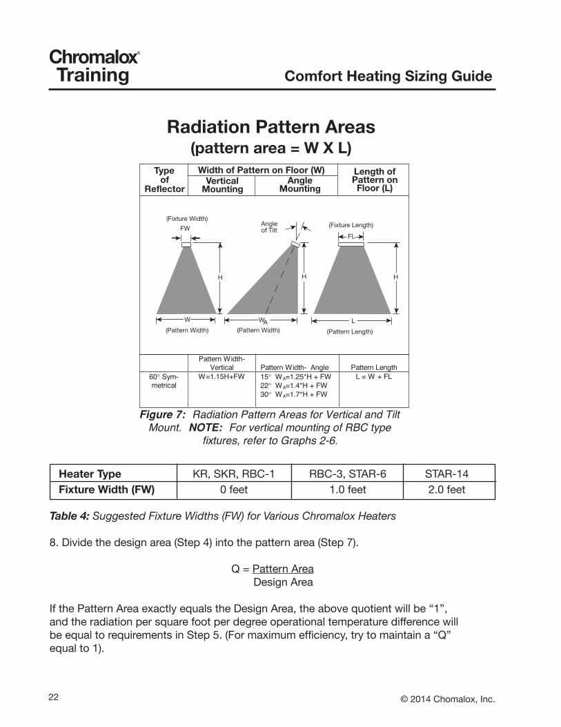
Figure 7: Radiation Pattern Areas for Vertical and TiltMount. NOTE: For vertical mounting of RBC type
fixtures, refer to Graphs 2-6.
Radiation Pattern Areas(pattern area = W X L)
Typeof
Reflector
Width of Pattern on Floor (W)Vertical
MountingAngle
Mounting
Length ofPattern onFloor (L)
(Fixture Width)
FWAngleof Tilt
(Fixture Length)
(Pattern Width) (Pattern Width) (Pattern Length)
H
W
H
WA
FL
H
L
Heater Type KR, SKR, RBC-1 RBC-3, STAR-6 STAR-14 Fixture Width (FW) 0 feet 1.0 feet 2.0 feet
Table 4: Suggested Fixture Widths (FW) for Various Chromalox Heaters
8. Divide the design area (Step 4) into the pattern area (Step 7).
Q = Pattern Area Design Area
If the Pattern Area exactly equals the Design Area, the above quotient will be “1”,and the radiation per square foot per degree operational temperature difference willbe equal to requirements in Step 5. (For maximum efficiency, try to maintain a “Q”equal to 1).

23© 2014 Chomalox, Inc.
Comfort Heating Sizing GuideTraining
METAL SHEATH ELEMENT RADIANT EFFICIENCY 60% MountingHeight Area(WxL) Square 1KW 1.5KW 2KW 2.5KW Ft. Ft. Ft w/sq.ft. w/sq.ft. w/sq.ft. w/sq.ft. 8 16 X 16 256 2.3 3.5 4.7 5.9 9 18 X 18 324 1.9 2.8 3.7 4.6 10 20 X 20 400 1.5 2.3 3.0 3.8 11 22 X 22 484 1.2 1.9 2.5 3.1 12 24 X 24 576 1.0 1.6 2.1 2.6 13 26 X 26 676 0.9 1.3 1.8 2.2 14 28 X 28 784 0.8 1.1 1.5 1.9 15 30 X 30 900 0.7 1.0 1.3 1.7
Chart 1: 90˚ Symmetrical Reflectors for Single Element RBC-1 Infrared Heaters
METAL SHEATH ELEMENT RADIANT EFFICIENCY 60%MountingHeight Area(WxL) Square 1.5KW 2KW 4.5KW 6KW 13.5KW Ft. Ft. Ft. w/sq.ft. w/sq.ft. w/sq.ft. w/sq.ft. w/sq.ft. 8 9.2 X 9.2 85 10.6 14.2 31.9 42.5 95.7 9 10.35 X 10.35 107 8.4 11.2 25.2 33.6 75.6 10 11.5 X 11.5 132 6.8 9.1 20.4 27.2 61.2 11 12.65 X 12.65 160 5.6 7.5 16.9 22.5 50.6 12 13.8 X 13.8 190 4.7 6.3 14.2 18.9 42.5 13 14.95 X 14.95 224 4.0 5.4 12.1 16.1 36.2 14 16.1 X 16.1 259 3.5 4.6 10.4 13.9 31.2 15 17.25 X 17.25 298 3.0 4.0 9.1 12.1 27.2 16 18.4 X 18.4 339 2.7 3.5 8.0 10.6 23.9 17 19.55 X 19.55 382 2.4 3.1 7.1 9.4 21.2 18 20.7 X 20.7 428 2.1 2.8 6.3 8.4 18.9 19 21.85 X 21.85 477 1.9 2.5 5.7 7.5 17.0 20 23 X 23 529 1.7 2.3 5.1 6.8 15.3 21 24.15 X 24.15 583 1.5 2.1 4.6 6.2 13.9 22 25.3 X 25.3 640 1.4 1.9 4.2 5.6 12.7 23 26.45 X 26.45 700 1.3 1.7 3.9 5.1 11.6 24 27.6 X 27.6 762 1.2 1.6 3.5 4.7 10.6
Chart 2: 60˚ Symmetrical Deflectors for 1 & 3 Element STAR Infrared Heaters
24 © 2014 Chomalox, Inc.
Comfort Heating Sizing GuideTraining
METAL SHEATH ELEMENT RADIANT EFFICIENCY 60%
24” Enclosure 33” Enclosure 46” Enclosure 2 Element 3 Element 2 Element 3 Element 2 Element 3 ElementMountingHeight Area(WXL) Square 1.6KW 2.5KW 3KW 4.5KW 4KW 6KW Ft. Ft. Ft. w/sq.ft. w/sq.ft. w/sq.ft. w/sq.ft. w/sq.ft. w/sq.ft. 5 10 X 10 100 9.6 15.0 18.0 27.0 24.0 36.0 6 12 X 12 144 6.7 10.4 12.5 18.8 16.7 25.0 7 14 X 14 196 4.9 7.7 9.2 13.8 12.2 18.4 8 16 X 16 256 3.8 5.9 7.0 10.5 9.4 14.1 9 18 X 18 324 3.0 4.6 5.6 8.3 7.4 11.1 10 20 X 20 400 2.4 3.8 4.5 6.8 6.0 9.0 11 22 X 22 484 2.0 3.1 3.7 5.6 5.0 7.4 12 24 X 24 576 1.7 2.6 3.1 4.7 4.2 6.3 13 26 X 26 676 1.4 2.2 2.7 4.0 3.6 5.3 14 28 X 28 784 1.2 1.9 2.3 3.4 3.1 4.6 15 30 X 30 900 1.1 1.7 2.0 3.0 2.7 4.0 16 32 X 32 1024 1.5 1.8 2.6 2.3 3.5 17 34 X 34 1156 1.3 1.6 2.3 2.1 3.1 18 36 X 36 1296 1.2 1.4 2.1 1.9 2.8 19 38 X 38 1444 1.0 1.2 1.9 1.7 2.5 20 40 X 40 1600 1.1 1.7 1.5 2.3 QUARTZ TUBE ELEMENT RADIANT EFFICIENCY 60% 24” Enclosure 33” Enclosure 46” Enclosure 2 Element 3 Element 2 Element 3 Element 2 Element 3 Element MountingHeight Area(WXL) Square 2KW 3KW 4KW 6KW 6KW 9KW Ft. Ft. Ft. w/sq.ft. w/sq.ft. w/sq.ft. w/sq.ft. w/sq.ft. w/sq.ft. 5 10 X 10 100 16.0 24.0 32.0 48.0 48.0 72.0 6 12 X 12 144 11.1 16.7 22.2 33.3 33.3 50.0 7 14 X 14 196 8.2 7.7 16.3 24.5 24.5 36.7 8 16 X 16 256 6.3 12.2 12.5 18.8 18.8 28.1 9 18 X 18 324 4.9 9.4 9.9 14.8 14.8 22.2 10 20 X 20 400 4.0 6.0 8.0 12.0 12.0 18.0 11 22 X 22 484 3.3 5.0 6.6 9.9 9.9 14.9 12 24 X 24 576 2.8 4.2 5.6 8.3 8.3 12.5 13 26 X 26 676 2.4 3.6 4.7 7.1 7.1 10.7 14 28 X 28 784 2.0 3.1 4.1 6.1 6.1 9.2 15 30 X 30 900 1.8 2.7 3.6 5.3 5.3 8.0 16 32 X 32 1024 1.6 2.3 3.1 4.7 4.7 7.0 17 34 X 34 1156 1.4 2.1 2.8 4.2 4.2 6.2 18 36 X 36 1296 1.2 1.9 2.5 3.7 3.7 5.6 19 38 X 38 1444 1.1 1.7 2.2 3.3 3.3 5.0 20 40 X 40 1600 1.0 1.5 2.0 3.0 3.0 4.5 QUARTZ TUBE ELEMENT RADIANT EFFICIENCY 60% 24” Enclosure 33” Enclosure 46” Enclosure 2 Element 3 Element 2 Element 3 Element 2 Element 3 ElementMountingHeight Area(WXL) Square 3.2KW 4.8KW 5KW 7.5KW 7.3KW 10.95KW Ft. Ft. Ft. w/sq.ft. w/sq.ft. w/sq.ft. w/sq.ft. w/sq.ft. w/sq.ft. 5 10 X 10 100 25.6 38.4 40.0 60.0 58.4 87.6 6 12 X 12 144 17.8 26.7 27.8 41.7 40.6 60.8 7 14 X 14 196 13.1 19.6 20.4 30.6 29.8 44.7 8 16 X 16 256 10.0 15.0 15.6 23.4 22.8 34.2 9 18 X 18 324 7.9 11.9 12.3 18.5 18.0 27.0 10 20 X 20 400 6.4 9.6 10.0 15.0 14.6 21.9 11 22 X 22 484 5.3 7.9 8.3 12.4 12.1 18.1 12 24 X 24 576 4.4 6.7 6.9 10.4 10.1 15.2 13 26 X 26 676 3.8 5.7 5.9 8.9 8.6 13.0 14 28 X 28 784 3.3 4.9 5.1 7.7 7.4 11.2 15 30 X 30 900 2.8 4.3 4.4 6.7 6.5 9.7 16 32 X 32 1024 2.5 3.8 3.9 5.9 5.7 8.6 17 34 X 34 1156 2.2 3.3 3.5 5.2 5.1 7.6 18 36 X 36 1296 2.0 3.0 3.1 4.6 4.5 6.8 19 38 X 38 1444 1.8 2.7 2.8 4.2 4.0 6.1 20 40 X 40 1600 1.6 2.4 2.5 3.8 3.7 5.5
Chart 3: 90˚ Symmetrical Reflectors for 2 & 3 Element High-Intensity Infrared Heaters
25© 2014 Chomalox, Inc.
Comfort Heating Sizing GuideTraining
METAL SHEATH ELEMENT RADIANT EFFICIENCY 60%
24” Enclosure 33” Enclosure 46” Enclosure 2 Element 3 Element 2 Element 3 Element 2 Element 3 ElementMountingHeight Area(WXL) Square 1.6KW 2.5KW 3KW 4.5KW 4KW 6KW Ft. Ft. Ft. w/sq.ft. w/sq.ft. w/sq.ft. w/sq.ft. w/sq.ft. w/sq.ft. 5 5.8 X 10 57.5 16.7 26.1 31.3 47.0 41.7 62.6 6 6.9 X 12 82.8 11.6 18.1 21.7 32.6 29.0 43.5 7 8.1 X 14 112.7 8.5 13.3 16.0 24.0 21.3 31.9 8 9.2 X 16 147.2 6.5 10.2 12.2 18.3 16.3 24.5 9 10.4 X 18 186.3 5.2 8.1 9.7 14.5 12.9 19.3 10 11.5 X 20 230.0 4.2 6.5 7.8 11.7 10.4 15.7 11 12.7 X 22 278.3 3.4 5.4 6.5 9.7 8.6 12.9 12 13.8 X 24 331.2 2.9 4.5 5.4 8.2 7.2 10.9 13 15.0 X 26 388.7 2.5 3.9 4.6 6.9 6.2 9.3 14 16.1 X 28 450.8 2.1 3.3 4.0 6.0 5.3 8.0 15 17.3 X 30 517.5 1.9 2.9 3.5 5.2 4.6 7.0 16 18.4 X 32 588.8 1.6 2.5 3.1 4.6 4.1 6.1 17 19.6 X 34 664.7 1.4 2.3 2.7 4.1 3.6 5.4 18 20.7 X 36 745.2 1.3 2.0 2.4 3.6 3.2 4.8 19 21.9 X 38 830.3 1.2 1.8 2.2 3.3 2.9 4.3 20 23.0 X 40 920.0 1.0 1.6 2.0 2.9 2.6 3.9 QUARTZ TUBE ELEMENT RADIANT EFFICIENCY 60% 24” Enclosure 33” Enclosure 46” Enclosure 2 Element 3 Element 2 Element 3 Element 2 Element 3 ElementMountingHeight Area(WXL) Square 2KW 3KW 4KW 6KW 6KW 9KW Ft. Ft. Ft. w/sq.ft. w/sq.ft. w/sq.ft. w/sq.ft. w/sq.ft. w/sq.ft. 5 5.8 X 10 57.5 27.8 41.7 55.7 83.5 83.5 125.2 6 6.9 X 12 82.8 19.3 29.0 38.6 58.0 58.0 87.0 7 8.1 X 14 112.7 14.2 21.3 28.4 42.6 42.6 63.9 8 9.2 X 16 147.2 10.9 16.3 21.7 32.6 32.6 48.9 9 10.4 X 18 186.3 8.6 12.9 17.2 25.8 25.8 38.6 10 11.5 X 20 230.0 7.0 10.4 13.9 20.9 20.9 31.3 11 12.7 X 22 278.3 5.7 8.6 11.5 17.2 17.2 25.9 12 13.8 X 24 331.2 4.8 7.2 9.7 14.5 14.5 21.7 13 15.0 X 26 388.7 4.1 6.2 8.2 12.3 12.3 18.5 14 16.1 X 28 450.8 3.5 5.3 7.1 10.6 10.6 16.0 15 17.3 X 30 517.5 3.1 4.6 6.2 9.3 9.3 13.9 16 18.4 X 32 588.8 2.7 4.1 5.4 8.2 8.2 12.2 17 19.6 X 34 664.7 2.4 3.6 4.8 7.2 7.2 10.8 18 20.7 X 36 745.2 2.1 3.2 4.3 6.4 6.4 9.7 19 21.9 X 38 830.3 1.9 2.9 3.9 5.8 5.8 8.7 20 23.0 X 40 920.0 1.7 2.6 3.5 5.2 5.2 7.8
QUARTZ TUBE ELEMENT RADIANT EFFICIENCY 60% 24” Enclosure 33” Enclosure 46” Enclosure 2 Element 3 Element 2 Element 3 Element 2 Element 3 ElementMountingHeight Area(WXL) Square 3.2KW 4.8KW 5KW 7.5KW 7.3KW 10.95KW Ft. Ft. Ft. w/sq.ft. w/sq.ft. w/sq.ft. w/sq.ft. w/sq.ft. w/sq.ft. 5 5.8 X 10 57.5 44.5 66.8 69.6 104.3 101.6 152.3 6 6.9 X 12 82.8 30.9 46.4 48.3 72.5 70.5 105.8 7 8.1 X 14 112.7 22.7 34.1 35.5 53.2 51.8 77.7 8 9.2 X 16 147.2 17.4 26.1 27.2 40.8 39.7 59.5 9 10.4 X 18 186.3 13.7 20.6 21.5 32.2 31.3 47.0 10 11.5 X 20 230.0 11.1 16.7 17.4 26.1 25.4 38.1 11 12.7 X 22 278.3 9.2 13.8 14.4 21.6 21.0 31.5 12 13.8 X 24 331.2 7.7 11.6 12.1 18.1 17.6 26.4 13 15.0 X 26 388.7 6.6 9.9 10.3 15.4 15.0 22.5 14 16.1 X 28 450.8 5.7 8.5 8.9 13.3 13.0 19.4 15 17.3 X 30 517.5 4.9 7.4 7.7 11.6 11.3 16.9 16 18.4 X 32 588.8 4.3 6.5 6.8 10.2 9.9 14.9 17 19.6 X 34 664.7 3.9 5.8 6.0 9.0 8.8 13.2 18 20.7 X 36 745.2 3.4 5.2 5.4 8.1 7.8 11.8 19 21.9 X 38 830.3 3.1 4.6 4.8 7.2 7.0 10.6 20 23.0 X 40 920.0 2.8 4.2 4.3 6.5 6.3 9.5
Chart 4: 60˚ Symmetrical Reflectors for 2 & 3 Element High-Intensity Infrared Heaters
26 © 2014 Chomalox, Inc.
Comfort Heating Sizing GuideTraining
METAL SHEATH ELEMENT RADIANT EFFICIENCY 60%
24” Enclosure 33” Enclosure 46” Enclosure 2 Element 3 Element 2 Element 3 Element 2 Element 3 ElementMountingHeight Area(WXL) Square 1.6KW 2.5KW 3KW 4.5KW 4KW 6KW Ft. Ft. Ft. w/sq.ft. w/sq.ft. w/sq.ft. w/sq.ft. w/sq.ft. w/sq.ft. 5 2.7 X 10 27.0 35.6 55.6 66.7 100.0 88.9 133.3 6 3.2 X 12 38.9 24.7 38.6 46.3 69.4 61.7 92.6 7 3.8 X 14 52.9 18.1 28.3 34.0 51.0 45.4 68.0 8 4.3 X 16 69.1 13.9 21.7 26.0 39.1 34.7 52.1 9 4.9 X 18 87.5 11.0 17.1 20.6 30.9 27.4 41.2 10 5.4 X 20 108.0 8.9 13.9 16.7 25.0 22.2 33.3 11 5.9 X 22 130.7 7.3 11.5 13.8 20.7 18.4 27.5 12 6.5 X 24 155.5 6.2 9.6 11.6 17.4 15.4 23.1 13 7.0 X 26 182.5 5.3 8.2 9.9 14.8 13.1 19.7 14 7.6 X 28 211.7 4.5 7.1 8.5 12.8 11.3 17.0 15 8.1 X 30 243.0 4.0 6.2 7.4 11.1 9.9 14.8 16 8.6 X 32 276.5 3.5 5.4 6.5 9.8 8.7 13.0 17 9.2 X 34 312.1 3.1 4.8 5.8 8.7 7.7 11.5 18 9.7 X 36 349.9 2.7 4.3 5.1 7.7 6.9 10.3 19 10.3 X 38 389.9 2.5 3.8 4.6 6.9 6.2 9.2 20 10.8 X 40 432.0 2.2 3.5 4.2 6.3 5.6 8.3 QUARTZ TUBE ELEMENT RADIANT EFFICIENCY 60% 24” Enclosure 33” Enclosure 46” Enclosure 2 Element 3 Element 2 Element 3 Element 2 Element 3 ElementMountingHeight Area(WXL) Square 2KW 3KW 4KW 6KW 6KW 9KW Ft. Ft. Ft. w/sq.ft. w/sq.ft. w/sq.ft. w/sq.ft. w/sq.ft. w/sq.ft. 5 2.7 X 10 27.0 59.3 88.9 118.5 177.8 177.8 266.7 6 3.2 X 12 38.9 41.2 61.7 82.3 123.5 123.5 185.2 7 3.8 X 14 52.9 30.2 45.4 60.5 90.7 90.7 136.1 8 4.3 X 16 69.1 23.1 34.7 46.3 69.4 69.4 104.2 9 4.9 X 18 87.5 18.3 27.4 36.6 54.9 54.9 82.3 10 5.4 X 20 108.0 14.8 22.2 29.6 44.4 44.4 66.7 11 5.9 X 22 130.7 12.2 18.4 24.5 36.7 36.7 55.1 12 6.5 X 24 155.5 10.3 15.4 20.6 30.9 30.9 46.3 13 7.0 X 26 182.5 8.8 13.1 17.5 26.3 26.3 39.4 14 7.6 X 28 211.7 7.6 11.3 15.1 22.7 22.7 34.0 15 8.1 X 30 243.0 6.6 9.9 13.2 19.8 19.8 29.6 16 8.6 X 32 276.5 5.8 8.7 11.6 17.4 17.4 26.0 17 9.2 X 34 312.1 5.1 7.7 10.3 15.4 15.4 23.1 18 9.7 X 36 349.9 4.6 6.9 9.1 13.7 13.7 20.6 19 10.3 X 38 389.9 4.1 6.2 8.2 12.3 12.3 18.5 20 10.8 X 40 432.0 3.7 5.6 7.4 11.1 11.1 16.7
QUARTZ TUBE ELEMENT RADIANT EFFICIENCY 60% 24” Enclosure 33” Enclosure 46” Enclosure 2 Element 3 Element 2 Element 3 Element 2 Element 3 ElementMountingHeight Area(WXL) Square 3.2KW 4.8KW 5KW 7.5KW 7.3KW 10.95KW Ft. Ft. Ft. w/sq.ft. w/sq.ft. w/sq.ft. w/sq.ft. w/sq.ft. w/sq.ft. 5 2.7 X 10 27.0 94.8 142.2 148.1 222.2 216.3 324.4 6 3.2 X 12 38.9 65.8 98.8 102.9 154.3 150.2 225.3 7 3.8 X 14 52.9 48.4 72.6 75.6 113.4 110.4 165.5 8 4.3 X 16 69.1 37.0 55.6 57.9 86.8 84.5 126.7 9 4.9 X 18 87.5 29.3 43.9 45.7 68.6 66.8 100.1 10 5.4 X 20 108.0 23.7 35.6 37.0 55.6 54.1 81.1 11 5.9 X 22 130.7 19.6 29.4 30.6 45.9 44.7 67.0 12 6.5 X 24 155.5 16.5 24.7 25.7 38.6 37.6 56.3 13 7.0 X 26 182.5 14.0 21.0 21.9 32.9 32.0 48.0 14 7.6 X 28 211.7 12.1 18.1 18.9 28.3 27.6 41.4 15 8.1 X 30 243.0 10.5 15.8 16.5 24.7 24.0 36.0 16 8.6 X 32 276.5 9.3 13.9 14.5 21.7 21.1 31.7 17 9.2 X 34 312.1 8.2 12.3 12.8 19.2 18.7 28.1 18 9.7 X 36 349.9 7.3 11.0 11.4 17.1 16.7 25.0 19 10.3 X 38 389.9 6.6 9.8 10.3 15.4 15.0 22.5 20 10.8 X 40 432.0 5.9 8.9 9.3 13.9 13.5 20.3
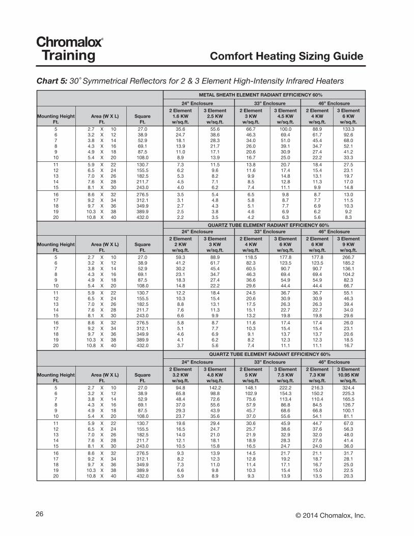
Chart 5: 30˚ Symmetrical Reflectors for 2 & 3 Element High-Intensity Infrared Heaters

27© 2014 Chomalox, Inc.
Comfort Heating Sizing GuideTraining
METAL SHEATH ELEMENT RADIANT EFFICIENCY 60%
24” Enclosure 33” Enclosure 46” Enclosure 2 Element 3 Element 2 Element 3 Element 2 Element 3 ElementMountingHeight Area(WXL) Square 1.6KW 2.5KW 3KW 4.5KW 4KW 6KW Ft. Ft. Ft. w/sq.ft. w/sq.ft. w/sq.ft. w/sq.ft. w/sq.ft. w/sq.ft. 5 6 X 10 63 15.4 24.0 28.8 43.2 38.4 57.6 6 8 X 12 90 10.7 16.7 20.0 30.0 26.7 40.0 7 9 X 14 123 7.8 12.2 14.7 22.0 19.6 29.4 8 10 X 16 160 6.0 9.4 11.3 16.9 15.0 22.5 9 11 X 18 203 4.7 7.4 8.9 13.3 11.9 17.8 10 13 X 20 250 3.8 6.0 7.2 10.8 9.6 14.4 11 14 X 22 303 3.2 5.0 6.0 8.9 7.9 11.9 12 15 X 24 360 2.7 4.2 5.0 7.5 6.7 10.0 13 16 X 26 423 2.3 3.6 4.3 6.4 5.7 8.5 14 18 X 28 490 2.0 3.1 3.7 5.5 4.9 7.3 15 19 X 30 563 1.7 2.7 3.2 4.8 4.3 6.4 16 20 X 32 640 1.5 2.3 2.8 4.2 3.8 5.6 17 21 X 34 723 1.3 2.1 2.5 3.7 3.3 5.0 18 23 X 36 810 1.2 1.9 2.2 3.3 3.0 4.4 19 24 X 38 903 1.1 1.7 2.0 3.0 2.7 4.0 20 25 X 40 1000 1.0 1.5 1.8 2.7 2.4 3.6 QUARTZ TUBE ELEMENT RADIANT EFFICIENCY 60% 24” Enclosure 33” Enclosure 46” Enclosure 2 Element 3 Element 2 Element 3 Element 2 Element 3 ElementMountingHeight Area(WXL) Square 2KW 3KW 4KW 6KW 6KW 9KW Ft. Ft. Ft. w/sq.ft. w/sq.ft. w/sq.ft. w/sq.ft. w/sq.ft. w/sq.ft. 5 6 X 10 63 25.6 38.4 51.2 76.8 76.8 115.2 6 8 X 12 90 17.8 26.7 35.6 53.3 53.3 80.0 7 9 X 14 123 13.1 19.6 26.1 39.2 39.2 58.8 8 10 X 16 160 10.0 15.0 20.0 30.0 30.0 45.0 9 11 X 18 203 7.9 11.9 15.8 23.7 23.7 35.6 10 13 X 20 250 6.4 9.6 12.8 19.2 19.2 28.8 11 14 X 22 303 5.3 7.9 10.6 15.9 15.9 23.8 12 15 X 24 360 4.4 6.7 8.9 13.3 13.3 20.0 13 16 X 26 423 3.8 5.7 7.6 11.4 11.4 17.0 14 18 X 28 490 3.3 4.9 6.5 9.8 9.8 14.7 15 19 X 30 563 2.8 4.3 5.7 8.5 8.5 12.8 16 20 X 32 640 2.5 3.8 5.0 7.5 7.5 11.3 17 21 X 34 723 2.2 3.3 4.4 6.6 6.6 10.0 18 23 X 36 810 2.0 3.0 4.0 5.9 5.9 8.9 19 24 X 38 903 1.8 2.7 3.5 5.3 5.3 8.0 20 25 X 40 1000 1.6 2.4 3.2 4.8 4.8 7.2
QUARTZ TUBE ELEMENT RADIANT EFFICIENCY 60% 24” Enclosure 33” Enclosure 46” Enclosure 2 Element 3 Element 2 Element 3 Element 2 Element 3 ElementMountingHeight Area(WXL) Square 3.2KW 4.8KW 5KW 7.5KW 7.3KW 10.95KW Ft. Ft. Ft. w/sq.ft. w/sq.ft. w/sq.ft. w/sq.ft. w/sq.ft. w/sq.ft. 5 6 X 10 63 41.0 61.4 64.0 96.0 93.4 140.2 6 8 X 12 90 28.4 42.7 44.4 66.7 64.9 97.3 7 9 X 14 123 20.9 31.3 32.7 49.0 47.7 71.5 8 10 X 16 160 16.0 24.0 25.0 37.5 36.5 54.8 9 11 X 18 203 12.6 19.0 19.8 29.6 28.8 43.3 10 13 X 20 250 10.2 15.4 16.0 24.0 23.4 35.0 11 14 X 22 303 8.5 12.7 13.2 19.8 19.3 29.0 12 15 X 24 360 7.1 10.7 11.1 16.7 16.2 24.3 13 16 X 26 423 6.1 9.1 9.5 14.2 13.8 20.7 14 18 X 28 490 5.2 7.8 8.2 12.2 11.9 17.9 15 19 X 30 563 4.6 6.8 7.1 10.7 10.4 15.6 16 20 X 32 640 4.0 6.0 6.3 9.4 9.1 13.7 17 21 X 34 723 3.5 5.3 5.5 8.3 8.1 12.1 18 23 X 36 810 3.2 4.7 4.9 7.4 7.2 10.8 9 24 X 38 903 2.8 4.3 4.4 6.6 6.5 9.7 20 25 X 40 1000 2.6 3.8 4.0 6.0 5.8 8.8
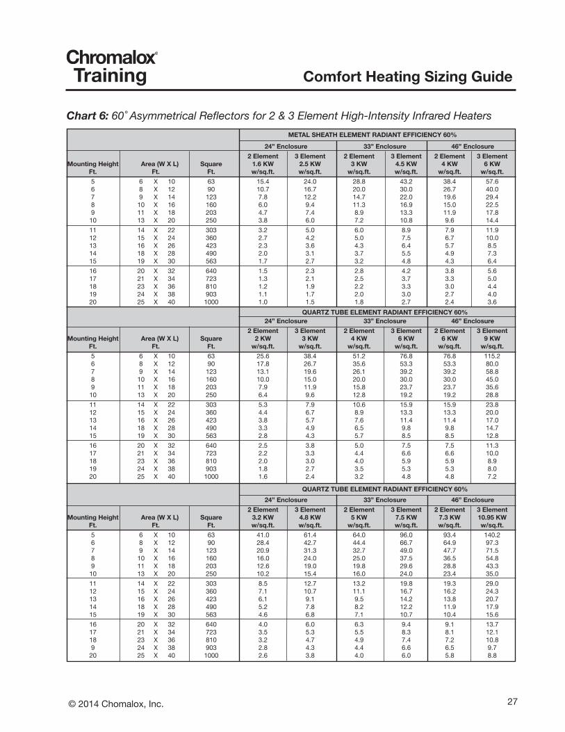
Chart 6: 60˚ Asymmetrical Reflectors for 2 & 3 Element High-Intensity Infrared Heaters
28 © 2014 Chomalox, Inc.
Comfort Heating Sizing GuideTraining
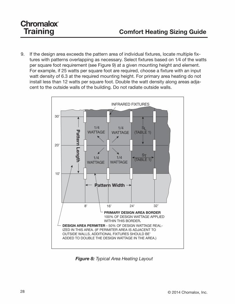
9. If the design area exceeds the pattern area of individual fixtures, locate multiple fix-tures with patterns overlapping as necessary. Select fixtures based on 1⁄4 of the watts per square foot requirement (see Figure 9) at a given mounting height and element. For example, if 25 watts per square foot are required, choose a fixture with an input watt density of 6.3 at the required mounting height. For primary area heating do not install less than 12 watts per square foot. Double the watt density along areas adja-cent to the outside walls of the building. Do not radiate outside walls.
Figure 8: Typical Area Heating Layout
INFRARED FIXTURES
1/4WATTAGE
1/4WATTAGE
1/4WATTAGE
1/4WATTAGE
S(TABLE 1)
T
Pattern Width
Pattern Leng
th
PRIMARY DESIGN AREA BORDER100% OF DESIGN WATTAGE APPLIEDWITHIN THIS BORDER.
S(TABLE 1)
L
DESIGN AREA PERMITER - 50% OF DESIGN WATTAGE REAL-IZED IN THIS AREA. (IF PERIMITER AREA IS ADJACENT TOOUTSIDE WALLS, ADDITIONAL FIXTURES SHOULD BE’ADDED TO DOUBLE THE DESIGN WATTAGE IN THE AREA.)
8’ 16’ 24’ 32’
10’
20’
30’

29© 2014 Chomalox, Inc.
Comfort Heating Sizing GuideTraining
10. Choose specific fixtures that meet the heating requirements noting that half the wattage should be on each side of the workstation in the design area. Space the heaters to provide a 50% overlap using the formula provided in Figure 8. See Figure 7 for typical lay-out.
11. To provide better control of comfort it is usually desirable to divide the total heat required into two or three circuits so that each fixture or heating element circuit can be switched on in sequence, as the ambient conditions require. It may, therefore, require three fixtures on each side to provide maxi-mum comfort in a spot heating appli-cation.
Figure 9: Recommended spacing for 50% overlap
Recommended Fixture Spacing
NOTES: Longitudinal spacing to border of design area = SL/2Travers spacing to border of design areas = SL/2 (exceptionfixtures angled toward a work station have no definite locationwith respect to the border.)
(TraverseSpacing)
(LongitudinalSpacing)
(Pattern Width) (Pattern Length)
H(Mounting
Height)
FLFixtureLength
reflectorangle
transversespacing (SL)
reflectorangle
longitudinalspacing (SL)
60˚ 0.58H 60˚ W + FL
W L
STSL
transverse spacing forvertically mounted fixtures
Longitudinal spacing forvertical or angledmounted fixtures

30 © 2014 Chomalox, Inc.
Comfort Heating Sizing GuideTraining
CHROMALOXGeneral Industrial Sizing Guide
Heat Loss Calculation- Indoor
Job Name: Date:Location: Room:
Bid Number: Reference:
Voltage: V Phase:
Room SizeLength: ft. Width: ft. Ceiling Height: ft.
Total Square Footage: square feet
Heater Mounting Height: ft.
Design InformationCeiling R-Factor: Outside Design Temperature: F
Wall R-Factor: Desired Inside Temperature: FTemperature Rise: F
Air Changes Per Hour: cubic foot per hour
CalculationItem Area sq-ft X U-Factor = BTU/Hr/Degree FWindows sq-ft X =
Doors sq-ft X =Net Wall sq-ft X =
Roof sq-ft X =Floor Perimeter * ft X =
Item A TOTAL = BTU/Hr/degree F* For floor perimeter use U-factor of 1.2, 0.7, or 0.6 for exposed, 1" insulation, or 2" insulation respectively
Air Change Loss Cubic foot per hour X 0.019 BTU/cubic ft. = BTU/hr/degree FItem B cubic ft./hr X 0.019 BTU/cubic ft. =
TOTAL Item A + Item B = BTU/Hr/degree F
Item C Convert to Watts = Total / 3.412 = Watts/Hr/degree F
TOTAL HEATING REQUIREMENTItem C x Temperature Rise = Watts/Hr
Watts/Hr/degree F X degree F =Total Watts/Hr.
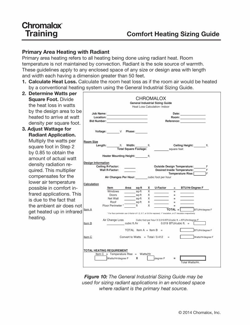
Primary Area Heating with RadiantPrimary area heating refers to all heating being done using radiant heat. Roomtemperature is not maintained by convection. Radiant is the sole source of warmth.These guidelines apply to any enclosed space of any size or design area with lengthand width each having a dimension greater than 50 feet.1. Calculate Heat Loss. Calculate the room heat loss as if the room air would be heated
by a conventional heating system using the General Industrial Sizing Guide.2. Determine Watts per
SquareFoot. Divide the heat loss in watts by the design area to be heated to arrive at watt density per square foot.
3. Adjust Wattage for Radiant Application. Multiply the watts per square foot in Step 2 by 0.85 to obtain the amount of actual watt density radiation re-quired. This multiplier compensates for the lower air temperature possible in comfort in-frared applications. This is due to the fact that the ambient air does not get heated up in infrared heating.
Figure 10: The General Industrial Sizing Guide may be used for sizing radiant applications in an enclosed space where radiant is the primary heat source.
Related Documents