Quick Table of Contents Introduction ..................................................................................................... 1 Electric Power System.................................................................................... 7 Heating and Air Conditioning System......................................................... 25 Troubleshooting ............................................................................................ 41

Welcome message from author
This document is posted to help you gain knowledge. Please leave a comment to let me know what you think about it! Share it to your friends and learn new things together.
Transcript

Quick Table of Contents
Introduction ..................................................................................................... 1
Electric Power System.................................................................................... 7
Heating and Air Conditioning System......................................................... 25
.................................... 41
Comfort_Class_System_OM.book Page 1 Thursday, November 1, 2007 1:12 PM
Troubleshooting........................................................

Comfort_Class_System_OM.book Page 2 Thursday, November 1, 2007 1:12 PM

Safety Signals
– 1 –
TION
see this symbol and word, the message that fol-specially vital. This signals something that canry or even death. This message will tell you what
d is, what can happen if you don’t heed the warn-ow to avoid it. For example:
bol and word signals something that could dam-vehicle. For example:
ARNING:
ARNING! Do not carry additional fuel con-iners in your vehicle. Fuel containers, eitherll or empty, may leak, explode, and cause ored a fire. Do not carry extra fuel containers.ven empty ones are dangerous.
AUTION:
AUTION: Continuing to operate your vehicleith insufficient oil pressure will cause seriousngine damage.
Comfort_Class_System_OM.book Page 1 Thursday, November 1, 2007 1:12 PM
PART 1: INTRODUCTION
R(09/07) Y53-6017
Figure -1
PART 1: INTRODUC
Safety SignalsA number of alerting messages are in this manual. Pleaseread and follow them. They are there for your protectionand information. These messages can help you avoidinjury to yourself and your passengers, and help preventcostly damage to the vehicle.
Key symbols and “signal words” are used to indicate whatkind of message is going to follow. Pay special attention toinstructions prefaced by symbols and signal words“WARNING,” “CAUTION,” or “NOTE.” Please do not ignoreany of these alerts.
When youlows is ecause injuthe hazaring, and h Figure -3
Figure -5
This symage your Figure -7
Figure -2
W
Figure -4
WtafufeE
Figure -6
C
Figure -8
Cwe

Safety Signals PART 1: INTRODUCTION
– 2 R(09/07)
NO Figure -9
Figure -10
Figure -11
i
iP
WSo
CASo
NOUs
Comfort_Class_System_OM.book Page 2 Thursday, November 1, 2007 1:12 PM
– Y53-6017
TE:
Gives you information we feel you would like tohave. It could have to do with care of your vehi-cle or with driving more efficiently. For example:
NOTE: Pumping the accelerator will not assist instarting the engine.
lease take the time to read these messages when you see them, and remember:
ARNING!mething that could cause an injury or even death.
UTION:mething that could cause damage to your vehicle.
TE:eful information.

The Peterbilt ComfortClass™ System
– 3 –
ttery box, a starter battery charger and a 185A with remote voltage regulator located in thelass System Battery Box. The voltage regulator is and pre-programmed with a specific charge pro-timal charging of the deep-cycle batteries that the deep-cycle battery life.
nced insulation package includes upgraded-wall insulation. Interior features include the fol-
insulation, dash-mounted A/C charge enable switch,20 VAC, GFCI (ground fault circuit interruption)
x outlets in passenger side closet and under side bunk,icated sleeper control panel with diagnostic feed- via “blink” codes (status of HVAC modes,er modes, alerts, etc.),er fresh or recirculated air intake, andmium-grade dust and pollen filter readily accessi-der sleeper bunk.
.
Comfort_Class_System_OM.book Page 3 Thursday, November 1, 2007 1:12 PM
PART 1: INTRODUCTION
R(09/07) Y53-6017
The Peterbilt ComfortClass™ SystemThis system utilizes a sleeper air conditioning system anddiesel fuel-powered sleeper heater that are compliant withanti-idling requirements. The sleeper air conditioning sys-tem provides up to 10 hours of engine-off cooling in typicalconditions*. The air conditioning system recharges as thevehicle is driven or by shore power and requires approxi-mately 4-6 hours of recharging depending upon outsideconditions. The cold air for the air conditioning systemcomes from a Storage Cooler that is located behind thesleeper. It stores the system’s cooling capacity by freezingwater. As the system is used, the ice melts back into waterand needs to be recharged (frozen) again by the Air Condi-tioning Charge Unit.
The system is powered by an energy-efficient Comfort-Class System Battery Box that includes four deep-cycleAGM batteries and is outfitted with 2000 watt, 12 VDC/120VAC inverter. The system includes a 20 amp shore powercapability with a 25-foot shore power cable and includesComfortClass System battery charging capability while onshore power.
The system has an enhanced charge/start capability thatincludes two 1000 CCA dedicated Starter Batteries in the
starter baalternatorComfortCoptimizedfile for opincreases
An enhasleeper inlowing:
• Floor• A cab• Two 1
dupledriver
• A dedback,invert
• Sleep• A pre
ble un
* Overall performance may vary depending on conditions described on page 33
The Peterbilt ComfortClass™ System PART 1: INTRODUCTION
– 4 R(09/07)
Sys
•
••
Figure -12
Manual contains useful information for thet operation of your ComfortClass System.
ontained in this manual is based on the lat-nformation available at the time of publica-otors reserves the right to make changes att notice.
i
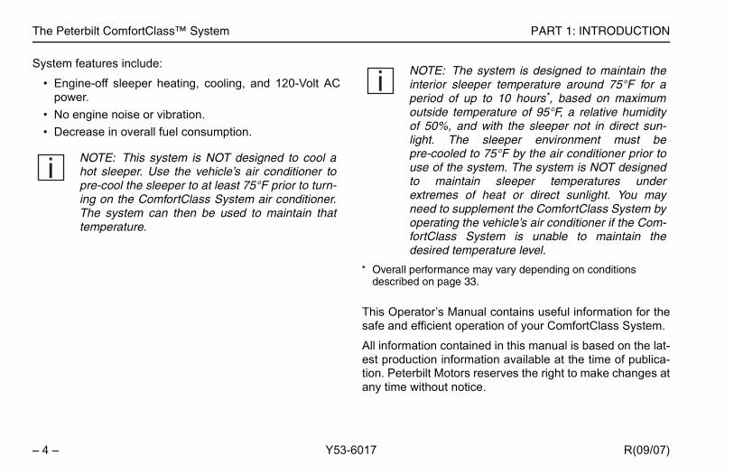
The system is designed to maintain the sleeper temperature around 75°F for aof up to 10 hours*, based on maximum temperature of 95°F, a relative humidity, and with the sleeper not in direct sun-The sleeper environment must beled to 75°F by the air conditioner prior to
the system. The system is NOT designedaintain sleeper temperatures underes of heat or direct sunlight. You may supplement the ComfortClass System byng the vehicle’s air conditioner if the Com-ss System is unable to maintain the temperature level.
ance may vary depending on conditions age 33.
Comfort_Class_System_OM.book Page 4 Thursday, November 1, 2007 1:12 PM
– Y53-6017
tem features include:
Engine-off sleeper heating, cooling, and 120-Volt ACpower.No engine noise or vibration.Decrease in overall fuel consumption.
Figure -13
This Operator’ssafe and efficien
All information cest production ition. Peterbilt Many time withou
NOTE: This system is NOT designed to cool ahot sleeper. Use the vehicle’s air conditioner topre-cool the sleeper to at least 75°F prior to turn-ing on the ComfortClass System air conditioner.The system can then be used to maintain thattemperature.
i NOTE:interiorperiod outsideof 50%light. pre-coouse of to mextremneed tooperatifortCladesired
* Overall performdescribed on p
The Peterbilt ComfortClass™ System
– 5 –
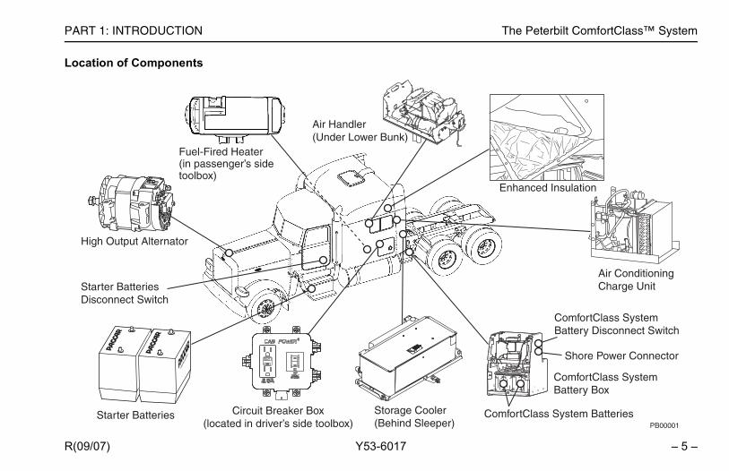
ComfortClass System Batteries)
ComfortClass System Battery Box
ComfortClass System Battery Disconnect Switch
Air ConditioningCharge Unit
Shore Power Connector
Enhanced Insulation
PB00001
Comfort_Class_System_OM.book Page 5 Thursday, November 1, 2007 1:12 PM
PART 1: INTRODUCTION
R(09/07) Y53-6017
Location of ComponentsFigure 1
Figure 2
Starter Batteries
High Output Alternator
Starter BatteriesDisconnect Switch
Storage Cooler(Behind Sleeper
Circuit Breaker Box(located in driver’s side toolbox)
Air Handler(Under Lower Bunk)
Fuel-Fired Heater(in passenger’s sidetoolbox)

The Peterbilt ComfortClass™ System PART 1: INTRODUCTION
– 6 R(09/07)
LocFigure 3
Figure -14
lation Air
Charge/Enable Switch(located on cab dash)(Page 37)
PB00002
CHARGE
Comfort_Class_System_OM.book Page 6 Thursday, November 1, 2007 1:12 PM
– Y53-6017
ation of Components
NORMAL
OFF/RESET
OFF
Inverter/Charger Lamp(Page 19)
Shore Power Lamp (120-Volt AC)(Page 19)
Air Conditioning/HeatingSwitch(Pages 29 & 32)
Inverter/Charger Switch(Page 18)
Air Conditioner Pump ON Lamp (Green)(Page 26)
Fan Control Dial (Page 26)
Sleeper Fresh/RecircuSwitch(Page 27)
Temperature Control Dial(Pages 29 & 32)
Sleeper Control Panel(located in Sleeper)

Charging/Jump-Starting Instructions
– 7 –
R SYSTEM
equipped with the ComfortClass System haveonfigurations that are different from traditionalThese vehicles have a dedicated set of batteriesn to the Starter Batteries. These batteries are as the “ComfortClass System Batteries.” These
provide power to the vehicles’ electrical demandson-board computers and the starting batteries.er is the only electrical device that does notn the ComfortClass System Batteries. The sche-age 9 is provided to help illustrate the system.
tarter BatteriesComfortClass SystemBatteries
PB00006A
Comfort_Class_System_OM.book Page 7 Thursday, November 1, 2007 1:12 PM
PART 2: ELECTRIC POWER SYSTEM
R(09/07) Y53-6017
Figure -15
PART 2: ELECTRIC POWE
Charging/Jump-Starting Instructions Figure -16
Figure -18
Figure -19
Figure -20
Vehicles battery cvehicles. in additioreferred tobatteries including The startdepend omatic on p
Figure -17
WARNING! The electrical charging systemused for the ComfortClass System is differentfrom normal charging systems. Failure toadhere to the proper charging or jump-startingprocedures could lead to death or seriousinjury, damage to the Inverter/Charger or vehi-cle damage. Follow the Charging/Jump-Start-ing Instructions on page 10.
i NOTE: The charging/jump-starting instructionscan also be found on the top of the ComfortClassSystem Battery Box cover.
S

Charging/Jump-Starting Instructions PART 2: ELECTRIC POWER SYSTEM
– 8 R(09/07)
Figure -21
i
Comfort_Class_System_OM.book Page 8 Thursday, November 1, 2007 1:12 PM
– Y53-6017
NOTE: Do not attempt to jump-start the vehiclewithout first reading the instructions on top of theComfortClass System Battery Box cover. If youhave a battery problem, it is best to contact anauthorized repair facility or a reputable towingservice. When you do, inform them of the charg-ing instructions on page 10 and the wiring sche-matic on page 9. These instructions can also befound on the top of the ComfortClass SystemBattery Box cover.

Charging/Jump-Starting Instructions
– 9 –
Comfort_Class_System_OM.book Page 9 Thursday, November 1, 2007 1:12 PM
PART 2: ELECTRIC POWER SYSTEM
R(09/07) Y53-6017
Figure 4
Wiring SchematicFigure 5

Charging/Jump-Starting Instructions PART 2: ELECTRIC POWER SYSTEM
– 1 R(09/07)
TheComtheveh Figure -22
Figure -23
Figure -24
-Starting Instructions
ccasions where the vehicle will crank but itven after charging the starting batteries
ng to jump-start the vehicle using normald in the Operator’s Manual. You may alsovoltage meter on your dash is below 11hts are dimmed or not on, and the DC out-er.
ns, the ComfortClass System System Bat- dropped below 9.5 volts. It is necessary tomfortClass System System Batteries toand ensure that the Starter Batteries are atr to start the vehicle.
i
i
i
The voltmeter only monitors the Comfort-ystem Batteries, not the Starter Batteries.
Comfort_Class_System_OM.book Page 10 Thursday, November 1, 2007 1:12 PM
0 – Y53-6017
ComfortClass System Batteries are located in thefortClass System Battery Box behind the sleeper, on
driver’s side. They power all electrical systems on theicle EXCEPT the starter motor.
Charging/Jump
There may be owill not start, eand/or attemptiprocedures founnotice that the volts, interior liglets have no pow Figure -25
In such situatiotery voltage hascharge the Coabove 11 volts (12 volts) in orde
NOTE: Because the ComfortClass System Bat-teries power the engine controls and starterrelay, you may experience a no-crank condition ifthe ComfortClass System Battery voltage isbelow 9.5-Volt, even though the Starter Batteriesare fully charged.
NOTE: A DC/DC charger, also located belowthe cab on the driver’s side, serves to isolate thestarting batteries from the ComfortClass SystemBatteries and provides charge to the starting bat-teries to maintain them at a minimum of 12-Volt.
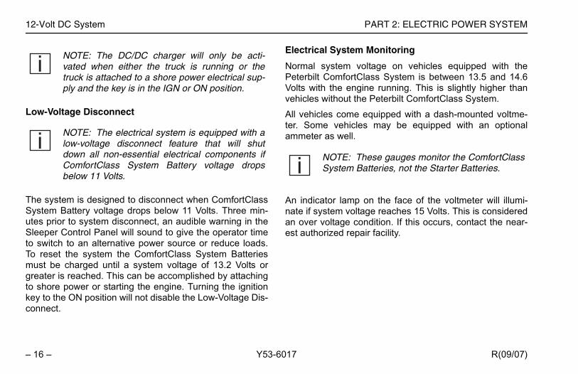
NOTE: The DC/DC charger will only be acti-vated when either the truck is running or thetruck is attached to a shore power electrical sup-ply and the key is in the IGN or ON position.
i NOTE:Class S

Charging/Jump-Starting Instructions
– 11 –
“Battery Charging” and “Jump-Starting Vehi-he Peterbilt Operator’s Manual for additional bat-ing and jump-starting procedures. Also, refer tobleshooting Section on page 41 for more
AUTION: Do not connect any accessoriesirectly to the starting batteries. This couldrain the batteries to a point where they can nonger start the engine.
Comfort_Class_System_OM.book Page 11 Thursday, November 1, 2007 1:12 PM
PART 2: ELECTRIC POWER SYSTEM
R(09/07) Y53-6017
Figure -26
Figure -27
The ComfortClass System Batteries are located in thedriver’s side frame-mounted box located behind thesleeper. The batteries can be accessed by removing thecover plate and connecting a charger to the charging termi-nals. Turn the battery disconnect switch, on the side of theComfortClass System Battery Box, to the “ON” position ifyou want to charge the batteries using the charging termi-nals. Charging these batteries can also be performed byusing the shore power connection on the side of this box.
Please have your ComfortClass System inspected by anauthorized dealer if your ComfortClass System Batteriescontinue to drop below 11 volts or if you are unable to startthe vehicle after charging both the starter and the Comfort-Class System Batteries.
Refer to cles” in ttery chargthe Troudetails. Figure -28
Charging Terminals
Shore PowerConnector
PB00032
Figure -29
Cddlo

Charging/Jump-Starting Instructions PART 2: ELECTRIC POWER SYSTEM
– 1 R(09/07)
Dis Figure -30
Figure -31
Priotem
1
2
3
mfortClass System Battery disconnecton ComfortClass System Battery Boxn driver’s side, rear of sleeper) to OFF
fortClass System Batteries using Shore
NG! Electric Shock Hazard. 120-Volt ACresent. This can cause electrical shockresulting in death, personal injury ory damage. Only a trained technician work on the shore power system. Turntery disconnect switches to the OFFn and unplug the shore power electricalbefore servicing any part of the vehi-
ectrical system.
ComfortClass SystemBatteries DisconnectSwitch
Shore PowerConnector
PB00005
Comfort_Class_System_OM.book Page 12 Thursday, November 1, 2007 1:12 PM
2 – Y53-6017
connect Instructions
r to servicing the vehicle, disconnect the electrical sys- as follows:
. Turn air heater off and wait three minutes prior toturning the disconnect switches to the OFF position(steps 3 and 4 below). This gives three minutes forthe heater to purge any fuel still in the heater andallows the unit to cool off.
. Unplug shore power connection.
. Turn Starter Battery disconnect to OFF position.
4. Turn Colocated (located oposition.
Charging ComPower Figure -32
Figure -33
Figure -34
ComfortClass SystemBatteries DisconnectSwitch (shown in theoff position)
ComfortClass SystemBattery Box
Shore PowerConnector
PB00004
Figure -35
WARNIpower por fire propertshouldall batpositiosupply cle’s el

Charging/Jump-Starting Instructions
– 13 –
ch the shore power cord to a 20 Amp protecteduit and the shore power connector until systemage is restored (9.5 Volts minimum at Comfort-ss System Batteries and 12 Volts minimum atrter Batteries). The shore power connector isted on the rear of the ComfortClass System Bat- Box.
ke sure the Inverter/Charger Switch (shown one 20) is in the ON position and that the circuitaker on the Protection Unit box has not beenped. The Shore Power Lamp on the Sleeper Con- Panel will illuminate green and therter/Charger Lamp will illuminate orange.
ystem voltage is 13.5 to 14.6 Volts with thenning. Typically the ComfortClass System Batter-reach at least a 9.5-Volt charge to power thentrols necessary to start the engine.
Comfort_Class_System_OM.book Page 13 Thursday, November 1, 2007 1:12 PM
PART 2: ELECTRIC POWER SYSTEM
R(09/07) Y53-6017
Figure -36
Figure -38
1. AttacircvoltClaStalocatery
2. MapagbretriptrolInve
Normal sengine ruies must engine co
Figure -37
WARNING! Electric Shock Hazard. 120-Volt ACpower present. An improperly maintainedshore power electrical system can cause firesand electrical shocks that may lead to death,personal injury or property damage. Regularlyinspect the shore power truck wiring, AC shorepower cord, plugs and connectors for dam-aged or frayed wiring. Do not use the shorepower system if there are any signs of prob-lems.
Figure -39
WARNING! Do not use an undersized ACextension cord or a cord that is too long asthere is an Electric Shock Hazard due to the120-Volt AC power present. An undersized ACextension cord can cause fires and electricalshocks that may lead to death, personal injuryor property damage. Always use a properlygrounded 20 Amp UL rated AC extension cordthat is no longer than 25 ft. and a 20 Amp ACprotected power source with a grounding con-ductor when connecting to a shore power elec-trical supply.
12-Volt DC System PART 2: ELECTRIC POWER SYSTEM
– 1 R(09/07)
12 Figure -40
Figure -41
ThefortageMoClasysteriBat
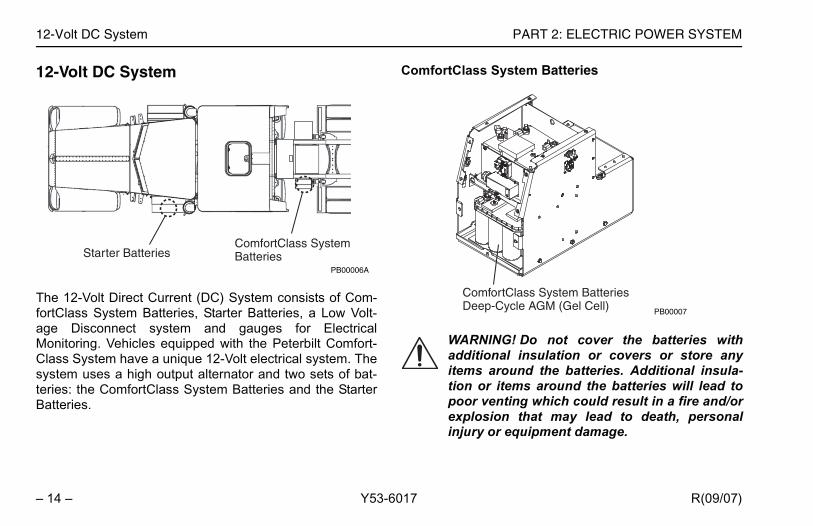
System Batteries
NG! Do not cover the batteries withnal insulation or covers or store anyround the batteries. Additional insula-items around the batteries will lead tonting which could result in a fire and/oron that may lead to death, personalr equipment damage.
ortClass System Batteries-Cycle AGM (Gel Cell) PB00007
Comfort_Class_System_OM.book Page 14 Thursday, November 1, 2007 1:12 PM
4 – Y53-6017
-Volt DC System
12-Volt Direct Current (DC) System consists of Com-Class System Batteries, Starter Batteries, a Low Volt- Disconnect system and gauges for Electrical
nitoring. Vehicles equipped with the Peterbilt Comfort-ss System have a unique 12-Volt electrical system. Thetem uses a high output alternator and two sets of bat-es: the ComfortClass System Batteries and the Starterteries.
ComfortClass Figure -42
Figure -43
Figure -44
Starter BatteriesComfortClass SystemBatteries
PB00006A
Figure -45
WARNIadditioitems ation or poor veexplosiinjury o
ComfDeep

12-Volt DC System
– 15 –
atteries
ter Batteries (two 1000 Cold Cranking Amptteries) are located below the cab on the driver’s vehicle. These batteries are used only to power
r motor.
charger serves to isolate the starting batteriesComfortClass System Batteries and provides
the Starter Batteries to maintain them at a mini-2 Volts.
OTE: The charging instructions can also beound on the top of the ComfortClass Systemattery Box cover.
PB00008
Comfort_Class_System_OM.book Page 15 Thursday, November 1, 2007 1:12 PM
PART 2: ELECTRIC POWER SYSTEM
R(09/07) Y53-6017
The ComfortClass System Batteries are located in theComfortClass System Battery Box on the driver’s side ofthe vehicle behind the sleeper compartment. The fourDeep Cycle AGM (Gel Cell) batteries power all electricalsystem components on the vehicle EXCEPT the startermotor. Figure -46
Figure -48
Starter B Figure -49
Figure -50
Figure -51
The Star12-Volt baside of thethe starte
A DC/DCfrom the charge tomum of 1
Figure -47
CAUTION: Do not replace the Deep Cycle AGM(Gel Cell) batteries with common lead acid bat-teries. The ComfortClass System is designedto draw to very low voltages which will signifi-cantly reduce the life of a lead acid battery. Useonly PACCAR recommended ComfortClassSystem Batteries. See your Peterbilt dealer foradditional information.
i NOTE: Because the ComfortClass System Bat-teries power the engine controls and starterrelay, you may experience a no-crank condition ifthe ComfortClass System Battery voltage isbelow 9.5-Volt, even though the Starter Batteriesare fully charged.
i NfB
12-Volt DC System PART 2: ELECTRIC POWER SYSTEM
– 1 R(09/07)
Figure -52
Low Figure -53
TheSysuteSleto sTo mugreto skeycon
em Monitoring
voltage on vehicles equipped with thertClass System is between 13.5 and 14.6ngine running. This is slightly higher than the Peterbilt ComfortClass System.
e equipped with a dash-mounted voltme-icles may be equipped with an optionalll.
p on the face of the voltmeter will illumi-oltage reaches 15 Volts. This is considered condition. If this occurs, contact the near-epair facility.
i
iThese gauges monitor the ComfortClass Batteries, not the Starter Batteries.
Comfort_Class_System_OM.book Page 16 Thursday, November 1, 2007 1:12 PM
6 – Y53-6017
-Voltage Disconnect
system is designed to disconnect when ComfortClasstem Battery voltage drops below 11 Volts. Three min-s prior to system disconnect, an audible warning in theeper Control Panel will sound to give the operator timewitch to an alternative power source or reduce loads.reset the system the ComfortClass System Batteriesst be charged until a system voltage of 13.2 Volts orater is reached. This can be accomplished by attachinghore power or starting the engine. Turning the ignition to the ON position will not disable the Low-Voltage Dis-nect.
Electrical Syst
Normal systemPeterbilt ComfoVolts with the evehicles without
All vehicles comter. Some vehammeter as we Figure -54
An indicator lamnate if system van over voltageest authorized r
NOTE: The DC/DC charger will only be acti-vated when either the truck is running or thetruck is attached to a shore power electrical sup-ply and the key is in the IGN or ON position.
NOTE: The electrical system is equipped with alow-voltage disconnect feature that will shutdown all non-essential electrical components ifComfortClass System Battery voltage dropsbelow 11 Volts.
i NOTE:System

Shore Power
– 17 –
e power system is located in the ComfortClassattery Box and consists of a 120-Volt AC Electri-m connection, Inverter/Charger, Circuit Breaker120-Volt AC outlets in the sleeper.
wer and Inverter
Shore Power Hook Up
PB00006B
Comfort_Class_System_OM.book Page 17 Thursday, November 1, 2007 1:12 PM
PART 2: ELECTRIC POWER SYSTEM
R(09/07) Y53-6017
Shore Power Figure -55
Figure -56
Figure -57
The shorSystem Bcal SysteBox, and
Shore Po Figure -59
Figure -60
Figure -58
WARNING! Electric Shock Hazard. 120-Volt ACpower present. This can cause electrical shockor fire resulting in death, personal injury and/orproperty damage. Only a trained technicianshould work on the shore power system. Turnall battery disconnect switches to the OFFposition and unplug the shore power electricalsupply before servicing any part of the vehi-cle’s electrical system.
ComfortClass SystemBattery Box
Shore PowerConnector
PB00010

Shore Power PART 2: ELECTRIC POWER SYSTEM
– 1 R(09/07)
Figure -61
The120powsou120
er Switch
C system function is controlled by ther Switch located on the Sleeper Control
the switch is pressed (NORMAL position),rger is on and the green electrical outlet
witch will turn on. This is the normal operat-he Inverter/Charger.
m of the switch is pressed (OFF/RESETverter/Charger will be off and the greensymbol on the switch will turn off. Refer toarger Indicator Chart on page 20 forn.
Figure -62
PB00011
Comfort_Class_System_OM.book Page 18 Thursday, November 1, 2007 1:12 PM
8 – Y53-6017
Peterbilt ComfortClass System enables you to access-Volt AC power from two different sources. A shoreer connection allows access to an outside powerrce and an electrical inverter system can produce-Volt AC from the ComfortClass System Batteries.
Inverter/Charg Figure -63
Figure -64
The 120-Volt AInverter/ChargePanel.
When the top ofthe Inverter/Chasymbol on the sing position for t
When the bottoposition), the Inelectrical outlet the Inverter/ChReset informatio
WARNING! Electric Shock Hazard. 120-Volt ACpower present. An improperly maintainedShore Power electrical system can cause firesand electrical shocks that may lead to death,personal injury or property damage. Regularlyinspect the shore power truck wiring, AC shorepower cord, plugs and connectors for dam-aged or frayed wiring. Do not use the shorepower system if there are any signs of prob-lems. Always use a properly grounded 20 AmpUL rated AC extension cord that is no longerthan 25 ft. and a 20 Amp AC protected powersource with a grounding conductor when con-necting to a shore power electrical supply.

Shore Power
– 19 –
Comfort_Class_System_OM.book Page 19 Thursday, November 1, 2007 1:12 PM
PART 2: ELECTRIC POWER SYSTEM
R(09/07) Y53-6017
Inverter/Charger & Shore Power Lamps Figure -65
Figure -66
The Inverter/Charger and Shore Power Lamps located inthe center of the Sleeper Control Panel will illuminate in anarray of colors and configurations to designate system sta-tus. Refer to the Inverter/Charger Indicator chart on thenext page for more information.
Inverter/Charger Lamp
Shore Power Lamp
PB00011A

Shore Power PART 2: ELECTRIC POWER SYSTEM
– 2 R(09/07)
InvFigure 6
Figure 7
System Status
Inverter Charger
ON OFF
Input Low Voltage OFF
put Low Voltage Warning OFF
ut Over Voltage Protection OFF
Overload; Short Circuit ection; Output Over Voltage
ProtectionOFF
Over Temp OFF
OFF ON
OFF Thermally Derated ChargeOFF Overload;
Short Circuit Protection
OFF Low Voltage Timed Charge
OFF Low Voltage Auto-Stop
Battery Disconnect
OFF
Comfort_Class_System_OM.book Page 20 Thursday, November 1, 2007 1:12 PM
0 – Y53-6017
erter/Charger Indicator Chart
Inverter/Charger & Shore Power Lamps Status
Inverter/Charger Lamp Shore Power LampInverter/Charge
SwitchShorePower
Solid Green OFF ON OFF
Blinking Green (0.5 sec ON, 0.5 sec OFF) OFF ON OFF
Blinking Green 3x (0.2 sec ON/OFF) 4.5 sec OFF OFF ON OFF In
Blinking Green (0.5 sec ON, 0.5 sec OFF) OFF ON OFF Inp
Solid Red OFF ON OFF Prot
OFF OFF ON OFF
Solid Orange Solid Green ON ON
Solid Orange Solid Green ON ONSolid Orange Solid Green ON ON
Blinking Orange/Red (4 sec Orange, 1 sec Red) Solid Green ON ON
Blinking Orange/Red (0.5 sec Orange, 0.5 sec Red) Solid Green ON ON
OFF OFF ON
OFF OFF OFF

Shore Power
– 21 –
Remedy
ation, no action required.
start if voltage reaches an acceptable level.ff switch to off/reset and then back on to reset inverter.1
start if voltage reaches an acceptable level.
ff switch to off/reset and then back on to reset inverter.1
tart if voltage reaches an acceptable level.ff switch to off/reset and then back on to reset inverter.1
ff switch to off/reset and then back on to reset inverter.1
start if temperature reaches an acceptable level.f switch to off/reset and then back on to reset inverter. 1
ation, no action required.emperatures, no action required.
start if conditions reach an acceptable level.ff switch to off/reset and then back on to reset inverter.1
ion, allows for charging of batteries as low as 5V, no action
re not successfully accepting a charge, inverter/charger will turn n/off switch to off/reset and then back on to reset
witch to off/reset. Reconnect batteries to inverter/charger. Turn to on.
, turn inverter/charger on/off switch to on.
aler.sful after restarting inverter/charger, replace main batteries.
Comfort_Class_System_OM.book Page 21 Thursday, November 1, 2007 1:12 PM
PART 2: ELECTRIC POWER SYSTEM
R(09/07) Y53-6017
Figure 8
Figure 9
Inverter/Charger & Shore Power Lamps Status
Inverter/Charger Lamp Shore Power Lamp
Solid Green OFF Normal inverter/charger oper
Blinking Green (0.5 sec ON, 4.5 sec OFF) OFF
- Inverter/charger will auto-re- Cycle inverter/charger on/o
Blinking GreenOFF
- Inverter/charger will auto-re
3x (0.2 sec ON/OFF) 4.5 sec OFF - Cycle inverter/charger on/o
Blinking Green (0.5 sec ON, 0.5 sec OFF) OFF
- Inverter/charger will auto-res- Cycle inverter/charger on/o
Solid Red OFF - Cycle inverter/charger on/o
OFF OFF - Inverter/charger will auto-re- Cycle inverter/charger on/of
Solid Orange Solid Green Normal inverter/charger oper
Solid Orange Solid Green Charging will derate at high t
Solid Orange Solid Green- Inverter/charger will auto-re- Cycle inverter/charger on/o
Blinking Orange/Red (4 sec Orange, 1 sec Red) Solid Green
Low voltage charging operatrequired.
Blinking Orange/Red (0.5 sec Orange, 0.5 sec Red) Solid Green
If batteries at a low voltage aoff. Cycle inverter/charger oinverter/charger.1,2
OFF OFFTurn inverter/charger on/off sinverter/charger on/off switch
OFF OFF For inverter/charger function1 If after restarting the inverter/charger the blink code persists, please see your local Peterbilt service de2 Continuous charging of low voltage batteries is not recommended. If low voltage charging is unsucces
Shore Power PART 2: ELECTRIC POWER SYSTEM
– 2 R(09/07)
Cir Figure -67
Figure -68
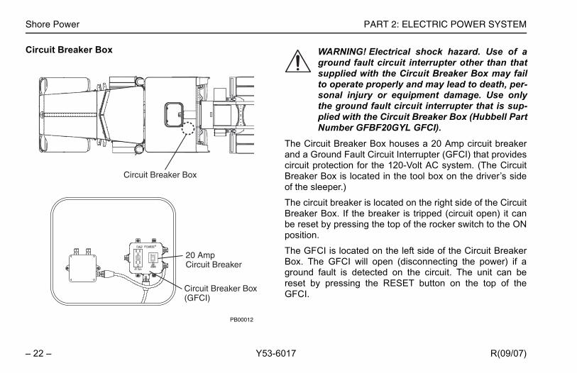
ker Box houses a 20 Amp circuit breakerault Circuit Interrupter (GFCI) that providesn for the 120-Volt AC system. (The Circuitlocated in the tool box on the driver’s side
ker is located on the right side of the Circuitthe breaker is tripped (circuit open) it cansing the top of the rocker switch to the ON
ated on the left side of the Circuit Breaker will open (disconnecting the power) if adetected on the circuit. The unit can beng the RESET button on the top of the
NG! Electrical shock hazard. Use of a fault circuit interrupter other than thatd with the Circuit Breaker Box may failate properly and may lead to death, per-njury or equipment damage. Use onlyund fault circuit interrupter that is sup-ith the Circuit Breaker Box (Hubbell Partr GFBF20GYL GFCI).
Comfort_Class_System_OM.book Page 22 Thursday, November 1, 2007 1:12 PM
2 – Y53-6017
cuit Breaker Box Figure -69
The Circuit Breaand a Ground Fcircuit protectioBreaker Box is of the sleeper.)
The circuit breaBreaker Box. If be reset by presposition.
The GFCI is locBox. The GFCIground fault is reset by pressiGFCI.
20 AmpCircuit Breaker
Circuit Breaker Box(GFCI)
Circuit Breaker Box
PB00012
Figure -70
WARNIgroundsupplieto opersonal ithe groplied wNumbe

Shore Power
– 23 –
OTE: The Inverter has its own low-voltage dis-onnect system that will shut off power to the twouplex outlets when the ComfortClass Systemattery voltage gets below 11 Volts.
Comfort_Class_System_OM.book Page 23 Thursday, November 1, 2007 1:12 PM
PART 2: ELECTRIC POWER SYSTEM
R(09/07) Y53-6017
Figure -71
120-Volt AC Outlets Figure -72
Figure -73
Two 120-Volt AC duplex style outlets are located in thesleeper compartment, one under the driver’s side lowerbunk, the second in the passenger side closet. They arepowered by either a shore power electrical supply or by theComfortClass System Batteries through the Inverter.
Figure -74
i NOTE: Replace GFCI if light on GFCI flashes. Ifthis is not done, outlets will not be powered.Replace with a new Hubbell GFBF20GYL GFCI.
120-Volt AC OutletsPB00013B
i NcdB

Shore Power PART 2: ELECTRIC POWER SYSTEM
– 2 R(09/07)
Comfort_Class_System_OM.book Page 24 Thursday, November 1, 2007 1:12 PM
4 – Y53-6017
NOTES

Controls and Switches
– 25 –
ITIONING SYSTEM
erature Control Dial is located on the left side ofer Control Panel. Turning the dial clockwise from’clock position to the red bands controls theeater. Turning the dial counterclockwise from the position to the blue bands controls the sleeperoning.
Heating ModeRed Bands
Conditioning Mode Bands
nditioning ON(Green)
PB00015
Comfort_Class_System_OM.book Page 25 Thursday, November 1, 2007 1:12 PM
PART 3: HEATING AND AIR CONDITIONING SYSTEM
R(09/07) Y53-6017
Figure -75
PART 3: HEATING AND AIR COND
Controls and Switches Figure -76
Figure -77
The Air Conditioning/Heating Switch is the leftmost switchin the Sleeper Control Panel. The middle is the OFF posi-tion of the switch. Pressing on the top of the switch will turnthe sleeper air conditioning system on. Pressing on thebottom of the switch will turn the sleeper fuel fired heateron.
Figure -78
Figure -79
The Tempthe Sleepthe 12 osleeper h12 o’clockair conditi
PB00014
Air Conditioning ON Position
Heat ON Position
OFF
Air Blue
Air CoPumpLamp

Controls and Switches PART 3: HEATING AND AIR CONDITIONING SYSTEM
– 2 R(09/07)
Figure -80
Figure -81
Thesidebangretempumcycper
Fan Control Dial
The more the pump is on, the more thehe Storage Cooler melts. When all of thes melted, you will lose the ability for the to provide cold air until the Storage has been recharged. See Storage on page 35.
OFF
l Dial
PB00021
Comfort_Class_System_OM.book Page 26 Thursday, November 1, 2007 1:12 PM
6 – Y53-6017
Air Conditioning Pump ON Lamp
Air Conditioning Pump ON Lamp is located on the left of the Temperature Control Dial between the blued and the white snowflake. The lamp will illuminateen when the Temperature Control Dial is turned to aperature range which requires the air conditioningp to turn on (i.e., colder temperature). The pump will
le on and off automatically to maintain a desired tem-ature.
Figure -82
Figure -83
Figure -84
Air Conditioning Pump ONLamp (Green)
PB00022
i NOTE:ice in tice hasystemCoolerCooler
Fan Contro

Controls and Switches
– 27 –
OTE: The Fresh/Recirculation Switch is onlyperational when the Fan Control Dial is in theN position. When the Fan Control Dial is in theFF position, the Fresh/Recirculation door and
ontrol will be deactivated. The Fresh/Recircula-ion door will remain in the position (open orlosed) selected prior to turning the fan off.
Comfort_Class_System_OM.book Page 27 Thursday, November 1, 2007 1:12 PM
PART 3: HEATING AND AIR CONDITIONING SYSTEM
R(09/07) Y53-6017
Fresh/Recirculation Air Switch Figure -85
Figure -86
The Fresh/Recirculation Air Switch is the rightmost switchon the Sleeper Control Panel. The two-position switch con-trols the source of the incoming air to the air conditioningand ventilation system. With the switch in the FRESH posi-tion (top position pressed), outside air is introduced to theair conditioning or ventilation system. In the RECIRCULA-TION position (bottom position pressed), sleeper air isrecirculated through the system.
The system can be operated in a ventilation only mode byplacing the Air Conditioning/Heating Switch in the OFFposition and moving the Fan Control Dial from the OFFposition. With the Fresh/Recirculation Switch in theFRESH position, outside air is vented to the sleeper com-partment.
Figure -87
PB00023
i NoOOctc
Using the Heater PART 3: HEATING AND AIR CONDITIONING SYSTEM
– 2 R(09/07)
Us Figure -88
Figure -90
Figure -89
Figure -91
NG! Exhaust fumes from the heatingntain carbon monoxide, a colorless ands gas. Do not breathe the heatert gas. A poorly maintained, damaged, ord exhaust system can allow carbon
ide to enter the cab or sleeper. Entry of monoxide into the cab or sleeper isssible from other vehicles nearby. Fail-properly maintain your vehicle couldcarbon monoxide to enter the
eper and cause serious illness that maydeath.
When filling fuel tanks with low-tempera-l, run the air heater for 15 minutes in
climates to circulate the low-temperature the heater system to prevent the fuel fromn colder climates.
Comfort_Class_System_OM.book Page 28 Thursday, November 1, 2007 1:12 PM
8 – Y53-6017
ing the Heater Figure -92
Figure -94
WARNING! Do not operate the sleeper heatingsystem or ventilating system around hazard-ous fumes or exhaust gases. Hazardous fumesand exhaust fumes may be vented into thesleeper compartment causing serious illnessthat may lead to death. Do not park your vehi-cle near other vehicles that are idling or whereother hazardous fumes may be present.
WARNING! Do not operate the heater portion ofthe ComfortClass System when vehicle is in anenclosed, unventilated area. Exhaust fumesfrom the air heater contain carbon monoxide, acolorless and odorless gas which, if inhaled,can cause serious illness that may lead todeath. Never park in an enclosed area whenoperating the heater.
Figure -93
WARNIunit coodorlesexhauscorrodemonoxcarbonalso poure to cause cab/slelead to
i NOTE:ture fuewarmerfuel intogelling i

Using the Heater
– 29 –
Temperature Control Dial
urn the Temperature Control Dial clockwise to theode. Turning the dial in a clockwise direction
on dial) increases both the temperature and the Heater fan speed simultaneously. Turn the knob to increase the temperature or counterclockwisese the temperature. Once the desired tempera-ached, the system will maintain it automatically. not calibrated to specific temperatures.
Heating ModeRed Bands
PB00017
Comfort_Class_System_OM.book Page 29 Thursday, November 1, 2007 1:12 PM
PART 3: HEATING AND AIR CONDITIONING SYSTEM
R(09/07) Y53-6017
Follow the steps to properly start and operate the heater. Figure -95
Air Conditioning/Heating Switch Figure -96
Step 1: Turn the Air Conditioning/Heating Switch to theHeater ON position. Figure -97
Figure -98
Figure -99
Step 2: THeating M(red bandFuel-Firedclockwiseto decreature is reThe dial is
i NOTE: A flashing RED lamp indicates a systemfault. Contact the nearest authorized repair facil-ity.
PB00016
Heat ON Position

Using the Heater PART 3: HEATING AND AIR CONDITIONING SYSTEM
– 3 R(09/07)
StetheTIOFan
ter
Heater is a stand-alone unit that is con-the Sleeper Control Panel. It is located inlbox on the side of the vehicle. Its designe similar to units used on other vehicles.s diesel fuel drawn from the vehicle’s fuel heat.
PB00018
Fuel-Fired Heater
Comfort_Class_System_OM.book Page 30 Thursday, November 1, 2007 1:12 PM
0 – Y53-6017
p 3: If you want more air from the vents, you can set Fresh/Recirculation Air Switch to the RECIRCULA-N position and increase the air from the vents via the Control Dial.
Fuel-Fired Hea Figure -100
Figure -101
The Fuel-Fired trolled only by front of the tooand function arThe heater usetank(s) to create

PART 3: HEATING AN ing the Air Conditioner
R(09/07)
Using the Air Co Figure -102
Figure -104
Figure -106
Figure -103
WARNING! Dditioning syshazardous fufumes and ethe sleeper ness that mavehicle nearwhere other
Figure -105
WARNING! Dgas. Exhauscarbon mongas. A poorroded exhauoxide to entserious illnesthe exhaust 7,500 miles (
i NOTE: This ssleeper. Usepre-cool the son the Comfosystem can thture.
igned to maintain there around 75°F for aased on maximum out-a relative humidity of not in direct sunlight.
ust be pre-cooled toprior to use of the sys-designed to maintainr extremes of heat ored to supplement theerating the vehicle’s airlass System is unableperature level.ding on conditions
D AIR CONDITIONING SYSTEM Us
nditioner Figure -107
o not operate the sleeper air con-tem or ventilating system aroundmes or exhaust gases. Hazardousxhaust fumes may be vented intocompartment causing serious ill-y lead to death. Do not park your other vehicles that are idling orhazardous fumes may be present.
o not breathe the engine exhaustt fumes from the engine containoxide, a colorless and odorlessly maintained, damaged, or cor-st system can allow carbon mon-er the cab or sleeper and causes that may lead to death. Inspect
system for leaks monthly or every
i NOTE: The system is desinterior sleeper temperatuperiod of up to 10 hours*, bside temperature of 95°F, 50%, and with the sleeperThe sleeper environment m75°F by the air conditioner tem. The system is NOT sleeper temperatures undedirect sunlight. You may neComfortClass System by opconditioner if the ComfortCto maintain the desired tem
* Overall performance may vary dependescribed on page 33.
Y53-6017 – 31 –
12,000 km).
ystem is NOT designed to cool a hot the vehicle’s air conditioner toleeper to at least 75°F prior to turningrtClass System air conditioner. Theen be used to maintain that tempera-

Using the Air Conditioner PART 3: HEATING AND AIR CONDITIONING SYSTEM
– 3 R(09/07)
Figure -108
Figure -109
Foltion
Stecon
Temperature Control Dial
Blue Band − Air Conditioning Mode Up toling
Reduceg Time
PB00020
Comfort_Class_System_OM.book Page 32 Thursday, November 1, 2007 1:12 PM
2 – Y53-6017
Air Conditioning/Heating Switch
low the steps to properly start and operate the air condi-er.
p 1: Turn the Air Conditioning/Heating Switch to the airditioning ON position.
Figure -110
Figure -111
PB00019
Air Conditioning ON Position
Green Band −10 Hours Coo
Yellow Band −Overall Coolin

Using the Air Conditioner
– 33 –
fficiency
maximize engine-off cooling many factors mustered. The following factors all affect the system’sility:
t Sunlightle Colorent Temperature Compartment Temperature Air Mixer Curtain Positionow Coverings
OTE: Setting the dial in the yellow band willower the output temperature produced by theystem. Leaving the dial in this position forxtended periods will cause the ice in the Stor-ge Cooler to melt more quickly, thus reducing
he amount of cooling time available for your use.hen all of the ice has melted, you will lose the
bility for the system to provide cold air until thetorage Cooler has been recharged. See Stor-ge Cooler on page 35.
Comfort_Class_System_OM.book Page 33 Thursday, November 1, 2007 1:12 PM
PART 3: HEATING AND AIR CONDITIONING SYSTEM
R(09/07) Y53-6017
Step 2: Turn the Fan Control Dial clockwise to start thefan. Continuing to turn the dial clockwise will graduallyincrease fan speed. In the full counterclockwise positionthe dial is in the OFF position. In the OFF position, the airconditioning system will be deactivated. The dial controlsfan speed for the air conditioning system only and not forthe heater.
Step 3: Turn the Temperature Control Dial counterclock-wise to the Air Conditioning Mode. Continuing to turn thedial in a counterclockwise direction (blue band on dial) willlower (colder) the air conditioning output temperature.Once the desired temperature is reached, the system willmaintain it automatically. Setting the dial within the greenband should give up to 10 hours of cooling (dependingupon the outside heat conditions). Adjusting the dial furtherto the left (yellow band on dial) will lower the output tem-perature. The dial is not calibrated to specific tempera-tures, so where you position the dial to achieve the sametemperature will vary depending on the current outsidetemperature conditions.
Figure -112
Cooling E
In order tobe considcooling ab
• Direc• Vehic• Ambi• Initial• Intake• Sleep• Wind
i NlseatWaSa

Using the Air Conditioner PART 3: HEATING AND AIR CONDITIONING SYSTEM
– 3 R(09/07)
Figure -113
Figure -114
oling ability:
compartment should already be at a max-mperature using the cab A/C system.covers and sleeper curtain should be insed.ecirculation Air Switch should be in theTION position.ture Control Dial of the sleeper should be
band.d pollen filter must be clean and clear ofen.st be parked in shade out of direct sun-
i
i
* Od
Comfort_Class_System_OM.book Page 34 Thursday, November 1, 2007 1:12 PM
4 – Y53-6017
For maximum co
• The sleeper imum 75°F te
• The window place and clo
• The Fresh/RRECIRCULA
• The Temperain the green
• The dust andust and poll
• The truck mulight.
NOTE: This system is NOT designed to cool ahot sleeper. Use the vehicle’s air conditioner topre-cool the sleeper to at least 75°F prior toturning on the ComfortClass System airconditioner. The system can then be used tomaintain that temperature.
NOTE: The system is designed to maintain theinterior sleeper temperature around 75°F for aperiod of up to 10 hours*, based on maximumoutside temperature of 95°F, a relative humidityof 50%, and with the sleeper not in directsunlight. The sleeper environment must bepre-cooled to 75°F by the air conditioner prior touse of the system. The system is NOT designedto maintain sleeper temperatures underextremes of heat or direct sunlight. You mayneed to supplement the ComfortClass System byoperating the vehicle’s air conditioner if theComfortClass System is unable to maintain thedesired temperature level.
verall performance may vary depending on conditions escribed on page 33.
Cooling System Components
– 35 –
ooler
Storage Coolernt Reservoir
Storage Cooler
PB00026
Comfort_Class_System_OM.book Page 35 Thursday, November 1, 2007 1:12 PM
PART 3: HEATING AND AIR CONDITIONING SYSTEM
R(09/07) Y53-6017
Cooling System ComponentsCooling Vents Figure -115
Figure -116
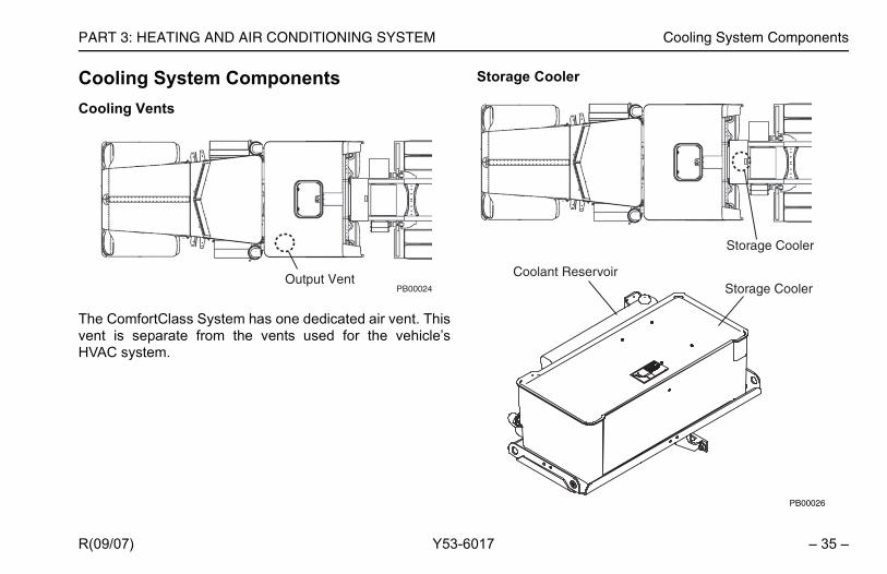
The ComfortClass System has one dedicated air vent. Thisvent is separate from the vents used for the vehicle’sHVAC system.
Storage C Figure -117
Figure -118
PB00024Output Vent Coola

Cooling System Components PART 3: HEATING AND AIR CONDITIONING SYSTEM
– 3 R(09/07)
Figure -119
Thethesysbe Cha(frohouappCoois 4 Figure -121
g Charge Unit
Figure -120
i
Air Conditioning Charge Unit
PB000028
Comfort_Class_System_OM.book Page 36 Thursday, November 1, 2007 1:12 PM
6 – Y53-6017
Storage Cooler is located behind the sleeper. It stores system’s cooling capacity by freezing water. As thetem is used, the ice melts back into water and needs torecharged (frozen) again by the Air Conditioningrge Unit in order to cool the sleeper. A fully charged
zen) Storage Cooler can cool the sleeper up to 10rs (depending on the outside heat conditions). Theroximate time required to fully charge the Storageler, without the ComfortClass air handler and pump on, to 6 hours.
Air Conditionin Figure -122
Figure -123
CAUTION: The coolant reservoir on the Stor-age Cooler does not require maintenance. Ifcoolant is added, use only a 50/50 mix of waterand antifreeze to prevent coolant from freezingin the Storage Cooler.
NOTE: The sleeper cooling system can be usedwhile the Storage Cooler is being charged by theAir Conditioning Charge Unit; however, this willincrease the time required to fully charge theStorage Cooler.

Cooling System Components
– 37 –
nable Switch
SPARE
SPARESPAREREAR
O
O
AC
AUX CHARGE
PB00033
Charge Enable Switch
Comfort_Class_System_OM.book Page 37 Thursday, November 1, 2007 1:12 PM
PART 3: HEATING AND AIR CONDITIONING SYSTEM
R(09/07) Y53-6017
The Air Conditioning Charge Unit is an electric refrigerationunit that operates automatically to cool the Storage Cooler,and is located on the passenger’s side of the vehicle,behind the sleeper compartment. The dash-mountedCharge/Enable Switch must be in the CHARGE position toenable the Charge Unit to operate. The unit will operatewhen the engine is running or connected to a shore powerelectrical supply. It will not operate using only batterypower as this will deplete the batteries too quickly. Figure -124
Figure -126
Charge/E Figure -128
Figure -129
Figure -125
WARNING! Electrical Shock Hazard. 120 VoltsAC are present inside the charging unit. Thiscan cause electrical shock or fire resulting indeath, personal injury and/or property damage.Disconnect shore power source to inverterbefore servicing equipment.
Figure -127
WARNING! Immediately get away from vehicleif you hear sounds or arcing (sizzling, sputter-ing or popping) inside the charging unit. Hotgas may vent from compressor terminals caus-ing death, personal injury and/or property dam-age. Improper servicing can lead to fire,electrocution or explosion which can result indeath, personal injury and/or property damage.Never service, repair or troubleshoot a systemunless you are a trained service person.

Cooling System Components PART 3: HEATING AND AIR CONDITIONING SYSTEM
– 3 R(09/07)
Theenarepbe SwwillConplalam Figure -130
Figure -131
i
i
The Charge/Enable Switch does not turn Sleeper Air Conditioning System. It onlys the Air Conditioning Charge Unit toe/replenish the Storage Cooler.
Comfort_Class_System_OM.book Page 38 Thursday, November 1, 2007 1:12 PM
8 – Y53-6017
Charge/Enable Switch is located on the cab dash andbles the Air Conditioning Charge Unit to refreeze/lenish the Storage Cooler. The switch should normallyleft in the CHARGE position (top of switch is pressed).itching to the OFF position (bottom of switch is pressed) disable the Air Conditioning Charge Unit. When the Airditioning Charge Unit is on, a green lamp will be dis-
yed on the Charge/Enable Switch. When the greenp turns off, the charging cycle is complete.
Figure -132
NOTE: Upon initial start-up of the truck engine,the ComfortClass System Batteries must gothrough a charge cycle before the Air Condition-ing Charge Unit will begin charging the StorageCooler. This ComfortClass System Batterycharge cycle can take up to 60 minutes. The airconditioning compressor will not turn on until thisComfortClass System Battery charge cycle iscompleted. Leave the Charge/Enable Switch inthe CHARGE position during the battery chargecycle.
NOTE: The green lamp can cycle on and off asthe system maintains the cooling capacity.
i NOTE:on theenablerefreez

Preventative Maintenance
– 39 –
d replace dirty dust and pollen filter once everys, or earlier if operating in highly dusty environ-
r
fortClass System utilizes a fuel-fired heater. Sub-, the heater has a dedicated fuel filter and is ale part.
and Pollen Filter
Air Handler PB00030
Comfort_Class_System_OM.book Page 39 Thursday, November 1, 2007 1:12 PM
PART 3: HEATING AND AIR CONDITIONING SYSTEM
R(09/07) Y53-6017
Preventative MaintenanceThe following section identifies serviceable parts for theComfortClass System. You may avoid expensive andtime-consuming repairs by replacing serviceable parts atthe recommended intervals. Your system will operate bet-ter, will operate safer and will last longer. Neglect of recom-mended maintenance may void your vehicle’s warranty.
Dust and Pollen Filter
The ComfortClass System air handler has a dust and pol-len filter. To access the air handler, raise the lower bunkfrom inside the sleeper.
Figure -133
Figure -134
Check an12 monthments.
Fuel Filte
The Comsequentlyserviceab
Dust

Preventative Maintenance PART 3: HEATING AND AIR CONDITIONING SYSTEM
– 4 R(09/07)
Figure -135
Figure -136
ThesidemoRep Figure -137
i
Comfort_Class_System_OM.book Page 40 Thursday, November 1, 2007 1:12 PM
0 – Y53-6017
fuel filter is located along the frame above the driver fuel tank. The fuel filter should be inspected every 12
nths. Check the filter for debris, sediment or water.lace if any is found.
NOTE: Do not substitute the Webasto suppliedfuel filter with a non-Webasto replacement filter.Irregular heater operation may result if anon-Webasto filter is used.
PB00031
Fuel FilterDriver SideFuel Tank

– 41 –
OTINGRemedy
h switch is in the ON position.r Switch is in the ON position.
in the Circuit Breaker Box is not tripped. Reset if necessary.rvice/refrigerant level check.rature is below 55°F, compressor will not turn on.)
position.de is selected.l is set in the blue zone.filter.
l is set in the green zone.gh curtain is closed and all window coverings are installed.
lected.l is set in the red zone.ink codes at the heater mode selection LED.compartment is not blocked.es are not blocked.
Comfort_Class_System_OM.book Page 41 Thursday, November 1, 2007 1:12 PM
PART 4: TROUBLESHOOTING
R(09/07) Y53-6017
Figure -138
PART 4: TROUBLESHO Figure -139
Concern Possible Cause
Parked truck will not get cool.
Storage Cooler not charged.
1. Make sure Charge/Enable das2. Make sure the Inverter/Charge3. Make sure the circuit breaker 4. Air conditioning component se
(Please note, if outside tempe
Lack of cool air out of vents.
1. Make sure blower is in the ON2. Make sure air conditioning mo3. Make sure temperature contro4. Service fresh air/recirculation 5. Check coolant level.6. Component service.7. Cab was not pre-cooled.
Parked truck will not stay cool for up to 10 hours.
Storage Cooler is depleting too quickly.
1. Make sure temperature contro2. Make sure sleeper pass-throu
Parked truck will not get warm.
Lack of hot air out of lower heater vent.
1. Make sure heating mode is se2. Make sure temperature contro3. Check for heater diagnostic bl4. Make sure heater inlet in tool 5. Make sure fuel and exhaust lin6. Component service.

PART 4: TROUBLESHOOTING
– 4 R(09/07)
Sleou
n ComfortClass System Battery Box is in the ON
in the ON position.ircuit Breaker Box is not tripped. Reset if necessary.r Box is not tripped. Reset if necessary.
CaDC
the ON position.et, ComfortClass System Battery voltage must be e truck or using Shore Power electrical supply).voltage. If voltage is below 11 Volts, charge the
Ca re in the ON position. ply to charge ComfortClass System Batteries or inals.
re in the ON position.e is below 12 Volts (check at starter using voltmeter), battery charger. discharge, replace starting batteries and/or have an hicle.
Remedy
Comfort_Class_System_OM.book Page 42 Thursday, November 1, 2007 1:12 PM
2 – Y53-6017
eper AC electrical tlets not working.
No power to sleeper AC electrical outlets.
1. Make sure battery disconnect switch oposition.
2. Make sure Inverter/Charger Switch is 3. Make sure the circuit breaker in the C4. Make sure GFCI in the Circuit Breake5. Component service.
nnot run cab/sleeper loads.
Not enough power available for cab/sleeper DC loads.
1. Make sure battery disconnects are in 2. Make sure LVD is not tripped. (To res
brought up to 13.2 Volts by starting th3. Check ComfortClass System Battery
ComfortClass System Batteries.
nnot start truck. Voltage at ComfortClass System Batteries is too low (below 9.5 Volts).
1. Make sure both battery disconnects a2. Hook up to Shore Power electrical sup
attach battery charger to charging term
Not enough cranking power from starting batteries.
1. Make sure both battery disconnects a2. Check starting battery voltage. If voltag
charge starting batteries with external3. If starting battery voltage continues to
authorized repair facility service the ve
Concern Possible Cause
Related Documents