Analysis of the combustion process, pollutant emissions and efficiency of an innovative 2-stroke HSDI engine designed for automotive applications Jesus Benajes a,1 , Ricardo Novella a, * ,1 , Daniela De Lima a,1 , Pascal Tribotté b, 2 , Nicolas Quechon b, 2 , Philippe Obernesser b, 2 , Vincent Dugue b, 2 a CMT-Motores Térmicos, Universitat Politècnica de València, Camino de Vera s/n, 46022 Valencia, Spain b Renault SAS Rue du Golf 1, 78288 Guyancourt, France highlights The paper describes in detail the air management in poppet valves 2-stroke engines. The best air management is obtained with high pressure drop but low valves overlap. The paper analyses the relation between combustion process and exhaust emissions. Air management is critical to attain competitive pollutants and thermal efficiency. Results confirm the potential to improve equivalent 4-stroke engine efficiencies. article info Article history: Received 24 November 2012 Accepted 28 March 2013 Available online 25 April 2013 Keywords: Diesel engine 2-Stroke engine Diffusion-controlled combustion Pollutant emissions Engine efficiency abstract On the last years engine researchers has been focused on improving engine efficiency in order to decrease CO 2 emissions and fuel consumption, while fulfilling the increasingly stringent pollutant emissions regulations. In this framework, engine downsizing arises as a promising solution, and 2-stroke cycle operation offers the possibility of reducing the number of cylinders without incurring in NVH penalties. An experimental investigation has been performed to evaluate the performance of a newly-designed poppet valves 2-stroke engine, in terms of finding the proper in-cylinder conditions to fulfill the emission limits in terms of NO x and soot, keeping competitive fuel consumption levels. Moreover, present research work aims to improve the existing knowledge about the gas exchange processes in a 2-stroke engine with poppet valves architecture, and its impact over the combustion conditions, final exhaust emissions levels and engine efficiency. The experimental results confirm how this engine architecture presents high flexibility in terms of air management control to substantially affect the in-cylinder conditions. The in-cylinder oxygen concen- tration and density, which are the product of a given trapping ratio and delivered mass flow, were linked to pollutant emissions and performance by their impact on instantaneous adiabatic flame temperature and spray mixing conditions. After the optimization process, it was possible to minimize simultaneously NO x , soot and indicated fuel consumption, without observing a critical trade-off between the pollutant emissions and the fuel consumption. Ó 2013 Elsevier Ltd. All rights reserved. 1. Introduction On the past years, development of HSDI diesel engines has been primarily driven by the reduction of exhaust emissions, imposed by increasingly stringent pollutant emissions regulations, especially in terms of NO x and soot emissions. Recently, research effort is being shifted toward the improvement of engine efficiency due to the * Corresponding author. Tel.: þ34 96 387 76 55; fax: þ34 96 387 76 59. E-mail address: [email protected] (R. Novella). 1 Tel.: þ34 96 387 76 50; fax: þ34 96 387 76 59. 2 Tel.: þ33 (0)1 76 85 69 04; fax: þ33 (0)1 76 85 77 16. Contents lists available at SciVerse ScienceDirect Applied Thermal Engineering journal homepage: www.elsevier.com/locate/apthermeng 1359-4311/$ e see front matter Ó 2013 Elsevier Ltd. All rights reserved. http://dx.doi.org/10.1016/j.applthermaleng.2013.03.050 Applied Thermal Engineering 58 (2013) 181e193

Welcome message from author
This document is posted to help you gain knowledge. Please leave a comment to let me know what you think about it! Share it to your friends and learn new things together.
Transcript
at SciVerse ScienceDirect
Applied Thermal Engineering 58 (2013) 181e193
Contents lists available
Applied Thermal Engineering
journal homepage: www.elsevier .com/locate/apthermeng
Analysis of the combustion process, pollutant emissions and efficiencyof an innovative 2-stroke HSDI engine designed for automotiveapplications
Jesus Benajes a,1, Ricardo Novella a,*,1, Daniela De Lima a,1, Pascal Tribotté b,2,Nicolas Quechon b,2, Philippe Obernesser b,2, Vincent Dugue b,2
aCMT-Motores Térmicos, Universitat Politècnica de València, Camino de Vera s/n, 46022 Valencia, SpainbRenault SAS Rue du Golf 1, 78288 Guyancourt, France
h i g h l i g h t s
� The paper describes in detail the air management in poppet valves 2-stroke engines.� The best air management is obtained with high pressure drop but low valves overlap.� The paper analyses the relation between combustion process and exhaust emissions.� Air management is critical to attain competitive pollutants and thermal efficiency.� Results confirm the potential to improve equivalent 4-stroke engine efficiencies.
a r t i c l e i n f o
Article history:Received 24 November 2012Accepted 28 March 2013Available online 25 April 2013
Keywords:Diesel engine2-Stroke engineDiffusion-controlled combustionPollutant emissionsEngine efficiency
* Corresponding author. Tel.: þ34 96 387 76 55; faE-mail address: [email protected] (R. Novella).
1 Tel.: þ34 96 387 76 50; fax: þ34 96 387 76 59.2 Tel.: þ33 (0)1 76 85 69 04; fax: þ33 (0)1 76 85 7
1359-4311/$ e see front matter � 2013 Elsevier Ltd.http://dx.doi.org/10.1016/j.applthermaleng.2013.03.05
a b s t r a c t
On the last years engine researchers has been focused on improving engine efficiency in order todecrease CO2 emissions and fuel consumption, while fulfilling the increasingly stringent pollutantemissions regulations. In this framework, engine downsizing arises as a promising solution, and 2-strokecycle operation offers the possibility of reducing the number of cylinders without incurring in NVHpenalties.
An experimental investigation has been performed to evaluate the performance of a newly-designedpoppet valves 2-stroke engine, in terms of finding the proper in-cylinder conditions to fulfill the emissionlimits in terms of NOx and soot, keeping competitive fuel consumption levels. Moreover, present researchwork aims to improve the existing knowledge about the gas exchange processes in a 2-stroke enginewith poppet valves architecture, and its impact over the combustion conditions, final exhaust emissionslevels and engine efficiency.
The experimental results confirm how this engine architecture presents high flexibility in terms of airmanagement control to substantially affect the in-cylinder conditions. The in-cylinder oxygen concen-tration and density, which are the product of a given trapping ratio and delivered mass flow, were linkedto pollutant emissions and performance by their impact on instantaneous adiabatic flame temperatureand spray mixing conditions. After the optimization process, it was possible to minimize simultaneouslyNOx, soot and indicated fuel consumption, without observing a critical trade-off between the pollutantemissions and the fuel consumption.
� 2013 Elsevier Ltd. All rights reserved.
x: þ34 96 387 76 59.
7 16.
All rights reserved.0
1. Introduction
On the past years, development of HSDI diesel engines has beenprimarily driven by the reduction of exhaust emissions, imposed byincreasingly stringent pollutant emissions regulations, especially interms of NOx and soot emissions. Recently, research effort is beingshifted toward the improvement of engine efficiency due to the

Table 1Main engine geometrical characteristics.
Displacement 365 cm3
Bore 76 mmStroke 80.5 mmConnecting rod length 133.75 mmGeometric CR 17.8Number of valves/cylinder 4Type of scavenge Poppet valves with scavenge loopIntake camshaft profile Duration: 80 cad/max. lift: 6 mmExhaust camshaft definition Duration: 95 cad/max. lift: 8.5 mm
J. Benajes et al. / Applied Thermal Engineering 58 (2013) 181e193182
need of decreasing CO2 emissions and also of meeting the expec-tations of costumers regarding fuel consumption.
In this frame, conventional mixing-controlled diesel combus-tion will continue to be an important source for both NOx andparticulate matter emissions (traced by soot emissions), and majorefforts in optimizing diesel engines are currently being focused ondecreasing simultaneously these two pollutant emissions withoutincreasing significantly their competitive fuel consumption. Previ-ous research works on advanced combustion concepts with highdegree of premixing and low oxygen concentration, such as HCCI[1], PCCI [2,3] and LTC [4] combustions, confirmed how it is possibleto decrease down to near to zero values NOx and soot levelssimultaneously [5]. Nevertheless, several technological drawbackshas not been yet solved, such as combustion noise [6], combustionphasing control [7,8] and high COeHC emissions, among others,compromising the real application of these strategies in smallpassenger cars, particularly using diesel fuel.
Among the different technical approaches investigated toreduce fuel consumption and CO2 emissions, a promising solutionconsists of downsizing the diesel engine by reducing the enginedisplacement [9,10], which requires a high specific power output tomaintain the expected performance and drivability [11,12]. How-ever, heavily downsizing of diesel engines still presents sometechnical challenges ahead; mainly in terms of turbocharging sys-tems [13], thermo mechanical resistance, high pressure/speed in-jection systems [14] and powertrain NVH [15,16].
An interesting alternative for extreme downsizing is takingadvantage of the 2-stroke engine cycle, which doubles the firingevents per crankshaft revolution, to reduce the number of cylinderswithout incurring in NVH penalties. Moreover, the need of morecompact engines with higher power-to-weight ratios for small/economic passenger cars or as a range extenders for hybrid appli-cations, recently revived the interest in investigating the 2-strokeoperation in diesel HSDI engines [17,18].
The idea behind this new engine concept is to depart from aconventional HSDI diesel 4-stroke engine (1460 cm3, 4 cylinders)and implement a 2-stroke operation cycle to downsize the enginedisplacement by a factor of two, obtaining a 2-stroke engine(730 cm3, 2 cylinders) with equivalent NVH and similar torqueresponse than the 4-stroke 4 cylinder engine. Cylinder-exhaust-ported engines and uniflow architectures were rejected for reli-ability and investment reasons, whereas the poppet valves archi-tecture with scavenging loop offered several advantages in termsof durability, design and manufacturing, so it was chosen for thisnew engine concept regardless of its scavenging and trappingdifficulties [17].
Then, the 2-stroke engine architecture investigated in thisresearch work performs the gas exchange process through poppetvalves placed on the cylinder head, and both intake and exhaustevents are shorter and more overlapped compared to the 4-strokecycle. Additionally, a positive pressure drop between the intake andexhaust ports, defined as DP, is mandatory over the complete rangeof engine speeds to allow the proper scavenging of the burnt gasesand minimize the rate of internal gas recirculation (burnt gaseswhich are not expelled out of the cylinder after the exhaust event).Advanced supercharging technology is required to achieve theexpected high DP ratios, as well as a variable valve timing systemfor controlling the camshafts phasing and overlap period betweenthe intake and exhaust phases. The first stages of conception,focused on the calculation and pre-design of the air loop systemand the combustion chamber geometry of this 2-stroke conceptengine, has been described in detail in two previous publications,along with some preliminary experimental results [17,18].
The control of the air management and in-cylinder conditionson this type of engine architecture is fundamental for both
combustion development and final engine cycle efficiency,increasing significantly the complexity of engine optimization andcalibration; mainly because there are multiple air managementactuation levers to be controlled aside from the usual injectionsettings. Therefore, it is important to establish a proper testingmethodology when optimizing the combustion/emissions charac-teristics of this 2-stroke engine architecture [19,20].
Departing from this background, this research has been focusedon the evaluation of this newly-designed 2-stroke engine conceptconsidering air management, combustion, pollutant emissions andperformance. Additionally, this research work aims to improve theunderstanding of the relation between the gas exchange processand the most important combustion-related parameters, whichwill determine the final exhaust emissions levels and engine fuelconsumption. Since the in-cylinder conditions are highly sensitiveto air management settings, a DOE optimization methodology hasbeen proposed to establish the real potential of this engine archi-tecture in terms of emissions and fuel consumption; keeping in thisfirst stage of engine evaluation the emissions limits demanded bythe EU5 legislation to gain the knowledge required for developingfuture strategies to switch toward future EU6 emission levels.
2. Experimental setup
2.1. Engine architecture and hardware
The experimental activities were performed on a single-cylinderresearch version of this 2-stroke HSDI diesel engine prototype, withthe same architecture and design than the two cylinder engine. As areference, Table 1 contains the main engine geometrical charac-teristics of this single-cylinder 2-stroke engine.
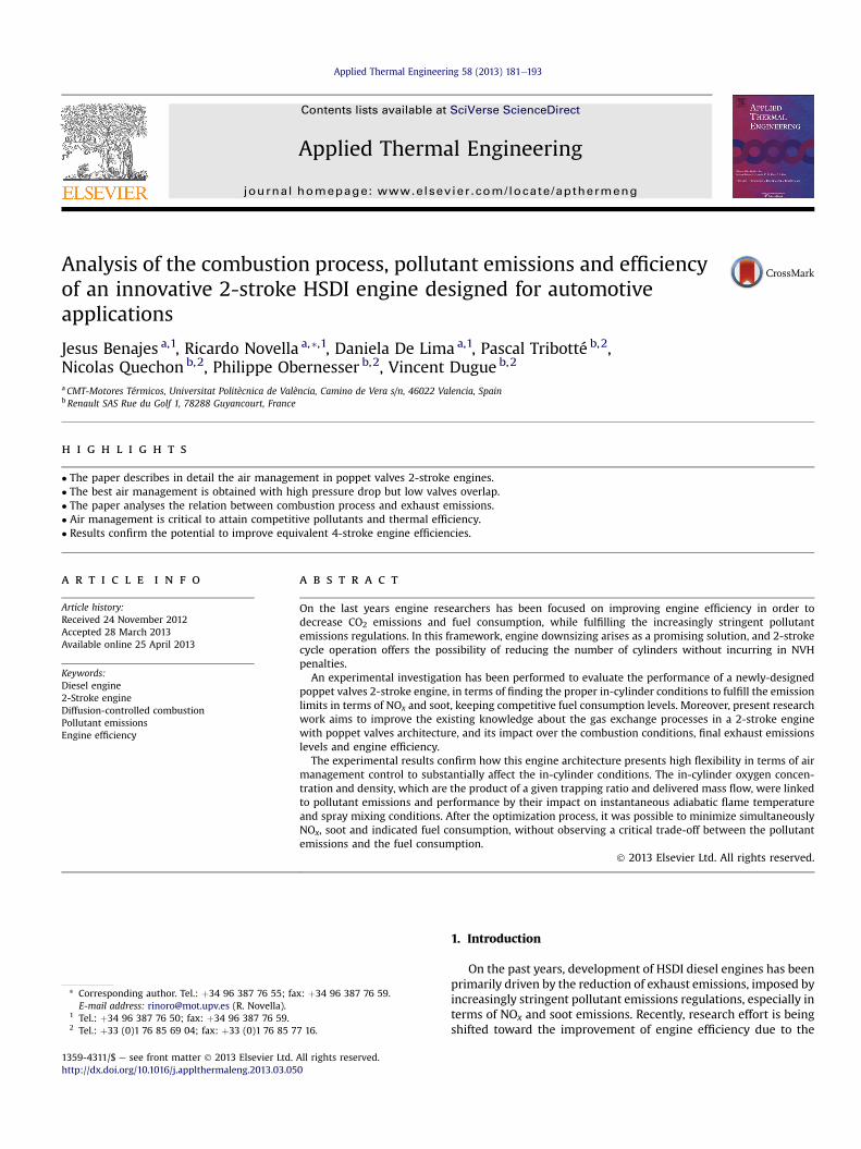
The cylinder head and combustion chamber geometry, shown inFig.1, were completely adapted to ensure a suitable in-cylinder flowpattern during 2-stroke operation, in order to optimize the scav-enging of burnt gases and to reduce the short-circuit losses of freshair going directly from the intake into the exhaust ports. The cyl-inder head geometry presents a staged roof for baffling the flow ofair between the intake and exhaust valves, forcing the air to followthe path of the cylinder wall toward the bottom of the cylinder.This geometry provides the best compromise between scavengingefficiency, acceptable permeability, and convenient combustionchamber geometry [17].
The engine is equipped with an hydraulic cam-driven VariableValve Timing system, allowing a flexibility of 30� on both intakeand exhaust valve timings independently from the mechanical camtiming. The flexibility of the VVT system is shown in Fig. 2, wherethe intake and exhaust cam lift laws have been included for thenominal phasing angle and also for the two extreme, minimum andmaximum, timing positions. Then, the effective compression ratio,overlap between intake and exhaust, and effective expansionratio can be modified by adjusting the valve timing angles. Theoptimum intake/exhaust camshaft configuration for this engine
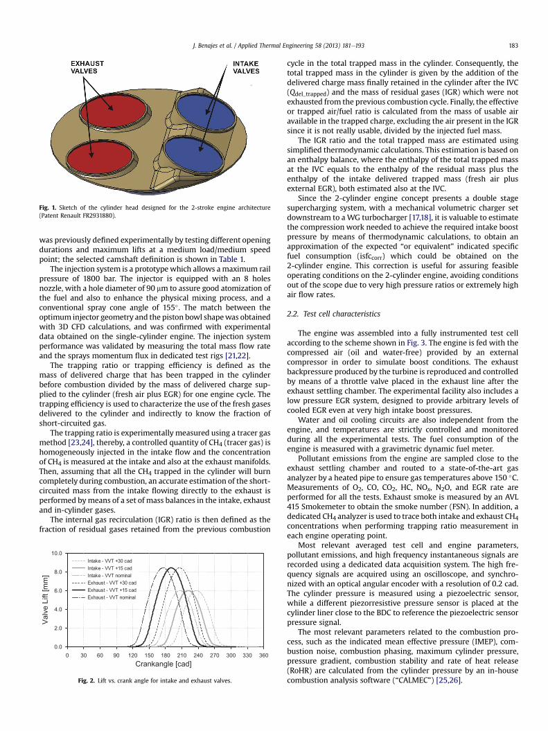
Fig. 1. Sketch of the cylinder head designed for the 2-stroke engine architecture(Patent Renault FR2931880).
J. Benajes et al. / Applied Thermal Engineering 58 (2013) 181e193 183
was previously defined experimentally by testing different openingdurations and maximum lifts at a medium load/medium speedpoint; the selected camshaft definition is shown in Table 1.
The injection system is a prototypewhich allows amaximum railpressure of 1800 bar. The injector is equipped with an 8 holesnozzle, with a hole diameter of 90 mm to assure good atomization ofthe fuel and also to enhance the physical mixing process, and aconventional spray cone angle of 155�. The match between theoptimum injector geometry and the piston bowl shapewas obtainedwith 3D CFD calculations, and was confirmed with experimentaldata obtained on the single-cylinder engine. The injection systemperformance was validated by measuring the total mass flow rateand the sprays momentum flux in dedicated test rigs [21,22].
The trapping ratio or trapping efficiency is defined as themass of delivered charge that has been trapped in the cylinderbefore combustion divided by the mass of delivered charge sup-plied to the cylinder (fresh air plus EGR) for one engine cycle. Thetrapping efficiency is used to characterize the use of the fresh gasesdelivered to the cylinder and indirectly to know the fraction ofshort-circuited gas.
The trapping ratio is experimentally measured using a tracer gasmethod [23,24], thereby, a controlled quantity of CH4 (tracer gas) ishomogeneously injected in the intake flow and the concentrationof CH4 is measured at the intake and also at the exhaust manifolds.Then, assuming that all the CH4 trapped in the cylinder will burncompletely during combustion, an accurate estimation of the short-circuited mass from the intake flowing directly to the exhaust isperformed bymeans of a set of mass balances in the intake, exhaustand in-cylinder gases.
The internal gas recirculation (IGR) ratio is then defined as thefraction of residual gases retained from the previous combustion
0 30 60 90 120 150 180 210 240 270 300 330 360Crankangle [cad]
0.0
2.0
4.0
6.0
8.0
10.0
ValveLift[mm]
Intake - VVT +30 cadIntake - VVT +15 cadIntake - VVT nominalExhaust - VVT +30 cadExhaust - VVT +15 cadExhaust - VVT nominal
Fig. 2. Lift vs. crank angle for intake and exhaust valves.
cycle in the total trapped mass in the cylinder. Consequently, thetotal trapped mass in the cylinder is given by the addition of thedelivered charge mass finally retained in the cylinder after the IVC(Qdel_trapped) and the mass of residual gases (IGR) which were notexhausted from the previous combustion cycle. Finally, the effectiveor trapped air/fuel ratio is calculated from the mass of usable airavailable in the trapped charge, excluding the air present in the IGRsince it is not really usable, divided by the injected fuel mass.
The IGR ratio and the total trapped mass are estimated usingsimplified thermodynamic calculations. This estimation is based onan enthalpy balance, where the enthalpy of the total trapped massat the IVC equals to the enthalpy of the residual mass plus theenthalpy of the intake delivered trapped mass (fresh air plusexternal EGR), both estimated also at the IVC.
Since the 2-cylinder engine concept presents a double stagesupercharging system, with a mechanical volumetric charger setdownstream to aWG turbocharger [17,18], it is valuable to estimatethe compression work needed to achieve the required intake boostpressure by means of thermodynamic calculations, to obtain anapproximation of the expected “or equivalent” indicated specificfuel consumption (isfccorr) which could be obtained on the2-cylinder engine. This correction is useful for assuring feasibleoperating conditions on the 2-cylinder engine, avoiding conditionsout of the scope due to very high pressure ratios or extremely highair flow rates.
2.2. Test cell characteristics
The engine was assembled into a fully instrumented test cellaccording to the scheme shown in Fig. 3. The engine is fed with thecompressed air (oil and water-free) provided by an externalcompressor in order to simulate boost conditions. The exhaustbackpressure produced by the turbine is reproduced and controlledby means of a throttle valve placed in the exhaust line after theexhaust settling chamber. The experimental facility also includes alow pressure EGR system, designed to provide arbitrary levels ofcooled EGR even at very high intake boost pressures.
Water and oil cooling circuits are also independent from theengine, and temperatures are strictly controlled and monitoredduring all the experimental tests. The fuel consumption of theengine is measured with a gravimetric dynamic fuel meter.
Pollutant emissions from the engine are sampled close to theexhaust settling chamber and routed to a state-of-the-art gasanalyzer by a heated pipe to ensure gas temperatures above 150 �C.Measurements of O2, CO, CO2, HC, NOx, N2O, and EGR rate areperformed for all the tests. Exhaust smoke is measured by an AVL415 Smokemeter to obtain the smoke number (FSN). In addition, adedicated CH4 analyzer is used to trace both intake and exhaust CH4concentrations when performing trapping ratio measurement ineach engine operating point.
Most relevant averaged test cell and engine parameters,pollutant emissions, and high frequency instantaneous signals arerecorded using a dedicated data acquisition system. The high fre-quency signals are acquired using an oscilloscope, and synchro-nized with an optical angular encoder with a resolution of 0.2 cad.The cylinder pressure is measured using a piezoelectric sensor,while a different piezorresistive pressure sensor is placed at thecylinder liner close to the BDC to reference the piezoelectric sensorpressure signal.
The most relevant parameters related to the combustion pro-cess, such as the indicated mean effective pressure (IMEP), com-bustion noise, combustion phasing, maximum cylinder pressure,pressure gradient, combustion stability and rate of heat release(RoHR) are calculated from the cylinder pressure by an in-housecombustion analysis software (“CALMEC”) [25,26].

Table 2Experimental test conditions and emissions and noise limits.
Engine speed 1500 rpmIMEP 5.5 barInjection pressure 900 barSoI pilot injection �19 cad aTDCSoI main injection (adjusted) �9 cad aTDCIVC/VVT position 259.7 cad/(þ13)EVC/VVT position (range of variation
given by overlap)From 240.4 to 250.4 cad/(from þ18 to þ28)
Intake air temperature 35 �CCoolant and oil temperature 90 �CNOx limit 0.75 mg/sHC limit 0.65 mg/sCO limit 4.4 mg/sSoot limit 0.56 FSNNoise limit 89.9 dB
Fig. 3. Layout of the engine test cell.
J. Benajes et al. / Applied Thermal Engineering 58 (2013) 181e193184
3. Methodology
In order to evaluate the performance of this innovative 2-strokeHSDI poppet-valves engine concept on a strictly controlled testenvironment, it was necessary to define a fast and efficient exper-imental test methodology, which was based on isolating the opti-mization process of the air management parameters from that ofthe injection parameters. This optimization is focused on findingthe most suitable in-cylinder conditions necessary to fulfill theemission limits, especially in terms of NOx and soot, while mini-mizing the fuel consumption as much as possible. Based on thisobjective, a dedicate test campaign for studying the air manage-ment characteristics was designed in order to easily identify thecause/effect relations of the air management parameters over thein-cylinder conditions, and consequently over combustion devel-opment and exhaust emissions. A Design of Experiment (DOE)methodology is proposed in order to find the best settings for theair management related parameters for a given engine operatingcondition. A Central Composite Design (CCD) was selected to buildthe test plan since this design allows modeling the responses usinga quadratic equation, taking into account all possible second orderinteractions between the factors.
The main air management settings chosen as factors for the airmanagement DOE are the EGR rate, intake pressure, pressure dif-ference between intake and exhaust (DP) and valve overlap dura-tion. The intake valve timing was kept constant at a valuepreviously obtained by a parametric optimization, so the exhaustvalve timing is defined consequently depending on the desiredvalve overlap duration.
The engine operating condition chosen for this experimentaltest campaign, corresponds with a medium speed (1500 rpm) and
medium load (5.5 bar of IMEP) point, and the most relevantexperimental conditions as well as the expected targets in terms ofexhaust emissions and noise are described in Table 2. The ranges ofvariation for the air management settings included as factors in theDOE are included in Table 3, and they were selected based onpreliminary calculations with a 1D wave action model combinedwith fast screening parametric tests performed on the engine. Thetests were all performed with a constant injection pressure of900 bar and with 2 injection events, one small pilot injection of2.2 mg/st placed at �19 cad aTDC, and a main injection, for whichthe injected quantity and timing (SoI) are adjusted to maintain aconstant value of IMEP of 5.5 bar and a CA50 phased at 3 cad aTDC.
The pollutant emissions and noise limits imposed along thisinitial evaluation of the engine concept corresponds to the Euro

Table 3Air management related parameters included in the DOE, and their ranges ofvariation.
Air management factor From To
EGR rate [%] 26 36Intake pressure [bar] 1.6 1.7DP [bar] 0.3 0.5Overlap [cad] 70 80
J. Benajes et al. / Applied Thermal Engineering 58 (2013) 181e193 185
5 levels measured on a 4-stroke engine with equivalent charac-teristics in terms of unitary displacement and geometry.
4. Results and discussion
4.1. DOE validation
The results obtained after performing 36 points of the testmatrix included in the design of experiments, are useful forproviding an overview of the behavior of several measured engineresponses, and their relations with the four selected air manage-ment factors. Table 4 shows the most important quality indicatorsto check the fit of the quadratic mathematical model for eachmeasured or calculated response.
The regression coefficient is very close to 1 (“perfect fit”) in thecase of all the responses directly measured on the engine, as in thecase of trapping ratio, delivered fresh air, NOx and soot emissions.Concerning fuel consumption, since the measured range of varia-tion was small, around 5%, it was more difficult to assure a perfectfit due to some small dispersion, less than 1%, on the measuredcentral points of the DOE. Estimated parameters such as in-cylinderrichness, oxygen concentration at the IVC, adiabatic flame tem-peratures and spray mixing capacity have slightly lower, but stillacceptable, regression coefficients than the directly measured re-sponses, since they are derived from the measured responsesthrough thermodynamic calculations or combustion analysis cal-culations. In any case, the statistical models are well fitted to theexperimental data and they are useful to observe important trendsbetween the air management parameters and several engine re-sponses with a high degree of confidence. Moreover, the use of thestatistical model of the responses will not only help understandingthe physical phenomena related to air management and combus-tion conditions, but also will provide the guidelines for the opti-mization process in terms of fuel consumption and exhaustemissions.
Table 4Statistical analysis of the most important responses.
Measured/modeled responses R2 [�] Standarddeviationof error
Mean absoluteerror
Trapping ratio [%] 0.9899 0.2095 0.2712Delivered fresh air [kg/h] 0.9975 0.0815 0.0858Effective in-cylinder richness [�] 0.9697 0.0030 0.0041Oxygen concentration at IVC [%] 0.9838 0.0394 0.0551Max adiabatic flame
temperature [K]0.9689 4.4726 4.9189
Adiabatic flame temperature at80%MBF [K]
0.9708 4.5702 5.6412
Gas mixing capacity (ACT�1) at80%MFB [A.U]
0.9539 0.0093 0.0117
NOx emissions [mg/s] 0.9969 0.0121 0.0135Soot emissions [FSN] 0.9894 0.0206 0.0273Indicated specific fuel consumption
[g/kWh]0.9354 0.2442 0.3374
Corrected indicated specific fuelconsumption [g/kWh]
0.9742 0.3576 0.4486
4.2. Air management process
Two stroke poppet valves architecture inherently exhibits lowtrapping efficiencies compared to four stroke engines, due to therequiredpositivepressuredifferencebetween the intakeandexhaust,the longoverlap duration, and proximity between intake and exhaustvalves (even with masking on the intake); making very difficult tobalance the air charging of the cylinder with the short-circuit losses,while simultaneously ensuring proper scavenging of the burnt gases.The experimental results showed howall DOEmeasured pointswerecomprised inside a range of variation from 60% to 80% of trappingratio,whichwas subsequently limited along the optimizationprocessto 65%e80%, in order to avoid extremely lowvalues of trapping ratios,which are not feasible for the final engine application.
Concerning the IGR ratio, previous studies showed howdecreasing trapping efficiency improved the scavenging of burntgases out of the cylinder, until reaching a practical lower limit,where it was not possible to decrease furthermore the IGR [17]. Inthis research, the ranges for the air management parameters werepre-selected in advance to assure the lowest percentage of IGR ratioas possible. Additionally, since it is necessary to introduce high levelsof EGR to achieve the NOx limit, the ranges chosen for the overlap,DPand intake pressure were slightly overestimated toward high airflow rates andmedium-to-low trapping ratios. Within these ranges,the IGR ratio remained approximately constant for all the measuredpoints at around 30%. Nevertheless, even operating with lowertrapping efficiencies and higher residual gas fraction than in4-stroke engines, suitable in-cylinder conditions can be achieved toassure high combustion efficiencies and competitive indicated effi-ciencies comparable to those obtained in 4-stroke engines.
Fig. 4 shows the relation between trapping ratio and the deliv-ered charge mass (fresh air plus EGR) supplied to the cylinder withDP, Fig. 4a, and overlap, Fig. 4b. According to these figures, due tothe reduced cylinder head permeability in the intake side caused bythe masking surface, DP needs to be increased to attain highQdelivered levels, but the overlap should be decreased to keep suit-able levels of trapping ratio, since the short-circuited mass flowflowing from the intake to the exhaust depends mainly on thewidth of the valve overlap. In fact, the grading observed in Fig. 4confirms how the best combination of Qdelivered, 40 kg/h, andtrapping ratio, 70%, is attained at the highest DP and the narrowervalve overlap. Intake pressure has some effect on trapping ratio, butmuch lower than in the case of DP and valve overlap, furthermore,the EGR rate has a very small effect on trapping ratio. Finally, resultsconfirm how the trapping ratio will result from the simultaneouscombination of the four factors, being DP and overlap the two mostinfluential factors.
Focusing on the in-cylinder conditions at the intake valve clos-ing, Fig. 5 a shows how the highest levels of YO2 IVC (16%) areattained for trapping ratios ranging between 65% and 75%while thelowest levels (13%) are attained for high trapping ratios, whereQdelivered is compromised. Additionally, the reduction in YO2 IVCdirectly caused by the EGR explains the different values of YO2 IVCobserved for the same combination of delivered mass flow andtrapping ratio.
The effective in-cylinder equivalence ratio (f_cyl_eff) is calculatedfrom the stoichiometric air/fuel ratio, the injected fuel quantity andthe usable air available in the trapped charge. It is also important toremark that the injected fuel quantity was adjusted along thepoints of the DOE for keeping constant the IMEP value, compen-sating the differences in cycle and combustion efficiencies, whichhas a direct impact on the f_cyl_eff. Fig. 5 b illustrates how in general,f_cyl_eff ranges from 0.6 to 0.8 and follows the usual opposite trendcompared to YO2 IVC, so those points with low YO2 IVC have highf_cyl_eff levels.
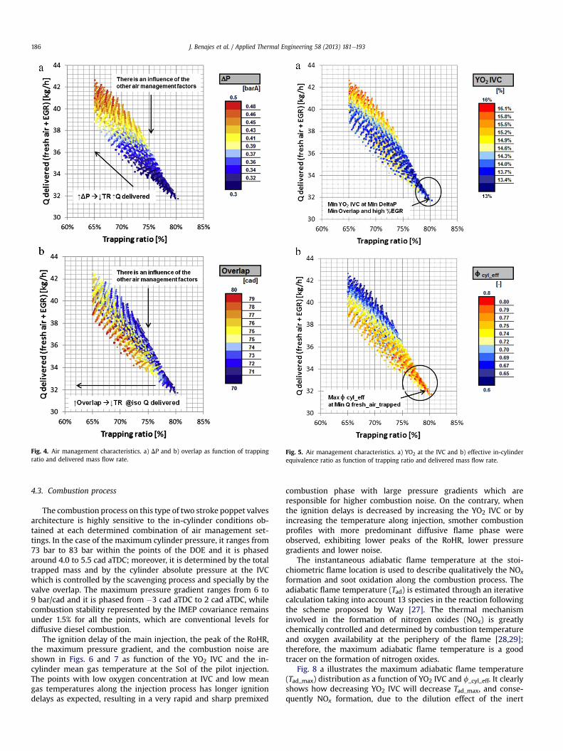
Fig. 5. Air management characteristics. a) YO2 at the IVC and b) effective in-cylinderequivalence ratio as function of trapping ratio and delivered mass flow rate.
Fig. 4. Air management characteristics. a) DP and b) overlap as function of trappingratio and delivered mass flow rate.
J. Benajes et al. / Applied Thermal Engineering 58 (2013) 181e193186
4.3. Combustion process
The combustion process on this type of two stroke poppet valvesarchitecture is highly sensitive to the in-cylinder conditions ob-tained at each determined combination of air management set-tings. In the case of the maximum cylinder pressure, it ranges from73 bar to 83 bar within the points of the DOE and it is phasedaround 4.0 to 5.5 cad aTDC; moreover, it is determined by the totaltrapped mass and by the cylinder absolute pressure at the IVCwhich is controlled by the scavenging process and specially by thevalve overlap. The maximum pressure gradient ranges from 6 to9 bar/cad and it is phased from �3 cad aTDC to 2 cad aTDC, whilecombustion stability represented by the IMEP covariance remainsunder 1.5% for all the points, which are conventional levels fordiffusive diesel combustion.
The ignition delay of the main injection, the peak of the RoHR,the maximum pressure gradient, and the combustion noise areshown in Figs. 6 and 7 as function of the YO2 IVC and the in-cylinder mean gas temperature at the SoI of the pilot injection.The points with low oxygen concentration at IVC and low meangas temperatures along the injection process has longer ignitiondelays as expected, resulting in a very rapid and sharp premixed
combustion phase with large pressure gradients which areresponsible for higher combustion noise. On the contrary, whenthe ignition delays is decreased by increasing the YO2 IVC or byincreasing the temperature along injection, smother combustionprofiles with more predominant diffusive flame phase wereobserved, exhibiting lower peaks of the RoHR, lower pressuregradients and lower noise.
The instantaneous adiabatic flame temperature at the stoi-chiometric flame location is used to describe qualitatively the NOx
formation and soot oxidation along the combustion process. Theadiabatic flame temperature (Tad) is estimated through an iterativecalculation taking into account 13 species in the reaction followingthe scheme proposed by Way [27]. The thermal mechanisminvolved in the formation of nitrogen oxides (NOx) is greatlychemically controlled and determined by combustion temperatureand oxygen availability at the periphery of the flame [28,29];therefore, the maximum adiabatic flame temperature is a goodtracer on the formation of nitrogen oxides.
Fig. 8 a illustrates the maximum adiabatic flame temperature(Tad_max) distribution as a function of YO2 IVC and f_cyl_eff. It clearlyshows how decreasing YO2 IVC will decrease Tad_max, and conse-quently NOx formation, due to the dilution effect of the inert

Fig. 7. Combustion characteristics. a) Maximum pressure gradient and b) noise asfunction of the YO2 IVC and the gas temperature at the SoI of the pilot injection.
Fig. 6. Combustion characteristics. a) Ignition delay of the main injection and b)maximum RoHR as function of the YO2 IVC and the gas temperature at the SoI of thepilot injection.
J. Benajes et al. / Applied Thermal Engineering 58 (2013) 181e193 187
exhaust gas inside the combustion chamber, but as a counterpartf_cyl_eff increases.
The late diffusive stage of combustion, between the EoI and theEoC, is fundamental for defining the final soot emissions level,because the soot oxidation process is substantially slowed downdue to the fast decrease of in-cylinder gas temperature and density.The soot formed inside the flame is oxidized outside the flamearound the stoichiometric zone, by the attack of OH-radicals whichare thought to be the major mechanism responsible for sootoxidation in near stoichiometric conditions as in the case of diffu-sion flames [30]. Therefore, high local temperatures at the latestages of combustion and presence of oxygen are mandatory toincrease the rate of formation of OH-radicals and enhance thechemical process of soot oxidation [31,32]. The adiabatic flametemperature at the point of 80% of fuel mass burnt fraction (Tad_80%MBF) has been used by various authors to describe the late sootoxidation process [33e35], so it was selected to be representative ofthe late oxidation temperature.
Fig. 8b shows how Tad_80%MBF follows a similar trend thanTad_max, so reducing the maximum adiabatic temperature bydecreasing the YO2 IVC leads to an equivalent reduction in thetemperature at the final stages of combustion, consequently
punishing the soot oxidation process as expected. Note how belowcertain YO2 IVC level, approximately 15%, the trend followed byTad_80%MBF in Fig. 8b is not vertical since the effect of the mixing rateof the fuel spray over the Tad_80%MBF starts to gain relevance.
Focusing on the mixing process, in diesel sprays it is ruledmainly by the injection parameters, the fuel properties and the in-cylinder conditions, specifically oxygen concentration and gasdensity. The characteristic time required for a fuel particle injectedin a steady state non-reactive gas jet to reach the stoichiometricconditions is given following the Equation (1) [36]:
tmix ¼ K1
�ðA=FÞst,
YO2 atmYO2
�2,B0
u0,
ffiffiffiffiffirfr
r(1)
where K1 is a constant that depends on the engine and its config-uration, (A/F)st is the stoichiometric airefuel ratio, YO2 atm and YO2corresponds to the oxygen mass concentration at ambient condi-tions and inside the cylinder, u0 is the injection velocity, B0 theinjector nozzle diameter and rf and r are respectively the density ofthe fuel and the density of the gas inside the cylinder.
Then, the mixing capacity is defined as the inverse of thecharacteristic mixing time, and it serves as a good indicator of the
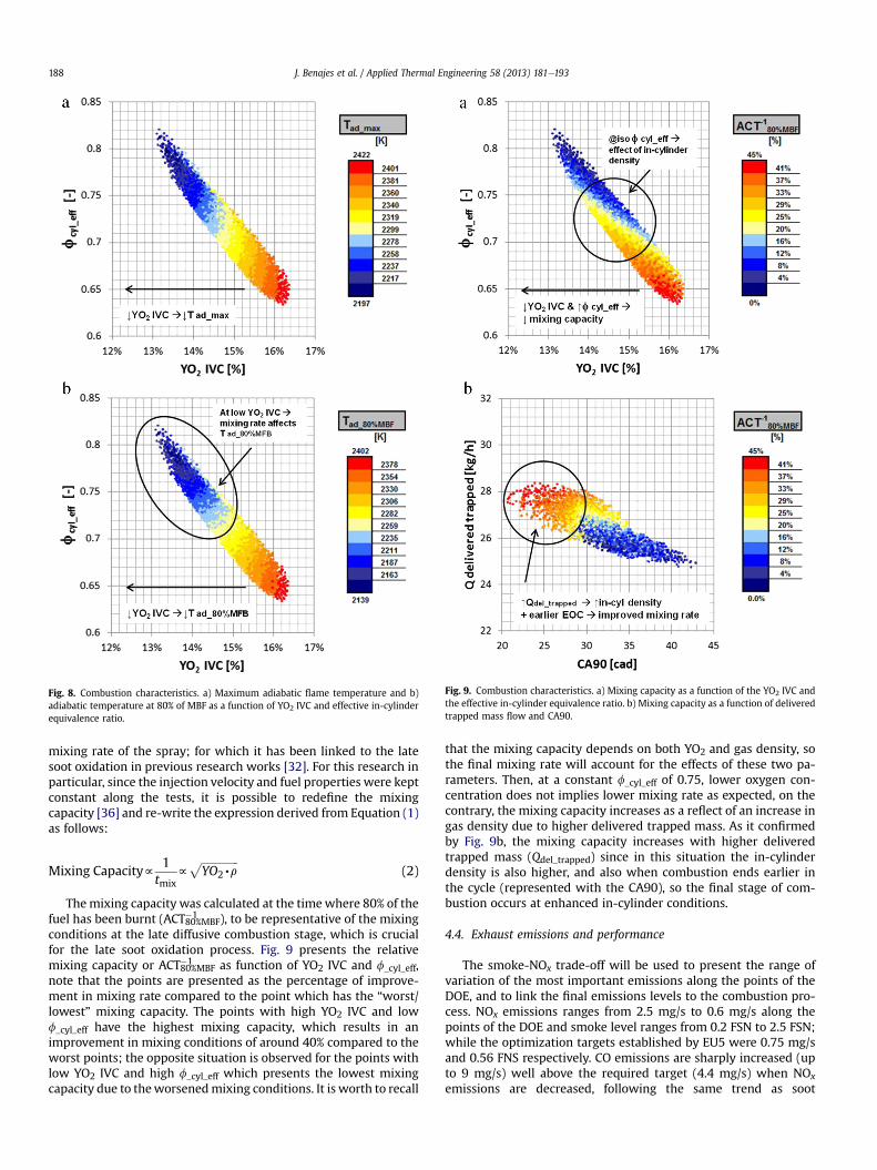
Fig. 9. Combustion characteristics. a) Mixing capacity as a function of the YO2 IVC andthe effective in-cylinder equivalence ratio. b) Mixing capacity as a function of deliveredtrapped mass flow and CA90.
Fig. 8. Combustion characteristics. a) Maximum adiabatic flame temperature and b)adiabatic temperature at 80% of MBF as a function of YO2 IVC and effective in-cylinderequivalence ratio.
J. Benajes et al. / Applied Thermal Engineering 58 (2013) 181e193188
mixing rate of the spray; for which it has been linked to the latesoot oxidation in previous research works [32]. For this research inparticular, since the injection velocity and fuel properties were keptconstant along the tests, it is possible to redefine the mixingcapacity [36] and re-write the expression derived from Equation (1)as follows:
Mixing Capacityf1
tmixf
ffiffiffiffiffiffiffiffiffiffiffiffiffiffiYO2,r
p(2)
Themixing capacity was calculated at the timewhere 80% of thefuel has been burnt (ACT80%MBF
�1 ), to be representative of the mixingconditions at the late diffusive combustion stage, which is crucialfor the late soot oxidation process. Fig. 9 presents the relativemixing capacity or ACT80%MBF
�1 as function of YO2 IVC and f_cyl_eff,note that the points are presented as the percentage of improve-ment in mixing rate compared to the point which has the “worst/lowest” mixing capacity. The points with high YO2 IVC and lowf_cyl_eff have the highest mixing capacity, which results in animprovement in mixing conditions of around 40% compared to theworst points; the opposite situation is observed for the points withlow YO2 IVC and high f_cyl_eff which presents the lowest mixingcapacity due to theworsenedmixing conditions. It is worth to recall
that the mixing capacity depends on both YO2 and gas density, sothe final mixing rate will account for the effects of these two pa-rameters. Then, at a constant f_cyl_eff of 0.75, lower oxygen con-centration does not implies lower mixing rate as expected, on thecontrary, the mixing capacity increases as a reflect of an increase ingas density due to higher delivered trapped mass. As it confirmedby Fig. 9b, the mixing capacity increases with higher deliveredtrapped mass (Qdel_trapped) since in this situation the in-cylinderdensity is also higher, and also when combustion ends earlier inthe cycle (represented with the CA90), so the final stage of com-bustion occurs at enhanced in-cylinder conditions.
4.4. Exhaust emissions and performance
The smoke-NOx trade-off will be used to present the range ofvariation of the most important emissions along the points of theDOE, and to link the final emissions levels to the combustion pro-cess. NOx emissions ranges from 2.5 mg/s to 0.6 mg/s along thepoints of the DOE and smoke level ranges from 0.2 FSN to 2.5 FSN;while the optimization targets established by EU5 were 0.75 mg/sand 0.56 FNS respectively. CO emissions are sharply increased (upto 9 mg/s) well above the required target (4.4 mg/s) when NOx
emissions are decreased, following the same trend as soot

J. Benajes et al. / Applied Thermal Engineering 58 (2013) 181e193 189
emissions, as shown in Fig. 10; while HC emissions are below thetarget (0.65 mg/s) in all the points; which is finally translated incombustion efficiencies above 99% for all the range of the DOE.
Fig. 11 shows both Tad_max and Tad_80%MBF placed on the smokeeNOx trade off. The points with high Tad_max, which are those pointswith high YO2 IVC and low f_cyl_eff, have a high rate of formation ofNOx emissions as explained before, and additionally, since Tad_80%MBF is also high, the late soot oxidation process is enhancedresulting in low levels of soot emissions. Decreasing Tad_max byintroducing EGR or affecting the air management conditions leadsto a consequent decrease on Tad_80%MBF, reason why thermal NOx
rate of formation is slowed down together with the oxidation sootrate. The best compromise on the smokeeNOx trade off, are thosepoints where Tad_max is relatively low but the mixing conditions areenhanced, favoring the rate of combustion and the late sootoxidation process, as shown in Fig. 9, resulting in low soot levels.This is shown in Fig. 12, where the percentage of improvement inACT80%MBF
�1 confirms how the points with simultaneous lowNOx andlow smoke level have around 25% highermixing capacity comparedto the points with low NOx but high smoke emissions.
Fig. 10. Exhaust emissions and performance. a) CO and b) HC as function of smoke andNOx emissions.
Fig. 11. Exhaust emissions and performance. a) Maximum adiabatic flame temperatureand b) adiabatic flame temperature at 80% of the MBF as function of smoke and NOx
emissions.
Additionally, Fig. 10 shows how CO emissions, which are alsocontrolled by the late oxidation processes, followed the same trendas soot/smoke emissions. This result evidences the direct relationbetween the conditions at the final stages of combustion (Tad_80%MBF and ACT80%MBF
�1 ), the oxidation processes and the final CO andsoot emissions level.
In terms of engine performance, Fig. 13a illustrates how thecombustion related parameters are directly linked with bothexhaust emissions and engine efficiency. The points with highTad_max and enhanced mixing process have low smoke emissions,medium-to-high NOx levels and low isfc, mainly because combus-tion takes place in a favorable environment for the fuel-energyconversion processes, where the fresh air trapped mass flow ishigh and YO2 IVC is high as well, while f_cyl_eff is low.
The corrected indicated specific fuel consumption expected atthe two cylinder engine, (isfccorr) is shown in Fig. 13b, and thepoints with low smoke and high NOx emissions, which previouslyhad the lowest isfc, now presents higher corrected isfccorr, afterconsidering the compression work needed to achieve the intakepressure and the required delivered air flow rate. To decreaseisfccorr it is necessary to find a good combination of initially low isfc

Fig. 12. Exhaust emissions and performance. Mixing capacity as a function of smokeand NOx emissions.
Fig. 13. Exhaust emissions and performance. a) isfc and b) isfccorr as a function ofsmoke and NOx emissions.
J. Benajes et al. / Applied Thermal Engineering 58 (2013) 181e193190
with a medium-to-low intake air flow rate which does not requiretoo high compression work. In the case of points with high smokeemissions, even when the delivered intake flow rate is lower (highf_cyl_eff and low YO2 IVC) the worsened combustion conditionsleads to a higher initial indicated fuel consumption, therefore, thegain in compressionwork does not compensate the losses in engineefficiency.
The objective of the final stage in the DOE analysis is to find thebest trade-off between exhaust emissions, referring to NOx andsmoke emissions mostly, and indicated fuel consumption. After-ward, an optimum point is selected considering the air manage-ment settings and measured experimentally on the engine, tocheck the accuracy on the prediction performed with the statisticalmodel for the selected responses.
4.5. Optimization of emissions and performance
The aim of the optimization process is to find the best possiblecombination between NOx/soot emissions and isfc or isfccorr withinthe ranges of the DOE. A merit or objective function, identified asMF and shown in Equation (3), has been selected for this purposeand it requires a target or objective value for each response, andspecific adjustment coefficients to place more emphasis on satis-fying one particular response among the others. This function al-lows for each combination of input parameters to be comparedbased on the desired target or objectives for the responses. Largervalues of the merit function correspond to those combinations ofthe responses that better satisfy the desired objectives [37].
MF ¼1000,
PiðaiÞ
Pi
�ai,e
biRV�OVi
OVi
� (3)
In Equation (3) a and b are adjustment coefficients to favor theoptimization of a desired response, RV is the response value, OV isthe objective or target value for the response and i is the selectedresponse.
Two merit functions were calculated to find the best combina-tion between NOx, soot and isfc (MFNOx,soot,isfc in Fig. 14a) and alsobetween NOx, soot and isfccorr (MFNOx,soot,isfccorr in Fig. 14b). Thesameweight or emphasis on the optimizationwas applied for the 3responses; however, in the case of emissions the percentage of NOx
and soot variation is much higher within the space of the DOE thanin the case of fuel consumption.
From Fig. 14a, it is clear how the maximum of the merit functionappears always at the best compromise between soot and NOx
emissions, which means that it is possible to minimize simulta-neously NOx, soot and indicated fuel consumption without the ex-istence of a trade-off between emissions and consumption.Moreover, in the case of isfccorr, even when the optimum point forminimum NOx and minimum soot does not corresponds to the op-timum for isfccorr previously observed in Fig. 13b, the simultaneouscombination between the three responses shown in Fig. 14b corre-sponds again with the same corner of the NOxesoot trade off, beingthe best possible combination of the three responses since it max-imizes the merit function. Then, it is possible to optimize NOx, sootand engine isfc simultaneously, increasing isfccorr by less than 5%.
Finally, this optimization methodology and results were vali-dated by measuring the two optimums experimentally on the en-gine. Table 5 shows the error between the observed and predictedvalues for the two different optimum points obtained along theoptimization process. These results confirm how the percentage oferror between the predicted and measured responses is extremelylow, below 2%, for almost every response and only the smoke

Table 6Measured responses at optimum point #2.
Measured responses Optimum #2
Trapping ratio [%] 67.9%IGR rate [%] 36.4%Effective in-cylinder equivalence ratio [�] 0.71EGR rate [%] 35%YO2 at the IVC [%] 14.3%NOx [mg/s] 1.09Smoke [FSN] 0.43Combustion efficiency [%] 99.4%Indicated specific fuel consumption [g/kWh] 187.61Indicated efficiency [%] 45.6%
Fig. 14. Optimization of the DOE. a) Merit function based on NOx, smoke and isfc. b)Merit function based on NOx, smoke and isfccorr.
J. Benajes et al. / Applied Thermal Engineering 58 (2013) 181e193 191
emissions differs by 5%. Thus, it has been proven that the testingmethodology, the statistical analysis and the optimization criteriahave performed with high accuracy, providing the main guidelinesto find the optimum operating conditions for achieving the ex-pected optimization objectives. Finally, the most interestingmeasured responses obtained at the optimum point #2 are pre-sented below in Table 6.
During the statistical analysis and optimization process of theDOE, it has been demonstrated how the air management conditionshave an important impact on the combustion and emissions
Table 5Validation of the statistical models at two different optimum points.
Measured/modeled responses Error between modeled/measured
Opt #1 Opt #2
Trapping ratio [%] 0.40% 1.36%Delivered fresh air [kg/h] 0.51% 1.05%NOx emissions [mg/s] 1.12% 1.82%Soot emissions [FSN] 0.55% 4.78%Indicated specific fuel consumption
[g/kWh]0.35% 0.44%
Corrected indicated specific fuelconsumption [g/kWh]
1.38% 0.82%
formation processes, on this type of 2-stroke engine architecture.Nevertheless, even with an intrinsic inefficient architecture for thescavenging process, it is possible to operate with the inherently lowtrapping efficiencies and high amount of residuals, to achieve theproper in-cylinder conditions required to provide a suitable com-bustion process with high combustion efficiencies and competitiveindicated fuel consumption. Table 6 shows how the concept engineperforms at the selected optimum point #2 after concluding theoptimization process. The engine operates with a relatively lowtrapping efficiency of 68%, has a 36% of IGR rate and f_cyl_eff equal to0.7 when introducing 35% of EGR. The combustion develops veryhigh efficiency (99%) and emissions levels are very close to the tar-gets with more competitive indicated efficiency (46%) than theequivalent 4-stroke engine (44%) at the same load/speed combina-tion. The final soot and NOx levels are very close to the expected EU5targets without performing the fine-tuning of the injection settings.
5. Conclusions
The present research has been focused on evaluating the per-formance of a newly-designed poppet valves 2-stroke engine interms of finding the proper in-cylinder conditions necessary to fulfillthe emission limits while keeping competitive fuel consumption.The engine architecture proved its potential to have high flexibilityin terms of air management control, valve timing, EGR and intakeboosting levels to substantially affect the in-cylinder conditions, andconsequently the combustion development which determines finalemissions level and indicated efficiency. The following main con-clusions can be extracted from this research work:
- The minimum effective in-cylinder equivalence ratio (f_cyl_eff),is obtained at the point with higher delivered trapped mass(Qdel_trapped), which appears as the product between the trap-ping ratio and the total delivered flow (Qdelivered). The twomostinfluential factors controlling the delivered trapped mass arethe pressure drop (DP) and valve overlap. The best combinationof trapping ratio and Qdel_trapped is obtained with the highestvalues of DP but with the lowest values of valves overlap.
- LowNOx emissions levels are attainable by reducing YO2 IVC andthen, Tad_max along the combustion process. In this 2-stroke en-gine, the YO2 IVC can be easily controlled by introducing externalEGR, but also by affecting the air management conditions.However, reducing Tad_max by decreasing the oxygen concen-tration without compensating with higher in-cylinder gas den-sity leads to a consequent decrease of the temperatures along thelate diffusive combustion stage (Tad_80%MBF), resulting in wors-ened soot oxidation process and higher final soot emissions.
- The final soot level is determined not only by the combustiontemperature at the late-combustion phase but also by themixing conditions at this late diffusion stage, being both crucialfor the late soot oxidation process. A higher delivered trapped

J. Benajes et al. / Applied Thermal Engineering 58 (2013) 181e193192
mass provides a higher in-cylinder density, enhancing themixing process and shortening the combustion duration, forwhich final soot emissions are largely reduced.
- The airmanagement conditions are critical to achieve the properin-cylinder conditions which provide suitable combustionenvironment to attain high combustion efficiencies andcompetitive indicated fuel consumption. After the optimizationprocess, it was possible to minimize simultaneously NOx, sootand indicated fuel consumption,without the existenceof a trade-off between the pollutant emissions and the fuel consumption.
- The methodology designed in this research was successfullyimplemented to optimize the fuel consumption and emissionslevels of a 2-stroke engine at the reported engine operatingcondition. The straight and general relations obtained after theanalysis of the results confirm how the best approach for un-derstanding the physical processes linked to 2-stroke engines,is to switch from particular engine operation settings to thefinal in-cylinder gas thermodynamic conditions, which latercontrols the combustion process development and final emis-sions level and efficiency. Thus, this methodology can beextrapolated to design and develop any 2-stroke engine,regardless of its particular architecture or displacement.
Finally, the results obtained along this first stage of evaluation,proved how it is possible to reach and improve the performance ofan equivalent 4-stroke engine with a 2-stroke poppet valves en-gine. The main trends and relations identified along this researchare useful to prepare the path toward future optimization of thisparticular engine concept to comply with more stringent regula-tions such as EU6.
Acknowledgements
This research has been sponsored by the European Union inframework of the POWERFUL project, seventh framework programFP7/2007e2013, theme 7, sustainable surface transport, grantagreement No. SCP8-GA-2009-234032. The authors gratefullyappreciate this support.
References
[1] T. Ryan, T. Callahan, Homogeneous charge compression ignition of diesel fuel,SAE Paper (1996), 961160.
[2] S. Kimura, H. Ogawa, Y. Matsui, Y. Enomoto, An experimental analysis of low-temperature and premixed combustion for simultaneous reduction of NOxand particulate emissions in direct injection diesel engines, InternationalJournal of Engine Research 3 (2002) 249e259.
[3] R. Kiplimo, E. Tomita, N. Kawahara, S. Yokobe, Effects of spray impingement,injection parameters, and EGR on the combustion and emission characteristicsof a PCCI diesel engine, Applied Thermal Engineering 37 (2012) 165e175.
[4] P. Miles, D. Choi, L. Pickett, I. Singh, N. Henein, B. RempelEwert, H. Yun,R. Reitz, Rate-limiting processes in late-injection, low temperature dieselcombustion processes, in: THIESEL Conference Proceedings (2004).
[5] K. Epping, S. Aceves, R. Bechtold, J. Dec, The potential of HCCI combustion forhigh efficiency and low emissions, SAE Paper (2002), 2002-01-1923.
[6] Q. Fang, J. Fang, J. Zhuang, Z. Huang, Influences of pilot injection and exhaustgas recirculation (EGR) on combustion and emissions in a HCCI-DI combustionengine, Applied Thermal Engineering 48 (2012) 97e104.
[7] J. Benajes, R. Novella, D. De Lima, N. Quechon, P. Obernesser, The potential ofhighly premixed combustion for pollutant control in an automotive two-stroke HSDI diesel engine, SAE Paper (2012), 2012-01-1104.
[8] J. Benajes, R. Novella, D. De Lima, N. Quechon, P. Obernesser, Implementation ofthe early injection highly premixed combustion concept in a two-stroke HSDIengine, in: SIA Diesel Powertrain Congress, Conference Proceedings (2012).
[9] T. Köfer, M. Lamping, H. Rohs, D. Adolph, S. Pischinger, The Future PowerDensity of HSDI Diesel Engines with Lowest Engine Out EmissionseA KeyElement for Upcoming CO2 Demands, Fisita, 2008, 2008-06-015.
[10] T. Körfer, M. Lamping, A. Kolbeck, S. Pischinger, D. Adolph, H. Busch, Potentialof modern diesel engines with lowest raw emissions e a key factor for futureCO2 reduction, SAE Paper (2009), 2009-26-0025.
[11] M. Thirouard, P. Pacaud, Increasing power density in HSDI engines as anapproach for engine downsizing, SAE Int. J. Engines 3 (2010) 56e71.
[12] J. McCartney, R. Day, A. Ward, C. Rouaud, P. Newman, J. Borges, Y. Baubet,S. Lindsey, Integrated technologies for cost effective CO2 reduction, in: SIADiesel Powertrain Congress, Conference Proceedings (2012).
[13] A. Lefebvre, S. Guilain, Study of different boosting technologies and their effecton the transient response of a very downsized diesel engine, in: SIA DieselPowertrain Congress, Conference Proceedings (2012).
[14] M. Thirouard, S. Mendez, P. Pacaud, V. Chmielarczyk, D. Ambrazas, C. Garsi,F. Lavoisier, B. Barbeau, Potential to improve specific power using very highinjection pressure in HSDI diesel engines, SAE Paper (2009), 2009-01-1524.
[15] H. Ecker, M. Schwaderlapp, D. Gill, Downsizing of diesel engines: 3-cylinder/4-cylinder, SAE Paper (2000), 2000-01-0990.
[16] S. Brandl, B. Graf, A. Rust, NVH challenges and solutions for vehicles with lowCO2 emission, SAE International Journal of Passenger CarseMechanical Sys-tems 5 (2012) 1084e1090.
[17] P. Tribotte, F. Ravet, V. Dugue, P. Obernesser, N. Quechon, J. Benajes, R. Novella,D. De Lima, Two stroke diesel engine. Promising solution to reduce CO2 emis-sions, ProcediaeSocial and Behavioral Sciences 48 (2012) 2295e2314.
[18] L. Pohorelsky, P. Brynych, J. Macek, P. Vallaude, J. Ricaud, P. Obernesser,P. Tribotte, Air system conception for a downsized two-stroke diesel engine,SAE Paper (2012), 2012-01-0831.
[19] J. Heywood, E. Sher, The Two Stroke Cycle Engine: Its Development, Operationand Design, SAE International, Taylor and Francis, Warrendale, Pennsylvania,1999.
[20] G. Blair, The Basic Design of Two-stroke Engines, SAE International, Warren-dale, Pennsylvania, 1990.
[21] R. Payri, F. Salvador, J. Gimeno, G. Bracho, A new methodology for correctingthe signal cumulative phenomenon on injection rate measurements, Experi-mental Techniques 32 (2008) 46e49.
[22] R. Payri, J. Garcia, F. Salvador, J. Gimeno, Using spray momentum flux mea-surements to understand the influence of diesel nozzle geometry on spraycharacteristics, Fuel 84 (2005) 551e561.
[23] D. Olsen, G. Hutcherson, B. Wilson, C. Mitchell, Development of the tracer gasmethod for large bore natural gas engines: part 1 e method validation,Journal of Engineering for Gas Turbines and Power 124 (3) (2002) 678e685.
[24] D. Olsen, G. Hutcherson, B. Wilson, C. Mitchell, Development of the tracer gasmethod for large bore natural gas engines: part 2 e measurement of scav-enging parameters, Journal of Engineering for Gas Turbines and Power 124 (3)(2002) 686e694.
[25] M. Lapuerta, O. Armas, J. Hernández, Diagnostic of D.I. diesel combustion fromin-cylinder pressure signal by estimation of mean thermodynamic propertiesof the gas, Applied Thermal Engineering 19 (1999) 513e529.
[26] F. Payri, S. Molina, J. Martín, O. Armas, Influence of measurement errors andestimated parameters on combustion diagnosis, Applied Thermal Engineering26 (2e3) (2006) 226e236.
[27] R. Way, Methods for determination of composition and thermodynamicproperties of combustion products for internal combustion engine calcula-tions, Proceedings of the Institution of Mechanical Engineers 190 (1976) 686e697.
[28] J. Dec, R. Canaan, PLIF imaging of NO formation in a DI diesel engine, SAEPaper (1998), 980147.
[29] Y. Kitamura, A. Mohammadi, T. Ishiyama, M. Shioji, Fundamental investigationof NOx formation in diesel combustion under supercharged and EGR condi-tions, SAE Paper (2005), 2005-01-0364.
[30] J. Dec, A conceptual model of DI diesel combustion based on laser-sheet im-aging, SAE Paper (1997), 970873.
[31] D. Tree, K. Svensson, Soot processes in compression ignition engines, Progressin Energy and Combustion Science 33 (2007) 272e309.
[32] J. Benajes, R. Novella, A. García, S. Arthozoul, The role of in-cylinder gasdensity and oxygen concentration on late spray mixing and soot oxidationprocesses, Energy 36 (2011) 1599e1611.
[33] J. Benajes, R. Novella, S. Arthozoul, C. Kolodziej, Particle size distributionmeasurements from early to late injection timing low temperature combus-tion in a heavy duty diesel engine, SAE Int. J. Fuels Lubr. 3 (2010) 567e581.
[34] F. Payri, J. Benajes, R. Novella, C. Kolodziej, Effect of intake oxygen concen-tration on particle size distribution measurements from diesel low tempera-ture combustion, SAE Int. J. Engines 4 (2011) 1888e1902.
[35] J. Benajes, J. García, R. Novella, C. Kolodziej, Increased particle emissions fromearly fuel injection timing diesel low temperature combustion, Fuel 94 (2012)184e190.
[36] J. Arregle, J. López, J. García, C. Fenellosa, Development of a zero-dimensionaldiesel combustion model. Part 1: analysis of the quasi-steady diffusion com-bustion phase, Applied Thermal Engineering 23 (2003) 1301e1317.
[37] K. De Rudder, An Approach to Low-temperature Combustion in a SmallHSDI Engine. PhD Thesis, Universitat Politècnica de València, Valencia,Spain, 2007.
Nomenclature
aTDC: after top dead centreACT80%MBF
�1 : gas mixing capacity at 80% of the mass burnt fraction(A/F)st: stoichiometric air to fuel ratioai and bi: adjustment coefficients of the merit functionBDC: bottom dead centre

J. Benajes et al. / Applied Thermal Engineering 58 (2013) 181e193 193
CA50: crank angle for 50% of fuel burntCA90: crank angle for 90% of fuel burntcad: crank angle degreeCFD: computational fluid dynamicsDOE: design of experimentsDP: pressure drop between the intake and the exhaustdP/da: maximum pressure gradientEGR: exhaust gas recirculationEU5, EU6: European emissions standardsHCCI: homogeneous charge compression ignitionHSDI: high speed direct injectionIGR: internal gas recirculationIMEP: indicated mean effective pressureisfc: indicated specific fuel consumptionisfccorr: corrected indicated specific fuel consumptionIVC: intake valve closing (angle)K1: proportionally constant depending on engine configurationLTC: low temperature combustionMBF: mass burnt fractionMF: merit functionNVH: noise, vibrations and harshness
OV: objective/target value of the responsePCCI: premixed charge compression ignitionf_cyl_eff: effective in-cylinder equivalence ratioB0: injector nozzle diameterQdelivered: total delivered flow rate (fresh air flow þ EGR)Qdel_trapped: fraction of the delivered flow which is actually retained in the cylinderRV: response valueRoHR: rate of heat releaseR2: correlation coefficient between the estimated vs. the measured responsesr: in-cylinder gas densityrf: fuel densitySoI: start of injectionTad_max: maximum adiabatic flame temperatureTad_80%MBF: adiabatic flame temperature at the 80% of fuel mass burnt fractiontmix: characteristic mixing timeTDC: top dead centreTSoI,pilot: gas temperature at the start of injection of the pilot injectionVVT: variable valve timingYO2: oxygen concentration in the cylinderYO2 atm: atmospheric oxygen concentrationYO2 IVC: oxygen concentration at the intake valve closing angle
Related Documents


![Internal Combustion Engine [Gasoline/Petrol] presentation](https://static.cupdf.com/doc/110x72/589972e41a28ab49478b69a5/internal-combustion-engine-gasolinepetrol-presentation.jpg)

