Installation and Operation Guide COMBIPACK4

Welcome message from author
This document is posted to help you gain knowledge. Please leave a comment to let me know what you think about it! Share it to your friends and learn new things together.
Transcript

Installation and Operation Guide
COMBIPACK4

12
16
20
RFRP-OT Room Thermostat
5Installation Instructions
6 Factory Default Settings
67 Specifications
8 How your programmable thermostat works
9
14
19
RF1A Wireless Receiver
RFRP-OT Room Thermostat
19
Installation Instructions
Operating Instructions
13
1817
21
Table of contents
Frost Protection
Mounting & Installation
Mounting & Installation
Resetting the thermostat
Keypad lock and unlock
Setting the date, time and programming mode
Specifications & Wiring
Button Description
LCD Symbol Description
Factory Program Setting
31
36
34
30
36
Installer menu
3131
37
22
3737
232425252627
28Frost Protection
Frost Protection
28
29
TPI
PO 2 Setting high & low limits
PO 3 Hysteresis H On and H Off
Optimum Start
Normal
PO 1 Operating Mode
Adjust the program setting in 5/2 Day mode
Copy Function
Temporary Override
Permanent Override
Boost Function
Holiday Function
Battery low warning
Backlight mode selection
Replacing the batteries
PO 4 Calibrate the thermostat
Programming Modes
PO 5 Frost Protection
PO 6 Exit
48
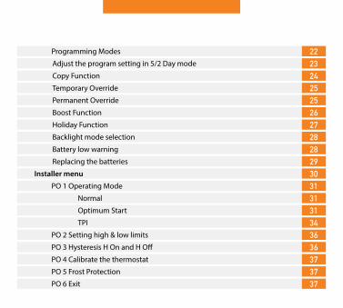
RFRP-OT Room Thermostat (Continued)
Installer menu - OpenTherm
38 PO 6 Setting DHW temperature
3940 PO 8 DHOP
40
43
PO 9 Set OpenTherm® parameters
Controlling an OpenTherm Boiler with multiple CombiPack 4-OT42
46
50
52
RF1A Wireless Receiver
Operating Instructions
49
51
Table of contents (Continued)
PO 7 OpenTherm® Information
Exit
System Architecture
LED Description
To disconnect the RFRP-OT thermostat to an RF1A-OT receiver
Button / LED Description
To connect the RFRP-OT thermostat to an RF1A-OT receiver
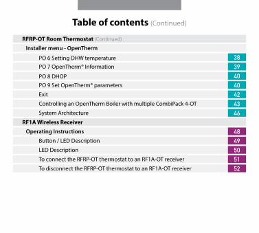
5
RFRP-OT Room ThermostatInstallation Instructions
6 RFRP-OT Room Thermostat CombiPack4
RFRP-OT Room Thermostat Factory Default Settings
Temperature indicator: ˚CSwitching differential: 0.4˚CIn built frost protection: 5˚C - Not adjustableClock: 24 hoursKeypad lock: OffOperating mode: 5/2 day
Frost Protection 5˚C
Frost protection is built into this thermostat.It is pre fixed at 5°C and is not adjustable.It will only be activated when the thermostat is in the OFF mode and the room temperature falls below 5°C.

7RFRP-OT Room Thermostat CombiPack4
Specifications
Power supply: 2 x AA Alkaline BatteryPower consumption: 2 mWBattery replacement: Once a yearTemp. control range: 5 … 35˚CAmbient temperature: 0 … 45˚CDimensions: 130 x 99 x 25mmTemperature sensor: NTC 100K Ohm @ 25˚CTemperature indication: ˚CSwitching differential: 0.4˚CFrost protection: Only operational in Off modePollution degree: Pollution degree 2
8 RFRP-OT Room Thermostat CombiPack4
When the thermostat is in the AUTO mode, it will operate according to the times and temperatures that have been programmed. The user can select from 6 different programs per day - each with a time and a temperature.
There is no OFF time, only a higher and a lower temperature.
If the user wants the thermostat to be OFF at a certain time, set the temperature for this time to be low. The thermostat will turn ON if the room temperature is lower than the setpoint for the current period.
Example: If P1 is set to be 21˚C at 6am, and if P2 is set to be 10˚C at 8am, the thermostat will look for the temperature to be 21˚C between 6am and 8am.
How your programmable thermostat works
9RFRP-OT Room Thermostat CombiPack4
Mounting & Installation
Caution! � Installation and connection should only be carried out by a qualified person.
� Only qualified electricians or authorised service staff are permitted to open the thermostat.
� If the thermostat is used in a way not specified by the manufacturer, its safety may be impaired.
� Prior to setting the thermostat, it is necessary to complete all required settings described in the section.
This thermostat can be mounted in the following ways:1) Directly mounted on wall 2) Free standing - Stand Included
10 RFRP-OT Room Thermostat CombiPack4
1) The mounting height should be 1.5 metres above the floor level.
2) The thermostat should be wall mounted in the room where the heating is to be controlled.
The place of installation should be chosen so that the sensor can measure the room temperature as accurately as possible.
Choose the mounting location to prevent direct exposure to sunlight or other heating / cooling sources when mounted.
3) Fix the mounting plate directly to the wall with the screws provided.
4) Attach the thermostat to the mounting plate.
5) Lower the flap at the front of the thermostat. There is a battery compartment located below the buttons. Apply downward pressure to remove the cover.
6) Insert the 2 x AA batteries and the thermostat will turn on. Close the battery compartment.
Mounting & Installation (Continued)

11RFRP-OT Room Thermostat CombiPack4
1 2
131
100
3 4
5 6

12 RF1A-OT Wireless Receiver CombiPack4
RF1A Wireless ReceiverInstallation Instructions

13RF1A-OT Wireless Receiver CombiPack4
Internal wiring diagram for RF1A-OT
Specifications & Wiring
Power supply: 200 - 240Vac 50-60HzContact rating: 250 Vac 10(3)AAmbient temperature: 0 … 45˚CAutomatic action: Type 1.C.QAppliance classes: Class II appliance Pollution degree: Pollution degree2IP Rating: IP20Rated Impulse Voltage: Resistance to voltage surge 2500V as per EN 60730
OFFON
3 2 1 L N
L
MAINS SUPPLY
NCOM
O T
O T
* If mains voltage output is required, terminals L & 2 must be electrically linked.
Important: Do not connect Mains Voltage to OpenTherm® terminals.

14 RF1A-OT Wireless Receiver CombiPack4
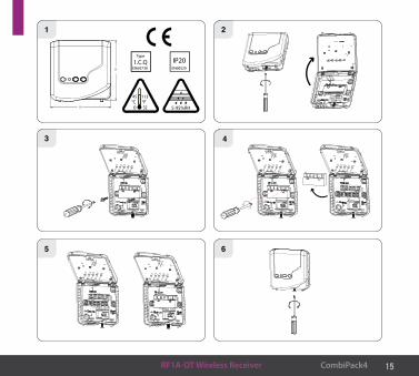
1) The RF1A-OT receiver should be wall mounted in an area within 20 metres distance of the wireless thermostat. It is important that the receiver is mounted more than 1 metre away from metal objects as this will affect communication with the thermostat.
The receiver should be installed at least 1metre from any electronic devices such as radio, TV, microwave or wireless network adaptor.
2) Slacken the fastening screw on the bottom of the receiver with a philips screwdriver. The receiver is hinged and can be opened 180 degrees.
3) Screw the receiver to the wall with the screws provided.
4) Remove the protective cover on the terminal block.
5) Insert wires into therminal block in accordance with the wiring diagram.
6) Close the cover and tighten the fastening screw.
Mounting & Installation
15RF1A-OT Wireless Receiver CombiPack4
1 2
84
86
3 4
5 6

16 RFRP-OT Room Thermostat CombiPack4
RFRP-OT Room ThermostatOperating Instructions

17RFRP-OT Room Thermostat CombiPack4
LCD Symbol Description
Operating mode
Current program
Day / Month
Day of the weekTemperature
Battery low symbol
Wireless symbol
Heating on symbol
Keypad lock symbol
Current Time(Boost to time)

18 RFRP-OT Room Thermostat CombiPack4
Button Description
Automatic mode Set Date / Time Set point increase
Manual mode Holiday mode Set point decrease
Off mode Copy function Copy function
Copy functionProgram mode Boost mode
AUTO TIME
MAN HOL
OFF COPY OK
PROG BOOST
Manualmode
O� mode
Program mode Set Date/ Time
Holiday mode
Copy function
Boost mode
Automatic mode(Back)
OK con�rm button
Set point increase
Set point decrease
Reset button
Wireless connect button

19RFRP-OT Room Thermostat CombiPack4
RFRP-OT Room Thermostat Resetting the thermostat
Keypad lock and unlock OFF
To lock the keypad, press and hold the and buttons for 10 seconds.
will appear on the screen. The keypad is now locked.
To unlock the keypad, press and hold the and buttons for 10 seconds.
will disappear from the screen. The keypad is now unlocked.
Press the button on the side of the thermostat.
‘rst no’ will appear on the screen.
Press the button.
‘rst yes’ will appear on the screen.
Press the OK button to reset the thermostat.

20 RFRP-OT Room Thermostat CombiPack4
Press the TIME button once, the year will begin flashing.
Press the or buttons to adjust the year. Press OK .
Press the or buttons to adjust the month. Press OK .
Press the or buttons to adjust the day. Press OK .
Press the or buttons to adjust the hour. Press OK .
Press the or buttons to adjust the minute. Press OK .
Press the or buttons to adjust from 5/2d to 7d or 24h mode.
Press the or buttons to turn DST (Day Light Saving time) On or Off.
Press the AUTO button or wait 5 seconds and the thermostat will return to normal operation.
Setting the date, time and programming mode
21RFRP-OT Room Thermostat CombiPack4
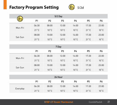
Factory Program Setting 5/2d
5/2 Day
P1 P2 P3 P4 P5 P6
Mon-Fri06:30 08:00 12:00 14:00 17:30 22:00
21˚C 10˚C 10˚C 10˚C 21˚C 10˚C
Sat-Sun08:00 10:00 12:00 14:00 17:30 23:00
21˚C 10˚C 10˚C 10˚C 21˚C 10˚C
7 Day
P1 P2 P3 P4 P5 P6
Mon-Fri06:30 08:00 12:00 14:00 17:30 22:00
21˚C 10˚C 10˚C 10˚C 21˚C 10˚C
Sat-Sun08:00 10:00 12:00 14:00 17:30 23:00
21˚C 10˚C 10˚C 10˚C 21˚C 10˚C
24 Hour
P1 P2 P3 P4 P5 P6
Everyday06:30 08:00 12:00 14:00 17:30 22:00
21˚C 10˚C 10˚C 10˚C 21˚C 10˚C
22 RFRP-OT Room Thermostat CombiPack4
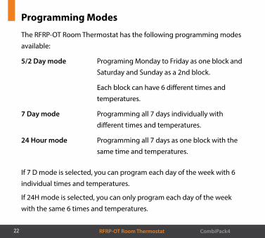
The RFRP-OT Room Thermostat has the following programming modes available:
5/2 Day mode Programing Monday to Friday as one block and Saturday and Sunday as a 2nd block.
Each block can have 6 different times and temperatures.
7 Day mode Programming all 7 days individually with different times and temperatures.
24 Hour mode Programming all 7 days as one block with the same time and temperatures.
Programming Modes
If 7 D mode is selected, you can program each day of the week with 6 individual times and temperatures.
If 24H mode is selected, you can only program each day of the week with the same 6 times and temperatures.
23RFRP-OT Room Thermostat CombiPack4
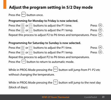
Press the PROG button once.
Programming for Monday to Friday is now selected.Press the or buttons to adjust the P1 time. Press OK .Press the or buttons to adjust the P1 temp. Press OK .Repeat this process to adjust P2 to P6 times and temperatures. Press OK .
Programming for Saturday to Sunday is now selected.Press the or buttons to adjust the P1 time. Press OK .Press the or buttons to adjust the P1 temp. Press OK . Repeat this process to adjust P2 to P6 times and temperatures. Press the AUTO button to return to automatic mode.
While in PROG Mode pressing the PROG button will jump from P1-P2 etc without changing the temperature.
While in PROG Mode pressing the TIME button will jump to the next day (block of days).
Adjust the program setting in 5/2 Day mode
24 RFRP-OT Room Thermostat CombiPack4
Copy Function
Copy function may only be used if the thermostat is in the 7d mode.
Set the times and temperatures for the day that you wish to copy from in programming mode.
When still on the day press the COPY button.
The day of the week that you have selected will be shown with ‘COPY’ below it.
The next day will begin to flash on the top of the screen.
Press the button to copy the times and temperatures to that day.
Press the button to skip a day.
You can copy to multiple days using the button.
Press the OK button when copying has been completed.

25RFRP-OT Room Thermostat CombiPack4
When in AUTO mode, press the or buttons to adjust the temperature setpoint. ‘OvEr’ will appear on the screen.
Press OK or after 5 seconds the thermostat will operate in this temporary override, until the next switching time.
To cancel temporary override, press the OFF buttton and then press the AUTO button to return to the automatic mode.
Press the MAN button to enter the manual mode (Permanent Override), ‘MAN’ will appear on the screen. Press the or buttons to adjust the temperature setpoint.Press OK or after 5 seconds the thermostat will operate in this permanent override.To cancel permanent override, press the OFF buttton and then press the AUTO button to return to the automatic mode.
Temporary Override
Permanent Override
26 RFRP-OT Room Thermostat CombiPack4
The thermostat can be boosted to a specific temperature for 1, 2 or 3 hours while the thermostat is operating in all modes except for holiday mode.
Press the BOOST button 1, 2 or 3 times, the time that the boost will be activated to will flash on the screen.
If you do not press any other button the boost will activate to the temperature displayed on the screen after 5 seconds.
If you press the OK button the temperature will now flash. You can edit the temperature if you press the or buttons.
Press the OK button or wait for 5 seconds for the boost to activate.
‘BOOST TO’ will now be displayed on the screen with the time that it is activated to displayed above this text.
Press the BOOST button again to deactivate the boost.
Boost Function

27RFRP-OT Room Thermostat CombiPack4
This will switch your heating system off between the start and end times you select .
Press the HOL button, ‘HOLIDAY FROM’ will appear on screen.
Press the or buttons to adjust the year. Press OK .
Press the or buttons to adjust the month. Press OK .
Press the or buttons to adjust the day. Press OK .
Press the or buttons to adjust the hour. Press OK .
‘HOLIDAY TO’ will appear on screen.
Press the or buttons to adjust the day. Press OK .
Press the or buttons to adjust the month. Press OK .
Press the or buttons to adjust the year. Press OK .
Press the or buttons to adjust the hour. Press OK .
The thermostat will now return to the mode it was in before the Holiday settings were entered. To cancel Holiday mode, press the HOL button.
Holiday Function
28 RFRP-OT Room Thermostat CombiPack4
Backlight mode selection AUTO
Battery low warning
There are two settings for selection. The factory default setting is AUTO.
OFF The backlight is permanently OFF.
AUTO On pressing any button the backlight stays on for 5 seconds.
To adjust the backlight setting, lower the cover on the front of the unit.
Press the OK button for 5 seconds.
Press either the or buttons to select the OFF or AUTO mode.
Press the OK button.
When the batteries are almost empty, the symbol will appear on the screen.
The batteries must now be replaced or the unit will shut down.

29RFRP-OT Room Thermostat CombiPack4
Replacing the batteries
Lower the flap at the front of the thermostat.
There is a battery compartment located below the buttons.
Apply downward pressure to remove the cover.
Insert the 2 x AA batteries and the thermostat will turn on.
Close the battery compartment.

30 RFRP-OT Room Thermostat CombiPack4
Installer menu
To access the installer menu, you must hold Prog and OK for 5 seconds.
When in the installer menu, press , and OK to navigate and select. Use AUTO , MAN or OFF to go back a step.
P0 1: Mode (Normal / Optimum Start / TPI)P0 2: Hi Lo (limiting the thermostat)P0 3: Hysteresis (differential)P0 4: CalibrationP0 5: Frost ProtectionP0 6: Exit
Installer menu OpenTherm® Instructions
P0 6: Setting DHW temperatureP0 7: OpenTherm® InformationP0 8: DHOPP0 9: Set OpenTherm® ParametersExit

31RFRP-OT Room Thermostat CombiPack4
Nor (Normal Mode)
When the thermostat is in Normal mode, the thermostat will try to reach the target temperature after the program changes.
Example: Program 1 on the thermostat is 21°C for 06:30am and the room temperature is 18°C. The thermostat will start the heating at 06:30am and the room temperature will start to increase then.
PO 1 Operating Mode (Normal / Optimum Start / TPI)
OS (Optimum Start Mode) Boiler Plus
When the thermostat is in Optimum Start mode, the thermostat will try to reach the target temperature by the start time of the next switching time. This is done by setting the Ti (time interval) on the thermostat in this menu to 10, 15, 20, 25 or 30. This will allow the thermostat 10, 15, 20, 25 or 30 minutes to increase the room temperature by 1°C.
Ti can be set when OS is selected in the installer menu. 20˚C
32 RFRP-OT Room Thermostat CombiPack4
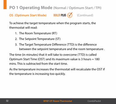
OS (Optimum Start Mode) Boiler Plus (Continued)
PO 1 Operating Mode (Normal / Optimum Start / TPI)
To achieve the target temperature when the program starts, the thermostat will read:
1. The Room Temperature (RT)
2. The Setpoint Temperature (ST)
3. The Target Temperature Difference (TTD) is the difference between the setpoint temperature and the room temperature .
The time (in minutes) that it will take to overcome (TTD) is called Optimum Start Time (OST) and its maximum value is 3 hours = 180 mins. This is subtracted from the start time.
As the temperature increases the thermostat will recalculate the OST if the temperature is increasing too quickly.

33RFRP-OT Room Thermostat CombiPack4
Example when Ti = 20
Program 1 on the thermostat is 21°C for 06:30am and the room temperature is 18°C. The thermostat will start the heating at 05:30am to reach 21°C for 06:30am @ Ti=20.
Example when Ti = 10
Program 1 on the thermostat is 21°C for 06:30am and the room temperature is 18°C. The thermostat will start the heating at 06:00am to reach 21°C for 06:30am @ Ti=10.
0
20
40
60
80
100
120
140
160
180
Opt
imum
Sta
rt T
ime
(Min
s)
Target Temperature Di�erence ˚CTTD
89 7 6 5 4 3 2 1
Optimum Start Control Graph with Ti = 200
15
30
45
60
75
90
105
120
135
Opt
imum
Sta
rt T
ime
(Min
s)
Target Temperature Di�erence ˚CTTD
89 7 6 5 4 3 2 1
Optimum Start Control Graph with Ti = 15
0
10
20
30
40
50
60
70
80
90
Opt
imum
Sta
rt T
ime
(Min
s)
Target Temperature Di�erence ˚CTTD
89 7 6 5 4 3 2 1
Optimum Start Control Graph with Ti = 10

34 RFRP-OT Room Thermostat CombiPack4
PO 1 Operating Mode (Normal / Optimum Start / TPI)
TPI (Time Proportional & Integral Mode)
When the thermostat is in TPI mode and the temperature is rising in the zone and falls into the Proportional Bandwidth section, TPI will start to affect the thermostats operation. The thermostat will turn on and off as it gains heat so that it doesn’t overshoot the setpoint by too much. It will also turn on if the temperature is falling so it doesn’t undershoot the setpoint which will leave the user with a more comfortable level of heat.
There are 2 settings that will affect the thermostats operation:
1. CYC - No. of Heating Cycles per Hour: 6 Cycles
This value will decide how often the thermostat will cycle the heating on and off when trying to achieve the setpoint temperature. You can select 2/3/6 or 12.
2. Pb - Proportional Bandwidth: 2˚C
This value refers to the temperature below the setpoint at which the thermostat will start to operate in TPI Control. You can set this temperature from 1.5˚C to 3.0˚C in 0.1˚C increments.
35RFRP-OT Room Thermostat CombiPack4
22˚C
21˚C
20˚C
19˚C
18˚C
17˚C
Temp
Time Minutes
Heating On Heating O�
Setpoint Temperature
Proportional Bandwidth
200 40 60 80 100
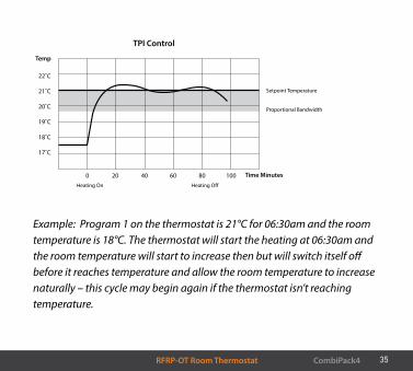
TPI Control
Example: Program 1 on the thermostat is 21°C for 06:30am and the room temperature is 18°C. The thermostat will start the heating at 06:30am and the room temperature will start to increase then but will switch itself off before it reaches temperature and allow the room temperature to increase naturally – this cycle may begin again if the thermostat isn’t reaching temperature.

36 RFRP-OT Room Thermostat CombiPack4
This menu allows the installer to change the min. and max. temperature range that the thermostat can be set at.
PO 2 Setting high & low limits Hi 35˚C and Lo 5˚C
This menu allows the installer to change the switching differential of the thermostat when the temperature is rising and falling.
HOn is the fall in temperature – Default – 0.4°C. This will allow a fall of 0.4°C from the setpoint before the thermostat turns on again.
HOFF is the rise in temperature – Default – 0.0°C. This will allow the temperature to rise 0°C above its setpoint.
PO 3 Hysteresis HOn and HOFF
37RFRP-OT Room Thermostat CombiPack4
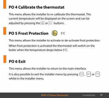
PO 4 Calibrate the thermostat
This menu allows the installer to re-calibrate the thermostat. The current temperature will be displayed on the screen and can be adjusted by pressing the or buttons .
This menu allows the installer to activate or de-activate frost protection.
When frost protection is activated the thermostat will switch on the boiler when the temperature drops below 5˚C.
This menu allows the installer to return to the main interface.
It is also possible to exit the installer menu by pressing AUTO , MAN or OFF
whilst in the installer menu.
PO 5 Frost Protection
PO 6 Exit
5˚C
38 RFRP-OT OpenTherm® Instructions
This menu allows the installer to change the DHW temperature of the boiler. The temperature can be set in 0.5°C increments by pressing the
or buttons.
Press the OK button to select the desired temperature.
This menu is only available when the thermostat is connected to OpenTherm® and DHOP is ON (P08 OT installer menu).
PO 6 Setting DHW temperature
39RFRP-OT OpenTherm® Instructions
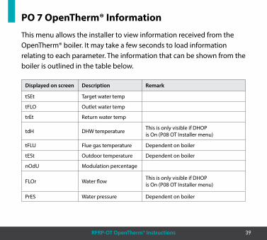
This menu allows the installer to view information received from the OpenTherm® boiler. It may take a few seconds to load information relating to each parameter. The information that can be shown from the boiler is outlined in the table below.
PO 7 OpenTherm® Information
Displayed on screen Description Remark
tSEt Target water temp
tFLO Outlet water temp
trEt Return water temp
tdH DHW temperature This is only visible if DHOPis On (P08 OT Installer menu)
tFLU Flue gas temperature Dependent on boiler
tESt Outdoor temperature Dependent on boiler
nOdU Modulation percentage
FLOr Water flow This is only visible if DHOPis On (P08 OT Installer menu)
PrES Water pressure Dependent on boiler
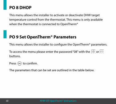
40 RFRP-OT OpenTherm® Instructions
This menu allows the installer to activate or deactivate DHW target temperature control from the thermostat. This menu is only available when the thermostat is connected to OpenTherm®
This menu allows the installer to configure the OpenTherm® parameters.
To access the menu please enter the password “08” with the or buttons.
Press OK to confirm.
The parameters that can be set are outlined in the table below.
PO 8 DHOP
PO 9 Set OpenTherm® Parameters

41RFRP-OT OpenTherm® Instructions
Param Description Range Default
HHCH t-1 Maximum set point heating 45 - 85˚C 85˚C
LLCH t-2 Minimum set point heating 10 - HHCH˚C 45˚C
CLI t-3
This allows user to select different climatic curves for weather compensation. This only applies to Boilers with an outside sensor connected.
0.2 - 3.0 1.2
InFL t-4 Influence of room sensor on modulation of the boiler. Recommended value is 10. 0 - 20 10
HHbO t-5
This is the target setpoint for your CH flow temperature.Note: this value must be within the range of HHCH and LLCH.
HHCH Max >=ID57>=LLCH Min
85˚C
Exit Press OK button to turn back to main interface.

42 RFRP-OT OpenTherm® Instructions
PO 9 Set OpenTherm® parameters
Climatic Curve
1003 2.5
2
1.51.2
1
0.80.60.40.2
80
60
40
2020 16 12 8 4 0 -4 -8 -12 -16
This menu allows the installer to return to the main interface.
It is also possible to exit the installer menu by pressing AUTO, MAN or OFF whilst in the installer menu.
Exit
43RFRP-OT OpenTherm® Instructions
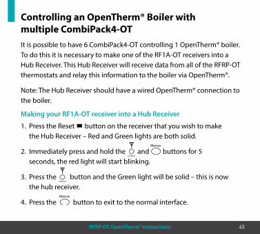
It is possible to have 6 CombiPack4-OT controlling 1 OpenTherm® boiler. To do this it is necessary to make one of the RF1A-OT receivers into a Hub Receiver. This Hub Receiver will receive data from all of the RFRP-OT thermostats and relay this information to the boiler via OpenTherm®.
Note: The Hub Receiver should have a wired OpenTherm® connection to the boiler.
1. Press the Reset button on the receiver that you wish to make the Hub Receiver – Red and Green lights are both solid.
2. Immediately press and hold the Connect
and buttons for 5 seconds, the red light will start blinking.
3. Press the Connect
button and the Green light will be solid – this is now the hub receiver.
4. Press the button to exit to the normal interface.
Controlling an OpenTherm® Boiler with multiple CombiPack4-OT
Making your RF1A-OT receiver into a Hub Receiver

44 RFRP-OT OpenTherm® Instructions
Controlling an OpenTherm® Boiler with multiple CombiPack4-OT (Continued)
Identifying if a receiver is a Hub Receiver
Pairing the RF1A-OT receivers together
1. Press the Connect
button.
2. The Hub receiver will flash Green and Red.
3. The Normal receiver will just flash Red.
4. To exit to main interface press the button.
Once all units have been paired, allow time for the receivers to begin to communicate and receive OpenTherm® information from the boiler. This may take approximately 2 – 5 minutes.
1. Press the Connect
button on the Hub receiver. Red and Green lights will begin to flash.
2. Press the Connect
button on the next receiver to be paired. The Red light will flash 3 times and then stop.
3. Repeat this process to pair more, up to a maximum of 6 receivers.
45RFRP-OT OpenTherm® Instructions
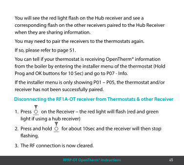
Disconnecting the RF1A-OT receiver from Thermostats & other Receiver
1. Press Connect
on the Receiver – the red light will flash (red and green light if using a hub receiver)
2. Press and hold Connect
for about 10sec and the receiver will then stop flashing.
3. The RF connection is now cleared.
You will see the red light flash on the Hub receiver and see a corresponding flash on the other receivers paired to the Hub Receiver when they are sharing information.
You may need to pair the receivers to the thermostats again.
If so, please refer to page 51.
You can tell if your thermostat is receiving OpenTherm® information from the boiler by entering the installer menu of the thermostat (Hold Prog and OK buttons for 10 Sec) and go to P07 - Info.
If the installer menu is only showing P01 – P05, the thermostat and/or receiver has not been successfully paired.

46 RFRP-OT OpenTherm® Instructions
System architecture
Example A 1 no. Thermostat controlling OT Boiler
Example B 3 no. Thermostats controlling OT Boiler >>
RFRP-OT Thermostat RF1A-OT Receiver OpenTherm® Boiler
Note: A maximum of 6 thermostats can be used in the system.
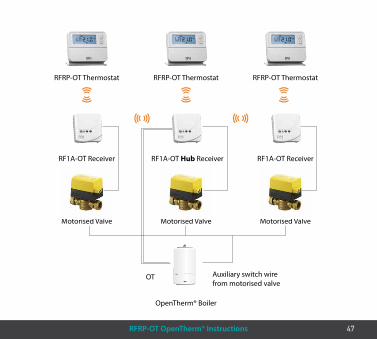
47RFRP-OT OpenTherm® Instructions
RFRP-OT Thermostat
Motorised Valve Motorised Valve Motorised Valve
RF1A-OT Receiver
OpenTherm® Boiler
RFRP-OT Thermostat
RF1A-OT Hub Receiver
RFRP-OT Thermostat
RF1A-OT Receiver
OT Auxiliary switch wire from motorised valve

48 RF1A-OT Wireless Receiver CombiPack4
RF1A Wireless ReceiverOperating Instructions
49RF1A-OT Wireless Receiver CombiPack4
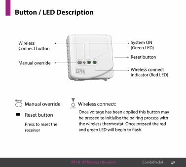
Button / LED Description
System ON (Green LED)
Manual override
WirelessConnect button
Wireless connectindicator (Red LED)
Reset button
Connect
Wireless connect: Once voltage has been applied this button may be pressed to initialise the pairing process with the wireless thermostat. Once pressed the red and green LED will begin to flash.
Manual override
Reset button
Press to reset the receiver
50 RF1A-OT Wireless Receiver CombiPack4
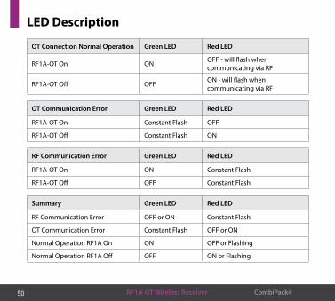
LED Description
OT Connection Normal Operation Green LED Red LED
RF1A-OT On ON OFF - will flash when communicating via RF
RF1A-OT Off OFF ON - will flash when communicating via RF
OT Communication Error Green LED Red LED
RF1A-OT On Constant Flash OFF
RF1A-OT Off Constant Flash ON
RF Communication Error Green LED Red LED
RF1A-OT On ON Constant Flash
RF1A-OT Off OFF Constant Flash
Summary Green LED Red LED
RF Communication Error OFF or ON Constant Flash
OT Communication Error Constant Flash OFF or ON
Normal Operation RF1A On ON OFF or Flashing
Normal Operation RF1A Off OFF ON or Flashing
51CombiPack4
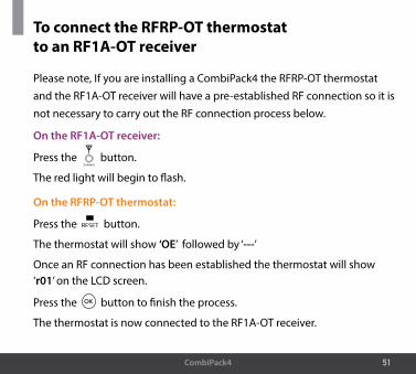
Please note, If you are installing a CombiPack4 the RFRP-OT thermostat and the RF1A-OT receiver will have a pre-established RF connection so it is not necessary to carry out the RF connection process below.
To connect the RFRP-OT thermostat to an RF1A-OT receiver
On the RF1A-OT receiver:
Press the Connect
button.
The red light will begin to flash.
On the RFRP-OT thermostat:
Press the button.
The thermostat will show ‘OE’ followed by ‘---’
Once an RF connection has been established the thermostat will show ‘r01’ on the LCD screen.
Press the OK button to finish the process.
The thermostat is now connected to the RF1A-OT receiver.

52 CombiPack4
This can be done from either the thermostat or the receiver.
To disconnect the RFRP-OT thermostat from an RF1A-OT receiver
On the RFRP-OT thermostat:
Press the button. The thermostat will begin to search through the RF channels.
Press and hold the COPY button for 10 seconds. ‘Adr’ will appear on the screen of the thermostat.
Press the OK button twice to complete the unpairing process. The thermostat RFRP-OT is now disconnected from the receiver RF1A-OT.
On the RF1A thermostat:
Press the Connect
button, the red light will flash.
Red & green lights if using as a hub receiver.
Press and hold connect for about 10 seconds, the receiver will then stop flashing.
The RF connection is now cleared.

Notes

Notes

Notes

EPH Controls IE
EPH Controls UK
© 2
019
EPH
Con
trol
s Lt
d.
[email protected] T +44 1933 626 396F +44 1933 626 218
2019
1205
_Com
biP
ack4
_Ins
trua
ctio
n
[email protected] +353 21 434 6238F +353 21 454 5890
Related Documents