Abstract— The angular Vestibulo-Ocular and Opto-Kinetic Reflexes (OKR and aVOR) combine to provide compensation for head rotations in space to help maintain a steady image on the retina. We previously implemented an artificial angular vestibulo-ocular reflex with a fully articulated binocular control system in a quadrupedal robot head. In this paper, we describe the implementation of artificial optokinetic and linear vestibular ocular reflexes (OKR and lVOR) that use inputs from an artificial vestibular sensor and a binocular camera system to compensate for linear movements of the head and visual motion to stabilize images on the cameras. The object tracking algorithm was able to fixate a steady object in the camera’s field of view during linear perturbations of the robot’s head in space at low frequencies of movement (0.2-0.6 Hz), simulating the linear VOR. We implemented an algorithm that combines the linear VOR and OKR model and computes changes in relative pose of the camera with respect to the object being tracked. The system provides compensatory angular movements of the Ocular Servo Module (OSM) to stabilize images as the robot is moved laterally. I. INTRODUCTION RIMATES have been extensively studied for their ability to stabilize images on the retina during locomotion with compensatory vestibulo-ocular and opto-kinetic reflexes (VOR and OKR) [1-5]. Similar compensatory systems have been implemented in robots that are capable of stabilizing images using artificial VOR and OKR systems [6, 7]. Also, the vestibulo-collic reflex was tested on quadrupedal robots that helped stabilize the head motors using inertial sensor inputs during locomotion [8]. There are other active vision Manuscript received February 22, 2008. This work was supported in part by the U.S. Army Research Office under grant W911NF-05-1-0011, and the U.S. National Science Foundation under grants CNS-0551598, CNS- 0619577 and IIS-0644127. Igor Labutov is with the Dept. of Computer Engineering, The City College of New York, The City University of New York (CUNY), 138 th street and Convent Avenue, New York, NY 10031 (email: [email protected] ) Ravi Kaushik and Marek Marcinkiewicz are with the Dept. of Computer Science, The Graduate Center, CUNY, 365, Fifth Avenue, New York NY 10016 (email: [email protected] , [email protected] ) Jizhong Xiao is with the Dept of Electrical Engineering, CUNY City College and CUNY Graduate Center, 138 th st and Convent Avenue, New York, NY 10031. (email: [email protected] ) Simon Parsons is with the Dept. of Computer and Information Science, CUNY Brooklyn College and CUNY Graduate Center, 2900 Bedford Avenue, Brooklyn, NY 11210 (email: [email protected] ) *Theodore Raphan is with the Dept. of Computer and Information Science, CUNY Brooklyn College and CUNY Graduate Center, 2900 Bedford Avenue, Brooklyn, NY 11210 (Corresponding Author email: [email protected] Ph: (718)-376-0503 Fax: (718)-951-4489) systems shown in [9, 10] that implement interactive vision system that controls the camera to fixate objects. When there is a head movement with a fixed camera system, displacement of objects in the image field can be measured and represented as Euler angles using the perspective camera model. Velocities of these angular displacements can then be used as input the opto-kinetic Reflex to generate compensatory movements to camera motors that form a Fick Gimbal system. The artificial lVOR system takes instantaneous linear acceleration inputs from an inertial sensor and compensates for translational movements of the head. In our work, we extended the previous implementations of these angular reflexes to stabilize the images during lateral movements of the head. The goal was to study the Humanoid head with two reflexes linear VOR and OKR functioning as one compensatory system that provides stability of images during linear movement. The robot head was fit with actuators that can be positioned precisely with a fully articulated 9 Degree Of Freedom (DOF) system from the neck-up. The neck has 3DOF and each Ocular Servo Module has 3DOF with three motors mounted orthogonal to one another, similar to the function of the neck and eye muscles. We refer to this as OSM [11], which provides the algorithm for the compensatory angular VOR that compensates for angular rotations of the head. Each of the subsystems serves different purposes. The linear VOR provides fast response with small latency at higher frequencies. The simulated VOR system does not respond to any form of spatial position of the cameras with respect to the surrounding environment and there is a bias after certain time is elapsed. The simulated OKR system provides the information in the form of visual cues tracking an object and resetting the bias term. The OKR system works well at only lower frequency due to the nature of the sensor and the computation involved, similar to the OKR system in primates [5]. Our robot system is also unique in that the algorithms take into account the non-commutative property of 3-D rotations. We computed the appropriate compensatory Euler angles in yaw, pitch and roll to the actuators to be consistent with these 3-D rotations and be able to compensate over a wide range of frequencies of motion of the head. The humanoid robot was then tested for aVOR responses in roll at various frequencies. It was also oscillated linearly in two dimensions in horizontal plane. This latter motion was used to study the compensatory response of linear VOR Combining Linear Vestibulo-Ocular and Opto-Kinetic Reflex in a Humanoid Robot Igor Labutov, Ravi Kaushik, Marek Marcinkiewicz, Jizhong Xiao, Simon Parsons, Theodore Raphan* P

Welcome message from author
This document is posted to help you gain knowledge. Please leave a comment to let me know what you think about it! Share it to your friends and learn new things together.
Transcript
Abstract— The angular Vestibulo-Ocular and Opto-Kinetic
Reflexes (OKR and aVOR) combine to provide compensation for head rotations in space to help maintain a steady image on the retina. We previously implemented an artificial angular vestibulo-ocular reflex with a fully articulated binocular control system in a quadrupedal robot head. In this paper, we describe the implementation of artificial optokinetic and linear vestibular ocular reflexes (OKR and lVOR) that use inputs from an artificial vestibular sensor and a binocular camera system to compensate for linear movements of the head and visual motion to stabilize images on the cameras. The object tracking algorithm was able to fixate a steady object in the camera’s field of view during linear perturbations of the robot’s head in space at low frequencies of movement (0.2-0.6 Hz), simulating the linear VOR. We implemented an algorithm that combines the linear VOR and OKR model and computes changes in relative pose of the camera with respect to the object being tracked. The system provides compensatory angular movements of the Ocular Servo Module (OSM) to stabilize images as the robot is moved laterally.
I. INTRODUCTION
RIMATES have been extensively studied for their ability to stabilize images on the retina during locomotion with
compensatory vestibulo-ocular and opto-kinetic reflexes (VOR and OKR) [1-5]. Similar compensatory systems have been implemented in robots that are capable of stabilizing images using artificial VOR and OKR systems [6, 7]. Also, the vestibulo-collic reflex was tested on quadrupedal robots that helped stabilize the head motors using inertial sensor inputs during locomotion [8]. There are other active vision
Manuscript received February 22, 2008. This work was supported in part
by the U.S. Army Research Office under grant W911NF-05-1-0011, and the U.S. National Science Foundation under grants CNS-0551598, CNS-0619577 and IIS-0644127.
Igor Labutov is with the Dept. of Computer Engineering, The City College of New York, The City University of New York (CUNY), 138th street and Convent Avenue, New York, NY 10031 (email: [email protected])
Ravi Kaushik and Marek Marcinkiewicz are with the Dept. of Computer Science, The Graduate Center, CUNY, 365, Fifth Avenue, New York NY 10016 (email: [email protected], [email protected])
Jizhong Xiao is with the Dept of Electrical Engineering, CUNY City College and CUNY Graduate Center, 138th st and Convent Avenue, New York, NY 10031. (email: [email protected])
Simon Parsons is with the Dept. of Computer and Information Science, CUNY Brooklyn College and CUNY Graduate Center, 2900 Bedford Avenue, Brooklyn, NY 11210 (email: [email protected])
*Theodore Raphan is with the Dept. of Computer and Information Science, CUNY Brooklyn College and CUNY Graduate Center, 2900 Bedford Avenue, Brooklyn, NY 11210 (Corresponding Author email: [email protected] Ph: (718)-376-0503 Fax: (718)-951-4489)
systems shown in [9, 10] that implement interactive vision system that controls the camera to fixate objects. When there is a head movement with a fixed camera system, displacement of objects in the image field can be measured and represented as Euler angles using the perspective camera model. Velocities of these angular displacements can then be used as input the opto-kinetic Reflex to generate compensatory movements to camera motors that form a Fick Gimbal system. The artificial lVOR system takes instantaneous linear acceleration inputs from an inertial sensor and compensates for translational movements of the head. In our work, we extended the previous implementations of these angular reflexes to stabilize the images during lateral movements of the head. The goal was to study the Humanoid head with two reflexes linear VOR and OKR functioning as one compensatory system that provides stability of images during linear movement. The robot head was fit with actuators that can be positioned precisely with a fully articulated 9 Degree Of Freedom (DOF) system from the neck-up. The neck has 3DOF and each Ocular Servo Module has 3DOF with three motors mounted orthogonal to one another, similar to the function of the neck and eye muscles. We refer to this as OSM [11], which provides the algorithm for the compensatory angular VOR that compensates for angular rotations of the head. Each of the subsystems serves different purposes. The linear VOR provides fast response with small latency at higher frequencies. The simulated VOR system does not respond to any form of spatial position of the cameras with respect to the surrounding environment and there is a bias after certain time is elapsed. The simulated OKR system provides the information in the form of visual cues tracking an object and resetting the bias term. The OKR system works well at only lower frequency due to the nature of the sensor and the computation involved, similar to the OKR system in primates [5]. Our robot system is also unique in that the algorithms take into account the non-commutative property of 3-D rotations. We computed the appropriate compensatory Euler angles in yaw, pitch and roll to the actuators to be consistent with these 3-D rotations and be able to compensate over a wide range of frequencies of motion of the head.
The humanoid robot was then tested for aVOR responses in roll at various frequencies. It was also oscillated linearly in two dimensions in horizontal plane. This latter motion was used to study the compensatory response of linear VOR
Combining Linear Vestibulo-Ocular and Opto-Kinetic Reflex in a Humanoid Robot
Igor Labutov, Ravi Kaushik, Marek Marcinkiewicz, Jizhong Xiao, Simon Parsons, Theodore Raphan*
P
and OKR system at various frequencies. When the platform oscillated at different frequencies causing the head to oscillate, the VOR and OKR systems responded uniquely based on their processing time and sensor frequency output and mimicked the response of primates.
A. Paper Organization
Section II briefly describes the Humanoid robot platform. Section III is a revision of the theory of angular VOR implementation partly used in the new proposed algorithm. It includes the transformation matrices that update the Euler angles fed into the Ocular Servo Module (OSM) to keep the image stable. Section IV describes the OKR and the vision tracking algorithm that compensates using vision cues from the camera as the input. Section V introduces the compensatory lVOR/OKR modeling and describes the algorithm that controls the system with inputs from vision sensors and inertial sensors and provides input to the intelligent actuators that are capable of responding to high frequencies.
II. ROBOT HEAD PLATFORM
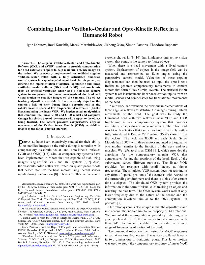
Fig.1. Humanoid Robot Head (9DOF) fitted with intelligent actuators that forms Pan/Tilt/Roll system at the Neck, Left and Right Eye.
The humanoid robot head has 9DOF built from intelligent actuators. The actuators in the head are Faulhaber® DC micromotors 1524E024SRIE-512+15/8 262:1 zero backlash gearhead providing 300mNm of torque. Each motor is controlled with the Faulhaber® DSP Controller MCDC3003. Each controller communicates with the host computer through RS232 protocol. With more than one controller on a single serial port, all serial ports leading from the controller are daisy chained onto a single serial port of the host computer.
III. VESTIBULO-OCULAR REFLEX
The compensatory angular VOR algorithm was implemented in a quadrupedal robot [11]. We present the algorithm in order to keep continuity with the theory. Also, we utilized these equations to determine the commanded rotations of the cameras due to linear acceleration and the optokinetic input.
The camera rotations can be given as a sequence of rotation matrices as follows:
!
Rxyz = Rx (") # Ry ($) # Rz (%) (1)
where
!
Rx (") =
1 0 0
0 cos" #sin"
0 sin" cos"
$
%
& & &
'
(
) ) )
Ry (*) =
cos* 0 sin*
0 1 0
#sin* 0 cos*
$
%
& & &
'
(
) ) )
Rz (+) =
cos+ #sin+ 0
sin+ cos+ 0
0 0 1
$
%
& & &
'
(
) ) )
(2)
Substituting Eqn. 2 into Eqn. 1, we obtain the rotation matrix for the eye relative to the head as:
!
Rcur
=
cos" # cos$ cos" # sin$ # sin% & sin" # cos% cos" # sin$ # cos% + sin" # sin%
sin" # cos$ sin" # sin$ # sin% + cos" # cos% sin" # sin$ # cos% & cos" # sin%
&sin$ cos$ # sin% cos$ # cos%
'
(
) ) )
*
+
, , ,
(3)
The incremental change in head rotation was obtained from the acceleration sensor as the angular velocity vector represented by ω, n rad/s. The incremental axis of the rotation of the head at any given time t is therefore given by
!
n
^
="
||" || (4)
where
!
n
^
is a unit vector in the direction of the incremental rotation. ΦInc is the incremental angle of rotation about the axis of rotation and is given by:
!
"Inc
=||# || $%t (5) where Δt is the time between the two sensor readings. The resulting incremental axis of rotation and incremental angle of rotation is fed into the Rodrigues formula. (An efficient method to compute rotations)
!
RInc
=
cos"+ n12 # (1$ cos") n1 # n2 # (1$ cos") $ n3 # sin" n1 # n3 # (1$ cos") + n2 # sin"
n2 # n1 # (1$ cos") + n3 # sin" cos"+ n22 # (1$ cos") n2 # n3(1$ cos") $ n1 # sin"
n3 # n1 # (1$ cos") $ n2 # sin" n3 # n2 # (1$ cos") + n1 # sin" cos"+ n32(1$ cos")
%
&
' ' '
(
)
* * *
(6)
Eqn. 6 provides the incremental rotational matrix
representing the change in angles of the head in 3 dimensions. The new position of the servomotors at any instant of time is obtained by determining the incremental changes for the Euler angles, each of which is associated with a particular motor. The incremental Euler angles are obtained from Eqn. (6) as:
!
"new
="old
+ tan#1 r23
r33
$new
= $old
+ sin#1r13
%new
= %old
+ tan#1 r12
r11
(7)
where the parameters r11, r12, r13, r23, r33 are the associated matrix elements for a particular head orientation in Eqn. (3).
Cameras (Artificial OKR Sensors) Inertial Sensor
(Artificial VOR)
Servo Controller and Motors
IV. OPTO-KINETIC RESPONSE (OKR)
A. Primate OKR
OKR is a visual reflex response system that takes input cues from images on the retina. The small movements of an object in focus in the image are processed as modeled in [1]. The resulting action stabilizes the image in the retina. There is a high latency in processing the OKR as compared to VOR. The main purpose of the OKR is to reset any bias error created by the linear VOR inherent with inertial sensors. Models of velocity-position integrator [12] have been developed known to process in 3D both the vestibular inputs (semicircular canals and otoliths) and visual inputs coupled together to interpret gravitational information relevant for determining spatial orientation. The application of the position-integrator is drawn from these models. Visual cues from the surrounding environment are multidimensional and processing all of them to know the retinal slip is difficult. We measured the performance of the stabilization by determining the retinal slip during visual surround movement relative to the robot.
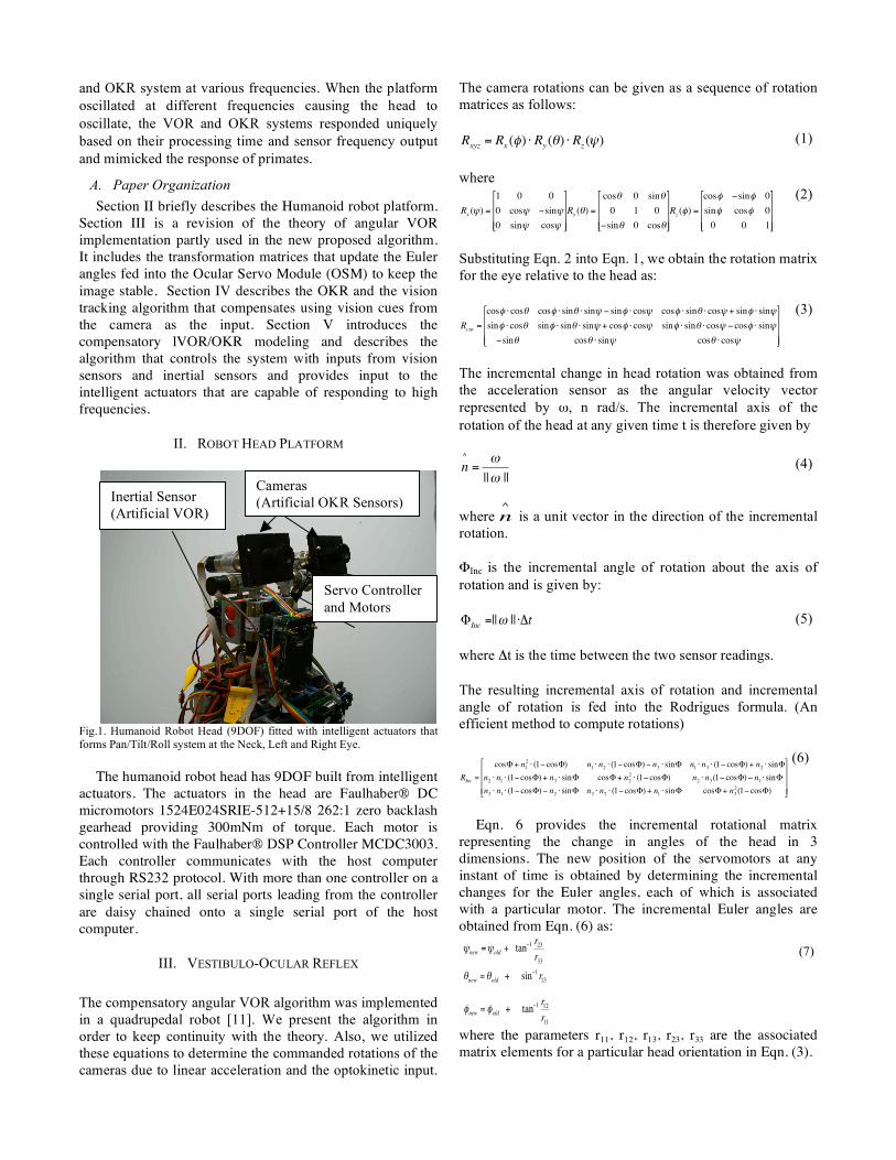
B. Modeling the OKR
Fig. 3 shows a perspective camera model that tracks object motion in 3D based on its 2D image coordinates. When the object moves in image space, instantaneous yaw, pitch and roll angles are computed in calculating pixel offset. This model computes (θ, ϕ, φ) in (X, Y, Z) axes respectively.
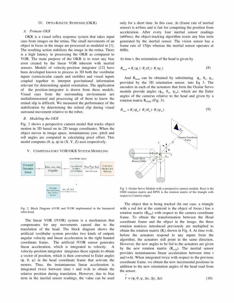
V. COMPENSATORY VOR/OKR SYSTEM MODELING
Fig. 2. Block Diagram aVOR and lVOR implemented in the humanoid robot head.
The linear VOR (lVOR) system is a mechanism that compensates for any movements caused due to the translation of the head. The block diagram shows the artificial vestibular system provides two kinds of outputs angular velocity and linear acceleration in the right handed coordinate frame. The artificial lVOR sensor generates linear acceleration, which is integrated to velocity. A velocity-position integrator integrates these signals to obtain a vector of position, which is then converted to Euler angles (φ, θ, ϕ) in the head coordinate frame that activate the motors. Thus, the instantaneous linear acceleration is integrated twice between time t and t+Δt to obtain the relative position during translation. However, due to bias term in the inertial sensor readings, the value can be used
only for a short time. In this case, Δt (frame rate of inertial sensor) is ≅16ms and is fair for computing the position from acceleration. After every four inertial sensor readings (≅60ms), the object-tracking algorithm resets any bias term generated by the inertial sensor. The vision sensor has a frame rate of 15fps whereas the inertial sensor operates at 60Hz. At time t, the orientation of the head is given by
!
Rhead = Rx ("o) # Ry ($o) # Rz (%o) (8)
And Rhead can be obtained by substituting φo, θo, ϕo,
provided by the 3D orientation sensor, into Eq 3. The encoders in each of the actuators that form the Ocular Servo module provide angles (φm, θm, ψm), which are the Euler angles of the cameras relative to the head and given by a rotation matrix ROSM (Fig. 3):
!
Rosm = Rx ("m ) # Ry ($m ) # Rz (%m ) (9)
Fig. 3. Ocular Servo Module with a perspective camera module. Reye is the OSM rotation matrix and RPIX is the rotation matrix of the triangle with respect to Camera origin
The object that is being tracked (In our case, a triangle
with a red dot at the centroid is the object of focus.) has a rotation matrix (RPIX) with respect to the camera coordinate frame. To obtain the transformation between the Head coordinate frame and the object in the image, the three rotation matrices introduced previously are multiplied to obtain the rotation matrix (Rt) shown in Fig. 4. At time t+Δt, before the actuators respond to any inputs from the algorithm, the actuators still point in the same direction. However, the new angles to be fed to the actuators are given by the new rotation matrix (Rt+Δt). The inertial sensor provides instantaneous linear acceleration between time t and t+Δt. When integrated twice with respect to the previous coordinate frame, we obtain the new incremental positions in addition to the new orientation angles of the head read from the sensor.
!
r
"
= (φ, θ, ϕ, Δx, Δy, Δz) (10)
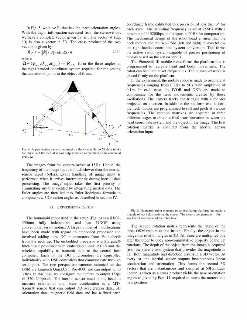
In Fig. 5, we have Rt that has the three orientation angles.
With the depth information extracted from the stereovision, we have a complete vector given by R̂ . The vector r̂ (Eq. 10) is also a vector in 3D. The cross product of the two vectors is given by
nrRrR ˆsinˆˆˆˆ !"!!=# (11)
where
!
" = (#new,$
new,%
new)& R
t+'t form the three angles in the right handed coordinate system required for the setting the actuators to point to the object of focus. Fig. 4. A perspective camera mounted on the Ocular Servo Module tracks the object and the inertial sensor outputs linear acceleration of the camera at every Δt.
The images from the camera arrive at 15Hz. Hence, the frequency of the image input is much slower than the inertial sensor input (60Hz). Event handling of image input is performed when it arrives intermittently during inertial data processing. The image input takes the first priority in eliminating any bias created by integrating inertial data. The Euler angles are then fed into Euler-Rodrigues formula to compute new 3D rotation angles as described in section IV.
VI. EXPERIMENTAL SETUP
The humanoid robot used in the setup (Fig. 6) is a iHs02,
350mm fully independent and has 21DOF using conventional servo motors. A large number of modifications have been made with regard to embedded processor and involved adding new DC micromotors from Faulhaber® from the neck-up. The embedded processor is a Stargate® Intel-based processor with embedded Linux RTOS and the wireless capability to transmit data to the central host computer. Each of the DC micromotors are controlled individually with DSP controllers that communicate through serial port. The two perspective cameras mounted on the OSM are Logitech QuickCam Pro 4000 and can output up to 30fps. In this case, we configure the camera to output 15fps @ 320×240pixels. The inertial sensor used in the head to measure orientation and linear acceleration is a MTx Xsens® sensor that can output 3D acceleration data, 3D orientation data, magnetic field data and has a fixed earth
coordinate frame calibrated to a precision of less than 3° for each axes. The sampling frequency is set at 256Hz with a baudrate of 115200bps and outputs at 60Hz for computation. The mechanical design of the robot head ensures that the neck motors and the two OSM (left and right) motors follow the right-handed coordinate system convention. This forms the active vision system capable of precise positioning of motors based on the sensor inputs.
The Pioneer® III mobile robot forms the platform that is programmed to recreate head and body movements. The robot can oscillate at set frequencies. The humanoid robot is placed firmly on the platform.
In the experiment, the mobile robot is made to oscillate at frequencies ranging from 0.2Hz to 5Hz with amplitude of 0.1m. In each case, the lVOR and OKR are made to compensate for the head movements created by these oscillations. The camera tracks the triangle with a red dot projected on a screen. In addition the platform oscillations, the neck motors are programmed to roll and pitch at various frequencies. The rotation matrixes are acquired at three different stages to obtain a final transformation between the head coordinate system and the object in the image. The first rotation matrix is acquired from the inertial sensor orientation input.
Fig. 5. Humanoid robot mounted on an oscillating platform that tracks a
triangle object held steady on the screen. The motors compensates for any lateral movement of the robot head.
The second rotation matrix represents the angle of the
three OSM motors at that instant. Finally, the object in the image has rotation angles in 3D. All three are multiplied one after the other to obey non-commutative property of the 3D rotations. The depth of the object from the image is acquired from the stereovision system that provides the magnitude in 3D. Both magnitude and direction results in a 3D vector. At every Δt, the inertial sensor outputs instantaneous linear acceleration and orientation. This forms the second 3D vectors that are instantaneous and sampled at 60Hz. Each update is taken as a cross product yields the new orientation angles as given by Eqn. 11 required to move the motors to a new position.
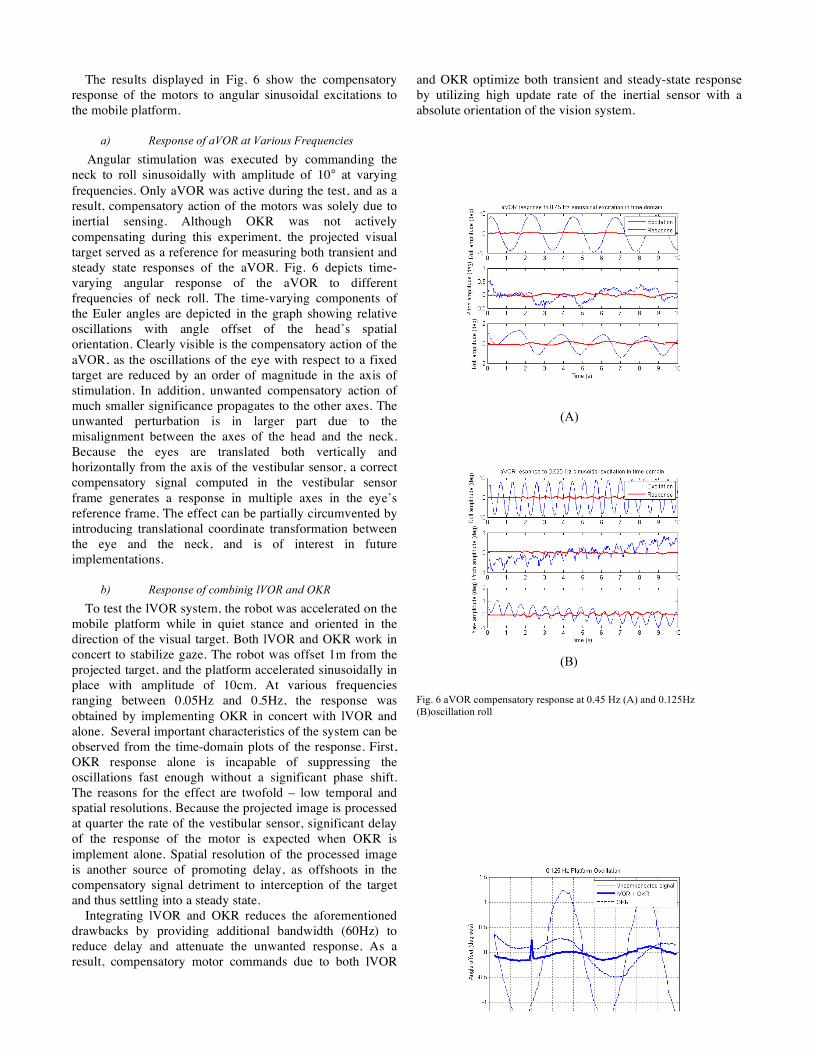
The results displayed in Fig. 6 show the compensatory response of the motors to angular sinusoidal excitations to the mobile platform.
a) Response of aVOR at Various Frequencies
Angular stimulation was executed by commanding the neck to roll sinusoidally with amplitude of 10° at varying frequencies. Only aVOR was active during the test, and as a result, compensatory action of the motors was solely due to inertial sensing. Although OKR was not actively compensating during this experiment, the projected visual target served as a reference for measuring both transient and steady state responses of the aVOR. Fig. 6 depicts time-varying angular response of the aVOR to different frequencies of neck roll. The time-varying components of the Euler angles are depicted in the graph showing relative oscillations with angle offset of the head’s spatial orientation. Clearly visible is the compensatory action of the aVOR, as the oscillations of the eye with respect to a fixed target are reduced by an order of magnitude in the axis of stimulation. In addition, unwanted compensatory action of much smaller significance propagates to the other axes. The unwanted perturbation is in larger part due to the misalignment between the axes of the head and the neck. Because the eyes are translated both vertically and horizontally from the axis of the vestibular sensor, a correct compensatory signal computed in the vestibular sensor frame generates a response in multiple axes in the eye’s reference frame. The effect can be partially circumvented by introducing translational coordinate transformation between the eye and the neck, and is of interest in future implementations.
b) Response of combinig lVOR and OKR
To test the lVOR system, the robot was accelerated on the mobile platform while in quiet stance and oriented in the direction of the visual target. Both lVOR and OKR work in concert to stabilize gaze. The robot was offset 1m from the projected target, and the platform accelerated sinusoidally in place with amplitude of 10cm. At various frequencies ranging between 0.05Hz and 0.5Hz, the response was obtained by implementing OKR in concert with lVOR and alone. Several important characteristics of the system can be observed from the time-domain plots of the response. First, OKR response alone is incapable of suppressing the oscillations fast enough without a significant phase shift. The reasons for the effect are twofold – low temporal and spatial resolutions. Because the projected image is processed at quarter the rate of the vestibular sensor, significant delay of the response of the motor is expected when OKR is implement alone. Spatial resolution of the processed image is another source of promoting delay, as offshoots in the compensatory signal detriment to interception of the target and thus settling into a steady state. Integrating lVOR and OKR reduces the aforementioned drawbacks by providing additional bandwidth (60Hz) to reduce delay and attenuate the unwanted response. As a result, compensatory motor commands due to both lVOR
and OKR optimize both transient and steady-state response by utilizing high update rate of the inertial sensor with a absolute orientation of the vision system. (A) (B) Fig. 6 aVOR compensatory response at 0.45 Hz (A) and 0.125Hz (B)oscillation roll
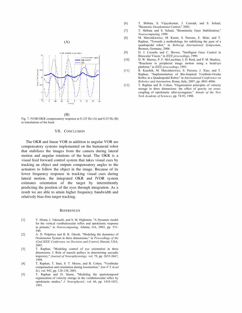
(A) (B) Fig. 7. lVOR/OKR compensatory response at 0.125 Hz (A) and 0.25 Hz (B) to translations of the head
VII. CONCLUSION
The OKR and linear VOR in addition to angular VOR are
compensatory systems implemented on the humanoid robot that stabilizes the images from the camera during lateral motion and angular rotations of the head. The OKR is a visual feed forward control system that takes visual cues by tracking an object and outputs compensatory angles to the actuators to follow the object in the image. Because of its lower frequency response in tracking visual cues during lateral motion, the integrated OKR and lVOR system estimates orientation of the target by intermittently predicting the position of the eyes through integration. As a result we are able to attain higher frequency bandwidth and relatively bias-free target tracking.
REFERENCES
[1] Y. Hirata, I. Takeuchi, and S. M. Highstein, "A Dynamic model
for the vertical vestibuloocular reflex and optokinetic response in primate," in Neurocomputing, Atlanta, GA, 2003, pp. 531-540.
[2] A. D. Polpitiya and B. K. Ghosh, "Modeling the dynamics of Oculomotor System in three dimensions," in Proceedings of the 42nd IEEE Conference on Decision and Control, Hawaii, USA, 2003.
[3] T. Raphan, "Modeling control of eye orientation in three dimensions. I. Role of muscle pulleys in determining saccadic trajectory," Journal of Neurophysiology, vol. 79, pp. 2653-2667, 1998.
[4] T. Raphan, T. Imai, S. T. Moore, and B. Cohen, "Vestibular compensation and orientation during locomotion," Ann N Y Acad Sci, vol. 942, pp. 128-138, 2001.
[5] T. Raphan and D. Sturm, "Modeling the spatiotemporal organization of velocity storage in the vestibuloocular reflex by optokinetic studies," J. Neurophysiol., vol. 66, pp. 1410-1421, 1991.
[6] T. Shibata, S. Vijayakumar, J. Conradt, and S. Schaal, "Biometric Ocoulomotor Control," 2002.
[7] T. Shibata and S. Schaal, "Biomimetic Gaze Stabilization," Neurocomputing, 1999.
[8] M. Marcinkiewicz, M. Kunin, S. Parsons, E. Sklar, and T. Raphan, "Towards a methodology for stabilizing the gaze of a quadrupedal robot," in Robocup International Symposium, Bremen, Germany, 2006.
[9] D. J. Coombs and C. Brown, "Intelligent Gaze Control in Binocular Vision," in IEEE proceedings, 1990.
[10] D. W. Murray, P. F. McLauchlan, I. D. Reid, and P. M. Sharkey, "Reactions to peripheral image motion using a head/eye platform," in IEEE proceedings, 1993.
[11] R. Kaushik, M. Marcinkiewicz, S. Parsons, J. Xiao, and T. Raphan, "Implementation of Bio-Inspired Vestibulo-Ocular Reflex in a Quadrupedal Robot," in International Conference on Robotics and Automation, Roma, Italy, 2007, pp. 4861-4866.
[12] T. Raphan and B. Cohen, "Organisation principles of velocity storage in three dimensions: the effect of gravity on cross-coupling of optokinetic after-nystagmus," Annals of the New York Academy of Sciences, pp. 74-92, 1988.
Related Documents