1 COM 360

COM 360
Dec 30, 2015
COM 360. Chapter 3. Packet Switching. Limitations of Point-To-Point Networks. Problem: Not all Networks are Directly Connected Limit to number of hosts that can be attached (e.g. Ethernet – 1024 maximum) Limit to distance a network can serve (e.g. Ethernet 2500 meters maximum) - PowerPoint PPT Presentation
Welcome message from author
This document is posted to help you gain knowledge. Please leave a comment to let me know what you think about it! Share it to your friends and learn new things together.
Transcript

1
COM 360

2
Chapter 3
Packet Switching

3
Limitations of Point-To-Point Networks
• Problem: Not all Networks are Directly Connected
• Limit to number of hosts that can be attached (e.g. Ethernet – 1024 maximum)
• Limit to distance a network can serve (e.g. Ethernet 2500 meters maximum)Next goal is to build networks that can be global in
scale and to enable communication between hosts that are not directly connected.

4
Comparison to Phone System
• Phone is not connected to every person you might call- instead it is connected to an exchange with a switch.
• The switch creates the illusion that you are connected to the person at the other end of the call.
• Similarly computer systems use packet switches to enable packets to travel form one host to another, even when there is no direct connection between the hosts.

5
Packet Switches
• A Packet Switch is a device with several inputs and outputs leading to and from the hosts connected to the switch.
• Main role of the switch is to take packets that arrive on the input and forward (or switch) them to the right output for their destination.
• If packet arrival rates exceed the capacity of the output, the switch queues (or buffers) them. This is the problem of contention and the switch is said to be congested.

6
Switching and Forwarding• A switch is a device that allows us to
interconnect links to form larger networks.• A switch is a multi-input, multi-output device,
which transfers packets from an input to one or more outputs.
• A switch adds a star topology to the point-to-point link (Ethernet) and ring (802.5 and FDDI)
• Topologies.

7
Topologies
• Networks can be classified by shape or topology. The most common are:
• Bus
• Ring
• Star

8
Bus Topology• Networks with a bus topology consist of a
long cable to which the computers attach. Any computer connected to the cable can send a signal and all computers receive the message.
9
Ring Topology• All computers are connected in a closed loop. • Each computer is connected to exactly two others. • The ring is a logical connection and the physical
connections might look different and do not have to appear circular.

10
Star Topology• All computers attach to a central point or hub:

11
Star Topology in Practice
• Previous diagram is idealized; usually, connecting cables run in parallel to computers:

12
Reasons for Multiple Topologies
• Each topology has advantages and disadvantages:
Star - protects the network from damage, since each cable connects only one computer.
Ring - makes connections and coordination easier, but if one cable is damaged or one computer crashes, the entire network is disabled.
• Bus - requires fewer wires than the star, but like a ring- if the main cable is damaged, the entire network is disabled.

13
A Switch Provides a Star Topology

14
Properties of a Star Topology• Even though a switch has a limited number of inputs
and outputs, large networks can be built by connecting switches.
• We can connect switches to each other and to hosts using point-to-point links allowing us to build large geographic networks.
• Adding additional hosts to a switch does not necessarily decrease the network performance.
• Every host on a switch has its own link to the switch and thus may transmit simultaneously.

15
Switching or Forwarding
• Switched networks are scalable or capable of growing to large numbers of nodes.
• Switching or forwarding is the main function of the network layer of the OSI Architecture.

16
Example Protocol Graph Running on a Switch
T3 T3 STS-1
Switchingprotocol

17
Example Switch for Previous Graph
Inputports
T3T3
STS-1
T3T3STS-1
Switch
Outputports
With 3 input and 3 output ports

18
Switching• How does a switch determine the port for a packet?• It looks at the header for an identifier or address
– Datagram or connectionless approach
– Virtual circuit or connection-oriented approach
– Source routing – less common
• Assumptions: nodes must have globally unique identifiers and ports of each switch have identifiers (either numbers or names of connecting nodes)

19
Datagrams
• Idea behind a datagram is simple• A datagram is the basic transmission unit in the
Internet architecture. • Datagram networks are connectionless.• Every packet must contain a complete destination
address• Switch consults a forwarding or routing table • Routing is a process by which nodes exchange
information to build a routing table.

20
An Example Network
0
132
0
1 3
2
013
2
Switch 3 Host B
Switch 2
Host A
Switch 1
Host C
Host D
Host EHost F
Host G
Host HDatagram forwarding

21
Forwarding Table for Switch 2
Destination Port
A 3
B 0
C 3
D 3
E 2
F 1
G 0
H 0

22
Characteristics of Connectionless Datagram Networks
• A host can send a packet anywhere, anytime, since switches immediately forward them.
• When a host sends a packet, it does not know if the network can deliver it.
• Each packet is forwarded independently of previous packets and possibly by different paths.
• A switch or link failure may not have serious effects since it may be possible to find an alternate route. This was a goal of the ARPANET.
• It was the ability to route around failures that led to a datagram based design ( especially important to the military).

23
Virtual Circuit Switching
• Connection –oriented model uses a virtual circuit (VC)• A widely used virtual circuit protocol is the
Transmission Control Protocol (TCP).• Switched virtual circuits (SVC) are generally set up on
a demand basis and are disconnected when the call is terminated.
• A permanent virtual circuit (PVC) can be established as an option to provide a dedicated circuit link between two facilities.

24
Implementing A Virtual Circuit
• Two stage process:– Connection setup stage- establishes a connection
between the source and destination hosts and creates a VC table in each switch.
– Data transfer stage- host puts an (VCI) identifier in the header and send it to the switch
• When the host no longer wants to send data it tears down the connection and the switch removes the relevant entries in the table.

25
Virtual Circuit Table
• An entry in a virtual circuit table for each switch contains:
• A virtual circuit identifier (VCI)- that uniquely identifiers the connection;
• An incoming interface;• An outgoing interface;• A potentially different VCI that will be used for
outgoing packets.

26
Sending a Packet on a VC
• If a packet arrives on an incoming interface of the switch and that packet contains the designated VCI value in its header, then it is sent out on the outgoing interface with the specified VCI value now included in its header.
• Whenever a new connection is created, we need to assign a new VCI on each link and assure that the link is not currently in use by some existing connection.

27
Example of a Virtual Circuit
01
2
30
1
2
3
0
1
2
3
0
1
2
3
Host A
Host B
Switch 3
Switch 2Switch 1

28
Virtual Circuit Tables
Switch Incoming Interface
Incoming VCI
Outgoing Interface
Outgoing VCI
1 2 5 1 11
2 3 11 2 7
3 0 7 1 4

29
A Packet is Sent into a VC From A to B
0
1
2
3
0
13
01
2
3
0
1
22
3
Host A Host B
Switch 3
Switch 2Switch 1
5
11
A puts VCI value of 5 in header and sends to switch 1. Switch 1 Uses the table and puts the value 11in the header and sends it to Interface 3 on switch 2.

30
Packet Makes Its Way Though a VC
0
1
2
3
0
1
2
3
0
1
2
3
0
1
2
3
Host A Host B
Switch 3
Switch 2Switch 1
7
11
Switch 2 looks up the value in its VC table, puts the value 7 in the header and send it out on interface 2 to switch 3. This continues until the packet arrives at B.

31
Virtual Circuits
• Note that the combination of the VCI of packets as they are received at the switch and the interface on which they are received uniquely identifies the virtual connection.
• The VCI has link local scope and is only significant for that connection
• When a new connection is created, a new VCI has to be assigned to the connection.
• Need to insure that the chosen VCI on a link is not currently in use by some existing connection.

32
Virtual Circuits
• To establish a connection:– The network administrator can configure the state in
which case it is called “permanent”(PVC).– A host can send messages into the network to cause
the state to be established. This is referred to as “signalling” and the resulting circuits are said to be switched (SVC).

33
Virtual Circuit Switching• By the time the host gets the go-ahead to send the data,
it knows a lot about the network.• The connection-oriented model does the following:
– Allocates buffers to each virtual circuit;
– Runs the sliding window protocol between each pair of nodes;
– The circuit is rejected by the host if there are not enough buffers available
• Thus each node is ensured of having the buffers it needs. This is called hop-by-hop control.

34
Datagram Network
• There is no connection phase and each switch processes each packet individually.
• Each packet competes with others for buffer space. If there are no buffers, the packet is discarded.
• It is possible to distinguish among the packets to try to ensure that they receive a fair share of the buffers

35
Quality of Service
• Quality of Service (QoS) means that the network gives the user some kind of performance related guarantee, which implies that the switches set aside the resources to meet this guarantee.

36
Examples of Virtual Circuits
• Frame Relay- simple implementation -provides some basic quality of service and congestion avoidance features- used in the construction of virtual private networks (VPN).
• Asynchronous Transfer Mode (ATM)

37
Frame Relay Packet Format
Variable
Control
8
Address
16
Framechecksum
16
Flag(0x7E)
8
Flag(0x7E)
8
Data
Frame Relay packet format provides a good example of a packet used for virtual circuit switching.
38
Contention and Congestion
• Contention occurs when multiple packets are queued at a switch because the are competing for the same output link.
• Congestion means that the switch has so many packets queued that it runs out of buffer space and has to start dropping packets.
• The Datagram model experiences congestion.

39
Source Routing
• Source Routing is a third approach to switching. All the information that is needed to switch a packet across the network is provided by the source host.
• One way to do this is to put an ordered list of switch ports in the header and to rotate the list so that the next port is always at the front of the list.
• (Not commonly used today.)

40
Source Routing In A Switched Network
0
132
01 3
2
0
13
2
0
13
2
3 0 1 3 01
30 1
Switch 3
Host B
Switch 2
Host A
Switch 1
Switch reads the rightmost-number

41
Source Routing• Assumes that the host knows enough about the
topology to form a header that has all the switches.• We cannot predict how big the header may be, since it
must be able to hold one word of information for every switch on the path.
• There are some variation of this approach:– Instead of rotating the header, the switch can strip off the
element just used– The header can carry a pointer to the next port
• Can be used in both datagram networks and virtual circuits, but it does not scale well.

42
Handling Headers For Source Routing
Header enteringswitch
Header leavingswitch
(a) (b) (c)
D C B A D C B A
D C BA D C B
Ptr D C B A
Ptr D C B A
a) rotation b) stripping c) pointer
These labels are read from right to left.
43
Bridges and LAN Switches• Originally repeaters were used to connect a pair of
Ethernet segments.• An alternative was to put a node between the two
Ethernets and have the node forward frames. This node is called a bridge.
• Bridges just accept LAN frames and forward them on the outputs.
• This provides a way to increase the total bandwidth of the network. If a segment can carry 10Mbps, a bridge can carry as much as 10n Mbps, for n ports on the bridge.

44
Learning Bridges• Bridges do not have to forward all the frames it receives.• It can learn on which port each host resides.• A table can be downloaded and referred to when each
new frame arrives.• A bridge can learn this information by inspecting the
frames it receives and updating its table. When the bridge boots the table is empty and entries are added over time. If a frame is not on the table it is forwarded to all.

45
A Learning Bridge
A
Bridge
B C
X Y Z
Port 1
Port 2
46
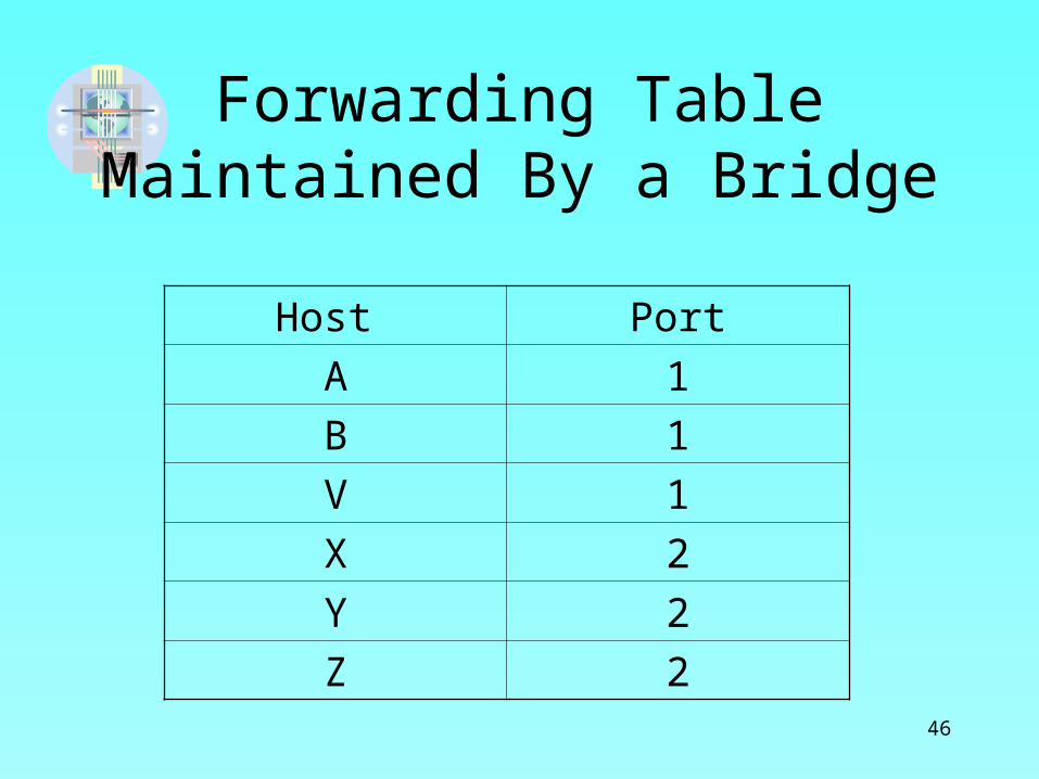
Forwarding Table Maintained By a Bridge
Host Port
A 1
B 1
V 1
X 2
Y 2
Z 2

47
Spanning Tree Algorithm
• Extending LANS with Bridges works well until it has a loop in it, which can allow a frame to circulate forever.
• A loop can be introduced by an administrator, when a network spans multiple departments.
• Bridges run a distributed spanning tree algorithm, which is a sub-graph which keeps all of the original vertices and eliminates some of the edges.

48
Extended LAN With LoopsA
C
E
D
B
K
F
H
J
G
I
B3
B7
B4
B2
B5
B1
B6

49
Spanning Tree With Some Ports Not SelectedA
C
E
D
B
K
F
H
J
G
I
B5
B2
B3
B7
B4
B1
B6
B1 is the root node, B3 and B5 are connected to LAN A and will use B5 since it is closer. B5 and B7 are connected to LAN B.B5 is the designated bridge because it has smaller ID and both areequidistant.

50
Graphs and Spanning Trees
(a) (b)
a) Cyclic graph b) Corresponding spanning tree

51
Broadcast and Multicast• Bridges forward unicast frames from one LAN to
another.• Goal of a bridge is to extend a LAN across multiple
networks, and most LANS support both broadcast and multicast, bridges also need to support these.
• Broadcast- each bridge forwards a frame out on each active port
• Multicast- similar to broadcast and allows each host to decide whether or not to accept the frame.

52
Limitations of Bridges
• The bridge-based solution is used only to connect a limited number of similar LANS.
• Scale- cannot connect more than a few LANs with bridges.
• Homogeneity- bridges are fairly limited in the kinds of LANs they can connect. They make use of the network frame headers, which must have same format. Can connect Ethernet to Ethernet, 802.5 to 802.5, etc.

53
Virtual LANs
• For scalability, LANs may be extended by using Virtual LANs (VLAN).
• VLANs allow a single extended LAN to be partitioned into several separate LANs, each with an identifier (called a color), and packets can only travel from one segment to another if both have the same identifier.
• This limits the number of segments that will receive a broadcast packet.

54
Virtual LANs With Common Backbone
W X
B1 B2
Y Z
VLAN 100 VLAN 100
VLAN 200 VLAN 200
Any broadcast packet will be received by any host.
Suppose W,X and Y,Z are two VLANs and B1, B2 belong to both.
A broadcast packet from X will be sent only to W

55
Cell Switching (ATM)
• Asynchronous Transfer Mode became an important technology in the late 1980’s and early 1990’s.– It was used by the telephone industry– IT became available for use as a high speed
switching technology, just when other shared media like Ethernet and X.25 were becoming too slow.

56
ATM
• A network technology based on transferring data in cells or packets of a fixed size.
• The cell used with ATM is relatively small compared to units used with older technologies.
• The small, constant cell size allows ATM equipment to transmit vide, audio, and computer data over the same network, and assure that no single type of data monopolizes the line.
• This differs from other technologies based on packet-switched networks (such as the Internet ot the Ethernet), in which variable sized packets (called frames) are used.

57
ATM
• ATM is a connection-oriented, packet switching technology, which uses virtual circuits.
• The connection set-up phase is called signaling.• When a virtual connection is set up, the address of the
destination is put in the signaling message, using one of several formats.
• ATM packets are of fixed length- 53 bytes (header and a 48 byte payload) and are called cells.

58
Cells
• Cells, in contrast to other packets, are fixed in length and small in size.
• Another property of cells relates to the behavior of queues. Fixed-length cells means that a queue output is not tied up for more time that it takes to transmit one cell.
• Queues of cells also tend to be shorter that queues of packets.

59
Cell Size
• Why use fixed size cells?• Fixed packets made building fast, scalable switches
easier because:1. It is easier to build hardware to do simple jobs and
processing packets is simpler when you know the length of each packet.
2. If all packets are the same length, you can have many switching elements doing the same thing in parallel, and each taking the same time to do its job.
• Enabling parallelism, improves the scalability of switch design.

60
Cell size
• The motivation for the use of small data cells was the reduction of jitter(delay variance) in the multiplexing of data streams;
• Reducing jitter and also end-to-end round-trip delays is particularly important when carrying voice traffic.

61
Cell Size
• Having decided to use small fixed-length packets, the next question is: “What is the right length for these cells?”
• The resulting size was a compromise between the US proposed 64 bye size and the European 32 byte size. Unfortunately, it is not a power of 2.

62
Cell Format
• The ATM cell comes in two different formats:– UNI (User-network interface)- used between a
telephone company and it customer.
– NNI ( Network-to-Network Interface) is used between pairs of phone companies.
• The primary difference is that the NNI format replaces the GFC(generic flow control) field with 4 extra bits of VPI ( virtual path identifier).
63
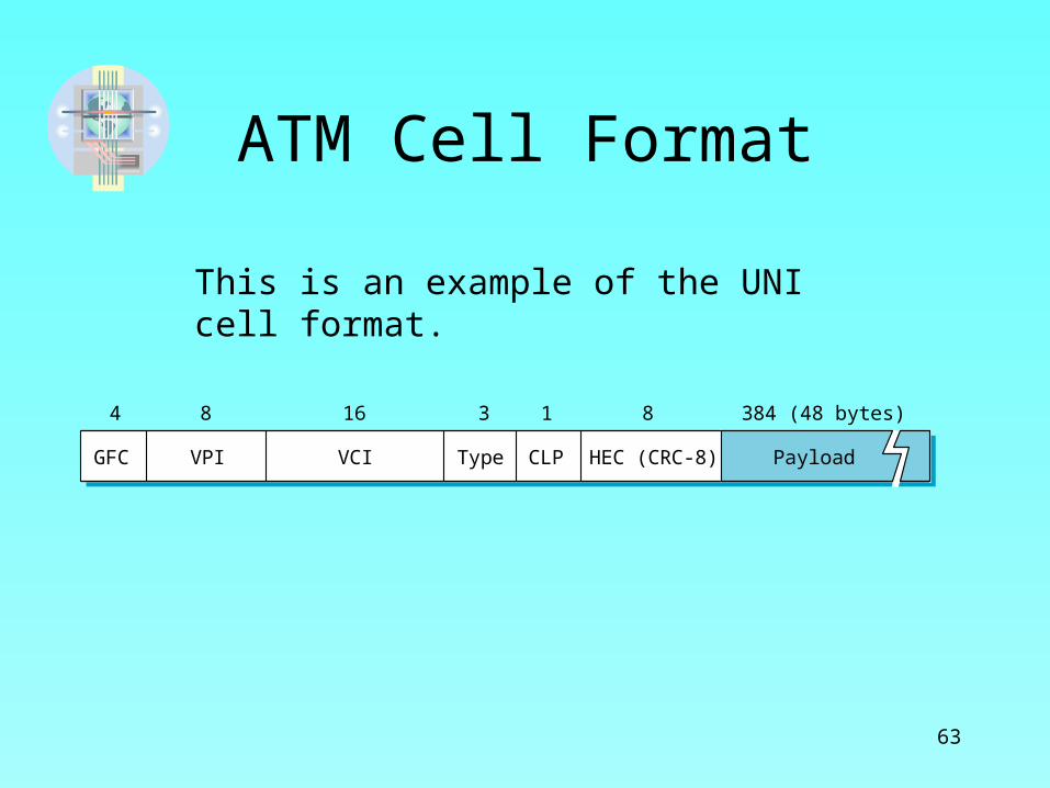
ATM Cell Format
GFC HEC (CRC-8)
4 16 3 18
VPI VCI CLPType Payload
384 (48 bytes)8
This is an example of the UNI cell format.

64
Segmentation and Reassembly• Up until now we have assumed that a low-level
protocol could accept the packets handed down form a higher –level protocol, attach its header and pass the packet down.
• This is not possible with ATM, since the packets are often larger than 48 bytes and will not fit in the ATM payload.
• Solution: Fragment the packet at the source.
65
Segmentation and Reassembly• Up until now we have assumed that a low-level
protocol could accept the packets handed down form a higher –level protocol, attach its header and pass the packet down.
• This is not possible with ATM, since the packets are often larger than 48 bytes and will not fit in the ATM payload.
• Solution: Fragment the packet at the source.

66
Segmentation and Reassembly
• The technique called fragmentation and reassembly is often called segmentation and reassembly (SAR) in the case of ATM.
• It involves fragmenting the packet, transmitting the individual packets and then reassembling the fragments back together at the destination.
• It is more of a problem with ATM, than with a network with a maximum packet size of 1500 bytes.
• An additional layer, the ATM Adaptation Layer (AAL) was added to handle this.

67
Segmentation and Reassembly in ATM
■ ■ ■ ■ ■ ■
AAL
ATM
AAL
ATM
ATM supports many services, including voice, video, and data, and its service have different AAL needs.
AAL3 is used by connection oriented services (like X.25) and AAL4 is used by connectionless services ( such as IP).
The relation between AAL and ATM is shown here:

68
ATM Adaptation Layer 3/4
• Main function of AAL3/4 is to provide variable length packets to be transported across ATM networks.
• Supports segmentation and reassembly

69
ATM Adaptation Layer 3/4 Packet Format
CPI Btag BASize Pad 0 Etag Len
8 16 0─24 8 8 16< 64 KB8
User data

70
ATM Cell format for AAL 3/4
ATM header Length CRC-10
40 2 4
SEQ MIDType Payload
352 (44 bytes)10 6 10

71
Encapsulation and Segmentation for AAL3/4
CS-PDUheader
CS-PDUtrailer
User data
44 bytes 44 bytes 44 bytes 44 bytes
ATM header
AAL header
Cell payload
AAL trailer
Padding

72
ATM Adaptation Layer 5
• Replaces the type field of AAL3/4 with 1 framing bit in the ATM header, simplifying it.
• AAL5 is now preferred for transmitting IP datagrams over ATM
• Uses bandwidth more efficiently and it has a much simpler design than AAL3/4.

73
ATM Adaptation Layer 5 Packet Format
CRC-32
< 64 KB 0 ─47 bytes 16 16
ReservedPad Len
32
Data

74
Encapsulation and Segmentation for AAL5
User data
48 bytes 48 bytes 48 bytes
ATM header Cell payload
Padding
CS-PDUtrailer

75
Virtual Paths
• ATM uses a 24 bit identifier for virtual circuits, and it is split into two parts:– 8 bit virtual path identifier (VPI) and – 16 bit virtual circuit identifier (VCI)
• This creates two levels of connections
• Virtual path acts like a fat pipe that contains a bundle of virtual circuits

76
Example of a Virtual Path
Public network
Network BNetwork A
77
Advantage of Virtual Path
• Although there may be thousands of virtual connections across the public network, the switches in the public network behave as though there is only one connection.
• This requires much less less connection-state information in the switches.
78
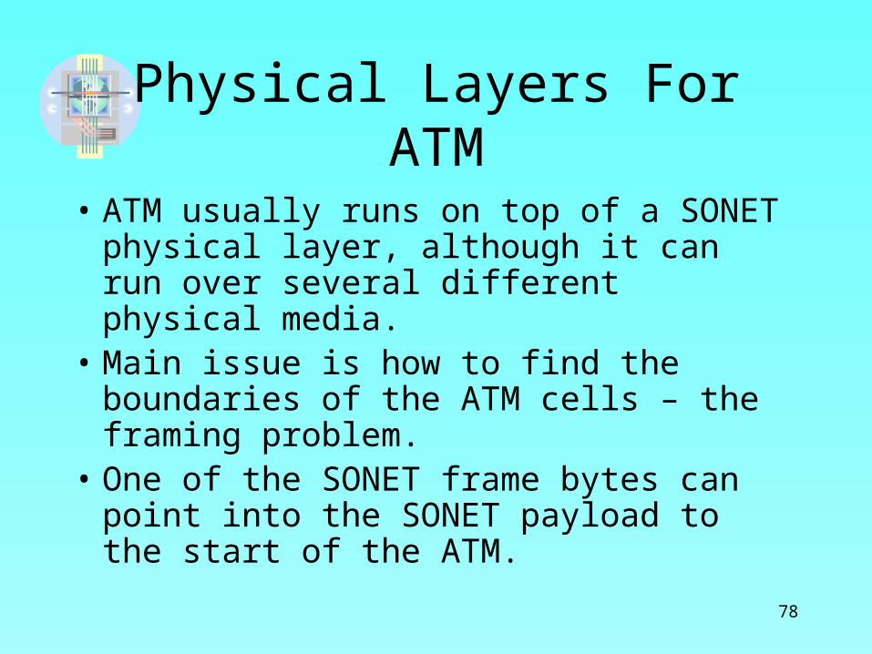
Physical Layers For ATM
• ATM usually runs on top of a SONET physical layer, although it can run over several different physical media.
• Main issue is how to find the boundaries of the ATM cells – the framing problem.
• One of the SONET frame bytes can point into the SONET payload to the start of the ATM.

79
ATM in the LAN
• ATM is a switched technology, whereas Ethernet and 802.5 were shared-media technologies.
• ATM was designed to work with speeds > 155Mbps, compared to the original Ethernet
(10 Mbps) and token rings (4 or 6 Mbps)• ATM switches have a performance advantage over
shared media networks.• ATM does not have distance limitations

80
ATM Used as a LAN Backbone
ATM links
Ethernet links
Ethernet switch
ATM switch
ATM-attachedhost
E1
H5
H6
H7
H1E3
H2
H4
H3
E2
ATM became popular for the high-performance backbone of larger LANs. Hosts were connected to Ethernet switches, which were connected to ATMs.

81
Gigabit Ethernet
• Gigabit Ethernet links use the original framing, but are usually point-to-point fiber links and can run over longer distances (up to several kilometers).
• Same approach can scale up to 10 Gbps links.

82
Problems with ATM in a LAN
• ATM behaves differently than a shared media LAN, which supports broadcast and multicast.
• ATM can be made to behave like a LAN, called LAN emulation. This involves adding new protocols and addressing.
• LAN Emulation (LANE) adds functionality, through the addition of a number of servers.
• Devices that connect to an ATM network- hosts, bridges, routers are referred to as LAN emulation clients. (LEC)

83
LAN Emulation• Servers that are required to build an emulated LAN
are:– LAN emulation configuration server (LECS)– LAN emulation server (LES)– Broadcast and unknown server (BUS)
• These can be physically located in one or more devices
• The LECS and LES perform configuration functions and the BUS makes data transfer resemble that of a shared media LAN.
84
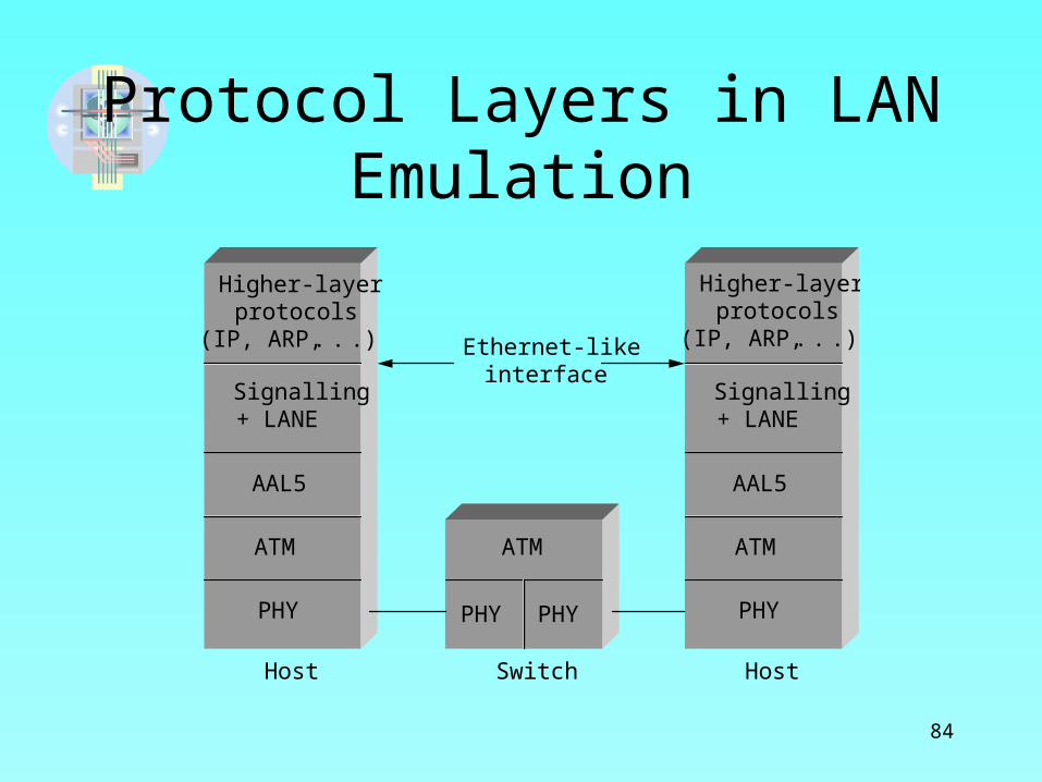
Protocol Layers in LAN Emulation
Host Switch Host
Ethernet-likeinterface
Higher-layerprotocols
(IP, ARP, . . .)
Signalling+ LANE
AAL5
ATM
PHY
Higher-layerprotocols
(IP, ARP, . . .)
Signalling+ LANE
AAL5
ATM
PHY
ATM
PHY PHY
85
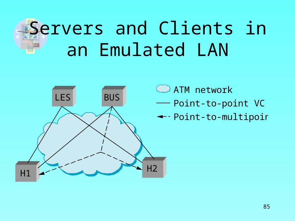
Servers and Clients in an Emulated LAN
BUSLESATM network
Point-to-point VC
Point-to-multipoint VC
H1 H2

86
Implementation and Performance
• There is a simple way to build a switch:– Buy a general purpose workstation and equip it
with a number of NIC cards.– Such a device with suitable software can
receive packets on its interfaces and perform switching functions, and send packets out oon its interfaces.
– Very similar to low-end routers.

87
Workstation Used as a Packet Switch
I/O bus
Interface 1
Interface 2
Interface 3
CPU
Main memory
Shows path of a packet which uses DMA. Problem all packets pass through I/O buss twice. Throughput it either ½ main memory bandwidth or ½ the I/O bus bandwidth, whichever is less.

88
Problem With Using Workstation As A Switch
• Main problem –performance is limited by fact that all packets must pass through single I/O bus twice.
• Cost of processing a packet (parsing the header, deciding on which output link to transmit it) will dominate. ( Bad for short packets.

89
Example
• Suppose a workstation can perform processing to switch 500,000 packets per second (pps).
• If a packet is short (64 bytes) then • Throughput = pps x (bits per packet) = 500 x 103 x 64 x 8 = 256 x 106
which is a throughput of 256 Mbps – much below today’s expected throughput.

90
Defining Throughput• If a switch has n inputs that each support a link speed
of si the best possible throughput is the sum of all the si
• This is not achievable in practice, since a switch can only handle traffic arriving at full link speed on all inputs if it is evenly distributed.
• For Ethernet switches, the size of the packets also affects the switch performance.
• Throughput of the switch is a function of the traffic.

91
Traffic Modeling
• A traffic model approximates the behavior of real data traffic.
• It attempts to answer several important questions:– When do packets arrive?– What outputs are they destined for?– How big are they?

92
Ports• The input or output on which packets are received or
sent.• A switch consists of input ports, output ports and a
fabric.• There is usually at least one control process that
communicates with the ports either directly or via the switch fabric.
• The ports communicate with the outside world.• Ports contain fiber optic receivers and lasers, buffers to
hold packets and other circuitry. • The fabric delivers the packet to the right output port.

93
Ports• The ports maintain a list of virtual circuit
identifiers that are in use.
• The input port receives a steady stream of packets and has about 200 nanoseconds to process a packet. (See p. 214)
• Ports also buffer packets on both input and output ports.
• Buffering in the fabric is called internal buffering.

94
A 4 x 4 Switch
Switchfabric
Controlprocessor
Outputport
Inputport
An input buffer is often implemented as a FIFO. Only one packet at a time can be forwarded to a specific output Port, the rest remain in the buffers and can prevent packets further back from going to their Ports

95
Illustration of Head-Line Blocking
Switch
2
21
Port 1
Port 2
Notice that a packet destined for Port 1 is blocked by a packet contending for Port 2. This can limit throughput to 59% of its maximum and should be avoided.

96
Fabrics• A fabric is the part of a switch that actually does the
routing. It should move packets with minimal delay.– Shared bus- found in workstations used as a switch
– Shared memory- packets are read into memory by input port and read by output port
– Crossbar- a matrix of pathways configured to connect any input and output ports
– Self routing- rely on information in header to direct packets – most scalable
97
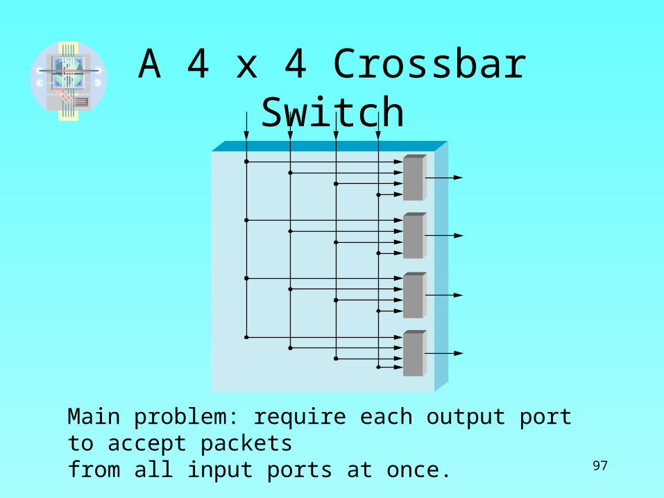
A 4 x 4 Crossbar Switch
Main problem: require each output port to accept packets from all input ports at once.
98
Self- Routing
• Self-routing fabrics rely on information in the packet header to direct each packet to its correct output.
• A self-routing header is appended to the packet by the input port and is removed before the packet leaves the switch.

99
Self-Routing HeaderSwitchfabric
Outputport
Inputport
Original packetheader
Switchfabric
Outputport
Inputport
Self-routingheader
Switchfabric
Outputport
Inputport
(a)
(b)
(c)
a) Packet arrives at input Port
b) Input Port attaches header
c) Self-Routing header is removed

100
Routing Packets Through a Banyon Network
001
011
110
111
001
011
110
111
Banyon Network is an Arrangement of 2x2Switching elements that routes packets to the correctOutput without collisions if the packets are presented In ascending order. It uses the “perfect shuffle”wiring pattern

101
Summary• Large scalable networks are built using
switches.• An important application of switching is the
interconnection of shared-media LANs.• Virtual Circuit switching is used in Frame
Relay and ATMs.• ATMs use cells, or short fixed length packets.• Switches forward packets at a very high rate.

102
Open Issue: Future of ATM
• Success of Ethernet switches has made ATMs less popular. Gigabit Ethernet and 10-Gigabit Ethernet have provided high speed connections to servers.
• Another factor limiting the use of ATMs is the Internet, with a service that delivers IP packets.
• ATMs are still used in Virtual Circuits but are being challenged by newer technologies.

103
Figure 3.33 for Ex. 1 and 2
0
132
0
1 3
2
013
2
Switch 3
Switch 2
Switch 4
Host A
Host BHost J
Switch 1
Host C
Host D
Host E
Host I
213
0
Host H
Host F
Host G
104
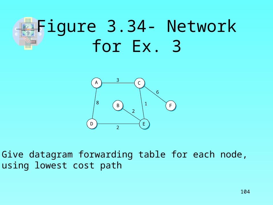
Figure 3.34- Network for Ex. 3
2
3
6
2
8 1
D
A
F
E
B
C
Give datagram forwarding table for each node, using lowest cost path

105
Figure 3.35- for Ex. 4
S11 3
2
A
B
S21 3
2
S31 3
2
C
S41
2
DOUT

106
Figure 3.36Virtual Circuit Switches for Ex. 5
S11 3
2
A E
B
S21 3 3
2
C
S31
2
D

107
Figure 3.37 for Ex 13, 14A
C
E
D
B
F
H
J
G
I
B7
B1
B2
B5
B6
B3
B4

108
Figure 3.38 for Ex. 15, 16
B3 C
A B1 B2
B4 D

109
Figure 3.39 for Ex. 17
Z
X B1 B2 B3
Y W

110
Figure 3.40 for Ex. 18
B1 B3B2

111
Figure 3.41 for Ex 19, 20
B1
L
M
B2
Related Documents