ColorMod: Recoloring 3D Printed Objects using Photochromic Inks Parinya Punpongsanon, Xin Wen, David S. Kim, Stefanie Mueller MIT CSAIL, Cambridge, MA, USA [email protected], [email protected], [email protected], [email protected](Email moved for reviews) ABSTRACT Recent research has shown how to change the color of ex- isting objects using photochromic materials. These materi- als can switch their appearance from transparent to colored when exposed to light of a certain wavelength. The color remains active even when the object is removed from the light source. The process is fully reversible allowing users to recolor the object as many times as they want. So far, these systems have been limited to single color changes, i.e. changes from transparent to colored. In this paper, we present ColorMod, a method to extend this ap- proach to multi-color changes (e.g., red-to-yellow). We accomplish this using a multi-color pattern with one color per voxel across the surface of the object. When recoloring the object, our system locally activates only those voxels that have the desired color and turns all other voxels off. We describe ColorMod’s hardware/software system and its user interface. The user interface comes with a conversion tool for 3D printing and a painting tool for matching physi- cal voxels with the desired appearance. We also provide our own material formula for a 3D-printable photochromic ink. Author Keywords personal fabrication; 3D printing; projector-camera system. ACM Classification Keywords H5.2. [Information interfaces and presentation]: User Inter- faces. INTRODUCTION With recent advances in 3D printing, objects can now be fabricated in full-color [1]. However, once an object is fab- ricated, the color is permanent and cannot be changed again: every change requires printing a new version leading to additional printing time and material usage. Figure 1. ColorMod is a method that allows users to recolor objects even after fabrication. To accomplish this, ColorMod uses (a) 3D printing of photochromic inks in a dense multi- color pattern. (b) When users apply a specific color texture using ColorMod’s user interface, only the voxels with the matching color are activated. (c) The same object recolored multiple times. To avoid reprinting objects, researchers suggested to digi- tally project the desired color onto the object [26, 16, 35]. However, the color disappears once the projector is switched off or the object is removed from the setup. Recently, researchers have started to explore a different approach: By using photochromic materials [3] that can switch their appearance from transparent to colored when exposed to light of a certain wavelength, the color of exist- ing objects can be changed without the need to refabricate it. The color remains even when the object is removed from under the light source. This process is fully reversible, thus allowing users to recolor the object as many times as they want. Permission to make digital or hard copies of all or part of this work for personal or classroom use is granted without fee provided that copies are not made or distributed for profit or commercial advantage and that copies bear this notice and the full citation on the first page. Copyrights for components of this work owned by others than the author(s) must be honored. Abstracting with credit is permitted. To copy otherwise, or republish, to post on servers or to redistribute to lists, requires prior specific permission and/or a fee. Request permissions from [email protected]. CHI 2018, April 21–26, 2018, Montreal, QC, Canada. Copyright is held by the owner/author(s). Publication rights licensed to ACM. ACM ISBN 978-1-4503-5620-6/18/04…$15.00 https://doi.org/10.1145/3173574.3173787

Welcome message from author
This document is posted to help you gain knowledge. Please leave a comment to let me know what you think about it! Share it to your friends and learn new things together.
Transcript
ColorMod: Recoloring 3D Printed Objects using Photochromic Inks
Parinya Punpongsanon, Xin Wen, David S. Kim, Stefanie Mueller MIT CSAIL, Cambridge, MA, USA
[email protected], [email protected], [email protected], [email protected](Email address moved for reviews)
ABSTRACT Recent research has shown how to change the color of ex-isting objects using photochromic materials. These materi-als can switch their appearance from transparent to colored when exposed to light of a certain wavelength. The color remains active even when the object is removed from the light source. The process is fully reversible allowing users to recolor the object as many times as they want.
So far, these systems have been limited to single color changes, i.e. changes from transparent to colored. In this paper, we present ColorMod, a method to extend this ap-proach to multi-color changes (e.g., red-to-yellow). We accomplish this using a multi-color pattern with one color per voxel across the surface of the object. When recoloring the object, our system locally activates only those voxels that have the desired color and turns all other voxels off.
We describe ColorMod’s hardware/software system and its user interface. The user interface comes with a conversion tool for 3D printing and a painting tool for matching physi-cal voxels with the desired appearance. We also provide our own material formula for a 3D-printable photochromic ink.
Author Keywords personal fabrication; 3D printing; projector-camera system.
ACM Classification Keywords H5.2. [Information interfaces and presentation]: User Inter-faces.
INTRODUCTION With recent advances in 3D printing, objects can now be fabricated in full-color [1]. However, once an object is fab-ricated, the color is permanent and cannot be changed again: every change requires printing a new version leading to additional printing time and material usage.
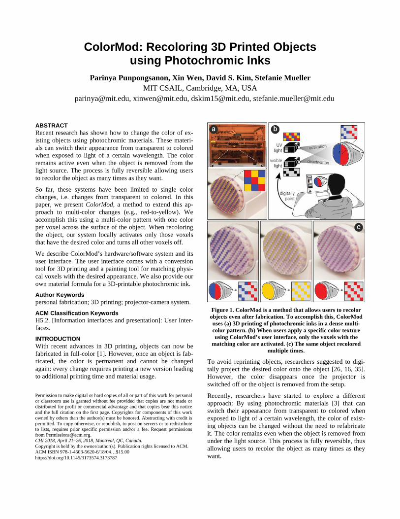
Figure 1. ColorMod is a method that allows users to recolor
objects even after fabrication. To accomplish this, ColorMod uses (a) 3D printing of photochromic inks in a dense multi-color pattern. (b) When users apply a specific color texture using ColorMod’s user interface, only the voxels with the
matching color are activated. (c) The same object recolored multiple times.
To avoid reprinting objects, researchers suggested to digi-tally project the desired color onto the object [26, 16, 35]. However, the color disappears once the projector is switched off or the object is removed from the setup.
Recently, researchers have started to explore a different approach: By using photochromic materials [3] that can switch their appearance from transparent to colored when exposed to light of a certain wavelength, the color of exist-ing objects can be changed without the need to refabricate it. The color remains even when the object is removed from under the light source. This process is fully reversible, thus allowing users to recolor the object as many times as they want.
Permission to make digital or hard copies of all or part of this work for personal or classroom use is granted without fee provided that copies are not made or distributed for profit or commercial advantage and that copies bear this notice and the full citation on the first page. Copyrights for components of this work owned by others than the author(s) must be honored. Abstracting with credit is permitted. To copy otherwise, or republish, to post on servers or to redistribute to lists, requires prior specific permission and/or a fee. Request permissions from [email protected]. CHI 2018, April 21–26, 2018, Montreal, QC, Canada. Copyright is held by the owner/author(s). Publication rights licensed to ACM. ACM ISBN 978-1-4503-5620-6/18/04…$15.00 https://doi.org/10.1145/3173574.3173787
So far, these systems have been limited to single color changes, i.e. changes from transparent to colored. In this paper, we present ColorMod, a method to extend this ap-proach to multi-color changes (e.g., red-to-yellow). As shown in Figure 1, the key idea of ColorMod is to 3D print a dense multi-color pattern with one color per voxel across the entire surface of the object. When recoloring the object, ColorMod locally activates only the voxels with the desired color and turns all other voxels off.
BACKGROUND ON PHOTOCHROMIC MATERIALS To provide the necessary background knowledge for the technical part of the paper, we briefly describe different properties of photochromic materials:
Color of Transition State: Most photochromic materials change from transparent to colored upon activation with a light source—however, photochromic materials for reverse conditions also exists, where the activated state is transpar-ent and the deactivated state is colored.
Fading Out vs Persisting: Most photochromic materials transition back to the deactivated state once removed from the light source (known as T-type photochromics). But for a certain class of photochromics known as P-type photo-chromics), the color persists, i.e. the activated state contin-ues even after the material has been removed from the light source (see [27] for more information).
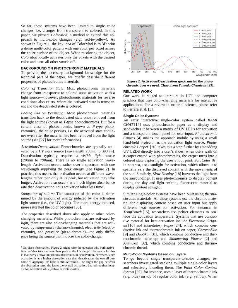
Activation/Deactivation: Photochromics are typically acti-vated by a UV light source (wavelength 250nm to 390nm). Deactivation typically requires a visible light source (390nm to 790nm). There is no single activation wave-length. Activation occurs rather over a spectrum with one wavelength supplying the peak energy (see Figure 2). In practice, this means that activation occurs at different wave-lengths rather than only at its peak, but activation may take longer. Activation also occurs at a much higher absorbance rate than deactivation, thus activation takes less time1.
Saturation of colors: The saturation of the color is deter-mined by the amount of energy induced by the activation light source (i.e., the UV light). The more energy induced, more saturated the color becomes [36].
The properties described above also apply to other color-changing materials: While photochromics are activated by light, there are also color-changing materials that are acti-vated by temperature (thermo-chromic), electricity (electro-chromic), and pressure (piezo-chromic)—the only differ-ence being the source that induces the color-change.
1 On close observation, Figure 2 might raise the question why both activa-tion and deactivation have their peak in the UV range. The reason for this is that every activation process also results in deactivation. However, since activation is at a higher absorption rate than deactivation, the overall out-come of applying UV light is still activation. The larger the gap between the absorption rates, the faster the overall activation, i.e. red requires long-est for activation while yellow activates fastest.
Figure 2. Activation/Deactivation spectrum for the photo-chromic dyes we used. Chart from Yamada Chemicals [29].
RELATED WORK Our work is related to literature in HCI and computer graphics that uses color-changing materials for interactive applications. For a review in material science, please refer to Ferrara et al. [3].
Single Color Systems An early interactive single-color system called KAMI CHAT [14] uses photochromic paper as a display and sandwiches it between a matrix of UV LEDs for activation and a transparent touch panel for user input. Photochromic Canvas [4] makes the approach mobile by using a small hand-held projector as the activation light source. Photo-chromic Carpet ]20 [ takes this a step further by embedding UV LEDS directly into a user’s shoes: when users walk on a carpet coated with photochromics, the carpet turns into a colored state capturing the user’s foot print. SolaColor [6], in contrast, uses sunlight for activation, which allows it to spatially vary the displayed content with the movements of the sun. Similarly, Slow Display [18] harvests the light from the surroundings. It uses photochromics to display content during the day and light-emitting fluorescent material to display content at night.
Similar single-color systems have been built using thermo-chromic materials. All these systems use the chromic mate-rial for displaying content based on user input but apply different heat sources for activation. For instance, in TempTouch [15], researchers use peltier elements to pro-vide the activation temperature. Systems that use conduc-tive material for heat-activation include Electronic Origa-mi [10] and Inkantatory Paper [24], which combine con-ductive ink and thermochromic ink on paper; ChromoSkin [9] and DuoSkin [31], which combine conductive and ther-mochromic make-up; and Shimmering Flower [2] and AnimSkin [32], which combine conductive and thermo-chromic thread.
Multi-Color Systems based on Layers To go beyond single transparent-to-color changes, re-searchers investigated stacking multiple single-color layers and selectively blending them. The Paint Color Control System [25], for instance, uses a layer of thermochromic ink (e.g. blue) on top of regular color ink (e.g. yellow). When
activated with a heat source the blue thermochromic ink becomes visible, thereby blending in with the regular yel-low ink and resulting in different shades of green. Anabio-sis [23] extends this approach by stacking multiple sheets of visible and thermochromic ink: When the user supplies heat by touching the stack, more and more layers become visible as the heat propagates through, resulting in all regular ink layers appearing as a composite image.
Multi-Color Systems based on Pixels Closer to our approach is the idea to use a pattern of multi-ple photochromic color pixels. One such system is Photo-chromic Sculpture [5], which uses a stack of transparent 2D sheets that contain a pattern of painted photochromic pixels. Because the system uses a single light source from the bot-tom, the pixels on each sheet are offset from each other to allow the light to pass through and reach the upper layers. Adding to this, Hirayama et al. [8] contribute the idea to use both - a UV light for activation and a visible-light projector for deactivation. They illustrate this approach by using a silicone sheet manually coated with photochromic dyes. Their vision is to use this approach for a 3D display but no implementation exists till date.
Finally, we share our main motivation with ShaderPrint-er [19], which uses chromic materials for applications in fashion and product design. However, our system provides users with the ability to make multi-color changes.
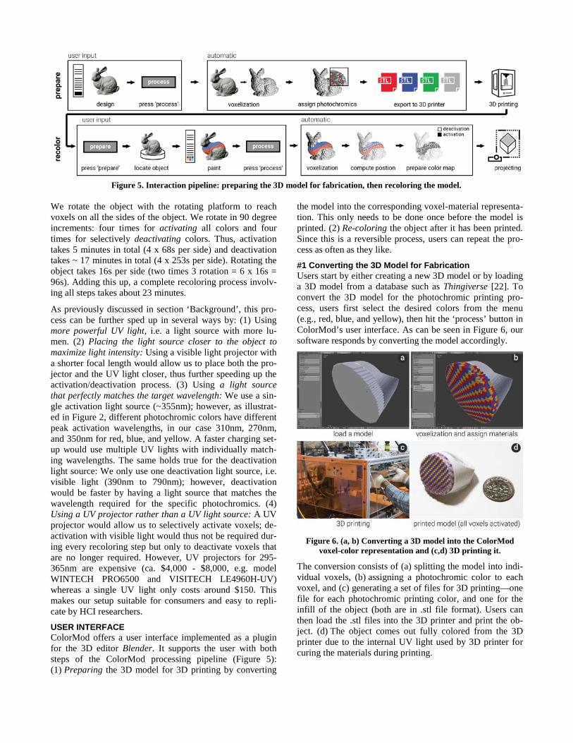
COLORMOD – RECOLORING 3D PRINTED OBJECTS The main contribution of ColorMod is a method to create 3D objects that allow for multi-color changes in their ap-pearance even after fabrication. It works by placing differ-ently colored photochromic materials in a dense multi-color voxel pattern across the entire surface of the object (see Figure 3). During recoloring, only the voxels with the de-sired color are activated; all other voxels remain deactivated and transparent. While the resolution of our 3D printer and projector/camera setup is limited resulting in the color pat-tern to appear coarse, future advances in hardware will like-ly raise the resolution by several orders of magnitude.
Figure 3. A dense pattern of different photochromic voxels
allows for multi-color changes in the same area.
Because painting such a dense multi-color pattern onto the object’s surface by hand is not feasible, we developed a custom 3D printable material based on photochromic dyes (see section ‘Material’). Our material is made from a p-type
photochromic dye; thus color-changes persist even when the object is removed from under the light source.
In the following section, we describe the hardware/software setup behind ColorMod and provide details on the material mixing procedure.
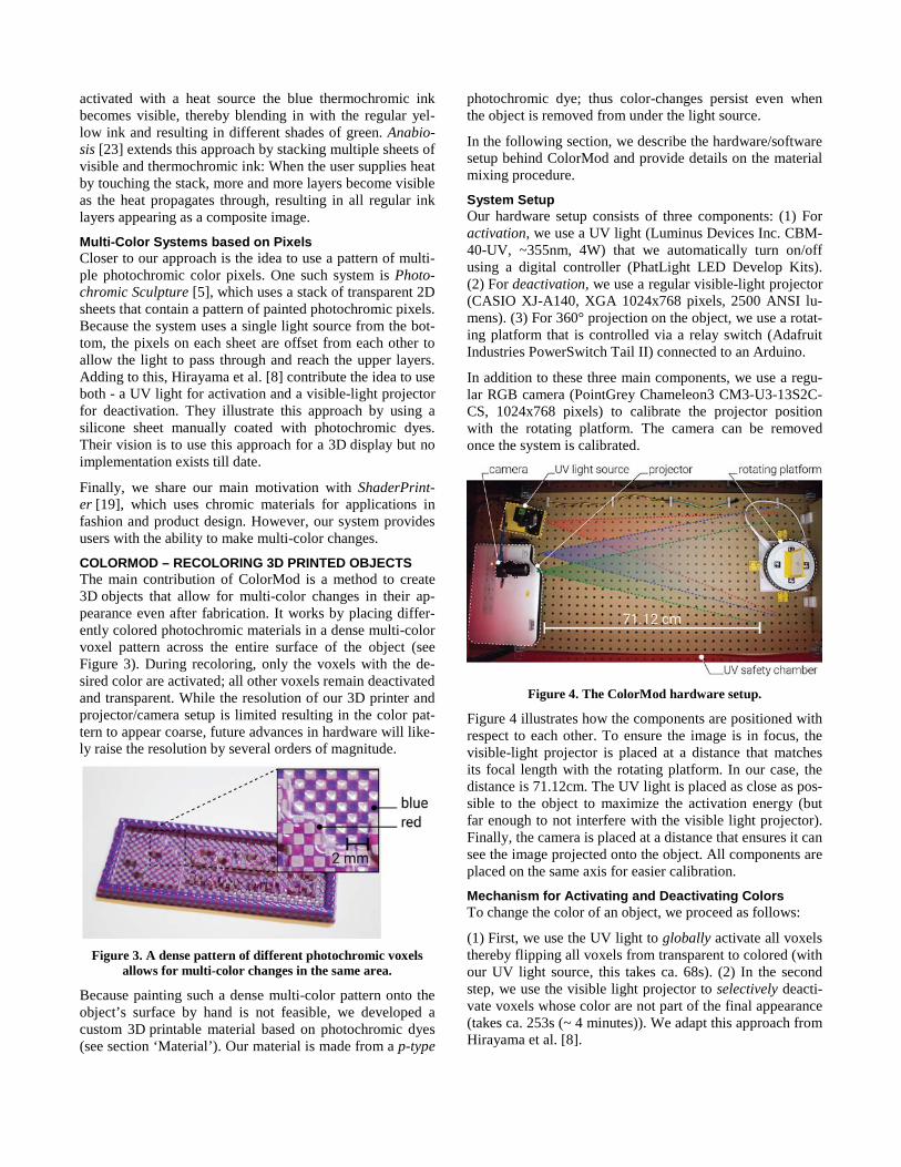
System Setup Our hardware setup consists of three components: (1) For activation, we use a UV light (Luminus Devices Inc. CBM-40-UV, ~355nm, 4W) that we automatically turn on/off using a digital controller (PhatLight LED Develop Kits). (2) For deactivation, we use a regular visible-light projector (CASIO XJ-A140, XGA 1024x768 pixels, 2500 ANSI lu-mens). (3) For 360° projection on the object, we use a rotat-ing platform that is controlled via a relay switch (Adafruit Industries PowerSwitch Tail II) connected to an Arduino.
In addition to these three main components, we use a regu-lar RGB camera (PointGrey Chameleon3 CM3-U3-13S2C-CS, 1024x768 pixels) to calibrate the projector position with the rotating platform. The camera can be removed once the system is calibrated.
Figure 4. The ColorMod hardware setup.
Figure 4 illustrates how the components are positioned with respect to each other. To ensure the image is in focus, the visible-light projector is placed at a distance that matches its focal length with the rotating platform. In our case, the distance is 71.12cm. The UV light is placed as close as pos-sible to the object to maximize the activation energy (but far enough to not interfere with the visible light projector). Finally, the camera is placed at a distance that ensures it can see the image projected onto the object. All components are placed on the same axis for easier calibration.
Mechanism for Activating and Deactivating Colors To change the color of an object, we proceed as follows:
(1) First, we use the UV light to globally activate all voxels thereby flipping all voxels from transparent to colored (with our UV light source, this takes ca. 68s). (2) In the second step, we use the visible light projector to selectively deacti-vate voxels whose color are not part of the final appearance (takes ca. 253s (~ 4 minutes)). We adapt this approach from Hirayama et al. [8].
We rotate the object with the rotating platform to reach voxels on all the sides of the object. We rotate in 90 degree increments: four times for activating all colors and four times for selectively deactivating colors. Thus, activation takes 5 minutes in total (4 x 68s per side) and deactivation takes ~ 17 minutes in total (4 x 253s per side). Rotating the object takes 16s per side (two times 3 rotation = 6 x 16s = 96s). Adding this up, a complete recoloring process involv-ing all steps takes about 23 minutes.
As previously discussed in section ‘Background’, this pro-cess can be further sped up in several ways by: (1) Using more powerful UV light, i.e. a light source with more lu-men. (2) Placing the light source closer to the object to maximize light intensity: Using a visible light projector with a shorter focal length would allow us to place both the pro-jector and the UV light closer, thus further speeding up the activation/deactivation process. (3) Using a light source that perfectly matches the target wavelength: We use a sin-gle activation light source (~355nm); however, as illustrat-ed in Figure 2, different photochromic colors have different peak activation wavelengths, in our case 310nm, 270nm, and 350nm for red, blue, and yellow. A faster charging set-up would use multiple UV lights with individually match-ing wavelengths. The same holds true for the deactivation light source: We only use one deactivation light source, i.e. visible light (390nm to 790nm); however, deactivation would be faster by having a light source that matches the wavelength required for the specific photochromics. (4) Using a UV projector rather than a UV light source: A UV projector would allow us to selectively activate voxels; de-activation with visible light would thus not be required dur-ing every recoloring step but only to deactivate voxels that are no longer required. However, UV projectors for 295-365nm are expensive (ca. $4,000 - $8,000, e.g. model WINTECH PRO6500 and VISITECH LE4960H-UV) whereas a single UV light only costs around $150. This makes our setup suitable for consumers and easy to repli-cate by HCI researchers.
USER INTERFACE ColorMod offers a user interface implemented as a plugin for the 3D editor Blender. It supports the user with both steps of the ColorMod processing pipeline (Figure 5): (1) Preparing the 3D model for 3D printing by converting
the model into the corresponding voxel-material representa-tion. This only needs to be done once before the model is printed. (2) Re-coloring the object after it has been printed. Since this is a reversible process, users can repeat the pro-cess as often as they like.
#1 Converting the 3D Model for Fabrication Users start by either creating a new 3D model or by loading a 3D model from a database such as Thingiverse [22]. To convert the 3D model for the photochromic printing pro-cess, users first select the desired colors from the menu (e.g., red, blue, and yellow), then hit the ‘process’ button in ColorMod’s user interface. As can be seen in Figure 6, our software responds by converting the model accordingly.
Figure 6. (a, b) Converting a 3D model into the ColorMod
voxel-color representation and (c,d) 3D printing it.
The conversion consists of (a) splitting the model into indi-vidual voxels, (b) assigning a photochromic color to each voxel, and (c) generating a set of files for 3D printing—one file for each photochromic printing color, and one for the infill of the object (both are in .stl file format). Users can then load the .stl files into the 3D printer and print the ob-ject. (d) The object comes out fully colored from the 3D printer due to the internal UV light used by 3D printer for curing the materials during printing.
Figure 5. Interaction pipeline: preparing the 3D model for fabrication, then recoloring the model.
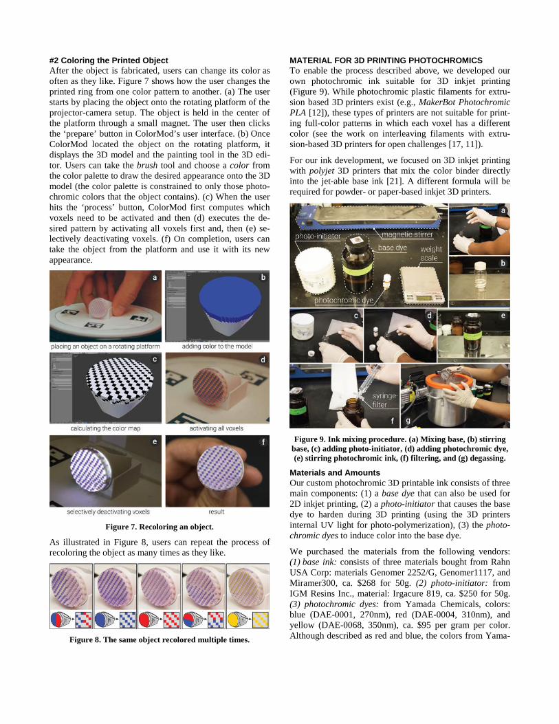
#2 Coloring the Printed Object After the object is fabricated, users can change its color as often as they like. Figure 7 shows how the user changes the printed ring from one color pattern to another. (a) The user starts by placing the object onto the rotating platform of the projector-camera setup. The object is held in the center of the platform through a small magnet. The user then clicks the ‘prepare’ button in ColorMod’s user interface. (b) Once ColorMod located the object on the rotating platform, it displays the 3D model and the painting tool in the 3D edi-tor. Users can take the brush tool and choose a color from the color palette to draw the desired appearance onto the 3D model (the color palette is constrained to only those photo-chromic colors that the object contains). (c) When the user hits the ‘process’ button, ColorMod first computes which voxels need to be activated and then (d) executes the de-sired pattern by activating all voxels first and, then (e) se-lectively deactivating voxels. (f) On completion, users can take the object from the platform and use it with its new appearance.
Figure 7. Recoloring an object.
As illustrated in Figure 8, users can repeat the process of recoloring the object as many times as they like.
Figure 8. The same object recolored multiple times.
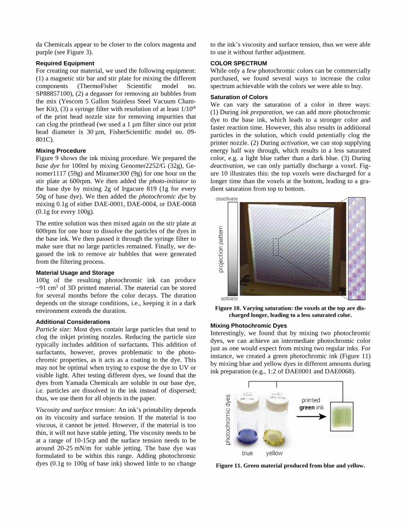
MATERIAL FOR 3D PRINTING PHOTOCHROMICS To enable the process described above, we developed our own photochromic ink suitable for 3D inkjet printing (Figure 9). While photochromic plastic filaments for extru-sion based 3D printers exist (e.g., MakerBot Photochromic PLA [12]), these types of printers are not suitable for print-ing full-color patterns in which each voxel has a different color (see the work on interleaving filaments with extru-sion-based 3D printers for open challenges [17, 11]).
For our ink development, we focused on 3D inkjet printing with polyjet 3D printers that mix the color binder directly into the jet-able base ink [21]. A different formula will be required for powder- or paper-based inkjet 3D printers.
Figure 9. Ink mixing procedure. (a) Mixing base, (b) stirring
base, (c) adding photo-initiator, (d) adding photochromic dye, (e) stirring photochromic ink, (f) filtering, and (g) degassing.
Materials and Amounts Our custom photochromic 3D printable ink consists of three main components: (1) a base dye that can also be used for 2D inkjet printing, (2) a photo-initiator that causes the base dye to harden during 3D printing (using the 3D printers internal UV light for photo-polymerization), (3) the photo-chromic dyes to induce color into the base dye.
We purchased the materials from the following vendors: (1) base ink: consists of three materials bought from Rahn USA Corp: materials Genomer 2252/G, Genomer1117, and Miramer300, ca. $268 for 50g. (2) photo-initiator: from IGM Resins Inc., material: Irgacure 819, ca. $250 for 50g. (3) photochromic dyes: from Yamada Chemicals, colors: blue (DAE-0001, 270nm), red (DAE-0004, 310nm), and yellow (DAE-0068, 350nm), ca. $95 per gram per color. Although described as red and blue, the colors from Yama-
da Chemicals appear to be closer to the colors magenta and purple (see Figure 3).
Required Equipment For creating our material, we used the following equipment: (1) a magnetic stir bar and stir plate for mixing the different components (ThermoFisher Scientific model no. SP88857100), (2) a degasser for removing air bubbles from the mix (Yescom 5 Gallon Stainless Steel Vacuum Cham-ber Kit), (3) a syringe filter with resolution of at least 1/10th of the print head nozzle size for removing impurities that can clog the printhead (we used a 1 µm filter since our print head diameter is 30 µm, FisherScientific model no. 09-801C).
Mixing Procedure Figure 9 shows the ink mixing procedure. We prepared the base dye for 100ml by mixing Genomer2252/G (32g), Ge-nomer1117 (59g) and Miramer300 (9g) for one hour on the stir plate at 600rpm. We then added the photo-initiator to the base dye by mixing 2g of Irgacure 819 (1g for every 50g of base dye). We then added the photochromic dye by mixing 0.1g of either DAE-0001, DAE-0004, or DAE-0068 (0.1g for every 100g).
The entire solution was then mixed again on the stir plate at 600rpm for one hour to dissolve the particles of the dyes in the base ink. We then passed it through the syringe filter to make sure that no large particles remained. Finally, we de-gassed the ink to remove air bubbles that were generated from the filtering process.
Material Usage and Storage 100g of the resulting photochromic ink can produce ~91 cm3 of 3D printed material. The material can be stored for several months before the color decays. The duration depends on the storage conditions, i.e., keeping it in a dark environment extends the duration.
Additional Considerations Particle size: Most dyes contain large particles that tend to clog the inkjet printing nozzles. Reducing the particle size typically includes addition of surfactants. This addition of surfactants, however, proves problematic to the photo-chromic properties, as it acts as a coating to the dye. This may not be optimal when trying to expose the dye to UV or visible light. After testing different dyes, we found that the dyes from Yamada Chemicals are soluble in our base dye, i.e. particles are dissolved in the ink instead of dispersed; thus, we use them for all objects in the paper.
Viscosity and surface tension: An ink’s printability depends on its viscosity and surface tension. If the material is too viscous, it cannot be jetted. However, if the material is too thin, it will not have stable jetting. The viscosity needs to be at a range of 10-15cp and the surface tension needs to be around 20-25 mN/m for stable jetting. The base dye was formulated to be within this range. Adding photochromic dyes (0.1g to 100g of base ink) showed little to no change
to the ink’s viscosity and surface tension, thus we were able to use it without further adjustment.
COLOR SPECTRUM While only a few photochromic colors can be commercially purchased, we found several ways to increase the color spectrum achievable with the colors we were able to buy.
Saturation of Colors We can vary the saturation of a color in three ways: (1) During ink preparation, we can add more photochromic dye to the base ink, which leads to a stronger color and faster reaction time. However, this also results in additional particles in the solution, which could potentially clog the printer nozzle. (2) During activation, we can stop supplying energy half way through, which results in a less saturated color, e.g. a light blue rather than a dark blue. (3) During deactivation, we can only partially discharge a voxel. Fig-ure 10 illustrates this: the top voxels were discharged for a longer time than the voxels at the bottom, leading to a gra-dient saturation from top to bottom.
Figure 10. Varying saturation: the voxels at the top are dis-
charged longer, leading to a less saturated color.
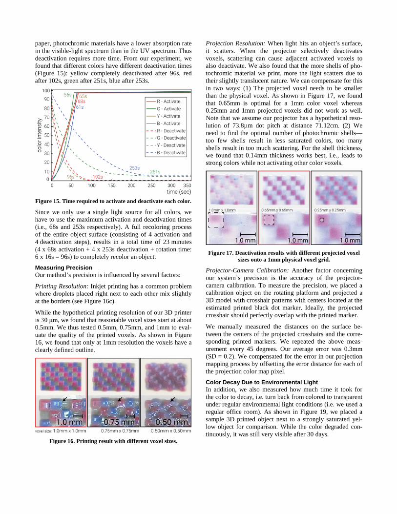
Mixing Photochromic Dyes Interestingly, we found that by mixing two photochromic dyes, we can achieve an intermediate photochromic color just as one would expect from mixing two regular inks. For instance, we created a green photochromic ink (Figure 11) by mixing blue and yellow dyes in different amounts during ink preparation (e.g., 1:2 of DAE0001 and DAE0068).
Figure 11. Green material produced from blue and yellow.

Perceptual Illusion of Additional Colors When multiple colors are printed in a dense pattern, re-search has shown that humans perceive a gradient col-or [28]. While our current system resolution is too low for this perceptual illusion, a future version could increase the range of colors by visually blending them, e.g. blue and red activated close to each other could lead to the perception of a purple voxel.
IMPLEMENTATION In this section, we describe the processing pipeline behind our system. An overview of the whole process is shown in Figure 5. Both 3D model conversion and the painting inter-face are implemented in Python and as a plugin to the 3D editor Blender. We use OpenCV as part of the projector-camera calibration.
3D Printing: Split 3D Model into Multi-Color Voxels We start by converting the 3D model into a high-resolution geometric voxel representations using the algorithm de-scribed in [7]. In short, this algorithm samples, low-pass filters the model into a multi-resolution volume and applies marching cubes [33] for extracting a polygonal mesh and to simplify the voxels. For our setup, the geometric voxel size is approx. 0.05mm x 0.05mm x 0.05mm.
Since only the outer shell of the model is printed with pho-tochromic material and the inside is printed with a regular white material, we need to determine which voxels lay on the outside and which on the inside before assigning mate-rials. A voxel lays on the inside if it has six adjacent voxels (four adjacent voxels on the same layer and one adjacent voxel on each the upper and lower layer). If a voxel has less than six adjacent voxels, it lays on the outside. Figure 12a shows the process of counting adjacent voxels. Since we print multiple shells to achieve a saturated color (see ‘Eval-uation’), we repeat the process until the number of shells equals the desired shell thickness (Figure 12b).
After determining which geometric voxels lay on the out-side and need to be printed with photochromic material, we assign a color to each of these geometric voxels, resulting in what we call a color voxel. We group multiple geometric voxels into a single color voxel as the 3D printing resolu-tion (30 µm) is beyond the handling capacity of our projec-tor.
Figure 12. Determining which voxels lay on the outside and
which on the inside. Only outside voxels have a photochromic color assigned, inside voxels are of regular white material.
A color voxel has one of the colors the user selected from the user interface, in the case of the ring in Figure 8 the colors are red, blue, and yellow. We start at the bottom lay-er and label the voxel as R, B, and Y, respectively (Figure 13a). We then repeat the process along the circumference. Moving up, we offset the colors. Since we group 20 geo-metric voxels into one color voxel, the offset appears every 20 voxels (Figure 13b).
Figure 13. Grouping of geometric voxels to color voxels.
After we assigned a color to each geometric voxel, we ex-port one 3D printable .stl file per color, resulting in three .stl files for the photochromic materials and one .stl file for the white infill material. Each .stl file is then assigned a printing material in the 3D printing software.
3D Painting: Color Map Preparation for Projection After the user places the object on the platform and hits the prepare button, our system loads the projector calibration parameters that was measured in advance into Blender’s virtual camera. The software then prepares the projection viewport and runs the 3D painting tool.
When the user finishes painting the 3D model and hits the ‘process’ button, we match the painted voxels to the photo-chromic color voxels previously assigned to the fabricated object. If in the painted 3D model a color voxel has the same color as in the printed 3D model, we mark it as black. Since black results in no deactivating light from the visible light projector, the corresponding physical voxel will not be deactivated. Otherwise, we mark it as white, i.e. it will be deactivated. Figure 14shows the result of this process: a black/white model (a color map) that we use in the subse-quent deactivation stage (see Figure 7c for a 3D version).
After identifying which voxels need to be deactivated, our software runs a small Arduino script that rotates the plat-form in 90 degree increments. When a specific angle is reached, the matching color-map transfers the digital design onto the physical object by deactivating all voxels of the undesired color.
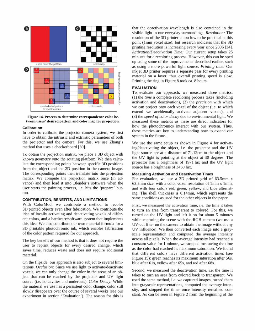
Figure 14. Process to determine correspondence color be-tween users’ desired pattern and color map for projection.
Calibration In order to calibrate the projector-camera system, we first have to obtain the intrinsic and extrinsic parameters of both the projector and the camera. For this, we use Zhang’s method that uses a checkerboard [30].
To obtain the projection matrix, we place a 3D object with known geometry onto the rotating platform. We then calcu-late the corresponding points between specific 3D positions from the object and the 2D position in the camera image. The corresponding points then translate into the projection matrix. We compute the projection matrix once (in ad-vance) and then load it into Blender’s software when the user starts the painting process, i.e. hits the ‘prepare’ but-ton.
CONTRIBUTION, BENEFITS, AND LIMITATIONS With ColorMod, we contribute a method to recolor 3D printed objects even after fabrication. We contribute the idea of locally activating and deactivating voxels of differ-ent colors, and a hardware/software system that implements this idea. We also contribute our own material formula for a 3D printable photochromic ink, which enables fabrication of the color pattern required for our approach.
The key benefit of our method is that it does not require the user to reprint objects for every desired change, which saves time, reduces waste and does not require additional material.
On the flipside, our approach is also subject to several limi-tations. Occlusion: Since we use light to activate/deactivate voxels, we can only change the color in the areas of an ob-ject that can be reached by the projector and UV light source (i.e. no cavities and undercuts). Color Decay: While the material we use has a persistent color change, color still slowly disappears over the course of several weeks (see our experiment in section ‘Evaluation’). The reason for this is
that the deactivation wavelength is also contained in the visible light in our everyday surroundings. Resolution: The resolution of the 3D printer is too low to be practical at this point (1mm voxel size); but research indicates that the 3D printing resolution is increasing every year since 2006 [34]. Activation/Deactivation Time: Our current setup takes 25 minutes for a recoloring process. However, this can be sped up using some of the improvements described earlier, such as using a more powerful light source. Printing time: Our inkjet 3D printer requires a separate pass for every printing material on a layer, thus overall printing speed is slow. Printing the ring in Figure 8 took ca. 8 hours.
EVALUATION To evaluate our approach, we measured three metrics: (1) the time a complete recoloring process takes (including activation and deactivation), (2) the precision with which we can project onto each voxel of the object (i.e. to which extend we accidentally activate adjacent voxels), and (3) the speed of color decay due to environmental light. We measured these metrics as these are direct indicators for how the photochromics interact with our system. Thus, these metrics are key to understanding how to extend our system in the future.
We use the same setup as shown in Figure 4 for activat-ing/deactivating the object, i.e. the projector and the UV light source are at a distance of 71.12cm to the object and the UV light is pointing at the object at 30 degrees. The projector has a brightness of 1971 lux and the UV light source has a brightness of 3460 lux.
Measuring Activation and Deactivation Times For evaluation, we use a 3D printed grid of 63.5mm x 63.5mm size, with a color voxel resolution of 1mm x 1mm, and with four colors red, green, yellow, and blue alternat-ing. The shell thickness is 0.14mm, which represents the same conditions as used for the other objects in the paper.
First, we measured the activation time, i.e. the time it takes to turn an area from transparent to colored. For this, we turned on the UV light and left it on for about 5 minutes while capturing the scene with the RGB camera (we use a UV-cut filter on the camera to obtain the image without any UV influence). We then converted each image into a gray-scale representation and computed the average intensity across all pixels. When the average intensity had reached a constant value for 1 minute, we stopped measuring the time as the color had reached its maximum saturation. We found that different colors have different activation times (see Figure 15): green reaches its maximum saturation after 56s, blue after 61s, yellow after 65s, and red after 68s.
Second, we measured the deactivation time, i.e. the time it takes to turn an area from colored back to transparent. We used the same method, i.e. we captured images, turned them into grayscale representations, computed the average inten-sity, and stopped the timer once intensity remained con-stant. As can be seen in Figure 2 from the beginning of the
paper, photochromic materials have a lower absorption rate in the visible-light spectrum than in the UV spectrum. Thus deactivation requires more time. From our experiment, we found that different colors have different deactivation times (Figure 15): yellow completely deactivated after 96s, red after 102s, green after 251s, blue after 253s.
Figure 15. Time required to activate and deactivate each color.
Since we only use a single light source for all colors, we have to use the maximum activation and deactivation times (i.e., 68s and 253s respectively). A full recoloring process of the entire object surface (consisting of 4 activation and 4 deactivation steps), results in a total time of 23 minutes (4 x 68s activation + 4 x 253s deactivation + rotation time: 6 x 16s = 96s) to completely recolor an object.
Measuring Precision Our method’s precision is influenced by several factors:
Printing Resolution: Inkjet printing has a common problem where droplets placed right next to each other mix slightly at the borders (see Figure 16c).
While the hypothetical printing resolution of our 3D printer is 30 μm, we found that reasonable voxel sizes start at about 0.5mm. We thus tested 0.5mm, 0.75mm, and 1mm to eval-uate the quality of the printed voxels. As shown in Figure 16, we found that only at 1mm resolution the voxels have a clearly defined outline.
Figure 16. Printing result with different voxel sizes.
Projection Resolution: When light hits an object’s surface, it scatters. When the projector selectively deactivates voxels, scattering can cause adjacent activated voxels to also deactivate. We also found that the more shells of pho-tochromic material we print, more the light scatters due to their slightly translucent nature. We can compensate for this in two ways: (1) The projected voxel needs to be smaller than the physical voxel. As shown in Figure 17, we found that 0.65mm is optimal for a 1mm color voxel whereas 0.25mm and 1mm projected voxels did not work as well. Note that we assume our projector has a hypothetical reso-lution of 73.8µm dot pitch at distance 71.12cm. (2) We need to find the optimal number of photochromic shells—too few shells result in less saturated colors, too many shells result in too much scattering. For the shell thickness, we found that 0.14mm thickness works best, i.e., leads to strong colors while not activating other color voxels.
Figure 17. Deactivation results with different projected voxel
sizes onto a 1mm physical voxel grid.
Projector-Camera Calibration: Another factor concerning our system’s precision is the accuracy of the projector-camera calibration. To measure the precision, we placed a calibration object on the rotating platform and projected a 3D model with crosshair patterns with centers located at the estimated printed black dot marker. Ideally, the projected crosshair should perfectly overlap with the printed marker.
We manually measured the distances on the surface be-tween the centers of the projected crosshairs and the corre-sponding printed markers. We repeated the above meas-urement every 45 degrees. Our average error was 0.3mm (SD = 0.2). We compensated for the error in our projection mapping process by offsetting the error distance for each of the projection color map pixel.
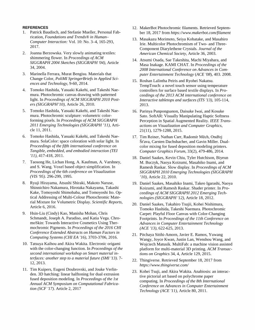
Color Decay Due to Environmental Light In addition, we also measured how much time it took for the color to decay, i.e. turn back from colored to transparent under regular environmental light conditions (i.e. we used a regular office room). As shown in Figure 19, we placed a sample 3D printed object next to a strongly saturated yel-low object for comparison. While the color degraded con-tinuously, it was still very visible after 30 days.
To speed up the de-coloration process, we tripled the light intensity by using a white desktop light with three times as many lumen as we measured in the room (810 lux com-pared to the 270 lux in our room). We left the object under the light for another 20 days, simulating day 35-90 as de-picted in Figure 19 (i.e. day 90 is 30 days of 270 lux + 20 days of triple light intensity, i.e. 810 lux). We found that the color of the object completely degraded after approx. 90 simulated days.
Figure 19. Color decay of photochromics caused by light from
the environment.
APPLICATION SCENARIOS We envision the following application scenarios for our approach of recoloring objects:
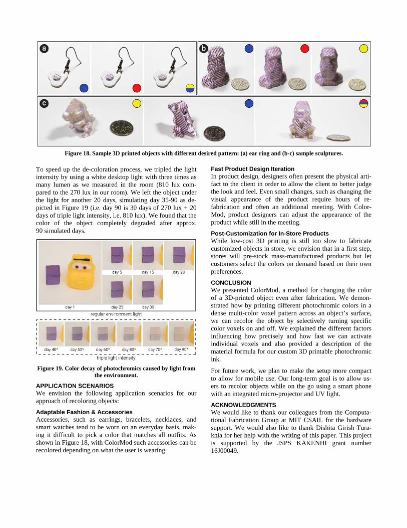
Adaptable Fashion & Accessories Accessories, such as earrings, bracelets, necklaces, and smart watches tend to be worn on an everyday basis, mak-ing it difficult to pick a color that matches all outfits. As shown in Figure 18, with ColorMod such accessories can be recolored depending on what the user is wearing.
Fast Product Design Iteration In product design, designers often present the physical arti-fact to the client in order to allow the client to better judge the look and feel. Even small changes, such as changing the visual appearance of the product require hours of re-fabrication and often an additional meeting. With Color-Mod, product designers can adjust the appearance of the product while still in the meeting.
Post-Customization for In-Store Products While low-cost 3D printing is still too slow to fabricate customized objects in store, we envision that in a first step, stores will pre-stock mass-manufactured products but let customers select the colors on demand based on their own preferences.
CONCLUSION We presented ColorMod, a method for changing the color of a 3D-printed object even after fabrication. We demon-strated how by printing different photochromic colors in a dense multi-color voxel pattern across an object’s surface, we can recolor the object by selectively turning specific color voxels on and off. We explained the different factors influencing how precisely and how fast we can activate individual voxels and also provided a description of the material formula for our custom 3D printable photochromic ink.
For future work, we plan to make the setup more compact to allow for mobile use. Our long-term goal is to allow us-ers to recolor objects while on the go using a smart phone with an integrated micro-projector and UV light.
ACKNOWLEDGMENTS We would like to thank our colleagues from the Computa-tional Fabrication Group at MIT CSAIL for the hardware support. We would also like to thank Dishita Girish Tura-khia for her help with the writing of this paper. This project is supported by the JSPS KAKENHI grant number 16J00049.
Figure 18. Sample 3D printed objects with different desired pattern: (a) ear ring and (b-c) sample sculptures.
REFERENCES 1. Patrick Baudisch, and Stefanie Mueller, Personal Fab-
rication, Foundations and Trends® in Human–Computer Interaction: Vol. 10: No. 3–4, 165-293, 2017.
2. Joanna Berzowska. Very slowly animating textiles: shimmering flower. In Proceedings of ACM SIGGRAPH 2004 Sketches (SIGGRAPH '04), Article 34, 2004.
3. Marinella Ferrara, Murat Bengisu. Materials that Change Color, PoliMI SpringerBriefs in Applied Sci-ences and Technology, 9-60, 2014.
4. Tomoko Hashida, Yasuaki Kakehi, and Takeshi Nae-mura. Photochromic canvas drawing with patterned light. In Proceedings of ACM SIGGRAPH 2010 Post-ers (SIGGRAPH’10), Article 26, 2010.
5. Tomoko Hashida, Yasuaki Kakehi, and Takeshi Nae-mura. Photochromic sculpture: volumetric color-forming pixels. In Proceedings of ACM SIGGRAPH 2011 Emerging Technologies (SIGGRAPH ’11), Arti-cle 11, 2011.
6. Tomoko Hashida, Yasuaki Kakehi, and Takeshi Nae-mura. SolaColor: space coloration with solar light. In Proceedings of the fifth international conference on Tangible, embedded, and embodied interaction (TEI '11), 417-418, 2011.
7. Taosong He, Lichan Hong, A. Kaufman, A. Varshney, and S. Wang. Voxel based object simplification. In Proceedings of the 6th conference on Visualization (VIS '95). 296-299, 1995.
8. Ryuji Hirayama, Atsushi Shiraki, Makoto Naruse, Shinnichiro Nakamura, Hirotaka Nakayama, Takashi Kake, Tomoyoshi Shimobaba, and Tomoyoshi Ito. Op-tical Addressing of Multi-Colour Photochromic Mate-rial Mixture for Volumetric Display. Scientific Reports, Article 6, 2016.
9. Hsin-Liu (Cindy) Kao, Manisha Mohan, Chris Schmandt, Joseph A. Paradiso, and Katia Vega. Chro-moSkin: Towards Interactive Cosmetics Using Ther-mochromic Pigments. In Proceedings of the 2016 CHI Conference Extended Abstracts on Human Factors in Computing Systems (CHI EA '16), 3703-3706, 2016.
10. Tatsuya Kaihou and Akira Wakita. Electronic origami with the color-changing function. In Proceedings of the second international workshop on Smart material in-terfaces: another step to a material future (SMI '13). 7-12, 2013.
11. Tim Kuipers, Eugeni Doubrovski, and Jouke Verlin-den. 3D hatching: linear halftoning for dual extrusion fused deposition modeling. In Proceedings of the 1st Annual ACM Symposium on Computational Fabrica-tion (SCF '17). Article 2, 2017
12. MakerBot Photochromic filaments. Retrieved Septem-ber 18, 2017 from https://www.makerbot.com/filament
13. Masakazu Morimoto, Seiya Kobatake, and Masahiro Irie. Multicolor Photochromism of Two- and Three-Component Diarylethene Crystals. Journal of the American Chemical Society, Article 36, 2003.
14. Atsumi Osada, Sae Takeshita, Machi Miyahara, and Masa Inakage. KAMI CHAT. In Proceedings of the 2008 International Conference on Advances in Com-puter Entertainment Technology (ACE '08), 403. 2008.
15. Roshan Lalintha Peiris and Ryohei Nakatsu. TempTouch: a novel touch sensor using temperature controllers for surface based textile displays. In Pro-ceedings of the 2013 ACM international conference on Interactive tabletops and surfaces (ITS '13), 105-114, 2013.
16. Parinya Punpongsanon, Daisuke Iwai, and Kosuke Sato. SoftAR: Visually Manipulating Haptic Softness Perception in Spatial Augmented Reality. IEEE Trans-actions on Visualization and Computer Graphics, 21(11), 1279-1288, 2015.
17. Tim Reiner, Nathan Carr, Radomír Měch, Ondřej Št'ava, Carsten Dachsbacher, and Gavin Miller. Dual-color mixing for fused deposition modeling printers. Computer Graphics Forum, 33(2), 479-486, 2014.
18. Daniel Saakes, Kevin Chiu, Tyler Hutchison, Biyeun M. Buczyk, Naoya Koizumi, Masahiko Inami, and Ramesh Raskar. Slow display. In Proceedings of ACM SIGGRAPH 2010 Emerging Technologies (SIGGRAPH ’10), Article 22, 2010.
19. Daniel Saakes, Masahiko Inami, Takeo Igarashi, Naoya Koizumi, and Ramesh Raskar. Shader printer. In Pro-ceedings of ACM SIGGRAPH 2012 Emerging Tech-nologies (SIGGRAPH '12), Article 18, 2012.
20. Daniel Saakes, Takahiro Tsujii, Kohei Nishimura, Tomoko Hashida, Takeshi Naemura. Photochromic Carpet: Playful Floor Canvas with Color-Changing Footprints. In Proceedings of the 11th Conference on Advances in Computer Entertainment Technology (ACE '13), 622-625, 2013.
21. Pitchaya Sitthi-Amorn, Javier E. Ramos, Yuwang Wangy, Joyce Kwan, Justin Lan, Wenshou Wang, and Wojciech Matusik. MultiFab: a machine vision assisted platform for multi-material 3D printing. ACM Transac-tions on Graphics 34, 4, Article 129, 2015.
22. Thingiverse. Retrieved September 18, 2017 from https://www.thingiverse.com/
23. Kohei Tsuji, and Akira Wakita. Anabiosis: an interac-tive pictorial art based on polychrome paper computing. In Proceedings of the 8th International Conference on Advances in Computer Entertainment Technology (ACE '11), Article 80, 2011.
24. Takahiro Tsujii, Koizumi Naoya, and Takeshi Naemu-ra. Inkantatory Paper: Dynamically Color-changing Prints with Multiple Functional Inks. In Proceedings of the 27th Annual Symposium on User Interface Software and Technology (UIST’14), 39-40, 2014.
25. Hiroki Yamada, Tomohiro Tanikawa, Kunihiro Nishi-mura, and Michitaka Hirose. Paint color control system with infrared photothermal conversion. In Proceedings of the 8th International Conference on Advances in Computer Entertainment Technology (ACE '11), Arti-cle 64, 2011.
26. Yi Zhou, Shuangjiu Xiao, Ning Tang, Zhiyong Wei, and Xu Chen. Pmomo: Projection Mapping on Mova-ble 3D Object. In Proceedings of the 2016 CHI Con-ference on Human Factors in Computing Systems (CHI '16), 781-790, 2016.
27. Andrew Towns. Colorant, Photochromic. Encyclopedia of Color Science and Technology, Springer Sci-ence+Business Media. 447-455, 2016.
28. Brian A. Wandell. Foundations of Vision. Sinauer As-sociates, 1995.
29. Yamada Chemicals. Retrieved December 19, 2017 from http://ymdchem.com/
30. Zhengyou Zhang. A Flexible New Technique for Cam-era Calibration. IEEE Transactions on pattern analysis and machine intelligence, 22(11), 1330-1334, 2000.
31. Hsin-Liu (Cindy) Kao, Christian Holz, Asta Roseway, Andres Calvo, and Chris Schmandt. DuoSkin: rapidly
prototyping on-skin user interfaces using skin-friendly materials. In Proceedings of the 2016 ACM Interna-tional Symposium on Wearable Computers (ISWC '16), 16-23, 2016.
32. Yanan Wang, Shijian Luo, Yujia Lu, Hebo Gong, Yex-ing Zhou, Shuai Liu, and Preben Hansen. AnimSkin: Fabricating Epidermis with Interactive, Functional and Aesthetic Color Animation. In Proceedings of the 2017 Conference on Designing Interactive Systems (DIS '17), 397-401, 2017.
33. William E. Lorensen and Harvey E. Cline. Marching cubes: A high resolution 3D surface construction algo-rithm. In Proceedings of the 14th annual conference on Computer graphics and interactive techniques (SIGGRAPH '87), 163-169, 1987.
34. Ariel Calderon, James Griffin, and Juan Cristóbal Za-gal. BeamMaker: an open hardware high-resolution digital fabricator for the masses. Rapid Prototyping Journal, 20(3), 245-255, 2014.
35. Parinya Punpongsanon, Daisuke Iwai, and Kosuke Sato. Projection-based visualization of tangential de-formation of Nonrigid surface by deformation estima-tion using infrared texture. Virtual Reality, 19(1), 45-56, 2015.
36. Shoichi Takeda, Daisuke Iwai, and Kosuke Sato. Inter-reflection Compensation of Immersive Projection Dis-play by Spatio-Temporal Screen Reflectance Modula-tion. IEEE Transactions on Visualization and Comput-er Graphics, 22(4), 1424-1431, 2016.
Related Documents