Color-rendering of Daylight from Water-filled Light Pipes Authors Ross McCluney, Ph.D. Original Publication McCluney, Ross, "Color-rendering of Daylight from Water-filled Light Pipes", Reprinted from Solar Energy Materials 21 (1990) 191-206. Publication Number FSEC-PF-423-90 Copyright Copyright © Florida Solar Energy Center/University of Central Florida 1679 Clearlake Road, Cocoa, Florida 32922, USA (321) 638-1000 All rights reserved. Disclaimer The Florida Solar Energy Center/University of Central Florida nor any agency thereof, nor any of their employees, makes any warranty, express or implied, or assumes any legal liability or responsibility for the accuracy, completeness, or usefulness of any information, apparatus, product, or process disclosed, or represents that its use would not infringe privately owned rights. Reference herein to any specific commercial product, process, or service by trade name, trademark, manufacturer, or otherwise does not necessarily constitute or imply its endorsement, recommendation, or favoring by the Florida Solar Energy Center/University of Central Florida or any agency thereof. The views and opinions of authors expressed herein do not necessarily state or reflect those of the Florida Solar Energy Center/University of Central Florida or any agency thereof.

Welcome message from author
This document is posted to help you gain knowledge. Please leave a comment to let me know what you think about it! Share it to your friends and learn new things together.
Transcript
Color-rendering of Daylight from Water-filled Light Pipes
Authors Ross McCluney, Ph.D.
Original Publication
McCluney, Ross, "Color-rendering of Daylight from Water-filled Light Pipes", Reprinted from Solar Energy Materials 21 (1990) 191-206.
Publication Number FSEC-PF-423-90
Copyright
Copyright © Florida Solar Energy Center/University of Central Florida 1679 Clearlake Road, Cocoa, Florida 32922, USA
(321) 638-1000 All rights reserved.
Disclaimer
The Florida Solar Energy Center/University of Central Florida nor any agency thereof, nor any of their employees, makes any warranty, express or implied, or assumes any legal liability or responsibility for the accuracy, completeness, or usefulness of any information, apparatus, product, or process disclosed, or represents that its use would not infringe privately owned rights. Reference herein to any specific commercial product, process, or service by trade name, trademark, manufacturer, or otherwise does not necessarily constitute or imply its endorsement, recommendation, or favoring by the Florida Solar Energy Center/University of Central Florida or any agency thereof. The views and opinions of authors expressed herein do not necessarily state or reflect those of the Florida Solar Energy Center/University of Central Florida or any agency thereof.
Reprinted from Solar Energy Materials 21 (1990) 191-206.
Color-rendering of Daylight from Water-filled Light Pipes
Ross McCluneyFlorida Solar Energy Center
300 State Road 401Cape Canaveral, FL 32920
Abstract
Water-filled light pipes can be used to transport concentrated beam solar radiation from a solarcollection system to a utilization system, altering the spectral distribution of the radiation in abeneficial way in the process. One use for such a system would be for the daylighting of the coreinterior spaces of buildings, spaces that are far removed from outside walls or the roof and aretherefore not amenable to conventional daylighting with sidelights or toplights. The filtering actionof the water can be used to remove unwanted infrared and ultraviolet radiation while affecting thevisible portion of the radiation only slightly. There are limits, however, to the distance such lightcan be propagated in water without undesirable color shifts. Comparing with warm whitefluorescent light this distance appears to be about 6 to 8 meters. Comparing it to daylight, thedistance extends to about 10 to 12 meters. The distance for a significant drop in the color-renderingindex is approximately 10 meters. Filters can be added to the light pipe to partially compensate forunwnated color shifts and to extend the maximum distance for transfer, but substantial transmissionlosses are thereby incurred. Due to these limits, it is suggested that the most likely use of such lightpipes would be in a hybrid water/air system, where the water-filled portion of the light pipes wouldbe of limited length and would be used primarily for infrared heat removal. It is possible thatseparate color-correcting filters can be replaced by appropriately selected dyes added to the water.Another possible use for a version of the water-filled light pipe is for spectral shaping and heatremoval in concentrating PV solar energy conversion systems.
Introduction
The daylighting of the interior spaces of buildings provides many benefits [1], including energysavings [2], visual connections with the outdoors (and the psychological benefits derivingtherefrom), and good quality, healthy illumination to promote worker productivity [3]. For thesebenefits to be realized, however, the design of the building must be carefully executed [4] and theproblems that can result from improperly placed and shaded fenestration apertures must be dealtwith in all stages of the design process [5].
Traditional approaches to daylighting design deal mainly with the perimeter spaces of buildings,leaving the core areas wholly to electric lighting. Several proposals have been made, however, for collecting daylight outside a building and directing or piping it to the interior or core spaces farremoved from the perimeter areas [6].
Water-filled light pipes have been proposed for transporting solar direct-beam illumination fromconcentrating collectors to the cores of habitable spaces [7]. However, water has a nonuniform
2
(1)
(2)
(3)
transmittance over the visible portion of the spectrum. Thus, its use as a transport medium willimpart a color to the light emerging from the end of the light pipe, as well as an attenuation of theflux passing through the pipe. Countering this is the advantage that by stripping the incident solarradiation of its infrared component, water-filled light pipes can deliver light of high luminousefficacy (ratio of light flux in Lumens to total radiant flux in Watts) to the illuminated space. Theheat load on the space cooling system is therby reduced, conserving energy and contributing toenhanced human comfort. The heat removed can even be used for other purposes inside thebuilding, notably for pre-heating domestic hot water.
The purposes of this paper are to describe these effects, provide estimates of the maximum distancessolar radiation can be so piped without imparting unacceptable color, and discuss the limits of theuse of possible color-correcting filters inserted into the emerging beam.
Problems of attenuation at water-to-air and water-to-solid interfaces, of particulate scattering effects,and the effects of impurities in the water are not addressed. The intent is to determine fundamentallimits to the usefulness of the concept, using optimistic but not unreasonable assumptions, not toexplore its overall technical feasibility.
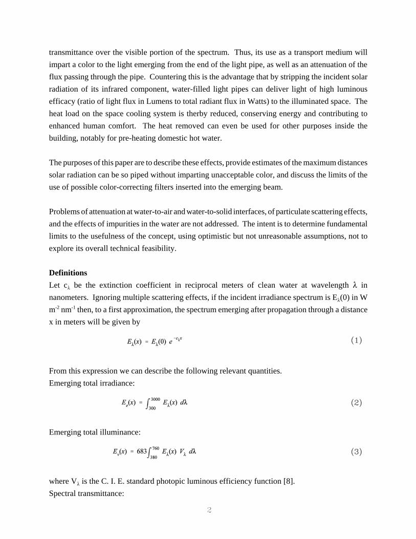
DefinitionsLet c8 be the extinction coefficient in reciprocal meters of clean water at wavelength 8 innanometers. Ignoring multiple scattering effects, if the incident irradiance spectrum is E8(0) in Wm-2 nm-1 then, to a first approximation, the spectrum emerging after propagation through a distancex in meters will be given by
From this expression we can describe the following relevant quantities.Emerging total irradiance:
Emerging total illuminance:
where V8 is the C. I. E. standard photopic luminous efficiency function [8].Spectral transmittance:
3
(4)
(5)
(6)
(7)
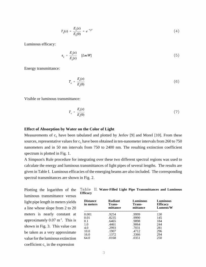
Distance Radiant Luminous Luminousin meters Trans- Trans- Efficacy
mittance mittance Lumens/W))))))))))))))))))))))))))))))))))))))Q0.001 .9254 .9999 1300.01 .8235 .9990 1450.1 .6465 .9898 1841.0 .4461 .9064 2444.0 .2993 .7031 28110.0 .1907 .4712 29616.0 .1372 .3366 29464.0 .0168 .0351 250
Table II. Water-Filled Light Pipe Transmittances and LuminousEfficacy
Luminous efficacy:
Energy transmittance:
Visible or luminous transmittance:
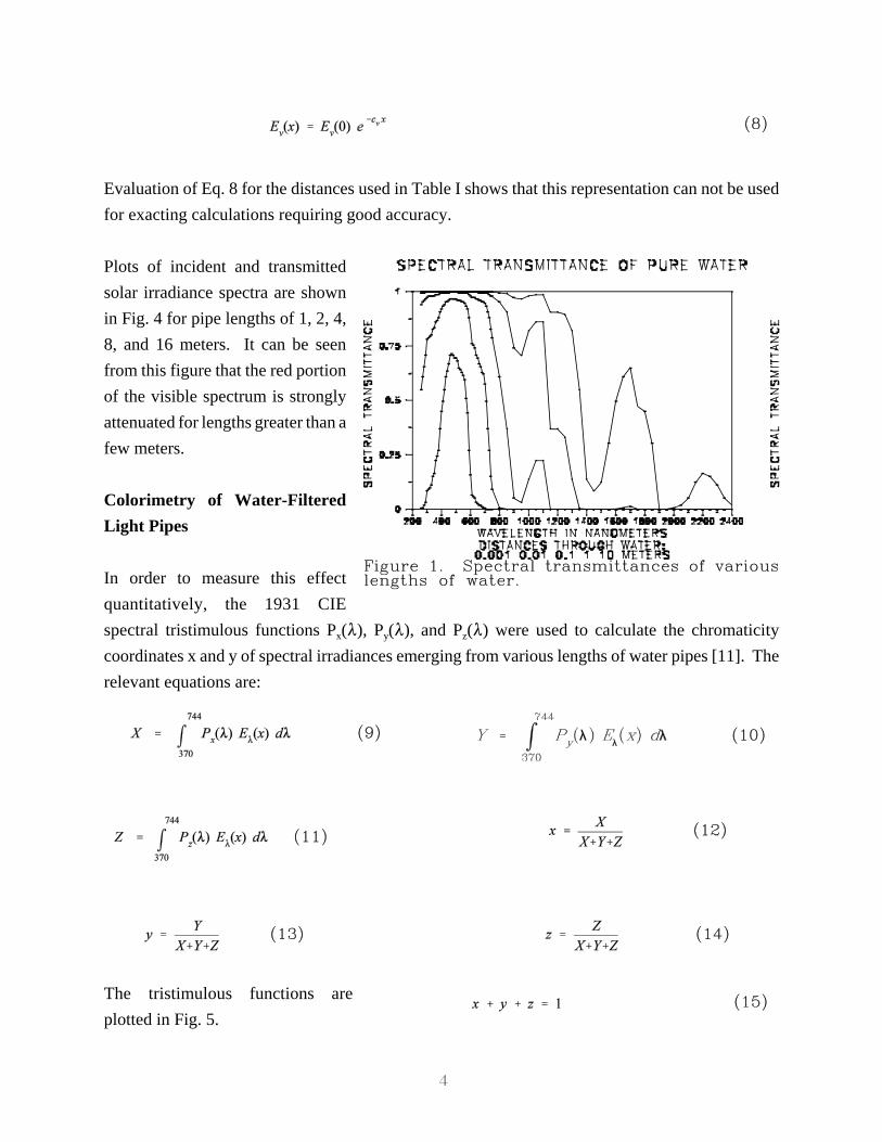
Effect of Absorption by Water on the Color of LightMeasurements of c8 have been tabulated and plotted by Jerlov [9] and Morel [10]. From thesesources, representative values for c8 have been obtained in ten-nanometer intervals from 260 to 750nanometers and in 50 nm intervals from 750 to 2400 nm. The resulting extinction coefficientspectrum is plotted in Fig. 1.A Simpson's Rule procedure for integrating over these two different spectral regions was used tocalculate the energy and luminous transmittances of light pipes of several lengths. The results aregiven in Table I. Luminous efficacies of the emerging beams are also included. The correspondingspectral transmittances are shown in Fig. 2.
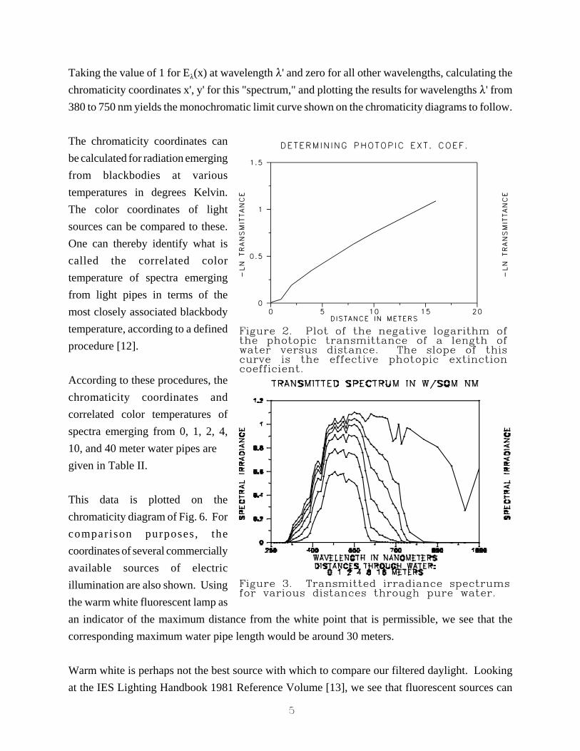
Plotting the logarithm of theluminous transmittance versuslight pipe length in meters yieldsa line whose slope from 2 to 20meters is nearly constant atapproximately 0.07 m-1. This isshown in Fig. 3. This value canbe taken as a very approximatevalue for the luminous extinctioncoefficient cv in the expression
4
(8)
Figure 1. Spectral transmittances of variouslengths of water.
(9) (10)
(11) (12)
(13) (14)
(15)
Evaluation of Eq. 8 for the distances used in Table I shows that this representation can not be usedfor exacting calculations requiring good accuracy.
Plots of incident and transmittedsolar irradiance spectra are shownin Fig. 4 for pipe lengths of 1, 2, 4,8, and 16 meters. It can be seenfrom this figure that the red portionof the visible spectrum is stronglyattenuated for lengths greater than afew meters.
Colorimetry of Water-FilteredLight Pipes
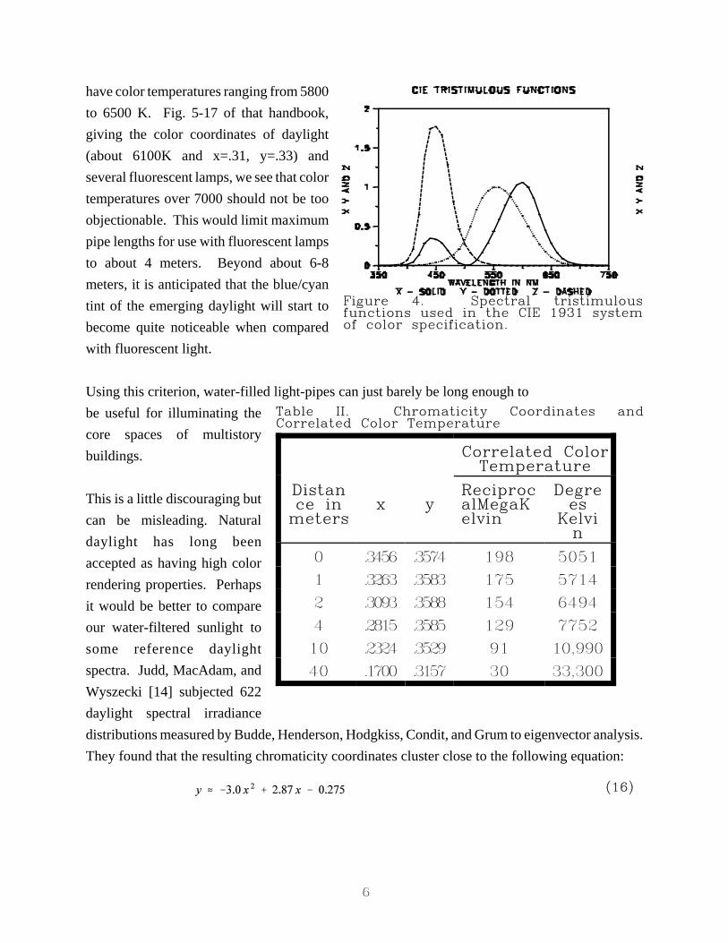
In order to measure this effectquantitatively, the 1931 CIEspectral tristimulous functions Px(8), Py(8), and Pz(8) were used to calculate the chromaticitycoordinates x and y of spectral irradiances emerging from various lengths of water pipes [11]. Therelevant equations are:
The tristimulous functions areplotted in Fig. 5.
5
Figure 2. Plot of the negative logarithm ofthe photopic transmittance of a length ofwater versus distance. The slope of thiscurve is the effective photopic extinctioncoefficient.
Figure 3. Transmitted irradiance spectrumsfor various distances through pure water.
Taking the value of 1 for E8(x) at wavelength 8' and zero for all other wavelengths, calculating thechromaticity coordinates x', y' for this "spectrum," and plotting the results for wavelengths 8' from380 to 750 nm yields the monochromatic limit curve shown on the chromaticity diagrams to follow.
The chromaticity coordinates canbe calculated for radiation emergingfrom blackbodies at varioustemperatures in degrees Kelvin.The color coordinates of lightsources can be compared to these.One can thereby identify what iscalled the correlated colortemperature of spectra emergingfrom light pipes in terms of themost closely associated blackbodytemperature, according to a definedprocedure [12].
According to these procedures, thechromaticity coordinates andcorrelated color temperatures ofspectra emerging from 0, 1, 2, 4,10, and 40 meter water pipes are given in Table II.
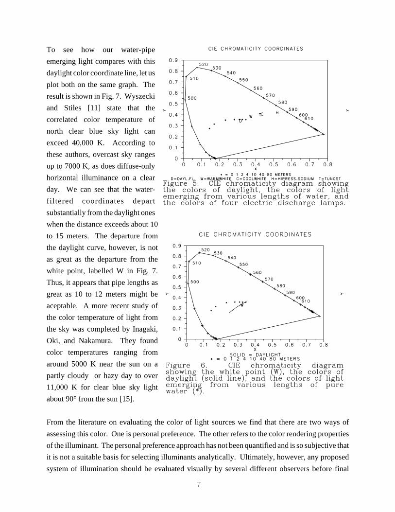
This data is plotted on thechromaticity diagram of Fig. 6. Forcomparison purposes , thecoordinates of several commerciallyavailable sources of electricillumination are also shown. Usingthe warm white fluorescent lamp asan indicator of the maximum distance from the white point that is permissible, we see that thecorresponding maximum water pipe length would be around 30 meters.
Warm white is perhaps not the best source with which to compare our filtered daylight. Lookingat the IES Lighting Handbook 1981 Reference Volume [13], we see that fluorescent sources can
6
Figure 4. Spectral tristimulousfunctions used in the CIE 1931 systemof color specification.
Correlated ColorTemperature
Distance inmeters
x yReciprocalMegaKelvin
Degrees
Kelvin
0 .3456 .3574 198 5051
1 .3263 .3583 175 5714
2 .3093 .3588 154 6494
4 .2815 .3585 129 7752
10 .2324 .3529 91 10,990
40 .1700 .3157 30 33,300
Table II. Chromaticity Coordinates andCorrelated Color Temperature
(16)
have color temperatures ranging from 5800to 6500 K. Fig. 5-17 of that handbook,giving the color coordinates of daylight(about 6100K and x=.31, y=.33) andseveral fluorescent lamps, we see that colortemperatures over 7000 should not be tooobjectionable. This would limit maximumpipe lengths for use with fluorescent lampsto about 4 meters. Beyond about 6-8meters, it is anticipated that the blue/cyantint of the emerging daylight will start tobecome quite noticeable when comparedwith fluorescent light.
Using this criterion, water-filled light-pipes can just barely be long enough tobe useful for illuminating thecore spaces of multistorybuildings.
This is a little discouraging butcan be misleading. Naturaldaylight has long beenaccepted as having high colorrendering properties. Perhapsit would be better to compareour water-filtered sunlight tosome reference daylightspectra. Judd, MacAdam, andWyszecki [14] subjected 622daylight spectral irradiancedistributions measured by Budde, Henderson, Hodgkiss, Condit, and Grum to eigenvector analysis.They found that the resulting chromaticity coordinates cluster close to the following equation:
7
Figure 5. CIE chromaticity diagram showingthe colors of daylight, the colors of lightemerging from various lengths of water, andthe colors of four electric discharge lamps.
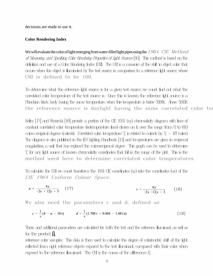
Figure 6. CIE chromaticity diagramshowing the white point (W), the colors ofdaylight (solid line), and the colors of lightemerging from various lengths of purewater (*).
To see how our water-pipeemerging light compares with thisdaylight color coordinate line, let usplot both on the same graph. Theresult is shown in Fig. 7. Wyszeckiand Stiles [11] state that thecorrelated color temperature ofnorth clear blue sky light canexceed 40,000 K. According tothese authors, overcast sky rangesup to 7000 K, as does diffuse-onlyhorizontal illuminance on a clearday. We can see that the water-filtered coordinates departsubstantially from the daylight oneswhen the distance exceeds about 10to 15 meters. The departure fromthe daylight curve, however, is notas great as the departure from thewhite point, labelled W in Fig. 7.Thus, it appears that pipe lengths asgreat as 10 to 12 meters might beaceptable. A more recent study ofthe color temperature of light fromthe sky was completed by Inagaki,Oki, and Nakamura. They foundcolor temperatures ranging fromaround 5000 K near the sun on apartly cloudy or hazy day to over11,000 K for clear blue sky lightabout 90° from the sun [15].
From the literature on evaluating the color of light sources we find that there are two ways ofassessing this color. One is personal preference. The other refers to the color rendering propertiesof the illuminant. The personal preference approach has not been quantified and is so subjective thatit is not a suitable basis for selecting illuminants analytically. Ultimately, however, any proposedsystem of illumination should be evaluated visually by several different observers before final
8
(17) (18)
(19)
decisions are made to use it.
Color Rendering Index
We will evaluate the color of light emerging from water-filled light pipes using the 1964 CIE Methodof Measuring and Specifying Color Rendering Properties of Light Sources [16]. This method is based on thedefinition and use of a Color Rendering Index (CRI). The CRI is a measure of the shift in object color thatoccurs when the object is illuminated by the test source, in comparison to a reference light source, whoseCRI is defined to be 100.
To determine what the reference light source is for a given test source, we must find out what thecorrelated color temperature of the test source is. Once this is known, the reference light source is aPlanckian black body having the same temperature, when this temperature is below 5000K. Above 5000Kthe reference source is daylight having the same correlated color tem
Kelley [17] and Wyszecki [18] provide a portion of the CIE 1931 (x,y) chromaticity diagram with lines ofconstant correlated color temperature (isotemperature lines) drawn on it, over the range from 0 to 660micro reciprical degrees (mireds). Correlated color temperature Tc is related to mireds by: Tc = 10
6/mired.The diagram is also published in the IES Lighting Handbook [13] and temperatures are given in reciprocalmegakelvins, a unit that has replaced the microreciprocal degree. This graph can be used to determineTc for any light source of known chromaticity coordinates that fall in the range of the plot. This is themethod used here to determine correlated color temperatures.
To calculate the CRI we must transform the 1931 CIE coordinates (x,y) into the coordinates (u,v) of theCIE 1964 Uniform Colour Space:
We also need the parameters c and d, defined as
These, and additional parameters, are calculated for both the test and the reference illuminant, as well asfor the product $8ireference color samples. This data is then used to calculate the degree of colorimetric shift of the lightreflected from eight reference objects exposed to the test illuminant, compared with their color whenexposed to the reference illuminant. The CRI is the mean of the differences Ri
9
(20)
CORRELATED SOURCE COLOR TEMP
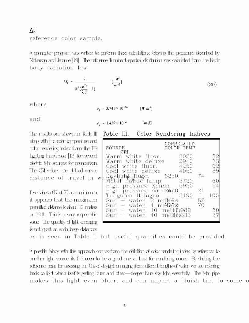
CRIWarm white fluor. 3020 52Warm white deluxe 2940 73Cool white fluor. 4250 62Cool white deluxe 4050 89Daylight fluor. 6250 74Metal halide lamp 3720 60High pressure Xenon 5920 94High pressure sodium 2100 21Tungsten Halogen 3190 100Sun + water, 2 meters 6494 82Sun + water, 4 meters 7752 70Sun + water, 10 meters 10,989 50Sun + water, 40 meters 33,333 37
Table III. Color Rendering Indices
)Kireference color sample.
A computer program was written to perform these calculations, following the procedure described byNickerson and Jerome [19]. The reference illuminant spectral distribution was calculated from the blackbody radiation law:
where
and
The results are shown in Table III,along with the color temperature andcolor rendering index from the IESLighting Handbook [13] for severalelectric light sources for comparison.The CRI values are plotted versusdistance of travel in water in Fig. 8.
If we take a CRI of 50 as a minimum,it appears that the maximumpermitted distance is about 10 metersor 33 ft. This is a very respectablevalue. The quantity of light emergingis not great at such large distances,as is seen in Table I, but useful quantities could be provided.
A possible fallacy with this approach comes from the definition of color rendering index by reference toanother light source, itself chosen to be a good one, at least for rendering colors. By shifting thereference point for assessing the CRI of daylight emerging from different lengths of water, we are referringback to light which itself is getting bluer and bluer--deeper blue sky light, essentially. The light pipemakes this light even bluer, and can impart a bluish tint to some o
10
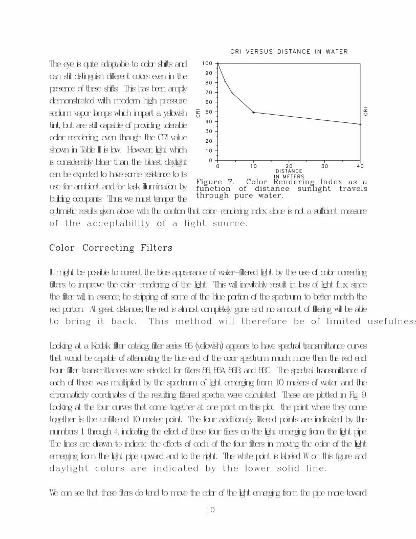
Figure 7. Color Rendering Index as afunction of distance sunlight travelsthrough pure water.
The eye is quite adaptable to color shifts andcan still distinguish different colors even in thepresence of these shifts. This has been amplydemonstrated with modern high pressuresodium vapor lamps which impart a yellowishtint, but are still capable of providing tolerablecolor rendering, even though the CRI valueshown in Table III is low. However, light whichis considerably bluer than the bluest daylightcan be expected to have some resistance to itsuse for ambient and/or task illumination bybuilding occupants. Thus, we must temper theoptimistic results given above with the caution that color-rendering index alone is not a sufficient measureof the acceptability of a light source.
Color-Correcting Filters
It might be possible to correct the blue appearance of water-filtered light by the use of color correctingfilters, to improve the color-rendering of the light. This will inevitably result in loss of light flux, sincethe filter will, in essence, be stripping off some of the blue portion of the spectrum to better match thered portion. At great distances, the red is almost completely gone and no amount of filtering will be ableto bring it back. This method will therefore be of limited usefulness
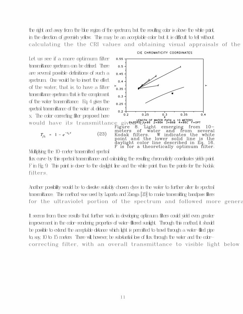
Looking at a Kodak filter catalog, filter series 86 (yellowish) appears to have spectral transmittance curvesthat would be capable of attenuating the blue end of the color spectrum much more than the red end.Four filter transmittances were selected, for filters 86, 86A, 86B, and 86C. The spectral transmittance ofeach of these was multiplied by the spectrum of light emerging from 10 meters of water and thechromaticity coordinates of the resulting filtered spectra were calculated. These are plotted in Fig. 9.Looking at the four curves that come together at one point on this plot, the point where they cometogether is the unfiltered 10 meter point. The four additionally filtered points are indicated by thenumbers 1 through 4, indicating the effect of these four filters on the light emerging from the light pipe.The lines are drawn to indicate the effects of each of the four filters in moving the color of the lightemerging from the light pipe upward and to the right. The white point is labeled W on this figure anddaylight colors are indicated by the lower solid line.
We can see that these filters do tend to move the color of the light emerging from the pipe more toward
11
Figure 8. Light emerging from 10-meters of water and from severalKodak filters. W indicates the whitepoint and the lower solid line is thedaylight color line described in Eq. 16.F is for a theoretically optimum filter.
(23)
the right and away from the blue region of the spectrum, but the resulting color is above the white point,in the direction of greenish yellow. This may be an acceptable color but it is difficult to tell withoutcalculating the the CRI values and obtaining visual appraisals of the
Let us see if a more optimum filtertransmittance spectrum can be defined. Thereare several possible definitions of such aspectrum. One would be to invert the effectof the water, that is, to have a filtertransmittance spectrum that is the complementof the water transmittance. Eq. 4 gives thespectral transmittance of the water at distancex. The color correcting filter proposed herewould have its transmittance given by
Multiplying the 10-meter transmitted spectralflux curve by this spectral transmittance and calculating the resulting chromaticity coordinates yields pointF in Fig. 9. This point is closer to the daylight line and the white point than the points for the Kodakfilters.
Another possibility would be to dissolve suitably chosen dyes in the water to further alter its spectraltransmittance. This method was used by Laporta and Zaraga [20] to make transmitting bandpass filtersfor the ultraviolet portion of the spectrum and followed more genera
It seems from these results that further work in developing optimum filters could yield even greaterimprovement in the color-rendering properties of water-filtered sunlight. Through this method, it shouldbe possible to extend the acceptable distance which light is permitted to travel through a water-filled pipeto, say, 10 to 15 meters. There will, however, be substantial loss of flux through the water and the color-correcting filter, with an overall transmittance to visible light below
12
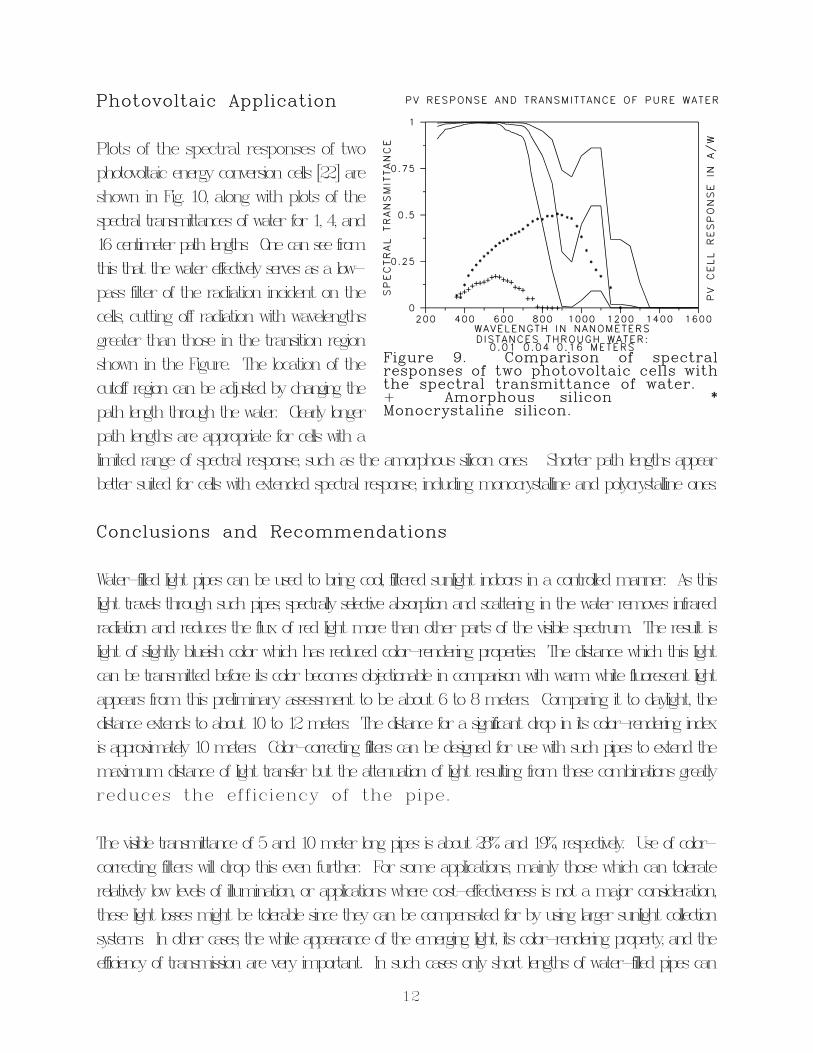
Figure 9. Comparison of spectralresponses of two photovoltaic cells withthe spectral transmittance of water.+ Amorphous silicon *Monocrystaline silicon.
Photovoltaic Application
Plots of the spectral responses of twophotovoltaic energy conversion cells [22] areshown in Fig. 10, along with plots of thespectral transmittances of water for 1, 4, and16 centimeter path lengths. One can see fromthis that the water effectively serves as a low-pass filter of the radiation incident on thecells, cutting off radiation with wavelengthsgreater than those in the transition regionshown in the Figure. The location of thecutoff region can be adjusted by changing thepath length through the water. Clearly longerpath lengths are appropriate for cells with alimited range of spectral response, such as the amorphous silicon ones. Shorter path lengths appearbetter suited for cells with extended spectral response, including monocrystalline and polycrystalline ones.
Conclusions and Recommendations
Water-filled light pipes can be used to bring cool, filtered sunlight indoors in a controlled manner. As thislight travels through such pipes, spectrally selective absorption and scattering in the water removes infraredradiation and reduces the flux of red light more than other parts of the visible spectrum. The result islight of slightly blueish color which has reduced color-rendering properties. The distance which this lightcan be transmitted before its color becomes objectionable in comparison with warm white fluorescent lightappears from this preliminary assessment to be about 6 to 8 meters. Comparing it to daylight, thedistance extends to about 10 to 12 meters. The distance for a significant drop in its color-rendering indexis approximately 10 meters. Color-correcting filters can be designed for use with such pipes to extend themaximum distance of light transfer but the attenuation of light resulting from these combinations greatlyreduces the efficiency of the pipe.
The visible transmittance of 5 and 10 meter long pipes is about 28% and 19%, respectively. Use of color-correcting filters will drop this even further. For some applications, mainly those which can toleraterelatively low levels of illumination, or applications where cost-effectiveness is not a major consideration,these light losses might be tolerable since they can be compensated for by using larger sunlight collectionsystems. In other cases, the white appearance of the emerging light, its color-rendering property, and theefficiency of transmission are very important. In such cases only short lengths of water-filled pipes can
13
[1] Selkowitz, S. E. and R. Johnson, "The Daylighting Solution," Solar Age, Vol. 5, No. 8, August 1980,pp 14-20.
[2] Griffith, J. W., "Daylight and Energy Conscious Design," ASHRAE Transactions, DE-79-5, No. 4, 1979pp. 664-668. Treado, S., G. Gillette, and T. Kusuda, "Evaluation of the Daylighting and EnergyPerformance of Windows, Skylights, and Clerestories", National Institute for Standards and Technology(formerly NBS), Pub. NBSIR 83-2726, June 1983.
[3] Benton, C. C., "Daylighting Can Improve the Quality of Light and Save Energy," ArchitecturalLighting, Vol. 1, Nov. 1986, pp. 46-48. Oddo, S., "Surprising Discoveries About Why You Need More NaturalLight," House and Garden, Vol. 148, Feb. 1976, pp. 78-79. Gillette, G., "The Case for Daylighting," TheConstruction Specifier, March 1984, pp. 58-63.
[4] McCluney, R., "Bringing in the Sun," Glass Magazine, August 1986,
[5] Selkowitz, S. E., "What Makes Daylighting Effective?" Energy Management, June/July, 1982, pp. 32-34,71. McCluney, R. "Daylighting in America -- Some Practical Suggestions for Proper Usage," Lighting
be used.
It seems that the best solution in such cases would be a hybrid combination of air-filled and water-filledlight pipes. The water-filled section would strip off the infrared portion of the spectrum, reducing thethermal energy content of the emerging beam, and the air-filled portion would distribute the light to theareas needing illumination. The higher refractive index of water could serve an optical purpose in thedesign of the concentrating collector used to focus sunlight on the pipe. The water could fill the collector(if the structural loading resulting from the weight of the water can be handled acceptably) therebyincreasing the concentration ratio. The water-filled portion could be placed at the focus of theconcentrator, and shaped to improve flux throughput. Other hybrid possibilities can be explored for specialapplication areas.
The possibilities for use of water to filter the radiation impinging upon solar photovoltaic energy conversionarrays are intriguing and should be explored further. Not only can the water remove unused infraredradiation from the illuminating beam but also it can be employed as a cooling medium, lowering theoperating temperatures of the array and hence increasing conversion
Acknowledgement
Portions of this work were supported by the Assistant Secretary for Conservation and Renewable Energy,Office of Buildings and Community Systems, Building Systems Division of the U.S. Department of Energythrough grant DE-FG01-84CE22122.
References
14
Design & Application, July 1985, pp. 36-38. Shanus, M. D., et. al., "Going Beyond the Perimeter withDaylight," Lighting Design & Application, March 1984, p. 30-40.
[6] Fraas, L. M., W. R. Pyle, and P. R. Ryason, "Concentrated and Piped Sunlight for IndoorIllumination," Applied Optics, Vol. 22, No. 4, 15 Feb., 1983, p. 578-582. Duguay, M. A., "Solar Electricity:The Hybrid System Approach," American Scientist, Vol. 65, July/August, 1977, pp. 422-427. Duguay, M.A. and R. M. Adgar, "Lighting with Sunlight Using Sun Tracking Concentrators," Applied Optics, Vol. 16, No.5, May 1977, pp. 1444-1446. Littlefair, P., "Beam Lighting: A Pipe Dream?," Electrical Design, May 1986,pp. 31-33.
[7] Klank, B. and Gerod, D., "Daylighting with 'Fibre-Optics' Like Water Tubes," Proc., 9th Passive SolarConference, Columbus, Ohio, American Solar Energy Society, 2400 Central Ave., Suite B-1, Boulder, CO80301, Sept. 1984.
[8] Illuminating Engineering Society of North America, IES Lighting Handbook 1981 Reference Volume,1981, Fig. 3-7, p. 3-5.
[9] Jerlov, N. G., Marine Optics, Elsevier, New York, 1976.
[10] Morel, A., "Chapter 1. Optical Properties of Pure Water and Pure Sea Water," Optical Aspects ofOceanography, N. G. Jerlov and E. S. Nielsen, eds., Academic Press, Ne
[11] Wyszecki, G., and W. S. Stiles, Color Science: Concepts and Methods, Quantitative Data andFormulas, Wiley, 1967.
[12] Kelley, K. L., "Lines of Constant Correlated Color Temperature Based on MacAdam's (u,v) UniformChromaticity Transformation of the CIE Diagram," J. Opt. Soc. Am., 53,999 (1963). Driscoll, W. G., andVaughan, W., Handbook of Optics McGraw-Hill, New York, 1978. Robertson, A. R., "Computation ofCorrelated Color Temperature and Distribution Temperature," J. Opt. S
[13] Illuminating Engineering Society of North America, IES Lighting Handbook Reference Volume, 1984,p. 5-14.
[14] Judd, D. B., D. L. MacAdam, and G. Wyszecki, J. Opt. Soc. Am. 54,
[15] Inagaki, T., Oki, M., and Nakamura, H., "Study on Colour Temperature of Light From Sky and itsDistribution in Japan," Proceedings of the 6th Session of the Association Internationale de la Colour,Buenos Aires, Argentina, 1989, Vol. II - Papers.
[16] CIE, Method of Measuring and Specifying Colour Rendering Properties of Light Sources, CIEPublication no. 13.2 (TC 3.2), 1974.
[17] Kelley, K. L., J. Opt. Soc. Am. 53, 999 (1963).
[18] Wyszecki, G., "Section 9. Colorimetry", Handbook of Optics, W. G. Driscoll and W. Vaughan, eds.,McGraw-Hill, New York, 19xx.
[19] Nickerson, D. and C. W. Jerome, "Color Rendering of Light Sources: CIE Method of Specificationand Its Application," Illuminating Engineering, Vol. 60, No. 4, April 196
[20] Laporta, P. and Zaraga, F., "Computer Design of Liquid Filters Made of Aqueous Solutions ofTransition Metal Ions," Applied Optics 20,2946 (1981).
[21] Ingersoll, K. A., Applied Optics, 10, 2781 (1971); 11, 2473 (1972);
15
[22] Emery, K. A., et. al., "SERI Results from the PEP 1987 Summit Round Robin and a Comparisonof Photovoltaic Calibration Methods," Solar Energy Research Institute, 1617 Cole Blvd., Golden CO 80401,Report: SERI/TR-213-3472, March 1989, p.28.
Related Documents