Broadcast Equipment

Welcome message from author
This document is posted to help you gain knowledge. Please leave a comment to let me know what you think about it! Share it to your friends and learn new things together.
Transcript

Broadcast Equipment
Collins Broadcast, Equipment
TABLE OF CONTENTS
AM Transmitters 2 Tape Equipment 91 Phasing 12 Microphones 102 FM Transmitters 17 Studio Accessories 106 Antennas 32 Measuring, Monitoring 117 Towers 35 Remote Control 124 Transmission Lines & Accessories .... 38 STL Microwave 125 Audio Facilities 70 Tables, Charts, Graphs 128 Disc Equipment 84 Indices 148
Collins Sales Policy is found at the back of this catalog.
Equipment descriptions in this catalog were condensed so that the complete line of broad- cast units supplied by Collins Radio Company could be shown. For more information on any of these units, you are invited to contact your Collins Broadcast Sales Engineer or Collins Radio Company, Broadcast Communication Division, Dallas, Texas.
Customers in countries other than the United States are invited to contact the nearest Inter- national Sales Office or Collins International, World Headquarters, Dallas, Texas.

COLLINS
The reputation of Collins Radio Company has been built on more than a quarter of a century of research.
development and manufacture of distinctive electronic equipment. To assure broadcasters of the very
finest equipment, Collins engineers and technicians follow without exception this company -wide philosophy :
Design and build equipment based on technical ingenuity, unique function and quality of craftsmanship,
rather than solely on the grounds of price and sales effort.
Whatever the field - broadcast, amateur radio, aviation electronics, military or industrial communica-
tion, or space communication-Collins adheres strictly to its basic code that there is no substitute for quality.
Collins research and development, its staff of highly competent field technicians and the Company's never
ending stress on quality control assure each Collins broadcast equipment owner that he has the most
advanced, thoroughly tested equipment available, and that it will retain its value through the years.
In this catalog is the latest equipment of the complete broadcast line that has earned Collins its unparalleled
reputation in the field. Collins famous quality and reliability are integral parts of all these units.
AM Transmitters and Phasing
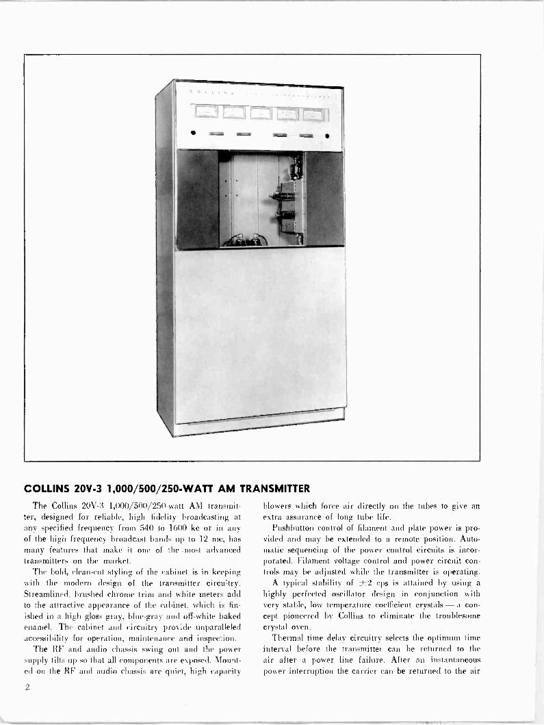
COLLINS 20V-3 1,000/500/250 -WATT AM TRANSMITTER
The Collins 20V-3 1,000/500/250 -watt AM transmit- ter, designed for reliable, high fidelity broadcasting at any specified frequency from 540 to 1600 kc or in any of the high frequency broadcast bands up to 12 mc, has many features that make it one of the .most advanced transmitters on the market.
The bold, clean-cut styling of the cabinet is in keeping with the modern design of the transmitter circuitry. Streamlined, brushed chrome trim and white meters add to the attractive appearance of the cabinet, which is fin-
ished in a high gloss gray, blue -gray and off-white baked enamel. The cabinet and circuitry provide unparalleled accessibility for operation, maintenance and inspection.
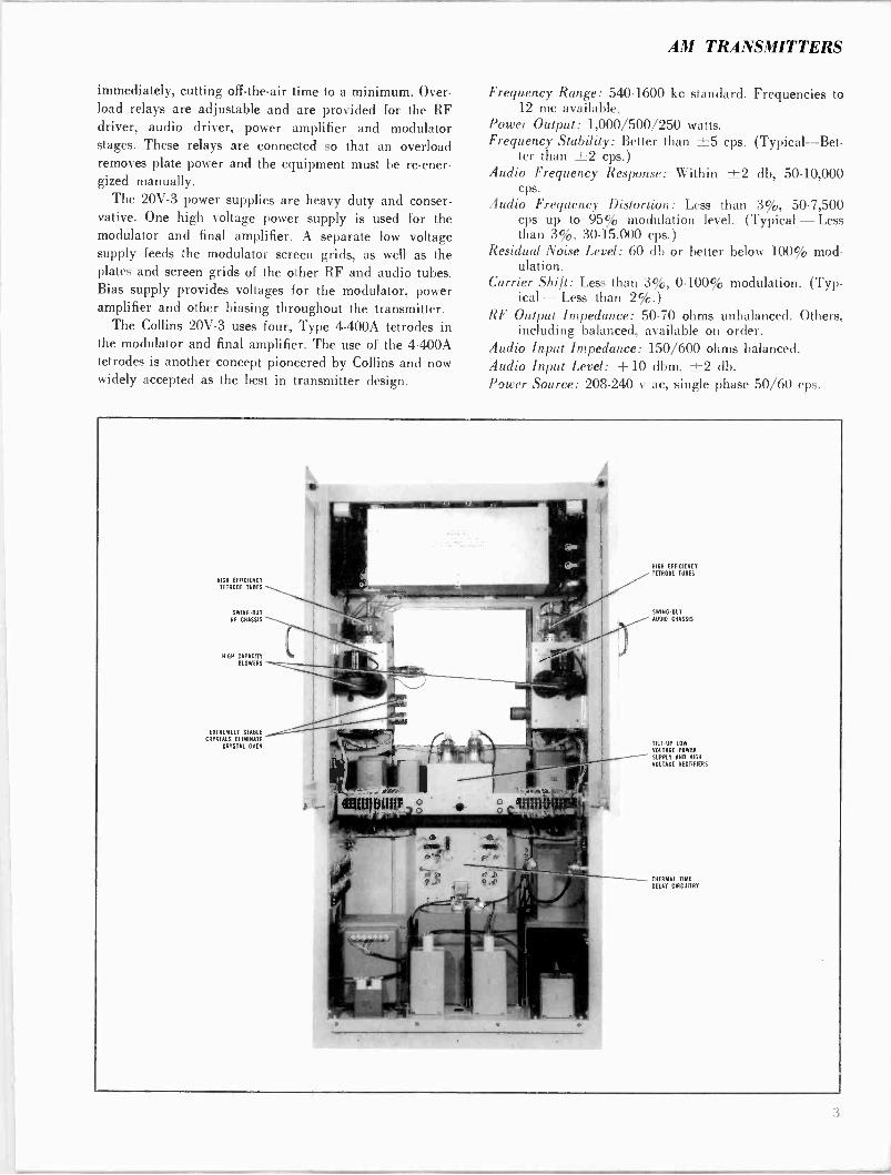
The RF and audio chassis swing out and the power supply tilts up so that all components are exposed. Mount- ed on the RF and audio chassis are quiet, high capacity
blowers which force air directly on the tubes to give an extra assurance of long tube life.
Pushbutton control of filament and plate power is pro- vided and may be extended to a remote position. Auto- matic sequencing of the power control circuits is incor- porated. Filament voltage control and power circuit con- trols may be adjusted while the transmitter is operating.
A typical stability of ±2 cps is attained by using a highly perfected oscillator design in conjunction with very stable, low temperature coefficient crystals -a con- cept pioneered by Collins to eliminate the troublesome crystal oven.
Thermal time delay circuitry selects the optimum time interval before the transmitter can be returned to the air after a power line failure. After an instantaneous power interruption the carrier can be returned to the air
2
AM TRANSMITTERS
immediately, cutting off -the -air time to a minimum. Over- load relays are adjustable and are provided for the RF driver, audio driver, power amplifier and modulator stages. These relays are connected so that an overload removes plate power and the equipment must be re -ener- gized manually.
The 20V-3 power supplies are heavy duty and conser- vative. One high voltage power supply is used for the modulator and final amplifier. A separate low voltage supply feeds the modulator screen grids, as well as the plates and screen grids of the other RF and audio tubes. Bias supply provides voltages for the modulator, power amplifier and other biasing throughout the transmitter.
The Collins 20V-3 uses four, Type 4-400A tetrodes in the modulator and final amplifier. The use of the 4-400A tetrodes is another concept pioneered by Collins and now widely accepted as the best in transmitter design.
Frequency Range: 540-1600 kc standard. Frequencies to 12 me available.
Power Output: 1,000/500/250 watts. Frequency Stability: Better than ±5 cps. (Typical-Bet-
ter than ±2 cps.) Audio Frequency Response: Within ±2 db, 50-10,000
cps. Audio Frequency Distortion: Less than 3%, 50-7,500
cps up to 95% modulation level. (Typical - Less than 3%, 30-15,000 cps.)
Residual Noise Level: 60 db or better below 100% mod- ulation.
Carrier Shift: Less than 3%, 0-100% modulation. (Typ- ical - Less than 2%.)
RF Output Impedance: 50-70 ohms unbalanced. Others, including balanced, available on order.
Audio Input Impedance: 150/600 ohms balanced. Audio Input Level: + 10 dbm, ±2 db. Power Source: 208-240 v ac, single phase 50/60 cps.
HIGH EFFICIENCY
TETRODE TUBES
SWING OUT
RF CHASSIS
HIGH CAPACITY BLOWERS
EXTREMELY STABLE
CRYSTALS ELIMINATE
CRYSTAL OYEN
HIGH EFFICIENCY
TETROOE TUBES
SWING -OUT AUDIO CHASSIS
TILT -UP LOW
VOLTAGE POWER
SUPPLY AND MGR
VOLTAGE RECTIFIERS
- THERMAL TIME
DELAY CIRCUITRY

XTAL OSC
6AU6
BUFFER AMPL 6SJ7
DRIVER AMPL 807
0 -- AUDIO INPUT
O - AUDIO DRIVER
(2) 6SJ7
POWER AMPL
(2) 4-400A
MOD
(2) 4-400A
BIAS SUPPLY
5U4G
LOW VOLTAGE SUPPLY
(2) 866A
TANK AND
OUTPUT CIRCUIT
HIGH VOLTAGE SUPPLY
(2) 575A
RF OUTPUT
BLOCK DIAGRAM 20V-3
Power Demand (at 1,000 watts output) :
Filaments 660 watts 85% pf 0% modulation 2,950 watts 80% pf
30% modulation 3,250 watts 83% pf 100% modulation 4,150 watts 83% pf
Tube Complement:
4 4-400A
1 807
3 6SJ7
1 6AU6 2 575A 2 866A 1 5114G
2 Final Amplifier 2 - Modulator Driver Amplifier 1 Buffer Amplifier 2 - Audio Amplifier Crystal Oscillator High Voltage Rectifier Low Voltage Rectifier Bias Rectifier
Ambient Temperature Range: + 15°C to + 45°C.
Size: 38" W, 76" H. 27" D (96.52 cm W, 103.04 cm H. 68.58 cm D) .
Weight: Approx. 1,295 lbs (587.41 kg). Part No. 522 2480
Includes one set of tubes, one crystal and one instruction book.
No Part Number Complete set of spare tubes.
No Part Number FCC set of spare tubes.
No Part Number Factory short wave conversion, 1.6 mc -I2 mc.
No Part Number Spare crystal for 20V and 550A transmitters.
4
AM TRANSMITTERS
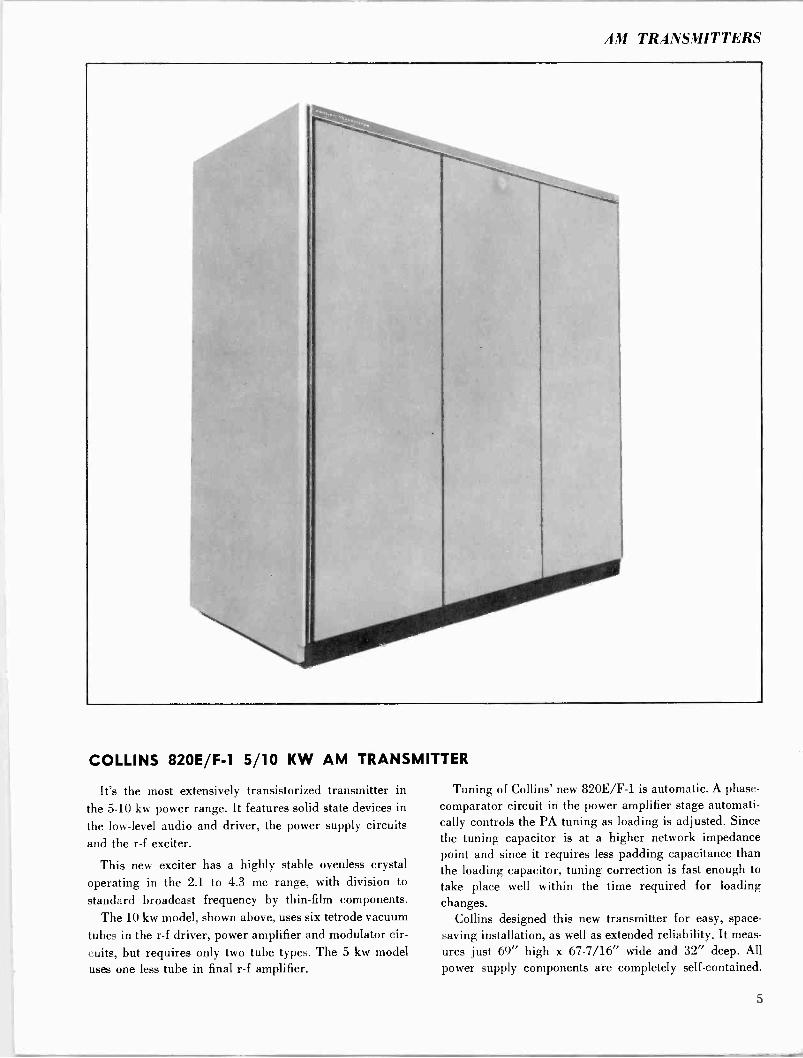
COLLINS 820E/F-1 5/10 KW AM TRANSMITTER
It's the most extensively transistorized transmitter in
the 5-10 kw power range. It features solid state devices in
the low-level audio and driver, the power supply circuits
and the r -f exciter.
This new exciter has a highly stable ovenless crystal
operating in the 2.1 to 4.3 me range, with division to
standard broadcast frequency by thin-film components.
The 10 kw model, shown above, uses six tetrode vacuum tubes in the r -f driver, power amplifier and modulator cir-
cuits, but requires only two tube types. The 5 kw model uses one less tube in final r -f amplifier.
Tuning of Collins' new 820E/F-1 is automatic. A phase - comparator circuit in the power amplifier stage automati- cally controls the PA tuning as loading is adjusted. Since the tuning capacitor is at a higher network impedance point and since it requires less padding capacitance than the loading capacitor, tuning correction is fast enough to take place well within the time required for loading changes.
Collins designed this new transmitter for easy, space - saving installation, as well as extended reliability. It meas-
ures just 69" high x 67-7/16" wide and 32" deep. All power supply components are completely self-contained.
5
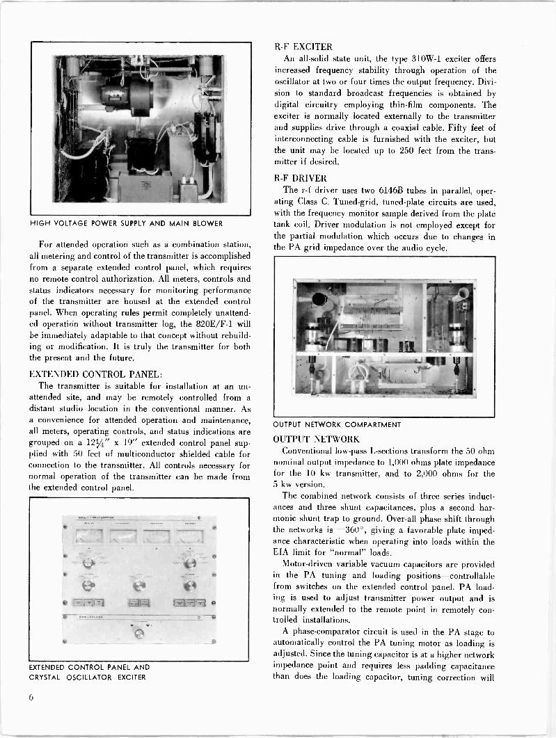
HIGH VOLTAGE POWER SUPPLY AND MAIN BLOWER
For attended operation such as a combination station, all metering and control of the transmitter is accomplished from a separate extended control panel, which requires no remote control authorization. All meters, controls and status indicators necessary for monitoring performance of the transmitter are housed at the extended control panel. When operating rules permit completely unattend- ed operation without transmitter log, the 820E/F-1 will be immediately adaptable to that concept without rebuild- ing or modification. It is truly the transmitter for both the present and the future.
EXTENDED CONTROL PANEL: The transmitter is suitable for installation at an un-
attended site, and may be remotely controlled from a distant studio location in the conventional manner. As a convenience for attended operation and maintenance, all meters, operating controls, and status indications are grouped on a 1214" x 19" extended control panel sup- plied with 50 feet of multiconductor shielded cable for connection to the transmitter. All controls necessary for normal operation of the transmitter can be made from the extended control panel.
EXTENDED CONTROL PANEL AND
CRYSTAL OSCILLATOR EXCITER
R -F EXCITER An all -solid state unit, the type 310W-1 exciter offers
increased frequency stability through operation of the oscillator at two or four times the output frequency. Divi- sion to standard broadcast frequencies is obtained by digital circuitry employing thin-film components. The exciter is normally located externally to the transmitter and supplies drive through a coaxial cable. Fifty feet of interconnecting cable is furnished with the exciter, but the unit may be located up to 250 feet from the trans- mitter if desired.
R -F DRIVER The r -f driver uses two 6146B tubes in parallel, oper-
ating Class C. Tuned -grid, tuned -plate circuits are used, with the frequency monitor sample derived from the plate tank coil. Driver modulation is not employed except for the partial modulation which occurs due to changes in the PA grid impedance over the audio cycle.
OUTPUT NETWORK COMPARTMENT
OUTPUT NETWORK Conventional low-pass L -sections transform the 50 ohm
nominal output impedance to 1,000 ohms plate impedance for the 10 kw transmitter, and to 2,000 ohms for the 5 kw version.
The combined network consists of three series induct- ances and three shunt capacitances, plus a second har- monic shunt trap to ground. Over-all phase shift through the networks is -360°, giving a favorable plate imped- ance characteristic when operating into loads within the EIA limit for "normal" loads.
Motor -driven variable vacuum capacitors are provided in the PA tuning and loading positions-controllable from switches on the extended control panel. PA load- ing is used to adjust transmitter power output and is normally extended to the remote point in remotely con- trolled installations.
A phase -comparator circuit is used in the PA stage to automatically control the PA tuning motor as loading is adjusted. Since the tuning capacitor is at a higher network impedance point and requires less padding capacitance than does the loading capacitor, tuning correction will
O
AM TRANSMITTERS
occur at a more rapid rate, and within the time required for loading changes. The tuning function is not normally extended to the remote control point, and to assure fail- safe operation, the automatic tuning adjustment is dis- abled until loading changes take place. A Manual/Auto- matic Tuning switch is provided on the extended control panel to disable the automatic mode during maintenance checks.
SPECIFICATIONS
Frequency Range: 540.1600 kc Power Source: 208/240 volts, ±5%, 50/60 cycles, three
phase. Power Output: 820E-1:5.5 kw max with built-in reduction
to 1 kw. 820E-1:10.6 kw max with built-in reduction to 5 kw.
Frequency Stability: Trimmer capacitors provided on the r -f exciter for adjusting crystals to exact center fre- quency. Stability as follows:
±5 cps, 0°C to +35°C (32°F to 95°F) ±10 cps, -10°C to +45°C (14°F to 113°F)
Output Impedance: Designed for feeding standard 50 ohm coaxial transmission lines. Matching to other impedance options can be supplied on special order.
Harmonic and Spurious Radiation: Complies with or ex- ceeds FCC regulations regarding harmonic and spuri- ous radiaton.
Modulation Characteristics: Equipment incorporates high level modulation with most desirable response charac teristics for broadcast use.
Audio Input Impedance: 150/600 ohm, balanced. Audio Input Level: +10 dbm ±2 db. Audio Frequency Response: Typically ±1.5 db from 50
cps to 10,000 cps. Audio Frequency Distortion: Less than 3% from 50 to
7,500 cps, for 95% modulation. Noise: 60 db below 100% modulation. Carrier Shift: Less than 3% from zero to 100% modula-
tion. Ambient Temperature Range: -25°C to +45°C (-13°F
to 113°F). Altitude: Up to 7,000 feet; higher altitudes on special
order. Size: 69 inches high by 67-7/16 inches wide by 32 inches
deep (175 cm. X 171 cm. X 81 cm.) .
Total Weight Including Transformers: 820E-1, 2,000 lbs. (910 Kg.) ; 820F-1, 2,450 lbs. (1115 Kg.) .
Part No. 522 3291 000 (Type 820E-1) Includes one set of tubes, one crystal and one instruction book.
No Port Number Complete set of spare tubes for 820E-1.
No Part Number FCC set of spare tubes for 820E -I.
Part No. 522 3292 000 (Type 820F-1) Includes one set of tubes, one crystal and one instruction book.
No Part Number Complete set of spare tubes for 820F-1.
No Part Number FCC set of spare tubes for 820F.
No Part Number Spare crystal for 820E / F-1.
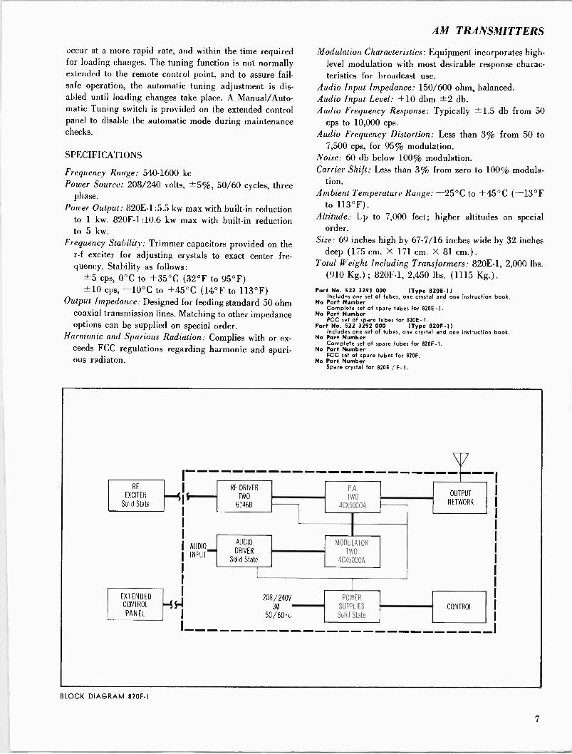
RF RF DRIVER P.A.
EXCITER TWO TWO -. Solid State 61468 4CX5000A
AUDIO
NPUT
AUDIO
DRIVER
Solid State
MODULATOR
TWO
4CX5000A
208/240V EXTENDEDFs CONTROL
POWER
SUPPLIES 30 PANEL 50/601. Solid State
U OUTPUT
NETWORK
CONTROL
BLOCK DIAGRAM 820F -I
7
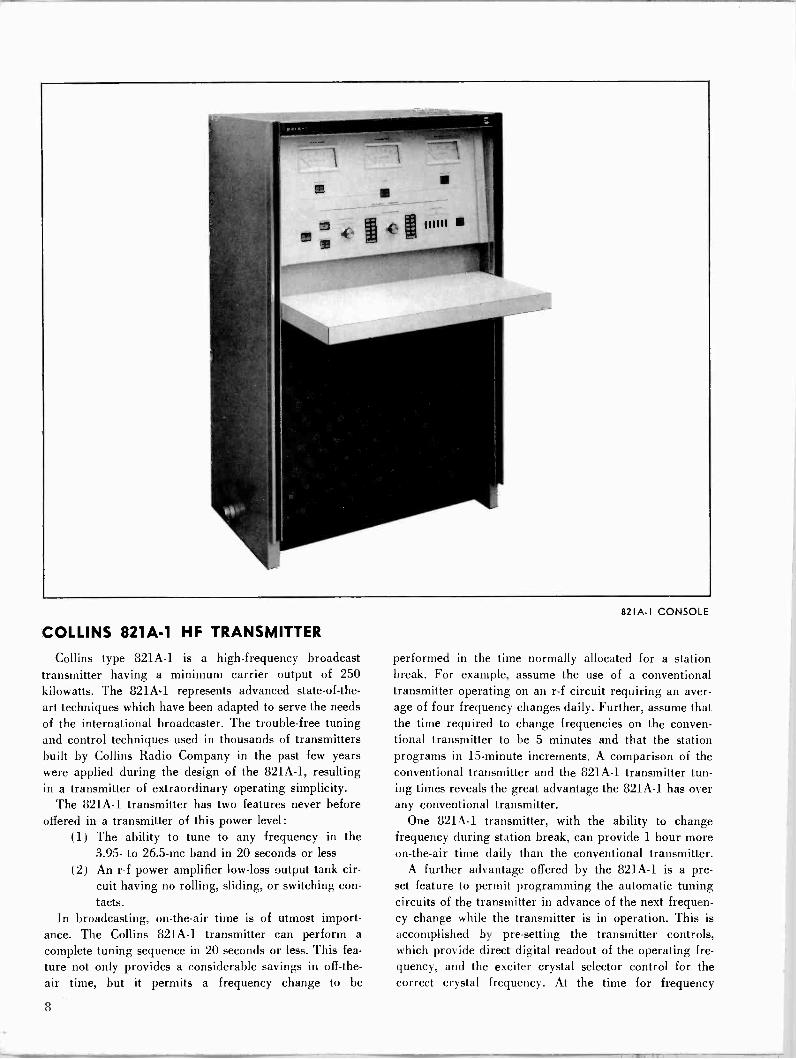
COLLINS 821A-1 HF TRANSMITTER
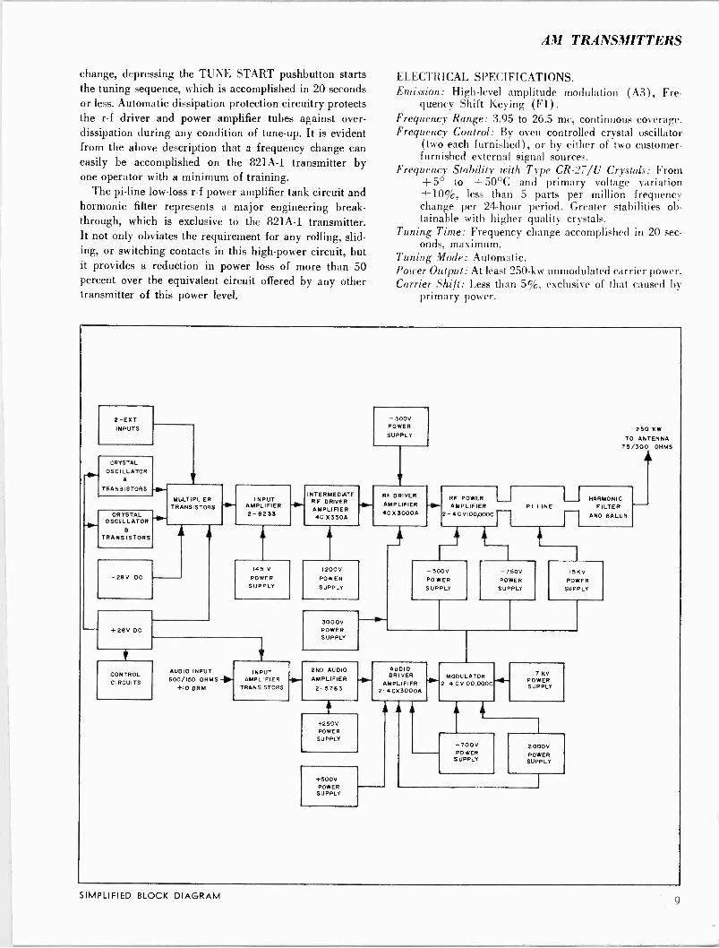
Collins type 821A-1 is a high -frequency broadcast transmitter having a minimum carrier output of 250 kilowatts. The 821A,-1 represents advanced state-of-the- art techniques which have been adapted to serve the needs of the international broadcaster. The trouble -free tuning and control techniques used in thousands of transmitters built by Collins Radio Company in the past few years were applied during the design of the 821A-1, resulting in a transmitter of extraordinary operating simplicity.
The 821A-1 transmitter has two features never before offered in a transmitter of this power level:
(1) The ability to tune to any frequency in the 3.95- to 26.5 -mc band in 20 seconds or less
(2) An r -f power amplifier low -loss output tank cir- cuit having no rolling, sliding, or switching con- tacts.
In broadcasting, on -the -air time is of utmost import- ance. The Collins 821A-1 transmitter can perform a complete tuning sequence in 20 seconds or less. This fea-
ture not only provides a considerable savings in off -the - air time, but it permits a frequency change to be
821A -I CONSOLE
performed in the time normally allocated for a station break. For example, assume the use of a conventional transmitter operating on an r -f circuit requiring an aver- age of four frequency changes daily. Further, assume that the time required to change frequencies on the conven- tional transmitter to be 5 minutes and that the station programs in 15 -minute increments. A comparison of the conventional transmitter and the 821A-1 transmitter tun- ing times reveals the great advantage the 821A-1 has over any conventional transmitter.
One 821A-1 transmitter, with the ability to change frequency during station break, can provide 1 hour more on -the -air time daily than the conventional transmitter.
A further advantage offered by the 821A-1 is a pre- set feature to permit programming the automatic tuning circuits of the transmitter in advance of the next frequen- cy change while the transmitter is in operation. This is
accomplished by pre-setting the transmitter controls, which provide direct digital readout of the operating fre- quency, and the exciter crystal selector control for the correct crystal frequency. At the time for frequency
8
AM TRANSMITTERS
change, depressing the TUNE START pushbutton starts the tuning sequence, which is accomplished in 20 seconds or less. Automatic dissipation protection circuitry protects the r -f driver and power amplifier tubes against over - dissipation during any condition of tune-up. It is evident from the above description that a frequency change can easily be accomplished on the 821A-1 transmitter by one operator with a minimum of training.
The pi -line low -loss r -f power amplifier tank circuit and hormonic filter represents a major engineering break- through, which is exclusive to the 821A-1 transmitter. It not only obviates the requirement for any rolling, slid- ing, or switching contacts in this high -power circuit, but it provides a reduction in power loss of more than 50 percent over the equivalent circuit offered by any other transmitter of this power level.
ELECTRICAL SPECIFICATIONS. Emission: High-level amplitude modulation (A3), Fre-
quency Shift Keying (F1). Frequency Range: 3.95 to 26.5 mc, continuous coverage. Frequency Control: By oven controlled crystal oscillator
(two each furnished), or by either of two customer - furnished external signal sources.
Frequency Stability with Type CR -27/U Crystals: From + 5° to + 50°C and primary voltage variation ±10%, less than 5 parts per million frequency change per 24 -hour period. Greater stabilities ob- tainable with higher quality crystals.
Tuning Time: Frequency change accomplished in 20 sec- onds, maximum.
Tuning Mode: Automatic. Power Output: At least 250 -kw unmodulated carrier power. Carrier Shift: Less than 5%, exclusive of that caused by
primary power.
2-EXT INPUTS
CRYSTAL OSCILLATOR
A
TRANSISTORS
CRYSTAL OSCILLATOR
B TRANSISTORS
MULTIPLIER TRANSISTORS
INPUT AMPLIFIER 2-8233
INTERMEDIATE R F DRIVER AMPLIFIER 4C X350A
- 300V POWER
SUPPLY
RF DRIVER AMPLIFIER 4C X 3000A
RF POWER AMPLIFIER
2-4CVIOOpOOC PI LINE
250 KW
TO ANTENNA 75/300 OHMS
HARMONIC FILTER
AND BALUN
J
145 V 1200V - 500V - 750V ISKV -28V DC POWER POWER POWER POWER POWER
SUPPLY SUPPLY SUPPLY SUPPLY SUPPLY
+28V DC
T
CONTROL CIRCUITS
AUDIO INPUT 600/150 OHMS
+10 DBM
INPUT AMPLIFIER
TRANSISTORS
3000V POWER SUPPLY
2ND AUDIO
AMPLIFIER
2-5763
f +250V POWER
SUPPLY
h
+500V POWER SUPPLY
AUDIO DRIVER
AMPLIFIER 2-4CX3000A
H
f' MODULATORii 1..... 2-4 C VIOO,000C
17 KV POWER SUPPLY
4
- 700V POWER
SUPPLY
2000V POWER SUPPLY
SIMPLIFIED BLOCK DIAGRAM
Output Impedance: 300 ohms, balanced; 75 ohms, unbal- anced.
VSWR: 1.5:1, maximum. Type of Modulation: High-level AM, FSK. Modulation Capability: Capable of 100% sine wave or
clipped sine wave. Less than 5% tilt or overshoot for trapezoidal waveform from 100 to 3000 cps.
Modulation Duty Factor: Continuous at 100% sine wave; 5 minutes at 100%, clipped sine wave.
Audio Input for 100% Modulation: + 10 dbm, ±2 db. Audio Input Impedance: 600/150 ohms, balanced or un-
balanced. Audio Response: Within 1 db from that at 1000 cps be-
tween 100 and 7500 cps and within 2 db between 50 to 10,000 cps, at all modulation levels up to 95%.
Audio Distortion: Not more than 4% distortion when modulated 100% over the frequency range of 100 to 5000 cps; and not more than 5% from 50 to 100 cps and from 5000 to 7500 cps.
Noise Level: Carrier hum and extraneous noise is at least 50 db (unweighted) below 100% modulation.
Harmonic and Spurious: All harmonics and harmonically related spurious emissions are at least 80 db below carrier level. Incidental phase modulation products that occur close to the carrier and are a result of (1) random crystal variations, (2) power supply ripple, (3) power supply regulation during modulation, (4) mechanical vibration of the crystal, and which ap- pear in the output of the transmitter are at least 43 db below 1 radian.
Power Input: At Rated Carrier Output: 455 kw at 85% pf At 100% Sine Wave: 682 kw at 85% pf
Power Source: 4160 volts, ±3%; 60 cps, ±5%, 3 -phase, 3 -wire (50 cps optional).
Altitude: 0 to 6000 feet. Temperature: + 5° to +50°C at sea level; +5° to
+ 38°C at 6000 feet. Humidity: 0 to 95% relative humidity. Storage: -35° to + 60°C. Power Source: 4160 volts ±3% (steady state) ±33%
(instantaneous) ; 60 cps ±5% (steady state) ; ±3% Iinstantaneous) (50 cps optional)
No Part Number
10

AM TRANSMITTERS
JOHNSON FEED -THROUGH BOWL INSULATORS
Designed to carry RF transmission line through a wall. Assembly includes glass bowls, cork gasket, steel mount- ing with six 3/16" mounting holes. Bowl is 6 15/16" max. diameter and 43/8" high. Mounting flange: 73/4" diameter. Fittings include spun aluminum corona shield, 1/2"-13 threaded stud except 135-15-4 which has 5/18"-18 threaded stud (hollow), washers, and nuts. Part No. 097 1501 000 (Type 135-15-1)
One bowl and fittings, 101/4" stud. Part No. 097 6673 000 (Type 135-15-3)
Two bowls and fittings, 16" stud for walls up to 4" thick. Part No. 099 1170 000 (Type 135-15-4)
Two bowls and fittings, 24" hollow stud I.D. 7/16" for walls up to 12" thick.
Part No. 097 5646 000 (Type 135-15-7) Two bowls and fittings, 24" stud for walls up to 12" thick.
COLLINS 172G DUMMY ANTENNA This air-cooled unit provides a load to dissipate trans-
mitter output for off -the -air testing. Consisting of 8
ferrule type, non -inductive resistors, with insulated end brackets and clips, it may be mounted on the transmitter or adjacent wall. The 172G-1 has an impedance of 52 ohms; the 172G-2, 73 ohms.
Power Rating: 1 kw. Size: Approx. 6" W, 9" H, 121/2" D (15.24 cm W, 22.86
cm H, 31.75 cm D). Weight: 5 lbs. (2.27 kg) .
Part No. 522 1410 014 (Type 172G-1) Part No. 522 1411 014 (Type 172G-2)
STATES WG -52 DUMMY ANTENNA An air-cooled dummy load to dissipate output of the
Collins 21E AM Transmitter. The WG -52 has an im- pedance of 52 ohms and a peak of 7.5 kw. Part No. 097 8138 00
COLLINS TOWER LIGHTING FILTER CHOKES
These solenoid wound 2- and 3 -wire chokes provide high impedance throughout the broadcast band for isola- tion of the ac power lines from the antenna. Coils are wound of #10 wire and are rated at 2,000 watts, 120
v ac, single phase. Provided with mounting brackets and standoff insulators for mounting in 42E-7/8 antenna coupling units. Part No. 543 3927
Unhoused, 2 -wire, 2,000 watts.
Part No. 543 3926 Unhoused, 3 -wire, 2,000 watts.
COLLINS 42E ANTENNA COUPLING UNITS
These specially constructed units match a series -fed vertical radiator to an unbalanced transmission line. Intended for continuous, unattended duty in conjuction with transmitters having emission type AO, Al, A2 or A3, the 42E-7 operates with transmitters of carrier power output of 250-1,000 watts. The 42E -8A operates with transmitters of 5,000 watts and the 42E -8B op-
erates with transmitters of 10,000 watts. The electrical circuit of the 42E Antenna Coupling
Units is a low-pass "T" network with good harmonic attenuating properties. A three -wire or two -wire tower lighting filter choke and remote antenna current sam- pling transformer may be mounted in the cabinet, and an antenna current meter and line current meter jack are provided.
A horn gap furnishes lightning protection. The an- tenna connection is made by an insulated feed -through bushing on the side of the cabinet and the bushing has a hollow stud for the lighting circuit. The trans- mission line comes through the base of the cabinet. Gray weatherproof aluminum housing. Remote antenna current metering kit and antenna current transformer
11
for remote reading of antenna current up to 25 amps available for all Collins AM Transmitters. Size: 42E-7 - 29" W, 28" H, 18" D (73.66 cm W,
71.12 cm H, 45.72 cm D). Weight: 64 lbs. (29.03 kg) .
Size: 42E-8A/B - 36" W, 28" H, 22" D (91.44 cm W. 71.12 cm H, 55.88 cm D).
W"eight: 124 lbs. (56.25 kg). Part No. 522 1028 (Type 42E-7) Part No. 522 1029 (Type 42E -8A) Part No. 522 1029 (Type 42E-88)
COLLINS REMOTE ANTENNA METERING KIT
The Collins remote antenna current metering kit is de- signed for the Collins series of AM transmitters. The kit for the 20V-3 includes RF transformer, thermocouple, re- mote meter and meter mounting bracket. Specify type of tuner, base current of tower, base resistance or complete description of antenna system.
The kit for the 21E and 21M transmitters includes RF transformer and thermocouple. (Remote meter is includ- ed in transmitter.) Specify type of tuner, base current of tower, base resistance or complete description of antenna system. No Part Number
For 20V-3 Transmitters. No Part Number
For 20V-3 Transmitters. Same as above but with expanded scale and matching thermocouple.
No Part Number For 21E/M Transmitters.
COLLINS ANTENNA CURRENT TRANSFORMER
Used with remote thermocouple and meter for remote monitoring of antenna current. For currents up to 25 amps. Thermocouple not included. Part No. 543 3917
PHASING
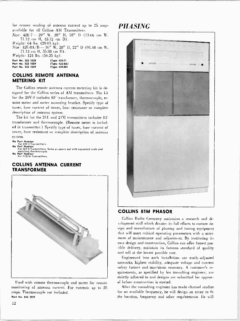
COLLINS 81M PHASOR
Collins Radio Company maintains a research and de- velopment staff which devotes its full efforts to custom de- sign and manufacture of phasing and tuning equipment that will meet critical operating parameters with a mini- mum of maintenance and adjustment. By instituting its own design and construction, Collins can offer fastest pos- sible delivery, maintain its famous standard of quality and sell at the lowest possible cost.
Engineered into each installation are easily -adjusted networks, highest stability, adequate voltage and current safety factors and maximum economy. A customer's re- quirements, as specified by his consulting engineer, are strictly adhered to and designs are submitted for approv- al before construction is started.
After the consulting engineer has made channel studies for an available frequency, he will design an array to fit
the location, frequency and other requirements. He will
12

PHASING
determine the pattern shape and size in both the vertical and horizontal planes, the maximum expected operating values of fields in both the nulls (minimum signal areas) and the lobes (maximum signal areas), the proper size, shape, height, spacing, and orientation of the antenna towers, and the phase relationships and amplitude ratios of the radiation fields of the individual antennas. This information is then submitted to the FCC with the appli- cation for a construction permit.
A Collins 81M directional antenna phasing and branch- ing system consists of: a branching circuit in which the
power is divided in precisely the amounts of power neces-
sary to give the proper ratio of fields from the individual antennas; an impedance matching circuit to match the power divider input impedance to the common point im-
pedance at which the power input is measured; phase shifting networks in series with each of the transmission lines going to the individual antenna towers; the trans- mission lines themselves; and the impedance matching network between each of the transmission lines and its associated antenna tower.
The power divider in Collins 81M equipment is usually
1:;

a resonant tank circuit consisting of a large fixed coil tapped with smaller variable coils for power adjustment. An alternate design uses a group of variable coils, each one feeding a tower; this group then becomes the tank coil of the circuit.
For 1 kw or lower, the capacitive arm of the tank cir- cuit is a capacitor and variable coil connected in series. The variable coil provides tuning adjustment by varying the over-all negative reactance in this branch of the tank. In higher powers, the tank capacitance is usually a vari- able vacuum capacitor in parallel with one or more fixed capacitors.
INPUT I INPUT I POWER I PHASE I XMSN I ANTENNA I ANT. I MATCHING 'DIVIDER' SHIFTING I LINES 1 MATCHING ,NETWORKS) INETWORKS1 ,NETWORKS
I
I I
"T` NET NET -1-
"T" NETI III
I
1 1= =
NET o NET I I -L_
I
1
I
JI "T" I` i NET NET NET 1
I -1-.i - I`T` T"
NET 1 NET
I
1
I I I
I 1
TYPICAL PHASING SYSTEM
Phase shifting networks are "T" designed, with vari- able coils mechanically connected in tandem for the series arms and a coil and capacitor in series for a shunt arm. Wherever possible, 90° networks - capable of being ad- justed ±30° from the design value - are supplied.
Wherever a phase shift network is not required, a series variable coil and capacitor are used to supply variation of ±20° around a 0° setting. They are used for trim- ming phase shift of current in the towers in which they are used.
"T" networks are also used for impedance matching at the tower base. The network has sufficient latitude of adjustment to match the transmission line impedance to any expected base operating impedance and still permit adjustment of phase shift.
Switching of circuits for day and night operation or directional and non -directional operation is accomplished by impulse -type, toggle -operated RF relays, energized by pushbutton switches on the front panel. The pushbutton automatically removes the plate voltage of the transmitter before pattern switching and restores it when switching is completed. Interlocks on the cabinet doors also remove the plate voltage when doors are opened.
Amplitude and phase controls have counters to assure accurate resetability. In complex arrays requiring addi- tional controls, the controls and counters are behind the tilt -out panel in the lower half of the cabinet.
Power dividing circuits and phase shift networks uti- lize heavy edge -wound copper ribbon inductors and ce- ramic cased mica capacitors. Vacuum capacitors are used where made necessary by high circulating currents.
Plated 5/16" copper tubing is used for all RF busses and insulation is steatite or Mycalex.
Input and output connections are provided at the top of the phasing cabinet unless otherwise specified. Special terminations are provided for solid dielectric cables in both the phasing cabinet and antenna coupling units.
An input common point RF ammeter is supplied along with line current meter jacks. Antenna current meters have make -before -break switches, which can be operated without opening the cabinet door on the weatherproof coupling units.
Extensive descriptions of typical systems are available upon request of CDS -377. Power: 1, 5 and 10 kw in 2-, 3-, 4-, 5-, and 6 -tower
arrays. Patterns: Directional day and night, same pattern; di-
rectional nighttime only; or different pattern day and night.
Size: 38" W, 76" H, 27" D (96.52 cm W, 193.04 cm H, 68.58 cm D) . (Complex Collins 81M phasing systems may require two cabinets totaling 76" W.)
No Part Number
COLLINS 564A-1 PHASE SAMPLING LOOP
Designed to sample the relative phase relationship of radio frequency energy from 550.1600 kc antenna towers
14
PHASING
in directional antenna arrays, the Collins 564A-1 is made of two loops of #10 copper wire which may be connected either in series or in parallel. The wires are contained within a loop of 7/8" painted, copper tubing which serves as an electrostatic shield.
A universal coupling permits the loop to be connected to any type of pressurized or unpressurized air or solid dielectric transmission line. The loop offers a good match to lines of 50-75 ohms impedance. A universal mounting bracket allows the loops to be mounted on any part of the antenna structure. Size: Approx. 30" W, 7' 6" H (76.2 cm W, 228.6 cm H). Weight: 50 lbs. (22.68 kg) .
Port No. 522 1518 004
COLLINS 564A-2 PHASE SAMPLING LOOP
An unshielded loop of galvanized iron pipe.
Size: Approx. 42" W, 7' 2" H (106.68 cm W, 218.44 cm H).
Weight: 35 lbs. (15.88 kg) .
Part No. 522 1519 004
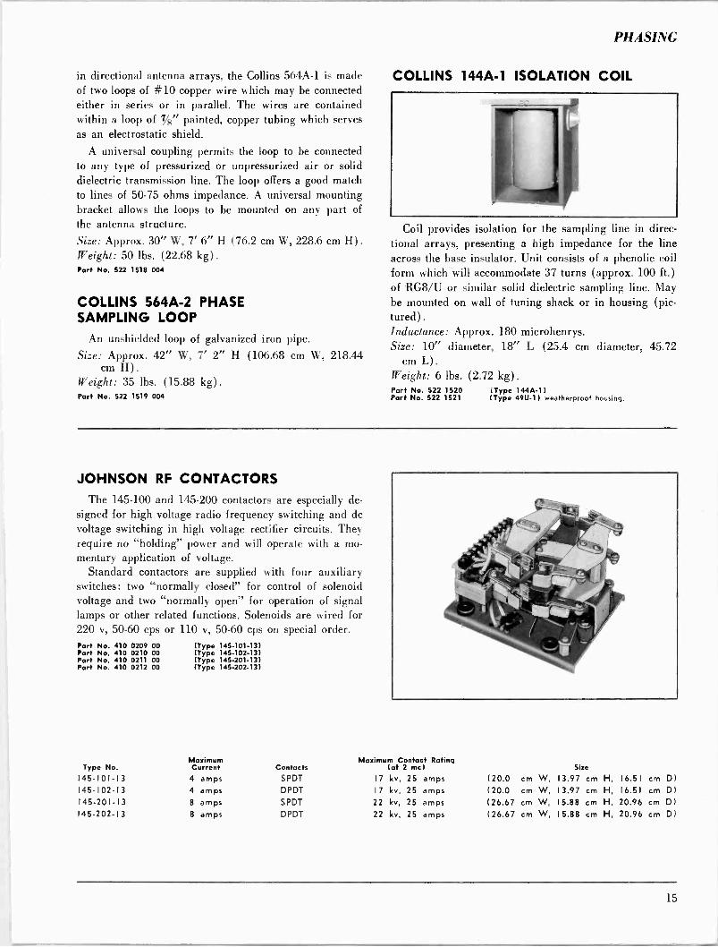
COLLINS 144A-1 ISOLATION COIL
Coil provides isolation for the sampling line in direc tional arrays, presenting a high impedance for the line across the base insulator. Unit consists of a phenolic coil form which will accommodate 37 turns (approx. 100 ft.) of RG8/U or similar solid dielectric sampling line. May be mounted on wall of tuning shack or in housing (pic- tured). Inductance: Approx. 180 microhenrys. Size: 10" diameter, 18" L (25.4 cm diameter, 45.72
cm L). Weight: 6 lbs. (2.72 kg) .
Part No. 522 1520 (Type 144A-1) Part No. 522 1521 (Type 49U-1) weatherproof housing.
JOHNSON RF CONTACTORS
The 145-100 and 145-200 contactors are especially de-
signed for high voltage radio frequency switching and do voltage switching in high voltage rectifier circuits. They require no "holding" power and will operate with a mo- mentary application of voltage.
Standard contactors are supplied with four auxiliary switches: two "normally closed" for control of solenoid voltage and two "normally open" for operation of signal lamps or other related functions. Solenoids are wired for 220 v, 50-60 cps or 110 v, 50-60 cps on special order. Part No. 410 0209 00 (Type 145-101-13) Part No. 410 0210 00 (Type 145-102-13) Part No. 410 0211 00 (Type 145-201-13) Part No. 410 0212 00 (Type 145-202-13)
Type No. Maximum Current Contacts
145-101-13 4 amps SPDT
145-102-13 4 amps DPDT 145-201-13 8 amps SPDT
145-202-13 8 amps DPDT
Maximum Contact Rating lot 2 mc)
17 kv, 25 amps 17 kv, 25 amps 22 kv, 25 amps 22 kv, 25 amps
Size
( 20.0 cm W, 13.97 cm H, 16.51 cm
( 20.0 cm W, 13.97 cm H, 16.51 cm
(26.67 cm W, 15.88 cm H, 20.96 cm
(26.67 cm W, 15.88 cm H, 20.96 cm
D1
D) D) D)
I5

FM Transmitters
FM TRANSMITTERS
WHAT'S THE MYSTERY ABOUT STEREO? The mystery of stereophonic FM broadcasting is wiped
away with the straightforward Collins approach. Not only
does Collins equipment faithfully reproduce "live" sound in both direction and dimension, it also assures the stereo broadcaster a stable system of transmission. The Collins
method of composite signal generation does away with the costly and unstable equipment needed in conventional double -injection system of stereo broadcasting.
Amplitude differences result from the directional char-
acteristics of the human ear and the baffle effect produced by the head. The time differences result from the differ-
ence in path length to each ear from a sound source which is off to one side.
To provide a realistic stereo effect, the time delay and amplitude differences between the signal received by the left and right ears must be maintained from the original sound source to the ear of the listener. The problem be-
comes one of maintaining amplitude and phase differences to provide adequate channel separation.
Left and right channels must have proper balance to
give the listener faithful reproduction of a live presenta- tion. If the source of sound moves to the left on the pro-
gram stage, the left channel's volume must increase and the right channel's volume decrease proportionately to
convey accurately the change of direction of the sound source.
Adequate channel separation - at least 30 db - must be maintained. Lack of adequate separation would permit "bleeding" of one channel's sound into the other, thus moving the sound source to an apparent center from the listener's point of view.
Finally, compatibility is required. The transmitted stereo signal must be capable of being received not only
by the stereo FM receiver, but by existing monaural re-
ceivers as well. To comply with FCC requirements, a signal which
can be received by monaural receivers must be trans- mitted. This signal is the combination of the left and right channels, or L + R. To achieve stereo broadcasting, a subcarrier FM signal provides the vehicle for the third dimensional sound. This is the L-R channel.
The Collins 786M-1 FM Stereo Multiplex Generator achieves this L-R signal by a mathematical system of
time division. More of this later. Basically, then, the
stereo FM receiver gets two signals, an L + R and an L- R. To feed the left channel and the receiver's left speaker, the receiver adds the L + R and L-R signals and derives 2L. The same process by subtraction yields 2R in the
right speaker. Since the figure 2 represents a volume
control setting, the receiver in effect recovers the L and R
sound originally produced at the left and right micro-
phones on the program stage. Returning to the time division principle, it is this factor
which makes the Collins Stereo Generator a standout unit in operation and maintenance. In the conventional stereo
generation system, two channels are required to feed
L + R and L-R to the exciter. This technique, known as
matrixing, requires gain and phase shift between the two
channels be maintained within close tolerances to main-
tain adequate channel separation throughout the system.
Collins' new approach eliminates the need for continual
surveillance of time delay shifting between the two chan-
nels by eliminating the double -injection system entirely. Instead, the direct FM wide band exciter is fed a
single, composite signal on one wire. Any shift in gain
or phase will affect both channels equally, thus maintain-
ing the 35 db channel separation. Not only does this as-
sure the broadcaster an inherently stable method of stereo
transmission, but greatly simplifies both operation and
maintenance. The rather expensive matrix networks needed in the
dual channel system are eliminated as are the time delay
switches needed to match the channels when a shift in
gain or phase occurs. The Collins time division system of stereo signal gen-
eration is nothing more than a sampling at a 38 kc rate
of left and right audio inputs. The output from the switch
is equivalent to L + R plus the L-R double sideband components centered on the switching frequency (38 kc)
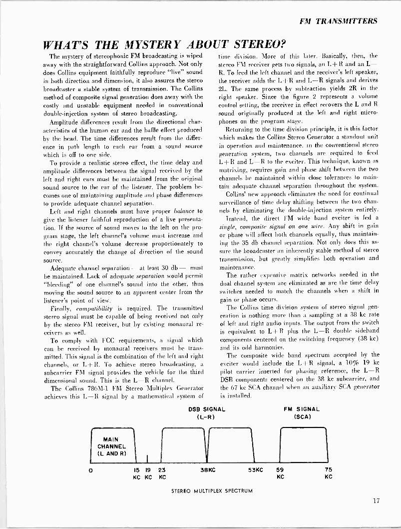
and its odd harmonics. The composite wide band spectrum accepted by the
exciter would include the L + R signal, a 10% 19 kc
pilot carrier inserted for phasing reference, the L-R DSB components centered on the 38 kc subcarrier, and
the 67 kc SCA channel when an auxiliary SCA generator is installed.
DSB SIGNAL (L-R)
MAIN CHANNEL (L AND R)
0 15 19 23 38 KC
KC KC KC
FM SIGNAL (SCA)
in 53KC 59 75
KC KC
STEREO MULTIPLEX SPECTRUM
17
0108 281285
110
MX OUTPUT 75 Wed
38 KC OSC 75 N1N
KC SUP 5 YIN
AWN 38 KC DRIVER 00 gvUR ollUt
AUDIO ADD 10.
METER
9 KCSLyQOSC
0108 2811155
21,81758
CONTROL
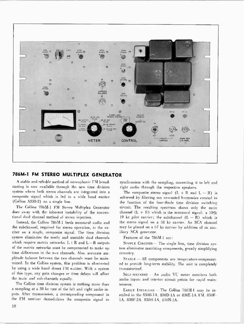
786M-1 FM STEREO MULTIPLEX GENERATOR A stable and reliable method of stereophonic FM broad-
casting is now available through the new time division system where both stereo channels are integrated into a composite signal which is fed to a wide band exciter (Collins A830-2) on a single line.
The Collins 786M-1 FM Stereo Multiplex Generator does away with the inherent instability of the conven- tional dual channel method of stereo injection.
Instead, the Collins 786M-1 feeds monaural audio and the subchannel, required for stereo operation, to the ex- citer on a single, composite signal. The time division system eliminates the costly and unstable dual channels which require matrix networks. L + R and L-R outputs of the matrix networks must be compensated to make up time differences in the two channels. Also, accurate am- plitude balance between the two channels must be main- tained. In the Collins system, this problem is eliminated by using a wide band direct FM exciter. With a system of this type, any gain changes or time delays will affect the main and sub -channels equally.
The Collins time division system is nothing more than a sampling at a 38 kc rate of the left and right audio in- puts. After transmission, a corresponding component in the FM receiver demodulates the composite signal in
OFF LEVEL
PILOT CHAN SEP CARRIER L.R AMPL
synchronism with the sampling, converting it to left and right audio through the respective speakers.
The composite stereo signal (L -}- R and L - R) is achieved by filtering out unwanted harmonics created in the function of the four -diode time division switching circuit. The resulting spectrum shows only the main channel (L R) which is the monaural signal; a 10% 19 kc pilot carrier; the subchannel (L - R) which is the stereo signal on a 38 kc carrier. An SCA channel may be placed on a 67 kc carrier by addition of an aux- iliary SCA generator.
Features of the 786M-1 are: SIMPLE CIRCUITS - The single line, time division sys-
tem eliminates matrixing components, greatly simplifying circuitry.
STABLE - All components are temperature -compensat- ed to provide long-term stability. The unit is completely transistorized.
SELF -METERED - An audio VU meter monitors both audio inputs and interior circuit points for rapid main- tenance.
EASILY INSTALLED - The Collins 786M-1 may be in- stalled in the 830B -1A, 830D -1A or 830E -1A FM, 830E - 1A, 830F -2A, 830H -1A, 830N -1A.
18
FM TRANSMITTERS
L AUDIO
R AUDIO
PRE -EMPHASIS NETWORK
38 KC OSCILLATOR
PRE -EMPHASIS NETWORK
38KC BUFFER
HI-PASS FIL 8 60011 -60011
XFMR
HI-PASS FIL 8 60011 -60011
XMFR
I5KC LP FILTER
38 KC DRIVER
I5KC LP FILTER
EMITTER FOL LOWER
EMITTER FOLLOWER
SWITCH
EMITTER FOLLOWER
53KC LOW-PASS LINEAR PH FIL
TP701
PILOT 1
PHASE
19 KC LOCKED
OSCILLATOR
PI LOT OFF -ON
OUTPUT 50CPS
TO 53KC
PILOT AM
A TP702
BLOCK DIAGRAM 786M -I
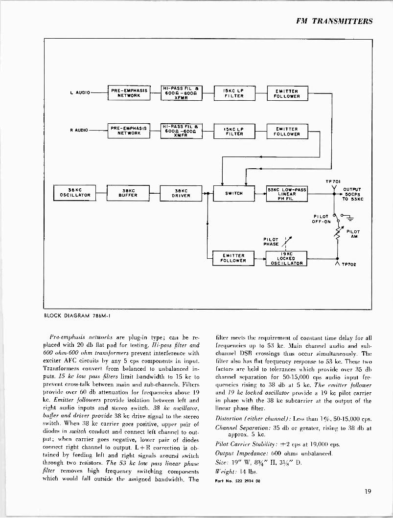
Pre -emphasis networks are plug-in type; can be re- placed with 20 db flat pad for testing. Hi -pass filter and 600 ohm -600 ohm transformers prevent interference with exciter AFC circuits by any 5 cps components in input. Transformers convert from balanced to unbalanced in- puts. 15 kc low pass filters limit bandwidth to 15 kc to prevent cross -talk between main and sub -channels. Filters provide over 60 db attenuation for frequencies above 19 kc. Emitter followers provide isolation between left and right audio inputs and stereo switch. 38 kc oscillator, buffer and driver provide 38 kc drive signal to the stereo switch. When 38 kc carrier goes positive, upper pair of diodes in switch conduct and connect left channel to out- put; when carrier goes negative, lower pair of diodes connect right channel to output. L -F R correction is ob- tained by feeding left and right signals around switch through two resistors. The 53 kc low pass linear phase filter removes high frequency switching components which would fall outside the assigned bandwidth. The
filter meets the requirement of constant time delay for all frequencies up to 53 kc. Main channel audio and sub - channel DSB crossings thus occur simultaneously. The filter also has flat frequency response to 53 kc. These two factors are held to tolerances which provide over 35 db channel separation for 50-15,000 cps audio input fre- quencies rising to 38 db at 5 kc. The emitter follower and 19 kc locked oscillator provide a 19 kc pilot carrier in phase with the 38 kc subcarrier at the output of the linear phase filter.
Distortion (either channel): Less than 1%, 50-15,000 cps.
Channel Separation: 35 db or greater, rising to 38 db at approx. 5 kc.
Pilot Carrier Stability: ±2 cps at 19,000 cps.
Output Impedance: 600 ohms unbalanced. Size: 19" W, 83/4" H, 31/8" D.
Weight: 14 lbs.
Part No. 522 2914 00
19

MONO OR
STEREO INPUT
DC
CONTROL
MOD
14MC
DISCR
-I AUDIO FEEDBACK
GATE FILTER
5CPS KEY GATE
I4MC REF
DISCR AMPL
1
SYNC DET
BAL MIXER
74- 94MC OSC
PA 10 WATTS - MIN OF RF
OUTPUT
BLOCK DIAGRAM A830-2
COLLINS A830-2 10 -WATT DIRECT FM EXCITER
An ideal, independent unit that may be used in edu- cational stations or for other similar low power applica-
tions, the Collins A830-2 is a 10 -watt direct FM exciter that accepts audio inputs from a monophonic, stereo (see Collins FM Stereo Multiplex Generator description, or SCA source by telephone lines or direct connection and modulates an existing carrier to provide an RF drive signal for direct transmission or further amplification. The unit serves as the exciter portion of the Collins 830B- lA and 830E -1A FM Transmitters (see descriptions) and may be rack mounted in 10 -watt installations. Power Source: 117 v ac ±5%, 50-60 cps, single phase. Power Supply Voltages:
+20 v dc ±0.1 v, regulation ±0.1 v; ripple 0.5%. -10 v dc ±0.1 v, regulation ±0.1 v; ripple 0.5%. + 300 v dc ±5.0 v, regulation ±10 v; ripple 1%.
Carrier Frequency Stability: Not more than ±2,000 cps. FM Noise Level: 65 db below 100% modulation (±75
kc). AM Noise Level (RMS) : 55 db below 100% AM level. Tube Complement (one each):
6U8 6AU6 12AT7 5763
2E26 Size: 19" W, 261/4" H, 33/8" D (48.26 cm W, 66.68 cm
H, 8.57 cm D) .
Weight: 42 lbs. (19.05 kg) .
Part No. 522 2714 Consists of 10 -watt exciter, set of tubes, transistors, power rectifiers, crystal and instruction book. Rack mounted unit.
No Part Number Complete set of spare tubes, plug-in transistors plus power rectifiers for 830A-2.
No Part Number FCC set of spare tubes, plug-in transistors plus power rectifiers for 830A-2.
No Part Number Spare crystal operating freauency for A830-2 10 -watt exciter.
Part No. 289 2743 00 Spare 14 me crystal.
20
FM TRANSMITTERS
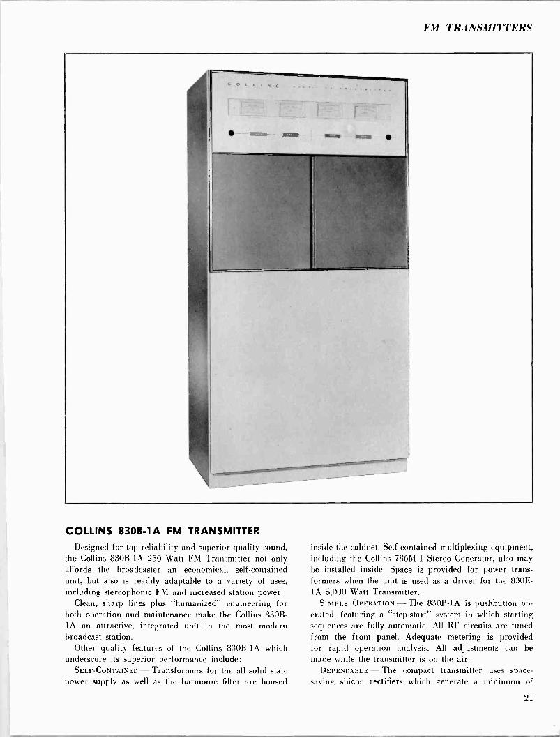
COLLINS 830B -1A FM TRANSMITTER
Designed for top reliability and superior quality sound, the Collins 830B -1A 250 Watt FM Transmitter not only affords the broadcaster an economical, self-contained unit, but also is readily adaptable to a variety of uses, including stereophonic FM and increased station power.
Clean, sharp lines plus "humanized" engineering for both operation and maintenance make the Collins 830B- lA an attractive, integrated unit in the most modern broadcast station.
Other quality features of the Collins 830B -1A which underscore its superior performance include: SELF-CONTAINED - Transformers for the all solid state
power supply as well as the harmonic filter are housed
inside the cabinet. Self-contained multiplexing equipment, including the Collins 786M-1 Stereo Generator, also may be installed inside. Space is provided for power trans- formers when the unit is used as a driver for the 830E- lA 5,000 Watt Transmitter.
SIMPLE OPERATION - The 830B -1A is pushbutton op- erated, featuring a "step -start" system in which starting sequences are fully automatic. All RF circuits are tuned from the front panel. Adequate metering is provided for rapid operation analysis. All adjustments can be made while the transmitter is on the air. DEPENDABLE - The compact transmitter uses space -
saving silicon rectifiers which generate a minimum of
21
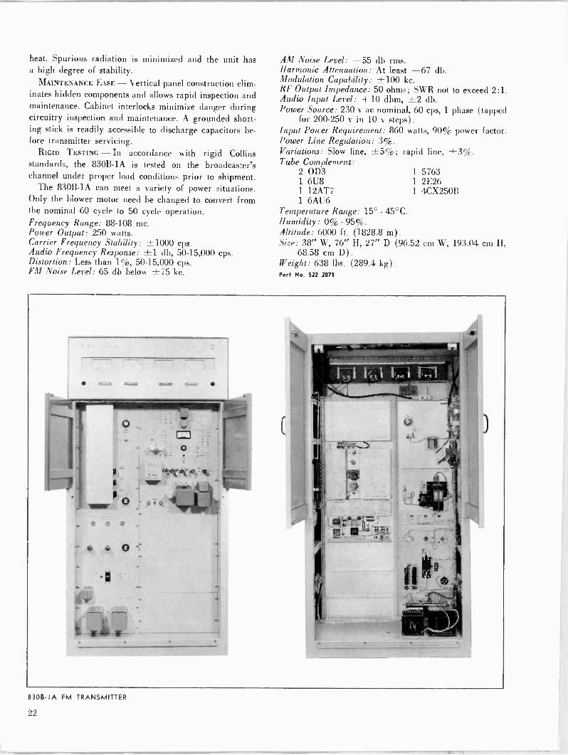
heat. Spurious radiation is minimized and the unit has a high degree of stability.
MAINTENANCE EASE - Vertical panel construction elim- inates hidden components and allows rapid inspection and maintenance. Cabinet interlocks minimize danger during circuitry inspection and maintenance. A grounded short- ing stick is readily accessible to discharge capacitors be- fore transmitter servicing.
RIGID TESTING - In accordance with rigid Collins standards, the 830B -1A is tested on the broadcaster's channel under proper load conditions prior to shipment.
The 830B -1A can meet a variety of power situations. Only the blower motor need be changed to convert from the nominal 60 cycle to 50 cycle operation. Frequency Range: 88-108 mc. Power Output: 250 watts. Carrier Frequency Stability: ±1000 cps. Audio Frequency Response: ±1 db, 50-15,000 cps. Distortion: Less than 1%, 50-15,000 cps. FM Noise Level: 65 db below ±75 kc.
AM Noise Level: -55 db rms. Harmonic Attenuation: At least -67 db. Modulation Capability: ±100 kc. RF Output Impedance: 50 ohms; SWR not to exceed 2:1. Audio Input Level: +10 dbm, ±2 db. Power Source: 230 v ac nominal, 60 cps, 1 phase (tapped
for 200-250 v in 10 AT steps). Input Power Requirement: 860 watts, 90% power factor. Power Line Regulation: 3%. Variations: Slow line, ±5%; rapid line, ±3%. Tube Complement:
2 OD3 1 5763 1 6U8 1 2E26 1 12AT7 1 4CX250B 1 6AU6
Temperature Range: 15° - 45°C. Humidity: 0% - 95%. Altitude: 6000 ft. (1828.8 m) .
Size: 38" W, 76" H, 27" D (96.52 cm W, 193.04 cm H, 68.58 cm D) .
Weight: 638 lbs. (289.4 kg) .
Part No. 522 2871
0 0 0
8308 -IA FM TRANSMITTER
FM TRANSMITTERS
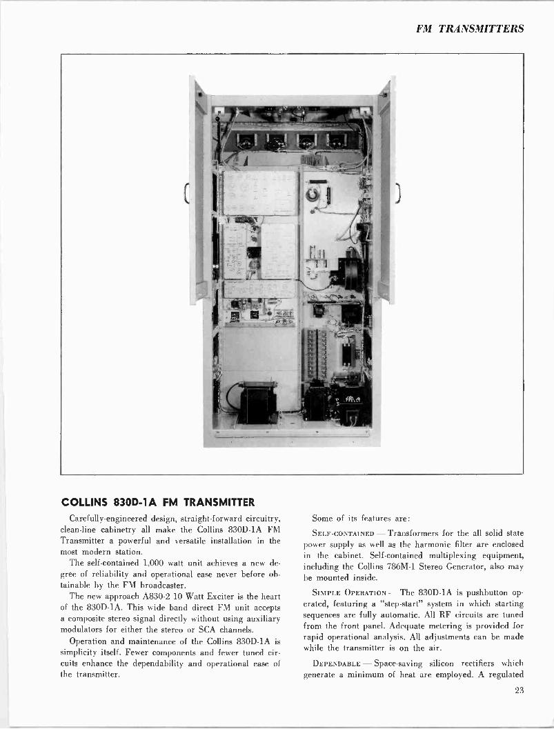
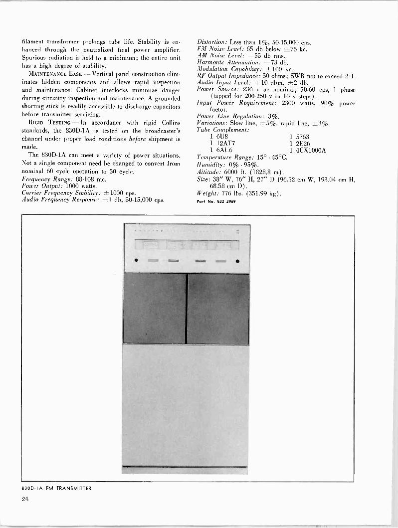
COLLINS 830D -1A FM TRANSMITTER
Carefully -engineered design, straight -forward circuitry, clean -line cabinetry all make the Collins 830D -1A FM Transmitter a powerful and versatile installation in the most modern station.
The self-contained 1,000 watt unit achieves a new de- gree of reliability and operational ease never before ob- tainable by the FM broadcaster.
The new approach A830-2 10 Watt Exciter is the heart of the 830D -1A. This wide band direct FM unit accepts a composite stereo signal directly without using auxiliary modulators for either the stereo or SCA channels.
Operation and maintenance of the Collins 830D -1A is simplicity itself. Fewer components and fewer tuned cir- cuits enhance the dependability and operational ease of the transmitter.
Some of its features are:
SELF-coNTAINED - Transformers for the all solid state power supply as well as the harmonic filter are enclosed in the cabinet. Self-contained multiplexing equipment, including the Collins 786M-1 Stereo Generator, also may be mounted inside.
SIMPLE OPERATION - The 830D -1A is pushbutton op-
erated, featuring a "step -start" system in which starting sequences are fully automatic. All RF circuits are tuned from the front panel. Adequate metering is provided for rapid operational analysis. All adjustments can be made while the transmitter is on the air.
DEPENDABLE - Space -saving silicon rectifiers which generate a minimum of heat are employed. A regulated
23
filament transformer prolongs tube life. Stability is en- hanced through the neutralized final power amplifier. Spurious radiation is held to a minimum; the entire unit has a high degree of stability.
MAINTENANCE EASE - Vertical panel construction elim- inates hidden components and allows rapid inspection and maintenance. Cabinet interlocks minimize danger during circuitry inspection and maintenance. A grounded shorting stick is readily accessible to discharge capacitors before transmitter servicing.
RIGID TESTING - In accordance with rigid Collins standards, the 830D -1A is tested on the broadcaster's channel under proper load conditions before shipment is made. -
The 830D -1A can meet a variety of power situations. Not a single component need be changed to convert from nominal 60 cycle operation to 50 cycle. Frequency Range: 88.108 mc. Power Output: 1000 watts. Carrier Frequency Stability: ±1000 cps. Audio Frequency Response: ±1 db, 50-15,000 cps.
830D -IA FM TRANSMITTER
Distortion: Less than 1%, 50-15,000 cps. FM Noise Level: 65 db below ±75 kc. AM Noise Level: -55 db rms. Harmonic Attenuation: -73 db. Modulation Capability: ±100 kc. RF Output Impedance: 50 ohms; SWR not to exceed 2:1. Audio Input Level: +10 dbm, ±2 db. Power Source: 230 v ac nominal, 50-60 cps, 1 phase
(tapped for 200-250 v in 10 v steps). Input Power Requirement: 2300 watts, 90% power
factor. Power Line Regulation: 3%. Variations: Slow line, ±5%, rapid Tube Complement:
1 6U8 1
1 12AT7 1
1 6AU6 1
Temperature Range: 15° - 45°C. Humidity: 0% - 95%. Altitude: 6000 ft. (1828.8 m) . Size: 38" W, 76" H, 27" D (96.52
68.58 cm D) .
W eight: 776 lbs. (351.99 kg) .
Part No. 522 2969
line, ±3%.
5763 2E26 4CX1000A
cm W, 193.04 cm H,
21
FM TRANSMITTERS
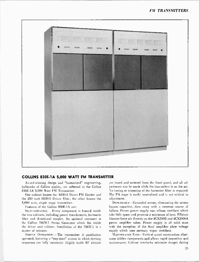
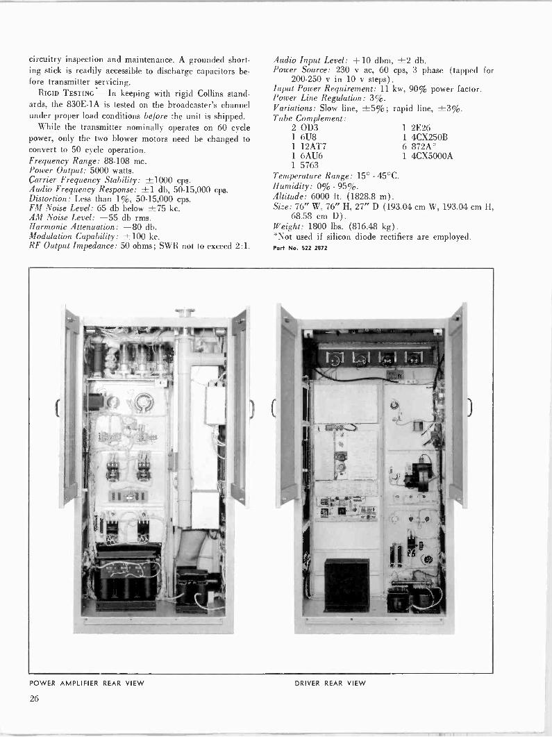
COLLINS 830E -1A 5,000 WATT FM TRANSMITTER
Award -winning design and "humanized" engineering, hallmarks of Collins quality, are reflected in the Collins 830E -1A 5,000 Watt FM Transmitter.
One cabinet houses the A830-2 Direct FM Exciter and the 250 watt B830-1 Driver Unit; the other houses the 5,000 watt, single stage transmitter.
Features of the Collins 830E -1A are: SELF-CONTAINED - Every component is housed inside
the two cabinets, including power transformers, harmonic filter and directional coupler. An optional accessory is the Collins 786M-1 Stereo Generator which fits inside the driver unit cabinet. Installation of the 786M-1 is a matter of minutes.
SIMPLE OPERATION - The transmitter is pushbutton operated, featuring a "step -start" system in which starting sequences are fully automatic. Highly stable RF circuits
are tuned and metered from the front panel, and all ad- justments can be made while the transmitter is on the air. No tuning or trimming of the harmonic filter is required. The PA stage is easily neutralized and is not critical in adjustment.
DEPENDABLE-Grounded screen, eliminating the screen bypass capacitor, does away with a common source of failure. Driver power supply uses silicon rectifiers which take little space and generate a minimum of heat. Efficient blowers force air directly on the 4CX250B and 4CX5000A power amplifier tubes. Power supply is all solid state with the exception of the final amplifier plate voltage supply which uses mercury vapor rectifiers. MAINTENANCE EASE-Vertical panel construction elimi-
nates hidden components and allows rapid inspection and maintenance. Cabinet interlocks minimize danger during
25
circuitry inspection and maintenance. A grounded short- ing stick is readily accessible to discharge capacitors be- fore transmitter servicing.
RIGID TESTING - In keeping with rigid Collins stand- ards, the 830E -1A is tested on the broadcaster's channel under proper load conditions be/ore the unit is shipped.
While the transmitter nominally operates on 60 cycle power, only the two blower motors need be changed to convert to 50 cycle operation. Frequency Range: 88-108 mc. Power Output: 5000 watts. Carrier Frequency Stability: ±1000 cps. Audio Frequency Response: ±1 db, 50-15,000 cps. Distortion: Less than 1%, 50-15,000 cps. FM Noise Level: 65 db below ±75 kc. AM Noise Level: -55 db rms. Harmonic Attenuation: -80 db. Modulation Capability: ±100 kc. RF Output Impedance: 50 ohms; SWR not to exceed 2:1.
Audio Input Level: +10 dbm, ±2 db. Power Source: 230 v ac, 60 cps, 3 phase (tapped for
200-250 v in 10 v steps). Input Power Requirement: 11 kw, 90% power factor. Power Line Regulation: 3%. Variations: Slow line, ±5%; rapid line, ±3%. Tube Complement:
2 OD3 1 6U8 1 12AT7 1 6AU6 1 5763
Temperature Range: 15° - 45°C. Humidity: 0% - 95%. Altitude: 6000 ft. (1828.8 m) .
Size: 76" W, 76" H, 27" D (193.04 cm W, 193.04 cm H, 68.58 cm D) .
Weight: 1800 lbs. (816.48 kg) .
*Not used if silicon diode rectifiers are employed. Part No. 522 2872
1 2E26 1 4CX250B 6 872A* 1 4CX5000A
POWER AMPLIFIER REAR VIEW DRIVER REAR VIEW
26
FM TRANSMITTERS
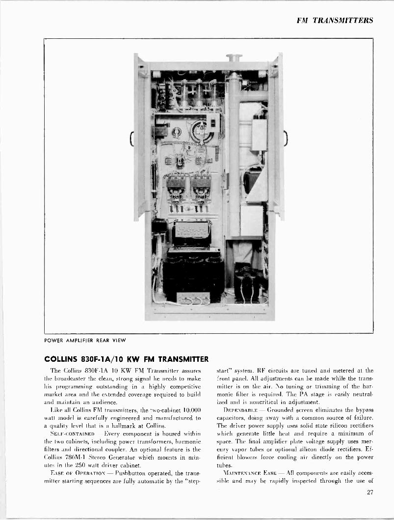
POWER AMPLIFIER REAR VIEW
COLLINS 830F -1A/10 KW FM TRANSMITTER
The Collins 830F -1A 10 KW FM Transmitter assures the broadcaster the clean, strong signal he needs to make his programming outstanding in a highly competitive market area and the extended coverage required to build and maintain an audience.
Like all Collins FM transmitters, the two -cabinet 10,000 watt model is carefully engineered and manufactured to a quality level that is a hallmark at Collins.
SELF-CONTAINED - Every component is housed within the two cabinets, including power transformers, harmonic filters and directional coupler. An optional feature is the Collins 786M-1 Stereo Generator which mounts in min- utes in the 250 watt driver cabinet.
EASE OF OPERATION - Pushbutton operated, the trans- mitter starting sequences are fully automatic by the "step -
start" system. RF circuits are tuned and metered at the front panel. All adjustments can be made while the trans- mitter is on the air. No tuning or trimming of the har- monic filter is required. The PA stage is easily neutral- ized and is noncritical in adjustment. DEPENDABLE - Grounded screen eliminates the bypass
capacitors, doing away with a common source of failure. The driver power supply uses solid state silicon rectifiers which generate little heat and require a minimum of space. The final amplifier plate voltage supply uses mer- cury vapor tubes or optional silicon diode rectifiers. Ef-
ficient blowers force cooling air directly on the power tubes. MAINTENANCE EASE - All components are easily acces-
sible and may be rapidly inspected through the use of
27

POWER AMPLIFIER FRONT VIEW
vertical panels. All panels are interlocked for safety; a grounded shorting stick is provided.
RIGID TESTING - In keeping with rigid Collins stand- ards, the transmitter is tested under actual load conditions on the broadcaster's channel before the unit is shipped.
While the transmitter is designed for 60 cycle opera- tion, only the blower motors and plate contactors need be changed for 50 cycle use.
Collins also manufactures the 830F -2A transmitter. This unit uses an 830D -1A 1,000 watt driver, required when the additional PA is installed for 20,000 watt op- eration. If an eventual increase to 20KW is planned, the 830F -2A should be installed initially. Frequency Range: 88-108 mc. Power Output: 3,000-10,000 watts nominal. Carrier Frequency Stability: ±1,000 cps. Audio Frequency Response: ± 1 db, 50-15,000 cps. Distortion: Less than 1%, 50-15,000 cps. FM Noise Level: 65 db below ±75 kc. AM Noise Level: -55 db rms. Harmonic Attenuation: -80 db.
Modulation Capability: ±100 kc. RF Output Impedance: 50 ohms; SWR not to exceed 2:1. Audio Input Level: +10 dbm, ±2 db. Power Source: 230 v ac, cps (50 cps optional), 3 phase
(tapped for 200-250 v in 10 IT steps). Input Power Requirement: 20 kw, 90% power factor. Power Line Regulation: 370. Variations: Slow line, ±5%; rapid line, ±370. Tube Complement:
2 OD3 1 6AU6 1 4CX250B 1 6U8 1 5763 6 872A* 1 12AT7 1 2E26 1 4CX5000A
Temperature Range: 20°-45°C with mercury vapor rec- tifiers. 10°-45°C with silicon diode rectifiers.
Humidity: 070-9570. Altitude: 6,000 ft. (1828.8 m) . Size: 76" W, 76" H, 27" D (193 cm W, 193 cm H, 68.6
cm D). Weight: 1,900 lbs. (861.8 kg) .
*Not used if silicon rectifiers are employed. Part No. 522 3054 (Type 830F -1A) Port No. 522 3139 (Type 830F -2A)
28
FM TRANSMITTERS
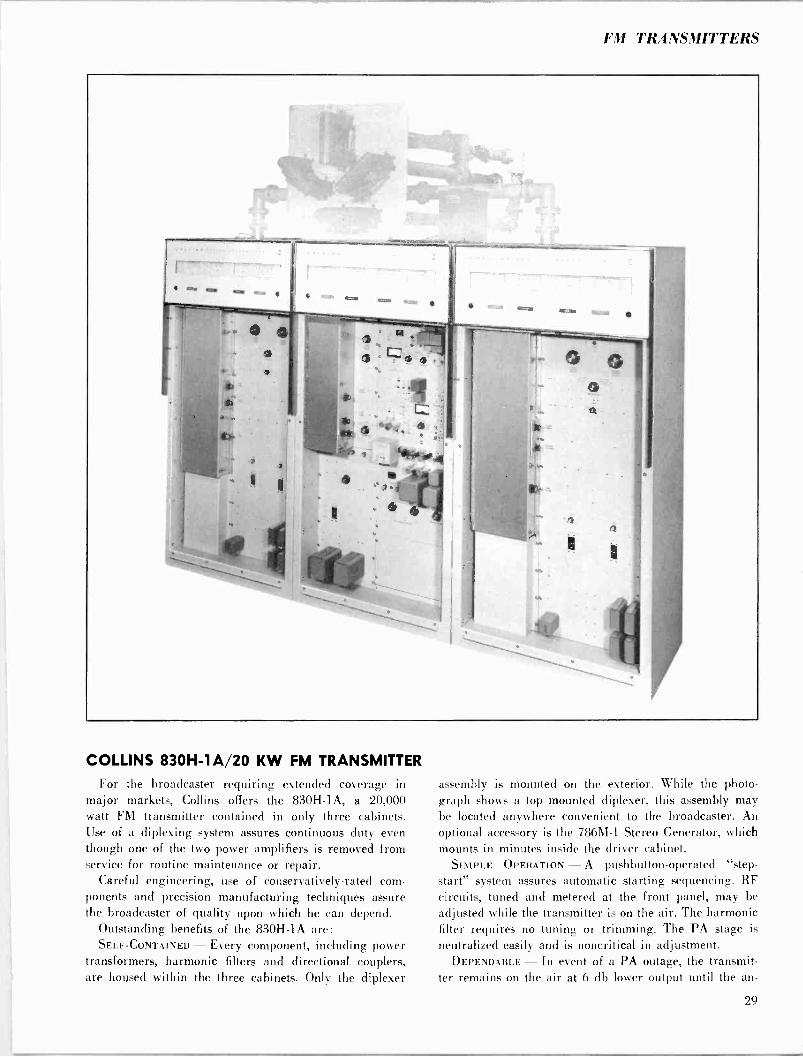
COLLINS 830H -1A/20 KW FM TRANSMITTER For the broadcaster requiring extended coverage in
major markets, Collins offers the 830H -1A, a 20,000 watt FM transmitter contained in only three cabinets. Use of a diplexing system assures continuous duty even though one of the two power amplifiers is removed from service for routine maintenance or repair.
Careful engineering, use of conservatively -rated com- ponents and precision manufacturing techniques assure the broadcaster of quality upon which he can depend.
Outstanding benefits of the 830H -1A are: SELF-CONTAINED - Every component, including power
transformers, harmonic filters and directional couplers, are housed within the three cabinets. Only the diplexer
assembly is mounted on the exterior. While the photo- graph shows a top mounted diplexer, this assembly may be located anywhere convenient to the broadcaster. An optional accessory is the 786M-1 Stereo Generator, which mounts in minutes inside the driver cabinet.
SIMPLE OPERATION -A pushbutton -operated "step - start" system assures automatic starting sequencing. RF circuits, tuned and metered at the front panel, may be adjusted while the transmitter is on the air. The harmonic filter requires no tuning or trimming. The PA stage is
neutralized easily and is noncritical in adjustment. DEPENDABLE - In event of a PA outage, the transmit-
ter remains on the air at 6 db lower output until the an -
29

tenna is patched to one amplifier to permit half -power (-3 db) operation while the disabled PA is being re- stored to service. The transmitter is not off the air during this operation. A grounded screen eliminates the bypass capacitors, common trouble points. Independent driver power supply is solid state, requiring little space and gen- erating little heat. The PA power supply consists of mer- cury vapor tubes, with a solid state supply an optional feature. Efficient, quiet blowers force air directly on the 4CX1000A and two 4CX5000A power amplifier tubes.
MAINTENANCE EASE - All components are easily acces- sible for inspection and maintenance through vertical panel construction. All cabinet panels are interlocked for safety; a grounded shorting stick is installed in each cab- inet to discharge capacitors before servicing.
RIGID TESTING - The 830H -1A, like all Collins trans- mitters, is tested on the broadcaster's channel under ac- tual load conditions be/ore shipment.
While the transmitter nominally operates on 60 cycles, only the blower motors and plate contactors need be changed for 50 cycle operation. Frequency Range: 88-108 mc. Power Output: 6,000-20,000 watts nominal. Carrier Frequency Stability: -±1,000 cps. Audio Frequency Response: ±1 db, 50-15,000 cps. Distortion: Less than 1%, 50-15,000 cps. FM Noise Level: 65 db below ± 75 kc. AM Noise Level: -55 db rms. Harmonic Attenuation: -80 db.
Modulation Capability: ±100 kc. RF Output Impedance: 50 ohms; SWR not to exceed 2:1. Audio Input Level: + 10 dbm, ±2 db. Power Source: 230 v ac, 60 cps (50 cps optional), 3
phase (tapped for 200-250 v in 10 v steps). Input Power Requirement: 40 kw, 90% power factor. Power Line Regulation: 3%. Variations: Slow line, ±5%; rapid line, ±3%. Tube Complement:
1 6U8 1 2E26 1 12AT7 1 4CX1000A 1 6AU6 12 872A* 1 5763 2 4CX5000A
Temperature Range: 20° - 45°C with mercury vapor rec- tifiers; 10° - 45°C with silicon diode rectifiers.
Humidity: 0% - 95%. Altitude: 6,000 ft. (1828.8 m) .
Size: 114" W, 76" H, 27" D (289.6 cm W, 193 cm H, 68.6 cm D).
Weight: 2,900 lbs. (1315 kg) .
*Not used if silicon diode rectifiers are employed. Part No. 522 3055
830N -1A FM TRANSMITTER
For the broadcaster whose market includes extensive mobile reception, Collins sells the 830N -1A, a dual 10,000 watt transmitter. This unit transmits 10,000 watts through vertically polarized antennas for automobile receivers and 10.000 watts to the horizontally -polarized antennas for home receivers. Part No. 522 3592
830H- IA FM TRANSMITTER

Antennas, Towers, Transmission Lines
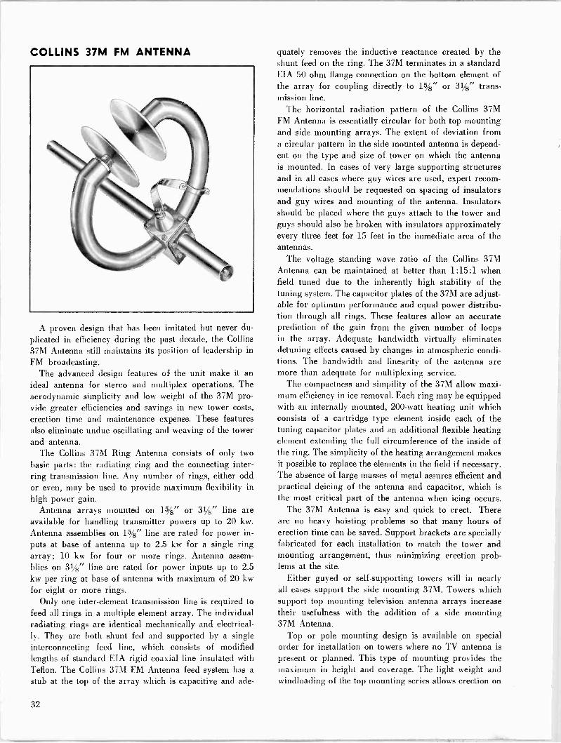
COLLINS 37M FM ANTENNA
A proven design that has been imitated but never du-
plicated in efficiency during the past decade, the Collins 37M Antenna still maintains its position of leadership in FM broadcasting.
The advanced design features of the unit make it an ideal antenna for stereo and multiplex operations. The aerodynamic simplicity and low weight of the 37M pro- vide greater efficiencies and savings in new tower costs, erection time and maintenance expense. These features also eliminate undue oscillating and weaving of the tower and antenna.
The Collins 37M Ring Antenna consists of only two basic parts: the radiating ring and the connecting inter- ring transmission line. Any number of rings, either odd or even, may be used to provide maximum flexibility in high power gain.
Antenna arrays mounted on 15/8" or 31/8" line are available for handling transmitter powers up to 20 kw.
Antenna assemblies on 15/8" line are rated for power in-
puts at base of antenna up to 2.5 kw for a single ring array; 10 kw for four or more rings. Antenna assem- blies on 31/8" line are rated for power inputs up to 2.5 kw per ring at base of antenna with maximum of 20 kw for eight or more rings.
Only one inter -element transmission line is required to feed all rings in a multiple element array. The individual radiating rings are identical mechanically and electrical- ly. They are both shunt fed and supported by a single interconnecting feed line, which consists of modified lengths of standard EIA rigid coaxial line insulated with Teflon. The Collins 37M FM Antenna feed system has a
stub at the top of the array which is capacitive and ade-
quately removes the inductive reactance created by the shunt feed on the ring. The 37M terminates in a standard EIA 50 ohm flange connection on the bottom element of the array for coupling directly to 15/8" or 31/8" trans- mission line.
The horizontal radiation pattern of the Collins 37M FM Antenna is essentially circular for both top mounting and side mounting arrays. The extent of deviation from a circular pattern in the side mounted antenna is depend- ent on the type and size of tower on which the antenna is mounted. In cases of very large supporting structures and in all cases where guy wires are used, expert recom- mendations should be requested on spacing of insulators and guy wires and mounting of the antenna. Insulators should be placed where the guys attach to the tower and guys should also be broken with insulators approximately every three feet for 15 feet in the immediate area of the antennas.
The voltage standing wave ratio of the Collins 37M Antenna can be maintained at better than 1:15:1 when field tuned due to the inherently high stability of the tuning system. The capacitor plates of the 37M are adjust- able for optimum performance and equal power distribu- tion through all rings. These features allow an accurate prediction of the gain from the given number of loops in the array. Adequate bandwidth virtually eliminates detuning effects caused by changes in atmospheric condi- tions. The bandwidth and linearity of the antenna are more than adequate for multiplexing service.
The compactness and simpility of the 37M allow maxi- mum efficiency in ice removal. Each ring may be equipped with an internally mounted, 200 -watt heating unit which consists of a cartridge type element inside each of the tuning capacitor plates and an additional flexible heating element extending the full circumference of the inside of the ring. The simplicity of the heating arrangement makes it possible to replace the elements in the field if necessary. The absence of large masses of metal assures efficient and practical deicing of the antenna and capacitor, which is the most critical part of the antenna when icing occurs.
The 37M Antenna is easy and quick to erect. There are no heavy hoisting problems so that many hours of erection time can be saved. Support brackets are specially fabricated for each installation to match the tower and mounting arrangement, thus minimizing erection prob- lems at the site.
Either guyed or self-supporting towers will in nearly all cases support the side mounting 37M. Towers which support top mounting television antenna arrays increase their usefulness with the addition of a side mounting 37M Antenna.
Top or pole mounting design is available on special order for installation on towers where no TV antenna is present or planned. This type of mounting provides the maximum in height and coverage. The light weight and windloading of the top mounting series allows erection on
32
ANTENNAS
most guyed and self-supporting towers without extensive tower modification.
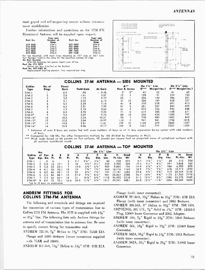
Further information and quotations on the 37M FM Directional Antenna will be supplied upon request.
Type and Type and Part No. Number of Part No. Number of
Rings Rings 013 0020 37M-1 013 0070 37M-6 013 0030 37M-2 013 0080 37M-7 013 0040 37M-3 013 0090 37M-8 013 0050 37M-4 097 1693 37M -I0 013 0060 37M-5 097 1528 37M-12
For top mounted, with mast rings mounted on 15/s" Line or 3'/a" Line, Part Number remains the same for the specified number of rings. No Part Number
37M FM Antennas for power inputs over 20 kw. Part No. 013 0099
Deicer per bay installed at the factory..
Part No. 099 0005 00 Replacement heating element. Two required per ring.
PROFESS AM ClAu111V1.1.1. RP. ANS.. [OR SIOUNTIREG
ON SOw. sessUGEOEURER ASP
SUIPOR
a
OR GU
G MATCHING G,
4
OlutRE
GUISE GAUGE SOCCET SOR
GOGNEING SOU ORE TOWN SY
.10.0.0 ao NOSISE
Collins Type
No. of Rings
COLLINS 37-M Power Gain Field Gain
ANTENNA - SIDE MOUNTED A** On 15/e" Line
db Gain Feet & Inches B*** Weight(lbs.) On 31/e" Line
B*** Weight(Ibs.) 37M -I I 0.9 .95 - 0.45 2' 5" 43 42 81 69
37M-2 2 2.0 1.41 3.01 12 3 125 91 234 155
37M-3 3 3.0 1.73 4.77 22 I 206 140 386 241
37M-4 4 4.1 2.02 6.13 31 10 288 189 538 327 37M-5 5 5.2 2.28 7.16 41 8 370 238 691 413 37M-6 6 6.3 2.51 7.99 51 5 451 287 843 499 37M-7 7 7.3 2.70 8.63 61 3 533 336 996 585 37M-8 8 8.4 2.90 9.24 71 0 614 385 1148 671
37M-9* 9 9.4 3.07 9.73 80 10 696 434 1300 757 37M-10* 10 10.5 3.24 10.21 90 7 778 483 1453 843 37M-12* 12 12.5 3.54 10.97 110 3 941 581 1758 1015 37M-14* 14 14.5 3.81 11.61 129 10 1104 679 2062 1187 37M-16* 16 16.5 4.06 12.17 149 5 1267 777 2367 1359
* Antennas of over 8 bays are center fed with even numbers of bays or at 1/2 bay separation below center with odd numbers of bays.
** Computed for 100 Mc. For other frequencies multiply by 100 divided by frequency in Mc/s. *** Wind loads based on 60 pounds on flat surfaces, 40 pounds per square foot on projected areas of cylindrical surfaces with
all sections considered round.
COLLINS 37-M ANTENNA - TOP MOUNTED No. On 15/8" Line On 31/8" Line
Collins of Pwr. A B C D E F G H Dead D E F G H Dead Type Rgs. Gn. Ft. Ft. Ft. Ft. Dia. Dia. Lbs. Ft. -Lbs. Wt. Ft. Dia. Dia. Lbs. Ft. -Lbs. Wt.
37M -I I .9 6 3 4-7 3'/s" 3'/e" 50 230 223 4-7 3'A" 3'/s" 68 312 250 37M-2 2 2.0 16 10± 4 10 4'/2" 4'h" 239 2,390 305 12-3 4'/2" 4'/2" 291 3,565 360 37M-3 3 3.0 26 20± 7 14-5 6s/s" 6s/e" 403 5,803 736 14-4 6%" 6s/e" 486 6,950 825 37M-4 4 4.1 36 30± 10 19 7%" 7%" 564 10,716 1169 18-9 7%" 7%" 678 12,713 1290 37M-5 5 5.2 46 40± 12 23 8 %" 7 %" 747 17,181 1652 22-8 9 %" 9 %" 919 20,769 2128 37M-6 6 6.3 56 50± 14 27-2 95/e" 8%" 951 25,867 2285 26-7 103/4" 9%" 1173 31,260 2770 37M-7 7 7.3 66 60± 15 31 10'/4" 8%" 1175 36,425 3218 31-3 10'/4" 85/e" 1388 43,375 3485 37M-8* 8 8.4 76 70± 16-6 34-9 II3/4" 9%" 1417 49,241 4051 34-8 123/4" I I3/4" 1696 58,682 4650
*up to 12 bays on application
ANDREW FITTINGS FOR COLLINS 37M -FM ANTENNA
The following end terminals and fittings are required for connection of various types of transmission line to
Collins 37M FM Antenna. The 37M is supplied with 15/8"
or 31/8" line. The following lists only Andrew fittings for antenna end of transmission line to antenna line. Be sure to specify correct fitting for transmitter end. ANDREW H5-50, 7/8" Heliax to 1%" 37M: 75AR EIA
Flange and 1860 Reducer (inner connectors supplied with 75AR and 1860) .
ANDREW H7 -50A, 15/8" Heliax to 15/8" 37M: 87R EIA
Flange (with inner connector). ANDREW H7 -50A, 15/8" Heliax to 31/8" 37M: 87R EIA
Flange I with inner connector) and 1861 Reducer. ANDREW H8 -50A, 3" Heliax to 31/8" 37M: 78R EIA. AMPHENOL RC 17U, 7/8" Solid to 15/8" 37M: 12418-1
Plug, 15069 Inner Connector and 2361 Adapter. ANDREW 560, 78" Rigid to 15/8" 37M: 1860 Reducer
(with inner connector). ANDREW 561, 15/8" Rigid to 15/8" 37M: 15069 Inner
Connector. ANDREW 562A, 31/8" Rigid to 15/8" 37M: 1861 Reducer
(with inner connector). ANDREW 562A, 31/8" Rigid to 31/8" 37M: 15093 Inner
Connector.
33
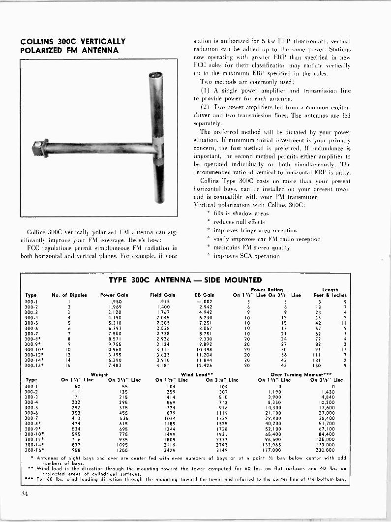
COLLINS 300C VERTICALLY POLARIZED FM ANTENNA
Collins 300C vertically polarized FM antenna can sig-
nificantly improve your FM coverage. Here's how: FCC regulations permit simultaneous FM radiation in
both horizontal and vertical planes. For example, if your
station is authorized for 5 kw ERP (horizontal), vertical radiation can be added up to the same power. Stations now operating with greater ERP than specified in new FCC rules for their classification may radiate vertically up to the maximum ERP specified in the rules.
Two methods are commonly used: (1) A single power amplifier and transmission line
to provide power for each antenna. (2) Two power amplifiers fed from a common exciter -
driver and two transmission lines. The antennas are fed separately.
The preferred method will be dictated by your power situation. If minimum initial investment is your primary concern, the first method is preferred. If redundance is important, the second method permits either amplifier to be operated individually or both simultaneously. The recommended ratio of vertical to horizontal ERP is unity.
Collins Type 300C costs no more than your present horizontal bays, can be installed on your present tower and is compatible with your FM transmitter. Vertical polarization with Collins 300C:
* fills in shadow areas * reduces null effects * improves fringe area reception * vastly improves car FM radio reception * maintains FM stereo quality * improves SCA operation
TYPE 300C ANTENNA - SIDE MOUNTED
Type No. of Dipoles Power Gain Field Gain DB Gain Power Rating
On 15/e" Line On 31/e" Line Length
Feet & Inches 300-I 1 .950 .975 -.002 3 3 3 9
300-2 2 1.969 1.400 2.942 6 6 13 7
300-3 3 3.120 1.767 4.942 9 9 23 4 300-4 4 4.198 2.045 6.230 10 12 33 2
300-5 5 5.310 2.305 7.251 10 15 42 11
300-6 6 6.393 2.528 8.057 10 18 57 9
300-7 7 7.500 2.738 8.751 10 21 62 7
300-8* 8 8.571 2.926 9.330 20 24 72 4 300-9* 9 9.755 3.124 9.892 20 27 82 2
300-10* 10 10.960 3.311 10.398 20 30 91 I I
300-12* 12 13.195 3.633 11.204 20 36 111 7 300-14* 14 15.290 3.910 11.844 20 42 131 2
300-16* 16 17.483 4.181 12.426 20 48 150 9
Type Weight
On 11/2" Line On 31/e" Line Wind Load**
On l'/e" Line On 31/a" Line Over Turning Moment***
On Is/8" Line On 31/e" Line 300-I 50 55 104 104 0 0 300-2 I I I 135 259 307 1,190 1,430 300-3 171 215 414 510 3,900 4,840 300-4 232 295 569 713 8,350 10,200 300-5 292 375 724 916 14,300 1 7,600 300-6 353 455 879 1119 21,100 27,000 300-7 413 535 1034 1322 29,900 38,400 300-8* 474 615 1189 1525 40,200 51,700 300-9* 534 695 1344 1728 52,100 67,100 300-10* 595 775 1499 1931 65,400 84,400 300-12* 716 935 1809 2337 96,600 125,000 300-14* 837 1095 2119 2743 133,965 173,000 300-I6* 958 1255 2429 3149 177,000 230,000
* Antennas of eight bays and over are center fed with even numbers of bays.
** Wind load in the direction through the mounting toward projected areas of cylindrical surfaces.
*** For 60 lbs. wind loading direction through the mounting
numbers of bays or at a point /: bay below center with odd
the tower computed for 60 lbs. on flat surfaces and 40 lbs. on
toward the tower and referred to the center line of the bottom bay.
31
TOWERS
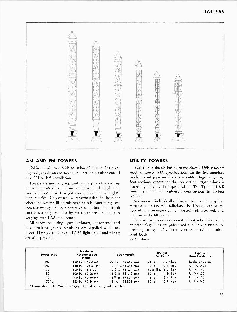
AM AND FM TOWERS
Collins furnishes a wide selection of both self-support- ing and guyed antenna towers to meet the requirements of
any AM or FM installation.
Towers are normally supplied with a protective coating of rust inhibitive paint prior to shipment, although they can be supplied with a galvanized finish at a slightly higher price. Galvanized is recommended in locations where the tower will be subjected to salt water spray, ex-
treme humidity or other corrosive conditions. The finish coat is normally supplied by the tower erector and is in keeping with FAA requirement.
All hardware, fittings, guy insulators, anchor steel and base insulator (where required) are supplied with each tower. The applicable FCC (FAA) lighting kit and wiring are also provided.
UTILITY TOWERS
Available in the six basic designs shown, Utility towers meet or exceed EIA specifications. In the five standard models, steel pipe members are welded together in 20 - foot sections, except for the top section length which is according to individual specification. The Type 170 KD tower is of bolted angle -iron construction in 10 -foot sections.
Anchors are individually designed to meet the require- ments of each tower installation. The I-beam used is im-
bedded in a concrete slab re-inforced with steel rods and with an earth fill on top.
Each section receives one coat of rust inhibitive, prim- er paint. Guy lines are galvanized and have a minimum breaking strength of at least twice the maximum calcu- lated loads. No Part Number
Tower Type Maximum
Recommended Height
Tower Width Weight Per Foot*
Type of Base Insulation
480 480 ft. (146.3 m) 33 in. ( 83.82 cm) 28 lbs. (12.7 kg Locke or Lappe 340 350 ft. (106.68 ml 19% in. ( 50.48 cm) 17 lbs. (7.71 kg) Utility 3401 220 250 ft. (76.2 m) 19176 in. (49.37 cm) 1 2'/2 lbs. (5.67 kg ) Utility 3401 180 200 ft. (60.96 in) 163;, in. (41.12 cm) 10 lbs. (4.54 kg) Utility 2201
120 200 ft. (60.96 m) 131/4 in. (33.34 cm) 8 lbs. (3.63 kg) Utility 2201 170KD 320 ft. (97.54 m) 18 in. ( 45.72 cm) 17 lbs. (7.71 kg) Utility 3401
'Tower steel only. Weight of guys, insulators, etc., not included.
i.5

FOOTAGE TABLE FOR BROADCAST TOWER HEIGHTS
KC
550
METERS
KC TO 1070
1 WAVE
KC
1/2 WAVE 1/4 WAVE KC
1080
METERS
KC TO 1600
1 -WAVE
KC
1/2 WAVE 1/4 WAVE
550 545 1787.6 893.8 446.8 1080 277.8 911.1 455.5 227.7 560 536 1758.0 879.0 439.5 1090 275.2 902.6 451.3 225.6 570 526 1725.3 862.6 431.3 580 5 1 7 1695.7 847.8 423.9 1100 272.7 894.4 447.2 223.6
590 509 1669.5 834.7 417.3 1110 270.3 886.5 443.2 221.6 1120 267.9 879.0 439.5 219.7
600 500 1640.0 820.0 410.0 1130 265.5 870.8 435.4 217.7
610 492 1612.7 806.3 403.1 1140 263.2 862.6 431.3 215.6
620 484 1587.5 799.7 396.8 1150 260.9 855.7 427.8 213.9
630 476 1561.2 780.6 390.3 1160 258.6 847.8 423.9 211.9
640 469 1546.3 773.1 386.5 1170 256.4 840.9 420.4 210.2
650 462 1515.3 757.6 378.8 1180 254.2 834.7 417.3 208.6
660 455 1492.4 746.2 373.1 1190 252.1 826.8 413.4 206.7
670 448 1469.4 734.7 367.3 680 441 1446.4 723.2 361.1 1200 250.0 820.0 410.0 205.0
690 435 1426.8 713.4 356.2 1210 247.9 813.1 406.5 203.2 1220 245.9 806.3 403.1 201.5
700 429 1407.1 703.5 351.2 1230 243.9 799.1 399.5 199.7
710 423 1387.4 693.7 346.8 1240 241.9 793.7 396.8 198.4
720 417 1367.7 683.8 341.9 1250 240.0 787.2 393.6 196.8
730 411 1348.0 674.0 337.0 1 260 238.1 780.9 390.4 195.2
740 405 1328.4 664.2 332.1 1270 236.2 774.7 387.3 193.6
750 400 1312.0 656.0 328.0 1280 234.4 768.8 384.4 192.2
760 395 1295.6 647.8 323.4 1290 232.6 762.9 381.4 190.7
770 390 1279.2 639.6 319.8 1300 230.8 757.0 378.5 189.2 780 385 1262.8 631.4 315.7
1 3 1 0 229.0 751.1 375.5 187.7 790 380 1246.4 623.2 311.6 1320 227.3 746.2 373.1 186.5
1330 225.6 739.9 369.9 184.9 800 375 1230.0 615.0 307.5 1340 223.9 734.7 "367.3 183.6 810 370 1213.6 606.8 303.4 1350 222.2 728.8 364.4 182.2 820 366 1200.4 600.2 300.1 1360 220.6 723 2 361.1 180.5 830 361 1184.0 592.0 296.0 1370 219.0 718.3 359.1 179.5 840 357 1170.9 585.4 292.7 1380 217.4 713.4 356.2 178.1 850 353 1157.8 578.9 289.4 1390 215.8 707.8 353.1 176.5 860 349 1144.7 572.3 286.1
870 345 1131.6 565.8 282.9 1400 214.3 703.5 351.2 175.6 880 341 1118.4 559.2 279.6 1410 212.8 696.9 348.4 174.2 890 337 1105.3 552.6 276.3 1420 211.3 693.7 346.8 173.4
1430 209.8 688.1 344.0 172.0 900 333 1092.2 546.1 273.0 1440 208.3 683.8 341.9 170.9 910 330 1082.4 541.2 270.6 1450 206.9 678.6 339.3 169.6 920 326 1069.2 534.6 267.3 1460 205.5 674.0 337.0 168.5 930 323 1059.4 529.7 264.8 1470 204.1 669.4 334.7 167.3 940 319 1046.3 523.1 261.5 1480 202.7 664.2 332.1 166.5 950 316 1036.4 518.2 259.1 1490 201.3 660.2 330.1 165.0 960 313 1026.6 513.3 256.6 970 309 1013.5 506.7 253.3 1500 200.0 656.0 328.0 164.0 980 306 1003.6 501.8 250.9 1510 198.7 651.7 325.8 162.9 990 303 993.8 496.9 248.4 1520 197.4 647.8 323.4 161.7
1 530 196.1 643.2 321.6 160.8 1000 300 984.0 492.0 246.0 1540 194.8 639.6 319.8 159.9 1010 297 974.1 487.5 243.7 1550 193.5 634.6 317.3 158.6 1020 294.1 964.6 482.3 241.1
1 560 192.3 631.4 315.7 157.8 1030 291.3 955.3 477.6 238.8
1 570 191.1 626.8 313.4 156.7 1040 288.5 946.2 473.1 236.5
1 580 189.9 623.2 3 1 1.6 155.8 1050 285.7 937.1 468.5 234.2
1 590 188.7 618.9 309.4 154.7 1060 283.0 928.2 464.1 232.0 1070 280.4 919.7 459.8 229.9 1600 187.5 615.0 307.5 153.7
36
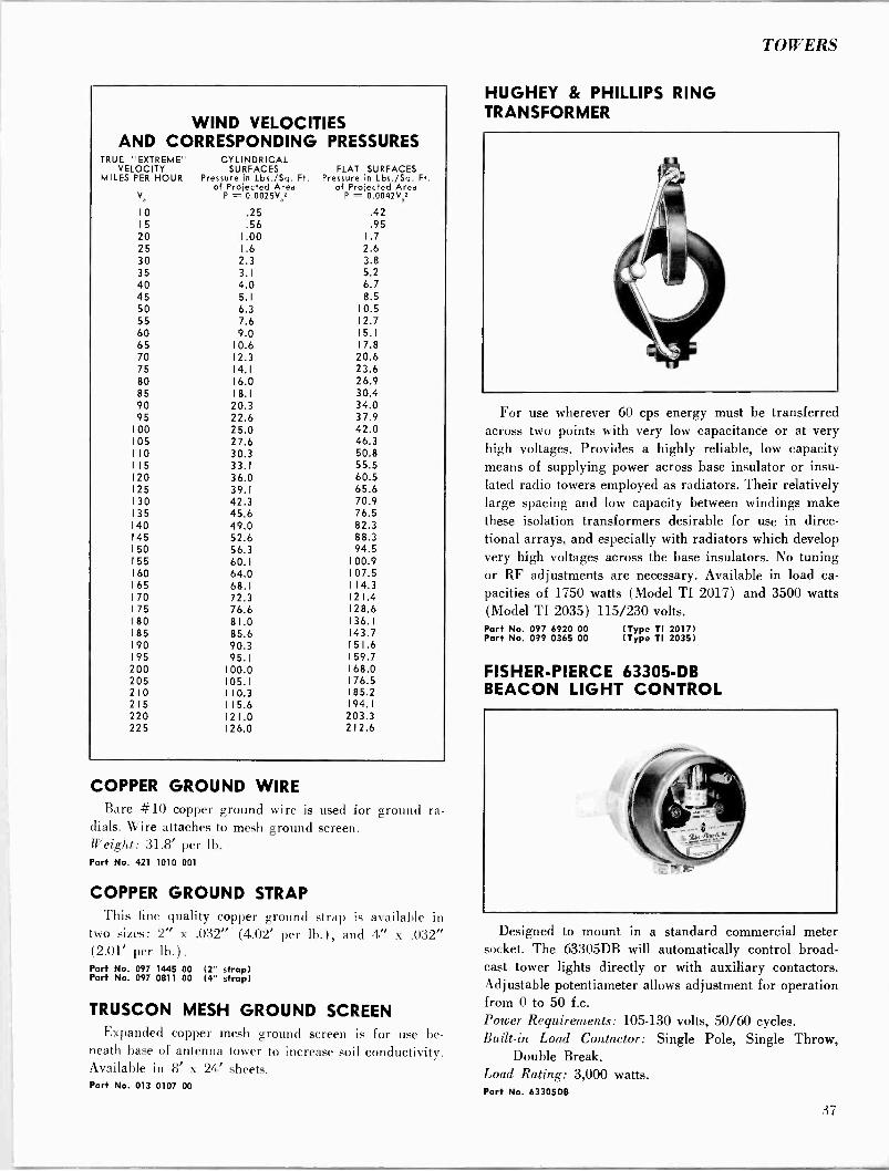
TOWERS
WIND VELOCITIES AND CORRESPONDING PRESSURES
TRUE "EXTREME" VELOCITY
MILES PER HOUR
V
CYLINDRICAL SURFACES
Pressure in Lbs./Sq. Ft. of Projected Area
P = 0.0025V2
FLAT SURFACES Pressure in Lbs./Sq. Ft.
of Projected Area P = 0.0042V.2
10 .25 .42 15 .56 .95 20 1.00 1.7 25 1.6 2.6 30 2.3 3.8 35 3.1 5.2 40 4.0 6.7 45 5.1 8.5 50 6.3 10.5 55 7.6 12.7 60 9.0 15.1 65 10.6 17.8 70 12.3 20.6 75 14.1 23.6 80 16.0 26.9 85 18.1 30.4 90 20.3 34.0 95 22.6 37.9
100 25.0 42.0 105 27.6 46.3 110 30.3 50.8 115 33.1 55.5 120 36.0 60.5 125 39.1 65.6 130 42.3 70.9 135 45.6 76.5 140 49.0 82.3 145 52.6 88.3 150 56.3 94.5 155 60.1 100.9 160 64.0 107.5 165 68.1 114.3 170 72.3 121.4 175 76.6 128.6 180 81.0 136.1 185 85.6 143.7 190 90.3 151.6 195 95.1 159.7 200 100.0 168.0 205 105.1 176.5 210 110.3 185.2 215 115.6 194.1 220 121.0 203.3 225 126.0 212.6
COPPER GROUND WIRE Bare #10 copper ground wire is used fur ground ra-
dials. Wire attaches to mesh ground screen. Weight: 31.8' per 1h.
Part No. 421 1010 001
COPPER GROUND STRAP This fine quality copper ground strap is available in
two sizes: 2" x .032" (4.02' per lb.). and 4" x .032" (2.01' per lb.). Part No. 097 1445 00 (2" strap) Part No. 097 0811 00 (4" strap)
TRUSCON MESH GROUND SCREEN Expanded copper mesh ground screen is for use be-
neath base of antenna tower to increase soil conductivity. Available in 8' x 24' sheets. Part No. 013 0107 00
HUGHEY & PHILLIPS RING TRANSFORMER
For use wherever 60 cps energy must be transferred across two points with very low capacitance or at very high voltages. Provides a highly reliable, low capacity means of supplying power across base insulator or insu- lated radio towers employed as radiators. Their relatively large spacing and low capacity between windings make these isolation transformers desirable for use in direc- tional arrays, and especially with radiators which develop very high voltages across the base insulators. No tuning or RF adjustments are necessary. Available in load ca- pacities of 1750 watts (Model TI 2017) and 3500 watts (Model TI 2035) 115/230 volts. Part No. 097 6920 00 (Type TI 2017) Part No. 099 0365 00 (Type TI 2035)
FISHER -PIERCE 63305 -DB BEACON LIGHT CONTROL
Designed to mount in a standard commercial meter socket. The 63305DB will automatically control broad- cast tower lights directly or with auxiliary contactors. Adjustable potentiameter allows adjustment for operation from 0 to 50 f.c. Power Requirements: 105-130 volts, 50/60 cycles. Built-in Load Contactor: Single Pole, Single Throw,
Double Break. Load Rating: 3,000 watts. Part No. 63305DB
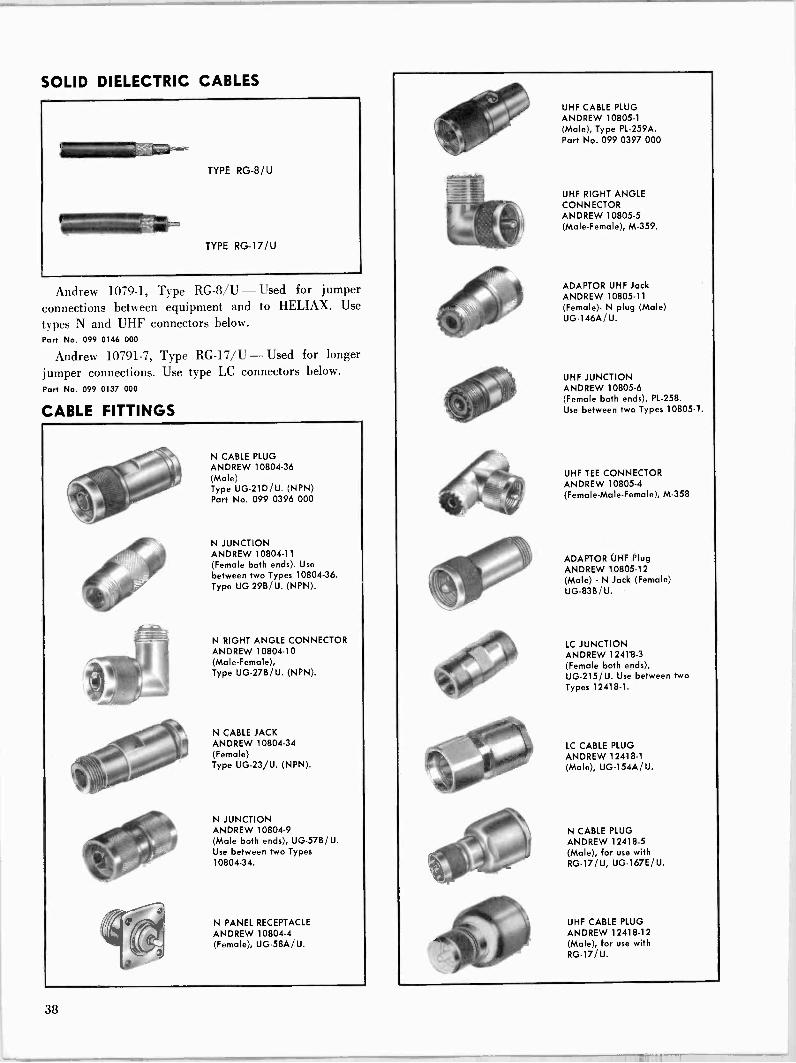
SOLID DIELECTRIC CABLES
Andrew 1079-1. Type RG -8/U - Used for jumper connections between equipment and to HELIAX. Use
types N and UHF connectors below. Part No. 099 0146 000
Andrew 10791-7, Type RG -17/U - Used for longer
jumper connections. Use type LC connectors below. Part No. 099 0137 000
CABLE FITTINGS
N CABLE PLUG ANDREW 10804-36 (Male) Type UG-21D/U. (NPN) Part No. 099 0396 000
N JUNCTION ANDREW 10804-11 (Female both ends). Use
between two Types 10804-36. Type UG-29B/U. (NPN).
N RIGHT ANGLE CONNECTOR ANDREW 10804-10 (Male -Female), Type UG-27B/U. (NPN).
N CABLE JACK ANDREW 10804-34 (Female) Type UG-23/U. (NPN).
N JUNCTION ANDREW 10804-9 (Male both ends), UG-57B/U. Use between two Types 10804-34.
N PANEL RECEPTACLE ANDREW 10804-4 (Female), UG-58A/U.
UHF CABLE PLUG ANDREW 10805-1 (Male), Type PL -259A. Part No. 099 0397 000
UHF RIGHT ANGLE CONNECTOR ANDREW 10805-5 (Male -Female), M-359.
ADAPTOR UHF Jack ANDREW 10805-11 (Female)- N plug (Male) UG-146A / U.
UHF JUNCTION ANDREW 10805-6 (Female both ends), PL -258. Use between two Types 10805-1.
UHF TEE CONNECTOR ANDREW 10805-4 (Female -Male -Female), M-358
ADAPTOR UHF Plug ANDREW 10805-12 (Male) - N Jack (Female) UG-83B/U.
LC JUNCTION ANDREW 12418-3 (Female both ends), UG-215/U. Use between two Types 12418-1.
LC CABLE PLUG ANDREW 12418-1 (Male), UG-154A/U.
N CABLE PLUG ANDREW 12418-5 (Male), for use with RG -17/U, UG-167E/U.
UHF CABLE PLUG
ANDREW 12418-12 (Male), for use with RG -17 / U.
38
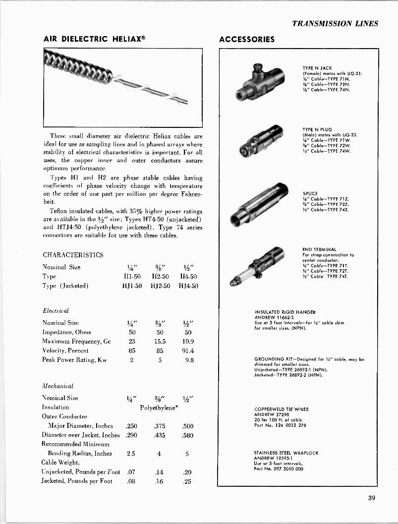
TRANSMISSION LINES
AIR DIELECTRIC HELIAXR
These small diameter air dielectric Heliax cables are ideal for use as sampling lines and in phased arrays where stability of electrical characteristics is important. For all uses, the copper inner and outer conductors assure optimum performance.
Types Hl and H2 are phase stable cables having coefficients of phase velocity change with temperature on the order of one part per million per degree Fahren- heit.
Teflon insulated cables, with 35% higher power ratings are available in the 1/2" size; Types HT4-50 (unjacketed) and HTJ4-50 (polyethylene jacketed). Type 74 series connectors are suitable for use with these cables.
CHARACTERISTICS
Nominal Size
Type
Type (Jacketed)
Electrical
1/4"
H1-50
HJ1-50
%" H2-50
HJ2-50
1/2i
H4-50
HJ4-50
Nominal Size 1/4rr 3/8,, 1/2"
Impedance, Ohms 50 50 50 Maximum Frequency, Gc 23 15.5 10.9
Velocity, Percent 85 85 91.4 Peak Power Rating, Kw 2 5 9.8
Mechanical
Nominal Size 1/4" 3/8" 1/2i
Insulation Polyethylene* Outer Conductor
Major Diameter, Inches .250 .375 .500 Diameter over Jacket, Inches .290 .435 .580 Recommended Minimum
Bending Radius, Inches 2.5 4 5
Cable Weight,
Unjacketed, Pounds per Foot .07 .14 .20 Jacketed, Pounds per Foot .08 .16 .25
ACCESSORIES
TYPE N JACK (Female) mates with UG-21. 'á" Cable-TYPE 71N. 3i" Cable-TYPE 72N. 1,72" Cable-TYPE 74N.
TYPE N PLUG (Male) mates with UG-23. Y4" Cable-TYPE 71W. %" Cable-TYPE 72W. t/" Cable-TYPE 74W.
SPLICE 14" Cable-TYPE 71Z. %" Cable-TYPE 72Z. '/2" Cable-TYPE 74Z.
END TERMINAL For strap connnection to center conductor. 14" Cable-TYPE 71T. 2/e" Cable-TYPE 72T. Y2" Cable-TYPE 74T.
INSULATED RIGID HANGER ANDREW 11662-3 Use at 5 foot intervals-for 1/2" cable shim for smaller sizes. (NPN).
GROUNDING KIT-Designed for Y's" cable, may be shimmed for smaller sizes. Unjacketed-TYPE 26892-1 (NPN). Jacketed-TYPE 26892-2 (NPN).
COPPERWELD TIE WIRES ANDREW 27290 20 for 100 ft. of cable. Part No. 124 0032 278
STAINLESS STEEL WRAPLOCK ANDREW 12395-1 Use at 5 foot intervals. Part No. 097 5010 000
39
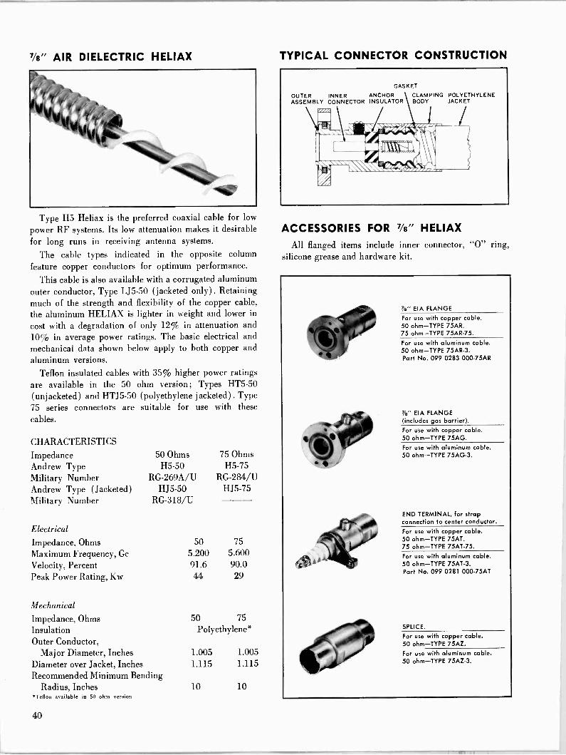
Vs" AIR DIELECTRIC HELIAX
Type H5 Heliax is the preferred coaxial cable for low
power RF systems. Its low attenuation makes it desirable for long runs in receiving antenna systems.
The cable types indicated in the opposite column feature copper conductors for optimum performance.
This cable is also available with a corrugated aluminum outer conductor, Type LJ5-50 (jacketed only). Retaining much of the strength and flexibility of the copper cable, the aluminum HELIAX is lighter in weight and lower in
cost with a degradation of only 12% in attenuation and 10% in average power ratings. The basic electrical and mechanical data shown below apply to both copper and aluminum versions.
Teflon insulated cables with 35% higher power ratings are available in the 50 ohm version; Types HT5-50 (unjacketed) and HTJ5-50 (polyethylene jacketed). Type 75 series connectors are suitable for use with these
cables.
CHARACTERISTICS Impedance 50 Ohms 75 Ohms Andrew Type H5-50 H5-75 Military Number RG-269A/U RG -284/U Andrew Type (Jacketed) HJ5-50 HJ5-75 Military Number RG -318/U
Electrical
Impedance, Ohms Maximum Frequency, Gc
Velocity, Percent Peak Power Rating, Kw
Mechanical
Impedance, Ohms Insulation Outer Conductor,
Major Diameter, Inches Diameter over Jacket, Inches Recommended Minimum Bending
Radius, Inches *Teflon available in 50 ohm version
50 75 5.200 5.600 91.6 90.0 44 29
50 75 Polyethylene*
1.005 1.005 1.115 1.115
10 10
TYPICAL CONNECTOR CONSTRUCTION
OUTER ASSEMBLY
GASKET
ANCHOR CLAMPING POLYETHYLENE INSULATOR BODY JACKET
me 11'4
' 1 I c I/rl I
I ,
INNER CONNECTOR
ACCESSORIES FOR '/s" HELIAX
All flanged items include inner connector, "0" ring, silicone grease and hardware kit.
7/a" EIA FLANGE
For use with copper cable. 50 ohm-TYPE 75AR. 75 ohm-TYPE 75AR-75.
For use with aluminum cable. 50 ohm-TYPE 75AR-3. Part No. 099 0283 000-75AR
?a" EIA FLANGE (includes gas barrier). For use with copper cable. 50 ohm-TYPE 75AG. For use with aluminum cable. 50 ohm-TYPE 75AG-3.
END TERMINAL, for strap connection to center conductor.
For use with copper cable. 50 ohm-TYPE 75AT. 75 ohm-TYPE 75AT-75.
For use with aluminum cable. 50 ohm-TYPE 75AT-3. Part No. 099 0281 000-75AT
SPLICE.
For use with copper cable. 50 ohm-TYPE 75AZ.
For use with aluminum cable. 50 ohm-TYPE 75AZ-3.
40
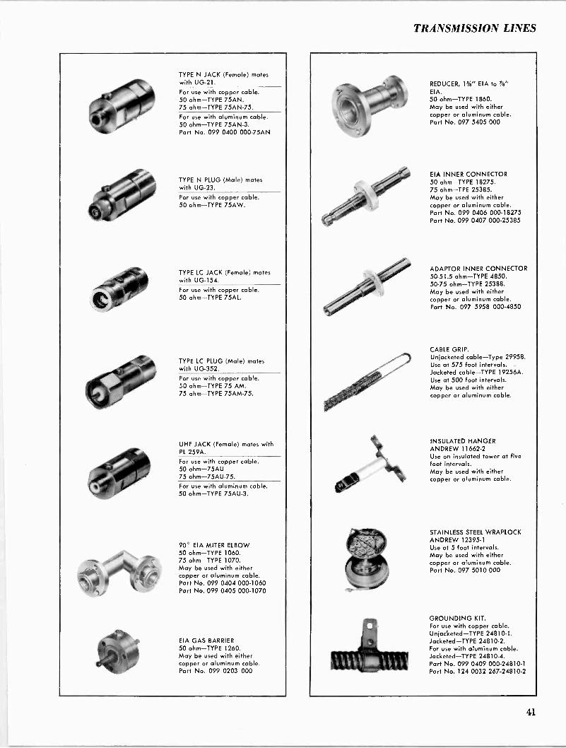
TRANSMISSION LINES
TYPE N JACK (Female) mates with UG-21.
For use with copper cable. 50 ohm-TYPE 75AN. 75 ohm-TYPE 75AN-75. For use with aluminum cable. 50 ohm-TYPE 75AN-3. Part No. 099 0400 000-75AN
TYPE N PLUG (Male) mates with UG-23.
For use with copper cable. 50 ohm-TYPE 75AW.
TYPE LC JACK (Female) mates with UG-154.
For use with copper cable. 50 ohm-TYPE 75AL.
TYPE LC PLUG (Male) mates with UG-352.
For use with copper cable. 50 ohm-TYPE 75 AM. 75 ohm-TYPE 75AM-75.
UHF JACK (Female) mates with PL 259A. For use with copper cable. 50 ohm-75AU 75 ohm-75AU-75. For use with aluminum cable. 50 ohm-TYPE 75AU-3.
90° EIA MITER ELBOW 50 ohm-TYPE 1060. 75 ohm-TYPE 1070. May be used with either copper or aluminum cable. Part No. 099 0404 000-1060 Part No. 099 0405 000-1070
EIA GAS BARRIER 50 ohm-TYPE 1260. May be used with either copper or aluminum cable. Part No. 099 0203 000
REDUCER, 1%" EIA to 7/e"
EIA. 50 ohm-TYPE 1860. May be used with either copper or aluminum cable. Part No. 097 5405 000
EIA INNER CONNECTOR 50 ohm-TYPE 18275. 75 ohm-TPE 25385. May be used with either copper or aluminum cable. Part No. 099 0406 000-18275 Part No. 099 0407 000-25385
ADAPTOR INNER CONNECTOR 50-51.5 ohm-TYPE 4850. 50-75 ohm-TYPE 25388. May be used with either copper or aluminum cable. Part No. 097 5958 000-4850
CABLE GRIP. Unjacketed cable-Type 29958. Use at 575 foot intervals. Jacketed cable-TYPE 19256A. Use at 500 foot intervals. May be used with either copper or aluminum cable.
INSULATED HANGER ANDREW 11662-2 Use on insulated tower at five foot intervals. May be used with either copper or aluminum cable.
STAINLESS STEEL WRAPLOCK ANDREW 12395-1 Use at 5 foot intervals. May be used with either copper or aluminum cable. Part No. 097 5010 000
GROUNDING KIT. For use with copper cable. Unjacketed-TYPE 24810-1. Jacketed-TYPE 24810-2. For use with aluminum cable. Jacketed-TYPE 24810-4. Part No. 099 0409 000-24810-1 Part No. 124 0032 267-24810-2
41

15/s" AIR DIELECTRIC HELIAX
Type H7 Heliax is widely used for medium power HF, AM and FM antenna installations. Its low attenuation also makes it popular at microwave frequencies.
Connectors include anchor insulator and feature posi- tive clamping of both conductors, eliminating any possi- bility of uncertain contact with movement, vibration or time. They are compensated electrically and are suitable for field attachment with ordinary hand tools.
The cable types indicated in the opposite column feature copper conductors for optimum performance.
This cable is also available with a corrugated aluminum outer conductor, Type LJ7-50 (jacketed only). Retaining much of the strength and flexibility of the copper cable, the aluminum Heliax is lighter in weight and lower in cost with a degradation of only 12% in attenuation and 10% in average power ratings. The basic electrical and mechanical data shown below apply to both copper and aluminum versions.
The connectors on the opposite page indicated for use with the aluminum cable are the same as those for copper cable, except plated.
CHARACTERISTICS
Impedance Andrew Type Military Number Andrew Type (Jacketed) Military Number
Electrical
Impedance, Ohms Maximum Frequency, Gc Velocity, Percent Peak Power Rating, Kw
Mechanical
50 Ohms 75 Ohms H7 -50A H7-75
RG-270B/U RG -286/U HJ7-50A HJ7-75
RG-319A/U RG -292/U
50 75 2.63 3.0 92.1 92.4 145 98
Impedance, Ohms 50 75
Insulation Polyethylene Outer Conductor,
Major Diameter, Inches Diameter over Jacket, Inches 2.00 2.00 Recommended Minimum Bending
Radius, Inches 20 20
1.830 1.830
TYPICAL CONNECTOR CONSTRUCTION
GASKET
OUTER NNER ANCHOR CLAMPING POLYETHYLENE ASSEMBLY CONDUCTOR INSULATOR BODY JACKET
ACCESSORIES FOR 15/8" HELIAX
All flanged items include inner connector, "0" ring, silicone grease and hardware kit.
14'%" EIA FLANGE
For use with copper cable. 50 ohm-TYPE 87R. 75 ohm-TYPE 77AR-75.
For use with aluminum cable. 50 ohm-TYPE 87R-3. Part No. 097 3002 000-87R
1%" EIA FLANGE (includes gas barrier). For use with copper cable. 50 ohm-TYPE 87G. For use with aluminum cable. 50 ohm-TYPE 87G-3. Part No. 124 0032 194-87G
REDUCER CONNECTOR (to 7/s" EIA flange).
For use with copper cable. 50 ohm-TYPE 87S. Part No. 099 3006 000
SPLICE.
For use with copper cable. 50 ohm-TYPE 87Z. 75 ohm-TYPE 77AZ-75.
For use with aluminum cable. 50 ohm-TYPE 87Z-3.
42
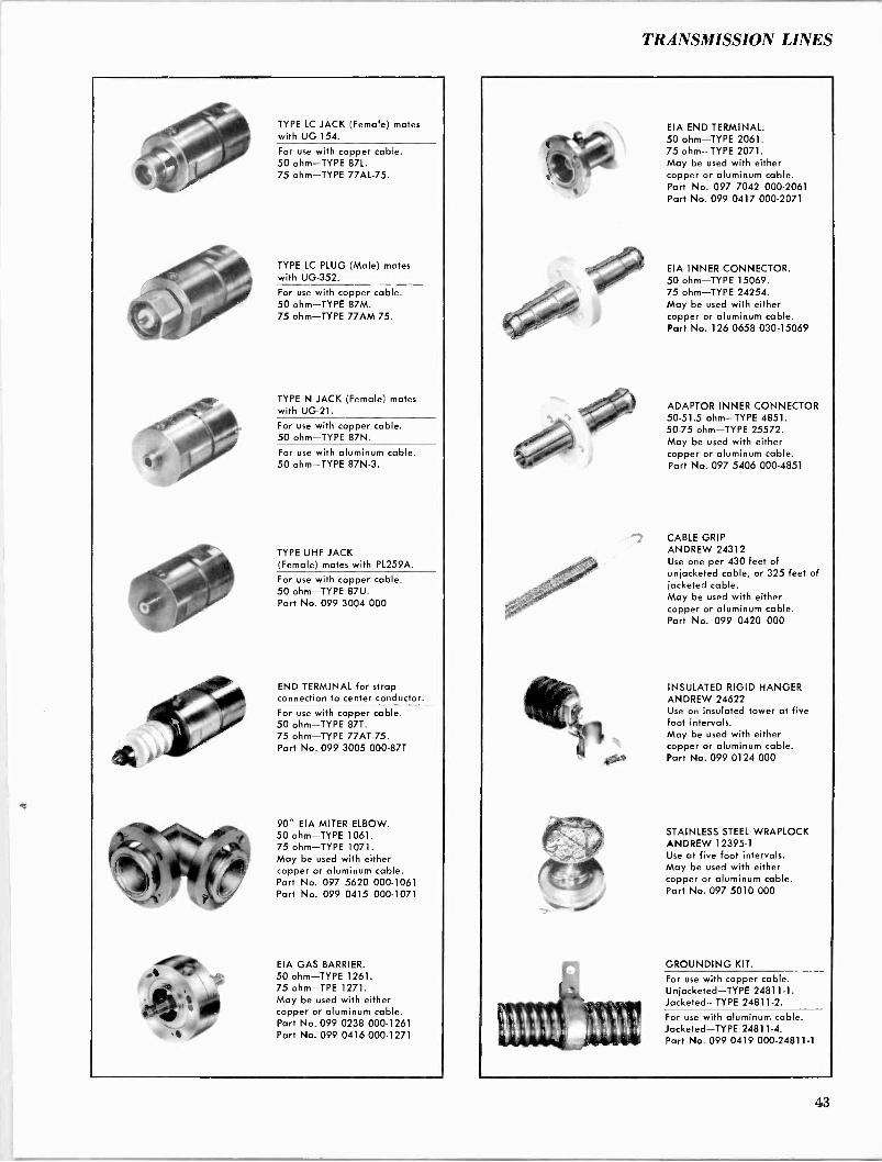
TRANSMISSION LINES
TYPE LC JACK (Female) mates with UG-154.
For use with copper cable. 50 ohm-TYPE 87L. 75 ohm-TYPE 77AL-75.
TYPE LC PLUG (Male) mates with UG-352.
For use with copper cable. 50 ohm-TYPE 87M. 75 ohm-TYPE 77AM-75.
TYPE N JACK (Female) mates with UG-21.
For use with copper cable. 50 ohm-TYPE 87N.
For use with aluminum cable. 50 ohm-TYPE 87N-3.
TYPE UHF JACK (Female) mates with PL259A.
For use with copper cable. 50 ohm-TYPE 87U. Part No. 099 3004 000
END TERMINAL for strap connection to center conductor.
For use with copper cable. 50 ohm-TYPE 87T. 75 ohm-TYPE 77AT-75. Part No. 099 3005 000-87T
90° EIA MITER ELBOW. 50 ohm-TYPE 1061. 75 ohm-TYPE 1071. May be used with either copper or aluminum cable. Part No. 097 5620 000-1061 Part No. 099 0415 000-1071
EIA GAS BARRIER. 50 ohm-TYPE 1261. 75 ohm-TPE 1271. May be used with either copper or aluminum cable. Part No. 099 0238 000-1261 Part No. 099 0416 000-1271
EIA END TERMINAL. 50 ohm-TYPE 2061. 75 ohm-TYPE 2071. May be used with either copper or aluminum cable. Part No. 097 7042 000-2061 Part No. 099 0417 000-2071
EIA INNER CONNECTOR. 50 ohm-TYPE 15069. 75 ohm-TYPE 24254. May be used with either copper or aluminum cable. Part No. 126 0658 030-15069
ADAPTOR INNER CONNECTOR 50-51.5 ohm-TYPE 4851. 50-75 ohm-TYPE 25572. May be used with either copper or aluminum cable. Part No. 097 5406 000-4851
CABLE GRIP ANDREW 24312 Use one per 430 feet of unjacketed cable, or 325 feet of jacketed cable. May be used with either copper or aluminum cable. Part No. 099 0420 000
INSULATED RIGID HANGER ANDREW 24622 Use on insulated tower at five foot intervals. May be used with either copper or aluminum cable. Part No. 099 0124 000
STAINLESS STEEL WRAPLOCK ANDREW 12395.1 Use at five foot intervals. May be used with either copper or aluminum cable. Part No. 097 5010 000
GROUNDING KIT.
For use with copper cable. Unjacketed-TYPE 24811-1. Jacketed-TYPE 24811-2.
For use with aluminum cable. Jacketed-TYPE 24811-4. Part No. 099 0419 000-24811-1
43
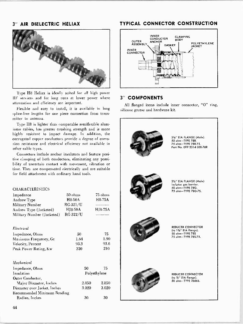
3" AIR DIELECTRIC HELIAX
Type H8 Heliax is ideally suited for all high power RF services and for long runs at lower power where attenuation and efficiency are important.
Flexible and easy to install, it is available in long splice -free lengths for one piece connection from trans- mitter to antenna.
Type H8 is lighter than comparable semiflexible alum- inum cables, has greater crushing strength and is more highly resistant to impact damage. In addition, the corrugated copper conductors provide a degree of corro- sion resistance and electrical efficiency not available in other cable types.
Connectors include anchor insulators and feature posi- tive clamping of both conductors, eliminating any possi- bility of uncertain contact with movement, vibration or time. They are compensated electrically and are suitable for field attachment with ordinary hand tools.
CHARACTERISTICS
Impedance 50 ohms 75 ohms Andrew Type H8 -50A H8 -75A Military Number RG -321/U --- Andrew Type (Jacketed) HJ8-50A HJ8-75A Military Number (Jacketed) RG -322/U
Electrical
Impedance, Ohms 50 75 Maximum Frequency, Gc 1.64 1.90 Velocity, Percent 93.3 93.6 Peak Power Rating, Kw 320 210
Mechanical Impedance, Ohms 50 75 Insulation Polyethylene Outer Conductor,
Major Diameter, Inches 2.850 2.850 Diameter over Jacket, Inches 3.020 3.020 Recommended Minimum Bending
Radius, Inches 30 30
TYPICAL CONNECTOR CONSTRUCTION
OUTER ASSEMBLY
INNER CONNECTOR
INNER CONDUCTOR ANCHOR
CLAMPING BODY
GASKET .. pSe
1%11111111111Ì
lOurin!_._............
POLYETHYLENE JACKET
3" COMPONENTS All flanged items include inner connector, "0" ring,
silicone grease and hardware kit.
3'é" EIA FLANGE (Male). 50 ohm-TYPE 78R. 75 ohm-TYPE 78R-75. Part No. 099 2314 000-78R
3''8" EIA FLANGE (Male) includes gas barrier. 50 ohm-TYPE 78G. 75 ohm-TYPE 78G-75.
REDUCER CONNECTOR (to i'h" EIA flange). 50 ohm-TYPE 78S 75 ohm-TYPE 78S-75.
REDUCER CONNECTOR (to G" EIA flange). 50 ohm-TYPE 26666.
44
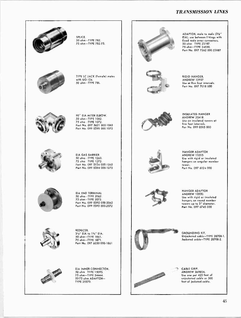
TRANSMISSION LINES
SPLICE. 50 ohm-TYPE 78Z. 75 ohm-TYPE 78Z-75.
TYPE LC JACK (Female) mates with UG-154. 50 ohm-TYPE 78L.
90° EIA MITER ELBOW. 50 ohm-TYPE 1062. 75 ohm-TYPE 1072. Part No. 097 5621 000-1062 Part No. 099 0391 000-1072
EIA GAS BARRIER 50 ohm-TYPE 1262. 75 ohm-TYPE 1272. Part No. 097 5754 000-1262 Part No. 099 0394 000-1272
EIA END TERMINAL 50 ohm-TYPE 2062. 75 ohm-TYPE 2072. Part No. 099 0392 000-2062 Part No. 099 0393 000-2072
REDUCER. 31/8" EIA to 15/s" EIA. 50 ohm-TYPE 1861. 75 ohm-TYPE 1871. Part No. 097 6050 000-1861
EIA INNER CONNECTOR. 50 ohm-TYPE 15093. 75 ohm-TYPE 24444. 50-75 ohm ADAPTOR- TYPE 25570.
ADAPTOR, male to male (31/8" EIA), use between fittings with fixed male inner connectors. 50 ohm-TYPE 23187. 75 ohm-TYPE 24530. Part No. 097 7262 000-23187
RIGID HANGER. ANDREW 13927 Use at five foot intervals. Part No. 097 7018 000
INSULATED HANGER ANDREW 22418. Use on insulated towers at five foot intervals. Par No. 099 0515 000
HANGER ADAPTOR ANDREW 13555. Use with rigid or insulated hangers on angular member tower. Part No. 097 6124 000
HANGER ADAPTOR ANDREW 13550. Use with rigid or insulated hangers on round member towers up to 3" diameter. Part No. 097 6745 000
GROUNDING KIT. Unjacketed cable-TYPE 28708-1. Jacketed cable-TYPE 28708-2.
CABLE GRIP. ANDREW 26985A. Use one per 425 feet of unjacketed cable or 300 feet of jacketed cable.
45
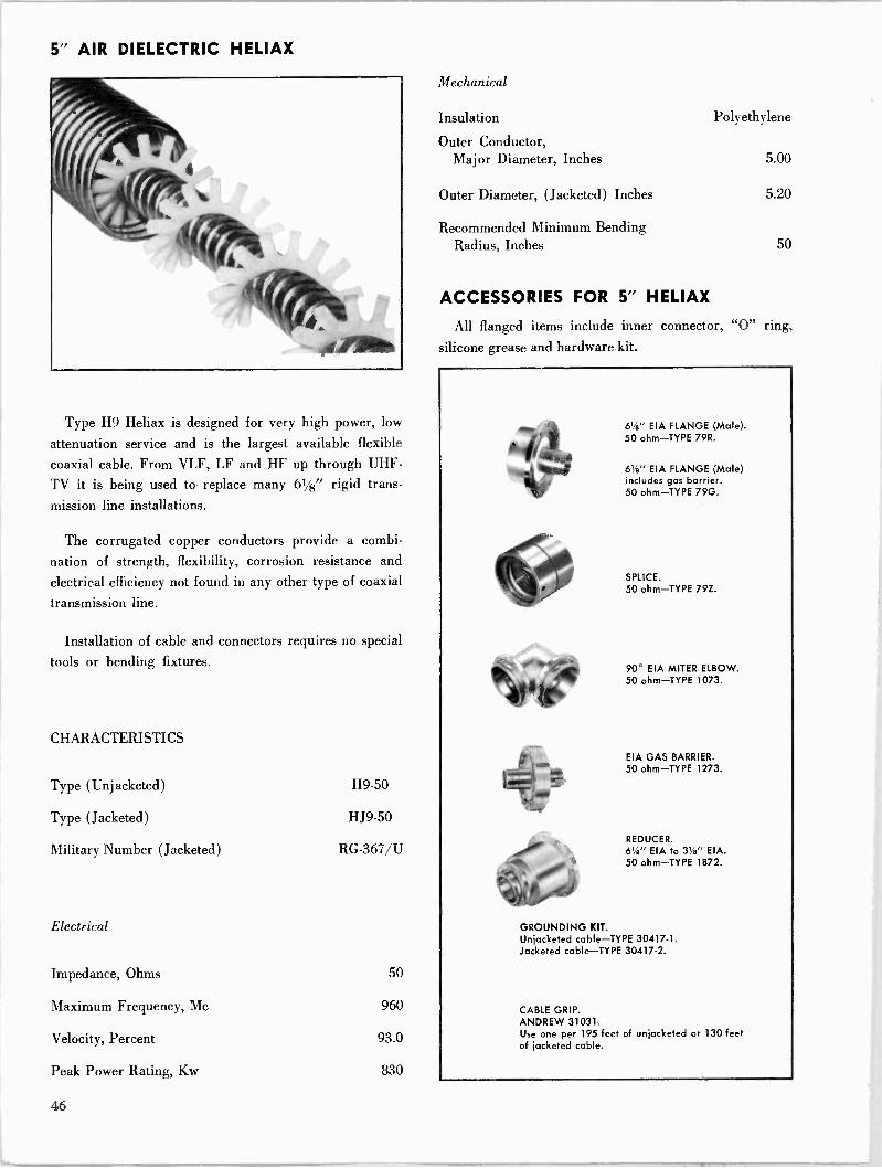
5" AIR DIELECTRIC HELIAX
Type H9 Heliax is designed for very high power, low
attenuation service and is the largest available flexible
coaxial cable. From VLF, LF and HF up through UHF -
TV it is being used to replace many 61/8" rigid trans-
mission line installations.
The corrugated copper conductors provide a combi-
nation of strength, flexibility, corrosion resistance and
electrical efficiency not found in any other type of coaxial
transmission line.
Installation of cable and connectors requires no special
tools or bending fixtures.
CHARACTERISTICS
Type (Unjacketed) H9-50
Type (Jacketed) HJ9-50
Military Number (Jacketed) RG -367/U
Electrical
Impedance, Ohms 50
Maximum Frequency, Mc 960
Velocity, Percent 93.0
Peak Power Rating, Kw 830
Mechanical
Insulation
Outer Conductor, Major Diameter, Inches
Outer Diameter, (Jacketed) Inches
Recommended Minimum Bending Radius, Inches
Polyethylene
5.00
5.20
50
ACCESSORIES FOR 5" HELIAX
All flanged items include inner connector, "0" ring,
silicone grease and hardware kit.
61/8" EIA FLANGE (Male). 50 ohm-TYPE 79R.
61/8" EIA FLANGE (Male) includes gas barrier. 50 ohm-TYPE 79G.
SPLICE. 50 ohm-TYPE 79Z.
90° EIA MITER ELBOW. 50 ohm-TYPE 1073.
EIA GAS BARRIER. 50 ohm-TYPE 1273.
REDUCER. 61" EIA to 3'/e" EIA. 50 ohm-TYPE 1872.
GROUNDING KIT. Unjacketed cable-TYPE 30417-1. Jacketed cable-TYPE 30417-2.
CABLE GRIP. ANDREW 31031. Use one per 195 feet of unjacketed or 130 feet of jacketed cable.
46
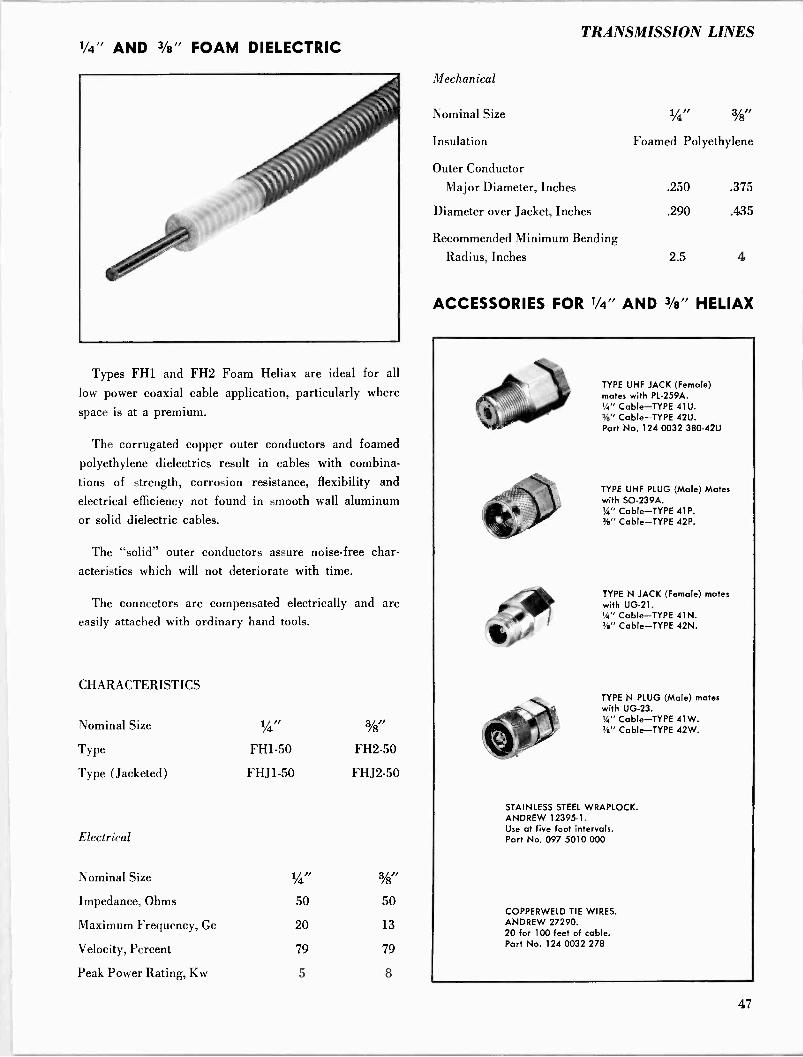
'/4" AND 3/8" FOAM DIELECTRIC TRANSMISSION LINES
Types FH1 and FH2 Foam Heliax are ideal for all
low power coaxial cable application, particularly where
space is at a premium.
The corrugated copper outer conductors and foamed
polyethylene dielectrics result in cables with combina-
tions of strength, corrosion resistance, flexibility and
electrical efficiency not found in smooth wall aluminum
or solid dielectric cables.
The "solid" outer conductors assure noise -free char-
acteristics which will not deteriorate with time.
The connectors are compensated electrically and are
easily attached with ordinary hand tools.
CHARACTERISTICS
Nominal Size 1/4" 3/8',
Type FH1-50 FH2-50
Type (Jacketed) FHJ1-50 FHJ2-50
Electrical
Nominal Size 14" 3/g"
Impedance, Ohms 50 50
Maximum Frequency, Ge 20 13
Velocity, Percent 79 79
Peak Power Rating, Kw 5 8
Mechanical
Nominal Size
Insulation
1/4/ 3/8 ,
Foamed Polyethylene
Outer Conductor
Major Diameter, Inches .250 .375
Diameter over Jacket, Inches .290 .435
Recommended Minimum Bending
Radius, Inches 2.5 4
ACCESSORIES FOR 1/4" AND 3/8" HELIAX
TYPE UHF JACK (Female) mates with PL -259A. 14" Cable-TYPE 41U. Ye' Cable-TYPE 42U. Part No. 124 0032 380-42U
TYPE UHF PLUG (Male) Mates with SO -239A. 14" Cable-TYPE 41P. %" Cable-TYPE 42P.
TYPE N JACK (Female) mates with UG-21. 1/4" Cable-TYPE 41N. W' Cable-TYPE 42N.
TYPE N PLUG (Male) mates with UG-23. 1/4" Cable-TYPE 41W. '/e" Cable-TYPE 42W.
STAINLESS STEEL WRAPLOCK. ANDREW 12395-1. Use at five foot intervals. Part No. 097 5010 000
COPPERWELD TIE WIRES. ANDREW 27290. 20 for 100 feet of cable. Part No. 124 0032 278
47

1/2" FOAM DIELECTRIC HELIAX
Type FH4 Foam Heliax is designed for fixed station antenna use and other low power applications.
The corrugated outer conductor and foam dielectric provide a combination of strength, flexibility, efficiency
and permanence not available in semiflexible smooth wall
or solid dielectric cables.
The cable types listed in the opposite column feature copper conductors for optimum performance.
This cable is also available with a corrugated aluminum outer conductor, Type FLJ4-50 (jacketed only). Retain- ing much of the strength and flexibility of the copper cable, the aluminum Heliax is lighter in weight and lower in cost with a degradation of only 12% in attenuation and 10% in average power ratings. The basic electrical and mechanical data shown below apply to both copper and aluminum versions.
The connectors on the opposite page indicated for use
with the aluminum cable are the same as those for copper cable, except plated.
CHARACTERISTICS
Impedance Type Type (Jacketed) Military Number (Jacketed)
Electrical
Impedance, Ohms Maximum Frequency, Gc Velocity, Percent Peak Power Rating, Kw
50 ohms FH4-50A FHJ4-50A RG -366/U
Mechanical
Impedance, Ohms Insulation Outer Conductor,
Major Diameter, Inches Diameter over Jacket, Inches Recommended Minimum Bending
Radius, Inches
50 8.1 79 19
75 ohms FH4-75
FHJ4-75
75 9.1 79
12.7
50 70 Foamed Polyethylene
.540 .540
.620 .101
5 5
TYPICAL CONNECTOR CONSTRUCTION
INNER TEFLON OUTER CLAMPING CONDUCTOR BEAD BODY BODY
ek \ 1>z, /e f, ,z i - r,L -1. : --,_-- \r"`\nu ,,, /AMA.. .
ACCESSORIES FOR 1/2" HELIAX
All flanged items include inner connector "O" ring, silicone grease and hardware kit.
7/e" EIA FLANGE, includes inner co,nector, "O" ring and hardware. For use with copper cable. 50 ohm-TYPE 44AR.
For use with aluminum cable. 50 ohm-TYPE 44AR-3.
SPLICE. For use with copper cable. 50 ohm-TYPE 44AZ. Part No. 124 0032
TYPE LC PLUG (Male) mates with UG-352. For use with copper cable. 50 ohm-TYPE 44AM.
TYPE LC JACK (Female) motes with UG-154. For use with copper cable. 50 ohm-TYPE 44AL.
48
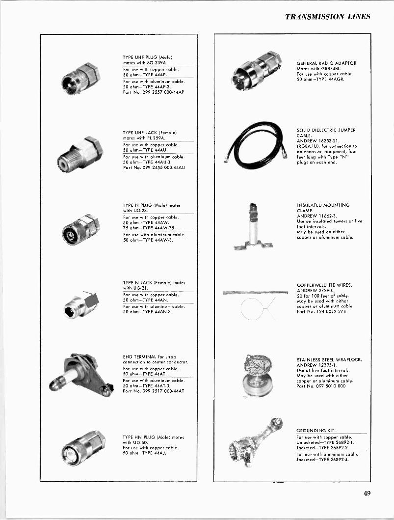
TRANSMISSION LINES
TYPE UHF PLUG (Male) mates with SO -239A.
For use with copper cable. 50 ohm-TYPE 44AP.
For use with aluminum cable. 50 ohm-TYPE 44AP-3. Part No. 099 2557 000-44AP
TYPE UHF JACK (Female) mates with PL -259A.
For use with copper cable. 50 ohm-TYPE 44AU.
For use with aluminum cable. 50 ohm-TYPE 44AU-3. Part No. 099 2455 000-44AU
TYPE N PLUG (Male) mates with UG-23.
For use with copper cable. 50 ohm-TYPE 44AW. 75 ohm-TYPE 44AW-75.
For use with aluminum cable. 50 ohm-TYPE 44AW-3.
TYPE N JACK (Female) mates with UG-21.
For use with copper cable. 50 ohm-TYPE 44AN. For use with aluminum cable. 50 ohm-TYPE 44AN-3.
END TERMINAL for strap connection to center conductor.
For use with copper cable. 50 ohm-TYPE 44AT.
For use with aluminum cable. 50 ohm-TYPE 44AT-3. Part No. 099 2517 000-44AT
TYPE HN PLUG (Male) mates with UG-60. For use with copper cable. 50 ohm-TYPE 44AJ.
-:----.-r
GENERAL RADIO ADAPTOR. Mates with GR874BL. For use with copper cable. 50 ohm-TYPE 44AGR.
SOLID DIELECTRIC JUMPER CABLE. ANDREW 16253-21. (RG8A/U), for connection to antennas or equipment, four feet long with Type "N" plugs on each end.
INSULATED MOUNTING CLAMP. ANDREW 11662-3. Use on insulated towers at five foot intervals. May be used on either copper or aluminum cable.
COPPERWELD TIE WIRES. ANDREW 27290. 20 for 100 feet of cable. May be used with either copper or aluminum cable. Part No. 124 0032 278
STAINLESS STEEL WRAPLOCK. ANDREW 12395-1. Use at five foot intervals. May be used with either copper or aluminum cable. Part No. 097 5010 000
GROUNDING KIT.
For use with copper cable. Unjacketed-TYPE 26892-1. Jacketed-TYPE 26892-2.
For use with aluminum cable. Jacketed-TYPE 26892-4.
49

7/8" FOAM DIELECTRIC HELIAX
Type FH5 Foam Heliax is used extensively for long run fixed station antenna installations and HF receiving systems.
This cable outperforms comparable semiflexible smooth
wall cables and all solid dielectric cables.
The cable types listed in the opposite column feature copper conductors for optimum performance.
This cable is also available with a corrugated aluminum outer conductor, Type FLJ5-50 (jacketed only). Retain- ing much of the strength and flexibility of the copper cable, the aluminum Heliax is lighter in weight and lower in cost with a degradation of only 12% in attenuation and 10% in average power ratings. The basic electrical and mechanical data shown below apply to both copper and aluminum versions.
The connectors on the opposite page indicated for use
with the aluminum cable are the same as those for copper cable, except plated.
CHARACTERISTICS
Impedance 50 ohms 75 ohms Andrew Type FH5-50 FH5-75 Military Number RG -324/U --- Andrew Type (Jacketed) FHJS-50 FHJ5-75 Military Number RG -323/U
Electrical
Impedance, Ohms 50 75 Maximum Frequency, Gc 4.4 4.9 Velocity, Percent 79 79
Peak Power Rating, Kw 44 29
Mechanical
Impedance, Ohms 50 75
Insulation Foamed Polyethylene Outer Conductor,
Major Diameter, Inch .980 .980
Outer Diameter, (Jacketed) , Inches 1.090 1.090
Recommended Minimum Bending Radius, Inches 10 10
TYPICAL CONNECTOR CONSTRUCTION
SWIVEL OUTER INNER CLAMPING FLANGE BODY CONDUCTOR BODY
- - #;.,.. sI111111Q11 il
.//,,,,,,,,///y , .. 7\
ACCESSORIES FOR /8" HELIAX
All flanged items include inner connector, "0" ring, silicone grease and hardware kit.
7/8" EIA FLANGE.
For use with copper cable. 50 ohm -TYPE 45AR.
For use with aluminum cable. 50 ohm-TYPE 45AR-3. Part No. 124 0032 419-45AR
SPLICE.
For use with copper cable. 50 ohm-TYPE 45AZ.
For use with aluminum cable. 50 ohm-TYPE 45AZ-3. Part No. 124 0032 152-45AZ
TYPE UHF JACK (Female) mates with PL -259A.
For use with copper cable. 50 ohm-TYPE 45AU.
For use with aluminum cable. 50 ohm-TYPE 45AU-3. Part No. 099 2553 000-45AU
TYPE UHF PLUG (Male) mates with SO -239A.
For use with copper cable. 50 ohm-TYPE 45AP.
For use with aluminum cable. 50 ohm-TYPE 45AP-3.
50
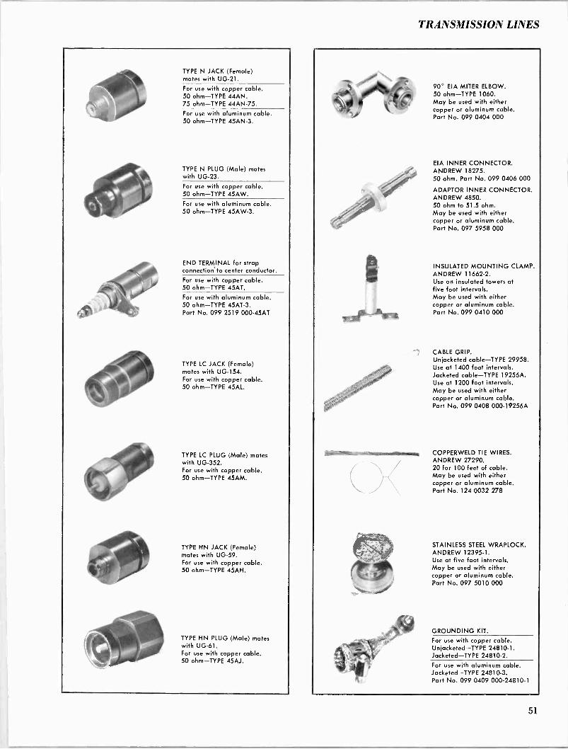
TRANSMISSION LINES
4b'
TYPE N JACK (Female) mates with UG-21.
For use with copper cable. 50 ohm-TYPE 44AN. 75 ohm-TYPE 44AN-75.
For use with aluminum cable. 50 ohm-TYPE 45AN-3.
TYPE N PLUG (Male) mates with UG-23.
For use with copper cable. 50 ohm-TYPE 45AW.
For use with aluminum cable. 50 ohm-TYPE 45AW-3.
END TERMINAL for strap connection to center conductor.
For use with copper cable. 50 ohm-TYPE 45AT.
For use with aluminum cable. 50 ohm-TYPE 45AT-3. Part No. 099 2519 000-45AT
TYPE LC JACK (Female) mates with UG-154. For use with copper cable. 50 ohm-TYPE 45AL.
TYPE LC PLUG (Male) mates with UG-352. For use with copper cable. 50 ohm-TYPE 45AM.
TYPE HN JACK (Female) mates with UG-59. For use with copper cable. 50 ohm-TYPE 45AN.
TYPE HN PLUG (Male) mates with UG-61. For use with copper cable. 50 ohm-TYPE 45AJ.
90° EIA MITER ELBOW. 50 ohm-TYPE 1060. May be used with either copper or aluminum cable. Part No. 099 0404 000
EIA INNER CONNECTOR. ANDREW 18275. 50 ohm. Part No. 099 0406 000
ADAPTOR INNER CONNECTOR. ANDREW 4850. 50 ohm to 51.5 ohm. May be used with either copper or aluminum cable. Part No. 097 5958 000
INSULATED MOUNTING CLAMP. ANDREW 11662-2. Use on insulated towers at five foot intervals. May be used with either copper or aluminum cable. Part No. 099 0410 000
CABLE GRIP. Unjacketed cable-TYPE 29958. Use at 1400 foot intervals. Jacketed cable-TYPE 19256A. Use at 1200 foot intervals. May be used with either copper or aluminum cable. Part No. 099 0408 000-19256A
COPPERWELD TIE WIRES. ANDREW 27290. 20 for 100 feet of cable. May be used with either copper or aluminum cable. Part No. 124 0032 278
STAINLESS STEEL WRAPLOCK. ANDREW 12395-1. Use at five foot intervals. May be used with either copper or aluminum cable. Part No. 097 5010 000
GROUNDING KIT.
For use with copper cable. Unjacketed-TYPE 24810-1. Jacketed-TYPE 24810-2. For use with aluminum cable. Jacketed-TYPE 24810-3. Part No. 099 0409 000-24810-1
51

13/4" FOAM DIELECTRIC HELIAX
Type FH7 Foam Heliax provides high efficiency and power handling capabilities without the need for pres- surization.
As with all Heliax sizes, connectors for FH7 are com-
pensated electrically and are suitable for either factory or field installation with ordinary hand tools.
The cable types listed in the opposite column feature copper conductors for optimum performance.
This cable is also available with a corrugated aluminum outer conductor, Type FLJ7-50 (jacketed only). Retain- ing much of the strength and flexibility of the copper cable, the aluminum Heliax is lighter in weight and lower in cost with a degradation of only 12% in attenuation and 10% in average power ratings. The basic electrical and mechanical data shown below apply to both copper and aluminum versions.
CHARACTERISTICS
Impedance 50 ohms
Type FH7-50
Type (Jacketed) FHJ7-50
Electrical
Impedance, Ohms 50
Maximum Frequency, Gc 2.3
Velocity, Percent 79
Peak Power Rating, Kw 145
Mechanical
Insulation Foamed Polyethylene
Outer Conductor, Major Diameter, Inches 1.830
Diameter over Jacket, Inches 2.000
Recommended Minimum Bending Radius, Inches 20
TYPICAL CONNECTOR CONSTRUCTION
OUTER INNER CLAMPING BODY CONDUCTOR BODY
ACCESSORIES FOR 15/8" HELIAX
All flanged items include inner connector, "O" ring, silicone grease and hardware kit.
1%" EIA FLANGE.
For use with copper cable. 50 ohm-TYPE 47R.
For use with aluminum cable. 50 ohm-TYPE 47R-3. Part No. 124 0032 150-47R
SPLICE.
For use with copper cable. 50 ohm-TYPE 47Z.
For use with aluminum cable. 50 ohm-TYPE 47Z-3.
TYPE LC JACK (Female) mates with UG-154.
For use with copper cable. 50 ohm-TYPE 47L.
For use with aluminum cable. 50 ohm-TYPE 47L-3.
TYPE N JACK (Female) mates with UG-21.
For use with copper cable. 50 ohm-TYPE 47N. For use with aluminum cable. 50 ohm-TYPE 47N-3.
52
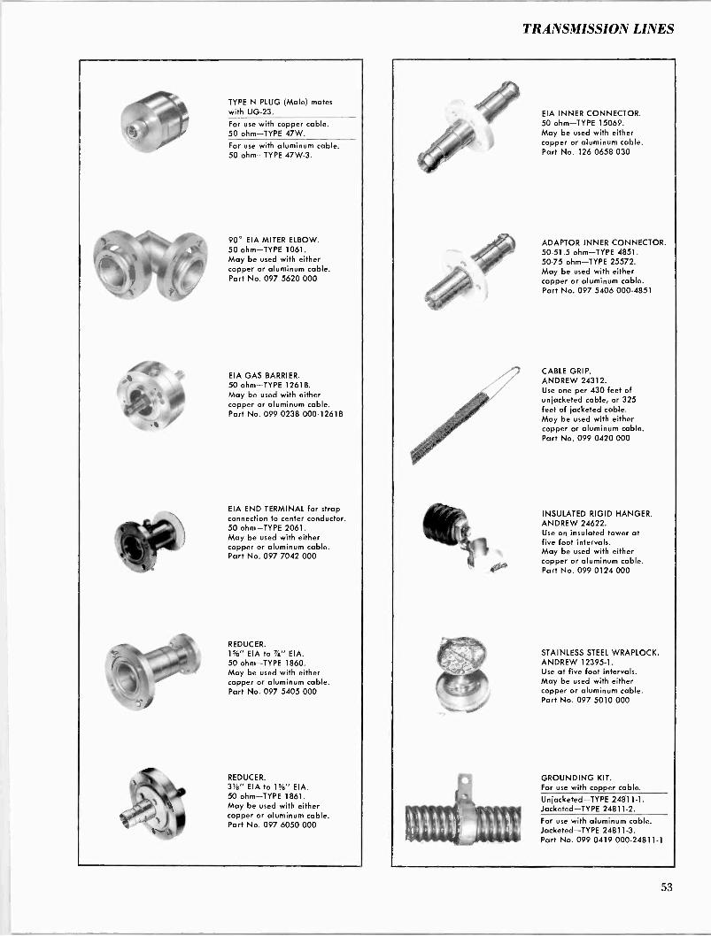
TRANSMISSION LINES
. ot
TYPE N PLUG (Male) mates with UG-23.
For use with copper cable. 50 ohm-TYPE 47W.
For use with aluminum cable. 50 ohm-TYPE 47W-3.
90° EIA MITER ELBOW. 50 ohm-TYPE 1061. May be used with either copper or aluminum cable. Part No. 097 5620 000
EIA GAS BARRIER. 50 ohm-TYPE 1261B. May be used with either copper or aluminum cable. Part No. 099 0238 000-1261B
EIA END TERMINAL for strap connection to center conductor. 50 ohm-TYPE 2061. May be used with either copper or aluminum cable. Part No. 097 7042 000
REDUCER. 1%" EIA to 7/e" EIA. 50 ohm-TYPE 1860. May be used with either copper or aluminum cable. Part No. 097 5405 000
REDUCER. 3/e" EIA to Hie" EIA. 50 ohm-TYPE 1861. May be used with either copper or aluminum cable. Part No. 097 6050 000
_
EIA INNER CONNECTOR. 50 ohm-TYPE 15069. May be used with either copper or aluminum cable. Part No. 126 0658 030
ADAPTOR INNER CONNECTOR. 50-51.5 ohm-TYPE 4851. 50-75 ohm-TYPE 25572. May be used with either copper or aluminum cable. Part No. 097 5406 000-4851
CABLE GRIP. ANDREW 24312. Use one per 430 feet of unjacketed cable, or 325 feet of jacketed cable. May be used with either copper or aluminum cable. Part No. 099 0420 000
INSULATED RIGID HANGER. ANDREW 24622. Use on insulated tower at five foot intervals. May be used with either copper or aluminum cable. Part No. 099 0124 000
STAINLESS STEEL WRAPLOCK. ANDREW 12395-1. Use at five foot intervals. May be used with either copper or aluminum cable. Part No. 097 5010 000
GROUNDING KIT. For use with copper cable.
Unjacketed-TYPE 24811-1. Jacketed-TYPE 24811-2.
For use with aluminum cable. Jacketed-TYPE 24811-3. Part No. 099 0419 000-24811-1
53
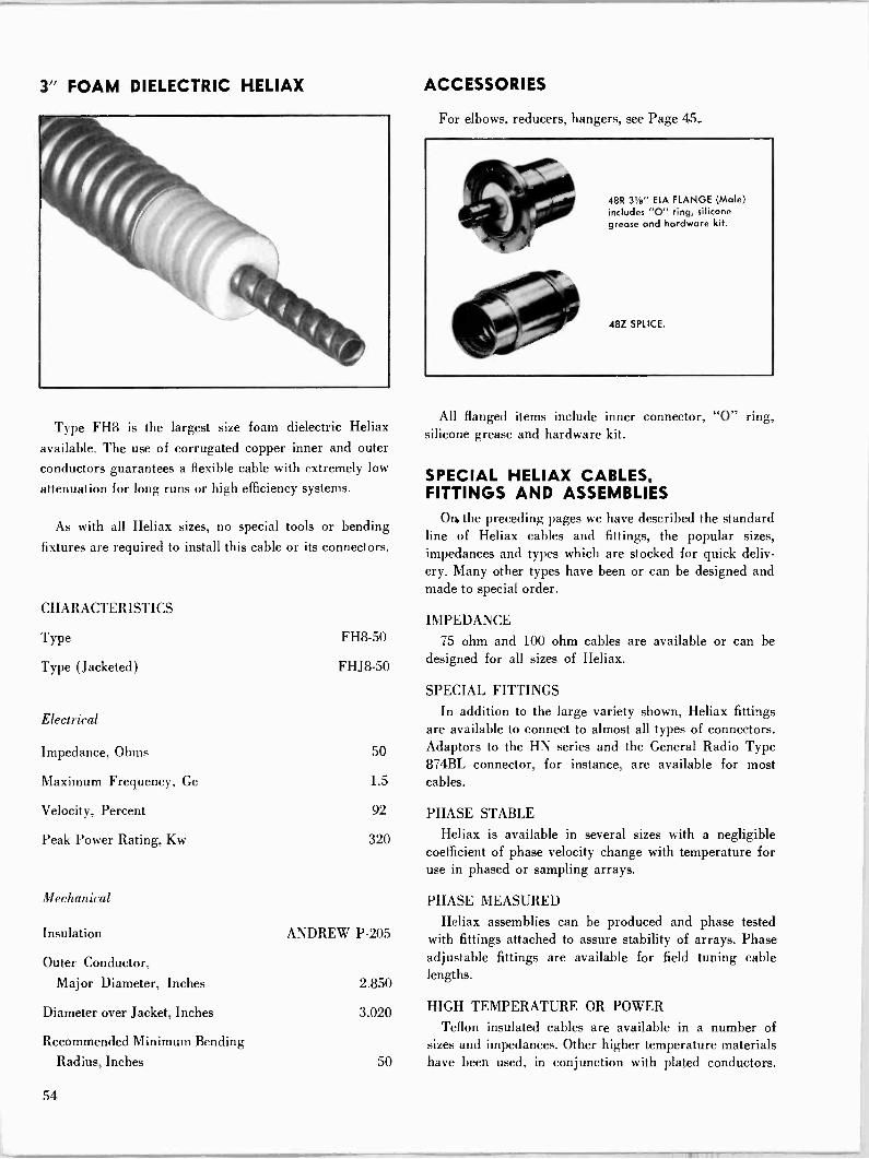
3" FOAM DIELECTRIC HELIAX
Type FH8 is the largest size foam dielectric Heliax
available. The use of corrugated copper inner and outer conductors guarantees a flexible cable with extremely low
attenuation for long runs or high efficiency systems.
As with all Heliax sizes, no special tools or bending
fixtures are required to install this cable or its connectors.
CHARACTERISTICS
Type
Type (Jacketed)
Electrical
Impedance, Ohms
Maximum Frequency, Ge
Velocity, Percent
Peak Power Rating, Kw
Mechanical
Insulation
Outer Conductor,
Major Diameter, Inches
Diameter over Jacket, Inches
Recommended Minimum Bending Radius, Inches
FH8-50
FHJ8-50
50
1.5
92
320
ANDREW P-205
2.850
3.020
ACCESSORIES
For elbows, reducers, hangers, see Page 45_
48R 318" EIA FLANGE (Male) includes "O" ring, silicone grease and hardware kit.
48Z SPLICE.
All flanged items include inner connector, "0" ring, silicone grease and hardware kit.
SPECIAL HELIAX CABLES, FITTINGS AND ASSEMBLIES
On, the preceding pages we have described the standard line of Heliax cables and fittings, the popular sizes, impedances and types which are stocked for quick deliv- ery. Many other types have been or can be designed and made to special order.
IMPEDANCE
75 ohm and 100 ohm cables are available or can be designed for all sizes of Heliax.
SPECIAL FITTINGS In addition to the large variety shown, Heliax fittings
are available to connect to almost all types of connectors. Adaptors to the HN series and the General Radio Type 874BL connector, for instance, are available for most cables.
PHASE STABLE
Heliax is available in several sizes with a negligible coefficient of phase velocity change with temperature for use in phased or sampling arrays.
PHASE MEASURED
Heliax assemblies can be produced and phase tested with fittings attached to assure stability of arrays. Phase adjustable fittings are available for field tuning cable lengths.
HIGH TEMPERATURE OR POWER
Teflon insulated cables are available in a number of sizes and impedances. Other higher temperature materials
50 have been used, in conjunction with plated conductors.
54

TRANSMISSION LINES
7/8" RIGID TRANSMISSION LINES
Type 560, Rigid Copper Coaxial Transmission Line is supplied in standard 20 ft. sections with EIA flanges on both ends. All flanged sections include EIA inner con- nector, "0" ring gasket and hardware. Specify operating frequency when ordering lines.
Type 560-3, 20 ft. section flanged on one end.
Type 560.2, 20 ft. section without flanges.
Type 2760, special length flanged, specify length in inches.
Type 2760-21, special length without flanges, specify length in inches.
CHARACTERISTICS
Electrical
Characteristic Impedance, Ohms 50
Frequency Range, Gc 0-3.0
Velocity, Percent 99.8
Peak Power Rating, Kw* 43
Mechanical
Outer Conductor, Inches Inner Conductor, Inches
Net Weight, Per Section, Pounds Number of Sections in Crate Shipping Weight, 12 Sections, Pounds Shipping Dimensions, 12 Sections, Inches
0.875 O.D. x 0.785 I.D.
0.341 O.D. x 0.291 I.D.
13
12
400
14 x 13 x 245
ACCESSORIES
All flanged items are EIA standard and include inner connector, "0" ring, silicone grease and hardware kit.
ELBOW. ANDREW 1060. 90° miter, brass construction with swivel flanges on both ends. Part No. 099 0202 000
ADAPTOR. ANDREW 2360. Type LC (Female) mates with UG-154. Gas tight with vent plug. Part No. 097 5959 000
SOFT SOLDER FIELD FLANGE KIT. ANDREW 1560A. Part No. 099 0433 000
GAS BARRIER. ANDREW 1260A. With fixed male connectors on both ends. Part No. 099 0203 000
ADAPTOR. ANDREW 2260A. Type N (Female), mates with UG-21. Gas tight with vent plug. Part No. 099 0037 000
INNER CONNECTOR. ANDREW 18275. 50 ohm with Teflon anchor bead. Part No. 099 0406 000 RIGID HANGER. ANDREW 14328. Use at top of tower. Mounts through %6" diameter hole or adaptors. Part No. 124 0032 316 SPRING HANGER. ANDREW 13889. Use at 100 ft. intervals. Mounts through 94'6" diameter hole or adaptors. Part No. 099 0512 000 ANGLE ADAPTOR. ANDREW 13555. A galvanized clamp for attaching hangers to angle tower members up to %' thick. Part No. 097 6124 000
FIXED FLANGE KIT. ANDREW 18630. Includes solder and flux. SWIVEL FLANGE KIT. ANDREW 18096. Includes fixed and sliding rings, flux and solder.
INNER CONNECTOR ADAPTOR. ANDREW 4850. 50 ohm -51.5 ohm. Part No. 097 5958 000
SLIDING HANGER. ANDREW 14327. Use at 6 ft. intervals. Mounts through 5X6" diameter hole or adaptors. Part No. 099 0511 000 HORIZONTAL ANCHOR. ANDREW 3900. Attaches line to entry wall at angles up to 45°. Includes weatherproof cover. Part No. 099 0513 000
ROUND MEMBER CLAMP. ANDREW 13550. Attaches hangers to tower members up to 3" diameter. Part No. 097 6745 000
55
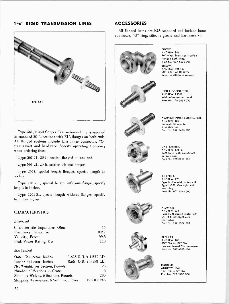
15/8" RIGID TRANSMISSION LINES ACCESSORIES
All flanged items are EIA standard and include inner connector, "0" ring, silicone grease and hardware kit.
Type 561, Rigid Copper Transmission Line is supplied in standard 20 ft. sections with EIA flanges on both ends. All flanged sections include EIA inner connector, "0" ring gasket and hardware. Specify operating frequency when ordering lines.
Type 561-11, 20 ft. section flanged on one end.
Type 561-21, 20 ft. section without flanges.
Type 2671, special length flanged, specify length in inches.
Type 2761-11, special length with one flange, specify length in inches.
Type 2761-21, special length without flanges, specify length in inches.
CHARACTERISTICS
Electrical
Characteristic Impedance, Ohms 50 Frequency Range, Gc 0.2.7 Velocity, Percent 99.8 Peak Power Rating, Kw 140
Mechanical
Outer Connector, Inches 1.625 O.D. x 1.527 I.D. Inner Conductor, Inches 0.664 O.D. x 0.588 I.D. Net Weight, per Section, Pounds 25 Number of Sections in Crate 6
Shipping Weight, 6 Sections, Pounds 290 Shipping Dimensions, 6 Sections, Inches 12 x 8 x 245
ELBOW. ANDREW 1061. 90° miter, brass construction flanged both ends. Part No. 097 5620 000
ELBOW. ANDREW 1061-3. 90° miter, no flanges. Requires 4861A couplings.
INNER CONNECTOR. ANDREW 15069. With teflon anchor bead. Part No. 126 0658 030
ADAPTOR INNER CONNECTOR. ANDREW 4851. Connects 50 ohm to 51.5 ohm line. Part No. 097 5406 000
GAS BARRIER. ANDREW 12618. With fixed male connectors on both ends. Part No. 099 0238 000
ADAPTOR. ANDREW 2261. Type N (Female), mates with Type UG21. Gas tight with vent plug. Part No. 007 7544 000
ADAPTOR. ANDREW 2361. Type LC (Female), mates with UG 154. Gas tight with vent. plug. Part No. 097 5527 000
REDUCER. ANDREW 1861. 31" EIA to 1%" EIA. Has captivated 31/8" connector. Part No. 097 6050 000
REDUCER. ANDREW 1860. 1%" EIA to%/a"EIA. Part No. 097 5405 000
56
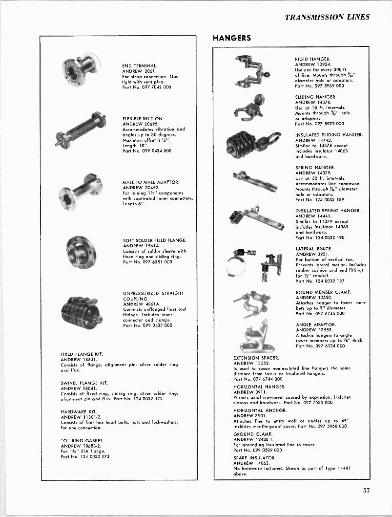
TRANSMISSION LINES
END TERMINAL. ANDREW 2061. For strap connection. Gas tight with vent plug. Part No. 097 7042 000
FLEXIBLE SECTION. ANDREW 20695. Accommodates vibration and angles up to 30 degrees. Maximum offset is 1/4".
Length 10". Part No. 099 0434 000
MALE TO MALE ADAPTOR. ANDREW 30452. For joining 1s/%" components with captivated inner connectors. Length 6".
SOFT SOLDER FIELD FLANGE. ANDREW 1561A. Consists of solder sleeve with fixed ring and sliding ring. Part No. 097 6351 000
UNPRESSURIZED STRAIGHT COUPLING. ANDREW 4861A. Connects unflanged lines and fittings. Includes inner connector and clamps. Part No. 099 0437 000
FIXED FLANGE KIT. ANDREW 18631. Consists of flange, alignment pin, silver solder ring and flux.
SWIVEL FLANGE KIT. ANDREW 18041. Consists of fixed ring, sliding ring, silver solder ring, alignment pin and flux. Part No. 124 0032 172
HARDWARE KIT. ANDREW 11381-2. Consists of four hex head bolts, nuts and lockwashers, for one connection.
"O" RING GASKET. ANDREW 10683-2. For 1%" EIA flange. Part No. 124 0032 173
HANGERS
RIGID HANGER. ANDREW 13924. Use one for every 300 ft. of line. Mounts through '" diameter hole or adaptors. Part No. 097 5969 000
SLIDING HANGER. ANDREW 14378. Use at 10 ft. intervals. Mounts through j'" hole or adaptors. Part No. 097 5972 000
INSULATED SLIDING HANGER. ANDREW 14442. Similar to 14378 except includes insulator 14063 and hardware.
SPRING HANGER. ANDREW 14379. Use at 50 ft. intervals. Accommodates line expansion. Mounts through (t" diameter hole or adaptors. Part No. 124 0032 189
INSULATED SPRING HANGER. ANDREW 14441. Similar to 14379 except includes insulator 14063 and hardware. Part No. 124 0032 190
LATERAL BRACE. ANDREW 3921. For bottom of vertical run. Prevents lateral motion. Includes rubber cushion and end fittings for Y2" conduit. Part No. 124 0032 187
ROUND MEMBER CLAMP. ANDREW 13550. Attaches hanger to tower mem- bers up to 3" diameter. Part No. 097 6745 000
ANGLE ADAPTOR. ANDREW 13555. Attaches hangers to angle tower members up to 7/e" thick. Part No. 097 6124 000
EXTENSION SPACER. ANDREW 13552. Is used to space noninsulated line hangers the same distance from tower as insulated hangers. Part No. 097 6744 000
HORIZONTAL HANGER. ANDREW 3911. Permits axial movement caused by expansion. Includes clamps and hardware. Part No. 097 7535 000
HORIZONTAL ANCHOR. ANDREW 3901. Attaches line to entry wall at angles up to 45°. Includes weatherproof cover. Part No. 097 5968 000
GROUND CLAMP. ANDREW 12430-1. For grounding insulated line to tower. Part No. 099 0509 000
SPARE INSULATOR. ANDREW 14063. No hardware included. Shown as part of Type 14441 above.
57

31/8" RIGID TRANSMISSON LINES
Type 562A Rigid Copper Transmission Line is supplied in standard 20 ft. sections with EIA flanges on both ends. All flanged sections include EIA inner connector, "O" ring gasket and hardware. Standard 19' 8" lengths are available for speical frequency applications. Specify fre- quency or channel when ordering lines.
Connectors included with straight sections are the coated type as described below.
Type 562A-11, 20 ft. section flanged on one end.
Type 562A-21, 20 ft. section without flanges.
Type 2762A-1, special length flanged, specify length in inches.
Type 2762A-11, special length with one flange, specify length in inches.
Type 2762A-21, special length without flanges, specify length in inches.
CHARACTERISTICS
Electrical
Characteristic Impedance, Ohms Frequency Range, Ge
Velocity, Percent Peak Power Rating, Kw
Mechanical
Outer Connector, Inches Inner Conducter, Inches
3.125 O.D. 1.315 O.D.
Net Weight, per Section, Pounds Number of Sections in Crate Shipping Weight, 4 Sections, Pounds Shipping Dimensions, 4 Sections, Inches
50 0-1.6 99.8 400
x 3.027 I.D. x 1.231 I.D.
55 4
425 13 x 14 x 245
ACCESSORIES
All flanged items are EIA standard and include inner connector, "0" ring, silicone grease and hardware kit.
ELBOW. ANDREW 1062. 90° miter, brass construction, flanged on both ends. Part No. 097 5621 000
ELBOW. ANDREW 1062-3. 90° miter, no flanges. Requires 4862A couplings.
COATED CONNECTOR. ANDREW 30079. Silver plated with dry baked molybdenum compound. Designed to minimize effects of expansion and contraction.
ADAPTOR INNER CONNECTOR ANDREW 4852. Connects 50 ohm to 51.5 ohm line.
INNER CONNECTOR. ANDREW 15093. With teflon anchor bead.
GAS BARRIER. ANDREW 1262. With fixed male connectors on both ends. Part No. 097 5754 000
ADAPTOR. ANDREW 2262. Type N (Female) mates with UG-21. Part No. 099 0445 000
REDUCER. ANDREW 1861. aye" EIA to 1%" EIA. Has captivated 31" connector. No. 097 6050 000
REDUCER. ANDREW 1872. 61/2" EIA to 31/4" EIA.
58
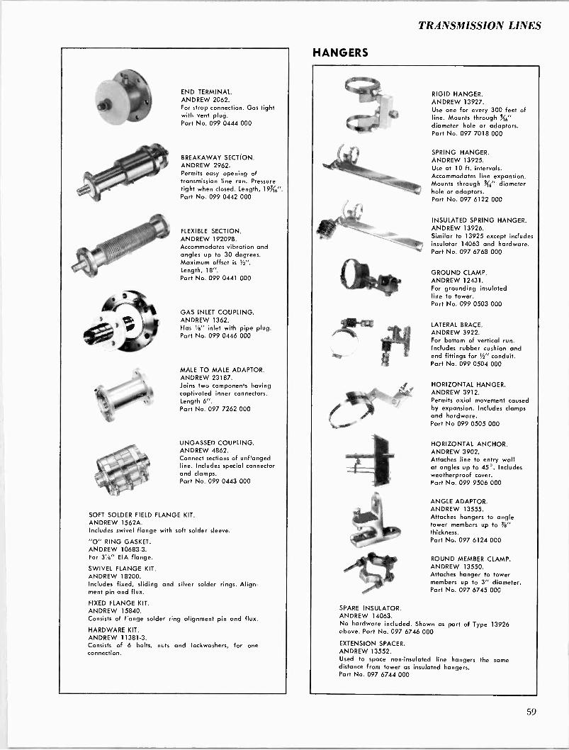
TRANSMISSION LINES
END TERMINAL. ANDREW 2062. For strap connection. Gas tight with vent plug. Part No. 099 0444 000
BREAKAWAY SECTION. ANDREW 2962. Permits easy opening of transmission line run. Pressure tight when closed. Length, 197.46".
Part No. 099 0442 000
FLEXIBLE SECTION. ANDREW 19209B. Accommodates vibration and angles up to 30 degrees. Maximum offset is 1/". Length, 18". Part No. 099 0441 000
GAS INLET COUPLING. ANDREW 1362. Has 1/2" inlet with pipe plug. Part No. 099 0446 000
MALE TO MALE ADAPTOR. ANDREW 23187. Joins two components having captivated inner connectors. Length 6". Part No. 097 7262 000
UNGASSED COUPLING. ANDREW 4862. Connect sections of unflanged line. Includes special connector and clamps. Part No. 099 0443 000
SOFT SOLDER FIELD FLANGE KIT. ANDREW 1562A. Includes swivel flange with soft solder sleeve.
"O" RING GASKET. ANDREW 10683-3. For 3t/s" EIA flange.
SWIVEL FLANGE KIT. ANDREW 18200. Includes fixed, sliding and silver solder rings. Align- ment pin and flux.
FIXED FLANGE KIT. ANDREW 15840. Consists of flange solder ring alignment pin and flux.
HARDWARE KIT. ANDREW 11381-3. Consists of 6 bolts, nuts and lockwashers, for one connection.
HANGERS
ilPrellIt
RIGID HANGER. ANDREW 13927. Use one for every 300 feet of line. Mounts through 5X6" diameter hole or adaptors. Part No. 097 7018 000
SPRING HANGER. ANDREW 13925. Use at 10 ft. intervals. Accommodates line expansion. Mounts through 946" diameter hole or adaptors. Part No. 097 6122 000
INSULATED SPRING HANGER. ANDREW 13926. Similar to 13925 except includes insulator 14063 and hardware. Part No. 097 6768 000
GROUND CLAMP. ANDREW 12431. For grounding insulated line to tower. Part No. 099 0503 000
LATERAL BRACE. ANDREW 3922. For bottom of vertical run. Includes rubber cushion and end fittings for t/s" conduit. Part No. 099 0504 000
HORIZONTAL HANGER. ANDREW 3912. Permits axial movement caused by expansion. Includes clamps and hardware. Part No 099 0505 000
HORIZONTAL ANCHOR. ANDREW 3902. Attaches line to entry wall at angles up to 45°. Includes weatherproof cover. Part No. 099 9506 000
ANGLE ADAPTOR. ANDREW 13555. Attaches hangers to angle tower members up to 7/s" thickness. Part No. 097 6124 000
ROUND MEMBER CLAMP. ANDREW 13550. Attaches hanger to tower members up to 3" diameter. Part No. 097 6745 000
SPARE INSULATOR. ANDREW 14063. No hardware included. Shown as part of Type 13926 above. Part No. 097 6746 000
EXTENSION SPACER. ANDREW 13552. Used to space non -insulated line hangers the same distance from tower as insulated hangers. Part No. 097 6744 000
59
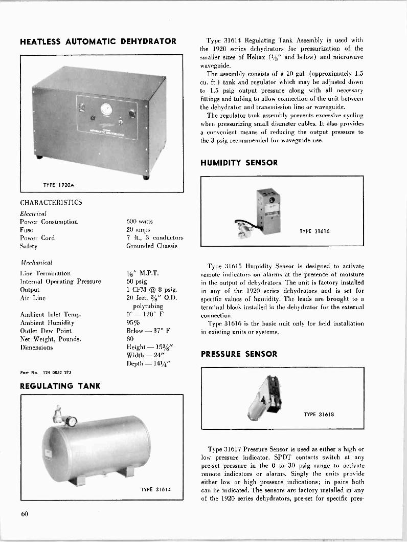
HEATLESS AUTOMATIC DEHYDRATOR
CHARACTERISTICS
Electrical Power Consumption Fuse Power Cord Safety
Mechanical
Line Termination Internal Operating Pressure Output Air Line
Ambient Inlet Temp. Ambient Humidity Outlet Dew Point Net Weight, Pounds. Dimensions
Part No. 124 0032 273
REGULATING TANK
600 watts 20 amps 7 ft., 3 conductors Grounded Chassis
1/8" M.P.T. 60 psig 1 CFM @ 8 psig. 20 feet, %" O.D.
polytubing 0° - 120° F 95% Below - 37° F 80 Height -153/8" Width - 24" Depth -141/.1"
Type 31614 Regulating Tank Assembly is used with the 1920 series dehydrators for pressurization of the smaller sizes of Heliax (1/2" and below) and microwave waveguide.
The assembly consists of a 10 gal. (approximately 1.5
cu. ft.) tank and regulator which may be adjusted down to 1.5 psig output pressure along with all necessary fittings and tubing to allow connection of the unit between the dehydrator and transmission line or waveguide.
The regulator tank assembly prevents excessive cycling when pressurizing small diameter cables. It also provides a convenient means of reducing the output pressure to
the 3 psig recommended for waveguide use.
HUMIDITY SENSOR
TYPE 31616
Type 31615 Humidity Sensor is designed to activate remote indicators on alarms at the presence of moisture in the output of dehydrators. The unit is factory installed in any of the 1920 series dehydrators and is set for specific values of humidity. The leads are brought to a
terminal block installed in the dehydrator for the external connection.
Type 31616 is the basic unit only for field installation in existing units or systems.
PRESSURE SENSOR
Type 31617 Pressure Sensor is used as either a high or low pressure indicator. SPDT contacts switch at any pre-set pressure in the 0 to 30 psig range to activate remote indicators or alarms. Singly the units provide either low or high pressure indications; in pairs both can be indicated. The sensors are factory installed in any of the 1920 series dehydrators, pre-set for specific pres-
60
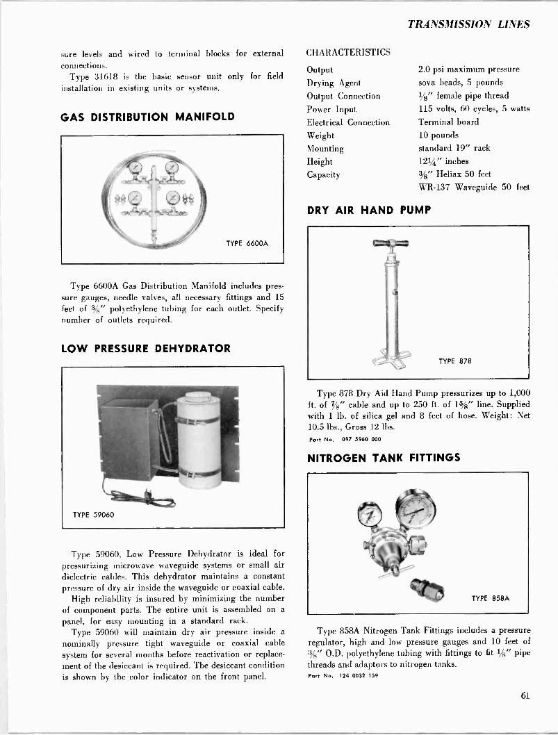
TRANSMISSION LINES
sure levels and wired to terminal blocks for external connections.
Type 31618 is the basic sensor unit only for field
installation in existing units or systems.
GAS DISTRIBUTION MANIFOLD
Type 6600A Gas Distribution Manifold includes pres- sure gauges, needle valves, all necessary fittings and 15
feet of 3/8" polyethylene tubing for each outlet. Specify number of outlets required.
LOW PRESSURE DEHYDRATOR
Type 59060, Low Pressure Dehydrator is ideal for pressurizing microwave waveguide systems or small air dielectric cables. This dehydrator maintains a constant pressure of dry air inside the waveguide or coaxial cable.
High reliability is insured by minimizing the number of component parts. The entire unit is assembled on a
panel, for easy mounting in a standard rack. Type 59060 will maintain dry air pressure inside a
nominally pressure tight waveguide or coaxial cable system for several months before reactivation or replace- ment of the desiccant is required. The desiccant condition is shown by the color indicator on the front panel.
CHARACTERISTICS
Output
Drying Agent
Output Connection
Power Input Electrical Connection
Weight Mounting
Height
Capacity
DRY AIR HAND
2.0 psi maximum pressure
soya beads, 5 pounds
1/8" female pipe thread 115 volts, 60 cycles, 5 watts
Terminal board
10 pounds
standard 19" rack
121/4" inches
3/8" Heliax 50 feet
WR -137 Waveguide 50 feet
PUMP
Type 878 Dry Aid Hand Pump pressurizes up to 1,000 ft. of 7/8" cable and up to 250 ft. of 15/8" line. Supplied with 1 lb. of silica gel and 8 feet of hose. Weight: Net 10.5 lbs., Gross 12 lbs.
Part No. 097 5960 000
NITROGEN TANK FITTINGS
Type 858A Nitrogen Tank Fittings includes a pressure regulator, high and low pressure gauges and 10 feet of 3/8" O.D. polyethylene tubing with fittings to fit 1/8" pipe threads and adaptors to nitrogen tanks. Part No. 124 0032 159
61

PRESSURIZATION FITTINGS AND ACCESSORIES
iUi . &.Wemrr.+r .
GAS INLET VALVE ANDREW 3017 Has 1/e" male pipe thread. Part No. 013 0365 000
PRESSURE GAUGE ANDREW 3500 Reads 0-20 psi and has 1/8" male pipe thread. Indoor use only. Part No. 013 0366 000
RELEASE VALVE ANDREW 3027 Has 1/8" male pipe thread on one end. Part No. 013 0368 000
RELEASE VALVE ANDREW 4944 Has 1/8" male pipe threads on both ends. Part No. 013 0728 000
RELEASE VALVE ANDREW 4949 Has 1/8" pipe threads, male one end, female, other end. Part No. 013 0730 000
MALE CONNECTOR ANDREW 31680-1 For 3/e" poly tubing, has 1/8"
male pipe threads one end.
MALE CONNECTOR ANDREW 31680-2 For 3/8" poly tubing, has lá" male pipe threads one end.
MALE BRANCH TEE
ANDREW 31680-3 For 3/e" poly tubing, has !4" male pipe threads on one outlet.
MALE RUN TEE
ANDREW 31680-5 For
3/8 poly tubing, has !é"
male pipe threads on one outlet.
ELBOW ANDREW 25436-4 For 3/s" poly tubing, has Vs" male pipe threads one end.
PIPE TEES
ANDREW 3016 Part No. 013 0364 000 Has Vs" female pipe threads each outlet. ANDREW 3022 Part No.013 0701 000 Has one male and 2 female 1/e" pipe thread outlets.
PIPE PLUG ANDREW 3018 Part No. 013 0367 000 Has 1/e" male pipe thread.
PIPE NIPPLES Threaded entire length. ANDREW 3026 Part No. 013 0703 000 '/e" male pipe threads.
ANDREW 25436-12 '4" male pipe threads.
THREAD LUBRICANT ANDREW 3012 Part No. 013 0272 000 4 cc. tube.
VINYL TAPE ANDREW 9905-18 20 ft. by 3/4" wide.
SPARE HOSE ASSEMBLY ANDREW 10195 Is 7 ft. long for Type 878 pump.
SILICA GEL REFILL ANDREW 210 Part No. 013 0439 000 One pound package.
POLYETHYLENE TUBING ANDREW 25435 ?é" diameter.
MOUNTING STRAP ANDREW 31712 For 3/8" poly tubing.
COPPER TUBING ANDREW 10741-2 14" diameter, soft temper.
COUPLING ANDREW 10994-4 For 3/4" tubing, has flared fitting on one end and /e" male pipe thread on the other end.
FLARE COUPLING ANDREW 10994-2 For 3/4" tubing.
SPLICING SLEEVE ANDREW 12129 Solders to 3/4" tubing.
COUPLING ANDREW 4947 Part No. 013 0729 000 Solders to 14" tubing, has 1/8" male pipe thread.
62
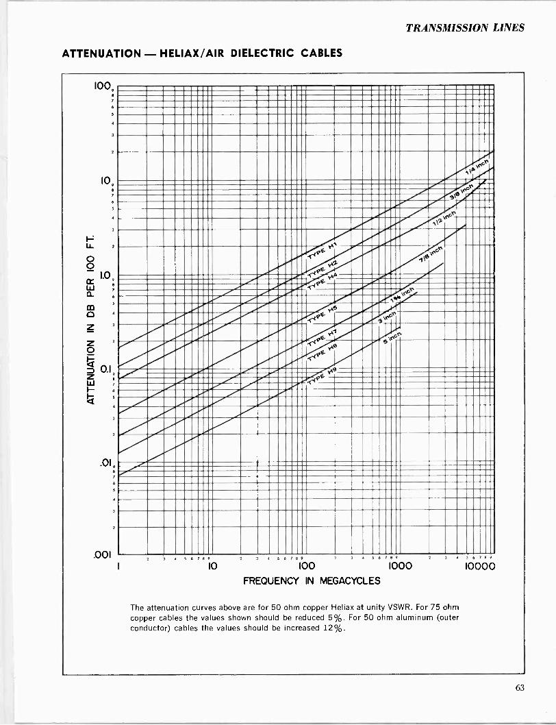
TRANSMISSION LINES
ATTENUATION - HELIAX/AIR DIELECTRIC CABLES
100,
6
10,
2
1.0
7
6
S
3
2
0.1 9
e
s
3
2
.0I
5
7
2
.001
G .r°r
g\
0` IMMOOP'_ _-- ,s -w''-' ' 6
rcr
cr
4 6 9
10 2 J 4 5 6 .8 9 4 5 6 8 9 2
100 1000 FREQUENCY IN MEGACYCLES
3 5 6 ] 8 4
10000
The attenuation curves above are for 50 ohm copper Heliax at unity VSWR. For 75 ohm copper cables the values shown should be reduced 5%. For 50 ohm aluminum (outer conductor) cables the values should be increased 12%.
63

POWER RATING - HELIAX/AIR DIELECTRIC CABLES
10009 °
6
4
3
2
100,
6
4
3
J ° 2
6
5
2
0.19
6
.01
11}{1 1 11 I I 1
PEAK POWER RATINGS These ratings are constant with frequency and are based on unity VSWR, no modulation, and one atmosphere absolute dry air pressure.
113
IS
LINE SIZE, TYPE PEAK POWER INCHES NO. RATING, kw
allillibillikl 21___a__ all
5 H9-50 830 3
13/4 405
7 8 H5 -50A 1444
1/2 H4 3/8 H2-50 5
1/4 H1-50 2 3 ". ".413111 OM
YA "n \Z\1 \ \M F A:9 _ffl
____ 1.1 -intima imman. 'III uuiliia IÌ !!B\II ';, "n ye -'\,1;Ì
111111 '11 i _,\,1;Ìï
`'11 ,\ '1 11 IIIIII \____ mmmzn
IQ_. iiMM 'MM.. ___ M1.1fM11 mean
Mili.91 _ '3U ___.MM MIM- `_BIZIZIBfflI...IIr___uu MIUI! \IN SMIIIIIl Mti. III IÍ1,! II MN 111 '%
1111 Ills 1111ÌI\\' Illlii _____..0
=Mu 11 dill
r ° kiii IIII s 11 Iilll 11 N " aa
h -mai 1M --- moi? M 'í111I MI1Z!1 MIM I 111 9i 11I
mom Bum ffl rUII IZbINI l)F
11, ,l
1
.111;
II11111MBEh'' 1111 1111 1188MM epeeaaaaaaaaaaalllleeaaalllll\Naelllaall ea . 'e, g IMI11MM1 I__Z fflIIMMINI RIIIMMIOR I-- Acr __...... 11111I __....u. __II ___B M_N..u. .u __I -- -noon R111illMII_. ray II I ch
2 3 4 5 6 7° 10
3 4 5 6 ° 9 2
100 6 2 ° 9 2
1000
FREQUENCY IN MEGACYCLES
3 4 6 1 9
10000
The average power ratings shown above are for 50 ohm copper Heliax and are based
on unity VSWR and a maximum inner conductor temperature of 212°F at an ambient temperature of 104°F. For 75 ohm copper cables the values shown should be reduced
30%. For 50 ohm aluminum (outer conductor) cables the values should be reduced
10%. For Teflon insulated cables, average power ratings should be increased by 35%.
64
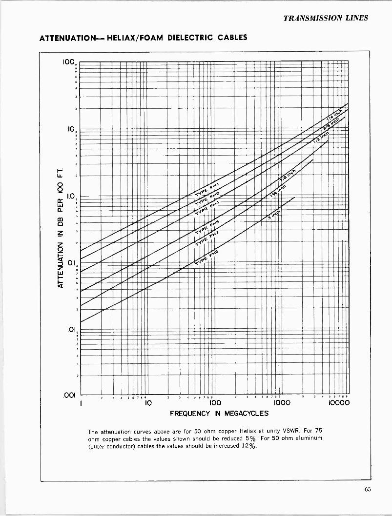
TRANSMISSION LINES
ATTENUATION- HELIAX/FOAM DIELECTRIC CABLES
100, e
7
6
5
3
2
109 8
7
6
5
3
LI_ 2
o o
W Q
Z 3
Z 7
o p z 0.1 Z 8
W 7
6
Q 5
3
7
6
3
.001 2 3 5 6 8 9 2 3 4 5 6 7 8 9 4 5 6 7 8 9 2
10 100
FREQUENCY IN MEGACYCLES
1000 3 5 6 7 8 9
10000
The attenuation curves above are for 50 ohm copper Heliax at unity VSWR. For 75
ohm copper cables the values shown should be reduced 5%. For 50 ohm aluminum
(outer conductor) cables the values should be increased 12%.
65
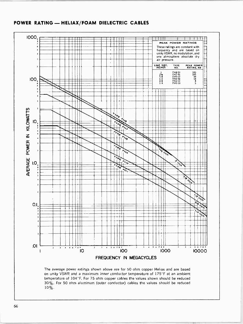
POWER RATING - HELIAX/FOAM DIELECTRIC CABLES
1000, 7
6
5
4
3
7
100, 7
5
3
of 10
X 7 e
5
w
LL
w á 1.0,
4
7
0.1, 8
.01
{1111 1 I 1 11{h-. PEAK POWER RATINGS
These ratings are constant with frequency and are based on unity VSWR, no modulation, and one atmosphere absolute dry air pressure.
_ - - - LINE SIZE, TYPE PEAK POWER
INCHES NO. RATING, kw
3 FH8-50 320 11/4 FH7-50 145
FH5-50 44 FH4-50 FH2-50 FH1-50 5 il -
T> k.
T e 11111111
A F y R1 ion > YA F
I 1 %
Il
7 cy Ati4 _, 'ch ÁE \ = ' AA 7
11111-Ighl.41111h >/el
Bch
h
-^9e Oe
4 5 6 7 8 V
10 4 5 6 8 G
100 4 5 6 7 9 2
1000
FREQUENCY IN MEGACYCLES
3 4 5 A 8 V
10000
The average power ratings shown above are for 50 ohm copper Heliax and are based on unity VSWR and a maximum inner conductor temperature of 175°F at an ambient temperature of 104°F. For 75 ohm copper cables the values shown should be reduced 30%. For 50 ohm aluminum (outer conductor) cables the values should be reduced 10%.
66
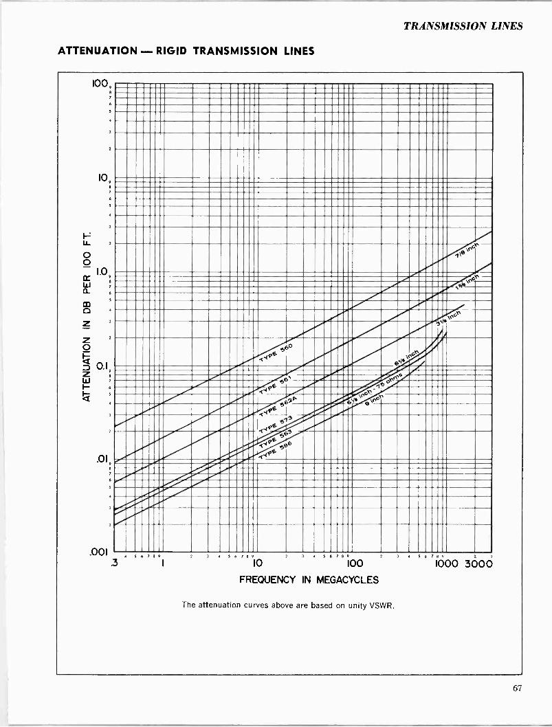
TRANSMISSION LINES
ATTENUATION - RIGID TRANSMISSION LINES
100,
6
5
109 8
6
1.0 9
8
6
2
0.1 9
8
5
2
.019
.001 5 6 7 8 9
Ildlellii ' /ZIMONZIMIIIII/ s
IlfflMMBEIMPIP G ,
,°°:+1x"
3 4 5 6 8 0
10 4 5 6 l
100
FREQUENCY IN MEGACYCLES
The attenuation curves above are based on unity VSWR.
3 4 5 6 8 0 2 3
1000 3000
67
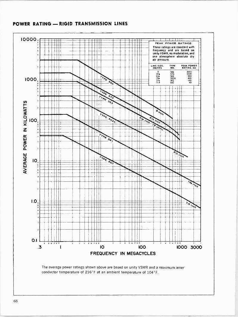
POWER RATING - RIGID TRANSMISSION LINES
100009 7
6
5
3
2
10009 8
6
5
4
3
2
109 8
7
6
5
3
1.09
01
2
PEAK POWER RATINGS These ratings are constant with frequency and are based on unity VSWR, no modulation, and one atmosphere absolute dry air pressure.
1
LINE SIZE, TYPE PEAK POWER INCHES NO. RATING, kw
9 586 3000 64e 573 1500 64e 563 890 31/e 562A 400 15/4 561 140 7/8 560 43
s 4 7n s 7n
ch ch
s_
1
.3 5 6 7 13 9 5 6 8 9 4 5 6 7 9 2
10 100
FREQUENCY IN MEGACYCLES
5 6 8 9 2 3
1000 3000
The average power ratings shown above are based on unity VSWR and a maximum inner conductor temperature of 216°F at an ambient temperature of 104°F.
e
68
Audio Facilities
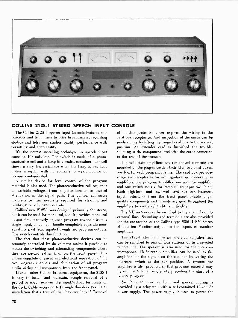
COLLINS 212S-1 STEREO SPEECH INPUT The Collins 212S-1 Speech Input Console features new
concepts and techniques to offer broadcasters, recording studios and television studios quality performance with versatility and adaptability.
It's the newest switching technique in speech input consoles. It's noiseless. The switch is made of a photo- conductive cell and a lamp in a sealed container. The cell shows a very low resistance when the lamp is on. This makes a switch with no contacts to wear, bounce or become contaminated.
A similar device for level control of the program material is also used. The photoconductive cell responds to variable voltages from a potentiometer to control attenuation in the signal path. This control eliminates maintenance time normally required for cleaning and relubrication of mixer controls.
Collins' new 212S-1 was designed primarily for stereo, but it can be used for monaural, too. It provides monaural output simultaneously on both program channels from a
single input, or you can handle completely separate mon- aural material from inputs through two program outputs. One switch controls this function.
The fact that these photoconductive devices can be remotely controlled by dc voltages makes it possible to mount the switching and attenuating components where they are needed rather than on the front panel. This allows complete physical and electrical separation of the two program channels and elimination of all program audio wiring and components from the front panel.
Like all other Collins broadcast equipment, the 212S-1 is easy to install and maintain. Simple removal of a
protective cover exposes the input/output terminals on the deck. Cable access ports through this deck permit an installation that's free of the "haywire look"! Removal
CONSOLE of another protective cover exposes the wiring to the card box receptacles. And inspection of the cards can be made simply by lifting the hinged card box to the vertical position. An extender card is furnished for trouble- shooting at the component level with the cards connected to the rest of the console.
The solid-state amplifiers and the control elements are mounted on the plug-in cards which fit in two card boxes, one box for each program channel. The card box provides space and receptacles for six high-level or low-level pre- amplifiers, one program amplifier, one monitor amplifier and one switch matrix for remote line input switching. Each high-level and low-level card has two balanced inputs selectable from the front panel. Stable, high - quality components and circuits are used throughout the amplifiers to assure reliability and fidelity.
The VU meters may be switched to the channels or to external lines. Switching and terminals are also provided for the connection of the Collins type 900C-1 FM Stereo Modulation Monitor outputs to the inputs of monitor amplifiers.
The 212S-1 also includes an intercom amplifier that can be switched to one of four stations or to a selected remote line. The speaker is also used for the intercom microphone. Th intercom amplifier can be used as the amplifier for the signals on the cue bus by setting the intercom switch at the cue position. A reverse cue amplifier is also provided so that program material may be sent back to a remote site preceding the start of a remote program.
Switching for warning light and speaker muting is provided by a relay unit with a self-contained 12 -volt dc power supply. The power supply is used to power the
70
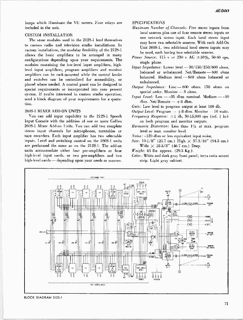
AUDIO
lamps which illuminate the VU meters. Four relays are included in the unit.
CUSTOM INSTALLATION The same modules used in the 212S-1 lend themselves
to custom radio and television studio installations. In custom installations, the modular flexibility of the 212S-1 allows the basic amplifiers to be arranged in many configurations depending upon your requirements. The modules containing the low-level input amplifiers, high- level input amplifiers, program amplifiers and monitor amplifiers can be rack -mounted while the control knobs and switches can be centralized for accessibility, or placed where needed. A control panel can be designed to special requirements or incorporated into your present system. If you're interested in custom studio operation, send a block diagram of your requirements for a quota- tion.
260S-1 MIXER ADD-ON UNITS You can add input capability to the 212S-1 Speech
Input Console with the addition of one or more Collins 260S-1 Mixer Add-on Units. You can add two complete stereo input channels for microphones, turntables or tape recorders. Each input amplifier has two selectable inputs. Level and switching control on the 260S-1 units are performed the same as on the 212S-1. The add-on units accommodate either four pre -amplifiers or four high-level input cards, or two pre -amplifiers and two high-level cards - depending upon your needs or sources.
SPECIFICATIONS Maximum Number of Channels: Five stereo inputs from
local sources plus one of four remote stereo inputs or one network stereo input. Each local stereo input may have two selectable sources. With each Add -On Unit 260S-1, two additional local stereo inputs may be used, each having two selectable sources.
Power Source: 115 v or 230 v AC ±10%, 50-60 cps, single phase.
Input Impedance: Lower level - 30/150/250/600 ohms, balanced or unbalanced. Net/Remote - 600 ohms balanced. Medium level - 600 ohms balanced or unbalanced.
Output Impedance: Line - 600 ohms. 150 ohms on special order. Monitor -8 ohms.
Input Level: Low - -55 dbm nominal. Medium - -10 dbm. Net/Remote - +8 dbm.
Gain: Low level to program output at least 100 db. Output Level: Program - +8 dbm. Monitor -10 watts. Frequency Response: ±1 db, 30-15,000 cps (ref. 1 kc)
on both program and monitor outputs. Harmonic Distortion: Less than 1% at max. program
level or max. monitor level. Noise: -120 dbm or less equivalent input noise. Size: 10-1/8" (25.7 cm.) High X 37-3/16" (94.5 cm.)
Wide X 18-3/8" (46.7 cm.) Deep. Weight: 65 lbs. approx. (29.5 Kg.). Color: White and dark gray front panel; terra cotta accent
strip. Light gray cabinet.
/FAO SET
la
LEFT CHANNEL INPUTS
356 - PREAMP
OR
356V -
HI LEVEL
8
b
REMOTE
.11 "ú -1O I1RM
Y Y - 3561.1 - PREAIMP - 356T-1 3840 1 SM CH
OR - PREAMP MATRIX
.. -. .. 356V1 MLEVEL
ARO
-45 -45
`i
8
.APP (i7401(p
INTERCOM
RUA
SW
CUL IUS
òti
CIA 5W CUE SW
ab CUE SW CUE
It
BUD BUS
PRO;
-45 BRM
5611 REAM -. 56V 1 -. HI LEVEL
TYP
T.
PREAMP
TIP OR
356Y - NI LEVEL
^ 8 Á B
l 356VI I LEVEL
O
3846 MATCH
MATRA
)i,444 '1".
RFMOR
-45 ORM
RAViT CHANNEL INPUTS
RASTER
CH.I
3P-1 PROGRAM
M EURER CH. I
prm
SIMA
+l4 BRM +8 BRM
üi4
356 -1 PROGRAM AMPLHER a.
MASTER
EST
fVUM (11
FROG/UM l6T
4}nd'
Qp41T o
MONIOR356
M-1
OUTS (LIFT)
356 M-1 room KW" -1---our (MALO (RIGHT)
+14 DOM +8 BRM
0
BLOCK DIAGRAM 212S -I
71

COLLINS 212M-1 SPEECH INPUT CONSOLE
The 212M-1 is the monaural equivalent of the 212S-1 Stereo Console. Utilizing the source modules in a lesser quantity, the broadcaster can realize the same reliability, fidelity and operational features as described above by the 212S-1.
SPECIFICATIONS Maximum Number of Channels: Five mono inputs from
local sources plus one of four remote inputs or one network input. Each local input may have two select- able sources. With each Add -On Unit 260A-1, two additional local inputs may be used, each having two selectable sources.
Power Source: 115 v or 230 single phase.
Input Impedance: Low level balanced or unbalanced. balanced. Medium level unbalanced.
v AC ±10%, 50-60 cps.
- 30/150/250/600 ohms, Net/Remote - 600 ohms - 600 ohms balanced or
Output Impedance: Line - 600 ohms. 150 ohms on special order. Monitor -8 ohms.
Input Level: Low - -55 dbm nominal. Medium - -10 dbm. Net/Remote - +8 dbm.
Gain: Low level to program output at least 100 db.
Output Level: Program - +8 dbm. Monitor -10 watts.
Frequency Response: ±1 db, 30-15,000 cps (ref. 1 kc) on both program and monitor outputs.
Harmonic Distortion: Less than 1% at max. program level or max. monitor level.
Noise: -120 dbm or less equivalent input noise.
Size: 101/8" (25.7 cm.) High x 37-3/16" (94-5 cm.) Wide x 18%" (46.7 cm.) Deep.
Color: White and dark gray front panel; terra cotta accent strip. Light gray cabinet.
Weight: 75 lbs.
CUE SW.
INPUTS
A B A B
CUE S CUE SW
3ST1 PREAMP
OR jLO-
n ? AIR
356V.1 HI LEVEL AIB A 18 .0 .O
AIP AIP .0e
AIP
PROD BUS
AUG BUS
TV
A B A B
CUE SW. 1 1
03E SW.
n
- 356T 1
PAEAMP OA
356V1 A' e NI LEVEL .-o.
AIP .O
IS DBM
NET V
356i.1 PREAMP
38/01 SWITCH
MATRIX
M-
I IMI%I
MONITOR
MON
_REM
.45 OM
CUE BU
HEADSET
RBI IC, I ,NET
OFF- 9ZZI -P
AMPL
MASTER GAIN
Y DIRECTI
PROGRAM 3%PI
AMPLIFIER
O
INTERCOM
A
CE
NEM-
OFF
4!)
o
VU
EXT EXT
N
PAD ; D OGBA PRM OOT
AUD. PROG
OFF- -EXT
-- EXTERNAL
a''''MDN MONITOR INPUT
cAlx, I
PAD
3S61F1
MONITOR AMPLIFIER
MONITOR OUT
NTERO)U
o
(
AMPL
BLOCK DIAGRAM 212M-1
72

AUDIO
COLLINS 356T-1 PREAMPLIFIER
Illlllililllli`
The 356T-1 is used with the 212S-1 and 212M-1 consoles in input channels where microphones are to be utilized.
SPECIFICATIONS Input Impedance: 600, 250, 150, 30 choice, factory wired
for 150. Balanced.
Gain: Total 50 DB voltage gain, -65 DBM from mic. will deliver -45 DBM to input to program amplifier. (Includes mixer loss.)
Noise: E. I. N. 120 DBM.
Output Impedance: Direct 150 ohms. Program >10K ohms - 25 DB mixing loss.
Outputs: 1. Direct 3. Audition 2. Program 4. Cue
Inputs: MIC 1 Max. IN = -30DBM MIC 2 Max. IN = -30DBM
Power Requirements: +30 VDC Regulated at 5 MA +6 6 VDC Regulated at 60 MA
Attenuator & (1 lamp) Switch Lamps +4 VDC Regulated at 120 MA
(3 lamps) Frequency Response: ±.5 DB from 30 cps to 15 KC.
(ref. to 1 KC)
Harmonic Distortion: 0.5% max. at rated output. Temperature Limits: 0° to 50° C.
Size: 4" x 6" plug-in card; 1" max. component height. Adjustments: Trim Pot for tracking attenuators. Attenuator: Photo -cell lamp unit built into circuit board.
0 VDC to 6 VDC (controlled by external series variable resistor*) attenuates signal over a 55 DB range.
Switches: Photo -cell lamp unit used for all audio circuit switching.
*One variable resistor may be used to control attenuation of two Preamps. Preamps track within ± DB.
356V-1 HIGH LEVEL INPUT PREAMPLIFIER
The 356V-1 is required for input channels for the 212S-1 and 212M-1 consoles where outputs of the turn- table preamplifier, tape recorders, and other equipments with audio outputs between -10 DBM and +10 DBM are fed into the console.
SPECIFICATIONS Input Impedance: 600 ohms, balanced. Gain: -10 DBM input will deliver -45 DBM to input of
program amplifier. (Includes mixer loss) 30 DB pad on input.
Output Impedance: Direct 15 ohms. Program: >10K ohms - 25 db mixing loss Outputs: 1. Direct 3. Audition
2. Program 4. Cue Inputs: IN 1: Maximum input = +10 DBM Inputs: IN 2: Maximum input = +10 DBM
Power Requirements: +30 VDC at 5 MA +6 VDC at 60 MA Regulated
Attenuator & (1 lamp) Switch Lamps +4 VDC at 120 MA Regulated
(3 lamp) Frequency Response: ±.5 DB from 30 cps to 15 kcps
(Ref. to 1 KC) Harmonic Distortion: 0.5% maximum at rated output. Temperature Limits: 0° to +50°C. Size: 4" x 6" plug-in card; 1" maximum component
height. Adjustments: Trim -pot for Tracking Attenuators. Attenuator: Photo -cell lamp unit built into circuit board.
0 VDC to 6 VDC (controlled by external series variable resistor*) attenuates signal over a 55 DB range.
Switches: Photo -cell lamp unit used for all audio circuit switching.
*One variable resistor may be used to control attenuation of two hi -level inputs. Tracking is within ±1 db.
73
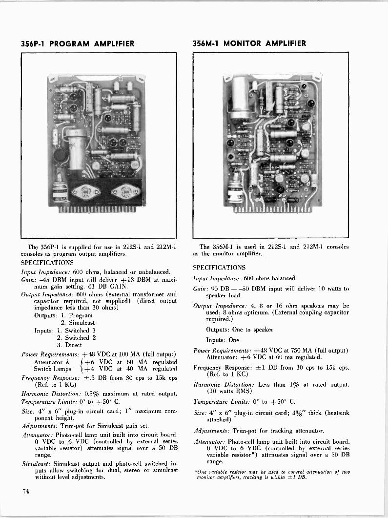
356P-1 PROGRAM AMPLIFIER
The 356P-1 is supplied for use in 212S-1 and 212M-1 consoles as program output amplifiers.
SPECIFICATIONS Input Impedance: 600 ohms, balanced or unbalanced. Gain: -45 DBM input will deliver +18 DBM at maxi-
mum gain setting. 63 DB GAIN. Output Impedance: 600 ohms (external transformer and
capacitor required, not supplied) (direct output impedance less than 30 ohms) Outputs: L Program
2. Simulcast Inputs: 1. Switched 1
2. Switched 2 3. Direct
Power Requirements: +48 VDC at 100 MA (full output) Attenuator & f +6 VDC at 60 MA regulated Switch Lamps 1+4 VDC at 40 MA regulated
Frequency Response: ±.5 DB from 30 cps to 15k cps (Ref. to 1 KC)
Harmonic Distortion: 0.5% maximum at rated output. Temperature Limits: 0° to +50° C.
Size: 4" x 6" plug-in circuit card; 1" maximum com- ponent height.
Adjustments: Trim -pot for Simulcast gain set.
Attenuator: Photo -cell lamp unit built into circuit board. 0 VDC to 6 VDC (controlled by external series variable resistor) attenuates signal over a 50 DB range.
Simulcast: Simulcast output and photo -cell switched in- puts allow switching for dual, stereo or simulcast without level adjustments.
356M-1 MONITOR AMPLIFIER
The 356M-1 is used in 212S-1 and 212M-1 consoles as the monitor amplifier.
SPECIFICATIONS
Input Impedance: 600 ohms balanced.
Gain: 90 DB - -50 DBM input will deliver 10 watts to speaker load.
Output Impedance: 4, 8 or 16 ohm speakers may be used; 8 ohms optimum. (External coupling capacitor required.)
Outputs: One to speaker
Inputs: One
Power Requirements: +48 VDC at 750 MA (full output) Attenuator: +6 VDC at 60 ma regulated.
Frequency Response: ±1 DB from 30 cps to 15k cps. (Ref. to 1 KC)
Harmonic Distortion: Less than 1% at rated output. (10 watts RMS)
Temperature Limits: 0° to +50° C.
Size: 4" x 6" plug-in circuit card; 3%" thick (heatsink attached)
Adjustments: Trim -pot for tracking attenuator.
Atten'uator: Photo -cell lamp unit built into circuit board. 0 VDC to 6 VDC (controlled by external series variable resistor*) attenuates signal over a 50 DB range.
*One variable resistor may be used to control attenuation of two monitor amplifiers, tracking is within ±1 DB.
74
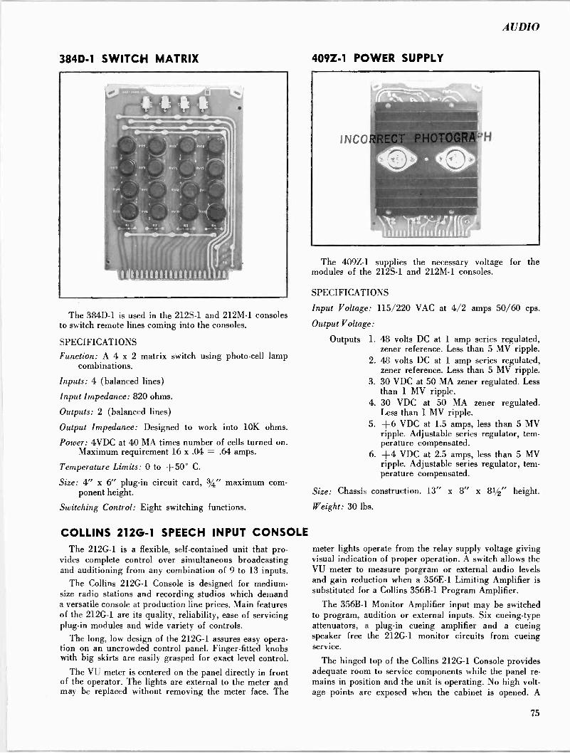
AUDIO
384D-1 SWITCH MATRIX
The 384D-1 is used in the 212S-1 and 212M-1 consoles to switch remote lines coming into the consoles.
SPECIFICATIONS
Function: A 4 x 2 matrix switch using photo -cell lamp combinations.
Inputs: 4 (balanced lines)
Input Impedance: 820 ohms.
Outputs: 2 (balanced lines)
Output Impedance: Designed to work into 10K ohms.
Power: 4VDC at 40 MA times number of cells turned on. Maximum requirement 16 x .04 = .64 amps.
Temperature Limits: 0 to +500 C.
Size: 4" x 6" plug-in circuit card, 3/4" maximum com- ponent height.
Switching Control: Eight switching functions.
COLLINS 212G-1 SPEECH INPUT CONSOLE The 212G-1 is a flexible, self-contained unit that pro-
vides complete control over simultaneous broadcasting and auditioning from any combination of 9 to 13 inputs.
The Collins 212G-1 Console is designed for medium - size radio stations and recording studios which demand a versatile console at production line prices. Main features of the 212G-1 are its quality, reliability, ease of servicing plug-in modules and wide variety of controls.
The long, low design of the 212G-1 assures easy opera- tion on an uncrowded control panel. Finger -fitted knobs with big skirts are easily grasped for exact level control.
The VU meter is centered on the panel directly in front of the operator. The lights are external to the meter and may be replaced without removing the meter face. The
409Z-1 POWER SUPPLY
The 409Z-1 supplies the necessary voltage for the modules of the 212S-1 and 212M-1 consoles.
SPECIFICATIONS
Input Voltage: 115/220 VAC at 4/2 amps 50/60 cps.
Output Voltage:
Outputs 1. 48 volts DC at 1 amp series regulated, zener reference. Less than 5 MV ripple.
2. 4.8 volts DC at 1 amp series regulated, zener reference. Less than 5 MV ripple.
3. 30 VDC at 50 MA zener regulated. Less than 1 MV ripple.
4. 30 VDC at 50 MA zener regulated. Less than 1 MV ripple.
5. +6 VDC at 1.5 amps, less than 5 MV ripple. Adjustable series regulator, tem- perature compensated.
6. +4 VDC at 2.5 amps, less than 5 MV ripple. Adjustable series regulator, tem- perature compensated.
Size: Chassis construction. 13" x 8" x 81/2" height.
Weight: 30 lbs.
meter lights operate from the relay supply voltage giving visual indication of proper operation. A switch allows the VU meter to measure porgram or external audio levels and gain reduction when a 356E-1 Limiting Amplifier is substituted for a Collins 356B-1 Program Amplifier.
The 356B-1 Monitor Amplifier input may be switched to program, audition or external inputs. Six cueing -type attenuators, a plug-in cueing amplifier and a cueing speaker free the 212G-1 monitor circuits from cueing service.
The hinged top of the Collins 212G-1 Console provides adequate room to service components while the panel re- mains in position and the unit is operating. No high volt- age points are exposed when the cabinet is opened. A
75
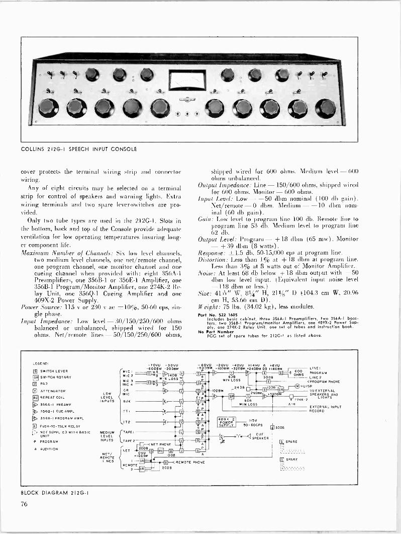
COLLINS 212G -I SPEECH INPUT CONSOLE
cover protects the terminal wiring strip and connector wiring.
Any of eight circuits may be selected on a terminal strip for control of speakers and warning lights. Extra wiring terminals and two spare lever -switches are pro- vided.
Only two tube types are used in the 212G-1. Slots in the bottom, back and top of the Console provide adequate ventilation for low operating temperatures insuring long- er component life. Maximum Number o/ Channels: Six low level channels,
two medium level channels, one net/remote channel, one program channel, one monitor channel and one cueing channel when provided with: eight 356A-1 Preamplifiers, one 356B-1 or 356E-1 Amplifier, one 356B-1 Program/Monitor Amplifier, one 274K-2 Re- lay Unit, one 356Q-1 Cueing Amplifier and one 409X-2 Power Supply.
Power Source: 115 IT or 230 v ac ±10%, 50-60 cps, sin- gle phase.
Input Impedance: Low level - 30/150/250/600 ohms balanced or unbalanced, shipped wired for 150 ohms. Net/remote lines - 50/150/250/600 ohms,
shipped wired for 600 ohms. Medium level - 600 ohms unbalanced.
Output Impedance: Line -150/600 ohms, shipped wired for 600 ohms. Monitor - 600 ohms.
Input Level: Low - -50 dbm nominal (100 db gain). Net/remote -0 dbm. Medium - -10 dbm nom- inal (60 db gain).
Gain: Low level to program line 100 db. Remote line to program line 53 db. Medium level to program line 62 db.
Output Level: Program -+ 18 dbm (65 mw) . Monitor - +39 dbm (8 watts). Response: ±1.5 db, 50-15,000 cps at program line. Distortion: Less than 1% at + 18 dbm at program line.
Less than 3% at 8 watts out of Monitor Amplifier. Noise: At least 68 db below + 18 dbm output with -50
dbm low level input. (Equivalent input noise level - 118 dbm or less.) Size: 41h" W, 81/4" H, 211/8" D (104.3 cm W, 20.96
cm H, 53.66 cm D) .
Weight: 75 lbs. (34.02 kg), less modules. Part No. 522 1605
Includes basic cabinet, three 356A -I Preamplifiers, two 356A -I boos- ters, two 3568-I Program/monitor Amplifiers, one 409X-2 Power Sup- ply, one 274K-2 Relay Unit, one set of tubes and instruction book.
No Part Number FCC set of spare tubes for 212G -I as listed above.
LEGEND:
© SWITCH LEVER
® SWITCH ROTARY
3 PAD
ATTENUATOR
RC REPEAT COIL
W> 356A -I PREAMP
3560-I CUE AMPL
® 3568-I PROGRAM AMPL
K PUSH -TO-TALK RELAY
r-, NOT SUPPLIED WITH BASIC UNIT
P PROGRAM
A AUDITION
LOW LEVEL INPUTS
MEDIUM LEVEL INPUTS
NET/ REMOTE
LINES
-7OVU -30VU
MICI -60DABM -200BM
MIC 2 I4DB MIC 3 C
MIN
MIC 4 +D V
6>
CR MIC
AUX
TT I
TT2
(TAPE I
2
NET
REMOTE
20DB
+10 09 +M
r_ 0
19
-6OVU -2OVU -42VU +14VU 6 +8VU -50DBM IODBM -3208M +24013M DB FI8D8M
El ® F S ®60830DB S MIN LOSS
A 24DB 1008 P u
u F
u A
A G p
H p
-1009M
6DB MIN LOSS
s 600 OHMS
ELI V32DBM
o
LINEI PROGRAM
LINE 2 c PROGRAM PHONE
VU/GR
274K-2 A -H
409X -2 POWER
SUPPLY
NET PHONE
u 1008 A
115V 50- 60CPS
CUE SPEAKER
20DB
(REMOTE PHONE
[p 3009
1;1 SPARE
(71 SPARE
VU EXTERNAL SPEAKERS AND
LIGHTS
EXTERNAL INPUT RECORD
BLOCK DIAGRAM 212G -I
<<>

AUDIO
COLLINS 356A-1 PREAMPLIFIER
Usually used to feed a line amplifier in the Collins Consoles, the 356A-1 operates from a low level micro- phone or similar source and has sufficient output to drive a program amplifier or audition facilities. Input Impedance: Unloaded transformer, source imped-
ance 30/150/250/600 ohms balanced or unbal- anced, shipped wired for 150 ohms.
Input Level: -60 db nominal. Output Impedance: 150/600 ohms balanced or unbal-
anced, shipped wired for 600 ohms. Output Level: + 18 dbm maximum. Gain: 40 db. Frequency Response: ±1 db, 50-15,000 cps. Distortion: 0.5% maximum. Noise: -118 dbm at input, or 96 db below full output. Tubes: Two 5879. Power Requirements: 6.3 v ac or dc at 0.3 amp. 250 v dc
at 6.5 ma or 300 v de at 7.5 ma. Size: 21/8" W, 45/8" H, 91/2" D (5.40 cm W, 11.75 cm
H, 24.13 cm D) .
Weight: 21/4 lbs. (1.02 kg) .
Part No. 522 0389 005 No Part Number
100% spare tube kit.
COLLINS 356B-1 PROGRAM/MONITOR AMPLIFIER
Used as the program line amplifier and monitor ampli fier in Collins Consoles, the 356B-1 is a three stage am plifier with push-pull output and has a switch for high or low gain.
Input Impedance: Unloaded transformer, source imped- ance 150/600 ohms balanced or unbalanced, shipped wired for 600 ohms.
Input Level: -32 dbm. Output Impedance: 150/600 ohms balanced or unbal-
anced, shipped wired for 600 ohms. Output Level: +39 dbm (8 watts) maximum. Gain: 56 db or 68 db, selected by toggle switch. Frequency Response: ±1 db, 50-15,000 cps. Distortion: 0.5% maximum at +30 dbm, 3% maximum
at +39 dbm (8 watts). Noise: -116 dbm at input, or 90 db below full output of
1 watt. Tubes: Two 5879 and two 6V6. Power Requirements: 6.3 v ac at 1.2 amps. 63 ma at 250
v dc at 1 watt output. 75 ma at 300 v dc at 1 watt output. 88 ma at 300 v dc at 8 watts output.
Size: 27/8" W, 53/4" H, 91/2" D (7.3 cm W, 14.61 cm H, 24.13 cm D).
Weight: 6 lbs. (2.72 kg) .
Part No. 522 0390 005 No Part Number
100% spare tube kit.
COLLINS 356E-1 LIMITING AMPLIFIER
Designed for Collins Speech Input Consoles to permit unattended remote audio operation, the 356E-1 can be used to control level differences between two or more sources, as a program line compressor, in an expander - compressor operation or as a program amplifier.
The module consists of a push-pull variable gain input stage driving a push-pull output stage. A bias rectifier provides bias to regulate gain of the input stage. A decal to convert a VU meter to a gain reduction meter is furn- ished with the unit. Input Impedance: Unloaded transformer, source imped-
ance 150,/600 ohms balanced or unbalanced, shipped wired for 600 ohms.
Input Level: -54 dbm to -24 dbm, with threshold con- trol set at 0 dbm output. -34 dbm to -4 dbm, with threshold control set at + 20 dbm output. -24 dbm to + 6 dbm, with threshold control set at +30 dbm output. (0 dbm equals 1 mw across 600 ohms.)
Output Impedance: 150/600 ohms balanced or unbal- anced, shipped wired for 600 ohms.
Output Level: 0 dbm to + 18 dbm, with threshold con- trol set at 0 dbm output. + 20 dbm to + 30 dbm, with threshold control set at + 20 dbm output. +30 to +36 dbm, with threshold control set at + 30 dbm output.
77

Response: ±1 db, 50-15,000 cps. Distortion: 1.5% maximum, 50-15,000 cps, with no com-
pression. 2% maximum, 50-15,000 cps, at any level up to 30 db gain reduction, with threshold control set at +20 dbm output.
Output Noise: -50 dbm or less, threshold control set for + 20 dbm output.
Compression Ratio: Adjustable 1.6:1 to 5:1, with 3:1 op- timum performance over a 30 db range at input.
Attack Time: 11 milliseconds, with switch set for dual operation. 62 milliseconds, with switch set for aver- age operation.
Release Time: 0.9 seconds for 63% recovery, with switch set for dual operation. 5.2 seconds for 63% recovery, with switch at average operation.
Gain: 54 db. Controls: Dual, /Average toggle switch at top near front
of chassis. Tubes: One GL -6386 Variable Gain Input Amplifier, two
6V6GT Output Amplifiers and one 6AL5 Bias Recti- fier.
Power Source: 6.3 v ac at 1.55 amps. 300 v dc at 77 ma. Size: 3" W, 53/8" H, 9" D (7.63 cm W, 13.65 cm H,
22.86 cm D) .
Weight: 5 lbs. (2.27 kg) .
Part No. 522 0394 005 No Part Number
100% spare tube kit.
COLLINS 356Q-1 CUE AMPLIFIER
Designed for use in the Collins Consoles, the 356Q-1 is a two stage amplifier used to amplify signals from the cueing line. The 212G-1 has provisions for controlling the gain of the amplifier and includes a speaker for the output. Gain: 55 db. Range: 300-10,000 cps. Input Level: -30 dbm nominal. Output Level: +20 dbm (100 mw) nominal. Input Impedance: 600 ohms nominal. Output Impedance: 4 ohms. Tubes: Two 5879. Power Requirements: 6.3 v ac or dc at 0.3 amp. 300 v dc
at 7.5 ma. Size: 21/8" W, 45/8" H, 91/2" D (5.4 cm W, 11.75 cm H,
24.13 cm D). Weight: 21/4 lbs. (1.02 kg) .
Part No. 522 1607 00 No Part Number
100% spare tube kit.
COLLINS 409X-2 POWER SUPPLY
A plug-in module for Collins Consoles, this unit uses silicon rectifiers in the high voltage circuit for long life and to eliminate heat associated with vacuum tube rec- tifiers. Output Voltages: Up to 250 ma at 300 v dc adjustable.
6.0 amps at 6.3 v ac. 1.0 amp at 12 v dc. Power Requirements: 115/230 v ac ±10%, 50-60 cps,
single phase. Power Input: 225 watts maximum. Size: 8" W, 6" H, 91/2" D (20.32 cm W, 15.24 cm H,
24.13 cm D) . Weight: 25 lbs. (11.34 kg) .
Pert No. 522 1691 00 Part No. 542 3042 004
Power Supply Cable.
COLLINS 274K-1 RELAY UNIT
Used in Collins 212E-1 Console, this unit has four re lays to control studio speakers and warning lights. Each relay is provided with a series shunt circuit to minimize switching transients and arcing. Noise is held to a mini- mum by mounting the relays on rubber. The 409X-2 Power Supply provides 12 v do at 1 amp and studio wir- ing provides power for the warning lights. Connectors: Howard Jones P -312 -AB connector mounted
on the front surface and P-315-CCE connector on a 51/2" pendent cable.
Size: 21/2" W, 51/2" H, 9" D (6.35 cm W, 13.97 cm H, 22.86 cm D) .
Weight: 21/2 lbs. (1.13 kg) .
Part No. 522 0391 005
78
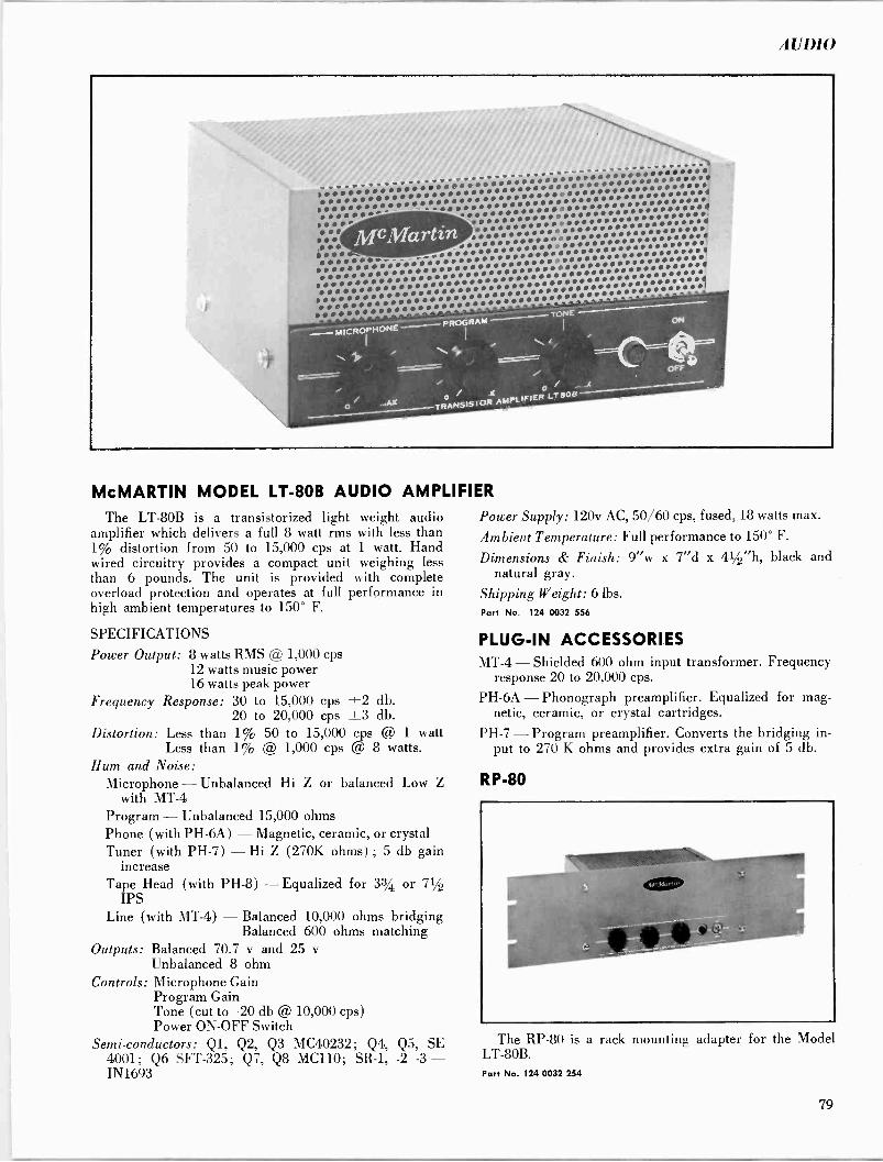
UI)11)
-i-t-.ifirrQíihaYIaa a s r.s w i i T pi i riIRt!rrr 1i ReilRRapeeil iiirrf:i1i4IIfIi1RaifellRapeRI1Ie 01109 i N i!rrR:iiiiepr11eia ipI-' efrifai:: iéir! ,r ** alilrrlrlpalrriee ri iiO! 1rif Oilieep11fel11ea ,..rr .r14e1f pjt/ieifa aliiii--- Ie1lealaefiaifl riiiiriRi1 141 i1Eiii®iii par iI/IisiieRi1 ssiiifi1i siái s b irIrsrer1r e1epiiiiiiriï#Ìïiiiij1 piisaiiI --7oNE
McMartin
McMARTIN MODEL LT -80B AUDIO AMPLIFIER
The LT -80B is a transistorized light weight audio amplifier which delivers a full 8 watt rms with less than 1% distortion from 50 to 15,000 cps at 1 watt. Hand wired circuitry provides a compact unit weighing less than 6 pounds. The unit is provided with complete overload protection and operates at full performance in high ambient temperatures to 150° F.
SPECIFICATIONS
Power Output: 8 watts RMS @ 1,000 cps 12 watts music power 16 watts peak power
Frequency Response: 30 to 15,000 cps ±2 db. 20 to 20,000 cps ±3 db.
Distortion: Less than 1% 50 to 15,000 cps @ 1 watt Less than 1% @ 1,000 cps @ 8 watts.
Hum and Noise: Microphone - Unbalanced Hi Z or balanced Low Z
with MT -4 Program - Unbalanced 15,000 ohms Phone (with PH -6A) - Magnetic, ceramic, or crystal Tuner (with PH -7) - Hi Z (270K ohms) ; 5 db gain
increase Tape Head (with PH -8) -Equalized for 33/4 or 71/2
IPS Line (with MT -4) - Balanced 10,000 ohms bridging
Balanced 600 ohms matching Outputs: Balanced 70.7 v and 25 v
Unbalanced 8 ohm Controls: Microphone Gain
Program Gain Tone (cut to -20 db @ 10,000 cps) Power ON-OFF Switch
Semi -conductors: Ql, Q2, Q3 MC40232; Q4, Q5, SE 4001; Q6 SFT-325; Q7, Q8 MC110; SR -1, -2 -3 - IN1693
Power Supply: 120v AC, 50/60 cps, fused, 18 watts max.
Ambient Temperature: Full performance to 150° F.
Dimensions & Finish: 9"w x 7"d x 41/2"h, black and natural gray.
Shipping Weight: 6 lbs. Part No. 124 0032 556
PLUG-IN ACCESSORIES MT -4 - Shielded 600 ohm input transformer. Frequency
response 20 to 20,000 cps.
PH -6A - Phonograph preamplifier. Equalized for mag- netic, ceramic, or crystal cartridges.
PH -7 - Program preamplifier. Converts the bridging in- put to 270 K ohms and provides extra gain of 5 db.
RP -80
The RP -80 is a rack mounting adapter for the Model LT -80B. Part No. 124 0032 254
79
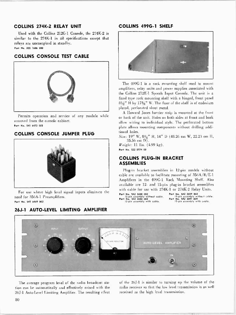
COLLINS 274K-2 RELAY UNIT
Used with the Collins 212G-1 Console, the 274K-2 is similar to the 274K-1 in all specifications except that relays are unenergized in standby. Part No. 522 1606 000
COLLINS CONSOLE TEST CABLE
Permits operation and service of any module while removed from the console cabinet. Part No. 541 6473 003
COLLINS CONSOLE JUMPER PLUG
For use where high level signal inputs eliminate the need for 356A-1 Preamplifiers. Port No. 541 6459 002
26J-1 AUTO -LEVEL LIMITING AMPLIFIER
COLLINS 499G-1 SHELF
The 499G-1 is a rack mounting shelf used to mount amplifiers, relay units and power supplies associated with the Collins 212E-1 Speech Input Console. The unit is a
fixed type rack mounting shelf with a hinged, front panel 81/2" H by 173/8" W. The floor of the shelf is of cadmium plated, perforated sheet metal.
A Howard Jones barrier strip is mounted at the front or back of the unit. Holes on both sides at front and back allow wiring to individual style. The perforated bottom plate allows mounting components without drilling addi- tional holes. Size: 19" W, 83/4" H, 14" D (48.26 cm W, 22.23 cm H,
35.56 cm D) .
Weight: 11 lbs. (4.99 kg) .
Part No. 522 0774 00
COLLINS PLUG-IN BRACKET ASSEMBLIES
Plug-in bracket assemblies in 12 -pin models without cable are available to facilitate mounting of 356A/B/E-1 Amplifiers in the 499G-1 Rack Mounting Shelf. Also
available are 12- and 15 -pin plug-in bracket assemblies with cable for use with 274K-1 or 274K-2 Relay Units. Part No. 542 3038 002
12 -pin assembly without cable. Part No. 542 3040 003
12 -pin assembly with cable.
Part No. 542 3039 002 15 -pin assembly without cable.
Part No. 542 3041 004 15 -pin assembly with cable.
The average program level of the radio broadcast sta-
tion can be automatically and effectively raised with the 26J-1 Auto -Level Limiting Amplifier. The resulting effect
of the 26J-1 is similar to turning up the volume of the
radio receiver so that the low level transmission is as well
received as the high level transmission.
80

AUDIO
Automatic fades between microphone and recorded music are also accomplished with the 26J-1. By setting the microphone level at a higher level than the turntable, the automatic fade occurs when the microphone is acti- vated. The higher microphone level automatically fades the music into the background and allows the speech to come through clearly. When the voice portion is absent, the 26J-1 restores the music level to normal. Since these fades are done automatically and electronically, they are far smoother and superior to manual fades.
The 26J-1 does not act as a peak limiting amplifier but functions on a low compression ratio which allows limit- ing action without noticeable effect on program material. With the slow action and compression ratio of the 26J-1, it is possible to limit up to 30 db without a noticeable effect other than bringing up the average listening level of the program material.
Working in conjunction with the Collins 26U-1 Peak Limiting Amplifier, the two units provide excellent peak limiting as well as average program limiting. The wide dynamic ranges used in most classical and popular music require considerable compression to allow low and high passages to be broadcast equally well.
The Collins 26U-1 Peak Limiting Amplifier, ideally located at the transmitter, protects over -modulation of
the transmitter, and the 26J-1 Auto -Level Limiting Am- plifier, located at the studio, boosts the average and low level program portions. Thus, these two units allow even the low-priced home and car receivers, which are not capable of reproducing wide dynamic ranges, to receive the entire broadcast as transmitted.
BLOCK DIAGRAM 26J -I
In those instances where there is not a good signal-to- noise ratio, such as old phonograph records and sports events with background noises, the 26J-1 can be operated as a straight amplifier. The limiting action may be dis- abled by turning off the gain reduction switch. Frequency Response: ±1 db, 50-15,000 cps. Gain: 25 db maximum as shipped. 41 db maximum, with
input pad changed from 22 db to 6 db. Input Impedance: 600 ohms unbalanced. Input Level: Adjustable, -26 dbm to +30 dbm. Easily
changed 22 db "T" pad in input circuit available. (0 dbm equals 1 mw across 600 ohms.)
Output Impedance: 600 ohms unbalanced. Output Level: Adjustable, -24 dbm to +30 dbm; +14
dbm nominal. Distortion: 1.5% maximum, 50-15,000 cps, with no com-
pression. 2% maximum distortion, 50-15,000 cps, at any level up to 30 db gain reduction, with threshold set for 3:1 compression ratio.
Output Noise: -50 dbm or less. (Threshold set for 3:1 ratio.)
Compression Ratio: 3:1 optimum; adjustable 1.6:1 to 5:1. Attack Time: 11 milliseconds, with switch set for dual
operation. 62 milliseconds, with switch set for aver- age operation.
Release Time: 0.9 seconds for 63% recovery, with switch set for dual operation. 5.2 seconds for 63% recovery, with switch set for average operation.
Power Source: 115 v or 230 v ac, 50-60 cps, single phase. Shipped wired for 115 v.
Size: 19" W, 51/2" H, 9" D (48.26 cm W, 13.97 cm H, 22.86 cm D) .
Weight: 16 lbs. (7.26 kg) .
Part No. 099 2814 00 No Part Number
FCC set of spare tubes (includes two silicon rectifiers).
21
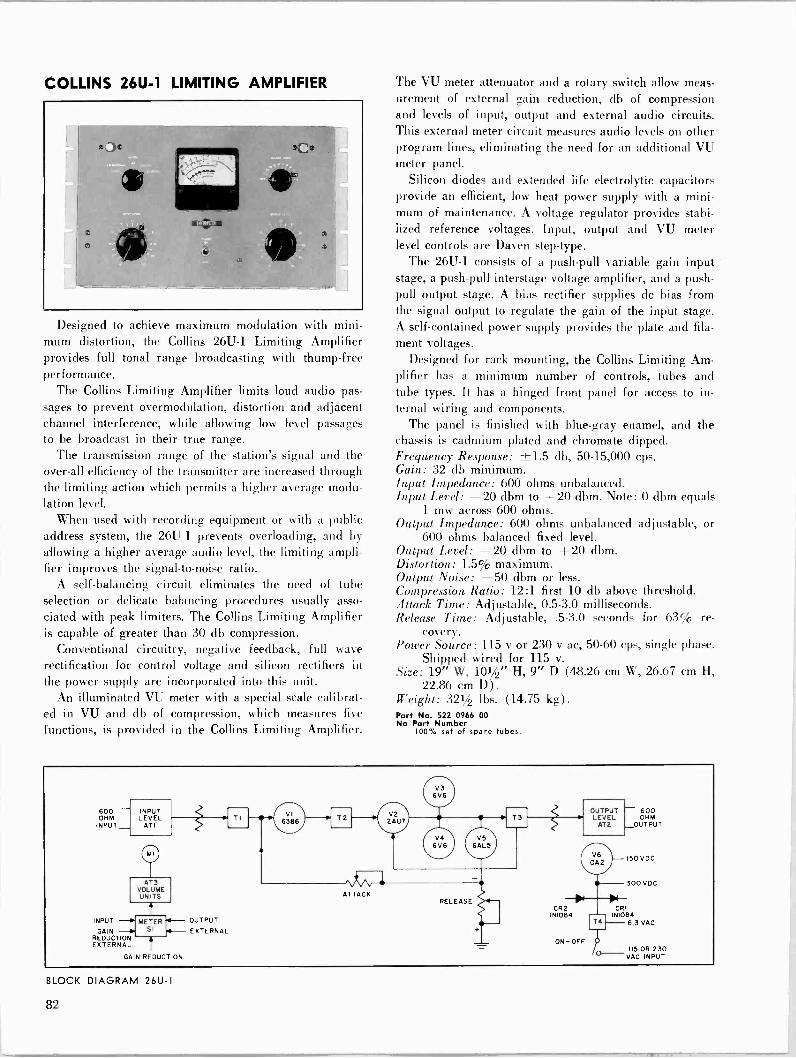
COLLINS 26U-1 LIMITING AMPLIFIER
Designed to achieve maximum modulation with mini mum distortion, the Collins 26U-1 Limiting Amplifier provides full tonal range broadcasting with thump -free performance.
The Collins Limiting Amplifier limits loud audio pas- sages to prevent overmodulation, distortion and adjacent channel interference, while allowing low level passages to be broadcast in their true range.
The transmission range of the station's signal and the over-all efficiency of the transmitter are increased through the limiting action which permits a higher average modu- lation level.
When used with recording equipment or with a public address system, the 26U-1 prevents overloading, and by allowing a higher average audio level, the limiting ampli- fier improves the signal-to-noise ratio.
A self -balancing circuit eliminates the need of tube selection or delicate balancing procedures usually asso- ciated with peak limiters. The Collins Limiting Amplifier is capable of greater than 30 db compression.
Conventional circuitry, negative feedback, full wave rectification for control voltage and silicon rectifiers in the power supply are incorporated into this unit.
An illuminated VU meter with a special scale calibrat- ed in VU and db of compression, which measures five
functions, is provided in the Collins Limiting Amplifier.
The VU meter attenuator and a rotary switch allow meas- urement of external gain reduction, db of compression and levels of input, output and external audio circuits. This external meter circuit measures audio levels on other program lines, eliminating the need for an additional VU meter panel.
Silicon diodes and extended life electrolytic capacitors provide an efficient, low heat power supply with a mini- mum of maintenance. A voltage regulator provides stabi- lized reference voltages. Input, output and VU meter level controls are Daven step -type.
The 26U-1 consists of a push-pull variable gain input stage, a push-pull interstage voltage amplifier, and a push- pull output stage. A bias rectifier supplies dc bias from the signal output to regulate the gain of the input stage. A self-contained power supply provides the plate and fila-
ment voltages. Designed for rack mounting, the Collins Limiting Am-
plifier has a minimum number of controls, tubes and tube types. It has a hinged front panel for access to in- ternal wiring and components.
The panel is finished with blue -gray enamel, and the chassis is cadmium plated and chromate dipped. Frequency Response: ±1.5 db, 50-15,000 cps. Gain: 32 db minimum. Input Impedance: 600 ohms unbalanced. Input Level: -20 dbm to +20 dbm. Note: 0 dbm equals
1 mw across 600 ohms. Output Impedance: 600 ohms unbalanced adjustable, or
600 ohms balanced fixed level. Output Level: -20 dbm to +20 dbm. Distortion: 1.5% maximum. Output Noise: -50 dbm or less. Compression Ratio: 12:1 first 10 db above threshold. Attack Time: Adjustable, 0.5-3.0 milliseconds. Release Time: Adjustable, .5-3.0 seconds for 63% re-
covery. Power Source: 115 v or 230 v ac, 50-60 cps, single phase.
Shipped wired for 115 v. Size: 19" W, 101/2" H, 9" D (48.26 cm W, 26.67 cm H,
22.86 cm D). Weight: 321/2 lbs. (14.75 kg) .
Part No. 522 0966 00 No Port Number
100°6 set of spare tubes.
600 OHM
INPUT
INPUT LEVEL
ATI
o AT3
VOLUME UNITS
INPUT
GAIN REDUCTION EXTERNAL
METER SI
GAIN REDUCTION
OUTPUT
EXTERNAL
TI VI 6386
OUTPUT 600 LEVEL OHM
AT2 OUTPUT
CRI INI084
6.3 VAC
I15 OR 230 VAC INPUT
BLOCK DIAGRAM 26U-1
t")
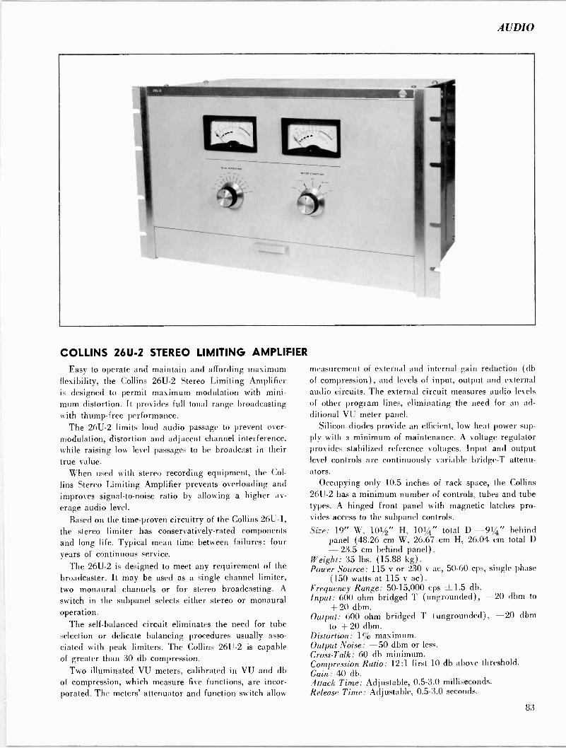
AUDIO
COLLINS 26U-2 STEREO LIMITING AMPLIFIER
Easy to operate and maintain and affording maximum flexibility, the Collins 26U-2 Stereo Limiting Amplifier is designed to permit maximum modulation with mini- mum distortion. It provides full tonal range broadcasting with thump -free performance.
The 26U-2 limits loud audio passage to prevent over - modulation, distortion and adjacent channel interference, while raising low level passages to be broadcast in their true value.
When used with stereo recording equipment, the Col-
lins Stereo Limiting Amplifier prevents overloading and improves signal-to-noise ratio by allowing a higher av-
erage audio level.
Based on the time -proven circuitry of the Collins 26U-1, the stereo limiter has conservatively -rated components and long life. Typical mean time between failures: four years of continuous service.
The 26U-2 is designed to meet any requirement of the broadcaster. It may be used as a single channel limiter, two monaural channels or for stereo broadcasting. A
switch in the subpanel selects either stereo or monaural operation.
The self -balanced circuit eliminates the need for tube selection or delicate balancing procedures usually asso-
ciated with peak limiters. The Collins 26U-2 is capable of greater than 30 db compression.
Two illuminated VU meters, calibrated in VU and db of compression, which measure five functions, are incor- porated. The meters' attenuator and function switch allow
measurement of external and internal gain reduction (db of compression), and levels of input, output and external audio circuits. The external circuit measures audio levels of other program lines, eliminating the need for an ad- ditional VU meter panel.
Silicon diodes provide an efficient, low heat power sup- ply with a minimum of maintenance. A voltage regulator provides stabilized reference voltages. Input and output level controls are continuously variable bridge -T attenu- ators.
Occupying only 10.5 inches of rack space, the Collins 26U-2 has a minimum number of controls, tubes and tube types. A hinged front panel with magnetic latches pro- vides access to the subpanel controls.
Size: 19" W, 101/2" H, 101/4" total D - 91/4" behind panel (48.26 cm W, 26.67 cm H, 26.04 cm total D - 23.5 cm behind panel) .
Weight: 35 lbs. (15.88 kg) .
Power Source: 115 v or 230 v ac, 50-60 cps, single phase (150 watts at 115 v ac) .
Frequency Range: 50-15,000 cps ±1.5 db. Input: 600 ohm bridged T (ungrounded), -20 dbm to
+ 20 dbm. Output: 600 ohm bridged T (ungrounded), -20 dbm
to +20 dbm. Distortion: 1% maximum. Output Noise: -50 dbm or less. Cross -Talk: 60 db minimum. Compression Ratio: 12:1 first 10 db above threshold. Gain: 40 db. Attack Time: Adjustable, 0.5-3.0 milliseconds. Release Time: Adjustable, 0.5-3.0 seconds.
83
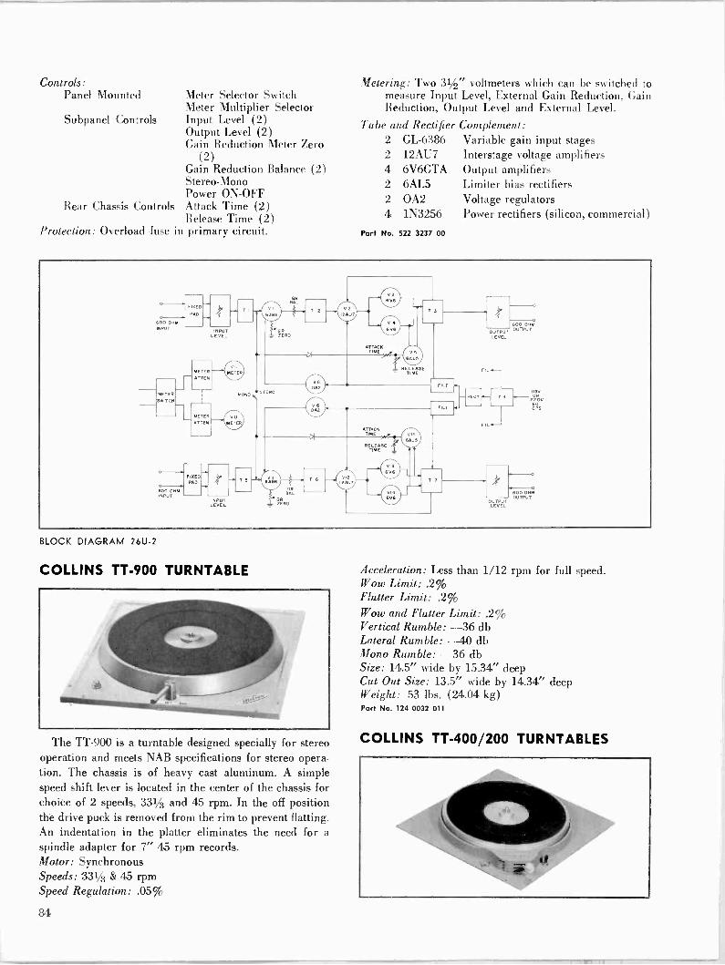
Controls: Panel Mounted
Subpanel Controls
Rear Chassis Controls
Meter Selector Switch Meter Multiplier Selector Input Level (2) Output Level (2) Gain Reduction Meter Zero
(2) Gain Reduction Balance (2) Stereo -Mono Power ON-OFF Attack Time (2) Release Time (2)
Protection: Overload fuse in primary circuit.
BLOCK DIAGRAM 26U-2
COLLINS TT -900 TURNTABLE
The TT -900 is a turntable designed specially for stereo operation and meets NAB specifications for stereo opera- tion. The chassis is of heavy cast aluminum. A simple speed shift lever is located in the center of the chassis for choice of 2 speeds, 331/3 and 45 rpm. In the off position the drive puck is removed from the rim to prevent flatting. An indentation in the platter eliminates the need for a
spindle adapter for 7" 45 rpm records. Motor: Synchronous Speeds: 331/3 & 45 rpm Speed Regulation: .05%
Metering: Two 31/2" voltmeters which can be switched to measure Input Level, External Gain Reduction, Gain Reduction, Output Level and External Level.
Tube and Rectifier Complement: 2 GL -6386 Variable gain input stages 2 12AU7 Interstage voltage amplifiers 4 6V6GTA Output amplifiers 2 6AL5 Limiter bias rectifiers 2 OA2 Voltage regulators 4 1N3256 Power rectifiers (silicon, commercial)
Part No. 522 3237 00
Acceleration: Less than 1/12 rpm for full speed. Wow Limit: .2% Flutter Limit: .2% Wow and Flutter Limit: .2% Vertical Rumble: -36 db Lateral Rumble: -40 db Mono Rumble: -36 db Size: 14.5" wide by 15.34" deep Cut Out Size: 13.5" wide by 14.34" deep Weight: 53 lbs. (24.04 kg) Part No. 124 0032 011
COLLINS TT -400/200 TURNTABLES
84
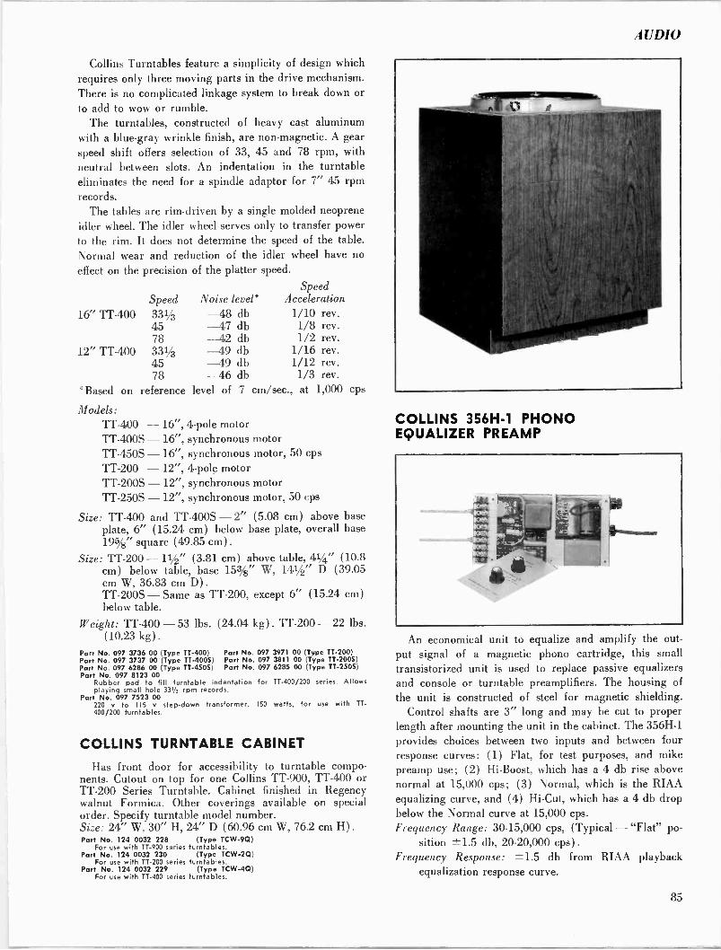
AUDIO
Collins Turntables feature a simplicity of design which requires only three moving parts in the drive mechanism. There is no complicated linkage system to break down or
to add to wow or rumble. The turntables, constructed of heavy cast aluminum
with a blue -gray wrinkle finish, are non-magnetic. A gear speed shift offers selection of 33, 45 and 78 rpm, with neutral between slots. An indentation in the turntable eliminates the need for a spindle adaptor for 7" 45 rpm records.
The tables are rim -driven by a single molded neoprene idler wheel. The idler wheel serves only to transfer power to the rim. It does not determine the speed of the table.
Normal wear and reduction of the idler wheel have no
effect on the precision of the platter speed.
Speed Speed Noise level* Acceleration
16" TT -400 3313 -48 db 1/10 rev. 45 -47 db 1/8 rev. 78 -42 db 1/2 rev.
12" TT -400 331/3 -49 db 1/16 rev. 45 -49 db 1/12 rev. 78 -46 db 1/3 rev.
*Based on reference level of 7 cm/sec., at 1,000 cps
Models: TT -400 - TT -400S - TT -450S - TT -200 - TT -200S TT -250S -
16", 4 -pole motor 16", synchronous motor 16", synchronous motor, 50 cps
12", 4 -pole motor - 12", synchronous motor 12", synchronous motor, 50 cps
Size: TT -400 and TT -4005 - 2" (5.08 cm) above base plate, 6" (15.24 cm) below base plate, overall base 195/8" square (49.85 cm) .
Size: TT -200 - 11/2" (3.81 cm) above table, 41/4" (10.8 cm) below table, base 153/8" W, 141/2" D (39.05 cm W, 36.83 cm D) . TT -200S - Same as TT -200, except 6" (15.24 cm) below table.
Weight: TT -400 - 53 lbs. (24.04 kg) . TT -200 - 22 lbs. (10.23 kg).
Part No. 097 3736 00 (Type TT -400) Part No 097 3971 00 (Type TT -200) Part No. 097 3737 00 (Type TT -400S) Part No 097 3811 00 (Type TT -200S) Part No. 097 6286 00 (Type TT -450S) Part No 097 6285 00 (Type TT -250S) Part No. 097 8123 00
Rubber pad to fill turntable indentation for TT -400/200 series. Allows playing small hole 331/3 rpm records.
Part No. 097 7523 00 220 y to IIS y step-down transformer. 150
400/200 turntables. watts, for use with TT-
COLLINS TURNTABLE CABINET
Has front door for accessibility to turntable compo- nents. Cutout on top for one Collins TT -900, TT -400 or TT -200 Series Turntable. Cabinet finished in Regency walnut Formica. Other coverings available on special order. Specify turntable model number. Size: 24" W, 30" H, 24" D (60.96 cm W, 76.2 cm H). Part No. 124 0032 228 (Type TCW-9Q)
For use with TT -900 series turntables. Part No. 124 0032 230 (Type TCW-2Q)
For use with TT -200 series turntables. Part No. 124 0032 229 (Type TCW-4Q)
For use with TT -400 series turntables.
COLLINS 356H-1 PHONO EQUALIZER PREAMP
An economical unit to equalize and amplify the out-
put signal of a magnetic phono cartridge, this small transistorized unit is used to replace passive equalizers and console or turntable preamplifiers. The housing of the unit is constructed of steel for magnetic shielding.
Control shafts are 3" long and may be cut to proper length after mounting the unit in the cabinet. The 356H-1 provides choices between two inputs and between four response curves: (1) Flat, for test purposes, and mike preamp use; (2) Hi -Boost, which has a 4 db rise above normal at 15,000 cps; (3) Normal, which is the RIAA equalizing curve, and (4) Hi -Cut, which has a 4 db drop below the Normal curve at 15,000 cps. Frequency Range: 30-15,000 cps, (Typical - "Flat" po-
sition -±-1.5 db, 20-20,000 cps) .
Frequency Response: ±1.5 db from RIAA playback equalization response curve.
85
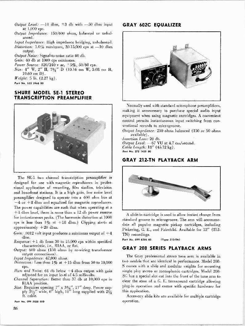
Output Level: -10 dbm, ±3 db with -50 dbm input at 1,000 cps.
Output Impedance: 150/600 ohms, balanced or unbal- anced.
Input Impedance: High impedance bridging, unbalanced. Distortion: 1.0% maximum, 30-15,000 cps at -10 dbm
output. Output Noise: Signal-to-noise ratio 60 db. Gain: 40 db at 1000 cps minimum. Power Source: 120/240 v ac, ±5%0, 50/60 cps. Size: 4" W, 2" H, 73/4" D (10.16 cm W, 5.08 cm H,
19.60 cm D). Weight: 5 lb. (2.27 kg) .
Part No. 522 2468 00
SHURE MODEL SE -1 STEREO TRANSCRIPTION PREAMPLIFIER
The SE -1 two channel transcription preamplifier is designed for use with magnetic reproducers in profes- sional application of recording, film studios, television and broadcast stations. It is a high gain, low noise level preamplifier designed to operate into a 600 ohm bus at +4 or +8 dbm and equalized for magnetic reproducers. The power capabilities are such that when operating at a +4 dbm level, there is more than a 12 db power reserve for instantaneous peaks. (The harmonic distortion at 1000 cps is less than 1% at +18 dbm.) Clipping starts at approximately + 20 dbm.
Gain: .0012 volt input produces a minimum output of +4 dbm.
Response: +1 db from 30 to 15,000 cps within specified characteristic, i.e., RIAA, or flat.
Output: 600 ohms (150 ohms by re -wiring transformer output connections) .
Input Impedence: 47,000 ohms. Distortion: Less than 1% at +15 dbm from 50 to 10,000
cps. Hum and Noise: 64 db below +4 dbm output with gain
adjusted for an input level of 4.5 millivolts. Channel Separation: Better than 37 db at 10,000 cps in
RIAA position. Size: Requires opening 7" x 33/8", 11" deep. Power sup-
ply 31/2" wide, 6" high, 11" long supplied with 21/2 ft. cable.
Part No. 099 3020 000
GRAY 602C EQUALIZER
Normally used with standard microphone preamplifiers, making it unnecessary to purchase special audio input equipment when using magnetic cartridges. A convenient control permits instantaneous input switching from con- ventional records to microgroove. Output Impedance: 250 ohms balanced (150 or 50 ohms
available). Insertion Loss: 20 db. Output Level: -67 VU at 4.7 cm/second. Cable Length: 18" (45.72 kg) .
Part No. 272 1438 00
GRAY 212 -TN PLAYBACK ARM
A slide -in cartridge is used to allow instant change from standard groove to microgroove. The arm will accommo- date all popular magnetic pickup cartridges, including Pickering, G. E., and Fairchild. Available for 12" (212 - TN) recordings. Part No. 099 0386 00 (Type 212 -TN)
GRAY 208 SERIES PLAYBACK ARMS
The Gray professional stereo tone arm is available in two models that are identical in performance. Model 208- S comes with a slide and modular weights for mounting single play stereo or monophonic cartridges. Model 208 - SG has a special slot cut into the front of the tone arm to clear the stem of a G. E. turnaround cartridge allowing plug-in operation and comes with specific hardware for this application.
Accessory slide kits are available for multiple cartridge operation.
86
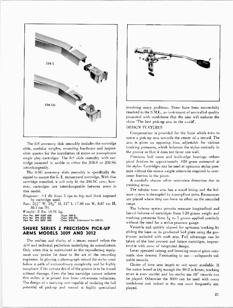
The 8-S accessory slide assembly includes the cartridge slide, modular weights, mounting hardware and impres- sible spacers for the installation of stereo or monophonic single play cartridges. The 8-S slide assembly with car- tridge mounted is usable in either the 208-S or 208 -SG
interchangeably. The 8 -SG accessory slide assembly is specifically de-
signed to mount the G. E. turnaround cartridge. With this cartridge installed, it will only fit the 208 -SC arm; how- ever, cartridges are interchangeable between arms in this model. Response: ±1 db from 5 cps to top end limit imposed
by cartridge used. Size: 2f " W, 25/8" H, 15" L (7.46 cm W, 6.67 cm H,
38.1 cm D) .
Weight: 2 lbs. (0.91 kg. Part No. 099 0387 000 (Type 208-S) Part No. 099 0164 000 (Type 208 -SG) Part No. 099 0837 000 (Type 8 -SG) Slidemount for 208-5G.
SHURE SERIES 2 PRECISION PICK-UP ARMS MODELS 3009 AND 3012
The realism and clarity of a stereo record reflect the skill and technical perfection underlying its manufacture. Only when this is maintained in the reproducing equip- ment can justice be done to the art of the recording engineers. In playing a phonograph record the stylus must follow a path of extraordinary complexity and be highly compliant if the minute detail of the groove is to be traced without damage. Even the best cartridge cannot achieve this unless it is poised free from extraneous influences. The design of a carrying arm capable of realizing the full potential of pick-up and record is highly specialized
involving many problems. These have been successfully resolved in the S.M.E., an instrument of unrivalled quality presented with confidence that the user will endorse the claim 'The best pick-up arm in the world'.
DESIGN FEATURES
Compensation is provided for the force which tries to move a pick-up arm towards the center of a record. The arm is given an opposing bias, adjustable for various tracking pressures, which balances the stylus centrally in the groove so that it does not favor one wall.
Precision ball races and knife-edge bearings reduce pivot friction to approximately .020 gram measured at the stylus. Cartridges can be used at optimum stylus pres- sure without the excess weight otherwise required to over- come friction in the pivots.
A carefully chosen offset minimizes distortion due to tracking error.
The tubular tone arm has a wood lining and the bal- ance system is decoupled by a compliant joint. Resonances are placed where they can have no effect on the recorded range.
The balance system permits accurate longitudinal and lateral balance of cartridges from 5-20 grams weight and tracking pressures from 1/4 to 5 grams applied precisely without the need for a stylus pressure gauge.
Versatile and quickly aligned for optimum tracking by sliding the base on its graduated bed plate using the pro- tractor included with each arm. Full advantage can be taken of the best present and future cartridges, imprac- ticable with arms of integrated design.
Lever operated raising and lowering control gives auto- matic slow descent. Fascinating to use - safeguards val- uable records.
Choice of tone arm length to suit space available. If the motor board is big enough the 3012 is better, tracking error is even smaller and for studio use 16" records can be played. Otherwise the 3009 can be used with every confidence and indeed is the one most frequently em- ployed.
87
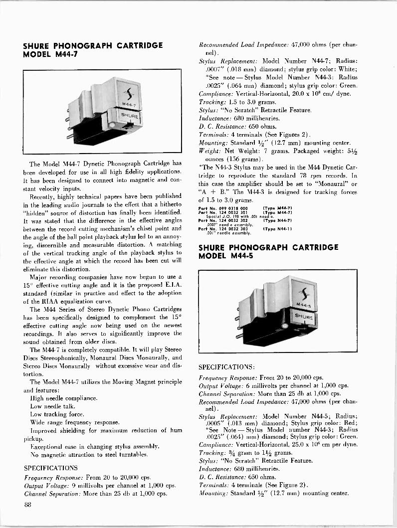
SHURE PHONOGRAPH CARTRIDGE MODEL M44-7
The Model M44-7 Dynetic Phonograph Cartridge has
been developed for use in all high fidelity applications. It has been designed to connect into magnetic and con-
stant velocity inputs. Recently, highly technical papers have been published
in the leading audio journals to the effect that a hitherto "hidden" source of distortion has finally been identified. It was stated that the difference in the effective angles
between the record cutting mechanism's chisel point and
the angle of the ball point playback stylus led to an annoy- ing, discernible and measurable distortion. A matching of the vertical tracking angle of the playback stylus to
the effective angle at which the record has been cut will
eliminate this distortion. Major recording companies have now begun to use a
15° effective cutting angle and it is the proposed E.I.A.
standard (similar in practice and effect to the adoption of the RIAA equalization curve.
The M44 Series of Stereo Dynetic Phono Cartridges has been specifically designed to complement the 15°
effective cutting angle now being used on the newest recordings. It also serves to significantly improve the sound obtained from older discs.
The M44-7 is completely compatible. It will play Stereo Discs Stereophonically, Monaural Discs Monaurally, and Stereo Discs Monaurally without excessive wear and dis-
tortion. The Model M44-7 utilizes the Moving Magnet principle
and features: High needle compliance. Low needle talk. Low tracking force. Wide range frequency response. Improved shielding for maximum reduction of hum
pickup. Exceptional ease in changing stylus assembly. No magnetic attraction to steel turntables.
SPECIFICATIONS Frequency Response: From 20 to 20,000 cps.
Output Voltage: 9 millivolts per channel at 1,000 cps. Channel Separation: More than 25 db at 1,000 cps.
Recommended Load Impedance: 47,000 ohms (per chan- nel) .
Stylus Replacement: Model Number N44-7; Radius: .0007" (.018 mm) diamond; stylus grip color: White; *See note - Stylus Model Number N44-3: Radius .0025" (.064 mm) diamond; stylus grip color: Green.
Compliance: Vertical -Horizontal, 20.0 x 106 cm/ dyne. Tracking: 1.5 to 3.0 grams. Stylus: "No Scratch" Retractile Feature. Inductance: 680 millihenries. D. C. Resistance: 650 ohms. Terminals: 4 terminals (See Figures 2). Mounting: Standard 1/2" (12.7 mm) mounting center. Weight: Net Weight: 7 grams. Packaged weight: 51/2
ounces (156 grams) .
*The N44-3 Stylus may be used in the M44 Dynetic Car- tridge to reproduce the standard 78 rpm records. In this case the amplifier should be set to "Monaural" or "A + B." The M44-3 is designed for tracking forces of 1.5 to 3.0 grams. Part No. 099 0318 000 (Type M44.7) Part No. 124 0032 301 (Type M44-7)
Special J.O. 198 with .001 needle. Part No. 124 0032 302 (Type N44-7)
.0007" needle assembly. Part No. 124 0032 303 (Type N44.1)
.001" needle assembly.
SHURE PHONOGRAPH CARTRIDGE MODEL M44-5
SPECIFICATIONS:
Frequency Response: From 20 to 20,000 cps.
Output Voltage: 6 millivolts per channel at 1,000 cps. Channel Separation: More than 25 db at 1,000 cps.
Recommended Load Impedance: 47,000 ohms (per chan- nel) .
Stylus Replacement: Model Number N44-5; Radius; .0005" (.013 mm) diamond; Stylus grip color: Red; *See Note - Stylus Model number N44-3; Radius .0025" (.064) mm) diamond; Stylus grip color: Green.
Compliance: Vertical -Horizontal, 25.0 x 106 cm per dyne. Tracking: 3/4 gram to 11/2 grams. Stylus: "No Scratch" Retractile Feature. Inductance: 680 millihenries. D. C. Resistance: 650 ohms. Terminals: 4 terminals (See Figure 2). Mounting: Standard 1/2" (12.7 mm) mounting center.
88

TAPE AUDIO
Weight: Net Weight: 7 grams. Packaged weight: 51/2 ounces (156 grams).
*The N44-3 Stylus may be used in the M44 Dynetic Car- tridge to reproduce the standard 78 rpm records. In this case, the amplifier should be set to "Monaural" or "A + B." The N44-3 is designed for tracking forces of 1.5 to 3.0 grams.
SHURE PHONOGRAPH CARTRIDGE MODELS M5D AND M6S
The M5 and M6 Professional Dynetic Cartridges have been developed specifically for use in custom high fidelity sets, record changers, and transcription arms. These car- tridges have been designed to connect into magnetic and constant velocity inputs.
This new electromagnetic transducer utilizes the same Dynetic principle employed in the Studio Dynetic Car- tridge and tone arm assembly. This new electro -mechani- cal principle uses a moving magnet which provides extreme linearity and freedom from distortion. Since the magnet turns on its vertical axis, it is possible to place the needle tip at the end of a light metallic beam, provid- ing very low needle point mass. The stylus assembly is held in a durable elastomer composition which provides high needle compliance. Vertical compliance at the needle tip is excellent. Because of these factors, needle talk is practically nonexistent. Other important features are:
1. Needle replacement is exceptionally simple and fast. No tools are required.
2. Magnetic induction from external hum fields is re- duced to a minimum.
3. No magnetic attraction to steel turntables.
SPECIFICATIONS - MODEL M5D Use: Microgroove, 331/3 - 45 R.P.M. Stylus Radius: 1 Mil (0.025 mm) Diamond. Stylus No.: N5D. Stylus Color Coding: Black Dot.
SPECIFICATIONS - MODEL M6S Use: Standard 78 R.P.M. Stylus Radius: 2.7 Mil (0.069 mm) Synthesized Sapphire. Stylus No.: N6S. Stylus Color Coding: Yellow Dot. Response Frequency Characteristic: From 20 to 20,000
cps (See Fig. 1) designed to ideally meet the exacting requirements of typical high fidelity reproduction.
Output Voltage: Output at 1000 cycles 21 millivolts for 10 centimeters per second.
Recommended Load Impedance: 27,000 ohms. Higher values will produce a slight increase in high frequency response.
Compliance: 3.0 x 10⁶ centimeters per dyne. Tracking Force: 3 to 6 grams. Inductance: 350 millihenries. D. C. Resistance: 440 ohms. Weight: .44 ounces (12.4 g.) .
Packaged Weight: 3.3 ounces (95 g.).
SHURE PLAYBACK ARMS
Accepts stereo and monophonic cartridges. Arm fea- tures precision ball bearings at all pivot points, plug-in head with positive alignment lock and variable adjust- ment. Supplied with arm rest, mounting template, mount- ing hardware and 4 -foot cable assembly. Size and Weight: 12" arm (M232) , 12}1" L, 1 lb.
(0.45 kg) ; 16" arm (M236), 141/2" L, 11/8 lbs. (0.48 kg).
Part No. 097 8118 00 (Type M232) Part No. 097 8122 00 (Type M236)
REK-O-KUT PLAYBACK ARMS
Tubular arm body with die cast aluminum cartridge shell. Four -conductor lead accommodates all 3- and 4 -wire stereo cartridges. Does not include but uses all standard cartridges. Available for either 16" (S-260) or 12"(S-320) recordings. Part No. 099 0242 000 (Type S-260) less balance weight. Part No. 099 0241 000 (Type S-320) with balance weight. Part No. 124 0032 094 Balance weight for S-260
89
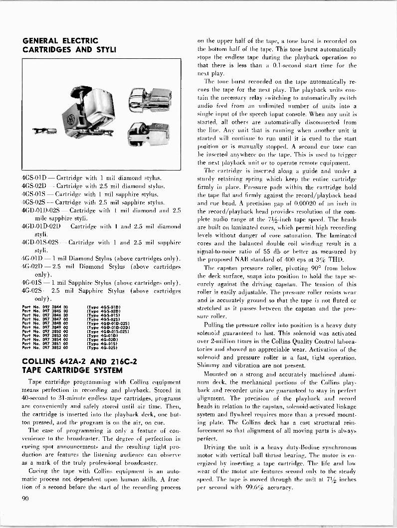
GENERAL ELECTRIC CARTRIDGES AND STYLI
4GS-01D - Cartridge with 1 mil diamond stylus. 4GS-02D - Cartridge with 2.5 mil diamond stylus. 4GS-01S - Cartridge with 1 mil sapphire stylus. 4GS-02S - Cartridge with 2.5 mil sapphire stylus. 4GD-01D-02S - Cartridge with 1 mil diamond and 2.5
mile sapphire styli. 4GD-01D-02D - Cartridge with 1 and 2.5 mil diamond
styli. 4GD-01S-02S - Cartridge with 1 and 2.5 mil sapphire
styli. 4G -01D -1 mil Diamond Stylus (above cartridges only) .
4G -02D - 2.5 mil Diamond Stylus (above cartridges only).
4G -01S - 1 mil Sapphire Stylus (above cartridges only) .
4G -02S - 2.5 only).
mil Sapphire Stylus (above cartridges
Part No. 097 3844 00 (Type 4GS-01D) Part No. 097 3845 00 (Type 4GS-02D) Part No. 097 3846 00 (Type 4GS-01S) Pari No. 097 3847 00 (Type 4GS-02S) Part No. 097 3848 00 (Type 4GD-01D-02S) Part No. 097 3849 00 (Type 4GD-01D-02D) Part No. 097 3850 00 (Type 4GD-01S-02S) Part No. 097 3853 00 (Type 4G -01D) Part No. 097 3854 00 (Type 4G-020) Part No. 097 3851 00 (Type 4G -01S) Part No. 097 3852 00 (Type 4G -02S)
COLLINS 642A-2 AND 216C-2 TAPE CARTRIDGE SYSTEM
Tape cartridge programming with Collins equipment means perfection in recording and playback. Stored in 40 -second to 31 -minute endless tape cartridges, programs are conveniently and safely stored until air time. Then, the cartridge is inserted into the playback deck, one but- ton pressed, and the program is on the air, on cue.
The ease of programming is only a feature of con- venience to the broadcaster. The degree of perfection in cueing spot announcements and the resulting tight pro- duction are features the listening audience can observe as a mark of the truly professional broadcaster.
Cueing the tape with Collins equipment is an auto- matic process not dependent upon human skills. A frac- tion of a second before the start of the recording process
on the upper half of the tape, a tone burst is recorded on the bottom half of the tape. This tone burst automatically stops the endless tape during the playback operation so that there is less than a 0.1 -second start time for the next play.
The tone burst recorded on the tape automatically re - cues the tape for the next play. The playback units con- tain the necessary relay switching to automatically switch audio feed from an unlimited number of units into a single input of the speech input console. When any unit is started, all others are automatically disconnected from the line. Any unit that is running when another unit is started will continue' to run until it is cued to the start position or is manually stopped. A second cue tone can be inserted anywhere on the tape. This is used to trigger the next playback unit or to operate remote equipment.
The cartridge is inserted along a guide and under a sturdy retaining spring which keep the entire cartridge firmly in place. Pressure pads within the cartridge hold the tape flat and firmly against the record/playback head and cue head. A precision gap of 0.00020 of an inch in the record/playback head provides resolution of the com- plete audio range at the 71/2 -inch tape speed. The heads are built on laminated cores, which permit high recording levels without danger of core saturation. The laminated cores and the balanced double coil winding result in a signal-to-noise ratio of 55 db or better as measured by the proposed NAB standard of 400 cps at 3% THD.
The capstan pressure roller, pivoting 90° from below the deck surface, snaps into position to hold the tape se-
curely against the driving capstan. The tension of this roller is easily adjustable. The pressure roller resists wear and is accurately ground so that the tape is not fluted or stretched as it passes between the capstan and the pres- sure roller.
Pulling the pressure roller into position is a heavy duty solenoid guaranteed to last. This solenoid was activated over 2 -million times in the Collins Quality Control labora- tories and showed no appreciable wear. Activation of the solenoid and pressure roller is a fast, tight operation. Shimmy and vibration are not present.
Mounted on a strong and accurately machined alumi- num deck, the mechanical portions of the Collins play- back and recorder units are guaranteed to stay in perfect alignment. The precision of the playback and record heads in relation to the capstan, solenoid -activated linkage system and flywheel requires more than a pressed mount- ing plate. The Collins deck has a cast structural rein- forcement so that alignment of all moving parts is always perfect.
Driving the unit is a heavy duty -Bodine synchronous motor with vertical ball thrust bearing. The motor is en- ergized by inserting a tape cartridge. The life and low wear of the motor are features second only to the steady speed. The tape is moved through the unit at 71/2 inches per second with 99.6% accuracy.
90
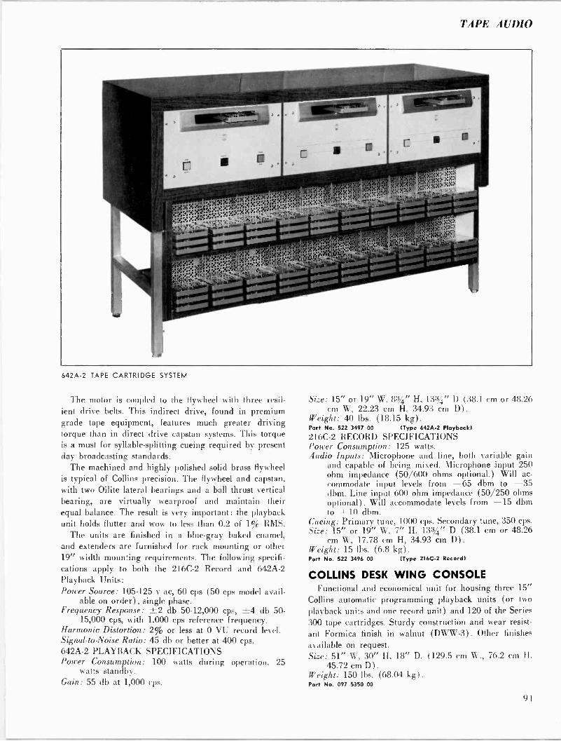
TAPE AUDIO
642A-2 TAPE CARTRIDGE SYSTEM
The motor is coupled to the flywheel with three resil- ient drive belts. This indirect drive, found in premium grade tape equipment, features much greater driving torque than in direct drive capstan systems. This torque is a must for syllable -splitting cueing required by present day broadcasting standards.
The machined and highly polished solid brass flywheel is typical of Collins precision. The flywheel and capstan, with two Oilite lateral bearings and a ball thrust vertical bearing, are virtually wearproof and maintain their equal balance. The result is very important: the playback unit holds flutter and wow to less than 0.2 of 1% RMS.
The units are finished in a blue -gray baked enamel, and extenders are furnished for rack mounting or other 19" width mounting requirements. The following specifi- cations apply to both the 216C-2 Record and 642A-2 Playback Units: Power Source: 105-125 v ac, 60 cps (50 cps model avail-
able on order), single phase. Frequency Response: ±2 db 50-12,000 cps, ±4 db 50-
15,000 cps, with 1,000 cps reference frequency. Harmonic Distortion: 2% or less at 0 VU record level. Signal -to -Noise Ratio: 45 db or better at 400 cps. 642A-2 PLAYBACK SPECIFICATIONS Power Consumption: 100 watts during operation, 25
watts standby. Gain: 55 db at 1,000 cps.
Size: 15" or 19" W, 8%" H, 133/1" D (38.1 cm or 48.26 cm W, 22.23 cm H, 34.93 cm D).
Weight: 40 lbs. (18.15 kg) .
Port No. 522 3497 00 (Type 642A-2 Playback)
216C-2 RECORD SPECIFICATIONS Power Consumption: 125 watts. Audio Inputs: Microphone and line, both variable gain
and capable of being mixed. Microphone input 250 ohm impedance (50/600 ohms optional.) Will ac- commodate input levels from -65 dbm to -35 dbm. Line input 600 ohm impedance (50/250 ohms optional). Will accommodate levels from -15 dbm to + 10 dbm.
Cueing: Primary tune, 1000 cps. Secondary tune, 350 cps. Size: 15" or 19" W, 7" H, 133/4" D (38.1 cm or 48.26
cm W, 17.78 cm H, 34.93 cm D) .
Weight: 15 lbs. (6.8 kg) .
Part No. 522 3496 00 (Type 216C-2 Record)
COLLINS DESK WING CONSOLE Functional and economical unit for housing three 15"
Collins automatic programming playback units (or two
playback units and one record unit) and 120 of the Series 300 tape cartridges. Sturdy construction and wear resist-
ant Formica finish in walnut (DWW-3). Other finishes available on request. Size: 51" W, 30" H, 18" D. (129.5 cm W., 76.2 cm H,
45.72 cm D). Weight: 150 lbs. (68.04 kg) .
Part No. 097 5350 00
91
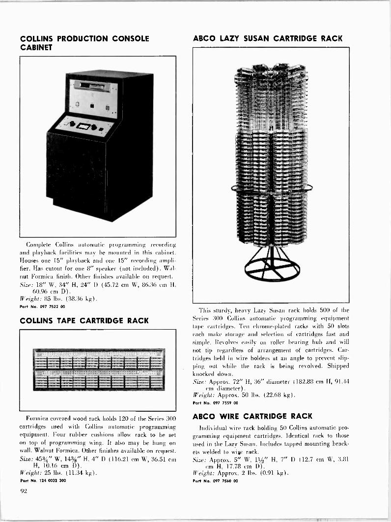
COLLINS PRODUCTION CONSOLE CABINET
Complete Collins automatic programming recording and playback facilities may be mounted in this cabinet. Houses one 15" playback and one 15" recording ampli- fier. Has cutout for one 8" speaker (not included). Wal- nut Formica finish. Other finishes available on request. Size: 18" W, 34" H, 24" D (45.72 cm W, 86.36 cm H,
60.96 cm D). Weight: 85 lbs. (38.36 kg). Port No. 097 7522 00
COLLINS TAPE CARTRIDGE RACK
Formica covered wood rack holds 120 of the Series 300 cartridges used with Collins automatic programming equipment. Four rubber cushions allow rack to be set on top of programming wing. It also may be hung on wall. Walnut Formica. Other finishes available on request. Size: 453/4" W, 14%" H, 4" D (116.21 cm W, 36.51 cm
H, 10.16 cm D). Weight: 25 lbs. (11.34 kg). Port No. 124 0032 300
ABCO LAZY SUSAN CARTRIDGE RACK
This sturdy, heavy Lazy Susan rack holds 500 of the Series 300 Collins automatic programming equipment tape cartridges. Ten chrome -plated racks with 50 slots each make storage and selection of cartridges fast and simple. Revolves easily on roller bearing hub and will
not tip regardless of arrangement of cartridges. Car- tridges held in wire holders at an angle to prevent slip- ping out while the rack is being revolved. Shipped knocked down. Size: Approx. 72" H, 36" diameter (182.88 cm H, 91.44
cm diameter). Weight: Approx. 50 lbs. (22.68 kg). Part No. 097 7559 00
ABCO WIRE CARTRIDGE RACK
Individual wire rack holding 50 Collins automatic pro- gramming equipment cartridges. Identical rack to those
used in the Lazy Susan. Includes tapped mounting brack- ets welded to wieg rack. Size: Approx. 5" W, 11/2" H, 7" D (12.7 cm W, 3.81
cm H, 17.78 cm D) .
Weight: Approx. 2 lbs. (0.91 kg). Port No. 097 7560 00
92
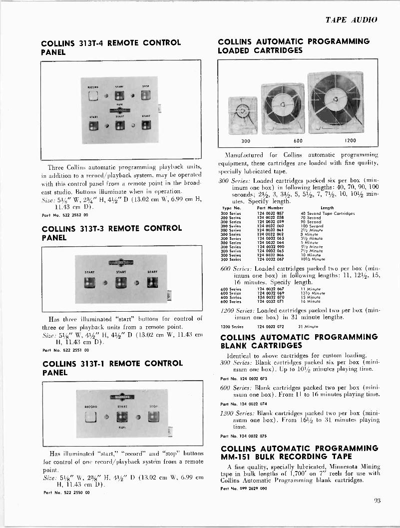
TAPE AUDIO
COLLINS 313T-4 REMOTE CONTROL PANEL
Three Collins automatic programming playback units,
in addition to a record, /playback system, may be operated
with this control panel from a remote point in the broad-
cast studio. Buttons illuminate when in operation. Size: 51/8" W,23/,t"H,41/2"D (13.02 cm W, 6.99 cm H,
11.43 cm D). Par+ No. 522 2552 00
COLLINS 313T-3 REMOTE CONTROL PANEL
Has three illuminated "start" buttons for control of
three or less playback units from a remote point. Size: 51/8" W, 41/2" H, 41/2" D (13.02 cm W, 11.43 cm
H, 1L43 cm D) .
Part No. 522 2551 00
COLLINS 313T-1 REMOTE CONTROL PANEL
RECORD
-5
orzio START
w RUN
Has illuminated "start," "record" and "stop" buttons for control of one record/playback systéYn from a remote point. Size: 51/8" W, 2%" H, 41/2" D (13.02 cm W, 6.99 cm
H, 11.43 cm D) . Part No. 522 2550 00
COLLINS AUTOMATIC PROGRAMMING LOADED CARTRIDGES
Manufactured for Collins automatic programming equipment, these cartridges are loaded with fine quality, specially lubricated tape.
300 Series: Loaded cartridges packed six per box (min- imum one box) in following lengths: 40, 70, 90, 100 seconds; 21/2, 3, 31/2, 5, 51/2, 7, 71/2, 10, 101/2 min- utes. Specify length.
Type No. Part Number Length 300 Series 124 0032 057 40 Second Tape Cartridges 300 Series 124 0032 058 70 Second 300 Series 124 0032 059 90 Second 300 Series 124 0032 060 100 Second 300 Series 124 0032 061 21/2 Minute 300 Series 124 0032 062 3 Minute 300 Series 124 0032 063 31/2 Minute 300 Series 124 0032 064 5 Minute 300 Series 124 0032 090 51/2 Minute 300 Series 124 0032 065 71/2 Minute 300 Series 124 0032 066 10 Minute 300 Series 124 0032 067 101/2 Minute
600 Series: Loaded cartridges packed two per box (min- imum one box) in following lengths: 11, 121/2, 15, 16 minutes. Specify length.
600 Series 124 0032 067 11 Minute 600 Series 124 0032 069 131/2 Minute 600 Series 124 0032 070 15 Minute 600 Series 124 0032 071 16 Minute
1200 Series: Loaded cartridges packed two per box (min- imum one box) in 31 minute lengths.
1200 Series 124 0032 072 31 Minute
COLLINS AUTOMATIC PROGRAMMING BLANK CARTRIDGES
Identical to above cartridges for custom loading. 300 Series: Blank cartridges packed six per box (mini-
mum one box). Up to 101/2 minutes playing time.
Part No. 124 0032 073
600 Series: Blank cartridges packed two per box (mini- mum one box) . From 11 to 16 minutes playing time.
Part No. 124 0032 074
1200 Series: Blank cartridges packed two per box (mini- mum one box). From 161/2 to 31 minutes playing time.
Part No. 124 0032 075
COLLINS AUTOMATIC PROGRAMMING MM -151 BULK RECORDING TAPE
A fine quality, specially lubricated, Minnesota Mining tape in bulk lengths of 1,700' on 7" reels for use with Collins Automatic Programming blank cartridges. Part No. 099 2629 000
93

AUDIOTAPE AND MM RECORDING TAPES
The following tapes are designed for conventional re- corders (see description under Collins Automatic Pro- gramming MM -151 Bulk Recording Tape for specially lubricated bulk tape) :
111A-12: Minnesota Mining tape, 1200 ft., 7" reel. 150-18: Minnesota Mining tape, Mylar, 1800 ft., 7" reel. 190-18: Minnesota Mining tape, plastic base, 1800 ft.,
7" reel. Part No 272 1407 00 (Type 111A-12) Part No 097 7112 00 (Type 150-18) Part No 099 0040 00 (Type 190-181)
ROBBINS ST -500 BULK SPLICING TAPE
Robbins splicing tape for use with automatic program- ming equipment and reel to reel recording tape. 1/2" x 100" mylar tape. Part No. 124 0032 544.
ROBINS TS -8D SPLICER -CUTTER
Used for magnetic recording tape, this unit cuts two rounded indentations in the tape splice, giving the splice a "Gibson Girl" shape and leaving the edges of the tape free of adhesive. The unit can be removed from its base and mounted directly on any tape recorder. It comes complete with a roll of splicing tape and tape feed. Part No. 124 0032 178
COLLINS AUTOMATIC PROGRAMMING TEST TAPE
Azimuth head alignment test tape for Collins automatic programming playback in 70 -second length with 5,000 cps tone on cue track and 10,000 cps tone on program track. Part No. 097 6076 00
REPLACEMENT PRESSURE PADS Long lived Polyurethane pad interchangeable with
pads in original cartridge in boxes of 50. Part No. 094 2546 00
TAPE CARTRIDGE REPAIR KIT
Collins Automatic Programming cartridges may be re- paired easily with this repair kit which includes 12 Teflon washers, 12 pressure pads and 12 center screws. Part No. 099 0066 00
Minimum order of three kits as described above.
MAGNERASER 200C TAPE ERASER
A compact and convenient bulk tape eraser that re- moves recorded signals from tape up to 35 mm in size and lowers background noise level up to 6 db below that of unused tape. A pushbutton safety switch prevents cur- rent from being applied when not in use. Operating Voltage: 100-130 v, 50-60 cps. Size: 2" H, 4" diameter (5.08 cm H, 10.16 cm diame-
ter) .
Weight: 21/2 lbs. (1.1:i kg) .
Part No. 097 5172 00
MICROTRAN HD -11M TAPE ERASER
A bulk tape demagnetizer that develops a high intensity magnetic field to erase signals and noise without rewind- ing. Spindle mounting of reel permits rapid and thor- ough coverage. Reel Size Range: 5", 7", 101/2" (spindle removable for
use with other size reels). Adapter Hub: Available for use with 101/2" reels. Rating: 117 v ac, 5 amps. Size: 5" W, 3" H, 8" D (12.7 cm W, 7.62 cm H, 20.32
cm D). Part No. 099 0371 00
94
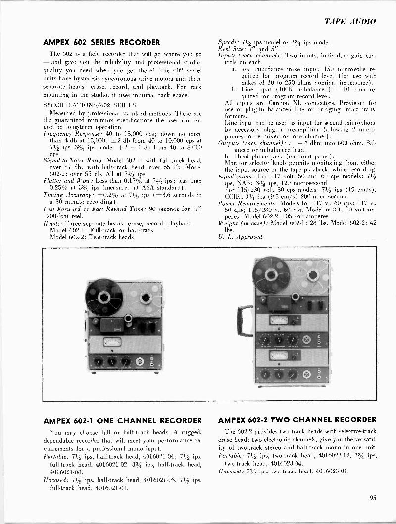
TAPE AUDIO
AMPEX 602 SERIES RECORDER
The 602 is a field recorder that will go where you go - and give you the reliability and professional studio - quality you need when you get there! The 602 series units have hysteresis synchronous drive motors and three separate heads: erase, record, and playback. For rack mounting in the studio, it uses minimal rack space.
SPECIFICATIONS/602 SERIES Measured by professional standard methods. These are
the guaranteed minimum specifications the user can ex- pect in long-term operation. Frequency Response: 40 to 15,000 cps; down no more
than 4 db at 15,000; ±2 db from 40 to 10,000 cps at 71/2 ips. 33/4 ips model +2 -4 db from 40 to 8,000 cps.
Signal -to -Noise Ratio: Model 602-1: with full track head, over 57 db; with half-track head, over 55 db. Model 602-2: over 55 db. All at 71/2 ips.
Flutter and Wow: Less than 0.17% at 71/2 ips; less than 0.25% at 33/4 ips (measured at ASA standard) .
Timing Accuracy: ±0.2% at 71/2 ips (±3.6 seconds in a 30 minute recording).
Fast Forward or Fast Rewind Time: 90 seconds for full 1200 -foot reel. Heads: Three separate heads: erase, record, playback.
Model 602-1: Full -track or half-track Model 602-2: Two -track heads
AMPEX 602-1 ONE CHANNEL RECORDER
You may choose full or half-track heads. A rugged, dependable recorder that will meet your performance re- quirements for a professional mono input. Portable: 71/2 ips, half-track head, 4016021-04; 71/2 ips,
full -track head, 4016021-02. 33/4 ips, half-track head, 4016021-08.
Uncased: 71/2 ips, half-track head, 4016021-03. 71/2 ips, full -track head, 4016021-01.
Speeds: 71/2 ips model or 33/4 ips model. Reel Size: 7" and 5". Inputs (each channel): Two inputs, individual gain con-
trols on each. a. low impedance mike input, 150 microvolts re-
quired for program record level (for use with mikes of 30 to 250 ohms nominal impedance).
b. Line input (100K unbalanced), - 10 dbm re- quired for program record level.
All inputs are Cannon XL connectors. Provision for use of plug-in balanced line or bridging input trans- formers. Line input can be used as input for second microphone by accessory plug-in preamplifier (allowing 2 micro- phones to be mixed on one channel).
Outputs (each channel) : a. +4 dbm into 600 ohm. Bal- anced or unbalanced load.
b. Head phone jack (on front panel). Monitor selector knob permits monitoring from either the input source or the tape playback, while recording.
Equalization: For 117 volt, 50 and 60 cps models: 71/2 ips, NAB; 33/4 ips, 120 microsecond. For 115/230 volt, 50 cps models: 71/2 ips (19 cm/s), CCIR; 33/4 ips (9.5 cm/s) 200 microsecond.
Power Requirements: Models for 117 v., 60 cps; 117 v., 50 cps; 115/230 v., 50 cps. Model 602-1, 70 volt-am- peres; Model 602-2, 105 volt-amperes.
Weight (in case) : Model 602-1: 28 lbs. Model 602-2: 42 lbs.
U. L. Approved
AMPEX 602-2 TWO CHANNEL RECORDER
The 602-2 provides two -track heads with selective -track erase head; two electronic channels, give you the versatil- ity of two -track stereo and half-track mono in one unit. Portable: 71/2 ips, two -track head, 4016023-02. 33/4 ips,
two -track head, 4016023-04. Uncased: 71/2 ips, two -track head, 4016023-01.
95

AMPEX 622 SPEAKER/AMPLIFIER
The 622 unit gives you "on -the -spot" studio -quality
playback for demonstration or monitoring. Its 10 watt
amplifier provides ample volume for a medium size audi-
torium.
SPECIFICATIONS/622 SPEAKER -AMPLIFIER Overall Frequency Response (in air): Essentially flat
acoustically, range better than 65-10,000 cps.
Speaker Size: Special design 8" full -range speaker. Power Output: 10 watts amplifier power with no audible
harmonic distortion. Speaker can handle full power. Signal -to -Noise: Amplifier noise (including hum), 70 db
below rated output. Controls & Connections: Volume control, bass -treble con-
trol, power switch and on -off indicator light. Built-in AC convenience outlet. Audio input connector is con- centric pin type. External speaker connection is head- phone type jack.
Equalization: Single control on front panel provides ad- justment, boosting bass and attenuating treble or vice versa. Maximum bass boost 6 db relative to treble. Maximum treble boost 6 db relative to bass.
External Speaker Feed: Use of "SPEAKER" jack auto- matically cuts out the 622's internal speaker and re-
ciprocal network. Flat amplifier output is fed to the external speaker.
Impedance: Inputs, 100,000 ohms. Output, 12 ohms to ex-
ternal speaker. Power Requirement: 117 volts, 50 or 60 cycles, 0.5 amps,
55 watts. Weight: 25 pounds. U. L. Approved
DIMENSIONS/602.1 602-2 622
Transport top area: 9t" x 121/2". Electronic top area: 61/8" x 121/2".
(two electronic sections in Model 602-2). Depth below top plate: 5". Overall size, include carrying case:
Model 602-1; 8" x 133/4" x 161/2" Model 602-2; 8" x 133/4' x 23"
Rack Space: will mount in standard 19" width rack, with appropriate Ampex adapter panel.
Model 602-1 with #864 Adapter Panel, takes only
171/2" of vertical rack space.
Model 602-2 with #865 Adapter Panel, takes only
233/4" of vertical rack space.
Model 622 speaker/amplifier, overall size in carrying
case: 13" x 16" x 8". Catalog No. 01-0622. Port No. 099 2484 000
ACCESSORIES FOR AMPEX 602 SERIES
Order By Type
Number 01-0897 Minor Hardware Kit
Portable case - for 602-1 one -channel model 01-0854 for 602-2 two -channel model 01-0855
Rack Mount Adapter - for 602-1 01-0864 for 602-2 01-0865
Operation & Maintenance Manual (602 series) 89-0080 Operator's Guide for 622 Amplifier/Speaker 89-0099 Professional Accessory Kit (includes head
cleaner, demagnetizer, motor oil, Q -tips) 01-0894 Head Demagnetizer 820 Head Cleaner, 4 -oz. Can 823
Lubricating Oil, approved, in plastic oiler bottle 825 Alignment Tapes (see separate Alignment Tape Price Schedule and descriptions) . Speed and power frequency conversion kits available on request from Ampex Service Engineering Department.
AMPEX TYPE AG -350
The ampex AG -350 series transport retains the time
proven 350 series transport features. Outstanding features
include automatic equalization, rigid top plate, direct
drive capstan, accurate traction pressure through positive
solenoid control of capstan idler which disengages auto-
matically when power is shut off, take up arm to eliminate
tape bounce, push button control panel, 101/2 inch reels,
tape speed switch automatically switches equalization,
96
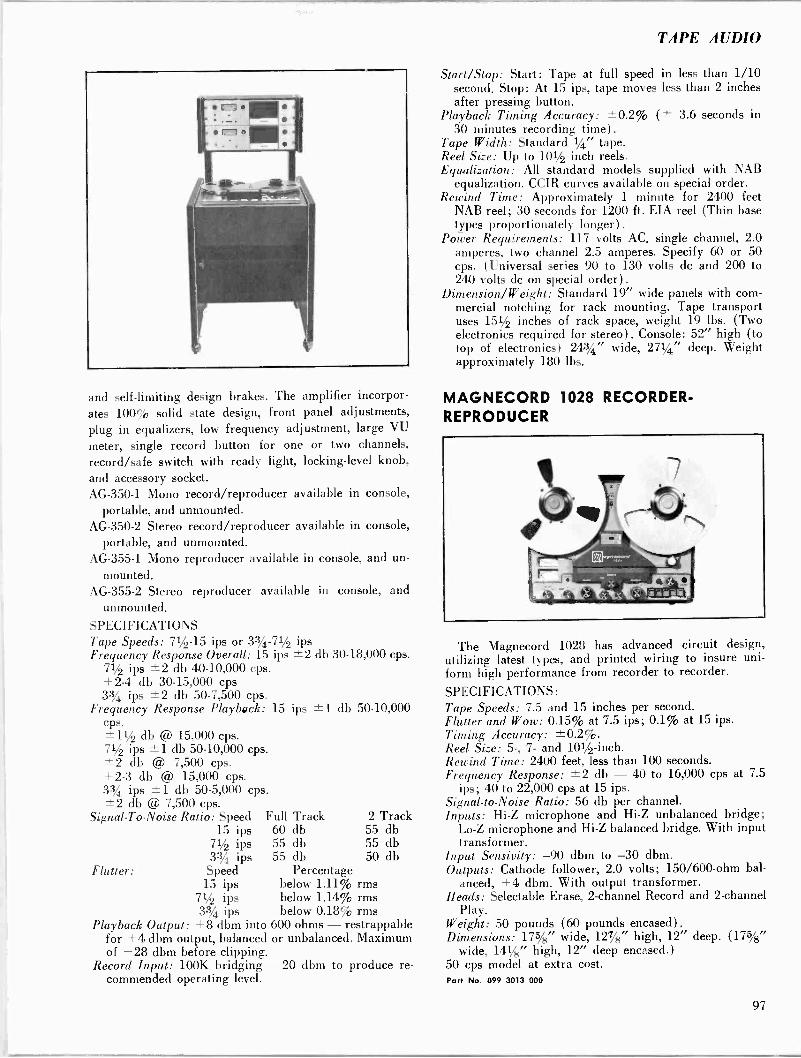
TAPE AUDIO
and self-limiting design brakes. The amplifier incorpor- ates 100% solid state design, front panel adjustments, plug in equalizers, low frequency adjustment, large VU
meter, single record button for one or two channels, record/safe switch with ready light, locking -level knob, and accessory socket. AG -350-1 Mono record/reproducer available in console,
portable, and unmounted. AG -350-2 Stereo record/reproducer available in console,
portable, and unmounted. AG -355-1 Mono reproducer available in console, and un-
mounted. AG -355-2 Stereo reproducer available in console, and
unmounted. SPECIFICATIONS Tape Speeds: 71/2-15 ips or 33/4 - Frequency Response Overall: 15
71/2 ips ±2 db 40-10,000 cps. +2-4 db 30-15,000 cps 33/4 ips ±2 db 50-7,500 cps.
Frequency Response Playback: cps. -1-11/2 db @ 15,000 cps. 71/2 ips ±1 db 50-10,000 cps. ±2 db @ 7,500 cps. +2-3 db @ 15,000 cps. 3% ips ± 1 db 50-5,000 cps. ±2 db @ 7,500 cps.
Signal -To -Noise Ratio: Speed 15 ips
71/2 ips 33/4 ips
Flutter: Speed 15 ips
71/2 ips 33/4 ips
Playback Output: +8 dbm into for +4 dbm output, balanced of +28 dbm before clipping.
Record Input: 100K bridging commended operating level.
71/2 ips ips ±2 db 30-18,000 cps.
15 ips ±1 db 50-10,000
Full Track 60 db 55 db 55 db
Percentage below 1.11% rms below 1.14% rms below 0.18% rms
600 ohms - restrappable or unbalanced. Maximum
2 Track 55 db 55 db 50 db
- 20 dbm to produce re-
Start/Stop: Start: Tape at full speed in less than 1/10 second. Stop: At 15 ips, tape moves less than 2 inches after pressing button.
Playback Timing Accuracy: ±0.2% (± 3.6 seconds in 30 minutes recording time).
Tape Width: Standard 1/4" tape. Reel Size: Up to 101/2 inch reels. Equalization: All standard models supplied with NAB
equalization. CCIR curves available on special order. Rewind Time: Approximately 1 minute for 2400 feet
NAB reel; 30 seconds for 1200 ft. EIA reel (Thin base types proportionately longer).
Power Requirements: 117 volts AC, single channel, 2.0 amperes, two channel 2.5 amperes. Specify 60 or 50 cps. (Universal series 90 to 130 volts do and 200 to 240 volts dc on special order).
Dimension/Weight: Standard 19" wide panels with com- mercial notching for rack mounting. Tape transport uses 151/2 inches of rack space, weight 19 lbs. (Two electronics required for stereo). Console: 52" high (to top of electronics) 243/4" wide, 271/4" deep. Weight approximately 180 lbs.
MAGNECORD 1028 RECORDER- REPRODUCER
The Magnecord 1028 has advanced circuit design, utilizing latest types, and printed wiring to insure uni- form high performance from recorder to recorder.
SPECIFICATIONS: Tape Speeds: 7.5 and 15 inches per second. Flutter and Wow: 0.15% at 7.5 ips; 0.1% at 15 ips. Timing Accuracy: ±0.2%. Reel Size: 5-, 7- and 101/2 -inch. Rewind Time: 2400 feet, less than 100 seconds. Frequency Response: ±2 db - 40 to 16,000 cps at 7.5
ips; 40 to 22,000 cps at 15 ips. Signal -to -Noise Ratio: 56 db per channel. Inputs: Hi -Z microphone and Hi -Z unbalanced bridge;
Lo -Z microphone and Hi -Z balanced bridge. With input transformer.
Input Sensivity: -90 dbm to -30 dbm. Outputs: Cathode follower, 2.0 volts; 150/600 -ohm bal-
anced, +4 dbm. With output transformer. Heads: Selectable Erase, 2 -channel Record and 2 -channel
Play. Weight: 50 pounds (60 pounds encased). Dimensions: 175/8" wide, 127/8" high, 12" deep. (175/8"
wide, 141/8" high, 12" deep encased.) 50 cps model at extra cost. Part No. 099 3013 000
97
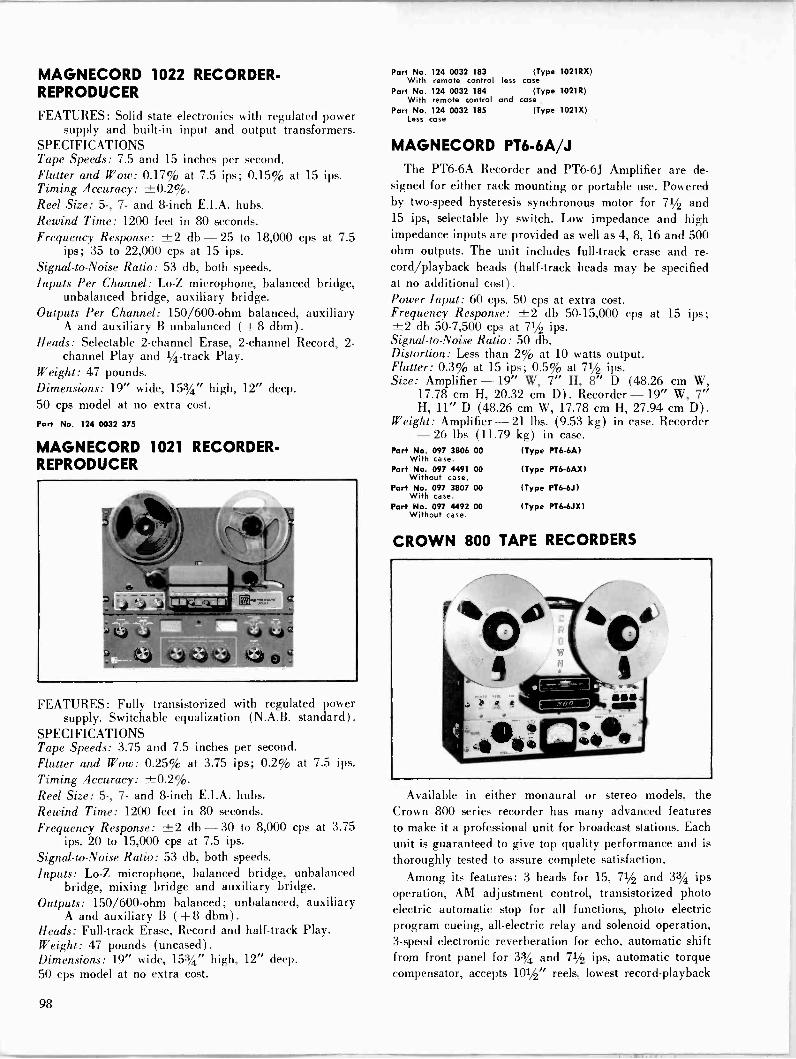
MAGNECORD 1022 RECORDER - REPRODUCER
FEATURES: Solid state electronics with regulated power supply and built-in input and output transformers.
SPECIFICATIONS Tape Speeds: 7.5 and 15 inches per second. Flutter and Wow: 0.17% at 7.5 ips; 0.15% at 15 ips. Timing Accuracy: ±0.2%. Reel Size: 5-, 7- and 8 -inch E.I.A. hubs. Rewind Time: 1200 feet in 80 seconds. Frequency Response: ±2 db - 25 to 18,000 cps at 7.5
ips; 35 to 22,000 cps at 15 ips. Signal -to -Noise Ratio: 53 db, both speeds. Inputs Per Channel: Lo -Z microphone, balanced bridge,
unbalanced bridge, auxiliary bridge. Outputs Per Channel: 150/600 -ohm balanced, auxiliary
A and auxiliary B unbalanced (+ 8 dbm) .
Heads: Selectable 2 -channel Erase, 2 -channel Record, 2 - channel Play and 1/4 -track Play.
Weight: 47 pounds. Dimensions: 19" wide, 153/4" high, 12" deep. 50 cps model at no extra cost.
Part No. 124 0032 375
MAGNECORD 1021 RECORDER- REPRODUCER
FEATURES: Fully transistorized with regulated power supply. Switchable equalization (N.A.B. standard).
SPECIFICATIONS Tape Speeds: 3.75 and 7.5 inches per second. Flutter and Wow: 0.25% at 3.75 ips; 0.2% at 7.5 ips. Timing Accuracy: ±0.2%. Reel Size: 5-, 7- and 8 -inch E.I.A. hubs. Rewind Time: 1200 feet in 80 seconds. Frequency Response: ±2 db - 30 to 8,000 cps at 3.75
ips. 20 to 15,000 cps at 7.5 ips.
Signal -to -Noise Ratio: 53 db, both speeds. Inputs: Lo -Z microphone, balanced bridge, unbalanced
bridge, mixing bridge and auxiliary bridge. Outputs: 150/600 -ohm balanced; unbalanced, auxiliary
A and auxiliary B (+ 8 dbm) .
Heads: Full -track Erase, Record and half-track Play. Weight: 47 pounds (uncased). Dimensions: 19" wide, 153/4" high, 12" deep. 50 cps model at no extra cost.
Part No. 124 0032 183 (Type 1021RX) With remote control less case
Part No. 124 0032 184 (Type 1021R) With remote control and case
Part No. 124 0032 185 (Type 1021X) Less case
MAGNECORD PT6-6A/J The PT6-6A Recorder and PT6-6J Amplifier are de-
signed for either rack mounting or portable use. Powered by two -speed hysteresis synchronous motor for 71/2 and 15 ips, selectable by switch. Low impedance and high impedance inputs are provided as well as 4, 8, 16 and 500 ohm outputs. The unit includes full -track erase and re- cord/playback heads (half-track heads may be specified at no additional cost). Power Input: 60 cps. 50 cps at extra cost. Frequency Response: ±2 db 50-15,000 cps at 15 ips; ±2 db 50-7,500 cps at 71/2 ips. Signal -to -Noise Ratio: 50 db. Distortion: Less than 2% at 10 watts output. Flutter: 0.3% at 15 ips; 0.5% at 71/2 ips. Size: Amplifier - 19" W, 7" H, 8" D (48.26 cm W,
17.78 cm H, 20.32 cm D) . Recorder - 19" W, 7" H, 11" D (48.26 cm W, 17.78 cm H, 27.94 cm D) .
Weight: Amplifier - 21 lbs. (9.53 kg) in case. Recorder - 26 lbs (1L79 kg) in case.
Part No. 097 3806 00 (Type PT6-6A) With case.
Part No. 097 4491 00 (Type PT6-6AX) Without case.
Part No. 097 3807 00 (Type PT6-6J) With case.
Part No. 097 4492 00 (Type PT6-6JX) Without case.
CROWN 800 TAPE RECORDERS
Available in either monaural or stereo models, the Crown 800 series recorder has many advanced features to make it a professional unit for broadcast stations. Each unit is guaranteed to give top quality performance and is thoroughly tested to assure complete satisfaction.
Among its features: 3 heads for 15, 71/2 and 33/4 ips operation, AM adjustment control, transistorized photo electric automatic stop for all functions, photo electric program cueing, all -electric relay and solenoid operation, 3 -speed electronic reverberation for echo, automatic shift from front panel for 33/4 and 71/2 ips, automatic torque compensator, accepts 101/2" reels, lowest record -playback
98
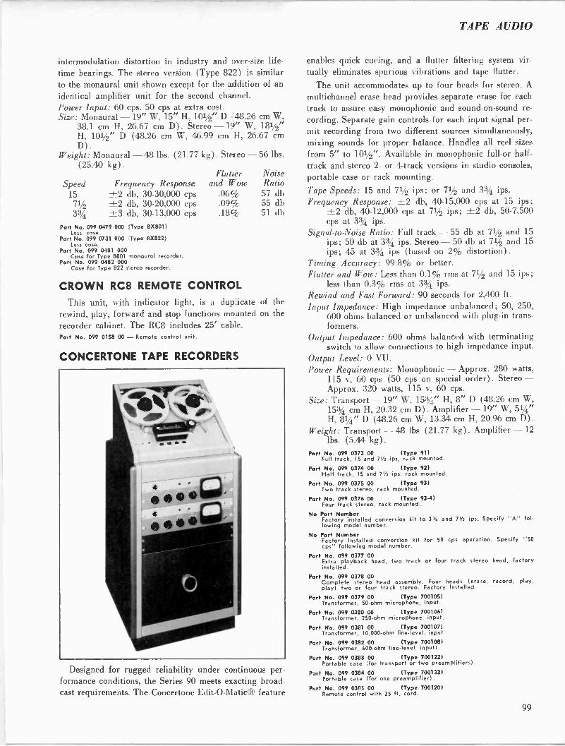
TAPE AUDIO
intermodulation distortion in industry and over -size life-
time bearings. The stereo version (Type 822) is similar to the monaural unit shown except for the addition of an identical amplifier unit for the second channel. Power Input: 60 cps. 50 cps at extra cost. Size: Monaural - 19" W, 15" H, 101/2" D _48.26 cm W,
38.1 cm H, 26.67 cm D) . Stereo - 19" W, 181/2" H, 101/2" D (48.26 cm W, 46.99 cm H, 26.67 cm D).
Weight: Monaural - 48 lbs. (21.77 kg) . Stereo - 56 lbs. (25.40 kg).
Flutter Noise Speed Frequency Response and Wow Ratio
15 ±2 db, 30.30,000 cps .06% 57 db
71/2 ±2 db, 30-20,000 cps .09% 55 db
3314 ±3 db, 30-13,000 cps .18% 51 db
Part No. 099 0479 000 !Type 8X801) less case.
Part No. 099 0731 000 Type BX822) less case.
Part No. 099 0481 000 Case for Type 8801 monaural recorder.
Part No. 099 0482 000 Case for Type 822 s-ereo recorder.
CROWN RC8 REMOTE CONTROL
This unit, with indicator light, is a duplicate of the
rewind, play, forward and stop functions mounted on the recorder cabinet. The RC8 includes 25' cable. Part No. 099 0158 00 - Remote control unit.
CONCERTONE TAPE RECORDERS
Designed for rugged reliability under continuous per- formance conditions, the Series 90 meets exacting broad- cast requirements. The Concertone Edit-O-Matic® feature
enables quick cueing, and a flutter filtering system vir-
tually eliminates spurious vibrations and tape flutter.
The unit accommodates up to four heads for stereo. A
multichannel erase head provides separate erase for each track to assure easy monophonic and sound -on -sound re-
cording. Separate gain controls for each input signal per- mit recording from two different sources simultaneously, mixing sounds for proper balance. Handles all reel sizes
from 5" to 101/2". Available in monophonic full -or half- track and stereo 2- or 4 -track versions in studio consoles, portable case or rack mounting.
Tape Speeds: 15 and 71/2 ips; or 71/2 and 33/4 ips. Frequency Response: ±2 db, 40-15,000 cps at 15 ips;
±2 db, 40-12,000 cps at 71/2 ips; ±2 db, 50-7,500 cps at 3% ips.
Signal -to -Noise Ratio: Full track - 55 db at 71/2 and 15 ips; 50 db at 33/4 ips. Stereo- 50 db at 71/2 and 15 ips; 45 at 3% ips (based on 2% distortion).
Timing Accuracy: 99.8% or better. Flutter and Wow: Less than 0.1% rms at 71/2 and 15 ips;
less than 0.3% rms at 3% ips. Rewind and Fast Forward: 90 seconds for 2,400 ft.
Input Impedance: High impedance unbalanced; 50, 250, 600 ohms balanced or unbalanced with plug-in trans- formers.
Output Impedance: 600 ohms balanced with terminating switch to allow connections to high impedance input.
Output Level: 0 VU. Power Requirements: Monophonic - Approx. 280 watts,
115 v, 60 cps (50 cps on special order). Stereo - Approx. 320 watts, 115 v, 60 cps.
Size: Transport - 19" W, 153/4" H, 8" D (48.26 cm W, 15% cm H, 20.32 cm D) . Amplifier - 19" W, 51/4" H, 81/4" D (48.26 cm W, 13.34 cm H, 20.96 cm D) .
Weight: Transport - 48 lbs (21.77 kg) . Amplifier -12 lbs. (5.44 kg).
Port No. 099 0373 00 (Type 91) Full track, 15 and 71/2 ips, rack mounted.
Port No. 099 0374 00 (Type 92) Half track, 15 and 71/2 ips, rack mounted.
Part No. 099 0375 00 (Type 93) Two track stereo, rack mounted.
Part No. 099 0376 00 (Type 93-4) Four track stereo, rack mounted.
No Part Number Factory installed conversion kit to 32/4 and 71/2 ips. Specify "A" fol- lowing model number.
No Part Number Factory installed conversion kit for 50 cps operation. Specify "50 cps" following model number.
Part No. 099 0377 00 Extra playback head, two track or four track stereo head, factory installed.
P ort No. 099 0378 00 Complete stereo head assembly. Four heads (erase, record, play, play) two or four track stereo. Factory installed.
P art No. 099 0379 00 (Type 700105) Transformer, 50 -ohm microphone, input.
Part No. 099 0380 00 (Type 700106) Transformer, 250 -ohm microphone, input.
Part No. 099 0381 00 (Type 700107) Transformer, 10,000 -ohm line- evel, input.
Part No. 099 0382 00 (Type 700108) Transformer, 600 -ohm line -level, input).
Part No. 099 0383 00 (Type 700122) Portable case (for transport or two preamplifiers).
Part No. 099 0384 00 (Type 700133) Portable case (for one preamplifier).
P art No. 099 0385 00 (Type 700120) Remote control with 25 ft. cord.
99
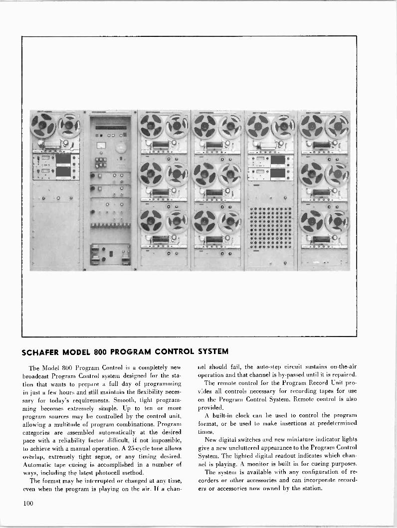
SCHAFER MODEL 800 PROGRAM CONTROL
The Model 800 Program Control is a completely new
broadcast Program Control system designed for the sta-
tion that wants to prepare a full day of programming in just a few hours and still maintain the flexibility neces-
sary for today's requirements. Smooth, tight program- ming becomes extremely simple. Up to ten or more program sources may be controlled by the control unit, allowing a multitude of program combinations. Program categories are assembled automatically at the desired pace with a reliability factor difficult, if not impossible, to achieve with a manual operation. A 25 -cycle tone allows overlap, extremely tight segue, or any timing desired. Automatic tape cueing is accomplished in a number of ways, including the latest photocell method.
The format may be interrupted or changed at any time, even when the program is playing on the air. If a chan-
ee ei eile ee e e e e e e e e e e e e eóee et. eeee ®eeeeeeeee a e e e cc., e e e.. ee.e u,.. e e e e e e 61,06 e G oeeeveeeee e e e e Y e e e It e
SYSTEM
nel should fail, the auto -step circuit sustains on -the -air operation and that channel is by-passed until it is repaired.
The remote control for the Program Record Unit pro- vides all controls necessary for recording tapes for use
on the Program Control System. Remote control is also provided.
A built-in clock can be used to control the program format, or be used to make insertions at predetermined times.
New digital switches and new miniature indicator lights give a new uncluttered appearance to the Program Control System. The lighted digital readout indicates which chan- nel is playing. A monitor is built in for cueing purposes.
The system is available with any configuration of re-
corders or other accessories and can incorporate record- ers or accessories now owned by the station.
100
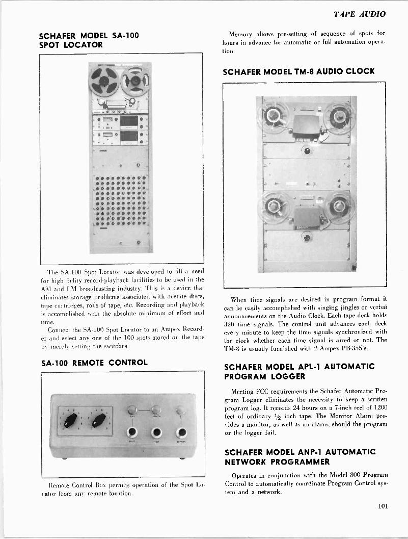
TAPE AUDIO
SCHAFER MODEL SA -100 SPOT LOCATOR
di %- .'"Z".1-1
1x1
=.110 r""ri
O
MOM
V
V
The SA -100 Spot Locator was developed to fill a need
for high fielity record -playback facilities to be used in the
AM and FM broadcasting industry. This is a device that eliminates storage problems associated with acetate discs,
tape cartridges, rolls of tape, etc. Recording and playback
is accomplished with the absolute minimum of effort and
time. Connect the SA -100 Spot Locator to an Ampex Record-
er and select any one of the 100 spots stored on the tape
by merely setting the switches.
SA -100 REMOTE CONTROL
Remote Control Box permits operation of the Spot Lo-
cator from any remote location.
Memory allows pre-setting of sequence of spots for
hours in advance for automatic or full automation opera-
tion.
SCHAFER MODEL TM -8 AUDIO CLOCK
When time signals are desired in program format it
can be easily accomplished with singing jingles or verbal announcements on the Audio Clock. Each tape deck holds
320 time signals. The control unit advances each deck
every minute to keep the time signals synchronized with the clock whether each time signal is aired or not. The TM -8 is usually furnished with 2 Ampex PB -355's.
SCHAFER MODEL APL -1 AUTOMATIC PROGRAM LOGGER
Meeting FCC requirements the Schafer Automatic Pro- gram Logger eliminates the necessity to keep a written program log. It records 24 hours on a 7 -inch reel of 1200 feet of ordinary 1/2 inch tape. The Monitor Alarm pro- vides a monitor, as well as an alarm, should the program or the logger fail.
SCHAFER MODEL ANP-1 AUTOMATIC NETWORK PROGRAMMER
Operates in conjunction with the Model 800 Program Control to automatically coordinate Program Control sys-
tem and a network.
101
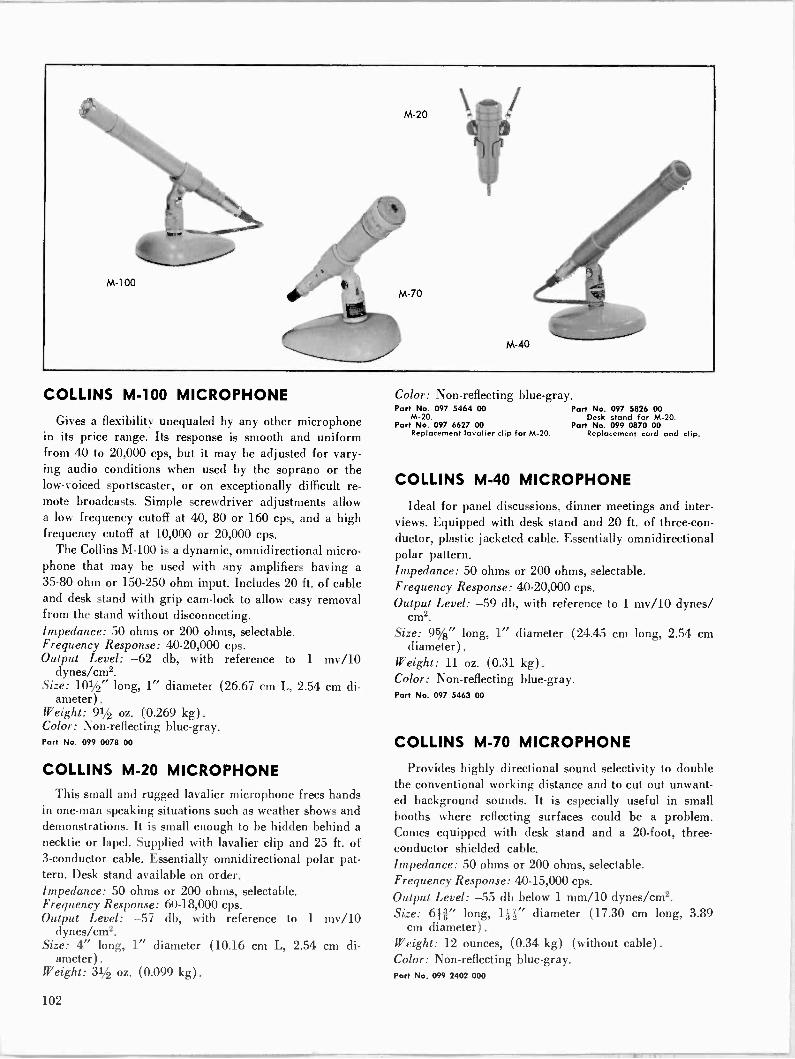
M-100
M-20
M-70
eee M-40
COLLINS M-100 MICROPHONE
Gives a flexibility unequaled by any other microphone in its price range. Its response is smooth and uniform from 40 to 20,000 cps, but it may be adjusted for vary- ing audio conditions when used by the soprano or the low -voiced sportscaster, or on exceptionally difficult re- mote broadcasts. Simple screwdriver adjustments allow a low frequency cutoff at 40, 80 or 160 cps, and a high frequency cutoff at 10,000 or 20,000 cps.
The Collins M-100 is a dynamic, omnidirectional micro- phone that may be used with any amplifiers having a 35-80 ohm or 150-250 ohm input. Includes 20 ft. of cable and desk stand with grip cam -lock to allow easy removal from the stand without disconnecting. Impedance: 50 ohms or 200 ohms, selectable. Frequency Response: 40-20,000 cps. Output Level: -62 db, with reference to 1 my/10
dyneslcm2. Size: 101/2" long, 1" diameter (26.67 cm L, 2.54 cm di-
ameter) .
Weight: 91/2 oz. (0.269 kg) .
Color: Non-reflecting blue -gray. Part No. 099 0078 00
COLLINS M-20 MICROPHONE This small and rugged lavalier microphone frees hands
in one-man speaking situations such as weather shows and demonstrations. It is small enough to be hidden behind a necktie or lapel. Supplied with lavalier clip and 25 ft. of 3 -conductor cable. Essentially omnidirectional polar pat- tern. Desk stand available on order. Impedance: 50 ohms or 200 ohms, selectable. Frequency Response: 60-18,000 cps. Output Level: -57 db, with reference to 1 my/10
dynes/cm2. Size: 4" long, 1" diameter (10.16 cm L, 2.54 cm di-
ameter) . Weight: 31/2 oz. (0.099 kg).
Color: Non-reflecting blue -gray. Part No. 097 5464 00 Part No. 097 5826 00
M-20. Desk stand for M-20. Part No. 097 6627 00 Part No. 099 0870 00
Replacement lavalier clip for M-20. Replacement cord and clip.
COLLINS M-40 MICROPHONE
Ideal for panel discussions, dinner meetings and inter- views. Equipped with desk stand and 20 ft. of three -con- ductor, plastic jacketed cable. Essentially omnidirectional polar pattern. Impedance: 50 ohms or 200 ohms, selectable. Frequency Response: 40-20,000 cps. Output Level: -59 db, with reference to 1 my/10 dynes/
cm2.
Size: 95/8" long, 1" diameter (24.45 cm long, 2.54 cm diameter) .
Weight: 11 oz. (0.31 kg). Color: Non-reflecting blue -gray. Part No. 097 5463 00
COLLINS M-70 MICROPHONE
Provides highly directional sound selectivity to double the conventional working distance and to cut out unwant- ed background sounds. It is especially useful in small booths where reflecting surfaces could be a problem. Comes equipped with desk stand and a 20 -foot, three - conductor shielded cable. Impedance: 50 ohms or 200 ohms, selectable. Frequency Response: 40-15,000 cps. Output Level: -55 db below 1 mm/10 dynes/cm2. Size: 6H" long, 111" diameter (17.30 cm long, 3.89
cm diameter) .
Weight: 12 ounces, (0.34 kg) (without cable). Color: Non-reflecting blue -gray. Part No. 099 2402 000
102
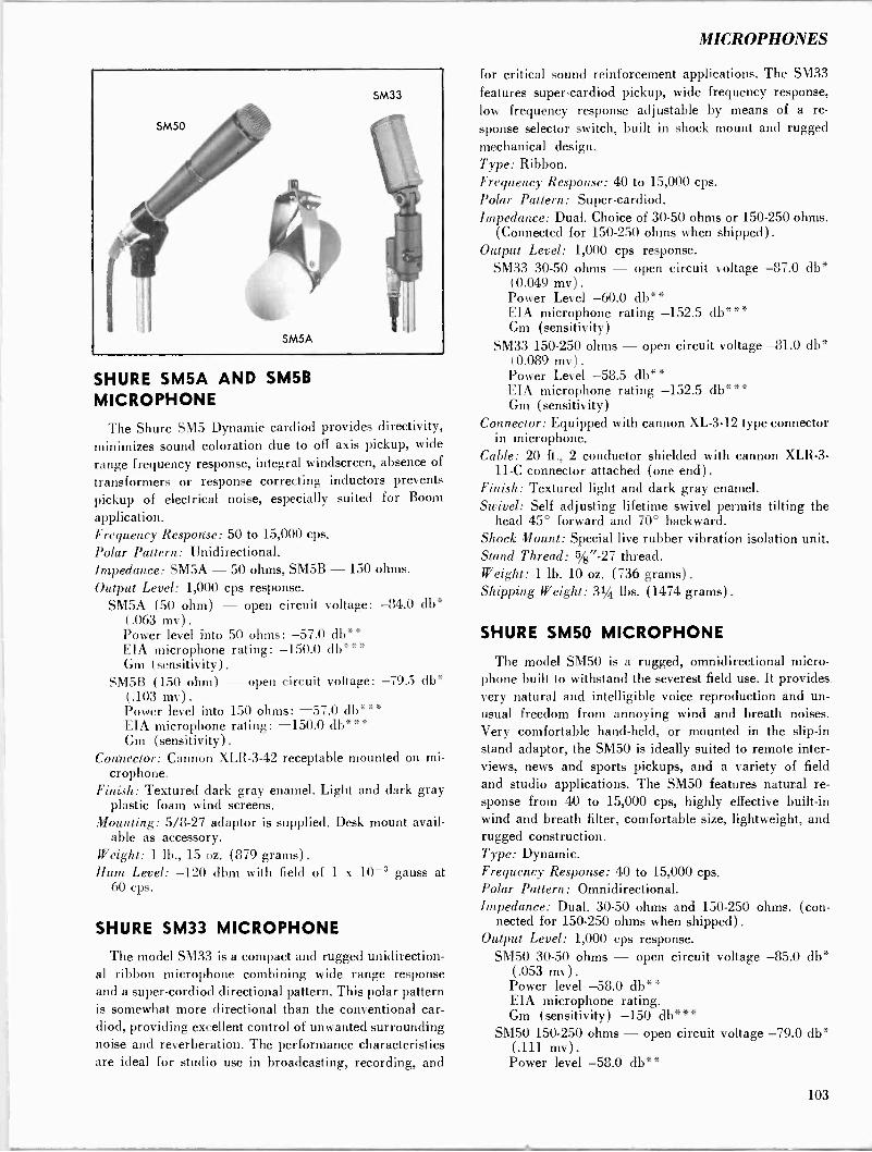
MICROPHONES
SHURE SM5A AND SM5B MICROPHONE
'l'he Shure SM5 Dynamic cardiod provides directivity, minimizes sound coloration due to off axis pickup, wide
range frequency response, integral windscreen, absence of
transformers or response correcting inductors prevents pickup of electrical noise, especially suited for Boom
application. Frequency Response: 50 to 15,000 cps. Polar Pattern: Unidirectional. Impedance: SM5A - 50 ohms, SM5B - 150 ohms.
Output Level: 1,000 cps response. SM5A (50 ohm) - open circuit voltage: -84.0 db*
(.063 mv). Power level into 50 ohms: -57.0 db** EIA microphone rating: -150.0 db"*" Gm (sensitivity) .
SM5B (150 ohm) - open circuit voltage: -79.5 db* (.103 mv). Power level into 150 ohms: -57.0 db*** EIA microphone rating: -150.0 db*" Gm (sensitivity).
Connector: Cannon XLR-3-42 receptable mounted on mi- crophone.
Finish: Textured dark gray enamel. Light and dark gray plastic foam wind screens.
Mounting: 5/8-27 adaptor is supplied. Desk mount avail- able as accessory.
Weight: 1 lb., 15 oz. (879 grams) .
Hum Level: -120 dbm with field of 1 x 10⁻³ gauss at 60 cps.
SHURE SM33 MICROPHONE
The model SM33 is a compact and rugged unidirection- al ribbon microphone combining wide range response and a super-cordiod directional pattern. This polar pattern is somewhat more directional than the conventional car- diod, providing excellent control of unwanted surrounding noise and reverberation. The performance characteristics are ideal for studio use in broadcasting, recording, and
for critical sound reinforcement applications. The SM33
features super-cardiod pickup, wide frequency response, low frequency response adjustable by means of a re-
sponse selector switch, built in shock mount and rugged mechanical design. Type: Ribbon. Frequency Response: 40 to 15,000 cps. Polar Pattern: Super-cardiod. Impedance: Dual. Choice of 30-50 ohms or 150-250 ohms.
(Connected for 150-250 ohms when shipped) .
Output Level: 1,000 cps response. SM33 30-50 ohms - open circuit voltage -87.0 db*
(0.049 mv) .
Power Level -60.0 db** EIA microphone rating -152.5 db*** Gm (sensitivity)
SM33 150-250 ohms - open circuit voltage -81.0 db* (0.089 mv) .
Power Level -58.5 db** EIA microphone rating -152.5 db*** Gm (sensitivity)
Connector: Equipped with cannon XL -3-12 type connector in microphone.
Cable: 20 ft., 2 conductor shielded with cannon XLR-3- 11-C connector attached (one end).
Finish: Textured light and dark gray enamel. Swivel: Self adjusting lifetime swivel permits tilting the
head 45° forward and 70° backward. Shock Mount: Special live rubber vibration isolation unit. Stand Thread: 5/8"-27 thread. Weight: 1 lb. 10 oz. (736 grams). Shipping Weight: 31/4 lbs. (1474 grams) .
SHURE SM50 MICROPHONE
The model SM50 is a rugged, omnidirectional micro- phone built to withstand the severest field use. It provides very natural and intelligible voice reproduction and un- usual freedom from annoying wind and breath noises. Very comfortable hand-held, or mounted in the slip -in stand adaptor, the SM50 is ideally suited to remote inter- views, news and sports pickups, and a variety of field and studio applications. The SM50 features natural re- sponse from 40 to 15,000 cps, highly effective built-in wind and breath filter, comfortable size, lightweight, and rugged construction. Type: Dynamic. Frequency Response: 40 to 15,000 cps. Polar Pattern: Omnidirectional. Impedance: Dual. 30-50 ohms and 150-250 ohms. (con-
nected for 150-250 ohms when shipped). Output Level: 1,000 cps response.
SM50 30-50 ohms - open circuit voltage -85.0 db* (.053 mv). Power level -58.0 db** EIA microphone rating. Gm (sensitivity) -150 db***
SM50 150-250 ohms - open circuit voltage -79.0 db* (.111 mv) .
Power level -58.0 db**
103
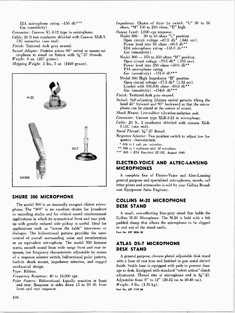
EIA microphone rating -150 db*** Gm (sensitivity) .
Connector: Cannon XL -3-12 type in microphone. Cable: 20 ft two conductor shielded with Cannon XLR-3-
11C connector (one end). Finish: Textured dark gray enamel. Swivel Adapter: Positive action 90° swivel to mount mi-
crophone to stand on fixture with 5/g"-27 threads. Weight: 8 oz. (227 grams). Shipping Weight: 2 lbs., 5 oz. (1049 grams) .
SHURE 300 MICROPHONE
The model 300 is an unusually compact ribbon micro- phone. The "300" is an excellent choice for broadcast or recording studio and for critical sound reinforcement applications in which its symmetrical front and rear pick- up with greatly reduced side pickup is useful. Ideal for applications such as "across the table" interviews or dialogue. The bidirectional pattern provides the same control of overall surrounding noise and reverberation as an equivalent microphone. The model 300 features warm, smooth sound from wide range front and rear re- sponse, low frequency characteristic adjustable by means of a response selector switch, bidirectional polar pattern, built-in shock mount, impedance selection, and rugged mechanical design. Type: Ribbon. Frequency Response: 40 to 15,000 cps. Polar Pattern: Bidirectional. Equally sensitive at front
and rear. Response at sides down 15 to 20 db from front and rear response.
Impedance: Choice of three by switch. "L" 30 to 50 ohms, "M" 150 to 250 ohms, "H" high.
Output Level: 1,000 cps response. Model 300 - 30 to 50 ohms "L" position.
Open circuit voltage -87.5 db* (.043 mv). Power level into 50 ohms -60.5 db** EIA microphone rating -153.0 db*** Gm (sensitivity) .
Model 300 - 150 to 250 ohms "M" position. Open circuit voltage -79.5 db* (.105 mv) .
Power level into 250 ohms -59.0 db** EIA microphone rating Gm (sensitivity) -151.0 db***
Model 300 High Impedance "H" position Open circuit voltage -57.5 db* (1.32 mv) .
Loaded with 100,000 ohms -60.0 db** Gm (sensitivity) -154.0 db***
Finish: Textured -dark gray enamel. Swivel: Self-adjusting lifetime swivel permits tilting the
head 45° forward and 90° backward so that the micro- phone can be aimed at the source of sound.
Shock Mount: Live -rubber vibration -isolation unit. Connector: Cannon type XLR-3-12 in microphone. Cable: 20 ft., 2 conductor shielded with cannon XLR-
3-11C (one end). Stand Thread: 5/g"-27 thread. Response Selector: Two position switch to adjust low fre-
quency characteristic. * 0db = 1 volt per microbar.
* * 0db = 1 milliwatt with 10 microbars. * * * 0db = EIA Standard SE -105, August 1949.
ELECTRO -VOICE AND ALTEC-LANSING MICROPHONES
A complete line of Electro -Voice and Altec-Lansing general purpose and specialized microphones, stands, call letter plates and accessories is sold by your Collins Broad- cast Equipment Sales Engineer.
COLLINS M-20 MICROPHONE DESK STAND
A small, non-reflecting blue -gray stand that holds the Collins M-20 Microphone. The M-20 is held with a felt padded clamp that allows the microphone to be slipped in and out of the stand easily. Port No. 097 5826 00
ATLAS DS -7 MICROPHONE DESK STAND
A general purpose, chrome plated adjustable desk stand with a base of cast iron and finished in gun metal shrivel finish. Stable base is equipped with pads to prevent dam- age to desk. Equipped with standard "velvet action" clutch adjustment. Thread size at microphone end is 5/8"-27. Adjustable from 8" to 12" (20.32 cm to 30.48 cm). Weight: 3 lbs. (1.36 kg) .
Port No. 097 1119 00
104
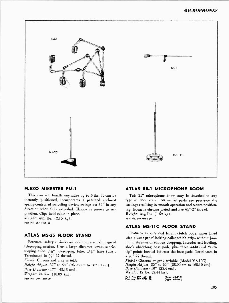
MICROPHONES
FLEXO MIKESTER FM -1
This arm will handle any mike up to 4 lbs. It can be instantly positioned, incorporates a patented enclosed spring -controlled swiveling device, swings out 36" in any direction when fully extended. Clamps or screws to any position. Clips hold cable in place. Weight: 43/4 lbs. (2.15 kg) .
Port No. 097 1499 00
ATLAS MS -25 FLOOR STAND Features "safety air -lock cushion" to prevent slippage of
telescoping section. Uses a large diameter, oversize tele- scoping tube (7/2" telescoping tube, 11/2" base tube) .
Terminated in 5/2"-27 thread. Finish: Chrome and gray wrinkle. Height Adjust: 37" to 66" (93.98 cm to 167.18 cm). Base Diameter: 17" (43.18 cm). Weight: 24 lbs. (10.89 kg) .
Part No. 097 1510 00
ATLAS BB -1 MICROPHONE BOOM This 31" microphone boom may be attached to any
type of floor stand. All swivel parts are precision die castings resulting in smooth operation and secure position- ing. Boom is chrome plated and has 5/2"-27 thread. Weight: 31/2 lbs. (1.59 kg) .
Part No. 097 0984 00
ATLAS MS -11C FLOOR STAND Features an extended length clutch body, inner lined
with a wear -proof locking collet which grips without jam- ming, slipping or sudden dropping. Includes self -leveling, shock absorbing base pads, plus three additional "anti - tip" points located between the base pads. Terminates in a 5/2"-27 thread. Finish: Chrome or gray wrinkle (Model MS -10C). Height Adjust: 35" to 65" (88.90 cm to 165.10 cm). Base Diameter: 10" (25.4 cm). Weight: 12 lbs. (5.44 kg) .
Part No. 097 1511 00 (Typo MS -11C) Part No. 097 5729 00 (Type MS -10C)
105
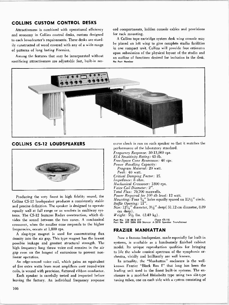
COLLINS CUSTOM CONTROL DESKS
Attractiveness is combined with operational efficiency
and economy in Collins control desks, custom designed
to each broadcaster's requirements. These desks are sturd-
ily constructed of wood covered with any of a wide range of patterns of long lasting Formica.
Among the features that may be incorporated without sacrificing attractiveness are adjustable feet, built-in rec-
COLLINS CS -12 LOUDSPEAKERS
Producing the very finest in high fidelity sound, the
Collins CS -12 loudspeaker produces a consistently stable and precise definition. The speaker is designed to operate equally well at full range or as woofers in multiway sys-
tems. The CS -12 features Radax construction, which di-
vides the sound between the two cones. A mechanical crossover, when the smaller cone responds to the higher frequencies, occurs at 1,800 cps.
A slug -type magnet is used for concentrating flux density into the air gap. This type magnet has the lowest possible leakage and greatest structural strength. The high frequency long throw voice coil remains in the air gap even on the longest of excursions to prevent non- linear operation.
An edge -wound voice coil, which gains an equivalent of five extra watts from most amplifiers over round -wire coils, is wound with precision, flattened ribbon conductor.
Each speaker is carefully tested and inspected before leaving the factory. An individual frequency response
ord compartments, hidden console cables and provisions for rack mounting.
A Collins tape cartridge system desk wing console may be placed on left wing to give complete studio facilities in one compact unit. Collins will provide free estimates upon submission of the physical layout of the studio and an outline of functions desired for inclusion in the desk. No Pare Number
curve check is run on each speaker so that it matches the performance of the laboratory standard. Frequency Response: 30-13,000 cps. EIA Sensitivity Rating: 43 db. Free -Space Cone Resonance: 40 cps. Power Handling Capacity:
Program Material: 20 watt. Peak: 40 watt.
Critical Damping Factor: 15. Impedance: 8 ohm. Mechanical Crossover: 1800 cps. Voice Coil Diameter: 2". Total Flux: 70,700 maxwells. Power Required for 100 db level: 12 watt. Mounting: Four 1/4" holes equally spaced on 111/2" circle. Baffle Opening: 11". Size: 121/4" diameter, 31/2" deep( 31.12 cm diameter, 8.89
cm deep) . Weight: 51/2 lbs. (2.49 kg) .
Part No. 124 0032 017 (Type CS -12) Part No. 099 2686 000 Stancor A-3818 Speaker Transformer
FRAZIER MANHATTAN
Now a famous loudspeaker, made especially for built-in systems, is available as a handsomely finished cabinet model. Its unique reproduction qualities for bringing to life the whole musical spectrum of the symphonic or- chestra, vividly and brilliantly are well known.
In actuality, the "Manhattan" enclosure is the well-
known Frazier "Black Box I" that long has been the leading unit used in the finest built-in systems. The en-
closure is a modified Helmholtz type using two slit -type
tuning tubes, one on each side with a system consisting of
106
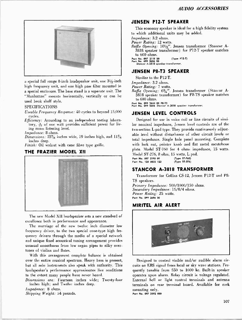
AUDIO ACCESSORIES
a special full range 8 -inch loudspeaker unit, one 31/2 -inch high frequency unit, and one high pass filter mounted in a special enclosure. The base stand is a separate unit. The "Manhattan" mounts horizontally, vertically or can be used book shelf style.
SPECIFICATIONS Useable Frequency Response: 40 cycles to beyond 15,000
cycles. Efficiency: According to an independent testing labora-
tory, h of one watt provides sufficient power for liv- ing room listening level.
Impedance: 8 ohms. Dimensions: 237/8 inches wide, 19 inches high, and 117/8
inches deep. Finish: Oil walnut with cane fibre type grille.
THE FRAZIER MODEL XII
The new Model XII loudspeaker sets a new standard of excellence both in performance and appearance.
The marriage of the new twelve inch diameter low frequency driver, to the two special cone -type high fre- quency drivers through the media of a special network and unique fixed acoustical tuning arrangement provides unusual smoothness from low organ pipes to silky over- tones of violins and flutes.
With this arrangement complete balance is obtained over the entire musical spectrum. Heavy bass is present, but all solo instruments also speak with authority. This loudspeaker's performance approximates live renditions to the extent many people have never heard. Dimensions are: Fourteen inches wide; Twenty-four
inches high; and Twelve inches deep. Impedance: 8 ohms. Shipping Weight: 54 pounds.
JENSEN P12 -T SPEAKER This economy speaker is ideal for a high fidelity system
to which additional units may be added. Impedance: 3.2 ohms. Power Rating: 12 watts. Baffle Opening: 101/2". Jensen transformer (Stancor A-
3818 speaker transformer) for P12 -T speaker matches to 600 ohms.
Part No. 097 2119 00 (Type P12 -T) Part No. 099 2686 00
Stancor A-3818 speaker transformer.
JENSEN P8 -T3 SPEAKER Similar to the P12 -T.
Impedance: 3.2 ohms. Power Rating: 7 watts. Baffle Opening: 63/4". Jensen transformer (Stancor A-
3818 speaker transformer) for P8 -TS speaker matches to 600 ohms.
Part No. 099 2644 00 P8 -T3 Part No. 099 2686 Stancor A-3818 speaker transformer.
JENSEN LEVEL CONTROLS Designed for use in voice coil or line circuits of simi-
lar nominal impedance, Jensen level controls are of the two -section L -pad type. They provide continuously adjust- able level without disturbance of other circuit levels or total impedance. Single hole panel mounting. Complete with lock nut, pointer knob and flat metal escutcheon plate. Model ST -760 for 4 ohms impedance, 15 watts. Model ST -276, 8 ohm, 15 watts, L pad. Port No. 097 2190 00 Part No. 124 0032 123
(Typo ST -760) (Typo ST -276)
STANCOR A-3818 TRANSFORMER Transformer for Collins CS -12, Jensen P12 -T and P8 -
TS speakers. Primary Impedance: 500/1000/150 ohms. Secondary Impedance: 15/8/4 ohms. Power Rating: 25 watts. Part No. 099 2686 00
MIRITEL AIR ALERT
Designed to control visible and/or audible alarm cir- cuits on EBS signal from local or sky wave stations. Fre- quently tunable from 550 to 1600 kc. Built-in speaker operates upon alarm. Relay circuit is voltage regulated. External bell or light control terminals and antenna terminals on rear terminal board. Available for rack mounting only. Part No. 097 3192 000
107
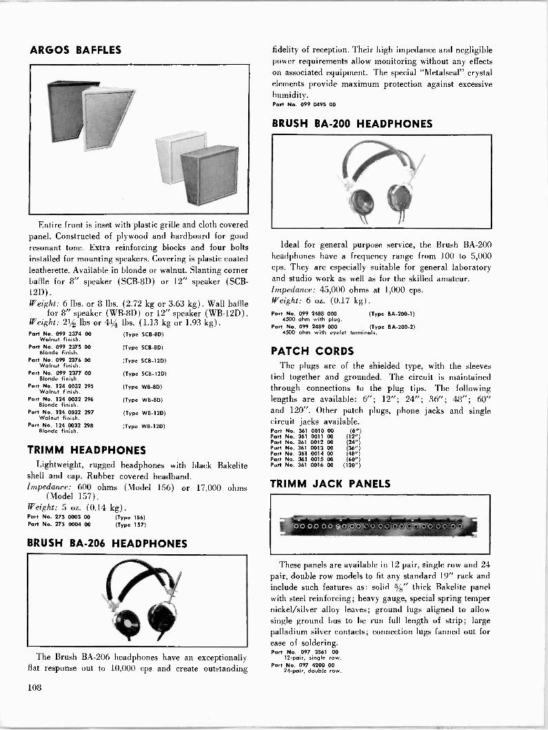
ARGOS BAFFLES
Entire front is inset with plastic grille and cloth covered panel. Constructed of plywood and hardboard for good resonant tone. Extra reinforcing blocks and four bolts installed for mounting speakers. Covering is plastic coated leatherette. Available in blonde or walnut. Slanting corner baffle for 8" speaker (SCB-8D) or 12" speaker (SCB- 12D). Weight: 6 lbs. or 8 lbs. (2.72 kg or 3.63 kg). Wall baffle
for 8" speaker (WB -8D) or 12" speaker (WB -12D) .
Weight: 21/2 lbs or 41/4 lbs. (1.13 kg or 1.93 kg) .
Part No. 099 2374 00 Walnut finish.
Part No. 099 2375 00 Blonde finish.
Part No. 099 2376 00 Walnut finish.
Part No. 099 2377 00 Blonde finish.
Port No. 124 0032 295 Walnut finish.
Part No. 124 0032 296 Blonde finish.
Part No. 124 0032 297 Walnut finish.
Part No. 124 0032 298 Blonde finish.
(Type SCB-8D)
(Type SCB-8D)
(Type SCB-12D)
(Type SCB-12D)
(Type WB -80)
(Type WB -8D)
(Type WB -12D)
(Type WB -12D)
TRIMM HEADPHONES Lightweight, rugged headphones with black Bakelite
shell and cap. Rubber covered headband. Impedance: 600 ohms (Model 156) or 17,000 ohms
(Model 157) .
Weight: 5 oz. (0.14 kg) .
Part No. 273 0003 00 (Type 156) Part No. 273 0004 00 (Type 157)
BRUSH BA -206 HEADPHONES
The Brush BA -206 headphones have an exceptionally flat response out to 10,000 cps and create outstanding
fidelity of reception. Their high impedance and negligible power requirements allow monitoring without any effects on associated equipment. The special "Metalseal" crystal elements provide maximum protection against excessive humidity. Part No. 099 0495 00
BRUSH BA -200 HEADPHONES
Ideal for general purpose service, the Brush BA -200 headphones have a frequency range from 100 to 5,000 cps. They are especially suitable for general laboratory and studio work as well as for the skilled amateur. Impedance: 45,000 ohms at 1,000 cps. Weight: 6 oz. (0.17 kg). Part No. 099 2488 000 (Type BA -200-1)
4500 ohm with plug. Part No. 099 2489 000 (Type BA -200-2)
4500 ohm with eyelet terminals.
PATCH CORDS The plugs are of the shielded type, with the sleeves
tied together and grounded. The circuit is maintained through connections to the plug tips. The following lengths are available: 6"; 12"; 24"; 36"; 48"; 60" and 120". Other patch plugs, phone jacks and single circuit jacks available. Part No. 361 0010 00 (6") Part No. 361 0011 00 (12") Port No. 361 0012 00 (24") Part No. 361 0013 00 (36") Part No. 361 0014 00 (48") Part No. 361 0015 00 (60") Part No. 361 0016 00 (120")
TRIMM JACK PANELS
, oo.0000'oloYó`o oo oo
These panels are available in 12 pair, single row and 24 pair, double row models to fit any standard 19" rack and include such features as: solid 5/8" thick Bakelite panel with steel reinforcing; heavy gauge, special spring temper nickel/silver alloy leaves; ground lugs aligned to allow single ground bus to be run full length of strip; large palladium silver contacts; connection lugs fanned out for ease of soldering. Part No. 097 3561 00
12 -pair, single row. Part No. 097 4200 00
24 -pair, double row.
108
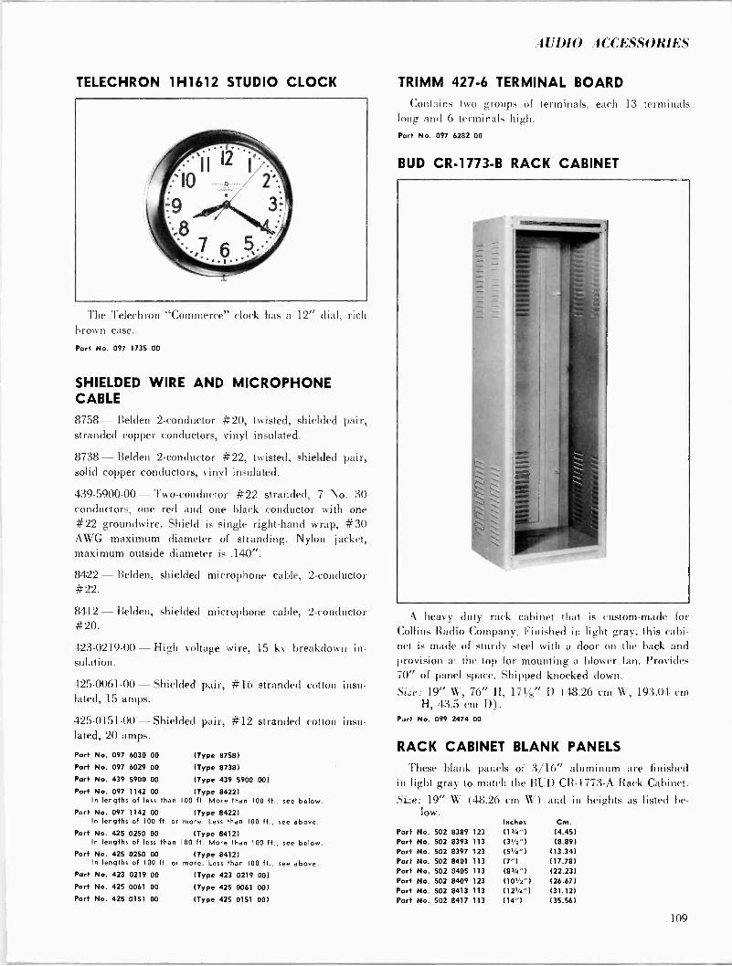
f UDIO ACCESSORIES
TELECHRON 1H1612 STUDIO CLOCK
The Telechron "Commerce" clock has a 12" dial. rich brown case.
Part No. 097 1735 00
SHIELDED WIRE AND MICROPHONE CABLE
8758 - Belden 2 -conductor #20, twisted, shielded pair, stranded copper conductors, vinyl insulated.
8738 - Belden 2 -conductor #22, twisted, shielded pair, solid copper conductors, vinyl insulated.
439-5900-00 - Two -conductor #22 stranded, 7 No. 30 conductors, one red and one black conductor with one #22 groundwire. Shield is single right-hand wrap, #30 AWG maximum diameter of stranding. Nylon jacket, maximum outside diameter is .140".
8422 - Belden, shielded microphone cable, 2 -conductor #22.
8412 - Belden, shielded microphone cable, 2 -conductor #20.
423-0219-00 - High voltage wire, 15 kv breakdown in- sulation.
425-0061-00 - Shielded pair, #16 stranded cotton insu- lated, 15 amps.
425-0151-00 - Shielded pair, #12 stranded cotton insu- lated, 20 amps.
Part No. 097 6030 00 (Type 8758)
Part No. 097 6029 00 (Type 8738)
Part No. 439 5900 00 (Type 439 5900 00)
Part No. 097 1142 00 (Type 8422) In lengths of less than 100 ft. More than 100 ft. , see below.
Part No. 097 1142 00 In lengths of 100 ft. or
Part No. 425 0250 00 In lengths of less than
Part No. 425 0250 00 In lengths of 100 ft. or
(Type 8422) more. Less than 100 ft.,
(Type 8412) 100 ft. More than 100 ft.
(Type 8412) more. Less than 100 ft.,
see above.
, see below.
see above. Part No. 423 0219 00 (Type 423 0219 00)
Part No. 425 0061 00 (Type 425 0061 00)
Part No. 425 0151 00 (Type 425 0151 00)
TRIMM 427-6 TERMINAL BOARD
Contains two groups of terminals, each 13 terminals long and 6 terminals high. Part No. 097 6282 00
BUD CR -1773-B RACK CABINET
A heavy duty rack cabinet that is custom-made for Collins Radio Company. Finished in light gray, this cabi- net is made of sturdy steel with a door on the back and provision at the top for mounting a blower fan. Provides 70" of panel space. Shipped knocked down.
Size: 19" W, 76" H, 171/s" D (48.26 cm W, 193.04 cm H. 43.5 cm D) .
Part No. 099 2474 00
RACK CABINET BLANK PANELS
These blank panels of 3/16" aluminum are finished in light gray to match the BUD CR -1773-A Rack Cabinet.
Size: 19" W (48.26 cm W) and in heights as listed be- low.
Inches Cm. Port No. 502 8389 123 (PA") (4.45) Part No. 502 8393 113 (3)/2") (8.89) Part No. 502 8397 123 (51/4") (13.34) Part No. 502 8401 113 (7") (17.78) Part No. 502 8405 113 (83/a") (22.23) Port No. 502 8409 123 (101/2") (26.67) Part No. 502 8413 113 (121/4") (31.12) Part No. 502 8417 113 (14") (35.56)
109
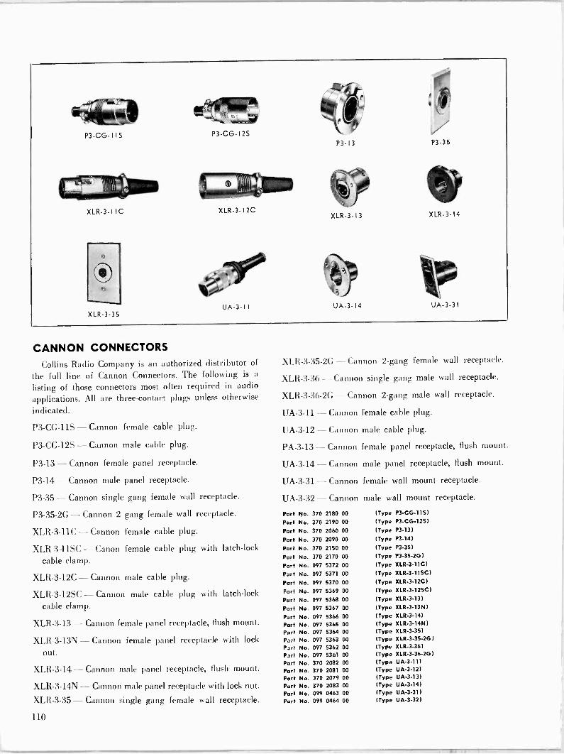
P3 -CG- 1 IS P3 -CG -12S
XLR-3-I IC XLR-3-I2C
XLR-3-35
CANNON CONNECTORS
Collins Radio Company is an authorized distributor of
the full line of Cannon Connectors. The following is a
listing of those connectors most often required in audio
applications. All are three -contact plugs unless otherwise
indicated.
P3 -CG -11S - Cannon female cable plug.
P3 -CG -12S - Cannon male cable plug.
P3-13 - Cannon female panel receptacle.
P3-14 - Cannon male panel receptacle.
P3-35 - Cannon single gang female wall receptacle.
P3 -35-2G - Cannon 2 gang female wall receptacle.
XLR-3-11C - Cannon female cable plug.
XLR 3 11SC - Canon female cable plug with latch -lock
cable clamp.
XLR-3-12C - Cannon male cable plug.
XLR-3-12SC - Cannon male cable plug with latch -lock
cable clamp.
XLR-3-13 - Cannon female panel receptacle, flush mount.
XLR-3-13N - Cannon female panel receptacle with lock
nut.
XLR-3-14 - Cannon male panel receptacle, flush mount.
XLR-3-14N - Cannon male panel receptacle with lock nut.
XLR-3-35 - Cannon single gang female wall receptacle.
P3-13 P3-35
XLR-3- 13 XLR-3-14
UA -3-14
XLR-3-35-2G - Cannon 2 -gang female wall receptacle.
XLR-3-36 - Cannon single gang male wall receptacle.
XLR-3-36.2G - Cannon 2 -gang male wall receptacle.
UA -3-11 - Cannon female cable plug.
UA -3-12 - Cannon male cable plug.
PA -3-13 - Cannon female panel receptacle, flush mount.
UA -3-14 - Cannon male panel receptacle, flush mount.
UA -3-31 - Cannon female wall mount receptacle.
UA -3-32 - Cannon male wall mount receptacle.
Part No. 370 2180 00 (Type P3 -CG -115)
Part No. 370 2190 00 (Type P3 -CG -125)
Port No. 370 2060 00 (Type P3-13)
Part No. 370 2090 00 (Type P3-14)
Par/ No. 370 2150 00 (Type P3-35)
Part No. 370 2170 00 (Type P3.35.2G(
Part No. 097 5372 00 (Type XLR-3-11C)
Port No. 097 5371 00 (Type XLR-3.115C)
Part No. 097 5370 00 (Type XLR-3-12C)
Fart No. 097 5369 00 (Type XLR-3.12SC)
Par/ No. 097 5368 00 (Type XLR-3-13)
Part No. 097 5367 00 (Type XLR-3-13N)
Part No. 097 5366 00 (Type XLR-3-14)
Part No. 097 5365 00 (Type XLR-3-14N)
Part No. 097 5364 00 (Type XLR-3-35)
Pa:t Mo. 097 5363 00 (Type XLR-3-35.2G)
Par) No. 097 5362 00 (Type XLR-3-36(
Part No. 097 5361 00 (Type XLR-3-36-2G)
Part No. 370 2082 00 (Type UA -3.11)
Par) No. 370 2081 00 (Type UA -3-12)
Fart No. 370 2079 00 (Type UA -3-13)
Part No. 370 2083 00 (Type UA -3-14)
Part No. 099 0463 00 (Type UA -3-31)
Part No. 099 0464 00 (Type UA -3-32)
110
I 1

RE.11OTE AUDIO
COLLINS 808A-1 REMOTE TURNTABLE -CONSOLE
A compact, completely transistorized portable unit, the three -channel 808A-1 is designed for quick, easy, high fidelity program origination in remote broadcasting. Ideal for promotion -type shows, the turntable -console offers complete facilities to feed program material into a tele- phone line to the broadcast station. The unit also will allow independent control of public address facilities and can be used to drive a remote amplifier such as the Col-
lins 212H-1. The 808-A-1 is especially suited for combination work
in a small announce booth; for schools where an economi- cal unit but complete facilities are needed; for use in conjunction with sound systems; and for standby studio facilities at the transmitter site in case of breakdown be-
tween the studio and transmitter. The 808A-1 eliminates the need for multiple equip-
ments. Once on location, the unit can be plugged in, con- nected to a remote line and it is ready for use. It can simultaneously combine the two self-contained turntable outputs with any one of three remote inputs. Built-in phono equalization meets RIAA standards. A VU meter indicates program level, and a headphone jack is pro- vided for program monitoring. Line terminals and micro- phone jacks are located on the back of the unit.
A bottom dust cover, easily removed, protects the low- er portions of the turntables, cabling and amplifiers. The preamplifiers attach to the control panel, which is remov-
able as a unit for servicing. Legs are detachable and self -
storing beneath the unit. The sturdy, modern -looking cabi- net is made of steel with a white and gray baked enamel finish. The panel and trim strips are brushed aluminum.
Controls on the panel include the following: and ex-
ternal input selector switch, which will select one of the external outputs of Mike 1, Mike 2 or NEMO; motor power switches which energize the turntable motors; three cue switches which are gauged to the fader control; three separate fader controls for the three inputs; master gain, which controls the over-all output signal; ac power switch, which is gauged to the public address gain; pub- lic address gain, which allows independent adjustment of the public address or other remote systems; headphone gain; and turntable shift levers for selection of proper turntable speed of 33, 45 or 78 rpm.
The remote amplifier, made up of six low level modules and one line amplifier module, uses eight General Electric 1175A low noise transistors and two Motorola 651 push- pull Class A -B transistors. Bias is stabilized over a wide temperature range by the use of a germanium diode. The turntable preamplifiers conform to NAB and RIAA specifications and feature a feedback design which offers a consistently stable performance.
Two Collins TT -200 Turntables with Rek-O-Kut S-320 pickup arms and General Electric sapphire cartridges are furnished with the 808A-1. Specially designed for radio
111
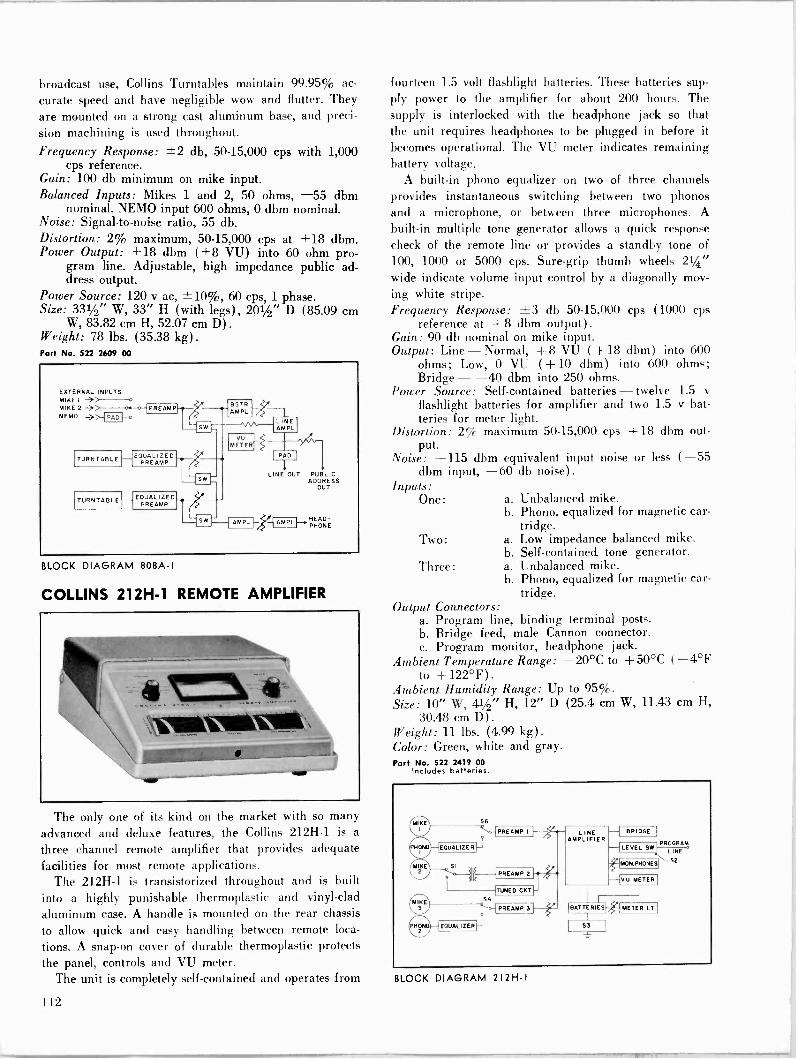
broadcast use, Collins Turntables maintain 99.95% ac-
curate speed and have negligible wow and flutter. They
are mounted on a strong cast aluminum base, and preci- sion machining is used throughout. Frequency Response: ±2 db, 50-15,000 cps with 1,000
cps reference. Gain: 100 db minimum on mike input. Balanced Inputs: Mikes 1 and 2, 50 ohms, -55 dbm
nominal. NEMO input 600 ohms, 0 dbm nominal. Noise: Signal-to-noise ratio, 55 db. Distortion: 2% maximum, 50-15,000 cps at +18 dbm. Power Output: +18 dbm (+8 VU) into 60 ohm pro-
gram line. Adjustable, high impedance public ad- dress output.
Power Source: 120 v ac, ±10%, 60 cps, 1 phase. Size: 331/2" W, 33" H (with legs) , 201/2" D (85.09 cm
W, 83.82 cm H, 52.07 cm D) .
Weight: 78 lbs. (35.38 kg) . Part No. 522 2609 00
EXTERNAL INPUTS
/
MIKE I
MIKE 2 -1--w-o-IPREAMP AMPL
NEMO -> ppp LINE AMPL
VU METER
EQUALIZED ---/5-- TURNTABLE PR EAMP
PAD
` sw LINE OUT PUBLIC
ADDRESS OUT
EQUALIZED TURNTABLE PR EAMP
SW AMPL PHONE -{AMPLI-+HEAD-
BLOCK DIAGRAM 808A -I
COLLINS 212H-1 REMOTE AMPLIFIER
The only one of its kind on the market with so many advanced and deluxe features, the Collins 212H-1 is a
three channel remote amplifier that provides adequate facilities for most remote applications.
The 212H-1 is transistorized throughout and is built into a highly punishable thermoplastic and vinyl -clad
aluminum case. A handle is mounted on the rear chassis
to allow quick and easy handling between remote loca-
tions. A snap -on cover of durable thermoplastic protects the panel, controls and VU meter.
The unit is completely self-contained and operates from
fourteen 1.5 volt flashlight batteries. These batteries sup- ply power to the amplifier for about 200 hours. The supply is interlocked with the headphone jack so that the unit requires headphones to be plugged in before it becomes operational. The VU meter indicates remaining battery voltage.
A built-in phono equalizer on two of three channels provides instantaneous switching between two phonos and a microphone, or between three microphones. A
built-in multiple tone generator allows a quick response check of the remote line or provides a standby tone of 100, 1000 or 5000 cps. Sure -grip thumb wheels 21/4" wide indicate volume input control by a diagonally mov- ing white stripe. Frequency Response: ±3 db 50-15,000 cps (1000 cps
reference at + 8 dbm output) .
Gain: 90 db nominal on mike input. Output: Line-Normal, +8 VU (+18 dbm) into 600
ohms; Low, 0 VU (+ 10 dbm) into 600 ohms; Bridge - -40 dbm into 250 ohms.
Power Source: Self-contained batteries - twelve 1.5 v flashlight batteries for amplifier and two 1.5 v bat- teries for meter light.
Distortion: 2% maximum 50-15,000 cps + 18 dbm out- put.
Noise: -115 dbm equivalent input noise or less (-55 dbm input, -60 db noise).
Inputs: One:
Two:
Three:
a. Unbalanced mike. b. Phono, equalized for magnetic car-
tridge. a. Low impedance balanced mike. b. Self-contained, tone generator. a. Unbalanced mike. b. Phono, equalized for magnetic car-
tridge. Output Connectors:
a. Program line, binding terminal posts. b. Bridge feed, male Cannon connector. c. Program monitor, headphone jack.
Ambient Temperature Range: -20°C to + 50°C (-4°F to +122°F).
Ambient Humidity Range: Up to 95%. Size: 10" W, 41/2" H, 12" D (25.4 cm W, 11.43 cm H,
30.48 cm D) .
Weight: 11 lbs. (4.99 kg) .
Color: Green, white and gray. Part No. 522 2419 00
Includes batteries.
PREAMP 2
LINE AMPLIFIER
-1 BRIDGE
LEVEL SW PROGRAM
LINE
MON.PHONES S2
-1VU METERI
11115= C1=1 53
BLOCK DIAGRAM 212H -I
112

REMOTE AUDIO
COLLINS 212Z-1 REMOTE AMPLIFIER
Weighing a total of 22 pounds including batteries and carrying case, the 212Z-1 offers full functions for remote
broadcasts. This transistorized remote amplifier mixes
inputs from up to four microphones, with program line
and communication line outputs as well as an auxiliary output for PA feed.
A power source of both 115 v ac and batteries assures uninterrupted service. Should the ac power fail, an auto-
matic changeover switches the 212Z-1 to battery power
and reverts when ac power is restored. A light on the panel indicates when the 212Z-1 operates on ac power. The self-contained batteries have a long life of about 75 hours.
The Collins 212Z-1 is attractively style - yet rugged and convenient to use. Housed in a Royalite carrying case, the 212Z-1 securely fastens to the bottom of the case. The 212Z-1 has a black and metallic blue -gray abrasion -resistant finish.
The four channel mixing circuit incorporated in the amplifier is designed to work with all microphones having a 30 to 600 ohm impedance. The output circuit matches a 600 ohm line. Provisions are made for two program lines and a telephone through the output switch.
Although simultaneous program feed and communica- tion cannot take place over a single line at the same time, the output switch allows rapid interchange between com- munication and the amplifier output on the same line.
The power supply is a shielded, full -wave unit with germanium diodes and multi -section filtering. A power interlock switch insures no battery drain when the unit is in its closed carrying case.
The Collins 212Z-1 Remote Amplifier is completely transistorized throughout. The tone oscillator, preampli-
fiers and interstage amplifiers use 2N422 hermetically -
sealed low noise transistors. The driver employs a 2N465
transistor. The output amplifier, with transformer coup-
ling on the input and output sides, has push-pull 2N44 transistors.
Since line levels are most easily set up by means of a
steady audio tone, the 212Z-1 includes a built-in audio tone oscillator as a standard feature.
One or two headphones may be plugged into the moni-
tor jacks. Where loudspeaker monitoring or feed for local public address is desired, the PA terminals are used. An isolated PA feed and an individual gain control allow
the operator to handle the program and simultaneously ride gain on the PA system. A multiple jack on the side permits two units to be used simultaneously and con-
trolled by one master gain control.
Frequency Response: ±1.5 db 50-15,000 cps.
Input: 4 channels selected by Daven step -type attenuators numbered to correspond with input plugs.
Input Impedance: 30-600 ohms. Gain: 90 db maximum. Noise Level: 55 db below normal output level.
Distortion: Less than 11/2% at +5 dbm. Power Output: Normal + 11 dbm; emergency + 16 dbm.
Output Impedance: 600 ohms (150 ohms available) .
Power Source: 115 v or 230 v ac 50/60 cps or self-con- tained batteries, such as one 4.5 v Burgess D-3 or Eveready 726, and two 223 v Eveready 763. Life of 22.5 v battery is approximately 75 hours; 4.5 v ap- proximately 90 hours. (Batteries not supplied with unit.)
Microphone Connections: 4 Cannon XL -3-13N.
Ambient Temperature Range: 0°-45°C. Ambient Humidity Range: Up to 95%. Size: 151/2" W, 61/2" H, 141/2"D (39.37 cm W, 16.51 cm
H, 36.83 cm D) .
Weight: 22 lbs. (9.98 kg) (with batteries). Part No. 522 0330 003
212Z-1 without batteries.
Port No. 015 0520 000 (Type 763) Two batteries required in addition to one Type 726 battery (below).
Part No. 015 0519 000 (Type 726) One battery required in addition to two Type 763 batteries (above).
PREAMPS
INPUT
2
115/230V 50/60n. AC POWER SUPPLY
E SWITCH ] RELAY
PROGRAM LINE MULTIPLE MONITOR MONITOR
2ND PREAMP OUTPUT
BOOSTER DRIVER
BATTERY SUPPLY
D AMPLIFIER
31 PAD Q ATTENUATOR r POTENIOMETER
METER
LINE I
LINE 2 TEL
PA
BLOCK DIAGRAM 212Z -I
113

MARTI REMOTE PICK-UP EQUIPMENT
Marti Remote Transmitter and Receiver provide qual- ity transmission of sports, spot news reports and inter- views on frequencies assigned for exclusive use by broad- casters. The unit is compact and light enough to be carried into stadiums and press boxes as easily as a multi- channel remote amplifier.
The audio quality of the Marti for music or voice trans- mission is guaranteed to be equal to or better than lines with coverage up to 40 miles radius depending upon the type and location of the transmitting and receiving antennas. The Marti Receiver is equipped with an auto- matic relay that operates an alarm system in the station to indicate a forthcoming broadcast.
The unit may legally be used instead of lines even where lines are available. Many stations, after installing the Marti system, have standing sponsorship of all their remote programs and have actually paid for the equip- ment in savings on line charges alone. The equipment also opens new program possibilities that are overlooked because of inconvenience in using other, cumbersome and less reliable means.
The Marti Transmitter is operated either by ac or batteries. Designed for continuous duty, the equipment meets the most stringent FCC requirements regarding bandwidth.
It is easily portable and lightweight and does not require frequent tuning. The transmitter and transistor- ized power supply and associated equipment are easily installed in a car for permanent and immediate use.
M-30B/TPS MOBILE TRANSMITTER
The M-30B/TPS is a 30 watt base station transmitter for communication with mobile units operating in the 152 to 172 megacycle range. The unit provides frequency stability of ± .0005% within a temperature range of minus 30 degrees C to plus 60 degrees C. The modulation characteristic is adjusted at the factory for ± 7.5 kc for 100% modulation at 1000 cycles. R. F. Output: 30 Watts, continuous Frequency: 152-172 megacycles
Crystal Multiplication: 36 Spurious Emission: Spurious Radiation attenuated at least
70 DB below carrier level. Harmonics suppressed at least 60 DB.
Frequency Stability: Plus, or minus 0.0005% Temperature Range: Minus 30 degrees C to Plus 60
degrees C. Modulation: 30 F3 Maximum (Normally adjusted for Plus
or Minus 10 Kcs. swing.) Audio Inputs: Two (2). Can be adjusted for either 150
ohms or 600 ohm input. Use of a 50, 150, or 250 microphone will work satisfactorily into the 150 ohm input.
Audio Input Level: Minus 70 DB. Audio Connectors: Cannon XLR-3-31. Power Requirements: 120 Volts AC or 12.6 Volts DC. Modulation Control: Push-pull Limiter. Noise Level of Transmitter: Better than Minus 45 DB. Overall Response With Matched Receiver: Plus or Minus
2 DB from 75 to 7500 cycles. Distortion in Transmitter: Less than 3%. Net Weight: 16 pounds. Dimensions: 14" wide, 10" long, and 7" high. Port No. 099 1572 000
MARTI MR -30/150 170 RECEIVER
The MR -30/150-170 receiver is used for pickup from a mobile station operating in the 150 to 174 megacycle range. The receiver is sensitive to 0.6 micro -volts or less for 20 db quieting, and is selective to -100 db at ± 32 kc; -6 db or less at ± 15 kc. Application: Remote Pickup. Frequency Range: 150 to 174 megacycles. Spurious Response: All spurious and image responses
attenuated at least 100 db. Overall Response: ±2 db, 60 to 7500 cps with matching
transmitter. Frequency Stability: ±0.0005% with crystal oven. Temperature Range: -40°C to +70°C. Audio Output: +8 VU at 600 ohms.
Metering: Signal strength and VU brought out to test Jacks. Visual metering optional.
Tube Complement: 15 required. 8 tube types. 6DS4 - 1st RF Amp. (Nuvistor) 6DS4 - 2nd RF Amp. (Nuvistor) 6DS4 - 1st Mixer (Nuvistor)
114
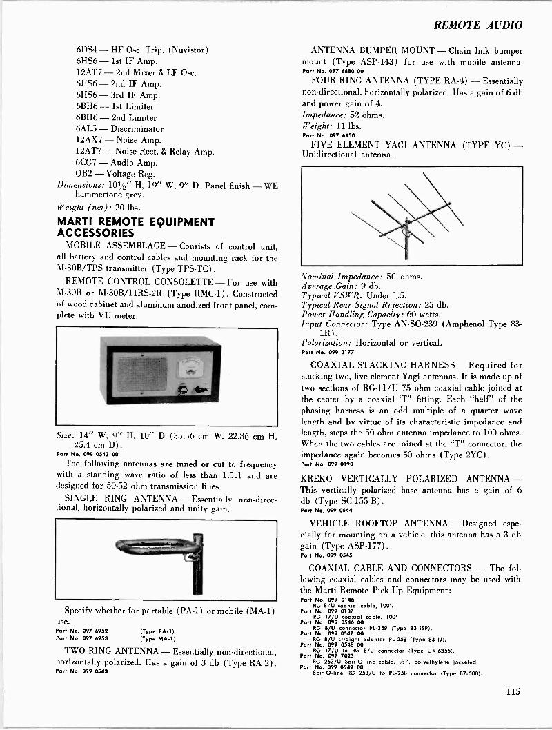
REMOTE AUDIO
6DS4 - HF Osc. Trip. (Nuvistor) 6HS6 - 1st IF Amp. 12AT7 - 2nd Mixer & LF Osc. 6HS6 - 2nd IF Amp. 6HS6 - 3rd IF Amp. 6BH6 - 1st Limiter 6BH6 - 2nd Limiter 6AL5 - Discriminator 12AX7 - Noise Amp. 12AT7 - Noise Rect. & Relay Amp. 6CG7 - Audio Amp. OB2 - Voltage Reg.
Dimensions: 101/2" H, 19" W, 9" D. Panel finish - WE hammertone grey.
Weight (net) : 20 lbs.
MARTI REMOTE EQUIPMENT ACCESSORIES
MOBILE ASSEMBLAGE - Consists of control unit, all battery and control cables and mounting rack for the M-30B/TPS transmitter (Type TPS-TC).
REMOTE CONTROL CONSOLETTE - For use with M -30B or M-30B/11RS-2R (Type RMC-1) . Constructed of wood cabinet and aluminum anodized front panel, com- plete with VU meter.
Size: 14" W, 9" H, 10" D (35.56 cm W, 22.86 cm Il. 25.4 cm D) .
Part No. 099 0542 00
The following antennas are tuned or cut to frequency with a standing wave ratio of less than 1.5:1 and are designed for 50-52 ohm transmission lines.
SINGLE RING ANTENNA - Essentially non -direc- tional, horizontally polarized and unity gain.
Specify whether for portable (PA -1) or mobile (MA -1) use. Part No. 097 6952 (Type PA -1) Part No. 097 6953 (Type MA -1)
TWO RING ANTENNA - Essentially non -directional, horizontally polarized. Has a gain of 3 db (Type RA -2). Part No. 099 0543
ANTENNA BUMPER MOUNT - Chain link bumper mount (Type ASP -143) for use with mobile antenna. Part No. 097 6880 00
FOUR RING ANTENNA (TYPE RA -4) - Essentially non -directional, horizontally polarized. Has a gain of 6 db and power gain of 4. Impedance: 52 ohms. Weight: 11 lbs. Part No. 097 6950
FIVE ELEMENT YAGI ANTENNA (TYPE YC) - Unidirectional antenna.
Nominal Impedance: 50 ohms. Average. Gain: 9 db. Typical VSWR: Under 1.5. Typical Rear Signal Rejection: 25 db. Power Handling Capacity: 60 watts. Input Connector: Type AN -SO -239 (Amphenol Type 83-
1R). Polarization: Horizontal or vertical. Part No. 099 0177
COAXIAL STACKING HARNESS - Required for stacking two, five element Yagi antennas. It is made up of two sections of RG -11/U 75 ohm coaxial cable joined at the center by a coaxial `T" fitting. Each "half" of the phasing harness is an odd multiple of a quarter wave length and by virtue of its characteristic impedance and length, steps the 50 ohm antenna impedance to 100 ohms. When the two cables are joined at the "T" connector, the impedance again becomes 50 ohms (Type 2YC). Port No. 099 0190
KREKO VERTICALLY POLARIZED ANTENNA - This vertically polarized base antenna has a gain of 6 db (Type SC -155-B). Part No. 099 0544
VEHICLE ROOFTOP ANTENNA - Designed espe- cially for mounting on a vehicle, this antenna has a 3 db gain (Type ASP -177). Part No. 099 0545
COAXIAL CABLE AND CONNECTORS - The fol- lowing coaxial cables and connectors may be used with the Marti Remote Pick -Up Equipment: Part No. 099 0146
RG 8/U coaxial cable, 100'. Part No. 099 0137
RG 17/U coaxial cable. 100' Part No. 099 0546 00
RG 8/U connector PL -259 (Type 83-ISP). Part No. 099 0547 00
RG 8/U straight adapter PL -258 (Type 83-IJ). Part No. 099 0548 00
RG 17/U to RG 8/U connector (Type GR -6355). Part No. 097 7023
RG 253/U Spir-O-line cable, 1/2", polyethylene jacketed Part No. 099 0549 00
Spir-O-line RG 253/U to PL -258 connector (Type 87-500).
115
Measuring, Monitoring, Remote Control
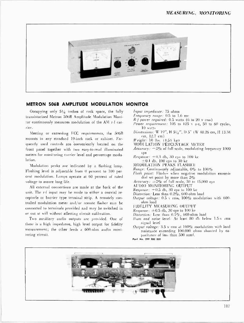
MEASURING, MONITORING
METRON 506B AMPLITUDE MODULATION MONITOR Occupying only 51/4 inches of rack space, the fully
transistorized Metron 506B Amplitude Modulation Moni-
tor continuously measures modulation of the AM r -f car- rier.
Meeting or exceeding FCC requirements, the 506B mounts in any standard 19 -inch rack or cabinet. Fre- quently used controls are 'conveniently located on the front panel together with two easy -to -read illuminated meters for monitoring carrier level and percentage modu- lation.
Modulation peaks are indicated by a flashing lamp. Flashing level is adjustable from 0 percent to 100 per- cent modulation. Lamps operate at 60 percent of rated voltage to assure long life.
All external connections are made at the back of the unit. The r -f input may be made to either a coaxial re-
ceptacle or barrier type terminal strip. A remotely con-
trolled modulation meter and/or remote Washer may be connected to terminals provided and may be switched in or out at will without affecting circuit calibration.
Two auxiliary audio outputs are provided. One of
these is a high impedance, high level output for fidelity measurement; the other feeds a 600 -ohm audio moni- toring circuit.
Input impedance: 75 ohms Frequency range: 0.5 to 1.6 me R-/ power required: 0.5 watts (6 to 20 v rms) Power requirement: 105 to 125 v a -c, 50 to 60 cycles,
10 watts Dimensions: W 19", H 51/4", D 5" (W 48.26 cm, H 13.34
cm, 12.7 cm) Weight: 10 lbs. (4.54 kg) MODULATION PERCENTAGE METER Accuracy: ±2% of full scale, modulating frequency 1000
cps Response: ±0.3 db, 30 cps to 100 kc
±0.1 db, 100 cps to 30 kc MODULATION PEAKS FLASHER Range: Continuously adjustable, 0% to 100% Flash point: Flashes when negative modulation exceeds
dial set point by more than 2% Accuracy: ±2% of full scale, 30 to 15,000 cps AUDIO MONITORING OUTPUT Response: ±0.5 db, 30 cps to 100 kc Distortion: Less than 0.2%, 600 -ohm load Output voltage: 0.5 v rms, 100% modulation with 600 -
ohm load FIDELITY MEASURING OUTPUT Response: ±0.5 db, 30 cps to 100 kc Distortion: Less than 0.1%, 600 -ohm load Hum and noise level: At least 80 db below 1.5-v rms
signal level Output voltage: 3.5 v rms at 100% modulation with load
resistance exceeding 100,000 ohms shunted by ca- pacitance of less than 500 mmf.
Part No. 099 300 000
117
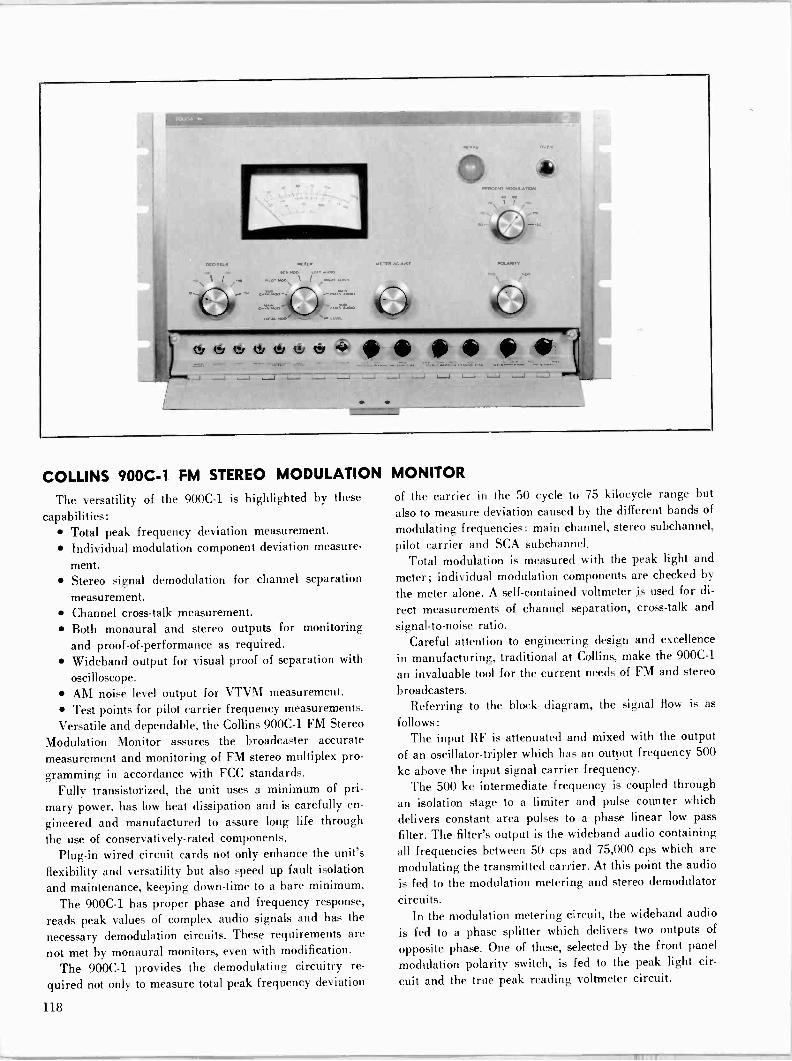
COLLINS 900C-1 FM STEREO MODULATION MONITOR
The versatility of the 900C-1 is highlighted by the-
capabilities: Total peak frequency deviation measurement. Individual modulation component deviation measure-
ment. Stereo signal demodulation for channel separation
measurement. Channel cross -talk measurement. Both monaural and stereo outputs for monitoring and proof -of -performance as required. Wideband output for visual proof of separation with
oscilloscope. AM noise level output for VTVM measurement. Test points for pilot carrier frequency measurements.
Versatile and dependable, the Collins 900C-1 FM Stereo
Modulation Monitor assures the broadcaster accurate measurement and monitoring of FM stereo multiplex pro-
gramming in accordance with FCC standards. Fully transistorized, the unit uses a minimum of pri-
mary power, has low heat dissipation and is carefully en-
gineered and manufactured to assure long life through
the use of conservatively -rated components. Plug-in wired circuit cards not only enhance the unit's
flexibility and versatility but also speed up fault isolation
and maintenance, keeping down -time to a bare minimum.
The 900C-1 has proper phase and frequency response,
reads peak values of complex audio signals and has the
necessary demodulation circuits. These requirements are
not met by monaural monitors, even with modification.
The 900C-1 provides the demodulating circuitry re-
quired not only to measure total peak frequency deviation
of the carrier in the 50 cycle to 75 kilocycle range but
also to measure deviation caused by the different bands of
modulating frequencies: main channel, stereo subchannel,
pilot carrier and SCA subchannel. Total modulation is measured with the peak light and
meter; individual modulation components are checked by
the meter alone. A self-contained voltmeter is used for di-
rect measurements of channel separation, cross -talk and
signal-to-noise ratio. Careful attention to engineering design and excellence
in manufacturing, traditional at Collins, make the 900C-1
an invaluable tool for the current needs of FM and stereo
broadcasters. Referring to the block diagram, the signal flow is as
follows: The input RF is attenuated and mixed with the output
of an oscillator -tripler which has an output frequency 500
kc above the input signal carrier frequency. The 500 kc intermediate frequency is coupled through
an isolation stage to a limiter and pulse counter which
delivers constant area pulses to a phase linear low pass
filter. The filter's output is the wideband audio containing all frequencies between 50 cps and 75,000 cps which are
modulating the transmitted carrier. At this point the audio
is fed to the modulation metering and stereo demodulator
circuits. In the modulation metering circuit, the wideband audio
is fed to a phase splitter which delivers two outputs of
opposite phase. One of these, selected by the front panel
modulation polarity switch, is fed to the peak light cir-
cuit and the true peak reading voltmeter circuit.
118

MEASURING, MONITORING
Switched filters in the audio path break up the total modulation into the four different bands: main channel, stereo subchannel, pilot carrier and SCA subchannel.
In the stereo demodulator circuit, the audio signal from the phase linear low pass filter has the 19 kc pilot carrier separated, doubled to 38 kc and amplified to a level cap- able of driving the switching diodes. The switch breaks the composite signal into left and right output signals and amplitude correction is made by cross -coupling left and right outputs. The two outputs are filtered to remove all frequencies above 15 kc and then are identically am- plified to provide left and right signals.
A built-in calibration circuit assures proper phasing of the regenerated 38 kc subcarrier as required for accurate stereo demodulation. MODULATION METER SECTION Meter Positions: Total modulation, main channel modu-
lation, stereo subchannel injection, pilot carrier mod- ulation, SCA subchannel injection.
Meter Range: 0%-133% for total, main and stereo sub - channel modulation. 0%-30% for pilot carrier and SCA subchannel injection.
Accuracy: 5% over entire scale. Meter Characteristics: Rise time, decay time and damp-
ing factor as prescribed by FCC for FM monaural monitors (all meter positions).
Frequency Response: ±0.5 db from 50-75,000 cps. Calibration: Self-contained calibrating signal source. External Meters: Provisions for adding series meter in
short line (100 foot maximum) or remote meter in telephone line (5000 ohm maximum loop resistance).
PEAK LIMIT INDICATOR LIGHT Range: Threshold adjustable from 50%-120% modula-
tion. Response: Will flash on modulation peaks of 20 millisec-
onds duration or greater. External Indicators: Provision included for external peak
limit indicator light. MONAURAL AUDIO SECTION Outputs: 0 dbm unbalanced (600 ohm flat or de-empha-
sized) . 10 v rms across 10,000 ohms (flat or de-em- phasized) .
Frequency Response: ±0.5 db from 50-15,000 cps or within 1.0 db of standard 75 microsecond de -em- phasis curve.
Distortion: 0.25% max. 50 cycles per second to 15 kc at 100% modulation.
Signal -to -Noise Ratio: 75 db. STEREOPHONIC AUDIO SECTION Outputs: 0 dbm unbalanced (600 ohms flat or de-empha-
sized). Distortion meter output: 10 v rms across 10,000 ohms unbalanced.
Frequency Response: ±1 db from 50-15,000 cps or within 1.0 db of standard 75 microsecond de -emphasis curve.
Distortion: .5% max. from 50-15,000 cps at 90% modu- lation.
Signal -to -Noise Ratio: 55 db on self-contained voltmeter. Channel Separation: 40 db from 50-15,000 cps. Read on
self-contained audio voltmeter. Channel Cross -Talk: 45 db. Read on self-contained audio
voltmeter. Stereophonic Subcarrier Suppression: 60 db. Read on self-
contained audio voltmeter. Pilot Carrier Phasing: Transmitter pilot carrier phasing
adjusted for proper 0 crossing after calibration of stereophonic subcarrier regeneration in monitor.
GENERAL RF Input: 4-10 v rms at 50 ohms. Input on rear of unit. Outputs:
Rear Chassis-Left Channel, Right Channel, Monaural, Remote Meter, Remote Peak Indicator, Wideband Output, IF (500 kc) Output for Frequency Meter, and 19 kc Output (for frequency measurement).
Front Panel - Wideband Output, Monaural Audio Output, Left Audio Output, Right Audio Output, Distortion-Measurement Output, 38 kc, 19 kc, and AM Noise Measurement Output.
Controls: Front Panel - Function Selector, Voltmeter Refer-
ence Adjust, Voltmeter Range Adjust, Peak Indi- cator Threshold Adjust, Modulation Polarity Se- lect.
Subpanel-Modulation Meter Calibrate Switch, Mod- ulation Meter Calibrate Adjust, Subcarrier Phase Calibrate Switch, Subcarrier Phase Calibrate Ad- just, De -emphasis Switch, RF Input Level Adjust, and Power On -Off.
Size: 19" W, 101/2" H, 13-25/32" D (48.26 cm W, 26.67 cm H, 33.02 cm D) .
Weight: 35 lbs. (15.88 kg) .
Primary Power: 120 v or 240 v ±10%, 50-60 cps, 50 watts.
Part No. 522 3275 000
POWER SUPPLY
LIMITERS G PULSE
COUNTER
AMPL
DE EMPHASIS
AMPL
WIDE SAND OUTPUT
LOW PASS FILTER
19KC AMPL
AMPL PRASE
SPLITTER
.04.IDOUGLER
REVERSING' SWITCH
STEREO DEN
LEFT
RIGHT
MONAURAL OUTPUT LEFT OUTPUT
RIGHT
TOTA L
MAIN rH 0-15 F KC
1
SUB 25 TRUE PEAK
READING KO VM
SCA 59-CTS
Y` K PEAK PI LOT IND
LIGHT
M DET G
DC AMPL
AUD 10 VM
CIRCUIT
BLOCK DIAGRAM 900C -I
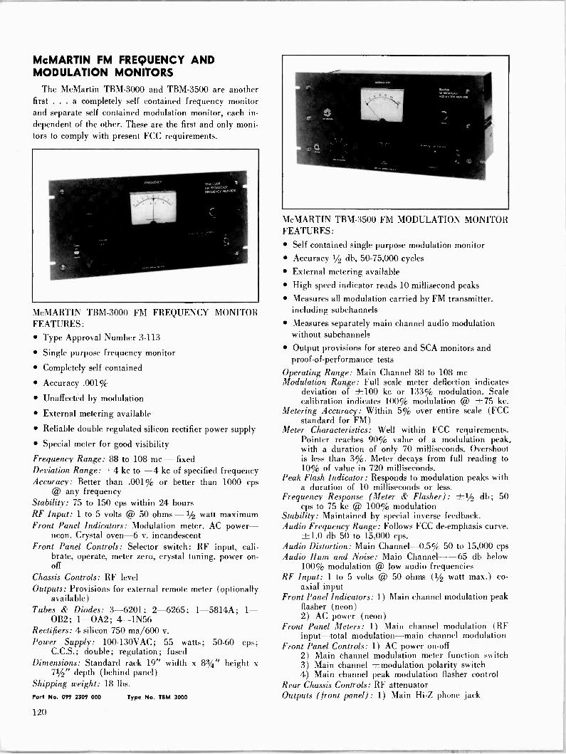
McMARTIN FM FREQUENCY AND MODULATION MONITORS
The McMartin TBM-3000 and TBM-3500 are another first ... a completely self contained frequency monitor and separate self contained modulation monitor, each in- dependent of the other. These are the first and only moni- tors to comply with present FCC requirements.
McMARTIN TBM-3000 FM FREQUENCY MONITOR FEATURES:
Type Approval Number 3-113
Single purpose frequency monitor
Completely self contained
Accuracy .001%
Unaffected by modulation
External metering available
Reliable double regulated silicon rectifier power supply
Special meter for good visibility
Frequency Range: 88 to 108 me - fixed Deviation Range: +4 kc to -4 kc of specified frequency Accuracy: Better than .001% or better than 1000 cps
@ any frequency Stability: 75 to 150 cps within 24 hours RF Input: 1 to 5 volts @ 50 ohms -1/2 watt maximum Front Panel Indicators: Modulation meter. AC power-
neon. Crystal oven -6 v. incandescent Front Panel Controls: Selector switch: RF input, cali-
brate, operate, meter zero, crystal tuning, power on - off
Chassis Controls: RF level Outputs: Provisions for external remote meter (optionally
available) Tubes & Diodes: 3-6201; 2-6265; 1-5814A; 1-
OB2; 1-0A2; 4-1N56 Rectifiers: 4 silicon 750 ma/600 v.
Power Supply: 100-130VAC; 55 watts; 50-60 cps; C.C.S.; double; regulation; fused
Dimensions: Standard rack 19" width x 83/4" height x 71/2" depth (behind panel)
Shipping weight: 18 lbs.
Part No. 099 2309 000 Type No. TOM 3000
MVIcMARTIN TBM-3500 FM MODULATION MONITOR FEATURES:
Self contained single purpose modulation monitor Accuracy 1/2 db, 50-75,000 cycles
External metering available
High speed indicator reads 10 millisecond peaks
Measures all modulation carried by FM transmitter, including subchannels
Measures separately main channel audio modulation without subchannels
Output provisions for stereo and SCA monitors and proof -of -performance tests
Operating Range: Main Channel 88 to 108 me Modulation Range: Full scale meter deflection indicates
deviation of ±100 kc or 133% modulation. Scale calibration indicates 100% modulation @ ±75 kc.
Metering Accuracy: Within 5% over entire scale (FCC standard for FM)
Meter Characteristics: Well within FCC requirements. Pointer reaches 90% value of a modulation peak, with a duration of only 70 milliseconds. Overshoot is less than 3%. Meter decays from full reading to 10% of value in 720 milliseconds.
Peak Flash Indicator: Responds to modulation peaks with a duration of 10 milliseconds or less.
Frequency Response (Meter & Flasher): cps to 75 kc @ 100% modulation
Stability: Maintained by special inverse feedback. Audio Frequency Range: Follows FCC de -emphasis curve.
±1.0 db 50 to 15,000 cps. Audio Distortion: Main Channel -0.5% 50 to 15,000 cps Audio Hum and Noise: Main Channel --65 db below
100% modulation @ low audio frequencies RF Input: 1 to 5 volts @ 50 ohms (1/2 watt max.) co-
axial input Front Panel Indicators: 1) Main channel modulation peak
flasher (neon) 2) AC power (neon)
Front Panel Meters: 1) Main channel modulation (RF input-total modulation-main channel modulation
Front Panel Controls: 1) AC power on -off 2) Main channel modulation meter function switch 3) Main channel ±modulation polarity switch 4) Main channel peak modulation flasher control
Rear Chassis Controls: RF attenuator Outputs (front panel) : 1) Main Hi -Z phone jack
±1/2 db; 50
120
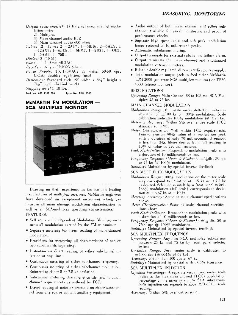
MEASURING, MONITORING
Outputs (rear chassis) : 1) External main channel modu- lation meter 2) Multiplex 3) Main channel audio Hi -Z 4) Main channel audio 600 ohms
Tubes: 12-Types: 2-12AT7; 1-6BH6; 2-6AK5; 1
-12AX7 ; 1-6BE6 ; 1-6EM7 ; 1-2D21; 1-0B2 ; 1- ÓAB4; 1-7581
Diodes: 3 (1N51) Fuse: 1-1 Amp SB-3AG Rectifiers: 4 type 1N2095 Silicon Power Supply: 100-130VAC; 55 watts; 50-60 cps;
C.C.S.; double; regulation; fused Dimension: Standard rack 19" width x 83/4" height x
71/2" depth (behind panel) Shipping weight: 18 lbs. Part No. 099 2308 000 Type No. IBM 3500
McMARTIN FM MODULATION - SCA MULTIPLEX MONITOR
Drawing on their experience as the nation's leading manufacturer of multiplex receivers, McMartin engineers have developed an exceptional instrument which can measure all main channel modulation characteristics as well as all SCA-multiplex operating characteristics. FEATURES:
Self contained independent Modulation Monitor, mea- sures all modulation carried by the FM transmitter. Separate metering for direct reading of main channel modulation.
Provisions for measuring all characteristics of one or two subchannels separately.
Instantaneous direct reading of either subchannel in- jection at any time.
Continuous metering of either subchannel frequency. Continuous metering of either subchannel modulation. Referred to either 5 or 7.5 kc deviation.
Subchannel metering characteristics identical to main channel requirements as outlined by FCC.
Direct reading of noise or crosstalk on either subchan- nel from any source without auxiliary equipment.
Audio output of both main channel and either sub - channel available for aural monitoring and proof of performance checks. Separate high speed main and sub peak modulation lamps respond to 10 millisecond peaks. Automatic subchannel muting. Output terminals for external subchannel failure alarm. Output terminals for main channel and subchannel modulation extension meters. Reliable double regulated silicon rectifier power supply. Total modulation output jack to feed either McMartin TBM-2000 (separate SCA-multiplex monitor) or TBM- 4500 (stereo monitor) .
SPECIFICATIONS Operating Range: Main Channel 88 to 108 mc. SCA Mul-
tiplex 25 to 75 kc.
MAIN CHANNEL MODULATION Modulation Range: Full scale meter deflection indicates
deviation of ±100 kc or 133% modulation. Scale calibration indicates 100% modulation @ ±75 kc.
Metering Accuracy: Within 5% over entire scale (FCC standard for FM).
Meter Characteristics: Well within FCC requirements. Pointer reaches 90% value of a modulation peak with a duration of only 70 milliseconds. Overshoot is less than 3%. Meter decays from full reading to 10% of value in 720 milliseconds.
Peak Flash Indicator: Responds to modulation peaks with a duration of 10 milliseconds or less.
Frequency Response (Meter & Flasher): ±1/2db; 50 cps to 75 kc @ 100% modulation.
Stability: Maintained by special inverse feedback.
SCA MULTIPLEX MODULATION Modulation Range: 100% modulation on the meter scale
may correspond to deviation of ±5 kc or ±7.5 kc as desired. Selection is made by a front panel switch. 133% modulation (full scale) corresponds to devia- tion of ±6.67 kc or ±10 kc.
Metering Accuracy: Same as main channel specifications above.
Meter Characteristics: Same as main channel specifica- tions above.
Peak Flash Indicator: Responds to modulation peaks with a duration of 10 milliseconds or less.
Frequency Response (Meter & Flasher): +1/2 db; 50 to 7500 cps @ 100% modulation.
Stability: Maintained by special inverse feedback.
SCA MULTIPLEX FREQUENCY Operating Range: Any two SCA multiplex subcarriers
between 25 kc and 75 kc by front panel selector switch.
Deviation Range: Zero center scale is calibrated to ±4000 cps (±.004% of 67 kc) .
Accuracy: Better than 100 cps at 67 kc. Stability: Maintained by crystal with .005% tolerance.
SCA MULTIPLEX INJECTION Injection Percentage: A separate circuit and meter scale
indicates the maximum allowed (FCC) modulation percentage of the main carrier by SCA subcarriers. 30% injection corresponds to about 2/3 of full scale reading.
Accuracy: Within 5% over entire scale.
121
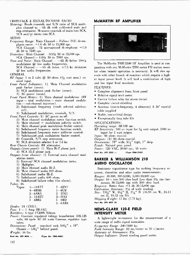
CROSSTALK & SIGNAL-TO-NOISE RATIO Metering: Reads crosstalk and S/N ratio of SCA multi-
plex channel to -65 db with calibrated scale and step attenuator. Measures crosstalk of main into SCA, SCA and/or stereo into SCA.
AUDIO Frequency Range: Main Channel - Follows FCC de -em-
phasis curve. ±1.0 db 50 to 15,000 cps. SCA Channel - 75 microsecond de -emphasis ±1.0 db 50 to 7500 cps.
Distortion: Main Channel - 0.5% 50 to 15,000 cps. SCA Channel - 1.0% 50 to 7500 cps.
Hum and Noise: Main Channel - -65 db below 100( modulation @ low audio frequencies. SCA Channel - -65 db below ±7.5 kc deviation @ low audio frequencies.
GENERAL RF Input: 1 to 5 volts @ 50 ohms (1/2 watt max.) co-
axial input. Front Panel Indicators: 1) Main Channel modulation
peak flasher (neon). 2) SCA modulation peak flasher (neon). 3) AC power (neon).
Front Panel Meters: 1) Main channel modulation (RF input - total modulation - main channel modula- tion - sub -channel injection) .
2) Subchannel frequency (reads selected subchan- nel)
3) Subchannel modulation, crosstalk, S/N. Front Panel Controls: 1) AC power on -off.
2) Main channel modulation meter function switch. 3) Main channel ± modulation polarity switch. 4) Main channel peak modulation flasher control. 5) Subchannel frequency meter function switch. 6) Subchannel frequency meter calibrate control. 7) Subchannel peak modulation flasher control. 8) Crosstalk, S/N step attenuator. 9) SCA deviation selector 5 or 7.5 kc.
Rear Chassis Controls: RF attenuator. Outputs (front panel) : 1) Main Hi -Z phone jack.
2) SCA Hi -Z phone jack. Outputs (rear chassis) : 1) External main channel mod-
ulation meter. 2) External SCA channel modulation meter. 3) Multiplex. 4) Main channel audio Hi -Z. 5) Main channel audio 600 ohms. 6) Subchannel audio Hi -Z. 7) Subchannel audio 600 ohms. 8) Subchannel failure relay (for alarm).
Tubes: 24. Types: 4-12AT7
4- 6BH6 2-6AK5 3-12AU7 1- 6BE6
1- 6SN7 1-6U8 2-2D21 2-0A2 1-0B2 2- 6AB4
Diodes: 14 (1N51). Fuse: 1-1 Amp SB-3AG. Rectifiers: 4 type 1N2095 Silicon. Power: Constant regulated voltage transformer 105-125
volts, 60 cycle AC 65 watts Gaseous regulator type tubes.
Dimensions: Panel - standard rack 103/4" x 19". Chassis -131/2" behind panel.
Weight: 34 lbs. Port No. 099 0824 - (Type No. TBM-4000)
McMARTIN RF AMPLIFIER
The McMartin TBM-2500 RF Amplifier is used in con junction with any McMartin TBM series FM station moni tor when remote operation is necessary. It will also op erate with other brands of monitors which require a high er input power level. It will feed a combination of high and low input level monitors.
FEATURES: Complete alignment from front panel Relative signal level meter Carrier failure relay for alarm circuit Complete circuit shielding Antenna (cut -to -frequency, 4 elements) & 50' coaxial cable supplied Stable, non -critical design Exceptionally long tube life
SPECIFICATIONS: Operating range: 88-108 mc. RF Sensitivity: 300 uy input for 1/2 watt output. 1000
for 2 watt output. Input: 50 ohms coaxial. Outputs: (2) 50 ohms coaxial. Dimensions: 19" wide, 51/4" high, 7" deep. Finish: Natural gray panel. Power: 120 VAC, 50-60 cps, 45 watts. Pori No. 099 2502 - (Type TOM -2500)
BARKER & WILLIAMSON 210 AUDIO OSCILLATOR
Resistance capacitance type for making sponse, distortion and other audio measure Ranges: 30-300, 300-3,000, 3,000-30,000 c Output: 10 v into 500 ohm load. Less than
monies 30-15,000 cps with 500 ohm Response: Better than ±1 db 30-15,000 Calibration Accuracy: 3% of scale reading Size: 133/4" W, 91/2" H, 71/4" D (34.93
cm H, 18.42 cm D). Shipping Weight: 17 lbs. (7.71 kg). Part No. 099 0827 00
frequency re- ments.
ps. 1 % rms har - load.
cps.
cm W, 24.13
NEMS-CLARK 120-E FIELD INTENSITY METER
A lightweight instrument for the measurement wide range of radio signal intensities. Frequency Range: 540-1600 kc. Field Intensity Range: 10 my/meter to 10 v/meter. Accuracy of Attenuators: 2%. Output Indicator: Direct reading panel meter.
of a
122
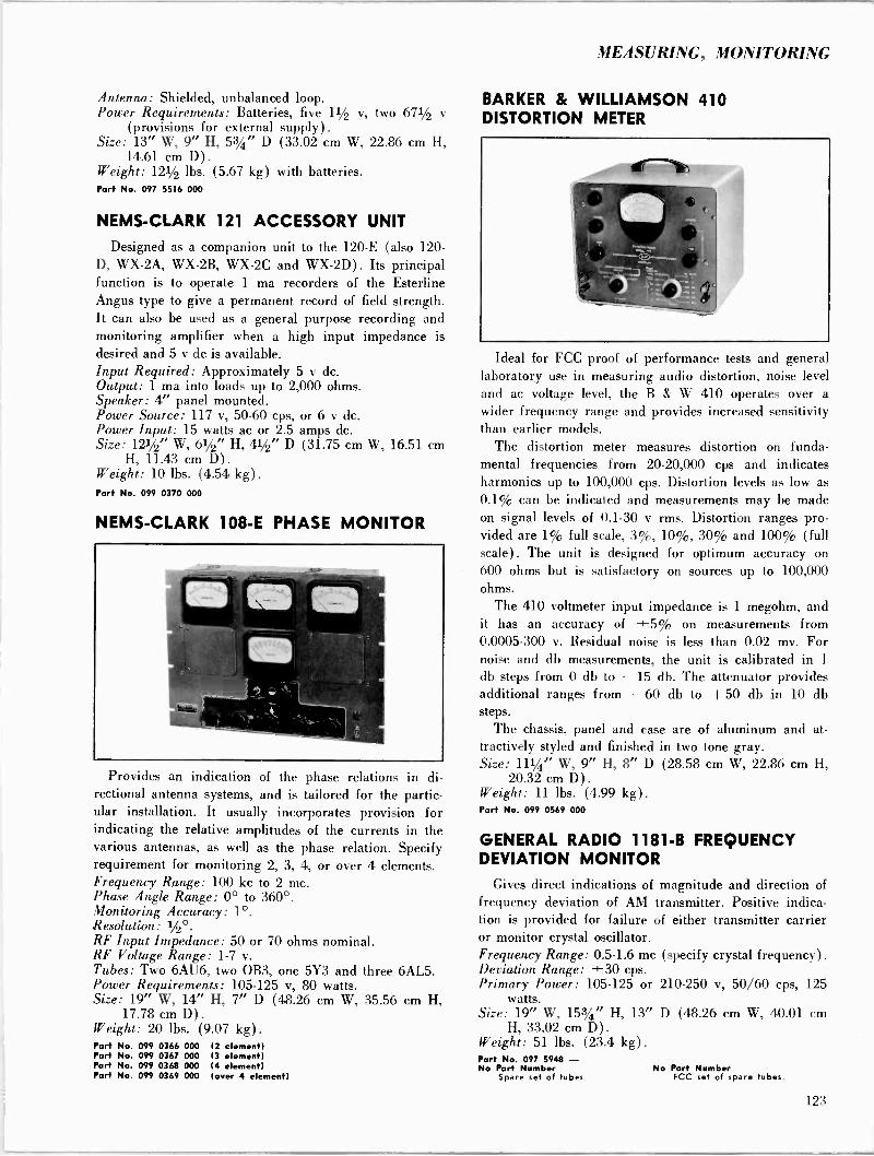
MEASURING, MONITORING
Antenna: Shielded, unbalanced loop. Power Requirements: Batteries, five 11/2 v, two 671/2 V
(provisions for external supply). Size: 13" W, 9" H, 53/4" D (33.02 cm W, 22.86 cm H,
14.61 cm D) .
Weight: 121/2 lbs. (5.67 kg) with batteries. Port No. 097 5516 000
NEMS-CLARK 121 ACCESSORY UNIT
Designed as a companion unit to the 120-E (also 120- D, WX-2A, WX-2B, WX-2C and WX-2D) . Its principal function is to operate 1 ma recorders of the Esterline Angus type to give a permanent record of field strength. It can also be used as a general purpose recording and monitoring amplifier when a high input impedance is desired and 5 v dc is available. Input Required: Approximately 5 v dc. Output: 1 ma into loads up to 2,000 ohms. Speaker: 4" panel mounted. Power Source: 117 v, 50.60 cps, or 6 v dc. Power Input: 15 watts ac or 2.5 amps dc. Size: 121/2" W, 61/2" H, 41/2" D (31.75 cm W, 16.51 cm
H, 11.43 cm D). Weight: 10 lbs. (4.54 kg) .
Port No. 099 0370 000
NEMS-CLARK 108-E PHASE MONITOR
Provides an indication of the phase relations in di- rectional antenna systems, and is tailored for the partic- ular installation. It usually incorporates provision for indicating the relative amplitudes of the currents in the various antennas, as well as the phase relation. Specify requirement for monitoring 2, 3, 4, or over 4 elements. Frequency Range: 100 kc to 2 mc. Phase Angle Range: 0° to 360°. Monitoring Accuracy: 1°. Resolution: 1/2°. RF Input Impedance: 50 or 70 ohms nominal. RF Voltage Range: 1-7 v. Tubes: Two 6AU6, two OB3, one 5Y3 and three 6AL5. Power Requirements: 105-125 v, 80 watts. Size: 19" W, 14" H, 7" D (48.26 cm W, 35.56 cm H,
17.78 cm D). Weight: 20 lb,. (9.07 kg) .
Part No. 099 0366 000 (2 element) Port No. 099 0367 000 (3 element) Port No. 099 0368 000 (4 element) Part No. 099 0369 000 (over 4 element)
BARKER & WILLIAMSON 410 DISTORTION METER
Ideal for FCC proof of performance tests and general laboratory use in measuring audio distortion, noise level and ac voltage level, the B & W 410 operates over a wider frequency range and provides increased sensitivity than earlier models.
The distortion meter measures distortion on funda- mental frequencies from 20-20,000 cps and indicates harmonics up to 100,000 cps. Distortion levels as low as 0.1% can be indicated and measurements may be made on signal levels of 0.1-30 v rms. Distortion ranges pro- vided are 1% full scale, 3%, 10%, 30% and 100% (full scale). The unit is designed for optimum accuracy on 600 ohms but is satisfactory on sources up to 100,000 ohms.
The 410 voltmeter input impedance is 1 megohm, and it has an accuracy of ±5% on measurements from 0.0005-300 v. Residual noise is less than 0.02 mv. For noise and db measurements, the unit is calibrated in 1
db steps from 0 db to -15 db. The attenuator provides additional ranges from -60 db to -- 50 db in 10 db steps.
The chassis, panel and case are of aluminum and at- tractively styled and finished in two tone gray. Size: 111/4" W, 9" H, 8" D (28.58 cm W, 22.86 cm H,
20.32 cm D) .
Weight: 11 lbs. (4.99 kg) .
Part No. 099 0569 000
GENERAL RADIO 1181-B FREQUENCY DEVIATION MONITOR
Gives direct indications of magnitude and direction of frequency deviation of AM transmitter. Positive indica- tion is provided for failure of either transmitter carrier or monitor crystal oscillator. Frequency Range: 0.5-1.6 mc (specify crystal frequency) .
Deviation Range: ±30 cps. Primary Power: 105-125 or 210-250 v, 50/60 cps, 125
watts. Size: 19" W, 153/4" H, 13" D (48.26 cm W, 40.01 cm
H, 33.02 cm D). Weight: 51 lbs. (23.4 kg) .
Part No. 097 5948 - No Part Number No Part Number
Spare set of tubes. FCC set of spare tubes.
123
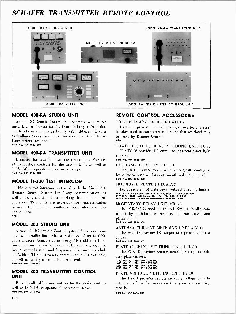
SCHAFER TRANSMITTER REMOTE CONTROL
MODEL 400 -RA STUDIO UNIT
---- W ((. . f'
O6C.®c90000G ococcAOC o 0
11111 s
MODEL TI -300 TEST INTERCOM
MODEL 300 STUDIO UNIT
MODEL 400 -RA TRANSMITTER UNIT
.. Y J J J
, Y Y u Y d 0
M (i
6i U EJ O A© A (J t> 0®
MODEL 300 TRANSMITTER CONTROL UNIT
MODEL 400 -RA STUDIO UNIT An all DC Remote Control that operates on any two
metallic lines (lowest tariff). Controls forty (40) differ- ent functions and meters twenty (20) different circuits and allows 2 -way telephone conversations at all times. Four meters included. Part No. 099 1518 000
MODEL 400 -RA TRANSMITTER UNIT Deigned for location near the transmitter. Provides
all calibration controls for the Studio Unit, as well as 110V AC to operate all accessory relays. Part No. 099 1519 000
MODEL TI -300 TEST INTERCOM This is a test intercom unit used with the Model 300
Remote Control System for 2 -way communication, as well as being a test unit for checking the remote control operation. Two units are necessary for communication between studio and transmitter without additional tele- phone lines. NPN
MODEL 300 STUDIO UNIT A new all DC Remote Control system that operates on
any two metallic lines with a resistance of up to 6000 ohms or more. Controls up to twenty (20) different func- tions and meters up to eleven (11) different circuits, including modulation and frequency. Five meters includ- ed. With a TI -300, two-way communication is available, as well as having a test unit at each end. Part No. 597 0409 000
MODEL 300 TRANSMITTER CONTROL UNIT
Provides all calibration controls for the studio unit, as well as 48 V DC to operate all accessory relays. Part No. 597 0410 000
REMOTE CONTROL ACCESSORIES
POR -1 PRIMARY OVERLOAD RELAY Parallels present manual primary overload circuit
breaker used in some transmitters, so that overload may be reset by Remote Control. NPN
TOWER LIGHT CURRENT METERING UNIT TC -25 The TC -25 provides DC output to represent tower light
current. Part No. 099 1521 000
LATCHING RELAY UNIT LR -1-C The LR -1-C is used to control circuits locally controlled
by switches, such as filaments on -off and plates on -off. Part No. 099 1520 000
MOTORIZED PLATE RHEOSTAT For adjustment of plate power without affecting tuning.
MPR-2 For 250 or 500 watt transmitter. Part No. 099 1544 000 MPR-3 For 1000 watt transmitter. Part No. 099 1545 000 MPR-4 For over 1 Kilowatt transmitter. Part No. NPN
MOMENTARY RELAY UNIT MR -2-C
The MR -2-C is used to control circuits locally con- trolled by push -buttons, such as filaments on -off and plates on -off. Part No. 097 6781 000
ANTENNA CURRENT METERING UNIT AC -100 The AC -100 provides DC output to represent antenna
current. Part No. 097 7581 000
PLATE CURRENT METERING UNIT PCK-10 The PCK-10 provides remote metering voltage to indi-
cate plate current. 300 MA Part No. 099 1538 000 600 MA Part No. 099 1539 000
1200 MA Port No. 099 1540 000 2400 MA Part No. 097 6663 000
PLATE VOLTAGE METERING UNIT PV -10
The PV -10 provides remote metering voltage to indi- cate plate voltage for connection to any one mil metering circuit. Part No. 097 6664 000
124

STL MICROWAVE
COLLINS STL MICROWAVE SYSTEMS
As a part of its Universal Microwave Group, Collins offers STL systems for the broadcast industry. These sys- tems are part of a broad, flexible, transistorized product line.
Collins Universal Microwave Group (U/M/G) equip- ment provides high performance on short-, medium-, and long -haul video relay applications for operation in the 6875- to 7125 -mc STL band. The U/M/G offers a choice of 1 -watt or 5 -watt output power and remodulating or heterodyne repeaters in a compatible integrated family of fully transistorized* microwave radio products. Most basic and accessory modules are identical to minimize training and spares provisioning in a system of mixed power requirements. Short- to medium -length system per- formance requirements are met with 1 -watt remodulating equipment. Extra long paths are possible using 5 -watt remodulating equipment, while 5 -watt i -f heterodyne re- peaters are available for long -haul systems. IF heterodyne repeaters eliminate the waveform distortion generated by the extra modulation step in remodulating type repeaters. Simplex (one-way) or duplex operation is available in non -standby or hot -standby configurations.
MW -408A: 1 -watt (+30 dbm) power output, Terminal or Remodulating Repeater Application.
MW -409A: 5 -watt (+37 dbm) power output, Terminal or Remodulating Repeater Application.
MW -409B: 5 -watt (+37 dbm) power output, IF Hetero- dyne Repeater Application.
FEATURES
Full transistorization* for maximum reliability / IF het- erodyne or remodulating repeaters / High frequency serv- ice channel and fault alarm available / U/M/G module interchangeability reduces spares program and training / Long -life TWT's with low-cost replacement envelope on 5 -watt transmitters / Nonstandby or hot -standby trans- mitter operation / Economical 24-vdc basic powering with 48-vdc or a -c options available / Simplex (one-way) or duplex operation / Ample built-in metering facilities / Standby systems use power splitters and optional com- biners on receivers for maximum reliability / Tempera- ture stabilization of all klystrons.
*Except for Klystrons and TWT's
125
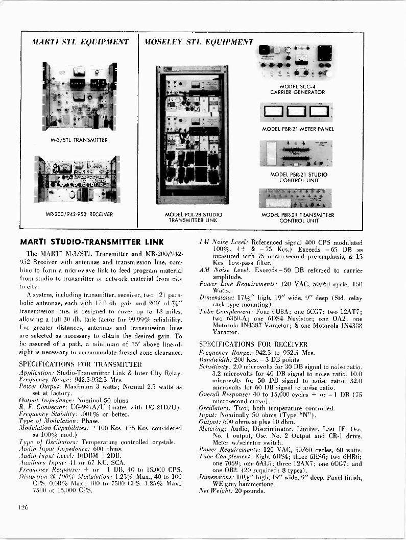
MARTI STL EQUIPMENT
M-3/STL TRANSMITTER
eLbJ:- V V
i-1 ,. o.9e0 .utïlii'
MR -200;'942-952 RECEIVER
MOSELEY STL EQUIPMENT
MODEL PCL-2B STUDIO TRANSMITTER LINK
i 1 ®3
MODEL SCG-4 CARRIER GENERATOR
MODEL PBR-21 METER PANEL
, a
-f=j- ii®t__ MODEL PBR-21 STUDIO
CONTROL UNIT
2-4 c e zee r 4 c w a w w
) b' s MODEL PBR-21 TRANSMITTER
CONTROL UNIT
MARTI STUDIO -TRANSMITTER LINK The MARTI M-3/STL Transmitter and MR -200/942-
952 Receiver with antennas and transmission line, com- bine to form a microwave link to feed program material from studio to transmitter or network material from city to city.
A system, including transmitter, receiver, two (2) para- bolic antennas, each with 17.0 db. gain and 200' of 7/g" transmission line, is designed to cover up to 18 miles, allowing a full 30 db. fade factor for 99.99% reliability. For greater distances, antennas and transmission lines are selected as necessary to obtain the desired gain. To be assured of a path, a minimum of 75' above line -of - sight is necessary to accommodate fresnel zone clearance.
SPECIFICATIONS FOR TRANSMITTER Application: Studio -Transmitter Link & Inter City Relay. Frequency Range: 942.5-952.5 Mcs. Power Output: Maximum 3 watts; Normal 2.5 watts as
set at factory. Output Impedance: Nominal 50 ohms. R. F. Connector: UG-997A/U (mates with UG-21D/U). Frequency Stability: .001% or better. Type of Modulation: Phase. Modulation Capabilities: ±100 Kcs. (75 Kcs. considered
as 100% mod.) Type of Oscillators: Temperature controlled crystals. Audio Input Impedance: 600 ohms. Audio Input Level: 10DBM ±2DB. Auxiliary Input: 41 or 67 KC. SCA. Frequency Response: + or - 1 DB, 40 to 15,000 CPS. Distortion @ 100% Modulation: 1.25% Max., 40 to 100
CPS. 0.08% Max., 100 to 7500 CPS. 1.25% Max., 7500 of 15,000 CPS.
FM Noise Level: Referenced signal 400 CPS modulated 100%. (+ & - 75 Kcs.) Exceeds -65 DB as measured with 75 micro -second pre -emphasis, & 15 Kcs. low-pass filter.
AM Noise Level: Exceeds - 50 DB referred to carrier amplitude.
Power Line Requirements: 120 VAC, 50/60 cycle, 150 Watts.
Dimensions: 171/2" high, 19" wide, 9" deep (Std. relay rack type mounting).
Tube Complement: Four 6U8A; one 6CG7; two 12AT7; two 6360-A; one 6DS4 Nuvistor; one 0A2; one Motorola IN4387 Varactor; & one Motorola IN4388 Varactor.
SPECIFICATIONS FOR RECEIVER Frequency Range: 942.5 to 952.5 Mcs. Bandwidth: 200 Kcs. -3 DB points. Sensitivity: 2.0 microvolts for 30 DB signal to noise ratio.
3.2 microvolts for 40 DB signal to noise ratio. 10.0 microvolts for 50 DB signal to noise ratio. 32.0 microvolts for 60 DB signal to noise ratio.
Overall Response: 40 to 15,000 cycles + or - 1 DB (75 microsecond curve).
Oscillators: Two; both temperature controlled. Input: Nominally 50 ohms (Type "N"). Output: 600 ohms at plus 10 dbm. Metering: Audio, Discriminator, Limiter, Last IF, Osc.
No. 1 output, Ose. No. 2 Output and CR -1 drive. Meter w/selector switch.
Power Requirements: 120 VAC, 50/60 cycles, 60 watts. Tube Complement: Eight 6DS4; three 6HS6; two 6HB6;
one 7059; one 6AL5; three 12AX7; one 6CG7; and one OB2. (20 required; 8 types).
Dimensions: 101/2" high, 19" wide, 9" deep. Panel finish, WE grey hammertone.
Net Weight: 20 pounds.
126
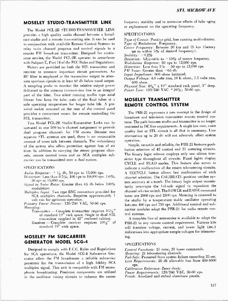
STL MICROWAVE
MOSELEY STUDIO -TRANSMITTER LINK
The Model PCL-2B STUDIO -TRANSMITTER LINK provides a high quality audio channel between a broad- cast studio and a remote transmitting site. It can be used in conjunction with available Remote Control Systems to
relay main channel program and control signals to a
remote FM broadcast transmitter. Designed for contin- uous service, the Model PCL-2B operates in accordance with Subpart E, Part 74 of the FCC Rules and Regulations.
Meters are provided on both the STL transmitter and receiver to measure important circuit parameters. An
RF filter is employed at the transmitter output to atten-
uate spurious signals to at least 60 db below rated output. A sampling probe to monitor the relative output power delivered to the antenna transmission line is an integral part of the filter. Two silent running muffin type axial blower fans keep the tube seals of the final tubes at a
safe operating temperature for longer tube life. A pre - wired socket mounted on the rear of the control panel provides a convenient means for remote controlling the STL transmitter.
Two Model PCL-2B Studio -Transmitter Links can be
operated in one 500 kc/s channel assignment to provide dual program channels for FM stereo. Because two
separate STL systems are used, there is no measurable amount of cross talk between channels. The redundancy of the system also offers protection against loss of air time. In addition to carrying the stereo program chan- nels, remote control tones and an SCA multiplex sub -
carrier can be transmitted over a dual system.
SPECIFICATIONS
Audio Response: ± 1/2 db, 50 cps to 15,000 cps. Distortion: Less than 0.5%, 100 cps to 10,000 cps. 1.0%,
50 cps to 15,000 cps. Signal to Noise Ratio: Greater than 65 db below 100%
modulation. Multiplex Input: Two type BNC connectors provided for
SCA multiplex channels. Requires approximately 1
volt rms for optimum operation. Primary Power Source: 120/240 VAC, 50-60 cps. Mounting:
Transmitter - Complete transmitter requires 153/4" of standard 19" rack space. Single or dual STL transmitter supplied in 42" enclosed cabinet.
Receiver - Complete receiver requires 101/2" of standard 19" rack space.
MOSELEY FM SUBCARRIER GENERATOR MODEL SCG-4
Designed to comply with F.C.C. Rules and Regulations for SCA operations, the Model SCG-4 Subcarrier Gen-
erator oilers the FM broadcaster a reliable subcarrier generator for the transmission of a high fidelity SCA
multiplex signal. This unit is compatible with FM stereo- phonic broadcasting. Precision components are utilized in the oscillator timing circuits to enhance the center
frequency stability and to minimize effects of tube aging or replacement on the operating frequency.
SPECIFICATIONS
Type of Circuit: Positive grid, free running multivibrator. Type of Modulation: Frequency. Center Frequency: Between 20 kcs and 75 kcs (factory
set to within 5% of desired frequency). Stability: ±0.2% Deviation: Adjustable to ±10% of center frequency. Modulation Response: 50 cps to 12,000 cps. Distortion: Less than 1% - 50 cps to 12,000 cps. FM Noise: Greater than -65 db. Input Impedance: 600 ohms balanced. Output Voltage: 4.0 volts rms, 10 K ohms; 1.5 volts rms,
600 ohms. Physical Size: 83/4" x 19" standard rack panel, 3" deep. Power Line: 120/240 VAC ±10%; 50-60 cps.
MOSELEY TRANSMITTER REMOTE CONTROL SYSTEM
The PBR-21 represents a new concept in the design of
broadcast and television transmitter remote control sys-
tems. The path between studio and transmitter is no longer
restricted to DC line requirements. A single low cost, voice
quality line or STL circuit is all that is necessary. Line
attenuation up to 20 db will not adversely affect system
operation. Simple, versatile and reliable, the PBR-21 features push-
button selection of 42 control and 21 metering circuits. The binary logic scheme employs only one silicon tran- sistor type throughout all circuits. Panel lights display
CYCLE and READ modes. This feature also serves to
indicate a malfunction of the return telemetering circuits.
A RECYCLE button allows fast confirmation of each
channel selection. The CALIBRATE position verifies sys-
tem accuracy at a touch. The binary logic output momen-
tarily interrupts the fail-safe signal to reposition the
channel selector switch. The LOWER and RAISE command
tones are 2000 cps and 2500 cps. Metering is returned to
the studio by a temperature stable oscillator operating between 400 cps and 750 cps. Additional control and sub -
carrier modules adapt the PBR-21 for radio remote con-
trol systems. A complete line of accessories is available to adapt the
PBR-21 to any remote control requirement. Various kits will translate voltage, current, and tower light (etc.) indications into appropriate sample voltages for telemeter- ing.
SPECIFICATIONS
Control Functions: 21 raise, 21 lower commands. Metering: 21 telemetering channels. Fail -Safe: Protected from system failure exceeding 25 sec. Line Requirements: 20 db allowable loss from 400-3000
cps. Calibration Reference: Zener diode. Power Requirements: 120/240 VAC, 50-60 cps. Finish: Anodized and etched aluminum panels.
127

Tables, Charts, Graphs
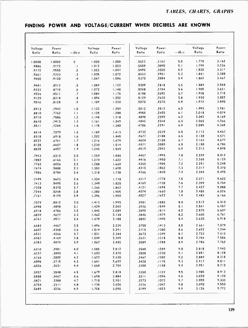
TABLES, CHARTS, GRAPHS
FINDING POWER AND VOLTAGE/CURRENT WHEN DECIBELS ARE KNOWN
Voltage Ratio
Power Ratio -db+
Voltage Ratio
Power Ratio
Voltage Ratio
Power Ratio -db+
Voltage Ratio
Power Ratio
1.0000 1.0000 0 1.000 1.000 .5623 .3162 5.0 1.778 3.162
.9886 .9772 .1 1.012 1.023 .5559 .3090 5.1 1.799 3.236
.9772 .9550 .2 1.023 1.047 .5495 .3020 5.2 1.820 3.3 1 1
.9661 .9333 .3 1.035 1.072 .5433 .2951 5.3 1.841 3.388
.9550 .9120 .4 1.047 1.096 .5370 .2884 5.4 1.862 3.467
.9441 .8913 .5 1.059 1.122 .5309 .28 1 8 5.5 1.884 3.548
.9333 .8710 .6 1.072 1.148 .5248 .2754 5.6 1.905 3.631
.9226 .85 1 1 .7 1.084 1. 1 75 .5 1 88 .2692 5.7 1.928 3.715
.9120 .83 1 8 .8 1.096 1.202 .5129 .2630 5.8 1.950 3.802
.9016 .8 1 28 .9 1.109 1.230 .5070 .2570 5.9 1.972 3.890
.8913 .7943 1.0 1.122 1.259 .5012 .2512 6.0 1.995 3.981
.8810 .7762 1.1 1.135 1.288 .4955 .2455 6.1 2.018 4.074
.8710 .7586 1.2 1.148 1.318 .4898 .2399 6.2 2.042 4.169
.8610 .7413 1.3 1.161 1.349 .4842 .2344 6.3 2.065 4.266
.8511 .7244 1.4 1. 1 75 1.380 .4786 .2291 6.4 2.089 4.365
.8414 .7079 1.5 1.189 1.413 .4732 .2239 6.5 2.113 4.467
.8318 .6918 1.6 1.202 1.445 .4677 .2188 6.6 2.138 4.571
.8222 .6761 1.7 1.216 1.479 .4624 .2138 6.7 2.163 4.677
.8128 .6607 1.8 1.230 1.514 .4571 .2089 6.8 2.188 4.786
.8035 .6457 1.9 1.245 1.549 .4519 .2042 6.9 2.213 4.898
.7943 .6310 2.0 1.259 1.585 .4467 .1995 7.0 2.239 5.012
.7852 .6166 2.1 1.274 1.622 .4416 .1950 7.1 2.265 5.129
.7762 .6026 2.2 1.288 1.660 .4365 .1905 7.2 2.291 5.248
.7674 .5888 2.3 1.303 1.698 .4315 .1862 7.3 2.317 5.370
.7586 .5754 2.4 1.318 1.738 .4266 .1820 7.4 2.344 5.495
.7499 .5623 2.5 1.334 1.778 .4217 .1778 7.5 2.371 5.623
.7413 .5495 2.6 1.349 1.820 .4169 .1738 7.6 2.399 5.754
.7328 .5370 2.7 1.365 1.862 .4121 .1698 7.7 2.427 5.888
.7244 .5248 2.8 1.380 1.905 .4074 .1660 7.8 2.455 6.026
.7161 .5129 2.9 1.396 1.950 .4027 .1622 7.9 2.483 6.166
.7079 .5012 3.0 1.413 1.995 .3981 .1585 8.0 2.512 6.310
.6998 .4898 3.1 1.429 2.042 .3936 .1549 8.1 2.541 6.457
.6918 .4786 3.2 1.445 2.089 .3890 .1514 8.2 2.570 6.607
.6839 .4677 3.3 1.462 2.138 .3846 .1479 8.3 2.600 6.761
.6761 .4571 3.4 1.479 2.188 .3802 .1445 8.4 2.630 6.918
.6683 .4467 3.5 1.496 2.239 .3758 .1413 8.5 2.661 7.079
.6607 .4365 3.6 1.514 2.291 .3715 .1380 8.6 2.692 7.244
.6531 .4266 3.7 1.531 2.344 .3673 .1349 8.7 2.723 7.413
.6457 .4169 3.8 1.549 2.399 .3631 .1318 8.8 2.754 7.586
.6383 .4074 3.9 1.567 2.455 .3589 .1288 8.9 2.786 7.762
.6310 .3981 4.0 1.585 2.512 .3548 .1259 9.0 2.818 7.943
.6237 .3890 4.1 1.603 2.570 .3508 .1230 9.1 2.851 8.128
.6166 .3802 4.2 1.622 2.630 .3467 .1202 9.2 2.884 8.318
.6095 .3715 4.3 1.641 2.692 .3428 .1175 9.3 2.917 8.511
.6026 .3631 4.4 1.660 2.754 .3388 .1148 9.4 2.951 8.710
.5957 .3548 4.5 1.679 2.818 .3350 .1122 9.5 2.985 8.913
.5888 .3467 4.6 1.698 2.884 .3311 .1096 9.6 3.020 9.120
.5821 .3388 4.7 1.718 2.951 .3273 .1072 9.7 3.055 9.333
.5754 .3311 4.8 1.738 3.020 .3236 .1047 9.8 3.090 9.550
.5689 .3236 4.9 1.758 3.090 .3199 .1023 9.9 3.126 9.772
129
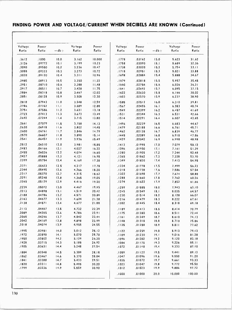
FINDING POWER AND VOLTAGE/CURRENT WHEN DECIBELS ARE KNOWN (Continued)
Voltage Ratio
Power Ratio -db+
Voltage Ratio
Power Ratio
Voltage Ratio
Power Ratio -db+
Voltage Ratio
Power Ratio
.3612 .1000 10.0 3.162 10.000 .1778 .03162 15.0 5.623 31.62
.3126 .09772 10.1 3.199 10.23 . 1 758 .03090 15.1 5.689 32.36
.3090 .09550 10.2 3.236 10.47 .1738 .03020 15.2 5.754 33.11
.3055 .09333 10.3 3.273 10.72 .1718 .02951 15.3 5.821 33.88
.3020 .09120 10.4 3.311 10.96 .1698 .02884 15.4 5.888 34.67
.2985 .08913 10.5 3.350 11.22 .1679 .02818 15.5 5.957 35.48
.2951 .08710 10.6 3.388 11.48 .1660 .02754 15.6 6.026 36.31
.2917 .08511 10.7 3.428 11.75 .1641 .02692 15.7 6.095 37.15
.2884 .08318 10.8 3.467 12.02 .1622 .02630 15.8 6.166 38.02
.2851 .08128 10.9 3.508 12.30 .1603 .02570 15.9 6.237 38.90
.2818 .07943 11.0 3.548 12.59 .1585 .02512 16.0 6.310 39.81
.2786 .07762 11.1 3.589 12.88 .1567 .02455 16.1 6.383 40.74
.2754 .07586 11.2 3.631 13.18 .1549 .02399 16.2 6.457 41.69
.2723 .07413 11.3 3.673 13.49 .1531 .02344 16.3 6.531 42.66
.2692 .07244 11.4 3.715 13.80 .1514 .02291 16.4 6.607 43.65
.2661 .07079 11.5 3.758 14.13 .1496 .02239 16.5 6.683 44.67
.2630 .06918 1 1 .6 3.802 14.45 .1479 .02188 16.6 6.761 45.71
.2600 .06761 11.7 3.846 14.79 .1462 .02138 16.7 6.839 46.77
.2570 .06607 11.8 3.890 15.14 .1445 .02089 16.8 6.918 47.86
.2541 .06457 11.9 3.936 15.49 .1429 .02042 16.9 6.998 48.98
.2512 .06310 12.0 3.981 15.85 .1413 .01995 17.0 7.079 50.12
.2483 .06166 12.1 4.027 16.22 .1396 .01950 17.1 7.161 51.29
.2455 .06026 12.2 4.074 16.60 .1380 .01905 17.2 7.244 52.48
.2427 .05888 12.3 4.121 16.98 .1365 .01862 17.3 7.328 53.70
.2399 .05754 12.4 4.169 17.38 .1349 .01820 17.4 7.413 54.95
.2371 .05623 12.5 4.217 17.78 .1334 .01778 17.5 7.499 56.23
.2344 .05495 12.6 4.266 18.20 .1318 .01738 17.6 7.586 57.54
.2317 .05370 12.7 4.315 18.62 .1303 .01698 17.7 7.674 58.88
.2291 .05248 12.8 4.365 19.05 .1288 .01660 17.8 7.762 60.26
.2265 .05129 12.9 4.416 19.50 .1274 .01622 17.9 7.852 61.66
.2239 .05012 13.0 4.467 19.95 .1259 .01585 18.0 7.943 63.10
.22 1 3 .04898 13.1 4.519 20.42 .1245 .01549 18.1 8.035 64.57
.2188 .04786 13.2 4.571 20.89 .1230 .01514 18.2 8.128 66.07
.2163 .04677 13.3 4.624 21.38 .1216 .01479 18.3 8.222 67.61
.2138 .04571 13.4 4.677 21.88 .1202 .01445 18.4 8.318 69.18
.2113 .04467 13.5 4.732 22.39 .1189 .01413 18.5 8.414 70.79
.2089 .04365 13.6 4.786 22.91 .1175 .01380 18.6 8.511 72.44 .2065 .04266 13.7 4.842 23.44 .1161 .01349 18.7 8.610 74.13 .2042 .04169 13.8 4.898 23.99 .1148 .01318 18.8 8.710 75.86 .2018 .04074 13.9 4.955 24.55 .1135 .01288 18.9 8.811 77.62
.1995 .03981 14.0 5.012 25.12 .1122 .01259 19.0 8.913 79.43 .1972 .03890 14.1 5.070 25.70 .1109 .01230 19.1 9.016 81.28 .1950 .03802 14.2 5.129 26.30 .1096 .01202 19.2 9.120 83.18 .1928 .03715 14.3 5.188 26.92 .1084 .01175 19.3 9.226 85.11 .1905 .03631 14.4 5.248 27.54 .1072 .01148 19.4 9.333 87.10
.1884 .03548 14.5 5.309 28.18 .1059 .01122 19.5 9.441 89.13
.1862 .03467 14.6 5.370 28.84 .1047 .01096 19.6 9.550 91.20
.1841 .03388 14.7 5.433 29.51 .1035 .01072 19.7 9.661 93.33 .1820 .03311 14.8 5.495 30.20 .1023 .01047 19.8 9.772 95.50 .1799 .03236 14.9 5.559 30.90 .1012 .01023 19.9 9.886 97.72
.1000 .01000 20.0 10.000 100.00

TABLES, CHARTS, GRAPHS
FINDING DECIBELS WHEN VOLTAGE/CURRENT RATIO IS KNOWN
Voltage Ratio .00 .01 .02 .03 .04 .05 .06 .07 .08 .09
1.0 .000 .086 .172 .257 .341 .424 .506 .588 .668 .749
1.1 .828 .906 .984 1.062 1.138 1.214 1.289 1.364 1.438 1.51 I
1.2 1.584 1.656 1.727 1.798 1.868 1.938 2.007 2.076 2.144 2.212
1.3 2.279 2.345 2.411 2.477 2.542 2.607 2.671 2.734 2.798 2.860
1.4 2.923 2.984 3.046 3.107 3.167 3.227 3.287 3.346 3.405 3.464
1.5 3.522 3.580 3.637 3.694 3.750 3.807 3.862 3.918 3.973 4.028
1.6 4.082 4.137 4.190 4.244 4.297 4.350 4.402 4.454 4.506 4.558 1.7 4.609 4.660 4.711 4.761 4.811 4.861 4.910 4.959 5.008 5.057 1.8 5.105 5.154 5.201 5.249 5.296 5.343 5.390 5.437 5.483 5.529 1.9 5.575 5.621 5.666 5.711 5.756 5.801 5.845 5.889 5.933 5.977
2.0 6.021 6.064 6.107 6.150 6.193 6.235 6.277 6.319 6.361 6.403 2.1 6.444 6.486 6.527 6.568 6.608 6.649 6.689 6.729 6.769 6.809 2.2 6.848 6.888 6.927 6.966 7.008 7.044 7.082 7.121 7.159 7.197 2.3 7.235 7.272 7.310 7.347 7.384 7.42 I 7.458 7.495 7.532 7.568 2.4 7.604 7.640 7.676 7.712 7.748 7.783 7.819 7.854 7.889 7.924
2.5 7.959 7.993 8.028 8.062 8.097 8.131 8.165 8.199 8.232 8.266 2.6 8.299 8.333 8.366 8.399 8.432 8.465 8.498 8.530 8.563 8.595 2.7 8.627 8.659 8.691 8.723 8.755 8.787 8.818 8.850 8.881 8.912 2.8 8.94 3 8.974 9.005 9.036 9.066 9.097 9.127 9.158 9.188 9.218 2.9 9.248 9.278 9.308 9.337 9.367 9.396 9.426 9.455 9.484 9.513
3.0 9.542 9.571 9.600 9.629 9.657 9.686 9.714 9.743 9.771 9.799 3.1 9.827 9.855 9.883 9.9 1 1 9.939 9.966 9.994 10.021 10.049 10.076
3.2 10.103 10.130 10.157 10.184 10.211 10.238 10.264 10.291 10.317 10.344 3.3 10.370 10.397 10.423 10.449 10.475 10.501 10.527 10.553 10.578 10.604
3.4 10.630 10.655 10.681 10.706 1 0.73 1 10.756 10.782 10.807 10.832 10.857
3.5 10.881 10.906 10.931 10.955 10.980 1 I .005 11.029 11.053 11.078 1 1. 102
3.6 11.126 11.150 1 1.1 74 1 1. 198 11.222 11.246 11.270 11.293 1 1.3 1 7 11.341
3.7 11.364 11.387 1 1.41 1 11.434 11.457 1 1.48 1 11.504 11.527 11.550 11.573 3.8 11.596 11.618 11.641 11.664 11.687 11.709 1 1 .732 11.754 11.777 11.799 3.9 1 1.82 1 11.844 11.866 11.888 1 1.9 10 1 1.93 2 11.954 11.976 11.998 12.019
4.0 12.041 12.063 12.085 12.106 12.128 12.149 12.171 12.192 12.213 1 2.2 34 4.1 12.256 12.277 12.298 12.319 12.340 12.361 12.382 12.403 12.424 12.444 4.2 12.465 12,486 12.506 12.527 12.547 12.568 12.588 12.609 12.629 12.649 4.3 12.669 12.690 12.710 12.730 12.750 12.770 12.790 12.810 12.829 12.849
4.4 12.869 12.889 12.908 12.928 12.948 12.967 12.987 13.006 13.026 13.045
4.5 13.064 13.084 13.103 13.122 13.141 13.160 13.179 13.198 13.217 13.236 4.6 13.255 1 3.2 74 13.293 13.312 13.330 13.349 13.368 13.386 13.405 13.423 4.7 13.442 13.460 13.479 13.497 13.516 13.534 13.552 13.570 13.589 13.607 4.8 13.625 13.643 13.661 13.679 13.697 13.715 13.733 13.751 13.768 13.786 4.9 13.804 13.822 13.839 13.857 13.875 13.892 13.910 13.927 13.945 13.962
5.0 13.979 13.997 14.014 14.031 14.049 14.066 14.083 14.100 14.117 14.134 5.1 14.151 14.168 14.185 14.202 14.219 14.236 14.253 1 4.2 70 14.287 14.303 5.2 14.320 14.337 14.353 14.370 14.387 14.403 14.420 14.436 14.453 14.469 5.3 14.486 14.502 14.518 14.535 14.551 14.567 14.583 14.599 14.616 14.632 5.4 14.648 14.664 14.680 14.696 14.712 14.728 14.744 14.760 14.776 14.791
5.5 14.807 14.823 14.839 14.855 14.870 14.886 14.902 14.917 14.933 14.948 5.6 14.964 14.979 14.995 15.010 15.026 1 5.04 1 15.056 15.072 15.087 15.102 5.7 15.117 15.133 15.148 15.163 15.178 15.193 15.208 15.224 15.239 1 5.2 54 5.8 15.269 15.284 15.298 15.313 15.328 15.343 15.358 15.373 15.388 15.402 5.9 15.417 15.432 15.446 1 5.46 1 15.476 15.490 15.505 15.519 15.534 15.549
6.0 15.563 15.577 15.592 15.606 1 5.62 1 15.635 15.649 15.664 15.678 15.692 6.1 15.707 1 5.72 1 15.735 15.749 15.763 15.778 15.792 15.806 15.820 15.834 6.2 15.848 15.862 15.876 15.890 15.904 15.918 1 5.9 3 1 15.945 15.959 15.973 6.3 15.987 16.001 16.014 16.028 16.042 16.055 16.069 16.083 16.096 16.110 6.4 16.124 16.137 16.151 16.164 16.178 16.191 16.205 16.218 16.232 16.245
131
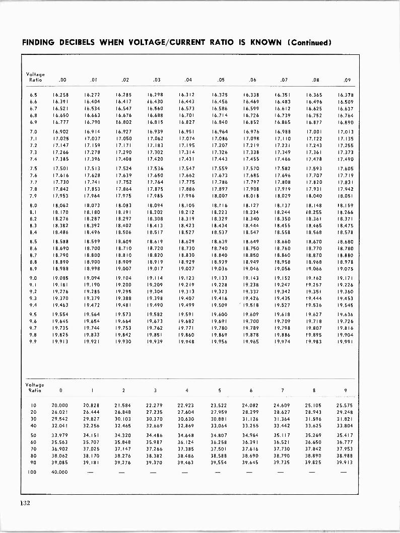
FINDING DECIBELS WHEN VOLTAGE/CURRENT RATIO IS KNOWN (Continued)
Voltage Ratio .00 .01 .02 .03 .04 .05 .06 .07 .08 .09
6.5 16.258 16.272 16.285 16.298 16.312 16.325 16.338 16.351 16.365 16.378
6.6 16.391 16.404 16.417 16.430 16.443 16.456 16.469 16.483 16.496 16.509 6.7 16.521 16.534 16.547 16.560 16.573 16.586 16.599 16.612 16.625 16.637 6.8 16.650 16.663 16.676 16.688 16.701 16.714 16.726 16.739 16.752 16.764 6.9 16.777 16.790 16.802 16.815 16.827 16.840 16.852 16.865 16.877 16.890
7.0 16.902 16.914 16.927 16.939 16.951 16.964 16.976 16.988 17.001 17.013 7.1 17.025 17.037 17.050 17.062 17.074 17.086 17.098 1 7.1 10 17.122 17.135 7.2 17.147 17.159 1 7.1 7 1 17.183 17.195 17.207 1 7.2 19 17.231 17.243 17.255 7.3 17.266 17.278 17.290 17.302 17.314 17.326 17.338 17.349 17.361 17.373 7.4 17.385 17.396 17.408 17.420 17.431 17.443 17.455 17.466 17.478 17.490
7.5 17.501 1 7.51 3 17.524 17.536 17.547 17.559 17.570 17.582 17.593 17.605 7.6 17.616 17.628 17.639 17.650 17.662 17.673 17.685 17.696 17.707 17.719 7.7 17.730 17.741 17.752 17.764 17.775 17.786 17.797 17.808 17.820 1 7.83 1
7.8 17.842 17.853 17.864 17.875 17.886 17.897 17.908 17.919 1 7.93 1 17.942
7.9 17.953 17.964 17.975 17.985 17.996 18.007 18.018 18.029 18.040 18.051
8.0 18.062 18.073 18.083 18.094 18.105 18.116 18.127 18.137 18.148 18.159
8.1 18.170 18.180 1 8.19 1 18.202 1 8.2 12 18.223 18.234 18.244 18.255 18.266 8.2 18.276 18.287 18.297 18.308 18.319 1 8.329 18.340 18.350 1 8.36 1 1 8.37 1
8.3 18.382 18.392 18.402 1 8.41 3 18.423 18.434 18.444 18.455 18.465 18.475 8.4 18.486 18.496 18.506 18.517 1 8.527 18.537 18.547 18.558 18.568 18.578
8.5 18.588 18.599 18.609 18.619 18.629 18.639 18.649 18.660 18.670 18.680 8.6 18.690 18.700 18.710 18.720 18.730 18.740 18.750 18.760 18.770 18.780
8.7 18.790 18.800 18.810 18.820 18.830 18.840 18.850 18.860 18.870 18.880 8.8 18.890 18.900 18.909 18.919 18.929 18.939 18.949 18.958 18.968 18.978 8.9 18.988 18.998 19.007 19.017 19.027 19.036 19.046 19.056 19.066 19.075
9.0 19.085 19.094 19.104 19.114 19.123 19.133 19.143 19.152 19.162 19.171
9.1 19.1 8 1 19.190 19.200 19.209 19.219 19.228 19.238 19.247 19.257 19.226 9.2 19.276 19.285 19.295 19.304 19.3 1 3 19.323 19.332 19.342 19.351 19.360 9.3 19.370 19.379 19.388 19.398 19.407 19.416 19.426 19.435 19.444 19.453 9.4 19.463 19.472 19.481 19.490 19.499 19.509 19.518 19.527 19.536 19.545
9.5 19.554 19.564 19.573 19.582 19.591 19.600 19.609 19.618 19.627 19.636 9.6 19.645 19.654 19.664 19.673 19.682 19.691 19.700 19.709 19.718 19.726 9.7 19.735 19.744 19.753 19.762 19.771 19.780 19.789 19.798 19.807 19.816 9.8 19.825 19.833 19.842 19.851 19.860 19.869 19.878 19.886 19.895 19.904 9.9 19.913 19.921 19.930 19.939 19.948 19.956 19.965 19.974 19.983 19.991
Voltage Ratio 0 I 2 3 4 5 6 7 8 9
10 20.000 20.828 21.584 22.279 22.923 23.522 24.082 24.609 25.105 25.575 20 26.021 26.444 26.848 27.235 27.604 27.959 28.299 28.627 28.943 29.248 30 29.542 29.827 30.103 30.370 30.630 30.881 31.126 31.364 31.596 31.821 40 32.041 32.256 32.465 32.669 32.869 33.064 33.255 33.442 33.625 33.804
50 33.979 34.151 34.320 34.486 34.648 34.807 34.964 35.117 35.269 35.417 60 35.563 35.707 35.848 35.987 36.124 36.258 36.391 36.521 36.650 36.777 70 36.902 37.025 37.147 37.266 37.385 37.501 37.616 37.730 37.842 37.953 80 38.062 38.170 38.276 38.382 38.486 38.588 38.690 38.790 38.890 38.988 90 39.085 39.181 39.276 39.370 39.463 39.554 39.645 39.735 39.825 39.913
100 40.000
132

TABLES, CHARTS, GRAPHS
Distance in Miles From an FM Transmitter to Its 54 dbu (0.5 my/m) Contour For Various Heights and Powers
Ln Ln Ln Ln Ln O M O W O e N O O Ln M O e Ln M O e Ln en M O n Ln N e Ln N - O O O O O O e co e e e N. f\
Ln
f\ N. N. .O O
In
.O
Ln
O
Ln
.O W Ln
In
Ln
v
V
Ln W O N. Ln (+1 O W Ln N O O I\ Ln M O n Ln M O W .0 Ln N O Ln N Ln
O O O
W
O. O.
Ln
e e e e N. n
{n
N. n
Ln
N. n .O .O
Ln
.0
Ln
O In Ln Ln Ln cl-
an
v v I+1
o Ln M 2 O W M O CO .0 Ln O N. Ln M W N. LA M O n M O Ln O O O O e co
Ln
co
n
W
Ln
n
n
N. N. N. N. .O .O .O .O .O Ln an Ln Ln Ln v e- e-
LO
re
Ln
/9
O .O LV O O. n Ln f.9 O e .O v N O Ln M 0 Ln - Ln O O e W e N. N. N.
Ln
N. N. O O O
an
.O .O .O Ln
Ln
Ln Ln Ln
Ln
v v V
Ln
v
LA
M re N
Ln N N. LO N O N. LO N O. CO .O Ln Ce O e .O v N O N. Ln N e Ln N CO
CO e e
Ln
e n N.
Ln
N. .O .O .O
Ln
.O
s
.O .0 O Ln LO
Ln
Ln
Ln
Ln Ln v v v M
Ln
M M
Ln
N
Ln
N
N O N O n Ln re O CO Ln c N O O W .O Ln N O W .O r1 e Ln N W v e W
W
CO
Ln
N.
M
N. N.
O.
N.
n
.O
Ln
.O
Ln
O
O
.O
Ln
CO.
O
N.
O
Ln
'n
Ln
e v
Ln
Ln
N
Ln
Ln
O
LO
Ir, e
Ln
N.
v
Ln
V
Ln
N
v
O
v
e
l.9
Ln
M
Ln
N
M
Ln
O
N
Ln
O
N
N
-
O CO n n n n .O .O O O .O Ln Ln Ln Ln Lll Ln V v tt 7 v !+1 M M N N N -
U) Ln
M O n LO N O N. Ln LO M N O W N. LO M W n Ln N O. n M O. t}' N
Ln
N. O .O O .O
Ln
.O
LA
Ln Ln Ln Ln LO In
Ln
v v v
n
v c M
U)
M
LO
M (.'1
n
N N
W
N - Ln
- U)
O n Ln M O W Ln M N O CO .O Ln M O CO Ln M N W n ^ fV .O .O O .O .O Ln U) Ln Ln Ln Ln v v v v v v M M M Ln N N N N - -
Ln Ln Ln Ln Ln Ln Ln Ln Ln Ln Ln LO Ln Ln LO N. N W M O
.
W .O . v N O
. W f\ .
ln V M .
O CO .
.O . a .
N .
O .
W .
.O N co. .
an .
O
O
O .O
Ln
.O
Ln
Ln
Ln
ln Ln
LA
LA LA
Ln
e 'II' V' e-
Ln
e
Ln
e e- M M M
N
M
.O
M N N N N - - n
-
O .O
e Ln
O Ln Ln
N Ln
O Ln
e v LO v Ln {T
M v N v O ct-
OP M
e f.'1
.O M
Ln M
M !W M
O N
e N
.O N N N
O. - t` M - O
N Ln Ln LO LO LO Ln Ln LO U) Ln N Ln M N O e .O v N O O W .O Ln v N - O e N. Ln M O. n Ln N e U)
Ln
Ln Ln Ln
Ln
cl-
Ln
v V v v
Ln
v !.9 M M M
an
ni en f+f
Ln
N
Ln
N
Ln
N N N - Ln
- - Ln
- v
O e Ln v N O e n O Ln r1 N O O CO .O Ln v N - O n .O M - n Ln
Ln
Lo v v v v
LO
v
Ln
M !.'1
Ln
M
LO
M
Ln
M (.'1
Ln
M M N
Ln
N
Ln
N N
tn
N N
Ln Ln .O
f\ Ln M N O W .O Ln M N O W e n Ln [{ M O e f\ .O v N O .O v
N
v
LA
O
e-
O
v
W
v
.O
(+1
Ln
I.'1
Ln
N
re
-
M
O
f.'L
O
re
W
M
f\
N
ln
.O
N
Ln
N
LA
en
N
M
N
Ln
LV
Ln
O
N
Ln
O
N
e n tn Ln V'
Ln
N LO
O N e
W Ln v v e- M M M en M en N N N N N N N N N
O LO Ln .
Ln .
Ln Ln Ln Ln .
Ln Ln .
Ln .. U) n .
M .
N .
CO M
N M
Ln M
M M
N M
- M
O N
e N
N. N
O N
U) N
e N
M N
N N
- N
O N
P e e .O In e N - W N. W
N Ln Ln Ln Ln Ln Ln Ln Ln Ln Ln Ln .O
v N. O O e .O Ln v 119 N - O O. e n N. .O Ln M N - e e O v
sr
!.1 M M M N
Ln
N
LO
N N N
Ln
N
Ln
N N N
Ln
N
Ln Ln M N n O O. e n Ln v fM N - O O O e e N. O LO LO V' M N - O. e n Ln v M N N N N N N N N N N
LO Ln LO LO LO Ln Ln Ln LO Ln LO N M Ln N n .O Ln v en N - O O e co n r .O O Ln v !+f I.'L N - O O W n .O Ln M N N N N N N N
W an Ln N O' Ln .O tf Ln Ln N t\ re .O n O N Ce N O O O. e n N. .O Ln Ln ,,t .4- M M N - O o e e n .O Ln e M
O N
N N N
Ln
N N
LO Ln Ln Ln n N n N Ln W W O O- e CO n N. .O Ln Ln v M M N N - - O O W W r N. .O Ln Ln v N
L¿ O O
O O
O O
O O
O O
O O
O O
O O
O O
O O
O O
O O
O O
O O
O O
O O
O O
O O
O O
O O
O O
O O
O O
O O
O O
O O
O O
= C V' Ce
N en
O rn
W N
.O N
e- N
N. N
O N
O e N. .O Ln d' fM N - O O CO N. .O Ln v M N -
133
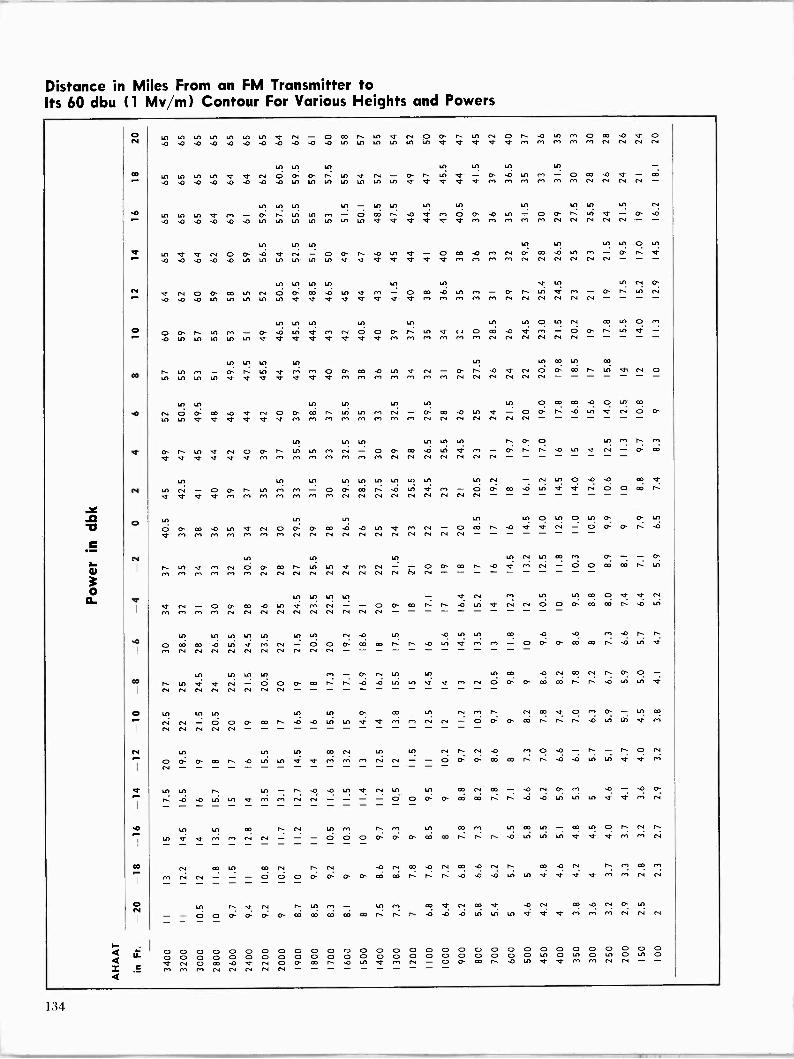
Distance in Miles From an FM Transmitter to Its 60 dbu (1 My/m) Contour For Various Heights and Powers
o N
R
N
O
03
N
O
N
O
N
O N
10 lA LA Ln Ln LA LA et rV O CD N- LA v N O O n tA N O f` .O LO Al O o0 .0 v O .0 .0 ,0 .0 .0 .0 .O .0 .0 .0 .0 LA LA LA LA LA u) er et er et ot rn rn rn Al en N N Al N
Ln
LA 10 LA LA et er N O OP O f` LA et N O f\ Ln O` .O LA r+) - O e .O eY - CO
.0 .0 .0 .0 .0 .0 .0 .0 {n 1() LO LA {() {A 1f) e{ er er er rn r+) en r+) r+) Ni N Ni N - LA {A 10 LA lA LA an LA LA LA LA an N
e LA 10 e! rn OP n LA LA Al O O 1 .0 e{ Al O P .0 )O - O O n l!1 v - O .O .0 .0 .0 .0 .0 .0 LA 10 1¡) LA LA an an et er d- ei v er M M rm r+) r+) N N N N N - -
1n 10 lA 1A l0 LA 10 O LA
LA er et N O O .0 v N O OP N .0 an V' O CO .0 r.') N O co .0 Ln fr) - O n er .0 .0 .0 .0 .0 LA LA lA LA an 1A v v v er V v er M M rn M Ni N N Ni Ni N - - -
LA LA u) 1A LA 111 V' 1A 121 N P .4- Ni O O 00 1A Ni d O co .O LA er Al O CO .0 LA rn O- n LA V M - O r` an N .0 .0 .A 1A LA LA an LA v it v v v er v er !+1 M - - - -
1A LA lA U) 1A u) LA O LA N CO LA O rn
O O r\ LA M O .O LA V' rn Ni O O O` f\ LA et r.I O e .O er r1 - O P r` LA er - .0 LA in 1A an LA v v v v ef eY v e{ Al M Al M AL Al N N N N N N
1A LA LC) LA LA LA CO an CO
n LA M O. N. LA er rn r+1 O 0 m .O in er Ni - OP N .0 et N O O CO. n an V N O LA LA LA LA er v e{ er v er 'V en N N N
1A LA 1A 1A 11) u) ln O CO CO .O O LA co
N O O co .0 eY N O O CD f` LA LA M N - O CC .0 LA v - O OP r` .0 Ln et N O O 1A LA et er eF it v et M re en re re rn M M N Ni Ni N Ni Ni Ni
LA LA LA LA an LA n P O LA r+) f` M O C` LA eY N O O` f\ LO LA r+) N - O Cr. e .0 LA et r+f - O f` f\ .0 LA et N - O DD
eY eY et 'R v er en rn M !+) rn rn rn en Ni Ni Ni Ni Ni Ni N
LA lA LA an an LA LA LA LA 1A N - N LA O .O .0 CD ei LO N - O Co n 1A r+) r.) O O. OD n .0 LA er M - O O CO .0 an e et N 0 0 e h v V et er ni rn ei en r) rn r+) Ni Ni Ni Ni Ni N N N fV
Ln 1A LA 1A LA O LA O an O O an
O P e .0 LA et N O O O CO .0 .0 an v en N - O CD n .0 et er N - O OP O f` O !+f rn M rn en r+) M Ni Ni Ni Ni Ni Ni Ni N Ni Ni Ni
ln Ln Ln LA N lA CO rrl O` - O r LA v r+) N O Cr- e N- rn N - O O CO A. .O V re) N - O O CD e M r+) r+) r+1 rn r+f N N N N N N N N N - N tV
1A to LA to - eY N rn )A an CO O et er Ni
er N - O O` 00 .O an er M Ni - - O O ao h an er N N O. 0 0 m W M r+) P1 rn N Ni Ni N Ni Ni N Ni Ni Ni
lA LA LA LA an an LA N .O lA .O 1A LA Co .O .O M .O re,
O co co .O LA et rn co - O O O CO. CO r` n .O LA of rh M - O O O m co t\ .O LA
M co co N N N co N N N N
lA Ln Ln LA M P N LA Ln LA 00 .0 N CO Al f` 0` O - C\ LA eY er- Ni - 0 0 0 OD r` t` .0 .0 LA Ln et er rn N O O OP eo CO. t` n .0 LA LA et N N N N N N N N
Ln 1A LA lA LA O CD tn N /') n N CD v O /") O - Ln CO
N N - O O O CO n .O .0 lA in er ef r+) rn N N - O O o- 00 r-: n n .O 1A LA .4 rn
Ni Ni Ni Ni Ni
LA Ln ln CO N lA
O O O` e n .O 1A 1A e{ e{ M rn r+) N N N
LA N t` N .0 M O .O r\ - n O N - - O O` O 00 co n f\ .O .O 1A an
LA Ln C\ .D .O an et' N 1A an CO Ni CO .O N O Al .O - .O O n .0 .0 LA 1A er Al. en N N - - - - 0 0 0 O e e .0 .O LA LA LA ef et r+) N
Ln Ln CO N- N LA en CO M 111 CO 1A co LA O N. N n 1A e{ er M M N N - - - 0 0 0 O P O. DD CO .0 Ln LA 1n v et ct re. nt N
N CO LA D7 N r\ N .0 N CO .O N CO .O N f` co .O N r\ r+) CO Al
M N N - - - O O O O: O P O CO e r` f` f\ .O 0 .O an LA et ef ef er rn rh N N
LA r\ ef N n lA - in r+) CO V N CO er .O N CO .O N O` LA
- - O O O O OP O CO m oD e w .O .O LA an LA V cc; m rn co. N co
O O O O O O O O O O O r) O O O O O O O O O O O O O O O O O O O O O O O O O O O O O O O O O O O O O O O O O O 1A O LA O Ln O LA O v N O m .0 v N O O` e N. .0 LA er rn N - O O CO f\ .0 1.0 er et M r+) N N - - M rn el N N N N N
134

T Ì RLES, CH: iRTS, GR:1 PHS
Distance in Miles From an FM Transmitter to Its 80 dbu (10 my/m) Contour For Various Heights and Powers
o N
N
O
CO
CO
N
O
N
o
N
O N
Ul Ln Ln Ln lt) LO Ln W LO t[) O CO
-O ln ni O CO - a o- co N O W 1 ln v N O O e a a a cr rit r) r) r) r) r) M N N N N N N N (N
U1 Lo Ln u) Ln to tn Ln N O N O O CO In ln N - O OP co n e Ina ni tV O OP W n Ln V fV O W -O e v V r) r) r) rn r) r) N N N ni N N N CN CN
1n Ln Ln ln u) LO IO LO Ln Ln Ln O` Ln N . . . . . . . . . . . . .
W NO kt) V' CN O P W h -O 111V rl N O P m W O ln V' N - W n ln r) M M r) M M CN CN N N CN CN CN N CN CN
LO Ln LOU) u) Lo 111 L[) u) ln CO n n V N - a Cr- h O Lo a rn N O O o- co N. 1 .O to rh N - O: 1 -O [r NI r) r) r) CN N N N N N CN CN CN CN
Lo 1n LO lt) Lo ln Lo tO ln N N N O N . . . . . . . . . . . . .
O Cr- CO -O 1n rf - - 0 0 0 W W r .O lA Lo a m N O O W ) -O M CN CN CN CN CN N CN N N N
)O 1.0 Lo N Ln ln LO 11) O N Ln N N n . . . . . . . . . . . . .
O Ln a rl Ni - O P O W co 1- n O Lo e m CN - O ? W t -O lA rn CN N CN N CN CN N
LO ,O Lo LO 1n Ln LO LO LO r) CO LO n co n rn rn N - O P o- W 1. N- ,O tri Ln v R ri N - - O OP W co n -O Ln V rn N CN N N
ln ln Ln W 1n
O O W CO n n -0 LO V V N
lO lO N N CO r) CO N t\ O O N m m CN - - O P W W n Ln V r)
LO Ln Ln LO W tA N n N W .c1 O LO N LO W . . . . . . . . . . . . . . . . .
W t` 1 O in W M m N N - - O O O W W t f\ 1 -O O In tY M N
LO l0 lO W N O h M co N O n r) CO N n M r) . . . . . . . . . . . . . . . . .
LO W V f m N N - - O O O O W W co f` 1 n O O Ln Lo m N
LO Ln co V N O 1n O O N CN - - - O O O P W W W W -O Ln to .1 .2 r) r) N
W 1n `V W n .0rn 0 0 n V N W ,O W W n N ,O O P CO: W CO. W CO. co 1-: f` n LI; Ln W v v M r) N -
r) r) O O co n -O rf OP 1` .O v N CO ,O N CO -O N co r) n 1\ h h 1, n 1 -O e .O -O .O lo LO LO In 1n 1n v 7 <f r) r) r)
O O O O CO n .O v rn niN O O CO V N O o- V N W -O Ln
O O O ln ln ln W IO ln Ln M r) r) r) N N CN
W W W CO 1, n 1, -O .O 121 -ci- rn N N O O co 1 V N O CO -O N CO r) . . . . . . . . . . . . . . . . . . . . . . . . .
V' V' V V V K V' V' V V `Y M M r)
O O O O O P CO CO n N. .O - O co n Ln N OP 1 . . . . . . . . . . . . . . . . . . . . . . . . .
cr a a <} m r) r) m m m m m m m m m rn m rv N N N N--- N N N N N N N O O O O W co n n e .O tn v rn O co Ln O r) r) rf
O e W tn Ln Lo LO tn Ln r) rn CN N N N O O co rl Cr -
CN: N N N N N N N N N N N N N N N N N N N N O
N N N N O O O O O O O O W W W 1 n r\ n ,O tn rm N CO
N N N N N N O
CO co co co co co co co co W co n n n N O -O . . . . . . . . . . . . . . . . . . . . . . . . . . .
N., r) r) rf M N,r) M N N N N N N N N N N N O O` CO Ln . . . . . . . . . . . . . . . . . . . . . . . . 0 0 0
O O O O O O O O O 000000000000000000 O O O O O O O O O O O O O O O O O O O O O O O O a a a V N O co .O V CN O O W n -O LO V' tn CN - O OP W h -0 LO v Ln N - R1 r) r) N N N N N
135
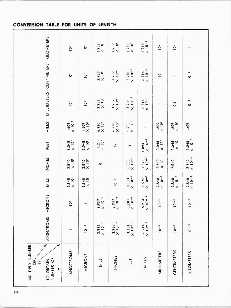
CONVERSION TABLE FOR UNITS OF LENGTH
LO ce w F- N. '6, N. `«b -p - v I
W , ,, r- r, CO -0 -o
0 O O O
m X O rn X
N rn X
N- ,o X
O O - J N cc w W is. r6 r`I -I vl
..z. m- r+M O co 0 -0 0 I
I- O CI.CV:
m X -
m X N- `^ X
N- .o X
- - 0 Z w U V) CC W
r F- ro rI -I eI LL,
2 ^ O O - M- O:
M O O - CO O N- -O N- - - p I o
li J cn X re;
X rn X ,O X - 2
N O m
O p .4on0 O p O O P p Cr. p O O 0 0- ro - M- OD - 0- 0- O -O -X sO -X M
.OX rn
,oX N LiX
.O -X .O -X .O -
F_ aoO aDo O P
I co 7,' co CD
V CO I
w et - V' - N - N O e - - e O LU LL X X X co X MoX
w oO Ó m I I O O 0 0 1 = e rn O t. O e- e e O LO V)O - m - 11)- LO LO LO-
Z N X NX cc; X -X m
r4 N N X
V) O po 0 MI co I O I o I O I J er - et - I M O n O e O e O 'e 0 ir) ir) - o rn - ir) - Lc)-
Lc? - u? - 2
in
r4 N X cd X c4 NX c4
Z 0 v N. 'Ì' MO r\I MO -I ao0 et1
O- Q ceO
U_ - - - r,,X
- ce:O mX
N- mX
N .3X 0 - 0 - 0 -
2 L.) i i -¡ er m
I- 1 ro - r+0 - aoo -0 I I
I
V) 0 OP O0 CV - N - 0 0 0 0 - ^''X `^X MX °X - - - Z Q
ce w CO N 2 2 N W cew Z Z LL
LL CZ O N w w WF- w W
JO m Q °O lil -t N
` U 2
Z W íi J ` J Oa J
0m 2 Q U Y D 0P 2 F -z
136

TABLES, CHARTS, GRAPHS
a( alternating current rf audio frequency AFC automatic frequency
control a-rn amplitude modulation amp ampere Ati.a American Standards
Association AS'l'M American Society for
Testing Materials AVC automatic volume control ave average
susceptance RCI) binary-coded decimal C capacitance C Centigrade, degrees
Centigrade (m centimeter COI) cash on delivery cps cycles per second a continuous wave
/) dissipation factor (Il) decibel dbm decibel referred to one
milliwatt (l( direct current E voltage FIA Electronics Industries
Association emf electromotive force I Fahrenheit, degrees
Fahrenheit f farad / frequency fin frequency modulation f.o.b. free on board G conductance g gravitation constant
gigacycles per second transconductance
h henry h, forward current -transfer
ratio h, short-circuit input
impedance h open -circuit output
admittance h, reverse voltage -transfer
ratio / current IFC International
Electrotechnical Commission
11.:F F. Institute of Electrical and Electronics Engineers
i -f intermediate frequency in. inch 1 P Institute of Radio
Engineers
SYMBOLS AND PREFIXES
ISO
kg kva kw L lab lb LC If ing m m ma max mbar Mc mh mil min mm mmho mi? Mtz MM? my mw
nsec nZj
oz
PF pf PH
PP ppm p -to -p prf
O R
RC r(°
rf RH rms rpm
se( synC
T
International Standards Organization
11--=1 kilo I 10 3)
kilogram kilovolt ampere kilowatt inductance laboratory pound inductance -capacitance low frequency logarithm mass meter; milli (10 )
milliampere maximum millibar megacycles per second millihenry 0.001 inch minimum; minute millimeter millimho milliohm megohm mega megohm millivolt milliwatt nano (10-1)1; any
number nanosecond nanomho ounce parallel, as L power factor picofarad hydrogen in
concentration push-pull; pages parts per million peak -to -peak pulse repetition
frequency quality factor resistance registered trademark resistance -capacitance referred to radio frequency relative humidity root -mean -square revolutions per minute series, as I,, second synchronous,
synchronizing period temperature time
uhf
va hf v1 f
vol rs
w
t"
1
7,
(Y
ultra -high frequency velocity volt voltampere very high frequency very low frequency volume versus watt reactance admittance impedance short-circuit forward
current -transfer ratio (common base)
short-circuit forward current -transfer ratio (common emitter)
reflection coefficient increment loss angle phase angle wavelength micro- (10-6) microampere microbar microfarad microhenry microsecond microvolt ohm mho angular velocity (27/)
PREFIXES
Orders of magnitude from 1012 to 1018 are designated by the fol- lowing prefixes:
Order Prefix Symbol 1012 Cera T
10» giga G I O6 mega M 103 kilo k
102 hecto h
IO deka da 10-1 deci d 10-2 tenti c 10-a milli m I0-" micro 10-» nano n
10_12 pico p 10-15 femto f 10 1` atto a
137

FREQUENCY DESIGNATION OF FM BROADCAST CHANNELS
Freq. (Mc):
Channel No.
Freq. (Mc):
Channel No.
Freq. (Mc):
Channel No.
88.1 201 94.9 235 101.5 268 88.3 202 95.1 236 101.7 269 88.5 203 95.3 237 101.9 270 88.7 204 95.5 238 102.1 271 88.9 205 95.7 239 102.3 272
89.1 206 95.9 240 102.5 273 89.3 207 96.1 _ 241 102.7 274 89.5 208 96.3 242 102.9 275 89.7 209 96.5 243 103.1 276 89.9 210 96.7 244 103.3 277
90.1 2 1 1 96.9 245 103.5 278 90.3 212 97.1 246 103.7 279 90.5 213 97.3 247 103.9 280 90.7 214 97.5 248 104.1 281 90.9 215 97.7 249 104.3 282
91.1 216 97.9 250 104.5 283 91.3 217 98.1 251 104.7 284 91.5 218 98.3 252 104.9 285 91.7 219 98.5 253 105.1 286 91.9 220 98.7 254 105.3 287
92.1 221 98.9 255 105.5 288 92.3 222 99.1 256 105.7 289 92.5 223 99.3 257 105.9 290 92.7 224 99.5 258 106.1 291 92.9 225 99.7 259 106.3 292
93.1 226 99.9 260 106.5 293 93.3 227 100.1 261 106.7 294 93.5 228 100.3 262 106.9 295 93.7 229 100.5 263 107.1 296 93.9 230 100.7 264 107.3 297
94.1 231 100.9 265 107.5 298 94.3 232 1 0 1. 1 266 107.7 299 94.5 233 101.3 267 107.9 300 94.7 234
CHANNELS AVAILABLE FOR ASSIGNMENT TO NONCOMMERCIAL EDUCATIONAL FM STATIONS
Freq Channel Freq. (Mc): No. (Mc):
Channel No.
Freq. (Mc):
Channel No.
88.1 201 89.5 208 90.9 215 88.3 202 89.7 209 91.1 216 88.5 203 89.9 210 91.3 217 88.7 204 90.1 211 91.5 218
88.9 205 90.3 212 91.7 219 89.1' 206 90.5 213 91.9 220 89.3 207 90.7 214
' The frequency 89.1 Mc in the New York City metro- politan area is reserved for the use of the United Nations.
CONVERT ELECTRICAL DEGREES TO FEET, OR VICE VERSA WHEN FREQUENCY AND EITHER FEET OR DEGREES IS KNOWN From the expression
degrees 300 2.734 Feet 360° f(Iv1c) X 3.281 degrees X fl Mc)
The following ratio may be set up on the slide rule using C and D scales:
2.734 feet f(Mc) degrees
Set 2.734 on scale C over frequency in megacycles on scale D; read feet and degrees on scales C and D, respectively. In some instances it may be convenient to use the folded scales CF and DF.
METRIC CONVERSION
To convert pounds to kilograms. multiply by .1536
To convert inches to centimeters. multiply by 2.514
TELEPHONE CABLE COLOR CODE Pair No.
1
2
3
4 5
6 7
8
9 10 II 12 13 14 15 16 17 18 19 20 21 22 23 24 25 26 27 28 29 30 31 32 33 34 35 36 37 38 39 40 41 42 43 44 45 46 47 48 49 50
Color Blue Orange Green Brown Slate Blue White Blue Orange Blue Green Blue Brown Blue Slate Orange White Orange Green Orange Brown Orange Slate Green White Green Brown Green Slate Brown White Brown Slate Slate White Blue Orange Green Brown Slate Blue White Blue Orange Blue Green Blue Brown Blue Slate Orange White Orange Green Orange Brown Orange Slate Green White Green Brown Green Slate Brown White Brown Slate Slate White Blue Orange Green Brown Slate Blue White Blue Orange Blue Green Blue Brown Blue Slate
NOTE -The last pair in all cables mate, viz.
6 -pair cable 6th pair I1 -pair cable I Ith pair 16 -pair cable 16th pair 26 -pair cable 26th pair 5I -pair cable 51st pair
is a Red
Red Red Red Red Red
Mate White White White White White White White White White White White White White White White White White White White White Red Red Red Red Red Red Red Red Red Red Red Red Red Red Red Red Red Red Red Red Black Black Black Black Black Black Black Black Black Black with White
White White White White White
138
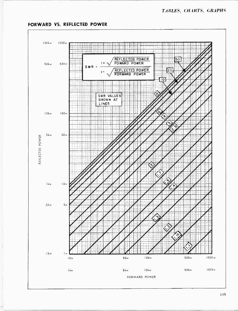
TABLES, CHARTS, GRAPHS
FORWARD VS. REFLECTED POWER
100kw 1000w
50kw 500w
10kw 100w
5kw 50w
Ikw 10w
5kw 5w
.Ikw I
iiui0/: -- ...... ... ..........---.....pp..1.E1 ..d.iiiEr' -.C..I1I1iiC11i11..i..-....... 1I 1.NIII . .......1 pp ... III1.1...I . 1.O/ I ......I.111111...0-1.11.......i..n.unln.Ciiiiili i/// IIIIIIIIIIiiiú=Le i0iiiiiiiiiii%i, =1:-:i 50 I9; 9#1; :. v:31: --ti....e.er.=aa we.: .-... w i. -- ... .... .N. 'Iran -...or 1::::.
ll. .....C=....e'. ...... Fir ....1.. .j....... .... 1 ... A..1YL..rI MEMO. : nlml Eiii:,;Ï :1..1:::.:: .. .r.... . ......... 1.. r./'. . . E r..'. 1. _/'. / . /U i. 1 /dri.rilEl I.ri.
- = ® - e- :p'=1gi.:..raMI . ....- .s'dC =Ì.eÌ-- A-- I..e.e . Ai--DIi . AMMO i Iñ..MÌ'I,. irdlt ......If.r.....ii
IM iiii.iQii ---~ iï iiiiiiiiiiiiir T.ióiliiii' .iii'iir iiiiiiiüi SWR VALUES iliiiiiiiiiiiiii`.ii0.riplEiCi;iï :iiii iiiil1iñ iii....I.. SHOWN AT .n1..I.33.r,rdr.nr:IE .. ..i11 I I. .dI ..1.n.. III....11..K/..d1.!nl Ir .Ilv.n. I .r.1 1I . LINES 111.11./.drd11i11111! 1111dÌ , 11 .rm I111L/,/'./I1111:IÍ111d1 .All11/ 1 11111 Ì1 i111111'i1 1.Ilin//iRí^111A1111 L/.11 V.í 1 Ilri1.11 M1111I11111 1 11 nn11111111IIlPiriLUrCQ:1111111=.111!íllailsi!í Ci:..... ...... ./...../ I .. ....'. .Ir.. .. . .. ii.®Ciii......I............IOQ..i....C..r...=.. '.. ... . . . pp..1..I.....0.r/ ......... .....1..I.. . .EI,e111. r .......Efdi.....E..I Ir JI1I111 r/ I 33 .wnpp1.nImp wrro.r.on.r.n 1u..nr.ulwrp/nI .i.1.u..11111null....1.331n1111../.OdiI.331.1.I.... Q' ..rllllilul./...I iiüiiillili1ü1i1iiiCiiiI%%%iiiiiri:iiCili' ':iíiiililiiiiiiiii w-w..e:çá-C.-. -C. iúi r ' .iii-:.i.-il p. C wwot -i.-...Bi- -.eddC-= _-. .... :iio.-GG==i-i-.- N.wiMáúl--w..---.-:PPP, ...And... ' ...
-...... -..... eeÌw--a..-f.- Al..: oa.-we'nmA-.......ww.. .w. oo.n o -----...w A.- . -......----..../If:...........avl-. e.....-...... .. . ... I....i....I .., .. .. n -.. ...0.. E...........r...1r..liBI. 1-uul.. .1 . N ...................... ...I....I....'..M. /. ... ......N . u. m. /..I .....'I....I.....V.... IF 4111 N'.. .. l.' MM, --p. ...I .....1...... --......---.....1.1 ......a..ii.. ....... ....... II /./'. r.:...IA../.I11I111l.I1!:..!:_ /.rÍ...Ì...rA I.I11.1x:d.II..1 J11 ...!d I..ri.../.rA...11rd.r:/.111I... . - =__--......J=..iri
Tú.iiu-o:=tar.. -. i . . -- _N-'u.N-ii .....- n-. ..... d -....'.ww-w....iiiiiiii ...-.-.-. -=..ú
::.. . e .óii,.rllil.'-.iiiiiiiiiiii.iii HI 333r'4"8 .. . 1' .........n....... . ..i0.... -..NC. . u . ....r.n...,.N...m in.vN. . / .v.mn1m..v. ... vm o. rnn . .' C .. . ... .I. '... i.. u .. f . r'A.....\ r,/.......11r:0.....n1..yr...é. ..ii /% Peal .... or ....r..1II.1.r.1..IrnI1 III /'. 33.1.1 / ...P award 331111111111/4,11/ 1n:nnl...'4nui PAWN ./:1 ..1.r./' u..r" .r,d..1.../..I P.IIIIII..rd 11111111M111111111 lag r'ill n, , iiiiiiiiiiiì.l:ÌÌÏ 1ÌI iiiiiiPi'úúliiiiii r.i.i A .r®!nirl.le';:.11jj uI n11 rera'IM 11.I 11111 1 i /..l ll
IMm ... lull ... ..3333 i..... N.
SWR =
REFLECTED POWER FOWARD POWER
REFLECTED POWER FORWARD POWER B ----Qx=e1 E :=:EEE2a_ w-.-iii .-el..M .-.....- ww.. ... .NEir. : ó :IIIII:....N ..N.... N ..........1 O.Ca ' .Ii:C:::1:CCi:::I
-33:: MU C..C!a:ve
iI.ir i. r N.p.- i.dlNYr..1.........nN'.NI'.11......ni.A rrg I .w...v...mr.n.ín...!1..... rdl..O®E..CC........i...1.....P l.1...........!r//N..,.!..1. 1.. ..o'..Iñ11íi®®IIC/......rd1.1......lInni:/:i....n:::1:1...rn ir.P. "_ Ai/i®iiiie,iiiCiiilCi'iiúmüiiiüriiiiiiiiiii i I -: sl- u:i:e::---- ='= = A ® : eee11.I ile CÇ=::C1 .o's ww e .G - wI.- . -Cii. -IT no. ieiilúi.:.iie:ii .. r Ni r... /1: ...16F..IC.Crç.. 1. Z.i --.I. 1... ... .l L. I. . . . . . l ..NJ. i.iii ii. ..uii. Cr. ..i .ii.i.ú. .Nn..' I . ...r..... rdVi%.11, / iI ï ,iiiiiill:iiiiiirii Iñ III, 1..I..IÌIIIIiic:l.. IP'.Vd.C'I\ III.IOIIriII.I1II11 ten» r : pr r CC -Çr e:-:: : X T -e:.e?e 59 ._r..w :Eiç:.-1--:....--e:.1. - e Có: I %m um:- 'I e:::e :eó --e. a -w. ...ow. I...i ..r m I o..m--No. :r.:C 11!21l .::::11: .:N' ::III::YII'C::::Cu ...a. ---r. .n : .. .r'ni I..... .I...........N .. . 'I . , ..A...' ....... r.Q N.......NN .. 1. .. ...H...' ...I I iiiii iiil 1JIiiiii'i: .® /.iiiTiiiiiir .%iii iiiiï 1Ìiiiiiii iiiii.iiiö%idauliii3niJr .i.-iiiiiiñiiïñriiii:iiiiiï iiiúiiiiiiii I..1rA11111ir 11D1ri.11Cdu111111U"4.t1í11D..1 '/Pn111111 II/1 1r/1 r.A111..'J1111111PA111' O'1111 'A111í111111111 /1111!A1111111411111Vi111111U:111111111. Jr:lÍi11111 1rA1111111P.AÍ1Wí 111111111Pi111 11111 /%11111.1111111111111110.11111 1l I1
10
Ikw
50w 100w
5kw 10kw
FORWARD POWER
500w 1000 w
50kw I00kw
139
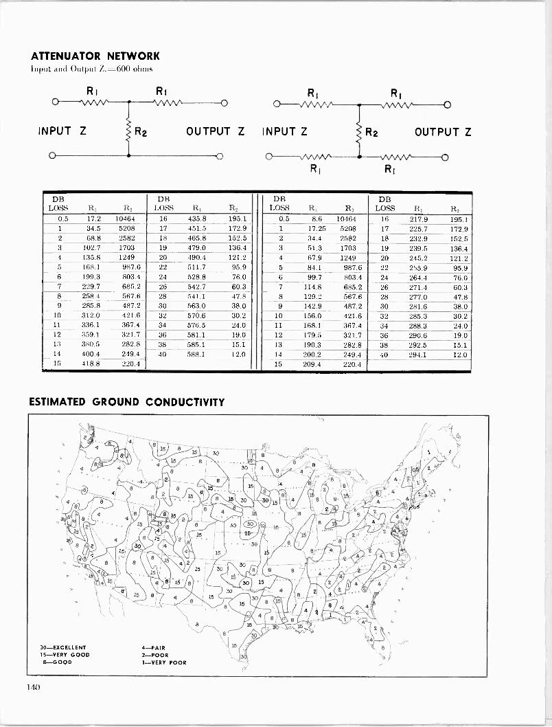
ATTENUATOR Input and Output Z.
Ri
INPUT Z
NETWORK =600 ohms
Ri
OUTPUT Z INPUT Z OUTPUT Z
DB LOSS R1 R2
DB LOSS R1 R2
DB LOSS R1 R2
DB LOSS R1 R2
0.5 17.2 10464 16 435.8 195.1 0.5 8.6 10464 16 217.9 195.1 1 34.5 5208 17 451.5 172.9 1 17.25 5208 17 225.7 172.9 2 68.8 2582 18 465.8 152.5 2 34.4 2582 18 232.9 152.5 3 102.7 1703 19 479.0 136.4 3 51.3 1703 19 239.5 136.4 4 135.8 1249 20 490.4 121.2 4 67.9 1249 20 245.2 121.2 5 168.1 987.6 22 511.7 95.9 5 84.1 987.6 22 255.9 95.9 6 199.3 803.4 24 528.8 76.0 6 99.7 803.4 24 264.4 76.0 7 229.7 685.2 26 542.7 60.3 7 114.8 685.2 26 271.4 60.3 8 258.4 567.6 28 541.1 47.8 8 129.2 567.6 28 277.0 47.8 9 285.8 487.2 30 563.0 38.0 9 142.9 487.2 30 281.6 38.0
10 312.0 421.6 32 570.6 30.2 10 156.0 421.6 32 285.3 30.2 11 336.1 367.4 34 576.5 24.0 11 168.1 367.4 34 288.3 24.0 12 359.1 321.7 36 581.1 19.0 12 179.5 321.7 36 290.6 19.0 13 380.5 282.8 38 585.1 15.1 13 190.3 282.8 38 292.5 15.1 14 400.4 249.4 40 588.1 12.0 14 200.2 249.4 40 294.1 12.0 15 418.8 220.4 15 209.4 220.4
ESTIMATED GROUND CONDUCTIVITY
1 10
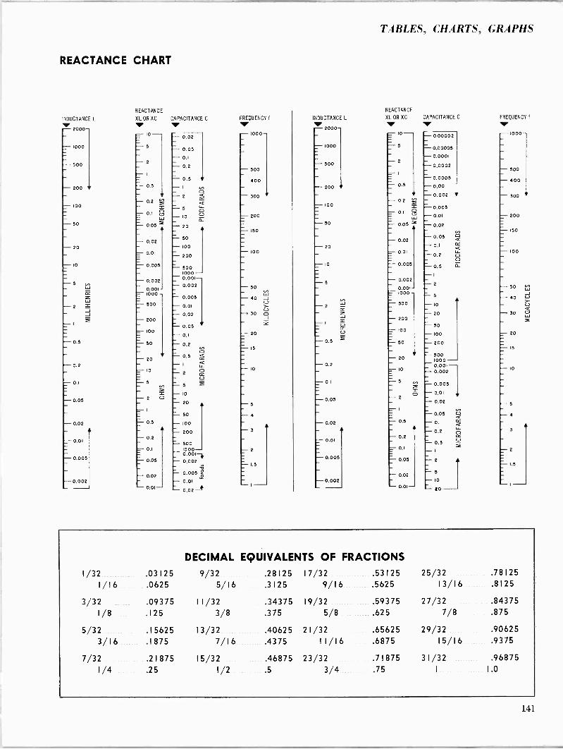
TABLES, CHARTS, GRAPHS
REACTANCE CHART
INDUCTANCE L - 2000-
- 1000
- - 500
- 200
- 100
- - 50
- 20
- 10
- 5
- 2
- 0.5
- 0.2
- 0.05
- 0.02
- 0.01
- 0.005
- 0.002
REACTANCE
XL OR XC CAPACITANCE C
10- z
- 2 - 1
- 0.5
- 0.2
- 0.1 c.7 = w _ 0.05
- 0.02
- 0.01
- 0.005
- 0.002
0,001 - 1000 - 500
- 200
- 100
= 50
- 20
- IO
^ 5
- - 2 Ó
- - 0.5
_ - 0.2
- 0.1
- 0.05
- 0.02
- 0.01-
- 0.02
- 0.05 - 0.1 - 0.2
- 0.5 - 1 - 2
- 5 - 10 - 20
50 - 100 - 200
- 500 1000 - 0.001- - 0.002
- 0.005
0.01 - 0.02
0.05 - 0.1
- 0.2
0.5 - I - 2
5 - 10 - 20
50 - 100 - 200
500 1000- 0.001-i - 0.002
0.005 e
- 0.01 W
- 0.02 -+
FREQUENCY f
111, - 1000-
- 500 - 400
- 300
- 200
- ISO
- 100
- 50 - 40
- 30
- 20
-- 15
- 10
- 5
- 4
- 3
- 2
1.5
REACTANCE
INDUCTANCE L XL OR XC CAPACITANCE C - z000-
- 1000
- 500
200
- 100
- 50
- 20
- 10
-5
- 2
- 1
- - 0.5
- 0.2
- 0.1
- 0.05
- 0.02
- 0.01
- - 0.005
- 0.002
- Io - -5 - 2
I
- 0.1 8 Lu - 0.05
- 0.02
- 0.01
- - 0.005
- 0.002
0.001 - 1000
^ 500
- 200 - 100
- 50
- 20
- IO
0.1
- 0.05
- 0.02
- 0.01-
- 0,00002
- 0.00005 - 0.0001 - 0,0002
- 0.0005 - 0,001 - 0.002
0.005 - 0.01 - 0.02
- 0.05 - 0.1 - 0.2 - 0.5 - 1 - - z
- 5 - 10 - 20
- 50 - 100 - 200
- 500 1000 - 0.001 - 0.002
- 0.005 - 0.01 - 0.02
- - 0.05 - 0.1 - 0.2
- 0.5 - I
2
5
IO - 20
FREQUENCY f
- 1000-
- 500 - 400
- 300
- 200
- 150
- 100
- 50 - 40
30
- 20
- 15
- IO
-5 - 4
- 3
- 2
1.5
DECIMAL EQUIVALENTS OF FRACTIONS
1/32 .03125 9/32 .28125 17/32 .53125 25/32 .78125 1/16 .0625 5/16 .3125 9/16 .5625 13/16 .8125
3/32 .09375 11/32 .34375 19/32 .59375 27/32 .84375 1/8 .125 3/8 .375 5/8 .625 7/8 .875
5/32 .15625 13/32 .40625 21/32 .65625 29/32 .90625 3/16 .1875 7/16 .4375 11/16 .6875 15/16 .9375
7/32 .21875 15/32 .46875 23/32 .71875 31/32 .96875 1/4 .25 1/2 .5 3/4 _ .75 I 1.0
141

ATTENUATION EXPRESSED AS EFFICIENCY
i
xi r
III Ill: . 11 Ì I ï.I._ ®
L +WWI
111111111M011 1 :
-l=
-r
10
Efficiency in Percent
DETERMINATION OF OVERALL TRANSMISSION LINE EFFICIENCY
To obtain total loss in a given transmission line, multiply the attenuation in db per 100 ft. by the number of 100 foot lengths of line to be used. By referring to the curve on this page, the overall transmission efficiency may be determined.
100
112
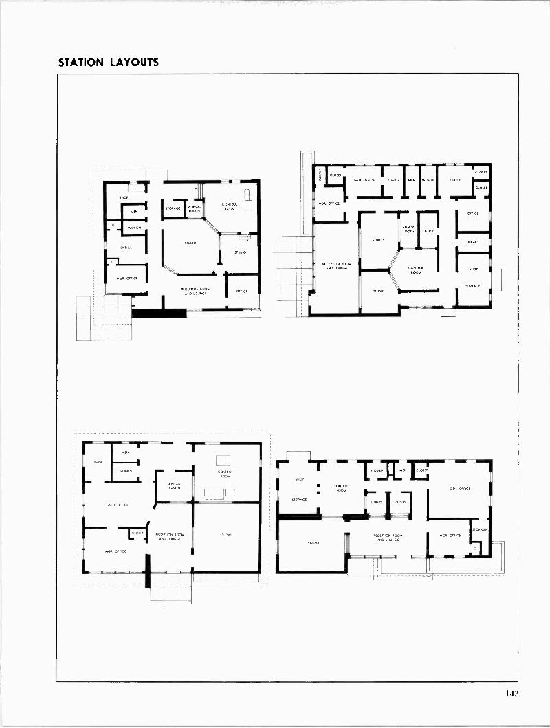
STATION LAYOUTS
MEN
WOMEN
OFFICE
RECEPTION ROOM ANO LOUNGE
M.
OMEN
GEN. OFFICE
CLOSET
MGR. OFFICE
CONTROL
ROOM [I]
OFPCE
CONTRO ROOM
RECEPTION ROOM
AND LOUNGE STUDIO
SHOP
STORAGE
GEN. OFFICF
MGR. OFFIC
uEry W _MCN OFFICE
73C, OFFICE
` STUDIO
RECEPTION ROOM
AND LOUNGE
CONTROL
ROOM
STUDIO
STUDIO
CONTROL ROOM
WOMEN MEN CLOSET
STUDIO ISTI RS
CLOSET
CLOSET
OFFICE
BR
L
GEN. OFFICE
STORAGE
RECEPTION ROOM MGR. OFFICE
AND LOUNGE
143
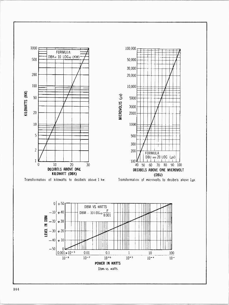
1000
500
200
100
50
20
10
5
2
1
FORMULA:
DBK= 10 LOGE) (KW)
10 20 30
DECIBELS ABOVE ONE
KILOWATT (DBK)
Transformation of kilowatts to decibels above 1 kw.
0
m
-10
m c -20 z -30
L.,,' J - 40
- 50
100,000
50,000
30,000
20,000
10,000
5000
3000
2000
1000
500
300
200
100 40 50 60 70 80 90 100
DECIBELS ABOVE ONE MICROVOLT
(DBU)
Transformation of microvolts to decibels above 1uv.
FORMULA
DBU = 20 LOG (Ay) 11111 I1
+ 5U
D B M VS WATTS
P +40 DBM 10 LOGIo 0.001
+30
+20
+10
0
0.001=10-3 001 0.1 1 10 10
10-8 10-7 10-6
POWER IN WATTS
Dbm vs. watts.
10-5 10-a
0
10-
144
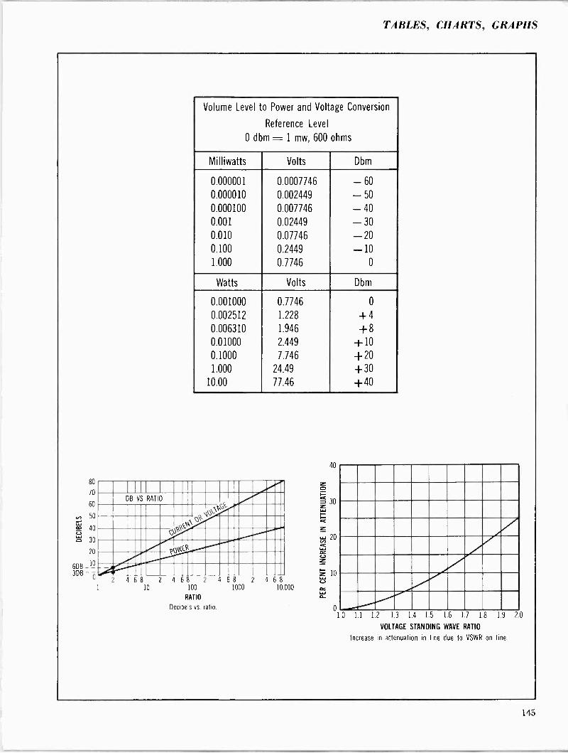
TABLES, CHARTS, GRAPHS
80
70
60
50 J m 40
ó 30
20
6DB_10 3DB -
Volume Level to Power and Voltage Conversion
Reference Level
0 dbm - 1 mw, 600 ohms
Milliwatts Volts Dbm
0.000001 0.0007746 - 60
0.000010 0.002449 - 50
0.000100 0.007746 - 40
0.001 0.02449 - 30
0.010 0.07746 -20 0.100 0.2449 -10 1.000 0.7746 0
Watts Volts Dbm
0.001000 0.7746 0
0.002512 1.228 + 4
0.006310 1.946 +8 0.01000 2.449 +10 0.1000 7.746 +20 1.000 24.49 +30
10.00 77.46 +40
2 4 68 10
2 4 68 2
100
RATIO
Decibels vs ratio.
4 68 2
1000
4 68 10.000
40
11 1.2 13 14 1.5
VOLTAGE STANDING
16 1.7 18 19 20
WAVE RATIO
Increase in attenuation in line due to VSWR on line.
145
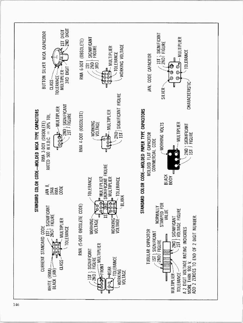
Ó F- 1=1 0 p C/)ZCr Lab
.-4 CV Cr)
Q Cr
Q O ¢ O - -- CL
Cr w_ J Cà -
__J
::2
:äE
Úg: J = " Q C23 C23 I F-
U N W p r-'`"-, CL W .-' N
>- C:2J O m CY]
146

"r1 RLFti, G/{.-1P11,ti
M
CJ Cr CC LLJ O 0 0 0 0 0 0 0 0 Z O W Z O O O O O O O O J J O O O O O O O O O a Z 0 0 0 0 0 O.
CZ O O O O O U
F- O O O O CC O Ó Ó O - = p O
Or -A N Mst LC) CO CO OD
N re) l2") CO n CO CT)
LU Y Z U p Z W LU OJ Q O p Q w= - Q F-
--i CC LLJ Cr W Cr J _O CC2 OU CO mC:C 0>- C7 m>. C7
147
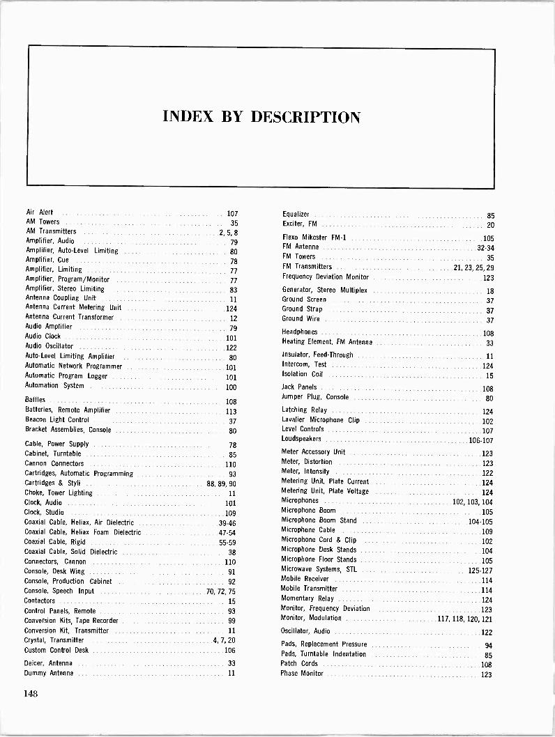
INDEX BY DESCRIPTION
Air Alert
AM Towers
AM Transmitters
Amplifier, Audio Amplifier, Auto -Level Limiting Amplifier, Cue
Amplifier, Limiting
107
35
2, 5, 8
79
80
78
77
Equalizer
Exciter, FM
Flexo Mikester FM -1
FM Antenna
FM Towers
FM Transmitters
85
20
105
32-34
35
21, 23, 25, 29
Amplifier, Program/Monitor 77 Frequency Deviation Monitor 123
Amplifier, Stereo Limiting 83 Generator, Stereo Multiplex 18 Antenna Coupling Unit 11 Ground Screen 37 Antenna Current Metering Unit 124 Ground Strap 37 Antenna Current Transformer 12 Ground Wire 37 Audio Amplifier Audio Clock
Audio Oscillator
79
101
122
Headphones
Heating Element, FM Antenna 108
33
Auto -Level Limiting Amplifier 80 Insulator, Feed -Through 11
Automatic Network Programmer 101 Intercom, Test 124
Automatic Program Logger 101 Isolation Coil 15
Automation System 100 Jack Panels 108
Baffles 108 Jumper Plug, Console 80
Batteries, Remote Amplifier 113 Latching Relay 124 Beacon Light Control 37 Lavalier Microphone Clip 102 Bracket Assemblies, Console 80 Level Controls 107
Cable, Power Supply 78 Loudspeakers 106-107
Cabinet, Turntable 85 Meter Accessory Unit 123
Cannon Connectors 110 Meter, Distortion 123
Cartridges, Automatic Programming 93 Meter, Intensity 122
Cartridges & Styli 88, 89, 90 Metering Unit, Plate Current 124
Choke, Tower Lighting 11 Metering Unit, Plate Voltage 124
Clock, Audio 101 Microphones 102, 103, 104
Clock, Studio 109 Microphone Boom 105
Coaxial Cable, Heliax, Air Dielectric 39-46 Microphone Boom Stand 104-105
Coaxial Cable, Heliax Foam Dielectric 47-54 Microphone Cable 109
Coaxial Cable, Rigid 55-59 Microphone Cord & Clip 102
Coaxial Cable, Solid Dielectric 38 Microphone Desk Stands 104
Connectors, Cannon 110 Microphone Floor Stands 105
Console, Desk Wing 91 Microwave Systems, STL 125-127
Console, Production Cabinet 92 Mobile Receiver 114
Console, Speech Input 70,72,75 Mobile Transmitter 114
Contactors 15 Momentary Relay 124
Control Panels, Remote 93 Monitor, Frequency Deviation 123
Conversion Kits, Tape Recorder 99 Monitor, Modulation 117, 118, 120, 121
Conversion Kit, Transmitter 11 Oscillator, Audio 122 Crystal, Transmitter
Custom Control Desk
4,7,20 106
Pads, Replacement Pressure
Pads, Turntable Indentation
94
85
Deicer, Antenna 33 Patch Cords 108 Dummy Antenna 11 Phase Monitor 123
148
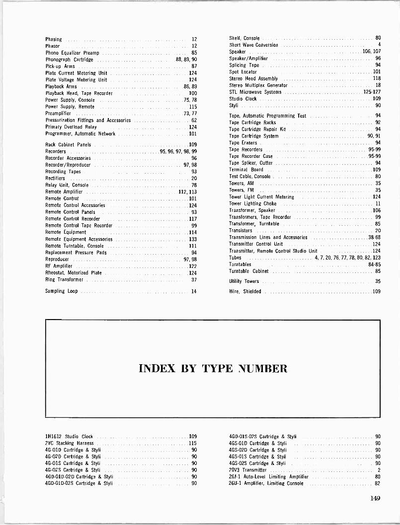
Phasing
Phasor 12
Phono Equalizer Preamp 85
Phonograph Cartridge 88, 89, 90
Pick-up Arms 87
Plate Current Metering Unit 124
Plate Voltage Metering Unit 124
Playback Arms 86,89 Playback Head, Tape Recorder 100
Power Supply, Console 75, 78
Power Supply, Remote 115
Preamplifier 73, 77
Pressurization Fittings and Accessories 62
Primary Overload Relay 124
Programmer, Automatic Network 101
Rack Cabinet Panels 109
Recorders 95, 96, 97, 98, 99
Recorder Accessories 96
Recorder/Reproducer 97,98 Recording Tapes 93
Rectifiers 20
Relay Unit, Console
Remote Amplifier 112, 113
Remote Control 101
Remote Control Accessories 124 Remote Control Panels 93
Remote Control Recorder 117
Remote Control Tape Recorder 99
Remote Equipment 114
Remote Equipment Accessories 133
Remote Turntable, Console 111
Replacement Pressure Pads 94
Reproducer 97, 98
RF Amplifier 122
Rheostat, Motorized Plate 124
Ring Transformer 37
Sampling Loop
12 Shelf, Console 80
Short Wave Conversion 4
Speaker 106, 107
Speaker/Amplifier 96
Splicing Tape 94
Spot Locator 101
Stereo Head Assembly 118
Stereo Multiplex Generator 18
STL Microwave Systems 125-127
Studio Clock 109
Styli 90
Tape, Automatic Programming Test 94
Tape Cartridge Racks 92
Tape Cartridge Repair Kit 94
Tape Cartridge System 90, 91
Tape Erasers 94
Tape Recorders 95-99
Tape Recorder Case 95-99
Tape Splicer, Cutter 94
Terminal Board 109
Test Cable, Console 80
78 Towers, AM 35
Towers, FM 35
Tower Light Current Metering 124
Tower Lighting Choke 11
Transformer, Speaker 106
Transformers, Tape Recorder 99
Transformer, Turntable 85 Transistors 20 Transmission Lines and Accessories 38-68 Transmitter Control Unit 124
Transmitter, Remote Control Studio Unit 124
Tubes 4, 7, 20, 76, 77, 78, 80, 82, 123
Turntables 84-85 Turntable Cabinet 85
Utility Towers 35
14 Wire, Shielded 109
INDEX BY TYPE NUMBER
1H1612 Studio Clock 109 4GD-O1S-02S Cartridge & Styli 90
2YC Stacking Harness 115 4GS-01D Cartridge & Styli 90
4G -01D Cartridge & Styli 90 4GS-02D Cartridge & Styli 90
4G-O2D Cartridge & Styli 90 4GS-01S Cartridge & Styli 90 4G-015 Cartridge & Styli 90 4GS-02S Cartridge & Styli 90
4G-O2S Cartridge & Styli 90 20V3 Transmitter 2
4GD-01D-02D Cartridge & Styli 90 26J-1 Auto -Level Limiting Amplifier 80 4GD-01D-02S Cartridge & Styli 90 26U-1 Amplifier, Limiting Console 82
149
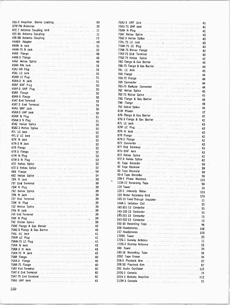
26U-2 Amplifier, Stereo Limiting 37M FM Antennas
42E-7 Antenna Coupling Unit 42E -8A Antenna Coupling
42E -8B Antenna Coupling 44AGR Adapter
44AN N Jack
44AN-75 N Jack
44AR Flange
44AR-3 Flange
44AZ Heliax Splice
45AH HN Jack
45M HN Plug
45AL LC Jack
45AM LC Plug
45AN-3 N Jack
45AP UHF Plug
45AP-3 UHF Plug
45AR Flange
45AR-3 Flange
45AT End Terminal
45AT-3 End Terminal 45AU UHF Jack
45AU-3 UHF Jack
45AW N Plug
45AW-3 N Plug 45AZ Heliax Splice
45AZ-3 Heliax Splice 47L LC Jack
47L-3 LC Jack
47N N Jack
47N-3 N Jack
47R Flange
47R-3 Flange
47W N Plug
47W-3 N Plug
47Z Heliax Splice
47Z-3 Heliax Splice
48R Flange
48Z Heliax Splice
71N N Jack
71T End Terminal
71W N Plug
71Z Heliax Splice
72N N Jack
72T End Terminal
72W N Plug
72Z Heliax Splice
74N N Jack
74T End Terminal
74W N Plug
74Z Heliax Splice
75AG Flange & Gas Barrier 75AG-3 Flange & Gas Barrier 75AL LC Jack
75AM LC Plug
75AM-75 LC Plug
75AN N Jack
75AN-3 N Jack
75AN-75 N Jack
75AR Flange
75AR-3 Flange
75AR-75 Flange
75AT End Terminal 75AT-3 End Terminal
75AT-75 End Terminal
75AU UHF Jack
75AU-3 UHF Jack 41 75AU-75 UHF Jack 41 75AW N Plug 41 75AZ Heliax Splice 40 75AZ-3 Heliax Splice 40 77AL-75 LC Jack 43 77AM-75 LC Plug 43 77AR-75 Heliax Flange 42 77AT-75 End Terminal 43 77AZ-75 Heliax Splice 42 78G Flange & Gas Barrier 44 78G-75 Flange & Gas Barrier 44 78L LC Jack 45 78R Flange 44 78R-75 Flange 44 78S Connector 44 78S-75 Reducer Connector 44 78Z Heliax Splice 45 78Z-75 Heliax Splice 45 79G Flange & Gas Barrier 46 79R Flange 46 79Z Heliax Splice 46 81M Phasor 12 87G Flange & Gas Barrier 42
87G-3 Flange & Gas Barrier 42 87L LC Jack 43 87M LC Plug 43 87N N Jack 43 87R Flange 42 87R-3 Flange 42 87S Connector 42 87T End Terminal 43 87U UHF Jack 43 87Z Heliax Splice 42 87Z-3 Heliax Splice 42 91 Tape Recorder 99 92 Tape Recorder 99 93 Tape Recorder 99 93-4 Tape Recorder 99 108-E Phase Monitors 123 111A-12 Recording Tape 94
120 Tower 35 120-E Intensity Meter 123 121 Meter Accessory Unit 123 135-15 Feed-Thorugh Insulator 11 144A-1 Isolation Coil 15 145-101-13 Contactor 15 145-102-13 Contactor 15 145.201-13 Contactor 15 145-202-13 Contactor 15 150-18 Recording Tape 94
156 Headphones 108 157 Headphones 108 17OKD Tower 35 172G-1 Dummy Antenna 11 172G-2 Dummy Antenna 11 180 Tower 35 190-18 Recording Tape 94
2O0C Tape Eraser 94
208-S Playback Arm 87
208 -SG Playback Arm 87
210 Audio Oscillator 122
212G-1 Console 75
212H-1 Remote Amplifier 112 212M-1 Console 72
150
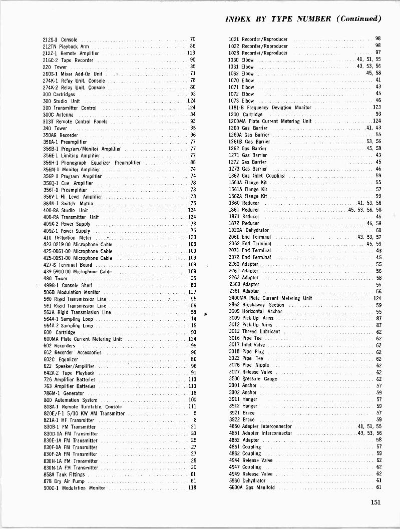
INDEX BY TYPE NUMBER (Continued)
212S-1 Console 70 1021 Recorder/Reproducer 98
212TN Playback Arm 86 1022 Recorder/Reproducer 98
212Z-1 Remote Amplifier 113 1028 Recorder/Reproducer 97
216C-2 Tape Recorder 90 1060 Elbow 41, 51, 55
220 Tower 35 1061 Elbow 43, 53, 56
260S-1 Mixer Add -On Unit 71 1062 Elbow 45, 58
274K-1 Relay Unit, Console 78 1070 Elbow 41
274K-2 Relay Unit, Console 80 1071 Elbow 43
300 Cartridges 93 1072 Elbow 45
300 Studio Unit 124 1073 Elbow 46
300 Transmitter Control 124 1181-B Frequency Deviation Monitor 123
300C Antenna 34 1200 Cartridge 93
313T Remote Control Panels 93 1200MA Plate Current Metering Unit 124
340 Tower 35 1260 Gas Barrier 41, 43
350AG Recorder 96 1260A Gas Barrier 55
356A-1 Preamplifier 77 1261B Gas Barrier 53, 56
3566-1 Program/Monitor Amplifier 77 1262 Gas Barrier 45, 58
356E-1 Limiting Amplifier 77 1271 Gas Barrier 43
356H-1 Phonograph Equalizer Preamplifier 86 1272 Gas Barrier 45
356M-1 Monitor Amplifier 74 1273 Gas Barrier 46
356P-1 Program Amplifier 74 1362 Gas Inlet Coupling 59
356Q-1 Cue Amplifier 78 1560A Flange Kit 55
356T-1 Preamplifier 73 1561A Flange Kit 57
356V-1 Hi Level Amplifier 73 1562A Flange Kit 59
384D-1 Switch Matrix 75 1860 Reducer 41, 53, 56
400 -RA Studio Unit 124 1861 Reducer 45, 53, 56, 58
400 -RA Transmitter Unit 124 1871 Reducer 45
409X-2 Power Supply 78 1872 Reducer 46, 58
409Z-1 Power Supply 75 1920A Dehydrator 60
410 Distortion Meter 123 2061 End Terminal 43, 53, 57
423-0219-00 Microphone Cable 109 2062 End Terminal 45, 59
425-0061-00 Microphone Cable 109 2071 End Terminal 43
425-0151-00 Microphone Cable 109 2072 End Terminal 45
427-6 Terminal Board 109 2260 Adapter 55
439-5900-00 Microphone Cable 109 2261 Adapter 56
480 Tower 35 2262 Adapter 58
499G-1 Console Shelf 80 2360 Adapter 55
5066 Modulation Monitor 117 2361 Adapter 56
560 Rigid Transmission Line 55 2400MA Plate Current Metering Unit 124
561 Rigid Transmission Line 56 2962 Breakaway Section 59
562A Rigid Transmission Line 58 a 3009 Horizontal Anchor 55
564A-1 Sampling Loop 14 3009 Pick -Up Arms 87
564A-2 Sampling Loop 15 3012 Pick -Up Arms 87
600 Cartridge 93 3012 Thread Lubricant 62
600MA Plate Current Metering Unit 124 3016 Pipe Tee 62
602 Recorders 95 3017 Inlet Valve 62
602 Recorder Accessories 96 3018 Pipe Plug 62
602C Equalizer 86 3022 Pipe Tee 62
622 Speaker/Amplifier 96 3026 Pipe Nipple 62
642A-2 Tape Playback 91 3027 Release Valve 62
726 Amplifier Batteries 113 3500 eressure Gauge 62
763 Amplifier Batteries 113 3901 Anchor 57
786M-1 Generator 18 3902 Anchor 59
800 Automation System 100 3911 Hanger 57
808A-1 Remote Turntable, Console 111 3912 Hanger 59
820E/F-1 5/10 KW AM Transmitter 5 3921 Brace 57
821A-1 HF Transmitter 8 3922 Brace 59
830B-1 FM Transmitter 21 4850 Adapter Interconnector 41, 51, 55
830D -1A FM Transmitter 23 4851 Adapter Interconnector 43, 53, 56
830E -1A FM Transmitter 25 4852 Adapter 58
830F -1A FM Transmitter 27 4861 Coupling 57
830F -2A FM Transmitter 27 4862 Coupling 59
830H -1A FM Transmitter 29 4944 Release Valve 62
830N -1A FM Transmitter 30 4947 Coupling 62
858A Tank Fittings 61 4949 Release Valve 62
878 Dry Air Pump 61 5960 Dehydrator 61
900C-1 Modulation Monitor 118 6600A Gas Manifold 61
151

8412 Microphone Cable
8422 Microphone Cable
8738 Microphone Cable
8758 Microphone Cable
9905-18 Vinyl Tape
10195 Hose Assembly
109
109
109
109
62
62
24444 Interconnector
24530 Adapter
24622 Hanger
24810-1/2/3 Ground Kit
24811-1/2/3/4 Ground Kit 25385 Interconnector
43,
41,
43,
45
45
53
51
53
41 10683-2 0 -Ring Gasket 57 25388 Interconnector 41
10683-3 0 -Ring Gasket 59 25435 Tubing 62
10741-2 Copper Tubing 62 25436-4 Elbow 62
10804-4 N Panel Receptacle 38 25436-12 Pipe Nipple 62 10804-9 N Junction 38 25572 Adapter 43 10804-10 N Right Angle Connector 38 26666 Reducer Connector 44
10804-11 N Junction 38 26892-1/2/4 Grounding Kit 49 10804-34 N Cable Jack 38 26985 Hoisting Kit 45 10804-36 N Cable Plug 38 27290 Copper Weld Tie Wire 39, 47, 49, 51
10805-1 UHF Cable Plug 38 28708-1 Grounding Kit 45 10805-4 UHF Tee Connector 38 28708-2 Grounding Kit 45 10805-5 UHF Right Angle Connector 38 29958 Cable Grip 41, 51
10805-6 UHF Junction 38 30079 Connectors 58 10805-11 Adapter, UHF Jack 38 30417-1 Grounding Kit 46 10805-12 Adapter, UHF Plug 38 30417-2 Grounding Kit 46 10994-2 Coupling 62 30452 Adapter 57
10994-4 Coupling 62 31031 Cable Grip 46 11381-2 Hardware Kit 57 31614 Regulating Tank 60 11381-3 Hardware Kit 59 31616 Humidity Sensor 60 11662-2 Insulated Mounting Clamp 41, 51 31618 Pressure Sensor 60 11662-3 Insulated Mounting Clamp 39, 49 31680-1/2 Connector 62 12129 Sleeve 62 31680-3/5 Tee Connector 62 12395-1 Wraplock 33, 39, 41, 47, 49, 53 31712 Strap 62 12418-1 LC Cable Plug 38 63305 -DB Beacon Light Control 37 12418-3 LC Junction 38 700105 Transformer 99 12418-5 N Cable Plug 38
700106 Transformer 99 12418-12 UHF Cable Plug 38
700107 Transformer 99 12430-1 Ground Clamp 57
700108 Transformer 99 12431 Ground Clamp
13550 Hanger Adapter
13552 Spacer
45,
59
59
57
700120 Remote Control, Tape Recorder
700122 Tape Recorder Case
99
99
13555 Hanger Adapter 45, 55, 59 700133 Tape Recorder Case 99
13889 Spring Hanger 55 A830-2 FM Exciter 20
13924 Rigid Hanger 57 A-3818 Speaker Transformer 107
13925 Spring Hanger 59 AC -100 Antenna Current Metering Unit 124
13926 Spring Hanger 59 AG -350-1 Mono Record/Reproducer 97
13927 Rigid Hanger 45, 59 AG -350-2 Stereo Record/Reproducer 97
14063 Insulator 57, 59 AG -355-1 Mono Reproducer 97
14327 Sliding Hanger 55 AG -355-2 Stereo Reproducer 97
14328 Rigid Hanger 55 ANP-1 Automatic Network Programmer 101
14379 Sliding Hanger 57 APL -1 Automatic Program Logger 101
14387 Sliding Hanger 57 ASP -143 Bumper Mount 115
14441 Sliding Hanger 57 ASP -177 Antenna 115
14442 Sliding Hanger 57 BA -200 Headphones 108
15069 Connector 43, 53, 56 BA -206 Headphones 108
15093 Connector 45, 59 BB -1 Microphone Boom 105
15840 Flange Kit 59 6X801 Tape Recorder 99
16253 Jumper Cable 49 BX822 Tape Recorder 99
18041 Flange Kit 57 CR -1773-B Rack Cabinet 109
18096 Flange Kit 55 CS -12 Loudspeaker 106
18200 Flange Kit 59 DS -7 Microphone Desk Stand 104
18275 Connector 41, 51, 55 DWW-3 Desk Wing Console 91
18630 Flange Kit 55 FM -1 Flexo Mikester 105
18631 Flange Kit 57 GR -6355 Connector 115
19209B Flexible Section 59 HI -50 Heliax Cable 39
19256A Hoisting Kit 41, 51 H2-50 Heliax Cable 39
20695 Flexible Section 57 H4-50 Heliax Cable 39
22418 Hanger 45 H5-50 Heliax Cable 40
23187 Adapter 45 H5-75 Heliax Cable 40
24254 Interconnector 43 H7 -50A Heliax Cable 42
24312 Hoisting Kit 43, 53 H7-75 Heliax Cable 42
152
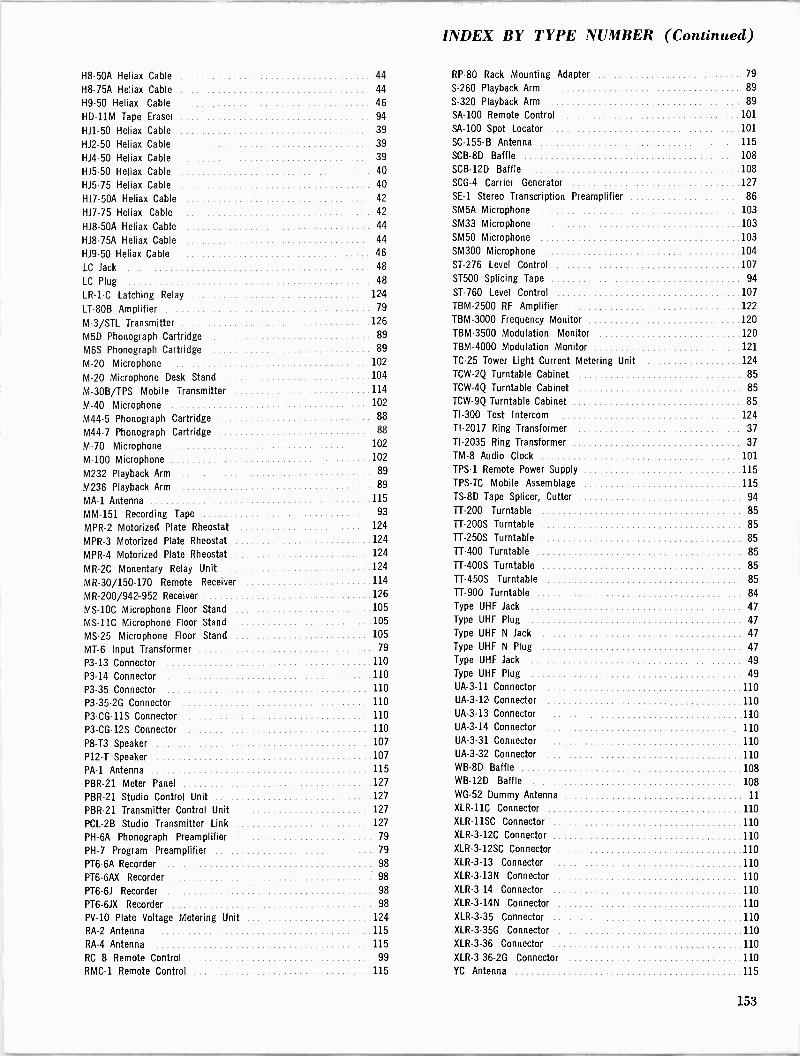
INDEX BY TYPE NUMBER (Continued)
H8 -50A Heliax Cable 44 RP -80 Rack Mounting Adapter 79
H8 -75A Heliax Cable 44 S-260 Playback Arm 89
H9-50 Heliax Cable 46 S-320 Playback Arm 89
HD -11M Tape Eraser 94 SA -100 Remote Control 101
H11-50 Heliax Cable 39 SA -100 Spot Locator 101
HJ2-50 Heliax Cable 39 SC -155-B Antenna 115
HJ4-50 Heliax Cable 39 SCB-8D Baffle 108
H15-50 Heliax Cable 40 SCB-12D Baffle 108
HJ5-75 Heliax Cable 40 SCG-4 Carrier Generator 127
H17.50A Heliax Cable 42 SE -1 Stereo Transcription Preamplifier 86
H17-75 Heliax Cable 42 SM5A Microphone 103
H18 -50A Heliax Cable 44 SM33 Microphone 103
H18 -75A Heliax Cable 44 SM50 Microphone 103
H19-50 Heliax Cable 46 SM300 Microphone 104
LC Jack 48 ST -276 Level Control 107
LC Plug 48 ST500 Splicing Tape 94
LR -1-C Latching Relay 124 ST -760 Level Control 107
LT -80B Amplifier 79 TBM-2500 RF Amplifier 122
M-3/STL Transmitter 126 TBM-3000 Frequency Monitor 120
M5D Phonograph Cartridge 89 TBM-3500 Modulation Monitor 120
M6S Phonograph Cartridge 89 IBM -4000 Modulation Monitor 121
M-20 Microphone 102 TC -25 Tower Light Current Metering Unit 124
M-20 Microphone Desk Stand 104 TCW-2Q Turntable Cabinet 85
M-30B/TPS Mobile Transmitter 114 TCW-4Q Turntable Cabinet 85
M-40 Microphone 102 TCW-9Q Turntable Cabinet 85
M44-5 Phonograph Cartridge 88 TI -300 Test Intercom 124
M44-7 Phonograph Cartridge 88 TI -2017 Ring Transformer 37
M-70 Microphone 102 TI -2035 Ring Transformer 37
M-100 Microphone 102 TM -8 Audio Clock 101
M232 Playback Arm 89 TPS-1 Remote Power Supply 115
M236 Playback Arm 89 TPS-TC Mobile Assemblage 115
MA -1 Antenna 115 TS -8D Tape Splicer, Cutter 94
MM -151 Recording Tape 93 TT -200 Turntable 85
MPR-2 Motorized Plate Rheostat 124 7-200S Turntable 85
MPR-3 Motorized Plate Rheostat 124 TT -250S Turntable 85
MPR-4 Motorized Plate Rheostat 124 7-400 Turntable 85
MR -2C Monentary Relay Unit 124 TT -400S Turntable 85
MR -30/150-170 Remote Receiver 114 7-450S Turntable 85
MR -200/942952 Receiver 126 TT -900 Turntable 84
MS -10C Microphone Floor Stand 105 Type UHF Jack 47
MS -11C Microphone Floor Stand 105 Type UHF Plug 47
MS -25 Microphone Floor Stand 105 Type UHF N Jack 47
MT -6 Input Transformer 79 Type UHF N Plug 47
P3-13 Connector 110 Type UHF Jack 49
P3-14 Connector 110 Type UHF Plug 49
P3-35 Connector 110 UA -3-11 Connector 110
P3 -35-2G Connector 110 UA -3-12 Connector 110
P3 -CG -11S Connector 110 UA -3-13 Connector 110
P3 -CG -12S Connector 110 UA -3-14 Connector 110
P8 -T3 Speaker 107 UA -3-31 Connector 110
P12 -T Speaker 107 UA -3-32 Connector 110
PA -1 Antenna 115 WB -8D Baffle 108
PBR-21 Meter Panel 127 WB -12D Baffle 108
PBR-21 Studio Control Unit 127 WG -52 Dummy Antenna 11
PBR-21 Transmitter Control Unit 127 XLR-11C Connector 110
PCL-2B Studio Transmitter Link 127 XLR-11SC Connector 110
PH -6A Phonograph Preamplifier 79 XLR-3-12C Connector 110
PH -7 Program Preamplifier 79 XLR-3-12SC Connector 110
PT6-6A Recorder 98 XLR-3-13 Connector 110
PT6-6AX Recorder 98 XLR-3-13N Connector 110
P16-61 Recorder 98 XLR-3-14 Connector 110
PT6-61X Recorder 98 XLR-3-14N Connector 110
PV -10 Plate Voltage Metering Unit 124 XLR-3-35 Connector 110
RA -2 Antenna 115 XLR-3-35G Connector 110
RA -4 Antenna 115 XLR-3-36 Connector 110
RC 8 Remote Control 99 XLR-3-36-2G Connector 110
RMC-1 Remote Control 115 YC Antenna 115
153
COLLINS BROADCAST
COMMUNICATION
SALES POLICY
HOW TO ORDER
This catalog has been prepared to make it possible for you to order directly from the Collins Broadcast Com- munication Division or your Collins Broadcast Sales En- gineer with a minimum of effort and maximum assurance that you will receive the best equipment available. Collins type numbers and part numbers are listed so that you may order by mail, if you wish, and receive the same fast, personal service that is available from your Collins Broadcast Sales Engineer.
PRICES
Prices in the price book inside the back cover replace all previous prices and are subject to change without no-
tice. Orders are filled at prices in effect at the time of
shipment. If prices are reduced, you receive the advan- tage of the lower price. Collins customers outside the 50
United States should contact Collins Radio Company, International Division, Dallas, Texas, or Collins Radio Company of Canada, Ltd., Toronto 16, Ontario.
SIGNED ORDERS
All orders must be signed by an officer of the purchasing corporation, partnership or company. All orders, down
payment agreements and terms are subject to final accept- ance at the Collins Broadcast Sales Division office in
Dallas, Texas.
SUBSTITUTION AND MODIFICATION Collins reserves the right to modify, without notice, the design and specifications of equipment designed by Col-
lins.
TERMS OF SALE
Terms of payment for all Collins Radio Company broad- cast equipment sales fall into the following categories:
1. Cash in advance or C.O.D.
2. Net 30 days.
3. 30-60.90 days (no interest or carrying charge).
4. Conditional Sales Contract.
154
I IlMil 11
DOWN PAYMENT
On all firm orders applicable to Conditional Sales Con-
tracts, a minimum down payment of 25% is required, with the balance spread equally. In the case of contingent orders, a minimum of 3% down is required.
SHIPMENT
In the absence of specific instructions Collins will select
the carrier to whom delivery will be made for shipment to the purchaser.
DAMAGES IN SHIPPING
Usually, shipments from Collins Radio Company or one of its vendors on a drop ship basis are made "Shipping Charges Collect." As such, the equipment automatically becomes the property of the purchaser when picked up by the carrier. Should damage occur during shipment, the request for inspection and claims for damage must be made by the purchaser with reimbursement paid di-
rectly to him. Collins will gladly assist the purchaser with any necessary information he may require to suc-
cessfully negotiate a claim.
DELIVERY
Unless otherwise specified, delivery will be made f.o.b. from one of Collins' various shipping points or from the shipping point of a supplier of Collins. Although Collins makes every effort to expedite shipments, the Company cannot guarantee nor be held responsible for delays in shipments caused by a supplier of Collins or by the car- rier.
FIELD SERVICE
Fast field service is assured owners of Collins broadcast equipment by the Collins Service Division. A staff of se-
lected specialists is maintained to provide Collins custom- ers a level of service consistent with high performance equipment. For service on Collins equipment which is es-
sential to continued on -the -air operations of the station, contact your Collins Broadcast Sales Engineer. For emer- gency, after-hours service, Call Dallas, Texas, 214 AD 5-9511. Collins field service engineers are stationed at key points throughout the world. Overseas customers contact your nearest International office.
RETURNING GOODS All returned goods, whether for repair, replacement or credit. must be authorized by Collins Radio Company. A
return material tag and service report will be enclosed with your authorization for the return of the goods. An
accurately completed report will assure prompt handling of repairs, necessary parts, replacements and adjustments of accounts where required. Address material as follows:
Collins Radio Company
Dallas, Texas 75207
Attention: CRG/Re (Sales Order Number)
Contingent on Collins' agreement to accept such returned goods, a restocking charge of 15% will be made on all
items returned due to customer requested changes or deletions from original orders after shipment is made. All
returns must be sent prepaid and properly insured by the
customer. If warranted, Collins will adjust and/or issue
credit for these shipping expenses.
GUARANTEE
Collins" faith in its equipment - as well as its record of
quality and reliability - allows the Company to main=
tain a formal guarantee that Collins will repair or replace, without charge, any equipment, parts or accessories which
are defective as to design, workmanship or material, and which are returned to Collins with transportation prepaid. To be eligible for the Collins guarantee, several condi-
tions must be met:
1. Notice of the claimed defect in equipment manufac- tured by Collins is given Collins within two years from date of delivery and goods are returned in accordance with Collins' instructions to you.
2. Equipment, accessories, tubes and batteries not man-
ufactured by Collins or from a Collins design are subject
to only such warranties and adjustments as Collins may
obtain from the supplier.
3. Equipment or accessories will not be considered de-
fective if the equipment has been exposed to improper
treatment, excessive moisture or if it has been altered or
repaired by persons other than Collins authorized repre-
sentatives.
In no event does Collins have any liability for conse-
quential damages or for the loss, damage or expense
directly or indirectly arising from the use of the products
or any inability to use them either separately or in com-
bination with other equipment or materials or from any
other cause. Collins further guarantees that any Collins
radio transmitter will deliver full radio frequency power
output at the antenna terminal when connected to a suit-
able load, but Collins does not guarantee any definite
coverage or range.
155
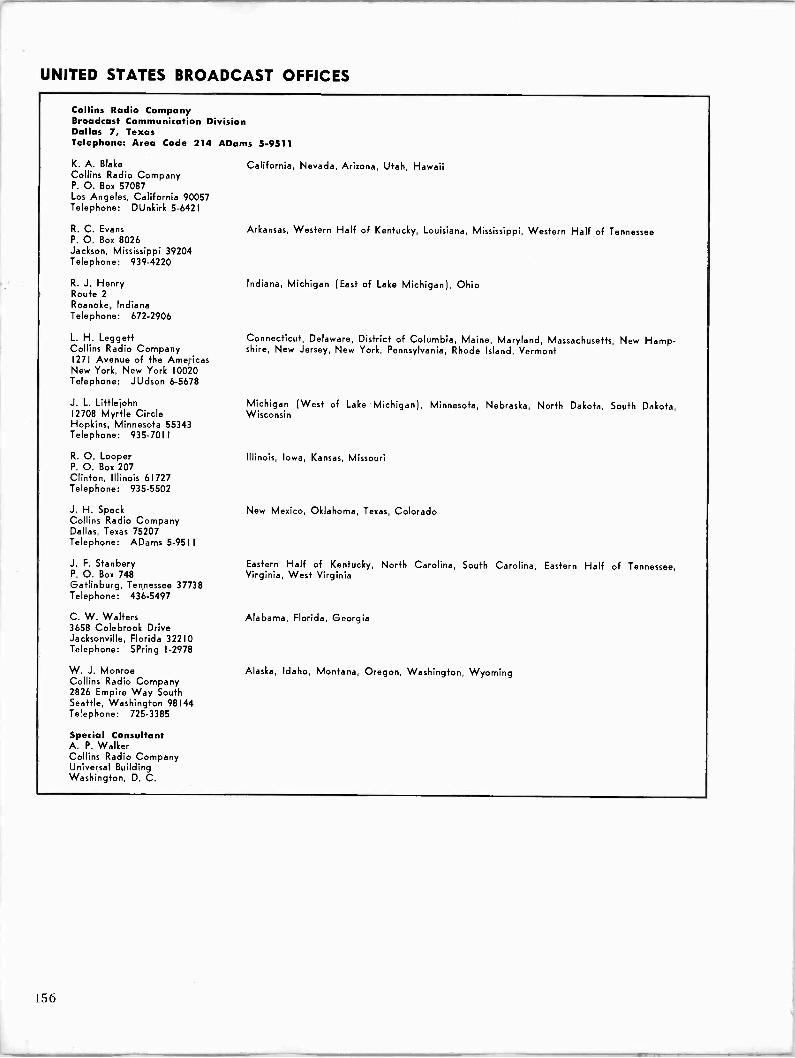
UNITED STATES BROADCAST OFFICES
Collins Radio Company Broadcast Communication Division Dallas 7, Texas Telephone: Area Code 214 ADams 5-9511
K. A. Blake Collins Radio Company P. O. Box 57087 Los Angeles, California 90057 Telephone: DUnkirk 5-6421
R. C. Evans P. O. Box 8026 Jackson, Mississippi 39204 Telephone: 939-4220
R. J. Henry Route 2
Roanoke, Indiana Telephone: 672-2906
L. H. Leggett Collins Radio Company 1271 Avenue of the Americas New York, New York 10020 Telephone: JUdson 6-5678
J. L. Littlejohn 12708 Myrtle Circle Hopkins, Minnesota 55343 Telephone: 935-7011
R. O. Looper P. O. Box 207 Clinton, Illinois 61727 Telephone: 935-5502
J. H. Speck Collins Radio Company Dallas, Texas 75207 Telephone: ADams 5-9511
J. F. Stanbery P. O. Box 748 Gatlinburg, Tennessee 37738 Telephone: 436-5497
C. W. Walters 3658 Colebrook Drive Jacksonville, Florida 32210 Telephone: SPring I-2978
W. J. Monroe Collins Radio Company 2826 Empire Way South Seattle, Washington 98144 Telephone: 725-3385
Special Consultant A. P. Walker Collins Radio Company Universal Building Washington, D. C.
California, Nevada, Arizona, Utah, Hawaii
Arkansas, Western Half of Kentucky, Louisiana, Mississippi, Western Half of Tennessee
Indiana, Michigan (East of Lake Michigan), Ohio
Connecticut, Delaware, District of Columbia, Maine, Maryland, Massachusetts, New Hamp- shire, New Jersey, New York, Pennsylvania, Rhode Island, Vermont
Michigan (West of Lake Michigan), Minnesota, Nebraska, North Dakota, South Dakota, Wisconsin
Illinois, Iowa, Kansas, Missouri
New Mexico, Oklahoma, Texas, Colorado
Eastern Half of Kentucky, North Carolina, South Carolina, Eastern Half of Tennessee, Virginia, West Virginia
Alabama, Florida, Georgia
Alaska, Idaho, Montana, Oregon, Washington, Wyoming
156

COLLINS
by is this trademark important to you a
For 30 years one principle has guided us in meeting our responsibility to provide
you with equipment of the highest performance standards. That principle is
integrity.
integrity in design 25% of our people are in Research and
Development.
integrity in manufacturing The best facilities, the best materials, the industry's finest craftsmen.
integrity in sales Honest claims, backed up by a seldom -
used but always dependable guarantee.
integrity in service Around the world, around the clock to
insure Collins performance.
Our trademark is a symbol of Collins integrity. You can depend on it.
COLLINS
COLLINS RADIO COMPANY Broadcast Communication Division, Dallas International Division, Dallas
157


(1,4 \\\ COLLINS
Related Documents