arXiv:cond-mat/9705080v1 [cond-mat.supr-con] 9 May 1997 Collective Oscillations in Superconducting Thin Films in the Presence of Vortices Mauro M. Doria a , Fl´avio M. R. d’Almeida b and O. Buisson c a Instituto de F´ ısica, Universidade Federal Fluminense, Campus da Praia Vermelha, Niter´ oi 24210-340 RJ, Brazil. b Departamento de F´ ısica, Pontif´ ıcia Universidade Cat´ olica do Rio de Janeiro, Rio de Janeiro 22452-970 RJ, Brazil. c Centre de Recherches sur les Tr` es Basses Temp´ eratures, Laboratoire Associ´ e` a l’Universit´ e Joseph Fourier, C.N.R.S., BP 166, 38042 Grenoble-C´ edex 9, France. Abstract A plasma wave propagates inside an anisotropic superconducting film sand- wiched between two semi-infinite non-conducting bounding dieletric media. Along the c-axis, perpendicular to the film surfaces, an external magnetic field is applied. We show how vortices, known to cause dissipation and change the penetration depth, affect the propagative mode. We obtain the complex wave number of this mode and, using Y BCO at 4 K as an example, determine a region where vortex contribution is dominant and dissipation is small. PACS 74.20.De 74.25.Nf 74.76.Bz 74.76.Db 1

Welcome message from author
This document is posted to help you gain knowledge. Please leave a comment to let me know what you think about it! Share it to your friends and learn new things together.
Transcript
arX
iv:c
ond-
mat
/970
5080
v1 [
cond
-mat
.sup
r-co
n] 9
May
199
7
Collective Oscillations in Superconducting Thin Films in the
Presence of Vortices
Mauro M. Doriaa, Flavio M. R. d’Almeidab and O. Buissonc
a Instituto de Fısica, Universidade Federal Fluminense, Campus da Praia Vermelha, Niteroi
24210-340 RJ, Brazil.
b Departamento de Fısica, Pontifıcia Universidade Catolica do Rio de Janeiro, Rio de Janeiro
22452-970 RJ, Brazil.
c Centre de Recherches sur les Tres Basses Temperatures, Laboratoire Associe a l’Universite
Joseph Fourier, C.N.R.S., BP 166, 38042 Grenoble-Cedex 9, France.
Abstract
A plasma wave propagates inside an anisotropic superconducting film sand-
wiched between two semi-infinite non-conducting bounding dieletric media.
Along the c-axis, perpendicular to the film surfaces, an external magnetic field
is applied. We show how vortices, known to cause dissipation and change the
penetration depth, affect the propagative mode. We obtain the complex wave
number of this mode and, using Y BCO at 4 K as an example, determine a
region where vortex contribution is dominant and dissipation is small.
PACS 74.20.De 74.25.Nf 74.76.Bz 74.76.Db
1
I. INTRODUCTION
In the plasma frequency, a collective oscillation of the electron gas in the positive ionic
background occurs, which is fundamental to understand the electromagnetic properties of
conductors. Below the plasma frequency the conductor reflects the incident electromagnetic
radiation and, above it becomes transparent thus allowing a propagative mode. For metals
the plasma frequency is typically found in the ultraviolet region (1015 − 1016 Hz)1.
A well-known feature of superconductors is the existence of a gap, the energy required
to break a Cooper pair in the ground state condensate. Typically the frequency associated
to the gap for conventional superconductors is in the 1011 Hz range, whereas for the new
high-Tc superconductors is one order magnitude higher2.
The question whether the superconductor can support collective modes without inducing
pair breaking effects is an old one and has been discussed since the early days of the theory
of superconductivity3,4. Apart from the so-called Carlson-Goldman mode, which happens
under special circumstances5,6, any other attempt to excite collective modes in isotropic bulk
superconductors leads to the destruction of the superconducting state. This follows the well-
known argument4 that the Coulomb interaction shifts the frequency of such oscillations, the
plasma frequency, to above the gap frequency. However, it was recently shown that highly
anisotropic superconductors do display a plasma oscillation below the superconducting gap7.
This oscillation, specially to the layered structure, is due to the Josephson coupling between
the superconducting planes.
Plasma modes in superconductors, isotropic or not, has been recently revisited from
another point of view. Plasma modes below the gap are possible without destroying the
superconducting state, as long as, they propagate in the interface between the supercon-
ductor and a non-conducting bounding medium of very high dieletric constant. This is the
so-called superficial plasma mode8,9, which is made possible by the charges located at the
interface of the superconductor and the dieletric medium, responsible for the creation of an
electric field concentrated mainly outside the superconductor.
2
In a thin film, the coupling between the two superficial plasma modes yields two possible
branches, a symmetric and a anti-symmetric, similarly to metals15–17 and semiconductors18.
The film thickness must be smaller than the London penetration depth in order to produce
this coupling. Oscillations between the kinetic energy of the superelectrons and the electrical
field energy take place in these modes and for this reason they are called plasma modes.
The lower frequency branch was predicted for superconductors10,12,11 some time ago and
observed in thin granular aluminium films, in the hundreds of MHz range13, and in thin
Y Ba2Cu3O7−x films14, in the higher frequency range of hundreds of GHz. The highest
frequency branch is predicted to be within experimental observation range for the high
Tc materials19. In case of highly anisotropic superconducting materials, measurements of
such upper and lower branches are expected to give information on the transverse and the
longitudinal London penetration depths, respectively19. In conclusion, plasma modes in
superconducting films can be an important tool for the probe of many intrinsic properties
of superconductors.
Long ago Gittleman and Rosenblum20 have studied the effects of an applied external
current at the radio and microwave frequency range into pinned vortices and obtained the
surface impedance. For an AC applied magnetic field and in the weak pinning regime,
Campbell21 showed that the effect of vortices can be described by a new AC London pen-
etration depth, whose square is the original London penetration depth squared plus a new
term describing the elastic interaction of vortices with the pinning centers. A few years ago
these models were generalized to convey the effects of creep22 and to provide a more detailed
description of the elastic properties of the vortex lattice near a surface23.
In this paper we study the effects of a constant uniform magnetic field, applied perpen-
dicularly to the thin film, into the thin film propagative mode. A sufficiently large magnetic
field allows the thermodynamic stability of a vortex system, which influences the collective
oscilations, affecting considerably the above modes. The vortices are induced into an oscil-
latory dissipative motion around their pinning centers. This motion couples to the electro-
magnetic fields resulting either into an underdamped or an overdamped regime. This paper
3
is developed in the context of independent vortex and superelectron degrees of freedom.
We understand by superelectron current, any supercurrent other than that one necessary to
bring the thermodynamic equilibrium of vortices. The vortex degree of freedom, described
by its position in space, also represents its intrinsic current. In this framework arises the
question whether the superelectron or the vortex contribution dominates the propagative
mode behavior. Hereafter, by plasma mode we refer to the limit where superelectron contri-
bution is the largest. So, pure plasma modes are found in the complete absence of an applied
magnetic field. In this paper we discuss conditions that render the modes underdamped and
vortex dominated. This is the case of interest because the attenuated oscillations can be
regarded as taking place between the vortex pinning energy and the electrical field energy.
The present work is done in the simplest possible theoretical framework, essentially a
generalization of the Gittleman-Rosenblum24,25, such that vortices and superelectrons are
independently coupled to Maxwell’s theory. Here we are mainly interested in the low tem-
perature regime and therefore, ignore the contribution of normal electrons to the problem.
Thus, wave damping is only due to the vortex dissipative motion.
We consider here an anisotropic superconductor with its uniaxial direction (c-axis) or-
thogonal to the film surfaces: the two London penetration depths, transverse (λ⊥) and
longitudinal (λ‖) to the surfaces give an anisotropy such that λ⊥/λ‖ > 1 . There are two
dielectric constants, the non-conducting medium and the superconductor ones, ε and εs, re-
spectively. Thus we are assigning to the superconductor a frequency independent dielectric
constant. We refer to the speed of light in the dielectric as v = c/√
ε. The uniform static
applied magnetic field is H0. For each individual vortex, the viscous drag coefficient is η0 and
the elastic restoring force constant (Labusch parameter) is α0. Their ratio, ω0 ≡ α0/η0, is
the so-called depinning frequency, above which dissipation becomes dominant in the vortex
motion. To have coupling between the two surfaces the film thickness, d, must be smaller
than λ‖.
The choice of a nonconducting bounding medium of very high dieletric constant is crucial
to lower the frequency range of the modes to below the gap frequency. For this reason we
4
take SrT iO3 as the bounding media, whose dieletric constant is known to be high up to the
GHz frequency13 at low temperatures: ε ≈ 2.0 104. Then the speed of light in the dielectric,
v = 2.1 106 ms−1, is substantially smaller than c. Our work is restricted to identical top
and bottom dielectric media, which does not imply lack of generality. Similar conclusions
should also apply to the general asymmetric case.
This paper is organized as follows. In the next section(II) we introduce the major equa-
tions describing the film mode in the presence of vortices. Its dispersion relation is analyt-
ically derived under some justifiable approximation. In section III we apply our model to
the high-Tc superconductor Y Ba2Cu3O7−δ, investigating a range of parameters such that
the lowest energy film mode is mostly associated to the vortex dynamics, but yet remains
underdamped. Finally, in section IV, we summarize our major results.
II. PROPAGATING MODES IN SUPERCONDUCTING FILMS WITH
PERPENDICULAR MAGNETIC FIELD
In this section we introduce the basic equations governing wave propagation in a su-
perconducting film sandwiched between two identical non-conducting dielectric media and
subjected to an uniform static magnetic field perpendicularly applied to the film surface.
An external electromagnetic wave of angular frequency ω and vacuum wavenumber k ≡ ω/c
is inserted in the dielectric bounded film. We determine the dispersion relation of the lowest
energy film mode, whose imaginary part reveals the attenuation behavior. Phenomenolog-
ical theories, such as the present one, only describe the superconductor in a energy range
much lower than the pair breaking threshold.
The electromagnetic dynamics of fields and superelectrons is described by the Maxwell’s
equations,
∇ · ~D = e (ns − ns) (1)
∇ · ~H = 0 (2)
5
∇× ~E = −µ0
∂ ~H
∂t(3)
∇× ~H = ~J +∂ ~D
∂t(4)
(5)
and consequently by the continuity equation,
∇ · ~J + e∂ns
∂t= 0 (6)
where ns represents the space and time dependent charge density, ns is its equilibrium
value and e stands for the electron charge. The distinction between ns and ns is necessary
because, propagation through the system disrupts the neutrality, as seen from Gauss’ law
(ns − ns = 0), and the local charge density is no longer constant.
As previously noticed the contribution of vortices and of superelectrons are indepen-
dent in the present model. The field ~J , the superelectron current density involved in net
macroscopic transport, and the field ~u, the vortex displacement from its equilibrium position
are independent in the present model. Hence the supercurrent density ~J corresponds to a
macroscopic average of the total superelectron motion, where the supercurrent necessary to
establish each vortex averages to zero. This approximation, valid for the present purposes,
cannot give any information on the supercurrent distribution surrounding each vortex line.
The simplest possible model that treats the response of the vortices to the presence of a
supercurrent external to them is the harmonic approximation of Gittleman and Rosenblum20,
η0
∂~u
∂t+ α0~u = Φ0( ~J × n) (7)
where n is a unit vector parallel to the flux lines mean direction. ¿From its turn, the dis-
placements of vortices from their equilibrium positions affect the propagating electromag-
netic wave. Fiory and Hebard24 have considered this question and found that besides the
kinetic inductance due to the superelectrons, the moving vortices also contribute, producing
an electric field inside the superconductor.
~E = µ0λ2 · ∂ ~J
∂t− µ0H0(
∂~u
∂t× n) (8)
6
The assumption of anisotropy yields a tensorial London penetration depth.
λ =
λ⊥ 0 0
0 λ‖ 0
0 0 λ‖
λ⊥ =
√
m⊥
µ0nse2λ‖ =
√
m‖
µ0nse2(9)
We pick a coordinate system where the two plane parallel surfaces separating the su-
perconducting film from the dielectric medium are at x = d/2 and x = −d/2, such that
n ≡ x and propagation is along the z axis. Vortex displacement is described by a vector field
parallel to the surfaces, ~u = uyy + uzz, with no orthogonal components to them (ux = 0).
According to symmetry arguments, all fields for the present geometry can be expressed as
Fi(x) exp [−ı(q z − ω t)], where the wave number q have yet to be determined. Because vor-
tex motion is dissipative, the wave’s amplitude decays exponentially with distance, and one
obtains for the fields’s expression Fi(x) exp (q′′ z) exp [−ı(q′ z − ω t)]. Then wave number
is a complex number, q = q′ + ıq′′.
Solving Maxwell’s equations for the chosen geometry gives two independent sets of field
components, the transverse electric (TE) and the transverse magnetic (TM) propagating
modes. In the former the non-zero electromagnetic field components are Hx, Ey and Hz, the
non-vanishing supercurrent is Jy and the vortex displacement is along the direction of wave
propagation (uz). This is an extremely high frequency mode in the present theory, and so
not interesting because it lies above the gap. For the latter, the non-zero electromagnetic
field components are Ex, Hy and Ez, the non-vanishing supercurrent components are Jx
and Jz and the propagating wave displaces the vortices perpendicularly to its direction
of propagation (uy). This is a very interesting mode because it supports low frequency
propagating waves. The major difference between TE and TM modes is that the latter
displays superficial charge densities at the film-dielectric interfaces and the former does not.
Such superficial charge densities stem from the supercurrent component orthogonal to the
film surface, Jx, which is discontinuous at the interfaces, thus rendering a strong coupling
between the superconducting film and the bounding media.
Introducing the time dependence exp (ı ω t) into Eq.(7) and Eq.(8) results in a change
7
of the penetration depth parallel to the surfaces due to the vortex contribution23,21.
ı ω µ0λ2
⊥ Jx = Ex, ı ω µ0λ2
‖ Jz = Ez (10)
λ2
‖ = λ2
‖ + (B0 Φ0
µ0 α0
)1
1 + ı(ω/ω0)(11)
This equation shows that vortices and superelectrons contribute additively to the parallel
penetration depth. Notice the depinning frequency ω0 establishes two distinct physical
regions for the vortices response. For ω ≪ ω0 dissipation is weak and λ‖ is essentially a
real number. For ω ≥ ω0 and a sufficiently large magnetic field, dissipation dominates the
vortices response because λ‖ is complex.
The superconductor’s dielectric constant is tensorial, ~D = ǫ0εs~E − ı ~J/ω = ǫ0ε · ~E and
for the TM mode we have that
εx = εs −1
(kλ⊥)2, εz = εs −
1
(kλ‖)2, k ≡ ω
c(12)
The TM field equations for the dielectric medium, (x ≥ d/2 and x ≤ −d/2), are given
bellow:
Ex = ıq
τ 2
∂Ez
∂x, Hy = ı ǫ0
ω ε
τ 2
∂Ez
∂x,
∂2Ez
∂x2− τ 2 Ez = 0, τ 2 = q2 − k2ε (13)
and the ones for the superconducting film (−d/2 ≤ x ≤ d/2) follow.
Ex = ıq εz
τ 2 εx
∂Ez
∂x, Hy = ı ǫ0
ω εz
τ 2
∂Ez
∂x,
∂2Ez
∂x2− τ 2 Ez = 0 τ 2 =
εz
εx
q2 − k2εz (14)
The dispersion relations follow from the continuity of the ratio Hy/Ez at a single interface,
say x = d/2, once assumed the longitudinal field Ez has a definite symmetry. It happens
in this way because, the superconductor film is bounded by the same dielectric medium in
both sides. Solving Eq.(13) one gets that above the film (x ≥ d/2),
Ez = Eo exp (−τ x) andHy
Ez
|x=d/2 = −ıωǫ0ε
τ(15)
¿From Eq.(14) we learn that for the superconducting film (−d/2 ≤ x ≤ d/2) there are two
possible states, symmetrical and anti-symmetrical, where the longitudinal field is expressed
8
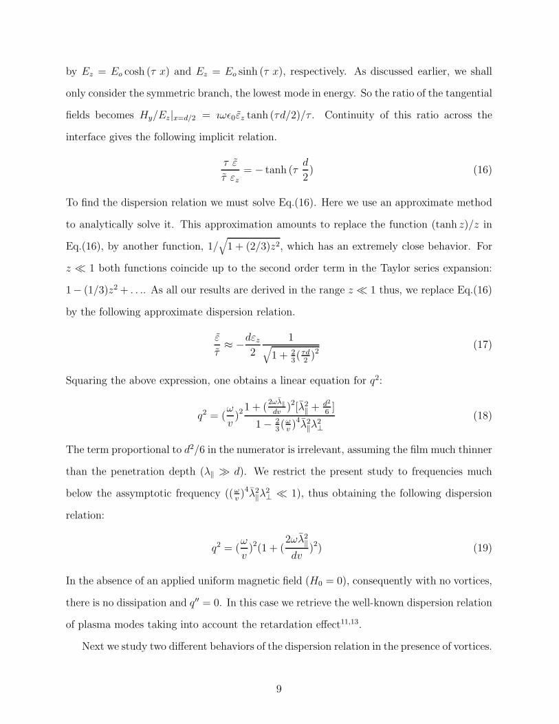
by Ez = Eo cosh (τ x) and Ez = Eo sinh (τ x), respectively. As discussed earlier, we shall
only consider the symmetric branch, the lowest mode in energy. So the ratio of the tangential
fields becomes Hy/Ez|x=d/2 = ıωǫ0εz tanh (τd/2)/τ . Continuity of this ratio across the
interface gives the following implicit relation.
τ ε
τ εz= − tanh (τ
d
2) (16)
To find the dispersion relation we must solve Eq.(16). Here we use an approximate method
to analytically solve it. This approximation amounts to replace the function (tanh z)/z in
Eq.(16), by another function, 1/√
1 + (2/3)z2, which has an extremely close behavior. For
z ≪ 1 both functions coincide up to the second order term in the Taylor series expansion:
1− (1/3)z2 + . . .. As all our results are derived in the range z ≪ 1 thus, we replace Eq.(16)
by the following approximate dispersion relation.
ε
τ≈ −dεz
2
1√
1 + 2
3( τd
2)2
(17)
Squaring the above expression, one obtains a linear equation for q2:
q2 = (ω
v)2
1 + (2ωλ‖dv
)2[λ2‖ + d2
6]
1 − 2
3(ω
v)4λ2
‖λ2⊥
(18)
The term proportional to d2/6 in the numerator is irrelevant, assuming the film much thinner
than the penetration depth (λ‖ ≫ d). We restrict the present study to frequencies much
below the assymptotic frequency ((ωv)4λ2
‖λ2⊥ ≪ 1), thus obtaining the following dispersion
relation:
q2 = (ω
v)2(1 + (
2ωλ2‖
dv)2) (19)
In the absence of an applied uniform magnetic field (H0 = 0), consequently with no vortices,
there is no dissipation and q′′ = 0. In this case we retrieve the well-known dispersion relation
of plasma modes taking into account the retardation effect11,13.
Next we study two different behaviors of the dispersion relation in the presence of vortices.
9
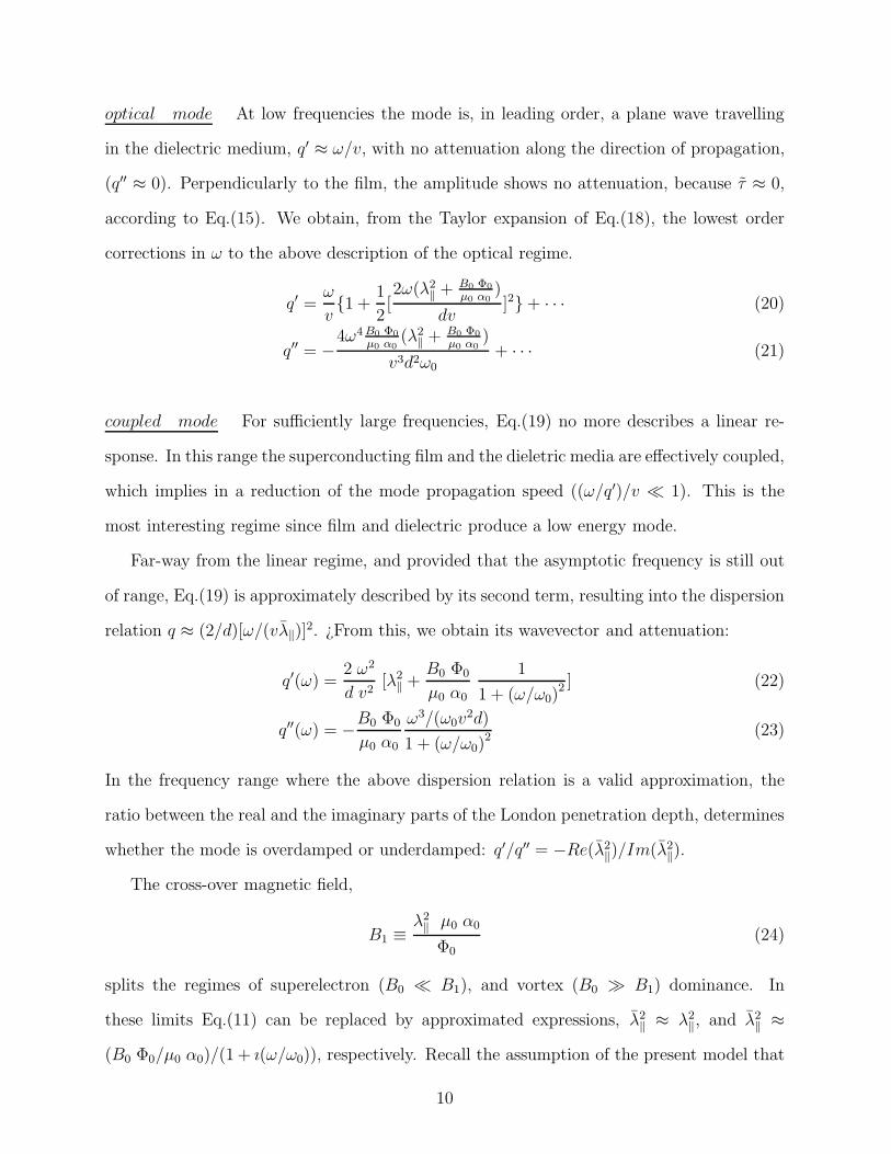
optical mode At low frequencies the mode is, in leading order, a plane wave travelling
in the dielectric medium, q′ ≈ ω/v, with no attenuation along the direction of propagation,
(q′′ ≈ 0). Perpendicularly to the film, the amplitude shows no attenuation, because τ ≈ 0,
according to Eq.(15). We obtain, from the Taylor expansion of Eq.(18), the lowest order
corrections in ω to the above description of the optical regime.
q′ =ω
v{1 +
1
2[2ω(λ2
‖ + B0 Φ0
µ0 α0
)
dv]2} + · · · (20)
q′′ = −4ω4 B0 Φ0
µ0 α0
(λ2‖ + B0 Φ0
µ0 α0
)
v3d2ω0
+ · · · (21)
coupled mode For sufficiently large frequencies, Eq.(19) no more describes a linear re-
sponse. In this range the superconducting film and the dieletric media are effectively coupled,
which implies in a reduction of the mode propagation speed ((ω/q′)/v ≪ 1). This is the
most interesting regime since film and dielectric produce a low energy mode.
Far-way from the linear regime, and provided that the asymptotic frequency is still out
of range, Eq.(19) is approximately described by its second term, resulting into the dispersion
relation q ≈ (2/d)[ω/(vλ‖)]2. ¿From this, we obtain its wavevector and attenuation:
q′(ω) =2 ω2
d v2[λ2
‖ +B0 Φ0
µ0 α0
1
1 + (ω/ω0)2] (22)
q′′(ω) = −B0 Φ0
µ0 α0
ω3/(ω0v2d)
1 + (ω/ω0)2
(23)
In the frequency range where the above dispersion relation is a valid approximation, the
ratio between the real and the imaginary parts of the London penetration depth, determines
whether the mode is overdamped or underdamped: q′/q′′ = −Re(λ2‖)/Im(λ2
‖).
The cross-over magnetic field,
B1 ≡λ2‖ µ0 α0
Φ0
(24)
splits the regimes of superelectron (B0 ≪ B1), and vortex (B0 ≫ B1) dominance. In
these limits Eq.(11) can be replaced by approximated expressions, λ2‖ ≈ λ2
‖, and λ2‖ ≈
(B0 Φ0/µ0 α0)/(1 + ı(ω/ω0)), respectively. Recall the assumption of the present model that
10
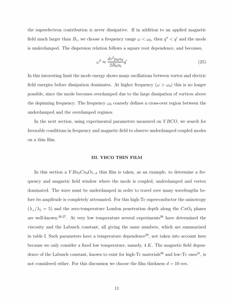
the superelectron contribution is never dissipative. If in addition to an applied magnetic
field much larger than B1, we choose a frequency range ω < ω0, then q′′ < q′ and the mode
is underdamped. The dispersion relation follows a square root dependence, and becomes,
ω2 ≈ dv2µ0α0
2B0φ0
q′ (25)
In this interesting limit the mode energy shows many oscillations between vortex and electric
field energies before dissipation dominates. At higher frequency (ω > ω0) this is no longer
possible, since the mode becomes overdamped due to the large dissipation of vortices above
the depinning frequency. The frequency ω0 coarsely defines a cross-over region between the
underdamped and the overdamped regimes.
In the next section, using experimental parameters measured on Y BCO, we search for
favorable conditions in frequency and magnetic field to observe underdamped coupled modes
on a thin film.
III. YBCO THIN FILM
In this section a Y Ba2Cu3O7−δ thin film is taken, as an example, to determine a fre-
quency and magnetic field window where the mode is coupled, underdamped and vortex
dominated. The wave must be underdamped in order to travel over many wavelengths be-
fore its amplitude is completely attenuated. For this high-Tc superconductor the anisotropy
(λ⊥/λ‖ = 5) and the zero-temperature London penetration depth along the CuO2 planes
are well-known.26,27. At very low temperature several experiments28 have determined the
viscosity and the Labusch constant, all giving the same numbers, which are summarized
in table I. Such parameters have a temperature dependence29, not taken into account here
because we only consider a fixed low temperature, namely, 4 K. The magnetic field depen-
dence of the Labusch constant, known to exist for high-Tc materials30 and low-Tc ones31, is
not considered either. For this discussion we choose the film thickness d = 10 nm.
11
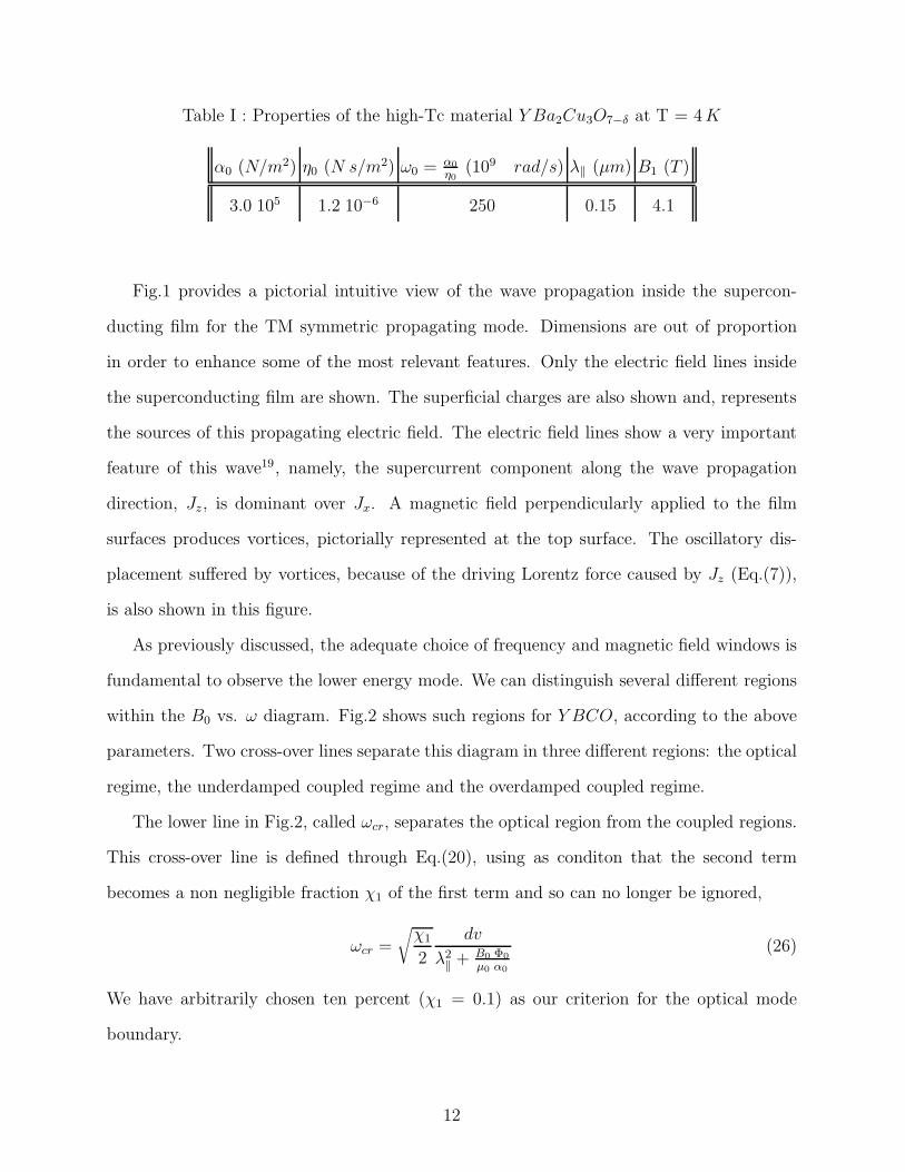
Table I : Properties of the high-Tc material Y Ba2Cu3O7−δ at T = 4 K
α0 (N/m2) η0 (N s/m2) ω0 = α0
η0
(109 rad/s) λ‖ (µm) B1 (T )
3.0 105 1.2 10−6 250 0.15 4.1
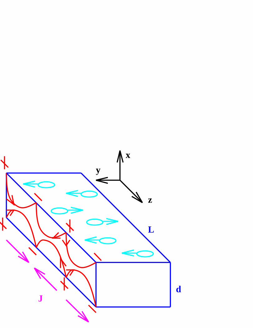
Fig.1 provides a pictorial intuitive view of the wave propagation inside the supercon-
ducting film for the TM symmetric propagating mode. Dimensions are out of proportion
in order to enhance some of the most relevant features. Only the electric field lines inside
the superconducting film are shown. The superficial charges are also shown and, represents
the sources of this propagating electric field. The electric field lines show a very important
feature of this wave19, namely, the supercurrent component along the wave propagation
direction, Jz, is dominant over Jx. A magnetic field perpendicularly applied to the film
surfaces produces vortices, pictorially represented at the top surface. The oscillatory dis-
placement suffered by vortices, because of the driving Lorentz force caused by Jz (Eq.(7)),
is also shown in this figure.
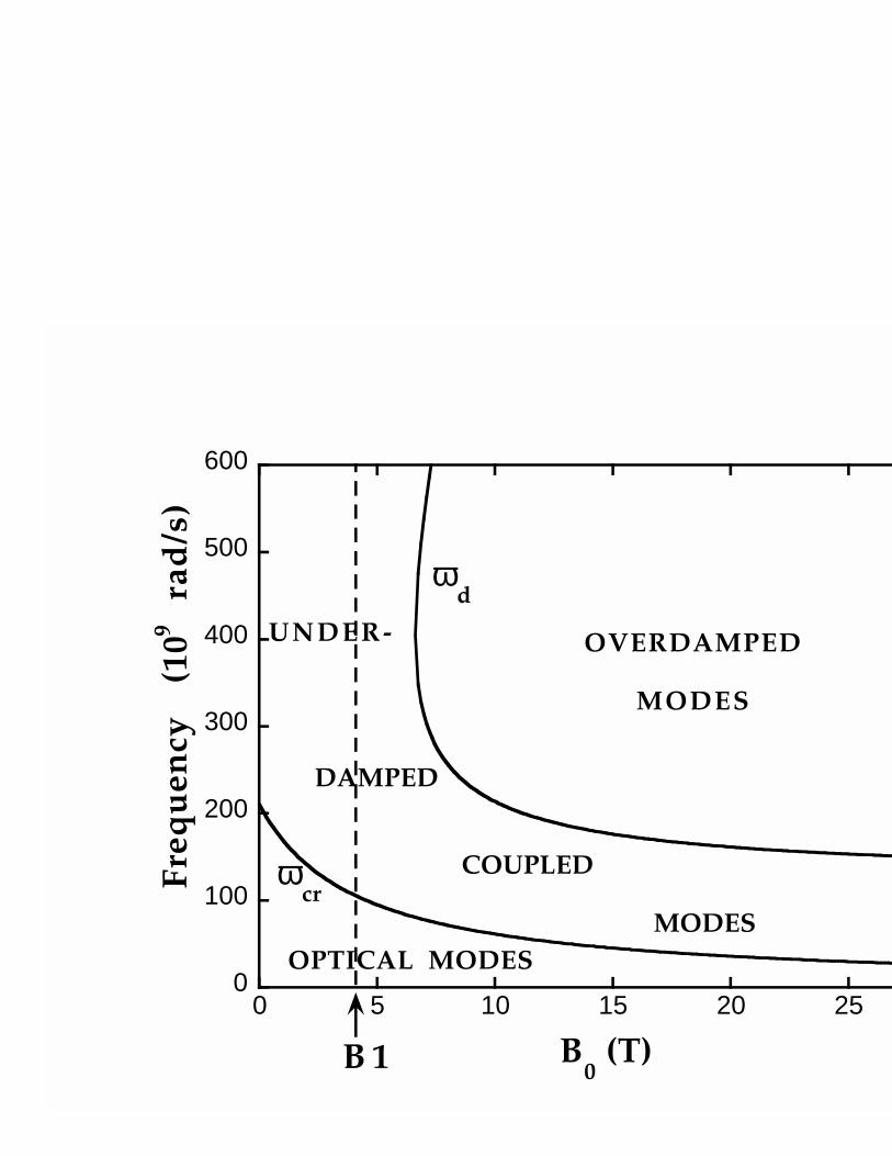
As previously discussed, the adequate choice of frequency and magnetic field windows is
fundamental to observe the lower energy mode. We can distinguish several different regions
within the B0 vs. ω diagram. Fig.2 shows such regions for Y BCO, according to the above
parameters. Two cross-over lines separate this diagram in three different regions: the optical
regime, the underdamped coupled regime and the overdamped coupled regime.
The lower line in Fig.2, called ωcr, separates the optical region from the coupled regions.
This cross-over line is defined through Eq.(20), using as conditon that the second term
becomes a non negligible fraction χ1 of the first term and so can no longer be ignored,
ωcr =
√
χ1
2
dv
λ2‖ + B0 Φ0
µ0 α0
(26)
We have arbitrarily chosen ten percent (χ1 = 0.1) as our criterion for the optical mode
boundary.
12
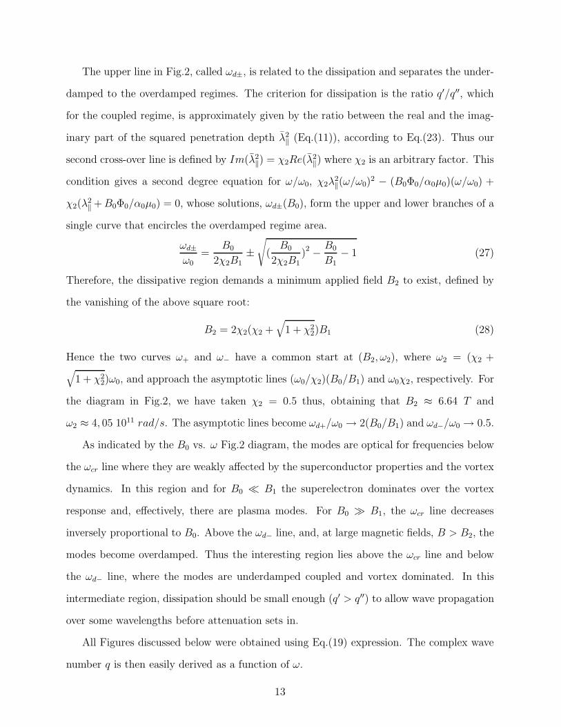
The upper line in Fig.2, called ωd±, is related to the dissipation and separates the under-
damped to the overdamped regimes. The criterion for dissipation is the ratio q′/q′′, which
for the coupled regime, is approximately given by the ratio between the real and the imag-
inary part of the squared penetration depth λ2‖ (Eq.(11)), according to Eq.(23). Thus our
second cross-over line is defined by Im(λ2‖) = χ2Re(λ2
‖) where χ2 is an arbitrary factor. This
condition gives a second degree equation for ω/ω0, χ2λ2‖(ω/ω0)
2 − (B0Φ0/α0µ0)(ω/ω0) +
χ2(λ2‖ + B0Φ0/α0µ0) = 0, whose solutions, ωd±(B0), form the upper and lower branches of a
single curve that encircles the overdamped regime area.
ωd±
ω0
=B0
2χ2B1
±√
(B0
2χ2B1
)2 − B0
B1
− 1 (27)
Therefore, the dissipative region demands a minimum applied field B2 to exist, defined by
the vanishing of the above square root:
B2 = 2χ2(χ2 +√
1 + χ22)B1 (28)
Hence the two curves ω+ and ω− have a common start at (B2, ω2), where ω2 = (χ2 +√
1 + χ22)ω0, and approach the asymptotic lines (ω0/χ2)(B0/B1) and ω0χ2, respectively. For
the diagram in Fig.2, we have taken χ2 = 0.5 thus, obtaining that B2 ≈ 6.64 T and
ω2 ≈ 4, 05 1011 rad/s. The asymptotic lines become ωd+/ω0 → 2(B0/B1) and ωd−/ω0 → 0.5.
As indicated by the B0 vs. ω Fig.2 diagram, the modes are optical for frequencies below
the ωcr line where they are weakly affected by the superconductor properties and the vortex
dynamics. In this region and for B0 ≪ B1 the superelectron dominates over the vortex
response and, effectively, there are plasma modes. For B0 ≫ B1, the ωcr line decreases
inversely proportional to B0. Above the ωd− line, and, at large magnetic fields, B > B2, the
modes become overdamped. Thus the interesting region lies above the ωcr line and below
the ωd− line, where the modes are underdamped coupled and vortex dominated. In this
intermediate region, dissipation should be small enough (q′ > q′′) to allow wave propagation
over some wavelengths before attenuation sets in.
All Figures discussed below were obtained using Eq.(19) expression. The complex wave
number q is then easily derived as a function of ω.
13
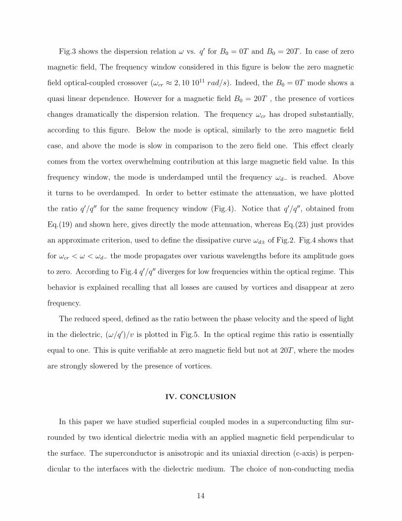
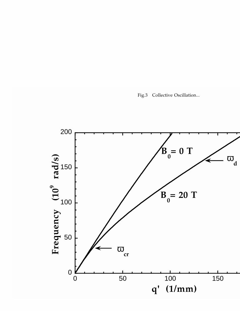
Fig.3 shows the dispersion relation ω vs. q′ for B0 = 0T and B0 = 20T . In case of zero
magnetic field, The frequency window considered in this figure is below the zero magnetic
field optical-coupled crossover (ωcr ≈ 2, 10 1011 rad/s). Indeed, the B0 = 0T mode shows a
quasi linear dependence. However for a magnetic field B0 = 20T , the presence of vortices
changes dramatically the dispersion relation. The frequency ωcr has droped substantially,
according to this figure. Below the mode is optical, similarly to the zero magnetic field
case, and above the mode is slow in comparison to the zero field one. This effect clearly
comes from the vortex overwhelming contribution at this large magnetic field value. In this
frequency window, the mode is underdamped until the frequency ωd− is reached. Above
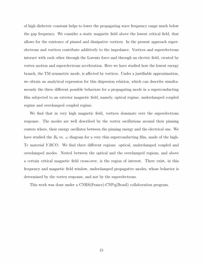
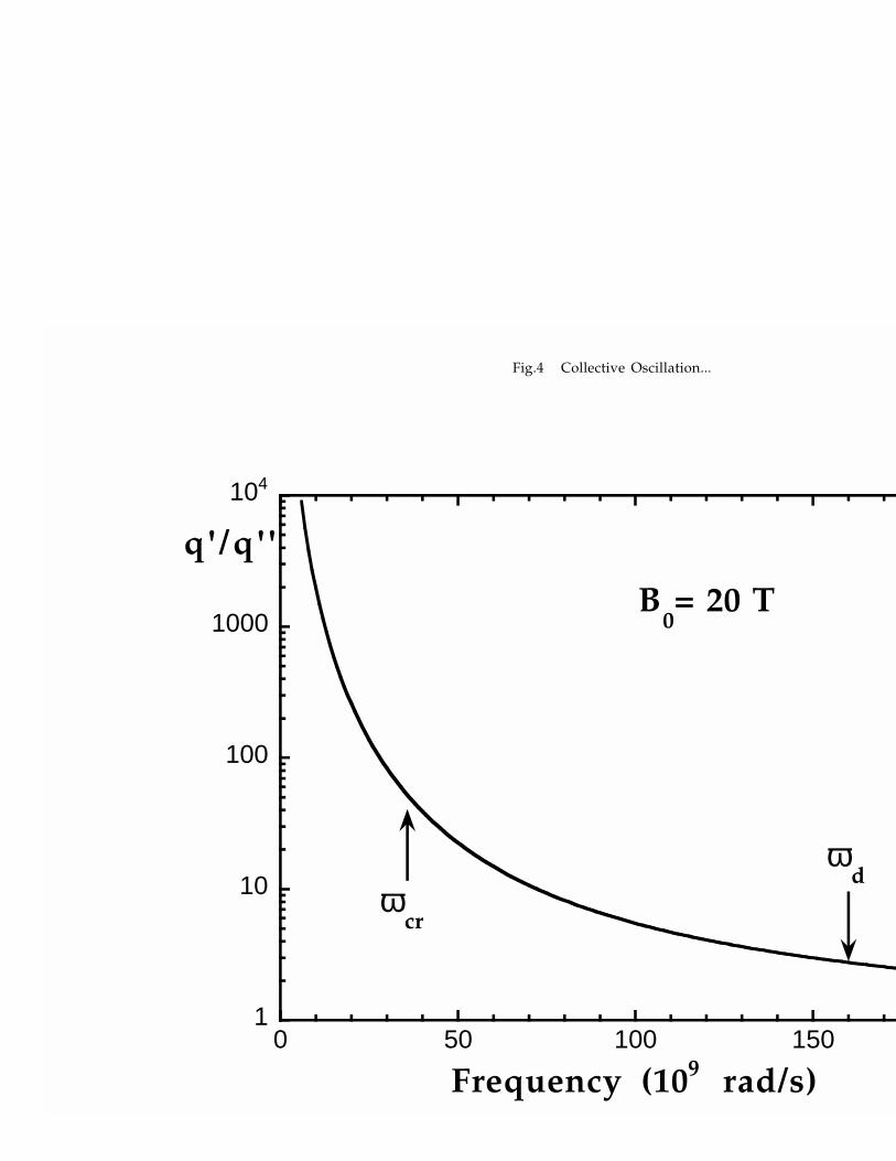
it turns to be overdamped. In order to better estimate the attenuation, we have plotted
the ratio q′/q′′ for the same frequency window (Fig.4). Notice that q′/q′′, obtained from
Eq.(19) and shown here, gives directly the mode attenuation, whereas Eq.(23) just provides
an approximate criterion, used to define the dissipative curve ωd± of Fig.2. Fig.4 shows that
for ωcr < ω < ωd− the mode propagates over various wavelengths before its amplitude goes
to zero. According to Fig.4 q′/q′′ diverges for low frequencies within the optical regime. This
behavior is explained recalling that all losses are caused by vortices and disappear at zero
frequency.
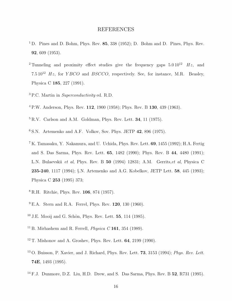
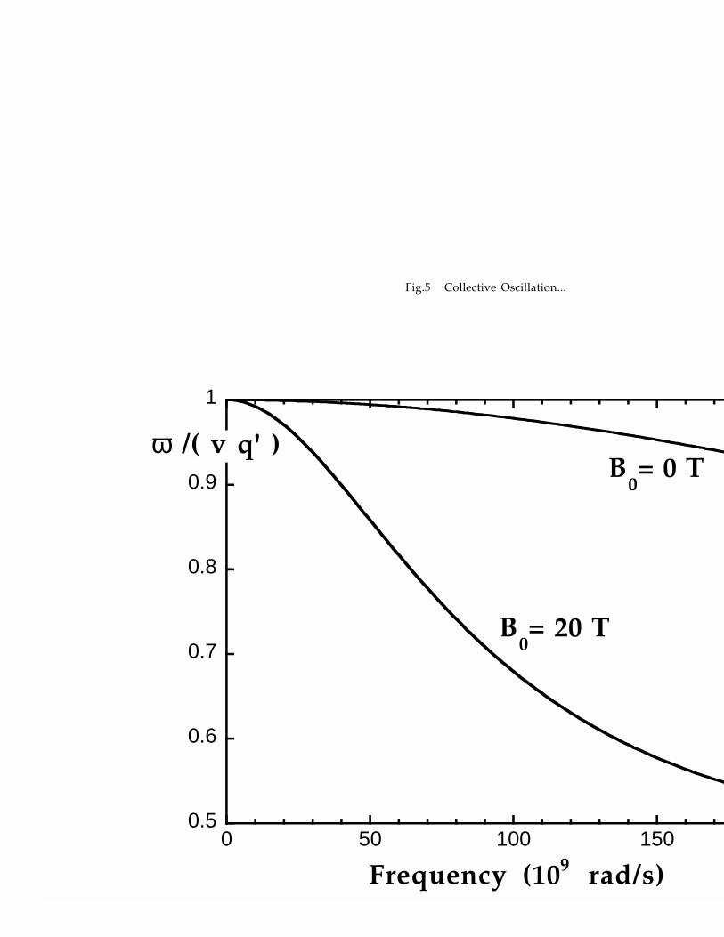
The reduced speed, defined as the ratio between the phase velocity and the speed of light
in the dielectric, (ω/q′)/v is plotted in Fig.5. In the optical regime this ratio is essentially
equal to one. This is quite verifiable at zero magnetic field but not at 20T , where the modes
are strongly slowered by the presence of vortices.
IV. CONCLUSION
In this paper we have studied superficial coupled modes in a superconducting film sur-
rounded by two identical dielectric media with an applied magnetic field perpendicular to
the surface. The superconductor is anisotropic and its uniaxial direction (c-axis) is perpen-
dicular to the interfaces with the dielectric medium. The choice of non-conducting media
14
of high dielectric constant helps to lower the propagating wave frequency range much below
the gap frequency. We consider a static magnetic field above the lowest critical field, that
allows for the existence of pinned and dissipative vortices. In the present approach super-
electrons and vortices contribute additively to the impedance. Vortices and superelectrons
interact with each other through the Lorentz force and through an electric field, created by
vortex motion and superelectrons acceleration. Here we have studied how the lowest energy
branch, the TM symmetric mode, is affected by vortices. Under a justifiable approximation,
we obtain an analytical expression for this dispersion relation, which can describe simulta-
neously the three different possible behaviors for a propagating mode in a superconducting
film subjected to an exterior magnetic field, namely, optical regime, underdamped coupled
regime and overdamped coupled regime.
We find that in very high magnetic field, vortices dominate over the superelectrons
response. The modes are well described by the vortex oscillations around their pinning
centers where, their energy oscillates between the pinning energy and the electrical one. We
have studied the B0 vs. ω diagram for a very thin superconducting film, made of the high-
Tc material Y BCO. We find three different regions: optical, underdamped coupled and
overdamped modes. Nested between the optical and the overdamped regions, and above
a certain critical magnetic field cross-over, is the region of interest. There exist, in this
frequency and magnetic field window, underdamped propagative modes, whose behavior is
determined by the vortex response, and not by the superelectrons.
This work was done under a CNRS(France)-CNPq(Brasil) collaboration program.
15
REFERENCES
1 D. Pines and D. Bohm, Phys. Rev. 85, 338 (1952); D. Bohm and D. Pines, Phys. Rev.
92, 609 (1953).
2 Tunneling and proximity effect studies give the frequency gaps 5.0 1012 Hz, and
7.5 1012 Hz, for Y BCO and BSCCO, respectively. See, for instance, M.R. Beasley,
Physica C 185, 227 (1991).
3 P.C. Martin in Superconductivity ed. R.D.
4 P.W. Anderson, Phys. Rev. 112, 1900 (1958); Phys. Rev. B 130, 439 (1963).
5 R.V. Carlson and A.M. Goldman, Phys. Rev. Lett. 34, 11 (1975).
6 S.N. Artemenko and A.F. Volkov, Sov. Phys. JETP 42, 896 (1975).
7 K. Tamasaku, Y. Nakamura, and U. Uchida, Phys. Rev. Lett. 69, 1455 (1992); H.A. Fertig
and S. Das Sarma, Phys. Rev. Lett. 65, 1482 (1990); Phys. Rev. B 44, 4480 (1991);
L.N. Bulaevskii et al, Phys. Rev. B 50 (1994) 12831; A.M. Gerrits,et al, Physica C
235-240, 1117 (1994); §.N. Artemenko and A.G. Kobelkov, JETP Lett. 58, 445 (1993);
Physica C 253 (1995) 373;
8 R.H. Ritchie, Phys. Rev. 106, 874 (1957).
9 E.A. Stern and R.A. Ferrel, Phys. Rev. 120, 130 (1960).
10 J.E. Mooij and G. Schon, Phys. Rev. Lett. 55, 114 (1985).
11 B. Mirhashem and R. Ferrell, Physica C 161, 354 (1989).
12 T. Mishonov and A. Groshev, Phys. Rev. Lett. 64, 2199 (1990).
13 O. Buisson, P. Xavier, and J. Richard, Phys. Rev. Lett. 73, 3153 (1994); Phys. Rev. Lett.
74E, 1493 (1995).
14 F.J. Dunmore, D.Z. Liu, H.D. Drew, and S. Das Sarma, Phys. Rev. B 52, R731 (1995).
16
15 H. Boersch, J. Geiger, A. Imbush, and N. Niedrig, Phys. Lett. 22, 146 (1966).
16 M. Fukui, V.C.Y. So, and R. Normandin, Phys. Stat. Sol. 91, K61 (1979).
17 D. Sarid, Phys. Rev. Lett. 47, 1927 (1981).
18 S. Ushioda and R. Loudon, in Surface Polaritons, edited by V.M. Agranovich and A.A.
Maradudin (North-Holland P.Co., New York, 1982), p.573.
19 M.M. Doria, F. Parage, and O. Buisson, Europhys. Lett. 35, 445 (1996).
20 J.I. Gittleman and B. Rosenblum, Phys. Rev. 39, 2617 (1968).
21 A.M. Campbell , J. Phys. C 2, 1492 (1969); 4, 3186 (1971).
22 M.W. Coffey and J.R. Clem , Phys. Rev. Lett. 67, 386 (1991).
23 E.H. Brandt, Phys. Rev. Lett. 67, 2219 (1991).
24 A.T. Fiory and A.F. Hebard, Phys. Rev. B 25, 2073 (1982).
25 A.E. Koshelev and V.M. Vinokur, Physica C 173, 465 (1991).
26 G. Blatter et al., Rev. Mod. Phys. 66, 1125 (1994).
27 E.H. Brandt, Rep. Prog. Phys. 58, 1465 (1995).
28 M. Golosovsky, M. Tsindlekht, and D. Davidov, Supercond. Sci Technol. 9, 1 (1996).
29 D.H. Wu, J.C. Booth and S.M. Anlage, Phys. Rev. Lett. 75, 525 (1995).
30 T. Hanaguri et al., Physica C 235-240, 1991 (1994).
31 J. Kober et al., Phys. Rev. Lett. 66, 2507 (1990).
17
FIGURES
FIG. 1. A pictorial view of wave propagation in a superconducting film surrounded by identical
non-conducting media in both sides. Scales are out of proportion in order to enhance some of the
features. The instantaneous electric field is shown here only inside the film. The superficial charge
densities and the motion of the vortex lines are also sketched here.
FIG. 2. The diagram B vs. ω for a very thin Y BCO superconducting film, d = 10nm-thick,
surrounded by the dielectric material SrT iO3 shows three regions: optical, underdamped coupled
and overdamped modes. The dashed line separates the superelectron (below) to the vortex (above)
dominated regime.
FIG. 3. Dispersion relation ω versus q′ for a 10 nm Y BCO film. In this frequency range and
for zero magnetic field the dispersion relation is purely optical. For B0 = 20 T , the modes are
associated to the vortex dynamic and are underdamped until the frequency ωd is reached.
FIG. 4. The ratio q′/q′′ is displayed here versus ω showing the mode damping for the same
frequency range of Fig.3. The ratio, although undergoes a dramatic change in this range, is always
larger than one, thus signaling underdamped behavior.
FIG. 5. The retardation ratio, (ω/q′)/v, is shown for the frequency range of Fig.4. For
zero applied field this ratio is near one showing that mode is essentially optical. This is not case
for B0 = 20 T whose strong deviation from one signals coupling between the dielectric and the
superconducting film due to the presence of vortices.
18
dJ
x
y
L
z
0
100
200
300
400
500
600
0 5 10 15 20 25
Fre
qu
en
cy
(109
ra
d/s
)
B0 (T)B 1
OVERDAMPED
MODES
OPTICAL MODES
UNDER-
DAMPED
COUPLED
MODES
ωcr
ωd

0
50
100
150
200
0 50 100 150
Fre
qu
en
cy
(10
9
rad
/s)
q' (1/mm)
B0= 20 T
B0= 0 T
ωcr
ωd
Fig.3 Collective Oscillation...
1
10
100
1000
104
0 50 100 150
q'/q' '
Frequency (109 rad/s)
B0= 20 T
ωcr
ωd
Fig.4 Collective Oscillation...
0.5
0.6
0.7
0.8
0.9
1
0 50 100 150
ω /( v q' )
Frequency (109 rad/s)
B0= 20 T
B0= 0 T
Fig.5 Collective Oscillation...
Related Documents


