Collective effects, University of Oslo, Erik Adli, University of Oslo, August 2014, [email protected], [email protected].
Dec 16, 2015
Welcome message from author
This document is posted to help you gain knowledge. Please leave a comment to let me know what you think about it! Share it to your friends and learn new things together.
Transcript

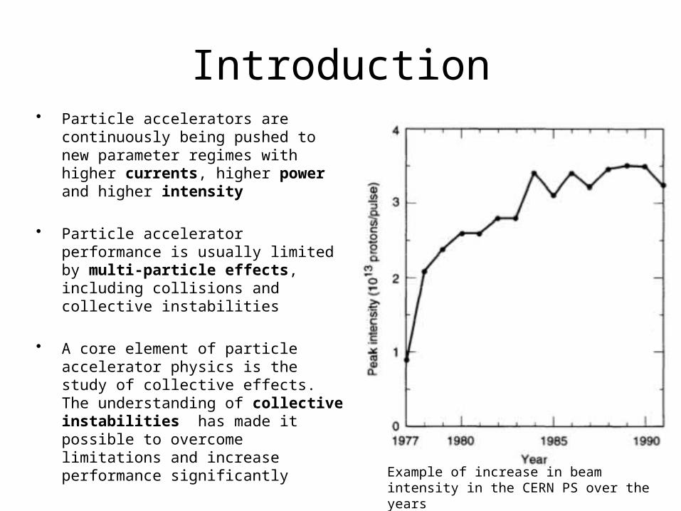
Introduction• Particle accelerators are continuously
being pushed to new parameter regimes with higher currents, higher power and higher intensity
• Particle accelerator performance is usually limited by multi-particle effects, including collisions and collective instabilities
• A core element of particle accelerator physics is the study of collective effects. The understanding of collective instabilities has made it possible to overcome limitations and increase performance significantly
• We here describe the two most common effects, space charge and wake fields, in some detail.
Example of increase in beam intensity in the CERN PS over the years
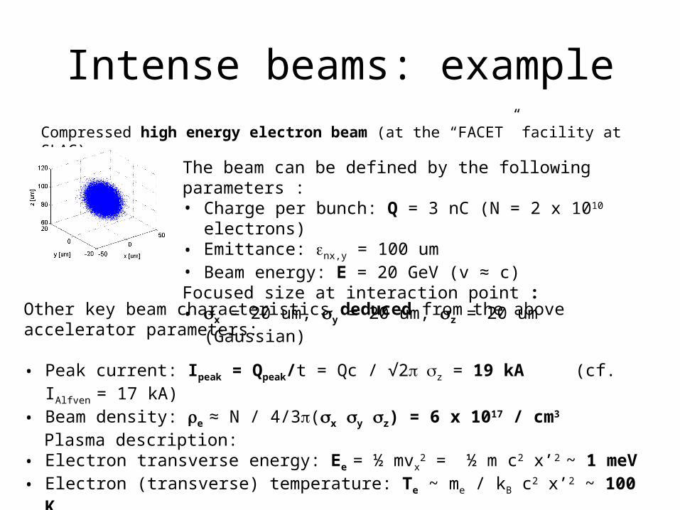
Compressed high energy electron beam (at the “FACET” facility at SLAC) :
Intense beams: example
The beam can be defined by the following parameters :• Charge per bunch: Q = 3 nC (N = 2 x 10¹⁰ electrons)• Emittance: enx,y = 100 um• Beam energy: E = 20 GeV (v ≈ c)Focused size at interaction point :• sx = 20 um, sy = 20 um, sz = 20 um (Gaussian)
Other key beam characteristics deduced from the above accelerator parameters:
• Peak current: Ipeak = Qpeak/t = Qc / √2 p sz = 19 kA (cf. IAlfven = 17 kA)• Beam density: re ≈ N / 4/3p(sx sy sz) = 6 x 10¹⁷ / cm3
Plasma description: • Electron transverse energy: Ee = ½ mvx
2 = ½ m c2 x’2 ~ 1 meV • Electron (transverse) temperature: Te ~ me / kB c2 x’2 ~ 100 K• Debye length (shielding length): lD = √(e0kBT/e2n0) ~ 1 nm
-> lD << sx, sy, sz (collective effects dominate over collisional effects)

Space charge – field view point
s
Fields transforms to the lab frame as :
We observe beams, fields and forces in the lab frame. The force on particle 1 is F = e(E+v1 x B). Particle 2 generates no magnetic field in its rest frame, which gives the relation (BT – v2/c2 x E) = 0. The total transverse force on particle 1 in the lab frame is thus F = e(E - v1 x (v2/c2 x E)), or for parallel velocities :
For v1 = v2 = v we get relativistic space charge surpression :
Fx,y = eEx,y (1±v1v2/c2)
x’
y'
z
v2
x
y
z
v1
Two-particle interaction :
Fx,y = eEx,y (1-v2/c2) = eEx,y / g2
xlab

EM fields from a relativistic particle
v=0
Fields in particle’s rest frame Fields in lab frame
Ultra-relativistic limit (v=c) :
Lorentz Tranformations
Field compression-> “Pancake field”

Space Charge – lab frame
Alternate calculations: Gauss law's. Gauss law is valid also for relativistic moving (or accelerating) charges. In the rest frame, the beam sees an electrostatic field. In the lab frame, the moving charges produce a magnetic field.
We assume a uniform density beam in shape of a cylinder, with beam charge density r = Ne / pa2L :
Gauss law gives :
Ampere’s law gives :
Combine terms Fr = e(Er - vBf) :
+
+
F
F
+
+
FE
FE
vFB
FB
+
+
c
c
rEr02
rc
vB
202
Rest frame Lab frame
Lab frame, v = cThis is the direct space charge effect. “Direct” : does not take into account the effects of conducting walls surrounding the beam.

• Typical lattice focusing (FODO with ~10 m between magnets): <b> ~ 10 m -> Kb = 1/100 m-2 • For our example 20 GeV electron beam (a few slides ago) : KSC = 5 x 10⁻⁵ m-2 << Kb
-> space charge completely suppressed at high Lortentz factor• For a 20 MeV electron beam a few slides ago : KSC = 5 x 10⁴ m-2 >> Kb
KSC ~ Ipeak / (bg)3 “beam perveance”
Space Charge for Guassian Beams

K. Schindl
Summary
Linear defocusing. Gives tune shift in rings. Can be compensated by
stronger lattice.
Non-linear defocusing. Gives tune shift and tune spread in rings.

Beam-beam effectsRelativistic space charge supression is only for equal charge moving at the same velocity, in the same direction (and then only holds fully in free space). These requirement are often violated. An important example is the Beam-Beam interaction :
• Two colliding beams see the field of each other before collision. They may be strongly attracted, and may deform.
• Important limitation for collider luminosity. Considered the main challenge for LHC luminosity. We will revisit the topic of beam beam effects in the linear collider lectures.
Fx,y = eEx,y (1+v1v2/c2)For v1 and v2 of opposite sign in our previous calculation (5 slides ago) we get :
Wake fields
Most of the material is G. Rumolo’s slides from CAS Course on wake fields

11
Wake fields (general)
z z2b z
Source, q1
Witness, q2
– While source and witness ( qi d(s-ct) ), distant by z<0, move centered in a perfectly conducting chamber, the witness does not feel any force (g >> 1)
– When the source encounters a discontinuity (e.g., transition, device), it produces an electromagnetic field, which trails behind (wake field)o The source loses energyo The witness feels a net force all along an effective length of the structure, L
L

Wake field characteristics
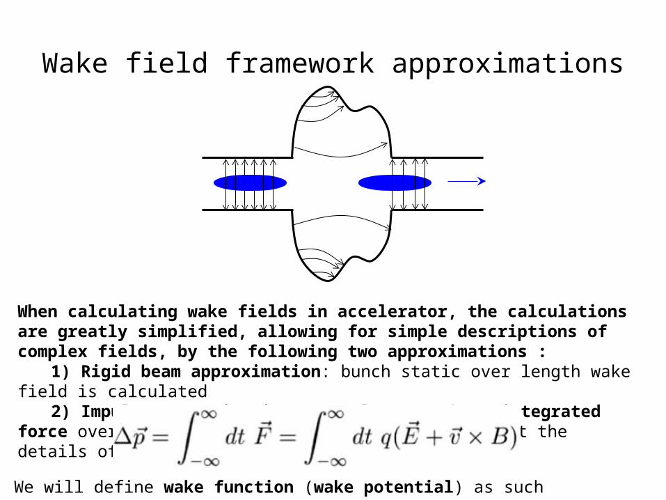
Wake field framework approximations
When calculating wake fields in accelerator, the calculations are greatly simplified, allowing for simple descriptions of complex fields, by the following two approximations :
1) Rigid beam approximation: bunch static over length wake field is calculated2) Impulse approximation: we only care about integrated force over the length
wake field is calculated, not the details of the fields in time and space
We will define wake function (wake potential) as such integrated quantities.

14
Wake fields (general)
2b
Source, q1
Witness, q2
L
– Not only geometric discontinuities cause electromagnetic fields trailing behind sources traveling at light speed.
– For example, a pipe with finite conductivity causes a delay in the induced currents, which also produces delayed electromagnetic fieldso No ringing, only slow decayo The witness feels a net force all along an effective length of the structure, L
– In general, also electromagnetic boundary conditions can be the origin of wake fields.
z

z
1. The longitudinal plane
dp/p0

16
Longitudinal wake function: definition
2b z
Source, q1
Witness, q2
L

17
Longitudinal wake function: properties
– The value of the wake function in 0, W||(0), is related to the energy lost by the source particle in the creation of the wake
– W||(0)>0 since DE1<0
– W||(z) is discontinuous in z=0 and it vanishes for all z>0 because of the ultra-relativistic approximation
W||(z)
z
18
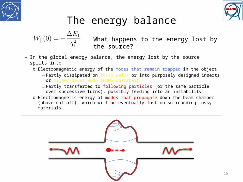
The energy balance
– In the global energy balance, the energy lost by the source splits into o Electromagnetic energy of the modes that remain trapped in the object
⇒ Partly dissipated on lossy walls or into purposely designed inserts or higher-order mode (HOM) absorbers
⇒ Partly transferred to following particles (or the same particle over successive turns), possibly feeding into an instability
o Electromagnetic energy of modes that propagate down the beam chamber (above cut-off), which will be eventually lost on surrounding lossy materials
What happens to the energy lost by the source?

19
The energy balance
– In the global energy balance, the energy lost by the source splits into o Electromagnetic energy of the modes that remain trapped in the object
⇒ Partly dissipated on lossy walls or into purposely designed inserts or HOM absorbers
⇒ Partly transferred to following particles (or the same particle over successive turns), possibly feeding into an instability!
o Electromagnetic energy of modes that propagate down the beam chamber (above cut-off), which will be eventually lost on surrounding lossy materials
What happens to the energy lost by the source?
The energy loss is very important because
⇒ It causes beam induced heating of the beam environment (damage, outgassing)
⇒ It feeds into both longitudinal and transverse instabilities through the associated EM fields

20
Longitudinal impedance
– The wake function of an accelerator component is basically its Green function in time domain (i.e., its response to a pulse excitation)
⇒ Very useful for macroparticle models and simulations, because it can be used to describe the driving terms in the single particle equations of motion!
– We can also describe it as a transfer function in frequency domain– This is the definition of longitudinal beam coupling impedance of the element
under study
[W] [ /Ws]

21
Longitudinal impedance: resonator
W||Re[Z||]
Im[Z||]
T=2p/wr
wr
– The frequency wr is related to the oscillation of Ez, and therefore to the frequency of the mode excited in the object
– The decay time depends on how quickly the stored energy is dissipated (quantified by a quality factor Q)

22
Longitudinal impedance: cavity
– A more complex example: a simple pill-box cavity with walls having finite conductivity
– Several modes can be excited– Below the pipe cut-off frequency the width
of the peaks is only determined by the finite conductivity of the walls
– Above, losses also come from propagation in the chamber
Re[Z||]
Im[Z||]

23
Single bunch effects
W||
Re[Z||]Im[Z||]

24
Single bunch effects
W||
25
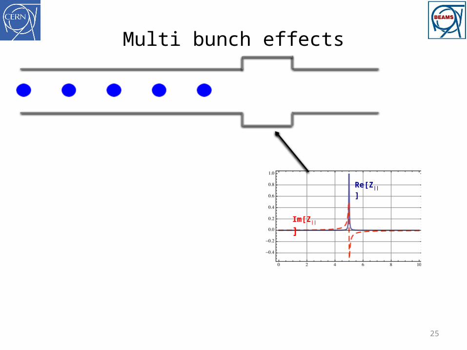
Multi bunch effects
Re[Z||]
Im[Z||]
26
Multi bunch effects
W||

27
Multi bunch effects
Dz
28
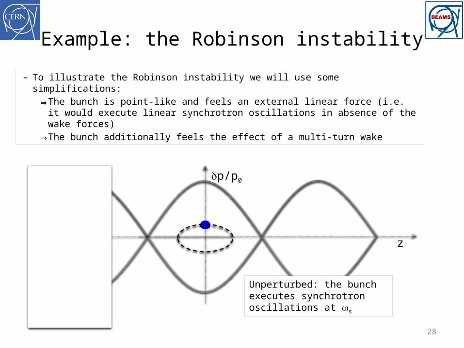
Example: the Robinson instability
– To illustrate the Robinson instability we will use some simplifications:⇒ The bunch is point-like and feels an external linear force (i.e. it would
execute linear synchrotron oscillations in absence of the wake forces)⇒ The bunch additionally feels the effect of a multi-turn wake
z
dp/p0
Unperturbed: the bunch executes synchrotron oscillations at ws

29
The Robinson instability
z
dp/p0
The perturbation changes ws
The perturbation also changes the oscillation amplitudeUnstable motion
– To illustrate the Robinson instability we will use some simplifications:⇒ The bunch is point-like and feels an external linear force (i.e. it would
execute linear synchrotron oscillations in absence of the wake forces)⇒ The bunch additionally feels the effect of a multi-turn wake

30
The Robinson instability
z
dp/p0
The perturbation also changes the oscillation amplitude Damped motion
– To illustrate the Robinson instability we will use some simplifications:⇒ The bunch is point-like and feels an external linear force (i.e. it would
execute linear synchrotron oscillations in absence of the wake forces)⇒ The bunch additionally feels the effect of a multi-turn wake
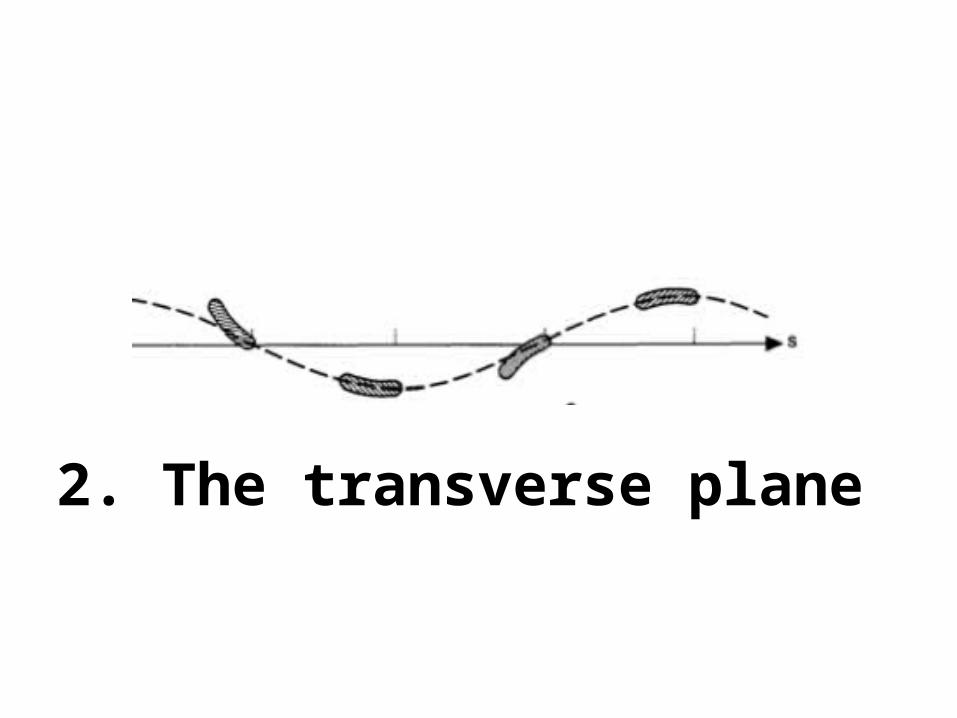
2. The transverse plane

32
Transverse wake function: definition
2b z
Source, q1
Witness, q2
L
– In an axisymmetric structure (or simply with a top-bottom and left-right symmetry) a source particle traveling on axis cannot induce net transverse forces on a witness particle also following on axis
– At the zero-th order, there is no transverse effect– We need to introduce a breaking of the symmetry to drive transverse effect, but at the first
order there are two possibilities, i.e. offset the source or the witness

33
Transverse dipolar wake function: definition
2b z
Source, q1
Witness, q2
L
Dx1 (or Dy1)

34
Transverse dipolar wake function
– The value of the transverse dipolar wake functions in 0, Wx,y(0), vanishes because source and witness particles are traveling parallel and they can only – mutually – interact through space charge, which is not included in this framework
– Wx,y(0--)<0 since trailing particles are deflected toward the source particle (Dx1 and Dx’2 have the same sign)
– Wx,y(z) has a discontinuous derivative in z=0 and it vanishes for all z>0 because of the ultra-relativistic approximation
Wx,y(z)
z
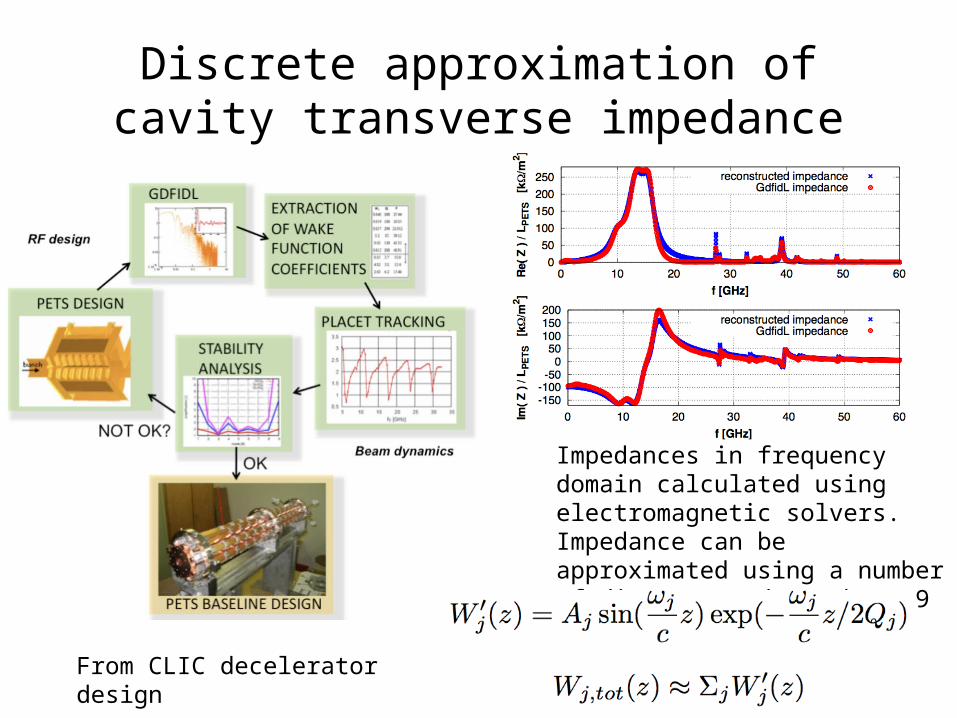
Discrete approximation of cavity transverse impedance
Impedances in frequency domain calculated using electromagnetic solvers. Impedance can be approximated using a number of discrete modes (above 9 modes used).
From CLIC decelerator design
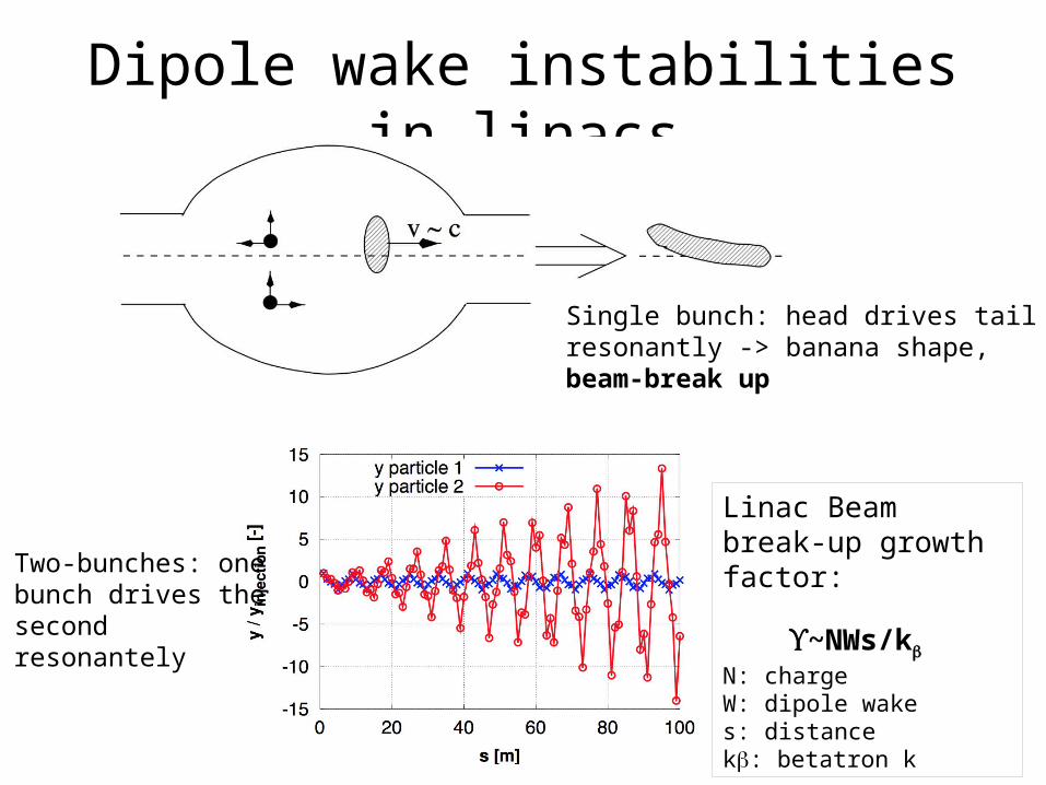
Dipole wake instabilities in linacs
Linac Beam break-up growth factor:
ϒ~NWs/kb
N: chargeW: dipole wakes: distancekb: betatron k
Single bunch: head drives tail resonantly -> banana shape, beam-break up
Two-bunches: one bunch drives the second resonantely

37
Rings: A glance into the head-tail modes
• Different transverse head-tail modes correspond to different parts of the bunch oscillating with relative phase differences. E.g.– Mode 0 is a rigid bunch mode– Mode 1 has head and tail oscillating in counter-phase– Mode 2 has head and tail oscillating in phase and the bunch center in opposition

38
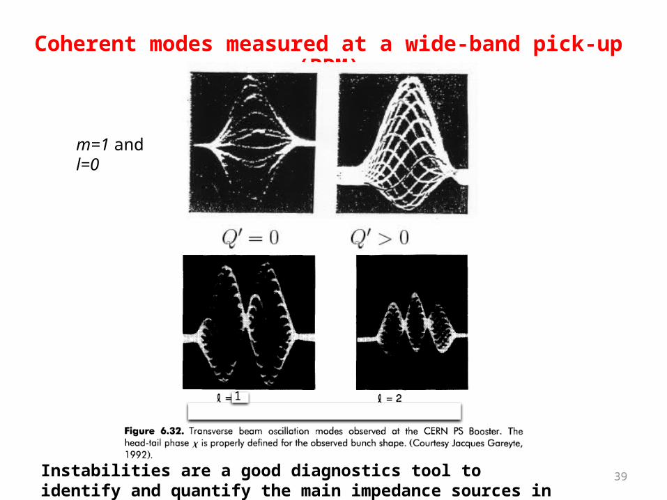
m=1 and l=0
m=1 and l=1
m=1 and l=2
Calculation of coherent modes seen at a wide-band pick-up (BPM) h
• The patterns of the head-tail modes (m,l) depend on chromaticity
Q’=0 Q’≠0
39
Coherent modes measured at a wide-band pick-up (BPM)
m=1 and l=0
1
Instabilities are a good diagnostics tool to identify and quantify the main impedance sources in a machine.
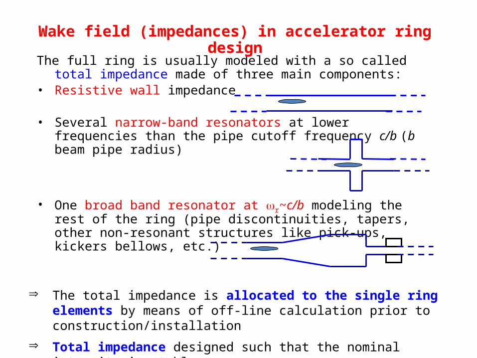
The full ring is usually modeled with a so called total impedance made of three main components:
• Resistive wall impedance
• Several narrow-band resonators at lower frequencies than the pipe cutoff frequency c/b (b beam pipe radius)
• One broad band resonator at wr~c/b modeling the rest of the ring (pipe discontinuities, tapers, other non-resonant structures like pick-ups, kickers bellows, etc.)
Þ The total impedance is allocated to the single ring elements by means of off-line calculation prior to construction/installation
Þ Total impedance designed such that the nominal intensity is stable
Wake field (impedances) in accelerator ring design

We will talk more about wake fields in the lecture about linear colliders (tomorrow).
For more details on wake fields, derived from first physical principles see the excellent book “Physics of Collective Beam Instabilities in High Energy Accelerators”, A. W. Chao (freely available; see course web pages).

Part II

Overview of multi-particle effects
Adapted from G. Rumolo’s slides fromUSPAS Course on collective effects
General definition of multi-particle processes in an accelerator or storage ring
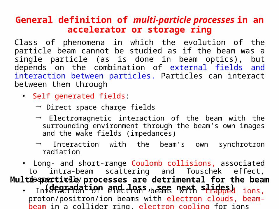
Class of phenomena in which the evolution of the particle beam cannot be studied as if the beam was a single particle (as is done in beam optics), but depends on the combination of external fields and interaction between particles. Particles can interact between them through• Self generated fields:
® Direct space charge fields® Electromagnetic interaction of the beam with the surrounding environment
through the beam‘s own images and the wake fields (impedances)® Interaction with the beam‘s own synchrotron radiation
• Long- and short-range Coulomb collisions, associated to intra-beam scattering and Touschek effect, respectively
• Interaction of electron beams with trapped ions, proton/positron/ion beams with electron clouds, beam-beam in a collider ring, electron cooling for ions
Multi-particle processes are detrimental for the beam (degradation and loss, see next slides)

z
dp/p0
Longitudinal space charge
• Force decays like 1/g2
• it can be attractive above transition
x
y
Transverse space charge
• Force decays like 1/g2
• It is always repulsive
Direct space charge forces (more details later in this lecture)

W0(z)
Model:
A rigid beam with charge q going through a device of length L leaves behind an oscillating field and a probe charge e at distance z feels a force as a result. The integral of this force over the device defines the wake field and its Fourier transform is called the impedance of the device of length L.
q
z
e s
Wake fields, impedances (more details later in this lecture)
L
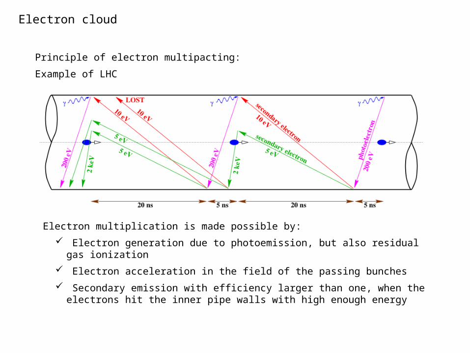
Principle of electron multipacting:
Example of LHC
Electron cloud
Electron multiplication is made possible by:
Electron generation due to photoemission, but also residual gas ionization
Electron acceleration in the field of the passing bunches
Secondary emission with efficiency larger than one, when the electrons hit the inner pipe walls with high enough energy
Several names to describe these effects...‚Multi-particle‘ is the most generic attribute. ‚High-current‘, ‚high-intensity‘, ‚high brightness‘ are also used because these effects are important when the beam has a high density in phase space (many particles in little volume) Other labels are also used to refer to different subclasses
• Collective effects (coherent):® The beam resonantly responds to a self-induced electromagnetic excitation® Are fast and visible in the beam centroid motion (tune shift, instability)
• Collective effects (incoherent):® Excitation moves with the beam, spreads the frequencies of particle motion.® Lead to particle diffusion in phase space and slow emittance growth
• Collisional effects (incoherent):® Isolated two-particle encounters have a global effect on the beam dynamics (diffusion
and emittance growth, lifetime)
• Two-stream phenomena (coherent or incoherent):® Two component plasmas needed (beam-beam, pbeam-ecloud, ebeam-ions) and the
beam reacts to an excitation caused by another „beam“
The performance of an accelerator is usually limited by a multi-particle effect. When the beam current in a machine is pushed above a certain limit (intensity threshold), intolerable losses or beam
quality degradation appear due to these phenomena
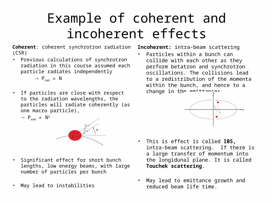
Example of coherent and incoherent effects
Coherent: coherent synchrotron radiation (CSR)• Previous calculations of synchrotron
radiation in this course assumed each particle radiates independently
Prad N
• If particles are close with respect to the radiation wavelengths, the particles will radiate coherently (as one macro particle),
Prad N2
• Significant effect for short bunch lengths, low energy beams, with large number of particles per bunch
• May lead to instabilities
Incoherent: intra-beam scattering• Particles within a bunch can collide with each
other as they perform betatron and synchrotron oscillations. The collisions lead to a redistribution of the momenta within the bunch, and hence to a change in the emittances.
• This is effect is called IBS, intra-beam scattering. If there is a large transfer of momentum into the longidunal plane. It is called Touchek scattering.
• May lead to emittance growth and reduced beam life time.
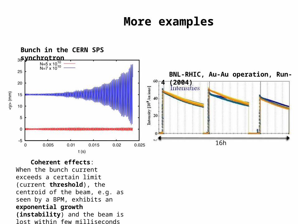
More examples
Coherent effects:When the bunch current exceeds a certain limit (current threshold), the centroid of the beam, e.g. as seen by a BPM, exhibits an exponential growth (instability) and the beam is lost within few milliseconds
BNL-RHIC, Au-Au operation, Run-4 (2004)
16h
Bunch in the CERN SPS synchrotron
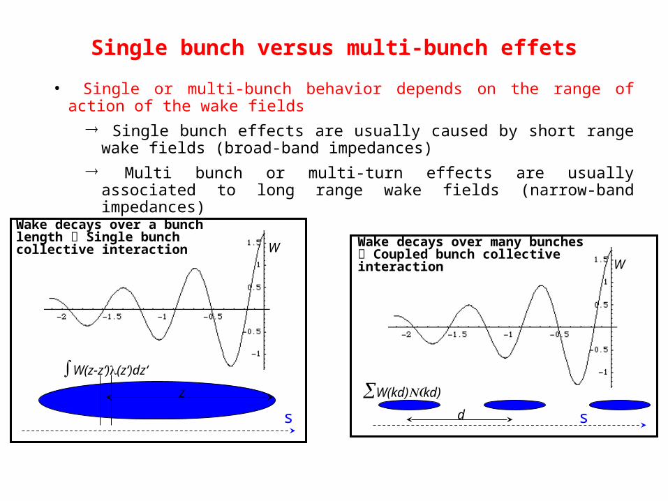
Single bunch versus multi-bunch effets
• Single or multi-bunch behavior depends on the range of action of the wake fields® Single bunch effects are usually caused by short range wake fields (broad-band
impedances)® Multi bunch or multi-turn effects are usually associated to long range wake fields
(narrow-band impedances)
Wake decays over a bunch length Single bunch collective interaction
s
W(z-z‘)l(z‘)dz‘
z
W
s
W(kd) (N kd)
W
d
Wake decays over many bunches Coupled bunch collective interaction
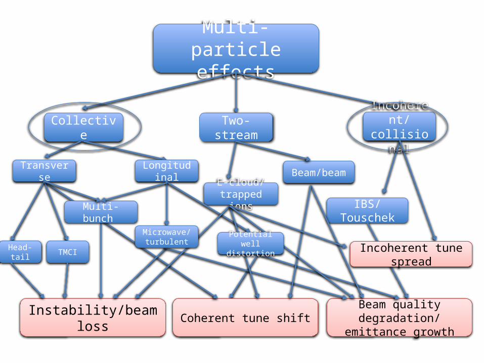
Multi-particle effects
CollectiveIncoherent/collisionalTwo-stream
Transverse Longitudinal
Instability/beam loss Beam quality degradation/ emittance growthCoherent tune shift
Head-tail TMCI
E-cloud/trapped ions
Beam/beam
IBS/Touschek
Incoherent tune spreadPotential well
distortion
Microwave/turbulent
Multi- bunch
Related Documents